WO2021130802A1 - 吸収体及び吸収性物品 - Google Patents
吸収体及び吸収性物品 Download PDFInfo
- Publication number
- WO2021130802A1 WO2021130802A1 PCT/JP2019/050270 JP2019050270W WO2021130802A1 WO 2021130802 A1 WO2021130802 A1 WO 2021130802A1 JP 2019050270 W JP2019050270 W JP 2019050270W WO 2021130802 A1 WO2021130802 A1 WO 2021130802A1
- Authority
- WO
- WIPO (PCT)
- Prior art keywords
- core
- water
- sheet
- absorber
- longitudinal direction
- Prior art date
- Legal status (The legal status is an assumption and is not a legal conclusion. Google has not performed a legal analysis and makes no representation as to the accuracy of the status listed.)
- Ceased
Links
Images




Classifications
-
- A—HUMAN NECESSITIES
- A61—MEDICAL OR VETERINARY SCIENCE; HYGIENE
- A61F—FILTERS IMPLANTABLE INTO BLOOD VESSELS; PROSTHESES; DEVICES PROVIDING PATENCY TO, OR PREVENTING COLLAPSING OF, TUBULAR STRUCTURES OF THE BODY, e.g. STENTS; ORTHOPAEDIC, NURSING OR CONTRACEPTIVE DEVICES; FOMENTATION; TREATMENT OR PROTECTION OF EYES OR EARS; BANDAGES, DRESSINGS OR ABSORBENT PADS; FIRST-AID KITS
- A61F13/00—Bandages or dressings; Absorbent pads
- A61F13/15—Absorbent pads, e.g. sanitary towels, swabs or tampons for external or internal application to the body; Supporting or fastening means therefor; Tampon applicators
- A61F13/53—Absorbent pads, e.g. sanitary towels, swabs or tampons for external or internal application to the body; Supporting or fastening means therefor; Tampon applicators characterised by the absorbing medium
- A61F13/534—Absorbent pads, e.g. sanitary towels, swabs or tampons for external or internal application to the body; Supporting or fastening means therefor; Tampon applicators characterised by the absorbing medium having an inhomogeneous composition through the thickness of the pad
-
- A—HUMAN NECESSITIES
- A61—MEDICAL OR VETERINARY SCIENCE; HYGIENE
- A61F—FILTERS IMPLANTABLE INTO BLOOD VESSELS; PROSTHESES; DEVICES PROVIDING PATENCY TO, OR PREVENTING COLLAPSING OF, TUBULAR STRUCTURES OF THE BODY, e.g. STENTS; ORTHOPAEDIC, NURSING OR CONTRACEPTIVE DEVICES; FOMENTATION; TREATMENT OR PROTECTION OF EYES OR EARS; BANDAGES, DRESSINGS OR ABSORBENT PADS; FIRST-AID KITS
- A61F13/00—Bandages or dressings; Absorbent pads
- A61F13/15—Absorbent pads, e.g. sanitary towels, swabs or tampons for external or internal application to the body; Supporting or fastening means therefor; Tampon applicators
- A61F13/53—Absorbent pads, e.g. sanitary towels, swabs or tampons for external or internal application to the body; Supporting or fastening means therefor; Tampon applicators characterised by the absorbing medium
- A61F13/534—Absorbent pads, e.g. sanitary towels, swabs or tampons for external or internal application to the body; Supporting or fastening means therefor; Tampon applicators characterised by the absorbing medium having an inhomogeneous composition through the thickness of the pad
- A61F2013/53445—Absorbent pads, e.g. sanitary towels, swabs or tampons for external or internal application to the body; Supporting or fastening means therefor; Tampon applicators characterised by the absorbing medium having an inhomogeneous composition through the thickness of the pad from several sheets
Definitions
- the present invention relates to an absorber capable of absorbing body fluids such as urine.
- Absorbent articles such as disposable diapers and sanitary napkins generally include a front sheet that is placed relatively close to the wearer's skin and a back sheet that is placed relatively far from the wearer's skin. , Consists of an absorber interposed between the two sheets.
- This absorber is typically made of a fiber material of a fiber material such as wood pulp, and in many cases, water-absorbent polymer particles are further supported on the fiber material. Since the absorber made of a laminated fiber material of such a fiber material is relatively bulky and thick, it is excellent in cushioning property, etc., but because it is bulky, the appearance of the absorbent article is not refreshed and the appearance is deteriorated.
- an upper layer absorber made of pulp and a water-absorbent polymer and a two-layer sheet arranged adjacent to the non-skin facing surface side of the upper layer absorber As a conventional technique for reducing the thickness of an absorber, for example, in Patent Document 1, an upper layer absorber made of pulp and a water-absorbent polymer and a two-layer sheet arranged adjacent to the non-skin facing surface side of the upper layer absorber. An absorber composed of a lower layer absorber having a water-absorbent polymer arranged between them is described. The lower layer absorber is partitioned into a plurality of water-absorbent polymer placement regions in which particulate water-absorbent polymers are sealed between the two layers of sheets bonded to each other, and between adjacent water-absorbent polymer placement regions. However, the flow path portion is recessed from the water-absorbent polymer arrangement region.
- the water-absorbent polymer is not present in the flow path portion, or is present at a basis weight lower than the water-absorbent polymer arrangement region. Therefore, the water-absorbent polymer is not uniformly distributed in the lower layer absorber.
- the absorber described in Patent Document 1 by adopting the sheet-shaped lower layer absorber mainly composed of a water-absorbent polymer, a sufficient amount of absorption can be secured while being thin, and the above-mentioned Since the upper layer absorber also contains a water-absorbent polymer, it is said that the problem of difficulty in holding the liquid and causing reversion when the pulp is used alone can be solved.
- Patent Document 2 also describes an absorber having a two-layer structure similar to Patent Document 1.
- the lower layer relatively far from the wearer's skin in the two-layer structure is composed mainly of a water-absorbent polymer without substantially containing cellulose.
- Patent Document 3 in a water-absorbent sheet composition having a structure in which an absorbent layer containing a water-absorbent resin and an adhesive is sandwiched between two or more hydrophilic non-woven fabrics, the absorbent layer is thickened by a water-permeable substrate. The ones divided in the direction are described.
- the present invention includes a first sheet and a second sheet that face each other, and an intermediate sheet that is interposed between the two sheets, and absorbs at least water as a water-absorbing material between the first sheet and the intermediate sheet.
- Absorption in which a first core containing a sex polymer is interposed, and a second core containing at least a water-absorbent fiber and a water-absorbent polymer as a water-absorbent material is interposed between the intermediate sheet and the second sheet.
- the body In one embodiment of the absorber of the present invention, 80% by mass or more of the material for forming the first core is a water-absorbent polymer.
- the first core has a larger ratio of the content mass of the water-absorbing polymer to the total mass of the forming material than the second core. In one embodiment of the absorber of the present invention, the first core has a smaller basis weight of the water-absorbing polymer than the second core. In one embodiment of the absorber of the present invention, the flexural rigidity of the laminated structure including the first sheet, the first core, and the intermediate sheet per amount of change in thickness before and after liquid absorption calculated by the following formula (1). When the rate of change is BR, the BR in two directions arbitrarily selected from the two directions orthogonal to each other and the other three directions intersecting the two directions without being orthogonal to each other is 5.0 or less. ..
- the present invention is an absorbent article including the above-mentioned absorber of the present invention.
- Other features, effects and embodiments of the invention are described below.
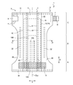
- FIG. 1 is a developed plan view schematically showing a skin-facing surface side (surface sheet side) in an unfolded and stretched state of a deployable disposable diaper according to an embodiment of the absorbent article of the present invention.
- the "expanded and stretched state” here means that the diaper is in the unfolded state as shown in FIG. 1, and the elastic member of each part is stretched to extend the diaper in the unfolded state to eliminate the influence of the elastic member at all. It refers to the state in which it is expanded to the same size as when it is expanded in a flat state.
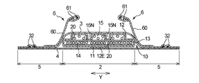
- FIG. 2 is a cross-sectional view schematically showing a cross section taken along line II of FIG.
- FIG. 3 is a plan view schematically showing the skin-facing surface side of the absorber in the disposable diaper of FIG. FIG.
- FIG. 4 is a cross-sectional view schematically showing a cross section along the thickness direction at the position of the absorber shown in FIG. 3 at the center in the longitudinal direction (vertical center line indicated by reference numeral CLx).
- 5 (a) and 5 (b) are cross-sectional views schematically showing a cross section along a thickness direction of a part of an embodiment of the absorber of the present invention, respectively.
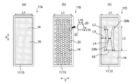
- 6 (a) to 6 (c) are schematic plan views of the first core side laminated structure in Examples or Comparative Examples, respectively.
- FIG. 7 is for measuring the flexural rigidity change rate BR in the vertical and horizontal directions per amount of change in thickness before and after liquid absorption of the laminated structure (first core side laminated structure) composed of the first sheet, the first core and the intermediate sheet.
- FIG. 8 shows the preparation of a sample for measuring the flexural rigidity change rate BR in the diagonal direction per the amount of change in thickness before and after the liquid absorption of the laminated structure (first core side laminated structure) composed of the first sheet, the first core and the intermediate sheet. It is explanatory drawing of the method.
- an object of the present invention is to provide an absorber which is excellent in liquid absorption performance, suppresses an increase in rigidity due to liquid absorption, and is excellent in flexibility even after liquid absorption.
- the absorbent article of the present invention is orthogonal to the longitudinal direction (indicated by reference numeral "X" in the figure) corresponding to the anteroposterior direction of the wearer, that is, the direction extending from the ventral side to the dorsal side via the crotch portion. It has a horizontal direction (indicated by the symbol "Y" in the figure).
- the vertical direction is the vertical direction of the absorbent article or the direction along the vertical direction of its constituent members (for example, an absorber)
- the horizontal direction is the lateral direction of the absorbent article or its constituent members (for example, an absorber). This is the direction along the lateral direction of the constituent members.
- the absorbent article of the present invention includes an absorber (indicated by reference numeral "10" in the figure) that absorbs and retains body fluid.
- 1 and 2 show a disposable diaper 1 which is an embodiment of the absorbent article of the present invention, and the diaper 1 has the above-described configuration.
- the diaper 1 is arranged in the crotch part of the wearer in the vertical direction X, and includes the inseam B including the excretion part facing part (not shown) facing the excretion part such as the penis, and the wearer rather than the crotch part B. It is divided into three parts: a ventral portion A arranged on the ventral side (anterior side) of the inseam and a dorsal portion C arranged on the dorsal side (rear side) of the wearer from the inseam B.
- the ventral portion A and the dorsal portion C each typically include a torso circumference arranged around the wearer's torso when the diaper 1 is worn.
- the ventral part A is a part of the front body of the diaper 1
- the dorsal part C is a part of the back body of the diaper 1.
- the inseam B exists from the front body to the back body of the diaper 1.
- the ventral portion A, the inseam B, and the dorsal portion C can be each region when the unfolded and extended diaper 1 is divided into three equal parts in the vertical direction X1.
- the diaper 1 is a so-called deployable disposable diaper, and as shown in FIG. 1, the diaper 1 is provided with a fastening member 8 having a fastening portion 7 on both side edges of the back side portion C of the diaper 1 along the vertical direction X. A fastening region 9 to which the fastening portion 7 can be fastened is provided on the non-skin facing surface of the ventral side portion A. Further, the diaper 1 includes an absorbent main body 2 having an absorbent body 10 that absorbs and holds body fluid such as urine excreted by the wearer, and a flap portion 5 extending outward from the peripheral edge of the absorbent main body 2. ..
- the absorbent body 2 includes a liquid-permeable front surface sheet 3 that forms a skin-facing surface, a liquid-impermeable or liquid-impermeable or water-repellent back surface sheet 4 that forms a non-skin-facing surface, and both sheets 3 and 4. It is provided with a liquid-retaining absorber 10 interposed between them, and these are integrated by a known joining means such as an adhesive.
- the absorbent body 2 extends in the longitudinal direction X from the ventral side A to the dorsal side C.
- the front surface sheet 3 and the back surface sheet 4 those conventionally used for this kind of absorbent article can be used without particular limitation.
- the surface sheet 3 for example, various non-woven fabrics and perforated films can be used.
- the back sheet 4 for example, a resin film or a laminate of a resin film and a non-woven fabric can be used.
- the "skin facing surface” is a surface of the absorbent article or a component thereof (for example, an absorber) that is directed toward the wearer's skin when the absorbent article is worn, that is, the wearer's skin relatively.
- the “non-skin facing surface” is the surface of the absorbent article or its constituents that faces the opposite side of the skin when the absorbent article is worn, that is, relatively far from the wearer's skin. On the side.
- the term "when worn” as used herein means a state in which the normal proper wearing position, that is, the correct wearing position of the absorbent article is maintained. In FIGS.
- the upper surface (relatively upper surface) of each component is the skin-facing surface and the lower surface (relative).
- the surface located below the surface) is the non-skin facing surface.
- the flap portion 5 is composed of a member extending outward from the peripheral edge of the absorbent main body 2, and is a non-arranged portion of the absorber.
- the front surface sheet 3 covers the entire surface of the absorber 10 facing the skin
- the back surface sheet 4 covers the entire area of the non-skin facing surface of the absorber 10.
- the sheets 3 and 4 further extend outward in the horizontal direction Y from both side edges along the vertical direction X of the absorbent main body 2, and together with the leakage-proof cuff forming sheet 60 described later, a part of the flap portion 5 (absorbent main body).
- Both side edges along the vertical direction X of 2 and side flap portions extending outward in the horizontal direction Y from the virtual extension lines of the both side edges) are formed.
- the plurality of members constituting the flap portion 5 are joined to each other by known joining means such as an adhesive, a heat seal, and an ultrasonic seal.
- leak-proof cuffs 6 that stand up toward the wearer's skin side when worn are arranged along both side portions of the absorbent body 2 along the vertical direction X. More specifically, a pair of sheets 60 for forming a leak-proof cuff that is liquid-resistant, water-repellent, and breathable are included on both sides of the absorbent body 2 on the skin-facing surface along the vertical direction X. Leakage-proof cuffs 6 and 6 are arranged. In each of the pair of leakage-proof cuff forming sheets 60, 60, one end side in the lateral direction Y is fixed to another member (front sheet 3 and back surface sheet 4 in the illustrated embodiment), and the fixed end portion and the lateral direction Y are respectively.
- the other end is a free end that is not fixed to other members.
- An elastic member 61 for forming a leak-proof cuff is fixed at a free end of each leak-proof cuff forming sheet 60 in an extended state in the vertical direction X so as to be expandable and contractible in the same direction.
- the free end side of the sheet 60 for forming a leak-proof cuff raises the fixing portion 62 with other members.
- the standing of the leak-proof cuff 6 prevents the outflow of excrement such as urine to the outside in the lateral direction Y.
- a plurality of elastic members 31 for forming gathers around the waist are arranged so as to be stretchable in the lateral direction Y at the flap portion 5 at the end portion of each of the ventral side portion A and the dorsal side portion C in the vertical direction X, that is, the waist end portion.
- the plurality of elastic members 31 are intermittently arranged at predetermined intervals in the vertical direction X.
- the waist end portions of the ventral side portion A and the dorsal side portion C, which are the arrangement portions are substantially covered over the entire circumference thereof. Circular waist gathers (gathers around the waist) are formed.
- the leg portion arranged around the wearer's leg when the diaper 1 is worn has an elastic member 32 for forming leg gathers that can extend in the vertical direction X at least in the vertical direction X of the inseam B. It extends in the vertical direction X over the entire length of the diaper, so that when the diaper 1 is worn, leg gathers are formed on the leg portion due to the contraction of the elastic member 32.
- These gather-forming elastic members 31 and 32 are all of a plurality of sheets constituting the flap portion 5 (in this embodiment, two of the front surface sheet 3, the back surface sheet 4 and the leakage-proof cuff forming sheet 60). It is sandwiched and fixed in an extended state by a joining means such as an adhesive.
- each of the elastic members 61, 31 and 32 described above is not particularly limited, and for example, a thread-like or string-like (flat rubber or the like) having a rectangular, square, circular or polygonal cross section, or a multifilament type thread-like Etc. can be used.
- the absorber 10 included in the diaper 1 is an embodiment of the absorber of the present invention.
- FIG. 3 shows a cross section of the absorber 10 facing the skin (the side facing the surface sheet 3)
- FIG. 4 shows a cross section of the absorber 10 along the thickness direction at the center position in the vertical direction X.
- FIG. 4 shows the members that are actually in close contact with each other apart from each other, and FIG. 4 does not necessarily represent the actual situation.
- the absorber 10 includes a first sheet 11 and a second sheet 12 facing each other, and an intermediate sheet 13 interposed between the sheets 11 and 12, and the first sheet is the first.
- a water-absorbent first core 14 is interposed between the sheet 11 and the intermediate sheet 13, and a water-absorbent second core 15 is interposed between the intermediate sheet 13 and the second sheet 12.
- the second sheet 12 side is used as the liquid receiving surface side that first comes into contact with the liquid to be absorbed. That is, the absorber 10 is arranged so that the second sheet 12 of the diaper 1 is located closer to the skin of the wearer of the diaper 1 than the first sheet 11.
- the first sheet 11 side can be used as the liquid receiving surface side, but the difference in composition between the first core 14 and the second core 15, in particular, water absorption described later. Considering the difference in the occupancy rate of the sex polymer, it is more preferable to use the second sheet 12 side as the liquid receiving surface side in this way from the viewpoint of improving the liquid drawability and the liquid absorption performance.
- a sheet having liquid permeability or liquid absorption can be used, and typically, a sheet having liquid permeability or liquid absorption can be used. It is a fiber sheet mainly composed of fibers, that is, a fiber sheet having a fiber content of more than 50% by mass.
- Examples of the constituent fibers of the three types of sheets include wood pulp such as coniferous pulp and broadleaf pulp, natural fibers such as non-wood pulp such as cotton pulp and hemp pulp; and modified pulp such as cationized pulp and marcelled pulp ( As mentioned above, cellulosic fibers); synthetic fibers composed of resins such as polyethylene and polypropylene can be mentioned, and one of these can be used alone or in combination of two or more.
- Examples of the three types of sheets include paper, woven fabric, and non-woven fabric.
- Examples of the non-woven fabric include air-through non-woven fabric, heat roll non-woven fabric, spunlace non-woven fabric, spunbond non-woven fabric, melt-blown non-woven fabric, and spunbond-melt-blown.
- the three types of sheets typically have a single-layer structure composed of one of these types, but may also have a laminated structure in which two or more types are laminated and integrated.
- the three types of sheets may have the same composition and form, or may differ from each other.
- the length (width) of the second sheet 12 in the lateral direction Y is the other constituent members of the absorber 10 (first sheet 11, intermediate sheet 13, first core 14 and second core 15). ), which consists of one wide sheet, which is longer than the width (maximum width) of the part having the maximum width.
- the second sheet 12 of the present embodiment has a width of 2 times or more and 3 times or less of the maximum width, and as shown in FIG. 4, covers the entire area of the skin facing surface of the second core 15. It is covered and extends outward in the horizontal direction Y from each of both side edges along the vertical direction X of the second core 15, and the extending portion 12E is wound around the non-skin facing surface side of the first sheet 11.
- the second sheet 12 covers the entire skin-facing surface and non-skin-facing surface of the laminated structure including the first sheet 11, the intermediate sheet 13, the first core 14, and the second core 15.
- the second sheet 12 does not have to include the extending portion 12E, and the second sheet 12 has a width similar to the maximum width of the second core 15 in contact with the second sheet 12. It suffices to have.
- the other components of the absorber 10 first sheet 11, intermediate sheet 13, first core 14 and second core 15
- the second sheet 12 have a maximum width, i.e. a maximum in the lateral direction Y.
- the lengths are about the same as each other.
- the first core 14 is characterized in that more than 80% by mass of the forming material is a water-absorbent polymer. That is, the "water-absorbent polymer occupancy" of the first core 14 (ratio of the content mass of the water-absorbent polymer to the total mass of the material for forming the core) is 80% by mass or more, and the first core 14 is the water-absorbent polymer 20. It is mainly composed of.
- the "material for forming the first core 14" (core forming material) referred to here is between two sheets (specifically, the first sheet 11 and the intermediate sheet 13) located on both sides of the first core 14. Means the substance that exists in. However, the core forming material does not include the adhesive applied to the facing surfaces (inner surfaces) of the two sheets. Therefore, the adhesives shown by reference numerals 22 and 23 in FIG. 4 are not the core forming materials of the first core 14.
- the first core 14 typically contains only the water-absorbent polymer 20 as the water-absorbent material and does not contain water-absorbent fibers such as wood pulp, or even if it contains water-absorbent fibers, the second core 15
- the amount is much smaller than the content of the water-absorbent fiber in (for example, 20% by mass or less).
- a hydrogel material capable of absorbing and retaining water can be generally used, and for example, a polymer or copolymer of acrylic acid or an alkali metal acrylate metal salt can be used. Examples thereof include polyacrylic acid and salts thereof, and polymethacrylic acid and salts thereof, and specific examples thereof include partial sodium salts of acrylic acid polymers.
- the shape of the water-absorbent polymer 20 is not particularly limited, and may be, for example, spherical, tufted, lumpy, bale-shaped, fibrous, amorphous, or a combination of these particles.
- the water-absorbent polymer 20 uses particles having the same shape. It is preferable, and it is also preferable that the particles are spherical.
- the adhesives 22 and 23 have a role of fixing the water-absorbent polymer 20 contained in the first core 14 to the first sheet 11 and / or the intermediate sheet 13 and joining the two sheets 11 and 13 to each other.
- the adhesive 22 is applied to the surface (inner surface) of the first sheet 11 facing the intermediate sheet 13, and the adhesive 23 is applied to the surface (inner surface) of the intermediate sheet 13 facing the first sheet 11. It was done.
- an adhesive that can be used for joining members in this type of absorbent article can be used without particular limitation, and examples thereof include a hot melt adhesive.
- the adhesive 22 and the adhesive 23 may be the same type of adhesive or different types of adhesive, and are typically the former. The adhesives 22 and 23 will be described later.
- the adhesive application pattern of the adhesive 22 on the first sheet 11 side and the adhesive 23 on the intermediate sheet 13 side may be the same or different.
- the adhesive on the liquid receiving surface side that first comes into contact with the liquid to be absorbed in the first core 14 is applied to a predetermined coating region (for example, the region where the water absorbing polymer 20 is present) on the surface to be coated.
- the adhesive is applied so that there is a non-applied portion of the adhesive, and the adhesive on the side opposite to the liquid receiving surface side has substantially no non-applied portion of the adhesive in a predetermined coating area on the surface to be coated.
- the form of coating (so-called solid coating) can be exemplified.
- the liquid receiving surface side is the non-coated portion of the adhesive.
- the intermediate sheet 13 side is the liquid receiving surface side (diaper 1).
- the coating pattern of the adhesive 23 on the intermediate sheet 13 side is a pattern in which the coated portion and the non-coated portion of the adhesive 23 coexist, and the coating pattern of the adhesive 22 on the first sheet 11 side is a so-called solid coating. Just do it.
- the pattern in which the adhesive coated portion and the non-coated portion coexist include a form in which the adhesive coated portion has a spiral shape, a summit shape, an omega shape, a curtain shape, and a stripe shape in a plan view. Be done.
- the adhesive is applied to both sides of the first core 14 in the thickness direction, that is, both the first sheet 11 side and the intermediate sheet 13 side, but in the present invention, either one side is applied.
- Adhesive may be applied only to.
- the basis weight of the adhesive arranged on both sides of the first core 14 (when the adhesive is applied to both the first sheet 11 side and the intermediate sheet 13 side, their total basis weight) is water absorption. From the viewpoint of the balance between the fixation of the sex polymer 20 and the liquid permeability or liquid absorption performance, it is preferably 3 g / m 2 or more, more preferably 5 g / m 2 or more, and preferably 50 g / m 2 or less, more preferably.
- the basis weight of the adhesive referred to here is the adhesion per unit area of the adhesive application target area (specifically, for example, the skin-facing surface of the first sheet 11 or the non-skin-facing surface of the intermediate sheet 13).
- the amount of the agent applied is the amount of the agent applied. Therefore, for example, when the coated portion and the non-coated portion of the adhesive are mixed in the coated region due to the intermittent coating of the adhesive, the basis weight of the adhesive in the coated region is the one in which the non-coated portion is added. is there.
- the second core 15, that is, the layer sandwiched between the intermediate sheet 13 and the second sheet 12, contains at least a water-absorbent fiber (not shown) and a water-absorbent polymer 20 as a water-absorbent material.
- the second core 15 is typically composed mainly of a water-absorbent material.
- the content of the water-absorbent material in the second core 15 is at least 50% by mass or more, and 100% by mass, that is, all of the core-forming materials may be water-absorbent materials.
- the water-absorbent polymer 20 in the second core 15 the same polymer as that contained in the first core 14 can be used.
- water-absorbent fiber examples include wood pulp such as coniferous pulp and broadleaf pulp, natural fiber such as non-wood pulp such as cotton pulp and hemp pulp; and modified pulp such as cationized pulp and marcelled pulp (these are cellulosic fibers). ); Hydrophilic synthetic fibers and the like can be mentioned, and one of these can be used alone or in combination of two or more.
- the water-absorbent fiber contained in the second core 15 is typically a cellulosic fiber.
- the content of the water-absorbent fiber in the second core 15 is preferably 20% by mass or more, more preferably 30% by mass or more, and preferably 90% by mass or less, more preferably 80% by mass or less.
- the term "water absorption" with respect to fibers is easily understood by those skilled in the art, for example, pulp is said to be water absorbent. Similarly, it can be easily understood that thermoplastic fibers are non-absorbent.
- the degree of water absorption of the fiber can be compared with the relative difference in water absorption by the value of the water content measured by the following method, and a more preferable range can be defined.
- the water-absorbent fiber such a water content is preferably 6% or more, and more preferably 10% or more.
- the non-water-absorbent fiber preferably has such a water content of less than 6%, more preferably less than 4%.
- the water content was calculated by applying the water content test method of JIS P8203 mutatis mutandis. That is, after the fiber sample was allowed to stand in a test room having a temperature of 40 ° C. and a relative humidity of 80% RH for 24 hours, the weight W (g) of the fiber sample before the absolute drying treatment was measured in the room. Then, it was allowed to stand in an electric dryer having a temperature of 105 ⁇ 2 ° C. (for example, manufactured by Isuzu Seisakusho Co., Ltd.) for 1 hour to perform an absolute drying treatment of the fiber sample.
- Si silica gel for example, Si silica gel (for example,)
- Si silica gel for example, Si silica gel (for example,)
- Saran Wrap registered trademark
- Toyoda Kako Co., Ltd. is placed in a glass desigator (for example, manufactured by Tech Jam Co., Ltd.) and allowed to stand until the temperature of the fiber sample reaches 20 ⁇ 2 ° C.
- the constant weight W'(g) of the fiber sample is weighed, and the water content of the fiber sample is obtained by the following formula.
- Moisture content (%) ⁇ (W-W') / W' ⁇ x 100
- the second core 15 can be manufactured according to a conventional method using a known fiber stacking device equipped with a rotating drum.
- the fiber stacking device typically has a rotating drum having an accumulation recess formed on the outer peripheral surface thereof, and a flow path inside which conveys a core forming material (water-absorbent fiber, water-absorbing polymer) to the accumulation recess.
- the core is provided with a duct, and while rotating the rotating drum around a rotation axis along the circumferential direction of the drum, the core is carried on an air flow generated in the flow path by suction from the inside of the rotating drum.
- the forming material is made to be stacked in the accumulation recess.
- the fiber stack formed in the accumulation recess by the fiber stacking step is the second core 15.
- the second core 15 can be referred to as a “fiber-type absorbent core” from such a typical manufacturing method.
- the second core 15 has a low rigidity portion 15N in which the core forming material (water-absorbent fiber, water-absorbent polymer, etc.) of the second core 15 does not exist or exists in a lower basis weight than the peripheral portion.
- the name "low rigidity portion” is derived from the fact that the non-existing portion or the low basis weight existing portion of the core forming material has lower rigidity than the other portions.
- the low-rigidity portion 15N is a through hole in which the core forming material does not exist, as shown in FIGS. 2 and 4.
- the basis weight of the low-rigidity portion 15N having a lower basis weight is preferably the basis weight of the peripheral portion. It is 50% or less, more preferably 30% or less. Further, it is preferable that the basis weight of the low-rigidity portion 15N, which is not a through hole, is smaller than that of the portion other than the low-rigidity portion 15N in the second core 15, preferably 80 g / m 2. Below, it is more preferably 50 g / m 2 or less.
- the most preferable form of the second core 15 is a through hole having a basis weight of zero as shown in the figure.
- the low-rigidity portion 15N is formed symmetrically with reference to the horizontal center line CLY that bisects the second core 15 in the horizontal direction Y and extends in the vertical direction X. And a pair is formed on both sides of the horizontal center line CLi.
- Each of the pair of low-rigidity portions 15N has a long shape in the vertical direction X (longitudinal direction of the second core 15) in a plan view, specifically, a rectangular shape.
- the low-rigidity portion 15N contributes to the reduction of discomfort when wearing the diaper 1 and the improvement of liquid uptake and diffusivity. That is, the low-rigidity portion 15N acts as a deformation guiding portion (flexible shaft) when the second core 15 provided with the low-rigidity portion 15N is deformed by being bent by receiving an external force such as body pressure, whereby the absorber 10 acts. Deformation along the body shape of the wearer is promoted, and as a result, the discomfort when wearing the diaper 1 can be reduced, and the wearing feeling and the fit can be improved.
- the low-rigidity portion 15N functions as a flow path for excrement such as urine to be absorbed by the absorber 10, promotes diffusion of the excrement in the plane direction, and contributes to effective utilization of the liquid absorption performance of the absorber 10. Can be done. Since the low-rigidity portion 15N plays such a role, it is preferable that the low-rigidity portion 15N is arranged in a portion of the second core 15 that is easily affected by an external force such as body pressure and in which excrement is easily concentrated. From such a viewpoint, it is preferable that the low-rigidity portion 15N is arranged at a portion of the second core 15 located at the lower part of the crotch B. From the same viewpoint, as shown in FIG. 3, the low-rigidity portion 15N preferably extends the vertical center line CLx of the absorber 10 across the vertical direction X.
- the length L (see FIG. 3) of the low-rigidity portion 15N in the vertical direction X (longitudinal direction) is preferably the length L0 (see FIG. 3) of the second core 15 in the vertical direction X (longitudinal direction). It is 20% or more, more preferably 30% or more, and preferably 95% or less, more preferably 85% or less.
- the length or width W (see FIG. 3) of the low-rigidity portion 15N in the lateral direction is preferably 1 mm or more, more preferably 2 mm or more, and preferably 25 mm or less, more preferably 20 mm or less.
- 3) between the two low-rigidity portions 15N and 15N adjacent to each other in the lateral direction Y is preferably 10 mm or more, more preferably 15 mm or more, and preferably 80 mm or less, more preferably 60 mm or less. is there.
- the low-rigidity portion 15N is a portion formed by intentionally inhibiting the stacking of the forming material in the fiber stacking step of the forming material (water-absorbent fiber, water-absorbing polymer, etc.) at the time of manufacturing the second core 15. Is.
- the second core 15 having the low-rigidity portion 15N can be manufactured according to a conventionally known manufacturing method of an absorbent core, and typically, a forming material supplied on an air stream is applied to the outer peripheral surface of the rotating drum.
- the portion corresponding to the low rigidity portion 15N at the bottom of the recess for accumulation is said to be the concave portion for accumulation as compared with the peripheral portion. It can be manufactured by using a rotating drum that protrudes outward in the radial direction.
- the portion where the forming material does not exist or exists at a lower basis weight than the peripheral portion is the low rigidity portion 15N.
- the second sheet 12 and the intermediate sheet 13 are joined and the intermediate sheet 13 is joined in a region where the low-rigidity portion 15N, which is a through hole, overlaps in a plan view. And the first sheet 11 are joined.
- the means for joining the intermediate sheet 13 and the second sheet 12 in the low-rigidity portion 15N is not particularly limited, and fusion may be performed by heat sealing, ultrasonic sealing, or the like, but in the present embodiment, the adhesives 24 and 25 Is.
- the second sheet 12 and the intermediate sheet 13 need to be joined to the low-rigidity portion 15N over the entire area overlapping in a plan view, that is, the entire area needs to be a joint portion of both sheets 12 and 13. It suffices if they are joined in at least a part of the region. That is, in the region where the low-rigidity portion 15N and the low-rigidity portion 15N overlap in a plan view, a portion where the second sheet 12 and the intermediate sheet 13 are in close contact with each other via the adhesives 24 and 25 and a portion where the second sheet 12 and the intermediate sheet 13 are not in close contact with each other but are in close contact with each other Can be mixed.
- the second sheet 12 and the intermediate sheet 13 are at least in a region that overlaps the low-rigidity portion 15N in a plan view, preferably 10% or more, more preferably 30% or more, and preferably 90% or less, more preferably 80% or less. It is preferable that the water-absorbent polymer is supported at an appropriate position and the water-absorbent polymer is supported in close contact with each other from the viewpoint of ensuring a space in which the water-absorbent polymer can swell.
- the above-mentioned description of joining the second sheet 12 and the intermediate sheet 13 in the region where the low-rigidity portion 15N overlaps in a plan view can also be applied to joining the intermediate sheet 13 and the first sheet 11 in the region.
- the absorber 10 has a laminated structure in which two water-absorbent layers (first core 14 and second core 15) are laminated with an intermediate sheet 13 sandwiched between them, and the two layers absorb water.
- first core 14 and second core 15 two water-absorbent layers
- intermediate sheet 13 sandwiched between them
- the two layers absorb water.
- one of the main features of the absorber 10 is that the distribution of the water-absorbent polymer in the laminated structure satisfies the following (i) to (iii).
- the water-absorbent polymer occupancy of the first core 14 (the ratio of the content mass of the water-absorbent polymer to the total mass of the core-forming material) is 80% by mass or more.
- the first core 14 has a larger occupancy rate of the water-absorbing polymer than the second core 15.
- the first core 14 has a smaller basis weight (mass per unit area) of the water-absorbing polymer than the second core 15. That is, regarding the basis weight of the water-absorbent polymer, the magnitude relationship of "first core 14 ⁇ second core 15" is established.
- water-absorbent polymer basis weight refers to the basis weight of the water-absorbent polymer in a portion other than the portion when the core has a portion such as a low-rigidity portion 15N in which a core-forming material does not exist. Means.
- the water-absorbent polymer occupancy of the first core 14 is at least 80% by mass or more, preferably 85% by mass or more, and more preferably 90% by mass or more. Further, the water-absorbent polymer occupancy of the first core 14 may be 100% by mass.
- the ratio of the water-absorbent polymer occupancy of the first core 14 to the water-absorbent polymer occupancy of the second core 15 is preferably 1.1 or more as the former / the latter on the premise that the former> the latter. , More preferably 1.3 or more, and preferably 5.0 or less, more preferably 3.5 or less.
- the water-absorbent polymer occupancy of the second core 15 is preferably 30% by mass or more, more preferably 35% by mass or more, and preferably 90% by mass or less, more preferably 80% by mass or less.
- the ratio of the basis weight of the water-absorbent polymer of the first core 14 to the basis weight of the water-absorbent polymer of the second core 15 is preferably 1. It is 1 or more, more preferably 1.3 or more, and preferably 10.0 or less, more preferably 5.0 or less.
- the basis weight of the water-absorbent polymer of the first core 14 is preferably 60 g / m 2 or more, more preferably 80 g / m 2 or more, and preferably 700 g / m 2 or less, more preferably 500 g / m 2 or less. ..
- the basis weight of the water-absorbent polymer of the second core 15 is preferably 65 g / m 2 or more, more preferably 70 g / m 2 or more, and preferably 800 g / m 2 or less, more preferably 600 g / m 2 or less. ..
- the absorber 10 satisfies the above (i) to (iii) with respect to the distribution of the water-absorbent polymer, and further (iv) "a laminated structure composed of the first sheet 11, the first core 14 and the intermediate sheet 13".
- first core side laminated structure when BR is the rate of change in bending rigidity per amount of change in thickness before and after liquid absorption calculated by the following formula (1), two directions orthogonal to each other. Characterized by the fact that the BR of the two directions arbitrarily selected from the three directions of the other directions that intersect the two directions without being orthogonal to each other is 5.0 or less (BR ⁇ 5.0 holds). Be done.
- the "three directions” are not particularly limited and can be set arbitrarily.
- the vertical direction X (the front-back direction of the wearer of the absorbent article to which the absorber is applied) and the horizontal direction Direction Y (direction orthogonal to the front-back direction of the wearer) and "direction intersecting both directions X and Y and forming an angle between both directions X and Y at 45 degrees" (hereinafter, also referred to as "diagonal direction D"). .)
- the absorber 10 at least two of the BR in the vertical direction X, the BR in the horizontal direction Y, and the BR in the diagonal direction D of the first core side laminated structure are all 5.0 or less.
- BR ⁇ 5.0 is established in two or more directions in the laminated structure on the first core side means that the increase in rigidity of the first core 14, which is the main body thereof, due to liquid absorption is suppressed, that is, (B). It means that the value of w / B d ) is relatively small and has flexibility even after absorbing liquid. Further, BR is obtained by dividing the rate of change in flexural rigidity of the first core-side laminated structure before and after liquid absorption by the amount of change in thickness of the first core-side laminated structure before and after absorbing liquid, as shown in the above formula (1).
- the amount of change in thickness is relatively large, that is, the degree of swelling of the first core 14 after absorbing liquid is relatively large, but the rate of change in flexural rigidity is relatively small, BR ⁇ 5. 0 can hold.
- the first core 14 can be absorbed in the first core 14 regardless of the degree of swelling due to the absorption of the liquid.
- the water-absorbent polymer 20 is hard to be clogged and the first core 14 is relatively soft and swells. Therefore, by satisfying the above (iv), the absorber 10 is suppressed from increasing in rigidity due to liquid absorption and is excellent in flexibility even after absorbing liquid. Therefore, the diaper 1 provided with this is stiff to the wearer. It is hard to give a feeling of discomfort when worn, and it is excellent in wearing feeling not only before absorbing liquid but also after absorbing liquid.
- the absorber 10 satisfies not only the above (iv) but also the above (i) to (iii), and the water-absorbent polymer occupancy and the basis weight of the first core 14 are set in the above-mentioned appropriate ranges. Therefore, not only the change in rigidity due to liquid absorption is suppressed, but also the liquid absorption performance is excellent. Further, the effect of suppressing the change in rigidity due to liquid absorption is not achieved only by satisfying the above (iv), but also satisfies the above (i) to (iii), and the water-absorbing polymer occupancy of the first core 14 and the like. It is also important that the basis weight is set within an appropriate range. In short, it is necessary to satisfy all of the above (i) to (iv) in order to exhibit the predetermined effect of the present invention.
- the BR of the first core side laminated structure in each of the three directions is 5.0 or less.
- all BRs of the first core-side laminated structure in the vertical direction X, the horizontal direction Y, and the diagonal direction D are 5.0 or less.
- the BR of each of the two directions arbitrarily selected from the three directions of the first core side laminated structure is at least 5.0 or less, preferably 4.8 or less, and more preferably 4 as described above. It is less than 5.5. Further, the lower limit of BR in each of the two directions arbitrarily selected from the three directions of the first core side laminated structure is not particularly limited, but is preferably 0.1 from the viewpoint of maintaining the minimum shape as an absorber. Above, more preferably 0.3 or more.
- the physical property values such as B w used for calculating BR are not particularly limited, but are preferably set as follows from the viewpoint of more reliably achieving the predetermined effect of the present invention.
- the flexural rigidity B w of the first core-side laminated structure after absorbing liquid in the vertical direction X, the horizontal direction Y, or the diagonal direction D is preferably as small as possible from the viewpoint of improving the flexibility of the absorber 10, preferably 200 mN ⁇ cm 2. It is / cm or less, more preferably 100 mN ⁇ cm 2 / cm or less.
- the flexural rigidity B d of the first core-side laminated structure before liquid absorption in the vertical direction X, the horizontal direction Y, or the diagonal direction D is preferably as small as possible from the viewpoint of improving the flexibility of the absorber 10, and is preferably 19.6 mN. It is cm 2 / cm or less, more preferably 15 mN ⁇ cm 2 / cm or less.
- the method for measuring the flexural rigidity B w , B d and the thicknesses T0 w , T0 d of the first core side laminated structure will be described later.
- the water-absorbent polymer arrangement region In a plan view (projection view in the thickness direction of the first core 14), there is a state in which the water-absorbent polymer 20 is arranged in such a manner that a gap that can be visually recognized macroscopically is not observed.
- no gap that can be visually recognized macroscopically means that the water-absorbent polymer 20 is one surface of the first sheet 11 or the intermediate sheet 13 when the area where the water-absorbent polymer 20 is arranged is viewed with the naked eye. Although it is arranged so as to evenly cover the (inner surface), it is permissible that a gap between the water-absorbing polymers 20 is unintentionally formed when the arrangement region is viewed microscopically. Is. This void is about 10 to 1000 ⁇ m. Further, the arrangement region of the water-absorbent polymer 20 in the first core 14 is typically substantially the entire area in the plan view (projective view in the thickness direction) of the first core 14.
- the second core 15 has a low-rigidity portion 15N (see FIG. 3 and the like), which reduces discomfort when wearing the diaper 1 and improves liquid uptake and diffusivity. The effect of improvement is achieved.
- the water-absorbent polymer is uniformly distributed in the region where the low-rigidity portion 15N exerts such an action and effect in a plan view, the action and effect of the low-rigidity portion 15N can be more reliably achieved. Therefore, it is preferable that the water-absorbent polymer 20 is uniformly distributed in the region of the first core 14 that overlaps with the low-rigidity portion 15N in a plan view. That is, it is preferable that BR ⁇ 5.0 is established in at least two directions of the region overlapping the low-rigidity portion 15N in the first core side laminated structure in a plan view.
- the absorber 10 of the present embodiment is used as an absorber of the diaper 1 which is an absorbent article arranged in the crotch portion of the wearer. Since the region where various properties such as liquid absorption performance and flexibility after liquid absorption are particularly important is the region arranged in the crotch portion of the wearer of the absorbent article, the water-absorbent polymer is uniform in this region. It is preferable that it is distributed in. From such a viewpoint, it is preferable that the water-absorbent polymer 20 is uniformly distributed in the region arranged in the crotch portion of the wearer when the diaper 1 is worn in the first core 14. That is, it is preferable that BR ⁇ 5.0 is established in at least two directions of the region located in the crotch portion B in the first core side laminated structure.
- the ratio of B w between the two directions arbitrarily selected from the three directions is 0.8 or more and 1.2, respectively.
- the first sheet 11 and the intermediate sheet 13 are joined via the adhesives 22 and 23.
- the joining form of both sheets 11 and 13 as shown in FIG. 5A, via a columnar portion 26 made of an adhesive 22 on the first sheet 11 side and / or an adhesive 23 on the intermediate sheet 13 side.
- a form in which both sheets 11 and 13 are joined can be mentioned. In such a bonded form via the columnar portion 26, the sheets 11 and 13 do not come into close contact with each other and are in a state of being close to each other at a predetermined interval.
- the columnar portion 26 is typically regular or regular in the coating regions of the adhesives 22 and 23 (the region where the water-absorbent polymer 20 exists) in the plan view (projective view in the thickness direction) of the first core side laminated structure. Multiple irregular scattered dots are formed.
- the heights (lengths of the first core 14 in the thickness direction) of the plurality of columnar portions 26 may be the same or different from each other.
- the plurality of columnar portions 26 are bonded to the water-absorbent polymer 20 interposed between the sheets 11 and 13 (the one to be bonded to both the sheets 11 and 13 and the water-absorbent polymer 20) and to the water-absorbent polymer 20. Those that do not (those that join only both sheets 11 and 13) may be mixed.
- the formation of the columnar portion 26 can be controlled by appropriately adjusting the type and coating amount of the adhesive to be used, the basis weight and particle size of the water-absorbent polymer 20 interposed between the sheets 11 and 13.
- the portion where the first sheet 11 and the intermediate sheet 13 are joined via the columnar portion 26 and the both sheets 11 and 13 are connected to each other.
- the portion 16 that is in close contact with the adhesives 22 and 23 is mixed.
- the close contact portion 16 between the two sheets 11 and 13 is formed in a region where the low rigidity portion 15N and the low rigidity portion 15N overlap in a plan view, but the formation portion of the close contact portion 16 is not particularly limited.
- a plurality of regular or irregular scattered spots may be formed in the coating area (the area where the water-absorbent polymer 20 exists) of the adhesives 22 and 23.
- such a close contact portion 16 between the sheets 11 and 13 does not exist or exists. It is preferable that the amount is small.
- an adhesive that facilitates the formation of the columnar portion 26 it is preferable to use an adhesive that has the flexibility to expand following the swelling change accompanying the liquid absorption of the water-absorbent polymer 20.
- raw materials include (co) polymers of vinyl monomers such as 2-ethylhexyl acrylate, butyl acrylate, ethyl acrylate, cyanoacrylate, vinyl acetate, and methyl methacrylate (ethylene vinyl acetate copolymer and the like).
- Etc. acrylic adhesive containing one or more, silicone-based adhesive containing polydimethylsiloxane polymer polymer, etc., and natural rubber-based adhesive containing natural rubber, polyisoprene, chloroprene, etc.
- Isoprene-based adhesive styrene-butadiene copolymer (SBR), styrene-isoprene-styrene block copolymer (SIS), styrene-butadiene-styrene block copolymer (SBS), styrene-ethylene-butadiene-styrene block Examples thereof include rubber-based adhesives such as styrene-based adhesives containing one or more polymers (SEBS) and styrene-ethylene-propylene-styrene block copolymers (SEPS). These may be used individually by 1 type or in combination of 2 or more type.
- SEBS styrene-based adhesives containing one or more polymers
- SEPS styrene-ethylene-propylene-styrene block copolymers
- these adhesives those which are excellent in flexibility and elasticity, maintain the bonded state between the first sheet 11 and the intermediate sheet 13 even after the swelling of the water-absorbent polymer 20, and develop shrinkage force.
- a rubber-based adhesive as the adhesives 22 and 23 used for the first core 14, and the rubber-based adhesive.
- a styrene adhesive it is more preferable to use a styrene adhesive.
- the adhesives 22 and 23 used for the first core 14 are preferably hot melt adhesives.
- the hot melt adhesive include the above-mentioned various adhesives, tackifiers such as petroleum resin and polyterpene resin, plasticizers such as paraffin oil, and, if necessary, phenol-based, amine-based, and phosphorus-based adhesives. It may contain an antioxidant such as a benzimidazole type.
- the adhesives 22 and 23 used for the first core 14 have a relaxation time obtained by viscoelasticity measurement of preferably 1 second or longer, more preferably 2 seconds or longer, still more preferably 3 seconds or longer at 50 ° C.
- a relaxation time obtained by viscoelasticity measurement preferably 1 second or longer, more preferably 2 seconds or longer, still more preferably 3 seconds or longer at 50 ° C.
- the relaxation time of the adhesive obtained by viscoelasticity measurement at 50 ° C. is calculated as the reciprocal of the value of tan ⁇ obtained when the dynamic viscoelasticity of the adhesive is measured under the following conditions. Specifically, a rotary leometer (manufactured by Antoniopas, model "Physica MCR301”) is used, and a plan-viewing circular receiving plate that supports the measurement sample from below and a plane that is arranged facing above the receiving plate. Adhesives (adhesives 22, 23) to be measured are interposed and arranged between the pressure plate and the visual circle-shaped pressing plate. The adhesive in this state has a circular shape in a plan view, and has a thickness of 1.5 mm and a diameter of 12 mm.
- the frequency at the time of measurement is set to 1 Hz
- the strain amplitude is set to 0.05%
- the cooling rate is set to 2 ° C./min
- the measurement is performed in the temperature range from 120 ° C. to ⁇ 10 ° C.
- tan ⁇ is a value obtained by dividing the loss elastic modulus G ”by the storage elastic modulus G ′.
- the first sheet 11 and the extending portion 12E of the second sheet 12 are joined via an adhesive 21, and the intermediate sheet 13 and the second core 15 are bonded to the adhesive 24.
- the second sheet 12 and the intermediate sheet 13 are joined via adhesives 24 and 25.
- an adhesive that can be used for joining members in this type of absorbent article can be used without particular limitation, and examples thereof include a hot melt adhesive.
- the coating amount and coating pattern of the adhesives 21, 24 and 25 are not particularly limited and can be set as appropriate.
- the absorber 10 has a shape that is long in one direction in a plan view.
- the absorber 10 has a long shape in the vertical direction X of the diaper 1, specifically a rectangular shape, and the longitudinal direction of the absorber 10 coincides with the vertical direction X and is orthogonal to the longitudinal direction.
- the width direction coincides with the horizontal direction Y.
- the first core 14 and the second core 15 also have a long shape in the vertical direction X.
- the plan view shape of the second core 15 is substantially the same as that of the intermediate sheet 13.
- the absorber 10 is a virtual center of the absorber 10 in the longitudinal direction, that is, the absorber 10 is bisected in the vertical direction X and extends in the horizontal direction Y.
- One side (left side in FIG. 3) of the absorber 10 in the longitudinal direction (longitudinal direction X) is the other side (FIG. 3) of the absorber 10 in the longitudinal direction (longitudinal direction X) with the vertical center line CLx as a boundary.
- there are more water-absorbent materials water-absorbent polymer, water-absorbent fiber, etc.
- the core-forming material of the absorber 10 typically, for example, 100% by mass of the total mass of the core-forming material is the water-absorbent material, so that the water-absorbent material is the absorber 10 as described above. If it is unevenly distributed in a part of the absorbent body 10, the uneven distribution of the water-absorbent material is reflected in the outer shape of the absorber 10 as shown in FIG. Therefore, when almost all of the core-forming materials are water-absorbent materials, the above-mentioned "more water-absorbent materials are present on one side of the absorber 10 in the longitudinal direction than on the other side in the longitudinal direction of the absorber 10".
- the "water-absorbent material" in the above can be paraphrased as a "core-forming material".
- the water-absorbent material core-forming material in the above-mentioned absorber 10
- the above-mentioned "uniform presence of water-absorbent material (core-forming material)” is defined by a macroscopic observation of the first core 14 or the second core 15 or the absorber 10 (for example, by the naked eye of the first core 14 or the like). In the observation), it means a state in which the water-absorbent material (core forming material) is recognized to be present evenly as a whole, and a part of the first core 14 and the like is microscopically observed (for example, the first core 14 and the like). Uniformity in the strict sense, which can be confirmed for the first time in microscopic observation of the cross section of the above, does not matter.
- the form of 2) above is adopted as the form of uneven distribution of the water-absorbent material (core forming material). That is, the second core 15 extends across the center of the longitudinal direction (longitudinal direction X) (vertical center line CLx of the absorber 10) in the same direction, and extends in the longitudinal direction of the absorber 10 in the second core 15 (longitudinal direction X). The portion located on one side of the vertical direction X (left side in FIG. 3) is located on the other side of the absorber 10 in the second core 15 in the longitudinal direction (longitudinal direction X) (right side in FIG. 3). ), There are more water-absorbent materials (core-forming materials).
- the absorber 10 is defined as the ventral side (the part closer to the ventral side of the wearer of diaper 1) and the dorsal side (the part closer to the dorsal side of the wearer of diaper 1) with the vertical center line CLx as the boundary.
- the portion of the water-absorbent material (core forming material) of the second core 15 located on the ventral side is larger than the portion located on the dorsal side.
- the water-absorbent material (core forming material) is uniformly present.
- the portion (left side in FIG. 3) located on one side of the absorber 10 in the longitudinal direction (longitudinal direction X) of the second core 15 is the second core 15.
- the area of the main surface is larger than that of the portion (right side in FIG. 3) located on the other side of the absorber 10 in the longitudinal direction (longitudinal direction X).
- the "main surface” here means the surface having the maximum area in the second core 15, and is usually the surface that first comes into contact with the liquid to be absorbed or the surface opposite to the liquid receiving surface. Yes, or a skin-facing or non-skin-facing surface. Unless otherwise specified, this definition of the main surface also applies to other members such as the first core 14 and the absorber 10.
- the first core 14 (intermediate sheet 13) has a rectangular shape, the area of the main surface is larger than that of the second core 15, and the second core 15 has a larger main surface area. It is arranged so as to fit in the area surrounded by the peripheral edge of the first core 14 (intermediate sheet 13), and does not extend outward from the peripheral edge of the first core 14.
- the second core 15 has a shorter length in the longitudinal direction (longitudinal direction X) than the first core 14 (intermediate sheet 13), and the length of the second core 15 in the vertical direction X and that of the first core 14
- the ratio is preferably 1.05 or more, more preferably 1.1 or more, and preferably 1.7 or less, more preferably 1.6 or less, as the latter / former, assuming the former ⁇ the latter.
- the length (width) of the second core 15 in the width direction (horizontal direction Y) is not constant over the entire length in the longitudinal direction, and is relatively wide with the wide portion 15A having a relatively wide main surface area.
- the second core 15 is arranged on the peripheral edge of the arrangement surface of the second core 15 on the intermediate sheet 13 (the surface facing the skin of the intermediate sheet 13 in the present embodiment), particularly on the outer side of the narrow portion 15B in the lateral direction Y. There is a portion where the intermediate sheet 13 is exposed, and the intermediate sheet 13 and the second sheet 12 are joined via adhesives 24 and 25 at the exposed portion of the intermediate sheet 13 (FIG. 6). 4).
- the ratio of the maximum length (maximum width) of the wide portion 15A in the lateral direction to the maximum width of the narrow portion 15B is preferably 1.1 or more, more preferably 1.2 or more, and more preferably 1.2 or more as the former / latter. It is preferably 5.5 or less, more preferably 3.0 or less.
- the ratio of the length X in the vertical direction of the wide portion 15A to the length X in the vertical direction of the narrow portion 15B is preferably 1.2 or more, more preferably 1.5 or more, and preferably 7 as the former / latter. It is 0.0 or less, more preferably 5.0 or less.
- the side where the water-absorbent material (core forming material) is unevenly distributed in the longitudinal direction, that is, the wide portion 15A side of the second core 15 is the diaper 1. It is arranged so as to be located closer to the ventral side A.
- the body fluid to be absorbed is usually concentrated in a specific place, specifically, the inseam B or the central portion of the diaper 1 in the vertical direction X, or in addition to these.
- the portion of the absorber 10 in which a relatively large amount of water-absorbing material (core-forming material) is present is located in the region where the liquids are concentrated. , It is preferable to arrange the absorber 10. By doing so, both the liquid absorption performance of the absorber 10 and the thinning can be achieved.
- the magnitude relationship of "first sheet 11 ⁇ second sheet 12 ⁇ intermediate sheet 13" is established, and the Krem water absorption height of the intermediate sheet 13 is 5 minutes. 20 mm or more, preferably 25 mm or more.
- the establishment of the magnitude relationship is mainly effective in increasing the utilization efficiency of the water-absorbent polymer 20 of the first core 14 by quickly absorbing the liquid and diffusing it in the plane direction, and the Krem water absorption of the intermediate sheet 13. Having the height in the above range is mainly effective in increasing the diffusivity of the liquid in the surface direction. Therefore, the absorber 10 satisfying these conditions is particularly excellent in liquid absorption performance.
- the Krem water absorption height is an index of liquid retention, and the higher the Krem water absorption height, the higher the liquid retention of the fiber sheet.
- Crepe paper is particularly preferable as the intermediate sheet 13 from the viewpoint of establishing the magnitude relationship with respect to the Krem water absorption height.
- Crepe paper may be used as the first sheet 11 and the second sheet 12.
- Crepe paper is paper with folds and wrinkles. Since folds and wrinkles make the paper elastic, crepe paper has a larger surface area when stretched than ordinary paper. Due to these characteristics of the crepe paper, the intermediate sheet 13 and the like made of the crepe paper have a relatively high Krem water absorption height, and therefore have excellent liquid drawability, and the rigidity of the liquid absorption state is relatively low. ..
- the degree of crepe on the crepe paper is preferably 5% or more, more preferably 10% or more, still more preferably 15% or more, and 30% or less in terms of the crepe ratio measured by the underwater elongation method. It's realistic.
- the intermediate sheet 13 a crepe paper having a crepe ratio in the above-mentioned preferable range can be exemplified.
- the second sheet 12 preferably has a crepe rate of less than 1%.
- the crepe rate of the first sheet 11 may be in the same range as that of the second sheet 12.
- the crepe rate can be measured by the underwater elongation method, for example, based on the following method.
- the measurement is performed at 23 ⁇ 2 ° C. and a relative humidity of 50 ⁇ 5%, and the sample is stored in the same environment for 24 hours or more before the measurement.
- a sheet to be measured is cut to a size of 25 mm in the direction in which the wrinkles extend and 100 mm in the direction orthogonal to the wrinkle to prepare a measurement sample, and the measurement sample is immersed in water for 1 minute and then pulled up.
- the crepe rate is calculated by the following formula from the amount of change in dimensions in the orthogonal direction.
- the measurement is performed three times, and the arithmetic mean value is taken as the crepe rate (%).
- the crepe ratio can be obtained by cutting with a size of at least 30 mm or more in the orthogonal direction.
- Crepe rate (%) ⁇ (dimension after immersion in water (mm)) / (dimension before immersion in water (mm))-1 ⁇ x 100
- a non-woven fabric more preferably an SMS non-woven fabric
- the second sheet 12 one that is configured to include a non-woven fabric can be exemplified. More specifically, for example, spunbonded non-woven fabric and SMS non-woven fabric can be mentioned, and SMS non-woven fabric is particularly preferable.
- a paper mainly composed of cellulosic fibers (the content of the cellulosic fibers is 50% by mass or more) can be exemplified.
- the basis weight of the first sheet 11 is preferably 5 g / m 2 or more, more preferably 8 g / m 2 or more, and preferably 80 g / m 2 or less, more preferably 60 g / m 2 or less.
- the basis weight of the second sheet 12 is preferably 5 g / m 2 or more, more preferably 8 g / m 2 or more, and preferably 80 g / m 2 or less, more preferably 60 g / m 2 or less.
- the basis weight of the intermediate sheet 13 is preferably 5 g / m 2 or more, more preferably 8 g / m 2 or more, and preferably 80 g / m 2 or less, more preferably 60 g / m 2 or less.
- the basis weight of the first core side laminated structure is not particularly limited, but from the viewpoint of the balance between absorption capacity, thinning and flexibility. It is preferably 80 g / m 2 or more, more preferably 100 g / m 2 or more, and preferably 600 g / m 2 or less, more preferably 400 g / m 2 or less.
- the basis weight of the second core 15 is preferably 100 g / m 2 or more, more preferably 150 g / m 2 or more, and preferably 800 g. It is / m 2 or less, more preferably 700 g / m 2 or less.
- the absorber 10 can be produced according to a conventional method using a known device.
- the manufacturing apparatus of the absorber 10 typically includes a first manufacturing unit that manufactures the first core 14 and a second manufacturing unit that manufactures the second core 15.
- the second manufacturing unit typically includes the above-mentioned fiber stacking device.
- the first manufacturing unit typically includes a sheet transporting means, a coating means for applying an adhesive to the sheet, and a spraying means for the water-absorbent polymer 20.
- one of the first sheet 11 and the intermediate sheet 13 is conveyed by the conveying means, and the adhesive is applied to one surface of the sheet being conveyed in a predetermined pattern by using the coating means.
- the other of the sheets 11 and 13 is sprayed with the water-absorbent polymer 20 on one side.
- the first core 14 is manufactured by superimposing it on a surface, integrating it through the adhesive, and cutting it to a product unit length as needed.
- the second core 15 manufactured by the second manufacturing unit is placed on the adhesive-coated surface of the second sheet 12 to which the adhesives 21 and 25 have been previously coated. While being conveyed together with the second sheet 12, the first core 14 manufactured in the first manufacturing unit is superposed on the second core 15 being conveyed, and an adhesive previously applied to at least one of both cores 14 and 15. After integrating these through 24, the extending portion 12E (see FIG. 4) of the second sheet 12 is wound around the first core 14 side to cover it, and cut to the product unit length as necessary. By doing so, the absorber 10 is manufactured.
- the absorber of the present invention is not limited to the use of the absorber of the above-mentioned absorbent article, and can be widely used for the purpose of absorbing an aqueous liquid.
- the absorbable article of the present invention is not limited to the deployable disposable diaper as in the above embodiment, and broadly includes articles used for absorbing body fluids (urine, menstrual blood, loose stool, sweat, etc.) discharged from the human body. It also includes pants-type disposable diapers, sanitary napkins, sanitary shorts, etc. that do not have a fastening structure such as the fastening member 8 and the fastening region 9.
- the absorbent article of the present invention is not limited to the embodiment and can be appropriately modified.
- no other member is interposed between the second core 15, the second sheet 12, and the intermediate sheet 13, but between the second core 15 and the second sheet 12 and / or the first.
- a permeable or liquid-absorbing member may be interposed between the two cores 15 and the intermediate sheet 13.
- a form in which the skin-facing surface and / or the non-skin-facing surface of the second core 15 is covered with a liquid-permeable or liquid-absorbing sheet separate from the second sheet 12 and the intermediate sheet 13.
- the first sheet 11, the second sheet 12, and the intermediate sheet 13 are separate and independent members, but any two of them constitute one sheet. You may be.
- the absorber 10 includes one sheet that covers the skin facing surface (second core 15 side) and the non-skin facing surface (opposite side of the second core 15 side) of the first core 14. The portion of the one sheet that covers the non-skin facing surface of the first core 14 is the first sheet 11, and the portion of the one sheet that covers the skin facing surface of the first core 14 is the intermediate sheet 13. The form is mentioned.
- one sheet in which the absorber 10 covers the skin facing surface (the side opposite to the first core 14 side) and the non-skin facing surface (the first core 14 side) of the second core 15 is provided.
- the portion of the one sheet that covers the non-skin facing surface of the second core 15 is the intermediate sheet 13
- the portion of the one sheet that covers the skin facing surface of the second core 15 is the second sheet 12.
- the second core 15 does not have to have the low-rigidity portion 15N, and even when the second core 15 has the low-rigidity portion 15N, in the region where the second core 15 overlaps with the low-rigidity portion 15N in a plan view. It is not necessary that the second sheet 12 and the intermediate sheet 13 are joined. However, as in the above-described embodiment, it is effective that both sheets 12 and 13 are joined to the low-rigidity portion 15N in order to exhibit the predetermined effect of the present invention. Further, the shape and number of the low-rigidity portion 15N in a plan view are not limited to the above-described embodiment, and can be arbitrarily set.
- one low-rigidity portion 15N having a rectangular shape in a plan view may extend in the vertical direction X at the center of the horizontal direction Y of the second core 15, or three or more rectangular portions in a plan view.
- a plurality of low-rigidity portions 15N may be intermittently arranged in the horizontal direction Y so that their longitudinal directions coincide with the vertical direction X.
- the absorbent article of the present invention from the viewpoint of improving absorbency, leakage resistance and the like, between the surface sheet 3 and the absorber 10 (second sheet 12), it is also called a second sheet, a sublayer sheet or the like.
- a liquid permeable sheet made of paper or various non-woven fabrics may be interposed. All the parts of only one embodiment described above can be mutually used as appropriate. The following additional notes will be further disclosed with respect to the above-described embodiments of the present invention.
- a first sheet and a second sheet facing each other and an intermediate sheet interposed between the two sheets are provided, and at least a water-absorbing polymer is contained between the first sheet and the intermediate sheet as a water-absorbing material.
- An absorber in which a first core is interposed and arranged between the intermediate sheet and the second sheet, and a second core containing at least a water-absorbent fiber and a water-absorbent polymer as a water-absorbent material is interposed.
- More than 80% by mass of the material for forming the first core is a water-absorbent polymer.
- the first core has a larger ratio of the content mass of the water-absorbent polymer to the total mass of the forming material than the second core, and the first core has a water-absorbent polymer as compared with the second core.
- the basis weight is small.
- the ratio of the content mass of the water-absorbent polymer to the total mass of the material for forming the first core is preferably 85% by mass or more, more preferably 90% by mass or more, or 100% by mass.
- ⁇ 3> The ratio of the content mass of the water-absorbent polymer to the total mass of the forming material (water-absorbent polymer occupancy) is preferably 1.1 or more, more preferably 1.3 or more as the first core / the second core.
- the ratio of the content mass of the water-absorbent polymer to the total mass of the forming material (water-absorbent polymer occupancy) is preferably 5.0 or less, more preferably 3.5 or less as the first core / the second core.
- the ratio of the content mass of the water-absorbent polymer to the total mass of the material for forming the second core in the second core (water-absorbent polymer occupancy) is preferably 30% by mass or more, more preferably 35% by mass or more.
- the ratio of the content mass of the water-absorbent polymer to the total mass of the material for forming the second core in the second core is preferably 90% by mass or less, more preferably 80% by mass or less.
- the ratio of the basis weight of the water-absorbent polymer of the first core to the basis weight of the water-absorbent polymer of the second core is preferably 1.1 or more, more preferably 1.1 or more as the latter / former, assuming the former ⁇ the latter.
- the absorber according to any one of ⁇ 1> to ⁇ 6> which is 1.3 or more.
- the ratio of the basis weight of the water-absorbent polymer of the first core to the basis weight of the water-absorbent polymer of the second core is preferably 10.0 or less, more preferably 10.0 or less as the latter / former, assuming the former ⁇ the latter.
- ⁇ 12> The absorber according to any one of ⁇ 1> to ⁇ 11>, wherein the water-absorbent polymer of the second core has a basis weight of preferably 800 g / m 2 or less, more preferably 600 g / m 2 or less. ..
- ⁇ 13> The item according to any one of ⁇ 1> to ⁇ 12>, wherein the BR in each of the two directions arbitrarily selected from the three directions is preferably 4.8 or less, more preferably 4.5 or less.
- ⁇ 14> The item according to any one of ⁇ 1> to ⁇ 13>, wherein the BR in each of the two directions arbitrarily selected from the three directions is preferably 0.1 or more, more preferably 0.3 or more.
- Absorber. ⁇ 15> The absorber according to any one of ⁇ 1> to ⁇ 14>, wherein the BR in each of the three directions is 5.0 or less.
- One direction of the laminated structure (first core side laminated structure), specifically, for example, the longitudinal direction of the laminated structure (the longitudinal direction of the absorbent article to which the absorber is applied, that is, the longitudinal direction), and the longitudinal direction. After absorbing liquid in a direction orthogonal to each other (a direction orthogonal to the anteroposterior direction of the absorbent article to which the absorber is applied, that is, a lateral direction) or a direction intersecting both directions and forming an angle of 45 degrees (diagonal direction).
- bending rigidity B w is preferably not more than 200mN ⁇ cm 2 / cm, more preferably not more than 100mN ⁇ cm 2 / cm, the ⁇ 1> to absorbent body according to any one of ⁇ 15>.
- the absorption according to any one of ⁇ 1> to ⁇ 16>, wherein the bending rigidity B w is preferably 0.3 mN ⁇ cm 2 / cm or more, more preferably 0.5 mN ⁇ cm 2 / cm or more. body. ⁇ 18>
- the absorber is used as an absorber of an absorbent article arranged in the crotch portion of the wearer.
- the absorber has a shape that is long in one direction in a plan view, and one side of the absorber in the longitudinal direction is compared with the other side in the longitudinal direction of the absorber, with the center of the absorber in the longitudinal direction as a boundary.
- the absorber according to any one of ⁇ 1> to ⁇ 19>, which has many water-absorbent materials.
- the second core extends in the longitudinal direction of the center of the absorber in the longitudinal direction, and the portion of the second core located on one side of the absorber in the longitudinal direction is in the second core.
- the portion of the second core located on one side of the absorber in the longitudinal direction has a larger area of the main surface than the portion of the second core located on the other side of the absorber in the longitudinal direction.
- the second core has a shorter length in the longitudinal direction (the front-rear direction, that is, the vertical direction) of the absorbent article to which the absorber is applied, as compared with the first core (the intermediate sheet), and the second core has a shorter length.
- the ratio of the length in the longitudinal direction to the length in the longitudinal direction of the first core is preferably 1.05 or more, more preferably 1.1 or more as the latter / former, assuming the former ⁇ the latter.
- the second core has a shorter length in the longitudinal direction (the front-rear direction, that is, the vertical direction) of the absorbent article to which the absorber is applied, as compared with the first core (the intermediate sheet), and the second core has a shorter length.
- the ratio of the length in the longitudinal direction to the length in the longitudinal direction of the first core is preferably 1.7 or less, more preferably 1.6 or less as the latter / former, assuming the former ⁇ the latter.
- the length, that is, the width of the second core is orthogonal to the longitudinal direction (longitudinal direction) of the second core (the direction orthogonal to the anteroposterior direction of the absorbent article to which the absorber is applied, that is, the lateral direction).
- the wide portion, which is not constant over the entire length in the longitudinal direction and is relatively wide and has a large main surface area, and the narrow portion, which is relatively narrow and has a small main surface area, are formed in the longitudinal direction (longitudinal direction).
- the absorber according to any one of ⁇ 20> to ⁇ 24>.
- the second core is at least outward in the width direction (lateral direction) of the narrow portion at the peripheral edge of the arrangement surface of the second core (more specifically, the skin-facing surface of the intermediate sheet) in the intermediate sheet. There is a portion where the intermediate sheet is exposed without the two cores being arranged, and at the exposed portion of the intermediate sheet, the intermediate sheet and the second sheet are joined via an adhesive (24, 25).
- ⁇ 27> The ratio of the maximum length (maximum width) of the wide portion in the width direction (horizontal direction) to the maximum length (maximum width) of the narrow portion in the width direction (horizontal direction) is defined as the former / the latter.
- the absorber according to ⁇ 25> or ⁇ 26> preferably 1.1 or more, more preferably 1.2 or more.
- the ratio of the maximum length (maximum width) of the wide portion in the width direction (horizontal direction) to the maximum length (maximum width) of the narrow portion in the width direction (horizontal direction) is defined as the former / the latter.
- the ratio of the length in the longitudinal direction (longitudinal direction) of the second core in the wide portion to the length in the longitudinal direction (longitudinal direction) of the second core in the narrow portion is preferably 1.
- the absorber according to any one of ⁇ 25> to ⁇ 28> which is 2 or more, more preferably 1.5 or more.
- the ratio of the length in the longitudinal direction (longitudinal direction) of the second core in the wide portion to the length in the longitudinal direction (longitudinal direction) of the second core in the narrow portion is preferably 7.
- the absorber is used as an absorber of an absorbent article arranged in the crotch portion of the wearer.
- the side where the water-absorbent material (core forming material) is unevenly distributed in the longitudinal direction is located closer to the ventral side of the absorbent article.
- Adhesives (22, 23) are applied to the surfaces of the first sheet and the intermediate sheet facing the first core. Of the adhesives (22, 23), those applied to the liquid receiving surface side that first comes into contact with the liquid to be absorbed in the first core are the coated portion and the non-coated portion in the coated region of the adhesive. Is applied so that Of the adhesives (22, 23), those applied on the side opposite to the liquid receiving surface side are applied (so-called solid coating) so that the non-applied portion is substantially not present in the application region of the adhesive.
- the intermediate sheet side is the liquid receiving surface side, and the adhesive applied to the surface of the intermediate sheet facing the first core is such that a coated portion and a non-coated portion coexist in the coated region of the adhesive. Is applied to The adhesive applied to the surface of the first sheet facing the first core is applied (so-called solid coating) so that a non-applied portion is substantially not present in the application region of the adhesive.
- ⁇ 35> The above ⁇ 33> or ⁇ 34>, wherein the total basis weight of the adhesive arranged on both sides of the first core is preferably 3 g / m 2 or more, more preferably 5 g / m 2 or more.
- ⁇ 36> Any of the above ⁇ 33> to ⁇ 35>, wherein the total basis weight of the adhesive arranged on both sides of the first core is preferably 50 g / m 2 or less, more preferably 30 g / m 2 or less.
- ⁇ 37> Any of the above ⁇ 33> to ⁇ 36>, wherein the first sheet and the intermediate sheet are joined via a columnar portion made of an adhesive (22, 23) applied to one or both of them.
- the second core has a low-rigidity portion in which the material for forming the second core does not exist or exists at a lower basis weight than the peripheral portion.
- Absorber ⁇ 39>
- the low-rigidity portion extends in the longitudinal direction of the second core (the anteroposterior direction, that is, the longitudinal direction of the absorbent article to which the absorber is applied).
- the length (L) of the second core in the longitudinal direction (longitudinal direction) in the low-rigidity portion is preferably 20% or more with respect to the length (L0) of the second core in the longitudinal direction (longitudinal direction).
- the low-rigidity portion extends in the longitudinal direction of the second core (the anteroposterior direction, that is, the longitudinal direction of the absorbent article to which the absorber is applied).
- the length (L) of the second core in the longitudinal direction (longitudinal direction) in the low-rigidity portion is preferably 95% or less with respect to the length (L0) of the second core in the longitudinal direction (longitudinal direction).
- the absorber according to ⁇ 38> or ⁇ 39> which is more preferably 85% or less.
- ⁇ 41> The length (width) (W) of the low-rigidity portion in the direction orthogonal to the longitudinal direction (longitudinal direction) of the second core (the direction orthogonal to the front-rear direction of the absorbent article to which the absorber is applied, that is, the lateral direction).
- ⁇ 42> The length (width) (W) of the low-rigidity portion in the direction orthogonal to the longitudinal direction (longitudinal direction) of the second core (the direction orthogonal to the front-rear direction of the absorbent article to which the absorber is applied, that is, the lateral direction).
- a pair of the low-rigidity portions are formed on both sides in a direction (horizontal direction) orthogonal to the longitudinal direction (longitudinal direction) of the second core, and the distance (G) between the pair of low-rigidity portions is preferably.
- a pair of the low-rigidity portions are formed on both sides in a direction (horizontal direction) orthogonal to the longitudinal direction (longitudinal direction) of the second core, and the distance (G) between the pair of low-rigidity portions is preferably.
- ⁇ 45> In the region where the low-rigidity portion overlaps in a plan view, the second sheet and the intermediate sheet are joined, and the intermediate sheet and the first sheet are joined, the above ⁇ 38> to ⁇ 44. > The absorber according to any one item.
- ⁇ 46> The absorber according to ⁇ 45>, wherein the second sheet and the intermediate sheet are joined in a region that overlaps the low-rigidity portion in a plan view, preferably 10% or more, more preferably 30% or more.
- ⁇ 47> The ⁇ 45> or ⁇ 46>, wherein the second sheet and the intermediate sheet are joined in preferably 90% or less, more preferably 80% or less of the region overlapping the low-rigidity portion in a plan view.
- Absorber. ⁇ 48> The absorber according to any one of ⁇ 38> to ⁇ 47>, wherein the water-absorbent polymer is uniformly distributed in a region of the first core that overlaps with the low-rigidity portion in a plan view.
- ⁇ 49> Regarding the Krem water absorption height measured according to JIS P 8141, the magnitude relationship of "the first sheet ⁇ the second sheet ⁇ the intermediate sheet" is established, and the Krem water absorption height of the intermediate sheet is 5 minutes.
- An absorbent article comprising the absorber according to any one of ⁇ 1> to ⁇ 49>.
- Example 1 and Comparative Examples 1 and 2 A deployable disposable diaper having the same basic configuration as the diaper 1 shown in FIG. 1 was produced according to a conventional method.
- the absorbent body of the produced disposable diaper was provided with a front surface sheet, an absorbent body, and a back surface sheet in order from the wearer's skin.
- As the surface sheet a hydrophilic air-through non-woven fabric having a basis weight of 25 g / m 2 was used.
- the absorber one having the same configuration as that of the absorber 10 described above was used.
- the basis weight of 16g / m 2 tissue (this kind The same as that used as the mount for wrapping the absorbent core in the absorbent article) was used.
- the spraying method spraying amount per unit time, spraying pattern, etc.
- the occupancy of the water-absorbent polymer of the three types of the first core was 100%.
- a fiber stack containing a water-absorbent fiber (coniferous bleached kraft pulp; NBKP) and a water-absorbent polymer was used as the second core.
- the low-rigidity portion of the second core is a through hole, and the second sheet and the intermediate sheet are joined in a region where the low-rigidity portion overlaps with the low-rigidity portion in a plan view. Only one type of second core was prepared, and it was common to each Example and Comparative Example.
- a plurality of deployable disposable diapers in which the distribution states of the water-absorbing polymers in the first core are different from each other are produced. It was used as a comparative example.
- FIG. 6 shows a schematic configuration of the first core side laminated structure (laminated structure composed of the first sheet 11, the first core 14 and the intermediate sheet 13) in each of the Examples and Comparative Examples.
- first sheet 11 or intermediate sheet 13 covering the first core 14 (water-absorbing polymer 20) is omitted.
- the entire area excluding the peripheral portions of the first sheet 11 and the intermediate sheet 13 having the same shape and the same dimensions as each other in a plan view is rectangular.
- the first core 14 is formed between the sheets 11 and 13.
- the basis weight of the water-absorbent polymer 20 in the first core 14 was 110 g / m 2
- the length L1 of the first core 14 in the lateral direction Y was 110 mm.
- the entire area excluding the peripheral portions of the first sheet 11 and the intermediate sheet 13 having the same shape and the same dimensions as each other in a plan view is rectangular.
- the water-absorbent polymer 20 is intermittently sprayed in a predetermined pattern to form a first core 14 between the sheets 11 and 13.
- the spraying pattern of the water-absorbent polymer 20 in the first core-side laminated structure 17B is a so-called honeycomb shape in which regular hexagons are arranged without gaps in a plan view, and the water-absorbent polymer 20 is arranged along each regular hexagon. Has been done.
- the basis weight of the water-absorbent polymer 20 in the first core 14 was 100 g / m 2
- the length L1 of the first core 14 in the lateral direction Y was 110 mm.
- the length (the length of one side of the regular hexagon) indicated by the reference numeral L10 in FIG. 6B was 8 mm.
- a pair of water-absorbing polymers 20 extending in the vertical direction X are not formed in the central portion of both sheets 11 and 13 in the vertical direction X.
- the spray areas 20N and 20N are formed.
- the pair of non-spray areas 20N and 20N each have a convex shape that is convex toward the other non-spray area 20N in a plan view, and the top of the convex is the longitudinal direction (longitudinal direction X) of the non-spray area 20N. It is located in the center of.
- the basis weight of the water-absorbent polymer 20 in the first core 14 (excluding the non-spraying region 20N) is 300 g / m 2
- the length L1 of the first core 14 in the lateral direction is 110 mm. It was.
- the lengths indicated by the symbols L2 to L6 in FIG. 6C are 200 mm for L2 (the length of the non-spraying region 20N in the vertical direction X) and 10 mm for L3 (the length of the non-spraying region 20N in the width direction).
- L4 (the shortest separation distance between a pair of non-spraying regions 20N and 20N) is 20 mm
- L5 horizontal Y of the side edge of the first core 14 along the longitudinal direction X and the non-spraying region 20N close to the side edge.
- the maximum separation distance in the above was 35 mm
- L6 (the longest separation distance between the pair of non-spray areas 20N and 20N) was 50 mm.
- the first core side laminated structure (laminated structure composed of the first sheet, the first core and the intermediate sheet) is subjected to the vertical direction X, the horizontal direction Y and the oblique direction by the following method.
- the absorbency of the disposable diapers of Examples and Comparative Examples was evaluated by the following method.
- the liquid absorbency of the absorbent bodies in the disposable diapers of Examples and Comparative Examples was evaluated by the following method. The above results are shown in Table 1 below.
- the flexural rigidity of an object such as an absorber can be expressed by the value measured by KES (Kawabata Evaluation System) manufactured by Kato Tech Co., Ltd. (Reference: by Kiyo Kawabata, "Standardization and Analysis of Texture Evaluation", 2nd Edition, Texture Measurement and Standardization Research Committee, Japan Textile Opportunity Society, published on July 10, 1980).
- KES-FB2-AUTO-A pure bending tester
- KES-FB2-AUTO-L large bending tester
- KES-FB2-AUTO-A (pure bending tester) manufactured by Kato Tech Co., Ltd.
- the deformation rate is 0.50 cm -1 / sec, and one cycle of deformation is performed.
- the flexural rigidity value B d before liquid absorption is calculated from the average value of the slopes of the bending moments between 0.5 to 1.5 and -0.5 to -1.5 of curvature.
- the flexural rigidity B d before liquid absorption is measured in each of the vertical direction X, the horizontal direction Y, and the diagonal direction D.
- KES-FB2-AUTO-L large bending tester manufactured by Kato Tech Co., Ltd.
- a water-absorbing sheet such as Kim Towel to wipe off the water to the extent that water does not leak from the sample, and use this as the sample after absorption. ..
- the sample is attached to the test table of the measuring device and gripped by chucks at intervals of 4 cm.
- the deformation rate is 0.50 cm -1 / sec, and one cycle of deformation is performed.
- the flexural rigidity value B w after liquid absorption is calculated from the average value of the slopes of the bending moments between the curvatures of 0.1 to 0.3 and between -0.1 and -0.3.
- the flexural rigidity B w after liquid absorption is measured in each of the vertical direction X, the horizontal direction Y, and the diagonal direction D.
- the compression rate is 0.5 mm / sec, and the maximum compression load is 50 g / cm 2 .
- the sample (dry sample) prepared by the following ⁇ Sample preparation method> is used as a sample as it is. use.
- the sample (dry sample) prepared by the following ⁇ Sample preparation method> is used as physiological saline. After immersing in water for 30 minutes, use a water-absorbent sheet such as Kim towel to wipe off the water to the extent that water does not leak from the sample (sample after water absorption) as a sample.
- a water-absorbent sheet such as Kim towel to wipe off the water to the extent that water does not leak from the sample (sample after water absorption) as a sample.
- sample preparation method The object to be measured (laminated structure on the first core side: laminated structure composed of the first sheet, the first core and the intermediate sheet) is taken out from the absorbent article. At that time, if the object to be measured is joined to another member by an adhesive, the joint portion is taken out after removing the adhesive force by a method such as blowing cold air of a cold spray. This procedure is common to all measurements herein.
- Prepare a sample from the measurement target according to the following procedure. 7 and 8 show the sample preparation procedure.
- FIG. 7 shows the procedure for preparing the samples SX and SY for measuring the flexural rigidity B d and B w in the vertical direction X or the horizontal direction Y
- FIG. 7 shows the procedure for preparing the samples SX and SY for measuring the flexural rigidity B d and B w in the vertical direction X or the horizontal direction Y
- FIG. 7 shows the procedure for preparing the samples SX and SY for measuring the flexural rigidity B d and B w in the vertical
- FIG. 8 shows the bending rigidity B d and B w in the oblique direction D.
- This is the procedure for preparing the sample SD for the purpose.
- the first core-side laminated structure 17 first sheet 11, the first sheet 11,
- a square shape in a plan view having a length of 10 cm in each of the vertical direction X and the horizontal direction Y is cut out (see FIG.
- the protective sheet P has a pair of adhesive members P2 and P2 attached to both side edges of a base sheet P1 having a rectangular shape (11 cm ⁇ 3 cm) in a plan view along the longitudinal direction of one side (FIG. 7 (c)). )reference).
- Each adhesive member P2 is made of an adhesive such as a hot melt adhesive and has a rectangular shape (11 cm ⁇ 0.5 cm) in a plan view.
- One of the pair of adhesive members P2 and P2, the adhesive member P2, is used for sticking to the section S, and the other adhesive member P2 is extended outward from the section S together with the base sheet P1.
- the samples SX and SY each have a square shape in a plan view and have a side length of 11 cm.
- the line indicated by the reference numeral BL in FIG. 7 is the bending line of the sample at the time of measuring the flexural rigidity.
- the angle ⁇ (sharp angle) formed with the lateral direction Y from the first core side laminated structure 17 to be measured is 45 degrees.
- a rectangular shape in a plan view having a length of 7 cm in a certain direction, that is, an oblique direction D and a length of 11 cm in a direction orthogonal to the oblique direction D is cut out, and a protective sheet P is attached to each of the four sides of the cut out section S in the same manner as described above.
- the section S may have a short side along the diagonal direction D, and the length of the short side can be appropriately changed according to the size of the first core-side laminated structure 17 and the like, and is 7 cm. It is not necessary, for example, 3 cm may be used.
- the material and basis weight of the base sheet P1 can be arbitrarily set within a range that does not affect the measurement of flexural rigidity.
- the material include non-woven fabrics and resin films, and the basis weight is. It is about 5 to 20 g / m 2.
- Specific examples of the base sheet P1 include a spunbonded non-woven fabric having a basis weight of 17 g / m 2.
- the basis weight and coating pattern of the adhesive in the adhesive member P2 do not affect the measurement of flexural rigidity, and the protective sheet P does not fall off after absorbing the samples SX, SY, and SD (the water-absorbing polymer in the section S does not fall off. It can be set arbitrarily within the range (without leakage).
- a hot melt adhesive is applied by a slot spray method so that the basis weight as a solid content is 6 g / m 2.
- the absorbent body (laminated body of front sheet, absorbent body and back sheet) is taken out from the absorbent article (disposable diaper) to be evaluated, and physiological saline is placed in the center of the skin-facing surface (front sheet side) of the absorbent body. After injecting 160 g of water over 1 minute, the mixture was allowed to stand for 30 minutes, and then the absorbent body was folded in half in the vertical direction (longitudinal direction) with the skin-facing surface facing the inner surface. We asked 10 specialized panelists to freely touch the folded part of the absorbent body and its vicinity with their fingers, and evaluated the softness of the absorbent body on a scale of 10 points. The average value of the evaluation points for 10 persons was used as the evaluation point for the flexibility after absorption of the evaluation target. The larger this evaluation point is, the more excellent the flexibility in the liquid absorbing state is judged to be, and the higher the evaluation is.
- the absorber was taken out from the absorbent article (disposable diaper) to be evaluated and placed on an inclined surface having an inclination angle of 30 ° with the second core side of the absorber facing up. At that time, the vertical direction (longitudinal direction) of the absorber was made to coincide with the inclined direction of the inclined surface, and the front side (ventral side) of the absorber was arranged on the lower side in the inclined direction. After repeatedly injecting physiological saline into the central portion of the upper surface of the absorber thus arranged on the inclined surface at intervals of 5 minutes with a single injection amount of 40 g (total injection amount of 200 g), the weight of the absorber.
- an absorber having excellent liquid absorption performance, suppressing an increase in rigidity due to liquid absorption, and having excellent flexibility even after absorbing liquid, and an absorbent article having the absorber.
Landscapes
- Health & Medical Sciences (AREA)
- Epidemiology (AREA)
- Engineering & Computer Science (AREA)
- Biomedical Technology (AREA)
- Heart & Thoracic Surgery (AREA)
- Vascular Medicine (AREA)
- Life Sciences & Earth Sciences (AREA)
- Animal Behavior & Ethology (AREA)
- General Health & Medical Sciences (AREA)
- Public Health (AREA)
- Veterinary Medicine (AREA)
- Absorbent Articles And Supports Therefor (AREA)
Abstract
Description
本発明の吸収体の一実施形態では、前記第1コアの形成材料の80質量%以上が吸水性ポリマーである。
本発明の吸収体の一実施形態では、前記第1コアは、前記第2コアに比べて、形成材料の総質量に対する吸水性ポリマーの含有質量の比率が大きい。
本発明の吸収体の一実施形態では、前記第1コアは、前記第2コアに比べて、吸水性ポリマーの坪量が小さい。
本発明の吸収体の一実施形態では、前記第1シート、前記第1コア及び前記中間シートからなる積層構造の、下記式(1)で算出される吸液前後の厚み変化量あたりの曲げ剛性変化率をBRとした場合、互いに直交する二方向及び該二方向と直交せずに交差する他の方向の三方向から任意に選択される二方向の該BRが、それぞれ5.0以下である。
BR=(Bw/Bd)/T0c (1)
Bw:前記積層構造の吸液後の曲げ剛性
Bd:前記積層構造の吸液前の曲げ剛性
T0c:下記式(2)で算出される前記積層構造の吸液前後の厚み変化量
T0c=T0w-T0d (2)
T0w:前記積層構造の吸液後の4.9mN/cm2荷重下での厚み
T0d:前記積層構造の吸液前の4.9mN/cm2荷重下での厚み
本発明の他の特徴、効果及び実施形態は、以下に説明される。
以下の説明において、特に説明しない限り、縦方向は、吸収性物品の縦方向又はその構成部材(例えば吸収体)における縦方向に沿う方向であり、横方向は、吸収性物品の横方向又はその構成部材における横方向に沿う方向である。
本発明の吸収性物品は、体液を吸収保持する吸収体(図中符号「10」で示す)を備えている。
図1及び図2には、本発明の吸収性物品の一実施形態である使い捨ておむつ1が示されており、おむつ1は前記の構成を備えている。
本発明において、腹側部A、股下部B及び背側部Cは、展開且つ伸長状態のおむつ1を縦方向X1に三等分した場合の各領域であり得る。
またおむつ1は、着用者が排泄した尿等の体液を吸収保持する吸収体10を備えた吸収性本体2と、該吸収性本体2の周縁から外方に延出するフラップ部5とを備える。
また、フラップ部5における、おむつ1の着用時に着用者の脚周りに配されるレッグ部には、縦方向Xに伸長可能なレッグギャザー形成用弾性部材32が、少なくとも股下部Bの縦方向Xの全長にわたって縦方向Xに延在しており、これによりおむつ1の着用時には、弾性部材32の収縮により、レッグ部にレッグギャザーが形成される。
これらのギャザー形成用弾性部材31,32は、何れもフラップ部5を構成する複数のシート(本実施形態では表面シート3、裏面シート4及び防漏カフ形成用シート60のうちの2種)の間に接着剤等の接合手段により伸長状態で挟持固定されている。
前述の各弾性部材61,31,32の形態は特に制限されず、例えば、断面が矩形、正方形、円形、多角形状等の糸状ないし紐状(平ゴム等)のもの、あるいはマルチフィラメントタイプの糸状のもの等を用いることができる。
本実施形態では図2に示すように、吸収体10は第2シート12側を受液面側として使用されるので、第1コア14においては、中間シート13側が受液面側(おむつ1の着用者の肌から相対的に近い側)、第1シート11側が受液面側とは反対側(おむつ1の着用者の肌から相対的に遠い側)である。そこで、中間シート13側の接着剤23の塗布パターンを、接着剤23の塗布部と非塗布部とが混在するパターンとし、第1シート11側の接着剤22の塗布パターンをいわゆるべた塗りとすればよい。接着剤の塗布部と非塗布部とが混在するパターンとしては、例えば、接着剤の塗布部が平面視においてスパイラル状、サミット状、オメガ状、カーテン状、ストライプ状を有している形態が挙げられる。
なお、ここでいう、接着剤の坪量は、接着剤の塗布対象領域(具体的には例えば、第1シート11の肌対向面又は中間シート13の非肌対向面)の単位面積当たりの接着剤の塗布量である。したがって例えば、接着剤の間欠塗布により塗布対象領域に接着剤の塗布部と非塗布部とが混在している場合、その塗布対象領域の接着剤の坪量は、該非塗布部を加味したものである。
第2コア15における吸水性ポリマー20としては、第1コア14に含有されるものと同様のものを用いることができる。
吸水性繊維としては、例えば、針葉樹パルプや広葉樹パルプ等の木材パルプ、綿パルプや麻パルプ等の非木材パルプ等の天然繊維;カチオン化パルプ、マーセル化パルプ等の変性パルプ(以上、セルロース系繊維);親水性合成繊維等が挙げられ、これらの1種を単独で又は2種以上を混合して用いることができる。第2コア15が含有する吸水性繊維は、典型的にはセルロース系繊維である。
第2コア15における吸水性繊維の含有量は、好ましくは20質量%以上、より好ましくは30質量%以上、そして、好ましくは90質量%以下、より好ましくは80質量%以下である。
水分率は、JIS P8203の水分率試験方法を準用して算出した。すなわち、繊維試料を温度40℃、相対湿度80%RHの試験室に24時間静置後、その室内にて絶乾処理前の繊維試料の重量W(g)を測定した。その後、温度105±2℃の電気乾燥機(例えば、株式会社いすゞ製作所製)内にて1時間静置し、繊維試料の絶乾処理を行った。絶乾処理後、温度20±2℃、相対温度65±2%の標準状態の試験室にて、旭化成(株)製サランラップ(登録商標)で繊維試料を包括した状態で、Siシリカゲル(例えば、豊田化工(株))をガラスデシゲータ内(例えば、(株)テックジャム製)に入れて、繊維試料が温度20±2℃になるまで静置する。その後、繊維試料の恒量W’(g)を秤量して、次式により繊維試料の水分率を求める。
水分率(%)={(W-W’)/W’}×100
低剛性部15Nの横方向Yの長さすなわち幅W(図3参照)は、好ましくは1mm以上、より好ましくは2mm以上、そして、好ましくは25mm以下、より好ましくは20mm以下である。
横方向Yに隣り合う2個の低剛性部15N,15Nどうしの間隔G(図3参照)は、好ましくは10mm以上、より好ましくは15mm以上、そして、好ましくは80mm以下、より好ましくは60mm以下である。
(i)第1コア14の吸水性ポリマー占有率(コア形成材料の総質量に対する吸水性ポリマーの含有質量の比率)が80質量%以上である。
(ii)第1コア14は、第2コア15に比べて、吸水性ポリマー占有率が大きい。すなわち吸水性ポリマー占有率に関して、「第1コア14>第2コア15」の大小関係が成立する。
(iii)第1コア14は、第2コア15に比べて、吸水性ポリマーの坪量(単位面積当たりの質量)が小さい。すなわち吸水性ポリマーの坪量に関して、「第1コア14<第2コア15」の大小関係が成立する。なお、ここでいう「吸水性ポリマーの坪量」は、当該コアが、低剛性部15Nの如き、コア形成材料が存在しない部分を有する場合は、該部分以外の部分における吸水性ポリマーの坪量を意味する。
第2コア15の吸水性ポリマー占有率は、好ましくは30質量%以上、より好ましくは35質量%以上、そして、好ましくは90質量%以下、より好ましくは80質量%以下である。
第1コア14の吸水性ポリマーの坪量は、好ましくは60g/m2以上、より好ましくは80g/m2以上、そして、好ましくは700g/m2以下、より好ましくは500g/m2以下である。
第2コア15の吸水性ポリマーの坪量は、好ましくは65g/m2以上、より好ましくは70g/m2以上、そして、好ましくは800g/m2以下、より好ましくは600g/m2以下である。
Bw:第1コア側積層構造の吸液後の曲げ剛性
Bd:第1コア側積層構造の吸液前の曲げ剛性
T0c:下記式(2)で算出される第1コア側積層構造の吸液前後の厚み変化量
T0c=T0w-T0d (2)
T0w:第1コア側積層構造の吸液後の4.9mN/cm2荷重下での厚み
T0d:第1コア側積層構造の吸液前の4.9mN/cm2荷重下での厚み
またBRは、前記式(1)のとおり、第1コア側積層構造の吸液前後の曲げ剛性変化率を、該第1コア側積層構造の吸液前後の厚み変化量で除したものであり、該厚み変化量が比較的大きい、すなわち第1コア14の吸液後の膨潤度が比較的大きい場合でも、該曲げ剛性変化率が比較的小さい場合には、二方向以上でBR≦5.0が成立し得る。このことは、二方向以上でBR≦5.0が成立し得る第1コア側積層構造は、第1コア14の吸液による膨潤度の大小を問わず、吸液により第1コア14内で吸水性ポリマー20が詰まり難く、第1コア14が比較的柔らかく膨らむものであることを意味する。
したがって吸収体10は、前記(iv)を満たすことにより、吸液による剛性増加が抑制されており、吸液後も柔軟性に優れているため、これを具備するおむつ1は、着用者にゴワゴワとした着用違和感を与え難く、吸液前は勿論のこと、吸液後においても着用感に優れる。
また、第1コア側積層構造の前記三方向から任意に選択される二方向それぞれのBRの下限は特に制限されないが、吸収体としての最低限の形状を維持する観点から、好ましくは0.1以上、より好ましくは0.3以上である。
第1コア側積層構造の縦方向X、横方向Y又は斜め方向Dの吸液後の曲げ剛性Bwは、吸収体10の柔軟性向上の観点からは小さいほど好ましく、好ましくは200mN・cm2/cm以下、より好ましくは100mN・cm2/cm以下である。Bwの下限については特に制限されないが、吸収体10の保形性の確保等の観点から、好ましくは0.3mN・cm2/cm以上、より好ましくは0.5mN・cm2/cm以上である。
第1コア側積層構造の縦方向X、横方向Y又は斜め方向Dの吸液前の曲げ剛性Bdは、吸収体10の柔軟性向上の観点からは小さいほど好ましく、好ましくは19.6mN・cm2/cm以下、より好ましくは15mN・cm2/cm以下である。Bdの下限については特に制限されないが、吸収体10の保形性の確保等の観点から、好ましくは0.1mN・cm2/cm以上、より好ましくは0.2mN・cm2/cm以上である。
第1コア側積層構造の吸液後の4.9mN/cm2(=0.5gf/cm2)荷重下での厚み(最大厚み)T0wは、好ましくは1mm以上、より好ましくは2mm以上、そして、好ましくは30mm以下、より好ましくは15mm以下である。
第1コア側積層構造の吸液前の4.9mN/cm2(=0.5gf/cm2)荷重下での厚み(最大厚み)T0dは、好ましくは0.1mm以上、より好ましくは0.3mm以上、そして、好ましくは5mm以下、より好ましくは3mm以下である。
第1コア側積層構造の曲げ剛性Bw,Bd及び厚みT0w,T0dの測定方法については後述する。
第2コア15は、第1コア14(中間シート13)に比べて、長手方向(縦方向X)の長さが短く、第2コア15の縦方向Xの長さと第1コア14のそれとの比率は、前者<後者を前提として、後者/前者として、好ましくは1.05以上、より好ましくは1.1以上、そして、好ましくは1.7以下、より好ましくは1.6以下である。
また第2コア15は、幅方向(横方向Y)の長さ(幅)が長手方向の全長にわたって一定ではなく、相対的に幅広で主面の面積が大きい幅広部15Aと、相対的に幅狭で主面の面積が小さい幅狭部15Bとを長手方向(縦方向X)に有している。
幅広部15Aにおける幅狭部15B寄りの部分は、幅狭部15B側に向かって幅(横方向Yの長さ)が漸次減少している。
中間シート13における第2コア15の配置面(本実施形態では中間シート13の肌対向面)の周縁部、特に幅狭部15Bの横方向Yの外方には、第2コア15が配置されずに中間シート13が露出している部分が存在し、この中間シート13の露出部分にて、該中間シート13と第2シート12とが接着剤24,25を介して接合されている(図4参照)。
幅広部15Aの縦方向Xの長さと幅狭部15Bの縦方向Xの長さとの比率は、前者/後者として、好ましくは1.2以上、より好ましくは1.5以上、そして、好ましくは7.0以下、より好ましくは5.0以下である。
一方、第2シート12は、クレープ率が1%未満であることが好ましい。第2シート12をこのようなクレープ率とすることによって、第2シート12のクレム吸水高さを中間シート13のそれよりも低くすることが可能となり、また、第2シート12の内部に液を保持させにくくして、通気性を向上させることが可能となる。
第1シート11のクレープ率は、第2シート12と同様の範囲でよい。
クレープ率(%)={(水に浸漬した後の寸法(mm))/(水に浸漬する前の寸法(mm))-1}×100
第2シート12の好ましい一実施形態として、不織布を含んで構成されているものを例示できる。より具体的には、例えば、スパンボンド不織布、SMS不織布が挙げられ、特にSMS不織布が好ましい。
中間シート13の好ましい一実施形態として、セルロース系繊維を主体とする(セルロース系繊維の含有量が50質量%以上である)紙を例示できる。
第2シート12の坪量は、好ましくは5g/m2以上、より好ましくは8g/m2以上、そして、好ましくは80g/m2以下、より好ましくは60g/m2以下である。
中間シート13の坪量は、好ましくは5g/m2以上、より好ましくは8g/m2以上、そして、好ましくは80g/m2以下、より好ましくは60g/m2以下である。
同様の観点から、第2コア15の坪量(後述する低剛性部15N以外の部分の坪量)は、好ましくは100g/m2以上、より好ましくは150g/m2以上、そして、好ましくは800g/m2以下、より好ましくは700g/m2以下である。
本発明の吸収性物品は、前記実施形態の如き展開型使い捨ておむつに制限されず、人体から排出される体液(尿、経血、軟便、汗等)の吸収に用いられる物品を広く包含し、止着部材8及び止着領域9の如き止着構造を有しないパンツ型の使い捨ておむつ、生理用ナプキン、生理用ショーツ等も包含する。
例えば、前記実施形態では、第2コア15と第2シート12及び中間シート13との間に他の部材が介在されていないが、第2コア15と第2シート12との間及び/又は第2コア15と中間シート13との間に、透過性ないし液吸収性の部材が介在されていてもよい。そのような例として、第2コア15の肌対向面及び/又は非肌対向面が、第2シート12及び中間シート13とは別体の液透過性ないし液吸収性シートで被覆された形態が挙げられる。
また、前記実施形態では、第1シート11、第2シート12及び中間シート13は、それぞれ別体で独立した部材であったが、これらのうちの何れか2つで1枚のシートを構成していてもよい。その具体例として、吸収体10が、第1コア14の肌対向面(第2コア15側)及び非肌対向面(第2コア15側とは反対側)を被覆する1枚のシートを備え、該1枚のシートにおける第1コア14の非肌対向面を被覆する部分が第1シート11、該1枚のシートにおける第1コア14の肌対向面を被覆する部分が中間シート13である形態が挙げられる。他の具体例として、吸収体10が、第2コア15の肌対向面(第1コア14側とは反対側)及び非肌対向面(第1コア14側)を被覆する1枚のシートを備え、該1枚のシートにおける第2コア15の非肌対向面を被覆する部分が中間シート13、該1枚のシートにおける第2コア15の肌対向面を被覆する部分が第2シート12である形態が挙げられる。
また、本発明の吸収性物品において、吸収性や防漏性等の向上の観点から、表面シート3と吸収体10(第2シート12)との間に、セカンドシート、サブレイヤーシートなどとも呼ばれる、紙や各種不織布からなる液透過性シートが介在配置されていてもよい。
前述した一の実施形態のみが有する部分は、すべて適宜相互に利用できる。前述した本発明の実施形態に関し、更に以下の付記を開示する。
相対向する第1シート及び第2シートと、両シート間に介在配置された中間シートとを具備し、該第1シートと該中間シートとの間に、吸水性材料として少なくとも吸水性ポリマーを含有する第1コアが介在配置され、該中間シートと該第2シートとの間に、吸水性材料として少なくとも吸水性繊維及び吸水性ポリマーを含有する第2コアが介在配置された吸収体であって、
前記第1コアの形成材料の80質量%以上が吸水性ポリマーであり、
前記第1コアは、前記第2コアに比べて、形成材料の総質量に対する吸水性ポリマーの含有質量の比率が大きく、且つ前記第1コアは、前記第2コアに比べて、吸水性ポリマーの坪量が小さく、
前記第1シート、前記第1コア及び前記中間シートからなる積層構造の、下記式(1)で算出される吸液前後の厚み変化量あたりの曲げ剛性変化率をBRとした場合、互いに直交する二方向及び該二方向と直交せずに交差する他の方向の三方向から任意に選択される二方向の該BRが、それぞれ5.0以下である、吸収体。
BR=(Bw/Bd)/T0c (1)
Bw:前記積層構造の吸液後の曲げ剛性
Bd:前記積層構造の吸液前の曲げ剛性
T0c:下記式(2)で算出される前記積層構造の吸液前後の厚み変化量
T0c=T0w-T0d (2)
T0w:前記積層構造の吸液後の4.9mN/cm2荷重下での厚み
T0d:前記積層構造の吸液前の4.9mN/cm2荷重下での厚み
前記第1コアの形成材料の総質量に対する吸水性ポリマーの含有質量の比率(吸水性ポリマー占有率)が、好ましくは85質量%以上、より好ましくは90質量%以上、又は100質量%である、前記<1>に記載の吸収体。
<3>
形成材料の総質量に対する吸水性ポリマーの含有質量の比率(吸水性ポリマー占有率)が、前記第1コア/前記第2コアとして、好ましくは1.1以上、より好ましくは1.3以上である、前記<1>又は<2>に記載の吸収体。
<4>
形成材料の総質量に対する吸水性ポリマーの含有質量の比率(吸水性ポリマー占有率)が、前記第1コア/前記第2コアとして、好ましくは5.0以下、より好ましくは3.5以下である、前記<1>~<3>の何れか1項に記載の吸収体。
<5>
前記第2コアにおける、該第2コアの形成材料の総質量に対する吸水性ポリマーの含有質量の比率(吸水性ポリマー占有率)が、好ましくは30質量%以上、より好ましくは35質量%以上である、前記<1>~<4>の何れか1項に記載の吸収体。
<6>
前記第2コアにおける、該第2コアの形成材料の総質量に対する吸水性ポリマーの含有質量の比率(吸水性ポリマー占有率)が、好ましくは90質量%以下、より好ましくは80質量%以下である、前記<1>~<5>の何れか1項に記載の吸収体。
<7>
前記第1コアの吸水性ポリマーの坪量と前記第2コアの吸水性ポリマーの坪量との比率が、前者<後者を前提として、後者/前者として、好ましくは1.1以上、より好ましくは1.3以上である、前記<1>~<6>の何れか1項に記載の吸収体。
<8>
前記第1コアの吸水性ポリマーの坪量と前記第2コアの吸水性ポリマーの坪量との比率が、前者<後者を前提として、後者/前者として、好ましくは10.0以下、より好ましくは5.0以下である、前記<1>~<7>の何れか1項に記載の吸収体。
<9>
前記第1コアの吸水性ポリマーの坪量が、好ましくは60g/m2以上、より好ましくは80g/m2以上である、前記<1>~<8>の何れか1項に記載の吸収体。
<10>
前記第1コアの吸水性ポリマーの坪量が、好ましくは700g/m2以下、より好ましくは500g/m2以下である、前記<1>~<9>の何れか1項に記載の吸収体。
<11>
前記第2コアの吸水性ポリマーの坪量が、好ましくは65g/m2以上、より好ましくは70g/m2以上である、前記<1>~<10>の何れか1項に記載の吸収体。
<12>
前記第2コアの吸水性ポリマーの坪量が、好ましくは800g/m2以下、より好ましくは600g/m2以下である、前記<1>~<11>の何れか1項に記載の吸収体。
前記三方向から任意に選択される二方向それぞれの前記BRが、好ましくは4.8以下、より好ましくは4.5以下である、前記<1>~<12>の何れか1項に記載の吸収体。
<14>
前記三方向から任意に選択される二方向それぞれの前記BRが、好ましくは0.1以上、より好ましくは0.3以上である、前記<1>~<13>の何れか1項に記載の吸収体。
<15>
前記三方向の前記BRが、それぞれ5.0以下である、前記<1>~<14>の何れか1項に記載の吸収体。
<16>
前記積層構造(第1コア側積層構造)の一方向、具体的には例えば、該積層構造の長手方向(前記吸収体が適用される吸収性物品の前後方向すなわち縦方向)、該長手方向と直交する方向(前記吸収体が適用される吸収性物品の前後方向と直交する方向すなわち横方向)又は両方向に交差し且つ両方向とのなす角度が45度である方向(斜め方向)の吸液後の曲げ剛性Bwが、好ましくは200mN・cm2/cm以下、より好ましくは100mN・cm2/cm以下である、前記<1>~<15>の何れか1項に記載の吸収体。
<17>
前記積層構造(第1コア側積層構造)の一方向、具体的には例えば、該積層構造の長手方向(前記吸収体が適用される吸収性物品の前後方向すなわち縦方向)、該長手方向と直交する方向(前記吸収体が適用される吸収性物品の前後方向と直交する方向すなわち横方向)又は両方向に交差し且つ両方向とのなす角度が45度である方向(斜め方向)の吸液後の曲げ剛性Bwが、好ましくは0.3mN・cm2/cm以上、より好ましくは0.5mN・cm2/cm以上である前記<1>~<16>の何れか1項に記載の吸収体。
<18>
前記吸収体が、着用者の股間部に配される吸収性物品の吸収体として使用されるものであり、
前記第1コアにおける前記吸収性物品の着用時に前記股間部に配される領域において、前記吸水性ポリマーが均一に分布している、前記<1>~<17>の何れか1項に記載の吸収体。
<19>
前記三方向から任意に選択される二方向どうしの前記Bwの比率が、それぞれ0.8以上1.2以下である、前記<1>~<18>の何れか1項に記載の吸収体。
前記吸収体は、平面視において一方向に長い形状を有し、該吸収体の長手方向中央を境界として、該吸収体の長手方向一方側の方が、該吸収体の長手方向他方側に比べて、前記吸水性材料が多い、前記<1>~<19>の何れか1項に記載の吸収体。
<21>
前記第2コアは、前記吸収体の長手方向中央を長手方向に跨いで延在し、且つ該第2コアにおける該吸収体の長手方向一方側に位置する部分の方が、該第2コアにおける該吸収体の長手方向他方側に位置する部分に比べて、前記吸水性材料が多い、前記<20>に記載の吸収体。
<22>
前記第2コアにおける前記吸収体の長手方向一方側に位置する部分の方が、該第2コアにおける該吸収体の長手方向他方側に位置する部分に比べて、主面の面積が大きい、前記<20>又は<21>に記載の吸収体。
<23>
前記第2コアは、前記第1コア(前記中間シート)に比べて、長手方向(前記吸収体が適用される吸収性物品の前後方向すなわち縦方向)の長さが短く、該第2コアの該長手方向の長さと該第1コアの該長手方向の長さとの比率が、前者<後者を前提として、後者/前者として、好ましくは1.05以上、より好ましくは1.1以上である、前記<20>~<22>の何れか1項に記載の吸収体。
<24>
前記第2コアは、前記第1コア(前記中間シート)に比べて、長手方向(前記吸収体が適用される吸収性物品の前後方向すなわち縦方向)の長さが短く、該第2コアの該長手方向の長さと該第1コアの該長手方向の長さとの比率が、前者<後者を前提として、後者/前者として、好ましくは1.7以下、より好ましくは1.6以下である、前記<20>~<23>の何れか1項に記載の吸収体。
前記第2コアは、該第2コアの長手方向(縦方向)と直交する幅方向(前記吸収体が適用される吸収性物品の前後方向と直交する方向すなわち横方向)の長さすなわち幅が該長手方向の全長にわたって一定ではなく、相対的に幅広で主面の面積が大きい幅広部と、相対的に幅狭で主面の面積が小さい幅狭部とを該長手方向(縦方向)に有している、前記<20>~<24>の何れか1項に記載の吸収体。
<26>
前記中間シートにおける前記第2コアの配置面(より具体的には前記中間シートの肌対向面)の周縁部における、少なくとも前記幅狭部の前記幅方向(横方向)の外方に、該第2コアが配置されずに該中間シートが露出している部分が存在し、その中間シートの露出部分にて、該中間シートと該第2シートとが接着剤(24,25)を介して接合されている、前記<25>に記載の吸収体。
<27>
前記幅広部の前記幅方向(横方向)の最大長さ(最大幅)と前記幅狭部の該幅方向(横方向)の最大長さ(最大幅)との比率が、前者/後者として、好ましくは1.1以上、より好ましくは1.2以上である、前記<25>又は<26>に記載の吸収体。
<28>
前記幅広部の前記幅方向(横方向)の最大長さ(最大幅)と前記幅狭部の該幅方向(横方向)の最大長さ(最大幅)との比率が、前者/後者として、好ましくは5.5以下、より好ましくは3.0以下である、前記<25>~<27>の何れか1項に記載の吸収体。
<29>
前記幅広部における前記第2コアの長手方向(縦方向)の長さと前記幅狭部における該第2コアの長手方向(縦方向)の長さとの比率が、前者/後者として、好ましくは1.2以上、より好ましくは1.5以上である、前記<25>~<28>の何れか1項に記載の吸収体。
<30>
前記幅広部における前記第2コアの長手方向(縦方向)の長さと前記幅狭部における該第2コアの長手方向(縦方向)の長さとの比率が、前者/後者として、好ましくは7.0以下、より好ましくは5.0以下である、前記<25>~<29>の何れか1項に記載の吸収体。
<31>
前記吸収体が、着用者の股間部に配される吸収性物品の吸収体として使用されるものであり、
前記吸収体は、その長手方向において吸水性材料(コア形成材料)が偏在している側、(より具体的には前記幅広部側)が、前記吸収性物品の腹側部寄りに位置するように配置されている、前記<1>~<30>(より具体的には<25>~<30>)の何れか1項に記載の吸収体。
前記第2シート側が、吸収すべき液と最初に接触する受液面側として使用される、前記<1>~<31>の何れか1項に記載の吸収体。
<33>
前記第1シート及び前記中間シートそれぞれの前記第1コアとの対向面に接着剤(22,23)が塗布されており、
前記接着剤(22,23)のうち、前記第1コアにおいて吸収すべき液と最初に接触する受液面側に塗布されたものは、その接着剤の塗布領域において塗布部と非塗布部とが混在するように塗布されており、
前記接着剤(22,23)のうち、前記受液面側とは反対側に塗布されたものは、その接着剤の塗布領域において非塗布部が実質的に存在しないように塗布(いわゆるべた塗り)されている、前記<1>~<32>の何れか1項に記載の吸収体。
<34>
前記中間シート側が前記受液面側であり、該中間シートの前記第1コアとの対向面に塗布された接着剤は、該接着剤の塗布領域において塗布部と非塗布部とが混在するように塗布されており、
前記第1シートの前記第1コアとの対向面に塗布された接着剤は、該接着剤の塗布領域において非塗布部が実質的に存在しないように塗布(いわゆるべた塗り)されている、前記<33>に記載の吸収体。
<35>
前記第1コアを挟んでその両側に配された接着剤の総坪量が、好ましくは3g/m2以上、より好ましくは5g/m2以上である、前記<33>又は<34>に記載の吸収体。
<36>
前記第1コアを挟んでその両側に配された接着剤の総坪量が、好ましくは50g/m2以下、より好ましくは30g/m2以下である、前記<33>~<35>の何れか1項に記載の吸収体。
<37>
前記第1シートと前記中間シートとが、それらの一方又は両方に塗布された接着剤(22,23)からなる柱状部を介して接合されている、前記<33>~<36>の何れか1項に記載の吸収体。
前記第2コアは、該第2コアの形成材料が存在しないか又は周辺部よりも低坪量で存在する、低剛性部を有する、前記<1>~<37>の何れか1項に記載の吸収体。
<39>
前記低剛性部は、前記第2コアの長手方向(前記吸収体が適用される吸収性物品の前後方向すなわち縦方向)に延在しており、
前記低剛性部における前記第2コアの長手方向(縦方向)の長さ(L)が、該第2コアの長手方向(縦方向)の長さ(L0)に対して、好ましくは20%以上、より好ましくは30%以上である、前記<38>に記載の吸収体。
<40>
前記低剛性部は、前記第2コアの長手方向(前記吸収体が適用される吸収性物品の前後方向すなわち縦方向)に延在しており、
前記低剛性部における前記第2コアの長手方向(縦方向)の長さ(L)が、該第2コアの長手方向(縦方向)の長さ(L0)に対して、好ましくは95%以下、より好ましくは85%以下である、前記<38>又は<39>に記載の吸収体。
<41>
前記低剛性部における前記第2コアの長手方向(縦方向)と直交する方向(前記吸収体が適用される吸収性物品の前後方向と直交する方向すなわち横方向)の長さ(幅)(W)が、好ましくは1mm以上、より好ましくは2mm以上である、前記<38>~<40>の何れか1項に記載の吸収体。
<42>
前記低剛性部における前記第2コアの長手方向(縦方向)と直交する方向(前記吸収体が適用される吸収性物品の前後方向と直交する方向すなわち横方向)の長さ(幅)(W)が、好ましくは25mm以下、より好ましくは20mm以下である、前記<38>~<41>の何れか1項に記載の吸収体。
<43>
前記低剛性部は、前記第2コアの長手方向(縦方向)と直交する方向(横方向)の両側に一対形成されており、その一対の低剛性部どうしの間隔(G)が、好ましくは10mm以上、より好ましくは15mm以上である、前記<38>~<42>の何れか1項に記載の吸収体。
<44>
前記低剛性部は、前記第2コアの長手方向(縦方向)と直交する方向(横方向)の両側に一対形成されており、その一対の低剛性部どうしの間隔(G)が、好ましくは80mm以下、より好ましくは60mm以下である、前記<38>~<43>の何れか1項に記載の吸収体。
<45>
前記低剛性部と平面視で重なる領域において、前記第2シートと前記中間シートとが接合されているとともに、該中間シートと前記第1シートとが接合されている、前記<38>~<44>の何れか1項に記載の吸収体。
<46>
前記低剛性部と平面視で重なる領域の好ましくは10%以上、より好ましくは30%以上において、前記第2シートと前記中間シートとが接合されている、前記<45>に記載の吸収体。
<47>
前記低剛性部と平面視で重なる領域の好ましくは90%以下、より好ましくは80%以下において、前記第2シートと前記中間シートとが接合されている、前記<45>又は<46>に記載の吸収体。
<48>
前記第1コアにおける前記低剛性部と平面視で重なる領域において、前記吸水性ポリマーが均一に分布している、前記<38>~<47>の何れか1項に記載の吸収体。
<49>
JIS P 8141に準じて測定されるクレム吸水高さに関し、「前記第1シート≦前記第2シート<前記中間シート」の大小関係が成立し、且つ該中間シートの該クレム吸水高さが5分で20mm以上である、前記<1>~<48>の何れか1項に記載の吸収体。
<50>
前記<1>~<49>の何れか1項に記載の吸収体を備えた吸収性物品。
図1に示すおむつ1と基本構成が同様の展開型使い捨ておむつを常法に従って作製した。作製した使い捨ておむつの吸収性本体は、着用者の肌から近い順に、表面シート、吸収体及び裏面シートを具備するものであった。前記表面シートとして、坪量25g/m2の親水性のエアスルー不織布を用いた。前記裏面シートとして、肌対向面側が坪量18g/m2のポリエチレン樹脂フィルムからなり、非肌対向面側が坪量25g/m2の疎水性のエアスルー不織布からなる、樹脂フィルムと不織布との積層体を用いた。前記吸収体としては、前述した吸収体10と同様の構成のものを用いた。第1シートとして、坪量10g/m2のSMS不織布を用い、第2シートとして、坪量10g/m2のSMS不織布を用い、中間シートとして、坪量16g/m2のティッシュ(この種の吸収性物品において吸収性コアを包む台紙として使用されているものと同様のもの)を用いた。
第1コアの製造時において、吸水性ポリマーの散布方法(単位時間当たりの散布量、散布パターン等)を適宜変更することで、吸水性ポリマーの分布状態が互いに異なる3種類の第1コア(図6参照)を製造した。3種類の第1コアの吸水性ポリマー占有率は何れも100%であった。
第2コアとして、吸水性繊維(針葉樹晒クラフトパルプ;NBKP)及び吸水性ポリマーを含有する積繊体を用いた。第2コアの低剛性部は貫通孔とし、該低剛性部と平面視で重なる領域において、第2シートと中間シートとを接合した。第2コアは1種類のみ用意し、各実施例及び比較例で共通とした。
前記3種類の第1コアの何れか1つと前記1種類の第2コアとを用いて、第1コアにおける吸水性ポリマーの分布状態が互いに異なる複数の展開型使い捨ておむつを作製し、実施例又は比較例とした。
また、実施例及び比較例の使い捨ておむつにおける吸収性本体について、下記方法により吸液後柔軟性を評価した。
また、実施例及び比較例の使い捨ておむつにおける吸収体について、下記方法により液吸収性を評価した。
以上の結果を下記表1に示す。
吸収体のような物体の曲げ剛性は、カトーテック株式会社製のKES(カワバタ・エバリュエーション・システム)での測定値で表し得ることが一般的に知られている(参考文献:川端季雄著、「風合い評価の標準化と解析」、第2版、社団法人日本繊維機会学会 風合い計量と規格化研究委員会、昭和55年7月10日発行)。具体的には、カトーテック株式会社製のKES-FB2-AUTO-A(純曲げ試験機)、KES-FB2-AUTO-L(大型曲げ試験機)を用いて、第1コア側積層構造の吸液前の曲げ剛性Bd及び吸液後の曲げ剛性Bwを測定することができる。測定手順は以下のとおりである。
測定装置として、カトーテック株式会社製のKES-FB2-AUTO-A(純曲げ試験機)を用いる。下記<サンプルの調製方法>により調製したサンプルを、測定装置の試験台に取りつけ、1cmの間隔のチャックに把持する。サンプルに対して、曲率K=-2.5~+2.5cm-1の範囲で、等速度曲率の純曲げを行う。変形速度は0.50cm-1/secで、1サイクル変形を行う。吸液前の曲げ剛性値Bdは、曲率0.5~1.5間及び-0.5~-1.5間の曲げモーメントの傾きの平均値から算出する。縦方向X、横方向Y及び斜め方向Dそれぞれについて、吸液前の曲げ剛性Bdを測定する。
測定装置として、カトーテック株式会社製のKES-FB2-AUTO-L(大型曲げ試験機)を用いる。下記<サンプルの調製方法>により調製したサンプルを生理食塩水に30分浸した後、キムタオル等の吸水性シートを用いて、サンプルから水分が漏出しない程度に水分をふき取り、吸液後サンプルとする。吸液後サンプルを、測定装置の試験台に取りつけ、4cmの間隔のチャックに把持する。吸液後サンプルに対して、曲率K=-0.4~+0.4cm-1の範囲で、等速度曲率の曲げを行う。変形速度は0.50cm-1/secで、1サイクル変形を行う。吸液後の曲げ剛性値Bwは、曲率0.1~0.3間及び-0.1~-0.3間の曲げモーメントの傾きの平均値から算出する。縦方向X、横方向Y及び斜め方向Dそれぞれについて、吸液後の曲げ剛性Bwを測定する。
測定装置として、カトーテック株式会社製のKES-G5ハンディー圧縮試験機を用いる。サンプルを測定装置の試験台に取りつけ、面積2cm2の円形平面を持つ合板間でサンプルを圧縮することで、サンプルに4.9mN/cm2(=0.5gf/cm2)の荷重をかけ、その状態でサンプルの厚みを測定する。圧縮速度は0.5mm/sec、圧縮最大荷重は50g/cm2とする。
第1コア側積層構造の吸液前の4.9mN/cm2荷重下での厚みT0dを測定する場合、下記<サンプルの調製方法>により調製したサンプル(乾燥状態のサンプル)をそのままサンプルとして使用する。
第1コア側積層構造の吸液後の4.9mN/cm2荷重下での厚みT0wを測定する場合、下記<サンプルの調製方法>により調製したサンプル(乾燥状態のサンプル)を生理食塩水に30分浸した後、キムタオル等の吸水性シートを用いて、サンプルから水分が漏出しない程度に水分をふき取ったもの(吸液後サンプル)をサンプルとして使用する。
吸液後の厚みT0wから吸液前の厚みT0cを差し引く(T0w-T0d)ことにより、吸液前後の厚み変化量T0cを算出する。
吸収性物品から測定対象(第1コア側積層構造:第1シート、第1コア及び中間シートからなる積層構造)を取り出す。その際、測定対象が、接着剤によって他の部材と接合されている場合は、その接合部分を、コールドスプレーの冷風を吹き付ける等の方法で接着力を除去してから取り出す。この手順は、本明細書中の全ての測定において共通である。
測定対象から以下の手順でサンプルを調製する。図7及び図8にはサンプルの調製手順が示されている。図7は、縦方向X又は横方向Yの曲げ剛性Bd,Bwを測定するためのサンプルSX,SYの調製手順、図8は、斜め方向Dの曲げ剛性Bd,Bwを測定するためのサンプルSDの調製手順である。
縦方向Xの曲げ剛性測定用サンプルSX、横方向Yの曲げ剛性測定用サンプルSYを調製する場合、図7を参照して、測定対象である第1コア側積層構造17(第1シート11、第1コア及14及び中間シート13からなる積層構造)から、縦方向X及び横方向Yの長さがそれぞれ10cmの平面視正方形形状を切り出し(図7(a)参照)、その切り出した切片Sの四辺それぞれに、別途作製した保護シートPを貼り付けて、サンプルSX,SYを得る(図7(b)参照)。保護シートPは、平面視長方形形状(11cm×3cm)の基材シートP1の片面の長手方向に沿う両側縁部に、一対の接着部材P2,P2を貼り付けたものである(図7(c)参照)。各接着部材P2は、ホットメルト接着剤等の接着剤からなり、平面視長方形形状(11cm×0.5cm)を有している。一対の接着部材P2,P2のうちの一方の接着部材P2が、切片Sとの貼り付けに使用され、他方の接着部材P2は、基材シートP1とともに、切片Sから外方に延出されて、曲げ剛性測定時にサンプルSX,SYを測定装置(試験台)に固定するのに使用される。サンプルSX,SYは、それぞれ、平面視正方形形状を有し、一辺の長さは11cmである。図7中符号BLで示す線は、曲げ剛性測定時の当該サンプルの折り曲げ線である。
斜め方向Dの曲げ剛性測定用サンプルSDを調製する場合、図8を参照して、測定対象である第1コア側積層構造17から、横方向Yとのなす角度θ(鋭角)が45度である方向すなわち斜め方向Dの長さ7cm、斜め方向Dと直交する方向の長さが11cmの平面視長方形形状を切り出し、その切り出した切片Sの四辺それぞれに前記と同様に保護シートPを貼り付けて、サンプルSDを得る。なお切片Sは、斜め方向Dに沿う辺が短辺となればよく、その短辺の長さは第1コア側積層構造17の大きさ等に応じて適宜変更することができ、7cmである必要は無く、例えば3cmでもよい。
接着部材P2における接着剤の坪量、塗布パターンとしては、曲げ剛性の測定に影響を及ぼさず且つサンプルSX,SY,SDの吸液後に保護シートPが脱落しない(切片S中の吸水性ポリマーが漏出しない)範囲で任意に設定することができる。接着部材P2の具体例として、ホットメルト接着剤を固形分としての坪量が6g/m2となるようにスロットスプレー方式で塗布されてなるものが挙げられる。
評価対象の吸収性物品(使い捨ておむつ)から吸収性本体(表面シート、吸収体及び裏面シートの積層体)を取り出し、該吸収性本体の肌対向面(表面シート側)の中央部に、生理食塩水160gを1分間かけて注入した後、30分間静置し、しかる後、該吸収性本体を、肌対向面を内面側にして縦方向(長手方向)に二つ折りした。10名の専門パネラーに、この二つ折りされた吸収性本体の折り曲げ部及びその近傍を中心に手指で自由に触ってもらい、該吸収性本体の柔らかさを10点満点で評価してもらった。10名分の評価点の平均値を、当該評価対象の吸液後柔軟性の評価点とした。この評価点が大きいほど、吸液状態での柔軟性に優れると判断され、高評価となる。
評価対象の吸収性物品(使い捨ておむつ)から吸収体を取り出し、傾斜角度30°の傾斜面上に、該吸収体の第2コア側を上にして配置した。その際、吸収体の縦方向(長手方向)を傾斜面の傾斜方向に一致させるとともに、該吸収体の前側(腹側)を傾斜方向の下方側に配置した。こうして傾斜面上に配置された吸収体の上面の中央部に、生理食塩水を1回の注入量40gとして5分間隔で繰り返し5回注入した後(総注入量200g)、該吸収体の重量(吸液後重量)を測定し、該吸液後重量から該吸収体の生理食塩水注入前の重量を差し引くことで液吸収量(g)を算出し、下記評価基準により評価した。
(液吸収性の評価基準)
A(良い):5回注入後の液吸収量が、160g以上
B(やや悪い):5回注入後の液吸収量が、100g以上160g未満
C(悪い):5回注入後の液吸収量が、100g未満
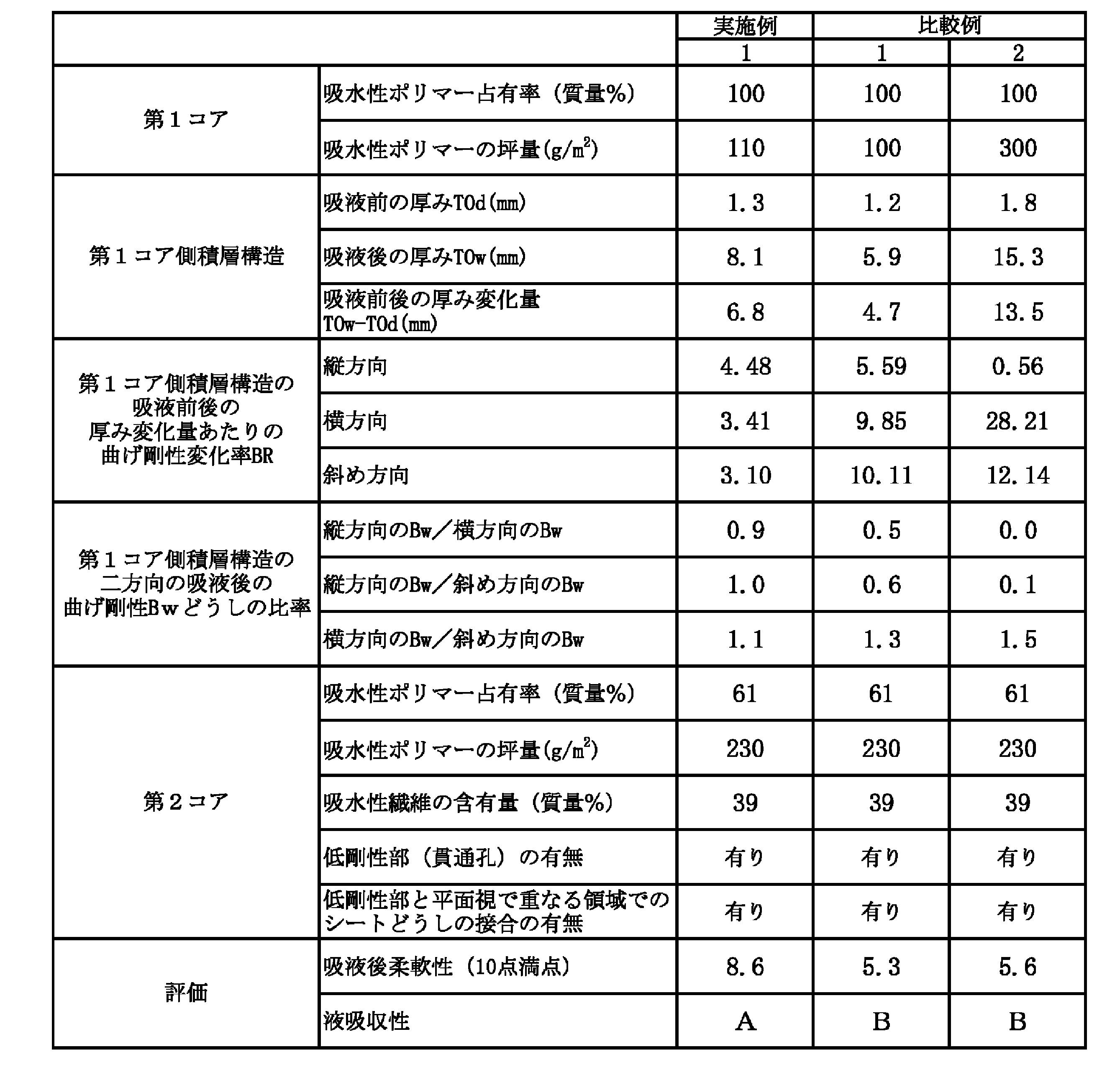
Claims (50)
- 相対向する第1シート及び第2シートと、両シート間に介在配置された中間シートとを具備し、該第1シートと該中間シートとの間に、吸水性材料として少なくとも吸水性ポリマーを含有する第1コアが介在配置され、該中間シートと該第2シートとの間に、吸水性材料として少なくとも吸水性繊維及び吸水性ポリマーを含有する第2コアが介在配置された吸収体であって、
前記第1コアの形成材料の80質量%以上が吸水性ポリマーであり、
前記第1コアは、前記第2コアに比べて、形成材料の総質量に対する吸水性ポリマーの含有質量の比率が大きく、且つ前記第1コアは、前記第2コアに比べて、吸水性ポリマーの坪量が小さく、
前記第1シート、前記第1コア及び前記中間シートからなる積層構造の、下記式(1)で算出される吸液前後の厚み変化量あたりの曲げ剛性変化率をBRとした場合、互いに直交する二方向及び該二方向と直交せずに交差する他の方向の三方向から任意に選択される二方向の該BRが、それぞれ5.0以下である、吸収体。
BR=(Bw/Bd)/T0c (1)
Bw:前記積層構造の吸液後の曲げ剛性
Bd:前記積層構造の吸液前の曲げ剛性
T0c:下記式(2)で算出される前記積層構造の吸液前後の厚み変化量
T0c=T0w-T0d (2)
T0w:前記積層構造の吸液後の4.9mN/cm2荷重下での厚み
T0d:前記積層構造の吸液前の4.9mN/cm2荷重下での厚み - 前記第1コアの形成材料の総質量に対する吸水性ポリマーの含有質量の比率が、85質量%以上である、請求項1に記載の吸収体。
- 形成材料の総質量に対する吸水性ポリマーの含有質量の比率が、前記第1コア/前記第2コアとして、1.1以上である、請求項1又は2に記載の吸収体。
- 形成材料の総質量に対する吸水性ポリマーの含有質量の比率が、前記第1コア/前記第2コアとして、5.0以下である、請求項1~3の何れか1項に記載の吸収体。
- 前記第2コアにおける、該第2コアの形成材料の総質量に対する吸水性ポリマーの含有質量の比率が、30質量%以上である、請求項1~4の何れか1項に記載の吸収体。
- 前記第2コアにおける、該第2コアの形成材料の総質量に対する吸水性ポリマーの含有質量の比率が、90質量%以下である、請求項1~5の何れか1項に記載の吸収体。
- 前記第1コアの吸水性ポリマーの坪量と前記第2コアの吸水性ポリマーの坪量との比率が、前者<後者を前提として、後者/前者として、1.1以上である、請求項1~6の何れか1項に記載の吸収体。
- 前記第1コアの吸水性ポリマーの坪量と前記第2コアの吸水性ポリマーの坪量との比率が、前者<後者を前提として、後者/前者として、10.0以下である、請求項1~7の何れか1項に記載の吸収体。
- 前記第1コアの吸水性ポリマーの坪量が、60g/m2以上である、請求項1~8の何れか1項に記載の吸収体。
- 前記第1コアの吸水性ポリマーの坪量が、700g/m2以下である、請求項1~9の何れか1項に記載の吸収体。
- 前記第2コアの吸水性ポリマーの坪量が、65g/m2以上である、請求項1~10の何れか1項に記載の吸収体。
- 前記第2コアの吸水性ポリマーの坪量が、800g/m2以下である、請求項1~11の何れか1項に記載の吸収体。
- 前記三方向から任意に選択される二方向それぞれの前記BRが、4.8以下である、請求項1~12の何れか1項に記載の吸収体。
- 前記三方向から任意に選択される二方向それぞれの前記BRが、0.1以上である、請求項1~13の何れか1項に記載の吸収体。
- 前記三方向の前記BRが、それぞれ5.0以下である、請求項1~14の何れか1項に記載の吸収体。
- 前記積層構造の一方向の吸液後の曲げ剛性Bwが、200mN・cm2/cm以下である、請求項1~15の何れか1項に記載の吸収体。
- 前記積層構造の一方向の吸液後の曲げ剛性Bwが、0.3mN・cm2/cm以上である請求項1~16の何れか1項に記載の吸収体。
- 前記吸収体が、着用者の股間部に配される吸収性物品の吸収体として使用されるものであり、
前記第1コアにおける前記吸収性物品の着用時に前記股間部に配される領域において、前記吸水性ポリマーが均一に分布している、請求項1~17の何れか1項に記載の吸収体。 - 前記三方向から任意に選択される二方向どうしの前記Bwの比率が、それぞれ0.8以上1.2以下である、請求項1~18の何れか1項に記載の吸収体。
- 前記吸収体は、平面視において一方向に長い形状を有し、該吸収体の長手方向中央を境界として、該吸収体の長手方向一方側の方が、該吸収体の長手方向他方側に比べて、前記吸水性材料が多い、請求項1~19の何れか1項に記載の吸収体。
- 前記第2コアは、前記吸収体の長手方向中央を長手方向に跨いで延在し、且つ該第2コアにおける該吸収体の長手方向一方側に位置する部分の方が、該第2コアにおける該吸収体の長手方向他方側に位置する部分に比べて、前記吸水性材料が多い、請求項20に記載の吸収体。
- 前記第2コアにおける前記吸収体の長手方向一方側に位置する部分の方が、該第2コアにおける該吸収体の長手方向他方側に位置する部分に比べて、主面の面積が大きい、請求項20又は21に記載の吸収体。
- 前記第2コアは、前記第1コアに比べて、長手方向の長さが短く、該第2コアの該長手方向の長さと該第1コアの該長手方向の長さとの比率が、前者<後者を前提として、後者/前者として、1.05以上である、請求項20~22の何れか1項に記載の吸収体。
- 前記第2コアは、前記第1コアに比べて、長手方向の長さが短く、該第2コアの該長手方向の長さと該第1コアの該長手方向の長さとの比率が、前者<後者を前提として、後者/前者として、1.7以下である、請求項20~23の何れか1項に記載の吸収体。
- 前記第2コアは、該第2コアの長手方向と直交する幅方向の長さすなわち幅が該長手方向の全長にわたって一定ではなく、相対的に幅広で主面の面積が大きい幅広部と、相対的に幅狭で主面の面積が小さい幅狭部とを該長手方向に有している、請求項20~24の何れか1項に記載の吸収体。
- 前記中間シートにおける前記第2コアの配置面の周縁部における、少なくとも前記幅狭部の前記幅方向の外方に、該第2コアが配置されずに該中間シートが露出している部分が存在し、その中間シートの露出部分にて、該中間シートと該第2シートとが接着剤を介して接合されている、請求項25に記載の吸収体。
- 前記幅広部の前記幅方向の最大長さと前記幅狭部の該幅方向の最大長さとの比率が、前者/後者として、1.1以上である、請求項25又は26に記載の吸収体。
- 前記幅広部の前記幅方向の最大長さと前記幅狭部の該幅方向の最大長さとの比率が、前者/後者として、5.5以下である、請求項25~27の何れか1項に記載の吸収体。
- 前記幅広部における前記第2コアの長手方向の長さと前記幅狭部における該第2コアの長手方向の長さとの比率が、前者/後者として、1.2以上である、請求項25~28の何れか1項に記載の吸収体。
- 前記幅広部における前記第2コアの長手方向の長さと前記幅狭部における該第2コアの長手方向の長さとの比率が、前者/後者として、7.0以下である、請求項25~29の何れか1項に記載の吸収体。
- 前記吸収体が、着用者の股間部に配される吸収性物品の吸収体として使用されるものであり、
前記吸収体は、その長手方向において吸水性材料が偏在している側、が、前記吸収性物品の腹側部寄りに位置するように配置されている、請求項1~30の何れか1項に記載の吸収体。 - 前記第2シート側が、吸収すべき液と最初に接触する受液面側として使用される、請求項1~31の何れか1項に記載の吸収体。
- 前記第1シート及び前記中間シートそれぞれの前記第1コアとの対向面に接着剤が塗布されており、
前記接着剤のうち、前記第1コアにおいて吸収すべき液と最初に接触する受液面側に塗布されたものは、その接着剤の塗布領域において塗布部と非塗布部とが混在するように塗布されており、
前記接着剤のうち、前記受液面側とは反対側に塗布されたものは、その接着剤の塗布領域において非塗布部が実質的に存在しないように塗布されている、請求項1~32の何れか1項に記載の吸収体。 - 前記中間シート側が前記受液面側であり、該中間シートの前記第1コアとの対向面に塗布された接着剤は、該接着剤の塗布領域において塗布部と非塗布部とが混在するように塗布されており、
前記第1シートの前記第1コアとの対向面に塗布された接着剤は、該接着剤の塗布領域において非塗布部が実質的に存在しないように塗布されている、請求項33に記載の吸収体。 - 前記第1コアを挟んでその両側に配された接着剤の総坪量が、3g/m2以上である、請求項33又は34に記載の吸収体。
- 前記第1コアを挟んでその両側に配された接着剤の総坪量が、50g/m2以下である、請求項33~35の何れか1項に記載の吸収体。
- 前記第1シートと前記中間シートとが、それらの一方又は両方に塗布された接着剤からなる柱状部を介して接合されている、請求項33~36の何れか1項に記載の吸収体。
- 前記第2コアは、該第2コアの形成材料が存在しないか又は周辺部よりも低坪量で存在する、低剛性部を有する、請求項1~37の何れか1項に記載の吸収体。
- 前記低剛性部は、前記第2コアの長手方向に延在しており、
前記低剛性部における前記第2コアの長手方向の長さが、該第2コアの長手方向の長さに対して、20%以上である、請求項38に記載の吸収体。 - 前記低剛性部は、前記第2コアの長手方向に延在しており、
前記低剛性部における前記第2コアの長手方向の長さが、該第2コアの長手方向の長さに対して、95%以下である、請求項38又は39に記載の吸収体。 - 前記低剛性部における前記第2コアの長手方向と直交する方向の長さが、1mm以上である、請求項38~40の何れか1項に記載の吸収体。
- 前記低剛性部における前記第2コアの長手方向と直交する方向の長さが、25mm以下である、請求項38~41の何れか1項に記載の吸収体。
- 前記低剛性部は、前記第2コアの長手方向と直交する方向の両側に一対形成されており、その一対の低剛性部どうしの間隔が、10mm以上である、請求項38~42の何れか1項に記載の吸収体。
- 前記低剛性部は、前記第2コアの長手方向と直交する方向の両側に一対形成されており、その一対の低剛性部どうしの間隔が、80mm以下である、請求項38~43の何れか1項に記載の吸収体。
- 前記低剛性部と平面視で重なる領域において、前記第2シートと前記中間シートとが接合されているとともに、該中間シートと前記第1シートとが接合されている、請求項38~44の何れか1項に記載の吸収体。
- 前記低剛性部と平面視で重なる領域の10%以上において、前記第2シートと前記中間シートとが接合されている、請求項45に記載の吸収体。
- 前記低剛性部と平面視で重なる領域の90%以下において、前記第2シートと前記中間シートとが接合されている、請求項45又は46に記載の吸収体。
- 前記第1コアにおける前記低剛性部と平面視で重なる領域において、前記吸水性ポリマーが均一に分布している、請求項38~47の何れか1項に記載の吸収体。
- JIS P 8141に準じて測定されるクレム吸水高さに関し、「前記第1シート≦前記第2シート<前記中間シート」の大小関係が成立し、且つ該中間シートの該クレム吸水高さが5分で20mm以上である、請求項1~48の何れか1項に記載の吸収体。
- 請求項1~49の何れか1項に記載の吸収体を備えた吸収性物品。
Priority Applications (4)
| Application Number | Priority Date | Filing Date | Title |
|---|---|---|---|
| CN201980102857.5A CN114786638B (zh) | 2019-12-23 | 2019-12-23 | 吸收体和吸收性物品 |
| PCT/JP2019/050270 WO2021130802A1 (ja) | 2019-12-23 | 2019-12-23 | 吸収体及び吸収性物品 |
| JP2021566386A JP7122481B2 (ja) | 2019-12-23 | 2019-12-23 | 吸収体及び吸収性物品 |
| EP19957128.2A EP4082499B1 (en) | 2019-12-23 | 2019-12-23 | Absorbent, and absorbent article |
Applications Claiming Priority (1)
| Application Number | Priority Date | Filing Date | Title |
|---|---|---|---|
| PCT/JP2019/050270 WO2021130802A1 (ja) | 2019-12-23 | 2019-12-23 | 吸収体及び吸収性物品 |
Publications (1)
| Publication Number | Publication Date |
|---|---|
| WO2021130802A1 true WO2021130802A1 (ja) | 2021-07-01 |
Family
ID=76575757
Family Applications (1)
| Application Number | Title | Priority Date | Filing Date |
|---|---|---|---|
| PCT/JP2019/050270 Ceased WO2021130802A1 (ja) | 2019-12-23 | 2019-12-23 | 吸収体及び吸収性物品 |
Country Status (4)
| Country | Link |
|---|---|
| EP (1) | EP4082499B1 (ja) |
| JP (1) | JP7122481B2 (ja) |
| CN (1) | CN114786638B (ja) |
| WO (1) | WO2021130802A1 (ja) |
Families Citing this family (1)
| Publication number | Priority date | Publication date | Assignee | Title |
|---|---|---|---|---|
| JP2024154802A (ja) * | 2023-04-19 | 2024-10-31 | 花王株式会社 | 前側パッドと後側パッドとを具備する吸収性物品 |
Citations (7)
| Publication number | Priority date | Publication date | Assignee | Title |
|---|---|---|---|---|
| WO2010076857A1 (ja) | 2008-12-29 | 2010-07-08 | 住友精化株式会社 | 吸水シート組成物 |
| JP2010529879A (ja) | 2007-06-18 | 2010-09-02 | ザ プロクター アンド ギャンブル カンパニー | 実質的に連続的に分布された吸収性の粒子状ポリマー材料を有する、改善された捕捉システムを備える使い捨て吸収性物品 |
| JP2017140461A (ja) * | 2012-12-10 | 2017-08-17 | ザ プロクター アンド ギャンブル カンパニー | 賦形された捕捉−分配システムを有する吸収性物品 |
| JP2018019953A (ja) * | 2016-08-04 | 2018-02-08 | 花王株式会社 | 吸収性物品 |
| JP2018050835A (ja) * | 2016-09-27 | 2018-04-05 | ユニ・チャーム株式会社 | 吸収性物品 |
| JP2018050987A (ja) | 2016-09-29 | 2018-04-05 | 大王製紙株式会社 | 吸収性物品 |
| JP2019146657A (ja) * | 2018-02-26 | 2019-09-05 | 日本製紙クレシア株式会社 | 男性用吸収性物品 |
Family Cites Families (8)
| Publication number | Priority date | Publication date | Assignee | Title |
|---|---|---|---|---|
| EP2565031A4 (en) * | 2010-04-30 | 2013-09-25 | Sumitomo Seika Chemicals | WATER ABSORBENT FILM STRUCTURE |
| JP6050612B2 (ja) * | 2012-06-11 | 2016-12-21 | 花王株式会社 | 吸収性物品 |
| JP5670960B2 (ja) * | 2012-06-11 | 2015-02-18 | 花王株式会社 | 吸収性物品 |
| JP6045302B2 (ja) * | 2012-10-31 | 2016-12-14 | ユニ・チャーム株式会社 | 体液処理用の吸収体の製造方法 |
| ES3014835T3 (en) * | 2014-01-31 | 2025-04-25 | Ontex Bv | Multi-layer absorbent material |
| JP6190861B2 (ja) * | 2015-11-09 | 2017-08-30 | ユニ・チャーム株式会社 | 吸収性物品 |
| EP3167858A1 (en) * | 2015-11-16 | 2017-05-17 | The Procter and Gamble Company | Absorbent cores having material free areas |
| JP6356369B1 (ja) * | 2018-03-20 | 2018-07-11 | ユニ・チャーム株式会社 | 吸収性物品 |
-
2019
- 2019-12-23 CN CN201980102857.5A patent/CN114786638B/zh active Active
- 2019-12-23 WO PCT/JP2019/050270 patent/WO2021130802A1/ja not_active Ceased
- 2019-12-23 EP EP19957128.2A patent/EP4082499B1/en active Active
- 2019-12-23 JP JP2021566386A patent/JP7122481B2/ja active Active
Patent Citations (7)
| Publication number | Priority date | Publication date | Assignee | Title |
|---|---|---|---|---|
| JP2010529879A (ja) | 2007-06-18 | 2010-09-02 | ザ プロクター アンド ギャンブル カンパニー | 実質的に連続的に分布された吸収性の粒子状ポリマー材料を有する、改善された捕捉システムを備える使い捨て吸収性物品 |
| WO2010076857A1 (ja) | 2008-12-29 | 2010-07-08 | 住友精化株式会社 | 吸水シート組成物 |
| JP2017140461A (ja) * | 2012-12-10 | 2017-08-17 | ザ プロクター アンド ギャンブル カンパニー | 賦形された捕捉−分配システムを有する吸収性物品 |
| JP2018019953A (ja) * | 2016-08-04 | 2018-02-08 | 花王株式会社 | 吸収性物品 |
| JP2018050835A (ja) * | 2016-09-27 | 2018-04-05 | ユニ・チャーム株式会社 | 吸収性物品 |
| JP2018050987A (ja) | 2016-09-29 | 2018-04-05 | 大王製紙株式会社 | 吸収性物品 |
| JP2019146657A (ja) * | 2018-02-26 | 2019-09-05 | 日本製紙クレシア株式会社 | 男性用吸収性物品 |
Non-Patent Citations (2)
| Title |
|---|
| See also references of EP4082499A4 |
| SUEO KAWABATA: "Texture Measurement and Standardization Research Committee", 10 July 1980, THE TEXTILE MACHINERY SOCIETY OF JAPAN, article "Standardization and Analysis of Texture Evaluation" |
Also Published As
| Publication number | Publication date |
|---|---|
| JPWO2021130802A1 (ja) | 2021-07-01 |
| EP4082499A1 (en) | 2022-11-02 |
| EP4082499B1 (en) | 2025-11-19 |
| JP7122481B2 (ja) | 2022-08-19 |
| CN114786638A (zh) | 2022-07-22 |
| CN114786638B (zh) | 2023-04-18 |
| EP4082499A4 (en) | 2023-08-16 |
Similar Documents
| Publication | Publication Date | Title |
|---|---|---|
| JP5848312B2 (ja) | 使い捨ておむつ | |
| JP4557914B2 (ja) | 使い捨ておむつ | |
| JP2018508269A (ja) | 三次元ベイスンを形成する吸収性物品 | |
| JP2018508265A (ja) | 三次元鉢部を形成する吸収性物品 | |
| CZ204297A3 (en) | Absorption article with arch-like curved configuration and elastic lateral edges | |
| JP2018504236A (ja) | 三次元ベイスンを形成する吸収性物品 | |
| RU160872U1 (ru) | Поглощающее изделие | |
| JP2015173751A (ja) | パンツタイプ使い捨ておむつ | |
| JP4950718B2 (ja) | 使い捨ておむつ | |
| JP2021062175A (ja) | 吸収性物品 | |
| JP7388868B2 (ja) | 吸収性物品 | |
| JP7122481B2 (ja) | 吸収体及び吸収性物品 | |
| JP7411430B2 (ja) | 吸収体及び吸収性物品 | |
| JP7289242B2 (ja) | 吸収性物品 | |
| CN116234522A (zh) | 吸收性物品 | |
| RU2790644C1 (ru) | Впитывающий элемент и впитывающее изделие | |
| RU2789888C1 (ru) | Впитывающий элемент и впитывающее изделие | |
| JP7560493B2 (ja) | 吸収性物品 | |
| JP2007215688A (ja) | 吸収体および使い捨て吸収性物品 | |
| JP6941007B2 (ja) | 吸収体および吸収性物品 | |
| RU2782916C1 (ru) | Впитывающее изделие | |
| JP7521992B2 (ja) | 吸収性物品 | |
| JP7744847B2 (ja) | 吸収性複合材及び吸収性物品 | |
| JP7405628B2 (ja) | 吸収性物品 | |
| WO2022044594A1 (ja) | 吸収性物品 |
Legal Events
| Date | Code | Title | Description |
|---|---|---|---|
| 121 | Ep: the epo has been informed by wipo that ep was designated in this application |
Ref document number: 19957128 Country of ref document: EP Kind code of ref document: A1 |
|
| ENP | Entry into the national phase |
Ref document number: 2021566386 Country of ref document: JP Kind code of ref document: A |
|
| NENP | Non-entry into the national phase |
Ref country code: DE |
|
| ENP | Entry into the national phase |
Ref document number: 2019957128 Country of ref document: EP Effective date: 20220725 |
|
| WWG | Wipo information: grant in national office |
Ref document number: 2019957128 Country of ref document: EP |