WO2021131168A1 - トラクタ - Google Patents
トラクタ Download PDFInfo
- Publication number
- WO2021131168A1 WO2021131168A1 PCT/JP2020/033620 JP2020033620W WO2021131168A1 WO 2021131168 A1 WO2021131168 A1 WO 2021131168A1 JP 2020033620 W JP2020033620 W JP 2020033620W WO 2021131168 A1 WO2021131168 A1 WO 2021131168A1
- Authority
- WO
- WIPO (PCT)
- Prior art keywords
- swing
- interlocking
- link
- link mechanism
- swings
- Prior art date
- Legal status (The legal status is an assumption and is not a legal conclusion. Google has not performed a legal analysis and makes no representation as to the accuracy of the status listed.)
- Ceased
Links
Images





Classifications
-
- A—HUMAN NECESSITIES
- A01—AGRICULTURE; FORESTRY; ANIMAL HUSBANDRY; HUNTING; TRAPPING; FISHING
- A01B—SOIL WORKING IN AGRICULTURE OR FORESTRY; PARTS, DETAILS, OR ACCESSORIES OF AGRICULTURAL MACHINES OR IMPLEMENTS, IN GENERAL
- A01B63/00—Lifting or adjusting devices or arrangements for agricultural machines or implements
- A01B63/02—Lifting or adjusting devices or arrangements for agricultural machines or implements for implements mounted on tractors
- A01B63/10—Lifting or adjusting devices or arrangements for agricultural machines or implements for implements mounted on tractors operated by hydraulic or pneumatic means
- A01B63/111—Lifting or adjusting devices or arrangements for agricultural machines or implements for implements mounted on tractors operated by hydraulic or pneumatic means regulating working depth of implements
- A01B63/112—Lifting or adjusting devices or arrangements for agricultural machines or implements for implements mounted on tractors operated by hydraulic or pneumatic means regulating working depth of implements to control draught load, i.e. tractive force
-
- A—HUMAN NECESSITIES
- A01—AGRICULTURE; FORESTRY; ANIMAL HUSBANDRY; HUNTING; TRAPPING; FISHING
- A01B—SOIL WORKING IN AGRICULTURE OR FORESTRY; PARTS, DETAILS, OR ACCESSORIES OF AGRICULTURAL MACHINES OR IMPLEMENTS, IN GENERAL
- A01B59/00—Devices specially adapted for connection between animals or tractors and agricultural machines or implements
- A01B59/04—Devices specially adapted for connection between animals or tractors and agricultural machines or implements for machines pulled or pushed by a tractor
- A01B59/042—Devices specially adapted for connection between animals or tractors and agricultural machines or implements for machines pulled or pushed by a tractor having pulling means arranged on the rear part of the tractor
- A01B59/043—Devices specially adapted for connection between animals or tractors and agricultural machines or implements for machines pulled or pushed by a tractor having pulling means arranged on the rear part of the tractor supported at three points, e.g. by quick-release couplings
-
- A—HUMAN NECESSITIES
- A01—AGRICULTURE; FORESTRY; ANIMAL HUSBANDRY; HUNTING; TRAPPING; FISHING
- A01B—SOIL WORKING IN AGRICULTURE OR FORESTRY; PARTS, DETAILS, OR ACCESSORIES OF AGRICULTURAL MACHINES OR IMPLEMENTS, IN GENERAL
- A01B59/00—Devices specially adapted for connection between animals or tractors and agricultural machines or implements
- A01B59/06—Devices specially adapted for connection between animals or tractors and agricultural machines or implements for machines mounted on tractors
- A01B59/066—Devices specially adapted for connection between animals or tractors and agricultural machines or implements for machines mounted on tractors of the type comprising at least two lower arms and one upper arm generally arranged in a triangle, e.g. three-point hitches
-
- A—HUMAN NECESSITIES
- A01—AGRICULTURE; FORESTRY; ANIMAL HUSBANDRY; HUNTING; TRAPPING; FISHING
- A01B—SOIL WORKING IN AGRICULTURE OR FORESTRY; PARTS, DETAILS, OR ACCESSORIES OF AGRICULTURAL MACHINES OR IMPLEMENTS, IN GENERAL
- A01B61/00—Devices for, or parts of, agricultural machines or implements for preventing overstrain
- A01B61/02—Devices for, or parts of, agricultural machines or implements for preventing overstrain of the coupling devices between tractor and machine
Definitions
- the present invention relates to a tractor provided with a three-point link mechanism for mounting a working device so as to be able to move up and down.
- the tractor disclosed in Japanese Patent Application Laid-Open No. 2018-042530 is provided with a three-point link mechanism, and the three-point link mechanism is swung by a hydraulic unit (“hydraulic lifting device” in the document). Will be done.
- a hydraulic unit (“hydraulic lifting device” in the document).
- the work device is attached to a three-point link mechanism and is towed by the vehicle body to perform ground work, the work device is configured to be able to move up and down according to the tow load.
- a load receiving part (“load detecting member” in the literature) that receives a traction load from the work device is provided, and the load receiving part swings according to the traction load of the work device, and the hydraulic unit has three points via a link mechanism. The amount of operation for swinging the link mechanism is transmitted.
- an interlocking swing arm (“swing member” in the literature) that can swing in conjunction with the load receiving portion is provided.
- the load receiving portion swings by a predetermined amount or more
- the interlocking swing arm swings
- the swing amount of the load receiving portion is amplified by the interlocking swing arm, and the operation sensitivity of the three-point link mechanism is improved.
- the interlocking swing arm does not swing unless the load receiving portion swings by a predetermined amount or more. That is, unless the traction load reaches a predetermined amount or more, the operating sensitivity of the three-point link mechanism does not improve. Therefore, there is room for improvement in improving the operation sensitivity.
- An object of the present invention is to provide a tractor capable of raising and lowering a work device with high sensitivity according to a traction load.
- the tractor according to the present invention includes a three-point link mechanism that is swingably connected to the rear portion of the vehicle body and mounts a work device so as to be able to move up and down, a hydraulic unit that can swing the three-point link mechanism, and the work device.
- a load receiving portion that swings according to the traction load of the working device when the ground work is performed while being pulled by the vehicle body, and the hydraulic unit for the swing operation according to the swing amount of the load receiving portion.
- a link mechanism for transmitting the amount of operation is provided, and the best side of the link mechanism is interlocked with the swing of the load receiving portion by a swinging shaft core different from the swinging shaft core of the load receiving portion.
- the interlocking rocking arm is provided, the load receiving portion is provided with a first part for pressing the interlocking rocking arm, and the interlocking rocking arm is in contact with the first part.
- a second part pressed by the first part is provided, and the contact position between the first part and the second part can be changed.
- each of the load receiving portion and the interlocking swing arm swings with a separate swing shaft core, and the contact position between the first part and the second part can be changed. Therefore, by changing the contact position, the link mechanism can amplify the swing amount of the load receiving portion. Further, since the interlocking swing arm is provided on the uppermost side of the link mechanism, the interlocking swing arm swings when the load receiving portion starts swinging. In this state, since the contact position between the first part and the second part can be changed, the link mechanism can amplify the swing amount of the load receiving part from the stage when the load receiving part starts swinging.
- the operating sensitivity of the three-point link mechanism is improved as compared with the configuration in which the interlocking swing arm does not swing unless the load receiving portion swings by a predetermined amount or more.
- a tractor capable of raising and lowering the work device with high sensitivity according to the traction load is realized.
- one of the first part and the second part is a swinging member
- the other of the first part and the second part is a plurality of swinging members capable of receiving and locking the swinging member.
- the rocking member is provided with a positioning mechanism for positioning the swing angle when engaging in the plurality of recesses, which is a locking portion in which a recess is formed.
- the combination of the swing member and the locking portion constitutes a combination of the first part and the second part, and the swing member engages in the recess of the locking portion. Further, when the swing member engages in any of the plurality of recesses, the swing angle of the swing member is held by the positioning mechanism. Therefore, the contact position between the first part and the second part is held without being displaced to an unintended position. As a result, the interlocking swing arm can more preferably amplify the swing amount of the load receiving portion.
- the positioning mechanism can position the swing member at an angle orthogonal to the swing angle of the load receiving portion.
- the angle at which the swing member is positioned includes an angle orthogonal to the swing angle of the load receiving portion. That is, the swing range of the swing member is set in a range close to the swing angle of the load receiving portion. Therefore, the swinging member can firmly receive the reaction force from the locking portion. As a result, the swinging member can suitably press the locking portion.
- the "orthogonal angle" in the present invention is not limited to a strict orthogonal angle, but also includes a substantially orthogonal angle.
- the free end portion of the swing member is provided with a pin capable of engaging with the plurality of recesses, and the plurality of recesses are arranged in succession in the locking portion. It is preferable that a common recess including the above is formed, and the pin passes through the common recess and engages with any one of the plurality of recesses.
- a plurality of recesses are formed in the common recess, and the pin of the swing member is engaged in the plurality of recesses. Further, since the pin passes through the common recess and engages with any one of the plurality of recesses, the common recess is formed as a gap space between the pin and the plurality of recesses. Therefore, when the operator changes the swing angle of the swing member, the pin can swing in the gap space of the common recess, and the swing angle changing operation becomes easier.
- the link mechanism has a sensitivity changing portion that operates so that the displacement amount of the lower side mechanism of the link mechanism increases as the load receiving portion swings to the side where the traction load is large. It is preferable that it is provided.
- the work device is positively controlled to rise in order to reduce the traction load.
- the larger the swing amount of the load receiving portion the larger the displacement amount of the lower side of the link mechanism.
- the link ratio is changed to a link ratio change rate smaller than the link ratio change rate by the first part and the second part on the lower side of the link mechanism than the interlocking swing arm. It is preferable that the part is provided.
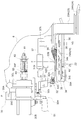
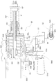
- FIG. 5 is a sectional view taken along line VV of FIG. 4 showing a link mechanism.
- FIG. 5 is a cross-sectional view taken along the line VV of FIG. 4 showing the movement of the link mechanism in comparison with FIG. 7.
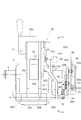
- the tractor shown in FIG. 1 includes a pair of left and right front wheels 1, a pair of left and right rear wheels 2, a front frame 3, an intermediate frame 4, a clutch housing 5, a transmission case 6, a driving unit 7, and left and right.
- a pair of rear fenders 8 and a pair are provided.
- the pair of left and right front wheels 1 are pivotally supported by the front frame 3 arranged at the front of the vehicle body, and are located laterally outside the fuselage with respect to the front frame 3.
- the intermediate frame 4 is arranged behind the front frame 3.
- a clutch housing 5 is arranged between the front frame 3 and the intermediate frame 4, and each of the front frame 3 and the intermediate frame 4 is connected to the clutch housing 5.
- the transmission case 6 is connected to the rear end portion of the intermediate frame 4.
- the clutch housing 5 and the transmission case 6 are also used as a body frame of a tractor. That is, as a vehicle body frame of the tractor, a front frame 3, an intermediate frame 4, a clutch housing 5, and a transmission case 6 are provided.
- the engine E is mounted and supported on the rear part of the front frame 3, and the clutch housing 5 is connected to the lower part of the rear end of the engine E. Further, the pair of left and right rear wheels 2 are pivotally supported by the transmission case 6 in a state of being located on the left and right outer sides of the transmission case 6.
- the clutch housing 5 has a main clutch and the like built in
- the intermediate frame 4 has a transmission shaft
- the transmission case 6 has a main transmission and an auxiliary transmission. Then, the power of the engine E is transmitted to the pair of left and right front wheels 1 and the pair of left and right rear wheels 2 via the main clutch, the transmission shaft, the main transmission, the auxiliary transmission, and the like.
- the driver unit 7 is arranged at the rear part of the vehicle body and is configured so that an operator can board.
- the driver unit 7 is provided with a steering wheel 10 and a driver's seat 11.
- the operator can be seated in the driver's seat 11.
- the steering wheel 10 is provided in front of the driver's seat 11, and the operator manually operates the steering wheel 10 to steer a pair of left and right front wheels 1.
- Rear fenders 8 are arranged on the lateral outer sides of the left and right sides of the driver's seat 11, and the rear fenders 8 cover the left and right rear wheels 2 from above.
- the transmission case 6 is arranged below the driver's seat 11.
- the driver's seat 11 is located between the pair of left and right rear wheels 2 in a plan view and a front-rear view.
- a three-point link mechanism 12 is connected to the rear part of the transmission case 6 so as to swing up and down, and the three-point link mechanism 12 is configured so that a working device 15 can be attached.
- the working device 15 shown in FIG. 1 is a plow.
- the working device 15 may be, for example, a rotary tiller, a disc halo, a cultivator, a subsoiler, or the like.
- the three-point link mechanism 12 is provided with a single top link 13 and left and right lower links 14.
- the lower link 14 is swingably connected to the lower rear portion of the transmission case 6 around the swing shaft core Y1.
- a load receiving portion 30 is connected to the rear upper portion of the transmission case 6, and a top link 13 is swingably connected to the load receiving portion 30 around the swing shaft core Y2.
- the load receiving unit 30 will be described later.
- the three-point link mechanism 12 is driven up and down by a hydraulically driven lift arm 16. Specifically, one end of the link member 19 is pivotally connected to the tip of the lift arm 16 with a pin, and the other end of the link member 19 is pivotally connected to the lower link 14 with a pin.
- the lift arm 16 is configured to be able to swing up and down around the swing axis X based on the drive of a hydraulic actuator (not shown). Then, the lower link 14 swings up and down as the lift arm 16 swings up and down.
- the top link 13 connected to the working device 15 also swings up and down in cooperation with the vertical swing of the lower link 14.
- the work device 15 is connected to the top link 13 and the lower link 14 so as to be relatively swingable, and the work device 15 moves up and down in cooperation with the vertical swing of the top link 13 and the lower link 14. .
- the three-point link mechanism 12 attaches the working device 15 so as to be able to move up and down.
- the hydraulic actuator and spool shown in the present embodiment correspond to the "hydraulic unit" of the present invention. That is, a hydraulic unit capable of swinging the three-point link mechanism 12 is provided.
- the working height of the working device 15 is configured to be adjustable based on the work load and the plowing depth of the working device 15 during ground work.
- the tractor of the present embodiment is provided with a mechanism for moving the working device 15 such as a plow up and down according to the traction load and adjusting the traction load to be constant, that is, a draft control mechanism.
- a draft control mechanism for moving the working device 15 such as a plow up and down according to the traction load and adjusting the traction load to be constant, that is, a draft control mechanism.
- a draft control mechanism will be described.
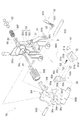
- the draft mechanism includes a load receiving portion 30, a link mechanism (interlocking swing arm 31, connecting link portion 32, plowing depth adjusting cam 34, interlocking swing portion 35, and linking rod 36. ) And are provided.
- the lift arm 16 is not shown in FIGS. 2 to 4, but the swing axis X of the lift arm 16 is shown. ..
- the load receiving unit 30 swings according to the traction load of the work device 15 when the work device 15 is towed by the vehicle body of the tractor to perform ground work.
- the link mechanism transmits the operation amount for the swing operation of the three-point link mechanism 12 to the hydraulic unit (including the hydraulic actuator and the spool (not shown above) not shown above) according to the swing amount of the load receiving portion 30.
- an interlocking swing arm 31 a connecting link portion 32, a plowing depth adjusting cam 34, an interlocking swing portion 35, and a linking rod 36 are provided.
- the load receiving portion 30 is provided with a bracket 30A, a receiving member 30B, a fulcrum pin 30C, a linking pin 30D, a first coil spring 30E, a second coil spring 30F, and a swing prohibition member 30G.
- the bracket 30A is connected and fixed to the rear portion of the transmission case 6.
- the top link 13 is connected to the receiving member 30B.
- Round holes through which the fulcrum pin 30C can be inserted are drilled laterally in the lower portion of the bracket 30A and the lower portion of the receiving member 30B, and the round holes in the lower portions of the bracket 30A and the receiving member 30B are formed in the fulcrum pin 30C.
- a round hole 30o is drilled sideways in the upper and lower central parts of the receiving member 30B. Further, a long hole 30p is formed in the upper and lower central portions of the bracket 30A in the lateral direction of the machine body. The longitudinal direction of the elongated hole 30p is along the front-rear direction of the machine body.
- the linking pin 30D penetrates the round hole 30o and the elongated hole 30p in the upper and lower central portions of the receiving member 30B. Both ends of the linking pin 30D in the longitudinal direction are located outside the receiving member 30B. Then, a snap pin is locked to the end portion in the longitudinal direction of the linking pin 30D, and the linking pin 30D is prevented from coming off with respect to the bracket 30A and the receiving member 30B.
- the linking pin 30D cannot be displaced relative to the round hole 30o and can slide along the longitudinal direction of the elongated hole 30p. From this, the receiving member 30B can swing back and forth within the range of the elongated hole 30p in the longitudinal direction.
- a storage cylinder 30L is formed on the upper part of the bracket 30A.
- the storage cylinder portion 30L is formed in a cylindrical shape facing the front and rear of the machine body.
- the first coil spring 30E is housed in the storage cylinder portion 30L (see FIG. 10).
- a gap is formed between the upper part of the bracket 30A and the upper part of the receiving member 30B.
- the first coil spring 30E is provided in this gap, and both ends of the first coil spring 30E in the extending direction come into contact with the bracket 30A and the receiving member 30B, respectively.
- the receiving member 30B is urged by the first coil spring 30E so as to swing rearward.
- the second coil spring 30F is provided on the side opposite to the side where the first coil spring 30E is located with respect to the bracket 30A.
- the elastic modulus of the second coil spring 30F is smaller than the elastic modulus of the first coil spring 30E.
- Three upper and lower mounting holes 30s are drilled in the rear portion of the bracket 30A, and one end of the top link 13 is connected to one of the plurality of mounting holes 30s so as to be vertically swingable via a pin. Of the three upper and lower mounting holes 30s, the portion connected to the top link 13 is the swing axis Y2 of the top link 13.
- the end of the top link 13 on the side opposite to the side connected to the bracket 30A is connected to the upper part of the working device 15. Therefore, a tensile force acts on the top link 13 from the work device 15 when the work device 15 is raised or when the work device 15 is not performing ground work. Further, in this state, a tensile force acts on the receiving member 30B from the top link 13, and the receiving member 30B swings to the rearmost side.
- the receiving member 30B When the receiving member 30B swings forward, the first coil spring 30E contracts. The elastic force of the first coil spring 30E increases in proportion to the amount of contraction of the first coil spring 30E. Therefore, the front side of the receiving member 30B has a swing angle at which the pressing force acting on the receiving member 30B due to the traction load of the working device 15 and the resultant force of the elastic forces of the first coil spring 30E and the second coil spring 30F are balanced. The swing to stops. From this, as the traction load due to the ground work of the work device 15 increases, the pressing force acting on the receiving member 30B increases, so that the receiving member 30B swings further forward. As a result, the receiving member 30B is configured to be able to detect the traction load of the working device 15.
- the swing prohibition member 30G is a member that prohibits the swing of the receiving member 30B.
- the swing prohibition member 30G is configured to swing around the swing axis V (see FIG. 4) in the front-rear direction provided in the upper left portion of the bracket 30A.
- a handle is provided on the upper part of the swing prohibition member 30G.
- a horizontal plate portion that can be interposed in a region between the upper end portion of the bracket 30A and the upper end portion of the receiving member 30B is formed between the swing shaft core V and the handle. When the operator operates the handle left and right, the horizontal plate portion swings up and down.
- the swing prohibition member 30G swings clockwise in FIG.
- the horizontal plate portion is the upper end portion of the bracket 30A and the upper end portion of the receiving member 30B. It intervenes over the entire area of the gap between the and, and regulates the swing of the receiving member 30B to the front side. As a result, the receiving member 30B cannot swing.
- the swing prohibition member 30G swings counterclockwise in FIG. 4, the horizontal plate portion is separated from the region between the upper end portion of the bracket 30A and the upper end portion of the receiving member 30B, and the receiving member 30B is moved. You will be able to swing back and forth.
- the load receiving unit 30 is provided with an amplification adjusting unit 30H. Further, the interlocking swing arm 31 is pivotally connected to the bracket 30A with a pin so that it can swing back and forth. The interlocking swing arm 31 is provided on the most skillful side of the link mechanism. The interlocking swing arm 31 is connected to the right side of the bracket 30A so that it can swing back and forth around the swing axis Q1 in the lateral direction of the machine body.
- the amplification adjusting unit 30H is bolted to the right side of the receiving member 30B. The interlocking swing arm 31 swings in conjunction with the swing of the load receiving portion 30 at a swing shaft core Q1 different from the swing shaft core P of the load receiving portion 30.
- the amplification adjusting unit 30H swings integrally with the receiving member 30B, and when the receiving member 30B swings forward, the interlocking swing arm 31 and the amplification adjusting unit 30H come into contact with each other, and the interlocking swing arm 31 swings. ..
- the interlocking swing arm 31 is configured to be able to amplify the swing amount of the receiving member 30B by swinging more than the front-back swing of the receiving member 30B.
- the amplification adjusting unit 30H is configured so that the swing amount of the interlocking swing arm 31 can be adjusted.
- a contact bolt 30k is connected to the front upper portion of the receiving member 30B with respect to the amplification adjusting portion 30H.
- the contact bolt 30k and the interlocking rocking arm 31 come into contact with each other, and the interlocking rocking arm 31 and the amplification adjusting unit 30H are separated from each other.
- the receiving member 30B swings forward, the interlocking swing arm 31 swings around the swing axis Q1 in a state where the contact bolt 30k and the interlocking swing arm 31 are in contact with each other.
- the separation distance between the interlocking swing arm 31 and the amplification adjusting unit 30H becomes smaller.
- the receiving member 30B swings further forward and the interlocking swing arm 31 and the amplification adjusting unit 30H come into contact with each other, the contact bolt 30k and the interlocking swing arm 31 are separated from each other.
- the lift arm 16 swings up and down by supplying and discharging hydraulic oil to the hydraulic actuator, and the supply and discharge of hydraulic oil is controlled by the operation of a spool (not shown).
- a spool (not shown).
- Each of the connecting link portion 32, the plowing depth adjusting cam 34, the interlocking swing portion 35, and the linking rod 36 is a link mechanism for transmitting the swinging motion of the receiving member 30B to the spool.
- one end of the connecting link portion 32 is pivotally connected to the lower end of the interlocking swing arm 31 by a pin member 33 so as to be able to swing relative to each other.
- the plowing depth adjusting cam 34 is pivotally connected to the end with a pin so that it can swing relative to each other.
- a support member 37 is connected to the right side of the transmission case 6, and two cylindrical members 37A and 37B project laterally and outwardly from the support member 37.
- the plowing depth adjusting cam 34 is supported by the cylindrical member 37B so that it can swing back and forth around the swing axis Z1 in the lateral direction of the machine body.
- the connecting link portion 32 includes a first link member 32A, a second link member 32B, a coil spring member 32C, and a connecting pin 32D.
- the first link member 32A is formed by welding a flat plate member and a bolt member. One end of each of the flat plate member and the bolt member in the longitudinal direction is connected by welding. Of the flat plate members of the first link member 32A, the ends on the side opposite to the side welded to the bolt member are pivotally connected to the second link member 32B by the connecting pin 32D so as to be relatively swingable.
- the second link member 32B is a flat plate member. Of the second link member 32B, the end portion on the side opposite to the side pivotally connected to the first link member 32A is pivotally connected to the plowing depth adjusting cam 34 with a pin so as to be relatively swingable.
- a pair of nuts are locked in the upper and lower end regions of the bolt member of the first link member 32A, and the coil spring member 32C and the pin member 33 are extrapolated between the pair of nuts.
- the coil spring member 32C is arranged above the pin member 33, that is, on the side where the second link member 32B is located.
- the pin member 33 is fitted onto the bolt member of the first link member 32A and is inserted into one of a plurality of insertion holes 31h formed at the lower end of the interlocking swing arm 31 so as not to come out of the insertion hole 31h. It is fastened with a snap pin. That is, the lower end of the bolt member in the first link member 32A and the lower end of the interlocking swing arm 31 are swingably connected by the pin member 33.
- the tension spring 38 is hooked on the plowing depth adjusting cam 34, and the other end of the tension spring 38 is hooked on the hook member 39.
- the hook member 39 is supported by the cylindrical member 37A.
- the cylindrical member 37A is located on the front side of the machine body with respect to the plowing depth adjusting cam 34, and the tension spring 38 tensions the plowing depth adjusting cam 34 and the cylindrical member 37A. Therefore, the plowing depth adjusting cam 34 is urged to swing forward.
- the lower end of the swing arm 23A of the height setting lever 23 and the lower end of the swing arm 24A of the plowing lever 24 are fitted onto the cylindrical member 37A.
- the longitudinal direction of the cylindrical member 37A extends along the swing axis Y3 in the lateral direction of the machine body.
- Each of the lower end portion of the swing arm 23A and the lower end portion of the swing arm 24A is a swing base end portion. That is, the height setting lever 23 and the plowing depth lever 24 can swing back and forth around the swing axis Y3.
- a cam portion 34a is formed on the plowing depth adjusting cam 34. Further, a roller 35A is provided in the central region of the interlocking rocking portion 35 in the longitudinal direction so that the cam portion 34a and the roller 35A can come into contact with each other.
- the cam portion 34a is inclined so as to be separated from the swing shaft core Z1 toward the front side. From this, when the front side region of the cam portion 34a and the roller 35A come into contact with each other, the degree of swinging of the interlocking rocking portion 35 is higher than that when the rear side region of the cam portion 34a and the roller 35A come into contact with each other. growing.
- the plowing depth adjusting cam 34 corresponds to the "sensitivity changing unit" of the present invention.
- a connecting portion 34b for the control cable of the rotary tilling device is formed on the tilling depth adjusting cam 34, and one end of the control cable can be connected to the connecting portion 34b.
- the control cable of the rotary tillage device is described in FIGS. 16 and 17 of JP-A-2018-042530.
- the connecting portion 34b is located on the side opposite to the side where the cam portion 34a is located with the interlocking swing portion 35 interposed therebetween.
- the connecting portion 34b is pulled via the control cable by the vertical swing of the grounding body provided in the rotary tillage device, and the tillage depth adjustment cam 34 swings back and forth.
- the swing prohibition member 30G is generally swinged downward, and the swinging of the receiving member 30B to the front side is restricted.
- the first link member 32A and the second link member 32B are configured to be flexible via the connecting pin 32D, the receiving member 30B cannot swing. Even so, the plowing depth adjusting cam 34 can swing.
- a plurality of insertion holes 35h are formed at the free end of the interlocking rocking portion 35, and the rear end of the linking rod 36 is pivotally connected to one of the plurality of insertion holes 35h with a pin.
- the linking rod 36 is displaced rearward.
- a link mechanism that operates a spool that adjusts the amount of hydraulic oil supplied and discharged is connected to the front end of the linking rod 36, and when the linking rod 36 is displaced rearward, the spool is operated and the hydraulic oil is hydraulically charged. It is supplied to the actuator and the lift arm 16 swings upward.
- the swing base end portion of the interlocking swing portion 35 is pivotally connected to the free end portion of the bracket 24B with a pin so as to be swingable, and the interlocking swing portion 35 can swing back and forth around the swing shaft core Z2. ..
- the swing base ends of the swing arm 24A and the bracket 24B are connected by welding.
- the plowing depth adjusting cam 34 can come into contact with the swing arm 24A.
- the cam portion 34a and the roller 35A come close to each other, and the interlocking swing portion 35 is easily swung backward. That is, when the plowing depth adjusting cam 34 is swung rearward, the lift arm 16 is likely to be swung upward.
- the torsion spring 40 is wound around the swinging portion of the interlocking swinging portion 35.
- the torsion spring 40 is locked to a downward portion at the swing base end portion of the interlocking swing portion 35 and a downward portion at the free end portion of the bracket 24B, respectively.
- the interlocking swing portion 35 is urged to swing forward by the torsion spring 40.
- the interlocking rocking arm 31 comes into contact with the contact bolt 30k or the amplification adjusting unit 30H, and the interlocking rocking arm 31 is shown in FIGS. 7 and 8. It swings clockwise in the side view of.
- the connecting link portion 32 is pulled to the rear side in conjunction with the swinging of the interlocking swing arm 31.
- a tensile force acts from the connecting link portion 32 to the plowing depth adjusting cam 34.
- the connecting link portion 32 is displaced rearward and the plowing depth adjusting cam 34 swings rearward.
- the cam portion 34a and the roller 35A approach each other. Then, when the cam portion 34a and the roller 35A come into contact with each other, the interlocking swing portion 35 swings backward while the roller 35A moves along the cam portion 34a. Then, the linking rod 36 oscillatingly connected to the interlocking swing portion 35 is pulled and displaced rearward. Then, the spool is moved to supply hydraulic oil to the hydraulic actuator, and the lift arm 16 swings upward in conjunction with the swing of the interlocking swing portion 35, so that the position of the work device 15 rises.
- the receiving member 30B stands still at the rearmost end of the front-back swing range based on the front-back length of the elongated hole 30p.
- the plowing depth adjusting cam 34 is the interlocking swing arm 31. It does not work with rocking.
- the coil spring member 32C is externally attached to the first link member 32A in the connecting link portion 32.
- the interlocking swing arm 31 is configured to be able to amplify the swing amount of the receiving member 30B. Further, the amplification adjustment unit 30H is bolted to the receiving member 30B, and the amplification adjustment unit 30H and the interlocking swing arm 31 can be brought into contact with each other.
- the interlocking swing arm 31 extends up and down.
- the contact point between the amplification adjusting unit 30H and the interlocking swing arm 31 in the vertical direction is changed, the swing amount of the interlocking swing arm 31 changes even if the swing amount of the receiving member 30B is the same.
- the amplification adjusting unit 30H is configured so that the contact point with respect to the interlocking swing arm 31 can be adjusted in the vertical direction.
- the amplification adjusting unit 30H is provided with a bracket member 50 and a swing member 51.
- An elongated hole 50a is formed in each of the upper end portion and the lower end portion of the flat surface portion of the bracket member 50, and the pair of upper and lower elongated holes 50a extend in the vertical direction.
- Bolts are inserted through a pair of upper and lower elongated holes 50a. That is, the bracket member 50 is bolted to the receiving member 30B so that the vertical positioning can be adjusted.
- a projecting columnar portion 50b is formed in a region between a pair of upper and lower elongated holes 50a, and the projecting columnar portion 50b projects to the side opposite to the side where the receiving member 30B is located.
- a screw groove that can be engaged with a nut is formed at the protruding tip of the protruding cylindrical portion 50b.
- the swing member 51 is configured to swing relative to the bracket member 50.
- a bolt insertion hole 51b is formed in the swing base end of the swing member 51.
- the protrusion cylinder portion 50b is inserted into the bolt insertion hole 51b, and the nut engages with the tip portion of the protrusion cylinder portion 50b.
- the swing member 51 is configured to swing up and down around the swing shaft core Q2.
- the rocking member 51 corresponds to the "first part" in the present invention. That is, the load receiving portion 30 is provided with a swing member 51 as a first portion for pressing the interlocking swing arm 31.
- An engagement pin 51a is provided at the free end of the swing member 51.
- the engagement pin 51a is formed in a columnar shape extending in the lateral direction of the machine body.
- the engagement pin 51a may be welded and fixed to the free end portion of the swing member 51, or may be bolted to the free end portion of the swing member 51.
- the engagement pin 51a corresponds to the "pin" of the present invention.
- the interlocking rocking arm 31 is provided with a "second part” that comes into contact with the rocking member 51 as the first part and is pressed by the rocking member 51.
- the second part is the locking part 52.
- the locking portion 52 is formed with a plurality of recesses capable of receiving and locking the swing member 51.
- a “plurality of recesses” a state in which the first recessed portion 52a, the second recessed portion 52b, and the third recessed portion 52c are vertically arranged on the portion of the interlocking swing arm 31 above the swing shaft core Q1. It is provided in.
- the first recessed portion 52a is the farthest from the swinging shaft core Q1
- the third recessed portion 52c is the closest to the swinging shaft core Q1.
- Each of the first recessed portion 52a, the second recessed portion 52b, and the third recessed portion 52c is formed so as to be curved in an arc shape corresponding to the cylindrical engaging pin 51a.
- each of the first recessed portion 52a, the second recessed portion 52b, and the third recessed portion 52c is configured to accept and lock the engagement pin 51a. That is, the engagement pin 51a can engage with the first recessed portion 52a, the second recessed portion 52b, and the third recessed portion 52c, respectively.
- a pair of upper and lower protruding portions 52d and 52e are formed in the upper portion of the first recessed portion 52a and the lower portion of the third recessed portion 52c, respectively, and the pair of upper and lower protruding portions 52d. , 52e project from other parts of the interlocking swing arm 31 toward the position of the swing member 51.
- the engagement pin 51a is located between the pair of upper and lower protruding portions 52d and 52e, and the engagement pin 51a can swing around the swing axis Q2 within the vertical range of the pair of upper and lower protruding portions 52d and 52e. It has become.
- the first recessed portion 52a, the second recessed portion 52b, and the third recessed portion 52c are provided between the pair of upper and lower protruding portions 52d and 52e in a vertically aligned state.
- the region surrounded by the pair of upper and lower protruding portions 52d and 52e, the first recessed portion 52a, the second recessed portion 52b, and the third recessed portion 52c like a cove is the "common recessed portion" of the present invention.
- a common recess including the plurality of recesses is formed in the locking portion 52 so that the plurality of recesses are continuously arranged. Then, the engagement pin 51a passes through the common recess and engages with any one of the plurality of recesses.
- the swing member 51 When the swing member 51 swings up and down, the swing member 51 is in a state where the engagement pin 51a and the first recessed portion 52a can be engaged with each other, and the engagement pin 51a and the second recessed portion 52b are engaged with each other. It is configured to be switchable between an engageable state and a state in which the engagement pin 51a and the third recessed portion 52c can be engaged. In this way, the contact position between the swing member 51 as the first part and the locking part 52 as the second part can be changed.
- the swing member 51 is provided with a "positioning mechanism" for positioning the swing angle when engaging with any of the first recessed portion 52a, the second recessed portion 52b, and the third recessed portion 52c.
- the positioning mechanism of this embodiment is a detent mechanism.
- the positioning mechanism includes a ball 51o, a coil spring member 51p, and detent recesses 50p, 50q, 50r.
- the handle arm 51c is connected to the swing member 51 at a position adjacent to the engagement pin 51a on the side where the bolt insertion hole 51b is located.
- the handle arm 51c projects to the side opposite to the side where the receiving member 30B is located.
- the handle 51d is backwardly connected to the protruding tip of the handle arm 51c.
- the handle arm 51c is formed in a cylindrical shape. As shown in FIG. 10, a cylindrical hole is formed inside the handle arm 51c along the longitudinal direction of the handle arm 51c, and a ball 51o for a detent mechanism and a coil spring member 51p are inserted into the cylindrical hole. Has been done. As shown in FIGS. 9 and 10, detent recesses 50p, 50q, and 50r are formed at three positions along the swing trajectory of the handle arm 51c in the bracket member 50. The ball 51o for the detent mechanism engages with any of the detent recesses 50p, 50q, and 50r. When the ball 51o engages with the detent recess 50p, the engagement pin 51a and the first recess 52a can be engaged with each other.
- the swing member 51 is configured to swing up and down in three stages.
- the positioning mechanism in the present embodiment can position the swing member 51 at an angle orthogonal to the swing angle of the load receiving portion 30.
- a straight line extending over the swinging shaft core P and the swinging shaft core Q2 a straight line extending over the center of the engagement pin 51a and the swinging shaft core Q2 in the side view of the machine body, are orthogonal or substantially orthogonal (see FIG. 12). That is, the angle at which the swing member 51 is positioned (the swing angle at which the positioning mechanism positions the swing member 51) includes an angle orthogonal to the swing angle of the load receiving portion 30.
- the detent recess 50p and the detent recess 50r are respectively arranged vertically with respect to the detent recess 50q. Therefore, the swing member 51 can firmly receive the reaction force from the locking portion 52.
- the receiving member 30B stands still at the rearmost end of the front-back swing range based on the front-back length of the elongated hole 30p.
- the interlocking swing arm 31 is in contact with the contact bolt 30k of the receiving member 30B and is separated from the swing member 51. Therefore, when the pressing force does not act on the receiving member 30B, the operator can easily switch the swing member 51 to the above-mentioned three stages.
- the interlocking swing arm 31 swings at first due to the contact between the contact bolt 30k and the interlocking swing arm 31.
- the receiving member 30B swings around the swing shaft core P, and the interlocking swing arm 31 swings around the swing shaft core Q1.
- the separation distance between the swing member 51 and the swing shaft core P is larger than the distance between the first recessed portion 52a, the second recessed portion 52b, and the third recessed portion 52c and the swing shaft core Q1. .. From this, when the receiving member 30B swings forward while the contact bolt 30k and the interlocking swing arm 31 are in contact with each other, the first recessed portion 52a, the second recessed portion 52b, and the third recessed portion 52c are respectively.
- the displacement amount of is smaller than the displacement amount of the swing member 51. Therefore, when the receiving member 30B swings forward while the contact bolt 30k and the interlocking swing arm 31 are in contact with each other, the engagement pin 51a has the first recessed portion 52a, the second recessed portion 52b, and the third recessed portion. Approach each of the entrance 52c. Then, when the engagement pin 51a comes into contact with any of the first recessed portion 52a, the second recessed portion 52b, and the third recessed portion 52c, the contact bolt 30k and the interlocking swing arm 31 are separated from each other.
- the contact point between the swing member 51 and the interlocking swing arm 31 is any of the first recessed portion 52a, the second recessed portion 52b, and the third recessed portion 52c. Even if the swing amount of the receiving member 30B is the same, the swing amount of the interlocking swing arm 31 changes.
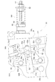
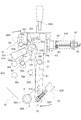
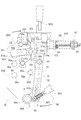
- FIG. 11 shows the contact state between the engagement pin 51a and the first recessed portion 52a.
- FIG. 12 shows the contact state between the engagement pin 51a and the second recessed portion 52b.
- FIG. 13 shows the contact state between the engagement pin 51a and the third recessed portion 52c.
- the swing prohibition member 30G has already been operated in a state where the swing of the receiving member 30B is not regulated.
- the second recessed portion 52b is closer to the swing shaft core Q1 than the first recessed portion 52a. Therefore, as shown in FIG. 12, the swing amount (indicated by D2) of the interlocking swing arm 31 when the engagement pin 51a and the second recessed portion 52b are in contact with each other is different from that of the engagement pin 51a. It is larger than the swing amount (indicated by D1) of the interlocking swing arm 31 when it comes into contact with the first recessed portion 52a. Therefore, when the engagement pin 51a and the second recessed portion 52b are in contact with each other, the top link 13 swings up and down more than when the engagement pin 51a and the first recessed portion 52a are in contact with each other.
- the third recessed portion 52c is closer to the swing shaft core Q1 than the second recessed portion 52b. Therefore, as shown in FIG. 13, the swing amount (indicated by D3) of the interlocking swing arm 31 when the engagement pin 51a and the third recessed portion 52c come into contact with each other is different from that of the engagement pin 51a. It is larger than the swing amount (indicated by D2) of the interlocking swing arm 31 when it comes into contact with the second recessed portion 52b. Therefore, when the engagement pin 51a and the third recessed portion 52c come into contact with each other, the top link 13 swings up and down more than when the engagement pin 51a and the second recessed portion 52b come into contact with each other. As described above, the more the front-back swing of the receiving member 30B is amplified, the larger the lift arm 16 swings up and down.
- the angular velocity and the angular acceleration when the interlocking swing arm 31 swings also change in proportion to the change in the swing amount of the interlocking swing arm 31. That is, the angular velocity and angular acceleration of the interlocking swing arm 31 when the engagement pin 51a and the second recessed portion 52b are in contact with each other are the interlocking rocking arm when the engagement pin 51a and the first recessed portion 52a are in contact with each other. It is faster than the angular velocity and acceleration of 31.
- the angular velocity and angular acceleration of the interlocking swing arm 31 when the engagement pin 51a and the third recessed portion 52c are in contact with each other are the interlocking rocking arm when the engagement pin 51a and the second recessed portion 52b are in contact with each other. It is faster than the angular velocity and acceleration of 31.
- the angular velocity and the angular acceleration of the interlocking swing arm 31 become faster, the angular velocity and the angular acceleration when the plowing depth adjusting cam 34 and the interlocking swing portion 35 swing become faster.
- the link ratio between the receiving member 30B and the interlocking swing arm 31 can be changed by changing the contact portion between the swing member 51 and the locking portion 52.
- four insertion holes 31h are formed at the lower end of the interlocking rocking arm 31, and three insertion holes 35h are formed at the free end of the interlocking rocking portion 35.
- the insertion hole 31h corresponds to the "link ratio changing portion" of the present invention.
- the insertion hole 35h also corresponds to the "link ratio changing portion" of the present invention.
- One of the four insertion holes 31h is selected, and the pin member 33 is inserted into this one location.
- the selected portion of the insertion hole 31h changes, the amount of displacement of the connecting link portion 32 changes, and the amount of displacement of the connecting link portion 32 increases as the insertion hole 31h on the lower side changes.
- the link ratio between the interlocking swing arm 31 and the connecting link portion 32 is configured to be changeable by the four insertion holes 31h.
- the receiving member 30B and the interlocking swing arm The rate of change of the link ratio with 31 is defined as the rate of change of the first link ratio.
- the second link ratio change rate is smaller than the first link ratio change rate.
- the link ratio between the interlocking swing portion 35 and the interlocking rod 36 is configured to be changeable by the three insertion holes 35h.
- the rate of change in the link ratio between the interlocking swing portion 35 and the linking rod 36 when the connecting point with the linking rod 36 is changed to the adjacent insertion hole 35h among the three insertion holes 35h is the third. It is defined as the rate of change in the link ratio.
- the third link ratio change rate is smaller than the first link ratio change rate described above.
- the second coil spring 30F is provided on the side opposite to the side where the first coil spring 30E is located with respect to the bracket 30A.
- the mounting structure of the second coil spring 30F will be described.
- a storage cylinder portion 30L is formed on the upper portion of the bracket 30A, and the first coil spring 30E is stored in the storage cylinder portion 30L.
- a front-rear through hole 30q is formed at a radial center portion in the front portion of the storage cylinder portion 30L.
- a hollow boss member 60 is connected to the front portion of the storage cylinder portion 30L.
- a screw groove is formed on the outer periphery of the front portion of the boss member 60, and the nut 63 engages with the screw groove.
- a spacer is provided between the rear end portion of the boss member 60 and the nut 63, and this spacer may be composed of a plurality of washers (flat washers or spring washers).
- the nut 63 projects forward from the bracket 30A, and the position of the nut 63 is adjusted by the spacer.
- the front-rear position of the nut 63 may be adjustable according to the length of the second coil spring 30F.
- the nut 63 and the spacer may be integrated, or the nut 63 may be a double nut without the spacer provided.
- the boss member 60 and the nut 63 may be integrally formed as one member, or a screw groove may not be formed on the outer periphery of the front portion of the boss member 60.
- a protrusion 30t protruding forward is welded and fixed to the region of the receiving member 30B where the first coil spring 30E abuts, and the rod 61 is pivotally connected to the protrusion 30t so as to swing up and down.
- the rod 61 penetrates the inner peripheral space of the first coil spring 30E.
- the rod 61 penetrates the hollow hole of the boss member 60 in the through hole 30q, and the protruding tip portion of the rod 61 projects to the front side of the bracket 30A.
- the second coil spring 30F is extrapolated to the rod 61 on the front side of the machine body with respect to the bracket 30A.
- a flat washer 62 having a diameter larger than the outer diameter of the second coil spring 30F is externally inserted into the rod 61 at the end of the second coil spring 30F on the side opposite to the side where the receiving member 30B is located.
- a screw groove is formed at the protruding tip of the rod 61.
- Both sides of the flat washer 62 are nut-tightened, and the flat washer 62 is sandwiched between a pair of nuts.
- the front-rear position of the flat washer 62 may be adjustable according to the length of the second coil spring 30F.
- the nut 63 is formed so as to have an opposite side diameter larger than the outer diameter of the second coil spring 30F. That is, both ends of the second coil spring 30F in the extending direction come into contact with the nut 63 and the flat washer 62, respectively.
- the thread groove portion of the boss member 60 and the nut holding the flat washer 62 are formed so as to have an outer diameter slightly smaller than the inner diameter of the second coil spring 30F. Therefore, the thread groove portion of the boss member 60 and the nut holding the flat washer 62 come into contact with the inner peripheral portion of the second coil spring 30F without rattling.
- the rod 61 displaces back and forth while swinging relative to the receiving member 30B. At this time, since the rod 61 is displaced in the vertical direction as the receiving member 30B swings, it is necessary to prevent the rod 61 from interfering with the inner peripheral surface portion of the hollow hole of the boss member 60. Therefore, the hollow hole of the boss member 60 is formed to have a diameter sufficiently larger than the cross-sectional diameter of the rod 61.
- the separation distance between the bracket 30A and the receiving member 30B changes, and the nut 63 supported by the bracket 30A and the flat washer 62 supported by the receiving member 30B via the rod 61.
- the separation distance of also changes.
- the first coil spring 30E expands and contracts.
- the rod 61 is displaced back and forth, and the separation distance between the nut 63 and the flat washer 62 changes, so that the second coil spring 30F expands and contracts.
- the second coil spring 30F contracts and the elastic energy of the second coil spring 30F increases.
- the elastic energy of the first coil spring 30E is released at once. Therefore, the receiving member 30B swings forward and backward based on the front-back length of the elongated hole 30p. It is conceivable that there is a sudden swing to the end of the moving range. Even in such a case, as the receiving member 30B swings backward, the second coil spring 30F contracts, and elastic energy is stored in the second coil spring 30F.
- the rapid extension of the first coil spring 30E is suppressed.
- the impact when the linking pin 30D comes into contact with the rearmost end of the elongated hole 30p is alleviated.
- chattering of the receiving member 30B due to the contact is suppressed.
- the load receiving portion 30 is provided with the swing member 51 as the "first part", and the interlocking swing arm 31 is provided with the locking portion 52 as the "second part".
- the present invention is not limited to this embodiment.
- the load receiving portion 30 may be provided with a locking portion 52, and the interlocking swing arm 31 may be provided with a swing member 51.
- one of the first part and the second part is a swing member 51, and the other of the first part and the second part is formed with a plurality of recesses capable of receiving and locking the swing member 51. It may be the locking portion 52.
- the locking portion 52 as the "second part” is configured as a part of the interlocking swing arm 31, but the interlocking swing arm 31 and the locking portion 52 are separate bodies. It may be configured as.
- the load receiving portion 30 is provided with the swinging member 51 as the "first part", but the first part does not have to be a swinging member, for example, an engagement pin.
- the structure may be such that 51a slides up and down. That is, it suffices that the contact positions between the "part 1" and the "part 2" can be changed.
- the connecting link portion 32 shown in the above-described embodiment includes, but is not limited to, the first link member 32A, the second link member 32B, the coil spring member 32C, and the connecting pin 32D. ..
- the connecting link portion 32 may be composed of a chain or a wire. That is, the chain or wire as the connecting link portion 32 may be pulled by the interlocking swing arm 31 to be tense, and the chain or wire may pull the tillage depth adjusting cam 34 to swing.
- the chain or wire loosens. Therefore, similarly to the above-described embodiment, even if the interlocking swing arm 31 swings, the plowing depth adjusting cam 34 does not interlock with the swing of the interlocking swing arm 31.
- the locking portion 52 as the "second portion” is formed with three recesses (first recessed portion 52a, second recessed portion 52b, third recessed portion 52c).
- the number of "plurality of recesses” may be two or four or more.
- the locking portion 52 may not have a recess, and the locking portion 52 has a flat surface portion so that the contact position between the rocking member 51 and the flat surface portion of the locking portion 52 can be changed. May be done.
- a pair of upper and lower protruding portions are formed in each of the upper portion of the first recessed portion 52a and the lower portion of the third recessed portion 52c, and between the pair of upper and lower protruding portions.
- the first recessed portion 52a, the second recessed portion 52b, and the third recessed portion 52c are provided so as to be arranged vertically to form a "common recess", but the present invention is not limited to this embodiment.
- the "common recess” does not have to be formed, and a pair of upper and lower protruding portions are not formed in the upper portion of the first recessed portion 52a and the lower portion of the third recessed portion 52c, respectively, and simply a plurality of protruding portions are not formed.
- the recesses may be arranged in a row along the longitudinal direction of the interlocking swing arm 31.
- the "common recess” may be formed as one recess corresponding to the swing range of the swing member 51.
- the receiving member 30B swings back and forth, but the receiving member 30B may swing up and down.
- the interlocking rocking arm 31 may extend in the front-rear direction of the machine body, and a plurality of recesses may be arranged along the longitudinal direction of the interlocking rocking arm 31.
- insertion holes 31h are formed at the lower end of the interlocking rocking arm 31, and three insertion holes 35h are formed at the free end of the interlocking rocking portion 35.
- One of the insertion hole 31h and the insertion hole 35h may be provided at a plurality of locations, and the other of the insertion hole 31h and the insertion hole 35h may be provided at only one location. Further, the number of insertion holes 31h and 35h can be changed as appropriate.
- the engagement pin 51a is a convex portion between the first recessed portion 52a and the second recessed portion 52b.
- the interlocking swing arm 31 may swing slightly due to contact with the convex portion between the second recessed portion 52b and the third recessed portion 52c. Even in such a case, the first link member 32A and the second link member 32B in the connecting link portion 32 are loosened so as to be swingable from each other and are not pulled straight. That is, even if the interlocking swing arm 31 swings slightly due to the swing of the swing member 51 by the work vehicle, it does not interlock with the swing of the interlocking swing arm 31 due to the play of the connecting link portion 32.
- the engagement pin 51a is a convex portion between the first recessed portion 52a and the second recessed portion 52b, or a second recessed portion 52b. It may be configured so as not to come into contact with the convex portion between the third recessed portion 52c and
- the present invention can be applied to a tractor equipped with a three-point link mechanism for mounting a working device so as to be able to move up and down.
Landscapes
- Life Sciences & Earth Sciences (AREA)
- Engineering & Computer Science (AREA)
- Mechanical Engineering (AREA)
- Soil Sciences (AREA)
- Environmental Sciences (AREA)
- Zoology (AREA)
- Lifting Devices For Agricultural Implements (AREA)
- Agricultural Machines (AREA)
Abstract
Description
本実施形態では、作業装置15の作業高さは、作業装置15の対地作業時の作業負荷や耕深に基づいて調整可能に構成されている。例えば3点リンク機構12に作業装置15としてプラウが連結された場合、プラウによる対地作業が行われる際に、プラウは地面から反力を受け、この反力が牽引負荷となる。牽引負荷が大きくなり過ぎるとプラウが破損したりエンジンEがストールしたりする虞がある。このため、プラウ等の作業装置15を牽引負荷に応じて上下昇降し、牽引負荷を一定に調整する機構、即ちドラフト制御機構が、本実施形態のトラクタに備えられている。以下、ドラフト制御機構に関して説明する。
上述したように、連動揺動アーム31は受け部材30Bの揺動量を増幅可能に構成されている。また、増幅調整部30Hが受け部材30Bにボルト固定され、増幅調整部30Hと連動揺動アーム31とが当接可能に構成されている。
図10に示されるように、ブラケット30Aに対して第1コイルバネ30Eの位置する側と反対側に第2コイルバネ30Fが設けられている。以下、第2コイルバネ30Fの取付け構造に関して説明する。
本発明は、上述の実施形態に例示された構成に限定されるものではなく、以下、本発明の代表的な別実施形態を例示する。
15 :作業装置
30 :負荷受け部
31 :連動揺動アーム(リンク機構)
31h :挿通孔(リンク比変更部)
32 :連結リンク部(リンク機構)
34 :耕深調整カム(リンク機構、感度変更部)
35 :連動揺動部(リンク機構)
35h :挿通孔(リンク比変更部)
36 :連係ロッド(リンク機構)
50p :デテント凹部(位置決め機構)
50q :デテント凹部(位置決め機構)
50r :デテント凹部(位置決め機構)
51 :揺動部材(第1部)
51o :ボール(位置決め機構)
51p :コイルバネ部材(位置決め機構)
52 :係止部(第2部、共通凹部)
52a :第1凹入部(複数の凹部)
52b :第2凹入部(複数の凹部)
52c :第3凹入部(複数の凹部)
P :揺動軸芯
Q1 :揺動軸芯
Claims (6)
- 車体の後部に上下揺動可能に連結され、作業装置を昇降可能に取付ける3点リンク機構と、
前記3点リンク機構を揺動操作可能な油圧ユニットと、
前記作業装置が前記車体に牽引されながら対地作業を行う場合に前記作業装置の牽引負荷に応じて揺動する負荷受け部と、
前記負荷受け部の揺動量に応じて前記油圧ユニットに前記揺動操作のための操作量を伝達するリンク機構と、が備えられ、
前記リンク機構のうちの最も上手側に、前記負荷受け部の揺動軸芯と異なる揺動軸芯で前記負荷受け部の揺動と連動して揺動する連動揺動アームが備えられ、
前記負荷受け部に、前記連動揺動アームを押圧する第1部が備えられ、
前記連動揺動アームに、前記第1部と接触して前記第1部によって押圧される第2部が備えられ、
前記第1部と前記第2部との接触位置が変更可能に構成されているトラクタ。 - 前記第1部と前記第2部との一方が揺動部材であって、
前記第1部と前記第2部との他方は、前記揺動部材を受け入れ係止可能な複数の凹部が形成された係止部であって、
前記揺動部材に、前記複数の凹部に係入する際の揺動角度を位置決めする位置決め機構が備えられている請求項1に記載のトラクタ。 - 前記位置決め機構は、前記揺動部材を、前記負荷受け部の揺動角度と直交する角度に位置決め可能である請求項2に記載のトラクタ。
- 前記揺動部材の遊端部に、前記複数の凹部への係入が可能なピンが設けられ、
前記係止部に、前記複数の凹部が連続で並ぶように前記複数の凹部を包含する共通凹部が形成され、
前記ピンは、前記共通凹部を通過して前記複数の凹部の何れか一つに係入する請求項2または3に記載のトラクタ。 - 前記リンク機構に、前記負荷受け部が前記牽引負荷の大きい側に揺動するほど、前記リンク機構のうちの下手側の機構の変位量が大きくなるように動作する感度変更部が備えられている請求項1から4の何れか一項に記載のトラクタ。
- 前記リンク機構のうち前記連動揺動アームよりも下手側に、前記第1部及び前記第2部によるリンク比変化率よりも小さなリンク比変化率にリンク比を変更するリンク比変更部が備えられている請求項1から5の何れか一項に記載のトラクタ。
Priority Applications (2)
| Application Number | Priority Date | Filing Date | Title |
|---|---|---|---|
| US17/780,947 US12295274B2 (en) | 2019-12-27 | 2020-09-04 | Tractor |
| EP20907568.8A EP4082312B1 (en) | 2019-12-27 | 2020-09-04 | Tractor |
Applications Claiming Priority (2)
| Application Number | Priority Date | Filing Date | Title |
|---|---|---|---|
| JP2019239059A JP7191006B2 (ja) | 2019-12-27 | 2019-12-27 | トラクタ |
| JP2019-239059 | 2019-12-27 |
Publications (1)
| Publication Number | Publication Date |
|---|---|
| WO2021131168A1 true WO2021131168A1 (ja) | 2021-07-01 |
Family
ID=76575859
Family Applications (1)
| Application Number | Title | Priority Date | Filing Date |
|---|---|---|---|
| PCT/JP2020/033620 Ceased WO2021131168A1 (ja) | 2019-12-27 | 2020-09-04 | トラクタ |
Country Status (4)
| Country | Link |
|---|---|
| US (1) | US12295274B2 (ja) |
| EP (1) | EP4082312B1 (ja) |
| JP (1) | JP7191006B2 (ja) |
| WO (1) | WO2021131168A1 (ja) |
Citations (4)
| Publication number | Priority date | Publication date | Assignee | Title |
|---|---|---|---|---|
| JPH02219503A (ja) * | 1989-02-18 | 1990-09-03 | Iseki & Co Ltd | トラクタに於けるドラフト検出感度調節装置 |
| JP2003219708A (ja) * | 2002-01-29 | 2003-08-05 | Yanmar Agricult Equip Co Ltd | トラクタのドラフトコントロール装置 |
| WO2018052056A1 (ja) * | 2016-09-16 | 2018-03-22 | 株式会社クボタ | トラクタ |
| JP2018042530A (ja) | 2016-09-16 | 2018-03-22 | 株式会社クボタ | トラクタ |
Family Cites Families (13)
| Publication number | Priority date | Publication date | Assignee | Title |
|---|---|---|---|---|
| US2967575A (en) * | 1956-08-02 | 1961-01-10 | Deere & Co | Tractor-implement power control system |
| US3083777A (en) * | 1960-08-11 | 1963-04-02 | Int Harvester Co | Hydraulic lift control mechanism |
| FR1417971A (fr) * | 1962-05-25 | 1965-11-19 | Dispositif d'asservissement d'un servo-mécanisme à deux grandeurs applicable notamment à la commande de relevage d'instruments attelés à des tracteurs agricoles ou analogues | |
| US3181288A (en) * | 1962-07-31 | 1965-05-04 | Sperry Rand Corp | Mower mounting apparatus |
| GB2042691B (en) * | 1979-02-12 | 1983-07-20 | Lely Nv C Van Der | Motor vehicles for towing implements |
| FR2448843A1 (fr) * | 1979-02-16 | 1980-09-12 | Lemoine Attelages Sa | Attelage " trois points " utilisable aussi bien a l'avant qu'a l'arriere d'un vehicule industriel, agricole, pour travaux publics, ou forestier, par exemple un tracteur |
| EP0076611B1 (en) * | 1981-09-28 | 1986-03-12 | Peter Alfred Cowell | Improvements in and relating to tractor linkages |
| US4762182A (en) * | 1983-07-13 | 1988-08-09 | Reimann Harold J | Auxiliary mounting device for cultivating implements |
| US5601146A (en) * | 1995-08-15 | 1997-02-11 | Case Corporation | Hitch assembly for a tractor |
| EP2823699B1 (en) | 2012-03-09 | 2019-09-18 | Yanmar Co., Ltd. | Agricultural tractor |
| US9282690B2 (en) * | 2013-12-19 | 2016-03-15 | Deere & Company | Three point hitch draft sensing system |
| JP6422419B2 (ja) | 2015-09-29 | 2018-11-14 | 株式会社クボタ | トラクタ |
| JP6742938B2 (ja) * | 2017-03-16 | 2020-08-19 | 株式会社クボタ | トラクタ |
-
2019
- 2019-12-27 JP JP2019239059A patent/JP7191006B2/ja active Active
-
2020
- 2020-09-04 EP EP20907568.8A patent/EP4082312B1/en active Active
- 2020-09-04 US US17/780,947 patent/US12295274B2/en active Active
- 2020-09-04 WO PCT/JP2020/033620 patent/WO2021131168A1/ja not_active Ceased
Patent Citations (4)
| Publication number | Priority date | Publication date | Assignee | Title |
|---|---|---|---|---|
| JPH02219503A (ja) * | 1989-02-18 | 1990-09-03 | Iseki & Co Ltd | トラクタに於けるドラフト検出感度調節装置 |
| JP2003219708A (ja) * | 2002-01-29 | 2003-08-05 | Yanmar Agricult Equip Co Ltd | トラクタのドラフトコントロール装置 |
| WO2018052056A1 (ja) * | 2016-09-16 | 2018-03-22 | 株式会社クボタ | トラクタ |
| JP2018042530A (ja) | 2016-09-16 | 2018-03-22 | 株式会社クボタ | トラクタ |
Non-Patent Citations (1)
| Title |
|---|
| See also references of EP4082312A4 |
Also Published As
| Publication number | Publication date |
|---|---|
| US12295274B2 (en) | 2025-05-13 |
| EP4082312A4 (en) | 2024-01-10 |
| US20230000002A1 (en) | 2023-01-05 |
| JP2021106525A (ja) | 2021-07-29 |
| EP4082312B1 (en) | 2025-04-30 |
| JP7191006B2 (ja) | 2022-12-16 |
| EP4082312A1 (en) | 2022-11-02 |
Similar Documents
| Publication | Publication Date | Title |
|---|---|---|
| WO2013132678A1 (ja) | 農業用トラクタ | |
| US20220225556A1 (en) | Tractor | |
| WO2021131168A1 (ja) | トラクタ | |
| JP6742938B2 (ja) | トラクタ | |
| JP3995621B2 (ja) | 水田作業機 | |
| WO2018052056A1 (ja) | トラクタ | |
| JP7844272B2 (ja) | 作業車両 | |
| JP6422419B2 (ja) | トラクタ | |
| JP2008253231A (ja) | 走行車体 | |
| JP5186452B2 (ja) | 農作業機の操作装置 | |
| JP7219162B2 (ja) | トラクタ | |
| JP4101158B2 (ja) | 水田作業機 | |
| JP4349897B2 (ja) | トラクタの操作装置 | |
| JP7728118B2 (ja) | トラクタ | |
| JP7728119B2 (ja) | トラクタ | |
| EP4378289A1 (en) | Tractor | |
| JP6861122B2 (ja) | トラクタ | |
| JP4568131B2 (ja) | 農用作業車 | |
| JP2005143410A5 (ja) | ||
| JP6422418B2 (ja) | トラクタ | |
| JP3743957B2 (ja) | 油圧昇降装置 | |
| JP6582556B2 (ja) | 作業車両 | |
| JP2023020564A (ja) | トラクタ | |
| JP3776006B2 (ja) | 乗用型水田作業車 | |
| JP2008228593A (ja) | 田植機 |
Legal Events
| Date | Code | Title | Description |
|---|---|---|---|
| 121 | Ep: the epo has been informed by wipo that ep was designated in this application |
Ref document number: 20907568 Country of ref document: EP Kind code of ref document: A1 |
|
| NENP | Non-entry into the national phase |
Ref country code: DE |
|
| ENP | Entry into the national phase |
Ref document number: 2020907568 Country of ref document: EP Effective date: 20220727 |
|
| WWG | Wipo information: grant in national office |
Ref document number: 2020907568 Country of ref document: EP |
|
| WWG | Wipo information: grant in national office |
Ref document number: 17780947 Country of ref document: US |