WO2021131231A1 - リンの製造方法及びリンの製造装置 - Google Patents
リンの製造方法及びリンの製造装置 Download PDFInfo
- Publication number
- WO2021131231A1 WO2021131231A1 PCT/JP2020/038397 JP2020038397W WO2021131231A1 WO 2021131231 A1 WO2021131231 A1 WO 2021131231A1 JP 2020038397 W JP2020038397 W JP 2020038397W WO 2021131231 A1 WO2021131231 A1 WO 2021131231A1
- Authority
- WO
- WIPO (PCT)
- Prior art keywords
- phosphorus
- phosphoric acid
- acid compound
- carbon material
- gas
- Prior art date
- Legal status (The legal status is an assumption and is not a legal conclusion. Google has not performed a legal analysis and makes no representation as to the accuracy of the status listed.)
- Ceased
Links
Images





Classifications
-
- C—CHEMISTRY; METALLURGY
- C01—INORGANIC CHEMISTRY
- C01B—NON-METALLIC ELEMENTS; COMPOUNDS THEREOF; METALLOIDS OR COMPOUNDS THEREOF NOT COVERED BY SUBCLASS C01C
- C01B25/00—Phosphorus; Compounds thereof
- C01B25/02—Preparation of phosphorus
-
- B—PERFORMING OPERATIONS; TRANSPORTING
- B01—PHYSICAL OR CHEMICAL PROCESSES OR APPARATUS IN GENERAL
- B01J—CHEMICAL OR PHYSICAL PROCESSES, e.g. CATALYSIS OR COLLOID CHEMISTRY; THEIR RELEVANT APPARATUS
- B01J8/00—Chemical or physical processes in general, conducted in the presence of fluids and solid particles; Apparatus for such processes
- B01J8/02—Chemical or physical processes in general, conducted in the presence of fluids and solid particles; Apparatus for such processes with stationary particles, e.g. in fixed beds
- B01J8/0278—Feeding reactive fluids
-
- B—PERFORMING OPERATIONS; TRANSPORTING
- B01—PHYSICAL OR CHEMICAL PROCESSES OR APPARATUS IN GENERAL
- B01J—CHEMICAL OR PHYSICAL PROCESSES, e.g. CATALYSIS OR COLLOID CHEMISTRY; THEIR RELEVANT APPARATUS
- B01J8/00—Chemical or physical processes in general, conducted in the presence of fluids and solid particles; Apparatus for such processes
- B01J8/02—Chemical or physical processes in general, conducted in the presence of fluids and solid particles; Apparatus for such processes with stationary particles, e.g. in fixed beds
- B01J8/0285—Heating or cooling the reactor
-
- B—PERFORMING OPERATIONS; TRANSPORTING
- B01—PHYSICAL OR CHEMICAL PROCESSES OR APPARATUS IN GENERAL
- B01J—CHEMICAL OR PHYSICAL PROCESSES, e.g. CATALYSIS OR COLLOID CHEMISTRY; THEIR RELEVANT APPARATUS
- B01J8/00—Chemical or physical processes in general, conducted in the presence of fluids and solid particles; Apparatus for such processes
- B01J8/02—Chemical or physical processes in general, conducted in the presence of fluids and solid particles; Apparatus for such processes with stationary particles, e.g. in fixed beds
- B01J8/0292—Chemical or physical processes in general, conducted in the presence of fluids and solid particles; Apparatus for such processes with stationary particles, e.g. in fixed beds with stationary packing material in the bed, e.g. bricks, wire rings, baffles
-
- C—CHEMISTRY; METALLURGY
- C01—INORGANIC CHEMISTRY
- C01B—NON-METALLIC ELEMENTS; COMPOUNDS THEREOF; METALLOIDS OR COMPOUNDS THEREOF NOT COVERED BY SUBCLASS C01C
- C01B25/00—Phosphorus; Compounds thereof
- C01B25/12—Oxides of phosphorus
-
- B—PERFORMING OPERATIONS; TRANSPORTING
- B01—PHYSICAL OR CHEMICAL PROCESSES OR APPARATUS IN GENERAL
- B01J—CHEMICAL OR PHYSICAL PROCESSES, e.g. CATALYSIS OR COLLOID CHEMISTRY; THEIR RELEVANT APPARATUS
- B01J2208/00—Processes carried out in the presence of solid particles; Reactors therefor
- B01J2208/02—Processes carried out in the presence of solid particles; Reactors therefor with stationary particles
- B01J2208/023—Details
- B01J2208/027—Beds
Definitions
- the present invention relates to a method for producing liquid phosphorus (hereinafter abbreviated as phosphorus or P) using a liquid phosphoric acid compound as a starting material, and an apparatus for carrying out the method. More specifically, the phosphoric acid compound is heated to bring the resulting phosphoric acid into contact with a solid (solid phase) carbon material and reduce it to generate gaseous phosphorus (vapor), which is then condensed.
- the present invention relates to a method for obtaining liquid phosphorus (liquid phase) and an apparatus for carrying out the method.
- Phosphorus is an essential element in agriculture and there is no substitute for it in food production.
- phosphorus is used in electronic components (semiconductors, secondary battery positive electrode materials, etc.), automobiles (steel plate surface treatment liquid, secondary battery electrolyte, etc.), pharmaceuticals (osteoporosis therapeutic agents), foods (antioxidants and emulsifiers), and plastics. It is also used as an important material in a wide range of industrial fields such as (flame retardants and stabilizers). Almost all of the phosphorus currently produced depends on naturally occurring phosphate ore, but in recent years the depletion of high-quality phosphate ore, which is easy to mine, is rapidly depleting.
- Phosphorus can be obtained as a reaction intermediate, for example, when phosphoric acid is obtained from phosphate rock by a dry method. That is, in dry method, it generates gases of phosphorus smelting reduction by heating phosphate rock to 1300 ⁇ 1600 ° C. in an electric furnace (P 4) was cooled collected by a water scrubber, further resulting phosphorus and water Is reacted to produce phosphoric acid.
- P 4 electric furnace
- high-purity phosphorus can be obtained by melting and reducing the above-mentioned phosphate ore.
- about 300 million kWh of electric power is required for the annual production of about 20,000 tons of phosphorus consumed by Japan.
- Phosphate ore contains 10% or more of phosphorus, but steelmaking slag and sewage sludge contain less than a few% of phosphorus, so it is inefficient and practical to use these directly as raw materials for the phosphorus production process. It is not economically viable as a process. Therefore, it is conceivable to concentrate and recover the phosphorus component in sewage sludge and steel slag as crude phosphoric acid, and produce phosphorus (P 4 ) from the phosphoric acid (H 3 PO 4 , H 3 PO 3). When reducing phosphoric acid to phosphorus, it is not necessary to melt the ore containing a large amount of impurities, and high-purity phosphorus can be obtained.
- Patent Document 1 proposes a method for producing phosphorus that carbon-reduces phosphoric acid according to the following reaction formula (1). 4H 3 PO 4 + 16C ⁇ 6H 2 + 16CO + P 4 (1)
- Patent Document 1 reduction is possible by applying a microwave to a mixture of phosphoric acid and carbon and heating it at a temperature of 430 to 650 ° C.
- specific disclosure is a mixture of phosphoric acid and carbon which is a reducing agent.
- the product has not been analyzed, only showing the mass loss, and there is no evidence that phosphorus was obtained by reduction.
- the water gas reaction rate reaction rate of water gas shift reaction
- P 4 O 10 also called P 2 O 5
- this method since the vaporized region of phosphoric acid and the reduced region of vaporized phosphoric acid are the same, it is difficult to control and optimize the reaction of both, and there is a great difficulty in industrialization and practical use.
- Patent Document 2 a mixture of phosphoric acid and carbon powder is placed in a graphite cylindrical reactor, carbon powder is further added on the mixture, and then a heating burner is used in the reactor. A method of heating from the upper part to the lower side, reacting carbon and phosphoric acid to generate gaseous phosphorus, and introducing it into water for recovery is disclosed. It is stated that the reaction was started at 850 ° C. and 8.7 g of phosphorus was recovered from 68 g of 85% phosphoric acid and 100 g of carbon powder.
- Patent Document 2 does not clearly describe the vaporization of phosphoric acid in the raw material to reduce carbon, and there is no description about the vaporization temperature and the reduction temperature of the phosphoric acid. Further, the method of Patent Document 2 has the same problem as that of Patent Document 1 because the vaporization region and the reduction reaction region of phosphoric acid are not separated.
- Patent Document 3 describes gaseous phosphorus produced by contacting and reducing phosphoryl oxide vaporized by heating of activated carbon containing phosphoric acid with a carbon material (in the present invention, in the present invention).
- phosphorus Abbreviated as phosphorus (g).
- gaseous phosphorus is guided to a water tank and brought into contact with water to bring it into contact with liquid phosphorus (abbreviated as phosphorus (L) in the present invention.
- liquid phosphorus or liquid phosphorus A method of collecting has been proposed.
- Patent Document 3 it has been confirmed that phosphorus is produced by a reduction reaction of phosphoric acid with carbon at a temperature of 850 ° C to 950 ° C.
- phosphorus is not trapped in the water tank and the product is only attached to the outlet side wall surface in the reaction tube.
- the deposit consists of a mixture of orange and white substances, and the orange precipitate was identified as phosphorus by Raman spectroscopy, and the white precipitate is presumed to be an unreacted polyphosphate compound. Since it is not easy to separate a mixture of polyphosphoric acid and phosphorus, it is desired to suppress the precipitation of the polyphosphoric acid compound, but the reaction conditions for recovering only phosphorus without precipitating the polyphosphoric acid compound are described. Absent.
- An object of the present invention is to provide a method for quantitatively and stably producing high-purity liquid phosphorus (L) using a liquid phosphoric acid compound as a starting material, and an apparatus for carrying out the method. ..
- phosphorus oxide occurs by heating the phosphoric acid compound, for example, the P 4 O 10 (P 2 O 5) phosphorus oxides, such as reduced high temperature by a carbon material, phosphorus at a high yield
- P 4 O 10 P 2 O 5
- phosphorus oxides such as reduced high temperature by a carbon material
- a method for producing phosphorus that is stably recovered as a liquid was investigated. As a result, by contacting the phosphorylation generated by heating the liquid phosphoric acid compound with the carbon material, the phosphorylation is reduced to generate gaseous phosphorus (g), and this gaseous phosphorus (g) is produced.
- [2] The method for producing phosphorus according to [1], wherein the liquid phosphorus (L) is obtained by continuously or discontinuously supplying the liquid phosphoric acid compound.
- [3] The method for producing phosphorus according to [1] or [2], wherein the porous carrier is impregnated with the liquid phosphoric acid compound and supplied.
- [4] The method for producing phosphorus according to [1] or [2], wherein the liquid phosphoric acid compound is supplied by dropping.
- a phosphoric acid compound heating region that heats a liquid phosphoric acid compound to generate phosphoric acid and a gaseous phosphorus (g) that reduces the phosphoric acid generated in the phosphoric acid compound heating region to form a gaseous phosphorus (g). ) Is generated, and a condensation promoting member-filled layer region that condenses gaseous phosphorus (g) generated in the carbon material-filled layer region to generate liquid phosphorus (L), in this order.
- phosphorus manufacturing equipment [13] The phosphorus production apparatus according to [12], wherein the liquid phosphoric acid compound is continuously or discontinuously supplied to the phosphoric acid compound heating region.
- [17] Supply of the phosphoric acid compound as a dropping or impregnated porous carrier of the phosphoric acid compound, heating control of the supplied phosphoric acid compound, the amount of gas generated by the reduction reaction, and the above.
- the phosphorus manufacturing apparatus according to any one of [12] to [16], further comprising a control unit that automatically controls at least one of the recovered amounts of liquid phosphorus.
- (g) indicates a gas and (L) indicates a liquid.
- phosphorus (g) indicates gaseous phosphorus
- phosphorus (L) indicates liquid phosphorus.
- upstream and downstream are used with respect to the flow direction of the non-oxidizing gas. That is, the side where the non-oxidizing gas flows in is the upstream side, and the side where the non-oxidizing gas flows out is the downstream side.
- performing a phosphorylation reduction reaction in a carbon material-filled layer means reducing phosphorylate generated by heating a liquid phosphoric acid compound in the carbon material-filled layer as much as possible. Means.
- the reduction rate increases as the length of the packed bed increases, but it is difficult to make it longer than the predetermined length in consideration of cost, etc., and it was generated by heating a liquid phosphoric acid compound. It is preferable that 70% or more of the phosphorylation is reduced in the carbon material packed bed, that is, the reduction rate of the phosphorylation is 70% or more. It is desirable that 90% or more, more preferably 95% or more, still more preferably 97% or more, still more preferably 99% or more is reduced in the carbon material packed bed.
- condensation and “substantially performing condensation in the condensation promoting member-filled layer” are gaseous substances generated by reducing phosphorylate by contacting it with a carbon material constituting the carbon material-filled layer. It means that phosphorus (g) is substantially condensed in the condensation promoting member packed bed to make it liquid.
- substantially means preferably 90% by mass or more, more preferably 95% by mass or more, and more preferably 95% by mass or more of gaseous phosphorus (g) generated by reducing phosphorylate by contacting it with a carbon material. It means that 97% by mass or more, more preferably 99% by mass or more is condensed in the condensation promoting member packing layer. According to the production method of the present invention, as will be described later, gaseous phosphorus can be discharged to such an extent that it does not substantially affect the phosphorus recovery rate.
- high-purity liquid phosphorus (L) can be obtained quantitatively and stably using a liquid phosphoric acid compound as a starting material.
- phosphorus can be produced from phosphorus resources contained in steelmaking slag or sewage sludge, which are abundant in Japan, and waste containing phosphorus.
- the phosphorus production apparatus of the present invention is an apparatus suitable for carrying out the phosphorus production method of the present invention.
- Example 3 The configuration of the phosphorylation-reducing vertical packed bed reactor used in one embodiment of the present invention (Example 3), which is provided with a mechanism for continuously or discontinuously supplying activated carbon containing a phosphoric acid compound to the upper portion, is shown.
- This is an example of a schematic diagram. It is an example of the schematic diagram which shows the structure of the phosphoric acid reduction vertical packed bed reactor used in one Embodiment (Examples 4 and 5) of this invention, and a droplet of a phosphoric acid compound is continuously or non-continuously dropped from the upper part. It is equipped with a mechanism for continuous supply.
- Example 4 it is a graph which shows the time change of the total amount of gas generated by a reduction reaction.
- Example 5 it is a graph which shows the time change of the total amount of gas generated by a reduction reaction.
- a liquid phosphoric acid compound is used as a starting material.
- the "phosphoric acid compound” is as described later, and is used in the sense of including orthophosphoric acid, condensed phosphoric acid produced from dehydration of orthophosphoric acid, phosphorous acid and the like.
- Phosphorus oxide obtained by heating the phosphoric acid compound consists mainly of P 4 O 10 gases include small amounts, such as PO and PO 2.
- the phosphorus oxide is not limited to that represented by a specific specific formula as long as it is an oxide of phosphorus.
- the phosphorus oxide as a gas for P 4 O 10 is its main component.
- phosphorus oxides have been represented by the composition formula P 2 O 5 , but the actual molecular structure is tetraphosphorus pentoxide (P 4 O 10 ), and in recent years, high school curriculum guidelines have also adopted this. doing. Therefore, also in the present invention, the phosphorus oxide is expressed as P 4 O 10 instead of P 2 O 5 , but both are synonymous.
- gas (gas phase) phosphorus exists as a P 4 or P 2 molecule, but in the present invention, it is represented as P 4 for convenience, and the produced yellow phosphorus is also represented as P 4.
- the industrial production of phosphorus is the production of phosphorus from phosphate ore by an electric furnace, and the phosphate ore is melt-reduced with carbon at the bottom of the reaction furnace kept at a high temperature (around 1600 ° C).
- This reaction is represented by the following formula (2) (in the formula, L represents a liquid and g represents a gas).
- the reduction of 1 mol of P 4 O 10 produces 10 mol of CO gas.
- the reaction is a reaction between molten phosphate-containing slag and solid carbon, and the generated CO gas does not directly affect the melt-reduction rate of phosphate rock.
- the actual reaction is not caused by the direct contact between H 3 PO 4 and carbon (C), but is mainly shown by the following formulas (4) to (6). It consists of three reactions. That is, (a) H 2 O gas and P 4 O 10 gas are generated by heating H 3 PO 4 (formula (4)), and (b) CO is generated by the reaction between the generated H 2 O gas and carbon (C). The production of gas and H 2 gas (formula (5)) and the production of P 4 gas and CO gas by the reaction of (c) P 4 O 10 gas and carbon (C) (formula (6)).
- the main reaction is the formula in the reduction with carbon of phosphoric acid (4), are shown in (5) and (6), actually, the reduction of P 4 O 10 gas by generated H 2 or CO, associated therewith It consists of a very complex reaction system in which many reactions such as the generation of CO 2 or H 2 O, the reaction between the generated CO 2 and carbon, and the water gas shift reaction between H 2 O and CO are related to each other. Further, as described above, the phosphoric acid reduction reaction is a reaction in which 23 mol of gas is generated by consuming 4 mol of H 3 PO 4 (L) as a whole.
- reaction model P 4 O 10 Gas in the carbon material filled layer As described above, in the reduction reaction of phosphor oxide with a carbon material, the volume of the reaction system increases as the reaction progresses. A reaction model for easily evaluating the reduction reaction in consideration of this is shown below.
- the reaction of phosphor oxide in the carbon material-filled layer is regarded as a flow-type reaction, and the flow in the packed layer is assumed to be a plug flow, ignoring the carbon material-filled layer in the packed layer. That is, as shown in FIG. 1, it is assumed that the flow in the packed bed flows at a constant speed in the pipe as a connection of infinitely thin disks dV. Further, it is assumed that the concentration of P 4 O 10 gas in dV is constant.
- reaction rate is represented by the following formula (8).
- Reaction rate -k [P 4 O 10 gas concentration]
- (8) k is the apparent reaction rate constant.
- the apparent reaction rate coefficient k actually depends on the filling rate of the carbon material packed layer, the particle size of the carbon material particles constituting the carbon material packed layer, the surface area and type of the carbon material particles, and the like. However, this reaction model treats the apparent reaction rate coefficient k as a representative parameter of the reaction that includes all the effects of these individual parameters.
- the volume of the reaction system increases as the reaction progresses.
- the apparent reaction rate coefficient k of the primary reaction in the distribution reactor shown in FIG. 1 can be expressed by the following formula (9).
- Occave Leavenspir Chemical Reaction Engineering, 3rd Ed. , John Wiley & Sons, New York 1998 can be referred to.
- F A0 is P 4 O 10 feed rate to the filling layer inlet gas
- C A0 is the initial concentration of the P 4 O 10 gas filling layer inlet
- V is the apparent volume of the packed bed
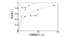
- X A is filled showing reduction ratio of P 4 O 10 at each position of the layer (the molar ratio).
- ⁇ A means the rate of increase in volume due to the reaction, and is calculated from the initial volume Vol 0 and the volume F after the reaction is completed based on the following formula (10).
- FIG. 2 shows the relationship between the reduction rate X A of the P 4 O 10 gas and the packed bed length for each of the cases where the volume increase rate ⁇ A is 0 and 3.28.
- ⁇ A 0, indicated by a broken line passing through ⁇ in FIG. 2
- the packed bed length is doubled to 18 cm.
- the amount of carbon required to double the length of the packed bed, the heating energy of the packed bed, and the construction cost of the equipment are also about doubled.
- the phosphorus since the P 4 O 10 unreacted readily soluble in water a container holding the water (e.g., for use in the examples below, the flask container filled with water to recover the yellow phosphorus) in It can be recovered as an acid.
- the reduction ratio of phosphorus oxide (P 4 O 10) in the present invention in the case where the case where phosphorus oxide generated is reduced all phosphorus (g) 100%, production of phosphorus (g)
- the rate means the rate, and "conditions under which the reduction rate of phosphorylate is 70% or more” means the reduction rate from the start of formation of liquid phosphorus (L) to the end of addition of the phosphoric acid compound as a raw material. It means a condition in which the average is 70% or more.
- the production rate of phosphorus (g) can be calculated from the amounts of CO and H 2 assuming that P 4 O 10 produced from the supplied phosphoric acid compound is generated by the formulas (3), (7) and the like. ..
- Patent Document 3 phosphorus and polyphosphoric acid compounds are mixed and adhered to the quartz tube wall because the supply rate of phosphoric acid to the packed bed by heating of phosphoric acid is high, and the reaction with carbon (formula (5) and a large amount of CO and H 2 is generated by the reaction) of the formula (6), mainly due to P 4 O 10 gas unreacted his stay in the carbon material filling layer is large amount discharged out of the layer Is considered to be. Therefore, when the reduction reaction is carried out in the carbon material packed bed using phosphoric acid as a raw material, the reactions of the formulas (5) and (6) can be allowed to proceed as much as possible within the range in which the polyphosphoric acid compound is not formed in the packed bed. It becomes important.
- the carbon material used as the reducing material for phosphor oxide is not particularly limited, but is preferably a carbon material having a large specific surface area, such as activated carbon, coke, carbon black, graphite, carbon fiber, and carbon nanotube (CNT). , VGCF TM, fullerene, charcoal and the like are used.
- Phosphorus has long been known as an allotrope such as white phosphorus (yellow phosphorus), red phosphorus, purple phosphorus, black phosphorus, and red phosphorus. Although yellow phosphorus was considered to be an allotrope, it is actually crude white phosphorus containing impurities (red phosphorus, etc.) and is not considered to be an allotrope.
- White phosphorus (P4) is a tetrahedral molecule, and is a white waxy solid at normal temperature and pressure with a specific gravity of 1.82, a melting point of 44 ° C., and a boiling point of 280 ° C. It changes to red phosphorus when exposed to sunlight.
- Red phosphorus is a mixture with white phosphorus containing purple phosphorus as a main component, and is a reddish brown powder having a specific gravity of 2.20 to 2.34, a melting point of 590 ° C., and an ignition point of 260 ° C.
- Purple phosphorus is a solid with a specific density of 2.36, and has a dark purple color with a brown tinge and a metallic luster.
- Black phosphorus is a solid with a specific density of 2.69 and is the most stable of allotropes.
- the phosphorus obtained by the production method of the present invention is not limited to a specific allotrope, and the term "phosphorus" is used in the present invention to include all of these allotropes.
- white phosphorus has a boiling point of 280 ° C. and a melting point of 44 ° C., and if the generated high-temperature phosphorus (g) is cooled in the range of less than 280 ° C. to 44 ° C. or higher, phosphorus should condense as a liquid.
- phosphorus (L) is not produced even though a temperature region below the boiling point of phosphorus exists. Further, phosphorus is said to have a remarkable supercooling phenomenon even at a melting point of 44 ° C. or lower, and may show a liquid state even at room temperature of 44 ° C. or lower.
- the carbon material-filled layer is sufficiently long even if the amount of gas in the carbon material-filled layer increases due to the progress of the reactions of the above formulas (5) and / or the formula (6), P introduced into the carbon material-filled layer.
- the reaction of the 4 O 10 gas with carbon can be sufficiently allowed to proceed in the carbon material packed bed.
- the length of the carbon material-filled layer cannot exceed a predetermined length due to cost and location restrictions. Therefore, it is necessary to know the amount of reaction at which the reduction reaction is completed with the limited length of the carbon material packed bed.
- Reduction reaction is complete in a carbon material filled layer, use more exhaust gas when all the generated phosphorous was assumed and collected as liquids, CO and H 2 generated in the reduction, and the transport of P 4 O 10 gas It consists only of non-oxidizing gas such as Ar gas. Therefore, the reaction amount in the entire carbon material-filled layer at a predetermined time can be evaluated by measuring the flow rate of the gas discharged from the reaction tube (column) in the flow-type reaction.
- P 4 O 10 is a compound having a melting point of 340 ° C. and a sublimation point of 360 ° C., and has high reactivity with water. If the reaction of the above formula (5) is not promoted, the reverse reaction of the above formula (4) will occur. It ends up.
- the exhaust gas can be used as a material or fuel after the separation operation, or can be reused as a non-oxidizing gas in the production method of the present invention.
- the reaction of a carbon material filled layer is determined by the feed rate of P 4 O 10 gas into the carbon material filled layer.
- P 4 O 10 gas supply amount the conveying gas is introduced into the phosphate compound heated region (non-oxidizing gas, e.g., rare gas or nitrogen gas such as Ar) when the flow rate of the constant, phosphoric acid compound heated region Depends on the temperature of.
- phosphate compound heated region non-oxidizing gas, e.g., rare gas or nitrogen gas such as Ar
- predetermined characteristics length, particle size of the carbon material particles, such as the reaction tube diameter
- it measures the flow rate of the gas discharged from the reaction tube corresponding, P 4 O 10 of unreacted by obtaining the temperature of the phosphoric acid compound heated region not precipitated in the reaction tube wall was set to a predetermined length
- the temperature of the phosphoric acid compound heating region where the reduction of P 4 O 10 gas proceeds at a specific reduction rate in the packed bed, in other words, the P 4 O 10 gas supply rate can be determined. Incidentally, precipitation of the reaction wall of the P 4 O 10 can be easily confirmed by its color.
- the total amount of gas generated by the reaction (referred to as the total exhaust gas flow rate in the present invention) can be easily measured. Therefore, based on the measurement of the total flow rate of the exhaust gas, knowing the supply temperature of P 4 O 10 to P 4 O 10 is not deposited in the reaction tube wall at the carbon material filled layer having a predetermined property, the temperature of the phosphoric acid compound heated region the set to be below that temperature by controlling the reduction reaction of P 4 O 10 can proceed in a particular reduction ratio at the carbon material filled layer.
- the amount of gas generated is measured using a flow meter, and the total exhaust gas flow rate (total exhaust gas) is determined by any of the following so that the increase in the amount of gas generated does not exceed the permissible range.
- the amount of generation can be controlled. That is, while measuring the amount of increase in gas generation, control and phosphorylation of the temperature at which the phosphoric acid compound as a raw material is heated to generate a phosphoric acid (also abbreviated as "heating temperature of the phosphoric acid compound" in the present invention).
- Controlling the temperature at which an object is brought into contact with a carbon material-filled layer to reduce it also abbreviated as "reduction reaction temperature of phosphorylate” in the present invention
- control of the amount of a phosphoric acid compound input as a raw material into a reaction tube can be controlled by at least one of them.
- the amount of gas generated can also be adjusted by adjusting the flow rate of the non-oxidizing gas.
- the gas flow rate in the carbon material packed bed is controlled to be equal to or less than a predetermined value, and phosphorus as a raw material is used. It is possible to control the reduction of P 4 O 10 generated from an acid compound to phosphorus (g) by improving the reduction rate in the reduction reaction layer (carbon material-filled layer) to a range equal to or higher than a specific reduction rate. preferable.
- the reduction rate of the phosphoric acid compound becomes 70% or more by adjusting (controlling) at least one of the heating temperature of the phosphoric acid compound and the non-oxidizing gas flow rate. Therefore, it is preferable to carry out a reduction reaction of phosphoric acid in the carbon material packed bed.
- a carbon material is further placed in the subsequent stage (downstream side) of the carbon material-filled layer for the reduction reaction. It is preferable to extend the packed bed.
- the portion of the extended carbon material filling layer (the portion having a temperature of less than 280 ° C.) becomes the condensation promoting member filling layer, and as will be described later, the temperature of the outlet side (downstream side) end is 44 ° C. or higher or phosphorus ( It is preferable to set g) to be substantially equal to or higher than the lower limit temperature for condensation, more preferably to be set to 44 ° C.
- the collision frequency of phosphorus (g) with the surface of the carbon material constituting the packing layer and the collision frequency between phosphorus (g) can be determined. It can be increased and promotes nucleation and growth of liquid phosphorus (L). As a result, the liquid phosphorus (g) can be effectively condensed on the surface of the condensation promoting member and the wall of the reaction tube having the condensation promoting member filling layer.
- the liquid phosphorus (L) can be recovered more efficiently by flowing it downstream, for example, by aggregating it in a container containing water installed in the lower part of the reaction tube. Can be done.
- the material used as the condensation promoting member is not particularly limited as long as it is a material capable of transferring heat of condensation that condenses phosphorus vapor to phosphorus (liquid) without reacting with phosphorus vapor (phosphorus (g)). be able to.
- activated carbon, coke, carbon black, graphite, carbon fiber, carbon nanotubes (CNT) such as VGCF (trade name, manufactured by Showa Denko), carbon materials such as fullerene, charcoal, glassy carbon, glass, quartz, silica gel, silica.
- Inorganic materials such as alumina, alumina, molecular sieves, clay, diatoms, and pebble, porous beads of styrene / divinylbenzene copolymer, polymer materials such as Teflon (registered trademark, manufactured by DuPont), and various metal materials can be used. ..
- the shape and size of the condensation promoting member are not particularly limited, but a porous granular material or a plate-like material is preferably used.
- the condensation-promoting member-filled layer should have a ventilation structure in which phosphorus (g) is condensed in the layer and the generated gas does not accumulate in the condensation-promoting member-filled layer and can escape downstream in the reaction tube. It is not particularly limited, and a layer filled with the above-mentioned aggregation promoting member can be used.
- the volume occupied by the condensation-promoting member packing layer per mass (gram) of the raw material phosphoric acid compound depends on the specific gravity, surface area, specific surface area, etc. of the condensation-promoting member.
- the volume is preferably 0.01 to 100 cm 3 / gram, more preferably 0.1 to 50 cm 3 / gram, from the viewpoint of the condensing effect and cost.
- a phosphor oxide produced by heating a liquid phosphoric acid compound is reduced by contacting it with a carbon material to produce gaseous phosphorus (g).
- the reaction of condensing the gaseous phosphorus (g) to obtain the liquid phosphorus (L) is carried out by a flow-type reaction under the non-oxidizing gas flow.
- the reduction reaction of the phosphor oxide is carried out in the carbon material packed layer, and the condensed gaseous phosphorus (g) generated is placed in contact with the carbon material packed layer and downstream of the carbon material packed layer. It is substantially carried out in the packed layer of the condensation promoting member.
- the manufacturing method of phosphorus of the present invention the flow reaction under non-oxidizing gas flow, the occurrence of (1) phosphorus oxides by heating phosphoric acid compound (mainly P 4 O 10), (2) generating From the three elements of reduction of the phosphor oxide produced by the carbon material (carbon material packed layer) and (3) formation of liquid phosphorus (L) by condensation of the produced phosphorus (g) in the aggregation promoting member packed layer. It is configured.
- Phosphoric acid compounds used in the method for producing phosphorus of the present invention include not only general phosphoric acid (H 3 PO 4 ), phosphorous acid (H 3 PO 3 ) and metaphosphoric acid (HPO 3 ), but also H.
- Condensed phosphoric acid represented by the demonstrative formula of n + 2 P n O 3n + 1 (1 ⁇ n ⁇ 3) can also be used. When n is 4 or more, the viscosity of condensed phosphoric acid becomes large and it becomes difficult to supply it, which is not preferable.
- n 1 orthophosphoric acid (H 3 PO 4 ), which is generally marketed as "phosphoric acid”, is a hydrous phosphoric acid containing about 15% by mass of water.
- n 1 orthophosphoric acid containing almost no water (moisture content of 0.1% by mass or less) is orthophosphoric acid, and phosphoric acid having a water content of more than 0.1% by mass is phosphoric acid. Called.
- the amount of water in the condensed phosphoric acid produced by dehydration of phosphoric acid is small.
- the decrease in water content in condensed phosphoric acid may increase the viscosity, making it difficult to handle.
- the viscosity of pyrophosphoric acid is not much different from that of orthophosphoric acid (H 3 PO 4). Therefore, as the condensed phosphoric acid used as a feed material, orthophosphoric acid or pyrophosphoric acid (diphosphoric acid) is practically preferable.
- crude condensed phosphoric acid can also be used as the phosphoric acid compound.
- the crude condensed phosphoric acid means a mixture of condensed phosphoric acids having 1 ⁇ n ⁇ 4 among the condensed phosphoric acids represented by the differential formula H n + 2 P n O 3 n + 1.
- the phosphoric acid compound used in the present invention may contain impurities other than the phosphoric acid compound and water.
- impurities other than the phosphoric acid compound and water.
- crude phosphoric acid and / or crude phosphorous acid obtained by leaching with acid from steelmaking slag obtained from the steel industry can be used.
- compositions of the leachates A, B and C are as shown in Table 1 below (unit: mg / L).
- at least one of crude phosphoric acid, crude condensed phosphoric acid and crude phosphoric acid can be used as the phosphoric acid compound, so that phosphorus contained in steelmaking slag, sewage sludge, etc. Phosphorus can be produced from resources, waste containing phosphorus.
- ash and the like contained in crude phosphoric acid and / or crude phosphorous acid may be removed by a conventional method before being used as a raw material, and in the production method of the present invention, a step of removing in an intermediate step is provided. May be good. However, it is desirable to remove those that generate low melting point oxides before using them as raw materials.
- the non-oxidizing gas circulated in the reaction system in order to create a non-oxidizing gas atmosphere includes hydrogen gas, carbon monoxide gas, and hydrocarbon gas (CH 4 , C 3 H 8 , C). 4, etc. H 10) a reducing gas, such as, and argon gas, an inert gas such as helium gas and the like. Among these, an inert gas is preferable in consideration of safety.
- Production of phosphorus from phosphate (H 3 PO 4) (P 4) is a historically Scheele and Gahn in 1770, the mixture mixed phosphoric acid and charcoal made by heating a crucible ..
- the crucible heating method was used until the advent of the electric furnace method in 1888.
- the crucible heating method is a batch method in which yellow phosphorus produced by heating a crucible filled with raw materials is deposited on the upper wall of the crucible in a low temperature part, the crucible is cooled to room temperature, the precipitated yellow phosphorus is collected, and then replaced with a new crucible. Met. Therefore, the production efficiency is very low, and it has been replaced by the electric furnace method, which has high productivity due to continuous operation.
- the phosphoric acid compound is continuously or discontinuously placed in a high temperature portion while preventing abrupt volume expansion due to instantaneous vaporization of the phosphoric acid compound. It is also possible to quantitatively and stably produce yellow phosphorus.
- "supplying the phosphoric acid compound continuously or discontinuously” means supplying the phosphoric acid compound so that the target liquid phosphorus is quantitatively and stably produced without interruption. It may be in the form of doing.
- a discontinuous supply form there is a form in which the supply is intermittently performed at regular intervals, and as will be described later, droplets are dropped at regular time intervals or impregnated with a phosphoric acid compound. Examples thereof include a form in which a carbon material is supplied at regular time intervals.
- the rate of formation of P 4 O 10 gas largely depends on the supply method of the carbon material filled layer of phosphate compound.
- phosphate ore as a raw material, carbon and silica as a reducing agent are charged from the upper part of the electric furnace at predetermined intervals to reduce carbon, and the generated phosphorus vapor is guided to a scrubber from the upper part of the electric furnace and recovered. doing.
- the raw materials to be charged are all solid, and when they are supplied to a high-temperature electric furnace, the temperature of the raw materials to be charged gradually rises and melts and accumulates in the lower part of the furnace, so that reduction starts.
- the liquid phosphoric acid compound is supplied to the high temperature part.
- the phosphoric acid compound is a liquid containing water, and if it is directly supplied to the upper part of the carbon material packed bed at around 1000 ° C., there is a risk of steam explosion due to evaporation of water, which makes it difficult to continue the reaction. Therefore, a supply method that avoids such a rapid volume expansion is required.
- the heating of the phosphoric acid compound generates water vapor and P 4 O 10 , and the phosphoric acid compound itself is dehydrated and condensed to form a polymer (condensed phosphoric acid) represented by H n + 2 P n O 3 n + 1.
- a polymer condensed phosphoric acid
- H n + 2 P n O 3 n + 1 As the temperature rises, phosphoric acid polymers having various degrees of polymerization are formed, and as the condensation progresses, the apparent P 4 O 10 concentration increases, and the generation rate of P 4 O 10 gas changes according to the composition.
- a heating experiment temperature rise rate of 10 ° C./min
- H 3 PO 4 phosphoric acid
- the horizontal axis represents the heating temperature (unit: ° C.), and the vertical axis represents the weight change rate (unit:%) of the sample (phosphoric acid).
- (1) it exists in a state of approximately 85% H 3 PO 4 at 100 ° C., and then becomes orthophosphoric acid at (2) about 250 ° C. due to evaporation of water with increasing temperature.
- the composition of pyrophosphoric acid (diphosphoric acid) becomes.
- the weight loss rate decreases
- the condensation reaction rate decreases
- the weight rapidly decreases after reaching about 770 ° C. This corresponds to begin to vaporize P 4 O 10 directly.
- the water contained in the various phosphoric acid compounds used as the raw material becomes steam after heating, reacts with carbon by the reaction represented by the above formula (5), and consumes carbon. Therefore, it is desirable to reduce the water content in various phosphoric acid compounds as raw materials as much as possible.
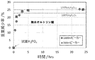
- FIG. 4 shows the results of vacuum dehydration of hydrous phosphoric acid (moisture content: 15% by mass) at 200 ° C.
- the broken line in the figure shows the value at which hydrous phosphoric acid is dehydrated to become anhydrous orthophosphoric acid.
- the composition becomes almost the composition of pyrophosphoric acid (H 4 P 2 O 7) after treatment for about 4 hours. After 24 hours, the composition is apparently close to that of tripolyphosphoric acid (H 5 P 3 O 10).
- hydrous phosphoric acid is vacuum dehydrated at 200 ° C. to reduce the water content to make orthophosphoric anhydride or pyrophosphoric acid (H 4 P 2 O 7 ), and these are impregnated with activated carbon and supplied.
- orthophosphoric anhydride or pyrophosphoric acid H 4 P 2 O 7
- these droplets are continuously and stably supplied by dropping and supplying these droplets at predetermined time intervals without impregnating the activated carbon. It was also found that it is possible to carry out a reduction reaction.
- a container in which a predetermined amount of the phosphoric acid compound is held on the gas inlet side of the packing layer to be subjected to the reduction reaction.
- a phosphoric acid compound for example, activated charcoal containing a phosphoric acid compound
- the phosphoric acid compound may be replenished to the phosphoric acid compound heating region continuously without interruption, or may be performed intermittently at predetermined time intervals.
- the temperature for heating the phosphoric acid compound is preferably in the range of 200 to 1000 ° C. (200 ° C. or higher and 1000 ° C. or lower), and preferably in the range of 300 to 1000 ° C. (300 ° C. or higher and 1000 ° C. or lower). More preferred. As shown in FIG.
- the surface becomes a phosphoric acid oxide.
- the volume of the droplet of the phosphoric acid compound to be dropped, the temperature of the heating region of the dropped droplet (for example, the droplet heating region D of the phosphoric acid compound in FIG. 9), and the like are adjusted. Therefore, as described in FIG. 9, in the form in which the phosphoric acid compound is dropped and supplied as droplets, the “phosphoric acid compound heating region in which the liquid phosphoric acid compound is heated to generate phosphoric acid” is referred to as “the phosphoric acid compound heating region”.
- the “carbon material-filled layer region” that produces gaseous phosphorus (g) means a region of the carbon material-filled layer region E excluding the upstream surface on which the above-mentioned phosphoric acid is generated.
- the "condensation-promoting member-filled layer region C that condenses gaseous phosphorus (g) generated in the carbon material-filled layer region to generate liquid phosphorus (L)” means the condensation-promoting member-filled layer region C.
- the "heating temperature of the liquid phosphoric acid compound” means the temperature of the droplet heating region D of the phosphoric acid compound. From the above viewpoint, it is preferable that the liquid phosphoric acid compound is dropped in the form of fine droplets having a volume of 15 ⁇ l or less.
- the lower limit of the volume of the fine droplets is not particularly limited, but is preferably 8 ⁇ l or more, for example.
- the case where the phosphoric acid compound is dropped as fine droplets can be achieved, for example, by using a nozzle having an inner diameter of 0.6 mm or less and having a tip cut at an angle of about 10 to 12 °.
- the material of the nozzle is not particularly limited, but stainless steel, Teflon (registered trademark, manufactured by DuPont) and the like can be used.
- the nozzle to be used can be appropriately adjusted in consideration of viscosity and the like according to the type of the phosphoric acid compound.
- the carbon material used in the carbon material filling layer used in the reduction reaction of P 4 O 10 may be any carbon material capable of reducing the phosphate compound is not particularly limited. Examples thereof include known graphite, amorphous carbon, charcoal, and activated carbon. Examples of amorphous carbon include carbon black, coal, coke, soot and the like. Further, as the form of the carbon material, for example, a powder, granular or porous carbon material molded product is used. However, when the powdered carbon material is filled in the packed layer as it is, the pressure in the layer may increase and the gas flow may be stagnant.
- the porous carriers impregnated with the phosphoric acid compound that can be used when supplying the phosphoric acid compound among the carbon materials described as the above-mentioned carbon materials as the porous carrier, the porous ones. Can be used. Further, a carbon material-filled layer formed of the above carbon material can also be used for a portion where the phosphoric acid compound is heated to generate phosphorylate.
- the carbon material-filled layer is formed by filling the reaction tube with the carbon material so that the generated gas does not accumulate in the carbon layer and can escape to the downstream of the reaction tube.
- the temperature of the reduction reaction packed bed region is preferably in the range of 700 ° C. to 1200 ° C. (700 ° C. or higher and 1200 ° C. or lower), and more preferably in the range of 900 to 1100 ° C. (900 ° C. or higher and 1100 ° C. or lower).
- the carbon material it is preferable to add the carbon material to the carbon material filling layer at predetermined time intervals according to the amount of decrease in the filling carbon material due to the reduction reaction of the phosphor oxide.
- the height of the carbon material-filled layer it is preferable to keep the height of the carbon material-filled layer substantially constant.
- Phosphorus has a boiling point of 280 ° C. and a melting point of 44 ° C., and the generated high-temperature phosphorus (g) usually condenses as phosphorus (L) when cooled in the range of less than 280 ° C. to 44 ° C. or higher. Therefore, in order to recover the phosphorus vapor generated by the reduction reaction as liquid phosphorus instead of gas, in the phosphorus production method of the present invention, the temperature is increased from the high temperature portion on the outlet side (downstream side) of the carbon material packing layer for the reduction reaction.
- a condensation promoting member filling layer formed from the above-mentioned condensation promoting member is provided in the region where the temperature gradually decreases.
- phosphorus vapor is passed through a void (space) in which particles of the condensation-promoting member are not filled, and the frequency of collision between phosphorus vapor molecules or on the surface of the packed particle of phosphorus vapor molecules is increased. This promotes the condensation of the phosphorus vapor and causes the liquid phosphorus to flow down along the packed layer particle surface and the reaction tube wall. Since liquid phosphorus does not dissolve in water, a container containing water can be installed at the bottom of the reaction tube, and phosphorus can flow down and be recovered.
- the agglutination promoting member-filled layer has a structure capable of condensing phosphorus vapor and allowing the condensed liquid to flow down the reaction tube, and is configured by filling the reaction tube with the above-mentioned agglutination promoting member. .. However, a part of the condensed liquid phosphorus may stay in the condensation promoting member packing layer.
- the length of the condensation promoting member filling layer is designed so that the temperature at the outlet side (downstream side) end is 44 ° C. or higher, which is the melting point of phosphorus. It is preferable to do so.
- the temperature at the outlet side end is equal to or higher than the lower limit temperature at which phosphorus (g) is substantially condensed, that is, solid phosphorus is contained in the aggregation promoting member packing layer. It is also preferable to design the temperature so that the temperature is equal to or higher than the lower limit temperature at which liquid phosphorus can be obtained without precipitation.
- the temperature of the outlet side end portion it is more preferable to design the temperature of the outlet side end portion to be 100 ° C. or higher.
- the length of the condensation promoting member packing layer so that the temperature at the outlet side end is in a preferable range as described above, the aerial dispersed particles of the ultrafine solid phosphorus particles are made efficient while condensing the phosphorus vapor. It is also possible to prevent a phenomenon in which a system, a so-called aerosol, is conveyed through a gas stream in the condensation promoting member-filled layer. It is difficult to recover the solid phosphorus particles that have once become aerosols, and the phosphorus yield is significantly reduced.
- the condensation promoting member packing layer is affected not only by the temperature but also by the gas flow velocity in the packing layer, the shape of the packed particles, and the like.
- the condensation constant is theoretically obtained in the case of laminar flow, turbulent flow, etc. in a pipe having a simple shape such as a cylinder or a square, but the present invention is not limited thereto.
- the condensation promoting member filling layer the gaseous phosphorus (g) and the packed layer particles (condensation promoting member) are efficiently contacted, and the gaseous is in the minute space in the condensation promoting member filling layer.
- heat exchange between the gaseous phosphorus (g) and the particles in the condensation promoting member packing layer proceeds effectively.
- This also applies to generated gases other than phosphorus (g). Therefore, the gas temperature near the outlet and the temperature of the packed bed particles are almost equal. Therefore, an appropriate length of the condensation promoting member filling layer can be set by measuring and comparing the temperature on the downstream side of the set condensation promoting member filling layer and the discharged gas temperature. Many reports have been made on the estimation formulas of heat conduction in the packed bed, such as the Colburn formula, and it is also possible to estimate the length of the condensation promoting member packed bed using these.
- the production method of the present invention it is also preferable to provide a container holding water downstream of the condensation promoting member filling layer.
- the above-mentioned container holding water recovers the liquid phosphorus (L) condensed in the aggregation promoting member filling layer, and is discharged by a reduction rate adjusted by the length of the carbon material filling layer, etc., unreacted.
- Phosphoryl oxide can be recovered as phosphoric acid.
- the method for producing phosphorus of the present invention can be carried out by the following production apparatus.
- a phosphorus production device that obtains liquid phosphorus (L) by a flow-type reaction under non-oxidizing gas flow using a liquid phosphoric acid compound as a starting material. From upstream to downstream, a phosphoric acid compound heating region that produces phosphoric acid produced by heating a liquid phosphoric acid compound and a gaseous phosphorus (gaseous phosphorus) by reducing the phosphoric acid generated in the phosphoric acid compound heating region.
- Each of the above regions in the manufacturing apparatus is usually housed in one reaction tube.
- this production apparatus is in a form in which a liquid phosphoric acid compound is continuously or discontinuously supplied to the phosphoric acid compound heating region, so that continuous production of phosphorus can be achieved. It is preferably in a possible form. Further, it is preferable that the gaseous phosphorus (g) is substantially condensed in the condensation promoting member-filled layer region, and such a form is also as described in the above description of the phosphorus production method. For example, by controlling the gas flow rate generated in the reduction reaction or controlling the flow rate of the non-oxidizing gas, the gas flow rate can be controlled to control the gaseous phosphorus (g) in the condensation promoting member packed bed region. It becomes possible to substantially perform the condensation.
- the reduction reaction of the phosphor oxide gas in the carbon material packed bed region it is more preferable to proceed the reduction reaction of the phosphor oxide gas in the carbon material packed bed region at a specific reduction rate as described above. It is also preferable to have a configuration in which the input of the phosphoric acid compound can be controlled so that the flow rate of the generated gas falls within a certain control range, and every predetermined time according to the amount of decrease in the carbon material in the carbon material packed bed. It is also preferable to provide a structure capable of supplying the carbon material to the carbon material filling layer.
- the above-mentioned production apparatus is at least one of the dropping of the phosphoric acid compound or the supply of the phosphoric acid compound-impregnated porous carrier, the heating control of the supplied phosphoric acid compound, the amount of gas generated by the reduction reaction, and the recovery amount of liquid phosphorus. It is preferable to include a control unit that automatically controls one of them.
- the temperature control of each region in the manufacturing apparatus is as described in the phosphorus manufacturing method described above.
- phosphorus (g) is condensed to obtain liquid phosphorus (L), so that the temperature range of 44 ° C. or higher and lower than 280 ° C. or phosphorus (g) is substantially set. It is preferable to cool in the temperature range where it condenses.
- the temperature range in which phosphorus (g) is substantially condensed is the temperature at which liquid phosphorus can be obtained without precipitating solid phosphorus in the aggregation promoting member packed bed when phosphorus is in a supercooled state. Means a range.
- the cooling means, cooling rate, and the like are not particularly limited as long as phosphorus (g) can be condensed to obtain liquid phosphorus (L), and a normal cooling method can be appropriately adopted.
- it can be cooled by using at least one of gas (for example, air cooling with air), liquid (for example, water cooling with water) and solid, or a combination thereof.
- the cooling rate is not particularly limited.
- the efficiency of condensing gaseous phosphorus (g) into liquid phosphorus (L) can be further increased.
- room temperature means 25 ° C.
- g of "phosphorus (g)” means gas, and other "g” means gram.
- the yield means the ratio of actually obtained yellow phosphorus to total phosphorus in the phosphoric acid compound as a raw material, which is estimated from the mass balance before and after the reaction.
- Example 1 Phosphoric acid reduction by a horizontal activated carbon packed bed reactor The phosphoric acid was reduced by carbon using a horizontal electric furnace.
- the outline of the apparatus used in the experiment is shown in FIG.
- a quartz reaction tube 1 (inner diameter 22 mm, length 120 cm) was installed in a horizontal electric furnace (only heating regions H 1 and H 2 are shown) at an angle of about 5 degrees from the gas inlet 2 toward the outlet 3 directions. Due to the inclination of the quartz reaction tube 1, the generated liquid phosphorus L can be stored in the downstream end of the quartz reaction tube 1 as shown in FIG.
- Both ends of the quartz reaction tube 1 are closed with rubber stoppers 4 (4a, 4b), a glass tube 5 is inserted into each of these rubber stoppers, and argon gas is introduced from the glass tube 5 inserted through the rubber stopper 4a to the quartz reaction tube 1 At the same time, the gas generated by the reaction is discharged from the glass tube 5 inserted through the rubber stopper 4b.
- Horizontal electric furnace two heating areas, i.e., composed of H 1 region (15cm) and H 2 region (30 cm).
- H 1 region corresponds to phosphoric acid compound heating region A.
- H 2 region by reducing phosphorus oxide generated in the phosphoric acid compound heating area A, corresponding to the carbon material filling layer region B to generate a gaseous phosphorus (g).
- the temperatures of the heating regions H 1 and H 2 can be controlled independently.
- Activated carbon (manufactured by Wako Pure Chemical Industries, Ltd.) is filled in a length of about 45 cm as a carbon material packed layer region B in the quartz reaction tube 1 and a condensation promoting member packed layer region C located downstream of this region B. did.
- Phosphoric acid compound heating region A in front of region B (upstream side) was filled with phosphoric acid-containing (impregnated) activated carbon in which 10 g of phosphoric acid having a water content of 15% by mass was impregnated in 10 g of activated carbon to a length of about 15 cm ( Total amount of phosphoric acid 10g).
- Carbon material filling layer region B of the quartz reaction tube 1 in the heating region of H 2 horizontal furnace was installed so that the corresponding phosphate Compound heating area A in the heating region H 1 of the horizontal furnace.
- a coagulation promoting member packed layer region having a length of 15 cm without temperature control is performed on the downstream side of the carbon material packed layer region B (about 30 cm) of the quartz reaction tube 1, that is, on the downstream side of the horizontal electric furnace.
- C was installed on the downstream side of the carbon material packed layer region B (about 30 cm) of the quartz reaction tube 1, that is, on the downstream side of the horizontal electric furnace.
- C was installed on the downstream side of the carbon material packed layer region B (about 30 cm) of the quartz reaction tube 1, that is, on the downstream side of the horizontal electric furnace.
- C was installed on the downstream side of the carbon material packed layer region B (about 30 cm) of the quartz reaction tube 1, that is, on the downstream side of the horizontal electric furnace.
- C was installed on the downstream side of the carbon material packed layer region B (about 30 cm)
- the gaseous phosphorus (g) is substantially condensed in the condensation promoting member packing layer region C, but a very small amount of the gaseous phosphorus (g) is the condensation promoting member filling layer.
- Some are discharged from the quartz reaction tube 1 without condensing in the region C.
- This unrecovered phosphorus is an extremely small amount that does not substantially affect the phosphorus recovery rate, and is about 1/1000 of the phosphorus recovery rate.
- the discharged phosphorus (g) is recovered by connecting a flask in which the glass tube 5 on the gas outlet 3 side of the quartz reaction tube is filled with ion-exchanged water 7 and bubbling the exhaust gas into water.
- a flask filled with bromine water 8 is connected to bubbling the exhaust gas to completely remove yellow phosphorus.
- the mouth of the flask filled with ion-exchanged water 7 is a rubber stopper 4c
- the mouth of the flask filled with bromine water 8 is a rubber stopper 4d
- gas is passed through the glass tube 5 inserted through these rubber stoppers. It was distributed.
- the exhaust gas after removing yellow phosphorus is dehydrated through a dehydration pipe (not shown) filled with silica gel, and then the amount of generated gas is measured every minute with a gas flow meter (not shown).
- argon (Ar) was flowed into the quartz reaction tube 1 from the gas inlet 2 at a flow rate of 20 cm 3 / min, and the air in the system was completely replaced with Ar. Then, while flowing Ar at the same gas supply rate, the temperature of the carbon material-filled layer region B filled with activated carbon was raised to 1000 ° C. After that, Ar was continuously flowed at the same flow rate during the experiment. After holding the carbon material packed layer region B at 1000 ° C. for 10 minutes, the temperature of the phosphoric acid compound heating region A filled with 20 g of phosphoric acid-containing activated carbon (total phosphoric acid amount is 10 g) was set to 300 ° C. at a rate of 20 ° C./min.
- the resulting liquid was identified as yellow phosphorus.
- the results of Raman spectroscopy are shown in FIG. Since the amount of generated gas was not measured in Example 1, the yield was calculated from the recovered yellow phosphorus. It is known that yellow phosphorus remains in the carbon-filled layer in the production apparatus after the reaction, and it is estimated that the yield will be 70% or more when these are added.
- Example 2 Phosphoric acid reduction by a vertical activated carbon packed bed reactor
- the phosphoric acid was reduced by carbon using a vertical electric furnace.
- FIG. 7 shows an outline of the apparatus used in the experiment.
- the vertical electric furnace consists of two heating regions H 1 and H 2 having a length of 30 cm, each of which can control the temperature independently.
- Each heating region as shown in FIG. 7 reduction, quartz reaction tube 1 (inner diameter 32 mm, length 1200 mm) phosphate compound heating region A in, and the carbon material of the phosphorus oxide such as P 4 O 10 that occurred Corresponds to the carbon material packed layer region B.
- the upper end of the quartz reaction tube 1 is closed by a rubber stopper 4a through which the glass tube 5 is inserted, and argon gas is introduced into the quartz reaction tube 1 from the glass tube 5.
- a quartz tube 6 having an outer diameter of 8 mm is connected to the lower end of the quartz reaction tube 1 installed in the vertical electric furnace.
- Activated carbon was filled in the carbon material packed layer region B of the quartz reaction tube 1 and the condensation promoting member packed layer region C located on the downstream side of this region B to a length of about 40 cm.
- upper 30cm corresponds to the heating region H 2
- lower 10cm does not perform temperature control, are placed to exit to the outside of the heating region H 2.
- Phosphoric acid-containing (impregnated) activated carbon in which 10 g of phosphoric acid having a water content of 15% by mass is impregnated in 10 g of activated carbon is placed in the phosphoric acid compound heating region A above the packed layer of the carbon material packed layer region B where the reduction reaction is performed. It was filled to a length of 15 cm.
- a blank is displayed between the phosphoric acid compound heating region A and the carbon material packed bed region B for the sake of visibility, and in reality, the two regions A and the two regions A are displayed. It exists so as to be in contact with B.
- the temperature at the boundary between the region C and the region B is about 300 ° C.
- the temperature near the outlet side (downstream side) of the region C is about 120 ° C. Met.
- the quartz tube 6 at the lower end of the quartz reaction tube 1 inserted through the rubber stopper 4b was introduced into a flask filled with water 7.
- phosphorus element-containing exhaust gas (P 4 O 10 etc.) that could not be recovered as liquid phosphorus was bubbling in water 7 and cooled, so that P 4 O 10 that was not reduced was used as phosphoric acid. to recover.
- phosphorus is completely removed by bubbling the exhaust gas from the flask filled with water 7 to the bromine water 8 through the glass tube 5 inserted through the rubber stopper 4c.
- the exhaust gas after removing phosphorus is dehydrated through a dehydration pipe 9 filled with silica gel, and then the flow rate of gas (CO and hydrogen) generated by the gas flow meter 10 is measured every minute.
- the temperature of the phosphoric acid compound heating region A was gradually increased within the range where the amount of generated gas was 200 cc or less per minute, and the temperature was raised to 700 ° C. From the time when the temperature of the region A reached 300 ° C., a gas with a flow rate slightly higher than the introduced Ar gas flow rate (20 cm 3 / min) was generated, and the amount of generated gas increased as the temperature of the phosphoric acid compound heating region A increased. .. When the temperature of the phosphoric acid compound heating region A reaches about 500 ° C., droplets are observed to adhere to the lower wall surface of the quartz reaction tube 1, and these are the wall surfaces of the quartz reaction tube 1 and the quartz tube 6.
- Example 3 Continuous supply of phosphoric acid-containing activated carbon Phosphoric acid reduction by a vertical carbon material packed bed reactor
- the equipment and method used in this example are basically the same as in Example 2 except for the points described below. Is.
- phosphoric acid as a raw material
- a predetermined amount of phosphoric acid-containing (impregnated) activated carbon phosphoric acid having a water content of about 15% by mass is used, and the average weight ratio of phosphoric acid to activated carbon (phosphoric acid / carbon) is about. (Adjusted to 2.6) was dropped onto the upper part of the carbon material-filled layer at predetermined time intervals.
- FIG. 8 shows an outline of the reaction system.
- a quartz reaction tube 1 (inner diameter 32 mm, length 1200 mm) having a quartz tube 6 having an outer diameter of 8 mm is installed in a vertical electric furnace at the lower end.
- a container 12 (the phosphoric acid-containing activated carbon in the container is not shown) holding the phosphoric acid-containing activated carbon via two valves 11 (11a, 11b) is provided on the upper part of the quartz reaction tube 1. It is connected. First, the upper valve 11a is opened, activated carbon containing a predetermined amount of phosphoric acid is dropped into the space area 13 on the lower valve 11b, and the upper valve 11a is closed.
- the vertical electric furnace is composed of two heating regions H 1 and H 2 having a length of 30 cm, each of which can control the temperature independently.
- Each heating region as shown in FIG. 8, quartz reaction tube 1 of phosphate oxide phosphoric acid to generate compound heating region A, and phosphorus oxides such as P 4 O 10 that occurred was reduced by a carbon material Corresponds to the carbon material packed bed region B that produces gaseous phosphorus (g).
- the phosphoric acid-containing activated carbon material-filled layer did not exist in the phosphoric acid compound heating region A of the quartz reaction tube 1 before the start of the experiment.
- the carbon material packed layer region B and the condensation promoting member packed layer region C of the quartz reaction tube 1 were filled with activated carbon to a length of about 40 cm.
- the upper 30 cm of the packed bed is arranged outside the electric furnace so that the upper 30 cm is contained in the carbon material packed bed area B of the electric furnace, and the lower 10 cm is arranged outside the electric furnace and corresponds to the area where the temperature is not controlled (corresponding to the condensation promoting member packed bed area C). It was filled so as to be an area).
- the phosphorus recovery and exhaust gas treatment system is the same as in Example 2.
- the temperature at the boundary between the region C and the region B is about 300 ° C.
- the temperature near the outlet side (downstream side) of the region C is 120 ° C. there were.
- the total exhaust gas flow rate increased after the third injection, reaching about 150 cm 3 / min. After that, while observing a flow meter (not shown), when the amount of generated gas decreased to 100 cm 3 / min or less, about 1 g of new phosphoric acid-containing activated carbon was added. After that, this operation was repeated (total phosphoric acid amount 50 g). Thirty minutes after the start of charging the phosphoric acid-containing activated carbon, droplets adhered to the wall surface under the quartz reaction tube 1, coalesced, and the droplets flowed down and aggregated in the water 7 in the flask. 5 hours after the temperature rise start of the phosphoric acid compound heating region A and the experiment was terminated Turn off the H 1 and H 2. After the temperature of the electric furnace reaches room temperature, phosphorus (L) accumulated in the flask is recovered, its weight is measured (12.5 g, yield 71%), and it is analyzed by Raman spectroscopy to identify yellow phosphorus. did.
- the impurity element components of phosphorus obtained in Examples 1 to 3 and commercially available phosphorus were analyzed by ICP-AES emission spectroscopic analysis (apparatus; manufactured by Shimadzu Corporation, type: ICPS-8100 type), and Table 2 (The unit of the numerical value in Table 2 is ppm).
- Samples 1-3 correspond to the phosphorus obtained in Examples 1-3, respectively.
- the impurity element components of the obtained phosphorus were almost the same as those on the market.
- the production method of the present invention can stably and quantitatively produce high-purity phosphorus, which is almost the same as commercially available phosphorus, as liquid phosphorus (L). ..
- Example 4 Phosphate reduction in which dehydrated phosphoric acid droplets are dropped and supplied to a vertical carbon material-filled layer reactor
- the apparatus and method used in this example are basic except for the phosphoric acid supply method described below.
- a method was used in which a predetermined amount of the phosphoric acid compound (H 3 PO 4 ) was dropped as fine droplets from the upper part of the reaction tube onto the upper part of the carbon material packed layer at predetermined time intervals.
- FIG. 9 shows an outline of the reaction system. Vertical electric furnace comprising the heating region H 4 heating zones H 3 and the length 10cm length 90cm capable of controlling the respective temperatures independently. As shown in FIG.
- the lower end of the activated carbon packed bed 41 is arranged to exit the 10cm out from the lower part of the heating region H 4, it was placed a region that does not perform temperature control (region corresponding to the condensation accelerator member filling layer region C).
- region corresponding to the condensation accelerator member filling layer region C According to the temperature measurement of the reactor, in the reaction for obtaining phosphorus below, the temperature at the boundary between the region C and the region E is about 300 ° C., and the temperature near the outlet side (downstream side) of the region C is about 120 ° C. Met.
- phosphoric acid (H 3 PO 4 ) obtained by heating and dehydrating 85% phosphoric acid at 200 ° C. for 25 hours was used.
- a peristeric pump P was used to supply the dehydrated phosphoric acid (hereinafter, also simply referred to as phosphoric acid in Example 4) 31.
- a stainless steel pipe nozzle (with the tip cut to about 12 °) S with an inner diameter of 0.6 mm and a length of 26 mm is attached to the tip of the phosphoric acid transport silicon tube (inner diameter 2 mm x outer diameter 4 mm) used for the pump P.
- the distance from the upper part of the activated carbon-filled layer 41 to the tip of the stainless pipe nozzle S for dropping the droplet 33 is 300 cm.
- the dropping amount of the phosphoric acid droplet 33 was adjusted so that the feeding speed of the peristalic pump P was adjusted so that the supply amount per minute became a predetermined amount.
- the amount of gas generated by the reaction was continuously measured using a wet gas meter (gas flow meter 10).
- the droplet 33 was dropped over a reaction time of 60 minutes at a frequency of about 30 times per minute.
- the amount of droplets per droplet is about 0.013 g.
- the total input amount of the phosphoric acid compound 31 is 24.4 g.
- the microdroplets 33 of the phosphoric acid compound fall on the upper surface (upstream side surface) of the carbon material-filled layer region E and then become phosphorylates on the surface.
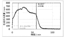
- the time change of the amount of gas generated from the start of the experiment is shown in FIG. Immediately after the start of dropping the phosphoric acid compound droplet 33, gas was generated.
- the height of the upper surface of the activated carbon-filled layer region E which is the region responsible for the reduction reaction, was lowered by about 5 cm.
- carbon which is a reducing agent, is continuously used for long-term continuous operation of the reducing reaction. It can be seen that it is necessary to add a predetermined amount targetly or intermittently.
- Example 5 Phosphoric acid reduction in which pyrophosphoric acid droplets are dropped and supplied to a vertical carbon material-filled layer reactor Examples of the apparatus and method used in this example, except that pyrophosphoric acid was supplied as a raw material phosphoric acid compound. It is exactly the same as 4.
- the phosphoric acid compound as a raw material is supplied by dropping a predetermined amount of pyrophosphoric acid (H 4 P 2 O 7 ) as fine droplets 33 from the upper part of the reaction tube onto the upper part of the activated carbon material packed bed region E at predetermined time intervals.
- pyrophosphoric acid obtained by heating and dehydrating 85% phosphoric acid at 200 ° C.
- the temperature at the boundary between the region C and the region E is about 300 ° C.
- the temperature near the outlet side (downstream side) of the region C is about 120 ° C. Met.
- the droplet 33 was dropped over a reaction time of 60 minutes at a frequency of about 25 times per minute.
- the total input amount of pyrophosphate 31 is 21 g.
- the microdroplets 33 of pyrophosphate fall on the upper surface (upstream side surface) of the carbon material-filled layer region E and then become phosphor oxides on the surface.
- the time change of gas generation from the start of the experiment is shown in FIG. Gas was generated immediately after the start of dropping the pyrophosphate droplet 33, and 10 minutes later, the total exhaust gas flow rate was the flow rate when the pyrophosphate added in 1 minute reacted 100%, and then an average of about 450 cm until 50 minutes later.
- Example 5 Compared with Example 4 in which droplets of phosphoric acid adjusted for dehydration were dropped, the recovery rate of phosphorus was lower in Example 5 using pyrophosphoric acid. This is because yellow phosphorus was also deposited on the side surface of the glass tube inserted in the flask, and this could not be recovered. It is considered that this is the reason why the yield was 57%. The yield is estimated to be 70% or more with the addition of yellow phosphorus remaining on the sides of the glass tube and in the carbon material packed bed. From these results, it can be seen that even when pyrophosphoric acid is used as a raw material, yellow phosphorus can be produced without any problem as in the case of dehydrated and adjusted phosphoric acid. As shown in Examples 4 and 5, it can be seen that high-purity phosphorus can be stably and quantitatively continuously produced as liquid phosphorus (L) by the production method of the present invention.
- L liquid phosphorus
- Example 6 Further, phosphorus was produced in the same manner as in Example 2 except that the leachates A to C shown in Table 1 described above were used instead of phosphoric acid having a water content of about 15% by mass as a raw material. As a result, it was confirmed that high-purity liquid phosphorus (L) can be stably and quantitatively obtained even when crude phosphoric acid containing a large amount of impurities is used as a raw material.
Landscapes
- Chemical & Material Sciences (AREA)
- Organic Chemistry (AREA)
- Inorganic Chemistry (AREA)
- Chemical Kinetics & Catalysis (AREA)
- Investigating Or Analyzing Non-Biological Materials By The Use Of Chemical Means (AREA)
- Devices And Processes Conducted In The Presence Of Fluids And Solid Particles (AREA)
- Catalysts (AREA)
- Inorganic Fibers (AREA)
Abstract
Description
例えば、米国特許第6207024号明細書(特許文献1)には、下記反応式(1)に従ってリン酸を炭素還元するリンの製造法が提案されている。
4H3PO4+16C→6H2+16CO+P4 (1)
本発明は、液状のリン酸化合物を出発原料として、高純度の液状のリン(L)を定量的に安定して製造する方法及び当該方法を実施するための装置を提供することを課題とする。
本発明はこれらの知見に基づき完成されるに至ったものである。
〔1〕
液状のリン酸化合物を加熱して生じるリン酸化物を炭素材と接触させることにより還元してガス状のリン(g)を生成し、このガス状のリン(g)を凝縮して液状のリン(L)を得る反応を、非酸化性ガス流通下の流通式反応により行うに当たり、前記のリン酸化物の還元反応を炭素材充填層内で行い、生成したガス状のリン(g)の凝縮を、前記炭素材充填層に接して前記炭素材充填層の下流に配した凝縮促進部材充填層内で実質的に行わせる、リンの製造方法。
〔2〕
前記の液状のリン酸化合物を連続的又は非連続的に供給することにより前記の液状のリン(L)を得る、〔1〕に記載のリンの製造方法。
〔3〕
前記の液状のリン酸化合物を多孔質担体に含浸させた状態で供給する、〔1〕又は〔2〕に記載のリンの製造方法。
〔4〕
前記の液状のリン酸化合物を滴下することにより供給する、〔1〕又は〔2〕に記載のリンの製造方法。
〔5〕
前記の液状のリン酸化合物を200~1000℃に加熱して前記のリン酸化物を生じ、前記のリン酸化物の還元反応温度を700~1200℃とする、〔1〕~〔4〕のいずれかに記載のリンの製造方法。
〔6〕
凝縮促進部材充填層における凝縮温度が44℃以上280℃未満の温度範囲又はリン(g)が実質的に凝縮する温度範囲である、請求項1~5のいずれか1項に記載のリンの製造方法。
〔7〕
前記の液状のリン酸化合物が、粗リン酸、粗縮合リン酸及び粗亜リン酸の少なくとも1種を含む、〔1〕~〔6〕のいずれかに記載のリンの製造方法。
〔8〕
前記の液状のリン酸化合物の加熱温度と、前記のリン酸化物の還元反応温度とを、それぞれ独立して制御する、〔1〕~〔7〕のいずれかに記載のリンの製造方法。
〔9〕
前記のリン酸化物の還元反応で発生する一酸化炭素ガスと水素ガスの総排出ガス流量に基づき、前記の液状のリン酸化合物の加熱温度及び非酸化性ガス流量の少なくともいずれかを制御することにより、前記炭素材充填層内で前記のリン酸化物の還元反応を行う、〔1〕~〔8〕のいずれかに記載のリンの製造方法。
〔10〕
前記のリン酸化物の還元反応において、未反応のリン酸化物を前記の凝縮促進部材充填層の下流に設置した水を保持した容器において回収する、〔1〕~〔9〕のいずれかに記載のリンの製造方法。
〔11〕
前記のリン酸化物の還元反応に伴う、前記炭素材充填層内の炭素材の減少量に応じて、所定の時間ごとに前記炭素材充填層に炭素材を供給する、〔1〕~〔10〕のいずれかに記載のリンの製造方法。
〔12〕
液状のリン酸化合物を出発原料として非酸化性ガス流通下の流通式反応により液状のリン(L)を得るリンの製造装置であって、
上流から下流に向けて、液状のリン酸化合物を加熱してリン酸化物を生じるリン酸化合物加熱領域と、該リン酸化合物加熱領域で生じたリン酸化物を還元してガス状のリン(g)を生成する炭素材充填層領域と、該炭素材充填層領域で生じたガス状のリン(g)を凝縮して液状のリン(L)を生じる凝縮促進部材充填層領域とをこの順に備えた、リンの製造装置。
〔13〕
前記の液状のリン酸化合物が前記リン酸化合物加熱領域へと連続的又は非連続的に供給される、〔12〕に記載のリンの製造装置。
〔14〕
前記凝縮促進部材充填層領域において前記のガス状のリン(g)の凝縮を実質的に行わせる、〔12〕又は〔13〕に記載のリンの製造装置。
〔15〕
さらに、前記炭素材充填層内の炭素材の減少量に応じて、所定の時間ごとに前記炭素材充填層に炭素材を供給する手段を備えた、〔12〕~〔14〕のいずれかに記載のリンの製造装置。
〔16〕
さらに、発生ガス流量が一定の制御範囲に入るように前記リン酸化合物の投入を制御できる手段を備えた、〔12〕~〔15〕のいずれかに記載のリンの製造装置。
〔17〕
前記リン酸化合物の、リン酸化合物の滴下又はリン酸化合物を含浸させた多孔質担体としての供給と、供給された前記リン酸化合物の加熱制御と、前記還元反応により発生するガス量と、前記の液状リンの回収量、の少なくとも一種を自動制御する制御部を備えた、〔12〕~〔16〕のいずれかに記載のリンの製造装置。
本発明において「上流」および「下流」との用語は、非酸化性ガスの流通方向に対して用いている。すなわち、非酸化性ガスが流入してくる側が上流であり、非酸化性ガスが流れ出ていく側が下流である。
本発明において「リン酸化物の還元反応を炭素材充填層内で行う」とは、液状のリン酸化合物を加熱して生じたリン酸化物を、炭素材充填層内で可能な限り還元することを意味する。後述する通り、原理的には充填層長さを長くするにつれて還元率は大きくなるものの、コストなどを考慮すると所定の長さ以上にすることは難しく、液状のリン酸化合物を加熱して生じたリン酸化物の70%以上が炭素材充填層内で還元されること、すなわち、リン酸化物の還元率が70%以上であることが好ましい。より好ましくは90%以上、さらに好ましくは95%以上、さらに好ましくは97%以上、さらに好ましくは99%以上が、炭素材充填層内で還元されることが望ましい。
本発明において「凝縮を」「凝縮促進部材充填層内で実質的に行わせる」とは、リン酸化物を炭素材充填層を構成する炭素材と接触させることにより還元して生じたガス状のリン(g)を実質的に、凝縮促進部材充填層内において凝縮させて液状とすることを意味する。前記「実質的に」とは、好ましくは、リン酸化物を炭素材と接触させることにより還元して生じたガス状のリン(g)の90質量%以上、より好ましくは95質量%以上、さらに好ましくは97質量%以上、さらに好ましくは99質量%以上が、凝縮促進部材充填層内において凝縮されることを言う。本発明の製造方法によれば、後述するように、リンの回収率には実質的に影響しない程度のガス状のリンが排出される程度とすることができる。
本発明のリンの製造装置は、本発明のリンの製造方法を実施するのに適した装置である。
本発明のリンの製造方法では、出発原料として液状のリン酸化合物が使用される。本発明において、「リン酸化合物」とは、後述する通りであり、オルトリン酸、オルトリン酸の脱水から生成する縮合リン酸、および亜リン酸等を包含する意味で用いる。
リン酸化合物を加熱して得られるリン酸化物は主にP4O10ガスからなり、POやPO2なども少量含まれる。本発明において、リン酸化物はリンの酸化物である限り、特定の示性式で表されるものに限定されない。以下の説明では、リン酸化物をその主成分であるP4O10のガスとして説明する。
なお、これまでリン酸化物は組成式P2O5で表されてきたが、実際の分子の構造は十酸化四リン(P4O10)であり、近年、高校の指導要領もこれを採用している。そのため、本発明においても、リン酸化物をP2O5ではなくP4O10として表記するが、両者は同義である。
またガス(気相)のリンはP4又はP2分子として存在するが、本発明では便宜上、P4として表し、生成する黄リンもP4と表した。
P4O10(L)+10C → P4(g)+10CO (2)
この反応では1モルのP4O10の還元により10モルのCOガスが発生する。しかし、反応は溶融しているリン酸化物を含むスラグと固体炭素間の反応であり、発生したCOガスがリン鉱石の溶融還元速度に直接影響を及ぼすことはない。
4H3PO4(L)+16C → P4(g)+16CO+6H2 (3)
4H3PO4(L) → 6H2O(g)+P4O10(g) (4)
H2O(g)+C → CO+H2 (5)
P4O10(g)+10C → P4(g)+10CO (6)
本発明の製造方法において、リン酸化合物として亜リン酸(H3PO3)、メタリン酸(HPO3)又は縮合リン酸を原料として用いた場合も、基本的にリン酸と同様の機構で反応が進行する。例えば、縮合リン酸であるピロリン酸(H4P2O7)を用いた場合、下記式(7)で示されるように、全体として2モルのH4P2O7の炭素材による還元により19モルのガスが発生する。
2H4P2O7+14C → P4(g)+14CO+4H2 (7)
以下、リン酸化合物としてリン酸を用いた場合を例に、リン酸化合物の炭素材による還元反応について詳述する。ただし、下記記載によりリン酸化合物がリン酸に限定されるものではなく、リン酸以外のリン酸化合物を用いた場合の還元反応についても、同様のことが言える。
黄リン生成反応を示す見かけの反応式である上記式(3)は実際には多くの反応が関与しているため、その正確な反応解析は容易ではない。しかし、本発明の炭素材充填層を用いたリン酸化物の還元による黄リンの製造を工業的に実装するためには、近似的にでも、現実的かつ簡便に炭素材充填層内でのP4O10ガスの還元反応を評価する方法を確立する必要がある。
上述の通り、リン酸化物の炭素材による還元反応においては、反応の進行に伴い反応系の体積は増加する。このことを考慮した還元反応を簡単に評価する反応モデルを以下に示す。
この反応モデルにおいて、リン酸化物の炭素材充填層における反応を流通式の反応とみなし、さらに充填層内の炭素材充填層を無視して充填層内の流れを栓流と仮定する。つまり充填層内の流れを、図1に示すように、無限に薄い円板dVのつながりとして管内を一定の速度で流れるとする。また、dV内でのP4O10ガスの濃度は一定と仮定する。近似的に還元反応をP4O10ガス濃度に比例する1次反応とすると、反応速度は下記式(8)で表される。
反応速度 = -k[P4O10ガス濃度] (8)
kは見かけの反応速度係数である。見かけの反応速度係数kは、実際には炭素材充填層の充填率、炭素材充填層を構成する炭素材粒子の粒径、炭素材粒子の表面積及び種類などに依存する。しかし、この反応モデルでは見かけの反応速度係数kをこれらの個々のパラメーターの影響をすべて含む反応を代表するパラメーターとして取り扱う。


上記式(8)を用いてkを決定できれば、各パラメーターが変化した場合に、還元率XAがどのように変化するかを計算することができる。また逆に、所定の還元率XAを得るために必要なパラメーターの値、例えば充填層の長さを計算することができる。
このことは、リン酸の還元において、例えば、充填層長さ10cmで還元率が75%(XA=0.75)となった場合、さらに還元率90%(XA=0.90)を達成するにするには、εA=0の場合は充填層長さを約3cm程度伸ばすだけで十分だが、εA=3.28の場合は充填層の長さを約2倍の18cmにする必要があることを意味する。実際の操業を考えた場合、充填層の長さを約2倍とするために必要な炭素量、充填層の加熱エネルギー及び装置の建設費用も、同じく2倍程度となる。
一方、未反応のP4O10は水に容易に溶けるため、水を保持した容器(例えば、後述の実施例において使用する、黄リンを回収するための水を満たしたフラスコ容器)中にリン酸として回収することができる。黄リン回収容器中に回収した場合には、黄リンと分離した後、本発明の製造方法に用いられる原料であるリン酸化合物として再利用することもできる。
よって、充填層長さを18cmとして還元率を90%とするか、充填層長さを10cmとして25%の未反応のP4O10をリン酸として回収するかは、全体のコストを総合的に考え、経済的な観点から決めることができる。
本発明の製造方法においては、還元率を70%以上(好ましくは80%以上、より好ましくは90%以上)とする条件によりリンを製造し、リン酸として回収したP4O10を再利用する方法が、より合理的であり好ましい。
なお、本発明においてリン酸化物(P4O10)の還元率とは、発生したリン酸化物が全てリン(g)に還元された場合を100%とした場合の、リン(g)の生成率を意味し、「リン酸化物の還元率が70%以上となる条件下」とは、液状のリン(L)の生成開始時から原料であるリン酸化合物の投入終了時までの還元率の平均が70%以上となる条件下を意味する。なおリン(g)の生成率は、供給されたリン酸化合物から生成したP4O10が式(3)、(7)等により発生すると仮定したCOとH2の量から算出することができる。すなわち、原料のリン酸化合物から計算される液状のリン(L)の収率が70%以上である場合には、上記のリン酸化物の還元率が70%以上となる条件を満たすこととなる。
また、上述の反応モデルを用いることにより、小規模での実験により得られた見かけの反応速度係数kから、kを得た実験で用いた充填層の特性(充填率など)及び用いた炭素材の特性(炭素粒子の粒径、炭素粒子の表面積及び炭素種等)と同じ条件のもと、工業規模での生産を容易に推定することができる。
本発明において、リン酸化物の還元材として使用される炭素材は特に限定されないが、好ましくは比表面積の大きな炭素材料であり、活性炭、コークス、カーボンブラック、黒鉛、炭素繊維、カーボンナノチューブ(CNT)、VGCF(商標)、フラーレン及び炭等が使用される。
リンは同素体として白リン(黄リン)、赤リン、紫リン、黒リン、紅リン等として古くから知られている。なお、黄リンは同素体とされていたが、実際には不純物(赤リンなど)を含む粗製白リンであり同素体ではないとされる。白リン(P4)は四面体形の分子からなり、比重が1.82、融点が44℃、沸点が280℃の常温常圧で白色ロウ状の固体である。日光にあたると赤リンに変化する。赤リンは紫リンを主成分とする白リンとの混合体で、比重が2.20~2.34、融点590℃、発火点260℃の赤褐色の粉末である。紫リンは比重が2.36の固体であり、褐色を帯びた暗紫色で金属光沢を持つ。黒リンは比重が2.69の固体であり、同素体中で最も安定である。
上記排出ガスは、分離操作を行った後、素材又は燃料に利用したり、本発明の製造方法における非酸化性ガスとして再利用したりすることも可能である。
すなわち、ガス発生の増加量を測定しながら、原料のリン酸化合物を加熱してリン酸化物を生じさせる温度(本発明において、「リン酸化合物の加熱温度」とも略す。)の制御、リン酸化物を炭素材充填層と接触させて還元する温度(本発明において、「リン酸化物の還元反応温度」とも略す。)の制御、及び原料のリン酸化合物の反応管への投入量の制御の少なくともいずれかにより、総排出ガス流量を制御することができる。
また、非酸化性ガス流量を調整することによっても、ガス発生量を調整することができる。
本発明においては、安定した熱バランスの観点から、リン酸化合物の加熱温度及び非酸化性ガス流量の少なくともいずれかを調整(制御)することにより、リン酸化物の還元率が70%以上になるよう、炭素材充填層内でリン酸化物の還元反応を行うことが好ましい。
上記凝縮促進部材として用いられる材料は、リン蒸気(リン(g))と反応することなく、リン蒸気をリン(液体)に凝縮する凝縮熱を伝熱できる材料であれば特に制限することなく用いることができる。例えば、活性炭、コークス、カーボンブラック、黒鉛、炭素繊維、VGCF(商品名、昭和電工社製)等のカーボンナノチューブ(CNT)、フラーレン、炭、グラッシーカーボン等のカーボン材料、ガラス、石英、シリカゲル、シリカアルミナ、アルミナ、モレキュラーシーブ、粘土、珪藻、軽石等の無機材料、スチレン・ジビニルベンゼン共重合体の多孔性ビーズ、テフロン(登録商標、デュポン社製)等の高分子材料、各種金属材料を使用できる。
また、凝縮促進部材の形状及び大きさ等は特に限定されないが、多孔性の粒状物又は板状物が好ましく用いられる。
凝縮促進部材充填層としては、リン(g)が層中において凝縮され、発生したガスが凝縮促進部材充填層内に溜まらず、反応管内を下流へと抜けることができる通気構造を有していればよく、特に制限されず、上記凝集促進部材を充填した層を用いることができる。
すなわち、本発明のリンの製造方法は、非酸化性ガス流通下の流通式反応において、(1)リン酸化合物の加熱によるリン酸化物(主にP4O10)の発生、(2)発生したリン酸化物の炭素材(炭素材充填層)による還元、及び(3)生成したリン(g)の凝集促進部材充填層内での凝縮による液体のリン(L)の生成の3つの要素から構成されている。
本発明のリンの製造方法において使用されるリン酸化合物としては、一般的なリン酸(H3PO4)、亜リン酸(H3PO3)及びメタリン酸(HPO3)だけでなく、Hn+2PnO3n+1(1≦n≦3)の示性式で表される縮合リン酸も使用できる。nが4以上になると縮合リン酸の粘度が大きくなり供給が困難となるため、好ましくない。
示性式:Hn+2PnO3n+1で表される縮合リン酸を例示すると、n=1のオルトリン酸、n=2のピロリン酸(二リン酸)、n=3のトリポリリン酸(三リン酸)またはシクロ三リン酸、n=4のテトラポリリン酸(四リン酸)、nが更に高次のポリリン酸等が知られている。n=2以上のリン酸は、通常、縮合リン酸と呼ばれ、H3PO4を加熱脱水することにより生じる。
一般的に「リン酸」として市販されているn=1のオルトリン酸(H3PO4)は、通常約15質量%の水を含む含水リン酸である。本発明においては、n=1のオルトリン酸であって、水をほぼ含まないもの(含水率0.1質量%以下)をオルトリン酸、含水率0.1質量%を越える含水リン酸をリン酸と称す。
この含水リン酸を炭素材充填層に供給する場合、その加熱過程において水の蒸発を伴うため脱水リン酸に比べて余分の水の蒸発熱が必要となること、さらに発生した水蒸気と炭素との反応で炭素を消費することから、供給するリン酸化合物の原料中の水分は少ないことが好ましい。
含水リン酸を加熱すると水分が蒸発してオルトリン酸(無水オルトリン酸とも称す。)が形成され、さらに過熱するとピロリン酸(二リン酸:H4P2O7)などの縮合リン酸が生成される。リン酸(H3PO4)の脱水により生成する縮合リン酸中の水分量は少ないほうが、気化熱の観点からは望ましい。しかし、縮合リン酸中の水分の減少により粘性が増加し、取り扱いが困難となる場合がある。ピロリン酸の粘性はオルトリン酸(H3PO4)とあまり変わらない。そのため、供給原料として用いる縮合リン酸は、実用的にはオルトリン酸又はピロリン酸(二リン酸)が好ましい。
本発明においては、リン酸化合物として粗縮合リン酸を用いることもできる。粗縮合リン酸とは、示性式Hn+2PnO3n+1で表される縮合リン酸のうち、1≦n<4である縮合リン酸の混合物を意味する。
本発明のリンの製造方法によれば、リン酸化合物として、粗リン酸、粗縮合リン酸及び粗亜リン酸の少なくともいずれかを用いることができるため、製鋼スラグ又は下水汚泥等に含まれるリン資源、リンを含む廃棄物からリンを製造することができる。

一方、メッキの廃液に含まれるニッケル等の沸点の高い金属元素の場合、本発明の製造方法においては、リン(L)の純度にはあまり影響しないと考えられる。上記重金属元素の場合と同様に、使用する前に常法により除去していてもかまわない。
また、粗リン酸及び/又は粗亜リン酸に含有されるアッシュ等については、原料として用いる前に常法により除去してもよく、本発明の製造方法において、中間工程で除く工程を設けてもよい。ただし、低融点酸化物を生じてしまうものについては、原料として用いる前に除去しておくことが望ましい。
本発明の製造方法において、非酸化性ガス雰囲気とするために反応系内を流通させる非酸化性ガスとしては、水素ガス、一酸化炭素ガス、炭化水素ガス(CH4、C3H8、C4H10など)等の還元性ガス、及び、アルゴンガス、ヘリウムガス等の不活性ガスが挙げられる。これらの中でも、安全性を考慮すると、不活性ガスが好ましい。
そのため生産効率が非常に低く、連続操業により生産性が高い電気炉法に取って代わられた。このことは、電気炉法に比べて低温で操業できるリン酸の炭素還元による黄リンの製造を定量的に安定して行うことができれば、現行の電気炉法に代わる経済的かつ低環境負荷である黄リン製造が可能になる事を示している。連続操業のためには液体であるリン酸を1000℃近くの高温部に供給する必要がある。しかしこの場合、液体であるリン酸は高温部に接触すると瞬時に気化して体積が急激に膨張するため、黄リン生成反応を安定して進めることが困難となる。ルツボ加熱法ではリン酸を室温から高温域へと昇温させるため、このような問題は生じなかった。
なお、本発明において「リン酸化合物を連続的又は非連続的に供給する」とは、目的物である液体のリンが途切れることなく定量的に安定して生成されるようにリン酸化合物を供給していく形態であればよい。例えば、非連続的な供給形態としては、一定時間ごとに間欠的に供給する形態が挙げられ、後述するように、液滴を一定の時間間隔で滴下したり、リン酸化合物を含侵させた炭素材を一定の時間間隔で供給したりする形態が挙げられる。
黄リンの製造を定量的に安定して製造するためには、リン酸化合物の反応器内への供給形態を調整する必要がある。現行の電気炉法では原料となるリン鉱石、還元剤の炭素およびシリカなどを所定の間隔で電気炉上部から装入して炭素還元を行い、発生したリン蒸気を電気炉上部からスクラバーに導き回収している。装入原料はすべて固体であり、高温の電気炉にそれらを供給した場合、次第に装入原料の温度が上昇し溶融して炉下部に溜まることにより、還元が始まる。
しかし、液状であるリン酸化合物を高温部に供給する場合には大きな問題が生じる。リン酸化合物は水分を含む液体であり、これを直接1000℃前後の炭素材充填層上部に供給すると水分の蒸発による水蒸気爆発のおそれがあり、反応の継続が困難になる。よって、このような急激な体積膨張を避ける供給方法が必要となる。
図3中において、(1)100℃の時点では、ほぼ85%H3PO4の状態で存在し、その後、温度上昇に伴う水分の蒸発によって、(2)約250℃の時点でオルトリン酸となり、更なる温度上昇に伴いピロリン酸(二リン酸)の組成となる。その後、重量減少速度は小さくなり縮合反応速度が低下し、(3)約770℃に達したのち急激に重量が減少する。これはP4O10が直接気化し始めることに対応している。(4)約830℃に達すると、重量はほとんど減少しなくなり、これはP4O10帰化がほぼ終了したことに対応している。
図3中における曲線は、下記式で表される反応を示している。
Hn+2PnO3n+1=(n/4)P4O10+((n+2)/2)H2O
このことは1000℃に保持した充填層上面にリン酸化合物を供給した場合、温度が急速に上昇し、供給直後に発生する水蒸気爆発だけでなく、急速な温度上昇によりP4O10のガス化による急激な体積膨張も生じることを示している。よって水分の気化およびP4O10の急激なガス化は充填層内のガス流れ速度を増加させ、反応を著しく不安定にする。よって、供給するリン酸化合物の温度上昇の制御が、P4O10の還元反応を安定して進めるためには決定的に重要なことが分かってきた。
この問題を解決するために、本発明者らが種々の検討を重ねた結果、多孔質担体(例えば活性炭)に所定の割合になるようリン酸化合物をしみ込ませ、このリン酸化合物を含浸させた多孔質担体(活性炭)を所定の時間間隔で上流側に投入することにより、活性炭に含侵させたリン酸化合物の加熱による温度上昇を緩やかにし、H2OおよびP4O10の急激な蒸発を制御することが可能になることが分かった。
また前述するように、原料となる各種リン酸化合物中に含まれる水分は、加熱後水蒸気となり、前述の式(5)で表される反応により炭素と反応し、炭素を消費する。このため可能な限り原料となる各種リン酸化合物中の水分は少なくすることが望ましい。
真空脱水開始時点(0時間)の含水リン酸の重量を100%(重量減少率0%)とすると、4時間程度の処理によりほぼピロリン酸(H4P2O7)の組成に近い組成となり、24時間後には見かけ上、トリポリリン酸(H5P3O10)の組成に近い組成となる。ピロリン酸とトリポリリン酸に含まれる水分量はそれほど変わらないので、リン酸の脱水前処理としては、ピロリン酸になるまでの処理を行えば十分である。
よって、予備処理として含水リン酸を200℃で真空脱水して含有水分量を減らして無水オルトリン酸又はピロリン酸(H4P2O7)にして、これらを活性炭に含侵させて供給することが、エネルギー消費量および炭素原料の使用量を節減する観点から望ましい。
また、これら予備処理を行ったリン酸化合物を原料とした場合、活性炭に含浸させることなく、これらの液滴を、所定の時間間隔にて滴下して供給することによって、連続的に安定して還元反応を行うことが可能になることも分かった。
図9に記載するように、リン酸化合物の液滴を滴下する形態においては、炭素材充填層領域の上面(最も上流側の面)に落下した後、当該表面においてリン酸化物となるように、滴下するリン酸化合物の液滴の容量、滴下した液滴の加熱領域(例えば、図9におけるリン酸化合物の液滴加熱領域D)の温度等を調整して行う。そのため、図9に記載するように、リン酸化合物を液滴として滴下して供給する形態においては、「液状のリン酸化合物を加熱してリン酸化物を生じるリン酸化合物加熱領域」とは、リン酸化合物の液滴加熱領域Dから、炭素材充填層領域Eのうちリン酸化物が発生する上流側表面までの領域を意味し、「リン酸化合物加熱領域で生じたリン酸化物を還元してガス状のリン(g)を生成する炭素材充填層領域」とは、炭素材充填層領域Eのうち、上記のリン酸化物が発生する上流側表面を除く領域を意味する。また「炭素材充填層領域で生じたガス状のリン(g)を凝縮して液状のリン(L)を生じる凝縮促進部材充填層領域」とは、凝縮促進部材充填層領域Cを意味する。また、「液状のリン酸化合物の加熱温度」とは、リン酸化合物の液滴加熱領域Dの温度を意味する。
上記観点から、液状のリン酸化合物の滴下は、容量が15μl以下の微小液滴状にして行うことが好ましい。微小液滴の容量の下限値に特に制限はないが、例えば、8μl以上とすることが好ましい。リン酸化合物を微小液滴として滴下する場合、例えば、内径0.6mm以下であって、先端を約10~12°の角度に切断した形状のノズルを使用することにより、達成することができる。また、ノズルの材料は特に制限されないが、ステンレス、テフロン(登録商標、デュポン社製)等を使用することができる。使用するノズルについては、リン酸化合物の種類に応じて、粘度等を考慮し、適宜調整することができる。
本発明において、P4O10の還元反応に使用される炭素材充填層に用いる炭素材は、リン酸化合物を還元できる炭素材であればよく、特に限定されない。例えば、公知の、黒鉛(グラファイト)、無定形炭素、木炭、活性炭が挙げられる。無定形炭素としては、カーボンブラック、石炭、コークス、スス等が挙げられる。また、炭素材の形態としては、例えば、粉末、粒状または多孔質の炭素材成形物が使用される。ただし、粉末の炭素材をそのまま充填層に充填した場合、層内の圧力が増大してガス流れが滞る場合があるため、粒状あるいは塊状にして使用することが好ましい。
また、後述するように、リン酸化合物を供給する際に用いることができるリン酸化合物を含浸させた多孔質担体において、この多孔質担体として上記炭素材として記載する炭素材のうち多孔質のものを用いることができる。また、リン酸化合物を加熱してリン酸化物を発生させる部分にも、上記炭素材で形成された炭素材充填層を用いることができる。
炭素材充填層は、発生したガスが炭素層内に溜まらず、反応管下流へと抜けることができるよう、反応管内に上記炭素材を充填することにより構成される。
還元反応充填層領域の温度は、好ましくは700℃~1200℃(700℃以上1200℃以下)の範囲であり、より好ましくは900~1100℃(900℃以上1100℃以下)の範囲である。
リンの沸点は280℃、融点は44℃であり、発生した高温のリン(g)は、280℃未満から44℃以上の範囲に冷却すれば、通常、リン(L)として凝縮する。従って、還元反応により発生したリン蒸気をガスでなく液体リンとして回収するため、本発明のリンの製造方法においては、還元反応用の炭素材充填層の出口側(下流側)の高温部から温度が次第に下がる領域に、さらに別の充填層として、上述の凝縮促進部材から形成される凝縮促進部材充填層を設ける。この凝縮促進部材充填層において、凝縮促進部材の粒子が充填されていない空隙(空間)にリン蒸気を通過させ、リン蒸気の分子同士あるいはリン蒸気の分子の充填粒子表面での衝突頻度を増加させることにより、リン蒸気の凝縮を促進し、液体となったリンを充填層粒子表面や反応管壁に沿って流下させる。液体のリンは水に溶解しないので、反応管下部に水を入れた容器を設置し、そこにリンを流下させて回収することができる。
凝集促進部材充填層は、リン蒸気を凝縮させ、凝縮した液体を反応管下流へと流下させることができるような構造を有し、反応管内に前述の凝集促進部材を充填することにより構成される。ただし、凝縮した液体のリンの一部は、凝縮促進部材充填層内に留まってしまう場合もある。
凝縮促進部材充填層の長さは温度だけでなく、充填層内のガス流速、充填粒子形状などによる影響を受ける。リン蒸気の凝縮に関しては、円筒又は四角など簡単な形状を持つパイプにおいて、層流、乱流などの場合について凝縮定数が理論的に求められているが、本発明はこれらに限定されない。
よって、設定した凝縮促進部材充填層の下流側の温度と排出されるガス温度を測定し比較することにより、適切な凝縮促進部材充填層の長さを設定することができる。なお、充填層における熱伝導の推算式はコルバーン(Colburn)の式など多く報告されており、これらを使用して凝縮促進部材充填層の長さを推測することも可能である。
上記の水を保持した容器により、凝集促進部材充填層において凝縮させた液状のリン(L)を回収したり、炭素材充填層の長さ等によって調整される還元率によって排出される、未反応のリン酸化物をリン酸として回収することができる。
本発明のリンの製造方法は、下記の製造装置により実施することができる。
上流から下流に向けて、液状のリン酸化合物を加熱して生じるリン酸化物を生じるリン酸化合物加熱領域と、該リン酸化合物加熱領域で生じたリン酸化物を還元してガス状のリン(g)を生成する炭素材充填層領域と、該炭素材充填層領域で生じたガス状のリン(g)を凝縮して液状のリン(L)を生じる凝縮促進部材充填層領域とをこの順に備えた、リンの製造装置。
上記製造装置における上記各領域は、通常は1本の反応管内に収容される。
また、凝縮促進部材充填層領域においてガス状のリン(g)の凝縮が実質的に行われる形態とすることが好ましく、かかる形態も上述したリンの製造方法の説明において記載した通りである。
例えば、還元反応で発生するガス流量を制御したり、非酸化性のガスの流量を制御したりして、ガス流量を制御して、凝縮促進部材充填層領域においてガス状のリン(g)の凝縮を実質的に行わせることが可能になる。この場合、炭素材充填層領域におけるリン酸化物のガスの還元反応を、上述するように、特定の還元率で進行させることがより好ましい。発生ガス流量が一定の制御範囲に入るようにしてリン酸化合物の投入を制御可能な構成を備えることも好ましく、また、炭素材充填層内の炭素材の減少量に応じて、所定の時間ごとに炭素材充填層に炭素材を供給可能な構成を備えることも好ましい。
上記製造装置は、リン酸化合物の滴下又はリン酸化合物含浸多孔質担体の供給と、供給されたリン酸化合物の加熱制御と、還元反応により発生するガス量と、液状リンの回収量の少なくともいずれか1つを自動制御する制御部を備えることが好ましい。
なお、凝縮促進部材充填層領域は、前述の通り、リン(g)を凝縮させて液体のリン(L)を得るため、44℃以上280℃未満の温度範囲又はリン(g)が実質的に凝縮する温度範囲で冷却することが好ましい。リン(g)が実質的に凝縮する温度範囲とは、リンが過冷却状態にある場合に、凝集促進部材充填層内で固体のリンを析出することなく、液体のリンを得ることができる温度範囲を意味する。
冷却手段及び冷却速度等については、リン(g)を凝縮させて液体のリン(L)を得ることができる限り、特に制限されることなく、通常の冷却方法を適宜採用することができる。例えば、気体(例えば、空気による空冷)、液体(例えば、水による水冷)及び固体の少なくともいずれか又はこれらを組み合わせて用いることにより冷却することができる。また、冷却速度についても、特に制限されない。なかでも低温水蒸気(噴霧)により冷却することにより、ガス状のリン(g)の液状のリン(L)への凝縮効率をより高めることができる。
また、本発明において、収率とは、反応前後の物質収支から概算される、原料であるリン酸化合物中の全リンに対する実際に得られた黄リンの比率を意味する。
横型電気炉を用いて炭素によるリン酸の還元を行った。実験で用いた装置の概要を図5に示す。横型電気炉(加熱領域H1及びH2のみを図示)に石英製反応管1(内径22mm、長さ120cm)をガス入り口2から出口3方向に約5度傾けて設置した。この石英製反応管1の傾斜により、図5に示すように、生成した液体のリンLを石英製反応管1の下流端部に貯めることができる。石英製反応管1の両端をゴム栓4(4a,4b)で閉じ、これらゴム栓にガラス管5をそれぞれ挿通して、ゴム栓4aに挿通したガラス管5からアルゴンガスを石英製反応管1内に導入すると共に、反応により発生したガスをゴム栓4bに挿通したガラス管5から排出する。
横型電気炉は2つの加熱領域、すなわち、H1領域(15cm)及びH2領域(30cm)からなる。H1領域はリン酸化合物加熱領域Aに対応する。H2領域はリン酸化合物加熱領域Aで生じたリン酸化物を還元して、ガス状のリン(g)を生成する炭素材充填層領域Bに対応する。加熱領域H1とH2は、それぞれ独立して温度制御することができる。
この電気炉外領域C(凝縮促進部材充填層領域)では、生成したガス状のリンが充填層内の炭素粒子間の隙間の微小空間を通過することにより、気体のリン分子同士が衝突等して凝縮が促進される。
この排出されたリン(g)は、石英製反応管ガス出口3側のガラス管5をイオン交換水7で満たしたフラスコをつなぎ、排ガスを水中にバブリングさせて回収する。さらにその後ろに臭素水8で満たしたフラスコをつなぎ排ガスをバブリングさせ、黄リンを完全に除去する。なお、イオン交換水7で満たしたフラスコの口はゴム栓4cで、臭素水8で満たしたフラスコの口はゴム栓4dでそれぞれ口をし、これらのゴム栓に挿通したガラス管5を通じてガスを流通させた。黄リンを除去した後の排ガスは、シリカゲルを充填した脱水管(図示せず)を通し脱水した後、ガス流量計(図示せず)により発生ガス量を1分ごとに測定する。
縦型電気炉を用いて炭素によるリン酸の還元を行った。図7に実験で用いた装置の概要を示す。縦型電気炉はそれぞれの温度を独立して制御することができる長さ30cmの2つの加熱領域H1及びH2からなる。各加熱領域は、図7に示すように、石英製反応管1(内径32mm、長さ1200mm)におけるリン酸化合物加熱領域A、及び発生したP4O10等のリン酸化物を炭素材により還元する炭素材充填層領域Bに対応している。石英製反応管1の上端は、ガラス管5を挿通したゴム栓4aで閉じ、このガラス管5からアルゴンガスを石英製反応管1内に導入する。縦型電気炉内設置した石英製反応管1には、その下端部に外径8mmの石英管6が接続されている。
石英製反応管1の炭素材充填層領域B及びこの領域Bに対して下流側に位置する凝縮促進部材充填層領域Cには活性炭を約40cmの長さに充填した。この充填層40cmのうち、上側30cmが加熱領域H2に対応し、下側10cmが温度制御を行なわない凝集促進部材充填層領域Cとして、加熱領域H2の外側に出るように設置される。還元反応を行う炭素材充填層領域Bの充填層の上のリン酸化合物加熱領域Aには、含水率15質量%のリン酸10gを活性炭10gに浸みこませたリン酸含有(含浸)活性炭を長さ15cmとなるように充填した。なお、図7中において、リン酸化合物加熱領域Aと炭素材充填層領域Bの間には、見易さの為に空白を表示しているものであり、実際には、2つの領域AとBとは接するようにして存在している。反応器の温度測定によると、下記のリンを得る反応において、この領域Cにおける領域Bとの境の温度は約300℃であり、領域Cの出口側(下流側)付近の温度は約120℃であった。
領域Cにおいて凝縮させた液状のリンを回収するために、ゴム栓4bに挿通した石英製反応管1の下端部の石英管6を、水7を満たしたフラスコ内に導入した。このフラスコ内では、液状のリンとして回収できなかったリン元素含有排出ガス(P4O10等)を水7中にバブリングさせて冷却することにより、還元されなかったP4O10をリン酸として回収する。さらに、水7を満たしたフラスコ内からの排出ガスを、ゴム栓4cに挿通したガラス管5を通して臭素水8にバブリングさせることにより、リンを完全に除去する。リンを除去した後の排ガスは、シリカゲルを充填した脱水管9を通し脱水した後、ガス流量計10により発生したガス(CO及び水素)の流量を1分ごとに測定する。
本実施例で使用した装置及び方法は、以下に記載する点以外は、基本的に実施例2と同じである。原料であるリン酸の供給は、所定量のリン酸含有(含侵)活性炭(含水率約15質量%のリン酸を使用し、活性炭に対するリン酸の平均重量比(リン酸/炭素)が約2.6となるように調整)を所定の時間ごとに炭素材充填層の上部に落下させる方法を用いた。図8に反応システムの概要を示す。縦型電気炉内に、下端部に外径8mmの石英管6を備えた石英製反応管1(内径32mm、長さ1200mm)が設置されている。
リン酸を装入するため、石英製反応管1上部に2つのバルブ11(11a,11b)を介しリン酸含有活性炭を保持した容器12(容器内のリン酸含有活性炭については図示しない。)が接続されている。初めに上部のバルブ11aを開き所定量のリン酸を含有した活性炭を下部のバルブ11b上の空間域13に落下させ上部のバルブ11aを閉じる。その後下部のバルブ11bを開き、リン酸含有活性炭をリン酸化合物加熱領域A内に装填する。縦型電気炉はそれぞれの温度を独立して制御することができる長さ30cmの2つの加熱領域H1及びH2により構成されている。
各加熱領域は、図8に示すように、石英製反応管1のリン酸酸化物を発生させるリン酸化合物加熱領域A、及び発生したP4O10等のリン酸化物を炭素材により還元し、ガス状のリン(g)を生成する炭素材充填層領域Bに対応する。石英製反応管1のリン酸化合物加熱領域Aには実験開始前にはリン酸含有活性炭素材充填層は存在していない。
実施例1~3に示すように、本発明の製造方法により、市販のリンとほぼ変わらない高純度のリンを、液状のリン(L)として安定的かつ定量的に製造することができることがわかる。

本実施例で使用した装置及び方法は、以下に記載するリン酸の供給方式以外は基本的には実施例3と同様にして実施した。原料であるリン酸化合物の供給は、所定量のリン酸化合物(H3PO4)を微小液滴として反応管上部より所定の時間ごとに炭素材充填層の上部に滴下する方法を用いた。
図9に反応システムの概要を示す。縦型電気炉はそれぞれの温度を独立して制御することができる長さ90cmの加熱領域H3及び長さ10cmの加熱領域H4からなる。各加熱領域は、図9に示すように、下記石英製反応管1におけるリン酸化合物の液滴加熱領域D、及び炭素材充填層領域Eにそれぞれ対応している。石英製反応管1の上側には、リン酸化合物の装入口とは別に、アルゴンガスを供給するガス入り口2を備える。縦型電気炉内に、下端部に外径8mmの石英管6を備えた石英製反応管1(内径32mm、長さ1200mm)が設置されている。石英製反応管1内に長さが20cmになるよう活性炭を充填した。活性炭充填層41の下端は加熱領域H4の下部より10cm外に出るように配置され、温度制御を行わない領域(凝縮促進部材充填層領域Cに該当する領域)を設置した。反応器の温度測定によると、下記のリンを得る反応において、この領域Cにおける領域Eとの境の温度は約300℃であり、領域Cの出口側(下流側)付近の温度は約120℃であった。
原料のリン酸化合物として、85%リン酸を200℃で25時間加熱脱水したリン酸(H3PO4)を用いた。脱水したリン酸(以下、実施例4において単にリン酸とも称す。)31の供給はペリスタリックポンプPを使用した。ポンプPに使用しているリン酸搬送シリコンチューブ(内径2mm×外形4mm)の先端に、内径0.6mm×長さ26mmのステンレスパイプノズル(先端を約12°に切断したもの)Sを取り付け、このステンレスパイプノズルSの先端からリン酸の液滴33を、ペリスタリックポンプPを用いて石英製反応管1内に保持した炭素材充填層領域Eの上面に、石英製反応管1の壁面に落ちないようにして滴下する。活性炭充填層41の上部から液滴33を滴下するステンレスパイプノズルSの先端までの距離は300cmである。リン酸の液滴33の滴下量はペリスタリックポンプPの送供速度を調節し、一分間あたりの供給量が所定の量となるようにして投入した。反応により発生するガス量は、湿式ガスメーター(ガス流量計10)を用いて連続的に測定した。
実験開始からのガス発生量の時間変化を図10に示した。リン酸化合物の液滴33の滴下開始後ただちにガスが発生した。10分後、総排出ガス流量は500cm3/分以上となり、その後50分後まで平均約600cm3/分程度のガスが発生した。
リン酸化合物の液滴33の滴下開始から15分後に、石英製反応管1下部(領域Cの下流部)の壁面に液滴が付着するのが観察され、それらが合体して液滴が流下してフラスコ内の水7中に凝集した。水7を満たしたフラスコ及び臭素水8を満たしたフラスコは、70℃に設定した恒温槽21中に設置している。1時間後に加熱領域H3及びH4の電源を切り実験を終了した。電気炉の温度が室温になった後、フラスコ内に溜まったリン(L)を回収し、その重さを測定し(6.12g、収率79.5%)、回収物はラマン分光分析により黄リンであることを確認した。
本実施例で使用した装置及び方法は、原料のリン酸化合物としてピロリン酸を供給した以外は実施例4と全く同じである。原料であるリン酸化合物の供給は、所定量のピロリン酸(H4P2O7)を微小液滴33として反応管上部より所定の時間ごとに活性炭材充填層領域Eの上部に滴下する方法を用いた。原料のリン酸化合物として、85%リン酸を200℃で、ロータリーポンプで真空に引きながら20時間加熱脱水したピロリン酸を用いた。反応器の温度測定によると、下記のリンを得る反応において、この領域Cにおける領域Eとの境の温度は約300℃であり、領域Cの出口側(下流側)付近の温度は約120℃であった。
実験開始からのガス発生の時間変化を図11に示した。ピロリン酸液滴33の滴下開始後ただちにガスが発生し、10分後、総排出ガス流量は、1分間で投入したピロリン酸が100%反応した際の流量となり、その後50分後まで平均約450cm3/分程度のガスが発生した。
ピロリン酸液滴33の滴下入開始から10分後に、石英製反応管1下部(領域Cの下流部)の壁面に液滴が付着するのが観察され、それらが合体して液滴が流下してフラスコ内の水7中に凝集した。領域Dの温度上昇開始から1時間後に加熱領域H3及びH4の電源を切り実験を終了した。電気炉の温度が室温になった後、フラスコ内に溜まったリン(L)を回収し、その重さを測定し(3.64g、収率57%)、回収物はラマン分光分析により黄リンであることを確認した。
実施例4及び5に示すように、本発明の製造方法により、高純度のリンを、液状のリン(L)として安定的かつ定量的に連続して製造することができることがわかる。
また、原料として含水率約15質量%のリン酸に代えて、前述の表1に記載の浸出液A~Cを用いた以外は、実施例2と同様にして、リンの製造を行った。この結果、不純物を多く含む粗リン酸を原料として用いた場合にも、高純度の液状のリン(L)を安定的かつ定量的に得られることを確認した。
2 ガス入り口
3 ガス出口
4(4a、4b、4c、4d) ゴム栓
5 ガラス管
6 石英管
7 水(イオン交換水)
8 臭素水
9 脱水管
10 ガス流量計
11(11a、11b) バルブ
12 リン酸含有活性炭保持容器
13 空間域
21 恒温槽
23 キャップ
31 液体のリン酸化合物
33 リン酸化合物の液滴
41 活性炭充填層
A 活性炭充填層のリン酸化物発生領域(リン酸化合物加熱領域)
B 活性炭充填層の還元反応領域(ガス状のリン(g)を生成する炭素材充填層領域)
C 活性炭充填層の電気炉外領域(凝縮促進部材充填層領域)
D リン酸化合物の液滴加熱領域
E 活性炭充填層領域(炭素材充填層領域)
H1 Aに対応する電気炉の加熱領域
H2 Bに対応する電気炉の加熱領域
H3 Dに対応する電気炉の加熱領域
H4 Eに対応する電気炉の加熱領域
Ar アルゴンガス
G 発生ガス
L 液体のリン
X 炭素材充填層
dV 無限に薄い円板
P ペレスタリックポンプ
S ステンレスパイプノズル
Claims (17)
- 液状のリン酸化合物を加熱して生じるリン酸化物を炭素材と接触させることにより還元してガス状のリン(g)を生成し、このガス状のリン(g)を凝縮して液状のリン(L)を得る反応を、非酸化性ガス流通下の流通式反応により行うに当たり、前記のリン酸化物の還元反応を炭素材充填層内で行い、生成したガス状のリン(g)の凝縮を、前記炭素材充填層に接して前記炭素材充填層の下流に配した凝縮促進部材充填層内で実質的に行わせる、リンの製造方法。
- 前記の液状のリン酸化合物を連続的又は非連続的に供給することにより前記の液状のリン(L)を得る、請求項1に記載のリンの製造方法。
- 前記の液状のリン酸化合物を多孔質担体に含浸させた状態で供給する、請求項1又は2に記載のリンの製造方法。
- 前記の液状のリン酸化合物を滴下することにより供給する、請求項1又は2に記載のリンの製造方法。
- 前記の液状のリン酸化合物を200~1000℃に加熱して前記のリン酸化物を生じ、前記のリン酸化物の還元反応温度を700~1200℃とする、請求項1~4のいずれか1項に記載のリンの製造方法。
- 凝縮促進部材充填層における凝縮温度が44℃以上280℃未満の温度範囲又はリン(g)が実質的に凝縮する温度範囲である、請求項1~5のいずれか1項に記載のリンの製造方法。
- 前記の液状のリン酸化合物が、粗リン酸、粗縮合リン酸及び粗亜リン酸の少なくとも1種を含む、請求項1~6のいずれか1項に記載のリンの製造方法。
- 前記の液状のリン酸化合物の加熱温度と、前記のリン酸化物の還元反応温度とを、それぞれ独立して制御する、請求項1~7のいずれか1項に記載のリンの製造方法。
- 前記のリン酸化物の還元反応で発生する一酸化炭素ガスと水素ガスの総排出ガス流量に基づき、前記の液状のリン酸化合物の加熱温度及び非酸化性ガス流量の少なくともいずれかを制御することにより、前記炭素材充填層内で前記のリン酸化物の還元反応を行う、請求項1~8のいずれか1項に記載のリンの製造方法。
- 前記のリン酸化物の還元反応において、未反応のリン酸化物を前記の凝縮促進部材充填層の下流に設置した水を保持した容器において回収する、請求項1~9のいずれか1項に記載のリンの製造方法。
- 前記のリン酸化物の還元反応に伴う、前記炭素材充填層内の炭素材の減少量に応じて、所定の時間ごとに前記炭素材充填層に炭素材を供給する、請求項1~10のいずれか1項に記載のリンの製造方法。
- 液状のリン酸化合物を出発原料として非酸化性ガス流通下の流通式反応により液状のリン(L)を得るリンの製造装置であって、
上流から下流に向けて、液状のリン酸化合物を加熱してリン酸化物を生じるリン酸化合物加熱領域と、該リン酸化合物加熱領域で生じたリン酸化物を還元してガス状のリン(g)を生成する炭素材充填層領域と、該炭素材充填層領域で生じたガス状のリン(g)を凝縮して液状のリン(L)を生じる凝縮促進部材充填層領域とをこの順に備えた、リンの製造装置。 - 前記の液状のリン酸化合物が前記リン酸化合物加熱領域へと連続的又は非連続的に供給される、請求項12に記載のリンの製造装置。
- 前記凝縮促進部材充填層領域において前記のガス状のリン(g)の凝縮を実質的に行わせる、請求項12又は13に記載のリンの製造装置。
- さらに、前記炭素材充填層内の炭素材の減少量に応じて、所定の時間ごとに前記炭素材充填層に炭素材を供給する手段を備えた、請求項12~14のいずれか1項に記載のリンの製造装置。
- さらに、発生ガス流量が一定の制御範囲に入るように前記リン酸化合物の投入を制御できる手段を備えた、請求項12~15のいずれか1項に記載のリンの製造装置。
- 前記リン酸化合物の、リン酸化合物の滴下又はリン酸化合物を含浸させた多孔質担体としての供給と、供給された前記リン酸化合物の加熱制御と、前記還元反応により発生するガス量と、前記の液状リンの回収量、の少なくとも一種を自動制御する制御部を備えた、請求項12~16のいずれか1項に記載のリンの製造装置。
Priority Applications (6)
| Application Number | Priority Date | Filing Date | Title |
|---|---|---|---|
| US17/789,051 US12559372B2 (en) | 2019-12-27 | 2020-10-09 | Method and device for producing phosphorus |
| CN202080094577.7A CN114981209B (zh) | 2019-12-27 | 2020-10-09 | 磷的制造方法和磷的制造装置 |
| JP2021523088A JP6967322B1 (ja) | 2019-12-27 | 2020-10-09 | リンの製造方法及びリンの製造装置 |
| KR1020227023012A KR102883786B1 (ko) | 2019-12-27 | 2020-10-09 | 인의 제조 방법 및 인의 제조 장치 |
| EP20906937.6A EP4082964A4 (en) | 2019-12-27 | 2020-10-09 | METHOD AND DEVICE FOR PRODUCING PHOSPHORUS |
| US19/444,634 US20260132027A1 (en) | 2019-12-27 | 2026-01-09 | Method and device for producing phosphorus |
Applications Claiming Priority (2)
| Application Number | Priority Date | Filing Date | Title |
|---|---|---|---|
| JP2019238375 | 2019-12-27 | ||
| JP2019-238375 | 2019-12-27 |
Related Child Applications (2)
| Application Number | Title | Priority Date | Filing Date |
|---|---|---|---|
| US17/789,051 A-371-Of-International US12559372B2 (en) | 2019-12-27 | 2020-10-09 | Method and device for producing phosphorus |
| US19/444,634 Division US20260132027A1 (en) | 2019-12-27 | 2026-01-09 | Method and device for producing phosphorus |
Publications (1)
| Publication Number | Publication Date |
|---|---|
| WO2021131231A1 true WO2021131231A1 (ja) | 2021-07-01 |
Family
ID=76574173
Family Applications (1)
| Application Number | Title | Priority Date | Filing Date |
|---|---|---|---|
| PCT/JP2020/038397 Ceased WO2021131231A1 (ja) | 2019-12-27 | 2020-10-09 | リンの製造方法及びリンの製造装置 |
Country Status (6)
| Country | Link |
|---|---|
| US (2) | US12559372B2 (ja) |
| EP (1) | EP4082964A4 (ja) |
| JP (1) | JP6967322B1 (ja) |
| KR (1) | KR102883786B1 (ja) |
| CN (1) | CN114981209B (ja) |
| WO (1) | WO2021131231A1 (ja) |
Cited By (2)
| Publication number | Priority date | Publication date | Assignee | Title |
|---|---|---|---|---|
| JP2024021642A (ja) * | 2022-08-04 | 2024-02-16 | 三和建商株式会社 | 黄リン回収運用システム |
| JP2025015444A (ja) * | 2023-07-20 | 2025-01-30 | Jfeスチール株式会社 | リンの製造方法 |
Families Citing this family (2)
| Publication number | Priority date | Publication date | Assignee | Title |
|---|---|---|---|---|
| DE102022127854A1 (de) * | 2022-10-24 | 2024-04-25 | Gottlieb Binder Gmbh & Co. Kg | Verschlussteil |
| CN117842946B (zh) * | 2024-01-10 | 2026-08-04 | 浙江能鹏半导体材料有限责任公司 | 一种回收磷化铟尾料制备高纯红磷的方法 |
Citations (3)
| Publication number | Priority date | Publication date | Assignee | Title |
|---|---|---|---|---|
| US6207024B1 (en) | 1999-10-04 | 2001-03-27 | Astaris Llc | Method of preparing phosphorus |
| WO2010029570A1 (en) | 2008-07-24 | 2010-03-18 | Excel Industries Limited | Preparation of phosphorus from phosphoric acid and carbon |
| JP2019019029A (ja) | 2017-07-18 | 2019-02-07 | 国立大学法人東北大学 | リンの製造方法 |
Family Cites Families (8)
| Publication number | Priority date | Publication date | Assignee | Title |
|---|---|---|---|---|
| US4351813A (en) * | 1981-05-20 | 1982-09-28 | Occidental Research Corporation | Process for producing phosphorus pentoxide or phosphorus or phosphoric acid |
| US6238637B1 (en) | 1998-02-26 | 2001-05-29 | Monsanto Company | Process and apparatus for preparation of phosphorus oxyacids from elemental phosphorus |
| JP3619699B2 (ja) * | 1999-03-19 | 2005-02-09 | Jfeエンジニアリング株式会社 | 燐回収設備及び燐回収方法 |
| CN101214936B (zh) * | 2008-01-10 | 2010-08-25 | 四川川恒化工股份有限公司 | 磷矿石熔融生产黄磷的方法 |
| JP6464491B2 (ja) | 2016-09-15 | 2019-02-06 | 株式会社北匠 | リンの製造方法 |
| DE102016011287A1 (de) * | 2016-09-20 | 2017-01-05 | Rwe Power Ag | Verfahren zur Gewinnung von Phosphor |
| CN109422255A (zh) * | 2017-08-25 | 2019-03-05 | 段兴宇 | 卤素掺杂磷纳米粒子及其制造方法 |
| TWI648217B (zh) * | 2017-08-25 | 2019-01-21 | 國立清華大學 | 鹵素摻雜磷奈米粒子及其製造方法 |
-
2020
- 2020-10-09 KR KR1020227023012A patent/KR102883786B1/ko active Active
- 2020-10-09 CN CN202080094577.7A patent/CN114981209B/zh active Active
- 2020-10-09 US US17/789,051 patent/US12559372B2/en active Active
- 2020-10-09 JP JP2021523088A patent/JP6967322B1/ja active Active
- 2020-10-09 WO PCT/JP2020/038397 patent/WO2021131231A1/ja not_active Ceased
- 2020-10-09 EP EP20906937.6A patent/EP4082964A4/en active Pending
-
2026
- 2026-01-09 US US19/444,634 patent/US20260132027A1/en active Pending
Patent Citations (3)
| Publication number | Priority date | Publication date | Assignee | Title |
|---|---|---|---|---|
| US6207024B1 (en) | 1999-10-04 | 2001-03-27 | Astaris Llc | Method of preparing phosphorus |
| WO2010029570A1 (en) | 2008-07-24 | 2010-03-18 | Excel Industries Limited | Preparation of phosphorus from phosphoric acid and carbon |
| JP2019019029A (ja) | 2017-07-18 | 2019-02-07 | 国立大学法人東北大学 | リンの製造方法 |
Non-Patent Citations (2)
| Title |
|---|
| OCTAVE LEVENSPIEL: "Chemical Reaction Engineering", 1998, JOHN WILEY & SONS |
| See also references of EP4082964A4 |
Cited By (3)
| Publication number | Priority date | Publication date | Assignee | Title |
|---|---|---|---|---|
| JP2024021642A (ja) * | 2022-08-04 | 2024-02-16 | 三和建商株式会社 | 黄リン回収運用システム |
| JP2025015444A (ja) * | 2023-07-20 | 2025-01-30 | Jfeスチール株式会社 | リンの製造方法 |
| JP7885834B2 (ja) | 2023-07-20 | 2026-07-07 | Jfeスチール株式会社 | リンの製造方法 |
Also Published As
| Publication number | Publication date |
|---|---|
| US20260132027A1 (en) | 2026-05-14 |
| US20230038150A1 (en) | 2023-02-09 |
| CN114981209A (zh) | 2022-08-30 |
| EP4082964A1 (en) | 2022-11-02 |
| EP4082964A4 (en) | 2024-06-26 |
| JPWO2021131231A1 (ja) | 2021-12-23 |
| KR102883786B1 (ko) | 2025-11-10 |
| CN114981209B (zh) | 2024-08-16 |
| JP6967322B1 (ja) | 2021-11-17 |
| KR20220123234A (ko) | 2022-09-06 |
| US12559372B2 (en) | 2026-02-24 |
Similar Documents
| Publication | Publication Date | Title |
|---|---|---|
| JP6967322B1 (ja) | リンの製造方法及びリンの製造装置 | |
| CN1325370C (zh) | 生产无机类富勒烯纳米颗粒物的方法和设备 | |
| US7910080B2 (en) | Phosphorous pentoxide producing methods | |
| Wang et al. | Thermodynamic modeling and gaseous pollution prediction of the yellow phosphorus production | |
| Sun et al. | Preparation of high purity MoO3 through volatilization of technical-grade Mo calcine in water vapor atmosphere | |
| Ji et al. | Recovery of gallium from yellow phosphorus flue dust by vacuum carbothermal reduction | |
| US10953469B2 (en) | Method of producing metal powder | |
| CN101214936A (zh) | 磷矿石熔融生产黄磷的方法 | |
| JP6912302B2 (ja) | リンの製造方法 | |
| JP2016034882A (ja) | 硫化リチウムの製造方法 | |
| CA2689983C (en) | Phosphorous pentoxide producing methods | |
| Li et al. | Experimental approach for the characterization of low-grade phosphate ore performance in isothermal conditions | |
| Kennedy et al. | Pyrometallurgical treatment of apatite concentrate with the objective of rare earth element recovery: Part II | |
| Long et al. | Study on the mechanism of vacuum carbothermal reduction of Ca3 (PO4) 2 enhanced by SiO2 | |
| JP2008222476A (ja) | 固体生成物の製造方法及び製造装置 | |
| CN107955855A (zh) | 无渣气化脱除铁水中硫磷硅的方法 | |
| US1938557A (en) | Process for the thermic production of phosphorus from crude phosphates | |
| US3767768A (en) | Process for recovering phosphorus compounds | |
| US3832448A (en) | Process for production of phosphorus | |
| Du et al. | Thermodynamic mechanism of metallurgical-grade silicon preparation from silica fume by carbothermal reduction | |
| Shafaat | Distribution of Phosphates in Molten Salts and Molten Slags and Implications of Phosphorus and REE Recovery | |
| He et al. | Effect of different carbon sources on vacuum carbothermal reduction of low-grade phosphorus ore | |
| JP2020196654A (ja) | Co2を吸収して炭素に分解する方法 | |
| WO2010029570A1 (en) | Preparation of phosphorus from phosphoric acid and carbon | |
| US20200048092A1 (en) | Process for recovering phosphorous from phosphoritic materials |
Legal Events
| Date | Code | Title | Description |
|---|---|---|---|
| ENP | Entry into the national phase |
Ref document number: 2021523088 Country of ref document: JP Kind code of ref document: A |
|
| 121 | Ep: the epo has been informed by wipo that ep was designated in this application |
Ref document number: 20906937 Country of ref document: EP Kind code of ref document: A1 |
|
| NENP | Non-entry into the national phase |
Ref country code: DE |
|
| ENP | Entry into the national phase |
Ref document number: 2020906937 Country of ref document: EP Effective date: 20220727 |
|
| WWG | Wipo information: grant in national office |
Ref document number: 202247040991 Country of ref document: IN |
|
| WWG | Wipo information: grant in national office |
Ref document number: 17789051 Country of ref document: US |