WO2021131907A1 - 炭素質材料、その製造方法、電気二重層キャパシタ用電極活物質、電気二重層キャパシタ用電極および電気二重層キャパシタ - Google Patents
炭素質材料、その製造方法、電気二重層キャパシタ用電極活物質、電気二重層キャパシタ用電極および電気二重層キャパシタ Download PDFInfo
- Publication number
- WO2021131907A1 WO2021131907A1 PCT/JP2020/046770 JP2020046770W WO2021131907A1 WO 2021131907 A1 WO2021131907 A1 WO 2021131907A1 JP 2020046770 W JP2020046770 W JP 2020046770W WO 2021131907 A1 WO2021131907 A1 WO 2021131907A1
- Authority
- WO
- WIPO (PCT)
- Prior art keywords
- carbonaceous material
- double layer
- electric double
- activated carbon
- cleaning
- Prior art date
- Legal status (The legal status is an assumption and is not a legal conclusion. Google has not performed a legal analysis and makes no representation as to the accuracy of the status listed.)
- Ceased
Links
Images



Classifications
-
- C—CHEMISTRY; METALLURGY
- C01—INORGANIC CHEMISTRY
- C01B—NON-METALLIC ELEMENTS; COMPOUNDS THEREOF; METALLOIDS OR COMPOUNDS THEREOF NOT COVERED BY SUBCLASS C01C
- C01B32/00—Carbon; Compounds thereof
- C01B32/30—Active carbon
- C01B32/312—Preparation
- C01B32/318—Preparation characterised by the starting materials
-
- C—CHEMISTRY; METALLURGY
- C01—INORGANIC CHEMISTRY
- C01B—NON-METALLIC ELEMENTS; COMPOUNDS THEREOF; METALLOIDS OR COMPOUNDS THEREOF NOT COVERED BY SUBCLASS C01C
- C01B32/00—Carbon; Compounds thereof
- C01B32/30—Active carbon
- C01B32/312—Preparation
- C01B32/336—Preparation characterised by gaseous activating agents
-
- C—CHEMISTRY; METALLURGY
- C01—INORGANIC CHEMISTRY
- C01B—NON-METALLIC ELEMENTS; COMPOUNDS THEREOF; METALLOIDS OR COMPOUNDS THEREOF NOT COVERED BY SUBCLASS C01C
- C01B32/00—Carbon; Compounds thereof
- C01B32/30—Active carbon
- C01B32/312—Preparation
- C01B32/342—Preparation characterised by non-gaseous activating agents
- C01B32/348—Metallic compounds
-
- C—CHEMISTRY; METALLURGY
- C01—INORGANIC CHEMISTRY
- C01B—NON-METALLIC ELEMENTS; COMPOUNDS THEREOF; METALLOIDS OR COMPOUNDS THEREOF NOT COVERED BY SUBCLASS C01C
- C01B32/00—Carbon; Compounds thereof
- C01B32/30—Active carbon
- C01B32/354—After-treatment
-
- C—CHEMISTRY; METALLURGY
- C01—INORGANIC CHEMISTRY
- C01B—NON-METALLIC ELEMENTS; COMPOUNDS THEREOF; METALLOIDS OR COMPOUNDS THEREOF NOT COVERED BY SUBCLASS C01C
- C01B32/00—Carbon; Compounds thereof
- C01B32/30—Active carbon
- C01B32/354—After-treatment
- C01B32/378—Purification
-
- H—ELECTRICITY
- H01—ELECTRIC ELEMENTS
- H01G—CAPACITORS; CAPACITORS, RECTIFIERS, DETECTORS, SWITCHING DEVICES, LIGHT-SENSITIVE OR TEMPERATURE-SENSITIVE DEVICES OF THE ELECTROLYTIC TYPE
- H01G11/00—Hybrid capacitors, i.e. capacitors having different positive and negative electrodes; Electric double-layer [EDL] capacitors; Processes for the manufacture thereof or of parts thereof
- H01G11/22—Electrodes
- H01G11/24—Electrodes characterised by structural features of the materials making up or comprised in the electrodes, e.g. form, surface area or porosity; characterised by the structural features of powders or particles used therefor
-
- H—ELECTRICITY
- H01—ELECTRIC ELEMENTS
- H01G—CAPACITORS; CAPACITORS, RECTIFIERS, DETECTORS, SWITCHING DEVICES, LIGHT-SENSITIVE OR TEMPERATURE-SENSITIVE DEVICES OF THE ELECTROLYTIC TYPE
- H01G11/00—Hybrid capacitors, i.e. capacitors having different positive and negative electrodes; Electric double-layer [EDL] capacitors; Processes for the manufacture thereof or of parts thereof
- H01G11/22—Electrodes
- H01G11/30—Electrodes characterised by their material
- H01G11/32—Carbon-based
- H01G11/34—Carbon-based characterised by carbonisation or activation of carbon
-
- H—ELECTRICITY
- H01—ELECTRIC ELEMENTS
- H01G—CAPACITORS; CAPACITORS, RECTIFIERS, DETECTORS, SWITCHING DEVICES, LIGHT-SENSITIVE OR TEMPERATURE-SENSITIVE DEVICES OF THE ELECTROLYTIC TYPE
- H01G11/00—Hybrid capacitors, i.e. capacitors having different positive and negative electrodes; Electric double-layer [EDL] capacitors; Processes for the manufacture thereof or of parts thereof
- H01G11/22—Electrodes
- H01G11/30—Electrodes characterised by their material
- H01G11/32—Carbon-based
- H01G11/44—Raw materials therefor, e.g. resins or coal
-
- C—CHEMISTRY; METALLURGY
- C01—INORGANIC CHEMISTRY
- C01P—INDEXING SCHEME RELATING TO STRUCTURAL AND PHYSICAL ASPECTS OF SOLID INORGANIC COMPOUNDS
- C01P2006/00—Physical properties of inorganic compounds
- C01P2006/12—Surface area
-
- C—CHEMISTRY; METALLURGY
- C01—INORGANIC CHEMISTRY
- C01P—INDEXING SCHEME RELATING TO STRUCTURAL AND PHYSICAL ASPECTS OF SOLID INORGANIC COMPOUNDS
- C01P2006/00—Physical properties of inorganic compounds
- C01P2006/14—Pore volume
-
- C—CHEMISTRY; METALLURGY
- C01—INORGANIC CHEMISTRY
- C01P—INDEXING SCHEME RELATING TO STRUCTURAL AND PHYSICAL ASPECTS OF SOLID INORGANIC COMPOUNDS
- C01P2006/00—Physical properties of inorganic compounds
- C01P2006/40—Electric properties
-
- C—CHEMISTRY; METALLURGY
- C01—INORGANIC CHEMISTRY
- C01P—INDEXING SCHEME RELATING TO STRUCTURAL AND PHYSICAL ASPECTS OF SOLID INORGANIC COMPOUNDS
- C01P2006/00—Physical properties of inorganic compounds
- C01P2006/80—Compositional purity
-
- Y—GENERAL TAGGING OF NEW TECHNOLOGICAL DEVELOPMENTS; GENERAL TAGGING OF CROSS-SECTIONAL TECHNOLOGIES SPANNING OVER SEVERAL SECTIONS OF THE IPC; TECHNICAL SUBJECTS COVERED BY FORMER USPC CROSS-REFERENCE ART COLLECTIONS [XRACs] AND DIGESTS
- Y02—TECHNOLOGIES OR APPLICATIONS FOR MITIGATION OR ADAPTATION AGAINST CLIMATE CHANGE
- Y02E—REDUCTION OF GREENHOUSE GAS [GHG] EMISSIONS, RELATED TO ENERGY GENERATION, TRANSMISSION OR DISTRIBUTION
- Y02E60/00—Enabling technologies; Technologies with a potential or indirect contribution to GHG emissions mitigation
- Y02E60/13—Energy storage using capacitors
Definitions
- the present invention relates to a carbonaceous material, a method for producing the same, an electrode active material for an electric double layer capacitor, an electrode for an electric double layer capacitor, and an electric double layer capacitor.
- An electric double layer capacitor which is one of the electrochemical devices, uses a capacity (electric double layer capacity) obtained only by physical ion adsorption / desorption without a chemical reaction, and therefore has an output compared to a battery. Excellent characteristics and life characteristics. Due to its characteristics, it has been widely developed as a backup for various memories, a power generation application using natural energy, and a power storage application such as UPS (Uninterruptible Power Supply).
- UPS Uninterruptible Power Supply
- electric double layer capacitors have been attracting attention as auxiliary power sources for electric vehicles (EVs) and hybrid vehicles (HVs) and for storing regenerative energy because of their excellent characteristics and urgent countermeasures against environmental problems. There is.
- Such automotive electrochemical devices not only have higher energy densities, but also have higher durability and capacitance under harsh usage conditions (eg, in harsh temperature environments) compared to consumer applications. Improvement is required.
- Patent Document 1 states that by limiting not only the surface functional groups in activated carbon but also the amount of oxygen in the skeleton, it is possible to suppress gas generation during charging and discharging, and it is also useful for lowering resistance.
- Activated carbon is disclosed.
- Patent Document 2 describes activated carbon for electric double layer capacitors, which has a high capacitance and reduced electrical resistance by alkaline-cleaning and acid-cleaning the carbide activator and reducing the silicon content to 200 to 3000 ppm. It is disclosed.
- Patent Document 2 focusing on the improvement of the capacitance, the silicon element content in the activated carbon is defined in a specific range. Although the improvement of the capacitance has a certain effect in the above range, The gas generation suppressing effect may not always be sufficiently satisfactory.
- an object of the present invention is to provide a carbonaceous material which suppresses gas generation during charging and discharging of an electric double layer capacitor and has excellent moldability and capacitance, and a method for producing the same.
- the present inventors have reached the present invention as a result of diligent studies to solve the above problems.
- the present invention includes the following preferred embodiments.
- the content of silicon element is less than 200 ppm
- the powder conductivity is 10.0 to 22.0 S / cm
- the total surface functional group amount is 0.22 to 0.36 meq / g
- BJH BJH.
- the carbonaceous material according to [1] which has a BET specific surface area of 1400 to 2200 m 2 / g.
- the present invention it is possible to provide a carbonaceous material which suppresses gas generation during charging and discharging of an electric double layer capacitor and has excellent moldability and capacitance, and a method for producing the same.
- the carbonaceous material of the present invention has a silicon element content of less than 200 ppm, a powder conductivity of 10.0 to 22.0 S / cm, and a total surface functional group content of 0.22 to 0.36 meq /. It is g, and the pore volume with a pore diameter of 4 nm or more measured by the BJH method is 0.10 to 0.20 cm 3 / g.
- the silicon element content of the carbonaceous material of the present invention is less than 200 ppm, preferably less than 100 ppm, more preferably less than 50 ppm, and even more preferably less than 20 ppm. When the silicon element content is 200 ppm or more, the amount of gas generated during charging / discharging tends to increase.
- the lower limit of the silicon element content of the carbonaceous material of the present invention is not particularly limited, but is usually 1 ppm or more, and may be 5 ppm or more.
- the silicon element content of the carbonaceous material of the present invention can be adjusted by adjusting the concentration, temperature, etc. of the cleaning liquid in the alkaline cleaning step in the method for producing the carbonaceous material of the present invention, which will be described later. Further, the silicon element content of the carbonaceous material of the present invention can be measured by ICP (inductively coupled plasma) emission spectroscopy, for example, as described in Examples described later.
- the powder conductivity of the carbonaceous material of the present invention is 10.0 S / cm or more, preferably 13.0 S / cm or more, more preferably 14.0 S / cm or more, and 14.5 S. It is even more preferably / cm or more, and particularly preferably 15.0 S / cm or more.
- the powder conductivity of the carbonaceous material of the present invention is 22.0 S / cm or less, preferably 21.0 S / cm or less, and more preferably 20.0 S / cm or less. When the powder conductivity exceeds 22.0 S / cm, the carbon crystal structure of the carbonaceous material is excessively developed, and the pores of the carbonaceous material are contracted accordingly, so that the initial capacitance per weight is increased. Can cause a decline.
- the powder conductivity of the carbonaceous material of the present invention can be controlled within the above range by adjusting the heat treatment temperature of the heat treatment step in the method for producing the carbonaceous material of the present invention, which will be described later. Further, the powder conductivity of the carbonaceous material of the present invention can be measured by the method described in Examples described later.
- the total surface functional group amount of the carbonaceous material of the present invention is 0.22 meq / g or more, preferably 0.23 meq / g or more, and more preferably 0.24 meq / g or more.
- the total surface functional group amount of the carbonaceous material of the present invention is 0.36 meq / g or less, preferably 0.35 meq / g or less, and more preferably 0.34 meq / g or less.
- the total surface functional group amount of the carbonaceous material of the present invention can be controlled within the above range by adjusting the heat treatment temperature and the like in the heat treatment step in the method for producing the carbonic material of the present invention described later.
- the total surface functional group amount of the carbonaceous material of the present invention can be measured by the method described in Examples described later.
- Pore volume of more than pore size 4nm as measured by the BJH method of the carbonaceous material of the present invention is 0.10 cm 3 / g or more, preferably 0.11 cm 3 / g or more, 0.13 cm 3 More preferably, it is / g or more. Further, the pore volume of the carbonaceous material of the present invention is less 0.20 cm 3 / g, is preferably 0.18 cm 3 / g or less, and more preferably less 0.17 cm 3 / g .. When the pore volume having a pore diameter of 4 nm or more exceeds 0.20 cm 3 / g, the bulk density of the electrode decreases, and the capacitance per volume tends to decrease.
- the BJH method is a calculation method generally used for analysis of mesopores (pores having a pore diameter of 2 nm or more and 50 nm or less), like the CI method and the DH method, and is proposed by Barrett, Joiner, Hallends and others. It is the method that was done.
- the pore volume having a pore diameter of 4 nm or more can be calculated by applying the BJH method as described in Examples to the nitrogen adsorption isotherm measured by the nitrogen adsorption method.
- the pore volume of the carbonaceous material of the present invention having a pore diameter of 4 nm or more can be determined by appropriately selecting the type of carbon precursor to be used, or by determining the temperature of the activation step in the method for producing the carbonaceous material of the present invention described later. It can be controlled within the above range by appropriately adjusting the processing time and the like.
- the pore volume of the micropores (pores having a pore diameter of less than 2 nm) measured by the MP method of the carbonaceous material of the present invention is preferably 0.60 cm 3 / g or more, preferably 0.63 cm 3 / g. More preferably, it is more preferably 0.66 cm 3 / g or more. Further, the pore volume of the micropores is preferably 1.20cm 3 / g or less, more preferably 1.10 cm 3 / g or less, further not more than 1.00 cm 3 / g preferable.
- the MP method is a calculation method generally used for micropore analysis, like the HK method and the SF method.
- the pore volume of micropores can be calculated by applying the MP method as described in Examples to the nitrogen adsorption isotherm measured by the nitrogen adsorption method.
- the pore volume of the micropores of the carbonaceous material of the present invention can be determined by appropriately selecting the type of carbon precursor to be used, or the temperature and treatment time of the activation step in the method for producing the carbonaceous material of the present invention described later. It can be controlled within the above range by appropriately adjusting the above range.
- BET specific surface area of the carbonaceous material of the present invention is preferably 1400 m 2 / g or more, more preferably 1430m 2 / g or more, more preferably not more 1450 m 2 / g or more, still more preferably 1500 m 2 / G or more.
- the BET specific surface area of the carbonaceous material of the present invention is preferably not more than 2200 m 2 / g, more preferably not more than 2150m 2 / g, more preferably 2100 m 2 / g or less, particularly preferably 2000 m 2 / g Is less than.
- the BET specific surface area of the carbonaceous material of the present invention can be controlled within the above range by appropriately adjusting the temperature, treatment time, etc. of the activation step in the method for producing the carbonaceous material of the present invention, which will be described later.
- the BET specific surface area of the carbonaceous material of the present invention can be measured, for example, by the method for measuring the nitrogen adsorption isotherm described in Examples described later.
- the alkali metal content of the carbonaceous material of the present invention is preferably less than 40 ppm, more preferably less than 20 ppm, still more preferably less than 10 ppm.
- the lower limit of the alkali metal content of the carbonaceous material of the present invention is not particularly limited, but may be 0 ppm, usually 1 ppm or more, and may be 3 ppm or more.
- Examples of the alkali metal species that can be contained in the carbonaceous material include lithium, sodium, potassium, cesium and the like. Usually, it is sodium and / or potassium that have a high content, so it is important to control these contents.
- the alkali metal content of the carbonaceous material of the present invention can be adjusted by alkaline cleaning or acid cleaning in the method for producing the carbonic material of the present invention described later.
- the alkali metal content of the carbonaceous material of the present invention can be measured, for example, by ICP emission spectroscopy described in Examples described later.
- the carbonaceous material of the present invention is, for example, a step of washing activated carbon obtained by carbonizing a carbon precursor and then activating it in an alkaline solution at 65 ° C. or higher, and acid washing the activated carbon after the alkaline washing and then inactivating it.
- the carbon precursor used as a raw material for the carbonaceous material is not particularly limited as long as it forms the carbonaceous material by activation, and is a plant-derived carbon precursor, a mineral-derived carbon precursor, or a natural material. It can be widely selected from a carbon precursor derived from a material, a carbon precursor derived from a synthetic material, and the like. From the viewpoint of reducing harmful impurities, protecting the environment and commerce, the carbonaceous material of the present invention is preferably based on a carbon precursor derived from a plant, in other words, the carbonaceous material of the present invention. It is preferable that the carbon precursor used as a material is derived from a plant.
- Examples of mineral-derived carbon precursors include petroleum-based and carbon-based pitches and coke.
- Examples of carbon precursors derived from natural materials include natural fibers such as cotton and hemp, regenerated fibers such as rayon and viscose rayon, and semi-synthetic fibers such as acetate and triacetate.
- Examples of carbon precursors derived from synthetic materials include polyamide-based resins such as nylon, polyvinyl alcohol-based resins such as vinylon, polyacrylonitrile-based resins such as acrylic, polyolefin-based resins such as polyethylene and polypropylene, polyurethane, phenol-based resins, and vinyl chloride-based resins. Can be mentioned.
- the plant-derived carbon precursor is not particularly limited, but for example, wood, charcoal, rice husks, coconut husks, palm husks and other fruit husks, coffee beans, tea leaves, sugar cane, fruits (for example, mandarin oranges, bananas). ), Straw, rice husks, hardwoods, conifers, bamboo, but not limited to these.
- This example includes waste after use for its intended purpose (eg, used tea leaves) or some plant material (eg, banana or tangerine peel).
- These plant raw materials may be used alone or in combination of two or more.
- coconut husks are preferable because they are easily available and carbonaceous materials having various properties can be produced.
- the coconut shell is not particularly limited, and examples thereof include coconut husks such as palm palm (oil palm), coconut palm, salak, and lodoicea. These coconut shells may be used alone or in combination of two or more.
- coconut and palm husks which are biomass wastes generated in large quantities after the palm is used as a food, detergent raw material, biodiesel oil raw material, etc., are particularly preferable from the viewpoint of availability.
- the char is generally a powdery solid rich in carbon that is produced without melting and softening when coal is heated, but here, the carbon content that is produced by heating an organic substance without melting and softening. It also refers to a powdery solid that is rich in carbon.
- the method for producing char from coconut shell is not particularly limited, and the char can be produced using a method known in the art.
- the coconut shell as a raw material contains, for example, an inert gas such as nitrogen, carbon dioxide, helium, argon, carbon monoxide or fuel exhaust gas, a mixed gas of these inert gases, or these inert gases as main components. It can be produced by firing (carbonizing) at a temperature of about 400 to 800 ° C. in an atmosphere of a mixed gas with another gas.
- an inert gas such as nitrogen, carbon dioxide, helium, argon, carbon monoxide or fuel exhaust gas
- a mixed gas of these inert gases or these inert gases as main components. It can be produced by firing (carbonizing) at a temperature of about 400 to 800 ° C. in an atmosphere of a mixed gas with another gas.
- the coconut shell-derived activated carbon used in the method for producing a carbonaceous material of the present invention can be obtained, for example, by activating the above carbon precursor (palm shell char).
- the activation treatment is a treatment in which pores are formed on the surface of the carbon precursor and converted into a porous carbonaceous substance, whereby activated carbon having a large specific surface area and pore volume can be obtained.
- the specific surface area and pore volume of the obtained carbonaceous substance are not sufficient, and when used as an electrode material, a sufficiently high initial capacity is secured. It is difficult to obtain the carbonaceous material of the present invention.
- the activation treatment can be carried out by a method general in the art, and there are mainly two types of treatment methods, a gas activation treatment and a chemical activation treatment.
- a gas activation treatment for example, a method of heating a carbon precursor in the presence of water vapor, carbon dioxide, air, oxygen, combustion gas, or a mixed gas thereof is known.
- an activator such as zinc chloride, calcium chloride, phosphoric acid, sulfuric acid, sodium hydroxide, potassium hydroxide, magnesium hydroxide, calcium hydroxide is mixed with a carbon precursor and is inactive.
- a method of heating in a gas atmosphere is known.
- the chemical activation requires a step of removing the residual chemical, which complicates the production method, and therefore it is preferable to use the gas activation treatment.
- the partial pressure is preferably in the range of 10 to 60%.
- the partial pressure of water vapor is 10% or more, the activation is likely to proceed sufficiently, and when it is 60% or less, the rapid activation reaction is suppressed and the reaction is easy to control.
- the total amount of the activating gas supplied in the steam activation is preferably 50 to 10000 parts by mass, more preferably 100 to 5000 parts by mass, and further preferably 200 to 3000 parts by mass with respect to 100 parts by mass of the carbon precursor.
- the total amount of the activated gas to be supplied is within the above range, the activation reaction can proceed more efficiently.
- the specific surface area and pore volume of the activated carbon derived from coconut shell, which is the raw material, can be controlled by changing the activation treatment method of the carbon precursor and its conditions.
- activated carbon when activated carbon is obtained by steam activation treatment, it can be controlled by the gas used, the heating temperature, the time, and the like.
- the specific surface area and pore diameter of the obtained activated carbon tend to decrease when the heating temperature is low, and tend to increase when the heating temperature is high.
- its heating temperature is usually 700 to 1100 ° C., preferably 800 to 1000 ° C., although it depends on the type of gas used.
- the heating time and the heating rate are not particularly limited, and may be appropriately determined according to the heating temperature, the desired specific surface area of the activated carbon, and the like.
- the activation process may be performed once or twice or more.
- the activated carbon after the first activation (hereinafter, also referred to as primary activation) (hereinafter, also referred to as primary activation activated carbon) is subjected to an acid for the purpose of removing impurities such as alkali metals. It may include a step of using and cleaning.
- the acid cleaning step can be performed by immersing the activated carbon in a cleaning liquid containing an acid. After acid cleaning, the primary cleaning activated carbon is obtained after sufficient washing with water, preferably ion-exchanged water, to remove the residual acid and drying. By activating this primary washed activated carbon again, a secondary activated activated carbon can be obtained.
- the activated carbons that have been activated for the first time or the second and subsequent times are collectively referred to as activated carbons.
- the conditions for acid cleaning after activation are not particularly limited, and the type, concentration, cleaning temperature, cleaning time, etc. of the acid used may be appropriately adjusted.
- the type of acid hydrochloric acid, nitric acid, sulfuric acid, or a mixture thereof, preferably hydrochloric acid; concentration: 0.01-5N, preferably 0.1-2N; washing temperature: 40-120 ° C.
- Acid cleaning may be carried out preferably at 60 to 100 ° C.; cleaning time: 5 minutes to 6 hours, preferably 10 minutes to 3 hours.
- the conditions for the second and subsequent activations are not limited, and as with the primary activation, the heating temperature, heating time, etc. may be appropriately determined according to the desired specific surface area of the activated carbon.
- the method for producing a carbonaceous material of the present invention includes a step of washing the activated activated carbon after activation with an alkaline solution at 65 ° C. or higher.
- the alkaline cleaning step is a step for removing the silicon element contained in the activated activated carbon by cleaning the activated activated carbon with an alkaline cleaning solution having a temperature of 65 ° C. or higher.
- the alkaline cleaning step can be performed by immersing the activated activated carbon obtained after activation in a cleaning liquid at 65 ° C. or higher.
- the cleaning liquid include an aqueous solution of sodium hydroxide, potassium hydroxide, lithium hydroxide and the like, but an aqueous solution of sodium hydroxide is preferable from the viewpoint of easy availability.
- the liquid temperature for alkaline cleaning is 65 ° C. or higher, preferably 70 ° C. or higher, and more preferably 80 ° C. or higher.
- the upper limit of the liquid temperature is preferably 110 ° C. or lower, more preferably 105 ° C. or lower, and particularly preferably 100 ° C. or lower.
- the concentration of alkali in the cleaning liquid is not particularly limited, and the concentration may be appropriately adjusted according to the type of cleaning liquid used.
- the alkali concentration of the cleaning liquid is preferably 0.01 N or more, and more preferably 0.03 N or more.
- the upper limit of the alkali concentration is preferably 10 N or less, and more preferably 5 N or less. If the alkali concentration is too low, it is necessary to increase the number of washings in order to remove the silicon element. On the contrary, if the alkali concentration is too high, the residual alkali component increases. Therefore, by setting the concentration in the above range, the alkali can be efficiently used.
- the cleaning step can be performed, which is preferable from the viewpoint of productivity.
- the pH of the cleaning solution for alkaline cleaning is not particularly limited and may be appropriately adjusted according to the type of cleaning solution used, etc., but 12 or more is preferable in that the cleaning time or the number of cleanings can be reduced.
- the mass ratio of the cleaning liquid and the activated activated carbon may be appropriately adjusted according to the type, concentration, temperature, etc. of the cleaning liquid used.
- the mass of the activated carbon to be immersed is preferably 2% by mass or more, more preferably 5% by mass or more, based on the mass of the cleaning liquid.
- the upper limit of the mass ratio is preferably 50% by mass or less, and more preferably 30% by mass or less. When it is within the above range, excessive energy is not required to raise the temperature of the cleaning liquid, and a sufficient cleaning effect can be obtained, which is preferable.
- the atmosphere for performing alkaline cleaning is not particularly limited, and may be appropriately selected depending on the method used for cleaning.
- cleaning is usually carried out in an air atmosphere.
- the method of alkaline cleaning the activated activated carbon is not particularly limited as long as the activated carbon can be immersed in the cleaning liquid, and the activated carbon can also be immersed by continuously adding the cleaning liquid, allowing the activated carbon to stay for a predetermined time, and extracting the activated carbon.
- the time for immersing the activated activated carbon in the cleaning liquid can be appropriately adjusted according to the cleaning liquid used, the treatment temperature, etc., but 5 minutes or more is preferable because the silicon in the activated activated carbon is sufficiently reduced, and from the viewpoint of productivity. 50 minutes or less is preferable, 40 minutes or less is more preferable, 35 minutes or less is even more preferable, and 30 minutes or less is even more preferable.
- the activated activated carbon may be washed with water in order to remove the residual cleaning liquid.
- the method for producing a carbonaceous material of the present invention includes a step of washing the activated activated carbon after alkaline washing with an acidic solution.
- the acid cleaning step after the alkaline cleaning is a step for removing impurities such as metals by cleaning the activated activated carbon after the alkaline cleaning with an acidic cleaning liquid.
- the acid cleaning step after the alkaline cleaning can be performed by immersing the activated activated carbon obtained after the alkaline cleaning in an acidic cleaning solution or the like.
- the cleaning liquid include hydrochloric acid, nitric acid, sulfuric acid and the like, but hydrochloric acid is preferable because it does not oxidize charcoal.
- the concentration of acid in the acid cleaning solution after alkaline cleaning is not particularly limited, and the concentration may be appropriately adjusted according to the type of cleaning solution used.
- the acid concentration of the cleaning liquid is preferably 0.01 N or more, and more preferably 0.1 N or more.
- the upper limit of the acid concentration is preferably 5N or less, and more preferably 2N or less. If the acid concentration is too low, it is necessary to increase the number of washings, and conversely, if it is too high, the residual acid component increases. Therefore, by setting the concentration within the above range, the acid washing step can be performed efficiently. , Preferred from the viewpoint of productivity.
- the pH of the acid cleaning solution after alkaline cleaning is not particularly limited and may be appropriately adjusted according to the type of cleaning solution used, etc., but is preferably pH 2 or less in terms of reducing the number of cleanings.
- the liquid temperature of the acid cleaning liquid after alkaline cleaning is not particularly limited and may be appropriately adjusted according to the type of cleaning liquid to be used, etc., but it may be 40 ° C. to 100 ° C. in terms of high metal removing ability. preferable.
- the mass ratio of the cleaning solution and the activated activated carbon may be appropriately adjusted according to the type, concentration, temperature, etc. of the cleaning solution to be used.
- the mass of the activated carbon to be immersed is preferably 2% by mass or more, more preferably 5% by mass or more, based on the mass of the cleaning liquid.
- the upper limit of the mass ratio is preferably 50% by mass or less, and more preferably 30% by mass or less. If it is not more than the above lower limit value, a large amount of energy may be required to raise the temperature of the cleaning liquid, and if it is more than the above upper limit value, it is difficult to obtain a sufficient cleaning effect.
- the atmosphere for acid cleaning after alkaline cleaning is not particularly limited, and may be appropriately selected depending on the method used for cleaning.
- cleaning is usually carried out in an air atmosphere.
- the method for cleaning the activated activated carbon is not particularly limited as long as the activated carbon can be immersed in the cleaning liquid, and the activated activated carbon can also be immersed by continuously adding the cleaning liquid, allowing the activated carbon to stay for a predetermined time, and then immersing the activated carbon while extracting the activated carbon. It may be a method of immersing in a cleaning liquid, allowing it to stay for a predetermined time, removing the liquid, and then adding a new cleaning liquid and repeating immersion and removing the liquid. Further, it may be a method of updating the entire cleaning liquid or a method of updating a part of the cleaning liquid.
- the time for immersing the activated activated carbon in the cleaning liquid can be appropriately adjusted according to the cleaning liquid used, the treatment temperature, and the like, but it is preferably 5 minutes or more, and more preferably 10 minutes or more in order to sufficiently remove the metal.
- the activated activated carbon may be washed with water.
- the method for producing a carbonaceous material of the present invention may include a deoxidizing step in order to remove the acid derived from the acid cleaning solution remaining in the activated activated carbon.
- the deoxidizing step refers to a step of removing the acid remaining in the activated carbon after acid cleaning, and a method of heating for a short time in an oxidizing gas atmosphere is preferable.
- oxidizing gas examples include oxygen, water vapor, carbon dioxide, and combustion gas obtained by burning kerosene or propane. Only one kind of these gases may be used alone, or two or more kinds of these gases may be used as a mixed gas.
- the heating time and temperature in an oxidizing gas atmosphere are not particularly limited, but it is preferable to treat at 500 ° C. to 1000 ° C. for 5 to 60 minutes because the prepared pore structure is not significantly changed.
- the method for producing a carbonaceous material of the present invention includes a heat treatment step.
- a heat treatment step By heat-treating the activated carbon after the alkali cleaning and acid cleaning steps (hereinafter, also referred to as alkali and acid cleaning activated carbon), the carbon structure can be developed and the conductivity can be controlled within a desired range. Further, although the amount of surface functional groups may be reduced from the desired range in this step, it can be controlled to a desired range by carrying out the pulverization step described later after the main heat treatment step.
- the lower limit of the heat treatment temperature is preferably 1000 ° C. or higher, more preferably 1100 ° C. or higher, further preferably over 1100 ° C., still more preferably 1150 ° C. or higher.
- the upper limit of the heat treatment temperature is preferably 1300 ° C. or lower, more preferably 1250 ° C. or lower. If the heat treatment temperature is too low, the carbon structure is not sufficiently developed and the conductivity does not easily reach the desired value. Further, if the heat treatment temperature is too high, pore shrinkage occurs, and it may be difficult to secure a sufficiently high initial capacitance when used in an electrochemical device.
- the heat treatment time after reaching the desired temperature is preferably 10 minutes to 120 minutes from the viewpoint that the carbon structure is sufficiently developed and the pores are not excessively shrunk.
- the rate of temperature rise is preferably 2 ° C./min to 20 ° C./min from the viewpoint of suppressing deterioration of the equipment without making the heat treatment step too long.
- the heat treatment is performed under an inert gas condition or in a gas atmosphere generated from activated carbon by blocking oxygen or air.
- the inert gas used for the heat treatment include nitrogen gas, argon gas, helium gas and the like. Only one of these gases may be used alone, or two or more of these gases may be used as a mixed gas.
- furnaces such as rotary kilns, fluidized layer furnaces, fixed layer furnaces, mobile layer furnaces, and mobile bed furnaces can be used, and raw materials are continuously input and products are taken out continuously. It can be applied to both the furnace and the intermittent batch furnace.
- the heating means there is no problem as long as it can be heated to a predetermined temperature, and electric heating, gas combustion type heating, high frequency induction heating, energization heating and the like can be applied. Further, these heating means may be used alone or in combination.
- the method for producing a carbonaceous material of the present invention includes a pulverization step after the heat treatment step.
- the pulverization step is a step for controlling the shape and particle size of the finally obtained carbonaceous material to a desired shape and particle size. Since the amount of surface functional groups can be controlled in an appropriate range by the pulverization step, the moldability of the carbonaceous material can be improved.
- the particle size of the carbonaceous material of the present invention is not particularly limited, but when used in an electric double layer capacitor application, the carbonaceous material is crushed so that the average particle size is preferably 1 to 15 ⁇ m, more preferably 2 to 10 ⁇ m. It is preferable to do so.
- the crusher used for crushing is not particularly limited, and for example, a known crusher such as a cone crusher, a double roll crusher, a disc crusher, a rotary crusher, a ball mill, a centrifugal roll mill, a ring roll mill, a centrifugal ball mill, or a jet mill can be used. , Can be used alone or in combination.
- the method for producing a carbonaceous material may include a classification step. For example, by removing particles that are extremely smaller or larger than the desired particle size, it is possible to obtain carbonaceous material particles having a narrow particle size distribution width. This makes it possible to reduce the amount of binder in the electrode configuration.
- the classification method is not particularly limited, and examples thereof include classification using a sieve, wet classification, and dry classification. Examples of the wet classifier include classifiers that utilize principles such as gravity classification, inertial classification, hydraulic classification, and centrifugal classification. Examples of the dry classifier include classifiers that utilize principles such as sedimentation classification, mechanical classification, and centrifugal classification. From the viewpoint of economy, it is preferable to use a dry classification device.
- crushing and classification can be carried out using one device.
- pulverization and classification can be carried out using a jet mill having a dry classification function.
- a device in which the crusher and the classifier are independent can be used. In this case, crushing and classification can be performed continuously, but crushing and classification can also be performed discontinuously.
- the carbonaceous material of the present invention can be suitably used as an electrode active material for an electric double layer capacitor or the like.
- an electric double layer capacitor in which the amount of gas generated during charging and discharging is small and the capacitance is excellent. Therefore, in one embodiment of the present invention, it is possible to provide an electrode active material for an electric double layer capacitor containing the carbonaceous material of the present invention, and to provide an electrode for an electric double layer capacitor containing the active material. Also, an electric double layer capacitor including the electrode can be provided.
- the electrode active material for an electric double layer capacitor of the present invention can be produced by using the carbonaceous material of the present invention.
- a conventional step of manufacturing an electrode material such as a step of kneading a carbonaceous material of the present invention as a raw material and a component such as a conductivity-imparting agent, a binder, and a solvent, and a step of coating and drying the kneaded product
- the field concerned can include a general manufacturing process in.
- the electrode for an electric double layer capacitor can be manufactured by using the electrode active material, and the manufacturing process thereof includes, for example, a step of adding a solvent to the electrode active material as a raw material to prepare a paste.
- a step of applying the paste to a current collector plate such as an aluminum foil and then drying and removing the solvent, and a step of putting the paste in a mold and press-molding can be included.
- the conductivity-imparting agent used for this electrode for example, acetylene black, ketjen black and the like can be used.
- the binder for example, a fluorine-based polymer compound such as polytetrafluoroethylene or polyvinylidene fluoride, carboxymethyl cellulose, styrene-butadiene rubber, petroleum pitch, phenol resin and the like can be used.
- the solvent include water, alcohols such as methanol and ethanol, saturated hydrocarbons such as hexane and heptane, aromatic hydrocarbons such as toluene, xylene and mesityrene, ketones such as acetone and ethylmethylketone, and acetic acid.
- Esters such as methyl and ethyl acetate, amides such as N, N-dimethylformamide and N, N-diethylformamide, cyclic amides such as N-methylpyrrolidone and N-ethylpyrrolidone can be used.
- the electric double layer capacitor of the present invention is characterized by including the electrode.
- An electric double layer capacitor generally has an electrode, an electrolytic solution, and a separator as its main components, and has a structure in which a separator is arranged between a pair of electrodes.
- the electrolytic solution include an electrolytic solution in which an amidine salt is dissolved in an organic solvent such as propylene carbonate, ethylene carbonate, and methyl ethyl carbonate, an electrolytic solution in which a quaternary ammonium salt of perchloric acid is dissolved, and quaternary ammonium and lithium.
- Examples thereof include an electrolytic solution in which a boron tetrafluoride salt and a phosphorus hexafluoride salt of an alkali metal are dissolved, and an electrolytic solution in which a quaternary phosphonium salt is dissolved.
- the separator include non-woven fabrics, cloths, and micropore films containing cellulose, glass fibers, or polyolefins such as polyethylene and polypropylene as main components. Electric double layer capacitors can be manufactured, for example, by arranging these main configurations in a manner conventionally common in the art.
- the carbonaceous material of the present invention is excellent in moldability, and the electric double layer capacitor provided with an electrode manufactured from the carbonaceous material has a high gas generation suppressing effect at the time of charging and discharging, and has an excellent capacitance. ing.
- ⁇ Contents of silicon element, sodium element, and potassium element The contents of element silicon, element sodium, and element potassium were measured by the following methods. First, a calibration curve for the silicon element, sodium element, and potassium element contents is prepared from a standard solution having a known concentration. Then, the crushed measurement sample was dried at 115 ° C. for 3 hours, 0.1 g was placed in a decomposition vessel, 10 ml of nitric acid was added and mixed, and then the sample was sampled using a microwave sample pretreatment device (“MARS6” manufactured by CEM). Was dissolved. The solution was taken out, and the solution was prepared by measuring it into 25 ml, and then analyzed by an ICP emission spectrophotometer (“ICPE-9820” manufactured by Shimadzu Corporation). Each concentration was calculated from the obtained value and the calibration curve prepared earlier, and the content of each element was calculated from the following formula.
- MERS6 microwave sample pretreatment device
- ⁇ Powder conductivity> The conductivity of the carbonaceous material was measured using the powder resistivity measurement unit "MCP-PD51" manufactured by Mitsubishi Chemical Analytech Co., Ltd. For the measurement of conductivity, a sample having an amount of the activated carbon pellet having a thickness of 3.5 to 4.5 mm when a load of 12 kN was applied was used, and the conductivity of the activated carbon pellet under a load of 12 kN was measured. ..
- the amount of surface functional groups is H.I. P. Boehm, Advan. Catal. , 1966, 16, 179, etc., and measured by a known hydrochloric acid titration method. Specifically, a 0.1 N ethanol solution was prepared as a measurement solution using sodium ethoxide manufactured by High Purity Chemical Laboratory Co., Ltd. To 25 ml of this measurement solution, 0.5 g of a carbonaceous material as a sample was added, and the mixture was stirred at 25 ° C. for 24 hours.
- the measurement solution and the carbonaceous material are separated by centrifugation, 10 ml of the measurement solution is collected, and the pH is 4.0 with 0.1 N hydrochloric acid using "888 Titration" manufactured by Metrohm of Switzerland. Neutralization titration was performed as the titration end point, and sample titration was determined. On the other hand, a blank test was carried out with a solution containing no sample, the amount of blank test titration was also determined, and the amount of surface functional groups was calculated by the following formula.
- the particle size of the carbonaceous material was measured by a laser diffraction measurement method. That is, the carbonaceous material to be measured was put into ion-exchanged water together with a surfactant, and ultrasonic vibration was applied using BRANSONIC M2800-J manufactured by EMERSON to prepare a uniform dispersion liquid, and Microtrack Bell Co., Ltd. It was measured by the transmission method using the Microtrac MT3200 manufactured by the same manufacturer. The carbonaceous material concentration of the uniform dispersion was adjusted so that it was within the measurement concentration range displayed by the device.
- surfactant used for the purpose of uniform dispersion "polyoxyethylene (10) octylphenyl ether (Triton X-100)” manufactured by Fuji Film Wako Pure Chemical Industries, Ltd. was used.
- the surfactant was added in an appropriate amount that can be uniformly dispersed and does not generate bubbles or the like that affect the measurement.
- the analysis conditions are shown below.
- the average particle size of the carbonaceous material indicates the value of the particle size at a volume fraction of 50% in the volume fraction integrated particle size distribution display.
- Example 1 Char (specific surface area: 370 m 2 / g) made from coconut husks produced in the Philippines is first activated at 850 ° C using propane combustion gas + steam (partial pressure of steam: 25%) to achieve a specific surface area. Obtained 1185 m 2 / g of primary activated carbon. Then, it was washed with hydrochloric acid (concentration: 0.5N, diluted solution: ion-exchanged water) at a temperature of 85 ° C. for 30 minutes, and then sufficiently washed with ion-exchanged water and dried to remove residual acid. , A primary cleaning activated charcoal having a potassium element content of 150 ppm was obtained.
- hydrochloric acid concentration: 0.5N, diluted solution: ion-exchanged water
- This primary cleaning activated carbon was secondarily activated at 950 ° C. using propane combustion gas (partial pressure of water vapor 15%) to obtain a secondary activated carbon having a specific surface area of 1670 m 2 / g.
- the obtained secondary activated activated charcoal was alkaline-washed at 100 ° C. for 30 minutes with an aqueous sodium hydroxide solution (concentration: 1N, diluent: ion-exchanged water), and then ion-exchanged to remove residual base. Washed thoroughly with water. Next, pickle with hydrochloric acid (concentration: 1N, diluent: ion-exchanged water) at a temperature of 100 ° C.
- Example 2 The alkali and acid-cleaning activated carbon obtained in the same manner as in Example 1 was heated from room temperature to 1100 ° C. under a nitrogen stream (heating rate: room temperature to 600 ° C.; 10 ° C./min, 600 to 900 ° C.; 5 ° C./ After heat-treating at 1100 ° C. for 60 minutes at 900 ° C. to 1100 ° C.; 2.5 ° C./min, finely pulverized to an average particle size of 6 ⁇ m to obtain a carbonaceous material for a capacitor electrode.
- Table 1 shows the treatment conditions and the physical characteristics of the obtained carbonaceous material.
- Example 3 The alkaline and acid-cleaning activated carbon obtained in the same manner as in Example 1 was heated from room temperature to 1200 ° C. under a nitrogen stream (heating rate: room temperature to 600 ° C.; 10 ° C./min, 600 to 900 ° C.; 5 ° C./ Minutes, 900 ° C to 1100 ° C; 2.5 ° C / min, 1100 to 1200 ° C; 2 ° C / min), heat-treated at 1200 ° C for 60 minutes, and then finely ground to an average particle size of 6 ⁇ m to make a capacitor electrode. Obtained a carbonaceous material for use. Table 1 shows the treatment conditions and the physical characteristics of the obtained carbonaceous material.
- Example 4 The alkali and acid-cleaning activated carbon obtained in the same manner as in Example 1 was heated from room temperature to 1300 ° C. under a nitrogen stream (heating rate: room temperature to 600 ° C.; 10 ° C./min, 600 to 900 ° C.; 5 ° C./ Minutes, 900 ° C to 1100 ° C; 2.5 ° C / min, 1100 to 1300 ° C; 2 ° C / min), heat-treated at 1300 ° C for 60 minutes, and then finely ground to an average particle size of 6 ⁇ m to make a capacitor electrode. Obtained a carbonaceous material for use. Table 1 shows the treatment conditions and the physical characteristics of the obtained carbonaceous material.
- Example 5 With respect to the secondary activated carbon obtained in the same manner as in Example 1, an alkaline and acid-washed activated carbon was obtained by the same operation as in Example 1 except that the concentration of the sodium hydroxide aqueous solution was set to 0.05 N. Further, the obtained alkaline and acid-cleaning activated carbon was heated from room temperature to 1100 ° C. under a nitrogen stream (heating rate: room temperature to 600 ° C.; 10 ° C./min, 600 to 900 ° C.; 5 ° C./min, 900 ° C.
- Example 6 With respect to the secondary activated carbon obtained in the same manner as in Example 1, an alkaline and acid-cleaned activated carbon was obtained by the same operation as in Example 1 except that the washing time with an aqueous sodium hydroxide solution was set to 10 minutes. Further, the obtained alkaline and acid-cleaning activated carbon was heated from room temperature to 1100 ° C. under a nitrogen stream (heating rate: room temperature to 600 ° C.; 10 ° C./min, 600 to 900 ° C.; 5 ° C./min, 900 ° C.
- Example 7 With respect to the secondary activated carbon obtained in the same manner as in Example 1, an alkaline and acid-cleaned activated carbon was obtained by the same operation as in Example 1 except that the washing temperature with an aqueous sodium hydroxide solution was set to 70 ° C. Further, the obtained alkaline and acid-cleaning activated carbon was heated from room temperature to 1100 ° C. under a nitrogen stream (heating rate: room temperature to 600 ° C.; 10 ° C./min, 600 to 900 ° C.; 5 ° C./min, 900 ° C.
- Example 8> For the same char as in Example 1, propane combustion gas + steam (partial pressure of steam: 25%) was used to perform primary activation at 850 ° C. until the specific surface area reached 1696 m 2 / g to obtain primary activated activated carbon. It was. Then, it was pickled with hydrochloric acid (concentration: 0.5N, diluted solution: ion-exchanged water) at a temperature of 85 ° C. for 30 minutes, and then sufficiently washed with ion-exchanged water and dried to remove residual acid. Therefore, a primary activated cleaning activated carbon having a potassium element content of 18 ppm was obtained. This primary activated cleaning activated carbon was then secondarily activated at 950 ° C.
- hydrochloric acid concentration: 0.5N, diluted solution: ion-exchanged water
- the obtained secondary activated activated charcoal was alkaline-washed at 100 ° C. for 30 minutes with an aqueous sodium hydroxide solution (concentration: 1N, diluent: ion-exchanged water), and then ion-exchanged to remove residual base. Washed thoroughly with water. Next, pickle with hydrochloric acid (concentration: 1N, diluent: ion-exchanged water) at a temperature of 100 ° C. for 30 minutes, thoroughly wash with ion-exchanged water, dry, and then nitrogen + steam (water vapor partial pressure 3%).
- Example 9 The same char as in Example 1 was activated at 900 ° C. using propane combustion gas + steam (partial pressure of steam: 15%) to obtain a primary activated carbon having a specific surface area of 1905 m 2 / g.
- the obtained primary activated carbon was washed with an aqueous sodium hydroxide solution (concentration: 1N, diluent: ion-exchanged water) at 100 ° C. for 30 minutes, and then with ion-exchanged water to remove residual base. Washed thoroughly with water. Next, it was washed with hydrochloric acid (concentration: 1N, diluted solution: ion-exchanged water) at a temperature of 100 ° C.
- Example 5 The alkaline and acid-cleaning activated carbon obtained in the same manner as in Example 1 was finely pulverized so as to have an average particle size of 6 ⁇ m to obtain a carbonaceous material for a capacitor electrode.
- Table 1 shows the treatment conditions and the physical characteristics of the obtained carbonaceous material.
- Example 6 The alkaline and acid-cleaning activated carbon obtained in the same manner as in Example 1 was heated from room temperature to 1400 ° C. under a nitrogen stream (heating rate: room temperature to 600 ° C.; 10 ° C./min, 600 to 900 ° C.; 5 ° C.). / Min, 900 ° C to 1100 ° C; 2.5 ° C / min, 1100 to 1400 ° C; 2 ° C / min) After heat treatment at 1400 ° C for 60 minutes, the capacitor is finely pulverized to an average particle size of 6 ⁇ m. A carbonaceous material for the electrode was obtained. Table 1 shows the treatment conditions and the physical characteristics of the obtained carbonaceous material.
- Example 7 A carbonaceous material for a capacitor electrode was obtained in the same operation as in Example 7 except that the cleaning temperature with an aqueous sodium hydroxide solution was set to 25 ° C. Table 1 shows the treatment conditions and the physical characteristics of the obtained carbonaceous material.
- Example 8 A carbonaceous material for a capacitor electrode was obtained in the same operation as in Example 7 except that the cleaning temperature with an aqueous sodium hydroxide solution was set to 60 ° C. Table 1 shows the treatment conditions and the physical characteristics of the obtained carbonaceous material.
- Example 9 The alkaline and acid-cleaning activated carbon obtained in the same manner as in Example 1 was finely pulverized so that the average particle size was 6 ⁇ m, and then the temperature was raised from room temperature to 1000 ° C. under a nitrogen stream (heating rate: room temperature to 600). Heat treatment was performed at 1000 ° C./min, 600-900 ° C.; 5 ° C./min, 900 ° C.-1000 ° C.; 2.5 ° C./min) for 60 minutes at 1000 ° C. to obtain a carbonaceous material for a capacitor electrode. Table 1 shows the treatment conditions and the physical characteristics of the obtained carbonaceous material.
- Example 10 The same char as in Example 1 was activated at 900 ° C. using propane combustion gas + steam (partial pressure of steam: 25%) to obtain a primary activated carbon having a specific surface area of 1630 m 2 / g.
- the obtained primary activated carbon is pickled with hydrochloric acid (concentration: 1N, diluent: ion-exchanged water) at a temperature of 100 ° C. for 30 minutes, thoroughly washed with ion-exchanged water, dried, and then nitrogen gas. Under a + water vapor (water vapor partial pressure 3%) atmosphere, heat treatment was carried out at 700 ° C. for 60 minutes to remove residual acid to obtain pickled activated carbon. Then, it was finely pulverized so that the average particle size was 6 ⁇ m to obtain a carbonaceous material for a capacitor electrode. Table 1 shows the treatment conditions and the physical characteristics of the obtained carbonaceous material.
- the carbonaceous material, conductive auxiliary material and binder were weighed at 0.81 g, 0.09 g, and 0.1 g, respectively, and kneaded.
- conductive auxiliary material conductive carbon black "Denka Black Granules” manufactured by Denka Co., Ltd. is used
- binder polytetrafluoroethylene "6J” manufactured by Mitsui DuPont Fluorochemical Co., Ltd. is used. did. After kneading, in order to further homogenize, the pieces were cut into flakes of 1 mm square or less, and a pressure of 400 kg / cm 2 was applied with a coin molding machine to obtain a coin-shaped secondary molded product.
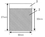
- the obtained secondary molded product is formed into a sheet having a thickness of 160 ⁇ m ⁇ 5% (8 ⁇ m) by a roll press, and then cut into a predetermined size (30 mm ⁇ 30 mm) to form an electrode composition as shown in FIG. 1 was produced. Then, the obtained electrode composition 1 was dried at 120 ° C. under a reduced pressure atmosphere for 16 hours or more, and then the mass, sheet thickness and dimensions were measured and used for the following measurements.
- the etched aluminum foil 3 manufactured by Hosen Co., Ltd. was coated with the conductive adhesive 2 “HITASOL GA-703” manufactured by Hitachi Kasei Kogyo Co., Ltd. so that the coating thickness was 100 ⁇ m. Then, as shown in FIG. 3, the etched aluminum foil 3 coated with the conductive adhesive 2 and the previously cut sheet-shaped electrode composition 1 were adhered to each other. Then, a tab 4 with an aluminum sealant 5 manufactured by Hosen Co., Ltd. was welded to the etched aluminum foil 3 using an ultrasonic welding machine. After welding, it was vacuum dried at 120 ° C. to obtain a polar electrode 6 provided with an aluminum current collector.
- the etched aluminum foil 3 manufactured by Hosen Co., Ltd. was coated with the conductive adhesive 2 “HITASOL GA-703” manufactured by Hitachi Kasei Kogyo Co., Ltd. so that the coating thickness was 100 ⁇ m. Then, as shown in FIG. 3, the etched aluminum foil 3 coated with the conductive adhesive 2 and the previously cut sheet
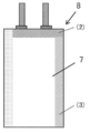
- an aluminum laminated resin sheet manufactured by Hosen Co., Ltd. is cut into a rectangle (length 200 mm ⁇ width 60 mm), folded in half, and one side ((1) in FIG. 4) is thermocompression bonded.
- a bag-shaped exterior sheet 7 having the remaining two sides open was prepared.
- a laminated body in which two of the above polar electrodes 6 were laminated was produced via a cellulose separator "TF-40" (not shown) manufactured by Nippon Kodoshi Kogyo Co., Ltd. This laminated body was inserted into the exterior sheet 7, and one side ((2) in FIG. 5) in contact with the tab 4 was thermocompression bonded to fix the polar electrode 6. Then, after vacuum-drying at 120 ° C.
- the electrolytic solution was injected in a dry box in an argon atmosphere (dew point ⁇ 90 ° C. or lower).
- an acetonitrile solution of 1.0 mol / L tetraethylammonium tetrafluoroborate manufactured by Kishida Scientific Co., Ltd. was used as the electrolytic solution.
- the remaining one side ((3) in FIG. 5) of the exterior sheet 7 was thermocompression bonded to prepare the electric double layer capacitor 8 shown in FIG. ..
- the obtained electric double layer capacitor 8 is constantly charged at 25 ° C. and -30 ° C. at 25 ° C. and ⁇ 30 ° C. at a constant current of 50 mA per electrode surface area up to a maximum voltage of 3.0 V using “CAPACITOR TESTER PFX2411” manufactured by Kikusui Electronics Co., Ltd. Further, the supplementary charge was performed at 3.0 V for 30 minutes under a constant voltage, and after the supplementary charge was completed, the battery was discharged at 25 mA. The obtained discharge curve data was calculated by the energy conversion method and used as the capacitance (F).
- the capacitance measurement described above After the capacitance measurement described above, it was held for 600 hours while applying a voltage of 3.0 V in a constant temperature bath at 60 ° C.
- the dry weight of the measurement electrode cell and the weight in water are measured, the cell volume is obtained from the generated buoyancy and water density, and the gas volume calculated from the change in cell volume before and after the durability test is corrected by the temperature difference at the time of measurement. I asked. That is, the amount of gas generated was calculated according to the following formula.
- the cell weight A represents the cell weight (g) in the air
- the cell weight W represents the cell weight (g) in water.
- Gas generation amount (cc) ⁇ (Cell weight A after endurance test-Cell weight W after endurance test) -(Cell weight A before endurance test-Cell weight W before endurance test) ⁇ / (273 + measured temperature after endurance test (° C)) / (273 + measured temperature before endurance test (° C))
- the value obtained by further dividing the above gas generation amount by the mass of activated carbon constituting the electrode composition was taken as the gas generation amount (cc / g) per activated carbon mass. The results are shown in Table 2.
- the carbonaceous materials obtained in Examples 1 to 9 have excellent moldability, and the electric double layer capacitor provided with the electrode for the electric double layer capacitor made from the carbonaceous material has a small amount of gas generation. It can be seen that it has a high initial capacity.
- the carbonaceous material obtained in Comparative Example 9 is inferior in moldability, and the electric double layer capacitor provided with the electrode made from the carbonaceous material obtained in Comparative Example 6 has a low initial capacitance. It can be seen that the electric double layer capacitor provided with the electrode made of the carbonaceous material obtained in the comparative examples other than the above generates a large amount of gas.
- Electrode composition 2 Conductive adhesive 3 Etched aluminum foil 4 Tabs 5 Sealant 6-minute polar electrode 7 Bag-shaped exterior sheet 8 Electric double layer capacitor (1) Thermocompression bonded side (2) One side where tabs touch (3) Bag The remaining side of the exterior sheet
Landscapes
- Chemical & Material Sciences (AREA)
- Engineering & Computer Science (AREA)
- Organic Chemistry (AREA)
- Power Engineering (AREA)
- Inorganic Chemistry (AREA)
- Materials Engineering (AREA)
- Microelectronics & Electronic Packaging (AREA)
- Carbon And Carbon Compounds (AREA)
- Electric Double-Layer Capacitors Or The Like (AREA)
Abstract
本発明は、ケイ素元素の含有量が200ppm未満であり、粉体導電率が10.0~22.0S/cmであり、全表面官能基量が0.22~0.36meq/gであり、BJH法により測定される細孔径4nm以上の細孔容積が0.10~0.20cm3/gである、炭素質材料に関する。
Description
本特許出願は日本国特許出願第2019-234855号(出願日:2019年12月25日)についてパリ条約上の優先権を主張するものであり、ここに参照することによって、その全体が本明細書中へ組み込まれるものとする。
本発明は、炭素質材料、その製造方法、電気二重層キャパシタ用電極活物質、電気二重層キャパシタ用電極および電気二重層キャパシタに関する。
本発明は、炭素質材料、その製造方法、電気二重層キャパシタ用電極活物質、電気二重層キャパシタ用電極および電気二重層キャパシタに関する。
電気化学デバイスの1つである電気二重層キャパシタは、化学反応を伴わず物理的なイオンの吸脱着のみから得られる容量(電気二重層容量)を利用しているため、電池と比較して出力特性、寿命特性に優れている。その特性から、各種メモリーのバックアップ、自然エネルギーによる発電用途、UPS(Uninterruptible Power Supply)などの蓄電源用途として多く開発されている。近年では、電気二重層キャパシタは上記の優れた特性と、環境問題への早急な対策といった点から、電気自動車(EV)やハイブリッド車(HV)の補助電源、回生エネルギーの貯蔵用途として注目されている。このような車載用の電気化学デバイスには、より高エネルギー密度であることだけでなく、民生用途と比較して厳しい使用条件下(たとえば厳しい温度環境下)における高い耐久性や静電容量のさらなる向上が求められている。
このような要求に対し、電気化学デバイスの耐久性や静電容量を改善させるための方法が種々検討されている。例えば、特許文献1には、活性炭中の表面官能基だけではなく、骨格内酸素量を制限することで、充放電時のガス発生の抑制ができ、かつ低抵抗化にも有用である改質活性炭が開示されている。
特許文献2には、炭化物の賦活物をアルカリ洗浄および酸洗浄し、ケイ素含有量を200~3000ppmに低減させることで、静電容量が高く、電気抵抗が低減された電気二重層キャパシタ用活性炭が開示されている。
しかしながら、上記特許文献1に記載されている表面官能基および骨格内酸素量を制御する方法では、ガス発生抑制効果は十分満足いくものではなかった。特許文献2では、静電容量の向上に着目して、活性炭中のケイ素元素含有量を特定の範囲に規定しているが、前記範囲では静電容量の向上には一定の効果はあるものの、ガス発生抑制効果は必ずしも十分満足いくものではない可能性があった。
そこで、本発明は、電気二重層キャパシタの充放電時のガス発生を抑制し、かつ成形性および静電容量に優れた炭素質材料およびその製造方法を提供することを目的とする。
本発明者等は、上記課題を解決すべく鋭意検討を行った結果、本発明に至った。
即ち、本発明は、以下の好適な態様を包含する。
〔1〕ケイ素元素の含有量が200ppm未満であり、粉体導電率が10.0~22.0S/cmであり、全表面官能基量が0.22~0.36meq/gであり、BJH法により測定される細孔径4nm以上の細孔容積が0.10~0.20cm3/gである、炭素質材料。
〔2〕BET比表面積が1400~2200m2/gである、〔1〕に記載の炭素質材料。
〔3〕アルカリ金属の含有量が40ppm未満である、〔1〕または〔2〕に記載の炭素質材料。
〔4〕植物由来の炭素前駆体に基づく、〔1〕~〔3〕のいずれかに記載の炭素質材料。
〔5〕前記植物由来の炭素前駆体がヤシ殻である、〔1〕~〔4〕のいずれかに記載の炭素質材料。
〔6〕〔1〕~〔5〕のいずれかに記載の炭素質材料を含む、電気二重層キャパシタ用電極活物質。
〔7〕〔6〕に記載の電気二重層キャパシタ用電極活物質を含む、電気二重層キャパシタ用電極。
〔8〕〔7〕に記載の電気二重層キャパシタ用電極を備える、電気二重層キャパシタ。
〔9〕炭素前駆体を炭化後、賦活して得られる活性炭を、65℃以上のアルカリ性溶液中で洗浄する工程、および
前記アルカリ洗浄後の活性炭を酸洗浄後、不活性ガス雰囲気下、1000~1300℃で熱処理し、粉砕する工程、
を含む、〔1〕~〔5〕のいずれかに記載の炭素質材料の製造方法。
〔1〕ケイ素元素の含有量が200ppm未満であり、粉体導電率が10.0~22.0S/cmであり、全表面官能基量が0.22~0.36meq/gであり、BJH法により測定される細孔径4nm以上の細孔容積が0.10~0.20cm3/gである、炭素質材料。
〔2〕BET比表面積が1400~2200m2/gである、〔1〕に記載の炭素質材料。
〔3〕アルカリ金属の含有量が40ppm未満である、〔1〕または〔2〕に記載の炭素質材料。
〔4〕植物由来の炭素前駆体に基づく、〔1〕~〔3〕のいずれかに記載の炭素質材料。
〔5〕前記植物由来の炭素前駆体がヤシ殻である、〔1〕~〔4〕のいずれかに記載の炭素質材料。
〔6〕〔1〕~〔5〕のいずれかに記載の炭素質材料を含む、電気二重層キャパシタ用電極活物質。
〔7〕〔6〕に記載の電気二重層キャパシタ用電極活物質を含む、電気二重層キャパシタ用電極。
〔8〕〔7〕に記載の電気二重層キャパシタ用電極を備える、電気二重層キャパシタ。
〔9〕炭素前駆体を炭化後、賦活して得られる活性炭を、65℃以上のアルカリ性溶液中で洗浄する工程、および
前記アルカリ洗浄後の活性炭を酸洗浄後、不活性ガス雰囲気下、1000~1300℃で熱処理し、粉砕する工程、
を含む、〔1〕~〔5〕のいずれかに記載の炭素質材料の製造方法。
本発明によれば、電気二重層キャパシタの充放電時のガス発生を抑制し、かつ成形性および静電容量に優れた炭素質材料およびその製造方法を提供することができる。
以下、本発明の実施形態について、詳細に説明する。なお、本発明の範囲はここで説明する実施形態に限定されるものではなく、本発明の趣旨を損なわない範囲で種々の変更をすることができる。
<炭素質材料>
本発明の炭素質材料は、ケイ素元素の含有量が200ppm未満であり、粉体導電率が10.0~22.0S/cmであり、全表面官能基量が0.22~0.36meq/gであり、BJH法により測定される細孔径4nm以上の細孔容積が0.10~0.20cm3/gである。
本発明の炭素質材料は、ケイ素元素の含有量が200ppm未満であり、粉体導電率が10.0~22.0S/cmであり、全表面官能基量が0.22~0.36meq/gであり、BJH法により測定される細孔径4nm以上の細孔容積が0.10~0.20cm3/gである。
本発明の炭素質材料のケイ素元素含有量は、200ppm未満であり、100ppm未満であることが好ましく、50ppm未満であることがより好ましく、20ppm未満であることがさらに好ましい。ケイ素元素含有量が200ppm以上であると、充放電時のガス発生量が増加しやすくなる。また、本発明の炭素質材料のケイ素元素含有量の下限値は特に限定されないが、通常1ppm以上であり、5ppm以上であってもよい。本発明の炭素質材料のケイ素元素含有量は、後述の本発明の炭素質材料の製造方法における、アルカリ洗浄工程の洗浄液の濃度、温度等によって調整することができる。また、本発明の炭素質材料のケイ素元素含有量は例えば、後述の実施例に記載の通り、ICP(誘導結合プラズマ)発光分光法によって測定することができる。
本発明の炭素質材料の粉体導電率は、10.0S/cm以上であり、13.0S/cm以上であることが好ましく、14.0S/cm以上であることがより好ましく、14.5S/cm以上であることがさらにより好ましく、15.0S/cm以上であることが特に好ましい。また、本発明の炭素質材料の粉体導電率は、22.0S/cm以下であり、21.0S/cm以下であることが好ましく、20.0S/cm以下であることがより好ましい。粉体導電率が22.0S/cmを超える場合、炭素質材料の炭素結晶構造が過度に発達し、それに伴って炭素質材料の細孔が収縮されるため、重量当たりの初期静電容量の低下を及ぼし得る。一方、粉体導電率が10.0S/cm未満である場合、炭素質材料の炭素結晶構造の発達が十分ではなく、結晶性が低いことにより、炭素自身の電気伝導度が十分ではなく、充放電時の抵抗が増加するので、容量維持率が低下し得る。本発明の炭素質材料の粉体導電率は、後述の本発明の炭素質材料の製造方法における熱処理工程の熱処理温度等を調整することによって、上記範囲内に制御できる。また、本発明の炭素質材料の粉体導電率は、後述の実施例に記載の方法によって測定することができる。
本発明の炭素質材料の全表面官能基量は、0.22meq/g以上であり、0.23meq/g以上であることが好ましく、0.24meq/g以上であることがより好ましい。また、本発明の炭素質材料の全表面官能基量は、0.36meq/g以下であり、0.35meq/g以下であることが好ましく、0.34meq/g以下であることがより好ましい。全表面官能基量が0.36meq/gを超えると、キャパシタ用電極において電解液と反応する活性点が多くなり、電解液の分解反応を促進することにより、充放電時のガス発生量が増加しやすくなる。一方、全表面官能基量が0.22meq/g未満であると、疎水性が上昇することで活性炭粒子間、および活性炭粒子と他の材料との親和力が変化することにより、本発明の炭素質材料の成形性が悪くなり、前記炭素質材料から電極を作製することが困難になり得る。本発明の炭素質材料の全表面官能基量は、後述の本発明の炭素質材料の製造方法における熱処理工程の熱処理温度等を調整することによって上記範囲内に制御できる。本発明の炭素質材料の全表面官能基量は、後述の実施例に記載の方法によって測定することができる。
本発明の炭素質材料のBJH法により測定される細孔径4nm以上の細孔容積は、0.10cm3/g以上であり、0.11cm3/g以上であることが好ましく、0.13cm3/g以上であることがより好ましい。また、本発明の炭素質材料の細孔容積は、0.20cm3/g以下であり、0.18cm3/g以下であることが好ましく、0.17cm3/g以下であることがより好ましい。細孔径4nm以上の細孔容積が0.20cm3/gを超えると、電極のかさ密度が低下し、体積あたりの静電容量が低下しやすくなる。一方、細孔径4nm以上の細孔容積が0.10cm3/g未満であると、電極内部抵抗の上昇を招き、ガス発生量が増加しやすくなる。ここで、BJH法とは、CI法、DH法と同様に、一般にメソ孔(細孔直径2nm以上50nm以下の細孔)の解析に用いられる計算方法であり、Barrett、Joyner、Halendsらによって提唱された方法である。本発明においては、窒素吸着法によって測定した窒素吸着等温線に対し、実施例に記載の通りBJH法を適用することによって、細孔径4nm以上の細孔容積を算出することができる。本発明の炭素質材料の細孔径4nm以上の細孔容積は、使用する炭素前駆体の種類を適宜選択することによって、または後述する本発明の炭素質材料の製造方法における、賦活工程の温度や処理時間等を適宜調整することによって、上記範囲内に制御できる。
本発明の炭素質材料のMP法により測定されるミクロ孔(細孔直径2nm未満の細孔)の細孔容積は、0.60cm3/g以上であることが好ましく、0.63cm3/g以上であることがより好ましく、0.66cm3/g以上であることがさらに好ましい。また、上記ミクロ孔の細孔容積は、1.20cm3/g以下であることが好ましく、1.10cm3/g以下であることがより好ましく、1.00cm3/g以下であることがさらに好ましい。ミクロ孔の細孔容積が上記範囲内であると、細孔内での非水系電解質イオンの拡散抵抗によると思われる抵抗が減少する傾向にあり、また、電極の嵩密度が向上し、単位面積当たりの静電容量が高くなる傾向がある。ここで、MP法とは、HK法、SF法同様に、一般にミクロ孔解析に用いられる計算方法である。本発明において、窒素吸着法によって測定した窒素吸着等温線に対し、実施例に記載の通りMP法を適用することによって、ミクロ孔の細孔容積を算出することができる。本発明の炭素質材料のミクロ孔の細孔容積は、使用する炭素前駆体の種類を適宜選択することによって、または後述する本発明の炭素質材料の製造方法における、賦活工程の温度や処理時間等を適宜調整することによって、上記範囲内に制御できる。
本発明の炭素質材料のBET比表面積は、好ましくは1400m2/g以上であり、より好ましくは1430m2/g以上であり、さらに好ましくは1450m2/g以上であり、よりさらに好ましくは1500m2/g以上である。また本発明の炭素質材料のBET比表面積は、好ましくは2200m2/g以下であり、より好ましくは2150m2/g以下であり、さらに好ましくは2100m2/g以下、特に好ましくは2000m2/g未満である。BET比表面積が上記範囲内であると、細孔内での非水系電解質イオンの拡散抵抗によると思われる抵抗が減少する傾向にあり、また、電極の嵩密度が向上し、単位面積当たりの静電容量が高くなる傾向がある。本発明の炭素質材料のBET比表面積は、後述の本発明の炭素質材料の製造方法における、賦活工程の温度や処理時間等を適宜調整することによって、上記範囲内に制御できる。本発明の炭素質材料のBET比表面積は、例えば、後述の実施例に記載の窒素吸着等温線を測定する方法によって測定することができる。
本発明の炭素質材料のアルカリ金属含有量は、好ましくは40ppm未満であり、より好ましくは20ppm未満であり、さらに好ましくは10ppm未満である。本発明の炭素質材料のアルカリ金属含有量の下限値は特に限定されないが、0ppmであってもよく、通常1ppm以上であり、3ppm以上であってもよい。炭素質材料に含有され得るアルカリ金属種としては、リチウム、ナトリウム、カリウム、セシウム等が挙げられる。通常、含有量が多いのは、ナトリウムおよび/またはカリウムであるので、これらの含有量を制御することが重要となる。アルカリ金属含有量が上記範囲内であると、アルカリ金属元素が電解液中に溶出する可能性が低くなり再析出による短絡が起きにくくなる。また、アルカリ金属による炭素質材料の細孔の閉塞が起こりにくいため、充放電容量が高くなる傾向にある。本発明の炭素質材料のアルカリ金属含有量は、後述の本発明の炭素質材料の製造方法において、アルカリ洗浄や酸洗浄によって調整できる。本発明の炭素質材料のアルカリ金属含有量は、例えば、後述の実施例に記載のICP発光分光法によって測定することができる。
<炭素質材料の製造方法>
本発明の炭素質材料は、例えば
炭素前駆体を炭化後、賦活して得られる活性炭を、65℃以上のアルカリ性溶液中で洗浄する工程、および
前記アルカリ洗浄後の活性炭を酸洗浄後、不活性ガス雰囲気下、1000~1300℃で熱処理し、粉砕する工程、
を含む方法により製造することができる。
本発明の炭素質材料は、例えば
炭素前駆体を炭化後、賦活して得られる活性炭を、65℃以上のアルカリ性溶液中で洗浄する工程、および
前記アルカリ洗浄後の活性炭を酸洗浄後、不活性ガス雰囲気下、1000~1300℃で熱処理し、粉砕する工程、
を含む方法により製造することができる。
本発明において、炭素質材料の原料となる炭素前駆体は、賦活することによって炭素質材料を形成するものであれば特に限定されず、植物由来の炭素前駆体、鉱物由来の炭素前駆体、天然素材由来の炭素前駆体および合成素材由来の炭素前駆体などから広く選択することができる。有害不純物を低減する観点、環境保護の観点および商業的な観点からは、本発明の炭素質材料は、植物由来の炭素前駆体に基づくものであることが好ましく、言い換えると、本発明の炭素質材料となる炭素前駆体が植物由来であることが好ましい。
鉱物由来の炭素前駆体としては、例えば石油系および石炭系ピッチ、コークスが挙げられる。天然素材由来の炭素前駆体としては、例えば木綿、麻などの天然繊維、レーヨン、ビスコースレーヨンなどの再生繊維、アセテート、トリアセテートなどの半合成繊維が挙げられる。合成素材由来の炭素前駆体としては、例えばナイロンなどのポリアミド系、ビニロンなどのポリビニルアルコール系、アクリルなどのポリアクリロニトリル系、ポリエチレン、ポリプロピレンなどのポリオレフィン系、ポリウレタン、フェノール系樹脂、塩化ビニル系樹脂が挙げられる。
本発明において、植物由来の炭素前駆体としては、特に限定されないが、例えば木材、木炭、もみ殻、ヤシ殻、パーム殻などの果実殻、珈琲豆、茶葉、サトウキビ、果実(例えば、みかん、バナナ)、藁、籾殻、広葉樹、針葉樹、竹が例示されるが、これらに限定されない。この例示は、本来の用途に供した後の廃棄物(例えば、使用済みの茶葉)、あるいは植物原料の一部(例えば、バナナやみかんの皮)を包含する。これらの植物原料を、単独で使用してもよいし、2種以上を組み合わせて使用してもよい。これらの植物原料の中でも、入手が容易で種々の特性を有する炭素質材料を製造できることから、ヤシ殻が好ましい。
ヤシ殻としては、特に限定されないが、例えばパームヤシ(アブラヤシ)、ココヤシ、サラク、オオミヤシ等のヤシ殻が挙げられる。これらのヤシ殻を、単独で使用してもよいし、2種以上を組み合わせて使用してもよい。ヤシを、食品、洗剤原料、バイオディーゼル油原料等として利用した後に大量に発生するバイオマス廃棄物であるココヤシおよびパームヤシのヤシ殻が、入手容易性の観点から特に好ましい。
ヤシ殻を仮焼成してチャー(ヤシ殻チャー)の形態で入手することが可能で、これを素原料として使用することが好ましい。ここで、チャーとは、一般的には石炭を加熱した際に溶融軟化しないで生成する炭素分に富む粉末状の固体をいうが、ここでは有機物を加熱し、溶融軟化しないで生成する炭素分に富む粉末状の固体も指すこととする。ヤシ殻からチャーを製造する方法は、特に限定されるものではなく、当該分野において既知の方法を用いて製造することができる。例えば、原料となるヤシ殻を、例えば、窒素、二酸化炭素、ヘリウム、アルゴン、一酸化炭素もしくは燃料排ガスなどの不活性ガス、これら不活性ガスの混合ガス、またはこれら不活性ガスを主成分とする他のガスとの混合ガスの雰囲気下、400~800℃程度の温度で焼成(炭化処理)することによって製造することができる。
<賦活工程>
本発明の炭素質材料の製造方法において用いられるヤシ殻由来の活性炭は、例えば、上記炭素前駆体(ヤシ殻チャー)を賦活処理することにより、得ることができる。賦活処理とは、炭素前駆体の表面に細孔を形成し多孔質の炭素質物質に変える処理であり、これにより大きな比表面積および細孔容積を有する活性炭を得ることができる。賦活処理を行わず、炭素前駆体をそのまま用いた場合には、得られる炭素質物質の比表面積や細孔容積が十分でなく、電極材料に用いた場合に、十分に高い初期容量を確保することが困難であり、本発明の炭素質材料を得ることはできない。賦活処理は、当該分野において一般的な方法により行うことができ、主に、ガス賦活処理と薬剤賦活処理の2種類の処理方法を挙げることができる。
本発明の炭素質材料の製造方法において用いられるヤシ殻由来の活性炭は、例えば、上記炭素前駆体(ヤシ殻チャー)を賦活処理することにより、得ることができる。賦活処理とは、炭素前駆体の表面に細孔を形成し多孔質の炭素質物質に変える処理であり、これにより大きな比表面積および細孔容積を有する活性炭を得ることができる。賦活処理を行わず、炭素前駆体をそのまま用いた場合には、得られる炭素質物質の比表面積や細孔容積が十分でなく、電極材料に用いた場合に、十分に高い初期容量を確保することが困難であり、本発明の炭素質材料を得ることはできない。賦活処理は、当該分野において一般的な方法により行うことができ、主に、ガス賦活処理と薬剤賦活処理の2種類の処理方法を挙げることができる。
ガス賦活処理としては、例えば、水蒸気、二酸化炭素、空気、酸素、燃焼ガス、またはこれらの混合ガスの存在下、炭素前駆体を加熱する方法が知られている。また、薬剤賦活処理としては、例えば、塩化亜鉛、塩化カルシウム、リン酸、硫酸、水酸化ナトリウム、水酸化カリウム、水酸化マグネシウム、水酸化カルシウムなどの賦活剤を炭素前駆体と混合し、不活性ガス雰囲気下で加熱する方法が知られている。本発明においては、薬剤賦活は残留する薬剤を取り除く工程が必要となり、製造方法が煩雑となるためガス賦活処理を用いることが好ましい。
ガス賦活処理として水蒸気賦活を採用する場合、効率良く賦活を進行させる観点から、炭化処理の際に用いたものと同様の不活性ガスと水蒸気との混合物を用いることが好ましく、その際の水蒸気の分圧は10~60%の範囲であることが好ましい。水蒸気分圧が10%以上であると賦活を十分に進行させやすく、60%以下であると、急激な賦活反応を抑制し、反応をコントロールしやすい。
水蒸気賦活において供給する賦活ガスの総量は、炭素前駆体100質量部に対して、好ましくは50~10000質量部、より好ましくは100~5000質量部、さらに好ましくは200~3000質量部である。供給する賦活ガスの総量が上記範囲内であると、賦活反応をより効率よく進行させることができる。
原料となるヤシ殻由来の活性炭の比表面積や細孔容積は、炭素前駆体の賦活処理方法およびその条件等を変えることにより制御することができる。例えば、水蒸気賦活処理により賦活活性炭を得る場合、用いるガスや加熱温度および時間等により制御することができる。水蒸気賦活処理において、得られる賦活活性炭の比表面積や細孔径は、加熱温度が低いと小さくなる傾向にあり、加熱温度が高いと大きくなる傾向にある。本発明において、水蒸気賦活処理により賦活活性炭を得る場合、その加熱温度(賦活温度)は用いるガスの種類にもよるが、通常700~1100℃であり、800~1000℃であることが好ましい。また、加熱時間や昇温速度は特に限定されるものではなく、加熱温度、所望する賦活活性炭の比表面積等に応じて適宜決定すればよい。
必要に応じて、賦活処理は1回または2回以上実施しても良い。賦活処理を2回以上実施する場合は、例えば、1回目の賦活(以下一次賦活ともいう)後の活性炭(以下一次賦活活性炭ともいう)を、アルカリ金属等の不純物を除去する目的で、酸を用いて洗浄する工程を含んでいてもよい。酸洗浄工程は、賦活後の活性炭を、酸を含む洗浄液に浸漬することによって行うことができる。酸洗浄後、残留した酸を除去するために水、好ましくはイオン交換水で十分に洗浄して乾燥後、一次洗浄活性炭が得られる。この一次洗浄活性炭を再度賦活処理することで、二次賦活活性炭が得られる。以下では1回目または2回目以降の賦活処理を実施した活性炭を合わせて、賦活活性炭と称する。
前記賦活後の酸洗浄の条件は、特に限定はなく、用いる酸の種類、濃度、洗浄温度や洗浄時間等は適宜調整してよい。好ましい一実施態様において、例えば酸の種類:塩酸、硝酸、硫酸、又はそれらの混合物、好ましくは塩酸;濃度:0.01~5N、好ましくは0.1~2N;洗浄温度:40~120℃、好ましくは60~100℃;洗浄時間:5分~6時間、好ましくは10分~3時間として、酸洗浄を行ってもよい。
2回目以降の賦活の条件も限定はなく、一次賦活と同様に、加熱温度や加熱時間等は所望する賦活活性炭の比表面積等に応じて適宜決定すればよい。
<アルカリ洗浄工程>
本発明の炭素質材料の製造方法は、賦活後の賦活活性炭を65℃以上のアルカリ性溶液で洗浄する工程を含む。アルカリ洗浄工程は、前記賦活活性炭を、65℃以上のアルカリ性洗浄液により洗浄することにより、前記賦活活性炭中に含まれるケイ素元素を除去するための工程である。アルカリ洗浄工程は、賦活後に得られた賦活活性炭を、65℃以上の洗浄液に浸漬すること等によって行うことができる。前記洗浄液としては、例えば、水酸化ナトリウム水溶液、水酸化カリウム、水酸化リチウム等が挙げられるが、入手の容易さから、水酸化ナトリウム水溶液であることが好ましい。
本発明の炭素質材料の製造方法は、賦活後の賦活活性炭を65℃以上のアルカリ性溶液で洗浄する工程を含む。アルカリ洗浄工程は、前記賦活活性炭を、65℃以上のアルカリ性洗浄液により洗浄することにより、前記賦活活性炭中に含まれるケイ素元素を除去するための工程である。アルカリ洗浄工程は、賦活後に得られた賦活活性炭を、65℃以上の洗浄液に浸漬すること等によって行うことができる。前記洗浄液としては、例えば、水酸化ナトリウム水溶液、水酸化カリウム、水酸化リチウム等が挙げられるが、入手の容易さから、水酸化ナトリウム水溶液であることが好ましい。
アルカリ洗浄を行う際の液温度は65℃以上であり、70℃以上あることが好ましく、80℃以上であることがさらに好ましい。液温度の上限は、110℃以下であることが好ましく、105℃以下であることがより好ましく、100℃以下であることが特に好ましい。液温度が上記範囲であると、賦活活性炭中のケイ素元素濃度を十分に低減させることができ、かつ安全に実施できるため好ましい。
洗浄液中のアルカリの濃度は特に限定されるものではなく、用いる洗浄液の種類に応じて濃度を適宜調整してよい。洗浄液のアルカリ濃度は、0.01N以上であることが好ましく、0.03N以上であることがさらに好ましい。アルカリ濃度の上限値は10N以下であることが好ましく、5N以下であることがさらに好ましい。アルカリ濃度が低過ぎると、ケイ素元素を除去するために洗浄回数を増やす必要があり、逆に高過ぎると、残留するアルカリ成分が多くなることから、上記範囲の濃度とすることにより、効率よくアルカリ洗浄工程を行うことができ、生産性の面から好ましい。
アルカリ洗浄の洗浄液のpHは、特に限定されるものではなく、用いる洗浄液の種類等に応じて適宜調節してよいが、12以上が洗浄時間または洗浄回数を減らせる点で好ましい。
賦活活性炭を洗浄液に浸漬する際の、洗浄液と賦活活性炭との質量割合は、用いる洗浄液の種類、濃度および温度等に応じて適宜調節してよい。洗浄液の質量に対する、浸漬させる賦活活性炭の質量は、2質量%以上であることが好ましく、5質量%以上であることがさらに好ましい。質量割合の上限は、50質量%以下であることが好ましく、30質量%以下であることがさらに好ましい。上記範囲内であると、洗浄液を昇温させる為に過剰のエネルギーを必要とせず、かつ十分な洗浄効果が得られるため好ましい。
アルカリ洗浄を行う雰囲気は特に限定されず、洗浄に使用する方法に応じて適宜選択してよい。本発明において洗浄は、通常、大気雰囲気中で実施する。
賦活活性炭をアルカリ洗浄する方法としては、賦活活性炭を洗浄液に浸漬させることができる限り特に限定されず、洗浄液を連続的に添加し、所定の時間滞留させ、抜き取りながら浸漬を行う方法でも、賦活活性炭を洗浄液に浸漬し、所定の時間滞留させ、脱液した後、新たに洗浄液を添加して浸漬-脱液を繰り返す方法であってもよい。また、洗浄液の全部を更新する方法であってもよいし、洗浄液の一部を更新する方法であってもよい。また、浸漬時に洗浄液を攪拌してもよい。
賦活活性炭を洗浄液に浸漬する時間としては、用いる洗浄液、処理温度等に応じて適宜調節することができるが、賦活活性炭中のケイ素が十分低減することから5分以上が好ましく、生産性の観点から50分以下が好ましく、40分以下がより好ましく、35分以下がさらにより好ましく、30分以下がまたさらに好ましい。
賦活活性炭をアルカリ洗浄後、残留した洗浄液を除去するため、賦活活性炭を水洗してもよい。
<酸洗浄工程>
本発明の炭素質材料の製造方法は、アルカリ洗浄後の賦活活性炭を酸性溶液で洗浄する工程を含む。アルカリ洗浄後の酸洗浄工程は、前記アルカリ洗浄後の賦活活性炭を、酸性洗浄液により洗浄することにより、金属などの不純物を除去するための工程である。アルカリ洗浄後の酸洗浄工程は、アルカリ洗浄後に得られた賦活活性炭を、酸性洗浄液に浸漬すること等によって行うことができる。洗浄液としては、例えば、塩酸、硝酸、硫酸等が挙げられるが、炭を酸化することがない点から、塩酸であることが好ましい。
本発明の炭素質材料の製造方法は、アルカリ洗浄後の賦活活性炭を酸性溶液で洗浄する工程を含む。アルカリ洗浄後の酸洗浄工程は、前記アルカリ洗浄後の賦活活性炭を、酸性洗浄液により洗浄することにより、金属などの不純物を除去するための工程である。アルカリ洗浄後の酸洗浄工程は、アルカリ洗浄後に得られた賦活活性炭を、酸性洗浄液に浸漬すること等によって行うことができる。洗浄液としては、例えば、塩酸、硝酸、硫酸等が挙げられるが、炭を酸化することがない点から、塩酸であることが好ましい。
アルカリ洗浄後の酸洗浄液中の酸の濃度は特に限定されるものではなく、用いる洗浄液の種類に応じて濃度を適宜調整してよい。洗浄液の酸濃度は、0.01N以上であることが好ましく、0.1N以上であることがさらに好ましい。酸濃度の上限は、5N以下であることが好ましく、2N以下であることがさらに好ましい。酸濃度が低過ぎると、洗浄回数を増やす必要があり、逆に高過ぎると、残留する酸成分が多くなることから、上記範囲の濃度とすることにより、効率よく酸洗浄工程を行うことができ、生産性の面から好ましい。
アルカリ洗浄後の酸洗浄液のpHは、特に限定されるものではなく、用いる洗浄液の種類等に応じて適宜調節してよいが、洗浄回数を減らせる点でpH2以下であることが好ましい。
アルカリ洗浄後の酸洗浄液の液温度は、特に限定されるものではなく、用いる洗浄液の種類等に応じて適宜調節してよいが、金属除去能力が高い点で40℃~100℃であることが好ましい。
賦活活性炭を酸洗浄液に浸漬する際の、洗浄液と賦活活性炭との質量割合は、用いる洗浄液の種類、濃度および温度等に応じて適宜調節してよい。洗浄液の質量に対する、浸漬させる賦活活性炭の質量は、2質量%以上であることが好ましく、5質量%以上であることがさらに好ましい。質量割合の上限は、50質量%以下であることが好ましく、30質量%以下であることがさらに好ましい。上記下限値以下であると、洗浄液を昇温させる為に多くのエネルギーが必要になる可能性があり、上記上限値以上であると十分な洗浄効果が得られにくい。
アルカリ洗浄後の酸洗浄を行う雰囲気は特に限定されず、洗浄に使用する方法に応じて適宜選択してよい。本発明において洗浄は、通常、大気雰囲気中で実施する。
賦活活性炭を洗浄する方法としては、賦活活性炭を洗浄液に浸漬させることができる限り特に限定されず、洗浄液を連続的に添加し、所定の時間滞留させ、抜き取りながら浸漬を行う方法でも、賦活活性炭を洗浄液に浸漬し、所定の時間滞留させ、脱液した後、新たに洗浄液を添加して浸漬-脱液を繰り返す方法であってもよい。また、洗浄液の全部を更新する方法であってもよいし、洗浄液の一部を更新する方法であってもよい。賦活活性炭を洗浄液に浸漬する時間としては、用いる洗浄液、処理温度等に応じて適宜調節することができるが、金属を十分除去する為に5分以上が好ましく、10分以上であるとより好ましい。
酸洗浄後、賦活活性炭を水洗してもよい。また、本発明の炭素質材料の製造方法は、賦活活性炭に残留する酸洗浄液に由来する酸を除去するため、脱酸工程を含んでいてもよい。本発明において、脱酸工程とは、酸洗浄後の賦活活性炭に残留する酸を除去する工程を指し、酸化性ガス雰囲気下で短時間加熱する方法が好ましい。
酸化性ガスとしては、例えば、酸素、水蒸気、炭酸ガス、灯油やプロパンを燃焼して得られる燃焼ガスなどが挙げられる。これらのガスは、1種類のみ単独で用いてもよく、また、2種類以上を混合した混合ガスとして用いてもよい。
酸化性ガス雰囲気下での加熱時間や温度は特に限定されないが、調製した細孔構造を大きく変化させないことから500℃~1000℃で5分~60分処理することが好ましい。
<熱処理工程>
本発明の炭素質材料の製造方法は、熱処理工程を含む。前記アルカリ洗浄および酸洗浄工程後の活性炭(以下アルカリおよび酸洗浄活性炭ともいう)を熱処理することによって、炭素構造を発達させ、導電率を所望の範囲に制御することができる。また、本工程で表面官能基量は所望の範囲より低減することもあるが、後述の粉砕工程を本熱処理工程後に実施することで、所望の範囲に制御することができる。熱処理温度の下限は1000℃以上が好ましく、1100℃以上がより好ましく、1100℃超がさらに好ましく、1150℃以上がよりさらに好ましい。熱処理温度の上限は1300℃以下が好ましく、1250℃以下がより好ましい。熱処理温度が低すぎると、炭素構造の発達が不十分で有り導電率が所望の値に達しにくい。また、熱処理温度が高すぎると、細孔収縮が生じ、電気化学デバイスに用いた際に、十分に高い初期静電容量を確保することが困難な場合がある。所望の温度に達してからの熱処理時間は、炭素構造を十分に発達させ、細孔収縮させすぎない点から10分~120分であることが好ましい。昇温速度は、熱処理工程の時間が長くなりすぎず、設備の劣化を抑制する観点から2℃/分~20℃/分であることが好ましい。
本発明の炭素質材料の製造方法は、熱処理工程を含む。前記アルカリ洗浄および酸洗浄工程後の活性炭(以下アルカリおよび酸洗浄活性炭ともいう)を熱処理することによって、炭素構造を発達させ、導電率を所望の範囲に制御することができる。また、本工程で表面官能基量は所望の範囲より低減することもあるが、後述の粉砕工程を本熱処理工程後に実施することで、所望の範囲に制御することができる。熱処理温度の下限は1000℃以上が好ましく、1100℃以上がより好ましく、1100℃超がさらに好ましく、1150℃以上がよりさらに好ましい。熱処理温度の上限は1300℃以下が好ましく、1250℃以下がより好ましい。熱処理温度が低すぎると、炭素構造の発達が不十分で有り導電率が所望の値に達しにくい。また、熱処理温度が高すぎると、細孔収縮が生じ、電気化学デバイスに用いた際に、十分に高い初期静電容量を確保することが困難な場合がある。所望の温度に達してからの熱処理時間は、炭素構造を十分に発達させ、細孔収縮させすぎない点から10分~120分であることが好ましい。昇温速度は、熱処理工程の時間が長くなりすぎず、設備の劣化を抑制する観点から2℃/分~20℃/分であることが好ましい。
熱処理は、不活性ガス条件下、あるいは酸素または空気を遮断し、活性炭から発生するガス雰囲気下で行うことが好ましい。熱処理に用いられる不活性ガスとしては、例えば、窒素ガス、アルゴンガス、ヘリウムガス等が挙げられる。これらのガスは、1種のみを単独で用いてもよく、また、2種以上を混合した混合ガスとして用いてもよい。
熱処理に用いる炉としては、ロータリキルン、流動層炉、固定層炉、移動層炉、移動床炉等各種形式の炉を使用することができ、原料の投入、製品の取り出しを連続的に行う連続炉、間欠的に行うバッチ炉の双方とも適用することができる。加熱手段としては所定の温度まで加熱可能な手段であれば問題なく、電気加熱やガス燃焼型加熱、高周波誘導加熱、通電加熱などが適用できる。また、これら加熱手段は単独で使用してもよいし、併用しても構わない。
<粉砕工程>
本発明の炭素質材料の製造方法は、熱処理工程後に粉砕工程を含む。粉砕工程は、最終的に得られる炭素質材料の形状や粒径を所望する形状や粒径に制御するための工程である。粉砕工程によって、表面官能基量を適切な範囲に制御できるため、炭素質材料の成形性を向上させることができる。本発明の炭素質材料の粒子径は、特に限定されないが、電気二重層キャパシタ用途に使用する場合、平均粒子径は好ましくは1~15μm、より好ましくは2~10μmとなるよう炭素質材料を粉砕することが好ましい。
本発明の炭素質材料の製造方法は、熱処理工程後に粉砕工程を含む。粉砕工程は、最終的に得られる炭素質材料の形状や粒径を所望する形状や粒径に制御するための工程である。粉砕工程によって、表面官能基量を適切な範囲に制御できるため、炭素質材料の成形性を向上させることができる。本発明の炭素質材料の粒子径は、特に限定されないが、電気二重層キャパシタ用途に使用する場合、平均粒子径は好ましくは1~15μm、より好ましくは2~10μmとなるよう炭素質材料を粉砕することが好ましい。
粉砕に用いる粉砕機は、特に限定されるものではなく、例えば、コーンクラッシャー、ダブルロールクラッシャー、ディスククラッシャー、ロータリークラッシャー、ボールミル、遠心ロールミル、リングロールミル、遠心ボールミル、ジェットミルなどの公知の粉砕機を、単独でまたは組み合わせて用いることができる。
<分級工程>
本発明において、炭素質材料の製造方法は分級工程を含んでもよい。例えば、所望の粒子径より極端に小さいまたは大きい粒子を除くことにより、狭い粒度分布幅を有する炭素質材料粒子を得ることが可能となる。これにより、電極構成時のバインダー量を少なくすることが可能となる。分級方法は、特に制限されないが、例えば篩を用いた分級、湿式分級、乾式分級を挙げることができる。湿式分級機としては、例えば重力分級、慣性分級、水力分級、遠心分級等の原理を利用した分級機を挙げることができる。乾式分級機としては、沈降分級、機械的分級、遠心分級等の原理を利用した分級機を挙げることができる。経済性の観点から、乾式分級装置を用いることが好ましい。
本発明において、炭素質材料の製造方法は分級工程を含んでもよい。例えば、所望の粒子径より極端に小さいまたは大きい粒子を除くことにより、狭い粒度分布幅を有する炭素質材料粒子を得ることが可能となる。これにより、電極構成時のバインダー量を少なくすることが可能となる。分級方法は、特に制限されないが、例えば篩を用いた分級、湿式分級、乾式分級を挙げることができる。湿式分級機としては、例えば重力分級、慣性分級、水力分級、遠心分級等の原理を利用した分級機を挙げることができる。乾式分級機としては、沈降分級、機械的分級、遠心分級等の原理を利用した分級機を挙げることができる。経済性の観点から、乾式分級装置を用いることが好ましい。
粉砕と分級とを、1つの装置を用いて実施することもできる。例えば、乾式の分級機能を備えたジェットミルを用いて、粉砕および分級を実施することができる。更に、粉砕機と分級機とが独立した装置を用いることもできる。この場合、粉砕と分級とを連続して行うこともできるが、粉砕と分級とを不連続に行うこともできる。
本発明の炭素質材料は、電気二重層キャパシタ用電極活物質等として好適に用いることができる。本発明の炭素質材料を用いることにより、充放電時のガス発生量が少なく、静電容量に優れた電気二重層キャパシタとすることができる。したがって、本発明の一実施態様においては、本発明の炭素質材料を含む、電気二重層キャパシタ用電極活物質を提供することができ、該活物質を含む電気二重層キャパシタ用電極を提供することができ、また、該電極を備える電気二重層キャパシタを提供することができる。
本発明の電気二重層キャパシタ用電極活物質は、本発明の炭素質材料を用いることにより製造できる。例えば原料となる本発明の炭素質材料と、導電性付与剤、バインダー、溶剤等の成分を混錬する工程、混錬物を塗工・乾燥する工程等の電極材料の製造工程として従来当該分野において一般的な製造工程を含むことができる。また、前記電気二重層キャパシタ用電極は、前記電極活物質を用いることにより製造でき、その製造工程としては、例えば、原料となる前記電極活物質に溶剤を添加してペーストを調製する工程、前記ペーストをアルミ箔等の集電板に塗布した後、溶媒を乾燥除去する工程、前記ペーストを金型に入れプレス成形する工程を含むことができる。
この電極に使用される導電性付与剤としては、例えば、アセチレンブラック、ケッチェンブラック等を用いることができる。バインダーとしては、例えば、ポリテトラフルオロエチレン、ポリフッ化ビニリデン等のフッ素系高分子化合物や、カルボキシメチルセルロース、スチレン-ブタジエンゴム、石油ピッチ、フェノール樹脂等を用いることができる。また、溶剤としては、例えば、水、メタノール、エタノールなどのアルコール類、ヘキサン、ヘプタンなどの飽和炭化水素、トルエン、キシレン、メシチレンなどの芳香族炭化水素、アセトン、エチルメチルケトンなどのケトン類、酢酸メチル、酢酸エチルなどのエステル類、N,N-ジメチルホルムアミド、N,N-ジエチルホルムアミドなどのアミド類、N-メチルピロリドン、N-エチルピロリドンなどの環状アミド類等を用いることができる。
本発明の電気二重層キャパシタは、前記電極を備えることを特徴とする。電気二重層キャパシタは、一般に、電極、電解液、およびセパレータを主要構成とし、一対の電極間にセパレータを配置した構造となっている。電解液としては、例えば、プロピレンカーボネート、エチレンカーボネート、メチルエチルカーボネート等の有機溶剤にアミジン塩を溶解した電解液、過塩素酸の4級アンモニウム塩を溶解した電解液、4級アンモニウムやリチウム等のアルカリ金属の四フッ化ホウ素塩や六フッ化リン塩を溶解した電解液、4級ホスホニウム塩を溶解した電解液等が挙げられる。また、セパレータとしては、例えば、セルロース、ガラス繊維、または、ポリエチレンやポリプロピレン等のポリオレフィンを主成分とした不織布、クロス、微孔フィルムが挙げられる。電気二重層キャパシタは、例えば、これらの主要な構成を、従来当該分野において一般的な方法により配置することにより製造することができる。
本発明の炭素質材料は成形性に優れており、該炭素質材料から製造された電極を備える電気二重層キャパシタは、充放電時のガス発生抑制効果が高く、優れた静電容量を有している。
以下、実施例によって本発明を具体的に説明するが、これらは本発明の範囲を限定するものではない。
実施例中の物性値の測定は以下に記載の方法に従って行った。
<ケイ素元素、ナトリウム元素、およびカリウム元素の含有量>
ケイ素元素、ナトリウム元素、およびカリウム元素の含有量は、以下の方法により測定した。まず、既知濃度の標準液からケイ素元素、ナトリウム元素、およびカリウム元素含有量についての検量線を作成する。ついで、粉砕した測定試料を115℃で3時間乾燥した後、分解容器に0.1g入れ、硝酸10mlを加え混ぜた後、マイクロウェーブ試料前処理装置(CEM社製「MARS6」)を用いて試料を溶解した。その溶解液を取り出し、25mlにメスアップして測定溶液を調製した後、ICP発光分光分析装置((株)島津製作所製「ICPE-9820」)にて分析した。得られた値と先に作成した検量線より各濃度を求め、下記の式より各元素含有量を求めた。
ケイ素元素、ナトリウム元素、およびカリウム元素の含有量は、以下の方法により測定した。まず、既知濃度の標準液からケイ素元素、ナトリウム元素、およびカリウム元素含有量についての検量線を作成する。ついで、粉砕した測定試料を115℃で3時間乾燥した後、分解容器に0.1g入れ、硝酸10mlを加え混ぜた後、マイクロウェーブ試料前処理装置(CEM社製「MARS6」)を用いて試料を溶解した。その溶解液を取り出し、25mlにメスアップして測定溶液を調製した後、ICP発光分光分析装置((株)島津製作所製「ICPE-9820」)にて分析した。得られた値と先に作成した検量線より各濃度を求め、下記の式より各元素含有量を求めた。

<粉体導電率>
(株)三菱化学アナリテック社製、粉体抵抗率測定ユニット「MCP-PD51」を使用し、炭素質材料の導電率を測定した。導電率の測定は、荷重を12kNかけた際の活性炭ペレットの厚みが3.5~4.5mmとなる量の試料を使用し、荷重を12kNかけた状態での活性炭ペレットの導電率を測定した。
(株)三菱化学アナリテック社製、粉体抵抗率測定ユニット「MCP-PD51」を使用し、炭素質材料の導電率を測定した。導電率の測定は、荷重を12kNかけた際の活性炭ペレットの厚みが3.5~4.5mmとなる量の試料を使用し、荷重を12kNかけた状態での活性炭ペレットの導電率を測定した。
<表面官能基量>
表面官能基量は、H.P.Boehm,Advan.Catal.,1966,16,179等により公知の塩酸滴定法によって測定した。具体的には、(株)高純度化学研究所製のナトリウムエトキシドを用いて、0.1Nのエタノール溶液を測定溶液として調製した。この測定溶液25mlに、試料となる炭素質材料を0.5g加え、25℃で24時間撹拌した。撹拌後、遠心分離にて測定溶液と炭素質材料とを分離し、当該測定溶液10mlを採取し、スイスMetrohm社製「888Titrando」を用いて、0.1Nの塩酸でpH4.0となる点を滴定終点として中和滴定を行い、試料滴定量を求めた。一方、試料を含まない溶液で空試験を行い、空試験滴定量も求め、下記式により表面官能基量を算出した。
表面官能基量(meq/g)=
{空試験滴定量(mL)-試料滴定量(mL)}×0.1×f(塩酸ファクター)/
使用した炭素質材料重量(g)×25(mL)/10(mL)
表面官能基量は、H.P.Boehm,Advan.Catal.,1966,16,179等により公知の塩酸滴定法によって測定した。具体的には、(株)高純度化学研究所製のナトリウムエトキシドを用いて、0.1Nのエタノール溶液を測定溶液として調製した。この測定溶液25mlに、試料となる炭素質材料を0.5g加え、25℃で24時間撹拌した。撹拌後、遠心分離にて測定溶液と炭素質材料とを分離し、当該測定溶液10mlを採取し、スイスMetrohm社製「888Titrando」を用いて、0.1Nの塩酸でpH4.0となる点を滴定終点として中和滴定を行い、試料滴定量を求めた。一方、試料を含まない溶液で空試験を行い、空試験滴定量も求め、下記式により表面官能基量を算出した。
表面官能基量(meq/g)=
{空試験滴定量(mL)-試料滴定量(mL)}×0.1×f(塩酸ファクター)/
使用した炭素質材料重量(g)×25(mL)/10(mL)
<窒素吸着等温線>
マイクロトラック・ベル(株)製のBELSORP-miniを使用し、試料となる炭素質材料を窒素気流下(窒素流量:50mL/分)にて300℃で3時間加熱した後、77Kにおける炭素質材料の窒素吸着等温線を測定した。
マイクロトラック・ベル(株)製のBELSORP-miniを使用し、試料となる炭素質材料を窒素気流下(窒素流量:50mL/分)にて300℃で3時間加熱した後、77Kにおける炭素質材料の窒素吸着等温線を測定した。
<4nm以上の細孔容積>
得られた窒素吸着等温線に対し、BJH法を用いて相対圧P/P0=0.99以下の範囲で算出される4nm以上の細孔径を有する細孔の細孔容積を求めた。なお、BJH法での解析にあたってはマイクロトラック・ベル(株)から提供された基準t曲線『NGCB-BEL.t』を解析に用いた。
得られた窒素吸着等温線に対し、BJH法を用いて相対圧P/P0=0.99以下の範囲で算出される4nm以上の細孔径を有する細孔の細孔容積を求めた。なお、BJH法での解析にあたってはマイクロトラック・ベル(株)から提供された基準t曲線『NGCB-BEL.t』を解析に用いた。
<ミクロ孔の細孔容積>
得られた窒素吸着等温線に対し、MP法を用いてミクロ孔の細孔容積を求めた。なお、MP法の解析にあたってはマイクロトラック・ベル(株)から提供された基準t曲線『NGCB-BEL.t』を解析に用いた。
得られた窒素吸着等温線に対し、MP法を用いてミクロ孔の細孔容積を求めた。なお、MP法の解析にあたってはマイクロトラック・ベル(株)から提供された基準t曲線『NGCB-BEL.t』を解析に用いた。
<BET比表面積>
得られた窒素吸着等温線からBET式により多点法による解析を行い、得られた曲線の相対圧P/P0=0.01~0.1の領域での直線から比表面積を算出した。
得られた窒素吸着等温線からBET式により多点法による解析を行い、得られた曲線の相対圧P/P0=0.01~0.1の領域での直線から比表面積を算出した。
<粒度分布>
炭素質材料の粒径はレーザー回折測定法により測定した。すなわち、測定対象である炭素質材料を界面活性剤と共にイオン交換水中に入れ、EMERSON社製のBRANSONIC M2800-Jを用いて超音波振動を与え均一分散液を作製し、マイクロトラック・ベル(株)製のMicrotrac MT3200を用いて透過法にて測定した。均一分散液の炭素質材料濃度は同装置で表示される測定濃度範囲に収まるように調整した。また、均一分散を目的に使用される界面活性剤には、富士フィルム和光純薬株式会社製の「ポリオキシエチレン(10)オクチルフェニルエーテル(Triton X-100)」を用いた。界面活性剤は、均一分散させることが可能であり、測定に影響を与える気泡等が発生しない適当量を添加した。分析条件を以下に示す。
(分析条件)
測定回数;1回
測定時間;30秒
分布表示;体積
粒径区分;標準
計算モード;MT3000
溶媒名;WATER
測定上限;1408μm、測定下限;0.243μm
残分比;0.00
通過分比;0.00
残分比設定;無効
粒子透過性;透過
粒子屈折率;1.81
粒子形状;非球形
溶媒屈折率;1.333
DV値;0.0150~0.0500
透過率(TR);0.750~0.920
流速;50%
炭素質材料の粒径はレーザー回折測定法により測定した。すなわち、測定対象である炭素質材料を界面活性剤と共にイオン交換水中に入れ、EMERSON社製のBRANSONIC M2800-Jを用いて超音波振動を与え均一分散液を作製し、マイクロトラック・ベル(株)製のMicrotrac MT3200を用いて透過法にて測定した。均一分散液の炭素質材料濃度は同装置で表示される測定濃度範囲に収まるように調整した。また、均一分散を目的に使用される界面活性剤には、富士フィルム和光純薬株式会社製の「ポリオキシエチレン(10)オクチルフェニルエーテル(Triton X-100)」を用いた。界面活性剤は、均一分散させることが可能であり、測定に影響を与える気泡等が発生しない適当量を添加した。分析条件を以下に示す。
(分析条件)
測定回数;1回
測定時間;30秒
分布表示;体積
粒径区分;標準
計算モード;MT3000
溶媒名;WATER
測定上限;1408μm、測定下限;0.243μm
残分比;0.00
通過分比;0.00
残分比設定;無効
粒子透過性;透過
粒子屈折率;1.81
粒子形状;非球形
溶媒屈折率;1.333
DV値;0.0150~0.0500
透過率(TR);0.750~0.920
流速;50%
以下、本実施例において、炭素質材料の平均粒子径は、体積積算粒度分布表示における体積率50%における粒子径の値を示す。
<実施例1>
フィリピン産ココナツのヤシ殻を原料とするチャー(比表面積:370m2/g)に対し、プロパン燃焼ガス+水蒸気(水蒸気分圧:25%)を用いて、850℃で一次賦活を行い、比表面積が1185m2/gの一次賦活活性炭を得た。その後、塩酸(濃度:0.5N、希釈液:イオン交換水)を用いて、温度85℃で30分洗浄した後、残留した酸を除去するため、イオン交換水で十分に水洗、乾燥して、カリウム元素含有量が150ppmの一次洗浄活性炭を得た。この一次洗浄活性炭を、プロパン燃焼ガス(水蒸気分圧15%)を用い、950℃で二次賦活し、比表面積1670m2/gの二次賦活活性炭を得た。得られた二次賦活活性炭に対し、水酸化ナトリウム水溶液(濃度:1N、希釈液:イオン交換水)を用いて、100℃で30分間アルカリ洗浄した後、残留した塩基を除去するため、イオン交換水で十分に水洗した。次いで塩酸(濃度:1N、希釈液:イオン交換水)を用いて、温度100℃で30分酸洗した後、イオン交換水で十分に水洗、乾燥した後、窒素+水蒸気(水蒸気分圧3%)気流下700℃で60分熱処理を実施して残留した酸を除去して、アルカリおよび酸洗浄活性炭を得た。更に得られたアルカリおよび酸洗浄活性炭を窒素気流下、室温から1000℃まで昇温させ(昇温速度:室温~600℃;10度/分、600~900℃;5℃/分、900℃~1000℃;2.5℃/分)、1000℃で60分熱処理した後、室温まで冷却し平均粒子径が6μmになるように微粉砕してキャパシタ電極用の炭素質材料を得た。処理条件および得られた炭素質材料の物性を表1に示す。
フィリピン産ココナツのヤシ殻を原料とするチャー(比表面積:370m2/g)に対し、プロパン燃焼ガス+水蒸気(水蒸気分圧:25%)を用いて、850℃で一次賦活を行い、比表面積が1185m2/gの一次賦活活性炭を得た。その後、塩酸(濃度:0.5N、希釈液:イオン交換水)を用いて、温度85℃で30分洗浄した後、残留した酸を除去するため、イオン交換水で十分に水洗、乾燥して、カリウム元素含有量が150ppmの一次洗浄活性炭を得た。この一次洗浄活性炭を、プロパン燃焼ガス(水蒸気分圧15%)を用い、950℃で二次賦活し、比表面積1670m2/gの二次賦活活性炭を得た。得られた二次賦活活性炭に対し、水酸化ナトリウム水溶液(濃度:1N、希釈液:イオン交換水)を用いて、100℃で30分間アルカリ洗浄した後、残留した塩基を除去するため、イオン交換水で十分に水洗した。次いで塩酸(濃度:1N、希釈液:イオン交換水)を用いて、温度100℃で30分酸洗した後、イオン交換水で十分に水洗、乾燥した後、窒素+水蒸気(水蒸気分圧3%)気流下700℃で60分熱処理を実施して残留した酸を除去して、アルカリおよび酸洗浄活性炭を得た。更に得られたアルカリおよび酸洗浄活性炭を窒素気流下、室温から1000℃まで昇温させ(昇温速度:室温~600℃;10度/分、600~900℃;5℃/分、900℃~1000℃;2.5℃/分)、1000℃で60分熱処理した後、室温まで冷却し平均粒子径が6μmになるように微粉砕してキャパシタ電極用の炭素質材料を得た。処理条件および得られた炭素質材料の物性を表1に示す。
<実施例2>
実施例1と同様にして得たアルカリおよび酸洗浄活性炭を窒素気流下、室温から1100℃まで昇温させ(昇温速度:室温~600℃;10℃/分、600~900℃;5℃/分、900℃~1100℃;2.5℃/分)、1100℃で60分熱処理した後、平均粒子径が6μmになるように微粉砕してキャパシタ電極用の炭素質材料を得た。処理条件および得られた炭素質材料の物性を表1に示す。
実施例1と同様にして得たアルカリおよび酸洗浄活性炭を窒素気流下、室温から1100℃まで昇温させ(昇温速度:室温~600℃;10℃/分、600~900℃;5℃/分、900℃~1100℃;2.5℃/分)、1100℃で60分熱処理した後、平均粒子径が6μmになるように微粉砕してキャパシタ電極用の炭素質材料を得た。処理条件および得られた炭素質材料の物性を表1に示す。
<実施例3>
実施例1と同様にして得たアルカリおよび酸洗浄活性炭を窒素気流下、室温から1200℃まで昇温させ(昇温速度:室温~600℃;10℃/分、600~900℃;5℃/分、900℃~1100℃;2.5℃/分、1100~1200℃;2℃/分)、1200℃で60分熱処理した後、平均粒子径が6μmになるように微粉砕してキャパシタ電極用の炭素質材料を得た。処理条件および得られた炭素質材料の物性を表1に示す。
実施例1と同様にして得たアルカリおよび酸洗浄活性炭を窒素気流下、室温から1200℃まで昇温させ(昇温速度:室温~600℃;10℃/分、600~900℃;5℃/分、900℃~1100℃;2.5℃/分、1100~1200℃;2℃/分)、1200℃で60分熱処理した後、平均粒子径が6μmになるように微粉砕してキャパシタ電極用の炭素質材料を得た。処理条件および得られた炭素質材料の物性を表1に示す。
<実施例4>
実施例1と同様にして得たアルカリおよび酸洗浄活性炭を窒素気流下、室温から1300℃まで昇温させ(昇温速度:室温~600℃;10℃/分、600~900℃;5℃/分、900℃~1100℃;2.5℃/分、1100~1300℃;2℃/分)、1300℃で60分熱処理した後、平均粒子径が6μmになるように微粉砕してキャパシタ電極用の炭素質材料を得た。処理条件および得られた炭素質材料の物性を表1に示す。
実施例1と同様にして得たアルカリおよび酸洗浄活性炭を窒素気流下、室温から1300℃まで昇温させ(昇温速度:室温~600℃;10℃/分、600~900℃;5℃/分、900℃~1100℃;2.5℃/分、1100~1300℃;2℃/分)、1300℃で60分熱処理した後、平均粒子径が6μmになるように微粉砕してキャパシタ電極用の炭素質材料を得た。処理条件および得られた炭素質材料の物性を表1に示す。
<実施例5>
実施例1と同様にして得た二次賦活活性炭に対し、水酸化ナトリウム水溶液の濃度を0.05Nとした以外は実施例1と同様の操作でアルカリおよび酸洗浄活性炭を得た。更に得られたアルカリおよび酸洗浄活性炭を窒素気流下、室温から1100℃まで昇温させ(昇温速度:室温~600℃;10℃/分、600~900℃;5℃/分、900℃~1100℃;2.5℃/分)、1100℃で60分熱処理した後、平均粒子径が6μmになるように微粉砕してキャパシタ電極用の炭素質材料を得た。処理条件および得られた炭素質材料の物性を表1に示す。
実施例1と同様にして得た二次賦活活性炭に対し、水酸化ナトリウム水溶液の濃度を0.05Nとした以外は実施例1と同様の操作でアルカリおよび酸洗浄活性炭を得た。更に得られたアルカリおよび酸洗浄活性炭を窒素気流下、室温から1100℃まで昇温させ(昇温速度:室温~600℃;10℃/分、600~900℃;5℃/分、900℃~1100℃;2.5℃/分)、1100℃で60分熱処理した後、平均粒子径が6μmになるように微粉砕してキャパシタ電極用の炭素質材料を得た。処理条件および得られた炭素質材料の物性を表1に示す。
<実施例6>
実施例1と同様にして得た二次賦活活性炭に対し、水酸化ナトリウム水溶液での洗浄時間を10分とした以外は実施例1と同様の操作でアルカリおよび酸洗浄活性炭を得た。更に得られたアルカリおよび酸洗浄活性炭を窒素気流下、室温から1100℃まで昇温させ(昇温速度:室温~600℃;10℃/分、600~900℃;5℃/分、900℃~1100℃;2.5℃/分)、1100℃で60分熱処理した後、平均粒子径が6μmになるように微粉砕してキャパシタ電極用の炭素質材料を得た。処理条件および得られた炭素質材料の物性を表1に示す。
実施例1と同様にして得た二次賦活活性炭に対し、水酸化ナトリウム水溶液での洗浄時間を10分とした以外は実施例1と同様の操作でアルカリおよび酸洗浄活性炭を得た。更に得られたアルカリおよび酸洗浄活性炭を窒素気流下、室温から1100℃まで昇温させ(昇温速度:室温~600℃;10℃/分、600~900℃;5℃/分、900℃~1100℃;2.5℃/分)、1100℃で60分熱処理した後、平均粒子径が6μmになるように微粉砕してキャパシタ電極用の炭素質材料を得た。処理条件および得られた炭素質材料の物性を表1に示す。
<実施例7>
実施例1と同様にして得た二次賦活活性炭に対し、水酸化ナトリウム水溶液での洗浄温度を70℃とした以外は実施例1と同様の操作でアルカリおよび酸洗浄活性炭を得た。更に得られたアルカリおよび酸洗浄活性炭を窒素気流下、室温から1100℃まで昇温させ(昇温速度:室温~600℃;10℃/分、600~900℃;5℃/分、900℃~1100℃;2.5℃/分)、1100℃で60分熱処理した後、平均粒子径が6μmになるように微粉砕してキャパシタ電極用の炭素質材料を得た。処理条件および得られた炭素質材料の物性を表1に示す。
実施例1と同様にして得た二次賦活活性炭に対し、水酸化ナトリウム水溶液での洗浄温度を70℃とした以外は実施例1と同様の操作でアルカリおよび酸洗浄活性炭を得た。更に得られたアルカリおよび酸洗浄活性炭を窒素気流下、室温から1100℃まで昇温させ(昇温速度:室温~600℃;10℃/分、600~900℃;5℃/分、900℃~1100℃;2.5℃/分)、1100℃で60分熱処理した後、平均粒子径が6μmになるように微粉砕してキャパシタ電極用の炭素質材料を得た。処理条件および得られた炭素質材料の物性を表1に示す。
<実施例8>
実施例1と同様のチャーに対し、プロパン燃焼ガス+水蒸気(水蒸気分圧:25%)を用いて、850℃で比表面積が1696m2/gになるまで一次賦活を行い、一次賦活活性炭を得た。その後、塩酸(濃度:0.5N、希釈液:イオン交換水)を用いて、温度85℃で30分酸洗した後、残留した酸を除去するため、イオン交換水で十分に水洗、乾燥して、カリウム元素含有量が18ppmの一次賦活洗浄活性炭を得た。この一次賦活洗浄活性炭を、次いで、プロパン燃焼ガス(水蒸気分圧15%)を用い、950℃で二次賦活し、比表面積2210m2/gの二次賦活活性炭を得た。得られた二次賦活活性炭に対し、水酸化ナトリウム水溶液(濃度:1N、希釈液:イオン交換水)を用いて、100℃で30分間アルカリ洗浄した後、残留した塩基を除去するため、イオン交換水で十分に水洗した。次いで塩酸(濃度:1N、希釈液:イオン交換水)を用いて、温度100℃で30分酸洗した後、イオン交換水で十分に水洗、乾燥した後、窒素+水蒸気(水蒸気分圧3%)雰囲気下、700℃で60分熱処理を実施して残留した酸を除去して、賦活アルカリおよび酸洗浄活性炭を得た。更に得られた賦活アルカリおよび酸洗浄活性炭を窒素気流下、室温から1200℃まで昇温させ(昇温速度:室温~600℃;10℃/分、600~900℃;5℃/分、900℃~1100℃;2.5℃/分、1100~1200℃;2℃/分)、1200℃で60分熱処理した後、平均粒子径が6μmになるように微粉砕してキャパシタ電極用の炭素質材料を得た。処理条件および得られた炭素質材料の物性を表1に示す。
実施例1と同様のチャーに対し、プロパン燃焼ガス+水蒸気(水蒸気分圧:25%)を用いて、850℃で比表面積が1696m2/gになるまで一次賦活を行い、一次賦活活性炭を得た。その後、塩酸(濃度:0.5N、希釈液:イオン交換水)を用いて、温度85℃で30分酸洗した後、残留した酸を除去するため、イオン交換水で十分に水洗、乾燥して、カリウム元素含有量が18ppmの一次賦活洗浄活性炭を得た。この一次賦活洗浄活性炭を、次いで、プロパン燃焼ガス(水蒸気分圧15%)を用い、950℃で二次賦活し、比表面積2210m2/gの二次賦活活性炭を得た。得られた二次賦活活性炭に対し、水酸化ナトリウム水溶液(濃度:1N、希釈液:イオン交換水)を用いて、100℃で30分間アルカリ洗浄した後、残留した塩基を除去するため、イオン交換水で十分に水洗した。次いで塩酸(濃度:1N、希釈液:イオン交換水)を用いて、温度100℃で30分酸洗した後、イオン交換水で十分に水洗、乾燥した後、窒素+水蒸気(水蒸気分圧3%)雰囲気下、700℃で60分熱処理を実施して残留した酸を除去して、賦活アルカリおよび酸洗浄活性炭を得た。更に得られた賦活アルカリおよび酸洗浄活性炭を窒素気流下、室温から1200℃まで昇温させ(昇温速度:室温~600℃;10℃/分、600~900℃;5℃/分、900℃~1100℃;2.5℃/分、1100~1200℃;2℃/分)、1200℃で60分熱処理した後、平均粒子径が6μmになるように微粉砕してキャパシタ電極用の炭素質材料を得た。処理条件および得られた炭素質材料の物性を表1に示す。
<実施例9>
実施例1と同様のチャーに対し、プロパン燃焼ガス+水蒸気(水蒸気分圧:15%)を用いて、900℃で賦活を行い、比表面積が1905m2/gの一次賦活活性炭を得た。得られた一次賦活活性炭に対し、水酸化ナトリウム水溶液(濃度:1N、希釈液:イオン交換水)を用いて、100℃で30分間洗浄した後、残留した塩基を除去するため、イオン交換水で十分に水洗した。次いで塩酸(濃度:1N、希釈液:イオン交換水)を用いて、温度100℃で30分洗浄した後、イオン交換水で十分に水洗し、乾燥した後、窒素ガス+水蒸気(水蒸気分圧3%)雰囲気下、700℃で60分熱処理を実施して残留した酸を除去して、アルカリおよび酸洗浄活性炭を得た。更に得られたアルカリおよび酸洗浄活性炭を窒素気流下、室温から1200℃まで昇温させ(昇温速度:室温~600℃;10℃/分、600~900℃;5℃/分、900℃~1100℃;2.5℃/分、1100~1200℃;2℃/分)、1200℃で60分熱処理した後、平均粒子径が6μmになるように微粉砕してキャパシタ電極用の炭素質材料を得た。処理条件および得られた炭素質材料の物性を表1に示す。
実施例1と同様のチャーに対し、プロパン燃焼ガス+水蒸気(水蒸気分圧:15%)を用いて、900℃で賦活を行い、比表面積が1905m2/gの一次賦活活性炭を得た。得られた一次賦活活性炭に対し、水酸化ナトリウム水溶液(濃度:1N、希釈液:イオン交換水)を用いて、100℃で30分間洗浄した後、残留した塩基を除去するため、イオン交換水で十分に水洗した。次いで塩酸(濃度:1N、希釈液:イオン交換水)を用いて、温度100℃で30分洗浄した後、イオン交換水で十分に水洗し、乾燥した後、窒素ガス+水蒸気(水蒸気分圧3%)雰囲気下、700℃で60分熱処理を実施して残留した酸を除去して、アルカリおよび酸洗浄活性炭を得た。更に得られたアルカリおよび酸洗浄活性炭を窒素気流下、室温から1200℃まで昇温させ(昇温速度:室温~600℃;10℃/分、600~900℃;5℃/分、900℃~1100℃;2.5℃/分、1100~1200℃;2℃/分)、1200℃で60分熱処理した後、平均粒子径が6μmになるように微粉砕してキャパシタ電極用の炭素質材料を得た。処理条件および得られた炭素質材料の物性を表1に示す。
<比較例1>
実施例1と同様にして得た二次賦活活性炭を、塩酸(濃度:1N、希釈液:イオン交換水)を用いて、温度100℃で30分酸洗した後、イオン交換水で十分に水洗、乾燥した後、窒素ガス+水蒸気(水蒸気分圧3%)雰囲気下、700℃で60分熱処理を実施して残留した酸を除去して、酸洗浄活性炭を得た。そして、平均粒子径が6μmになるように微粉砕してキャパシタ電極用の炭素質材料を得た。処理条件および得られた炭素質材料の物性を表1に示す。
実施例1と同様にして得た二次賦活活性炭を、塩酸(濃度:1N、希釈液:イオン交換水)を用いて、温度100℃で30分酸洗した後、イオン交換水で十分に水洗、乾燥した後、窒素ガス+水蒸気(水蒸気分圧3%)雰囲気下、700℃で60分熱処理を実施して残留した酸を除去して、酸洗浄活性炭を得た。そして、平均粒子径が6μmになるように微粉砕してキャパシタ電極用の炭素質材料を得た。処理条件および得られた炭素質材料の物性を表1に示す。
<比較例2>
比較例1と同様にして得た酸洗浄活性炭を、窒素気流下、室温から1000℃まで昇温させ(昇温速度:室温~600℃;10℃/分、600~900℃;5℃/分、900℃~1000℃;2.5℃/分)、1000℃で60分熱処理した後、平均粒子径が6μmになるように微粉砕してキャパシタ電極用の炭素質材料を得た。処理条件および得られた炭素質材料の物性を表1に示す。
比較例1と同様にして得た酸洗浄活性炭を、窒素気流下、室温から1000℃まで昇温させ(昇温速度:室温~600℃;10℃/分、600~900℃;5℃/分、900℃~1000℃;2.5℃/分)、1000℃で60分熱処理した後、平均粒子径が6μmになるように微粉砕してキャパシタ電極用の炭素質材料を得た。処理条件および得られた炭素質材料の物性を表1に示す。
<比較例3>
比較例1と同様にして得た酸洗浄活性炭を、窒素気流下、室温から1100℃まで昇温させ(昇温速度:室温~600℃;10℃/分、600~900℃;5℃/分、900℃~1100℃;2.5℃/分)、1100℃で60分熱処理した後、平均粒子径が6μmになるように微粉砕してキャパシタ電極用の炭素質材料を得た。処理条件および得られた炭素質材料の物性を表1に示す。
比較例1と同様にして得た酸洗浄活性炭を、窒素気流下、室温から1100℃まで昇温させ(昇温速度:室温~600℃;10℃/分、600~900℃;5℃/分、900℃~1100℃;2.5℃/分)、1100℃で60分熱処理した後、平均粒子径が6μmになるように微粉砕してキャパシタ電極用の炭素質材料を得た。処理条件および得られた炭素質材料の物性を表1に示す。
<比較例4>
比較例1と同様にして得た酸洗浄活性炭を、窒素気流下、室温から1200℃まで昇温させ(昇温速度:室温~600℃;10℃/分、600~900℃;5℃/分、900℃~1100℃;2.5℃/分、1100~1200℃;2℃/分)、1200℃で60分熱処理した後、平均粒子径が6μmになるように微粉砕してキャパシタ電極用の炭素質材料を得た。処理条件および得られた炭素質材料の物性を表1に示す。
比較例1と同様にして得た酸洗浄活性炭を、窒素気流下、室温から1200℃まで昇温させ(昇温速度:室温~600℃;10℃/分、600~900℃;5℃/分、900℃~1100℃;2.5℃/分、1100~1200℃;2℃/分)、1200℃で60分熱処理した後、平均粒子径が6μmになるように微粉砕してキャパシタ電極用の炭素質材料を得た。処理条件および得られた炭素質材料の物性を表1に示す。
<比較例5>
実施例1と同様にして得たアルカリおよび酸洗浄活性炭を、平均粒子径が6μmになるように微粉砕してキャパシタ電極用の炭素質材料を得た。処理条件および得られた炭素質材料の物性を表1に示す。
実施例1と同様にして得たアルカリおよび酸洗浄活性炭を、平均粒子径が6μmになるように微粉砕してキャパシタ電極用の炭素質材料を得た。処理条件および得られた炭素質材料の物性を表1に示す。
<比較例6>
実施例1と同様にして得たアルカリおよび酸洗浄活性炭を、窒素気流下、室温から1400℃まで昇温させ(昇温速度:室温~600℃;10℃/分、600~900℃;5℃/分、900℃~1100℃;2.5℃/分、1100~1400℃;2℃/分)、1400℃で60分熱処理した後、平均粒子径が6μmになるように微粉砕してキャパシタ電極用の炭素質材料を得た。処理条件および得られた炭素質材料の物性を表1に示す。
実施例1と同様にして得たアルカリおよび酸洗浄活性炭を、窒素気流下、室温から1400℃まで昇温させ(昇温速度:室温~600℃;10℃/分、600~900℃;5℃/分、900℃~1100℃;2.5℃/分、1100~1400℃;2℃/分)、1400℃で60分熱処理した後、平均粒子径が6μmになるように微粉砕してキャパシタ電極用の炭素質材料を得た。処理条件および得られた炭素質材料の物性を表1に示す。
<比較例7>
実施例7に対し、水酸化ナトリウム水溶液での洗浄温度を25℃とした以外は同様の操作でキャパシタ電極用の炭素質材料を得た。処理条件および得られた炭素質材料の物性を表1に示す。
実施例7に対し、水酸化ナトリウム水溶液での洗浄温度を25℃とした以外は同様の操作でキャパシタ電極用の炭素質材料を得た。処理条件および得られた炭素質材料の物性を表1に示す。
<比較例8>
実施例7に対し、水酸化ナトリウム水溶液での洗浄温度を60℃とした以外は同様の操作でキャパシタ電極用の炭素質材料を得た。処理条件および得られた炭素質材料の物性を表1に示す。
実施例7に対し、水酸化ナトリウム水溶液での洗浄温度を60℃とした以外は同様の操作でキャパシタ電極用の炭素質材料を得た。処理条件および得られた炭素質材料の物性を表1に示す。
<比較例9>
実施例1と同様にして得たアルカリおよび酸洗浄活性炭を、平均粒子径が6μmになるように微粉砕した後、窒素気流下、室温から1000℃まで昇温させ(昇温速度:室温~600℃;10℃/分、600~900℃;5℃/分、900℃~1000℃;2.5℃/分)、1000℃で60分熱処理してキャパシタ電極用の炭素質材料を得た。処理条件および得られた炭素質材料の物性を表1に示す。
実施例1と同様にして得たアルカリおよび酸洗浄活性炭を、平均粒子径が6μmになるように微粉砕した後、窒素気流下、室温から1000℃まで昇温させ(昇温速度:室温~600℃;10℃/分、600~900℃;5℃/分、900℃~1000℃;2.5℃/分)、1000℃で60分熱処理してキャパシタ電極用の炭素質材料を得た。処理条件および得られた炭素質材料の物性を表1に示す。
<比較例10>
実施例1と同様のチャーに対し、プロパン燃焼ガス+水蒸気(水蒸気分圧:25%)を用いて、900℃で賦活を行い、比表面積が1630m2/gの一次賦活活性炭を得た。得られた一次賦活活性炭を、塩酸(濃度:1N、希釈液:イオン交換水)を用いて、温度100℃で30分酸洗した後、イオン交換水で十分に水洗、乾燥した後、窒素ガス+水蒸気(水蒸気分圧3%)雰囲気下、700℃で60分熱処理を実施して残留した酸を除去して、酸洗浄活性炭を得た。そして、平均粒子径が6μmになるように微粉砕してキャパシタ電極用の炭素質材料を得た。処理条件および得られた炭素質材料の物性を表1に示す。
実施例1と同様のチャーに対し、プロパン燃焼ガス+水蒸気(水蒸気分圧:25%)を用いて、900℃で賦活を行い、比表面積が1630m2/gの一次賦活活性炭を得た。得られた一次賦活活性炭を、塩酸(濃度:1N、希釈液:イオン交換水)を用いて、温度100℃で30分酸洗した後、イオン交換水で十分に水洗、乾燥した後、窒素ガス+水蒸気(水蒸気分圧3%)雰囲気下、700℃で60分熱処理を実施して残留した酸を除去して、酸洗浄活性炭を得た。そして、平均粒子径が6μmになるように微粉砕してキャパシタ電極用の炭素質材料を得た。処理条件および得られた炭素質材料の物性を表1に示す。

<試験用電極の作製>
電極構成部材である炭素質材料(電気二重層キャパシタ用電極活物質)、導電助材およびバインダーを、事前に120℃、減圧(0.1kPa以下)の雰囲気にて16時間以上減圧乾燥を行い使用した。
電極構成部材である炭素質材料(電気二重層キャパシタ用電極活物質)、導電助材およびバインダーを、事前に120℃、減圧(0.1kPa以下)の雰囲気にて16時間以上減圧乾燥を行い使用した。
炭素質材料、導電助材およびバインダーをそれぞれ0.81g、0.09g、および0.1g秤量し、混錬した。上記導電助材としては、デンカ(株)製の導電性カーボンブラック「デンカブラック粒状」を使用し、上記バインダーとしては、三井・デュポン フロロケミカル(株)製のポリテトラフルオロエチレン「6J」を使用した。混錬した後、さらに均一化を図る為、1mm角以下のフレーク状にカットし、コイン成形機にて400kg/cm2の圧力を与え、コイン状の二次成形物を得た。得られた二次成形物をロールプレス機により160μm±5%(8μm)の厚みのシート状に成形した後、所定の大きさ(30mm×30mm)に切り出し、図1に示すような電極組成物1を作製した。そして、得られた電極組成物1を120℃、減圧雰囲気下で16時間以上乾燥した後、質量、シート厚みおよび寸法を計測し、以下の測定に用いた。
<測定電極セルの作製>
図2に示すように、宝泉(株)製のエッチングアルミニウム箔3に日立化成工業(株)製の導電性接着剤2「HITASOL GA-703」を塗布厚みが100μmになるように塗布した。そして、図3に示すように、導電性接着剤2が塗布されたエッチングアルミニウム箔3と、先にカットしておいたシート状の電極組成物1とを接着した。そして、宝泉(株)製のアルミニウム製のシーラント5付きタブ4をエッチングアルミニウム箔3に超音波溶接機を用いて溶接した。溶接後、120℃で真空乾燥し、アルミニウム製の集電体を備える分極性電極6を得た。
図2に示すように、宝泉(株)製のエッチングアルミニウム箔3に日立化成工業(株)製の導電性接着剤2「HITASOL GA-703」を塗布厚みが100μmになるように塗布した。そして、図3に示すように、導電性接着剤2が塗布されたエッチングアルミニウム箔3と、先にカットしておいたシート状の電極組成物1とを接着した。そして、宝泉(株)製のアルミニウム製のシーラント5付きタブ4をエッチングアルミニウム箔3に超音波溶接機を用いて溶接した。溶接後、120℃で真空乾燥し、アルミニウム製の集電体を備える分極性電極6を得た。
図4に示すように、宝泉(株)製のアルミニウム積層樹脂シートを長方形(縦200mm×横60mm)に切り出し2つ折にして、1辺(図4中の(1))を熱圧着して残る2辺が開放された袋状外装シート7を準備した。ニッポン高度紙工業(株)製のセルロース製セパレータ「TF-40」(図示せず)を介して上記の分極性電極6を2枚重ね合わせた積層体を作製した。この積層体を外装シート7に挿入して、タブ4が接する1辺(図5中の(2))を熱圧着して分極性電極6を固定した。そして、120℃、減圧雰囲気下で16時間以上真空乾燥させた後、アルゴン雰囲気(露点-90℃以下)のドライボックス内で電解液を注入した。電解液としては、キシダ科学(株)製の1.0mol/Lのテトラエチルアンモニウム・テトラフルオロボレートのアセトニトリル溶液を使用した。外装シート7内で積層体に電解液を含侵させた後、外装シート7の残る1辺(図5中の(3))を熱圧着して図5に示す電気二重層キャパシタ8を作製した。
<静電容量測定>
得られた電気二重層キャパシタ8を菊水電子工業(株)製の「CAPACITOR TESTER PFX2411」を用いて、25℃および-30℃において、到達電圧3.0Vまで、電極表面積あたり50mAで定電流充電し、さらに、3.0Vで30分、定電圧下補充電し、補充電完了後、25mAで放電した。得られた放電曲線データをエネルギー換算法で算出し静電容量(F)とした。具体的には、充電の後電圧がゼロになるまで放電し、このとき放電した放電エネルギーから静電容量(F)を計算した。そして、電極体積あたりで割った静電容量(F/cc)を求めた。結果を表2に示す。
得られた電気二重層キャパシタ8を菊水電子工業(株)製の「CAPACITOR TESTER PFX2411」を用いて、25℃および-30℃において、到達電圧3.0Vまで、電極表面積あたり50mAで定電流充電し、さらに、3.0Vで30分、定電圧下補充電し、補充電完了後、25mAで放電した。得られた放電曲線データをエネルギー換算法で算出し静電容量(F)とした。具体的には、充電の後電圧がゼロになるまで放電し、このとき放電した放電エネルギーから静電容量(F)を計算した。そして、電極体積あたりで割った静電容量(F/cc)を求めた。結果を表2に示す。
<ガス発生量の測定>
先に記述した静電容量測定後、60℃の恒温槽中にて3.0Vの電圧を印加しながら600時間保持した。測定電極セルの乾燥重量と水中の重量を測り、発生した浮力および水の密度からセル体積を求め、耐久性試験前後のセル体積の変化から算出したガス体積量を測定時の温度差で補正し、求めた。すなわち、ガス発生量は下記の式に従って求めた。なお、式中、セル重量Aとは空気中でのセル重量(g)を表し、セル重量Wとは水中でのセル重量(g)を表す。
ガス発生量(cc)=
{(耐久試験後のセル重量A-耐久試験後のセル重量W)
-(耐久試験前のセル重量A-耐久試験前のセル重量W)}/
(273+耐久試験後の測定温度(℃))/(273+耐久試験前の測定温度(℃))
上記のガス発生量をさらに電極組成物を構成する活性炭質量で割った値を、活性炭質量あたりのガス発生量(cc/g)とした。結果を表2に示す。
先に記述した静電容量測定後、60℃の恒温槽中にて3.0Vの電圧を印加しながら600時間保持した。測定電極セルの乾燥重量と水中の重量を測り、発生した浮力および水の密度からセル体積を求め、耐久性試験前後のセル体積の変化から算出したガス体積量を測定時の温度差で補正し、求めた。すなわち、ガス発生量は下記の式に従って求めた。なお、式中、セル重量Aとは空気中でのセル重量(g)を表し、セル重量Wとは水中でのセル重量(g)を表す。
ガス発生量(cc)=
{(耐久試験後のセル重量A-耐久試験後のセル重量W)
-(耐久試験前のセル重量A-耐久試験前のセル重量W)}/
(273+耐久試験後の測定温度(℃))/(273+耐久試験前の測定温度(℃))
上記のガス発生量をさらに電極組成物を構成する活性炭質量で割った値を、活性炭質量あたりのガス発生量(cc/g)とした。結果を表2に示す。
<成形性>
試験用電極の作製において、炭素質材料、導電助材およびバインダーをそれぞれ0.81g、0.09g、および0.1g使用して得られた電極組成物1の枚数を成形性とした。結果を表2に示す。
試験用電極の作製において、炭素質材料、導電助材およびバインダーをそれぞれ0.81g、0.09g、および0.1g使用して得られた電極組成物1の枚数を成形性とした。結果を表2に示す。
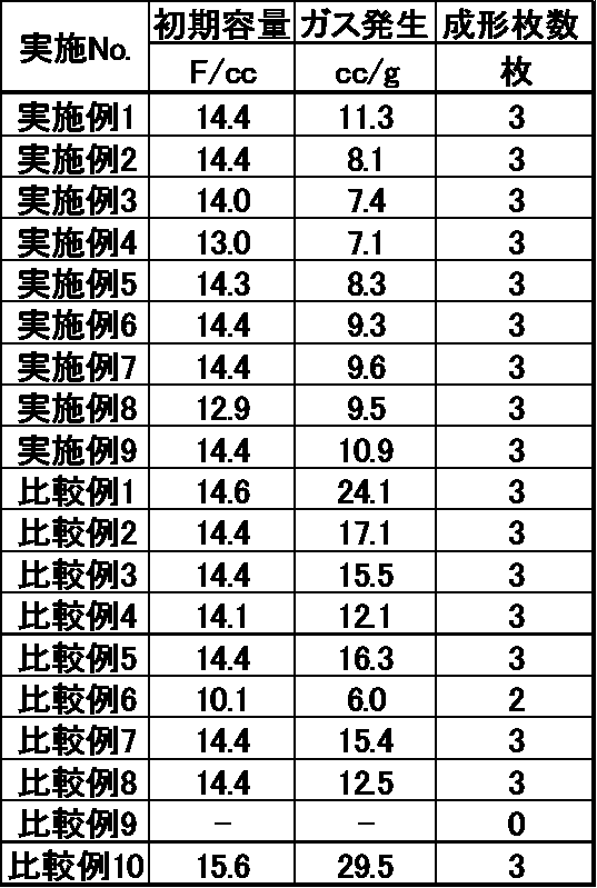
実施例1~9で得られた炭素質材料は優れた成形性を有しており、該炭素質材料から作製した電気二重層キャパシタ用電極を備える電気二重層キャパシタは、ガス発生量が少なく、高い初期容量を有することが分かる。一方、比較例9で得られた炭素質材料は、成形性に劣っており、比較例6で得られた炭素質材料から作製した電極を備える電気二重層キャパシタは初期容量が低く、また、それ以外の比較例で得られた炭素質材料から作製した電極を備える電気二重層キャパシタは、ガス発生量が多いことが分かる。
1 電極組成物
2 導電性接着剤
3 エッチングアルミニウム箔
4 タブ
5 シーラント
6 分極性電極
7 袋状外装シート
8 電気二重層キャパシタ
(1) 熱圧着された一辺
(2) タブが接する一辺
(3) 袋状外装シートの残る一辺
2 導電性接着剤
3 エッチングアルミニウム箔
4 タブ
5 シーラント
6 分極性電極
7 袋状外装シート
8 電気二重層キャパシタ
(1) 熱圧着された一辺
(2) タブが接する一辺
(3) 袋状外装シートの残る一辺
Claims (9)
- ケイ素元素の含有量が200ppm未満であり、粉体導電率が10.0~22.0S/cmであり、全表面官能基量が0.22~0.36meq/gであり、BJH法により測定される細孔径4nm以上の細孔容積が0.10~0.20cm3/gである、炭素質材料。
- BET比表面積が1400~2200m2/gである、請求項1に記載の炭素質材料。
- アルカリ金属の含有量が40ppm未満である、請求項1または2に記載の炭素質材料。
- 植物由来の炭素前駆体に基づく、請求項1~3のいずれかに記載の炭素質材料。
- 前記植物由来の炭素前駆体がヤシ殻である、請求項1~4のいずれかに記載の炭素質材料。
- 請求項1~5のいずれかに記載の炭素質材料を含む、電気二重層キャパシタ用電極活物質。
- 請求項6に記載の電気二重層キャパシタ用電極活物質を含む、電気二重層キャパシタ用電極。
- 請求項7に記載の電気二重層キャパシタ用電極を備える、電気二重層キャパシタ。
- 炭素前駆体を炭化後、賦活して得られる活性炭を、65℃以上のアルカリ性溶液中で洗浄する工程、および
前記アルカリ洗浄後の活性炭を酸洗浄後、不活性ガス雰囲気下、1000~1300℃で熱処理し、粉砕する工程、
を含む、請求項1~5のいずれかに記載の炭素質材料の製造方法。
Priority Applications (6)
| Application Number | Priority Date | Filing Date | Title |
|---|---|---|---|
| EP20908001.9A EP4084026A4 (en) | 2019-12-25 | 2020-12-15 | CARBON MATERIAL, PRODUCTION METHOD THEREFOR, ACTIVE MATERIAL OF ELECTRODE FOR DOUBLE LAYER ELECTRIC CAPACITORS, ELECTRODE FOR DOUBLE LAYER ELECTRIC CAPACITOR AND ELECTRIC DOUBLE LAYER CAPACITOR |
| KR1020227010523A KR20220121774A (ko) | 2019-12-25 | 2020-12-15 | 탄소질 재료, 그 제조 방법, 전기 이중층 커패시터용 전극 활물질, 전기 이중층 커패시터용 전극 및 전기 이중층 커패시터 |
| CN202080089886.5A CN114829301A (zh) | 2019-12-25 | 2020-12-15 | 碳质材料、其制造方法、电双层电容器用电极活性物质、电双层电容器用电极和电双层电容器 |
| JP2021567305A JPWO2021131907A1 (ja) | 2019-12-25 | 2020-12-15 | |
| US17/788,365 US20230043072A1 (en) | 2019-12-25 | 2020-12-15 | Carbonaceous material, method for producing same, electrode active material for electric double layer capacitors, electrode for electric double layer capacitors, and electric double layer capacitor |
| JP2025063136A JP2025100629A (ja) | 2019-12-25 | 2025-04-07 | 炭素質材料、その製造方法、電気二重層キャパシタ用電極活物質、電気二重層キャパシタ用電極および電気二重層キャパシタ |
Applications Claiming Priority (2)
| Application Number | Priority Date | Filing Date | Title |
|---|---|---|---|
| JP2019-234855 | 2019-12-25 | ||
| JP2019234855 | 2019-12-25 |
Publications (1)
| Publication Number | Publication Date |
|---|---|
| WO2021131907A1 true WO2021131907A1 (ja) | 2021-07-01 |
Family
ID=76576081
Family Applications (1)
| Application Number | Title | Priority Date | Filing Date |
|---|---|---|---|
| PCT/JP2020/046770 Ceased WO2021131907A1 (ja) | 2019-12-25 | 2020-12-15 | 炭素質材料、その製造方法、電気二重層キャパシタ用電極活物質、電気二重層キャパシタ用電極および電気二重層キャパシタ |
Country Status (6)
| Country | Link |
|---|---|
| US (1) | US20230043072A1 (ja) |
| EP (1) | EP4084026A4 (ja) |
| JP (2) | JPWO2021131907A1 (ja) |
| KR (1) | KR20220121774A (ja) |
| CN (1) | CN114829301A (ja) |
| WO (1) | WO2021131907A1 (ja) |
Cited By (1)
| Publication number | Priority date | Publication date | Assignee | Title |
|---|---|---|---|---|
| WO2026083826A1 (ja) * | 2024-10-18 | 2026-04-23 | パナソニックホールディングス株式会社 | ポーラスカーボン、電極材料、触媒担体、キャパシタ、燃料電池、二次電池、およびポーラスカーボンの製造方法 |
Families Citing this family (1)
| Publication number | Priority date | Publication date | Assignee | Title |
|---|---|---|---|---|
| CN117776155A (zh) * | 2024-01-02 | 2024-03-29 | 福建龙净储能科技有限公司 | 一种煤基硬碳负极材料及其制备方法和应用 |
Citations (7)
| Publication number | Priority date | Publication date | Assignee | Title |
|---|---|---|---|---|
| US20060223701A1 (en) * | 2001-02-26 | 2006-10-05 | Adrianov Michail N | Modified activated carbon for capacitor electrodes and method of fabrication thereof |
| JP2008021966A (ja) * | 2006-06-14 | 2008-01-31 | Calgon Mitsubishi Chemical Corp | 電気二重層キャパシタ用リン化合物複合活性炭及びその製造方法 |
| WO2008053919A1 (en) * | 2006-11-02 | 2008-05-08 | Kuraray Chemical Co., Ltd | Activated carbon and process for production thereof, nonaqueous type polarizable electrodes and electric double-layer capacitors |
| JP2008273816A (ja) * | 2007-04-04 | 2008-11-13 | Sony Corp | 多孔質炭素材料及びその製造方法、並びに、吸着剤、マスク、吸着シート及び担持体 |
| JP5770550B2 (ja) | 2011-07-20 | 2015-08-26 | 関西熱化学株式会社 | 活性炭及びその製造方法 |
| CN108439402A (zh) * | 2018-06-06 | 2018-08-24 | 山东大学 | 一种超级电容器用姜秸秆基活性炭及其制备方法 |
| WO2018207769A1 (ja) | 2017-05-10 | 2018-11-15 | 株式会社クラレ | 改質活性炭およびその製造方法 |
Family Cites Families (7)
| Publication number | Priority date | Publication date | Assignee | Title |
|---|---|---|---|---|
| JP6324726B2 (ja) * | 2010-12-28 | 2018-05-16 | ビーエーエスエフ ソシエタス・ヨーロピアBasf Se | 電気化学特性が向上した炭素材料 |
| US20120177923A1 (en) * | 2012-03-20 | 2012-07-12 | Haycarb PLC | Low ash activated carbon and methods of making same |
| EP2889937B1 (en) * | 2012-08-23 | 2018-10-03 | Mitsubishi Chemical Corporation | Carbon material for non-aqueous electrolyte secondary battery, negative electrode for non-aqueous electrolyte secondary battery, non-aqueous electrolyte secondary battery, and manufacturing method for carbon material for non-aqueous electrolyte secondary battery |
| US9318273B2 (en) * | 2013-07-26 | 2016-04-19 | Corning Incorporated | High voltage EDLC electrodes containing CO2 activated coconut char |
| US20150329364A1 (en) * | 2014-05-13 | 2015-11-19 | Georgia-Pacific Chemicals Llc | Activated carbon products and methods for making and using same |
| KR102130931B1 (ko) * | 2016-11-15 | 2020-07-08 | 주식회사 쿠라레 | 전기 이중층 캐패시터용 탄소질 재료 및 그 제조 방법 |
| WO2019092128A1 (en) * | 2017-11-10 | 2019-05-16 | Climeworks Ag | Materials for the direct capture of carbon dioxide from atmospheric air |
-
2020
- 2020-12-15 WO PCT/JP2020/046770 patent/WO2021131907A1/ja not_active Ceased
- 2020-12-15 EP EP20908001.9A patent/EP4084026A4/en active Pending
- 2020-12-15 CN CN202080089886.5A patent/CN114829301A/zh active Pending
- 2020-12-15 US US17/788,365 patent/US20230043072A1/en active Pending
- 2020-12-15 KR KR1020227010523A patent/KR20220121774A/ko active Pending
- 2020-12-15 JP JP2021567305A patent/JPWO2021131907A1/ja active Pending
-
2025
- 2025-04-07 JP JP2025063136A patent/JP2025100629A/ja active Pending
Patent Citations (7)
| Publication number | Priority date | Publication date | Assignee | Title |
|---|---|---|---|---|
| US20060223701A1 (en) * | 2001-02-26 | 2006-10-05 | Adrianov Michail N | Modified activated carbon for capacitor electrodes and method of fabrication thereof |
| JP2008021966A (ja) * | 2006-06-14 | 2008-01-31 | Calgon Mitsubishi Chemical Corp | 電気二重層キャパシタ用リン化合物複合活性炭及びその製造方法 |
| WO2008053919A1 (en) * | 2006-11-02 | 2008-05-08 | Kuraray Chemical Co., Ltd | Activated carbon and process for production thereof, nonaqueous type polarizable electrodes and electric double-layer capacitors |
| JP2008273816A (ja) * | 2007-04-04 | 2008-11-13 | Sony Corp | 多孔質炭素材料及びその製造方法、並びに、吸着剤、マスク、吸着シート及び担持体 |
| JP5770550B2 (ja) | 2011-07-20 | 2015-08-26 | 関西熱化学株式会社 | 活性炭及びその製造方法 |
| WO2018207769A1 (ja) | 2017-05-10 | 2018-11-15 | 株式会社クラレ | 改質活性炭およびその製造方法 |
| CN108439402A (zh) * | 2018-06-06 | 2018-08-24 | 山东大学 | 一种超级电容器用姜秸秆基活性炭及其制备方法 |
Non-Patent Citations (3)
| Title |
|---|
| DIAZ, E. ET AL.: "An JGC Study of the Role of Washing Procedures on the Adsorption Properties of Activated Carbons", ADSORPTION SCIENCE & TECHNOLOGY, vol. 25, 2007, pages 99 - 111, XP055837951, DOI: 10.1260/026361707782398245 * |
| See also references of EP4084026A4 |
| YELETSKY, P. M . ET AL.: "Synthesis of mesoporous carbons by leaching out natural silica templates of rice husk", MICROPOROUS AND MESOPOROUS MATERIALS, vol. 121, 6 January 2009 (2009-01-06), pages 34 - 40, XP026029484, DOI: 10.1016/j.micromeso. 2008.12.02 5 * |
Cited By (1)
| Publication number | Priority date | Publication date | Assignee | Title |
|---|---|---|---|---|
| WO2026083826A1 (ja) * | 2024-10-18 | 2026-04-23 | パナソニックホールディングス株式会社 | ポーラスカーボン、電極材料、触媒担体、キャパシタ、燃料電池、二次電池、およびポーラスカーボンの製造方法 |
Also Published As
| Publication number | Publication date |
|---|---|
| CN114829301A (zh) | 2022-07-29 |
| EP4084026A1 (en) | 2022-11-02 |
| US20230043072A1 (en) | 2023-02-09 |
| JPWO2021131907A1 (ja) | 2021-07-01 |
| KR20220121774A (ko) | 2022-09-01 |
| EP4084026A4 (en) | 2024-02-21 |
| JP2025100629A (ja) | 2025-07-03 |
Similar Documents
| Publication | Publication Date | Title |
|---|---|---|
| KR102572395B1 (ko) | 개질 활성탄 및 그 제조 방법 | |
| JP6342601B1 (ja) | 電気二重層キャパシタ用炭素質材料およびその製造方法 | |
| CN102460620B (zh) | 双电层电容器电极用碳材料和碳材料的生产方法 | |
| JP7545418B2 (ja) | 炭素質材料およびその製造方法、電気二重層キャパシタ用電極材料 | |
| JP2025100629A (ja) | 炭素質材料、その製造方法、電気二重層キャパシタ用電極活物質、電気二重層キャパシタ用電極および電気二重層キャパシタ | |
| JP7349988B2 (ja) | 炭素質材料、その製造方法、電気化学デバイス用電極活物質、電気化学デバイス用電極および電気化学デバイス | |
| US20250125356A1 (en) | Carbonaceous material, method for producing same, electrode active material for electrochemical device, electrode for electrochemical device, and electrochemical device | |
| KR102765325B1 (ko) | 탄소질 재료, 그 제조 방법, 전기 화학 디바이스용 전극 활물질, 전기 화학 디바이스용 전극 및 전기 화학 디바이스 | |
| KR102958578B1 (ko) | 탄소질 재료, 그 제조 방법, 전기 화학 디바이스용 전극 활물질, 전기 화학 디바이스용 전극 및 전기 화학 디바이스 | |
| KR20260057693A (ko) | 탄소질 재료, 그 제조 방법, 전기 화학 디바이스용 전극 활물질, 전기 화학 디바이스용 전극 및 전기 화학 디바이스 |
Legal Events
| Date | Code | Title | Description |
|---|---|---|---|
| 121 | Ep: the epo has been informed by wipo that ep was designated in this application |
Ref document number: 20908001 Country of ref document: EP Kind code of ref document: A1 |
|
| ENP | Entry into the national phase |
Ref document number: 2021567305 Country of ref document: JP Kind code of ref document: A |
|
| NENP | Non-entry into the national phase |
Ref country code: DE |
|
| ENP | Entry into the national phase |
Ref document number: 2020908001 Country of ref document: EP Effective date: 20220725 |