WO2021132023A1 - 医用画像処理装置、医用画像処理方法及びプログラム - Google Patents
医用画像処理装置、医用画像処理方法及びプログラム Download PDFInfo
- Publication number
- WO2021132023A1 WO2021132023A1 PCT/JP2020/047179 JP2020047179W WO2021132023A1 WO 2021132023 A1 WO2021132023 A1 WO 2021132023A1 JP 2020047179 W JP2020047179 W JP 2020047179W WO 2021132023 A1 WO2021132023 A1 WO 2021132023A1
- Authority
- WO
- WIPO (PCT)
- Prior art keywords
- medical image
- specific scene
- recognition
- display
- processor
- Prior art date
- Legal status (The legal status is an assumption and is not a legal conclusion. Google has not performed a legal analysis and makes no representation as to the accuracy of the status listed.)
- Ceased
Links
Images










Classifications
-
- A—HUMAN NECESSITIES
- A61—MEDICAL OR VETERINARY SCIENCE; HYGIENE
- A61B—DIAGNOSIS; SURGERY; IDENTIFICATION
- A61B1/00—Instruments for performing medical examinations of the interior of cavities or tubes of the body by visual or photographical inspection, e.g. endoscopes; Illuminating arrangements therefor
- A61B1/00002—Operational features of endoscopes
- A61B1/00004—Operational features of endoscopes characterised by electronic signal processing
- A61B1/00009—Operational features of endoscopes characterised by electronic signal processing of image signals during a use of endoscope
- A61B1/000094—Operational features of endoscopes characterised by electronic signal processing of image signals during a use of endoscope extracting biological structures
-
- A—HUMAN NECESSITIES
- A61—MEDICAL OR VETERINARY SCIENCE; HYGIENE
- A61B—DIAGNOSIS; SURGERY; IDENTIFICATION
- A61B1/00—Instruments for performing medical examinations of the interior of cavities or tubes of the body by visual or photographical inspection, e.g. endoscopes; Illuminating arrangements therefor
- A61B1/00002—Operational features of endoscopes
- A61B1/00004—Operational features of endoscopes characterised by electronic signal processing
- A61B1/00009—Operational features of endoscopes characterised by electronic signal processing of image signals during a use of endoscope
- A61B1/000095—Operational features of endoscopes characterised by electronic signal processing of image signals during a use of endoscope for image enhancement
-
- A—HUMAN NECESSITIES
- A61—MEDICAL OR VETERINARY SCIENCE; HYGIENE
- A61B—DIAGNOSIS; SURGERY; IDENTIFICATION
- A61B1/00—Instruments for performing medical examinations of the interior of cavities or tubes of the body by visual or photographical inspection, e.g. endoscopes; Illuminating arrangements therefor
- A61B1/00002—Operational features of endoscopes
- A61B1/00004—Operational features of endoscopes characterised by electronic signal processing
- A61B1/00009—Operational features of endoscopes characterised by electronic signal processing of image signals during a use of endoscope
- A61B1/000096—Operational features of endoscopes characterised by electronic signal processing of image signals during a use of endoscope using artificial intelligence
-
- A—HUMAN NECESSITIES
- A61—MEDICAL OR VETERINARY SCIENCE; HYGIENE
- A61B—DIAGNOSIS; SURGERY; IDENTIFICATION
- A61B1/00—Instruments for performing medical examinations of the interior of cavities or tubes of the body by visual or photographical inspection, e.g. endoscopes; Illuminating arrangements therefor
- A61B1/00002—Operational features of endoscopes
- A61B1/00043—Operational features of endoscopes provided with output arrangements
- A61B1/00045—Display arrangement
- A61B1/0005—Display arrangement combining images e.g. side-by-side, superimposed or tiled
-
- G—PHYSICS
- G16—INFORMATION AND COMMUNICATION TECHNOLOGY [ICT] SPECIALLY ADAPTED FOR SPECIFIC APPLICATION FIELDS
- G16H—HEALTHCARE INFORMATICS, i.e. INFORMATION AND COMMUNICATION TECHNOLOGY [ICT] SPECIALLY ADAPTED FOR THE HANDLING OR PROCESSING OF MEDICAL OR HEALTHCARE DATA
- G16H30/00—ICT specially adapted for the handling or processing of medical images
- G16H30/20—ICT specially adapted for the handling or processing of medical images for handling medical images, e.g. DICOM, HL7 or PACS
-
- G—PHYSICS
- G16—INFORMATION AND COMMUNICATION TECHNOLOGY [ICT] SPECIALLY ADAPTED FOR SPECIFIC APPLICATION FIELDS
- G16H—HEALTHCARE INFORMATICS, i.e. INFORMATION AND COMMUNICATION TECHNOLOGY [ICT] SPECIALLY ADAPTED FOR THE HANDLING OR PROCESSING OF MEDICAL OR HEALTHCARE DATA
- G16H30/00—ICT specially adapted for the handling or processing of medical images
- G16H30/40—ICT specially adapted for the handling or processing of medical images for processing medical images, e.g. editing
-
- A—HUMAN NECESSITIES
- A61—MEDICAL OR VETERINARY SCIENCE; HYGIENE
- A61B—DIAGNOSIS; SURGERY; IDENTIFICATION
- A61B1/00—Instruments for performing medical examinations of the interior of cavities or tubes of the body by visual or photographical inspection, e.g. endoscopes; Illuminating arrangements therefor
- A61B1/04—Instruments for performing medical examinations of the interior of cavities or tubes of the body by visual or photographical inspection, e.g. endoscopes; Illuminating arrangements therefor combined with photographic or television appliances
- A61B1/043—Instruments for performing medical examinations of the interior of cavities or tubes of the body by visual or photographical inspection, e.g. endoscopes; Illuminating arrangements therefor combined with photographic or television appliances for fluorescence imaging
-
- A—HUMAN NECESSITIES
- A61—MEDICAL OR VETERINARY SCIENCE; HYGIENE
- A61B—DIAGNOSIS; SURGERY; IDENTIFICATION
- A61B1/00—Instruments for performing medical examinations of the interior of cavities or tubes of the body by visual or photographical inspection, e.g. endoscopes; Illuminating arrangements therefor
- A61B1/04—Instruments for performing medical examinations of the interior of cavities or tubes of the body by visual or photographical inspection, e.g. endoscopes; Illuminating arrangements therefor combined with photographic or television appliances
- A61B1/05—Instruments for performing medical examinations of the interior of cavities or tubes of the body by visual or photographical inspection, e.g. endoscopes; Illuminating arrangements therefor combined with photographic or television appliances characterised by the image sensor, e.g. camera, being in the distal end portion
-
- A—HUMAN NECESSITIES
- A61—MEDICAL OR VETERINARY SCIENCE; HYGIENE
- A61B—DIAGNOSIS; SURGERY; IDENTIFICATION
- A61B1/00—Instruments for performing medical examinations of the interior of cavities or tubes of the body by visual or photographical inspection, e.g. endoscopes; Illuminating arrangements therefor
- A61B1/06—Instruments for performing medical examinations of the interior of cavities or tubes of the body by visual or photographical inspection, e.g. endoscopes; Illuminating arrangements therefor with illuminating arrangements
- A61B1/0638—Instruments for performing medical examinations of the interior of cavities or tubes of the body by visual or photographical inspection, e.g. endoscopes; Illuminating arrangements therefor with illuminating arrangements providing two or more wavelengths
-
- A—HUMAN NECESSITIES
- A61—MEDICAL OR VETERINARY SCIENCE; HYGIENE
- A61B—DIAGNOSIS; SURGERY; IDENTIFICATION
- A61B1/00—Instruments for performing medical examinations of the interior of cavities or tubes of the body by visual or photographical inspection, e.g. endoscopes; Illuminating arrangements therefor
- A61B1/06—Instruments for performing medical examinations of the interior of cavities or tubes of the body by visual or photographical inspection, e.g. endoscopes; Illuminating arrangements therefor with illuminating arrangements
- A61B1/0661—Endoscope light sources
- A61B1/0669—Endoscope light sources at proximal end of an endoscope
-
- A—HUMAN NECESSITIES
- A61—MEDICAL OR VETERINARY SCIENCE; HYGIENE
- A61B—DIAGNOSIS; SURGERY; IDENTIFICATION
- A61B1/00—Instruments for performing medical examinations of the interior of cavities or tubes of the body by visual or photographical inspection, e.g. endoscopes; Illuminating arrangements therefor
- A61B1/06—Instruments for performing medical examinations of the interior of cavities or tubes of the body by visual or photographical inspection, e.g. endoscopes; Illuminating arrangements therefor with illuminating arrangements
- A61B1/07—Instruments for performing medical examinations of the interior of cavities or tubes of the body by visual or photographical inspection, e.g. endoscopes; Illuminating arrangements therefor with illuminating arrangements using light-conductive means, e.g. optical fibres
Definitions
- the present invention relates to a medical image processing apparatus, a medical image processing method and a program.
- Diagnosis and medical examination using the endoscopic device is performed by displaying the endoscopic image acquired by the endoscopic device on the monitor and observing the endoscopic image displayed on the monitor by the doctor.
- Patent Document 1 a technique for assisting a doctor's observation by image-processing an endoscopic image to estimate a lesion and superimposing a mark on the lesion and displaying it on a monitor.
- a recognizer made by deep learning may be used. Specifically, a specific scene has been observed by automatically recognizing a specific scene from an endoscopic image with a recognizer created by deep learning and presenting the recognized specific scene to a user (doctor, etc.). Notify that.
- the recognizer may recognize a specific scene even if a specific scene is momentarily shot when the endoscope scope is moved quickly, and in that case, the user recognizes the specific scene. Notification is made as completed.
- the user momentarily shoots a specific scene, the user does not observe the specific scene. In this way, there may be a discrepancy between the recognition of the specific scene by the recognizer and the actual observation by the user.
- the recognizer since the recognizer notifies the user that the specific scene has been observed, the user mistakenly recognizes the specific scene as observed by looking at the notification display even though the specific scene is not originally observed. There is a fear.
- the present invention has been made in view of such circumstances, and an object of the present invention is to provide a medical image processing apparatus, a medical image processing method, and a program capable of reducing the discrepancy between the recognition of the recognizer and the recognition of the user. That is.
- the medical image processing apparatus for achieving the above object is a medical image processing apparatus including a processor, and the processor sequentially acquires a plurality of medical images in chronological order, and the acquired medical image is used. Based on the image, the specific scene of the medical image is recognized, the recognition frequency of the recognized specific scene is acquired, and a notification display indicating the degree of recognition that changes in two or more stages according to the recognition frequency is displayed on the monitor. ..
- a notification display indicating the degree of recognition that changes in two or more stages according to the recognition frequency of the specific scene of the medical image is displayed on the monitor, so that the user is notified of the recognition frequency of the specific scene in the processor. It is possible to reduce the discrepancy between the observation of the user's specific scene and the recognition of the processor's specific scene.
- the processor displays a different color on the monitor as a notification display according to the recognition frequency.
- the processor displays a different line type on the monitor as a notification display according to the recognition frequency.
- the processor displays on the monitor a different degree of blurring as a notification display according to the recognition frequency.
- the processor acquires the recognition frequency based on the number of recognized medical images of the specific scene.
- the processor acquires the recognition frequency based on the number of chronologically continuous medical images of the recognized specific scene.
- the processor recognizes the specific scene by calculating the feature amount of the medical image of the specific scene and classifying the medical image based on the feature amount of the specific scene.
- the processor calculates the feature amount of the medical image of the specific scene and recognizes the specific scene based on the similarity between the feature amount and the medical image.
- the processor switches the notification display from the initial display to the first display and displays it on the monitor.
- the processor switches the notification display from the first display to the second display and displays it on the monitor.
- the processor displays a plurality of reference images having each of the plurality of specific scenes on the monitor to perform the first display and the second display.
- the processor displays a model image including a portion corresponding to a plurality of specific scenes on the monitor, and makes the recognized specific scene correspond to the model image to perform the first display and the second display.
- the processor associates the position where the specific scene is recognized with the position on the model image, superimposes the notification display on the model image, and displays it on the monitor.
- the processor displays an initial display different from the notification display on the monitor when the specific scene has not been recognized yet.
- the medical image processing method includes a medical image acquisition step of sequentially acquiring a plurality of medical images in chronological order, and a specific scene recognition that recognizes a specific scene of the medical image based on the acquired medical image.
- a display control that displays on the monitor a notification display indicating the degree of recognition that changes in two or more stages according to the step, the frequency acquisition step of acquiring the recognition frequency of the specific scene recognized by the specific scene recognition step, and the recognition frequency.
- a program includes a medical image acquisition step of sequentially acquiring a plurality of medical images in chronological order, a specific scene recognition step of recognizing a specific scene of a medical image based on the acquired medical image, and a specific scene recognition step.
- a frequency acquisition step for acquiring the recognition frequency of a specific scene recognized by the specific scene recognition step, a display control step for displaying a notification display indicating the degree of recognition that changes in two or more stages according to the recognition frequency on the monitor, and a display control step.
- FIG. 1 is an external view of the endoscope system.
- FIG. 2 is a block diagram showing a main configuration of an endoscope system.
- FIG. 3 is a functional block diagram of the medical image processing apparatus in the image processing unit.
- FIG. 4 is a diagram showing the configuration of CNN.
- FIG. 5 is a schematic view showing a configuration example of the intermediate layer.
- FIG. 6 is a flowchart showing a medical image processing method.
- FIG. 7 is a flow chart for acquiring the recognition frequency.
- FIG. 8 is a diagram showing an example of a notification display.
- FIG. 9 is a flow chart of a medical image processing method.
- FIG. 10 is a flow chart for acquiring the recognition frequency.
- FIG. 11 is a diagram showing a specific example of the first modification 1.
- FIG. 1 is an external view of the endoscope system.
- FIG. 2 is a block diagram showing a main configuration of an endoscope system.
- FIG. 3 is a functional block diagram of the medical
- FIG. 12 is a diagram showing a specific example of the second modification 1.
- FIG. 13 is a diagram showing a specific example of the third modification 1.
- FIG. 14 is a diagram showing a specific example of the fourth modification 1.
- FIG. 15 is a diagram showing a specific example of the fifth modification 1.
- FIG. 16 is a diagram showing a first modification 2.
- FIG. 17 is a diagram showing a second modification 2.
- FIG. 18 is a diagram showing a case where display is performed on two monitors.
- FIG. 1 is an external view of the endoscope system 10
- FIG. 2 is a block diagram showing a main configuration of the endoscope system 10.
- the endoscope system 10 includes an endoscope scope 100, an endoscope processor device 200, a light source device 300, and a monitor 400.
- the endoscope processor device 200 is equipped with the medical image processing device of the present invention.
- the endoscope scope 100 includes a hand operation unit 102 and an insertion unit 104 connected to the hand operation unit 102.
- the operator grips and operates the hand operation unit 102, inserts the insertion unit 104 into the body of the subject (living body), and observes it.
- the hand operation unit 102 is provided with an air supply / water supply button 141, a suction button 142, a function button 143 to which various functions can be assigned, and a shooting button 144 for receiving a shooting instruction operation (still image, moving image). ..
- the insertion portion 104 is composed of a soft portion 112, a curved portion 114, and a tip hard portion 116 in this order from the hand operation portion 102 side.
- the curved portion 114 is connected to the base end side of the hard tip portion 116, and the soft portion 112 is connected to the base end side of the curved portion 114.
- the hand operation unit 102 is connected to the base end side of the insertion unit 104. The user can bend the curved portion 114 and change the direction of the hard tip portion 116 up, down, left and right by operating the hand operating portion 102.
- the tip rigid portion 116 is provided with a photographing optical system 130, an illumination portion 123, a forceps opening 126, and the like (see FIGS. 1 and 2).
- white light and / or narrow band light (red narrow band light, green narrow band light, etc.) are transmitted from the illumination lenses 123A and 123B of the illumination unit 123.
- narrow band light red narrow band light, green narrow band light, etc.
- One or more of blue narrow band light and purple narrow band light can be irradiated.
- cleaning water is discharged from a water supply nozzle (not shown), and the photographing lens 132 of the photographing optical system 130 and the illumination lenses 123A and 123B can be washed.
- a conduit (not shown) communicates with the forceps opening 126 opened by the hard tip 116, and a treatment tool (not shown) for removing a tumor or the like is inserted into this conduit, and the patient moves back and forth as appropriate to the subject. You can take the necessary measures.
- a photographing lens 132 is arranged on the tip end surface 116A of the tip rigid portion 116.
- a CMOS (Complementary Metal-Oxide Semiconductor) type image sensor 134, a drive circuit 136, and an AFE 138 (AFE: Analog Front End) are arranged behind the photographing lens 132, and an image signal is output by these elements.
- the image pickup element 134 is a color image pickup element, and is composed of a plurality of light receiving elements arranged in a matrix (two-dimensional arrangement) in a specific pattern arrangement (Bayer arrangement, X-Trans (registered trademark) arrangement, honeycomb arrangement, etc.). It has a plurality of pixels.
- Each pixel of the image sensor 134 includes a microlens, a red (R), green (G), or blue (B) color filter and a photoelectric conversion unit (photodiode or the like).
- the photographing optical system 130 can also generate a color image from pixel signals of three colors of red, green, and blue, and generate an image from a pixel signal of any one or two colors of red, green, and blue. You can also do it.
- the image sensor 134 may be a CCD (Charge Coupled Device) type. Further, each pixel of the image sensor 134 may further include a purple color filter corresponding to a purple light source 310V and / or an infrared filter corresponding to an infrared light source.
- the optical image of the subject is imaged on the light receiving surface (imaging surface) of the image sensor 134 by the photographing lens 132, converted into an electric signal, and output to the endoscope processor device 200 via a signal cable (not shown) to form an image. Converted to a signal.
- the endoscope image (medical image) of the subject is displayed on the screen on the monitor 400 connected to the endoscope processor device 200.
- the illumination lenses 123A and 123B of the illumination portion 123 are provided adjacent to the photographing lens 132.
- the ejection ends of the light guide 170 which will be described later, are arranged behind the illumination lenses 123A and 123B, and the light guide 170 is inserted into the insertion portion 104, the hand operation portion 102, and the universal cable 106 to form the light guide 170.
- the incident end is arranged within the light guide connector 108.
- the user sequentially captures time-series endoscopic images in the living body by taking pictures at a predetermined frame rate while inserting or removing the endoscopic scope 100 having the above-described configuration into the living body which is the subject. can do.
- the light source device 300 includes a light source 310 for illumination, a diaphragm 330, a condenser lens 340, a light source control unit 350, and the like, and causes observation light to enter the light guide 170.
- the light source 310 includes a red light source 310R, a green light source 310G, a blue light source 310B, and a purple light source 310V that irradiate narrow band light of red, green, blue, and purple, respectively, and is narrow in red, green, blue, and purple. It can irradiate band light.
- the illuminance of the observation light by the light source 310 is controlled by the light source control unit 350, and the illuminance of the observation light can be changed (increased or decreased) and the illumination can be stopped as needed.
- the light source 310 can emit red, green, blue, and purple narrow-band light in any combination.
- narrow-band light of red, green, blue, and purple can be emitted at the same time to irradiate white light (normal light) as observation light, or one or two of them can be emitted to emit narrow-band light. It is also possible to irradiate light (special light).
- the light source 310 may further include an infrared light source that irradiates infrared light (an example of narrow band light).
- white light or narrow band light may be irradiated as observation light by a light source that irradiates white light and a filter that transmits white light and each narrow band light.
- the light source 310 may be a light source having a white band or a light source having a plurality of wavelength bands as the light having a white band, or a light source having a specific wavelength band narrower than the white wavelength band.
- the specific wavelength band may be a blue band or a green band in the visible region, or a red band in the visible region.
- a specific wavelength band is a visible blue band or green band, it includes a wavelength band of 390 nm or more and 450 nm or less, or 530 nm or more and 550 nm or less, and peaks in a wavelength band of 390 nm or more and 450 nm or less or 530 nm or more and 550 nm or less. It may have a wavelength.
- the light in the specific wavelength band includes the wavelength band of 585 nm or more and 615 nm or less, or 610 nm or more and 730 nm or less, and the light in the specific wavelength band is 585 nm or more and 615 nm or less or 610 nm or more. It may have a peak wavelength in the wavelength band of 730 nm or less.
- the specific wavelength band described above includes a wavelength band in which the oxidation hemoglobin and the reduced hemoglobin have different absorption coefficients and has a peak wavelength in the wavelength band in which the oxidation hemoglobin and the reduced hemoglobin have different absorption coefficients.
- the specific wavelength band includes a wavelength band of 400 ⁇ 10 nm, 440 ⁇ 10 nm, 470 ⁇ 10 nm, or 600 nm or more and 750 nm, and 400 ⁇ 10 nm, 440 ⁇ 10 nm, 470 ⁇ 10 nm, or 600 nm or more and 750 nm. It may have a peak wavelength in the following wavelength band.
- the light generated by the light source 310 may include a wavelength band of 790 nm or more and 820 nm or less, or 905 nm or more and 970 nm or less, and may have a peak wavelength in a wavelength band of 790 nm or more and 820 nm or less or 905 nm or more and 970 nm or less.
- the light source 310 may include a light source that irradiates excitation light having a peak of 390 nm or more and 470 nm or less. In this case, it is possible to acquire an endoscopic image having information on the fluorescence emitted by the fluorescent substance in the subject (living body).
- a dye for the fluorescence method fluorestin, acridine orange, etc. may be used.
- the light source type (laser light source, xenon light source, LED light source (LED: Light-Emitting Diode), etc.), wavelength, presence / absence of filter, etc. of the light source 310 are preferably configured according to the type of subject, the part, the purpose of observation, and the like.
- switching the wavelength for example, by rotating a disk-shaped filter (rotary color filter) arranged in front of the light source and provided with a filter that transmits or blocks light of a specific wavelength, the wavelength of the emitted light is switched. May be good.
- the image sensor used in carrying out the present invention is not limited to the color image sensor in which the color filter is arranged for each pixel like the image sensor 134, and may be a monochrome image sensor.
- the wavelength of the observation light can be sequentially switched to perform surface-sequential (color-sequential) imaging.
- the wavelength of the emitted observation light may be sequentially switched between (purple, blue, green, red), or a rotary color filter (red, green, blue, purple, etc.) is irradiated with broadband light (white light). You may switch the wavelength of the observation light emitted by.
- the wavelength of the observation light emitted by the rotary color filter (green, blue, purple, etc.) by irradiating one or a plurality of narrow band lights (green, blue, purple, etc.) may be switched.
- the narrow-band light may be infrared light having two or more wavelengths (first narrow-band light, second narrow-band light) having different wavelengths.
- the observation light emitted from the light source device 300 is transmitted to the illumination lenses 123A and 123B via the light guide 170, and the illumination lens
- the observation range is irradiated from 123A and 123B.
- the configuration of the endoscope processor device 200 will be described with reference to FIG.
- the endoscope processor device 200 inputs an image signal output from the endoscope scope 100 via the image input controller 202, performs necessary image processing in the image processing unit 204, and outputs the image signal via the video output unit 206. To do. As a result, the endoscopic image is displayed on the monitor 400.
- These processes are performed under the control of the CPU 210 (CPU: Central Processing Unit).
- the CPU 210 functions as a processor of a medical image processing device.
- the communication control unit 205 controls communication with respect to the acquisition of medical images, etc. between an in-hospital system (HIS: Hospital Information System), an in-hospital LAN (Local Area Network), and / or an external system or network (not shown). I do.
- the image processing unit 204 calculates the feature amount of the endoscopic image, processes to emphasize or reduce the components of a specific frequency band, and emphasizes or makes a specific target (area of interest, blood vessel of a desired depth, etc.) inconspicuous. Processing can be performed.
- the image processing unit 204 acquires special light having information in a specific wavelength band based on a normal light image obtained by irradiating light in a white band or light in a plurality of wavelength bands as light in the white band.
- An image acquisition unit (not shown) may be provided.
- the signal of a specific wavelength band is used for RGB (R: red, G: green, B: blue) or CMY (C: cyan, M: magenta, Y: yellow) color information included in a normal optical image. It can be obtained by the calculation based on.
- the image processing unit 204 includes a normal light image obtained by irradiating light in a white band or light in a plurality of wavelength bands as light in the white band, and a special light image obtained by irradiating light in a specific wavelength band.
- a feature amount image generation unit (not shown) that generates a feature amount image by an operation based on at least one of the above is provided, and a feature amount image as an endoscopic image may be acquired and displayed. The above-mentioned processing is performed under the control of the CPU 210.
- the image processing unit 204 has each function in the medical image processing device as described below.
- FIG. 3 is a functional block diagram of the medical image processing device in the image processing unit 204.
- the image processing unit 204 includes a medical image acquisition unit 220, a specific scene recognition unit 222, a frequency acquisition unit 224, and a display control unit 226.
- Various processors include, for example, a CPU (Central Processing Unit), which is a general-purpose processor that executes software (programs) to realize various functions.
- the various processors described above include programmable logic devices (PLCs) such as GPUs (Graphics Processing Units) and FPGAs (Field Programmable Gate Arrays), which are specialized processors for image processing, whose circuit configurations can be changed after manufacturing.
- PLCs programmable logic devices
- GPUs Graphics Processing Units
- FPGAs Field Programmable Gate Arrays
- PLD Programmable Logic Device
- the above-mentioned various processors also include a dedicated electric circuit, which is a processor having a circuit configuration specially designed for executing a specific process such as an ASIC (Application Specific Integrated Circuit).
- each part may be realized by one processor, or may be realized by a plurality of processors of the same type or different types (for example, a plurality of FPGAs, or a combination of a CPU and an FPGA, or a combination of a CPU and a GPU). Further, a plurality of functions may be realized by one processor. As an example of configuring a plurality of functions with one processor, first, as represented by a computer, one processor is configured by a combination of one or more CPUs and software, and this processor is used as a plurality of functions. There is a form to be realized.
- SoC System On Chip
- a processor that realizes the functions of the entire system with one IC (Integrated Circuit) chip
- various functions are configured by using one or more of the above-mentioned various processors as a hardware structure.
- the hardware structure of these various processors is, more specifically, an electric circuit (circuitry) in which circuit elements such as semiconductor elements are combined.
- These electric circuits may be electric circuits that realize the above-mentioned functions by using logical sum, logical product, logical denial, exclusive logical sum, and logical operations combining these.
- the processor or electric circuit executes software (program), it can be read by a computer of the software (for example, various processors and electric circuits constituting the image processing unit 204, and / or a combination thereof).
- the code is stored in a non-temporary recording medium such as ROM 211 (ROM: Read Only Memory), and the computer refers to the software.
- the software stored in the non-temporary recording medium is a program for executing the operation method of the medical image processing apparatus according to the present invention and data used for execution (data related to acquisition of medical images, notification conditions, and notification modes). Includes data used for identification, parameters used in the recognition unit, etc.).
- the code may be recorded on a non-temporary recording medium such as various optical magnetic recording devices or semiconductor memories instead of the ROM 211.
- a non-temporary recording medium such as various optical magnetic recording devices or semiconductor memories instead of the ROM 211.
- RAM212 RAM: Random Access Memory
- EEPROM Electrically Erasable and Programmable Read Only Memory
- the recording unit 207 may be used as the “non-temporary recording medium”.
- the ROM 211 (ROM: Read Only Memory) is a non-volatile storage element (non-temporary recording medium), and is a computer-readable code of a program that causes the CPU 210 and / or the image processing unit 204 to execute various image processing methods. Is remembered.
- the RAM 212 (RAM: Random Access Memory) is a storage element for temporary storage during various processes, and can also be used as a buffer for image acquisition.
- the voice processing unit 209 outputs voice and sound from the speaker 209A under the control of the CPU 210.
- the operation unit 208 can be configured by a device such as a keyboard and a mouse (not shown), and the user can specify the execution instruction of the process and the conditions necessary for the execution via the operation unit 208.
- the recording unit 207 records the acquired endoscopic image. In addition, programs and information for controlling the medical image processing apparatus are recorded.
- the recording unit 207 functions as a memory of the medical image processing device.
- the specific scene recognition unit 222 in the image processing unit 204 described above recognizes a specific scene configured by using a trained model such as a neural network (a model learned using an image set composed of images of a living body). It is composed of recognizers.
- the specific scenes are, for example, the esophagus, duodenum, cardia, pylorus, angular incisure, fundus, body of stomach, vestibule, small bowl, large bowl and the like.
- a CNN Convolutional Neural Network
- FIG. 4 is a diagram showing the configuration of CNN232 (neural network).
- the CNN 232 has an input layer 232A, an intermediate layer 232B, and an output layer 232C.
- the input layer 232A inputs the endoscopic image acquired by the medical image acquisition unit 220 and outputs the feature amount.
- the intermediate layer 232B includes the convolution layer 234 and the pooling layer 235, and the feature amount output by the input layer 232A is input to calculate other feature amounts.
- These layers have a structure in which a plurality of "nodes” are connected by “edges”, and the weighting coefficient applied to the input image is associated with the node and the edge and stored in a weighting coefficient storage unit (not shown). It is remembered. The value of the weighting factor changes as the learning progresses.
- the intermediate layer 232B calculates the feature amount by the convolution calculation and the pooling process.
- the convolution operation performed in the convolution layer 234 is a process of acquiring a feature map by a convolution operation using a filter, and plays a role of feature extraction such as edge extraction from an image. By the convolution operation using this filter, one channel (one sheet) of "feature map” is generated for one filter. The size of the "feature map”, if downscaled by convolution, becomes smaller as each layer is convolved.
- the pooling process performed in the pooling layer 235 is a process of reducing (or enlarging) the feature map output by the convolution operation to make a new feature map, so that the extracted features are not affected by translation or the like. Plays the role of giving robustness to.
- the intermediate layer 232B can be composed of one or a plurality of layers that perform these processes.
- the CNN232 may be configured without the pooling layer 235.
- CNN232 may include a fully bonded layer 236 as in the example shown in part (b) of FIG.
- the layer structure of CNN232 is not limited to the case where the convolution layer 234 and the pooling layer 235 are repeated one by one, and any one layer (for example, the convolution layer 234) may be continuously included.
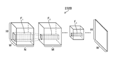
- FIG. 5 is a schematic view showing a configuration example of the intermediate layer 232B of the CNN 232 shown in FIG.
- the image set is composed of N images (N channels) having an image size of H in the vertical direction and W in the horizontal direction.
- the images constituting the image set are three-channel images of R (red), G (green), and B (blue). Since the image set of the filter F 1 to be convolved with this image set has N channels (N sheets), for example, in the case of a filter of size 5 (5 ⁇ 5), the filter size is 5 ⁇ 5 ⁇ N. Become.
- the filter F 2 used in the second convolution layer has a filter size of 3 ⁇ 3 ⁇ M, for example, in the case of a size 3 (3 ⁇ 3) filter.
- the second to nth convolution layers perform convolution operations using filters F 2 to F n.
- the size of the "feature map" in the nth convolution layer is smaller than the size of the "feature map” in the second convolution layer because it is downscaled by the convolution layer or pooling layer up to the previous stage. Is.
- low-order feature extraction (edge extraction, etc.) is performed in the convolution layer near the input side, and higher-order feature extraction (features related to the shape, structure, etc. of the recognition target) is performed as the intermediate layer 232B approaches the output side. Extraction) is performed.
- the intermediate layer 232B may include a layer for batch normalization in addition to the convolution layer 234 and the pooling layer 235.
- the batch normalization process is a process of normalizing the distribution of data in units of mini-batch when learning, and plays a role of advancing learning quickly, reducing dependence on initial values, suppressing overfitting, and the like.
- the output layer 232C outputs the feature amount calculated by the intermediate layer 232B in a format suitable for specific scene recognition.
- the output layer 232C may include a fully connected layer.
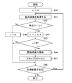
- FIG. 6 is a flowchart showing a medical image processing method. Each step will be described below with reference to FIG.
- the medical image acquisition unit 220 sequentially acquires a plurality of medical images in chronological order (step S10).
- the medical image acquisition unit 220 may acquire a medical image of the body cavity taken by the endoscope scope 100, or may acquire a medical image of the body cavity recorded by the recording unit 207.
- the specific scene recognition unit 222 recognizes a specific scene in the acquired medical image.
- the specific scene recognition unit 222 receives the medical image, inputs the medical image to the above-mentioned CNN, and extracts the feature amount from the medical image step by step.
- the specific scene recognition unit 222 finally utilizes its features to classify (for example, esophagus, duodenum, cardia, pyorrhea, angular incisure, fundus, body of stomach, vestibule, small bowl, large bowl). , Other 11 class classifications) to recognize a specific scene.
- This recognition method can be found in the following documents (B. Zhou, A. Lapedriza, J. Xiao, A.
- Torralba and A. Oliva. Learning deep features for scene recognition using places database). .
- NIPS Neural Information Processing Systems
- the specific scene recognition unit 222 recognizes the specific scene by comparing the finally extracted feature amount with the feature amount previously stored in the recording unit 207 (for example, the feature amount of the duodenum) and calculating the similarity. You can also do it.
- FaceNet A Unified Embedding for Face Recognition and Clustering https://arxiv.org/abs/1503.03832)).
- step S11 When the specific scene cannot be recognized by the medical image received by the specific scene recognition unit 222 (in the case of No in step S11), the medical image acquisition unit 220 has the next medical image (in step S19). (In the case of Yes), the next medical image is acquired (step S10). On the other hand, when the specific scene recognition unit 222 can recognize the specific scene in the medical image (Yes in step S11), the process proceeds to the frequency acquisition step (step S12) for updating the recognition frequency record.
- the frequency acquisition unit 224 updates the recognition frequency record when the specific scene recognition unit 222 recognizes the specific scene in the medical image (step S12). For example, when the duodenum, which is a specific scene, is recognized by the specific scene recognition unit 222, the recognition frequency of the duodenum is updated from 0 to 1. Various modes can be considered for updating the recognition frequency, and may be updated from 0 to 64, for example. The update of the recognition frequency will be described in detail later.
- the recognition frequency is equal to or higher than the first threshold value (in the case of Yes in step S13)
- the initial display is displayed on the monitor 400
- the first display is one of the notification displays. If the display of is not yet displayed on the monitor 400 (in the case of No in step S14), the initial display is changed to the first display (step S15).
- the display control unit 226 is a case where the recognition frequency is equal to or higher than the first threshold value (in the case of Yes in step S13) and the first display is already displayed on the monitor 400 on the monitor 400 (step S13).
- the recognition frequency is equal to or higher than the second threshold value (in the case of Yes in step S16)
- the initial display is changed to the second display.
- the first threshold value and the second threshold value are appropriately set by the user. In this way, the user recognizes the initial display, the first screen, or the second screen by displaying the initial display, the first screen, or the second screen on the monitor 400 by gradually changing the recognition frequency of the specific scene of the specific scene recognition unit 222. You can know the frequency.
- the recognition frequency is less than the first threshold value (when No in step S13), the recognition frequency is less than the second threshold value (when No in step S16), or the second display is already displayed on the monitor 400. If so (in the case of Yes in step S17), if there is a next medical image, the medical image acquisition unit 220 acquires the next medical image (step S10).
- FIG. 7 is a flow chart for acquiring the recognition frequency.
- FIG. 7 describes a case where the recognition frequency is updated according to the number of images in which a specific scene (for example, a pylorus) is recognized in the endoscopic image.
- n is the number of images recognizing a specific scene
- N is the frequency update threshold value, which is appropriately set by the user.
- the medical image acquisition unit 220 receives the medical image (step S21).
- the specific scene recognition unit 222 recognizes the specific scene in the medical image (Yes in step S22)
- the number of images n that recognize the specific scene is updated to n + 1 (step S23).
- the medical image acquisition unit 220 acquires the next medical image.
- the specific scene recognized by the specific scene recognition unit 222 may be one place or a plurality of places.
- a frequency threshold value is set for each specific scene, and the recognition frequency is updated for each specific scene.
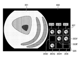
- FIG. 8 is a diagram showing an example of notification display on the monitor 400 performed by the display control unit 226.
- the endoscopic image (medical image) 301 captured in real time is displayed in the main display area of the monitor 400. Further, in the sub display area of the monitor 400, the notification display 303 composed of the reference image is displayed.
- the notification display 303 is composed of reference images (303A to 303I) of specific scenes 1 to 9.
- the notification display is switched and displayed on the monitor 400 according to the recognition frequency of the specific scene of the medical image, so that the user can specify the medical image in the medical image processing device (specific scene recognition unit 222). You can know the recognition frequency of the scene. Therefore, this embodiment can reduce the discrepancy between the recognition of the medical image processing device (specific scene recognition unit 222) and the recognition of the user.
- FIG. 9 is a flow chart of the medical image processing method in this example.
- the value of m in FIG. 9 indicates a screen number in the notification display.
- a threshold value is set corresponding to each notification display. Therefore, the th-th display is displayed when the recognition frequency is equal to or higher than the m-th threshold value.
- step S32 When the specific scene recognition unit 222 cannot recognize the specific scene (No in step S32), when the display is changed to the mth display (step S36), and when there is the next medical image (step). (In the case of Yes in S38), the medical image acquisition unit 220 acquires a medical image.
- the change is not limited to the first display and the change to the second display, but the change to the third display or higher is performed. As a result, the user can more accurately grasp the recognition frequency of a specific scene in the medical image processing device.
- n is the number of images recognizing a specific scene
- N is the frequency update threshold value, which is appropriately set by the user.
- FIG. 10 is a flow chart of acquisition of the recognition frequency by the frequency acquisition unit 224 of this example.
- the medical image acquisition unit 220 continuously acquires medical images in chronological order (step S41).
- the specific scene recognition unit 222 recognizes the specific scene in the medical image (Yes in step S42)
- the number of images n that recognize the specific scene is updated to n + 1 (step S44).
- step S45 When the number n of images recognizing the updated specific scene is equal to or greater than the frequency threshold value N (Yes in step S45), the recognition frequency is updated (step S46). After that, the display control step (step S13 to step S18: step S47) described with reference to FIG. 7 is performed. After that, if there is a next medical image (in the case of Yes in step S48), the process proceeds to the next endoscopic image processing.
- the recognition frequency is updated. Therefore, it is possible to output the recognition result of the specific scene recognition unit 222 by accurately reflecting what the user is observing.
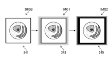
- IMGB is an initial display
- IMG1 is a first display that can be switched from the initial display
- IMG2 is a second display that can be switched from the first display.
- the color of the border changes according to the recognition frequency.
- the border 311 is black, in IMG1, the border 313 is white, and in IMG2, the border 315 is red.
- the user who sees the notification display of this example can grasp the recognition frequency of the specific scene recognition unit 222 from the color of the frame line.
- the type of border changes according to the recognition frequency.
- the frame line 321 is a fine dotted line
- the frame line 323 is a rougher dotted line than the frame line 321
- the frame line 325 is a solid line.
- the background color of the reference image changes according to the recognition frequency.
- the background 331 is white, in IMG1, the background 333 is gray, and in IMG2, the background 335 is black.
- the user who sees the notification display of this example can grasp the recognition frequency of the specific scene recognition unit 222 from the background color.
- the periphery 341 of the reference image is white
- the periphery 343 of the reference image is pink
- the periphery 345 of the reference image is red.
- the reference image is not displayed and the plain image 351 is displayed, in the IMG1 the unclear (blurred) reference image 353 is displayed, and in the IMG2 the clear reference image 355 is displayed.
- the user who sees the notification display of this example can grasp the recognition frequency of the specific scene recognition unit 222 based on the sharpness (blurring degree) of the reference image.
- FIG. 16 is a diagram showing the first modification 2.
- the model image 361 includes a portion corresponding to a plurality of specific scenes. Then, when each specific scene is recognized, a band display in which the color is changed according to the recognition frequency is performed as a notification display.
- the band display 363A which is the first display for the specific scene A
- the band display 363D which is the first display for the specific scene D
- the band display 363B which is the second display for the specific scene B
- the band display 363C which is the second display for the specific scene C
- the band display 363E which is the second display for the specific scene E
- the band displays 363A and 363D which are the first displays, are displayed in the same color
- the band displays 363B, 363C, and 363E which are the second displays, are displayed in the same color. In this way, the user who sees the notification display of this example can grasp the recognition frequency of the specific scene recognition unit 222 from the color of the band display superimposed on the model image.
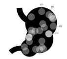
- FIG. 17 is a diagram showing a second modification 2.
- the model image 371 includes parts corresponding to a plurality of specific scenes.
- the recognition mark 373 is displayed as a notification display at a position corresponding to the recognized specific scene.
- the recognition marks 373 are displayed with overlap depending on the position of the specific scene, and the color of the overlapped recognition marks changes according to the degree of overlap.
- the recognition mark 373 is displayed so as to become brighter each time it overlaps. In this way, the user who has seen the notification display of this example can grasp the recognition frequency of the specific scene recognition unit 222 by displaying the recognition mark 373 which is displayed on the model image 371 and whose color changes each time it overlaps.
- ⁇ Modification example of monitor display> Next, a modified example of the monitor display will be described. In this example, the display is performed on two first monitors and a second monitor.
- FIG. 18 is a diagram showing a case where display is performed on two monitors (first monitor and second monitor).
- the medical image 301 acquired in real time is displayed on the first monitor 400A.
- the notification display 303 described with reference to FIG. 8 is performed. By performing the notification display 303 using the two monitors in this way, it is possible to perform a display with improved visibility.
Landscapes
- Health & Medical Sciences (AREA)
- Life Sciences & Earth Sciences (AREA)
- Engineering & Computer Science (AREA)
- Medical Informatics (AREA)
- Surgery (AREA)
- Radiology & Medical Imaging (AREA)
- Public Health (AREA)
- General Health & Medical Sciences (AREA)
- Nuclear Medicine, Radiotherapy & Molecular Imaging (AREA)
- Heart & Thoracic Surgery (AREA)
- Physics & Mathematics (AREA)
- Biomedical Technology (AREA)
- Optics & Photonics (AREA)
- Biophysics (AREA)
- Molecular Biology (AREA)
- Animal Behavior & Ethology (AREA)
- Pathology (AREA)
- Veterinary Medicine (AREA)
- Epidemiology (AREA)
- Primary Health Care (AREA)
- Signal Processing (AREA)
- Artificial Intelligence (AREA)
- Evolutionary Computation (AREA)
- Endoscopes (AREA)
Abstract
Description
図1は、内視鏡システム10の外観図であり、図2は内視鏡システム10の要部構成を示すブロック図である。図1、2に示すように、内視鏡システム10は、内視鏡スコープ100、内視鏡プロセッサ装置200、光源装置300、及びモニタ400から構成される。なお、内視鏡プロセッサ装置200は、本発明の医用画像処理装置を搭載する。
内視鏡スコープ100は、手元操作部102と、この手元操作部102に連設される挿入部104とを備える。術者(ユーザ)は手元操作部102を把持して操作し、挿入部104を被検体(生体)の体内に挿入して観察する。また、手元操作部102には送気送水ボタン141、吸引ボタン142、及び各種の機能を割り付けられる機能ボタン143、及び撮影指示操作(静止画像、動画像)を受け付ける撮影ボタン144が設けられている。挿入部104は、手元操作部102側から順に、軟性部112、湾曲部114、先端硬質部116で構成されている。すなわち、先端硬質部116の基端側に湾曲部114が接続され、湾曲部114の基端側に軟性部112が接続される。挿入部104の基端側に手元操作部102が接続される。ユーザは、手元操作部102を操作することにより湾曲部114を湾曲させて先端硬質部116の向きを上下左右に変えることができる。先端硬質部116には、撮影光学系130、照明部123、鉗子口126等が設けられる(図1、2参照)。
図2に示すように、光源装置300は、照明用の光源310、絞り330、集光レンズ340、及び光源制御部350等から構成されており、観察光をライトガイド170に入射させる。光源310は、それぞれ赤色、緑色、青色、紫色の狭帯域光を照射する赤色光源310R、緑色光源310G、青色光源310B、及び紫色光源310Vを備えており、赤色、緑色、青色、及び紫色の狭帯域光を照射することができる。光源310による観察光の照度は光源制御部350により制御され、必要に応じて観察光の照度を変更する(上げる、または下げる)こと、及び照明を停止することができる。
光源310は白色帯域の光、または白色帯域の光として複数の波長帯域の光を発生する光源でもよいし、白色の波長帯域よりも狭い特定の波長帯域の光を発生する光源でもよい。特定の波長帯域は、可視域の青色帯域もしくは緑色帯域、あるいは可視域の赤色帯域であってもよい。特定の波長帯域が可視域の青色帯域もしくは緑色帯域である場合、390nm以上450nm以下、または530nm以上550nm以下の波長帯域を含み、かつ、390nm以上450nm以下または530nm以上550nm以下の波長帯域内にピーク波長を有していてもよい。また、特定の波長帯域が可視域の赤色帯域である場合、585nm以上615nm以下、または610nm以上730nm以下、の波長帯域を含み、かつ、特定の波長帯域の光は、585nm以上615nm以下または610nm以上730nm以下の波長帯域内にピーク波長を有していてもよい。
図2に基づき内視鏡プロセッサ装置200の構成を説明する。内視鏡プロセッサ装置200は、内視鏡スコープ100から出力される画像信号を画像入力コントローラ202を介して入力し、画像処理部204で必要な画像処理を行ってビデオ出力部206を介して出力する。これによりモニタ400に内視鏡画像が表示される。これらの処理はCPU210(CPU:Central Processing Unit)の制御下で行われる。なおCPU210は、医用画像処理装置のプロセッサとして機能する。通信制御部205は、図示せぬ病院内システム(HIS:Hospital Information System)や病院内LAN(Local Area Network)、及び/または外部のシステムやネットワークとの間で医用画像の取得等についての通信制御を行う。
画像処理部204は、内視鏡画像の特徴量の算出、特定の周波数帯域の成分を強調または低減する処理、特定の対象(注目領域、所望の深さの血管等)を強調または目立たなくする処理を行うことができる。画像処理部204は、白色帯域の光、または白色帯域の光として複数の波長帯域の光を照射して得る通常光画像に基づいて特定の波長帯域の情報を有する特殊光画像を取得する特殊光画像取得部(不図示)を備えていてもよい。この場合、特定の波長帯域の信号は、通常光画像に含まれるRGB(R:赤、G:緑、B:青)あるいはCMY(C:シアン、M:マゼンタ、Y:イエロー)の色情報に基づく演算により得ることができる。また、画像処理部204は、白色帯域の光、または白色帯域の光として複数の波長帯域の光を照射して得る通常光画像と、特定の波長帯域の光を照射して得る特殊光画像との少なくとも一方に基づく演算によって特徴量画像を生成する特徴量画像生成部(不図示)を備え、内視鏡画像としての特徴量画像を取得及び表示してもよい。なお、上述した処理はCPU210の制御下で行われる。
上述した画像処理部204の各部の機能は、各種のプロセッサ(processor)及び記録媒体を用いて実現できる。各種のプロセッサには、例えばソフトウェア(プログラム)を実行して各種の機能を実現する汎用的なプロセッサであるCPU(Central Processing Unit)が含まれる。また、上述した各種のプロセッサには、画像処理に特化したプロセッサであるGPU(Graphics Processing Unit)、FPGA(Field Programmable Gate Array)などの製造後に回路構成を変更可能なプロセッサであるプログラマブルロジックデバイス(Programmable Logic Device:PLD)も含まれる。本発明のように画像の学習や認識を行う場合は、GPUを用いた構成が効果的である。さらに、ASIC(Application Specific Integrated Circuit)などの特定の処理を実行させるために専用に設計された回路構成を有するプロセッサである専用電気回路なども上述した各種のプロセッサに含まれる。
上述した画像処理部204における特定シーン認識部222は、ニューラルネットワーク等の学習済みモデル(生体を撮影した画像から構成される画像セットを用いて学習したモデル)を用いて構成する、特定シーンを認識する認識器で構成される。ここで特定シーンとは、例えば食道、十二指腸、噴門、幽門、胃角部、胃底部、胃体部、前庭部、小わん、大わん等である。以下、ニューラルネットワークとしてCNN(Convolutional Neural Network)を用いる場合の構成について説明する。
図4はCNN232(ニューラルネットワーク)の構成を示す図である。図4の(a)部分に示す例では、CNN232は、入力層232A、中間層232B、及び出力層232Cを有する。入力層232Aは医用画像取得部220が取得した内視鏡画像を入力して特徴量を出力する。中間層232Bは畳み込み層234及びプーリング層235を含み、入力層232Aが出力する特徴量を入力して他の特徴量を算出する。これらの層は複数の「ノード」が「エッジ」で結ばれた構造となっており、入力した画像に適用される重み係数が、ノード及びエッジに関連付けられて、図示せぬ重み係数記憶部に記憶されている。重み係数の値は、学習が進むにつれて変化していく。
中間層232Bは、畳み込み演算及びプーリング処理によって特徴量を算出する。畳み込み層234で行われる畳み込み演算はフィルタを使用した畳み込み演算により特徴マップを取得する処理であり、画像からのエッジ抽出等の特徴抽出の役割を担う。このフィルタを用いた畳み込み演算により、1つのフィルタに対して1チャンネル(1枚)の「特徴マップ」が生成される。「特徴マップ」のサイズは、畳み込みによりダウンスケーリングされる場合は、各層で畳み込みが行われるにつれて小さくなって行く。プーリング層235で行われるプーリング処理は畳み込み演算により出力された特徴マップを縮小(または拡大)して新たな特徴マップとする処理であり、抽出された特徴が、平行移動などによる影響を受けないようにロバスト性を与える役割を担う。中間層232Bは、これらの処理を行う1または複数の層により構成することができる。なお、CNN232はプーリング層235なしで構成されていてもよい。
次に、医用画像処理装置を使用した医用画像処理方法に関して説明する。なお、以下では、内視鏡システム10で取得された内視鏡画像を医用画像として処理する場合について説明するが、本発明の適用はこれに限定されるものではない。例えば、本発明では、他の内視鏡システム10で取得された内視鏡画像を、医用画像として医用画像処理装置で処理することもできる。
医用画像取得部220は複数の医用画像を時系列に順次取得する(ステップS10)。医用画像取得部220は、内視鏡スコープ100で撮影された体腔の医用画像を取得してもよいし、記録部207に記録された体腔の医用画像を取得してもよい。
特定シーン認識部222は、取得した医用画像において特定シーンを認識する。特定シーン認識部222は、医用画像を受信し、上述したCNNに医用画像を入力し段階的に医用画像から特徴量を抽出する。特定シーン認識部222は、最終的にその特徴量を利用して、クラス分類(例えば食道、十二指腸、噴門、幽門、胃角部、胃底部、胃体部、前庭部、小わん、大わん、その他の11クラス分類)を行うことで特定シーンを認識する。なお、この認識手法の詳しい説明は次の文献に記載されるものである(B. Zhou, A. Lapedriza, J. Xiao, A. Torralba, and A. Oliva. Learning deep features for scene recognition using places database. In Neural Information Processing Systems (NIPS), pages 487-495, 2014. 1, 4, 6, 8))。また、特定シーン認識部222は、最終的に抽出された特徴量を予め記録部207に保存された特徴量(例えば十二指腸の特徴量)と比較し類似度を算出することで特定シーンを認識することもできる。なお、この認識手法の詳しい説明は次の文献に記載されるものである(FaceNet: A Unified Embedding for Face Recognition and Clustering https://arxiv.org/abs/1503.03832))。
頻度取得部224は、特定シーン認識部222が医用画像において特定シーンを認識すると、認識頻度の記録を更新する(ステップS12)。例えば、特定シーンである十二指腸が特定シーン認識部222で認識された場合には、十二指腸の認識頻度を0から1に更新する。認識頻度の更新は、様々な態様が考えられ、例えば0から64等に更新してもよい。なお、認識頻度の更新に関しては、後で詳しく説明する。
表示制御部226は、認識頻度が第1の閾値以上であって(ステップS13のYesの場合)、初期表示がモニタ400に表示されており、報知表示の一つである第1の表示が未だモニタ400に表示されていない場合には(ステップS14のNoの場合)、初期表示を第1の表示に変化させる(ステップS15)。
次に、頻度取得部224により行われる頻度取得ステップに関して説明する。
次に、表示制御部226で行われるモニタ400への報知表示に関して説明する。
医用画像処理方法の各処理の変形例に関して説明する。上述した実施形態では、第1の表示と第2の表示とがモニタ400に表示されることを説明したが、本例では、第3の表示以上に変更して、報知表示をモニタ400に行う場合について説明する。
次に、認識頻度の更新の変形例に関して説明する。図7では特定シーンを認識できた医用画像の枚数に基づいて認識頻度の更新を行う例を説明したが、本例では、時系列的に連続する認識画像の枚数に基づいて認識頻度の更新を行う。なお、図中のnは特定シーンを認識した画像数であり、Nは頻度更新閾値でありユーザにより適宜設定される。
次に、報知表示の変形例1に関して説明する。本例では報知表示として、参照画像を使用した場合の様々な変形例を説明する。
次に、報知表示の変形例2に関して説明する。本例では、複数の特定シーンに対応する部位を含むモデル画像に報知表示を重畳させる。
次に、モニタ表示の変形例に関して説明する。本例では2つの第1のモニタ及び第2のモニタにおいて表示が行われる。
100 :内視鏡スコープ
102 :手元操作部
104 :挿入部
106 :ユニバーサルケーブル
108 :ライトガイドコネクタ
112 :軟性部
114 :湾曲部
116 :先端硬質部
116A :先端側端面
123 :照明部
123A :照明用レンズ
123B :照明用レンズ
126 :鉗子口
130 :撮影光学系
132 :撮影レンズ
134 :撮像素子
136 :駆動回路
141 :送気送水ボタン
142 :吸引ボタン
143 :機能ボタン
144 :撮影ボタン
170 :ライトガイド
200 :内視鏡プロセッサ装置
202 :画像入力コントローラ
204 :画像処理部
205 :通信制御部
206 :ビデオ出力部
207 :記録部
208 :操作部
209 :音声処理部
209A :スピーカ
210 :CPU
211 :ROM
212 :RAM
220 :医用画像取得部
222 :特定シーン認識部
224 :頻度取得部
226 :表示制御部
Claims (17)
- プロセッサを備える医用画像処理装置であって、
前記プロセッサは、
時系列に複数の医用画像を順次取得し、
取得した前記医用画像に基づいて、前記医用画像の特定シーンを認識し、
前記認識された前記特定シーンの認識頻度を取得し、
前記認識頻度に応じて、2段階以上に変化する認識の程度を示す報知表示をモニタに表示させる、
医用画像処理装置。 - 前記プロセッサは、前記認識頻度に応じて、前記報知表示として異なる色を、前記モニタに表示させる請求項1に記載の医用画像処理装置。
- 前記プロセッサは、前記認識頻度に応じて、前記報知表示として異なる線種を、前記モニタに表示させる請求項1又は2に記載の医用画像処理装置。
- 前記プロセッサは、前記認識頻度に応じて、前記報知表示として異なるボケ具合を、前記モニタに表示させる請求項1から3のいずれか1項に記載の医用画像処理装置。
- 前記プロセッサは、前記認識された前記特定シーンの前記医用画像の枚数に基づいて、前記認識頻度を取得する請求項1から4のいずれか1項に記載の医用画像処理装置。
- 前記プロセッサは、前記認識された前記特定シーンの時系列的に連続する前記医用画像の枚数に基づいて、前記認識頻度を取得する請求項1から4のいずれか1項に記載の医用画像処理装置。
- 前記プロセッサは、前記特定シーンの前記医用画像の特徴量を算出し、前記特定シーンの前記特徴量に基づいて前記医用画像をクラス分類することにより、前記特定シーンを認識する請求項1から6のいずれか1項に記載の医用画像処理装置。
- 前記プロセッサは、前記特定シーンの前記医用画像の特徴量を算出し、前記特徴量と前記医用画像との類似度に基づいて前記特定シーンを認識する請求項1から6のいずれか1項に記載の医用画像処理装置。
- 前記プロセッサは、前記認識頻度が第1の閾値以上の場合には、前記報知表示を初期表示から第1の表示に切り替えて、前記モニタに表示させる請求項1から6のいずれか1項に記載の医用画像処理装置。
- 前記プロセッサは、前記認識頻度が前記第1の閾値よりも大きい第2の閾値以上の場合には、前記報知表示を前記第1の表示から第2の表示に切り替えて、前記モニタに表示させる請求項9に記載の医用画像処理装置。
- 前記プロセッサは、前記モニタに、複数の前記特定シーンの各々を有する複数の参照画像を表示して、前記第1の表示及び前記第2の表示を行う請求項10に記載の医用画像処理装置。
- 前記プロセッサは、前記モニタに、複数の前記特定シーンに対応する部位を含むモデル画像を表示し、前記モデル画像に認識された前記特定シーンを対応させて、前記第1の表示及び前記第2の表示を行う請求項10に記載の医用画像処理装置。
- 前記プロセッサは、前記特定シーンが認識された位置と前記モデル画像上の位置とを対応させて、前記報知表示を前記モデル画像に重畳させて、前記モニタに表示させる請求項12に記載の医用画像処理装置。
- 前記プロセッサは、前記特定シーンの認識が未だなされていない場合には、前記報知表示とは異なる初期表示を、前記モニタに表示させる請求項1から13のいずれか1項に記載の医用画像処理装置。
- 時系列に複数の医用画像を順次取得する医用画像取得ステップと、
取得した前記医用画像に基づいて、前記医用画像の特定シーンを認識する特定シーン認識ステップと、
前記特定シーン認識ステップにより認識された前記特定シーンの認識頻度を取得する頻度取得ステップと、
前記認識頻度に応じて、2段階以上に変化する認識の程度を示す報知表示をモニタに表示させる表示制御ステップと、
を含む医用画像処理方法。 - 時系列に複数の医用画像を順次取得する医用画像取得ステップと、
取得した前記医用画像に基づいて、前記医用画像の特定シーンを認識する特定シーン認識ステップと、
前記特定シーン認識ステップにより認識された前記特定シーンの認識頻度を取得する頻度取得ステップと、
前記認識頻度に応じて、2段階以上に変化する認識の程度を示す報知表示をモニタに表示させる表示制御ステップと、
を含む医用画像処理方法をコンピュータに実行させるプログラム。 - 非一時的かつコンピュータ読取可能な記録媒体であって、請求項16に記載のプログラムが記録された記録媒体。
Priority Applications (4)
| Application Number | Priority Date | Filing Date | Title |
|---|---|---|---|
| JP2021567366A JP7648540B2 (ja) | 2019-12-26 | 2020-12-17 | 医用画像処理装置、作動方法、プログラム、及び記録媒体 |
| EP20905063.2A EP4082421A4 (en) | 2019-12-26 | 2020-12-17 | MEDICAL IMAGE PROCESSING DEVICE, MEDICAL IMAGE PROCESSING METHOD, AND PROGRAM |
| CN202080086065.6A CN114845624B (zh) | 2019-12-26 | 2020-12-17 | 医用图像处理装置、医用图像处理方法及程序 |
| US17/752,403 US12283367B2 (en) | 2019-12-26 | 2022-05-24 | Medical image processing apparatus, medical image processing method, and program |
Applications Claiming Priority (2)
| Application Number | Priority Date | Filing Date | Title |
|---|---|---|---|
| JP2019236673 | 2019-12-26 | ||
| JP2019-236673 | 2019-12-26 |
Related Child Applications (1)
| Application Number | Title | Priority Date | Filing Date |
|---|---|---|---|
| US17/752,403 Continuation US12283367B2 (en) | 2019-12-26 | 2022-05-24 | Medical image processing apparatus, medical image processing method, and program |
Publications (1)
| Publication Number | Publication Date |
|---|---|
| WO2021132023A1 true WO2021132023A1 (ja) | 2021-07-01 |
Family
ID=76574466
Family Applications (1)
| Application Number | Title | Priority Date | Filing Date |
|---|---|---|---|
| PCT/JP2020/047179 Ceased WO2021132023A1 (ja) | 2019-12-26 | 2020-12-17 | 医用画像処理装置、医用画像処理方法及びプログラム |
Country Status (5)
| Country | Link |
|---|---|
| US (1) | US12283367B2 (ja) |
| EP (1) | EP4082421A4 (ja) |
| JP (1) | JP7648540B2 (ja) |
| CN (1) | CN114845624B (ja) |
| WO (1) | WO2021132023A1 (ja) |
Cited By (1)
| Publication number | Priority date | Publication date | Assignee | Title |
|---|---|---|---|---|
| WO2023090091A1 (ja) * | 2021-11-19 | 2023-05-25 | 富士フイルム株式会社 | 画像処理装置及び内視鏡システム |
Families Citing this family (2)
| Publication number | Priority date | Publication date | Assignee | Title |
|---|---|---|---|---|
| WO2021149552A1 (ja) * | 2020-01-20 | 2021-07-29 | 富士フイルム株式会社 | 医療画像処理装置、医療画像処理装置の作動方法、及び内視鏡システム |
| CN117197867B (zh) * | 2023-08-29 | 2025-10-28 | 四川大学 | 一种调节人脸真伪检测算法的检测频率的方法 |
Citations (7)
| Publication number | Priority date | Publication date | Assignee | Title |
|---|---|---|---|---|
| JP2007319478A (ja) * | 2006-06-01 | 2007-12-13 | Fujifilm Corp | 医用画像表示装置及び方法、並びに内視鏡装置 |
| JP2008061704A (ja) * | 2006-09-05 | 2008-03-21 | Olympus Medical Systems Corp | 画像表示装置 |
| JP2011087793A (ja) | 2009-10-23 | 2011-05-06 | Hoya Corp | 電子内視鏡用プロセッサ |
| JP2012070938A (ja) * | 2010-09-28 | 2012-04-12 | Fujifilm Corp | 内視鏡画像記録装置、及び内視鏡画像記録支援方法、並びにプログラム |
| JP2015112429A (ja) * | 2013-12-13 | 2015-06-22 | オリンパスメディカルシステムズ株式会社 | 画像処理装置 |
| WO2019220848A1 (ja) * | 2018-05-17 | 2019-11-21 | 富士フイルム株式会社 | 内視鏡装置、内視鏡操作方法、及びプログラム |
| JP2019216948A (ja) * | 2018-06-19 | 2019-12-26 | オリンパス株式会社 | 画像処理装置、画像処理装置の作動方法、及び画像処理装置の作動プログラム |
Family Cites Families (4)
| Publication number | Priority date | Publication date | Assignee | Title |
|---|---|---|---|---|
| JP4624841B2 (ja) * | 2005-04-13 | 2011-02-02 | オリンパスメディカルシステムズ株式会社 | 画像処理装置および当該画像処理装置における画像処理方法 |
| US8900124B2 (en) | 2006-08-03 | 2014-12-02 | Olympus Medical Systems Corp. | Image display device |
| JP5226618B2 (ja) * | 2009-06-29 | 2013-07-03 | オリンパス株式会社 | 画像抽出装置、画像抽出方法および画像抽出プログラム |
| WO2018138828A1 (ja) * | 2017-01-26 | 2018-08-02 | オリンパス株式会社 | 画像処理装置、動作方法およびプログラム |
-
2020
- 2020-12-17 EP EP20905063.2A patent/EP4082421A4/en active Pending
- 2020-12-17 WO PCT/JP2020/047179 patent/WO2021132023A1/ja not_active Ceased
- 2020-12-17 CN CN202080086065.6A patent/CN114845624B/zh active Active
- 2020-12-17 JP JP2021567366A patent/JP7648540B2/ja active Active
-
2022
- 2022-05-24 US US17/752,403 patent/US12283367B2/en active Active
Patent Citations (7)
| Publication number | Priority date | Publication date | Assignee | Title |
|---|---|---|---|---|
| JP2007319478A (ja) * | 2006-06-01 | 2007-12-13 | Fujifilm Corp | 医用画像表示装置及び方法、並びに内視鏡装置 |
| JP2008061704A (ja) * | 2006-09-05 | 2008-03-21 | Olympus Medical Systems Corp | 画像表示装置 |
| JP2011087793A (ja) | 2009-10-23 | 2011-05-06 | Hoya Corp | 電子内視鏡用プロセッサ |
| JP2012070938A (ja) * | 2010-09-28 | 2012-04-12 | Fujifilm Corp | 内視鏡画像記録装置、及び内視鏡画像記録支援方法、並びにプログラム |
| JP2015112429A (ja) * | 2013-12-13 | 2015-06-22 | オリンパスメディカルシステムズ株式会社 | 画像処理装置 |
| WO2019220848A1 (ja) * | 2018-05-17 | 2019-11-21 | 富士フイルム株式会社 | 内視鏡装置、内視鏡操作方法、及びプログラム |
| JP2019216948A (ja) * | 2018-06-19 | 2019-12-26 | オリンパス株式会社 | 画像処理装置、画像処理装置の作動方法、及び画像処理装置の作動プログラム |
Non-Patent Citations (2)
| Title |
|---|
| B. ZHOUA. LAPEDRIZAJ. XIAOA. TORRALBAA. OLIVA: "Learning deep features for scene recognition using places database", NEURAL INFORMATION PROCESSING SYSTEMS (NIPS, 2014, pages 487 - 495 |
| See also references of EP4082421A4 |
Cited By (1)
| Publication number | Priority date | Publication date | Assignee | Title |
|---|---|---|---|---|
| WO2023090091A1 (ja) * | 2021-11-19 | 2023-05-25 | 富士フイルム株式会社 | 画像処理装置及び内視鏡システム |
Also Published As
| Publication number | Publication date |
|---|---|
| CN114845624A (zh) | 2022-08-02 |
| US20220285010A1 (en) | 2022-09-08 |
| EP4082421A1 (en) | 2022-11-02 |
| JPWO2021132023A1 (ja) | 2021-07-01 |
| US12283367B2 (en) | 2025-04-22 |
| JP7648540B2 (ja) | 2025-03-18 |
| EP4082421A4 (en) | 2023-02-08 |
| CN114845624B (zh) | 2025-09-09 |
Similar Documents
| Publication | Publication Date | Title |
|---|---|---|
| JP7170032B2 (ja) | 画像処理装置、内視鏡システム、及び画像処理方法 | |
| US11200460B2 (en) | Image learning device, image learning method, neural network, and image classification device | |
| US12303097B2 (en) | Medical image processing apparatus, endoscope system, and medical image processing method | |
| CN112218570B (zh) | 图像处理装置、内窥镜系统及图像处理方法 | |
| US12362062B2 (en) | Endoscopic image learning device, endoscopic image learning method, endoscopic image learning program, and endoscopic image recognition device | |
| CN115066196B (zh) | 医用图像处理装置、内窥镜系统、医用图像处理方法及记录介质 | |
| JPWO2020031851A1 (ja) | 画像処理方法及び画像処理装置 | |
| JP7648540B2 (ja) | 医用画像処理装置、作動方法、プログラム、及び記録媒体 | |
| JP7530434B2 (ja) | 医療画像処理方法及び医療画像処理装置 | |
| CN114945315B (zh) | 医疗图像处理装置、医疗图像处理装置的动作方法、及内窥镜系统 | |
| WO2021029293A1 (ja) | 医用画像処理装置、内視鏡システム、及び医用画像処理方法 | |
| WO2021153471A1 (ja) | 医療画像処理装置、医療画像処理方法、及びプログラム | |
| WO2024166306A1 (ja) | 医療用装置、内視鏡システム、制御方法、制御プログラム、及び学習装置 |
Legal Events
| Date | Code | Title | Description |
|---|---|---|---|
| 121 | Ep: the epo has been informed by wipo that ep was designated in this application |
Ref document number: 20905063 Country of ref document: EP Kind code of ref document: A1 |
|
| ENP | Entry into the national phase |
Ref document number: 2021567366 Country of ref document: JP Kind code of ref document: A |
|
| NENP | Non-entry into the national phase |
Ref country code: DE |
|
| ENP | Entry into the national phase |
Ref document number: 2020905063 Country of ref document: EP Effective date: 20220726 |
|
| WWG | Wipo information: grant in national office |
Ref document number: 202080086065.6 Country of ref document: CN |