WO2021132096A1 - Amfノード及びその方法 - Google Patents
Amfノード及びその方法 Download PDFInfo
- Publication number
- WO2021132096A1 WO2021132096A1 PCT/JP2020/047499 JP2020047499W WO2021132096A1 WO 2021132096 A1 WO2021132096 A1 WO 2021132096A1 JP 2020047499 W JP2020047499 W JP 2020047499W WO 2021132096 A1 WO2021132096 A1 WO 2021132096A1
- Authority
- WO
- WIPO (PCT)
- Prior art keywords
- network slice
- nssai
- authorization
- message
- release
- Prior art date
- Legal status (The legal status is an assumption and is not a legal conclusion. Google has not performed a legal analysis and makes no representation as to the accuracy of the status listed.)
- Ceased
Links
Images




Classifications
-
- H—ELECTRICITY
- H04—ELECTRIC COMMUNICATION TECHNIQUE
- H04W—WIRELESS COMMUNICATION NETWORKS
- H04W12/00—Security arrangements; Authentication; Protecting privacy or anonymity
- H04W12/08—Access security
- H04W12/082—Access security using revocation of authorisation
-
- H—ELECTRICITY
- H04—ELECTRIC COMMUNICATION TECHNIQUE
- H04W—WIRELESS COMMUNICATION NETWORKS
- H04W12/00—Security arrangements; Authentication; Protecting privacy or anonymity
- H04W12/06—Authentication
-
- H—ELECTRICITY
- H04—ELECTRIC COMMUNICATION TECHNIQUE
- H04W—WIRELESS COMMUNICATION NETWORKS
- H04W12/00—Security arrangements; Authentication; Protecting privacy or anonymity
- H04W12/08—Access security
-
- H—ELECTRICITY
- H04—ELECTRIC COMMUNICATION TECHNIQUE
- H04W—WIRELESS COMMUNICATION NETWORKS
- H04W76/00—Connection management
- H04W76/10—Connection setup
- H04W76/11—Allocation or use of connection identifiers
-
- H—ELECTRICITY
- H04—ELECTRIC COMMUNICATION TECHNIQUE
- H04W—WIRELESS COMMUNICATION NETWORKS
- H04W76/00—Connection management
- H04W76/30—Connection release
- H04W76/34—Selective release of ongoing connections
Definitions
- This disclosure relates to a cellular network, and particularly to the management of an association (e.g., Protocol Data Unit (PDU) session) between a wireless terminal and a data network.
- PDU Protocol Data Unit
- 5G system connects a wireless terminal (user equipment (UE)) to a data network (Data Network (DN)).
- connectivity services between UEs and DNs are supported by one or more Protocol Data Unit (PDU) sessions (see, eg, Non-Patent Documents 1-3).
- a PDU session is an association, session, or connection between a UE and a DN.
- a PDU session is used to provide a PDU connectivity service (ie, an exchange of PDUs between a UE and a DN).
- a PDU session is established between the UE and the User Plane Function (UPF) (i.e., PDU session anchor) to which the DN is connected.
- UPF User Plane Function
- a PDU session is a tunnel (N9 tunnel) within a 5G core network (5G core network (5GC)), a tunnel (N3 tunnel) between 5GC and an access network (AN), And one or more wireless bearers.
- 5G core network 5G core network
- AN access
- Non-Patent Document 2 (3GPP TS 23.502) and Non-Patent Document 3 (3GPP TS 24.501) specify a PDU session establishment procedure and a PDU session release procedure. More specifically, the procedure for establishing a PDU session is described, for example, in Chapter 4.3.2.2 of Non-Patent Document 1 and Chapter 6.4.1 of Non-Patent Document 2. The PDU session release procedure is described, for example, in Chapter 4.3.4.2 of Non-Patent Document 1 and Chapters 6.3.3 and 6.4.3 of Non-Patent Document 2.
- Network slicing uses Network Function Virtualization (NFV) technology and software-defined networking (SDN) technology to enable the creation of multiple virtualized logical networks on top of physical networks.
- NFV Network Function Virtualization
- SDN software-defined networking
- a network slice instance is a network function (NF) instance and resources (eg, computer processing resources, storage, and networking) to form a single network slice.
- Resources and an access network (AN) (at least one of the Next Generation Radio Access Network (NG-RAN) and Non-3GPP InterWorking Function (N3IWF)) are defined as a set.
- NG-RAN Next Generation Radio Access Network
- N3IWF Non-3GPP InterWorking Function
- S-NSSAI Single Network Slice Selection Assistance Information
- SST Slice / Service type
- SD Slice Differentiator
- SST means the expected network slice behavior with respect to features and services (refers to).
- SD is optional information and complements SST to distinguish multiple network slices of the same Slice / Service type.
- S-NSSAI can have standard values or non-standard values.
- Standard SST values 1, 2, 3, and 4 are enhanced Mobile Broad Band (eMBB), Ultra Reliable and Low Latency Communication (URLLC), Massive Internet of Things (MIoT), and Vehicle to Everything (V2X). It is associated with slice types.
- the non-standard value of S-NSSAI identifies one network slice within a particular Public Land Mobile Network (PLMN). That is, non-standard SST values are PLMN-specific values, and are associated with the PLMN ID of the PLMN to which they are assigned.
- PLMN Public Land Mobile Network
- Each S-NSSAI assists the network in selecting a specific (particular) NSI.
- the same NSI may be selected via different S-NSSAIs.
- the same S-NSSAI may be associated with different NSIs.
- Each network slice may be uniquely identified by S-NSSAI.
- S-NSSAI There are two types of S-NSSAI, which are known as S-NSSAI and Mapped S-NSSAI.
- S-NSSAI identifies the network slice provided by the Public Land Mobile Network (PLMN) where the UE is registered.
- Mapped S-NSSAI is a Home PLMN (HPLMN) S-NSSAI that is mapped (associated or applicable) to the S-NSSAI that identifies the network slice of the roaming network when the UE is roaming. It may be S-NSSAI included in the subscriber information of the UE user.
- S-NSSAI and Mapped S-NSSAI may be collectively referred to simply as S-NSSAI.
- NSSAI Network Slice Selection Assistance Information
- Configured NSSAI Requested NSSAI
- Allowed NSSAI Rejected NSSAI
- Pending NSSAI Pending NSSAI
- Configured NSSAI includes one or more S-NSSAIs, each of which is applicable to one or more PLMNs.
- Configured NSSAI is configured by, for example, the Serving PLMN and is applied to the Serving PLMN.
- the Configured NSSAI may be the Default Configured NSSAI.
- the Default Configured NSSAI is set by the Home PLMN (HPLMN) and applies to any (any) PLMNs for which no specific Configured NSSAI is provided.
- Default Configured NSSAI is provisioned from Unified Data Management (UDM) of HPLMN to a wireless terminal (User Equipment (UE)) via Access and Mobility Management Function (AMF), for example.
- UDM Unified Data Management
- UE User Equipment
- AMF Access and Mobility Management Function
- Requested NSSAI signals the network by the UE, for example, in the registration procedure, to determine the Serving AMF for the UE, one or more network slices, and one or more NSIs. to enable.
- Allowed NSSAI indicates one or more S-NSSAIs that are provided to the UE by the Serving PLMN and can be used by the UE in the current (current) Registration Area of the Serving PLMN. Allowed NSSAI is determined by the Serving PLMN AMF, for example, during a registration procedure. Therefore, Allowed NSSAI is signaled to the UE by the network (i.e., AMF) and stored in each (non-volatile) memory of AMF and UE.
- the network i.e., AMF
- Rejected NSSAI includes one or more S-NSSAIs rejected by the current (current) PLMN. Rejected NSSAI is sometimes called rejected S-NSSAIs. S-NSSAI is either rejected by the current PLMN as a whole or rejected by the current (current) registration area. If the AMF rejects any one or more of the S-NSSAIs included in the Requested NSSAI, for example, in the registration procedure of the UE, these are included in the Rejected NSSAI. Rejected NSSAI is signaled to UE by the network (i.e., AMF) and stored in each (non-volatile) memory of AMF and UE.
- AMF network
- Pending NSSAI was newly agreed in the 3rd Generation Partnership Project (3GPP) (see Non-Patent Document 4).
- Pending NSSAI refers to one or more S-NSSAIs for which network slice-specific authentication and authorization (NSSAA) is pending.
- the Serving PLMN must perform NSSAA on HPLMN S-NSSAIs that have been subject to NSSAA based on subscription information.
- AMF implements (invoke) Extensible Authentication Protocol (EAP) -based authorization procedure. EAP-based authentication procedure takes a relatively long time to obtain the result (outcome).
- EAP Extensible Authentication Protocol
- the AMF determines Allowed NSSAI as described above in the registration procedure of the UE, but does not include NSSAA-imposed S-NSSAIs in the Allowed NSSAI, but instead includes them in the Pending NSSAI.
- Pending NSSAI is signaled to the UE by the network (i.e., AMF) and stored in each (non-volatile) memory of AMF and UE.
- the AMF manages the UE context of the UE in the Registration Management (RM) -REGISTERED state.
- the UE context is not limited to this, but may be referred to as a Mobility Management (MM) context.
- the UE context may include any one or more of the Allowed NSSAI, Rejected NSSAI, and Pending NSSAI described above. Further or instead, the UE context may include information indicating the status of S-NSSAIs contained in any one or more of Allowed NSSAI, Rejected NSSAI, and Pending NSSAI described above.
- the information indicating the state of S-NSSAIs may be information indicating whether each S-NSSAI is deactivated or activated.
- the information indicating the status of S-NSSAIs may be information indicating whether each S-NSSAI is invalid or valid.
- the UE manages the UE NSSAI configuration.
- UE NSSAI settings include the above-mentioned Configured NSSAI, Allowed NSSAI, Rejected NSSAI, and Pending NSSAI.
- UENSSAI settings are stored in non-volatile memory in UE (Mobile Equipment (ME) excluding Universal Subscriber Identity Module (USIM)). The memory or memory area where the UE NSSAI settings are stored is called NSSAI storage.
- Section 5.15.10 of Non-Patent Document 1 (3GPP TS 23.501) and Section 4.2.9 of Non-Patent Document 2 (3GPP TS 23.502) stipulate Network Slice-Specific Authentication and Authorization (NSSAA). More specifically, Section 5.15.10 of Non-Patent Document 1 and Section 4.2.9.2 of Non-Patent Document 2 describe NSSAA. Section 5.15.10 of Non-Patent Document 1 and Section 4.2.9.3 of Non-Patent Document 2 are re-authentication and re-authentication triggered by Authentication, Authorization and Accounting (AAA) server (AAA-S). and re-authorization) is described.
- AAA Authentication, Authorization and Accounting
- Section 5.15.10 of Non-Patent Document 1 and Section 4.2.9.4 of Non-Patent Document 2 describe the revocation of Slice-Specific Authorization triggered by the AAA server (AAA-S). Further, Non-Patent Document 5 describes an amendment to the revocation of Slice-Specific Authorization described in Section 4.2.9.4 of Non-Patent Document 2.
- Section 4.2.9.4 of Non-Patent Document 2 describes the revocation of Slice-Specific Authorization triggered by the AAA server (AAA-S).
- the AAA server (AAA-S) requests the revocation of authorization for the network slice identified by a particular S-NSSAI, and the AMF signals the UE to the UE NSSAI configuration (NSSAI storage). ) Is updated, and the S-NSSAI is deleted from the current allowed NSSAI.
- One of the objectives to be achieved by the embodiments disclosed herein is a device, method, which contributes to the proper management of PDU sessions associated with a network slice when the authorization of the network slice is revoked. And to provide a program. It should be noted that this goal is only one of the goals that the plurality of embodiments disclosed herein seek to achieve. Other objectives or issues and novel features will be apparent from the description or accompanying drawings herein.
- the AMF comprises at least one memory and at least one processor coupled to the at least one memory.
- the at least one processor is for releasing the PDU session associated with the first network slice identifier in response to a revocation of authorization of the first network slice identifier for the UE. Configured to initiate the release procedure.
- the method in AMF provides a PDU session associated with said first network slice identifier in response to a revocation of authorization of the first network slice identifier for the UE. Includes initiating a release procedure for release.
- the UE comprises at least one memory and at least one processor coupled to the at least one memory.
- the at least one processor networks the release of the PDU session associated with the first network slice identifier in response to a revocation of authorization of the first network slice identifier for the UE. Is configured to require.
- the method in the UE is a PDU session associated with the first network slice identifier in response to a revocation of authorization of the first network slice identifier for the UE. Includes requesting the network to release.
- the program includes an instruction group (software code) for causing the computer to perform the method according to the second or fourth aspect described above when read by the computer.
- the plurality of embodiments described below can be implemented independently or in combination as appropriate. These plurality of embodiments have novel features that differ from each other. Therefore, these plurality of embodiments contribute to solving different purposes or problems, and contribute to different effects.
- FIG. 1 shows a configuration example of a cellular network (ie, 5GS) according to the present embodiment.
- Each of the elements shown in FIG. 1 is a network function and provides an interface defined by the 3rd Generation Partnership Project (3GPP).
- 3GPP 3rd Generation Partnership Project
- Each element (network function) shown in FIG. 1 is, for example, as a network element on dedicated hardware, as a running software instance on dedicated hardware, or on an application platform. It can be implemented as an instantiated virtualization function.
- the cellular network shown in FIG. 1 may be provided by a Mobile Network Operator (MNO) or a Non-Public Network (NPN) provided by a non-MNO.
- MNO Mobile Network Operator
- NPN Non-Public Network
- the cellular network shown in FIG. 1 may be an independent network represented by Stand-alone Non-Public Network (SNPN) or linked with an MNO network represented by Public network integrated NPN. It may be an NPN.
- the wireless terminal (i.e., UE) 1 uses the 5G connection (connectivity) service to communicate with the data network (DN) 7. More specifically, the UE 1 is connected to the access network (ie, 5G Access Network (5GAN)) 5 and via the User Plane Function (UPF) 6 in the core network (ie, 5G core network (5GC)). Communicates with the data network (DN) 7.
- AN5 includes Next Generation Radio Access Network (NG-RAN) and / or non-3GPP AN.
- the Non-3GPPAN may be a network that handles wireless LAN (WiFi) communication, or may be a network that handles wired communication represented by Wireline 5G Access Network (W-5GAN).
- the UPF 6 may include a plurality of interconnected UPFs.
- UE1 establishes one or more PDU sessions between UE1 and UPF6 (i.e., PDU session anchor) to which DN7 is connected.
- a PDU session is an association, session, or connection between a UE and a DN.
- the PDU session is used to provide a PDU connectivity service (ie, the exchange of PDUs between UE1 and DN7).
- a PDU session consists of a tunnel within 5GC (N9 tunnel), a tunnel between 5GC and AN5 (N3 tunnel), and one or more radio bearers.
- the UE 1 may establish a plurality of PDU sessions with each of the plurality of UPFs (PDU sessions) 6 in order to access the plurality of DNs 7 at the same time (concurrently).
- AMF2 is one of the network functions in 5GC Control Plane.
- AMF2 provides the termination of the RAN Control Plane (CP) interface (i.e., N2 interface).
- AMF2 terminates one (single) signaling connection (i.e., N1 NAS signaling connection) with UE1 and provides registration management, connection management, and mobility management.
- AMF2 provides NF services on service-based interfaces (ie, Namf interface) to NF consumers (eg other AMFs, Session Management Function (SMF) 3, and Authentication Server Function (AUSF) 4).
- the NF service provided by AMF2 includes a communication service (Namf_Communication).
- the communication service enables an NF consumer (e.g., SMF3) to communicate with UE1 or AN5 via AMF2.
- SMF3 is one of the network functions in 5GC Control Plane. SMF3 manages PDU sessions. SMF3 is SM signaling messages (messages) (NAS-SM messages, N1 SM messages) to and from the Non-Access-Stratum (NAS) Session Management (SM) layer of UE1 via the communication service provided by AMF2. To send and receive. SMF3 provides NF services (services) to NF consumers (e.g., AMF2, other SMFs) on a service-based interface (i.e., Nsmf interface). The NF service provided by SMF3 includes a PDU session management service (Nsmf_PDUSession). The NF service allows the NF consumer (e.g., AMF2) to handle PDU sessions. SMF3 may be Intermediate SMF (I-SMF). The I-SMF is inserted between the AMF2 and the original SMF3 as needed when the UPF6 belongs to a different SMF service area and cannot be controlled by the original SMF.
- AUSF4 is one of the network functions in the 5GC Control Plane.
- AUSF4 provides NF services (services) to NF consumers (e.g., AMF2, UDM8) on a service-based interface (i.e., Nausf interface).
- the NF service provided by AUSF4 includes UE authentication service (e.g. Nausf_UEAuthentication and Nausf_NSSAA_Authenticate).
- the Nausf_UEAuthentication service provides UE authentication and related keying material to NF consumers (i.e., AMF).
- AUSF4 works with UDM8 and Authentication credential Repository and Processing Function (ARPF) to support two authentication methods (ie, 5G-Authentication and Key Agreement (AKA) and EAP-based authentication) supported by 5GS. ) Is used for authentication. After executing the authentication, AUSF4 returns the authentication result and the master key to AMF2 if it succeeds. The master key is used by AMF2 to derive NAS security keys and other security keys (s). For UE authentication, AUSF4 works closely with UDM8.
- the Nausf_NSSAA_Authenticate service provides NF consumers (e.g., AMF2) with specialized authentication and authorization services for network slicing between UE1 and AAA servers via AUSF4.
- UDM8 is one of the network functions in 5GC Control Plane.
- UDM8 provides access to a database (i.e., User Data Repository (UDR)) in which subscriber data (subscription information) is stored.
- UDM8 provides NF services (services) to NF consumers (e.g. AMF2, AUSF4, SMF3) on a service-based interface (i.e., Nudm interface).
- the NF services provided by UDM8 include subscriber data management services.
- the NF service enables the NF consumer (e.g., AMF) to retrieve the subscriber data and provides the updated subscriber data to the NF consumer.
- the configuration example in FIG. 1 shows only typical NFs for convenience of explanation.
- the cellular network according to this embodiment may include other NFs not shown in FIG. 1, for example, Network Slice Selection Function (NSSF) and Policy Control Function (PCF).
- NSSF Network Slice Selection Function
- PCF Policy Control Function
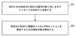
- FIG. 2 is a flowchart showing an example of the operation of AMF2 according to the present embodiment.
- AMF2 receives a message from AUSF4 indicating the revocation of authorization for a particular S-NSSAI (or network slice identified thereby) for UE1.
- AMF2 responds to the withdrawal of authorization for a particular S-NSSAI (or network slice identified thereby) for all PDU sessions associated with that particular S-NSSAI. Start the release procedure for release.
- AMF2 may initiate the PDU session release procedure in response to receiving a cancellation message from AUSF4.
- AMF2 will exclude the release of the emergency call PDU session from the above release procedure. It may be set. In other words, in the above release procedure, AMF2 may initiate a release procedure for releasing all PDU sessions associated with the particular S-NSSAI except the emergency call PDU session.
- the emergency call PDU session associated with the specific S-NSSAI is that the specific S-NSSAI is set in the AMF emergency configuration data stored in AMF2, and the S-NSSAI is notified from AMF2 to SMF3.
- the S-NSSAI may mean an emergency call PDU session that SMF3 used when establishing the PDU session.
- AMF2 is intended to release one or more PDU sessions associated with a particular S-NSSAI whose authorization has been revoked, in accordance with the PDU session release procedure described in Section 4.3.4.2 of Non-Patent Document 2.
- Nsmf_PDUSession_UpdateSMContext (or Nsmf_PDUSession_ReleaseSMContext) service operation) may be implemented (invoke).
- AMF2 may send a message containing Release Indication (eg, Nsmf_PDUSession_UpdateSMContext message) to SMF3.
- AMF2 may notify SMF3 of the PDU session ID of one or more PDU sessions associated with the S-NSSAI in order to activate the network-requested PDU session release procedure.
- the AMF2 may include these PDU session IDs in the above message, or may notify the SMF3 of these PDU session IDs by a separate message.
- AMF2 may include the S-NSSAI in the above message, or may notify SMF3 of the S-NSSAI by a separate message.
- AMF2 may send an Nsmf_PDUSession_ReleaseSMContext message to SMF3.
- the AMF2 may include the PDU session ID of one or more PDU sessions associated with the S-NSSAI in the Nsmf_PDUSession_ReleaseSMContext message.
- AMF2 may include the S-NSSAI in the Nsmf_PDUSession_ReleaseSMContext message.
- AMF2 may notify SMF3 of the revocation of authorization for a particular S-NSSAI (or network slice identified thereby) for UE1 in the PDU session release procedure. Specifically, AMF2 may send a message to SMF3 including a cause information element (Information Element (IE)) indicating the revocation of S-NSSAI (or network slice) authorization.
- the message may be, for example, an Nsmf_PDUSession_UpdateSMContext message (or an Nsmf_PDUSession_ReleaseSMContext message).
- AMF2 may notify SMF3 of cause IE indicating the revocation of S-NSSAI (or network slice) authorization in a message separate from the above message.
- AMF2 can quickly release the PDU session associated with the revoked network slice.
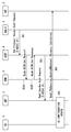
- FIG. 3 shows an example of the Slice-Specific Authorization Revocation procedure started (or triggered) by AAA-S.
- AAA-S9 requests the revocation of authorization for the network slice identified by the particular S-NSSAI (here S-NSSAI # 1).
- the AAA-S9 may send a Revoke Authorization Request message (e.g. AAA Protocol Revoke-Auth Request message) to the AUSF4.
- the message indicates S-NSSAI # 1 and further indicates UE1's Generic Public Subscription Identifier (GPSI).
- the message may be sent directly from AAA-S9 to AUSF4, or may be sent to AUSF4 via AAA Proxy (AAA-P) (not shown).
- AAA Proxy AAA Proxy
- AUFF4 notifies AMF2 via the NF service provided by AUSF4 that an S-NSSAI # 1 authorization revocation event for UE1 has occurred.
- AUSF4 acquires an AMF ID indicating AMF2 from UDM8 by invoking a procedure using GPSI of UE1 (for example, Nudm_UECM_Get procedure) included in the message received in step 301 (step 302A and). 302B).
- AUSF4 may send a message (for example, Nausf_NSSAA_Notify message) indicating that the authorization revocation event of S-NSSAI # 1 for UE1 has occurred to AMF2 indicated by the AMF ID.
- the notification from AUSF4 to AMF2 indicates S-NSSAI # 1 and further indicates the GPSI of UE1.
- step 304 if there is a UE1 PDU session associated with the revoked S-NSSAI # 1, AMF2 releases all UE1 PDU sessions associated with the S-NSSAI # 1.
- Nsmf_PDUSession_UpdateSMContext or Nsmf_PDUSession_ReleaseSMContext service operation is executed (invoke).
- AMF2 sends a message including Release Indication (for example, Nsmf_PDUSession_UpdateSMContext message) to SMF3.
- AMF2 may notify SMF3 of the PDU session ID of one or more PDU sessions associated with the S-NSSAI in order to activate the network-requested PDU session release procedure.
- the AMF2 may include these PDU session IDs in the above message, or may notify the SMF3 of these PDU session IDs by a separate message.
- AMF2 may include the S-NSSAI in the above message, or may notify SMF3 of the S-NSSAI by a separate message.
- AMF2 may send an Nsmf_PDUSession_ReleaseSMContext message to SMF3.
- the AMF2 may include the PDU session ID of one or more PDU sessions associated with the S-NSSAI in the Nsmf_PDUSession_ReleaseSMContext message.
- AMF2 may include the S-NSSAI in the Nsmf_PDUSession_ReleaseSMContext message.
- the message may include cause IE indicating the revocation of S-NSSAI (or network slice) authorization (e.g., REL_DUE_TO_SLICE_REVOCATION).
- cause IE indicating the revocation of S-NSSAI (or network slice) authorization e.g., REL_DUE_TO_SLICE_REVOCATION
- AMF2 signals UE1 and updates the UENSSAI setting (NSSAIstorage) in order to delete the revoked S-NSSAI # 1 from the current allowed NSSAI. Specifically, AMF2 sends a UE Configuration Update Command message to UE 1 indicating that S-NSSAI # 1 has been deleted from Allowed NSSAI and is included in Rejected NSSAI. In response to receiving the UE Configuration Update Command message, UE 1 updates the UE NSSAI setting (NSSAI storage) stored in the (non-volatile) memory of UE 1.
- NSSAI setting NSSAI storage
- UE1 deletes S-NSSAI # 1 from Allowed NSSAI in the UE NSSAI setting (NSSAI storage) and stores it in Rejected NSSAI.
- the UE Configuration Update Command message may include cause IE indicating the revocation of S-NSSAI (or network slice) authorization.
- the cause IE may be, for example, S-NSSAI is not available due to the failed or revoked network slice-specific authorization and authentication.
- UE1 In response to receiving the UE Configuration Update Command message, UE1 manages S-NSSAI # 1 to be included in Rejected NSSAI as Rejected S-NSSAI. In addition, UE1 may store a cause value indicating the reason for refusal (that is, authorization has been revoked) in association with the S-NSSAI # 1.
- the cause value may be network slice-specific authorization and authentication failure, or network slice-specific authorization and authentication revocation.
- UE1 After the cause of network slice-specific authorization and authentication failure has been resolved, or after the cause of revocation has been resolved, UE1 will again use S-NSSAI # 1 to enjoy the services provided by S-NSSAI # 1.
- the included Requested NSSAI may be included in the Registration request message and the message may be sent to AMF2.
- UE1 or UE1 users may know the cause of network slice-specific authorization and authentication revocation. Therefore, UE1 or the user of UE1 can perform a procedure for eliminating the cause on the network. After that, in order to enjoy the service provided by S-NSSAI # 1 again, UE1 can include the Requested NSSAI including S-NSSAI # 1 in the Registration request message and send the message to AMF2.
- AMF2 may request SMF3 to release the PDU session after the UE Configuration Update procedure (step 304).
- AMF2 may notify UDM8 of the revoked S-NSSAI # 1 before, during, or after the execution of the procedure of FIG.
- AMF2 may send the information of S-NSSAI # 1 whose authorization has been revoked to UDM8 in the Nudm_SDM_Info message, Nudm_SDM_Update message, or UEAuthentication_ResultConfirmation message.
- UDM8 updates the subscriber data with the information of S-NSSAI # 1 whose authorization has been revoked, and sends a reply message to AMF2.
- FIG. 4 shows another example of the Slice-Specific Authorization Revocation procedure initiated (or triggered) by AAA-S.
- the AMF2 requests the SMF3 to release the PDU session after the UE Configuration Update procedure (step 403) (step 405).
- Steps 401 to 403 in FIG. 4 are the same as steps 301 to 303 in FIG.
- AMF2 performs a UE Configuration Update procedure to remove the revoked S-NSSAI # 1 from the current allowed NSSAI.
- AMF2 sends a UE Configuration Update Command message to UE1 indicating that S-NSSAI # 1 has been deleted from Allowed NSSAI and is included in Rejected NSSAI.
- the UE Configuration Update Command COMMAND message may include cause IE indicating the revocation of S-NSSAI (or network slice) authorization.
- the cause IE may be, for example, S-NSSAI is not available due to the failed or revoked network slice-specific authorization and authentication.
- AMF2 includes an information element in the UE Configuration Update Command message that indicates the grace period before these PDU sessions are released. ..
- the information element may be the value of a timer used to determine the expiration of the grace period.
- the AMF2 may start the timer triggered by the transmission of the UE Configuration Update Command message. Instead, the AMF2 may start the timer by triggering the reception of a response message (for example, a UEConfigurationUpdateComplete message) to the UEConfigurationUpdateCommand message.
- AMF2 When the timer for measuring the grace period expires (step 405), AMF2 performs an Nsmf_PDUSession_UpdateSMContext (or Nsmf_PDUSession_ReleaseSMContext) service operation to release all UE1 PDU sessions associated with S-NSSAI # 1 (or Nsmf_PDUSession_ReleaseSMContext). invoke) (step 406). More specifically, AMF2 sends an Nsmf_PDUSession_UpdateSMContext message (or Nsmf_PDUSession_ReleaseSMContext message) to SMF3.
- Nsmf_PDUSession_UpdateSMContext or Nsmf_PDUSession_ReleaseSMContext
- the message may include cause IE indicating the revocation of S-NSSAI (or network slice) authorization (e.g., REL_DUE_TO_SLICE_REVOCATION). If AMF2 receives the start of the procedure to release the PDU session from UE1 before the timer for measuring the grace period expires, it stops the timer and ends the network-requested PDU session release procedure. You may.
- cause IE indicating the revocation of S-NSSAI (or network slice) authorization (e.g., REL_DUE_TO_SLICE_REVOCATION).
- AMF2 can notify UE1 that the PDU session associated with the revoked network slice will be released after the grace period has elapsed.
- FIG. 5 shows an example of the PDU session release procedure.
- AMF2 sends a message (eg, Nsmf_PDUSession_UpdateSMContext message, or Nsmf_PDUSession_ReleaseSMContext message) to SMF3 to request the release of the PDU session associated with the revoked network slice.
- the message includes Release Indication and further includes cause IE indicating the revocation of S-NSSAI (or network slice) authorization (e.g., REL_DUE_TO_SLICE_REVOCATION).
- AMF2 may notify SMF3 of the PDU session ID of one or more PDU sessions associated with the S-NSSAI in order to activate the network-requested PDU session release procedure.
- the AMF2 may include these PDU session IDs in the above message, or may notify the SMF3 of these PDU session IDs by a separate message.
- AMF2 may include the S-NSSAI in the above message, or may notify SMF3 of the S-NSSAI by a separate message.
- Step 501 corresponds to step 304 in FIG. 3 or step 406 in FIG.
- SMF3 sends a response message to AMF2.
- SMF3 may respond to AMF2 with an Nsmf_PDUSession_UpdateSMContextResponse message or an Nsmf_PDUSession_ReleaseSMContextResponse message.
- the message includes an N1SM container containing a PDU SessionReleaseCommand.
- the message may further include cause IE indicating the revocation of S-NSSAI (or network slice) authorization (e.g., REL_DUE_TO_SLICE_REVOCATION).
- the PDU SessionReleaseCommand may include 5GSMCauseIE indicating the revocation of authorization for S-NSSAI (or network slice) (or that S-NSSAI is not available).
- AMF2 transmits a NAS message including an N1SM container including a PDU SessionReleaseCommand to UE1 via AN5.
- the PDU Session Release Command may include 5GSM Cause IE indicating the revocation of authorization for S-NSSAI (or network slice) (or the S-NSSAI is not available).
- UE1 sends a NAS message including PDUSessionReleaseComplete to AMF2 in order to acknowledge the PDUSessionReleaseCommand.
- the PDU Session Release Complete may include 5GSM Cause IE indicating the revocation of S-NSSAI (or network slice) authorization.
- step 505 AMF2 implements (invoke) Nsmf_PDUSession_UpdateSMContext service operation and forwards the N1 SM container (PDU Session Release Complete) to SMF3.
- the configuration example of the cellular network according to the present embodiment may be the same as the example shown in FIG.
- the present embodiment provides another example of the operation of AMF2 when the authorization of the network slice is revoked.
- FIG. 6 is a flowchart showing an example of the operation of AMF2 according to the present embodiment.
- Step 601 is the same as step 201 of FIG. That is, AMF2 receives a message from AUSF4 indicating the revocation of authorization for a particular S-NSSAI (or network slice identified thereby) for the UE.
- AMF2 notifies SMF3 of the revocation of authorization for a particular S-NSSAI (or network slice identified thereby) for the UE.
- SMF3 Upon receiving the notification message (step 602) from AMF2, SMF3 decides to release the PDU session associated with that particular S-NSSAI.
- AMF2 will exclude the release of the emergency call PDU session from the above release procedure. It may be set. In other words, in the above release procedure, AMF2 may initiate a release procedure for releasing all PDU sessions associated with the particular S-NSSAI except the emergency call PDU session.
- the emergency call PDU session associated with the specific S-NSSAI is that the specific S-NSSAI is set in the AMF emergency configuration data stored in AMF2, and the S-NSSAI is notified from AMF2 to SMF3.
- the S-NSSAI may mean an emergency call PDU session that SMF3 used when establishing the PDU session.
- the AMF2 can notify the SMF3 of the revocation of the authorization of the network slice, thereby assisting the SMF3 to release the PDU session associated with the revoked network slice.
- the configuration example of the cellular network according to the present embodiment may be the same as the example shown in FIG.
- the present embodiment provides an example of the operation of UE1 when the authorization of the network slice is revoked.
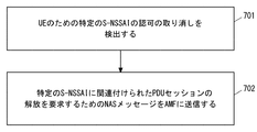
- FIG. 7 is a flowchart showing an example of the operation of UE1 according to the present embodiment.
- UE1 detects (or recognizes) the revocation of authorization for a particular S-NSSAI (or network slice identified thereby) for UE1.
- UE1 detects the revocation of authorization for a particular S-NSSAI if it receives a UEConfigurationUpdateCommand message from AMF2 indicating that the particular S-NSSAI has been removed from AllowedNSSAI and is included in the Rejected NSSAI. (Or recognition).
- UE1 detects (or recognizes) the revocation of the specific S-NSSAI authorization if it receives a NAS message from AMF2 that contains an information element indicating the revocation of the authorization of the particular S-NSSAI. ) May.
- step 702 in response to the revocation of authorization for a particular S-NSSAI (or network slice identified thereby), UE1 releases the PDU session associated with that particular S-NSSAI. Request to the network. Specifically, UE1 sends a NAS message to AMF2 requesting the release of the PDU session associated with the particular S-NSSAI. More specifically, the NAS-MM layer of UE1 notifies the NAS-SM layer of UE1 of the revocation of the authorization of a specific S-NSSAI.
- the NAS-SM layer of UE1 responds to the notification from the lower layer (NAS-MM layer) and generates a PDU Session Release Request regarding the PDU session associated with the specific S-NSSAI whose authorization has been revoked.
- the NAS-SM layer of UE1 passes the generated PDUSessionReleaseRequest to the NAS-MM layer together with the PDUSessionID.
- the NAS-MM layer of UE1 transmits a NAS message including a PDU Session ID and an N1 SM container (PDU Session Release Request) to AMF2.
- One or both of the NAS message and the PDU Session Release Request may include a cause information element indicating the revocation of S-NSSAI authorization.
- UE1 can quickly release the PDU session associated with the revoked network slice.
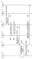
- FIG. 8 shows an example of the Slice-Specific Authorization Revocation procedure started (or triggered) by AAA-S. Steps 801 to 804 may be the same as the existing procedure.
- the Slice-Specific Authorization Revocation procedure initiated (or triggered) by an existing AAA-S is described in Section 4.2.9.4 (or Non-Patent Document 5) of Non-Patent Document 2.
- the AAA-S9 requests a Revoke Authorization Request message (eg AAA Protocol Revoke) to request the revocation of authorization for the network slice identified by the particular S-NSSAI (here S-NSSAI # 1).
- a Revoke Authorization Request message eg AAA Protocol Revoke
- -AuthRequest message is sent to AUSF4.
- the message indicates S-NSSAI # 1 and further indicates UE1's Generic Public Subscription Identifier (GPSI).
- the message may be sent directly from AAA-S9 to AUSF4, or may be sent to AUSF4 via AAA Proxy (AAA-P) (not shown).
- AUFF4 notifies AMF2 via the NF service provided by AUSF4 that an S-NSSAI # 1 authorization revocation event for UE1 has occurred.
- AUSF4 acquires an AMF ID indicating AMF2 from UDM8 by invoking a procedure using GPSI of UE1 (for example, Nudm_UECM_Get procedure) included in the message received in step 801 (step 802A and). 802B).
- AUSF4 may send a message (for example, Nausf_NSSAA_Notify message) indicating that the authorization revocation event of S-NSSAI # 1 for UE1 has occurred to AMF2 indicated by the AMF ID.
- the notification message from AUSF4 to AMF2 indicates S-NSSAI # 1 and further indicates GPSI of UE1.
- AMF2 signals UE1 and updates the UE NSSAI setting (NSSAI storage) in order to delete the revoked S-NSSAI # 1 from the current allowed NSSAI. Specifically, AMF2 sends a UE Configuration Update Command message to UE 1 indicating that S-NSSAI # 1 has been deleted from Allowed NSSAI and is included in Rejected NSSAI. In response to receiving the UE Configuration Update Command message, UE 1 updates the UE NSSAI setting (NSSAI storage) stored in the (non-volatile) memory of UE 1.
- UE1 deletes S-NSSAI # 1 from Allowed NSSAI in the UE NSSAI setting (NSSAI storage) and stores it in Rejected NSSAI.
- the UE Configuration Update Command message may include cause IE indicating the revocation of S-NSSAI (or network slice) authorization.
- the cause IE may be, for example, S-NSSAI is not available due to the failed or revoked network slice-specific authorization and authentication.
- UE1 requests the network to release the PDU session associated with S-NSSAI # 1 in response to detecting the revocation of authorization for S-NSSAI # 1. Specifically, UE1 transmits a NAS message including the PDU Session ID of the PDU session associated with S-NSSAI # 1 and the N1 SM container (PDU Session Release Request) to AMF2. As mentioned above, one or both of the NAS message and the PDU Session Release Request may include cause IE indicating the revocation of S-NSSAI authorization.
- step 806 AMF2 executes (invoke) Nsmf_PDUSession_UpdateSMContext service operation and forwards N1 SM container (PDU Session Release Request) to SMF3.
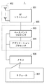
- FIG. 9 is a block diagram showing a configuration example of UE1.
- Radio Frequency (RF) transceiver 901 performs analog RF signal processing to communicate with NG-RAN nodes.
- the RF transceiver 901 may include a plurality of transceivers.
- the analog RF signal processing performed by the RF transceiver 901 includes frequency up-conversion, frequency down-conversion, and amplification.
- the RF transceiver 901 is coupled with the antenna array 902 and the baseband processor 903.
- the RF transceiver 901 receives the modulation symbol data (or OFDM symbol data) from the baseband processor 903, generates a transmit RF signal, and supplies the transmit RF signal to the antenna array 902. Further, the RF transceiver 901 generates a baseband reception signal based on the reception RF signal received by the antenna array 902, and supplies the baseband reception signal to the baseband processor 903.
- the RF transceiver 901 may include an analog beamformer circuit for beamforming.
- the analog beamformer circuit includes, for example, a plurality of phase shifters and a plurality of power amplifiers.
- the baseband processor 903 performs digital baseband signal processing (data plane processing) and control plane processing for wireless communication.
- Digital baseband signal processing includes (a) data compression / restoration, (b) data segmentation / concatenation, (c) transmission format (transmission frame) generation / decomposition, and (d) transmission path coding / decoding. , (E) Modulation (symbol mapping) / demodulation, and (f) Generation of OFDM symbol data (baseband OFDM signal) by Inverse Fast Fourier Transform (IFFT).
- the control plane processing includes layer 1 (eg, transmission power control), layer 2 (eg, radio resource management, and hybrid automatic repeat request (HARQ) processing), and layer 3 (eg, attach, mobility, and call management). Includes communication management of).
- digital baseband signal processing by the baseband processor 903 is performed by the ServiceDataAdaptationProtocol (SDAP) layer, PacketDataConvergenceProtocol (PDCP) layer, RadioLinkControl (RLC) layer, MediumAccessControl (MAC) layer, and Physical. (PHY) layer signal processing may be included.
- SDAP ServiceDataAdaptationProtocol
- PDCP PacketDataConvergenceProtocol
- RLC RadioLinkControl
- MAC MediumAccessControl
- PHY Physical.
- control plane processing by the baseband processor 903 may include the processing of the Non-Access Stratum (NAS) protocol, the Radio Resource Control (RRC) protocol, and the MAC Control Elements (CEs).
- NAS Non-Access Stratum
- RRC Radio Resource Control
- CEs MAC Control Elements
- the baseband processor 903 may perform MultipleInputMultipleOutput (MIMO) encoding and precoding for beamforming.
- MIMO MultipleInputMultipleOutput
- the baseband processor 903 includes a modem processor (eg, Digital Signal Processor (DSP)) that performs digital baseband signal processing and a protocol stack processor (eg, Central Processing Unit (CPU) or Micro Processing Unit (eg, Central Processing Unit (CPU)) that performs control plane processing. MPU)) may be included.
- DSP Digital Signal Processor
- MPU Central Processing Unit
- the protocol stack processor that performs the control plane processing may be shared with the application processor 904 described later.
- the application processor 904 is also called a CPU, MPU, microprocessor, or processor core.
- the application processor 904 may include a plurality of processors (a plurality of processor cores).
- the application processor 904 is a system software program (Operating System (OS)) read from memory 906 or a memory (not shown) and various application programs (eg, call application, web browser, mailer, camera operation application, music playback). By executing the application), various functions of UE1 are realized.
- OS Operating System
- the baseband processor 903 and the application processor 904 may be integrated on one chip, as shown by the dashed line (905) in FIG.
- the baseband processor 903 and the application processor 904 may be implemented as one System on Chip (SoC) device 905.
- SoC devices are sometimes referred to as system Large Scale Integration (LSI) or chipsets.
- the memory 906 is a volatile memory, a non-volatile memory, or a combination thereof.
- the memory 906 may include a plurality of physically independent memory devices.
- the volatile memory is, for example, Static Random Access Memory (SRAM) or Dynamic RAM (DRAM) or a combination thereof.
- the non-volatile memory is a mask ReadOnlyMemory (MROM), Electrically ErasableProgrammableROM (EEPROM), flash memory, or hard disk drive, or any combination thereof.
- MROM ReadOnlyMemory
- EEPROM Electrically ErasableProgrammableROM
- flash memory or hard disk drive, or any combination thereof.
- memory 906 may include external memory devices accessible from baseband processor 903, application processor 904, and SoC 905.
- the memory 906 may include an internal memory device integrated in the baseband processor 903, the application processor 904, or the SoC 905.
- the memory 906 may include a memory in a Universal Integrated Circuit Card (UICC).
- UICC Universal Integrated
- the memory 906 may store one or more software modules (computer programs) 907 including instruction groups and data for performing processing by UE1 described in the plurality of embodiments described above.
- the baseband processor 903 or application processor 904 is configured to read the software module 907 from memory 906 and execute it to perform the processing of UE1 described with reference to the drawings in the above embodiments. May be done.
- control plane processing and operation performed by UE1 described in the above-described embodiment is performed by other elements other than the RF transceiver 901 and the antenna array 902, that is, at least one of the baseband processor 903 and the application processor 904, and the software module 907. It can be realized by the memory 906 that stores the above.
- FIG. 10 shows a configuration example of AMF2.
- SMF3 may also be configured as shown in FIG.
- AMF2 includes a network interface 1001, a processor 1002, and a memory 1003.
- Network interface 1001 is used, for example, to communicate with RAN nodes and to communicate with other network functions (NFs) or nodes within 5GC.
- NFs network functions
- Other NFs or nodes within the 5GC include, for example, UDM, AUSF, SMF, and PCF.
- the network interface 1001 may include, for example, a network interface card (NIC) compliant with the IEEE 802.3 series.
- NIC network interface card
- the processor 1002 may be, for example, a microprocessor, a MicroProcessingUnit (MPU), or a CentralProcessingUnit (CPU). Processor 1002 may include a plurality of processors.
- MPU MicroProcessingUnit
- CPU CentralProcessingUnit
- Memory 1003 is composed of a volatile memory and a non-volatile memory.
- the memory 1003 may include a plurality of physically independent memory devices.
- the volatile memory is, for example, Static Random Access Memory (SRAM) or Dynamic RAM (DRAM) or a combination thereof.
- the non-volatile memory is a mask ReadOnlyMemory (MROM), Electrically ErasableProgrammableROM (EEPROM), flash memory, or hard disk drive, or any combination thereof.
- Memory 1003 may include storage located away from processor 1002. In this case, processor 1002 may access memory 1003 via network interface 1001 or an I / O interface (not shown).
- the memory 1003 may store one or more software modules (computer programs) 1004 including instruction groups and data for performing processing by AMF2 described in the plurality of embodiments described above.
- processor 1002 may be configured to perform the processing of AMF2 described in the embodiments described above by reading the software module 1004 from memory 1003 and executing it.
- each of the processors included in UE1, AMF2, and SMF3 provides a group of instructions for causing the computer to perform the algorithm described with reference to the drawings.
- This program can be stored and supplied to a computer using various types of non-transitory computer readable medium.
- Non-temporary computer-readable media include various types of tangible storage media. Examples of non-temporary computer-readable media include magnetic recording media (eg flexible disks, magnetic tapes, hard disk drives), magneto-optical recording media (eg magneto-optical disks), CompactDiscReadOnlyMemory (CD-ROM), CD-ROM.
- the program may also be supplied to the computer by various types of temporary computer readable medium.
- temporary computer-readable media include electrical, optical, and electromagnetic waves.
- the temporary computer-readable medium can supply the program to the computer via a wired communication path such as an electric wire and an optical fiber, or a wireless communication path.
- the wireless terminal (User Equipment (UE)) in the present specification is an entity connected to a network via a wireless interface.
- the wireless terminal (UE) of the present specification is not limited to a dedicated communication device, and is any device as follows having the communication function of the wireless terminal (UE) described in the present specification. You may.
- the terms “wireless device” are generally intended to be synonymous with each other.
- the UE may be a stand-alone mobile station such as a terminal, mobile phone, smartphone, tablet, cellular IoT terminal, IoT device, and the like.
- the terms “UE” and “wireless terminal” also include devices that are stationary for extended periods of time.
- UE is, for example, production equipment / manufacturing equipment and / or energy related machinery (for example, boilers, engines, turbines, solar panels, wind generators, hydraulic generators, thermal power generators, nuclear generators, storage batteries, nuclear systems, etc.
- Pumps including nuclear equipment, heavy electrical equipment, vacuum pumps, compressors, fans, blowers, hydraulic equipment, pneumatic equipment, metal processing machines, manipulators, robots, robot application systems, tools, molds, rolls, conveyors, Lifting device, cargo handling device, textile machine, sewing machine, printing machine, printing related machine, paperwork machine, chemical machine, mining machine, mining related machine, construction machine, construction related machine, agricultural machine and / or equipment, for forestry Machinery and / or equipment, fishing machinery and / or equipment, safety and / or environmental protection equipment, tractors, bearings, precision bearings, chains, gears, power transmissions, lubricators, valves, pipe fittings, and / Alternatively, it may be any device or machine application system described above).
- UE is, for example, transportation equipment (for example, vehicles, automobiles, two-wheeled vehicles, bicycles, trains, buses, rear cars, rickshaws, ships (ship and other watercraft), airplanes, rockets, artificial satellites, drones, balloons, etc.) There may be.
- transportation equipment for example, vehicles, automobiles, two-wheeled vehicles, bicycles, trains, buses, rear cars, rickshaws, ships (ship and other watercraft), airplanes, rockets, artificial satellites, drones, balloons, etc.
- the UE may be, for example, an information communication device (for example, a computer and related devices, a communication device and related devices, electronic components, etc.).
- an information communication device for example, a computer and related devices, a communication device and related devices, electronic components, etc.
- UEs are, for example, refrigerating machines, refrigerating machine application products and equipment, commercial and service equipment, vending machines, automatic service machines, office machinery and equipment, consumer electrical and electronic machinery and equipment (for example, audio equipment, speakers, etc. Radios, video equipment, televisions, oven ranges, rice cookers, coffee makers, dishwashers, washing machines, dryers, electric fans, ventilation fans and related products, vacuum cleaners, etc.) may be used.
- the UE may be, for example, an electronic application system or an electronic application device (for example, an X-ray device, a particle accelerator, a radioactive material application device, a sound wave application device, an electromagnetic application device, a power application device, etc.).
- an electronic application system for example, an X-ray device, a particle accelerator, a radioactive material application device, a sound wave application device, an electromagnetic application device, a power application device, etc.
- UEs include, for example, light bulbs, lights, weighing machines, analyzers, testing machines and measuring machines (for example, smoke alarms, personal alarm sensors, motion sensors, wireless tags, etc.), watches or clocks, physics and chemistry machines, etc. It may be an optical machine, a medical device and / or a medical system, a weapon, a clockwork tool, or a hand tool.
- the UE is, for example, a personal digital assistant or device with wireless communication capabilities (for example, an electronic device (eg, a personal computer, electronic measuring instrument, etc.) configured to attach or insert a wireless card, wireless module, etc.). ) May be.
- a personal digital assistant or device with wireless communication capabilities for example, an electronic device (eg, a personal computer, electronic measuring instrument, etc.) configured to attach or insert a wireless card, wireless module, etc.).
- the UE may be, for example, a device or a part thereof that provides the following applications, services, and solutions in the "Internet of Things (IoT)" using wired or wireless communication technology.
- IoT devices include suitable electronic devices, software, sensors, network connections, etc. that allow devices to collect and exchange data with each other and with other communication devices.
- the IoT device may be an automated device that complies with software directives stored in internal memory. IoT devices may operate without the need for human supervision or response.
- the IoT device may remain inactive for a long period of time and / or for a long period of time. IoT devices can be implemented as part of a stationary device.
- IoT devices can be embedded in non-stationary devices (such as vehicles) or attached to animals or people that are monitored / tracked. IoT technology can be implemented on any communication device that can be connected to a communication network that sends and receives data regardless of human input control or software instructions stored in memory.
- the IoT device is sometimes called a Machine Type Communication (MTC) device, a Machine to Machine (M2M) communication device, or a Narrow Band-IoT (NB-IoT) UE.
- MTC Machine Type Communication
- M2M Machine to Machine
- NB-IoT Narrow Band-IoT
- the UE may support one or more IoT or MTC applications.
- MTC applications are listed in the list shown in 3GPP TS22.368 V13.2.0 (2017-01-13) Annex B (whose content is incorporated herein by reference). This list is not exhaustive and shows an example MTC application.
- the Service Area of the MTC application is Security, Tracking & Tracing, Payment, Health, Remote Maintenance / Control, Includes Metering and Consumer Devices.
- MTC applications related to security are surveillance systems (Surveillance systems), landline backups (Backup for landscape), physical access control (eg building access) (Control of physical access (eg to buildings)), and vehicles / Includes driver security (Car / driver security).
- MTC applications for tracking and tracing are Fleet Management, Order Management, Telematics Insurance: Pay as you drive (PAYD), Asset Tracking, Navigation. Includes (Navigation), Traffic information, Road tolling, and Road traffic optimization / steering.
- MTC applications related to payment include point-of-sale information management (Point of sales (POS)), vending machines (Vending machines), and amusement machines (Gaming machines).
- POS Point of sales
- Vending machines vending machines
- Giaming machines amusement machines
- Examples of health-related MTC applications are Monitoring vital signs, Supporting the aged or handicapped, Web Access Telemedicine points, and Remote diagnostics. including.
- MTC applications for remote maintenance / control are Sensors, Lighting, Pumps, Valves, Elevator control, Vending machine control, and vehicles. Includes diagnostics.
- MTC applications for weighing are Power, Gas. Includes Water, Heating, Grid control, and Industrial metering.
- Examples of MTC applications for consumer devices include digital photo frames, digital cameras, and ebooks.
- MVNO Mobile Virtual Network Operator
- PBX Private Branch eXchange
- MVNO Mobile Virtual Network Operator
- PHS Digital Cordless Telephone Service
- POS Point of sales
- Advertising Service / System Advertising Service / System
- Multimedia Broadcast and Multicast Service (MBMS) Service / System V2X (Vehicle to Everything: Vehicle-to-Vehicle Communication And road-to-vehicle / pedestrian communication) services / systems, in-train mobile wireless services / systems, location information-related services / systems, disaster / emergency wireless communication services / systems, IoT (Internet of Things) services / systems , Community service / system, video distribution service / system, Femto cell application service / system, VoLTE (Voice over LTE) service / system, wireless tag service / system, billing service / system, radio on-demand service / system, roaming service / System, user
- VoLTE Voice over LTE
- the UE category described above is merely an application example of the technical idea and the embodiment described in the present specification.
- the UEs herein are not limited to these examples, and one of ordinary skill in the art can make various modifications to them.
- Appendix 1 With at least one memory With at least one processor coupled to the at least one memory With The at least one processor responds to a revocation of authorization of the first network slice identifier for User Equipment (UE) by the Protocol Data Unit associated with the first network slice identifier.
- PDU Configured to initiate a release procedure to release a session, Access and Mobility Management Function (AMF) node.
- AMF Access and Mobility Management Function
- the at least one processor is configured to notify the Session Management Function (SMF) of the revocation of authorization of the first network slice identifier for the UE in the release procedure.
- SMF Session Management Function
- the at least one processor is configured to send a message to the SMF requesting the release of the Session Management (SM) context for the PDU session in the release procedure.
- the message includes a cause information element indicating the withdrawal of the authorization.
- the at least one processor is configured to send a Non-Access Stratum (NAS) message to the UE in response to the withdrawal of the authorization, instructing the UE configuration to be updated.
- the NAS message removes the first network slice identifier from the set of allowed network slice identifiers indicating one or more network slice identifiers currently allowed to the UE, and rejects the network slice. Indicates that the set of identifiers includes the first network slice identifier.
- the NAS message further indicates a grace period before the PDU session is released.
- the AMF node according to any one of Appendix 1 to 3.
- the at least one processor is configured to initiate the release procedure after the grace period has elapsed.
- the at least one processor is configured to initiate the release procedure in response to receiving a message from the Authentication Server Function (AUSF) indicating the revocation of the authorization.
- AUSF Authentication Server Function
- the AMF node according to any one of Appendix 1 to 5.
- the first network slice identifier is Single Network Slice Selection Assistance Information (S-NSSAI).
- S-NSSAI Single Network Slice Selection Assistance Information
- UE User Equipment
- PDU Protocol Data Unit
- AMF Access and Mobility Management Function
- the at least one processor is configured to receive a second Non-Access Stratum (NAS) message from the Access and Mobility Management Function (AMF) instructing it to update the UE settings.
- the second NAS message removes and rejects the first network slice identifier from the set of allowed network slice identifiers indicating one or more network slice identifiers currently allowed to the UE. It is shown that the first network slice identifier is included in the set of network slice identifiers.
- the at least one processor is configured to detect the revocation of the authorization based on the second NAS message.
- the UE according to Appendix 10 or 11.
- (Appendix 13) It is a method in User Equipment (UE) Requests the network to release the Protocol Data Unit (PDU) session associated with the first network slice identifier in response to a revocation of authorization of the first network slice identifier for the UE. Prepare to do Method.
- (Appendix 14) A program that lets a computer do the methods in User Equipment (UE). The method releases a Protocol Data Unit (PDU) session associated with the first network slice identifier in response to a revocation of authorization of the first network slice identifier for the UE. Prepare to request the network, program.
Landscapes
- Engineering & Computer Science (AREA)
- Computer Networks & Wireless Communication (AREA)
- Signal Processing (AREA)
- Computer Security & Cryptography (AREA)
- Mobile Radio Communication Systems (AREA)
Abstract
Description
図1は、本実施形態に係るセルラーネットワーク(i.e., 5GS)の構成例を示している。図1に示された要素の各々はネットワーク機能であり、3rd Generation Partnership Project(3GPP)により定義されたインタフェースを提供する。図1に示された各要素(ネットワーク機能)は、例えば、専用ハードウェア(dedicated hardware)上のネットワークエレメントとして、専用ハードウェア上で動作する(running)ソフトウェア・インスタンスとして、又はアプリケーション・プラットフォーム上にインスタンス化(instantiated)された仮想化機能として実装されることができる。
本実施形態に係るセルラーネットワークの構成例は、図1に示された例と同様であってもよい。本実施形態は、ネットワークスライスの認可が取り消された場合のAMF2の動作の他の例を提供する。
本実施形態に係るセルラーネットワークの構成例は、図1に示された例と同様であってもよい。本実施形態は、ネットワークスライスの認可が取り消された場合のUE1の動作の一例を提供する。
水 (Water)、暖房 (Heating)、グリッド制御 (Grid control)、及び産業用メータリング (Industrial metering)を含む。
少なくとも1つのメモリと、
前記少なくとも1つのメモリに結合された少なくとも1つのプロセッサと、
を備え、
前記少なくとも1つのプロセッサは、User Equipment(UE)のための第1のネットワークスライス識別子の認可(authorization)の取り消し(revocation)に応答して、前記第1のネットワークスライス識別子に関連付けられたProtocol Data Unit(PDU)セッションを解放するための解放手順を開始するよう構成される、
Access and Mobility Management Function(AMF)ノード。
(付記2)
前記少なくとも1つのプロセッサは、前記解放手順において、前記UEのための前記第1のネットワークスライス識別子の認可の取り消しをSession Management Function(SMF)に通知するよう構成される、
付記1に記載のAMFノード。
(付記3)
前記少なくとも1つのプロセッサは、前記解放手順において、前記PDUセッションのためのSession Management(SM)コンテキストの解放を要求するためのメッセージを前記SMFに送信するよう構成され、
前記メッセージは、前記認可の前記取り消しを示すcause情報要素を包含する、
付記2に記載のAMFノード。
(付記4)
前記少なくとも1つのプロセッサは、前記認可の前記取り消しに応答して、UE設定の更新を指示するNon-Access Stratum(NAS)メッセージを前記UEに送信するよう構成され、
前記NASメッセージは、前記UEに現在許可された1又はそれ以上のネットワークスライス識別子を示す許可されたネットワークスライス識別子のセットから前記第1のネットワークスライス識別子が削除されること、及び拒絶されたネットワークスライス識別子のセットに前記第1のネットワークスライス識別子が含まれることを示し、
前記NASメッセージは、さらに、前記PDUセッションが解放されるまでの猶予期間を示す、
付記1~3のいずれか1項に記載のAMFノード。
(付記5)
前記少なくとも1つのプロセッサは、前記猶予期間の経過後に前記解放手順を開始するよう構成される、
付記4に記載のAMFノード。
(付記6)
前記少なくとも1つのプロセッサは、前記認可の前記取り消しを示すメッセージをAuthentication Server Function(AUSF)から受信したことに応答して、前記解放手順を開始するよう構成される、
付記1~5のいずれか1項に記載のAMFノード。
(付記7)
前記第1のネットワークスライス識別子は、Single Network Slice Selection Assistance Information(S-NSSAI)である、
付記1~6のいずれか1項に記載のAMFノード。
(付記8)
User Equipment(UE)のための第1のネットワークスライス識別子の認可(authorization)の取り消し(revocation)に応答して、前記第1のネットワークスライス識別子に関連付けられたProtocol Data Unit(PDU)セッションを解放するための解放手順を開始することを備える、
Access and Mobility Management Function(AMF)ノードにおける方法。
(付記9)
Access and Mobility Management Function(AMF)ノードにおける方法をコンピュータに行わせるためのプログラムであって、
前記方法は、User Equipment(UE)のための第1のネットワークスライス識別子の認可(authorization)の取り消し(revocation)に応答して、前記第1のネットワークスライス識別子に関連付けられたProtocol Data Unit(PDU)セッションを解放するための解放手順を開始することを備える、
プログラム。
(付記10)
User Equipment(UE)であって、
少なくとも1つのメモリと、
前記少なくとも1つのメモリに結合された少なくとも1つのプロセッサと、
を備え、
前記少なくとも1つのプロセッサは、前記UEのための第1のネットワークスライス識別子の認可(authorization)の取り消し(revocation)に応答して、前記第1のネットワークスライス識別子に関連付けられたProtocol Data Unit(PDU)セッションの解放をネットワークに要求するよう構成される、
UE。
(付記11)
前記少なくとも1つのプロセッサは、前記PDUセッションの解放を要求するための第1のNon-Access Stratum(NAS)メッセージをAccess and Mobility Management Function(AMF)に送信するよう構成され、
前記第1のNASメッセージは、前記認可の前記取り消しを示すcause情報要素を包含する、
付記10に記載のUE。
(付記12)
前記少なくとも1つのプロセッサは、UE設定の更新を指示する第2のNon-Access Stratum(NAS)メッセージをAccess and Mobility Management Function(AMF)から受信するよう構成され、
前記第2のNASメッセージは、前記UEに現在許可された1又はそれ以上のネットワークスライス識別子を示す許可されたネットワークスライス識別子のセットから前記第1のネットワークスライス識別子が削除されること、及び拒絶されたネットワークスライス識別子のセットに前記第1のネットワークスライス識別子が含まれることを示し、
前記少なくとも1つのプロセッサは、前記第2のNASメッセージに基づいて前記認可の取り消しを検出するよう構成される、
付記10又は11に記載のUE。
(付記13)
User Equipment(UE)における方法であって、
前記UEのための第1のネットワークスライス識別子の認可(authorization)の取り消し(revocation)に応答して、前記第1のネットワークスライス識別子に関連付けられたProtocol Data Unit(PDU)セッションの解放をネットワークに要求することを備える、
方法。
(付記14)
User Equipment(UE)における方法をコンピュータに行わせるためのプログラムであって、
前記方法は、前記UEのための第1のネットワークスライス識別子の認可(authorization)の取り消し(revocation)に応答して、前記第1のネットワークスライス識別子に関連付けられたProtocol Data Unit(PDU)セッションの解放をネットワークに要求することを備える、
プログラム。
2 AMF
3 SMF
4 AUSF
5 AN
6 UPF
7 DN
8 UDM
9 AAA-S
903 ベースバンドプロセッサ
904 アプリケーションプロセッサ
906 メモリ
907 モジュール(modules)
1002 プロセッサ
1003 メモリ
1004 モジュール(modules)
Claims (12)
- メモリと、
前記メモリに結合された少なくとも1つのプロセッサと、
を備え、
前記少なくとも1つのプロセッサは、User Equipment(UE)のための第1のネットワークスライス識別子の認可(authorization)の取り消し(revocation)に応答して、前記第1のネットワークスライス識別子に関連付けられたProtocol Data Unit(PDU)セッションを解放するための解放手順を開始するよう構成される、
Access and Mobility Management Function(AMF)ノード。 - 前記少なくとも1つのプロセッサは、前記解放手順において、前記PDUセッションのためのSession Management(SM)コンテキストの解放を要求するためのメッセージをSession Management Function(SMF)に送信するよう構成され、
前記メッセージは、前記認可の前記取り消しを示すcause情報要素を包含する、
請求項1に記載のAMFノード。 - 前記少なくとも1つのプロセッサは、前記認可の前記取り消しに応答して、UE設定の更新を指示するNon-Access Stratum(NAS)メッセージを前記UEに送信するよう構成され、
前記NASメッセージは、前記UEに現在許可された少なくとも1つのネットワークスライス識別子を示す許可されたネットワークスライス識別子のセットから前記第1のネットワークスライス識別子が削除されること、及び拒絶されたネットワークスライス識別子のセットに前記第1のネットワークスライス識別子が含まれることを示す、
請求項1又は2に記載のAMFノード。 - 前記少なくとも1つのプロセッサは、前記解放手順において、前記PDUセッションの解放を示すメッセージを前記UEに送信するよう構成され、
前記PDUセッションの解放を示すメッセージは、前記認可の前記取り消しを示すcause情報要素を包含する、
請求項1~3のいずれか1項に記載のAMFノード。 - 前記少なくとも1つのプロセッサは、前記認可の前記取り消しを示すメッセージを、ネットワークスライスに特化した認証及び認可サービスを提供するAuthentication Server Functionから受信したことに応答して、前記解放手順を開始するよう構成される、
請求項1~4のいずれか1項に記載のAMFノード。 - 前記第1のネットワークスライス識別子は、Single Network Slice Selection Assistance Information(S-NSSAI)である、
請求項1~5のいずれか1項に記載のAMFノード。 - User Equipment(UE)のための第1のネットワークスライス識別子の認可(authorization)の取り消し(revocation)に応答して、前記第1のネットワークスライス識別子に関連付けられたProtocol Data Unit(PDU)セッションを解放するための解放手順を開始することを備える、
Access and Mobility Management Function(AMF)ノードにおける方法。 - 前記解放手順において、前記PDUセッションのためのSession Management(SM)コンテキストの解放を要求するためのメッセージをSession Management Function(SMF)に送信することを備え、
前記メッセージは、前記認可の前記取り消しを示すcause情報要素を包含する、
請求項7に記載の方法。 - 前記認可の前記取り消しに応答して、UE設定の更新を指示するNon-Access Stratum(NAS)メッセージを前記UEに送信することを備え、
前記NASメッセージは、前記UEに現在許可された少なくとも1つのネットワークスライス識別子を示す許可されたネットワークスライス識別子のセットから前記第1のネットワークスライス識別子が削除されること、及び拒絶されたネットワークスライス識別子のセットに前記第1のネットワークスライス識別子が含まれることを示す、
請求項7又は8に記載の方法。 - 前記解放手順において、前記PDUセッションの解放を示すメッセージを前記UEに送信することを備え、
前記PDUセッションの解放を示すメッセージは、前記認可の前記取り消しを示すcause情報要素を包含する、
請求項7~9のいずれか1項に記載の方法。 - 前記認可の前記取り消しを示すメッセージを、ネットワークスライスに特化した認証及び認可サービスを提供するAuthentication Server Functionから受信したことに応答して、前記解放手順を開始する、
請求項7~10のいずれか1項に記載の方法。 - 前記第1のネットワークスライス識別子は、Single Network Slice Selection Assistance Information(S-NSSAI)である、
請求項7~11のいずれか1項に記載の方法。
Priority Applications (6)
| Application Number | Priority Date | Filing Date | Title |
|---|---|---|---|
| EP20905450.1A EP3993560A4 (en) | 2019-12-26 | 2020-12-18 | Amf node and method therefor |
| CN202410867300.3A CN118890624A (zh) | 2019-12-26 | 2020-12-18 | 第一通信设备、用户设备及其方法 |
| CN202080057518.2A CN114223234B (zh) | 2019-12-26 | 2020-12-18 | Amf节点及其方法 |
| US17/629,610 US12295066B2 (en) | 2019-12-26 | 2020-12-18 | AMF node and method thereof |
| JP2021567408A JP7533485B2 (ja) | 2019-12-26 | 2020-12-18 | 第1の通信装置及びその方法 |
| US19/096,836 US20250261280A1 (en) | 2019-12-26 | 2025-04-01 | Amf node and method thereof |
Applications Claiming Priority (2)
| Application Number | Priority Date | Filing Date | Title |
|---|---|---|---|
| JP2019237392 | 2019-12-26 | ||
| JP2019-237392 | 2019-12-26 |
Related Child Applications (2)
| Application Number | Title | Priority Date | Filing Date |
|---|---|---|---|
| US17/629,610 A-371-Of-International US12295066B2 (en) | 2019-12-26 | 2020-12-18 | AMF node and method thereof |
| US19/096,836 Continuation US20250261280A1 (en) | 2019-12-26 | 2025-04-01 | Amf node and method thereof |
Publications (1)
| Publication Number | Publication Date |
|---|---|
| WO2021132096A1 true WO2021132096A1 (ja) | 2021-07-01 |
Family
ID=76574152
Family Applications (1)
| Application Number | Title | Priority Date | Filing Date |
|---|---|---|---|
| PCT/JP2020/047499 Ceased WO2021132096A1 (ja) | 2019-12-26 | 2020-12-18 | Amfノード及びその方法 |
Country Status (5)
| Country | Link |
|---|---|
| US (2) | US12295066B2 (ja) |
| EP (1) | EP3993560A4 (ja) |
| JP (1) | JP7533485B2 (ja) |
| CN (2) | CN114223234B (ja) |
| WO (1) | WO2021132096A1 (ja) |
Cited By (3)
| Publication number | Priority date | Publication date | Assignee | Title |
|---|---|---|---|---|
| WO2023067815A1 (ja) * | 2021-10-22 | 2023-04-27 | 株式会社Nttドコモ | ネットワークノード及び通信方法 |
| WO2023188727A1 (ja) * | 2022-03-29 | 2023-10-05 | シャープ株式会社 | UE(User Equipment) |
| WO2023195370A1 (ja) * | 2022-04-06 | 2023-10-12 | 株式会社Nttドコモ | ネットワークノード及び通信方法 |
Families Citing this family (5)
| Publication number | Priority date | Publication date | Assignee | Title |
|---|---|---|---|---|
| CN113498060B (zh) * | 2020-04-07 | 2023-02-17 | 大唐移动通信设备有限公司 | 一种控制网络切片认证的方法、装置、设备及存储介质 |
| WO2021247725A1 (en) * | 2020-06-02 | 2021-12-09 | Ofinno, Llc | Network slice specific authentication and authorization |
| CN116685969A (zh) * | 2021-01-08 | 2023-09-01 | 联想(新加坡)私人有限公司 | Uas相关的授权和安全信息的撤销 |
| KR20230107095A (ko) * | 2022-01-07 | 2023-07-14 | 엘지전자 주식회사 | 무선 통신 시스템에서 단말 인증 취소 방법 및 장치 |
| CN118575521A (zh) * | 2022-12-29 | 2024-08-30 | 北京小米移动软件有限公司 | 一种网络切片的授权方法、装置、设备及存储介质 |
Family Cites Families (8)
| Publication number | Priority date | Publication date | Assignee | Title |
|---|---|---|---|---|
| CN108234401B (zh) * | 2016-12-15 | 2020-09-11 | 腾讯科技(深圳)有限公司 | 一种对业务系统授权的方法及装置 |
| US10531420B2 (en) * | 2017-01-05 | 2020-01-07 | Huawei Technologies Co., Ltd. | Systems and methods for application-friendly protocol data unit (PDU) session management |
| US10728952B2 (en) * | 2017-01-09 | 2020-07-28 | Huawei Technologies Co., Ltd. | System and methods for session management |
| EP4642084A3 (en) * | 2017-12-08 | 2026-01-14 | Comcast Cable Communications, LLC | User plane function selection for isolated network slice |
| US20200413241A1 (en) * | 2018-02-19 | 2020-12-31 | Lg Electronics Inc. | Method for terminal setting update in wireless communication system and apparatus therefor |
| JP7240227B2 (ja) * | 2019-04-01 | 2023-03-15 | シャープ株式会社 | Ue、及び通信制御方法 |
| WO2021236913A1 (en) * | 2020-05-20 | 2021-11-25 | Ryu Jinsook | Network slice specific authentication and authorization |
| CN116438823A (zh) * | 2020-10-02 | 2023-07-14 | 欧芬诺有限责任公司 | 航空系统的认证和授权 |
-
2020
- 2020-12-18 CN CN202080057518.2A patent/CN114223234B/zh active Active
- 2020-12-18 JP JP2021567408A patent/JP7533485B2/ja active Active
- 2020-12-18 CN CN202410867300.3A patent/CN118890624A/zh active Pending
- 2020-12-18 EP EP20905450.1A patent/EP3993560A4/en active Pending
- 2020-12-18 US US17/629,610 patent/US12295066B2/en active Active
- 2020-12-18 WO PCT/JP2020/047499 patent/WO2021132096A1/ja not_active Ceased
-
2025
- 2025-04-01 US US19/096,836 patent/US20250261280A1/en active Pending
Non-Patent Citations (8)
Cited By (3)
| Publication number | Priority date | Publication date | Assignee | Title |
|---|---|---|---|---|
| WO2023067815A1 (ja) * | 2021-10-22 | 2023-04-27 | 株式会社Nttドコモ | ネットワークノード及び通信方法 |
| WO2023188727A1 (ja) * | 2022-03-29 | 2023-10-05 | シャープ株式会社 | UE(User Equipment) |
| WO2023195370A1 (ja) * | 2022-04-06 | 2023-10-12 | 株式会社Nttドコモ | ネットワークノード及び通信方法 |
Also Published As
| Publication number | Publication date |
|---|---|
| JP7533485B2 (ja) | 2024-08-14 |
| US20250261280A1 (en) | 2025-08-14 |
| CN114223234A (zh) | 2022-03-22 |
| CN114223234B (zh) | 2024-06-28 |
| EP3993560A4 (en) | 2022-10-26 |
| EP3993560A1 (en) | 2022-05-04 |
| CN118890624A (zh) | 2024-11-01 |
| US20220248497A1 (en) | 2022-08-04 |
| JPWO2021132096A1 (ja) | 2021-07-01 |
| US12295066B2 (en) | 2025-05-06 |
Similar Documents
| Publication | Publication Date | Title |
|---|---|---|
| JP7484970B2 (ja) | コアネットワーク装置、通信端末、コアネットワーク装置の方法、プログラム、及び通信端末の方法 | |
| JP7533671B2 (ja) | モビリティ管理ノード、ユーザ機器、及びこれらの方法 | |
| JP7533485B2 (ja) | 第1の通信装置及びその方法 | |
| CN116506846A (zh) | 用户设备及其方法 | |
| JP7586186B2 (ja) | コアネットワークノード及びその方法 | |
| JP7131721B2 (ja) | Amfノード及びその方法 | |
| JP2025118981A (ja) | 無線端末及び無線端末のための方法 | |
| US20240340643A1 (en) | First node, second node, method by first node, method by second node, ue, and methodby ue | |
| US20250132807A1 (en) | First node, second node, method by first node, and method by second node | |
| JP7428265B2 (ja) | 通信端末及びその方法 |
Legal Events
| Date | Code | Title | Description |
|---|---|---|---|
| 121 | Ep: the epo has been informed by wipo that ep was designated in this application |
Ref document number: 20905450 Country of ref document: EP Kind code of ref document: A1 |
|
| ENP | Entry into the national phase |
Ref document number: 2021567408 Country of ref document: JP Kind code of ref document: A |
|
| ENP | Entry into the national phase |
Ref document number: 2020905450 Country of ref document: EP Effective date: 20220126 |
|
| NENP | Non-entry into the national phase |
Ref country code: DE |
|
| WWG | Wipo information: grant in national office |
Ref document number: 17629610 Country of ref document: US |