WO2021132142A1 - インプリント装置およびインプリント方法 - Google Patents
インプリント装置およびインプリント方法 Download PDFInfo
- Publication number
- WO2021132142A1 WO2021132142A1 PCT/JP2020/047648 JP2020047648W WO2021132142A1 WO 2021132142 A1 WO2021132142 A1 WO 2021132142A1 JP 2020047648 W JP2020047648 W JP 2020047648W WO 2021132142 A1 WO2021132142 A1 WO 2021132142A1
- Authority
- WO
- WIPO (PCT)
- Prior art keywords
- mold
- substrate
- molded
- molding pattern
- pressurizing
- Prior art date
- Legal status (The legal status is an assumption and is not a legal conclusion. Google has not performed a legal analysis and makes no representation as to the accuracy of the status listed.)
- Ceased
Links
Images




Classifications
-
- B—PERFORMING OPERATIONS; TRANSPORTING
- B29—WORKING OF PLASTICS; WORKING OF SUBSTANCES IN A PLASTIC STATE IN GENERAL
- B29C—SHAPING OR JOINING OF PLASTICS; SHAPING OF MATERIAL IN A PLASTIC STATE, NOT OTHERWISE PROVIDED FOR; AFTER-TREATMENT OF THE SHAPED PRODUCTS, e.g. REPAIRING
- B29C59/00—Surface shaping of articles, e.g. embossing; Apparatus therefor
- B29C59/02—Surface shaping of articles, e.g. embossing; Apparatus therefor by mechanical means, e.g. pressing
-
- B—PERFORMING OPERATIONS; TRANSPORTING
- B81—MICROSTRUCTURAL TECHNOLOGY
- B81C—PROCESSES OR APPARATUS SPECIALLY ADAPTED FOR THE MANUFACTURE OR TREATMENT OF MICROSTRUCTURAL DEVICES OR SYSTEMS
- B81C3/00—Assembling of devices or systems from individually processed components
-
- G—PHYSICS
- G03—PHOTOGRAPHY; CINEMATOGRAPHY; ANALOGOUS TECHNIQUES USING WAVES OTHER THAN OPTICAL WAVES; ELECTROGRAPHY; HOLOGRAPHY
- G03F—PHOTOMECHANICAL PRODUCTION OF TEXTURED OR PATTERNED SURFACES, e.g. FOR PRINTING, FOR PROCESSING OF SEMICONDUCTOR DEVICES; MATERIALS THEREFOR; ORIGINALS THEREFOR; APPARATUS SPECIALLY ADAPTED THEREFOR
- G03F7/00—Photomechanical, e.g. photolithographic, production of textured or patterned surfaces, e.g. printing surfaces; Materials therefor, e.g. comprising photoresists; Apparatus specially adapted therefor
- G03F7/0002—Lithographic processes using patterning methods other than those involving the exposure to radiation, e.g. by stamping
-
- G—PHYSICS
- G03—PHOTOGRAPHY; CINEMATOGRAPHY; ANALOGOUS TECHNIQUES USING WAVES OTHER THAN OPTICAL WAVES; ELECTROGRAPHY; HOLOGRAPHY
- G03F—PHOTOMECHANICAL PRODUCTION OF TEXTURED OR PATTERNED SURFACES, e.g. FOR PRINTING, FOR PROCESSING OF SEMICONDUCTOR DEVICES; MATERIALS THEREFOR; ORIGINALS THEREFOR; APPARATUS SPECIALLY ADAPTED THEREFOR
- G03F7/00—Photomechanical, e.g. photolithographic, production of textured or patterned surfaces, e.g. printing surfaces; Materials therefor, e.g. comprising photoresists; Apparatus specially adapted therefor
- G03F7/0015—Production of aperture devices, microporous systems or stamps
-
- H—ELECTRICITY
- H10—SEMICONDUCTOR DEVICES; ELECTRIC SOLID-STATE DEVICES NOT OTHERWISE PROVIDED FOR
- H10P—GENERIC PROCESSES OR APPARATUS FOR THE MANUFACTURE OR TREATMENT OF DEVICES COVERED BY CLASS H10
- H10P72/00—Handling or holding of wafers, substrates or devices during manufacture or treatment thereof
- H10P72/04—Apparatus for manufacture or treatment
- H10P72/0446—Apparatus for mounting on conductive members, e.g. leadframes or conductors on insulating substrates
Definitions
- the present invention relates to an imprinting apparatus and an imprinting method.
- the imprint method is a method in which a mold having a fine pattern is pressed on an object to be molded such as resin, and the pattern is transferred to the object to be molded by using light or heat (see, for example, Patent Document 2).
- an object of the present invention is to provide an imprinting apparatus and an imprinting method capable of reducing the distortion of the transferred molding pattern.
- the first imprinting apparatus of the present invention is for pressurizing an object to be molded with a mold and a substrate to transfer the molding pattern of the mold to the object to be molded.
- a stage for placing either the mold or the substrate, a position where the mold and the substrate sandwich the object to be molded, and freely movable in a direction in which the mold and the substrate are close to each other.
- a depressurizing means for depressurizing the pressure a pressurizing means for pressurizing the pressure adjusting chamber within a range in which the mold and the substrate can freely move in a direction close to each other, and for fixing the object to be molded to the molding pattern. It is characterized by having a fixing means.
- the arranging means is movably formed at a position that prevents the mold and the substrate from sliding.
- the arranging means may have a position detecting means for detecting the relative position of the mold with respect to the substrate.
- control means for controlling at least one of the arrangement means and the pressure adjusting means may be provided based on the detection information of the position detection means.
- the arrangement means arranges the mold and the substrate so as to be parallel to each other.
- the height of the wall portion with respect to the surface having the molding pattern is preferably formed to be 1 ⁇ m or more. Further, the difference between the maximum value and the minimum value of the height of the wall portion with respect to the surface having the molding pattern is preferably 1 ⁇ m or less.
- a light irradiation means for irradiating the object to be molded with light to solidify it, or a temperature control means for adjusting the temperature of the object to be molded can be used.
- the first imprint method of the present invention is a method for pressurizing an object to be molded with a mold and a substrate to transfer the molding pattern of the mold to the object to be molded, and the mold and the object to be molded.
- the depressurization step of removing the gas between the objects and in the depressurization the mold and the mold are placed at a position where the mold and the substrate can be freely moved in a direction in which the object to be molded is sandwiched between the objects.
- the pressurizing step is performed while preventing the mold and the substrate from sliding.
- the arrangement step it is preferable to arrange the mold and the substrate so as to be parallel to each other.
- the fixing step is a step of irradiating the object to be molded with light to solidify the molded object and fixing the molding pattern to the object to be molded, or a step of adjusting the temperature of the object to be molded to solidify the object to be molded.
- a step of fixing the molding pattern to an object can be used.
- the mold has a wall portion surrounding the periphery of the molding pattern. It is preferable that the height of the wall portion with respect to the surface having the molding pattern is 1 ⁇ m or more. Further, it is preferable to use one in which the difference between the maximum value and the minimum value of the height of the wall portion with respect to the surface having the molding pattern is 1 ⁇ m or less.
- the imprinting apparatus and imprinting method of the present invention can transfer a distortion-free molding pattern to an object to be molded by uniformly pressing the mold.
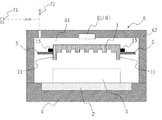
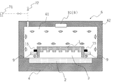
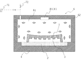
- the imprinting apparatus of the present invention pressurizes the object 3 to be molded by the mold 1 and the substrate 2, and transfers the molding pattern of the mold 1 to the object 3 to be molded. It is mainly composed of a stage 4, an arrangement means 5, a pressure adjusting unit 6, a depressurizing means 71, a pressurizing means 72, and a fixing means 8.
- the mold 1 used in the imprinting apparatus and the imprinting method of the present invention is preferably made of a rigid body so that the molding pattern is not distorted.
- a resin such as PET or COP or an inorganic material such as glass may be used.
- a transparent material is selected when the light source is placed on the mold 1 side.
- a material having heat resistance to the operating temperature is selected.
- the molding pattern includes not only a geometric shape composed of irregularities but also a pattern for transferring a predetermined surface state such as a transfer of a mirror surface state having a predetermined surface roughness. Further, the molding pattern is formed into various sizes such that the width of the convex portion and the minimum width of the concave portion are 100 ⁇ m or less, 10 ⁇ m or less, 2 ⁇ m or less, 1 ⁇ m or less, 100 nm or less, and 10 nm or less. Further, the dimensions in the depth direction are also formed into various sizes such as 10 nm or more, 100 nm or more, 200 nm or more, 500 nm or more, 1 ⁇ m or more, 10 ⁇ m or more, 100 ⁇ m or more.
- the mold 1 may have a wall portion 11 that surrounds the periphery of the molding pattern. As a result, it is possible to prevent the object 3 to be molded from leaking toward the side surface of the mold 1 when the object 3 to be molded is pressed by the mold 1, and the object 3 to be molded can be sufficiently filled in the molding pattern.
- the height of the wall portion 11 with respect to the surface having the molding pattern may be, for example, 1 ⁇ m or more.
- the height of the wall portion varies, the parallelism between the mold and the substrate is disturbed by the pressurization because the degree of flow of the object to be molded in the vicinity of the wall portion differs in the pressurizing step of the imprint method described later. .. Therefore, it is preferable that the height variation of the wall portion is small. For example, it is preferable that the difference between the maximum value and the minimum value of the height of the wall portion with respect to the surface having the molding pattern is 1 ⁇ m or less.
- the substrate 2 may be any material as long as it can support the object 3 to be molded, and for example, a resin, an inorganic compound, a metal, or the like can be used.
- the object 3 to be molded is one to which the molding pattern of the mold 1 is transferred, and may be held by at least one of the mold 1 and the substrate 2.
- the resin used for the object 3 include a photocurable resin, a thermosetting resin, and a thermoplastic resin.
- the photocurable resin used for the object 3 to be molded is a fluid resin that is cured by light of a specific wavelength, and any photocurable resin used in the optical imprint technology can be used.
- silicone rubber such as polydimethylsiloxane (PDMS), epoxide-containing compounds, (meth) acrylic acid ester compounds, vinyl ether compounds, and bisallyl nadiimide compounds are unsaturated such as vinyl group and allyl group.
- Hydrocarbon group-containing compounds and the like can be used.
- a photoreactive initiator may be added to allow the polymerization reaction to proceed by light irradiation to form a molding pattern.
- an acetophenone derivative, a benzophenone derivative, a benzoin ether derivative, a xanthone derivative and the like can be preferably used.
- the reactive monomer may be used without a solvent, or may be used by dissolving it in a solvent and removing the solvent after coating.
- thermosetting resin used for the object 3 to be molded is a fluid resin that cures when heated, and any thermosetting resin used in the thermal imprinting technique can be used.
- silicone rubber such as polydimethylsiloxane (PDMS), epoxide-containing compounds, (meth) acrylic acid ester compounds, vinyl ether compounds, and bisallyl nadiimide compounds are unsaturated such as vinyl group and allyl group.
- Hydrocarbon group-containing compounds and the like can be used.
- Organic peroxides and azo compounds can be preferably used as the heat-reactive radical initiator, and acetophenone derivatives, benzophenone derivatives, benzoin ether derivatives, xantone derivatives and the like can be preferably used as the photoreactive radical initiators.
- the reactive monomer may be used without a solvent, or may be used by dissolving it in a solvent and removing the solvent after coating.
- the thermoplastic resin used for the object 3 to be molded is a resin that has fluidity when it reaches the glass transition temperature or melting point and solidifies when cooled, and is any kind as long as it is used for thermal imprinting technology. Can also be used.
- cyclic olefin resins such as cyclic olefin ring-opening polymerization / hydrogenated products (COP) and cyclic olefin copolymers (COC), acrylic resins, polycarbonates, vinyl ether resins, perfluoroalkoxy alkanes (PFA) and polytetrafluoroethylene.
- Fluororesin such as (PTFE), polystyrene, polyimide resin, polyester resin and the like can be used.
- the stage 4 is for mounting either the mold 1 or the substrate 2. It is preferable that the mold 1 and the substrate 2 can be placed so as to be parallel to each other, and preferably, the surface having the molding pattern of the mold 1 and the surface on the opposite side of the substrate 2 can be placed so as to be horizontal. ..
- the material of the stage 4 may be any material as long as it meets the molding conditions. For example, it is preferable to use a material having pressure resistance, heat resistance, etc. with respect to the molding conditions, and a metal such as stainless steel. Can be used. Further, in the optical imprint process, when the light source is arranged on the stage 4 side, a transparent material such as glass may be used.
- the arranging means 5 is located on the stage 4 of the mold 1 and the substrate 2 at a position where the mold 1 and the substrate 2 sandwich the object 3 to be molded and at a position where the mold 1 and the substrate 2 can freely move in a direction close to each other.
- the one that is not placed is placed.
- the mold 1 and the substrate 2 sandwich the object 3 to be molded means a state in which the object 3 to be molded is in contact with both the mold 1 and the substrate 2.
- the mold 1 and the substrate 2 can be freely moved in a direction close to each other means that the mold 1 or the substrate 2 is substantially placed on the fluid object 3 to be molded. It is floating and means a state in which the entire mold 1 or substrate 2 can receive uniform pressure.
- the mold 1 when the substrate 2 is placed on the stage 4, the mold 1 is arranged at a position where the mold 1 and the substrate 2 can freely move in a direction close to each other. That is, the mold 1 is placed on the object 3 to be molded on the substrate 2 and is in a substantially floating state.
- the substrate 2 when the mold 1 is placed on the stage 4, the substrate 2 is arranged at a position where the mold 1 and the substrate 2 can freely move in a direction close to each other. That is, the substrate 2 is placed on the object 3 to be molded on the mold 1 and is in a substantially floating state.
- the arrangement means 5 is preferably one that can be arranged so that the mold 1 and the substrate 2 are parallel to each other.
- the arranging means 5 arranges either the mold 1 or the substrate 2 at a position where the mold 1 and the substrate 2 sandwich the object 3 to be molded and at a position where the mold 1 and the substrate 2 can freely move in a direction close to each other. Anything can be used as long as it can be used, but for example, a holding portion for horizontally holding the mold 1 or the substrate 2, an elevating means for raising and lowering the holding portion, and a holding portion are laterally separated from the mold 1. It may be composed of a separating means.
- a protruding portion 15 that protrudes horizontally may be provided on the side surface of the mold 1 so that the protruding portion 15 can be mounted.
- the holding portion may be moved by the elevating means or the separating means by using a well-known one such as one that is moved by a hydraulic or pneumatic cylinder or one that is moved by an electric motor and a ball screw.
- the arranging means 5 may have a position detecting means for detecting the relative position of the mold 1 with respect to the substrate 2.
- a position detecting means for detecting the relative position of the mold 1 with respect to the substrate 2.
- the position detecting means a well-known one may be used.
- a laser length measuring machine provided on the stage 4 may be used to measure the position of the mold 1.
- the position of the mold 1 may be measured by calculating from the displacement amount by using the encoder provided in the electric motor.
- the pressure adjusting unit 6 constitutes a pressure adjusting chamber 61 capable of containing the mold 1 and the substrate 2. Thereby, by adjusting the air pressure in the pressure adjusting chamber 61, it is possible to suppress the gas from remaining in the molding pattern of the mold 1 and to pressurize the object 3 to be molded by the mold 1 and the substrate 2.
- the pressure adjusting chamber 61 may have any size and shape as long as it can include the mold 1 and the substrate 2, and may be designed in consideration of the air pressure in the pressure adjusting chamber 61, the adjustment time, and the like.
- a bottomed tubular housing 62 that constitutes the pressure regulating chamber 61 together with the stage 4 can be used.
- a means for raising and lowering the housing 62 with respect to the stage 4 is provided so as to open the space between the housing 62 and the stage 4.
- the housing 62 may be provided with an opening / closing portion for transporting the mold 1 and the substrate 2 into the pressure regulating chamber 61.
- the pressure adjusting unit 6 may be configured to have a pressure adjusting chamber 61 including the stage 4.
- the depressurizing means 71 is for removing the gas between the mold 1 and the object to be molded 3 and depressurizing the inside of the pressure regulating chamber 61 to a pressure at which there is no problem in forming the pattern.
- the pressure at which there is no problem in forming the pattern means a pressure that can prevent gas from remaining as bubbles in the molding pattern and causing transfer defects, and is, for example, 1000 Pa or less, preferably 100 Pa or less.
- a well-known decompression pump connected to the pressure adjusting chamber 61 and capable of removing the gas in the pressure adjusting chamber 61 may be used.
- the pressurizing means 72 is for pressurizing the inside of the pressure adjusting chamber 61 in order to fill the molding pattern of the mold 1 with the object 3 to be molded.
- the pressure at which the object to be molded 3 can be filled into the molding pattern of the mold 1 is appropriately set depending on the viscosity of the object to be molded 3 and the like.
- the pressurizing means 72 pressurizes the inside of the pressure adjusting chamber 61 within a range in which the mold 1 and the substrate 2 can freely move in a direction close to each other. As a result, uniform pressure can be applied to the mold 1, the substrate 2, and the object 3 to be molded, so that it is possible to prevent the object 3 to be distorted.
- the pressurizing means 72 for example, a cylinder connected to the pressure regulating chamber 61 and supplying a gas such as air or an inert gas that can pressurize the inside of the pressure regulating chamber 61, or a pressurizing pump can be used. Further, when the pressure to be pressurized is sufficient at atmospheric pressure, as shown in FIG. 4, an open valve connecting the inside of the pressure adjusting chamber 61 and the outside of the pressure adjusting chamber 61 may be used.
- the mold 1 or the substrate 2 is arranged at a position where the mold 1 and the substrate 2 sandwich the object 2 to be molded by the arranging means 5, and at a position where the mold 1 and the substrate 2 can freely move in a direction in which the mold 1 and the substrate 2 are close to each other.
- the pressurizing means 72 can pressurize the mold 1 and the object to be molded 3 within a range in which the mold 1 and the substrate 2 can freely move in a direction close to each other.
- the control means may be any means as long as it can control the arrangement means 5 and the pressure adjusting means 7, and a well-known computer can be used.
- the fixing means 8 is for fixing the object to be molded 3 to the molding pattern.
- the fixing means 8 is used for optical imprinting
- the light irradiation means 81 may be used.
- a temperature control means may be used.
- the light irradiation means 81 is for irradiating a molded object 3 made of a photocurable resin with light to solidify it.
- the light irradiation means 81 may be any one as long as it can irradiate the object 3 to be molded with an electromagnetic wave having a predetermined wavelength and cure it.
- an ultraviolet irradiation device for irradiating the object 3 with ultraviolet rays is used. Good.
- the light irradiation means 8 may be singular or plural as long as it can irradiate the object 3 to be molded. When a plurality of them are arranged, it is preferable to arrange them so that the illuminance distribution is as uniform as possible in the object 3 to be molded.
- the temperature control means is for adjusting the temperature of the object to be molded 3 made of a thermosetting resin or a thermoplastic resin to make the object to be molded 3 fluid or solidify.
- a heating means for directly or indirectly heating the object 3 to be molded can be used.
- a cooling means for directly or indirectly cooling the object 3 to be molded can also be used.
- the heating means heats either or both of the mold 1 and the object 3 to a predetermined temperature, for example, the glass transition temperature or the melting point of the thermoplastic resin constituting the object 3, or the curing temperature of the thermosetting resin or more. Anything that can be heated to is used.
- the object 3 to be molded may be heated from the stage 4 side or from the mold 1 side.
- a heater provided in the stage 4 to heat the mold 1 and the object to be molded 3 can be used. It is also possible to heat using a heated liquid or gas.
- the cooling means cools either or both of the mold 1 and the object to be molded at a predetermined temperature, for example, below the glass transition temperature or melting point of the thermoplastic resin constituting the object to be molded 3, or below the curing temperature of the thermosetting resin. Anything that can be cooled to is used.
- the object 3 to be molded may be cooled from the stage 4 side or from the mold 1 side.
- a cooling fan or a cooling water channel formed in the stage 4 to cool the mold 1 and the object 3 to be molded by flowing a liquid can be used.
- the temperature controlling means includes a temperature detecting means for detecting the temperature of the mold 1, the substrate 2, the object 3 to be molded, the stage 4, etc., and even if the temperature of the object 3 to be molded is adjusted based on the detected temperature information. Good.
- one of the mold 1 and the substrate 2 is floating on the object 3 to be molded at a position where the mold 1 and the substrate 2 can freely move in a direction close to each other. Therefore, there is a problem that the mold 1 and the substrate 2 are easily slid and moved when the mold 1 and the substrate 2 are pressurized. Therefore, a slide preventing means 9 for preventing the slide movement of the mold 1 and the substrate 2 may be provided.
- the slide preventing means 9 may be any device as long as it can prevent the slide movement in the direction orthogonal to the proximity direction without hindering the movement of the mold 1 or the substrate 2 floating on the object 3 in the proximity direction. For example, as shown in FIG.
- a guide-shaped slide preventing means 9 may be provided on the side surface of the mold 1 floating on the object 3 to be molded with a predetermined gap.
- a guide-shaped slide preventing means which is not shown, may be provided on the side surface of the substrate 2 with a predetermined gap.
- the arrangement means 5 may be used as the slide prevention means.
- the arranging means 5 may be formed so as to be movable at a position where the mold 1 and the substrate 2 are prevented from sliding when the mold 1 and the object 3 to be molded are pressurized.
- the size of the gap between the slide preventing means 9 and the side surface of the mold 1 or the substrate 2 is not particularly limited as long as the slide movement of the mold 1 and the substrate 2 can be tolerated, but the size is, for example, 0.5 mm or less. Just do it.
- the imprint method of the present invention is a method for pressurizing the object 3 to be molded by the mold 1 and the substrate 2 to transfer the molding pattern of the mold 1 to the object 3 to be molded, and includes a decompression step and an arrangement step. It is mainly composed of a pressurizing process and a fixing process.
- the decompression process is for removing the gas between the mold and the object to be molded.
- the pressure inside the pressure adjusting chamber 61 may be reduced by leaving a space between the mold 1 and the object to be molded 3, and the gas in the pressure adjusting chamber 61 may be removed. This makes it possible to prevent the gas from remaining as bubbles in the molding pattern and causing transfer defects.
- the pressure in the pressure reducing step is not particularly limited as long as the pressure inside the pressure regulating chamber 61 can be reduced to a pressure at which there is no problem in forming the pattern, but for example, 1000 Pa or less, preferably 100 Pa or less is preferable.
- the object to be molded 3 is sandwiched between the mold 1 and the substrate 2 so that the mold 1 and the substrate 2 can be freely moved in the adjacent direction.
- the mold 1 and the substrate 3 are arranged. Specifically, as shown in FIG. 2, when the substrate 2 is placed on the stage 4, the mold 1 is arranged at a position where the mold 1 and the substrate 2 can freely move in a direction close to each other. That is, the mold 1 is placed on the object 3 to be molded on the substrate 2 and is in a substantially floating state. Further, as shown in FIG.
- the substrate 2 when the mold 1 is placed on the stage 4, the substrate 2 is arranged at a position where the mold 1 and the substrate 2 can freely move in a direction close to each other. That is, the substrate 2 is placed on the object 3 to be molded on the mold 1 and is in a substantially floating state. In the arrangement step, it is preferable to arrange the mold 1 and the substrate 2 so as to be parallel to each other.
- the pressurizing step is to pressurize the mold 1 and the object to be molded 3 with a gas within a range in which the mold 1 and the substrate 2 can freely move in a direction close to each other. As a result, uniform pressure can be applied to the mold 1, the substrate 2, and the object 3 to be molded, so that it is possible to prevent the object 3 to be distorted.
- one of the mold 1 and the substrate 2 is floating on the object 3 to be molded at a position where the mold 1 and the substrate 2 can freely move in a direction close to each other. Therefore, the mold 1 and the substrate 2 can easily slide and move when the mold 1 and the substrate 2 are pressurized. Therefore, it is preferable that the pressurizing step is performed while preventing the slide movement of the mold 1 and the substrate 2 (see FIG. 4 or FIG. 5).
- the fixing step is to fix the object 3 to be molded on the molding pattern.
- a fixing step in the case of optical imprinting, as shown in FIG. 6, the object to be molded 3 made of a photocurable resin may be irradiated with light to be solidified, and the molding pattern may be fixed to the object to be molded 3. .
- the light to be irradiated may be any light as long as it can cure the photocurable resin used for the object to be molded 3, and for example, ultraviolet rays can be used.
- the temperature of the object to be molded 3 may be adjusted to solidify and the molding pattern may be fixed to the object to be molded 3.
- the object to be molded 3 when the object to be molded 3 is made of a thermosetting resin, the object to be molded 3 may be heated to a temperature higher than the temperature at which the resin is cured to solidify. When the object to be molded 3 is made of a thermoplastic resin, the object to be molded 3 may be cooled and solidified below the glass transition temperature or the melting point of the resin.
- a temperature control step of adjusting the temperature so that the object 3 to be molded has fluidity may be required before the pressurization step.
- the object to be molded 3 is made of a thermoplastic resin
- the object to be molded 3 is heated to a temperature equal to or higher than the glass transition temperature or melting point of the resin.
- the temperature of the object 3 is maintained below the temperature at which the resin does not cure.
- the temperature control step may be performed before or after the depressurization step.
- the object 3 to be molded can be formed by transferring the molding pattern of the mold 1 without distortion.
Landscapes
- Physics & Mathematics (AREA)
- General Physics & Mathematics (AREA)
- Engineering & Computer Science (AREA)
- Mechanical Engineering (AREA)
- Microelectronics & Electronic Packaging (AREA)
- Shaping Of Tube Ends By Bending Or Straightening (AREA)
- Exposure Of Semiconductors, Excluding Electron Or Ion Beam Exposure (AREA)
- Micromachines (AREA)
- Auxiliary Devices For And Details Of Packaging Control (AREA)
- Camera Data Copying Or Recording (AREA)
Abstract
Description
2 基板
3 被成形物
4 ステージ
5 配置手段
6 調圧部
7 調圧手段
8 定着手段
9 スライド防止手段
11 壁部
15 突出部
61 調圧室
62 筐体
71 減圧手段
72 加圧手段
81 光照射手段
Claims (17)
- 被成形物をモールドと基板で加圧して、前記モールドの成型パターンを前記被成形物に転写するためのインプリント装置であって、
前記モールド又は前記基板のいずれか一方を載置するためのステージと、
前記被成形物を前記モールドと前記基板が挟む位置であると共に、前記モールドと前記基板が近接する方向に自由に移動可能な位置に、前記モールドと前記基板のうち前記ステージに載置されていない方を配置する配置手段と、
前記モールドと前記基板を内包可能な調圧室を有する調圧部と、
前記調圧室内を減圧する減圧手段と、
前記モールドと前記基板が近接する方向に自由に移動可能な範囲で、前記調圧室内を加圧する加圧手段と、
前記被成形物を前記成型パターンに定着させるための定着手段と、
を具備することを特徴とするインプリント装置。 - 前記モールドと前記基板のスライド移動を防止するスライド防止手段を具備することを特徴とする請求項1記載のインプリント装置。
- 前記配置手段は、前記モールドと前記基板のスライド移動を防止する位置に移動可能であることを特徴とする請求項1記載のインプリント装置。
- 前記配置手段は、前記基板に対する前記モールドの相対的な位置を検出する位置検出手段を有することを特徴とする請求項1ないし3のいずれかに記載のインプリント装置。
- 前記位置検出手段の検出情報に基づいて、前記配置手段又は前記調圧手段の少なくともいずれか一方を制御する制御手段を具備することを特徴とする請求項4記載のインプリント装置。
- 前記配置手段は、前記モールドと前記基板が平行となるように配置するものであることを特徴とする請求項1ないし5のいずれかに記載のインプリント装置。
- 前記成型パターンの周囲を囲む壁部を有するモールドを具備することを特徴とする請求項1ないし6のいずれかに記載のインプリント装置。
- 前記成型パターンを有する面に対する前記壁部の高さは、1μm以上であることを特徴とする請求項7記載のインプリント装置。
- 前記成型パターンを有する面に対する前記壁部の高さの最大値と最小値の差は、1μm以下であることを特徴とする請求項7又は8記載のインプリント装置。
- 前記定着手段は、前記被成形物に光を照射して固化させるための光照射手段、又は前記被成形物の温度を調節する温調手段であることを特徴とする請求項1ないし9のいずれかに記載のインプリント装置。
- 被成形物をモールドと基板で加圧して、前記モールドの成型パターンを前記被成形物に転写するためのインプリント方法であって、
前記モールドと被成形物の間の気体を除去する減圧工程と、
減圧化において、前記被成形物を間に挟んだ状態であって前記モールドと前記基板が近接する方向に自由に移動可能な位置に、前記モールドと前記基板を配置する配置工程と、
前記モールドと前記基板が近接する方向に自由に移動可能な範囲で、前記モールドと前記被成形物を気体で加圧する加圧工程と、
前記被成形物を前記成型パターンに定着させる定着工程と、
を有することを特徴とするインプリント方法。 - 前記加圧工程は、前記モールドと前記基板のスライド移動を防止しながら行うことを特徴とする請求項11記載のインプリント方法。
- 前記配置工程は、前記モールドと前記基板が平行となるように配置することを特徴とする請求項11又は12記載のインプリント装置。
- 前記定着工程は、前記被成形物に光を照射して固化させ、当該被成形物に前記成型パターンを定着させる工程、又は前記被成形物の温度を調節して固化させ、当該被成形物に前記成型パターンを定着させる工程であることを特徴とする請求項11ないし13のいずれかに記載のインプリント方法。
- 前記モールドは、前記成型パターンの周囲を囲む壁部を有することを特徴とする請求項11ないし14のいずれかに記載のインプリント方法。
- 前記成型パターンを有する面に対する前記壁部の高さは、1μm以上であることを特徴とする請求項15記載のインプリント方法。
- 前記成型パターンを有する面に対する前記壁部の高さの最大値と最小値の差は、1μm以下であることを特徴とする請求項15又は16記載のインプリント方法。
Priority Applications (10)
| Application Number | Priority Date | Filing Date | Title |
|---|---|---|---|
| CN202511239338.7A CN120742616A (zh) | 2019-12-25 | 2020-12-21 | 使用印模的传送方法以及印模的应用 |
| EP20906694.3A EP4084044A4 (en) | 2019-12-25 | 2020-12-21 | PRINTING DEVICE AND PRINTING METHOD |
| IL293816A IL293816B2 (en) | 2019-12-25 | 2020-12-21 | Embedding device and embedding method |
| JP2021567434A JP7335978B2 (ja) | 2019-12-25 | 2020-12-21 | インプリント装置およびインプリント方法 |
| IL318240A IL318240A (en) | 2019-12-25 | 2020-12-21 | Imprinting Device and Imprinting Method |
| CN202080089804.7A CN114868228B (zh) | 2019-12-25 | 2020-12-21 | 压印装置、压印方法及传送方法 |
| KR1020257016167A KR20250078587A (ko) | 2019-12-25 | 2020-12-21 | 임프린트 장치 및 임프린트 방법 |
| KR1020227021564A KR20220120579A (ko) | 2019-12-25 | 2020-12-21 | 임프린트 장치 및 임프린트 방법 |
| US17/849,575 US12422745B2 (en) | 2019-12-25 | 2022-06-24 | Imprint device and imprint method |
| US18/979,490 US20250110398A1 (en) | 2019-12-25 | 2024-12-12 | Imprint Device and Imprint Method |
Applications Claiming Priority (2)
| Application Number | Priority Date | Filing Date | Title |
|---|---|---|---|
| JP2019-234816 | 2019-12-25 | ||
| JP2019234816 | 2019-12-25 |
Related Child Applications (1)
| Application Number | Title | Priority Date | Filing Date |
|---|---|---|---|
| US17/849,575 Continuation-In-Part US12422745B2 (en) | 2019-12-25 | 2022-06-24 | Imprint device and imprint method |
Publications (1)
| Publication Number | Publication Date |
|---|---|
| WO2021132142A1 true WO2021132142A1 (ja) | 2021-07-01 |
Family
ID=76574700
Family Applications (1)
| Application Number | Title | Priority Date | Filing Date |
|---|---|---|---|
| PCT/JP2020/047648 Ceased WO2021132142A1 (ja) | 2019-12-25 | 2020-12-21 | インプリント装置およびインプリント方法 |
Country Status (7)
| Country | Link |
|---|---|
| US (2) | US12422745B2 (ja) |
| EP (1) | EP4084044A4 (ja) |
| JP (5) | JP7335978B2 (ja) |
| KR (2) | KR20220120579A (ja) |
| CN (2) | CN114868228B (ja) |
| IL (2) | IL293816B2 (ja) |
| WO (1) | WO2021132142A1 (ja) |
Cited By (1)
| Publication number | Priority date | Publication date | Assignee | Title |
|---|---|---|---|---|
| CN114683463A (zh) * | 2022-03-28 | 2022-07-01 | 业成科技(成都)有限公司 | 光波导治具及光波导的制备方法 |
Families Citing this family (2)
| Publication number | Priority date | Publication date | Assignee | Title |
|---|---|---|---|---|
| US20240264524A1 (en) * | 2023-02-08 | 2024-08-08 | Asmpt Singapore Pte. Ltd. | Combined dispensing and stamping apparatus and method for applying adhesive fluid during a bonding process |
| CN120176900B (zh) * | 2025-03-12 | 2025-11-14 | 江门市新会区先锋五金制品有限公司 | 用于检测锅底压花设备运行状态的方法和设备 |
Citations (9)
| Publication number | Priority date | Publication date | Assignee | Title |
|---|---|---|---|---|
| US5947027A (en) * | 1998-09-08 | 1999-09-07 | Motorola, Inc. | Printing apparatus with inflatable means for advancing a substrate towards the stamping surface |
| US6190929B1 (en) * | 1999-07-23 | 2001-02-20 | Micron Technology, Inc. | Methods of forming semiconductor devices and methods of forming field emission displays |
| JP2004504718A (ja) * | 2000-07-18 | 2004-02-12 | ナノネックス コーポレーション | 流体圧力インプリント・リソグラフィ |
| WO2004062886A1 (ja) | 2003-01-15 | 2004-07-29 | Scivax Corporation | パターン形成装置、パターン形成方法、パターン形成システム |
| WO2007105474A1 (ja) * | 2006-03-10 | 2007-09-20 | Pioneer Corporation | インプリント方法及びインプリント装置 |
| WO2008088068A1 (ja) | 2007-01-19 | 2008-07-24 | The University Of Tokyo | 微小構造体の製造方法,微小構造体およびマイクロデバイス |
| JP2008221706A (ja) * | 2007-03-14 | 2008-09-25 | Toshiba Mach Co Ltd | 転写装置および転写方法 |
| JP2008246944A (ja) * | 2007-03-30 | 2008-10-16 | Hitachi Industrial Equipment Systems Co Ltd | 微細パターン転写用金型およびそれを用いた樹脂製転写物の製造方法 |
| WO2015186736A1 (ja) * | 2014-06-03 | 2015-12-10 | Scivax株式会社 | ローラ式加圧装置、インプリント装置およびローラ式加圧方法 |
Family Cites Families (28)
| Publication number | Priority date | Publication date | Assignee | Title |
|---|---|---|---|---|
| US5937758A (en) | 1997-11-26 | 1999-08-17 | Motorola, Inc. | Micro-contact printing stamp |
| KR100827741B1 (ko) * | 2000-07-17 | 2008-05-07 | 보드 오브 리전츠, 더 유니버시티 오브 텍사스 시스템 | 임프린트 리소그래피 공정을 위한 자동 유체 분배 방법 및시스템 |
| US7686970B2 (en) * | 2004-12-30 | 2010-03-30 | Asml Netherlands B.V. | Imprint lithography |
| JP2007194304A (ja) * | 2006-01-18 | 2007-08-02 | Hitachi Ltd | インプリント装置およびインプリント方法 |
| JP4854383B2 (ja) * | 2006-05-15 | 2012-01-18 | アピックヤマダ株式会社 | インプリント方法およびナノ・インプリント装置 |
| KR100913497B1 (ko) * | 2007-12-27 | 2009-08-25 | 한국산업기술대학교산학협력단 | 임프린팅 장치 및 임프린팅 방법 |
| JP5279397B2 (ja) * | 2008-08-06 | 2013-09-04 | キヤノン株式会社 | インプリント装置、インプリント方法、およびデバイス製造方法 |
| JP5296641B2 (ja) * | 2009-09-02 | 2013-09-25 | 東京エレクトロン株式会社 | インプリント方法、プログラム、コンピュータ記憶媒体及びインプリント装置 |
| US8771933B2 (en) * | 2009-10-06 | 2014-07-08 | Massachusetts Institute Of Technology | Continuous-flow deformability-based cell separation |
| US8747092B2 (en) * | 2010-01-22 | 2014-06-10 | Nanonex Corporation | Fast nanoimprinting apparatus using deformale mold |
| JP2011199136A (ja) | 2010-03-23 | 2011-10-06 | Toppan Printing Co Ltd | インプリント用モールド及びその作製方法並びにパターン転写体 |
| KR101323235B1 (ko) * | 2010-06-07 | 2013-10-30 | 엘지디스플레이 주식회사 | 임프린팅 장치 및 이를 이용한 임프린팅 방법 |
| KR101780487B1 (ko) * | 2010-07-19 | 2017-09-22 | 엘지디스플레이 주식회사 | 임프린팅 장치 및 이를 이용한 임프린팅 방법 |
| JP2012049370A (ja) * | 2010-08-27 | 2012-03-08 | Toshiba Corp | インプリント装置 |
| JP5488766B2 (ja) * | 2011-06-02 | 2014-05-14 | Scivax株式会社 | 流体圧インプリント装置およびインプリント方法 |
| JP5970646B2 (ja) | 2011-11-25 | 2016-08-17 | Scivax株式会社 | インプリント装置およびインプリント方法 |
| KR101515180B1 (ko) * | 2012-05-18 | 2015-04-24 | 주식회사 휴템 | 유체압을 이용한 기판접합 장치 및 기판접합 방법 |
| JP5949430B2 (ja) | 2012-10-18 | 2016-07-06 | 富士通株式会社 | インプリント装置及びインプリント方法 |
| JP2014175620A (ja) * | 2013-03-12 | 2014-09-22 | Canon Inc | インプリント装置、型セット、インプリント方法、および、物品の製造方法 |
| JP6494185B2 (ja) | 2013-06-26 | 2019-04-03 | キヤノン株式会社 | インプリント方法および装置 |
| JP6437387B2 (ja) | 2015-05-25 | 2018-12-12 | 東芝メモリ株式会社 | 基板平坦化方法 |
| JP2016225433A (ja) | 2015-05-29 | 2016-12-28 | キヤノン株式会社 | モールド、インプリント方法、インプリント装置および物品の製造方法 |
| JP6677495B2 (ja) | 2015-12-04 | 2020-04-08 | キヤノン株式会社 | インプリント装置、及び物品の製造方法 |
| JP6042002B1 (ja) * | 2016-01-26 | 2016-12-14 | 綜研化学株式会社 | 構造体 |
| KR102256347B1 (ko) * | 2017-03-08 | 2021-05-27 | 캐논 가부시끼가이샤 | 패턴 형성 방법, 및 가공 기판, 광학 부품 및 석영 몰드 레플리카의 제조 방법, 및 임프린트 전처리 코팅 재료 및 그와 임프린트 레지스트와의 세트 |
| JP6978859B2 (ja) * | 2017-06-15 | 2021-12-08 | キヤノン株式会社 | インプリント装置、および物品の製造方法 |
| JP2019212862A (ja) * | 2018-06-08 | 2019-12-12 | キヤノン株式会社 | モールド、平面プレート、インプリント方法、および物品製造方法 |
| JP7348182B2 (ja) * | 2018-07-23 | 2023-09-20 | 株式会社日立ハイテク | 凹面回折格子の製造方法、製造装置及び凹面回折格子 |
-
2020
- 2020-12-21 WO PCT/JP2020/047648 patent/WO2021132142A1/ja not_active Ceased
- 2020-12-21 IL IL293816A patent/IL293816B2/en unknown
- 2020-12-21 IL IL318240A patent/IL318240A/en unknown
- 2020-12-21 KR KR1020227021564A patent/KR20220120579A/ko active Pending
- 2020-12-21 CN CN202080089804.7A patent/CN114868228B/zh active Active
- 2020-12-21 EP EP20906694.3A patent/EP4084044A4/en active Pending
- 2020-12-21 JP JP2021567434A patent/JP7335978B2/ja active Active
- 2020-12-21 KR KR1020257016167A patent/KR20250078587A/ko active Pending
- 2020-12-21 CN CN202511239338.7A patent/CN120742616A/zh active Pending
-
2022
- 2022-06-24 US US17/849,575 patent/US12422745B2/en active Active
-
2023
- 2023-06-02 JP JP2023091978A patent/JP7557009B2/ja active Active
- 2023-06-02 JP JP2023091977A patent/JP7556096B2/ja active Active
-
2024
- 2024-09-12 JP JP2024158564A patent/JP2025003440A/ja active Pending
- 2024-12-12 US US18/979,490 patent/US20250110398A1/en active Pending
-
2025
- 2025-12-26 JP JP2025284712A patent/JP2026053678A/ja active Pending
Patent Citations (9)
| Publication number | Priority date | Publication date | Assignee | Title |
|---|---|---|---|---|
| US5947027A (en) * | 1998-09-08 | 1999-09-07 | Motorola, Inc. | Printing apparatus with inflatable means for advancing a substrate towards the stamping surface |
| US6190929B1 (en) * | 1999-07-23 | 2001-02-20 | Micron Technology, Inc. | Methods of forming semiconductor devices and methods of forming field emission displays |
| JP2004504718A (ja) * | 2000-07-18 | 2004-02-12 | ナノネックス コーポレーション | 流体圧力インプリント・リソグラフィ |
| WO2004062886A1 (ja) | 2003-01-15 | 2004-07-29 | Scivax Corporation | パターン形成装置、パターン形成方法、パターン形成システム |
| WO2007105474A1 (ja) * | 2006-03-10 | 2007-09-20 | Pioneer Corporation | インプリント方法及びインプリント装置 |
| WO2008088068A1 (ja) | 2007-01-19 | 2008-07-24 | The University Of Tokyo | 微小構造体の製造方法,微小構造体およびマイクロデバイス |
| JP2008221706A (ja) * | 2007-03-14 | 2008-09-25 | Toshiba Mach Co Ltd | 転写装置および転写方法 |
| JP2008246944A (ja) * | 2007-03-30 | 2008-10-16 | Hitachi Industrial Equipment Systems Co Ltd | 微細パターン転写用金型およびそれを用いた樹脂製転写物の製造方法 |
| WO2015186736A1 (ja) * | 2014-06-03 | 2015-12-10 | Scivax株式会社 | ローラ式加圧装置、インプリント装置およびローラ式加圧方法 |
Non-Patent Citations (1)
| Title |
|---|
| See also references of EP4084044A4 |
Cited By (1)
| Publication number | Priority date | Publication date | Assignee | Title |
|---|---|---|---|---|
| CN114683463A (zh) * | 2022-03-28 | 2022-07-01 | 业成科技(成都)有限公司 | 光波导治具及光波导的制备方法 |
Also Published As
| Publication number | Publication date |
|---|---|
| JP7557009B2 (ja) | 2024-09-26 |
| EP4084044A1 (en) | 2022-11-02 |
| CN114868228B (zh) | 2026-04-28 |
| JP7335978B2 (ja) | 2023-08-30 |
| JP2023107840A (ja) | 2023-08-03 |
| US20220317568A1 (en) | 2022-10-06 |
| KR20220120579A (ko) | 2022-08-30 |
| CN114868228A (zh) | 2022-08-05 |
| JPWO2021132142A1 (ja) | 2021-07-01 |
| JP2025003440A (ja) | 2025-01-09 |
| KR20250078587A (ko) | 2025-06-02 |
| CN120742616A (zh) | 2025-10-03 |
| JP2023107839A (ja) | 2023-08-03 |
| IL318240A (en) | 2025-03-01 |
| JP7556096B2 (ja) | 2024-09-25 |
| IL293816B2 (en) | 2026-03-01 |
| EP4084044A4 (en) | 2024-06-05 |
| US12422745B2 (en) | 2025-09-23 |
| IL293816B1 (en) | 2025-11-01 |
| JP2026053678A (ja) | 2026-03-25 |
| US20250110398A1 (en) | 2025-04-03 |
| IL293816A (en) | 2022-08-01 |
Similar Documents
| Publication | Publication Date | Title |
|---|---|---|
| JP7556096B2 (ja) | スタンプ | |
| JP6330157B2 (ja) | インプリント用型を用いたインプリント方法 | |
| JP5644014B2 (ja) | ローラ式加圧装置、インプリント装置、ローラ式加圧方法 | |
| JP6592659B2 (ja) | ローラ式加圧装置、インプリント装置およびローラ式加圧方法 | |
| WO2013105658A1 (ja) | 成形方法及び成形装置 | |
| WO2013077386A1 (ja) | インプリント装置およびインプリント方法 | |
| JP6291687B2 (ja) | インプリント装置およびインプリント方法 | |
| JP5488766B2 (ja) | 流体圧インプリント装置およびインプリント方法 | |
| JPWO2012147958A1 (ja) | 流体圧インプリント装置および加圧装置 | |
| JP5499306B2 (ja) | 加圧部用固定具を備えた流体圧インプリント装置 | |
| WO2013035759A1 (ja) | 剛体ステージを備えた流体圧インプリント装置及び加圧ステージ | |
| WO2021182532A1 (ja) | インプリント装置 | |
| WO2012096076A1 (ja) | 離型装置、離型方法およびこれらを用いたインプリント装置 |
Legal Events
| Date | Code | Title | Description |
|---|---|---|---|
| 121 | Ep: the epo has been informed by wipo that ep was designated in this application |
Ref document number: 20906694 Country of ref document: EP Kind code of ref document: A1 |
|
| ENP | Entry into the national phase |
Ref document number: 2021567434 Country of ref document: JP Kind code of ref document: A |
|
| NENP | Non-entry into the national phase |
Ref country code: DE |
|
| ENP | Entry into the national phase |
Ref document number: 2020906694 Country of ref document: EP Effective date: 20220725 |
|
| WWP | Wipo information: published in national office |
Ref document number: 1020257016167 Country of ref document: KR |