WO2021132307A1 - 眼科画像処理方法、眼科画像処理装置及び眼科画像処理プログラム - Google Patents
眼科画像処理方法、眼科画像処理装置及び眼科画像処理プログラム Download PDFInfo
- Publication number
- WO2021132307A1 WO2021132307A1 PCT/JP2020/048106 JP2020048106W WO2021132307A1 WO 2021132307 A1 WO2021132307 A1 WO 2021132307A1 JP 2020048106 W JP2020048106 W JP 2020048106W WO 2021132307 A1 WO2021132307 A1 WO 2021132307A1
- Authority
- WO
- WIPO (PCT)
- Prior art keywords
- image
- ophthalmic
- eye
- subsection
- state
- Prior art date
- Legal status (The legal status is an assumption and is not a legal conclusion. Google has not performed a legal analysis and makes no representation as to the accuracy of the status listed.)
- Ceased
Links
Images


Classifications
-
- G—PHYSICS
- G06—COMPUTING OR CALCULATING; COUNTING
- G06T—IMAGE DATA PROCESSING OR GENERATION, IN GENERAL
- G06T7/00—Image analysis
- G06T7/0002—Inspection of images, e.g. flaw detection
- G06T7/0012—Biomedical image inspection
-
- G—PHYSICS
- G06—COMPUTING OR CALCULATING; COUNTING
- G06T—IMAGE DATA PROCESSING OR GENERATION, IN GENERAL
- G06T7/00—Image analysis
- G06T7/10—Segmentation; Edge detection
- G06T7/13—Edge detection
-
- G—PHYSICS
- G06—COMPUTING OR CALCULATING; COUNTING
- G06V—IMAGE OR VIDEO RECOGNITION OR UNDERSTANDING
- G06V10/00—Arrangements for image or video recognition or understanding
- G06V10/40—Extraction of image or video features
- G06V10/44—Local feature extraction by analysis of parts of the pattern, e.g. by detecting edges, contours, loops, corners, strokes or intersections; Connectivity analysis, e.g. of connected components
-
- G—PHYSICS
- G06—COMPUTING OR CALCULATING; COUNTING
- G06V—IMAGE OR VIDEO RECOGNITION OR UNDERSTANDING
- G06V10/00—Arrangements for image or video recognition or understanding
- G06V10/40—Extraction of image or video features
- G06V10/50—Extraction of image or video features by performing operations within image blocks; by using histograms, e.g. histogram of oriented gradients [HoG]; by summing image-intensity values; Projection analysis
-
- G—PHYSICS
- G06—COMPUTING OR CALCULATING; COUNTING
- G06V—IMAGE OR VIDEO RECOGNITION OR UNDERSTANDING
- G06V10/00—Arrangements for image or video recognition or understanding
- G06V10/70—Arrangements for image or video recognition or understanding using pattern recognition or machine learning
- G06V10/77—Processing image or video features in feature spaces; using data integration or data reduction, e.g. principal component analysis [PCA] or independent component analysis [ICA] or self-organising maps [SOM]; Blind source separation
- G06V10/774—Generating sets of training patterns; Bootstrap methods, e.g. bagging or boosting
-
- G—PHYSICS
- G06—COMPUTING OR CALCULATING; COUNTING
- G06V—IMAGE OR VIDEO RECOGNITION OR UNDERSTANDING
- G06V40/00—Recognition of biometric, human-related or animal-related patterns in image or video data
- G06V40/10—Human or animal bodies, e.g. vehicle occupants or pedestrians; Body parts, e.g. hands
- G06V40/18—Eye characteristics, e.g. of the iris
- G06V40/19—Sensors therefor
-
- G—PHYSICS
- G06—COMPUTING OR CALCULATING; COUNTING
- G06V—IMAGE OR VIDEO RECOGNITION OR UNDERSTANDING
- G06V40/00—Recognition of biometric, human-related or animal-related patterns in image or video data
- G06V40/10—Human or animal bodies, e.g. vehicle occupants or pedestrians; Body parts, e.g. hands
- G06V40/18—Eye characteristics, e.g. of the iris
- G06V40/193—Preprocessing; Feature extraction
-
- G—PHYSICS
- G06—COMPUTING OR CALCULATING; COUNTING
- G06V—IMAGE OR VIDEO RECOGNITION OR UNDERSTANDING
- G06V40/00—Recognition of biometric, human-related or animal-related patterns in image or video data
- G06V40/10—Human or animal bodies, e.g. vehicle occupants or pedestrians; Body parts, e.g. hands
- G06V40/18—Eye characteristics, e.g. of the iris
- G06V40/197—Matching; Classification
-
- G—PHYSICS
- G06—COMPUTING OR CALCULATING; COUNTING
- G06T—IMAGE DATA PROCESSING OR GENERATION, IN GENERAL
- G06T2207/00—Indexing scheme for image analysis or image enhancement
- G06T2207/10—Image acquisition modality
- G06T2207/10072—Tomographic images
- G06T2207/10101—Optical tomography; Optical coherence tomography [OCT]
-
- G—PHYSICS
- G06—COMPUTING OR CALCULATING; COUNTING
- G06T—IMAGE DATA PROCESSING OR GENERATION, IN GENERAL
- G06T2207/00—Indexing scheme for image analysis or image enhancement
- G06T2207/20—Special algorithmic details
- G06T2207/20021—Dividing image into blocks, subimages or windows
-
- G—PHYSICS
- G06—COMPUTING OR CALCULATING; COUNTING
- G06T—IMAGE DATA PROCESSING OR GENERATION, IN GENERAL
- G06T2207/00—Indexing scheme for image analysis or image enhancement
- G06T2207/20—Special algorithmic details
- G06T2207/20081—Training; Learning
-
- G—PHYSICS
- G06—COMPUTING OR CALCULATING; COUNTING
- G06T—IMAGE DATA PROCESSING OR GENERATION, IN GENERAL
- G06T2207/00—Indexing scheme for image analysis or image enhancement
- G06T2207/30—Subject of image; Context of image processing
- G06T2207/30004—Biomedical image processing
- G06T2207/30041—Eye; Retina; Ophthalmic
Definitions
- the present invention relates to an ophthalmic image processing method, an ophthalmic image processing apparatus, and an ophthalmic image processing program for analyzing the state of an eye to be inspected.
- Patent Document 1 has been proposed as an ophthalmic apparatus for diagnosing dry eye.
- Patent Document 1 describes a color image of an interference pattern formed in the tear film of the eye to be inspected by illumination light, decomposes the captured color image into a plurality of color components, and bases the signal on each of the decomposed color components. Disclosed by an ophthalmologist who determines the interference fringes appearing in each color component and calculates a value indicating the progress state of dry eye based on the number of interference fringes determined for each color component or the signal level change of the determined interference fringes. Has been done.
- the progress state of dry eye can be accurately and accurately quantified.
- a fairly wide area in the eye to be examined is set as an analysis area, and the analysis area is set.
- the interference fringes are determined based on the signal level of at least one analysis line in the above. That is, although it is possible to determine the state of the interference fringes of the entire eye to be inspected, it is not possible to evaluate the state of each detail of the eye to be inspected.
- the method of evaluating the entire ophthalmic image has the advantage that the analysis time is short because the result can be obtained only by analyzing one image, but (1) the existence of the extraction target is predicted. It is possible, but since it is not known where in the image it is present, the diagnostic support ability is low, and (2) it is extremely difficult to extract the structure and features of the object that exists in only a small part of the image. It is assumed that (3) noise elements (areas of eyebrows with strong contrast and contours of pupils in interference fringe images) are mistakenly captured as extraction targets, and (4) in order to improve prediction accuracy. The disadvantage is that you have to prepare a lot of images. Therefore, there has been a demand for an ophthalmologic image processing method that can solve these problems and analyze not only the state of interference fringes but also the state of the eye to be inspected in detail, such as the presence or absence of breaks.
- the present invention has been made in view of the above problems, and is an ophthalmic image processing method, an ophthalmic image processing apparatus, and an ophthalmic image processing program for predicting the state of the eye to be inspected with high accuracy and enabling detailed analysis in detail.
- the purpose is to provide.
- the ophthalmic image processing method is an ophthalmic image processing method for evaluating the state of an eye to be inspected from an ophthalmic image obtained by photographing the eye to be inspected by using machine learning, and a plurality of subsection images are obtained from the ophthalmic image for learning.
- a learning step to obtain a trained model by pre-learning about predicting the state of the eye to be inspected for each subsection image by machine learning using the correct answer data extracted and the state of each subsection image, and a test
- An image acquisition step for acquiring an ophthalmic image, an extraction step for extracting a plurality of subsection images from a test ophthalmic image, and a prediction step for predicting the state of the eye to be inspected for each subsection image using the trained model.
- the subsection image is characterized in that it is extracted from the ophthalmic image so that the image size corresponds to the state of the eye to be evaluated.
- a result of setting a result reflection area for reflecting the prediction result of the subdivision image which is a region having a predetermined size equal to or smaller than the size of the subdivision image.
- the reflection area setting step is further provided, and in the extraction step, an area including the result reflection area and having a predetermined size larger than the result reflection area is set as the subsection image corresponding to each of the result reflection areas.
- the prediction step is characterized in that the prediction result obtained for each of the small section images is reflected in the corresponding result reflection area.
- the ophthalmic image processing method further includes an edge image generation step of extracting an edge from the ophthalmic image to generate an edge image, and the prediction step corresponds to the position of the result reflection region.
- the subsection image corresponding to the result reflection region is set as the target of the prediction process.
- an average luminance value is calculated for each of the subsection images, and the subsection image whose average luminance value is equal to or greater than a predetermined threshold value is subject to prediction processing.
- the feature is that it is set to.
- the ophthalmic image processing method according to the present invention is further characterized by further including a prediction result display step in which an image showing a prediction result is superimposed and displayed on the ophthalmic image by a display means.
- the image acquisition step a plurality of ophthalmic images arranged in a time series are acquired, and in the prediction step, prediction processing is executed for each of the plurality of ophthalmic images. It is characterized by further having a change determination step for determining whether or not the temporal change and / or the spatial change of the state of the eye to be inspected satisfies a predetermined condition for the prediction result obtained for each of the plurality of ophthalmic images. And.
- the state of the eye to be inspected is further characterized by the presence or absence of interference fringes in the tear film.
- the state of the eye to be inspected is further characterized by the presence or absence of a break.
- the ophthalmic image processing apparatus is an ophthalmic image processing apparatus for evaluating the state of the eye to be inspected from an ophthalmic image obtained by photographing the eye to be inspected, and is an image acquisition unit for acquiring the ophthalmic image to be evaluated, and the above.
- For each subsection image by machine learning using an extraction unit that extracts multiple subsection images from the ophthalmic image and multiple subsection images extracted from the ophthalmic image for learning and correct answer data regarding the state of each subsection image.
- each subsection image Based on a trained model that has been trained in advance about predicting the state of the eye to be inspected, each subsection image has a prediction unit that predicts the state of the eye to be inspected, and the subsection image is an evaluation target. It is characterized in that it is extracted from the ophthalmic image so that the image size corresponds to the state of the eye to be inspected.
- the ophthalmic image processing program is an ophthalmic image processing program for causing a computer to evaluate the state of the eye to be inspected from an ophthalmic image obtained by photographing the eye to be inspected, and the ophthalmology to be evaluated by the computer.
- An image acquisition function for acquiring an image, an extraction function for extracting a plurality of subdivision images from the ophthalmic image, and an extraction function for extracting a plurality of subdivision images from the ophthalmic image for learning and obtaining correct answer data regarding the state of each subdivision image.
- a prediction function for predicting the state of the eye to be inspected for each subsection image is realized.
- the subsection image is characterized in that it is extracted from the ophthalmic image so that the image size corresponds to the state of the eye to be evaluated.
- the ophthalmic image processing method is an ophthalmic image processing method for evaluating the state of dry eye of an eye to be inspected from an ophthalmic image obtained by photographing the eye to be inspected by using machine learning, and is a plurality of small ophthalmic images from the ophthalmic image for learning.
- It has an extraction step of extracting a plurality of subsection images from the ophthalmology and a prediction step of predicting the state of dry eye of the eye to be examined using the trained model, and the subsection image is an evaluation target. It is characterized in that the state of dry eye of the eye to be inspected is extracted from the ophthalmologic image so as to have an image size that can be appropriately evaluated.
- a result of setting a result reflection area for reflecting the prediction result of the subdivision image which is a region having a predetermined size equal to or smaller than the size of the subdivision image.
- the reflection area setting step is further provided, and in the extraction step, an area including the result reflection area and having a predetermined size larger than the result reflection area is set as the subsection image corresponding to each of the result reflection areas.
- the prediction step is characterized in that the prediction result obtained for each of the small section images is reflected in the corresponding result reflection area.
- an average luminance value is calculated for each of the subsection images, and the subsection image whose average luminance value is equal to or greater than a predetermined threshold value is subject to prediction processing.
- the feature is that it is set to.
- the ophthalmic image processing method according to the present invention is further characterized by further including a prediction result display step of displaying a superposed image showing a prediction result on the ophthalmic image by a display means.
- the image acquisition step a plurality of ophthalmic images arranged in a time series are acquired, and in the prediction step, prediction processing is executed for each of the plurality of ophthalmic images.
- prediction processing is executed for each of the plurality of ophthalmic images.
- the ophthalmic image processing apparatus is an ophthalmic image processing apparatus for evaluating the state of dry eye of the eye to be inspected from an ophthalmic image obtained by photographing the eye to be inspected, and is an image acquisition unit for acquiring the ophthalmic image to be evaluated. And, using the extraction unit that extracts a plurality of subsection images from the ophthalmic image, and the correct answer data regarding the state of each subsection image that extracts a plurality of subsection images from the ophthalmic image for learning, it is small by machine learning. Learning in advance about predicting whether the dry eye state of the eye to be examined corresponds to at least a healthy state, a tear-reducing dry eye state, or an evaporation-enhancing dry eye state for each section image.
- each subsection image has a prediction unit that predicts the state of dry eye of the eye to be inspected, and the subsection image can appropriately evaluate the state of dry eye of the eye to be evaluated. It is characterized in that it is extracted from the ophthalmic image so as to have a large image size.
- the ophthalmic image processing program is an ophthalmic image processing program for causing a computer to evaluate the state of dry eye of the eye to be inspected from an ophthalmic image obtained by photographing the eye to be inspected, and the evaluation target is on the computer.
- machine learning is used to determine whether the dry eye condition of the eye to be examined corresponds to at least a healthy condition, a tear-reducing dry eye condition, or an evaporation-promoting dry eye condition for each subsection image.
- a prediction function for predicting the state of dry eye of the eye to be examined is realized for each subsection image, and the subsection image is the eye to be evaluated. It is characterized in that the state of dry eye is extracted from the ophthalmologic image so as to have an image size that can be appropriately evaluated.
- the ophthalmic image processing system of the present invention can be realized as a single ophthalmic image processing device that does not need to be connected to another device via a communication network. It does not have to be a processing system. The following description will be given on the premise that it may function as an ophthalmic image processing system.
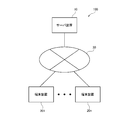
- FIG. 1 is a block diagram showing an example of a configuration of an ophthalmic image processing system corresponding to at least one of the embodiments of the present invention.
- the server device 10 and the terminal devices 201 to 20n (hereinafter, may be referred to as the terminal device 20 on behalf of these) are connected to a communication network. It is configured to be connectable to each other via 30.
- the server device 10 in FIG. 1 is made to function as an ophthalmic image processing device, and any of a plurality of terminal devices 201 to 20n is connected to the server device 10 functioning as an ophthalmic image processing device via a communication network. It may be used.
- the terminal device 20 may be configured to install a program for using the ophthalmic image processing device, or may be configured to use the program on the server via a browser.
- the ophthalmic image processing device described below it is not necessary that all the components of the ophthalmic image processing device described below are provided in the same device, and a part of the components of the ophthalmic image processing device is provided in another device, for example, a server device 10 that can be connected via a communication network.
- the plurality of terminal devices 201 to 20n may each be provided with a part of the configuration, and the ophthalmic image processing device may utilize the configuration provided in the other device while communicating. ..
- the number of server devices 10 is not limited to one, and a plurality of server devices may be used.
- the trained model which will be described later, is used not only when it is stored in a device as an ophthalmic image processing device, but also when it is distributed and provided in a server device 10 as another device, a plurality of terminal devices 201 to 20n, and the like. It may be configured to be used by connecting to a device provided with a trained model to be processed via a communication network each time. That is, as long as the trained model stored by some storage means can be used, it does not matter whether the trained model storage means is provided by the ophthalmologic image processing device itself or another device.
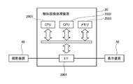
- FIG. 2 is a block diagram showing an example of the configuration of an ophthalmic image processing device and a peripheral device corresponding to at least one of the embodiments of the present invention.
- the terminal device 20 functions as an ophthalmic image processing device as an example, the description will be given with the same reference numerals as the terminal device, such as the ophthalmic image processing device 20. However, it is not limited to this.
- the ophthalmic image processing device 20 may be a device designed as a dedicated machine, but it is assumed that it can be realized by a general computer. That is, as shown in FIG. 2, the ophthalmic image processing device 20 includes a CPU (Central Processing Unit) 2001 and a GPU (Graphics Processing Unit: image processing unit) that a general computer would normally have. The apparatus) 2002 and the memory 2003 are at least provided. Further, the ophthalmic image processing device 20 is connected to the photographing device 40 and the display device 50, respectively, via the interface (I / F) 2003. Further, an input device such as a mouse or a keyboard, an output device such as a printer, and a communication device for connecting to a communication network may be connected via a bus.
- a bus such as a mouse or a keyboard, an output device such as a printer, and a communication device for connecting to a communication network may be connected via a bus.
- the processing in each part of the ophthalmic image processing apparatus 20 is realized by reading a program for executing the processing in each part from the memory and executing the processing in the CPU or GPU that functions as a control circuit (Processing circuit, Processing circuitry).
- the processor processing circuit
- the imaging device 40 is used to capture an ophthalmic image
- the display device 50 is used, for example, to display an ophthalmic image superimposed on an image showing a prediction result.
- FIG. 3 is an explanatory diagram showing an example of a configuration of a photographing device corresponding to at least one of the embodiments of the present invention.
- the photographing device 40 may be any as long as it can record an image of the eye to be imaged as digital data, and a conventionally known one may be appropriately used. For example, as shown in FIG. 3, imaging is performed.
- the device 40 is emitted from a light source 41 composed of a white LED or the like, and the light rays that have passed through the diaphragm pass through the lens 42, the splitter 43, and the objective lens 44 in this order, and are collected at the anterior segment 45 of the subject's eye. Be lit.
- the reflected light from the anterior segment 45 passes through the objective lens 44 and the splitter 43, passes through the imaging lens 46, and is imaged on the image sensor 47.
- the captured data imaged on the image sensor 47 is subjected to predetermined processing by the image processing engine and converted into image data and moving image data.
- the ophthalmic image captured by the imaging device 40 is transmitted to the ophthalmic image processing device 20.
- image is simply used, such as an ophthalmic image or a subdivision image, but it also includes the case where it refers to the content indicated by the "image” and the case where it refers to the data of the image. It shall be used as an expression.
- FIG. 4 is a block diagram showing an example of the configuration of an ophthalmic image processing apparatus corresponding to at least one of the embodiments of the present invention.
- the ophthalmic image processing device 20A includes an image acquisition unit 21, an extraction unit 22, a prediction unit 23, and a storage unit 24.
- the image acquisition unit 21 has a function of acquiring an ophthalmic image.
- the ophthalmologic image refers to an image obtained by photographing the target eye to be inspected.
- the ophthalmologic image is taken with an imaging range and imaging technique that can evaluate the condition of the eye to be evaluated.
- the state of the eye to be inspected refers to a specific state that can be used for evaluation of the eye to be inspected, and examples thereof include the occurrence of interference fringes in the tear film and the presence or absence of breaks in the tear film.
- the ophthalmic image is not limited to the image taken on the surface of the eye to be inspected, and the image obtained by the fundus camera, SLO (scanning fundus camera), OCT (optical interference tomography device), etc.
- the condition of the eye to be inspected is, for example, normal or abnormal blood vessel running abnormality, pigmentation associated with bleeding history, abnormal papillary shape, lipid accumulation, presence of fissure, etc. It is possible that there is a certain state.
- the state of the eye to be inspected in the case of OCT in addition to the above-mentioned examples in the case of the fundus camera and SLO, the presence of edema because a tomographic image can be taken, the abnormality of the layer structure of the tomography, and the photoreceptor part of the retina.
- the thickness (thinning when abnormal) is considered.
- the image acquisition unit 21 acquires an ophthalmic image captured by the imaging device 40.
- the extraction unit 22 has a function of extracting a plurality of subsection images from an ophthalmic image.
- the subdivision image refers to an image consisting of a region smaller in size than an ophthalmic image and having a size that is a unit for performing prediction processing described later.
- the size of the subsection image does not necessarily have to be a fixed size and can be set appropriately. However, if the size is extremely small, the condition of the target eye to be examined cannot be detected, and the size is extremely large. Then, an image containing many parts other than the target eye condition is detected as the corresponding image. Since problems occur at both extreme sizes, the target eye condition is appropriately detected. It is preferable to set it to a possible size.
- the prediction unit 23 has a function of predicting the state of the eye to be inspected for each subsection image based on a trained model that has been trained in advance.
- the learning process of the trained model extracts a plurality of subsection images from the ophthalmic image for training and predicts the state of the eye to be inspected for each subsection image by machine learning using the correct answer data regarding the state of each subsection image. It is done by.
- Various trained models can be applied as long as they are trained by machine learning. For example, training a neural network by deep learning is applicable. Furthermore, as an example, it is also possible to adopt a convolutional neural network (CNN).
- CNN convolutional neural network
- the size of the subsection image used for learning and the subsection image for testing extracted by the extraction unit 22 need to be the same size.
- the prediction unit 23 inputs the test subdivision image extracted by the extraction unit 22 into the trained model, predicts whether or not it has features corresponding to the state of the target eye to be inspected, and outputs the prediction result. Let me. The details of the learning process will be described later.
- the storage unit 24 has a function of storing information necessary for processing of each part in the ophthalmic image processing apparatus 20A, and also storing various information generated in the processing of each part. Further, the trained model 241 may be stored in the storage unit 24. The trained model may be stored in the server device 10 that can be connected via the communication network, and the server device 10 may have the function of the prediction unit 23.
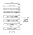
- FIG. 5 is a flowchart showing an example of a flow of learning processing corresponding to at least one of the embodiments of the present invention.
- the learning process is started by acquiring an ophthalmic image for learning in the ophthalmic image processing device 20A (step S101). It is preferable that a plurality of ophthalmic images are acquired.
- the ophthalmic image processing device 20A extracts a plurality of subsection images from the acquired ophthalmic image (step S102).
- the ophthalmic image processing device 20A acquires correct answer data for each subsection image (step S103).
- the subsection image acquired in this way and its correct answer data are stored as a set of teacher data sets. Learning is performed using a plurality of sets of such teacher data sets.
- the ophthalmic image processing device 20A uses a set of teacher data sets consisting of a subdivision image and its correct answer data to perform a process of predicting the state of the eye to be inspected based on the input subdivision image by a neural network. To obtain a prediction result (step S104). Further, the ophthalmic image processing apparatus 20A calculates the loss by calculation based on the loss function using the prediction result obtained by the prediction processing and the correct answer data, and the parameters (weight, bias) of the neural network so as to reduce the loss. Etc.) (step S105).
- the ophthalmologic image processing apparatus 20A determines whether or not the predetermined condition is satisfied (step S106).
- the predetermined conditions for example, the number of trials of the process of updating the parameters of the neural network reached the predetermined number, and the situation where the loss value of the loss function started to increase after recording the minimum was observed. Things can be considered.
- the ophthalmologic image processing apparatus 20A selects the next set of teacher data sets (step S107), returns to step S104, and returns to the next teacher data set. Is used to execute the processes of S104 and S105. In this way, the ophthalmologic image processing apparatus 20A repeats the processes of S104 and S105 while changing the teacher data set until the predetermined condition is satisfied, and ends the learning process when the predetermined condition is satisfied (S106-Yes).
- a plurality of sets of teacher data sets may be divided into a plurality of groups having a predetermined batch size, and mini-batch learning may be performed with the processing of each group as one learning delimiter.
- all teacher data sets are used only once by performing learning processing for all groups in mini-batch learning, but by setting the number of epochs to a predetermined size, one set of teacher data sets can be used multiple times. (The number set as the number of epochs) may be set to be used for learning.
- transfer learning may be performed by diverting the trained model used for image recognition other than ophthalmic images.
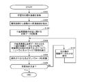
- FIG. 6 is a flowchart showing an example of a flow of prediction processing corresponding to at least one of the embodiments of the present invention.
- the prediction process is started by acquiring a test ophthalmic image in the ophthalmic image processing apparatus 20A (step S201).
- the ophthalmic image processing device 20A extracts a plurality of subsection images from the acquired ophthalmic image (step S202).
- the ophthalmic image processing apparatus 20A inputs a subsection image into the trained model that has been trained in advance for predicting the state of the eye to be inspected, executes the prediction process, and obtains the prediction result (step S203). ).
- the ophthalmologic image processing device 20A determines whether or not the prediction processing has been completed for all the subsection images (step S204).
- the ophthalmologic image processing apparatus 20A selects the next subdivision image (step S205) and returns to step S203. In this way, the prediction processing is sequentially executed for the subdivision images, and when the prediction processing for all the subdivision images is completed (S204-Yes), the ophthalmic image processing apparatus 20A performs the prediction processing on the ophthalmic images. An image showing the prediction result is superimposed and displayed (step S206), and the prediction process is completed.
- FIG. 7 is an explanatory diagram showing an example of an ophthalmic image in which the ophthalmic image before the prediction processing and the prediction processing result are superimposed and displayed.
- FIG. 7A shows a case where tear breakup is learned as the state of the eye to be predicted, the left side is the acquired ophthalmic image, and the right side is the superimposed display of the image showing the prediction result. ..
- the square-shaped part is the part predicted as the part where the tear breakup occurred. Each square is the size of the parcel image. It can be seen that the tear breakdown to be detected is accurately detected. Further, FIG.
- FIG. 7B shows a case where tear interference fringes are learned as the state of the eye to be predicted, and the left side is the acquired ophthalmic image and the right side is the superimposed display of the image showing the prediction result. Is.
- the square-shaped part is the part predicted as the part where the tear interference fringes occur. Each square is the size of the parcel image. It can be seen that the tear interference fringes to be detected are accurately detected.
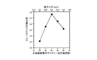
- the size of the subsection image can be set to various sizes, but it is preferable that the size is such that the state of the target eye to be inspected can be detected with high accuracy. Therefore, we verified the optimum size of the subdivision image.
- the optimum subsection image size for breakup detection was verified.
- the size of the subdivision image used for learning the detection of breakup is prepared from the size of 20 pixels in height ⁇ 20 pixels in width to the size of 60 pixels in height ⁇ 60 pixels in width at 10 pixel intervals, and CNN (simple 3 layers). Learning and inference were performed in (using a model).
- FIG. 8 is a chart showing the relationship between the size of the subdivision image and the detection rate of the breakup.
- the graph of the calculated accuracy rate for each subsection image size shows that there is a clearly valid size range.
- the highest detection rate was in the case of 40 pixels ⁇ 40 pixels, and the actual size in that case was a size of 0.60 mm on a side.
- the correct answer rate should be set appropriately, but for example, if the correct answer rate of 60% or more is a preferable condition, the range of 30 ⁇ 30 pixels to 55 ⁇ 55 pixels. That is, it is desirable to set the image so that one side of the actual size is a small section image having a size of about 0.45 mm to 0.85 mm.
- a VGA type image having a size of horizontal ⁇ vertical 640 ⁇ 480 pixels was used as the size of the ophthalmic image.
- the size of the subdivision image used for learning the detection of the striped pattern is prepared at 16 pixel intervals from the size of 16 pixels vertically ⁇ 16 pixels horizontally to the size of 80 pixels vertically ⁇ 80 pixels horizontally, and learning and inference are performed by CNN. It was.
- the teardrop interference fringes of healthy subjects are grayish stripes, but the colors (hue) of the interference fringes of healthy subjects and patients with hyperevaporative dry eye are very similar, and the stripes.
- FIG. 9 is a chart showing the relationship between the size of the subsection image and the detection rate of tear interference fringes.
- the relationship between the size of the subsection image and the accuracy rate of the prediction is calculated in advance and set to a size that is equal to or greater than a predetermined accuracy rate.
- a determination method such as setting the size of the subsection image can be considered.
- an image acquisition unit that acquires an ophthalmic image to be evaluated, an extraction unit that extracts a plurality of subdivision images from the ophthalmic image, and a plurality of ophthalmic images for learning.
- a trained model that has been trained in advance about predicting the state of the eye to be examined for each subsection image by machine learning using the correct answer data regarding the state of each subsection image.
- Each section image has a prediction unit that predicts the state of the eye to be inspected, and the subsection image is extracted from the ophthalmic image so that the image size corresponds to the state of the eye to be evaluated.
- the state of the eye examination can be predicted with high accuracy, and the prediction result for each subsection image can be obtained, so that the state of the eye to be examined can be analyzed in detail.
- the ophthalmic image processing system of the present invention can be realized as a single ophthalmic image processing device that does not need to be connected to another device via a communication network. Therefore, in the following description, it will be described as an ophthalmic image processing device.
- the same reference numerals may be used for the same configurations as those in the first embodiment, and the description thereof may be omitted.
- FIG. 10 is a block diagram showing an example of the configuration of an ophthalmic image processing apparatus corresponding to at least one of the embodiments of the present invention.
- the ophthalmic image processing device 20B includes an image acquisition unit 21, a result reflection area setting unit 25, an extraction unit 22B, a prediction unit 23B, and a storage unit 24.
- the result reflection area setting unit 25 has a function of setting a result reflection area for reflecting the prediction result of the small area image, which is an area having a predetermined size equal to or smaller than the size of the small area image.
- the result reflection area is an area for finally reflecting the prediction result regarding the state of the eye to be inspected with respect to the ophthalmologic image.
- the range of the subsection image used for the prediction process and the range reflecting the prediction result are the same area, but in this second embodiment, the size of the subsection image used for the prediction process is smaller than Set the result reflection area consisting of the size of. That is, an image having a relatively large size is used for the prediction process, but a result reflecting area having a relatively small size is used as the area for reflecting the result.
- the result reflection area may be set based on any regularity, but for example, it is preferable to fill the ophthalmic image with a plurality of result reflection areas without gaps.
- the result reflection area is an area set one-to-one with the subsection image.
- the set result reflection area is stored in the storage unit 24.
- the extraction unit 22B has a function of including the result reflection area and extracting an area having a predetermined size larger than the result reflection area as a small section image corresponding to each of the result reflection areas.
- the positional relationship between the subdivision image and the result reflection area may be any as long as the result reflection area is included.
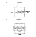
- the result reflection area is set to the size of 20 pixels in the vertical direction and 20 pixels in the horizontal direction, and the small section image is extracted in the size of 48 pixels in the vertical direction and 48 pixels in the horizontal direction so that the result reflection area is located in the center. Can be considered.
- the two subdivision images corresponding to each of the two adjacent result reflection areas have overlapping pixel areas. May be included.
- the extracted subsection image is stored in the storage unit 24.
- the prediction unit 23B has a function of predicting the state of the eye to be inspected for each subsection image based on a trained model that has been trained in advance, and further, a result corresponding to the prediction result obtained for each subsection image. It has a function to reflect on the reflection area.
- the prediction processing is sequentially executed for the plurality of subsection images.
- the obtained prediction result is reflected in the corresponding result reflection area.
- the reflection result for the obtained result reflection area is stored in the storage unit 24.
- the display device 50 may be configured to superimpose and display an image showing the prediction result for each result reflection region on the ophthalmic image and output it to the display device 50.
- the learning process for obtaining the trained model used in the prediction unit 23B is the same as that of the first embodiment, and thus the description thereof will be omitted.
- FIG. 11 is a flowchart showing an example of a flow of prediction processing corresponding to at least one of the embodiments of the present invention.
- the prediction process is started by acquiring a test ophthalmic image in the ophthalmic image processing apparatus 20B (step S301).
- the ophthalmic image processing device 20B sets a plurality of result reflection areas for the acquired ophthalmic image (step S302).
- the ophthalmic image processing device 20B extracts a small section image corresponding to each result reflection region (step S303).
- the ophthalmic image processing device 20B inputs a subsection image to the trained model that has been trained in advance to predict the state of the eye to be inspected, executes the prediction process, and obtains the prediction result (step S304). ). Further, the ophthalmologic image processing apparatus 20B reflects the prediction result obtained for the subdivision image on the corresponding result reflection area (step S305). Then, the ophthalmologic image processing apparatus 20B determines whether or not the prediction processing has been completed for all the subdivision images (step S306). When the prediction processing is not completed for all the subdivision images (S306-No), the ophthalmologic image processing apparatus 20B selects the next subdivision image (step S307) and returns to step S304.
- the prediction processing is sequentially executed for the subdivision images, and when the prediction processing for all the subdivision images is completed (S306-Yes), the ophthalmic image processing apparatus 20B performs the prediction processing on the ophthalmic images. An image showing the prediction result is superimposed and displayed (step S308), and the prediction process is completed.
- FIG. 12 is an explanatory diagram for explaining an example of setting a result reflection area and a small section image.
- the result reflection areas A, B, and C having a size of 20 pixels in the vertical direction and 20 pixels in the horizontal direction are set adjacent to each other.
- the subdivision images A, B, and C corresponding to the result reflection areas A, B, and C are extracted in a size of 48 pixels vertically ⁇ 48 pixels horizontally so that the result reflection area is located at the center.
- FIG. 12A it can be seen that the subsection image A is extracted so that the result reflection region A is located at the center.
- the subsection image B corresponding to the adjacent result reflection region B is extracted in a form including the pixel region overlapping with the subsection image A.
- the result reflection in which the result reflection area for reflecting the prediction result of the small section image is set in the area having a predetermined size equal to or smaller than the size of the small section image. It further has an area setting unit, and the extraction unit corresponds to each of the result reflection areas so as to include the result reflection area and extract an area having a predetermined size larger than the result reflection area as a small section image for prediction.
- the prediction results obtained for each subsection image are reflected in the corresponding result reflection area, so the processing for predicting the state of the eye to be examined is large so that the prediction accuracy rate is improved.
- the ophthalmic image processing system of the present invention can be realized as a single ophthalmic image processing device that does not need to be connected to another device via a communication network. Therefore, in the following description, it will be described as an ophthalmic image processing device.
- the same reference numerals may be used for the same configurations as those of the first and second embodiments, and the description thereof may be omitted.
- FIG. 13 is a block diagram showing an example of the configuration of an ophthalmic image processing apparatus corresponding to at least one of the embodiments of the present invention.
- the ophthalmic image processing device 20C includes an image acquisition unit 21, a result reflection area setting unit 25, an extraction unit 22C, an edge image generation unit 26, a prediction unit 23C, and a storage unit 24. It has.
- the extraction unit 22C has a function of including the result reflection area and extracting an area having a predetermined size larger than the result reflection area as a small section image corresponding to each of the result reflection areas.
- the edge image generation unit 26 has a function of extracting an edge from an ophthalmic image and generating an edge image.
- the edge image refers to an image in which a portion of the image in which the change in the luminance value is large is extracted as an edge. Since the edge image is an image showing where the edge exists in the ophthalmic image, it is basically the same size as the ophthalmic image.
- the edge image is, for example, an image generated so that the portion extracted as an edge has a high luminance value (the stronger the edge, the higher the luminance value), and the non-edge portion has a lower luminance value.
- the edge image is used to improve the efficiency of the prediction process on the premise that the portion extracted as the edge is a location that is likely to be the target to be extracted as the state of the eye to be inspected. Any method may be used as long as it is possible to generate an edge image, and for example, a known Sobel filter may be used in the edge image generation.
- the generated edge image is stored in the storage unit 24.
- the prediction unit 23C has a function of predicting the state of the eye to be inspected for each subsection image based on a trained model that has been trained in advance, and the brightness value in the edge image corresponding to the position of the result reflection region is When it is equal to or more than a predetermined threshold value, it has a function of setting a subdivision image corresponding to the result reflection area as a target of prediction processing, and further, a result reflection area corresponding to the prediction result obtained for each subdivision image. Has a function to reflect on. That is, when the prediction processing is executed for all the result reflection areas set in the result reflection area setting unit 25, it takes a long time to complete the prediction processing for one ophthalmic image. In addition, the higher the resolution of the ophthalmic image, the longer the processing time.
- the part where the edge image is not included in the result judgment area is likely not to include the target to be extracted as the state of the eye to be inspected, and is excluded from the target of the prediction processing. To do. That is, only the part including the edge image in the result determination area is set as the target of the prediction processing. By performing such processing, it is possible to shorten the processing time required for the prediction processing.
- FIG. 14 is a flowchart showing an example of a flow of prediction processing corresponding to at least one of the embodiments of the present invention.
- the prediction process is started by acquiring a test ophthalmic image in the ophthalmic image processing apparatus 20C (step S401).
- the ophthalmic image processing device 20C sets a plurality of result reflection areas for the acquired ophthalmic image (step S402).
- the ophthalmic image processing device 20C extracts a subdivision image corresponding to each result reflection region (step S403).
- the ophthalmic image processing device 20C generates an edge image from the ophthalmic image (step S404).
- the ophthalmic image processing device 20C sets the subsection image corresponding to the result reflection region as the target of the prediction processing for the edge image having the brightness value equal to or more than a predetermined threshold value corresponding to the position of the result reflection region (Ste S405).
- the ophthalmic image processing device 20C inputs a subsection image to be predicted to a trained model that has been trained in advance to predict the state of the eye to be inspected, executes the prediction process, and outputs the prediction result.
- Obtain step S406.
- the ophthalmologic image processing apparatus 20C reflects the prediction result obtained for the subdivision image on the corresponding result reflection area (step S407).
- the ophthalmic image processing device 20C determines whether or not the prediction processing is completed for all the small area images to be predicted processing (step S408).
- the ophthalmic image processing apparatus 20C selects the next subsection image to be predicted to be predicted (step S409).
- the prediction processing is sequentially executed for the subdivision images to be predicted processing, and when the prediction processing is completed for all the subdivision images to be predicted processing (S408-Yes), the ophthalmic image processing apparatus.
- an image showing the prediction result is superimposed and displayed on the ophthalmic image (step S410), and the prediction process is completed.
- an edge image generation unit that extracts an edge from the ophthalmic image and generates an edge image
- the prediction unit has an edge corresponding to the position of the result reflection region.
- the subsection image corresponding to the result reflection area is set as the target of the prediction processing, so that the target to be extracted may be included as the state of the eye to be inspected. Only the result reflection area including the edge having a high luminance value or more is extracted, and only the small section image corresponding to the extracted result reflection area can be the target of the prediction processing. Therefore, the processing time required for the prediction processing can be reduced. It can be shortened.
- the prediction unit 23 calculates the average brightness value for each subdivision image, and sets the subdivision image whose average brightness value is equal to or greater than a predetermined threshold value as the target of the prediction processing. You may try to do it.
- the parts of the ophthalmic image that are not necessary for predicting the condition of the eye to be inspected are black (dark) and have a very low brightness value. Since it is clear that such a part does not include the target to be extracted as the state of the eye to be inspected, if such a part can be excluded from the target of the prediction processing, the processing time required for the prediction processing Can be shortened. Therefore, the prediction unit 23 calculates the average luminance value for each subsection image, sets the subsection image whose average luminance value is equal to or greater than a predetermined threshold value to be the target of the prediction processing, and the average luminance value is smaller than the predetermined threshold value. By excluding the section image from the target of the prediction processing, the processing time required for the prediction processing can be shortened.
- the part outside the field of view, the part of the eyelashes, etc. are removed, and further, learning is performed.
- the edge image generation unit In addition to the configuration of the first to third embodiments, whether or not the edge image generation unit generates an edge image from the ophthalmic image and sets the subdivision image as the target of the prediction processing using the edge image. You may decide.
- the present invention by subdividing the ophthalmic image that is the target of the prediction processing, it is possible to identify and display the position of the structure of interest in the image, but this makes it possible to display many subsection images.
- the analysis time is long because the inference must be performed.
- many of the generated subsection images do not require inference, and if these can be excluded from the inference target in advance, it can be expected that the inference time will be significantly reduced.
- the structure of interest in an image has a clear outline or a dense structure of complex structures, so if such a part can be extracted by some method, any subdivision image should be inferred. You can judge whether it is or not.
- an edge image is generated from the ophthalmic image by adopting the same configuration as the edge image generation unit 26 described in the third embodiment.
- the prediction unit 23 determines whether or not the edge image corresponding to the position of each subsection image includes the edge portion. Specifically, it is determined whether or not to set the object of measurement processing according to the intensity of the brightness of the edge image corresponding to the position of the subdivision image.
- Various conditions can be set for the intensity of the brightness of the edge image, such as the average value, the maximum value, the median value, and the standard deviation of the brightness values.
- the subsection image that does not include the edge is set out of the target of the prediction processing to remove the part outside the field of view, the part of the eyelashes, and the like, and further, the trained model is used.
- the eyelashes and contours By training the eyelashes and contours to be predicted as not to be extracted at the learning stage, the eyelashes and contours existing in the subdivision image including the edges can be detected even during the prediction process by the prediction unit 23. It is possible to determine that the main subdivision image is not subject to the prediction processing (predict to classify it as "not applicable” or "other”). In this way, by removing and excluding unnecessary parts such as parts outside the field of view and parts of the eyelashes by the two means, it is expected that the prediction speed will be further increased and the prediction accuracy will be further improved.
- the image acquisition unit 21 acquires a plurality of ophthalmic images arranged in a time series
- the prediction unit 23 executes a prediction process for each of the plurality of ophthalmic images, and further obtains each of the plurality of ophthalmic images.
- a change determination unit for determining whether or not the temporal change and / or the spatial change of the state of the eye to be inspected satisfies a predetermined condition may be further provided.
- the ophthalmic image processing system of the present invention can be realized as a single ophthalmic image processing device that does not need to be connected to another device via a communication network. It does not have to be a processing system. The following description will be given on the premise that it may function as an ophthalmic image processing system.
- FIG. 15 is a block diagram showing an example of the configuration of an ophthalmic image processing system corresponding to at least one of the embodiments of the present invention.
- the server device 10 and the terminal devices 201 to 20n (hereinafter, may be referred to as the terminal device 20 on behalf of these) are connected to a communication network. It is configured so that it can be connected to each other via 30.
- the server device 10 in FIG. 15 is made to function as an ophthalmic image processing device, and any of a plurality of terminal devices 201 to 20n is connected to the server device 10 functioning as an ophthalmic image processing device via a communication network. It may be used.
- the terminal device 20 may be configured to install a program for using the ophthalmic image processing device, or may be configured to use the program on the server via a browser.
- the ophthalmic image processing device described below it is not necessary that all the components of the ophthalmic image processing device described below are provided in the same device, and a part of the components of the ophthalmic image processing device is provided in another device, for example, a server device 10 that can be connected via a communication network.
- the plurality of terminal devices 201 to 20n may each be provided with a part of the configuration, and the ophthalmic image processing device may utilize the configuration provided in the other device while communicating. ..
- the number of server devices 10 is not limited to one, and a plurality of server devices may be used.
- the trained model which will be described later, is used not only when it is stored in a device as an ophthalmic image processing device, but also when it is distributed and provided in a server device 10 as another device, a plurality of terminal devices 201 to 20n, and the like. It may be configured to be used by connecting to a device provided with a trained model to be processed via a communication network each time. That is, as long as the trained model stored by some storage means can be used, it does not matter whether the trained model storage means is provided by the ophthalmologic image processing device itself or another device.
- FIG. 16 is a block diagram showing an example of the configuration of an ophthalmic image processing device and a peripheral device corresponding to at least one of the embodiments of the present invention.
- the terminal device 20 functions as an ophthalmic image processing device as an example, the description will be given with the same reference numerals as the terminal device, such as the ophthalmic image processing device 20. However, it is not limited to this.
- the ophthalmic image processing device 20 may be a device designed as a dedicated machine, but it is assumed that it can be realized by a general computer. That is, as shown in FIG. 16, the ophthalmic image processing device 20 includes at least a CPU (Central Processing Unit) 2001 and a memory 2003 that a general computer would normally have. Further, it is preferable to have a GPU (Graphics Processing Unit) 2002. Further, the ophthalmic image processing device 20 is connected to the photographing device 40 and the display device 50, respectively, via the interface (I / F) 2003. Further, an input device such as a mouse or a keyboard, an output device such as a printer, and a communication device for connecting to a communication network may be connected via a bus.
- a bus for connecting to a communication network
- the processing in each part of the ophthalmic image processing apparatus 20 is realized by reading a program for executing the processing in each part from the memory and executing the processing in the CPU or GPU that functions as a control circuit (Processing circuit, Processing circuitry).
- the processor processing circuit
- the imaging device 40 is used to capture an ophthalmic image
- the display device 50 is used, for example, to display an ophthalmic image superimposed on an image showing a prediction result.
- the ophthalmic image processing device 20 can be used in any device as long as it can perform processing equivalent to that of a computer, and can be realized by, for example, a smartphone or a tablet terminal. It is possible.
- FIG. 17 is an explanatory diagram showing an example of a configuration of a photographing device corresponding to at least one of the embodiments of the present invention.
- the photographing device 40 may be any as long as it can record an image of the eye to be imaged as digital data, and a conventionally known one may be appropriately used. For example, as shown in the outline in FIG. 17, imaging is performed.
- the device 40 is emitted from a light source 41 composed of a white LED or the like, and the light rays that have passed through the diaphragm pass through the lens 42, the splitter 43, and the objective lens 44 in this order, and are collected at the anterior segment 45 of the subject's eye. Be lit.
- the reflected light from the anterior segment 45 passes through the objective lens 44 and the splitter 43, passes through the imaging lens 46, and is imaged on the image sensor 47.
- the captured data imaged on the image sensor 47 is subjected to predetermined processing by the image processing engine and converted into image data and moving image data.
- the ophthalmic image captured by the imaging device 40 is transmitted to the ophthalmic image processing device 20.
- image is simply used, such as an ophthalmic image or a subdivision image, but it also includes the case where it refers to the content indicated by the "image” and the case where it refers to the data of the image. It shall be used as an expression.
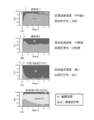
- FIG. 18 is an explanatory diagram showing a state of dry eye of an eye to be evaluated as an evaluation target in an ophthalmic image processing apparatus corresponding to at least one of the embodiments of the present invention.
- the dry eye states of the eye to be inspected are (a) a healthy subject (not a dry eye) and (b) an enhanced evaporation type dry eye.
- the state of (c) and the state of (c) tear-reducing dry eye are configured so as to be able to predict at least three states.
- the state of a healthy person is a healthy state in which the oil layer and the liquid layer of tears are maintained in a well-balanced manner, and is characterized in that slightly dark gray interference fringes with low saturation are observed. ..
- the state of enhanced evaporation type dry eye is a state in which the evaporation of tear fluid is accelerated, and is characterized in that a dark and smooth state is observed.
- the state of tear-reducing dry eye is a state in which the amount of tears secreted is reduced, and is characterized in that highly saturated interference fringes are observed.
- FIG. 19 is a block diagram showing an example of the configuration of an ophthalmic image processing apparatus corresponding to at least one of the embodiments of the present invention.
- the ophthalmic image processing device 20A includes an image acquisition unit 21, an extraction unit 22, a prediction unit 23, and a storage unit 24.
- the image acquisition unit 21 has a function of acquiring an ophthalmic image.
- the ophthalmologic image refers to an image obtained by photographing the target eye to be inspected.
- the ophthalmologic image is taken with an imaging range and imaging technique that can evaluate the dry eye condition of the eye to be evaluated.
- the state of dry eye of the eye to be inspected refers to a specific state that can be used for evaluation of the dry eye of the eye to be inspected.
- the image acquisition unit 21 acquires an ophthalmic image captured by the imaging device 40.
- the extraction unit 22 has a function of extracting a plurality of subsection images from an ophthalmic image.
- the subdivision image refers to an image consisting of a region smaller in size than an ophthalmic image and having a size that is a unit for performing prediction processing described later.
- the size of the subsection image does not necessarily have to be a fixed size and can be set appropriately. However, if the size is extremely small, the state of dry eye of the target eye cannot be detected, and the size is extremely small. In the case of a large size, a problem occurs in both extreme sizes, such as detecting an image containing many parts other than the dry eye condition part of the target eye as the corresponding image. It is preferable to set the dry eye condition to a size that can be appropriately detected.
- the prediction unit 23 has a function of predicting the state of dry eye of the eye to be inspected for each subsection image based on a trained model that has been trained in advance.
- a trained model In the learning process of the trained model, a plurality of subsection images are extracted from the ophthalmic image for learning, and the state of the dry eye of the eye to be inspected for each subsection image by machine learning using the correct answer data regarding the state of each subsection image. It is done by predicting.
- Various trained models can be applied as long as they are trained by machine learning. For example, training a neural network by deep learning is applicable. Furthermore, as an example, it is also possible to adopt a convolutional neural network (CNN).
- CNN convolutional neural network
- the size of the subsection image used for learning and the subsection image for testing extracted by the extraction unit 22 need to be the same size.
- the prediction unit 23 inputs the test subdivision image extracted by the extraction unit 22 into the trained model to predict whether or not it has features corresponding to the dry eye condition of the target eye to be inspected, and predicts. Output the result. The details of the learning process will be described later.
- the storage unit 24 has a function of storing information necessary for processing of each part in the ophthalmic image processing apparatus 20A, and also storing various information generated in the processing of each part. Further, the trained model 241 may be stored in the storage unit 24. The trained model may be stored in the server device 10 that can be connected via the communication network, and the server device 10 may have the function of the prediction unit 23.
- FIG. 20 is a flowchart showing an example of a flow of learning processing corresponding to at least one of the embodiments of the present invention.
- the learning process is started by acquiring an ophthalmic image for learning in the ophthalmic image processing device 20A (step S101). It is preferable that a plurality of ophthalmic images are acquired.
- the ophthalmic image processing device 20A extracts a plurality of subsection images from the acquired ophthalmic image (step S102).
- the ophthalmic image processing device 20A acquires correct answer data for each subsection image (step S103).
- the subsection image acquired in this way and its correct answer data are stored as a set of teacher data sets. Learning is performed using a plurality of sets of such teacher data sets.
- the ophthalmic image processing device 20A uses a set of teacher data sets consisting of a subdivision image and its correct answer data, and predicts the state of dry eye of the eye to be inspected based on the input subdivision image. Is executed by the neural network to obtain the prediction result (step S104). Further, the ophthalmic image processing apparatus 20A calculates the loss by calculation based on the loss function using the prediction result obtained by the prediction processing and the correct answer data, and the parameters (weight, bias) of the neural network so as to reduce the loss. Etc.) (step S105).
- the ophthalmologic image processing apparatus 20A determines whether or not the predetermined condition is satisfied (step S106).
- the predetermined conditions for example, the number of trials of the process of updating the parameters of the neural network reached the predetermined number, and the situation where the loss value of the loss function started to increase after recording the minimum was observed. Things can be considered.
- the ophthalmologic image processing apparatus 20A selects the next set of teacher data sets (step S107), returns to step S104, and returns to the next teacher data set. Is used to execute the processes of S104 and S105. In this way, the ophthalmologic image processing apparatus 20A repeats the processes of S104 and S105 while changing the teacher data set until the predetermined condition is satisfied, and ends the learning process when the predetermined condition is satisfied (S106-Yes).
- a plurality of sets of teacher data sets may be divided into a plurality of groups having a predetermined batch size, and mini-batch learning may be performed with the processing of each group as one learning delimiter.
- all teacher data sets are used only once by performing learning processing for all groups in mini-batch learning, but by setting the number of epochs to a predetermined size, one set of teacher data sets can be used multiple times. (The number set as the number of epochs) may be set to be used for learning.
- transfer learning may be performed by diverting the trained model used for image recognition other than ophthalmic images.
- FIG. 21 is a flowchart showing an example of a flow of prediction processing corresponding to at least one of the embodiments of the present invention.
- the prediction process is started by acquiring a test ophthalmic image in the ophthalmic image processing apparatus 20A (step S201).
- the ophthalmic image processing device 20A extracts a plurality of subsection images from the acquired ophthalmic image (step S202).
- the ophthalmic image processing device 20A inputs a subsection image into a trained model that has been trained in advance about predicting the state of dry eye of the eye to be inspected, executes prediction processing, and obtains a prediction result.
- Step S203 the ophthalmologic image processing device 20A determines whether or not the prediction processing has been completed for all the subsection images (step S204).
- the ophthalmologic image processing apparatus 20A selects the next subdivision image (step S205) and returns to step S203. In this way, the prediction processing is sequentially executed for the subdivision images, and when the prediction processing for all the subdivision images is completed (S204-Yes), the ophthalmic image processing apparatus 20A performs the prediction processing on the ophthalmic images. An image showing the prediction result is superimposed and displayed (step S206), and the prediction process is completed.
- FIG. 22 is an explanatory diagram for explaining the relationship between the size of the subdivision image and whether or not the striped pattern can be detected.
- the size of the subsection image can be set to various sizes, but it is preferable that the size is such that the state of the dry eye of the target eye to be inspected can be detected with high accuracy. Therefore, the optimum size of the subdivision image was verified by confirming the detection accuracy while changing the size of the subdivision image in various ways.
- FIG. 22A shows a case where the size of the subdivision image is set to 8 pixels in the vertical direction and 8 pixels in the horizontal direction, and the prediction accuracy is low in the case of the size of 8 pixels ⁇ 8 pixels. That is, the striped pattern of the tear interference fringes cannot be detected. This state is because, as shown in FIG.
- FIG. 22A shows a case where the size of the subdivision image is set to 24 pixels in the vertical direction ⁇ 24 pixels in the horizontal direction, and in the case of the size of 24 pixels ⁇ 24 pixels, 8 in FIG. 22 (a). Although the prediction accuracy is higher than that of the pixel ⁇ 8 pixel size, the prediction accuracy is not sufficient. As shown in FIG. 22B, this state may not be predicted as a striped pattern because the size of the border of the striped pattern may be such that the subdivision image cannot be detected. Therefore, it is presumed that the prediction accuracy does not increase sufficiently.
- FIG. 22B shows a case where the size of the subdivision image is set to 24 pixels in the vertical direction ⁇ 24 pixels in the horizontal direction, and in the case of the size of 24 pixels ⁇ 24 pixels, 8 in FIG. 22 (a). Although the prediction accuracy is higher than that of the pixel ⁇ 8 pixel size, the prediction accuracy is not sufficient. As shown in FIG. 22B, this state may not be predicted as a striped pattern because the size of the border of the striped pattern
- this state fails to detect the state of dry eye including the striped pattern because the size of the subsection image is set to be sufficiently large for the size of the striped pattern. Is presumed to be unlikely to occur. For this reason as well, in the present invention in which it is necessary to detect a striped pattern as the state of dry eye of the eye to be inspected, it is not preferable to set the size of the small section image too small, and in consideration of the prediction accuracy, it is not preferable. It is preferable to set the size of the subsection image to obtain the desired prediction accuracy.
- the relationship between the size of the subsection image and the accuracy rate of the prediction Is calculated in advance, and a determination method such as setting the size to be equal to or greater than a predetermined accuracy rate can be considered.
- a determination method such as setting the size to be equal to or greater than a predetermined accuracy rate can be considered.
- a determination method such as setting the size of the subdivision image can be considered.
- FIG. 23 is an explanatory diagram showing an example of an ophthalmic image in which the ophthalmic image before the prediction processing and the prediction processing result are superimposed and displayed.
- FIG. 23 (a) shows an ophthalmic image containing a large amount of tear-reducing dry eye as an ophthalmic image to be predicted
- FIG. 23 (b) shows a prediction result with respect to the ophthalmic image. The image is superimposed and displayed.
- FIGS. 23 (a) and 23 (b) there are many Jupiter locations showing the predicted state of tear-reducing dry eye, and it can be seen that the prediction can be performed accurately.
- an image acquisition unit that acquires the ophthalmic image to be evaluated, an extraction unit that extracts a plurality of subsection images from the ophthalmic image, and an ophthalmic image for learning.
- Multiple subsection images are extracted from the ophthalmology, and using the correct answer data regarding the state of each subsection image, at least a healthy state of dry eye of the subject to be examined for each subsection image by machine learning, tear-reducing dry eye.
- Prediction unit that predicts the dry eye state of the eye to be inspected for each subsection image based on a trained model that has been trained in advance to predict whether it corresponds to the state of dry eye or the state of hyperevaporative dry eye.
- the subsection image is extracted from the ophthalmic image so that the dry eye condition of the eye to be evaluated has an image size that can be appropriately evaluated, the dry eye condition of the eye to be evaluated can be determined. It is possible to make predictions with high accuracy, and since the prediction results for each subsection image can be obtained, it is possible to analyze the state of dry eye of the eye to be inspected in detail.
- the ophthalmic image processing system of the present invention can be realized as a single ophthalmic image processing device that does not need to be connected to another device via a communication network. Therefore, in the following description, it will be described as an ophthalmic image processing device.
- the same reference numerals may be used for the same configurations as those of the seventh embodiment, and the description thereof may be omitted.
- FIG. 24 is a block diagram showing an example of the configuration of an ophthalmic image processing apparatus corresponding to at least one of the embodiments of the present invention.
- the ophthalmic image processing device 20B includes an image acquisition unit 21, a result reflection area setting unit 25, an extraction unit 22B, a prediction unit 23B, and a storage unit 24.
- the result reflection area setting unit 25 has a function of setting a result reflection area for reflecting the prediction result of the small area image, which is an area having a predetermined size equal to or smaller than the size of the small area image.
- the result reflection area is an area for finally reflecting the prediction result regarding the state of dry eye of the eye to be inspected with respect to the ophthalmologic image.
- the range of the subsection image used for the prediction process and the range in which the prediction result is reflected are the same area, but in the eighth embodiment, the size of the subsection image used in the prediction process or less. Set the result reflection area consisting of the size of.
- the result reflection area may be set based on any regularity, but for example, it is preferable to fill the ophthalmic image with a plurality of result reflection areas without gaps.
- the result reflection area is an area set one-to-one with the subsection image.
- the set result reflection area is stored in the storage unit 24.
- the extraction unit 22B has a function of including the result reflection area and extracting an area having a predetermined size larger than the result reflection area as a small section image corresponding to each of the result reflection areas.
- the positional relationship between the subdivision image and the result reflection area may be any as long as the result reflection area is included.
- the result reflection area is set to the size of 20 pixels in the vertical direction and 20 pixels in the horizontal direction, and the small section image is extracted in the size of 48 pixels in the vertical direction and 48 pixels in the horizontal direction so that the result reflection area is located in the center. Can be considered.
- the two subdivision images corresponding to each of the two adjacent result reflection areas have overlapping pixel areas. May be included.
- the extracted subsection image is stored in the storage unit 24.
- the prediction unit 23B has a function of predicting the state of dry eye of the eye to be inspected for each subsection image based on a trained model that has been trained in advance, and further, the prediction result obtained for each subsection image is obtained. It has a function to reflect to the corresponding result reflection area.
- the prediction processing is sequentially executed for the plurality of subsection images.
- the obtained prediction result is reflected in the corresponding result reflection area.
- the reflection result for the obtained result reflection area is stored in the storage unit 24.
- the display device 50 may be configured to superimpose and display an image showing the prediction result for each result reflection region on the ophthalmic image and output it to the display device 50.
- the learning process for obtaining the trained model used in the prediction unit 23B is the same as that of the seventh embodiment, and thus the description thereof will be omitted.
- FIG. 25 is a flowchart showing an example of a flow of prediction processing corresponding to at least one of the embodiments of the present invention.
- the prediction process is started by acquiring a test ophthalmic image in the ophthalmic image processing apparatus 20B (step S301).
- the ophthalmic image processing device 20B sets a plurality of result reflection areas for the acquired ophthalmic image (step S302).
- the ophthalmic image processing device 20B extracts a small section image corresponding to each result reflection region (step S303).
- the ophthalmic image processing device 20B inputs a subsection image into a trained model that has been trained in advance about predicting the state of dry eye of the eye to be inspected, executes prediction processing, and obtains a prediction result. (Step S304). Further, the ophthalmologic image processing apparatus 20B reflects the prediction result obtained for the subdivision image on the corresponding result reflection area (step S305). Then, the ophthalmologic image processing apparatus 20B determines whether or not the prediction processing has been completed for all the subdivision images (step S306). When the prediction processing is not completed for all the subdivision images (S306-No), the ophthalmologic image processing apparatus 20B selects the next subdivision image (step S307) and returns to step S304.
- the prediction processing is sequentially executed for the subdivision images, and when the prediction processing for all the subdivision images is completed (S306-Yes), the ophthalmic image processing apparatus 20B performs the prediction processing on the ophthalmic images. An image showing the prediction result is superimposed and displayed (step S308), and the prediction process is completed.
- FIG. 26 is an explanatory diagram for explaining an example of setting a result reflection area and a small section image.
- the result reflection areas A, B, and C having a size of 20 pixels in the vertical direction and 20 pixels in the horizontal direction are set adjacent to each other.
- the subdivision images A, B, and C corresponding to the result reflection areas A, B, and C are extracted in a size of 48 pixels vertically ⁇ 48 pixels horizontally so that the result reflection area is located at the center.
- FIG. 26A it can be seen that the subsection image A is extracted so that the result reflection region A is located at the center.
- the subsection image B corresponding to the adjacent result reflection region B is extracted in a form including the pixel region overlapping with the subsection image A.
- a result of setting a result reflection area for reflecting the prediction result of the subdivision image which is an area having a predetermined size equal to or less than the size of the subdivision image. It further has a reflection area setting unit, and the extraction unit corresponds to each of the result reflection areas so as to include the result reflection area and extract an area having a predetermined size larger than the result reflection area as a small section image.
- the prediction unit the prediction results obtained for each subdivision image are reflected in the corresponding result reflection area, so the accuracy rate of prediction is improved for the process of predicting the dry eye condition of the eye to be examined.
- the prediction unit 23 calculates the average brightness value for each subdivision image, and sets the subdivision image whose average brightness value is equal to or greater than a predetermined threshold value as the target of the prediction processing. You may try to do it.
- the parts of the ophthalmic image that are not necessary for predicting the dry eye condition of the eye to be inspected are black (dark) and have a very low brightness value. It is clear that such a part does not include the target to be extracted as the state of dry eye of the eye to be inspected. Therefore, if such a part can be excluded from the target of the prediction processing, the prediction processing can be performed. It is possible to shorten the processing time required.
- the prediction unit 23 calculates the average luminance value for each subsection image, sets the subsection image whose average luminance value is equal to or greater than a predetermined threshold value to be the target of the prediction processing, and the average luminance value is smaller than the predetermined threshold value.
- the prediction unit 23 has been described to predict the state of dry eye of the eye to be inspected, but the output content of the prediction unit 23 has not been mentioned.
- the certainty of each type regarding the dry eye condition of the eye to be inspected is expressed by a numerical value in the range of 0 to 1.0 for each type, and is output so that the total of the certainty of all types is 1.0. Will be done.
- the prediction result for each subsection image is not a complete C type (C type output is 1.0) or a complete J type (J type output is 1.0), but is a C type.
- the output has the highest possibility (C type output is 0.8) and the J type has the highest possibility (J type output is 0.7). Therefore, depending on the case, there may be an output including two elements, for example, an output in an intermediate state between P type and C type, or an intermediate state between P type and J type.
- the numerical value of the certainty of each type may be output between 0 and 1.0 for processing, or the type with the highest value of certainty may be 1.0 and other types. It is also possible to set the certainty of to 0 and completely classify it into one of the types.
- the integrated value of the prediction result of all the subsection images included in one ophthalmic image is calculated, and the integrated value of each type is used as the subsection image.
- the value divided by the total number of can be an index for determining which type should be classified when the entire image is viewed. If the integrated value of C type is large, it indicates how much water is insufficient in the ophthalmic image (dry eye with enhanced evaporation), and if the integrated value of J type is large, how much oil is insufficient in the ophthalmic image. It can be used as an index for dry eye treatment because it indicates whether or not it is (tear-reducing dry eye).
- FIG. 27 is an explanatory diagram relating to a graph for plotting and expressing the certainty of the state of dry eye of the eye to be inspected.
- FIG. 27 shows a graph plot of the integrated value of the certainty of each type of ophthalmic image calculated as described above. For example, by plotting the numerical values before and after the treatment on a graph, the effect of the treatment can be visualized, which is very effective because it is easy to explain to the patient.
- the axes of the two dry eye types other than the healthy type may be orthogonal to each other as shown in FIG. 27 (a), or may be set at an appropriate angle, for example, healthy and tear reduction as shown in FIG. 27 (b).
- the points of the type dry eye and the evaporation-enhancing type dry eye may be arranged at the vertices of an equilateral triangle. It should be noted that the digitization of the plot points using the integrated value may be performed from only one ophthalmic image, a plurality of continuous ophthalmic images, or some of the discrete ophthalmic images. Is also good.
- the image acquisition unit 21 acquires a plurality of ophthalmic images arranged in a time series
- the prediction unit 23 executes a prediction process for each of the plurality of ophthalmic images, and further obtains each of the plurality of ophthalmic images.
- a change determination unit for determining whether or not the temporal change and / or the spatial change of the dry eye state of the eye to be inspected satisfies a predetermined condition may be further provided.
- FIG. 28 is an explanatory diagram showing an example of dynamic analysis regarding the state of dry eye of the eye to be inspected.
- a plurality of ophthalmic images arranged in chronological order are acquired by a technique such as moving image shooting, and for each ophthalmic image, P type (state of healthy person), C type (state of hyperevaporative dry eye), J.
- the ratio (ratio) of the three states of the type is calculated, and the time change of the ratio of the three states is shown.
- the vertical axis represents the ratio of the healthy type (P), the tear-reducing type (J), and the hyperevaporative type (C)
- the horizontal axis represents the time axis.
- the dynamics of the tear state can be visualized.
- the upper two graphs are graphs showing the dynamic analysis of healthy subjects (non-dry eye), and the third graph is hyperevaporative dry eye (EDE). ), And the last graph is a graph showing the dynamic analysis of patients with tear-reducing dry eye (ADDE).
- EDE hyperevaporative dry eye
- ADAE tear-reducing dry eye
- FIG. 28 there are features that can be observed for the first time by dynamic analysis. For example, an increase in the proportion of P type after eyelid opening indicates that the region of the tear fluid in good condition spreads upward from the lower eyelid, and the slope A (dashed line) on the graph is the oil layer. It is an index of the balance of the water layer.
- the slope B (dashed line) indicating the process in which the proportion of P type reaches the plateau and decreases, and the slope B'(dashed line) indicating the steady state after that can be used as an index indicating the stability of tears.
- the P-type ratio may be used, but the J-type ratio may be focused on.
- analysis may be performed for all frames, but since it takes a long time for inference, appropriate thinning is performed within a range that does not interfere with dynamic analysis, for example, 3 It may be analyzed every frame.
- Ophthalmic image processing system 10 Server device 20, 201 to 20n Terminal device 20, 20A to 20C Ophthalmic image processing device 2001 CPU 2002 GPU 2003 Memory 2004 I / F 21 Image acquisition unit 22, 22B, 22C Extraction unit 23, 23B, 23C Prediction unit 24 Storage unit 241 Learned model 25 Result reflection area setting unit 40 Imaging device 41 Light source 42 Lens 43 Splitter 44 Objective lens 45 Front eye 46 Imaging Lens 47 Image sensor 50 Display device
Landscapes
- Engineering & Computer Science (AREA)
- Theoretical Computer Science (AREA)
- Physics & Mathematics (AREA)
- General Physics & Mathematics (AREA)
- Computer Vision & Pattern Recognition (AREA)
- Health & Medical Sciences (AREA)
- General Health & Medical Sciences (AREA)
- Multimedia (AREA)
- Medical Informatics (AREA)
- Ophthalmology & Optometry (AREA)
- Human Computer Interaction (AREA)
- Quality & Reliability (AREA)
- Radiology & Medical Imaging (AREA)
- Nuclear Medicine, Radiotherapy & Molecular Imaging (AREA)
- Artificial Intelligence (AREA)
- Software Systems (AREA)
- Evolutionary Computation (AREA)
- Databases & Information Systems (AREA)
- Computing Systems (AREA)
- Image Analysis (AREA)
- Eye Examination Apparatus (AREA)
- Image Processing (AREA)
Abstract
Description
以下、図面を参照しながら、本発明の第1の実施の形態に係る眼科画像処理システムの例について説明する。なお、後述するように、本発明の眼科画像処理システムは、通信ネットワークを介して他の装置と接続する必要のない単独の眼科画像処理装置としても実現可能であるものであるので、必ずしも眼科画像処理システムである必要はない。眼科画像処理システムとして機能する場合もあるという前提において以下の説明を行う。
以下、図面を参照しながら、本発明の第2の実施の形態に係る眼科画像処理システムの例について説明する。なお、第1の実施の形態の場合と同様に、本発明の眼科画像処理システムは、通信ネットワークを介して他の装置と接続する必要のない単独の眼科画像処理装置としても実現可能であるものであるので、以下の説明においては、眼科画像処理装置として説明を行う。なお、第1の実施の形態と同じ構成については同じ符号を用いて説明を省略する場合がある。
以下、図面を参照しながら、本発明の第3の実施の形態に係る眼科画像処理システムの例について説明する。なお、第1及び第2の実施の形態の場合と同様に、本発明の眼科画像処理システムは、通信ネットワークを介して他の装置と接続する必要のない単独の眼科画像処理装置としても実現可能であるものであるので、以下の説明においては、眼科画像処理装置として説明を行う。なお、第1及び第2の実施の形態と同じ構成については同じ符号を用いて説明を省略する場合がある。
第1乃至第3の実施の形態の構成に加えて、予測部23において小区画画像毎に平均輝度値を算出し、平均輝度値が所定の閾値以上の小区画画像を予測処理の対象に設定するようにしてもよい。
第1乃至第3の実施の形態の構成に加えて、エッジ画像生成部において眼科画像からエッジ画像を生成して、エッジ画像を用いて小区画画像を予測処理の対象に設定するか否かを決定するようにしてもよい。
第1乃至第5の実施の形態においては、1枚の眼科画像に対する予測処理を実行する場合について説明を行ったが、これに限定されるものではない。すなわち、画像取得部21において、時系列に並ぶ複数の眼科画像を取得し、予測部23では、複数の眼科画像のそれぞれについて予測処理を実行するようにし、さらに、複数の眼科画像のそれぞれについて得られた予測結果について、被検眼の状態の時間的変化及び/又は空間的変化が所定条件を満たしたか否かを判定する変化判定部をさらに設けるようにしてもよい。
以下、図面を参照しながら、本発明の第7の実施の形態に係る眼科画像処理システムの例について説明する。なお、後述するように、本発明の眼科画像処理システムは、通信ネットワークを介して他の装置と接続する必要のない単独の眼科画像処理装置としても実現可能であるものであるので、必ずしも眼科画像処理システムである必要はない。眼科画像処理システムとして機能する場合もあるという前提において以下の説明を行う。
以下、図面を参照しながら、本発明の第8の実施の形態に係る眼科画像処理システムの例について説明する。なお、第7の実施の形態の場合と同様に、本発明の眼科画像処理システムは、通信ネットワークを介して他の装置と接続する必要のない単独の眼科画像処理装置としても実現可能であるものであるので、以下の説明においては、眼科画像処理装置として説明を行う。なお、第7の実施の形態と同じ構成については同じ符号を用いて説明を省略する場合がある。
第7及び第8の実施の形態の構成に加えて、予測部23において小区画画像毎に平均輝度値を算出し、平均輝度値が所定の閾値以上の小区画画像を予測処理の対象に設定するようにしてもよい。
第7乃至第9の実施の形態においては、予測部23において被検眼のドライアイの状態の予測を行うことについて説明したが、予測部23の出力内容については言及していなかった。予測部23の予測処理に用いられる学習済モデルは、Pタイプ(健常者の状態)、Cタイプ(蒸発亢進型ドライアイの状態)、Jタイプ(涙液減少型ドライアイの状態)の3つの状態の確からしさを出力するために、3つの出力ノードを持っている。被検眼のドライアイの状態に関する各タイプの確からしさは、各タイプ共に0から1.0の範囲の数値によって表現され、かつ、全てのタイプの確からしさの合計が1.0となるように出力される。そのため、各小区画画像に対する予測結果は、完全なCタイプ(Cタイプの出力が1.0)や完全なJタイプ(Jタイプの出力が1.0)という出力にはならず、Cタイプの可能性が最も高い(Cタイプの出力が0.8)といった出力や、Jタイプの可能性が最も高い(Jタイプの出力が0.7)といった出力になる。よって、場合によっては、2つの要素を含んだ出力、例えば、PタイプとCタイプの中間的な状態や、PタイプとJタイプの中間的な状態といった出力もあり得る。このように、各タイプの確からしさの数値を0~1.0の間で出力させて処理するようにしてもよいし、確からしさの一番大きな値のタイプを1.0とし、他のタイプの確からしさを0としていずれかのタイプに完全に分類してしまうようにしてもよい。
第7乃至第10の実施の形態においては、1枚の眼科画像に対する予測処理を実行する場合について説明を行ったが、これに限定されるものではない。すなわち、画像取得部21において、時系列に並ぶ複数の眼科画像を取得し、予測部23では、複数の眼科画像のそれぞれについて予測処理を実行するようにし、さらに、複数の眼科画像のそれぞれについて得られた予測結果について、被検眼のドライアイの状態の時間的変化及び/又は空間的変化が所定条件を満たしたか否かを判定する変化判定部をさらに設けるようにしてもよい。
10 サーバ装置
20、201~20n 端末装置
20、20A~20C 眼科画像処理装置
2001 CPU
2002 GPU
2003 メモリ
2004 I/F
21 画像取得部
22、22B、22C 抽出部
23、23B、23C 予測部
24 記憶部
241 学習済モデル
25 結果反映領域設定部
40 撮影装置
41 光源
42 レンズ
43 スプリッタ
44 対物レンズ
45 前眼部
46 結像レンズ
47 撮像素子
50 表示装置
Claims (17)
- 機械学習を用いて被検眼を撮影した眼科画像から被検眼の状態を評価する眼科画像処理方法であって、
学習用の眼科画像から複数の小区画画像を抽出し、かつ各小区画画像の状態に関する正解データを用いて、機械学習によって小区画画像毎に被検眼の状態を予測することについて予め学習を行って学習済モデルを得る学習ステップと、
試験用の眼科画像を取得する画像取得ステップと、
試験用の眼科画像から複数の小区画画像を抽出する抽出ステップと、
前記学習済モデルを用いて各小区画画像の被検眼の状態を予測する予測ステップとを有し、
前記小区画画像は、評価対象の被検眼の状態に応じた画像サイズとなるように前記眼科画像から抽出するようにした
ことを特徴とする眼科画像処理方法。 - 前記小区画画像のサイズ以下の所定のサイズからなる領域であって前記小区画画像の予測結果を反映させるための結果反映領域を設定する結果反映領域設定ステップを更に有し、
前記抽出ステップでは、前記結果反映領域のそれぞれに対応させて、前記結果反映領域を内包しかつ前記結果反映領域以上の所定サイズとなる領域を前記小区画画像として抽出するようにし、
前記予測ステップでは、前記小区画画像毎に得られた予測結果を対応する前記結果反映領域に対して反映させるようにした
ことを特徴とする請求項1に記載の眼科画像処理方法。 - 前記眼科画像からエッジを抽出してエッジ画像を生成するエッジ画像生成ステップを更に有し、
前記予測ステップでは、前記結果反映領域の位置に対応する前記エッジ画像における輝度値が所定の閾値以上である場合に、当該結果反映領域に対応する前記小区画画像を予測処理の対象に設定するようにした
ことを特徴とする請求項2に記載の眼科画像処理方法。 - 前記予測ステップでは、前記小区画画像毎に平均輝度値を算出し、平均輝度値が所定の閾値以上の前記小区画画像を予測処理の対象に設定するようにした
ことを特徴とする請求項1から請求項3のいずれか1項に記載の眼科画像処理方法。 - 前記眼科画像に対して予測結果を示す画像を重畳表示したものを表示手段によって表示させる予測結果表示ステップを更に有する
ことを特徴とする請求項1から請求項4のいずれか1項に記載の眼科画像処理方法。 - 前記画像取得ステップでは、時系列に並ぶ複数の眼科画像を取得し、
前記予測ステップでは、複数の眼科画像のそれぞれについて予測処理を実行するようにし、
複数の眼科画像のそれぞれについて得られた予測結果について、被検眼の状態の時間的変化及び/又は空間的変化が所定条件を満たしたか否かを判定する変化判定ステップをさらに有する
ことを特徴とする請求項1から請求項5のいずれか1項に記載の眼科画像処理方法。 - 前記被検眼の状態は、涙液層の干渉縞の有無である
ことを特徴とする請求項1から請求項6のいずれか1項に眼科画像処理方法。 - 前記被検眼の状態は、ブレークの有無である
ことを特徴とする請求項1から請求項6のいずれか1項に眼科画像処理方法。 - 被検眼を撮影した眼科画像から被検眼の状態を評価するための眼科画像処理装置であって、
評価対象の前記眼科画像を取得する画像取得部と、
前記眼科画像から複数の小区画画像を抽出する抽出部と、
学習用の眼科画像から複数の小区画画像を抽出しかつ各小区画画像の状態に関する正解データを用いて機械学習によって小区画画像毎に被検眼の状態を予測することについて予め学習を行った学習済モデルに基づいて、前記小区画画像毎に被検眼の状態を予測する予測部とを有し、
前記小区画画像は、評価対象の被検眼の状態に応じた画像サイズとなるように前記眼科画像から抽出するようにした
ことを特徴とする眼科画像処理装置。 - 被検眼を撮影した眼科画像から被検眼の状態を評価する処理をコンピュータに実現させるための眼科画像処理プログラムであって、
前記コンピュータに、
評価対象の前記眼科画像を取得する画像取得機能と、
前記眼科画像から複数の小区画画像を抽出する抽出機能と、
学習用の眼科画像から複数の小区画画像を抽出しかつ各小区画画像の状態に関する正解データを用いて機械学習によって小区画画像毎に被検眼の状態を予測することについて予め学習を行った学習済モデルに基づいて、前記小区画画像毎に被検眼の状態を予測する予測機能とを実現させ、
前記小区画画像は、評価対象の被検眼の状態に応じた画像サイズとなるように前記眼科画像から抽出するようにした
ことを特徴とする眼科画像処理プログラム。 - 機械学習を用いて被検眼を撮影した眼科画像から被検眼のドライアイの状態を評価する眼科画像処理方法であって、
学習用の眼科画像から複数の小区画画像を抽出し、かつ各小区画画像の状態に関する正解データを用いて、機械学習によって小区画画像毎に被検眼のドライアイの状態として少なくとも健常な状態、涙液減少型ドライアイの状態、蒸発亢進型ドライアイの状態の何れに該当するかを予測することについて予め学習を行って学習済モデルを得る学習ステップと、
試験用の眼科画像を取得する画像取得ステップと、
試験用の眼科画像から複数の小区画画像を抽出する抽出ステップと、
前記学習済モデルを用いて各小区画画像の被検眼のドライアイの状態を予測する予測ステップとを有し、
前記小区画画像は、評価対象の被検眼のドライアイの状態を適切に評価可能な画像サイズとなるように前記眼科画像から抽出するようにした
ことを特徴とする眼科画像処理方法。 - 前記小区画画像のサイズ以下の所定のサイズからなる領域であって前記小区画画像の予測結果を反映させるための結果反映領域を設定する結果反映領域設定ステップを更に有し、
前記抽出ステップでは、前記結果反映領域のそれぞれに対応させて、前記結果反映領域を内包しかつ前記結果反映領域以上の所定サイズとなる領域を前記小区画画像として抽出するようにし、
前記予測ステップでは、前記小区画画像毎に得られた予測結果を対応する前記結果反映領域に対して反映させるようにした
ことを特徴とする請求項11に記載の眼科画像処理方法。 - 前記予測ステップでは、前記小区画画像毎に平均輝度値を算出し、平均輝度値が所定の閾値以上の前記小区画画像を予測処理の対象に設定するようにした
ことを特徴とする請求項11又は請求項12に記載の眼科画像処理方法。 - 前記眼科画像に対して予測結果を示す画像を重畳したものを表示手段によって表示させる予測結果表示ステップを更に有する
ことを特徴とする請求項11から請求項13のいずれか1項に記載の眼科画像処理方法。 - 前記画像取得ステップでは、時系列に並ぶ複数の眼科画像を取得し、
前記予測ステップでは、複数の眼科画像のそれぞれについて予測処理を実行するようにし、
複数の眼科画像のそれぞれについて得られた予測結果について、被検眼のドライアイの状態の時間的変化及び/又は空間的変化が所定条件を満たしたか否かを判定する変化判定ステップをさらに有する
ことを特徴とする請求項11から請求項14のいずれか1項に記載の眼科画像処理方法。 - 被検眼を撮影した眼科画像から被検眼のドライアイの状態を評価するための眼科画像処理装置であって、
評価対象の前記眼科画像を取得する画像取得部と、
前記眼科画像から複数の小区画画像を抽出する抽出部と、
学習用の眼科画像から複数の小区画画像を抽出しかつ各小区画画像の状態に関する正解データを用いて、機械学習によって小区画画像毎に被検眼のドライアイの状態として少なくとも健常な状態、涙液減少型ドライアイの状態、蒸発亢進型ドライアイの状態の何れに該当するかを予測することについて予め学習を行った学習済モデルに基づいて、前記小区画画像毎に被検眼のドライアイの状態を予測する予測部とを有し、
前記小区画画像は、評価対象の被検眼のドライアイの状態を適切に評価可能な画像サイズとなるように前記眼科画像から抽出するようにした
ことを特徴とする眼科画像処理装置。 - 被検眼を撮影した眼科画像から被検眼のドライアイの状態を評価する処理をコンピュータに実現させるための眼科画像処理プログラムであって、
前記コンピュータに、
評価対象の前記眼科画像を取得する画像取得機能と、
前記眼科画像から複数の小区画画像を抽出する抽出機能と、
学習用の眼科画像から複数の小区画画像を抽出しかつ各小区画画像の状態に関する正解データを用いて、機械学習によって小区画画像毎に被検眼のドライアイの状態として少なくとも健常な状態、涙液減少型ドライアイの状態、蒸発亢進型ドライアイの状態の何れに該当するかを予測することについて予め学習を行った学習済モデルに基づいて、前記小区画画像毎に被検眼のドライアイの状態を予測する予測機能とを実現させ、
前記小区画画像は、評価対象の被検眼のドライアイの状態を適切に評価可能な画像サイズとなるように前記眼科画像から抽出するようにした
ことを特徴とする眼科画像処理プログラム。
Priority Applications (3)
| Application Number | Priority Date | Filing Date | Title |
|---|---|---|---|
| US17/788,949 US12283044B2 (en) | 2019-12-24 | 2020-12-23 | Ophthalmic image processing method, ophthalmic image processing device, and ophthalmic image processing program |
| JP2021567518A JP7582972B2 (ja) | 2019-12-24 | 2020-12-23 | 眼科画像処理方法、眼科画像処理装置及び眼科画像処理プログラム |
| EP20906814.7A EP4083908A4 (en) | 2019-12-24 | 2020-12-23 | OPHTHALMIC IMAGE PROCESSING METHOD, OPHTHALMIC IMAGE PROCESSING DEVICE, AND OPHTHALMIC IMAGE PROCESSING PROGRAM |
Applications Claiming Priority (4)
| Application Number | Priority Date | Filing Date | Title |
|---|---|---|---|
| JP2019232939 | 2019-12-24 | ||
| JP2019-232939 | 2019-12-24 | ||
| JP2020-031297 | 2020-02-27 | ||
| JP2020031297 | 2020-02-27 |
Publications (1)
| Publication Number | Publication Date |
|---|---|
| WO2021132307A1 true WO2021132307A1 (ja) | 2021-07-01 |
Family
ID=76573012
Family Applications (1)
| Application Number | Title | Priority Date | Filing Date |
|---|---|---|---|
| PCT/JP2020/048106 Ceased WO2021132307A1 (ja) | 2019-12-24 | 2020-12-23 | 眼科画像処理方法、眼科画像処理装置及び眼科画像処理プログラム |
Country Status (4)
| Country | Link |
|---|---|
| US (1) | US12283044B2 (ja) |
| EP (1) | EP4083908A4 (ja) |
| JP (1) | JP7582972B2 (ja) |
| WO (1) | WO2021132307A1 (ja) |
Cited By (3)
| Publication number | Priority date | Publication date | Assignee | Title |
|---|---|---|---|---|
| JP2024011077A (ja) * | 2022-07-13 | 2024-01-25 | 国立大学法人 和歌山大学 | 断層画像の解析方法、解析装置、及びコンピュータプログラム |
| WO2024057943A1 (ja) * | 2022-09-14 | 2024-03-21 | 興和株式会社 | 涙液層評価装置、涙液層評価プログラム及び涙液層評価方法 |
| WO2025220629A1 (ja) * | 2024-04-15 | 2025-10-23 | 京セラ株式会社 | 生成方法、検出方法、生成装置、検出システム、制御プログラム、記録媒体 |
Families Citing this family (1)
| Publication number | Priority date | Publication date | Assignee | Title |
|---|---|---|---|---|
| CN116342961B (zh) * | 2023-03-30 | 2024-02-13 | 重庆师范大学 | 基于混合量子神经网络的时间序列分类深度学习系统 |
Citations (5)
| Publication number | Priority date | Publication date | Assignee | Title |
|---|---|---|---|---|
| JP2005211173A (ja) | 2004-01-27 | 2005-08-11 | Nidek Co Ltd | 眼科装置 |
| JP2018089301A (ja) * | 2016-12-07 | 2018-06-14 | 学校法人常翔学園 | 生体画像処理装置、出力画像製造方法、学習結果製造方法、及びプログラム |
| JP2018121886A (ja) * | 2017-01-31 | 2018-08-09 | 株式会社ニデック | 画像処理装置、および画像処理プログラム |
| US20190122350A1 (en) * | 2016-09-14 | 2019-04-25 | Shenzhen University | Retinal Vessel Image Enhancement Method and System |
| US10468142B1 (en) * | 2018-07-27 | 2019-11-05 | University Of Miami | Artificial intelligence-based system and methods for corneal diagnosis |
Family Cites Families (3)
| Publication number | Priority date | Publication date | Assignee | Title |
|---|---|---|---|---|
| US9355315B2 (en) * | 2014-07-24 | 2016-05-31 | Microsoft Technology Licensing, Llc | Pupil detection |
| WO2019168142A1 (ja) | 2018-03-02 | 2019-09-06 | 興和株式会社 | 画像分類方法、装置及びプログラム |
| JP2022549561A (ja) * | 2019-09-27 | 2022-11-28 | アルコン インコーポレイティド | 眼科診断デバイスのための測定の患者誘導トリガ |
-
2020
- 2020-12-23 JP JP2021567518A patent/JP7582972B2/ja active Active
- 2020-12-23 EP EP20906814.7A patent/EP4083908A4/en active Pending
- 2020-12-23 US US17/788,949 patent/US12283044B2/en active Active
- 2020-12-23 WO PCT/JP2020/048106 patent/WO2021132307A1/ja not_active Ceased
Patent Citations (5)
| Publication number | Priority date | Publication date | Assignee | Title |
|---|---|---|---|---|
| JP2005211173A (ja) | 2004-01-27 | 2005-08-11 | Nidek Co Ltd | 眼科装置 |
| US20190122350A1 (en) * | 2016-09-14 | 2019-04-25 | Shenzhen University | Retinal Vessel Image Enhancement Method and System |
| JP2018089301A (ja) * | 2016-12-07 | 2018-06-14 | 学校法人常翔学園 | 生体画像処理装置、出力画像製造方法、学習結果製造方法、及びプログラム |
| JP2018121886A (ja) * | 2017-01-31 | 2018-08-09 | 株式会社ニデック | 画像処理装置、および画像処理プログラム |
| US10468142B1 (en) * | 2018-07-27 | 2019-11-05 | University Of Miami | Artificial intelligence-based system and methods for corneal diagnosis |
Non-Patent Citations (1)
| Title |
|---|
| See also references of EP4083908A4 |
Cited By (3)
| Publication number | Priority date | Publication date | Assignee | Title |
|---|---|---|---|---|
| JP2024011077A (ja) * | 2022-07-13 | 2024-01-25 | 国立大学法人 和歌山大学 | 断層画像の解析方法、解析装置、及びコンピュータプログラム |
| WO2024057943A1 (ja) * | 2022-09-14 | 2024-03-21 | 興和株式会社 | 涙液層評価装置、涙液層評価プログラム及び涙液層評価方法 |
| WO2025220629A1 (ja) * | 2024-04-15 | 2025-10-23 | 京セラ株式会社 | 生成方法、検出方法、生成装置、検出システム、制御プログラム、記録媒体 |
Also Published As
| Publication number | Publication date |
|---|---|
| US20230025493A1 (en) | 2023-01-26 |
| JPWO2021132307A1 (ja) | 2021-07-01 |
| EP4083908A1 (en) | 2022-11-02 |
| EP4083908A4 (en) | 2024-01-10 |
| JP7582972B2 (ja) | 2024-11-13 |
| US12283044B2 (en) | 2025-04-22 |
Similar Documents
| Publication | Publication Date | Title |
|---|---|---|
| KR101373935B1 (ko) | 안과 장치, 안과 장치의 제어 방법 및 컴퓨터 판독가능 저장 매체 | |
| JP7582972B2 (ja) | 眼科画像処理方法、眼科画像処理装置及び眼科画像処理プログラム | |
| JP5955163B2 (ja) | 画像処理装置および画像処理方法 | |
| JP2021154159A (ja) | 機械学習ガイド付き撮影システム | |
| CN103717122A (zh) | 眼科诊断支持设备和眼科诊断支持方法 | |
| US20180360304A1 (en) | Ophthalmologic information processing device and non-transitory computer-readable storage medium storing computer-readable instructions | |
| CN110598652B (zh) | 眼底数据预测方法和设备 | |
| JP2014128367A (ja) | 画像処理装置 | |
| CN113487582A (zh) | 图像评估方法及装置、计算机可读存储介质及电子设备 | |
| JP7735070B2 (ja) | 眼科画像処理装置及び眼科画像処理プログラム | |
| JP2012192260A (ja) | 断層像撮像装置および断層撮像方法、プログラム | |
| JP5777307B2 (ja) | 画像処理装置、画像処理方法及びプログラム。 | |
| JP6033478B2 (ja) | 眼科装置、層厚比較方法およびプログラム | |
| KR102473744B1 (ko) | 가림 안가림 검사 중 획득한 안구 이미지 분석을 통한 사시진단방법 | |
| EP4588425A1 (en) | Lacrimal layer evaluation device, lacrimal layer evaluation program, and lacrimal layer evaluation method | |
| JP2020028786A (ja) | 情報処理装置、情報処理方法およびプログラム | |
| JP5017491B2 (ja) | 眼科装置 | |
| JP5871890B2 (ja) | 眼科装置、層厚比較方法およびプログラム | |
| JP2017119226A (ja) | 画像処理装置、画像処理方法および画像処理プログラム | |
| JP6223527B2 (ja) | 眼科装置、層厚比較方法およびプログラム | |
| JP5174258B2 (ja) | 断層像撮像装置およびその制御方法、プログラム | |
| CN118071705A (zh) | 视野盲区确定方法、装置、计算机设备和存储介质 |
Legal Events
| Date | Code | Title | Description |
|---|---|---|---|
| 121 | Ep: the epo has been informed by wipo that ep was designated in this application |
Ref document number: 20906814 Country of ref document: EP Kind code of ref document: A1 |
|
| ENP | Entry into the national phase |
Ref document number: 2021567518 Country of ref document: JP Kind code of ref document: A |
|
| NENP | Non-entry into the national phase |
Ref country code: DE |
|
| ENP | Entry into the national phase |
Ref document number: 2020906814 Country of ref document: EP Effective date: 20220725 |
|
| WWG | Wipo information: grant in national office |
Ref document number: 17788949 Country of ref document: US |