WO2021132413A1 - 空気調和機 - Google Patents
空気調和機 Download PDFInfo
- Publication number
- WO2021132413A1 WO2021132413A1 PCT/JP2020/048319 JP2020048319W WO2021132413A1 WO 2021132413 A1 WO2021132413 A1 WO 2021132413A1 JP 2020048319 W JP2020048319 W JP 2020048319W WO 2021132413 A1 WO2021132413 A1 WO 2021132413A1
- Authority
- WO
- WIPO (PCT)
- Prior art keywords
- heat exchanger
- air
- indoor
- indoor heat
- space
- Prior art date
- Legal status (The legal status is an assumption and is not a legal conclusion. Google has not performed a legal analysis and makes no representation as to the accuracy of the status listed.)
- Ceased
Links
Images


Classifications
-
- F—MECHANICAL ENGINEERING; LIGHTING; HEATING; WEAPONS; BLASTING
- F24—HEATING; RANGES; VENTILATING
- F24F—AIR-CONDITIONING; AIR-HUMIDIFICATION; VENTILATION; USE OF AIR CURRENTS FOR SCREENING
- F24F1/00—Room units for air-conditioning, e.g. separate or self-contained units or units receiving primary air from a central station
- F24F1/0007—Indoor units, e.g. fan coil units
-
- F—MECHANICAL ENGINEERING; LIGHTING; HEATING; WEAPONS; BLASTING
- F24—HEATING; RANGES; VENTILATING
- F24F—AIR-CONDITIONING; AIR-HUMIDIFICATION; VENTILATION; USE OF AIR CURRENTS FOR SCREENING
- F24F1/00—Room units for air-conditioning, e.g. separate or self-contained units or units receiving primary air from a central station
- F24F1/0007—Indoor units, e.g. fan coil units
- F24F1/0059—Indoor units, e.g. fan coil units characterised by heat exchangers
-
- F—MECHANICAL ENGINEERING; LIGHTING; HEATING; WEAPONS; BLASTING
- F24—HEATING; RANGES; VENTILATING
- F24F—AIR-CONDITIONING; AIR-HUMIDIFICATION; VENTILATION; USE OF AIR CURRENTS FOR SCREENING
- F24F1/00—Room units for air-conditioning, e.g. separate or self-contained units or units receiving primary air from a central station
- F24F1/0007—Indoor units, e.g. fan coil units
- F24F1/0071—Indoor units, e.g. fan coil units with means for purifying supplied air
-
- F—MECHANICAL ENGINEERING; LIGHTING; HEATING; WEAPONS; BLASTING
- F24—HEATING; RANGES; VENTILATING
- F24F—AIR-CONDITIONING; AIR-HUMIDIFICATION; VENTILATION; USE OF AIR CURRENTS FOR SCREENING
- F24F8/00—Treatment, e.g. purification, of air supplied to human living or working spaces otherwise than by heating, cooling, humidifying or drying
- F24F8/20—Treatment, e.g. purification, of air supplied to human living or working spaces otherwise than by heating, cooling, humidifying or drying by sterilisation
-
- F—MECHANICAL ENGINEERING; LIGHTING; HEATING; WEAPONS; BLASTING
- F24—HEATING; RANGES; VENTILATING
- F24F—AIR-CONDITIONING; AIR-HUMIDIFICATION; VENTILATION; USE OF AIR CURRENTS FOR SCREENING
- F24F13/00—Details common to, or for air-conditioning, air-humidification, ventilation or use of air currents for screening
- F24F13/22—Means for preventing condensation or evacuating condensate
- F24F13/222—Means for preventing condensation or evacuating condensate for evacuating condensate
- F24F2013/225—Means for preventing condensation or evacuating condensate for evacuating condensate by evaporating the condensate in the cooling medium, e.g. in air flow from the condenser
-
- F—MECHANICAL ENGINEERING; LIGHTING; HEATING; WEAPONS; BLASTING
- F24—HEATING; RANGES; VENTILATING
- F24F—AIR-CONDITIONING; AIR-HUMIDIFICATION; VENTILATION; USE OF AIR CURRENTS FOR SCREENING
- F24F13/00—Details common to, or for air-conditioning, air-humidification, ventilation or use of air currents for screening
- F24F13/22—Means for preventing condensation or evacuating condensate
- F24F2013/228—Treatment of condensate, e.g. sterilising
-
- F—MECHANICAL ENGINEERING; LIGHTING; HEATING; WEAPONS; BLASTING
- F24—HEATING; RANGES; VENTILATING
- F24F—AIR-CONDITIONING; AIR-HUMIDIFICATION; VENTILATION; USE OF AIR CURRENTS FOR SCREENING
- F24F2110/00—Control inputs relating to air properties
- F24F2110/10—Temperature
-
- F—MECHANICAL ENGINEERING; LIGHTING; HEATING; WEAPONS; BLASTING
- F24—HEATING; RANGES; VENTILATING
- F24F—AIR-CONDITIONING; AIR-HUMIDIFICATION; VENTILATION; USE OF AIR CURRENTS FOR SCREENING
- F24F2221/00—Details or features not otherwise provided for
- F24F2221/34—Heater, e.g. gas burner, electric air heater
Definitions
- the present invention relates to an indoor unit of an air conditioner.
- the air conditioner When the air conditioner is cooled, the moisture in the air inside the indoor unit condenses on the fins of the indoor heat exchanger, and the surroundings of the indoor heat exchanger become highly humid. Is easy to adhere. If dust continues to adhere to the indoor heat exchanger, there is a problem that various germs (including molds) proliferate and generate a foul odor.
- the air conditioner has an outdoor unit installed outdoors and an indoor unit installed in the air-conditioning room connected by a refrigerant pipe, and is a ceiling-embedded type installed behind the ceiling as an indoor unit.
- a ceiling-embedded air conditioner there is a ceiling-embedded air conditioner), but in recent years, it has been desired to increase the heat exchange capacity as a ceiling-embedded air conditioner.
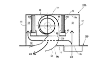
- Patent Document 1 shown in FIG. 4 has an air outlet 14b arranged on the front side and an air suction port 14a arranged on the back side.
- a first heat exchanger 20A as an indoor heat exchanger arranged closer to the front side and a second heat exchanger 20B also arranged closer to the back side as an indoor heat exchanger.
- a sirocco fan 30 arranged between the first heat exchanger 20A and the second heat exchanger 20B, and a first heat exchanger arranged below the first heat exchanger 20A and the second heat exchanger 20B.
- the drain pan 40 that collects the dew condensation water adhering to the 20A and the second heat exchanger 20B, and the outlet air passage 33b and the air outlet 14b so as to guide the air blown from the outlet air passage 33b of the sirocco fan 30 to the air outlet 14b.
- a first space S1 in which an air suction port 14a opens between the second heat exchanger 20B and the back plate 12, and a first heat exchanger 20A and the front plate 11 are provided with a blowout guide 50 for connecting the two.
- a ceiling-embedded air exchanger in which a third space S3 and a second space S2 connected to the first space S1 and the third space S3 are formed between the drain pan 40 and the bottom plate 14.
- a 100A indoor unit is disclosed.
- the first heat exchanger 20A and the second heat exchange are within the limited space of the housing 10. Since the vessel 20B and the sirocco fan 30 must be stored, the distance of the ventilation path from the air suction port 14a to the first heat exchanger 20A via the second space S2 and the third space S3 and the air suction port 14a. The distance of the ventilation path from the air suction port 14a to the second heat exchanger 20B via the first space S1 is not the same, and the first heat exchanger from the air suction port 14a via the second space S2 and the third space S3. The distance of the ventilation path to 20A is longer than the distance of the ventilation path from the air suction port 14a to the second heat exchanger 20B via the first space S1.
- the distance of the ventilation path from the air suction port 14a to the first heat exchanger 20A via the second space S2 and the third space S3 is the first from the air suction port 14a. Since it is longer than the distance of the ventilation path to the second heat exchanger 20B via the first space S1, the first heat exchanger 20A from the air suction port 14a via the second space S2 and the third space S3. Since the ventilation resistance of the ventilation path up to is larger than the ventilation resistance of the ventilation path from the air suction port 14a to the second heat exchanger 20B via the first space S1, the air passing through the first heat exchanger 20A. The amount will be less than the amount of air passing through the second heat exchanger 20B.
- the temperature of the refrigerant flowing through the first heat exchanger 20A becomes higher than the temperature of the refrigerant flowing through the second heat exchanger 20B, so that the temperature sensor required to control the air conditioning chamber to a predetermined temperature is heated to the first heat. It must be provided in each of the exchanger 20A and the second heat exchanger 20B, and there is a problem that the manufacturing cost increases and the control becomes complicated.
- the present invention includes an outdoor unit provided with a compressor and a four-way valve, a plurality of indoor heat exchangers, an indoor unit fan, and a temperature detecting means for detecting the temperature of the indoor heat exchanger. It has an indoor unit to be connected, and at least controls the compressor, the indoor unit fan, and the four-way valve so that the temperature of the indoor heat exchanger becomes a predetermined temperature, and evaporates multiple indoor heat exchangers in the case of cooling.
- an air conditioner that controls the temperature of the room where the indoor unit is installed by functioning as a container and as a condenser in the case of heating, it can be carried out at low cost and disinfecting each of the multiple indoor heat exchangers. It provides an air exchanger that can suppress imbalances.
- One aspect of the present invention includes an outdoor unit provided with a compressor and a four-way valve, a plurality of indoor heat exchangers, an indoor unit fan, and a temperature detecting means for detecting the temperature of the indoor heat exchanger.
- a plurality of indoor heat exchangers are provided by controlling at least the compressor, the indoor unit fan, and the four-way valve so that the temperature of the indoor heat exchanger becomes a predetermined temperature. In the case of cooling, it functions as an evaporator and in the case of heating, it functions as a condenser to control the temperature of the room in which the indoor unit is installed.
- the temperature detecting means is provided in any one of the plurality of indoor heat exchangers while being set to flow to the indoor heat exchanger, and the plurality of indoor heat exchangers function as evaporators.
- the dew condensation water adhering to the indoor heat exchangers is heated to a predetermined temperature by making the plurality of indoor heat exchangers function as condensers, and air harmony is performed to heat sterilize the plurality of indoor heat exchangers. It is a machine.
- the present invention there is a difference between the amount of air passing through one indoor heat exchanger and the amount of air passing through another indoor heat exchanger, and a different amount of refrigerant is used in one indoor heat exchanger according to the difference.
- other indoor heat exchangers are set to flow, and one of the multiple indoor heat exchangers is provided with a temperature detecting means for detecting the temperature of the indoor heat exchanger. It is possible to provide an air conditioner that can be implemented at low cost and can suppress the imbalance of sterilization of each of a plurality of indoor heat exchangers.
- an air conditioner capable of performing cooling operation and heating operation by connecting the indoor unit to the outdoor unit and arranging two indoor heat exchangers in the indoor unit will be described as an example.
- the present invention is not limited to the following embodiments, and various modifications can be made without departing from the gist of the present invention.
- FIG. 1 schematically shows the configuration of the refrigerating circuit of the air conditioner 11 according to the embodiment of the present invention.
- the air conditioner 11 includes an indoor unit 12 and an outdoor unit 13.
- the indoor unit 12 is installed, for example, in an indoor space in a building.
- the indoor unit 12 may be installed in a space corresponding to the indoor space.
- the indoor unit 12 incorporates an indoor heat exchanger 14 as a heat exchanger.
- the outdoor unit 13 incorporates a compressor 15, an outdoor heat exchanger 16, an expansion valve 17, and a four-way valve 18.
- the indoor heat exchanger 14, the compressor 15, the outdoor heat exchanger 16, the expansion valve 17, and the four-way valve 18 form a refrigerating circuit 19.
- the outdoor unit 13 may be installed outdoors so that heat can be exchanged with the outdoor air.
- the refrigeration circuit 19 includes a first circulation path 21.
- the first circulation path 21 connects the first port 18a and the second port 18b of the four-way valve 18 to each other.
- a compressor 15 is provided in the first circulation path 21.
- the suction pipe 15a of the compressor 15 is connected to the first port 18a of the four-way valve 18 via a refrigerant pipe.
- the gas refrigerant is supplied from the first port 18a to the suction pipe 15a of the compressor 15.
- the compressor 15 compresses the low-pressure gas refrigerant to a predetermined pressure.
- the discharge pipe 15b of the compressor 15 is connected to the second port 18b of the four-way valve 18 via a refrigerant pipe.
- the gas refrigerant is supplied from the discharge pipe 15b of the compressor 15 to the second port 18b of the four-way valve 18.
- the refrigerant pipe may be, for example, a copper pipe.
- the four-way valve 18 is used as a flow path switching valve, a plurality of solenoid valves may be combined instead of the four-way valve 18.
- the refrigeration circuit 19 further includes a second circulation path 22.
- the second circulation path 22 connects the third port 18c and the fourth port 18d of the four-way valve 18 to each other.
- the outdoor heat exchanger 16, the expansion valve 17, and the indoor heat exchanger 14 are incorporated in the second circulation path 22 in order from the third port 18c side.
- the outdoor heat exchanger 16 exchanges heat energy between the passing refrigerant and the surrounding air.
- the indoor heat exchanger 14 exchanges heat energy between the passing refrigerant and the surrounding air.
- the indoor heat exchanger 14 is shown as one unit in FIG. 1, as will be described later in the description of FIG. 2, the indoor heat exchanger 14 includes two first heat exchangers 14A and a second heat. It is composed of a exchanger 14B.
- the blower fan 23 is incorporated in the outdoor unit 13.
- the blower fan 23 ventilates the outdoor heat exchanger 16.
- the blower fan 23 generates an air flow according to the rotation of the impeller, for example.
- the airflow passes through the outdoor heat exchanger 16 by the action of the blower fan 23.
- the outdoor air passes through the outdoor heat exchanger 16 and exchanges heat with the refrigerant.
- the heat-exchanged cold or warm air flow is blown out from the outdoor unit 13.
- the flow rate of the airflow passing through is adjusted according to the rotation speed of the impeller.
- the sirocco fan 24 as an indoor unit fan is incorporated in the indoor unit 12.
- the sirocco fan 24 ventilates the indoor heat exchanger 14.
- the sirocco fan 24 generates an air flow according to the rotation of the impeller.
- Indoor air is sucked into the indoor unit 12 by the action of the sirocco fan 24.
- the indoor air passes through the indoor heat exchanger 14 and exchanges heat with the refrigerant.
- the heat-exchanged cold or warm air flow is blown out from the indoor unit 12.
- the flow rate of the airflow passing through is adjusted according to the rotation speed of the impeller.
- the four-way valve 18 connects the second port 18b and the third port 18c to each other, and connects the first port 18a and the fourth port 18d to each other. Therefore, the high-temperature and high-pressure refrigerant is supplied to the outdoor heat exchanger 16 from the discharge pipe 15b of the compressor 15.
- the refrigerant circulates in order through the outdoor heat exchanger 16, the expansion valve 17, and the indoor heat exchanger 14.
- the outdoor heat exchanger 16 dissipates heat from the refrigerant to the outside air.
- the expansion valve 17 reduces the pressure of the refrigerant to a low pressure.
- the decompressed refrigerant absorbs heat from the surrounding air in the indoor heat exchanger 14. Cold air is generated. The cold air is blown into the indoor space by the action of the blower fan 24.
- the four-way valve 18 connects the second port 18b and the fourth port 18d to each other, and connects the first port 18a and the third port 18c to each other.
- a high-temperature and high-pressure refrigerant is supplied from the compressor 15 to the indoor heat exchanger 14.
- the refrigerant flows through the indoor heat exchanger 14, the expansion valve 17, and the outdoor heat exchanger 16 in this order.
- the indoor heat exchanger 14 dissipates heat from the refrigerant to the surrounding air. Warm air is generated. The warm air is blown into the indoor space by the action of the sirocco fan 24.
- the expansion valve 17 reduces the pressure of the refrigerant to a low pressure.
- the decompressed refrigerant absorbs heat from the surrounding air by the outdoor heat exchanger 16. After that, the refrigerant returns to the compressor 15.
- the maximum temperature of the indoor heat exchanger 14 during the heating operation is 53 ° C.
- the air conditioner 11 includes a temperature sensor 26a and a humidity sensor 26b.
- the temperature sensor 26a is connected to the indoor heat exchanger 14.
- the temperature sensor 26a measures the temperature of the indoor heat exchanger 14.
- the temperature sensor 26a outputs a temperature signal including temperature information of the measured temperature.
- the humidity sensor 26b is installed in the indoor unit 12.
- the humidity sensor 26b measures the relative humidity in the indoor unit 12.
- the humidity sensor 26b outputs a humidity signal including humidity information of the measured humidity.
- the air conditioner 11 includes a control unit 27.
- the control unit 27 is formed on, for example, a control board (not shown) incorporated in the outdoor unit 13.
- the four-way valve 18, the expansion valve 17, and the compressor 15 in the outdoor unit 13 are electrically connected to the control unit 27 by individual signal lines.
- the drive motor of the sirocco fan 24 in the indoor unit 12, the temperature sensor 26a, and the humidity sensor 26b are electrically connected to the control unit 27 by individual signal lines.
- the control unit 27 Based on the temperature signal from the temperature sensor 26a and the humidity signal from the humidity sensor 26b, the control unit 27 has a four-way valve 18 in the outdoor unit 13, an expansion valve 17 and a compressor 15, and a sirocco fan 24 in the indoor unit 12. Control the operation of.
- the control unit 27 can control the operation of the sirocco fan 24 during the cooling operation or the heating operation based on the operation signal input from the remote controller to the indoor unit 12 to change the air volume of the cold air or the warm air.
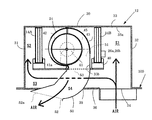
- FIG. 3 schematically shows a cross section of the indoor unit 12 according to the embodiment.
- the indoor unit 12 is an indoor unit of a ceiling-embedded air conditioner, and is installed behind the ceiling 100 in the room.
- the indoor unit 12 is entirely surrounded by a housing 30.
- the housing 30 includes a front plate 31, a back plate 32, a top plate 33, a bottom plate 36 having an air suction port 34 and an air outlet 35, a left side plate (not shown) provided on the back side of the paper surface of FIG. 3, and FIG.
- a flat plate-shaped first heat exchanger 14A is attached to the side of the front plate 11 of the lower surface 33a of the top plate 33 in a posture perpendicular to the top plate 33. Further, a flat plate-shaped second heat exchanger 14B is similarly attached to the side of the back plate 32 of the lower surface 33a of the top plate 33 in a posture perpendicular to the top plate 33.
- a sirocco fan 24 is arranged between the first heat exchanger 14A and the second heat exchanger 14B.
- the sirocco fan 24 has a fan motor 41, an impeller 42 fixed to the rotating shaft 41a of the fan motor 41, and a suction port 44 leading to the impeller 42 on the side surface, and faces the outer peripheral surface of the impeller 42 on the lower surface. It has a fan casing 43 in which a blowout air passage 45 is formed. Under the first heat exchanger 14A and the second heat exchanger 14B, a drain pan 40 for collecting the condensed water generated in the first heat exchanger 14A and the second heat exchanger 14B is arranged.
- a first space S1 that functions as a ventilation path is formed between the second heat exchanger 14B and the back plate 32, and an air suction port 34 is provided in the first space S1. It is directly open. Further, a second space S2 that functions as a ventilation path is also formed between the first heat exchanger 14A and the front plate 31, and further functions as a ventilation path between the drain pan 40 and the bottom plate 36. A third space S3 connected to the first space S1 and the second space S2 is formed.
- the air suction port 34 is arranged on the side of the back plate 32 of the bottom plate 36, and the air outlet 35 is arranged on the side of the front plate 31 with respect to the air suction port 34 of the bottom plate 36. Therefore, the distance of the ventilation path from the air suction port 34 to the first heat exchanger 14A via the third space S3 and the second space S2 is from the air suction port 34 via the first space S1. It is longer than the distance of the ventilation path to the second heat exchanger 14B by the amount of the third space S3.
- the distance of the ventilation path from the air suction port 34 where the first heat exchanger 14A is arranged to the air outlet 35 is from the air suction port 34 where the second heat exchanger 14B is arranged to the air outlet 35. Since it is longer than the distance of the ventilation passage, the ventilation resistance of the ventilation passage in which the first heat exchanger 14A is arranged is larger than the ventilation resistance of the ventilation passage in which the second heat exchanger 14B is arranged. It has become.
- the blowout air passage 45 of the sirocco fan 24 is connected to the upper end opening 51 of the blowout guide 50 inserted into the air outlet 35 of the bottom plate 36.
- the blowout guide 50 is formed so that the air guide path S4 between the upper end opening 51 and the lower end opening 52 is curved downward toward the front, and the opening surface 52a of the lower end opening 52 faces the front of the lower surface of the front plate 11. It is arranged like. Further, the outlet guide 50 penetrates the outlet 53 of the drain pan 40 and the air outlet 35 of the bottom plate 36, and the lower end opening 52 of the outlet guide 50 becomes a substantial air outlet.
- the air suction port 34 of the bottom plate 36 is provided between the air outlet opening 35 and the back plate 12.
- the indoor unit 12 enters the second heat exchanger 14B from the air suction port 34 via the first space S1 between the second heat exchanger 14B and the back plate 12.
- air is introduced into the first heat exchanger 14A via the second space S2 between the bottom plate 36 and the drain pan 40 and the third space S3 between the front plate 31 and the first heat exchanger 14A. Inhale.
- the air sucked into the sirocco fan 24 after being heat-exchanged with the refrigerant in the first heat exchanger 14A and the second heat exchanger 14B passes through the blow-out air passage 45 of the fan casing 43 to the air guide passage S4 of the blow-out guide 50. It is blown out downward and forward of the front plate 31 via the air.
- the structure of the indoor heat exchanger 14 of the present embodiment is schematically shown.
- the indoor heat exchanger 14 is expanded by connecting the first heat exchanger 14A and the second heat exchanger 14B in parallel between the four-way valve 18 and the expansion valve 17.
- the refrigerant pipe from the valve 17 is connected via the distributor 60, and the refrigerant pipe from the four-way valve 18 is connected via the header 61.
- the distributor 60 has a function of dividing the refrigerant flowing from the expansion valve 17 into the first heat exchanger 14A and the second heat exchanger 14B, or flows from the first heat exchanger 14A and the second heat exchanger 14B. It has a function of merging the incoming refrigerant and flowing it to the expansion valve 17.
- the header 61 has a function of merging the refrigerants flowing from the first heat exchanger 14A and the second heat exchanger 14B and flowing them to the four-way valve 18, or the first heat exchanger using the refrigerant flowing from the four-way valve 18. It has a function of dividing the flow into 14A and the second heat exchanger 14B.
- Each of the first heat exchanger 14A and the second heat exchanger 14B has paths as pipes through which a plurality of refrigerants flow, and in the present embodiment, the first heat exchanger 14A has three paths 14A1.
- the second heat exchanger 14B has five paths 14B1. Therefore, the amount of refrigerant flowing through the first heat exchanger 14A and the amount of refrigerant flowing through the second heat exchanger 14B are different, and the amount of refrigerant flowing through the second heat exchanger 14B is larger than the amount of refrigerant flowing through the first heat exchanger 14A. There are more.
- the number of paths 14A1 of the first heat exchanger 14A and the number of paths 14B1 of the second heat exchanger 14B are the amount of air sucked into the first heat exchanger 14A by the sirocco fan 24 and the second heat exchange. It is determined according to the difference in the amount of air sucked into the container 14B, and in the present embodiment, the amount of air sucked into the first heat exchanger 14A is smaller than the amount of air sucked into the second heat exchanger 14B. Therefore, the number of paths 14A1 of the first heat exchanger 14A is smaller than the number of paths 14B1 of the second heat exchanger 14B.
- the amount of air flowing through the first heat exchanger 14A and the amount of air flowing through the second heat exchanger 14B are different from each other with two indoor heat exchangers 14 as in the present embodiment.
- the first heat is determined by determining the number of paths 14A1 constituting the first heat exchanger 14A and the number of paths 14B1 constituting the second heat exchanger 14B according to the difference in the amount of flowing air.
- the imbalance between the temperature of the refrigerant flowing through the exchanger 14A and the temperature of the refrigerant flowing through the second heat exchanger 14B can be improved.
- the temperatures of the heat exchangers 14A and 14B can both be set to a predetermined temperature (for example, 55 ° C.).
- the distance of the ventilation path from the air suction port 34 to the first heat exchanger 14A is longer than the distance of the ventilation path from the air suction port 34 to the second heat exchanger 14B.
- the ventilation resistance of the ventilation path from the air suction port 34 to the first heat exchanger 14A is larger than the ventilation resistance of the ventilation path of the ventilation path from the air suction port 34 to the second heat exchanger 14B, but the ventilation resistance Is affected not only by the length of the ventilation passage, but also by the cross-sectional area of the ventilation passage, the shape inside the ventilation passage, the friction coefficient of the inner surface of the ventilation passage, and the like.
- the first heat exchanger corresponds to the ventilation resistance of the ventilation path from the air suction port 34 to the first heat exchanger 14A and the ventilation resistance of the ventilation path from the air suction port 34 to the second heat exchanger 14B.
- the number of paths 14A1 constituting 14A and the number of paths 14B1 constituting the second heat exchanger 14B may be determined.
- ventilation from each of the indoor heat exchangers 14A and 14B to the air outlet 35 is determined.
- the air suction port including the ventilation passage from each of the indoor heat exchangers 14A and 14B to the air outlet 35 It is necessary to consider the ventilation resistance of the ventilation path from 34 to the air outlet 35.
- the indoor heat exchanger 14 is composed of two units, a first heat exchanger 14A and a second heat exchanger 14B.
- the humidity sensor 26b for measuring humidity does not need to be attached to each of the first heat exchanger 14A and the second heat exchanger 14B, but is attached to either the first heat exchanger 14A or the second heat exchanger 14B. It suffices if it is done.
- the distance of the ventilation path from the air suction port 34 to the first heat exchanger 14A and the distance of the ventilation path from the air suction port 34 to the second heat exchanger 14B are different.
- the temperature of the refrigerant flowing through the first heat exchanger 14A and the second heat exchanger 14B This is because it is not necessary to attach the temperature sensor 26a to each of the first heat exchanger 14A and the second heat exchanger 14B because imbalance with the temperature of the refrigerant flowing through the heat exchanger is unlikely to occur.
- the temperature sensor 26a and the humidity sensor 26b are the surfaces on the first space S1 side of the second heat exchanger 14B and are arranged on the lower side. Since the first space S1 opens directly to the air suction port 34, if the temperature sensor 26a is arranged on the lower side of the surface of the second heat exchanger 14B on the first space S1 side, the temperature sensor 26a This is because when the humidity sensor 26b is maintained and inspected, it can be easily inspected from the air suction port 34.
- the air conditioner 11 of the present embodiment has the first heat exchanger 14A and the second heat exchanger 14B by making the first heat exchanger 14A and the second heat exchanger 14B function as evaporators by the cooling operation.
- the first heat exchanger 14A and the second heat exchanger 14B function as condensers and controlling the rotation speed of the sirocco fan 24, the dew condensation water adheres to the first heat exchanger 14A and the second heat.
- a heat sterilization operation is performed in which the temperature of the exchanger 14B is heated in a temperature range different from that of the heating operation.
- the first heat exchanger 14A and the second heat are driven by driving the rotation speed of the sirocco fan 24 at a rotation speed lower than the rotation speed in the case of the heating operation without aiming at the temperature control in the room.
- the rotation speed of the sirocco fan 24 is, for example, about 500 rpm to 1000 rpm, but in the case of heat sterilization operation, the rotation speed of the sirocco fan 24 is about 200 rpm.
- the pressure of the high-pressure side refrigerant can be increased to maintain the temperatures of the first heat exchanger 14A and the second heat exchanger 14B at 55 ° C to 59 ° C. it can.
- the first heat exchanger 14A and the second heat exchanger 14B function as evaporators, dew condensation adheres to the first heat exchanger 14A and the second heat exchanger 14B.
- the first heat exchanger 14A and the second heat exchanger 14B function as condensers and heating the water at 55 to 59 ° C., which is a temperature range different from the heating operation, the water is heated with the first heat exchanger 14A. Since the second heat exchanger 14B is heat-sterilized, the sterilization can be carried out at low cost without providing a dedicated device, and the sterilization can be performed even when the inside of the indoor unit 12 is in a high humidity state.
- the first heat exchanger 14A flows even in the state of heat sterilization operation. Since the imbalance between the temperature of the refrigerant and the temperature of the refrigerant flowing through the second heat exchanger 14B can be suppressed, the imbalance of sterilization of the first heat exchanger 14A and the second heat exchanger 14B can be suppressed. Can be done.
Landscapes
- Engineering & Computer Science (AREA)
- Chemical & Material Sciences (AREA)
- Combustion & Propulsion (AREA)
- Mechanical Engineering (AREA)
- General Engineering & Computer Science (AREA)
- Physics & Mathematics (AREA)
- Thermal Sciences (AREA)
- Air Filters, Heat-Exchange Apparatuses, And Housings Of Air-Conditioning Units (AREA)
- Air Conditioning Control Device (AREA)
- Air-Conditioning Room Units, And Self-Contained Units In General (AREA)
Abstract
Description
また、空気調和機には、屋外に設置される室外機と空調室内に設置される室内機とが冷媒配管で接続されており、室内機として天井裏に設置される天井埋込型のもの(以下、天井埋込型空気調和機と言う。)があるが、近年、天井埋込型空気調和機として熱交換容量を増大させることが望まれている。
尚、四方弁18は流路切換弁として用いているが、四方弁18ではなく電磁弁を複数組み合わせても構わない。
尚、図1において、室内熱交換器14は1台で示されているが、図2の説明で後述するように室内熱交換器14は、2台の第1熱交換器14Aと第2熱交換器14Bとで構成されている。
第1熱交換器14A及び第2熱交換器14Bの下には、それら第1熱交換器14A及び第2熱交換器14Bで生じた結露水を集めるドレンパン40が配置されている。
冷凍回路の19において、室内熱交換器14は、四方弁18と膨張弁17との間に第1熱交換器14Aと第2熱交換器14Bとが並列になるように接続されており、膨張弁17からの冷媒配管とはディストリビュータ60を介して接続し、四方弁18からの冷媒配管とはヘッダ61を介して接続している。ディストリビュータ60は、膨張弁17から流れてきた冷媒を第1熱交換器14Aと第2熱交換器14Bとへ分流させる機能を、あるいは、第1熱交換器14Aと第2熱交換器14Bから流れてきた冷媒を合流させて膨張弁17へと流す機能を有している。ヘッダ61は、第1熱交換器14Aと第2熱交換器14Bから流れてきた冷媒を合流させて四方弁18へと流す機能、あるいは、四方弁18から流れてきた冷媒を第1熱交換器14Aと第2熱交換器14Bとへ分流させる機能を有している。
従って、第1熱交換器14Aを流れる冷媒量と第2熱交換器14Bを流れる冷媒量は異なっており、第1熱交換器14Aを流れる冷媒量よりも第2熱交換器14B流れる冷媒量の方が多くなる。
これにより、各熱交換器14A、14Bを加熱除菌する場合に、各熱交換器14A、14Bの温度を共に所定温度(例えば、55℃)とすることができる。
尚、第1熱交換器14Aを構成するパス14A1の数と第2熱交換器14Bを構成するパス14B1の数を決める場合、各室内熱交換器14A、14Bそれぞれから空気吹出口35までの通風路の通風抵抗も、各室内熱交換器14A、14Bそれぞれに吸い込まれる空気の量に影響するため、各室内熱交換器14A、14Bそれぞれから空気吹出口35までの通風路も含め、空気吸入口34から空気吹出口35までの通風路の通風抵抗について考慮する必要がある。
Claims (4)
- 圧縮機と四方弁を備えた室外機と、複数の室内熱交換器と室内機ファンと前記室内熱交換器の温度を検出する温度検出手段とを含み前記室外機に接続する室内機と、を有し、前記室内熱交換器の温度が所定温度になるように、少なくとも前記圧縮機と前記室内機ファンと前記四方弁を制御して複数の前記室内熱交換器を冷房の場合は蒸発器として機能させると共に暖房の場合は凝縮器として機能させて、前記室内機が設置された室内の温調を行う空気調和機において、
前記室内機ファンによる送風によって、一の前記室内熱交換器を通過する空気量と他の前記室内熱交換器を通過する空気量とに相違があり、前記空気量の相違に応じて異なる冷媒量を一の前記室内熱交換器と他の前記室内熱交換器とに流すように設定すると共に複数の前記室内熱交換器のいずれか一の室内熱交換器に前記温度検出手段を設けて、
複数の前記室内熱交換器が蒸発器として機能した場合に前記室内熱交換器に付着した結露水を、複数の前記室内熱交換器を凝縮器として機能させて所定温度まで加熱させ、複数の前記室内熱交換器の加熱除菌を行うことを特徴とする空気調和機。 - 前記室内機は、空気吸込口と空気吹出口とを有すると共にそれら空気吸込口と空気吹出口との間に互いに並列関係にある複数の通風路を有する筐体と、前記複数の通風路のそれぞれに配置された少なくとも1つの前記室内熱交換器と、前記空気吸込口から吸い込んだ空気を前記複数の通風路のそれぞれを経由して前記空気吹出口へ導く前記室内機ファンと、を備えて、
一の前記通風路の通風抵抗は、他の前記通風路の通風抵抗よりも大きく、前記通風抵抗の大小に応じて前記一の通風路に配置された一の前記室内熱交換器を流れる冷媒量は、前記他の通風路に配置された他の前記室内熱交換器を流れる冷媒量よりも少なく設定されていることを特徴とする請求項1に記載の空気調和機。 - 前記筐体は、前面板、背面板、天面板、底面板、左側面板、及び右側面板を有する箱型であり、
前記底面板は、前記前面板側に配置された前記空気吹出口及び前記背面板側に配置された前記空気吸込口を有し、
複数の前記室内熱交換器は、前記筐体内の前記前面板寄りに取り付けられる前記一の室内熱交換器としての第1熱交換器と、前記背面板寄りに取り付けられる前記他の室内熱交換器としての第2熱交換器を含み、
前記室内機ファンは、吹出通風路を有し、前記第1熱交換器と前記第2熱交換器の間の位置に配置され、
前記第1熱交換器及び前記第2熱交換器の下側に配置されて、前記第1熱交換器と前記第2熱交換器に付着した結露水を集めるドレンパンと、
前記室内機ファンの前記吹出通風路から吹き出される空気を前記空気吹出口にガイドするよう前記吹出通風路と前記空気吹出口とをつなぐ吹出ガイドと、を備え、
前記第2熱交換器と前記背面板との間に、前記空気吸込口が開口する第1スペースを形成し、前記第1熱交換器と前記前面板との間に第2スペースを形成し、前記ドレンパンと前記底面板との間に前記第1スペースと前記第2スペースとを接続させる第3スペースを形成して、
前記空気吸込口から前記第3スペース及び前記第2スペースを経由して前記第1熱交換器までの通風路の通風抵抗が、前記空気吸込口から前記第1スペースを経由して前記第2熱交換器までの通風路の通風抵抗より大きくなるように、前記第1熱交換器と前記第2熱交換器が配置されていることを特徴とする請求項2に記載の空気調和機。 - 前記温度検出手段は、前記第2熱交換器の下部側であって第1スペース側に配置されていることを特徴とする請求項3に記載の空気調和機。
Priority Applications (2)
| Application Number | Priority Date | Filing Date | Title |
|---|---|---|---|
| CN202080085187.3A CN114867968B (zh) | 2019-12-23 | 2020-12-23 | 空调机 |
| EP20905074.9A EP4083530B1 (en) | 2019-12-23 | 2020-12-23 | Air conditioner |
Applications Claiming Priority (2)
| Application Number | Priority Date | Filing Date | Title |
|---|---|---|---|
| JP2019231288A JP7031651B2 (ja) | 2019-12-23 | 2019-12-23 | 空気調和機 |
| JP2019-231288 | 2019-12-23 |
Publications (1)
| Publication Number | Publication Date |
|---|---|
| WO2021132413A1 true WO2021132413A1 (ja) | 2021-07-01 |
Family
ID=76541272
Family Applications (1)
| Application Number | Title | Priority Date | Filing Date |
|---|---|---|---|
| PCT/JP2020/048319 Ceased WO2021132413A1 (ja) | 2019-12-23 | 2020-12-23 | 空気調和機 |
Country Status (4)
| Country | Link |
|---|---|
| EP (1) | EP4083530B1 (ja) |
| JP (1) | JP7031651B2 (ja) |
| CN (1) | CN114867968B (ja) |
| WO (1) | WO2021132413A1 (ja) |
Citations (4)
| Publication number | Priority date | Publication date | Assignee | Title |
|---|---|---|---|---|
| JP2001174047A (ja) * | 1999-12-17 | 2001-06-29 | Matsushita Electric Ind Co Ltd | 空気調和機の室内機 |
| JP2002162052A (ja) * | 2000-11-20 | 2002-06-07 | Daikin Ind Ltd | 空気調和機および室内熱交換器 |
| JP2018119718A (ja) * | 2017-01-24 | 2018-08-02 | 株式会社富士通ゼネラル | 天井埋込型空気調和機 |
| WO2018159446A1 (ja) * | 2017-02-28 | 2018-09-07 | 株式会社富士通ゼネラル | 空気調和機 |
Family Cites Families (13)
| Publication number | Priority date | Publication date | Assignee | Title |
|---|---|---|---|---|
| JP4160678B2 (ja) * | 1999-01-04 | 2008-10-01 | 東芝キヤリア株式会社 | 空気調和機 |
| JP3589184B2 (ja) | 2001-01-11 | 2004-11-17 | ダイキン工業株式会社 | 空気調和機の室内機 |
| JP4700513B2 (ja) | 2006-02-13 | 2011-06-15 | 東芝キヤリア株式会社 | 空気調和機の室内機 |
| AU2007303268B2 (en) * | 2006-09-29 | 2011-02-10 | Daikin Industries, Ltd. | Indoor unit for air conditioner |
| JP6411238B2 (ja) | 2015-02-23 | 2018-10-24 | 日立ジョンソンコントロールズ空調株式会社 | 空気調和機 |
| JP2016200338A (ja) | 2015-04-13 | 2016-12-01 | ジョンソンコントロールズ ヒタチ エア コンディショニング テクノロジー(ホンコン)リミテッド | 空気調和機 |
| JP2018004131A (ja) * | 2016-06-30 | 2018-01-11 | 株式会社富士通ゼネラル | 空気調和機 |
| JP6824779B2 (ja) * | 2017-02-28 | 2021-02-03 | 株式会社富士通ゼネラル | 空気調和機の防カビ方法およびそれを用いた空気調和機 |
| JP2018189251A (ja) | 2017-04-28 | 2018-11-29 | 株式会社富士通ゼネラル | 天井埋込型空気調和機の室内機 |
| JP2019066066A (ja) | 2017-09-29 | 2019-04-25 | ダイキン工業株式会社 | 空気調和機 |
| JP6737303B2 (ja) | 2018-03-30 | 2020-08-05 | 株式会社富士通ゼネラル | 天井埋込型空気調和機 |
| JP7049600B2 (ja) | 2018-03-30 | 2022-04-07 | 株式会社富士通ゼネラル | 天井埋込型空気調和機 |
| JP2019203629A (ja) | 2018-05-22 | 2019-11-28 | 株式会社富士通ゼネラル | 天井埋込型空気調和機 |
-
2019
- 2019-12-23 JP JP2019231288A patent/JP7031651B2/ja active Active
-
2020
- 2020-12-23 CN CN202080085187.3A patent/CN114867968B/zh active Active
- 2020-12-23 EP EP20905074.9A patent/EP4083530B1/en active Active
- 2020-12-23 WO PCT/JP2020/048319 patent/WO2021132413A1/ja not_active Ceased
Patent Citations (4)
| Publication number | Priority date | Publication date | Assignee | Title |
|---|---|---|---|---|
| JP2001174047A (ja) * | 1999-12-17 | 2001-06-29 | Matsushita Electric Ind Co Ltd | 空気調和機の室内機 |
| JP2002162052A (ja) * | 2000-11-20 | 2002-06-07 | Daikin Ind Ltd | 空気調和機および室内熱交換器 |
| JP2018119718A (ja) * | 2017-01-24 | 2018-08-02 | 株式会社富士通ゼネラル | 天井埋込型空気調和機 |
| WO2018159446A1 (ja) * | 2017-02-28 | 2018-09-07 | 株式会社富士通ゼネラル | 空気調和機 |
Non-Patent Citations (1)
| Title |
|---|
| See also references of EP4083530A4 * |
Also Published As
| Publication number | Publication date |
|---|---|
| CN114867968B (zh) | 2025-01-28 |
| CN114867968A (zh) | 2022-08-05 |
| JP7031651B2 (ja) | 2022-03-08 |
| JP2021099192A (ja) | 2021-07-01 |
| EP4083530A4 (en) | 2024-01-24 |
| EP4083530B1 (en) | 2026-04-15 |
| EP4083530A1 (en) | 2022-11-02 |
Similar Documents
| Publication | Publication Date | Title |
|---|---|---|
| US11137148B2 (en) | Air conditioner | |
| KR102232441B1 (ko) | 육구 공조기 | |
| US20210108805A1 (en) | Air conditioner ventilation device and air conditioner ventilation method | |
| KR101497698B1 (ko) | 공기조화시스템 | |
| KR102139084B1 (ko) | 공기 조화기 | |
| JP5916346B2 (ja) | 空調設備 | |
| CN114667421A (zh) | 空调装置 | |
| JP7457229B2 (ja) | 空気調和システム | |
| JP7031650B2 (ja) | 空気調和機 | |
| JP7260827B2 (ja) | 換気装置及び空気調和システム | |
| WO2007123144A1 (ja) | 換気システム | |
| US6272880B1 (en) | Air conditioner | |
| JP7031651B2 (ja) | 空気調和機 | |
| KR102246320B1 (ko) | 공기 조화 시스템 | |
| JP2023035012A (ja) | 空気調和システム | |
| JP2018025337A (ja) | 空調機 | |
| JP3855393B2 (ja) | 空気調和装置 | |
| JP7189472B2 (ja) | 空調システム | |
| WO2023053712A1 (ja) | 換気装置及び空気調和システム | |
| JP2004226012A (ja) | ダクト式空気調和機 | |
| JP2007333378A (ja) | ヒートポンプ式空調機 | |
| JP7461409B2 (ja) | 空気調和装置 | |
| JP2020186821A (ja) | 空気調和システム | |
| US20240393002A1 (en) | Air conditioner | |
| JP4099718B2 (ja) | ヒートポンプ式空調機 |
Legal Events
| Date | Code | Title | Description |
|---|---|---|---|
| 121 | Ep: the epo has been informed by wipo that ep was designated in this application |
Ref document number: 20905074 Country of ref document: EP Kind code of ref document: A1 |
|
| NENP | Non-entry into the national phase |
Ref country code: DE |
|
| ENP | Entry into the national phase |
Ref document number: 2020905074 Country of ref document: EP Effective date: 20220725 |
|
| WWG | Wipo information: grant in national office |
Ref document number: 202080085187.3 Country of ref document: CN |
|
| WWG | Wipo information: grant in national office |
Ref document number: 2020905074 Country of ref document: EP |