WO2021132476A1 - R-t-b系焼結磁石の製造方法およびr-t-b系焼結磁石 - Google Patents
R-t-b系焼結磁石の製造方法およびr-t-b系焼結磁石 Download PDFInfo
- Publication number
- WO2021132476A1 WO2021132476A1 PCT/JP2020/048486 JP2020048486W WO2021132476A1 WO 2021132476 A1 WO2021132476 A1 WO 2021132476A1 JP 2020048486 W JP2020048486 W JP 2020048486W WO 2021132476 A1 WO2021132476 A1 WO 2021132476A1
- Authority
- WO
- WIPO (PCT)
- Prior art keywords
- based sintered
- rtb
- sintered magnet
- rare earth
- ppm
- Prior art date
- Legal status (The legal status is an assumption and is not a legal conclusion. Google has not performed a legal analysis and makes no representation as to the accuracy of the status listed.)
- Ceased
Links
Images
Classifications
-
- B—PERFORMING OPERATIONS; TRANSPORTING
- B22—CASTING; POWDER METALLURGY
- B22F—WORKING METALLIC POWDER; MANUFACTURE OF ARTICLES FROM METALLIC POWDER; MAKING METALLIC POWDER; APPARATUS OR DEVICES SPECIALLY ADAPTED FOR METALLIC POWDER
- B22F3/00—Manufacture of workpieces or articles from metallic powder characterised by the manner of compacting or sintering; Apparatus specially adapted therefor ; Presses and furnaces
-
- B—PERFORMING OPERATIONS; TRANSPORTING
- B22—CASTING; POWDER METALLURGY
- B22F—WORKING METALLIC POWDER; MANUFACTURE OF ARTICLES FROM METALLIC POWDER; MAKING METALLIC POWDER; APPARATUS OR DEVICES SPECIALLY ADAPTED FOR METALLIC POWDER
- B22F1/00—Metallic powder; Treatment of metallic powder, e.g. to facilitate working or to improve properties
-
- B—PERFORMING OPERATIONS; TRANSPORTING
- B22—CASTING; POWDER METALLURGY
- B22F—WORKING METALLIC POWDER; MANUFACTURE OF ARTICLES FROM METALLIC POWDER; MAKING METALLIC POWDER; APPARATUS OR DEVICES SPECIALLY ADAPTED FOR METALLIC POWDER
- B22F3/00—Manufacture of workpieces or articles from metallic powder characterised by the manner of compacting or sintering; Apparatus specially adapted therefor ; Presses and furnaces
- B22F3/24—After-treatment of workpieces or articles
-
- B—PERFORMING OPERATIONS; TRANSPORTING
- B22—CASTING; POWDER METALLURGY
- B22F—WORKING METALLIC POWDER; MANUFACTURE OF ARTICLES FROM METALLIC POWDER; MAKING METALLIC POWDER; APPARATUS OR DEVICES SPECIALLY ADAPTED FOR METALLIC POWDER
- B22F9/00—Making metallic powder or suspensions thereof
- B22F9/02—Making metallic powder or suspensions thereof using physical processes
- B22F9/04—Making metallic powder or suspensions thereof using physical processes starting from solid material, e.g. by crushing, grinding or milling
-
- C—CHEMISTRY; METALLURGY
- C22—METALLURGY; FERROUS OR NON-FERROUS ALLOYS; TREATMENT OF ALLOYS OR NON-FERROUS METALS
- C22C—ALLOYS
- C22C38/00—Ferrous alloys, e.g. steel alloys
- C22C38/005—Ferrous alloys, e.g. steel alloys containing rare earths, i.e. Sc, Y, Lanthanides
-
- H—ELECTRICITY
- H01—ELECTRIC ELEMENTS
- H01F—MAGNETS; INDUCTANCES; TRANSFORMERS; SELECTION OF MATERIALS FOR THEIR MAGNETIC PROPERTIES
- H01F1/00—Magnets or magnetic bodies characterised by the magnetic materials therefor; Selection of materials for their magnetic properties
- H01F1/01—Magnets or magnetic bodies characterised by the magnetic materials therefor; Selection of materials for their magnetic properties of inorganic materials
- H01F1/03—Magnets or magnetic bodies characterised by the magnetic materials therefor; Selection of materials for their magnetic properties of inorganic materials characterised by their coercivity
- H01F1/032—Magnets or magnetic bodies characterised by the magnetic materials therefor; Selection of materials for their magnetic properties of inorganic materials characterised by their coercivity of hard-magnetic materials
- H01F1/04—Magnets or magnetic bodies characterised by the magnetic materials therefor; Selection of materials for their magnetic properties of inorganic materials characterised by their coercivity of hard-magnetic materials metals or alloys
- H01F1/047—Alloys characterised by their composition
- H01F1/053—Alloys characterised by their composition containing rare earth metals
- H01F1/055—Alloys characterised by their composition containing rare earth metals and magnetic transition metals, e.g. SmCo5
- H01F1/057—Alloys characterised by their composition containing rare earth metals and magnetic transition metals, e.g. SmCo5 and IIIa elements, e.g. Nd2Fe14B
- H01F1/0571—Alloys characterised by their composition containing rare earth metals and magnetic transition metals, e.g. SmCo5 and IIIa elements, e.g. Nd2Fe14B in the form of particles, e.g. rapid quenched powders or ribbon flakes
- H01F1/0575—Alloys characterised by their composition containing rare earth metals and magnetic transition metals, e.g. SmCo5 and IIIa elements, e.g. Nd2Fe14B in the form of particles, e.g. rapid quenched powders or ribbon flakes pressed, sintered or bonded together
- H01F1/0577—Alloys characterised by their composition containing rare earth metals and magnetic transition metals, e.g. SmCo5 and IIIa elements, e.g. Nd2Fe14B in the form of particles, e.g. rapid quenched powders or ribbon flakes pressed, sintered or bonded together sintered
-
- H—ELECTRICITY
- H01—ELECTRIC ELEMENTS
- H01F—MAGNETS; INDUCTANCES; TRANSFORMERS; SELECTION OF MATERIALS FOR THEIR MAGNETIC PROPERTIES
- H01F41/00—Apparatus or processes specially adapted for manufacturing or assembling magnets, inductances or transformers; Apparatus or processes specially adapted for manufacturing materials characterised by their magnetic properties
- H01F41/02—Apparatus or processes specially adapted for manufacturing or assembling magnets, inductances or transformers; Apparatus or processes specially adapted for manufacturing materials characterised by their magnetic properties for manufacturing cores, coils, or magnets
- H01F41/0253—Apparatus or processes specially adapted for manufacturing or assembling magnets, inductances or transformers; Apparatus or processes specially adapted for manufacturing materials characterised by their magnetic properties for manufacturing cores, coils, or magnets for manufacturing permanent magnets
- H01F41/0266—Moulding; Pressing
-
- H—ELECTRICITY
- H01—ELECTRIC ELEMENTS
- H01F—MAGNETS; INDUCTANCES; TRANSFORMERS; SELECTION OF MATERIALS FOR THEIR MAGNETIC PROPERTIES
- H01F41/00—Apparatus or processes specially adapted for manufacturing or assembling magnets, inductances or transformers; Apparatus or processes specially adapted for manufacturing materials characterised by their magnetic properties
- H01F41/02—Apparatus or processes specially adapted for manufacturing or assembling magnets, inductances or transformers; Apparatus or processes specially adapted for manufacturing materials characterised by their magnetic properties for manufacturing cores, coils, or magnets
- H01F41/0253—Apparatus or processes specially adapted for manufacturing or assembling magnets, inductances or transformers; Apparatus or processes specially adapted for manufacturing materials characterised by their magnetic properties for manufacturing cores, coils, or magnets for manufacturing permanent magnets
- H01F41/0293—Apparatus or processes specially adapted for manufacturing or assembling magnets, inductances or transformers; Apparatus or processes specially adapted for manufacturing materials characterised by their magnetic properties for manufacturing cores, coils, or magnets for manufacturing permanent magnets diffusion of rare earth elements, e.g. Tb, Dy or Ho, into permanent magnets
-
- B—PERFORMING OPERATIONS; TRANSPORTING
- B22—CASTING; POWDER METALLURGY
- B22F—WORKING METALLIC POWDER; MANUFACTURE OF ARTICLES FROM METALLIC POWDER; MAKING METALLIC POWDER; APPARATUS OR DEVICES SPECIALLY ADAPTED FOR METALLIC POWDER
- B22F1/00—Metallic powder; Treatment of metallic powder, e.g. to facilitate working or to improve properties
- B22F1/05—Metallic powder characterised by the size or surface area of the particles
-
- B—PERFORMING OPERATIONS; TRANSPORTING
- B22—CASTING; POWDER METALLURGY
- B22F—WORKING METALLIC POWDER; MANUFACTURE OF ARTICLES FROM METALLIC POWDER; MAKING METALLIC POWDER; APPARATUS OR DEVICES SPECIALLY ADAPTED FOR METALLIC POWDER
- B22F9/00—Making metallic powder or suspensions thereof
- B22F9/02—Making metallic powder or suspensions thereof using physical processes
- B22F9/04—Making metallic powder or suspensions thereof using physical processes starting from solid material, e.g. by crushing, grinding or milling
- B22F2009/044—Making metallic powder or suspensions thereof using physical processes starting from solid material, e.g. by crushing, grinding or milling by jet milling
-
- B—PERFORMING OPERATIONS; TRANSPORTING
- B22—CASTING; POWDER METALLURGY
- B22F—WORKING METALLIC POWDER; MANUFACTURE OF ARTICLES FROM METALLIC POWDER; MAKING METALLIC POWDER; APPARATUS OR DEVICES SPECIALLY ADAPTED FOR METALLIC POWDER
- B22F2998/00—Supplementary information concerning processes or compositions relating to powder metallurgy
- B22F2998/10—Processes characterised by the sequence of their steps
-
- B—PERFORMING OPERATIONS; TRANSPORTING
- B22—CASTING; POWDER METALLURGY
- B22F—WORKING METALLIC POWDER; MANUFACTURE OF ARTICLES FROM METALLIC POWDER; MAKING METALLIC POWDER; APPARATUS OR DEVICES SPECIALLY ADAPTED FOR METALLIC POWDER
- B22F2999/00—Aspects linked to processes or compositions used in powder metallurgy
Definitions
- the present application relates to a method for manufacturing an RTB-based sintered magnet and an RTB-based sintered magnet.
- RTB-based sintered magnet (R is a rare earth element and always contains at least one selected from the group consisting of Nd, Pr and Ce, and T is at least one of the transition metals and always contains Fe. , B is boron) is the main phase of a compound having an R 2 Fe 14 B type crystal structure, the grain boundary phase located at the grain boundary portion of this main phase, and a compound produced by the influence of trace additive elements and impurities. are composed of a phase, high residual magnetic flux density B r (hereinafter, sometimes simply referred to as "B r") and high coercivity H cJ (hereinafter, sometimes simply referred to as "H cJ”) It is known as the most high-performance magnet among permanent magnets because it has excellent magnetic properties. Therefore, it is used in a wide variety of applications such as various motors such as voice coil motors (VCM) for hard disk drives, motors for electric vehicles (EV, HV, PHV), motors for industrial equipment, and home appliances.
- VCM voice coil motors
- Such an RTB-based sintered magnet is manufactured through, for example, a step of preparing an alloy powder, a step of press-molding the alloy powder to produce a powder molded body, and a step of sintering the powder molded body.
- the alloy powder is produced, for example, by the following method.
- an alloy is produced from molten metal of various raw material metals by a method such as an ingot method or a strip casting method.
- the obtained alloy is subjected to a pulverization step to obtain an alloy powder having a predetermined particle size distribution.
- This pulverization step usually includes a coarse pulverization step and a fine pulverization step.
- the former is carried out by using, for example, a hydrogen embrittlement phenomenon, and the latter is carried out by using, for example, an airflow type crusher (jet mill). Will be.
- the alloy powder obtained by such a crushing step is separated by solid air using, for example, a cyclone type collecting device to collect (collect) the alloy powder for RTB-based sintered magnets.
- Patent Document 1 discloses a method of performing jet mill pulverization using a humidified inert gas stream having a dew point of ⁇ 20 ° C. to 0 ° C. as a method for improving pulverization efficiency. A similar method is also described in Patent Document 2.
- oxygen R-T-B based sintered magnet content as a main phase an R 2 T 14 B phase as a 3500ppm or less at a weight ratio of the grinding
- high-purity nitrogen gas is used as the inert gas to prevent oxidation of the powder particles in the process.
- the method for producing an RTB-based sintered magnet of the present disclosure is, in a non-limiting and exemplary embodiment, an RTB-based sintered magnet (R is a rare earth element, Nd, Pr and Ce.
- R is a rare earth element, Nd, Pr and Ce.
- a method for producing (which always contains at least one selected from the group consisting of, and T is at least one of the transition metals and always contains Fe), and has an average particle size of 10 ⁇ m or more and 500 ⁇ m or less.
- the step of preparing the coarsely crushed powder of the alloy for a sintered magnet and the crushing of the coarsely crushed powder by supplying the coarsely crushed powder to a jet mill device whose crushing chamber is filled with an inert gas have an average particle size of 2.
- the inert gas is humidified and includes the step of obtaining a fine powder of 0.0 ⁇ m or more and 4.5 ⁇ m or less and the step of preparing a sintered body of the fine powder.
- the oxygen content of the magnet is 1000 ppm or more and 3500 ppm or less in terms of mass ratio.
- the R content of the RTB-based sintered magnet is 31% by mass or less.
- the inert gas is nitrogen gas.
- a diffusion step of diffusing the heavy rare earth element RH (RH is at least one of Tb, Dy, and Ho) from the surface of the sintered body to the inside is further included.
- the steps for producing the sintered body of the fine powder include a step of producing a powder molded body from the fine powder by a wet press in a magnetic field or a press in a magnetic field in an inert gas atmosphere, and the powder molded body. Including the step of sintering.
- the average particle size of the fine powder in the step of obtaining the fine powder is 2.0 ⁇ m or more and 3.5 ⁇ m or less.
- the RTB-based sintered magnets of the present disclosure are, in a non-limiting and exemplary embodiment, RTB-based sintered magnets (R is a rare earth element, Nd, Pr and Ce. Always contains at least one selected from the group consisting of, T is at least one of the transition metals and always contains Fe), R 2 T 14 B, which is the main phase of the RTB-based sintered magnet.
- R is a rare earth element, Nd, Pr and Ce. Always contains at least one selected from the group consisting of, T is at least one of the transition metals and always contains Fe
- R 2 T 14 B which is the main phase of the RTB-based sintered magnet.
- the average crystal grain size of the phase is 3 ⁇ m or more and 7 ⁇ m or less, contains oxygen, carbon, and nitrogen, the oxygen content is 1000 ppm or more and 3500 ppm or less by mass ratio, and the carbon content is 80 ppm or more and 1500 ppm by mass ratio.
- Equation 1 [O]>[C]> [N] Equation 2: [O] ⁇ 1.5 ⁇ [N] Equation 3: [C] ⁇ 1.5 ⁇ [N]
- R-T-B based sintered magnet of the present disclosure in the exemplary embodiment is not limited to, a main phase consisting of R 2 T 14 B compound, the grain boundary phase located in the grain boundary of the main phase It is an RTB-based sintered magnet containing and (R is a rare earth element and always contains at least one selected from the group consisting of Nd, Pr and Ce, and T is at least one of transition metals.
- the average crystal grain size of the R 2 T 14 B phase as a main phase of the R-T-B based sintered magnet is at 3 ⁇ m or more 7 ⁇ m or less, wherein the R-T-B-based
- the sintered magnet contains oxygen, carbon, and nitrogen, the oxygen content is 1000 ppm or more and 3500 ppm or less by mass ratio, the nitrogen content is 50 ppm or more and 600 pm or less by mass ratio, and the grain boundary phase is
- the rare earth oxide phase has a rare earth oxide phase, and the rare earth oxide phase contains a rare earth oxynitride phase having a NaCl type crystal structure, and the content (atomic%) of O in the rare earth oxynitride phase is ⁇ O ⁇ .
- the content (atomic%) of N in the rare earth oxynitride phase is ⁇ N ⁇ , the relationship of ⁇ O ⁇ > 1.8 ⁇ ⁇ N ⁇ is satisfied.
- the RTB-based sintered magnet has ⁇ C ⁇ > ⁇ N ⁇ ⁇ 0.
- the content (atomic%) of C in the rare earth oxynitride phase is ⁇ C ⁇ . Satisfy the relationship of 5.
- the ratio of the area of the rare earth oxynitride phase to the area of the rare earth oxide phase is 50% or more in any cross section of the RTB-based sintered magnet.
- the RTB-based sintered magnet includes a portion in which at least one of the Tb concentration and the Dy concentration gradually decreases from the magnet surface toward the inside of the magnet.
- the particle surface of the fine powder obtained by jet mill pulverization can be appropriately modified with a humidified inert gas.
- a humidified inert gas As a result, it is possible to finally realize an RTB-based sintered magnet having excellent magnetic properties while suppressing deterioration of pulverization efficiency during jet mill pulverization even if the pulverization particle size of the fine powder is reduced. It will be possible.
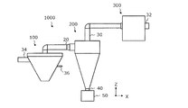
- FIG. 1 is a diagram schematically showing a configuration example of the RTB-based sintered magnet alloy crushing system 1000 according to the present embodiment.
- the present inventors have made an RTB-based sintered magnet having a reduced oxygen content, and if the powder particles are made smaller in the crushing step, the crushing efficiency is deteriorated and the crushing is performed. It was found that the powder particles deteriorated (nitrided) due to the inert gas (particularly when dry nitrogen gas was used as the inert gas) in the process, and the desired effect of improving the magnetic characteristics could not be obtained by making the crushed particles smaller. It was. As a result of further studies, the present inventors have found that the deterioration of powder particles due to the inert gas can be reduced by using the humidified inert gas.
- an actively humidified inert gas stream is used in an attempt to reduce the size of the pulverized particles.
- the oxygen content of the fine powder of Patent Document 1 is relatively high at 4500 ppm and 4900 ppm by mass ratio, and Patent Document 2 does not describe the oxygen content.
- the present inventors unexpectedly obtain the final result.
- the step of increasing the oxygen content of the RTB-based sintered magnet in the steps after crushing is mainly the step of molding and sintering fine powder to produce a sintered body.
- the increase in oxygen content of the -TB-based sintered magnet is small (for example, 50 ppm or more and 300 ppm or less in terms of mass ratio).
- the oxygen content of the RTB-based sintered magnet can be adjusted by the pulverization step. That is, in the present disclosure, powder particles are pulverized by humidifying so that the oxygen content of the obtained RTB-based sintered magnet in the pulverization step is within a specific range (1000 ppm or more and 3500 ppm or less, preferably 1000 ppm or more and 3200 ppm or less).
- the average particle size is 2.0 ⁇ m or more and 4.5 ⁇ m or less, preferably the average particle size is 2.0 ⁇ m or more and 3.5 ⁇ m or less), so that the pulverizability can be improved and the magnetism due to oxidation or sintering in the pulverization step can be improved.
- the average crystal grain size of the main phase of the R-T-B based sintered magnet R 2 T 14 B phase is at 3 ⁇ m or more 7 ⁇ m or less, and containing oxygen, carbon, nitrogen,
- the oxygen content is 1000 ppm or more and 3500 ppm or less by mass ratio
- the carbon content is 80 ppm or more and 1500 ppm or less by mass ratio
- the nitrogen content is 50 ppm or more and 600 pm or less by mass ratio
- the oxygen content is by mass ratio.
- Equation 1 [O]>[C]> [N]
- Equation 2 [O] ⁇ 1.5 ⁇ [N]
- Equation 3 [C] ⁇ 1.5 ⁇ [N]
- R is a rare earth element and always contains at least one selected from the group consisting of Nd, Pr and Ce, and T is at least one of the transition metals and always contains Fe.
- the method for manufacturing this RTB-based sintered magnet is as follows. (1) A step of preparing a coarsely pulverized powder of an alloy for RTB-based sintered magnets having an average particle size of 10 ⁇ m or more and 500 ⁇ m or less. (2) The coarsely pulverized powder is supplied to a jet mill device in which the pulverization chamber is filled with an inert gas to pulverize the coarsely pulverized powder to obtain a fine powder having an average particle size of 2.0 ⁇ m or more and 4.5 ⁇ m or less. Process and (3) A step of producing the fine powder sintered body and The inert gas is humidified. The average particle size (d50) can be measured by airflow dispersion laser diffraction.
- the RTB-based sintered magnet of the present disclosure has an oxygen content of 1000 ppm or more and 3500 ppm or less in terms of mass ratio.
- the oxygen content is set to 1000 ppm or more and 3500 ppm or less, in the step of obtaining the fine powder of (2) above, the humidification of the inert gas is too weak, and the deterioration (oxidation) of the powder particles due to the inert gas progresses. It is possible to suppress the deterioration of the magnetic characteristics due to the deterioration of the magnetic characteristics due to the above and the oxidation of the powder particles due to the humidification.
- the oxygen content of the RTB-based sintered magnet is preferably 1000 ppm or more and 3200 ppm or less, more preferably 1000 ppm or more and 2400 ppm or less, and further preferably 1300 ppm or more and 2400 ppm or less.
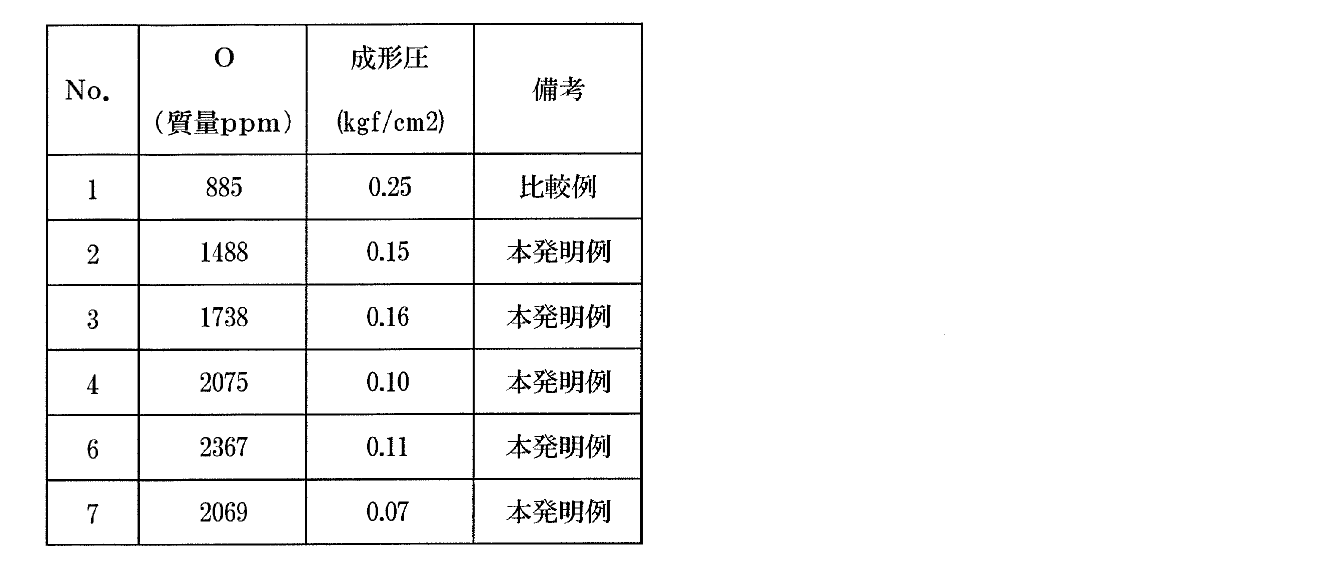
- the compressibility in molding is improved as shown in Examples described later. be able to. By improving the compressibility, molding can be performed at a lower molding pressure. This makes it possible to suppress the occurrence of cracks in the molded product.
- the continuous moldability can be improved by reducing the load on the mold and the frequency of mold repair can be reduced, so that the production efficiency can be improved.
- the oxygen content of the RTB-based sintered magnet is 2000 ppm or more.
- the moldability can be further improved. Therefore, the oxygen content of the R-T-B based sintered magnet Considering the formability and magnetic properties (B r and H cJ) is preferably 2000ppm or 2400ppm or less.
- composition of the preferred RTB-based sintered magnet is shown below.
- R is a rare earth element and always contains at least one selected from the group consisting of Nd, Pr and Ce.
- R is a rare earth element and always contains at least one selected from the group consisting of Nd, Pr and Ce.
- a combination of rare earth elements represented by Nd-Dy, Nd-Tb, Nd-Dy-Tb, Nd-Pr-Dy, Nd-Pr-Tb, and Nd-Pr-Dy-Tb is used.
- Dy and Tb are particularly effective in improving HcJ.
- other rare earth elements such as La may be contained, and mischmetal or didymium may be used.
- R does not have to be a pure element, and may contain impurities unavoidable in production within the range industrially available.
- the content is, for example, 27% by mass or more and 35% by mass or less.
- the R content of the RTB-based sintered magnet is 31% by mass or less (27% by mass or more and 31% by mass or less, preferably 29% by mass or more and 31% by mass or less).
- the R content of the RTB-based sintered magnet By setting the R content of the RTB-based sintered magnet to 31% by mass or less and the oxygen content to be 1000 ppm or more and 3500 ppm or less in terms of mass ratio, the R oxidized by humidification during humidification and pulverization Occurrence is reduced. Therefore, higher magnetic characteristics can be obtained.
- T contains iron (including the case where T is substantially composed of iron), and 50% or less of the mass ratio may be replaced with cobalt (Co) (T is substantially composed of iron and cobalt). Including the case). Co is effective for improving temperature characteristics and corrosion resistance, and the alloy powder may contain 10% by mass or less of Co.
- the content of T may occupy the balance of R and B or R and B and M described later.
- the content of B may be a known content, and for example, 0.9% by mass to 1.2% by mass is a preferable range. Is less than 0.9 wt% may high H cJ can not be obtained in some cases to lower the B r exceeds 1.2 mass%.
- a part of B can be replaced with C (carbon). More preferably, it is 1.0% by mass or less, and further preferably 0.96% by mass or less.
- M element can be added to improve H cJ.
- the M element is one or more selected from the group consisting of Al, Si, Ti, V, Cr, Mn, Ni, Cu, Zn, Ga, Zr, Nb, Mo, In, Sn, Hf, Ta and W. ..
- the amount of M element added is preferably 5.0% by mass or less. This is because Br may decrease if it exceeds 5.0% by mass. Inevitable impurities can also be tolerated.
- the content of N (nitrogen) in the RTB-based sintered magnet is preferably 50 ppm or more and 600 ppm or less in terms of mass ratio.
- the nitrogen content is more preferably 50 ppm or more and 400 ppm or less, and most preferably 100 ppm or more and 300 ppm or less. This is because it is possible to suppress a decrease in magnetic properties due to nitriding while further improving grindability.
- the C (carbon) content in the RTB-based sintered magnet) is preferably 80 ppm or more and 1500 ppm or less, and more preferably 80 ppm or more and 1000 ppm or less in terms of mass ratio. Further, the lower limit of the C content can be 500 ppm, or 800 ppm or more. Further, in the RTB-based sintered magnet of the present disclosure, when the oxygen content is [O], the carbon content is [C], and the nitrogen content is [N] in terms of mass ratio, the following It is preferable that the formulas 1 to 3 of the above are satisfied. Equation 1: [O]>[C]> [N], Equation 2: [O] ⁇ 1.5 ⁇ [N], Equation 3: [C] ⁇ 1.5 ⁇ [N]
- the amount of oxygen increases by performing humidification pulverization as described above, but nitriding due to pulverization is particularly suppressed.
- the contents of oxygen, carbon, and nitrogen in the obtained RTB-based sintered magnet can be as shown in Equation 1 ([O]> [C]> [N]).
- the nitrogen content is smaller than the oxygen and carbon contents, and formulas 2 ([O] ⁇ 1.5 ⁇ [N]) and formula 3 ([C]). ⁇ 1.5 ⁇ [N]).
- [O] ⁇ 3 ⁇ [N] is more preferable, [O] ⁇ 5 ⁇ [N] is more preferable, and [O] ⁇ 10 ⁇ [N] is the most preferable.
- [C] ⁇ 2 ⁇ [N] is more preferable, and [C] ⁇ 5 ⁇ [N] is most preferable.
- the average crystal grain size of the R 2 T 14 B phase as a main phase of the R-T-B based sintered magnet of the present disclosure is 3.5 ⁇ m or more 7.0 ⁇ m or less.
- the average crystal grain size can be determined by averaging the number of crystal grains (5,000 or more) having a circle-equivalent diameter evaluated by EBSD (Electron Backscatter Diffraction).
- the step of preparing the coarsely pulverized powder of the alloy for RTB-based sintered magnet having an average particle size of 10 ⁇ m or more and 500 ⁇ m or less includes the step of preparing the alloy for RTB-based sintered magnet and, for example, this alloy. It includes a step of coarsely crushing by a hydrogen crushing method or the like.
- An alloy ingot can be obtained by an ingot casting method in which a metal or alloy prepared in advance so as to have the above-mentioned composition is melted and placed in a mold. Further, it is represented by a strip casting method or a centrifugal casting method in which a molten metal is brought into contact with a single roll, a double roll, a rotating disk, a rotating cylindrical mold, or the like and rapidly cooled to produce a solidified alloy thinner than the alloy produced by the ingot method. Alloy flakes can be produced by the quenching method.
- a material produced by either an ingot method or a quenching method can be used, but it is preferably produced by a quenching method such as a strip cast method.
- the thickness of the quenching alloy produced by the quenching method is usually in the range of 0.03 mm to 1 mm and has a flake shape.
- the molten alloy begins to solidify from the contact surface of the cooling roll (roll contact surface), and crystals grow in columns from the roll contact surface in the thickness direction. Since the quenching alloy is cooled in a short time as compared with the alloy (ingot alloy) produced by the conventional ingot casting method (mold casting method), the structure is made finer and the crystal grain size is smaller. Also, the area of grain boundaries is large.
- the quenching method is excellent in the dispersibility of the R-rich phase. Therefore, it is easily broken at the grain boundaries by the hydrogen pulverization method.
- the size of the hydrogen pulverized powder (coarse pulverized powder) can be reduced to, for example, 1.0 mm or less.
- the coarsely pulverized powder thus obtained is pulverized by a jet mill in a humidified atmosphere (step (2)).
- FIG. 1 is a diagram schematically showing a configuration example of the crushing system 1000 according to the present embodiment.
- the RTB-based sintered magnet alloy crushing system 1000 includes a jet mill device 100, a cyclone collecting device 200, and a bag filter device 300.
- the jet mill device 100 receives a supply of a material to be crushed from a raw material tank (not shown) via a raw material input pipe 34.
- the object to be pulverized is a coarsely pulverized powder of an alloy for RTB-based sintered magnets having an average particle size of 10 ⁇ m or more and 500 ⁇ m or less.
- the average particle size (d50) in the present disclosure can be measured by an airflow dispersion type laser diffraction method (based on JIS Z 8825: 2013 revised edition). That is, in the present specification, the average particle size means a particle size (median diameter) at which the integrated particle size distribution (volume basis) from the small particle size side is 50%.
- the average particle size (d50) in the embodiment of the present disclosure is d50 measured under the conditions of dispersion pressure: 4 bar, measurement range: R2, and calculation mode: HRLD, using a particle size distribution measuring device "HELOS & RODOS" manufactured by Symboltec. Indicates that.
- a plurality of valves are provided in the raw material input pipe 34, and the internal pressure of the jet mill device 100 is appropriately maintained by opening and closing the valves.
- the object to be crushed introduced inside the jet mill device 100 is a collision plate installed to efficiently promote mutual collision and pulverization between the objects to be crushed by high-speed injection of an inert gas from the nozzle tube 36. It is finely crushed by the collision of.
- a humidifying tube for including water in the inert gas is connected to the nozzle tube 36.
- the powder of the RTB-based sintered magnet alloy is active and easily oxidized. Therefore, the gas used in the jet mill device 100 generally has a dew point in order to avoid the risk of heat generation and ignition and reduce the oxygen content as an impurity to improve the performance of the magnet.
- a dry (high-purity), inert gas such as nitrogen, argon, or helium at -60 ° C or lower is used.
- pulverization is performed in a humidified state in which water is intentionally introduced into such an inert gas. Details of this point will be described later.
- the powder particles (fine powder) pulverized inside the jet mill device 100 are guided by the updraft from the upper discharge port 40 to the inlet pipe 20 of the cyclone collection device 200.
- Coarse particles with insufficient crushing are sorted by a classification rotor installed to classify coarse particles having a medium diameter (d50) or more, remain inside the jet mill device 100, and are further subjected to a crushing process by collision. It will be.
- a classification rotor may be used, or centrifugation by a swirling flow may be used.
- the object to be pulverized (coarse pulverized powder) charged into the jet mill device 100 is pulverized into fine powder having an average particle size (medium diameter: d50) of 2.0 ⁇ m or more and 4.5 ⁇ m or less. It will move to the cyclone collection device 200.
- the cyclone collector 200 is used to separate the powder from the airflow that carries the powder. Specifically, the coarsely pulverized powder of the RTB-based sintered magnet alloy is pulverized by the jet mill in the previous stage, and the fine powder produced by the pulverization passes through the inlet pipe 20 together with the gas used for the pulverization. Is supplied to the cyclone collecting device 200. A mixture of an inert gas (crushed gas) and crushed fine powder forms a high-speed air flow and is sent to the cyclone collecting device 200. The cyclone collecting device 200 is used to separate these pulverized gases and fine powders. The fine powder separated from the crushed residue is collected by the powder collector 50 via the discharge port 40.
- the crushed gas is supplied to the bag filter device 300 via the outlet pipe 30.
- the bag filter device 300 very small fine particles are collected, and clean gas is discharged to the outside from the exhaust port 32.
- the air scattering of fine powder due to the breakage of the filter gives environmental and safety aspects. A large impact. Fine particles may be further separated from the gas after being separated by the cyclone collecting device 200 by using a bag filter in combination.
- the characteristic point of the present disclosure is that humidification and pulverization are performed so that the oxygen content of the RTB-based sintered magnet is in the range of 1000 ppm or more and 3500 ppm or less in terms of mass ratio.
- both deterioration (nitriding) of powder particles due to crushing and oxidation due to humidification can be suppressed, and high magnetic properties can be obtained.
- the increase in oxygen content of the RTB-based sintered magnet is usually small (for example, 50 ppm or more and 300 ppm) due to the steps after pulverization (mainly the step of producing the fine powder sintered body). Less than). Therefore, it is possible to adjust the oxygen content of the RTB-based sintered magnet by the pulverization step.
- the humidified inert gas in the step (2) can be obtained, for example, by giving the inert gas 0.5 g or more and 6.0 g or less of water per 1 kg of the coarsely pulverized powder. If it is less than 0.5 g, deterioration (nitriding) of the powder particles due to pulverization cannot be suppressed, and the magnetic properties may deteriorate. On the other hand, if it exceeds 6.0 g, the humidification is too strong, so that the powder particles may be oxidized and the magnetic properties may be deteriorated.
- the dew point in the crushing chamber and the amount of coarsely pulverized powder supplied to the jet mill device also depend on the crushing time and the size of the jet mill device, but in a preferred embodiment, the inert gas has a dew point at the time of crushing. It is humidified so that the temperature is -55 ° C or higher and -30 ° C or lower. In a further preferred embodiment, the rate at which the coarsely milled powder is supplied to the jet mill device is 35 kg / hour or more and 180 kg / hour or less.
- inert gases examples include nitrogen, argon and helium. Of these, nitrogen is most preferable because a high-purity gas can be obtained at low cost. Therefore, in a preferred embodiment, the inert gas is nitrogen gas.
- the inert gas is nitrogen gas.
- the average particle size of the obtained fine powder becomes 4.5 ⁇ m or less, magnetism is achieved by nitriding. It was found that the properties began to decline. In particular, it was found that when the average particle size is 3.5 ⁇ m or less, the magnetic characteristics may be significantly deteriorated due to nitriding.
- the inert gas in the pulverization chamber is mainly nitrogen
- the active surface of the particles revealed by pulverization is nitrided by humidifying the particles so that they contain a specific adjusted amount of water. It is thought that this is because it can be thinly oxidized first.
- the increase in oxygen content of the RTB-based sintered magnet by the steps after the fine pulverization is 50 ppm or more and 300 ppm or less in terms of mass ratio.
- the average particle size of the fine powder in the step of obtaining the fine powder is 2.0 ⁇ m or more and 4.5 ⁇ m or less. If it is less than 2.0 ⁇ m, the pulverization particle size of the fine powder may be too small to suppress the deterioration of pulverization efficiency during jet mill pulverization, and if it exceeds 4.5 ⁇ m, high magnetic properties may not be obtained. is there.
- the pulverized particle size of the fine powder is more preferably 2.0 ⁇ m or more and 3.5 m or less. By reducing the average particle size, it becomes possible to improve the magnet characteristics.
- the step of producing a fine powder sintered body includes a step of producing a powder molded body from the fine powder by pressing in a magnetic field and a step of sintering the powder molded body.
- the magnetic field press it is preferable to form the powder compact by pressing in an inert gas atmosphere or wet pressing from the viewpoint of suppressing oxidation.
- the surface of the particles constituting the powder molded product is coated with a dispersant such as an oil agent, and contact with oxygen and water vapor in the atmosphere is suppressed. Therefore, it is possible to prevent or suppress the particles from being oxidized by the atmosphere before and after the pressing process or during the pressing process.
- the dispersion medium is a liquid from which a slurry can be obtained by dispersing alloy powder in the dispersion medium.
- Mineral oil or synthetic oil can be mentioned as a preferable dispersion medium used in the present disclosure.
- the type of mineral oil or synthetic oil is not specified, but when the kinematic viscosity at room temperature exceeds 10 cSt, the bonding force between the alloy powders increases due to the increase in viscosity, and the orientation of the alloy powders during wet molding in a magnetic field. May have an adverse effect on. Therefore, the kinematic viscosity of mineral oil or synthetic oil at room temperature is preferably 10 cSt or less.
- the fractional distillation point of mineral oil or synthetic oil is preferably 400 ° C. or lower.
- vegetable oil refers to oil extracted from plants, and the type of plant is not limited to a specific plant.
- a slurry can be obtained by mixing the obtained alloy powder and a dispersion medium.
- the mixing ratio of the alloy powder and the dispersion medium is not particularly limited, but the concentration of the alloy powder in the slurry is preferably 70% or more (that is, 70% by mass or more) in terms of mass ratio. This is because the alloy powder can be efficiently supplied to the inside of the cavity at a flow rate of 20 to 600 cm 3 / sec, and excellent magnetic properties can be obtained.
- the concentration of the alloy powder in the slurry is preferably 90% or less in terms of mass ratio.
- the method of mixing the alloy powder and the dispersion medium is not particularly limited. The alloy powder and the dispersion medium may be prepared separately, weighed in a predetermined amount, and mixed to produce the mixture.
- the coarsely pulverized powder is dry-pulverized with a jet mill or the like to obtain an alloy powder
- a container containing a dispersion medium is placed in the alloy powder discharge port of a pulverizer such as a jet mill, and the alloy powder is pulverized. May be directly recovered in the dispersion medium in the container to obtain a slurry.
- the inside of the container also has an atmosphere composed of nitrogen gas and / or argon gas, and the obtained alloy powder is directly recovered in the dispersion medium without being exposed to the atmosphere to form a slurry.
- a slurry composed of the alloy powder and the dispersion medium by wet pulverization using a vibration mill, a ball mill, an attritor or the like while holding the coarsely pulverized powder in the dispersion medium.
- a molded product having a predetermined size and shape can be obtained.
- This molded product is sintered to obtain a sintered body.
- the molded body is sintered to obtain a rare earth sintered magnet body (sintered body).
- Sintering of the molded product is preferably performed under a pressure of 0.13 Pa (10 -3 Torr) or less, more preferably 0.07 Pa (5.0 ⁇ 10 -4 Torr) or less, at a temperature of 1000 ° C. to 1150 ° C. Do it in the range.
- the residual gas in the atmosphere can be replaced by an inert gas such as helium or argon. It is preferable to heat-treat the obtained sintered body.
- the magnetic properties can be improved by heat treatment. Known conditions can be adopted as the heat treatment conditions such as the heat treatment temperature and the heat treatment time.
- the rare earth sintered magnet body thus obtained is subjected to a grinding / polishing step, a surface treatment step, and a magnetizing step as necessary to complete a final rare earth sintered magnet.
- the method for producing an RTB-based sintered magnet of the present disclosure is to introduce a heavy rare earth element RH (RH is at least one of Tb, Dy, and Ho) from the surface of the sintered body to the inside. It further includes a diffusion step of diffusion. By diffusing the heavy rare earth element RH from the surface of the sintered body to the inside, the coercive force can be efficiently increased. As shown in Examples described later, when the diffusion step is performed on the sintered body subjected to the humidification crushing of the present disclosure, the HcJ is higher than that in the case where the diffusion step is performed on the sintered body not subjected to the humidification crushing. It turned out to be obtained.
- the method of the diffusion step is not particularly limited. A known method can be adopted.
- the RTB-based sintered magnet in which these are diffused includes a portion in which at least one of the Tb concentration and the Dy concentration gradually decreases from the magnet surface toward the inside of the magnet. That is, the fact that the RTB-based sintered magnet includes a portion where at least one of the Tb concentration and the Dy concentration gradually decreases from the surface of the magnet to the inside of the magnet means that at least one of Tb and D diffuses from the surface of the magnet to the inside of the magnet. It means that it is in a state of being sintered.
- the concentration of Tb and Dy when the size of the measurement site is, for example, submicron, the measurement site may vary depending located either main phase crystal grains (R 2 T 14 B compound particles) and grain boundary. Further, when the measurement site is located at the grain boundary, the concentration of Tb or Dy may change locally or microscopically depending on the type and distribution of the compound containing Tb or Dy that can be formed at the grain boundary. .. However, when Tb and Dy are diffused from the magnet surface to the inside of the magnet, the average concentration values of these elements at positions having the same depth from the magnet surface gradually decrease from the magnet surface toward the inside of the magnet. It is clear that we will go.
- At least one of the average concentrations of Tb and Dy measured as a function using the depth as a parameter is the depth in a region from the magnet surface of the RTB-based sintered magnet to a depth of 200 ⁇ m. If it decreases with increasing, the RTB-based sintered magnet is defined to include a portion where at least one of the Tb concentration and the Dy concentration gradually decreases.
- the R content of the RTB-based sintered magnet finally obtained after performing the diffusion step of diffusing the heavy rare earth element RH from the surface of the sintered body to the inside is 32% by mass or less (27% by mass or more). 32% by mass or less) is preferable.
- the R content of the RTB-based sintered magnet is 32% by mass or less, and the oxygen content is 1000 ppm or more and 3500 ppm or less (preferably 1000 ppm or more and 3200 ppm or less, more preferably 1000 ppm or more and 2400 ppm or less, and further. Higher magnetic properties can be obtained by preferably setting the value to 2000 ppm or more and 2400 ppm or less).
- the content of N (nitrogen) in the RTB-based sintered magnet finally obtained after the diffusion step is preferably 50 ppm or more and 600 ppm or less, more preferably 50 ppm or more and 400 ppm or less in terms of mass ratio, and most preferably. Preferably, it is 100 ppm or more and 300 ppm or less.
- the C (carbon) content in the RTB-based sintered magnet is preferably 80 ppm or more and 1500 ppm or less, and more preferably 80 ppm or more and 1000 ppm or less in terms of mass ratio.
- the acid oxygen content of the RTB-based sintered magnet finally obtained after the diffusion step is [O]
- the carbon content is [C]
- the nitrogen content is [N].
- Equation 1 [O]>[C]> [N]
- Equation 3 [C] ⁇ 1.5 ⁇ [N]
- the present inventors have found that the grain boundary phase in the RTB-based sintered magnet is It was found that the rare earth oxide phase had a rare earth oxide phase, and the rare earth oxide phase had a rare earth oxynitride phase. Then, when the rare earth oxynitride phase has a specific crystal structure and the contents (atomic%) of oxygen ⁇ O ⁇ and nitrogen ⁇ N ⁇ satisfy a specific relationship, high magnetic properties can be obtained. I found that I could do it.
- the effect is particularly remarkable when the diffusion step of diffusing the heavy rare earth element RH from the surface of the sintered body to the inside is performed (the effect of improving HcJ by diffusion is high).
- a structure can be preferably obtained by the humidified pulverization of the present disclosure, but is not necessarily limited to this.
- the RTB-based sintered magnet described below can be obtained by adjusting the amount of oxygen or nitrogen introduced during jet mill pulverization.
- R-T-B based sintered magnet of the present disclosure includes a main phase consisting of R 2 T 14 B compound, the R-T-B based sintered including a grain boundary phase located in the grain boundary of the main phase It is a magnet (R is a rare earth element and always contains at least one selected from the group consisting of Nd, Pr and Ce, and T is at least one of transition metals and always contains Fe).
- the average crystal grain size of the R 2 T 14 B phase, which is the main phase of the TB-based sintered magnet is 3 ⁇ m or more and 7 ⁇ m or less, and the RTB-based sintered magnet contains oxygen, carbon, and nitrogen.
- the content of oxygen is 1000 ppm or more and 3500 ppm or less by mass ratio
- the content of nitrogen is 50 ppm or more and 600 pm or less by mass ratio
- the grain boundary phase has a rare earth oxide phase and the rare earth oxidation.
- the physical phase includes a rare earth oxynitride phase having a NaCl-type crystal structure
- the content of O in the rare earth oxynitride phase (atomic%) is ⁇ O ⁇
- the content of N in the rare earth oxynitride phase (Atomic%) When ⁇ N ⁇ is used as the atomic%), the relationship of ⁇ O ⁇ > 1.8 ⁇ ⁇ N ⁇ is satisfied.
- the RTB-based sintered magnet has a C content (atomic%) in the rare earth oxynitride phase of ⁇ C ⁇ > ⁇ N ⁇ ⁇ 0.5, where ⁇ C ⁇ is used. Further satisfy the relationship.
- the ratio of the area of the rare earth oxynitride phase to the area of the rare earth oxide phase is preferably 50% or more.
- the average crystal grain size of the R 2 T 14 B phase which is the main phase of the RTB system sintered magnet, is 3 ⁇ m or more and 7 ⁇ m or less (preferably 3 ⁇ m or more and 5 ⁇ m or less).
- the sinter magnet contains oxygen, carbon, and nitrogen, and the oxygen content is 1000 ppm or more and 3500 ppm or less (preferably 1000 ppm or more and 2500 ppm or less) by mass ratio, and the nitrogen content is 50 ppm or more and 600 pm or less by mass ratio. .. As a result, high magnetic properties can be obtained.
- the grain boundary phase in the RTB-based sintered magnet has a rare earth oxide phase, and the rare earth oxide phase contains a rare earth oxynitride phase having a NaCl-type crystal structure.
- the present inventors have found that the rare earth oxynitride phase having a NaCl-type crystal structure is easily bound to carbon (C). Therefore, it was found that by having a rare earth oxynitride phase having a NaCl-type crystal structure, the amount of C in the main phase can be reduced, and as a result, high magnetic properties can be obtained.
- the rare earth oxynitride phase having a NaCl-type crystal structure does not easily form an oxide with a heavy rare earth element (for example, Tb or Dy). Therefore, when the RTB-based sintered magnet contains Tb or Dy, the Rare earth oxynitride phase having a NaCl-type crystal structure is provided at the grain boundary so that the main phase contains Tb or Dy. And high magnetic properties can be obtained. As shown in Examples described later, the effect is particularly remarkable when the diffusion step of diffusing the heavy rare earth element RH from the surface of the sintered body to the inside is performed.
- a heavy rare earth element for example, Tb or Dy
- the rare earth oxynitride phase has an O content (atomic%) in the rare earth oxynitride phase as ⁇ O ⁇ and an N content (atom%) in the rare earth oxynitride phase as ⁇ N ⁇ .
- O content atomic% in the rare earth oxynitride phase
- N content atom% in the rare earth oxynitride phase
- the O and N contents of the rare earth oxynitride phase having a NaCl-type crystal structure at the grain boundary are ⁇ O ⁇ > 1.8 ⁇ .
- the formation of nitrides with heavy rare earth elements can be suppressed, and Tb and Dy can be contained in the main phase, so that high magnetic properties can be obtained.
- the effect is particularly remarkable when the diffusion step of diffusing the heavy rare earth element RH from the surface of the sintered body to the inside is performed.
- the content (atomic%) of C in the rare earth oxynitride phase is ⁇ C ⁇
- the relationship of ⁇ C ⁇ > ⁇ N ⁇ ⁇ 0.5 is satisfied, and the C of the main phase is satisfied.
- the amount can be reduced and higher magnetic properties can be obtained.
- the ratio of the area of the rare earth oxynitride phase to the area of the rare earth oxide phase is preferably 50% or more.
- the ratio of the area of the rare earth oxynitride phase to the area of the rare earth oxide phase is 70% or more, more preferably 90% or more.
- the grain boundary phase in the RTB-based sintered magnet has a rare earth oxide phase and the rare earth oxide phase contains a rare earth oxynitride phase having a NaCl type crystal structure
- the grain boundary phase in the RTB-based sintered magnet has a rare earth oxide phase and the rare earth oxide phase contains a rare earth oxynitride phase having a NaCl type crystal structure
- the rare earth oxynitride phase has an O content (atomic%) in the rare earth oxynitride phase as ⁇ O ⁇ and an N content (atom%) ⁇ N ⁇ in the rare earth oxynitride phase.
- ⁇ O ⁇ > 1.8 ⁇ ⁇ N ⁇ is satisfied, for example, by EDX (energy dispersive X-ray analysis) or WDX (wavelength dispersive X-ray analysis). Alternatively, it can be confirmed by performing surface analysis.
- the ratio of the area of the rare earth oxynitride phase to the area of the rare earth oxide phase is 50% or more is determined, for example, by mapping EDX or WDX in a certain field of view and using commercially available software to determine the rare earth oxide. It can be confirmed by color-coding the phases, further color-coding the rare earth oxynitride phase in the phase, and counting the number of pixels of the color of each phase.
- Example 1 Approximately the sample No. of Table 1 Alloys for RTB-based sintered magnets were prepared by a strip casting method (excluding O, C, and N) so as to have the compositions of RTB-based sintered magnets shown in 1 to 13. Each of the obtained alloys was coarsely pulverized by a hydrogen pulverization method to obtain a coarsely pulverized powder. The average particle size of the coarsely ground powder was measured. The average particle size was in the range of 200 ⁇ m to 400 ⁇ m. In the present disclosure, the average particle size means a particle size (median diameter) at which the integrated particle size distribution (volume basis) from the small particle size side is 50%. The average particle size (d50) was measured with a particle size distribution measuring device "HELOS &RODOS" manufactured by Symbolec under the conditions of dispersion pressure: 4 bar, measurement range: R2, and calculation mode: HRLD.
- HELOS &RODOS particle size distribution measuring device manufactured by Symbolec under the conditions of dispersion pressure:
- the coarsely pulverized powder was put into the jet mill device 100 of FIG. 1 and the coarsely pulverized powder was pulverized to obtain a fine powder.
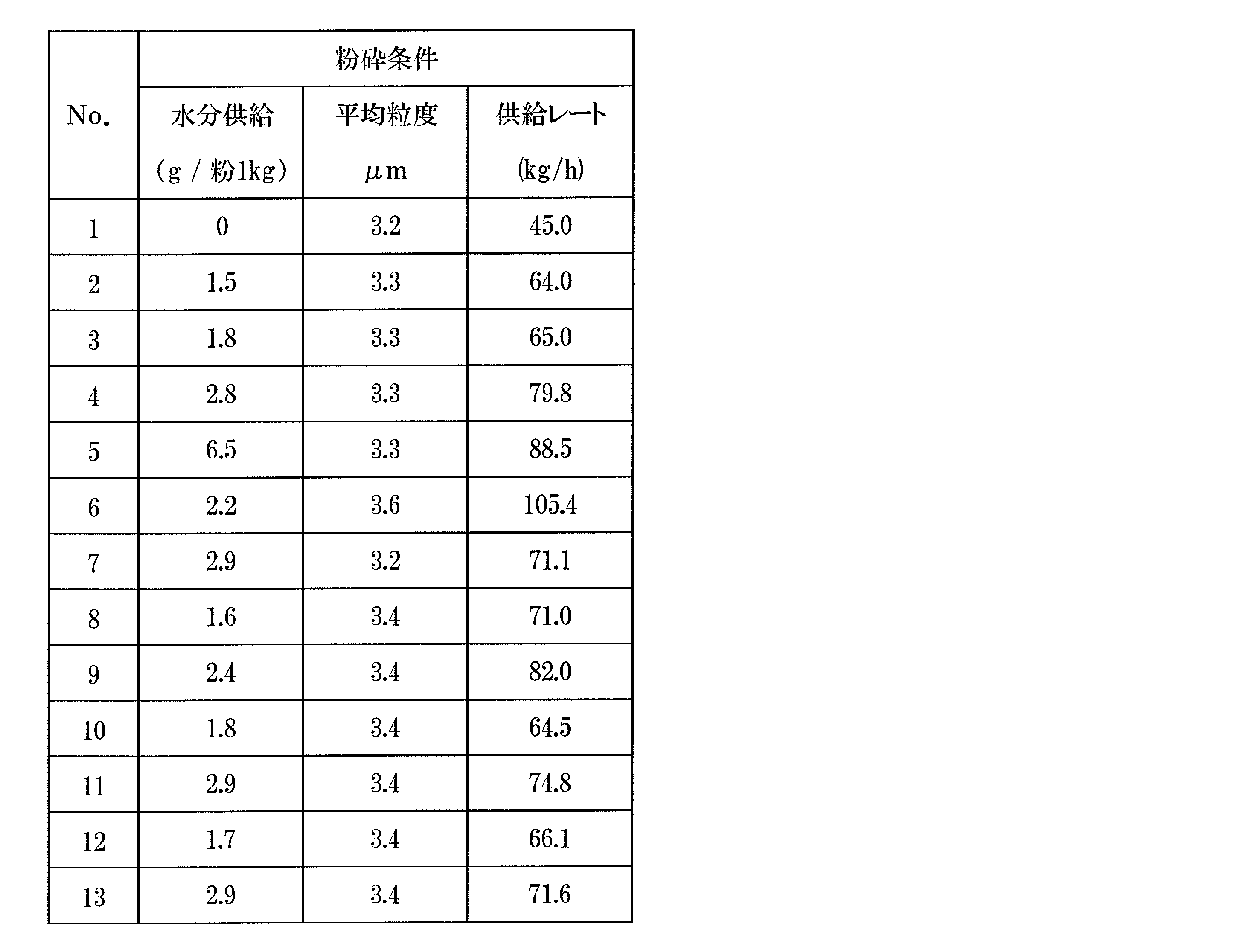
- the crushing conditions are shown in Table 2. No. in Table 2 No. 2 is obtained by giving 1.5 g of water per 1 kg of the coarsely pulverized powder to an inert gas and pulverizing by humidification, and the amount of the coarsely pulverized powder supplied to the jet mill device is 64.0 kg / h. No. 1 and No. 3 to 13 are also described in the same manner (No. 1 is crushed without humidification). In this example, nitrogen gas was used as the inert gas. Table 2 shows the average particle size of the obtained fine powder.
- the fine powder was immersed in a mineral oil having a fractional distillation point of 250 ° C. and a kinematic viscosity of 2 cSt at room temperature in a nitrogen atmosphere to prepare a slurry.
- the slurry concentration was 85% by mass.
- the obtained slurry was molded (wet molded) in a magnetic field to obtain a molded product.
- a so-called right-angled magnetic field forming apparatus transverse magnetic field forming apparatus in which the magnetic field application direction and the pressurizing direction are orthogonal to each other was used.
- the obtained molded product was sintered in vacuum at 1040 ° C.
- the sintered body is subjected to a heat treatment of holding at 800 ° C. for 2 hours and then cooling to room temperature, then holding at 500 ° C. for 2 hours and then cooling to room temperature to obtain a sintered body (RTB-based sintered magnet). ) was obtained.
- the components of the obtained sintered magnet were determined. The contents of Nd, Pr, B, Co, Al, Cu, Ga and Zr were measured by ICP emission spectroscopy.
- O oxygen amount
- N nitrogen amount
- C carbon amount
- No. Nos. 1 to 5 have substantially the same composition except for C, O, and N, and the average particle size of the fine powder obtained by jet mill pulverization is also substantially the same.
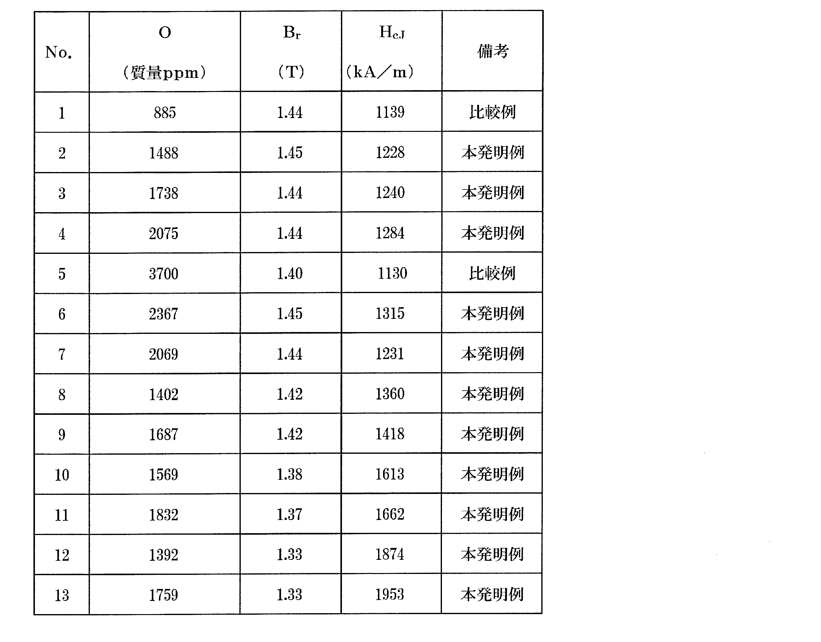
- Table 3 none of the examples of the present invention (Nos. 2 to 4) were humidified and pulverized. Higher magnetic characteristics than No. 1 are obtained. Conventionally, it has been considered that the magnetic properties decrease as the amount of oxygen increases if the composition and particle size are almost the same. However, No. 1 and No. As shown in 2 to 4, if the oxygen content of the RTB -based sintered magnet of the present disclosure is within the range, the magnetic characteristics are improved (H cJ is improved).
- the oxygen content of the RTB-based sintered magnet of the present disclosure is out of the range, No. As shown in 5, the magnetic characteristics are deteriorated. Further, as shown in Table 2, when pulverizing to an average particle size of about 3.3 ⁇ m, the supply rate of the example of the present invention can be increased as compared with the non-humidified comparative example (No. 1). That is, the crushability is good. Further, from the results in Tables 2 and 3, it can be seen that the oxygen content of the RTB-based sintered magnet is preferably 1700 ppm or more in order to obtain higher grindability. Further, as shown in Table 3, all of the examples of the present invention have obtained high magnetic properties of Br ⁇ 1.33T and H cJ ⁇ 1200 kA / m.
- Example 1 No. 1 to 3 sintered bodies were prepared.
- the sintered body was subjected to a diffusion step of diffusing the heavy rare earth element RH from the surface of the sintered body to the inside.
- the raw materials of each element were weighed so as to have a composition of Pr80Tb10Ga7Cu3 in terms of mass ratio, and the raw materials were dissolved to obtain a ribbon or flake-shaped alloy by a single roll ultra-quenching method (melt spinning method). ..
- the obtained alloy was pulverized in an argon atmosphere and then passed through a sieve having a mesh size of 425 ⁇ m to prepare a diffusion alloy powder.
- the sintered bodies 1 to 3 were cut and ground to obtain a cube having a size of 7.2 mm ⁇ 7.2 mm ⁇ 7.2 mm.
- No. The diffusion alloy was sprayed on the entire surface of the sintered bodies 1 to 3 in an amount of 2.5% by mass based on 100% by mass of the RTB-based sintered magnet. Then, it is heat-treated at a temperature of 900 ° C. for 10 hours in vacuum argon controlled to 50 Pa, then cooled to room temperature, and further heat-treated at 500 ° C. for 3 hours in vacuum argon controlled to 50 Pa to diffuse. Later RTB-based sintered magnets (No. 20-23) were produced.
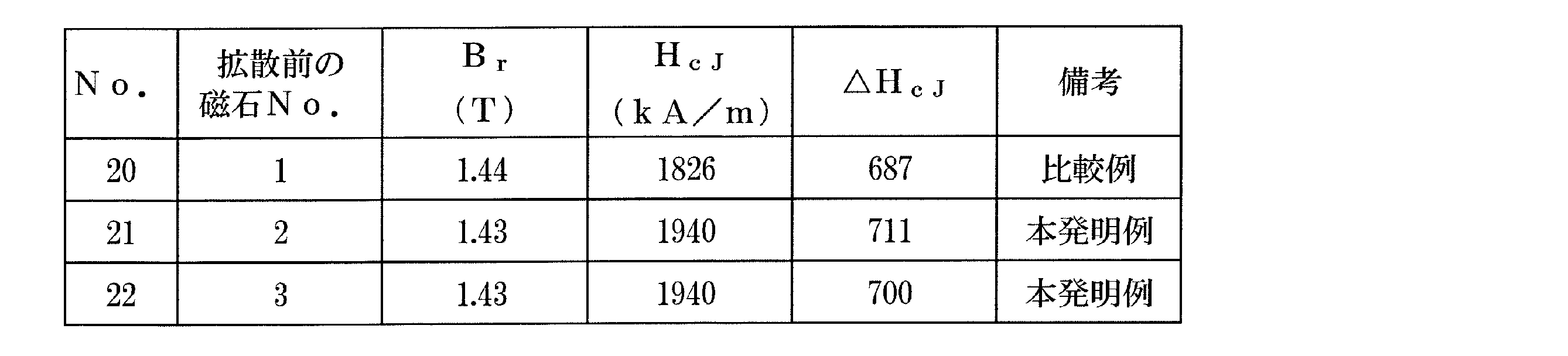
- the examples of the present invention (No. 21 and No. 22) in which the diffusion step was performed on the sintered body subjected to the humidified pulverization of the present disclosure diffused into the sintered body not subjected to the humidified pulverization.
- a higher ⁇ H cJ was obtained as compared with the comparative example (No. 20) in which the step was performed.
- the oxygen content of the R-T-B based sintered magnet is preferably at least 2000ppm by mass ratio, the magnetic properties shown in Table 3 (B r and H cJ) also considering the R-T-B based sintered magnet oxygen
- the content is preferably 2000 ppm or more and 2400 ppm or less in terms of mass ratio.
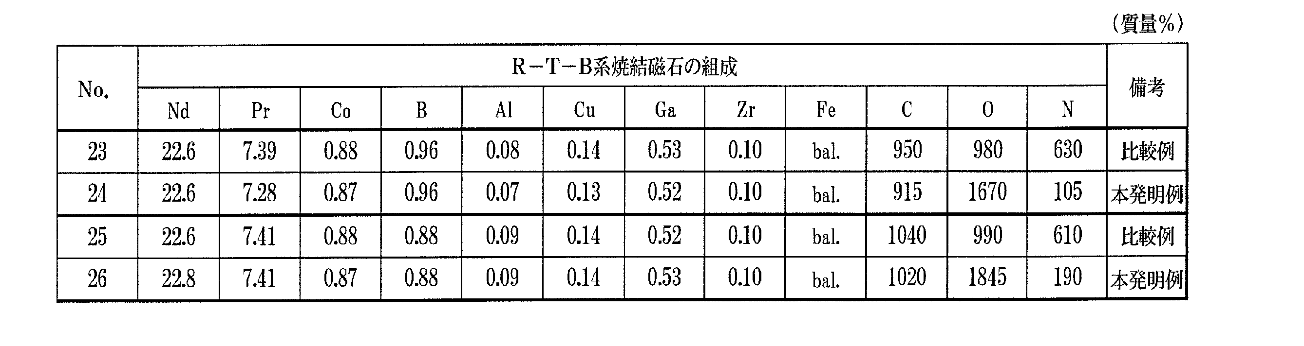
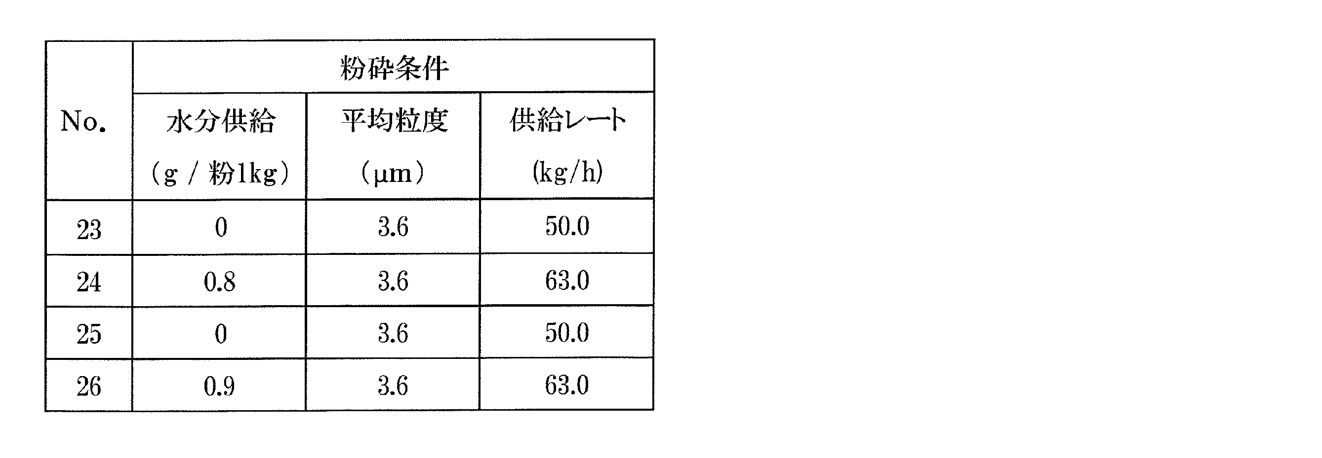
- Example 3 In the same manner as in Example 1, alloys for RTB-based sintered magnets were prepared so as to have the composition of RTB-based sintered magnets shown in Sample Nos. 23 to 26 in Table 6. The obtained RTB-based sintered magnet alloy was coarsely pulverized in the same manner as in Example 1 to obtain a coarse pulverized powder. The obtained crude pulverized powder was pulverized in the same manner as in Example 1 to obtain a fine powder. The crushing conditions are shown in Table 7. The obtained fine pulverization was subjected to molding, sintering, and heat treatment in the same manner as in Example 1 to obtain an RTB-based sintered magnet. The components of the obtained sintered magnet were determined in the same manner as in Example 1.
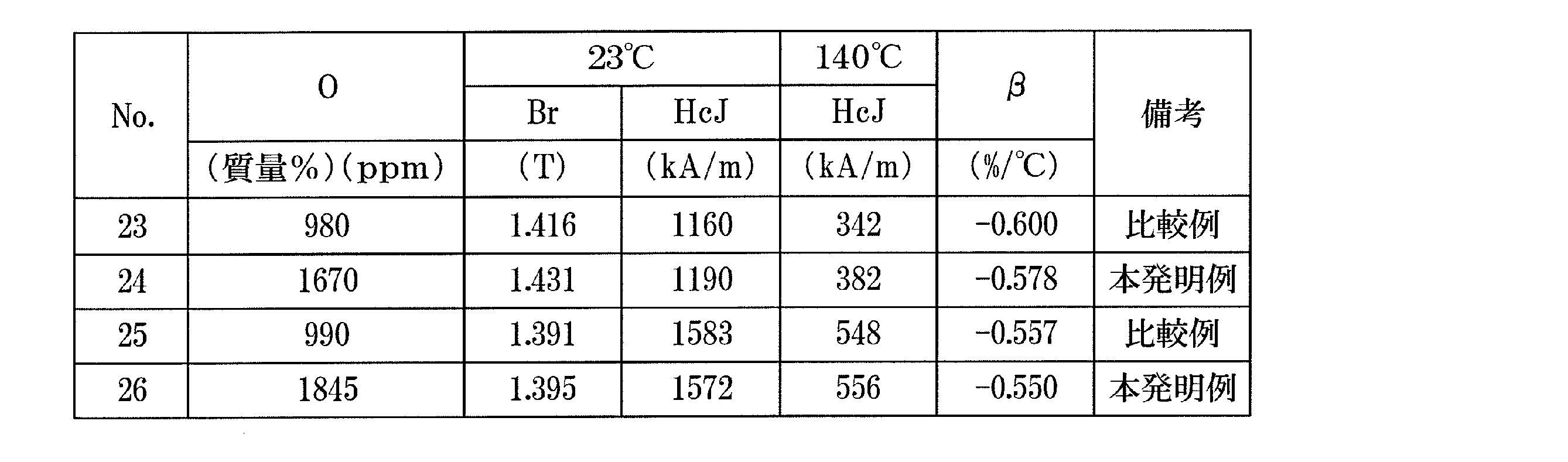
- Table 8 shows the measurement results of the magnetic characteristics of the obtained RTB-based sintered magnet.
- "23 ° C. B r H cJ” in Table 8 is the value of B r and H cJ at room temperature (23 ° C.)
- "140 ° C. H cJ” is the value of H cJ at 140 ° C..
- B r the value of H cJ is by machining the R-T-B based sintered magnet after the heat treatment, processing the sample to 7 mm ⁇ 7 mm ⁇ 7 mm, was measured by BH tracer. Further, the temperature coefficient ( ⁇ : 23 to 140 ° C.) was determined as follows. The H cj at 140 ° C.
- the inventive examples and more 1.391T more B r, and 1190KA / m or more H cj and -0.578 following ⁇ is obtained, is substantially the same composition, No .. 23, 24 and No. Comparing 25 and 26, respectively, the temperature coefficient of the example of the present invention is improved.
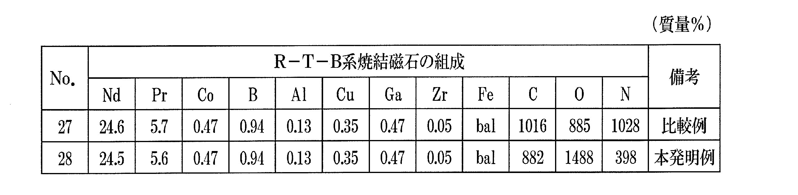
- Example 4 In the same manner as in Example 1, an alloy for RTB-based sintered magnets was prepared so as to have the composition of RTB-based sintered magnets shown in Sample Nos. 27 and 28 in Table 9.
- the obtained RTB-based sintered magnet alloy was coarsely pulverized in the same manner as in Example 1 to obtain a coarse pulverized powder.
- the obtained crude pulverized powder was pulverized in the same manner as in Example 1 to obtain a fine powder.
- the crushing conditions are shown in Table 10.
- the obtained fine pulverization was subjected to molding, sintering, and heat treatment in the same manner as in Example 1 to obtain an RTB-based sintered magnet.
- the components of the obtained sintered magnet were determined in the same manner as in Example 1. The results are shown in Table 9.
- sample No. 27 and 28 have almost the same composition except for O, C, and N.
- the contents of O, C, and N are mass ppm.
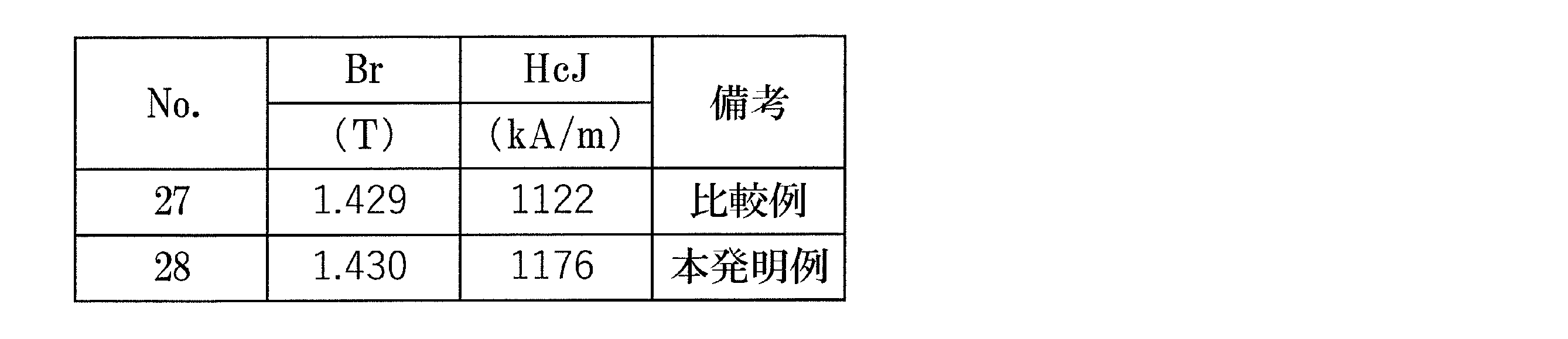
- Table 11 shows the measurement results of the magnetic characteristics of the obtained RTB-based sintered magnet. As shown in Table 11, No. 1 having almost the same composition. Compared with 27 and 28, the example of the present invention (No. 28) has higher magnetic properties.
- the crystal structure of the oxide phase was identified by performing electron diffraction. As a result, No. It was found that both 27 and 28 had a NaCl-type oxide phase in their crystal structure.
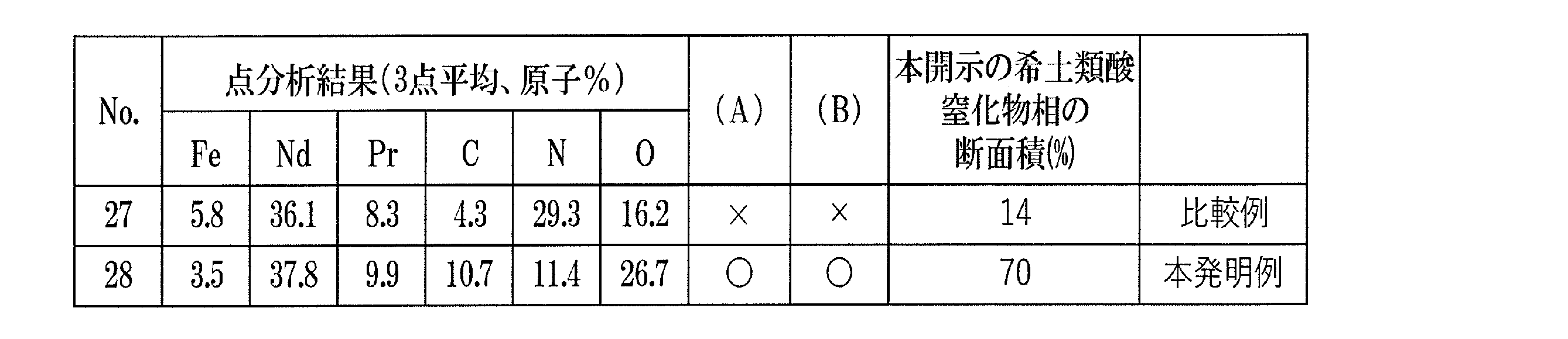
- point analysis and mapping were performed by EDX and WDX. Fe and Nd were analyzed by EDX, Pr, C, N and O by WDX.
- Table 12 shows the average of the oxide phases that were subjected to point analysis at 3 points each.
- Table 12 (A) shows ⁇ N ⁇ when the content of O in the rare earth oxynitride phase (atomic%) is ⁇ O ⁇ and the content of N in the rare earth oxynitride phase is ⁇ N ⁇ .
- the ratio of the rare earth oxynitride phase of the present disclosure was calculated based on the mapping result.
- the mapping intensity of each element was converted into a concentration so as to match the point analysis result using the software "NMap” manufactured by JEOL Ltd.
- a scatter plot analysis was performed using the software "Phase Map Maker” manufactured by JEOL Ltd. Specifically, the region of ⁇ O ⁇ ⁇ 10 atomic% is color-coded as the region of the oxide phase, and then the regions satisfying the formulas (A) and (B) are color-coded to obtain the rare earth oxynitride of the present disclosure. The physical phase and other oxide phases were separated. Then, by counting the number of pixels of each color of the obtained image, the cross-sectional area of the rare earth oxynitride phase of the present disclosure in the rare earth oxide phase was calculated.
- the ratio of the area of the rare earth oxynitride phase of the present disclosure to the area of the rare earth oxide phase is 70%, and (A) and (B). Are satisfied.
- the ratio of the area of the rare earth oxynitride phase of the present disclosure was 14%, which did not satisfy (A) and (B).
- Example 5 Furthermore, the sample No. A diffusion step of diffusing the heavy rare earth element RH from the surface of the sintered body to the inside was performed on the sintered bodies of 27 and 28. Specifically, the raw materials of each element were weighed so as to have the composition of Nd31Pr50Tb9Ga5Cu5 in terms of mass ratio, the raw materials were dissolved, and a diffusion alloy powder was prepared by an atomizing method. No. in Table 1 The sintered bodies of 27 and 28 were cut and ground to obtain a rectangular parallelepiped of 7.2 mm ⁇ 7.2 mm ⁇ 4.7 mm (the direction of 4.7 mm is the direction of applying the magnetic field during molding). Next, No.
- the method for manufacturing the RTB-based sintered magnet of the present disclosure includes various motors such as voice coil motors (VCM) for hard disk drives, motors for electric vehicles (EV, HV, PHV), motors for industrial equipment, and home appliances. It can be used as a permanent magnet used in a wide variety of applications.
- VCM voice coil motors
Landscapes
- Engineering & Computer Science (AREA)
- Power Engineering (AREA)
- Manufacturing & Machinery (AREA)
- Chemical & Material Sciences (AREA)
- Mechanical Engineering (AREA)
- Inorganic Chemistry (AREA)
- Crystallography & Structural Chemistry (AREA)
- Materials Engineering (AREA)
- Metallurgy (AREA)
- Organic Chemistry (AREA)
- Hard Magnetic Materials (AREA)
- Manufacturing Cores, Coils, And Magnets (AREA)
- Manufacture Of Metal Powder And Suspensions Thereof (AREA)
- Powder Metallurgy (AREA)
Abstract
Description
式1:[O]>[C]>[N] 式2:[O]≧1.5×[N] 式3:[C]≧1.5×[N]
式1:[O]>[C]>[N] 式2:[O]≧1.5×[N] 式3:[C]≧1.5×[N]
以下、本開示によるR-T-B系焼結磁石の製造方法の実施形態を説明する。
(1)平均粒度が10μm以上500μm以下のR-T-B系焼結磁石用合金の粗粉砕粉を準備する工程と、
(2)粉砕室が不活性ガスで満たされたジェットミル装置に前記粗粉砕粉を供給して前記粗粉砕粉の粉砕を行い、平均粒度が2.0μm以上4.5μm以下の微粉末を得る工程と、
(3)前記微粉末の焼結体を作製する工程と、
を含み、前記不活性ガスは、加湿されている。平均粒度(d50)は、気流分散式レーザー回折法によって測定され得る。
本開示のR-T-B系焼結磁石は、酸素の含有量が質量割合で1000ppm以上3500ppm以下である。酸素の含有量を1000ppm以上3500ppm以下とすることにより、上記(2)の微粉末を得る工程において、不活性ガスの加湿が弱すぎることで不活性ガスによる粉末粒子の劣化(窒化)が進むことによる磁気特性の低下や加湿による粉末粒子の酸化が進むことによる磁気特性の低下を抑制できる。より高い磁気特性を得るためには、R-T-B系焼結磁石の酸素含有量は1000ppm以上3200ppm以下が好ましく、1000ppm以上2400ppm以下がさらに好ましく、1300ppm以上2400ppm以下がさらに好ましい。また、加湿による粉砕を経て、R-T-B焼結磁石を本開示の酸素の含有量(1000ppm以上3500ppm以上)とすることにより、後述する実施例に示すように成形における圧縮性を向上させることができる。圧縮性が向上することで、より低い成形圧力で成形を行うことができる。これにより、成形体の亀裂発生を抑制することが可能となる。さらに、金型への負荷の低減による連続成形性の向上や金型補修頻度の低減が可能となるため生産効率を向上させることができる。好ましくは、R-T-B系焼結磁石の酸素の含有量は2000ppm以上である。より成形性を向上させることができる。そのため、成形性と磁気特性(BrおよびHcJ)を考慮するとR-T-B系焼結磁石の酸素含有量は2000ppm以上2400ppm以下が好ましい。
式1:[O]>[C]>[N]、式2:[O]≧1.5×[N]、式3:[C]≧1.5×[N]
平均粒度が10μm以上500μm以下のR-T-B系焼結磁石用合金の粗粉砕粉を準備する工程は、R-T-B系焼結磁石用合金を準備する工程と、この合金を例えば水素粉砕法などによって粗く粉砕する工程とを含む。
<粉砕システム>
まず、図1を参照しながら、本開示によるR-T-B系焼結磁石の製造方法に用いられ得る粉砕システムを説明する。図1は、本実施形態における粉砕システム1000の構成例を模式的に示す図である。この例において、R-T-B系焼結磁石合金粉砕システム1000は、ジェットミル装置100と、サイクロン捕集装置200と、バッグフィルタ装置300とを備えている。
好ましい実施形態において、微粉末の焼結体を作製する工程は、磁場中プレスによって前記微粉末から粉末成形体を作製する工程と、この粉末成形体を焼結する工程とを含む。磁場中プレスでは酸化抑制の観点から不活性ガス雰囲気中によるプレスまたは湿式プレスによって粉末成形体を形成する方が好ましい。特に湿式プレスは粉末成形体を構成する粒子の表面が油剤などの分散剤によって被覆され、大気中の酸素や水蒸気との接触が抑制される。このため、プレス工程の前後あるいはプレス工程中に粒子が大気によって酸化されることを防止または抑制することができる。
分散媒は、その内部に合金粉末を分散させることによりスラリーを得ることができる液体である。
得られた合金粉末と分散媒とを混合することでスラリーを得ることができる。
次に、成形体を焼結して希土類焼結磁石体(焼結体)を得る。
式1:[O]>[C]>[N]、式2:[O]≧1.5×[N]、式3:[C]≧1.5×[N]
およそ表1の試料No.1~13に示すR-T-B系焼結磁石の組成となるように(O、C、Nは除く)ストリップキャスト法によりR-T-B系焼結磁石用合金を作製した。得られた各合金を水素粉砕法により粗粉砕し粗粉砕粉を得た。粗粉砕粉の平均粒度を測定した。平均粒度は200μm~400μmの範囲であった。本開示において平均粒度は、小粒径側からの積算粒度分布(体積基準)が50%となる粒径(メジアン径)を意味する。平均粒度(d50)は、Sympatec社製の粒度分布測定装置「HELOS&RODOS」において、分散圧:4bar、測定レンジ:R2、計算モード:HRLD、の条件にて測定した。

実施例1のNo.1~3の焼結体を準備した。前記焼結体に対して、重希土類元素RHを焼結体の表面から内部に拡散する拡散工程をおこなった。具体的には、質量比でPr80Tb10Ga7Cu3の組成となるように各元素の原料を秤量しそれらの原料を溶解して、単ロール超急冷法(メルトスピニング法)によりリボンまたはフレーク状の合金を得た。得られた合金を、アルゴン雰囲気中で粉砕した後、目開き425μmの篩を通過させて拡散合金粉末を準備した。表1のNo.1~3の焼結体を切断、研削加工し、7.2mm×7.2mm×7.2mmの立方体とした。次に、No.1~3の焼結体の全面にR-T-B系焼結磁石の100質量%に対して前記拡散合金を2.5質量%散布した。その後、50Paに制御した減圧アルゴン中で、温度で900℃、10時間の熱処理を行った後室温まで冷却を行い、さらに、50Paに制御した減圧アルゴン中で、500℃3時間の熱処理を行い拡散後のR-T-B系焼結磁石(No.20~23)を作製した。
実施例1と同様にして、表6の試料No.23~26に示すR-T-B系焼結磁石の組成となるようにR-T-B系焼結磁石用合金を作製した。得られたR-T-B系焼結磁石用合金を実施例1と同様にして粗粉砕し、粗粉砕紛を得た。得られた粗粉砕紛を実施例1と同様にして粉砕し、微粉末を得た。粉砕条件を表7に示す。得られた微粉砕を実施例1と同様にして、成形、焼結、熱処理を行い、R-T-B系焼結磁石を得た。得られた焼結磁石の成分を実施例1と同様にして求めた。なお、O、C、Nの含有量は、質量ppmである。結果を表6に示す。表6に示すように、試料No.23と24は、O、C、N以外ほぼ同じ組成である。同様に試料No.25と26もO、C、N以外はほぼ同じ組成である。
温度係数の絶対値が小さいほど温度係数が改善されていることを示している。
実施例1と同様にして、表9の試料No.27および28に示すR-T-B系焼結磁石の組成となるようにR-T-B系焼結磁石用合金を作製した。得られたR-T-B系焼結磁石用合金を実施例1と同様にして粗粉砕し、粗粉砕紛を得た。得られた粗粉砕紛を実施例1と同様にして粉砕し、微粉末を得た。粉砕条件を表10に示す。得られた微粉砕を実施例1と同様にして、成形、焼結、熱処理を行い、R-T-B系焼結磁石を得た。得られた焼結磁石の成分を実施例1と同様にして求めた。結果を表9に示す。

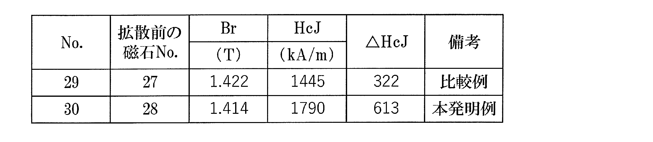
さらに、試料No.27および28の焼結体に対して、重希土類元素RHを焼結体の表面から内部に拡散する拡散工程をおこなった。具体的には、質量比でNd31Pr50Tb9Ga5Cu5の組成となるように各元素の原料を秤量しそれらの原料を溶解して、アトマイズ法により拡散合金粉末を準備した。表1のNo.27および28の焼結体を切断、研削加工し、7.2mm×7.2mm×4.7mm(4.7mmの方向が成形時の磁界印加方向)の直方体とした。次に、No.27および28の焼結体の片面(7.2mm×7.2mmの面)にR-T-B系焼結磁石の100質量%に対して前記拡散合金を2質量%散布した。その後、50Paに制御した減圧アルゴン中で、温度で920℃、10時間の熱処理を行った後室温まで冷却を行い、さらに、50Paに制御した減圧アルゴン中で、450℃で3時間の熱処理を行い拡散後のR-T-B系焼結磁石(No.29および30)を作製した。なお、実施例2と同様にして、拡散後のR-T-B系焼結磁石は、磁石表面から磁石内部に向かってTb濃度が漸減する部分を含んでいることを確認した。
Claims (11)
- R-T-B系焼結磁石(Rは希土類元素であり、Nd、PrおよびCeからなる群から選択される少なくとも1つを必ず含み、Tは遷移金属の少なくとも1つでありFeを必ず含む)の製造方法であって、
平均粒度が10μm以上500μm以下のR-T-B系焼結磁石用合金の粗粉砕粉を準備する工程と、
粉砕室が不活性ガスで満たされたジェットミル装置に前記粗粉砕粉を供給して前記粗粉砕粉の粉砕を行い、平均粒度が2.0μm以上4.5μm以下の微粉末を得る工程と、
前記微粉末の焼結体を作製する工程と、を含み、
前記不活性ガスは加湿されており、前記R-T-B系焼結磁石の酸素の含有量が質量比で1000ppm以上3500ppm以下である、R-T-B系焼結磁石の製造方法。 - 前記R-T-B系焼結磁石のR含有量は31質量%以下である、請求項1に記載のR-T-B系焼結磁石の製造方法。
- 前記不活性ガスは、窒素ガスである、請求項1または2に記載のR-T-B系焼結磁石の製造方法。
- 重希土類元素RH(RHは、Tb、Dy、Hoの少なくとも1つ)を前記焼結体の表面から内部に拡散させる拡散工程を更に含む、請求項1から3のいずれかに記載のR-T-B系焼結磁石の製造方法。
- 前記微粉末の焼結体を作製する工程は、
磁場中湿式プレスまたは不活性ガス雰囲気中による磁場中プレスによって前記微粉末から粉末成形体を作製する工程と、
前記粉末成形体を焼結する工程と、
を含む、請求項1から4のいずれかに記載のR-T-B系焼結磁石の製造方法。 - 前記微粉末を得る工程における前記微粉末の前記平均粒度は2.0μm以上3.5μm以下である、請求項1から5のいずれかに記載のR-T-B系焼結磁石の製造方法。
- R-T-B系焼結磁石であって(Rは希土類元素であり、Nd、PrおよびCeからなる群から選択される少なくとも1つを必ず含み、Tは遷移金属の少なくとも1つでありFeを必ず含む)、
前記R-T-B系焼結磁石の主相であるR2T14B相の平均結晶粒径は、3μm以上7μm以下であり、
酸素、炭素、窒素を含有し、
酸素の含有量は質量比で1000ppm以上3500ppm以下であり、
炭素の含有量は質量比で80ppm以上1500ppm以下であり、
窒素の含有量は質量比で50ppm以上600pm以下であり、
質量比で酸素の含有量を[O]、炭素の含有量を[C]、窒素の含有量を[N]とするとき、以下の式1~3を満足する、R-T-B系焼結磁石。
式1:[O]>[C]>[N]
式2:[O]≧1.5×[N]
式3:[C]≧1.5×[N] - R2T14B化合物からなる主相と、前記主相の粒界部分に位置する粒界相とを含むR-T-B系焼結磁石であって(Rは希土類元素であり、Nd、PrおよびCeからなる群から選択される少なくとも1つを必ず含み、Tは遷移金属の少なくとも1つでありFeを必ず含む)、
前記R-T-B系焼結磁石の主相であるR2T14B相の平均結晶粒径は、3μm以上7μm以下であり、前記R-T-B系焼結磁石は、酸素、炭素、窒素を含有し、
酸素の含有量は質量比で1000ppm以上3500ppm以下であり、
窒素の含有量は質量比で50ppm以上600pm以下であり、
前記粒界相は、希土類酸化物相を有し、
前記希土類酸化物相は、NaCl型結晶構造を有する希土類酸窒化物相を含み、
前記希土類酸窒化物相におけるOの含有量(原子%)を{O}、
前記希土類酸窒化物相におけるNの含有量(原子%)を{N}とするとき、
{O}>1.8×{N}の関係を満たす、
R-T-B系焼結磁石。 - 前記希土類酸窒化物相におけるCの含有量(原子%)を{C}とするとき、
{C}>{N}×0.5の関係を満たす、
請求項8に記載のR-T-B系焼結磁石。 - 前記希土類酸化物相の面積に占める前記希土類酸窒化物相の面積の割合が50%以上である、請求項8または9に記載のR-T-B系焼結磁石。
- 磁石表面から磁石内部に向かってTb濃度およびDy濃度の少なくとも一方が漸減する部分を含む、請求項8から10のいずれか一項に記載のR-T-B系焼結磁石。
Priority Applications (6)
| Application Number | Priority Date | Filing Date | Title |
|---|---|---|---|
| CN202080089947.8A CN114867572B (zh) | 2019-12-26 | 2020-12-24 | R-t-b系烧结磁体的制造方法和r-t-b系烧结磁体 |
| US17/788,325 US12397347B2 (en) | 2019-12-26 | 2020-12-24 | Method for manufacturing R-T-B based sintered magnet, and R-T-B based sintered magnet |
| EP20905090.5A EP4082691B1 (en) | 2019-12-26 | 2020-12-24 | Method for manufacturing r-t-b based sintered magnet, and r-t-b based sintered magnet |
| JP2021532090A JP6947344B1 (ja) | 2019-12-26 | 2020-12-24 | R−t−b系焼結磁石の製造方法およびr−t−b系焼結磁石 |
| JP2021137689A JP7661831B2 (ja) | 2019-12-26 | 2021-08-26 | R-t-b系焼結磁石の製造方法 |
| US19/279,142 US20250345850A1 (en) | 2019-12-26 | 2025-07-24 | Method for manufacturing r-t-b based sintered magnet, and r-t-b based sintered magnet |
Applications Claiming Priority (4)
| Application Number | Priority Date | Filing Date | Title |
|---|---|---|---|
| JP2019-235578 | 2019-12-26 | ||
| JP2019235578 | 2019-12-26 | ||
| JP2020-159614 | 2020-09-24 | ||
| JP2020159614 | 2020-09-24 |
Related Child Applications (2)
| Application Number | Title | Priority Date | Filing Date |
|---|---|---|---|
| US17/788,325 A-371-Of-International US12397347B2 (en) | 2019-12-26 | 2020-12-24 | Method for manufacturing R-T-B based sintered magnet, and R-T-B based sintered magnet |
| US19/279,142 Division US20250345850A1 (en) | 2019-12-26 | 2025-07-24 | Method for manufacturing r-t-b based sintered magnet, and r-t-b based sintered magnet |
Publications (1)
| Publication Number | Publication Date |
|---|---|
| WO2021132476A1 true WO2021132476A1 (ja) | 2021-07-01 |
Family
ID=76575347
Family Applications (1)
| Application Number | Title | Priority Date | Filing Date |
|---|---|---|---|
| PCT/JP2020/048486 Ceased WO2021132476A1 (ja) | 2019-12-26 | 2020-12-24 | R-t-b系焼結磁石の製造方法およびr-t-b系焼結磁石 |
Country Status (5)
| Country | Link |
|---|---|
| US (2) | US12397347B2 (ja) |
| EP (1) | EP4082691B1 (ja) |
| JP (2) | JP6947344B1 (ja) |
| CN (1) | CN114867572B (ja) |
| WO (1) | WO2021132476A1 (ja) |
Cited By (2)
| Publication number | Priority date | Publication date | Assignee | Title |
|---|---|---|---|---|
| WO2023280259A1 (zh) * | 2021-07-08 | 2023-01-12 | 烟台正海磁性材料股份有限公司 | 一种耐腐蚀、高性能钕铁硼烧结磁体及其制备方法和用途 |
| WO2023181770A1 (ja) * | 2022-03-22 | 2023-09-28 | 株式会社プロテリアル | R-t-b系焼結磁石 |
Families Citing this family (3)
| Publication number | Priority date | Publication date | Assignee | Title |
|---|---|---|---|---|
| CN118299137B (zh) * | 2022-10-31 | 2025-12-09 | 福建省金龙稀土股份有限公司 | 一种r-t-b系永磁体及其制备方法和应用 |
| CN115886107A (zh) * | 2022-11-23 | 2023-04-04 | 杭州浙大百川生物食品技术有限公司 | 一种龙井干茶中香露提取方法 |
| CN118197728A (zh) * | 2022-12-13 | 2024-06-14 | 烟台正海磁性材料股份有限公司 | R-t-b系永磁材料及其制备方法和应用 |
Citations (8)
| Publication number | Priority date | Publication date | Assignee | Title |
|---|---|---|---|---|
| JPH04287304A (ja) * | 1991-03-15 | 1992-10-12 | Tdk Corp | 永久磁石の製造方法 |
| JPH06140220A (ja) | 1992-10-22 | 1994-05-20 | Sumitomo Special Metals Co Ltd | 希土類磁石用原料粉末の製造方法 |
| JPH08148317A (ja) | 1994-11-24 | 1996-06-07 | Shin Etsu Chem Co Ltd | 希土類磁石の製造方法 |
| JPH1022154A (ja) * | 1996-06-28 | 1998-01-23 | Shin Etsu Chem Co Ltd | 希土類磁石の製造方法 |
| JP2011060975A (ja) * | 2009-09-09 | 2011-03-24 | Nissan Motor Co Ltd | 磁石成形体およびその製造方法 |
| JP2012158792A (ja) * | 2011-01-31 | 2012-08-23 | Hitachi Metals Ltd | 希土類系磁石用原料合金の水素粉砕粉の回収方法及び回収装置 |
| JP2018142641A (ja) * | 2017-02-28 | 2018-09-13 | 日立金属株式会社 | R−t−b系焼結磁石の製造方法 |
| JP2019169506A (ja) * | 2018-03-22 | 2019-10-03 | 日立金属株式会社 | R−t−b系焼結磁石及びその製造方法 |
Family Cites Families (8)
| Publication number | Priority date | Publication date | Assignee | Title |
|---|---|---|---|---|
| US5858123A (en) | 1995-07-12 | 1999-01-12 | Hitachi Metals, Ltd. | Rare earth permanent magnet and method for producing the same |
| JP2002175931A (ja) * | 2000-09-28 | 2002-06-21 | Sumitomo Special Metals Co Ltd | 希土類磁石およびその製造方法 |
| JP2006100847A (ja) | 2005-11-14 | 2006-04-13 | Tdk Corp | R−t−b系希土類永久磁石 |
| CN103050267B (zh) * | 2012-12-31 | 2016-01-20 | 厦门钨业股份有限公司 | 一种基于细粉热处理的烧结Nd-Fe-B系磁铁制作方法 |
| JP6094612B2 (ja) * | 2014-02-28 | 2017-03-15 | 日立金属株式会社 | R−t−b系焼結磁石の製造方法 |
| US10984930B2 (en) * | 2017-09-28 | 2021-04-20 | Hitachi Metals, Ltd. | Method for producing sintered R—T—B based magnet and diffusion source |
| CN207992914U (zh) * | 2018-01-04 | 2018-10-19 | 钦州学院 | 基于草鱼鱼鳞微观表面的微型散热器 |
| JP7155813B2 (ja) * | 2018-03-22 | 2022-10-19 | 日立金属株式会社 | R-t-b系焼結磁石の製造方法 |
-
2020
- 2020-12-24 WO PCT/JP2020/048486 patent/WO2021132476A1/ja not_active Ceased
- 2020-12-24 US US17/788,325 patent/US12397347B2/en active Active
- 2020-12-24 JP JP2021532090A patent/JP6947344B1/ja active Active
- 2020-12-24 EP EP20905090.5A patent/EP4082691B1/en active Active
- 2020-12-24 CN CN202080089947.8A patent/CN114867572B/zh active Active
-
2021
- 2021-08-26 JP JP2021137689A patent/JP7661831B2/ja active Active
-
2025
- 2025-07-24 US US19/279,142 patent/US20250345850A1/en active Pending
Patent Citations (8)
| Publication number | Priority date | Publication date | Assignee | Title |
|---|---|---|---|---|
| JPH04287304A (ja) * | 1991-03-15 | 1992-10-12 | Tdk Corp | 永久磁石の製造方法 |
| JPH06140220A (ja) | 1992-10-22 | 1994-05-20 | Sumitomo Special Metals Co Ltd | 希土類磁石用原料粉末の製造方法 |
| JPH08148317A (ja) | 1994-11-24 | 1996-06-07 | Shin Etsu Chem Co Ltd | 希土類磁石の製造方法 |
| JPH1022154A (ja) * | 1996-06-28 | 1998-01-23 | Shin Etsu Chem Co Ltd | 希土類磁石の製造方法 |
| JP2011060975A (ja) * | 2009-09-09 | 2011-03-24 | Nissan Motor Co Ltd | 磁石成形体およびその製造方法 |
| JP2012158792A (ja) * | 2011-01-31 | 2012-08-23 | Hitachi Metals Ltd | 希土類系磁石用原料合金の水素粉砕粉の回収方法及び回収装置 |
| JP2018142641A (ja) * | 2017-02-28 | 2018-09-13 | 日立金属株式会社 | R−t−b系焼結磁石の製造方法 |
| JP2019169506A (ja) * | 2018-03-22 | 2019-10-03 | 日立金属株式会社 | R−t−b系焼結磁石及びその製造方法 |
Non-Patent Citations (1)
| Title |
|---|
| See also references of EP4082691A4 |
Cited By (2)
| Publication number | Priority date | Publication date | Assignee | Title |
|---|---|---|---|---|
| WO2023280259A1 (zh) * | 2021-07-08 | 2023-01-12 | 烟台正海磁性材料股份有限公司 | 一种耐腐蚀、高性能钕铁硼烧结磁体及其制备方法和用途 |
| WO2023181770A1 (ja) * | 2022-03-22 | 2023-09-28 | 株式会社プロテリアル | R-t-b系焼結磁石 |
Also Published As
| Publication number | Publication date |
|---|---|
| US20230040720A1 (en) | 2023-02-09 |
| JPWO2021132476A1 (ja) | 2021-12-23 |
| JP7661831B2 (ja) | 2025-04-15 |
| JP2022023024A (ja) | 2022-02-07 |
| JP6947344B1 (ja) | 2021-10-13 |
| EP4082691A1 (en) | 2022-11-02 |
| US12397347B2 (en) | 2025-08-26 |
| EP4082691B1 (en) | 2025-07-16 |
| US20250345850A1 (en) | 2025-11-13 |
| EP4082691A4 (en) | 2024-01-03 |
| CN114867572B (zh) | 2025-01-24 |
| CN114867572A (zh) | 2022-08-05 |
Similar Documents
| Publication | Publication Date | Title |
|---|---|---|
| JP6947344B1 (ja) | R−t−b系焼結磁石の製造方法およびr−t−b系焼結磁石 | |
| JP6798546B2 (ja) | R−t−b系焼結磁石の製造方法 | |
| WO2019151244A1 (ja) | 永久磁石 | |
| JP7810162B2 (ja) | R-Fe-B系焼結磁石 | |
| JP7537536B2 (ja) | R-t-b系焼結磁石 | |
| WO2022209466A1 (ja) | R-t-b系焼結磁石の製造方法 | |
| WO2021117672A1 (ja) | 希土類焼結磁石 | |
| JP7707703B2 (ja) | R-t-b系焼結磁石の製造方法 | |
| JP7600531B2 (ja) | R-t-b系焼結磁石の製造方法 | |
| JP7632118B2 (ja) | R-t-b系焼結磁石の製造方法 | |
| JP2022174820A (ja) | 希土類焼結磁石及び希土類焼結磁石の製造方法 | |
| JP7746764B2 (ja) | R-t-b系焼結磁石の製造方法 | |
| JP2025055176A (ja) | 希土類焼結磁石の製造方法 | |
| JP7226281B2 (ja) | 希土類焼結磁石 | |
| JP2025055177A (ja) | 希土類焼結磁石の製造方法 | |
| WO2024225313A1 (ja) | R-t-b系焼結磁石 | |
| US20240112854A1 (en) | Method for recycling rare earth element-containing powder, and method for producing rare earth sintered magnet | |
| JP2025179463A (ja) | 希土類焼結磁石及びその製造方法 | |
| JP2025055178A (ja) | 希土類焼結磁石の製造方法 | |
| CN114649125A (zh) | R-t-b系烧结磁体的制造方法 | |
| CN114730652A (zh) | R-Fe-B系烧结磁体 | |
| JP2021153148A (ja) | R−t−b系焼結磁石の製造方法及び拡散用合金 |
Legal Events
| Date | Code | Title | Description |
|---|---|---|---|
| ENP | Entry into the national phase |
Ref document number: 2021532090 Country of ref document: JP Kind code of ref document: A |
|
| 121 | Ep: the epo has been informed by wipo that ep was designated in this application |
Ref document number: 20905090 Country of ref document: EP Kind code of ref document: A1 |
|
| NENP | Non-entry into the national phase |
Ref country code: DE |
|
| ENP | Entry into the national phase |
Ref document number: 2020905090 Country of ref document: EP Effective date: 20220726 |
|
| WWG | Wipo information: grant in national office |
Ref document number: 202080089947.8 Country of ref document: CN |
|
| WWG | Wipo information: grant in national office |
Ref document number: 2020905090 Country of ref document: EP |
|
| WWG | Wipo information: grant in national office |
Ref document number: 17788325 Country of ref document: US |