WO2021134386A1 - 一种通信方法、通信装置和系统 - Google Patents
一种通信方法、通信装置和系统 Download PDFInfo
- Publication number
- WO2021134386A1 WO2021134386A1 PCT/CN2019/130272 CN2019130272W WO2021134386A1 WO 2021134386 A1 WO2021134386 A1 WO 2021134386A1 CN 2019130272 W CN2019130272 W CN 2019130272W WO 2021134386 A1 WO2021134386 A1 WO 2021134386A1
- Authority
- WO
- WIPO (PCT)
- Prior art keywords
- data channel
- information
- bwp
- domain resource
- time domain
- Prior art date
- Legal status (The legal status is an assumption and is not a legal conclusion. Google has not performed a legal analysis and makes no representation as to the accuracy of the status listed.)
- Ceased
Links
Images


Classifications
-
- H—ELECTRICITY
- H04—ELECTRIC COMMUNICATION TECHNIQUE
- H04W—WIRELESS COMMUNICATION NETWORKS
- H04W72/00—Local resource management
- H04W72/04—Wireless resource allocation
- H04W72/044—Wireless resource allocation based on the type of the allocated resource
- H04W72/0446—Resources in time domain, e.g. slots or frames
-
- H—ELECTRICITY
- H04—ELECTRIC COMMUNICATION TECHNIQUE
- H04W—WIRELESS COMMUNICATION NETWORKS
- H04W72/00—Local resource management
- H04W72/50—Allocation or scheduling criteria for wireless resources
- H04W72/51—Allocation or scheduling criteria for wireless resources based on terminal or device properties
-
- H—ELECTRICITY
- H04—ELECTRIC COMMUNICATION TECHNIQUE
- H04L—TRANSMISSION OF DIGITAL INFORMATION, e.g. TELEGRAPHIC COMMUNICATION
- H04L5/00—Arrangements affording multiple use of the transmission path
- H04L5/0001—Arrangements for dividing the transmission path
- H04L5/0003—Two-dimensional division
- H04L5/0005—Time-frequency
- H04L5/0007—Time-frequency the frequencies being orthogonal, e.g. OFDM(A) or DMT
- H04L5/001—Time-frequency the frequencies being orthogonal, e.g. OFDM(A) or DMT the frequencies being arranged in component carriers
-
- H—ELECTRICITY
- H04—ELECTRIC COMMUNICATION TECHNIQUE
- H04L—TRANSMISSION OF DIGITAL INFORMATION, e.g. TELEGRAPHIC COMMUNICATION
- H04L5/00—Arrangements affording multiple use of the transmission path
- H04L5/003—Arrangements for allocating sub-channels of the transmission path
- H04L5/0044—Allocation of payload; Allocation of data channels, e.g. PDSCH or PUSCH
-
- H—ELECTRICITY
- H04—ELECTRIC COMMUNICATION TECHNIQUE
- H04L—TRANSMISSION OF DIGITAL INFORMATION, e.g. TELEGRAPHIC COMMUNICATION
- H04L5/00—Arrangements affording multiple use of the transmission path
- H04L5/0091—Signalling for the administration of the divided path, e.g. signalling of configuration information
- H04L5/0094—Indication of how sub-channels of the path are allocated
-
- H—ELECTRICITY
- H04—ELECTRIC COMMUNICATION TECHNIQUE
- H04W—WIRELESS COMMUNICATION NETWORKS
- H04W48/00—Access restriction; Network selection; Access point selection
- H04W48/08—Access restriction or access information delivery, e.g. discovery data delivery
- H04W48/12—Access restriction or access information delivery, e.g. discovery data delivery using downlink control channel
-
- H—ELECTRICITY
- H04—ELECTRIC COMMUNICATION TECHNIQUE
- H04W—WIRELESS COMMUNICATION NETWORKS
- H04W72/00—Local resource management
- H04W72/04—Wireless resource allocation
- H04W72/044—Wireless resource allocation based on the type of the allocated resource
- H04W72/0453—Resources in frequency domain, e.g. a carrier in FDMA
-
- H—ELECTRICITY
- H04—ELECTRIC COMMUNICATION TECHNIQUE
- H04W—WIRELESS COMMUNICATION NETWORKS
- H04W72/00—Local resource management
- H04W72/20—Control channels or signalling for resource management
- H04W72/23—Control channels or signalling for resource management in the downlink direction of a wireless link, i.e. towards a terminal
Definitions
- This application relates to the field of wireless communication technology, and in particular to a communication method and communication device.
- NR-light terminal equipment has a lower bandwidth processing capacity, so it takes up less bandwidth resources.
- the present application provides a communication method, communication device, and system, so that NR-light terminal devices can obtain their own system information block (SIB) with low overhead, and the technical solutions disclosed in the embodiments of the present application are good Forward compatibility.
- SIB system information block
- a communication method provided by an embodiment of the present application includes:
- the network device sends downlink control information (DCI) to the first terminal device, where the DCI includes: time domain resource information, and the time domain resource information is used to determine the time domain resource, and the time domain resource is the first The time domain resource where the data channel is located; frequency domain resource information, the frequency domain resource information is used to determine the frequency domain resource, the frequency domain resource is the frequency domain resource where the first data channel is located and the frequency domain resource where the second data channel is located Frequency domain resources; the second data channel is located on a time domain resource different from the time domain resource where the first data channel is located; the first terminal device is on the determined time domain resource and the frequency domain resource , Receiving a signal from the network device located on the first data channel; wherein the first data channel is used for the first terminal device to communicate with the network device; the second data channel is used for The second terminal device communicates with the network device.
- DCI downlink control information
- the communication referred to above may be uplink communication and/or downlink communication.
- uplink communication and/or downlink communication please refer to the relevant content in the specific implementation of this application.
- the time domain resource information includes: time domain offset information, and the time domain offset information is used to determine the time domain interval between the time unit where the DCI is located and the first time unit, so
- the first time unit is the time unit where the first data channel is located; time domain start position information, the time domain start position information is used to determine a first position, and the first position shown is the first data
- the channel is at the time domain start position of the first time unit; duration information, where the duration information is used to determine a first duration, and the first duration shown is that the first data channel is in the first time unit The length of time occupied.
- the first position is also the time domain start position of the second data channel in a second time unit, and the second time unit is the time when the second data channel is located. Unit; the first time length is also the time length occupied by the second data channel in the second time unit.
- the first data channel is located in a first bandwidth part (BWP), and the DCI and the second data channel are located in a second BWP.
- the DCI also includes BWP information, and the BWP information is used to determine the first BWP.
- the method further includes: the first terminal device receives the signal located on the first data channel from the network device on the determined first BWP.
- the first data channel is located at a different BWP from the DCI and the second data channel. Since the first data channel of the first terminal device is located in a second BWP that is different from the second data channel of the second terminal device, the first terminal device and the second terminal device can complete the remaining initial access procedures and procedures on different BWPs.
- the random access process reduces the number of terminal devices that perform random access on the same BWP, thereby effectively reducing the collision probability of random access on the same BWP.
- the first terminal device switches to a second BWP different from the first BWP, if the network device wants to page the terminal device communicating on the second BWP, the first terminal device will not receive Unnecessary paging messages make paging more targeted and reduce the overhead of the entire system.
- the BWP information includes: BWP offset information, the BWP offset information, and the first BWP bandwidth information, or the first BWP start position information and the first BWP Bandwidth information;
- the BWP offset information is used to determine the frequency domain interval between the second BWP and the first BWP;
- the first BWP bandwidth information is used to determine the bandwidth occupied by the first BWP;
- a BWP start position information is used to determine the frequency domain start position of the first BWP.
- This design embodies the flexibility of BWP information configuration.
- the time domain resource information corresponds to 0 bits
- the time domain resource is predefined. This design can save system overhead to the utmost extent.
- the first terminal device and the second terminal device are different types of terminal devices.
- the first terminal device is an NR-light terminal device
- the second terminal is a normal terminal device.
- the signal on the first data channel includes a system message.
- the first data channel may be a physical downlink shared channel (PDSCH) that carries system messages.
- PDSCH physical downlink shared channel
- the DCI further includes confirmation information, and the confirmation information is used to determine that the second data channel is located in a time domain resource different from a time domain resource where the first data channel is located.
- At least one of the following is located in the reserved domain of the DCI: the time domain offset information, the time domain start position information, the duration information, the BWP information, and the The confirmation information. This reflects good forward compatibility.
- the above technical solution enables the NR-light terminal device to obtain its own SIB with low overhead by multiplexing at least part of the information of the ordinary terminal device, and the method has good forward compatibility.
- an embodiment of the present application provides a communication method, including:
- the network device sends the DCI to the first terminal device on the second BWP, where the DCI includes BWP information, and the BWP information is used to determine the first BWP, and the first data channel is located in the first BWP.
- the first terminal device receives the signal from the network device located on the first data channel on the determined first BWP.
- the BWP information includes: BWP offset information, the BWP offset information, and the first BWP bandwidth information, or the first BWP start position information and the first BWP Bandwidth information.
- the BWP offset information is used to determine the frequency domain interval between the second BWP and the first BWP;
- the first BWP bandwidth information is used to determine the bandwidth occupied by the first BWP;
- a BWP start position information is used to determine the frequency domain start position of the first BWP.
- This design embodies the flexibility of BWP information configuration.
- the first terminal device also needs to determine the specific time domain resources and frequency domain resources of the first data channel on the first BWP.
- the specific method for determining the time domain resource and the frequency domain resource is the method for determining the time domain resource and the frequency domain resource of the first data channel in the first aspect.
- the first terminal device can reuse the information of the existing frequency domain resource allocation and time domain resource allocation fields in the DCI, that is, the second data channel in the same BWP, the second BWP, and the DCI
- the time-frequency resource of is determined as the time-frequency resource of the first data channel in the first BWP.
- the second data channel is used for communication between the network device and the second terminal device.
- the first terminal device and the second terminal device are different types of terminal devices.
- the first terminal device is an NR-light terminal device
- the second terminal is a normal terminal device.
- the first terminal device uses the same method as determining the frequency domain resource of the second data channel in the second BWP to determine the frequency domain resource of the first data channel in the first BWP;
- the first terminal device determines that the frequency domain resource of the first data channel is the first BWP Bandwidth.
- the start position of the frequency domain resource determined by the frequency domain allocation field of the first terminal device is the start position of the first BWP
- the length of the frequency domain resource is the length determined by the frequency domain allocation field
- the design is very good for forward compatibility.
- the signal on the first data channel includes a system message.
- the first data channel may be a physical downlink shared channel that carries system messages.
- the DCI further includes confirmation information, and the confirmation information is used to determine that the second data channel is located in a time domain resource different from a time domain resource where the first data channel is located.
- the above technical solution not only realizes that the same DCI indicates the data channels of two different types of terminal devices, but also ensures the forward compatibility. Further, because the first data channel of the first terminal device is located in a second BWP that is different from the second data channel of the second terminal device, that is, the first terminal device and the second terminal device complete the remaining BWP on different BWPs.
- the initial access process and random access process reduce the number of terminal devices that perform random access on the same BWP, thereby effectively reducing the collision probability of random access on the same BWP.
- the first terminal device will not receive unnecessary paging. Paging messages, which makes paging more targeted and reduces the overhead of the entire system.
- an embodiment of the present application provides a communication method, including:
- the network device sends DCI to the first terminal device on the second BWP.
- the DCI includes first information.
- the first information is used to determine the first BWP where the first data channel is located and where the first data channel is located. Describe the time-frequency resources of the first BWP.
- the first terminal device receives the signal from the network device located on the first data channel on the determined first BWP.
- the second BWP is different from the first BWP.
- the first terminal device may determine the first BWP and the time-frequency resource of the first data channel in the first BWP according to the DCI.
- the signal is a system message.
- the first terminal device initiates a random access procedure to the network device according to the system message, and/or receives a paging signal from the network device.
- the first information includes: BWP information, time domain resource information, and frequency domain resource information.
- the time domain resource information may further include: time domain offset information, time domain start position information, and duration information.
- the above information is all indicated through newly added fields.
- the first information includes: BWP information, the BWP information is used to determine the first BWP; time domain offset information, the time domain offset information is used to determine the DCI
- an embodiment of the present application provides a communication method, including:
- the network device sends downlink control information DCI to the first terminal device, where the DCI is used to indicate the time-frequency resource of the second data channel of the second terminal device, and the second data channel is located in the first resource in the first time unit;
- the first terminal device receives the signal of the first data channel of the first terminal on the second resource in the first time unit; wherein the second resource is the second resource in the first time unit. The remaining part of the first resource.
- an embodiment of the present application provides a communication method, including:
- the network device sends downlink control information DCI to the first terminal device, where the DCI includes: time domain resource information, where the time domain resource information is used to determine a first time domain resource, and the first time domain resource is the first The first time unit where the data channel is located; frequency domain resource information, where the frequency domain resource information is used to determine a first frequency domain resource, the first frequency domain resource is the resource resource where the first data channel is located, and the first 2. Resource resources where the data channel is located; the second data channel is located in the first time unit and the frequency domain resources of the first data channel and the second data channel do not overlap;
- the first terminal device receives the signal located on the first data channel from the network device on the determined first time domain resource and first frequency domain resource.
- an embodiment of the present application provides a communication method, including:
- the downlink control information DCI is sent from the network device to the first terminal device, where the DCI includes: time domain resource information, and the frequency domain resource information is used to determine a first frequency domain resource, and the first frequency domain resource is the first frequency domain resource.
- an embodiment of the present application provides a communication method, including:
- the network device sends downlink control information DCI to the first terminal device, where the DCI includes: frequency domain resource information, where the frequency domain resource information is used to determine a first frequency domain resource, and the first frequency domain resource is the first The frequency domain resource where the data channel is located; time domain resource information, where the time domain resource information is used to determine a first time domain resource, and the first time domain resource is the time domain resource where the first data channel is located; The second data channel and the first data channel are located in the same time unit, and the time-frequency resources of the first data channel and the time-frequency domain resources of the second data channel do not overlap; On the first time domain resource and the first frequency domain resource, a signal located on the first data channel from the network device is received.
- the DCI includes: frequency domain resource information, where the frequency domain resource information is used to determine a first frequency domain resource, and the first frequency domain resource is the first The frequency domain resource where the data channel is located; time domain resource information, where the time domain resource information is used to determine a first time domain resource, and the first time
- the above first data channel is used for the first terminal device to communicate with the network device; the second data channel is used for the second terminal device to communicate with the network device.
- the first terminal device and the second terminal device are different types of terminal devices.
- the first terminal device is an NR-light terminal device
- the second terminal is a normal terminal device.
- the first data channel and the second data channel are not only located in the same BWP, but the first data channel and the second data channel are also located in the same time unit, and these methods ensure that the first data channel and the second data channel are located in the same time unit.
- the communication between a terminal device and the network device on the first data channel and the communication between the second terminal device and the network device on the second data channel do not interfere with each other.
- an embodiment of the present application provides a communication device.
- the communication device may be the aforementioned first terminal device or a device (for example, a chip) located in the first terminal device.
- the communication device may include a corresponding functional module or circuit for executing the method executed by the first terminal device in any possible design of the first aspect to the seventh aspect or any one of the first aspect to the seventh aspect.
- an embodiment of the present application provides a communication device, which may be the aforementioned network device or a device (for example, a chip) located in the network device.
- the communication device may include a corresponding functional module or circuit, which is used to execute the method executed by the network device in any one of the possible designs from the first aspect to the seventh aspect or any one of the first aspect to the seventh aspect.
- an embodiment of the present application provides a communication device, the communication device includes a processor, configured to implement any possible design of the first aspect to the seventh aspect or the first aspect to the seventh aspect The function of the first terminal device in the.
- the communication device may also include a memory for storing instructions and data.
- the memory is coupled with the processor, and when the processor executes the program instructions stored in the memory, the function of the above-mentioned first terminal device can be realized.
- the communication device may also include a communication interface for the communication device to communicate with other devices.
- the communication interface may be a transceiver (including an antenna), a circuit, a bus, or other types of communication interfaces, Other devices can be network devices and so on.
- an embodiment of the present application provides a communication device, the communication device including a processor, configured to implement any one of the above-mentioned first aspect to the seventh aspect or the first aspect to the seventh aspect.
- the communication device may also include a memory for storing instructions and data.
- the memory is coupled with the processor, and when the processor executes the program instructions stored in the memory, the function of the above-mentioned network device can be realized.
- the communication device may also include a communication interface for the communication device to communicate with other devices.
- the communication interface may be a transceiver (including an antenna), a circuit, a bus, or other types of communication interfaces, Other devices can be terminal devices and so on.
- the embodiments of the present application also provide a computer-readable storage medium that stores instructions in the storage medium.
- the instructions When the instructions are executed, the first aspect to the seventh aspect or the first aspect to the first aspect can be implemented.
- the function of the first terminal device in any possible design of the seventh aspect.
- the embodiments of the present application also provide a computer-readable storage medium that stores instructions in the storage medium.
- the instructions When the instructions are executed, the first aspect to the seventh aspect or the first aspect to the first aspect can be implemented.
- the function of the network device in any possible design of the seventh aspect.
- the embodiments of the present application also provide a chip system, which includes a processor and a memory composed of an integrated circuit, and is used to implement the aspects of the first aspect to the seventh aspect or the first aspect to the seventh aspect.
- the function of the first terminal device in any possible design.
- the chip system can be composed of chips, and can also include chips and other discrete devices.
- the embodiments of the present application also provide a chip system, which includes a processor and a memory composed of integrated circuits, and is used to implement any of the first to seventh aspects or any of the first to seventh aspects.
- a chip system which includes a processor and a memory composed of integrated circuits, and is used to implement any of the first to seventh aspects or any of the first to seventh aspects.
- the chip system can be composed of chips, or it can include chips and other discrete devices.
- the embodiments of the present application also provide a computer program product, including instructions.
- the instructions When the instructions are executed by a communication device, the communication device can implement the first aspect to the seventh aspect or the first aspect to the seventh aspect. Aspects of the function of the first terminal device in any possible design.
- the embodiments of the present application also provide a computer program product, including an instruction, when the instruction is executed by a communication device, it can implement any of the first to seventh aspects or the first to seventh aspects.
- a computer program product including an instruction, when the instruction is executed by a communication device, it can implement any of the first to seventh aspects or the first to seventh aspects.
- an embodiment of the present application further provides a communication system, including the communication device of the eighth aspect and the communication device of the ninth aspect. Or include the communication device of the tenth aspect and the communication device of the eleventh aspect.
- FIG. 1 is a schematic diagram of a communication system architecture provided by an embodiment of the application
- FIG. 3 is a schematic diagram of a terminal device access process provided by an embodiment of this application.
- FIG. 4 is a schematic diagram of another communication system architecture provided by an embodiment of the application.
- FIG. 5 is a schematic diagram of a communication method provided in Embodiment 1 of this application.
- FIG. 6 is a schematic diagram of a data channel indication method provided by an embodiment of the application.
- FIG. 7 is a schematic diagram of a communication method provided in Embodiment 2 of this application.
- FIG. 8 is a schematic diagram of another data channel indication manner provided by an embodiment of the application.
- FIG. 10 is a schematic diagram of a communication method provided in Embodiment 3 of this application.
- FIG. 11(a)-(d) are schematic diagrams of the location of time domain resources in the fourth embodiment of this application.
- FIG. 12 is a schematic diagram of another data channel indication mode according to an embodiment of the application.
- FIG. 13 is a schematic structural diagram of a device provided by an embodiment of this application.
- FIG. 14 is a schematic structural diagram of another device provided by an embodiment of the application.
- FIG. 15 is a schematic structural diagram of an electronic device provided by an embodiment of this application.
- At least one refers to one or more.
- Multiple means two or more.
- At least one (item) of " or similar expressions refers to any combination of these items, including any combination of single items (items) or plural items (items).
- at least one item (a) of a, b, or c can represent: a, b, c, a and b, a and c, b and c, or a, b and c.
- each of a, b, and c can be an element itself, or a collection containing one or more elements.
- “And/or” describes the association relationship of the associated objects, indicating that there can be three types of relationships.
- a and/or B can mean: A alone exists, A and B exist at the same time, and B exists alone. Among them, A and B can be singular or plural.
- transmission can include sending, receiving, or sending and receiving, and can be a noun or a verb.
- Words such as “first” and “second” involved in the embodiments of the present application are only used for the purpose of distinguishing description, and cannot be understood as indicating or implying relative importance, nor as indicating or implying order.
- FIG. 1 is a schematic diagram of the architecture of a communication system to which the embodiments of this application are applicable.
- the terminal device 1 and the terminal device 2 can access one or more wireless networks through a network device 10, and perform uplink communication and/or downlink communication with the wireless network through the network device 10.
- the wireless network includes but is not limited to: long term evolution (LTE) system, NR (new radio) system in the fifth generation (5th generation, 5G) mobile communication system, and other existing or future Mobile communication system, etc.
- LTE long term evolution
- NR new radio
- Terminal device terminal device
- the terminal device in the embodiment of this application is a device with wireless transceiver function, which can be referred to as a terminal (terminal) for short, and can also be referred to as a user equipment (UE), a mobile station (MS), or a mobile terminal. (mobile terminal, MT), vehicle-mounted terminal equipment, remote station, remote terminal equipment, etc.
- the terminal device can be fixed or mobile.
- the specific form of the terminal device can be, for example, mobile phone, cellular phone, cordless phone, session initiation protocol (SIP) phone, wearable device, tablet computer (pad), desktop personal computer, notebook computer , Vehicle-mounted terminal, wireless local loop (WLL) station, personal digital assistant (personal digital assistant, PDA), etc.
- SIP session initiation protocol
- WLL wireless local loop
- PDA personal digital assistant
- terminal equipment can also be applied to the following scenarios: virtual reality (VR), augmented reality (AR), industrial control (industrial control), and self-driving (self-driving) ), remote surgery (remote medical surgery), smart grid (smart grid), transportation safety (transportation safety), smart city (smart city), smart home (smart home), etc.
- VR virtual reality
- AR augmented reality
- industrial control industrial control
- self-driving self-driving
- remote surgery remote surgery
- smart grid smart grid
- transportation safety transportation safety
- smart city smart city
- smart home smart home
- the terminal device supports at least one wireless communication technology, such as LTE, NR, and wideband code division multiple access (WCDMA).
- WCDMA wideband code division multiple access
- the NR-light terminal equipment mentioned earlier in this article can also be referred to as reduced capability (REDCAP) terminal equipment, which can be sensors or wearable devices, etc., and its characteristics can be: Compared with other terminal equipment, their manufacturing cost is lower. Low, and the communication bandwidth with network equipment is low, and the power consumption is also low.
- REDCAP reduced capability
- the network device in the embodiment of the present application is a device that provides wireless communication functions for terminal devices, and may also be referred to as a radio access network (RAN) device.
- network equipment includes but is not limited to: next generation nodeB (gNB) in 5G mobile communication system, evolved node B (evolved node B, eNB) in LTE system, baseband unit (BBU) ), transmitting and receiving point (TRP), transmitting point (TP), relay station, access point, etc.
- the network equipment may also be a wireless controller, a centralized unit (CU), a distributed unit (DU), etc. in a cloud radio access network (cloud radio access network, CRAN) scenario.
- the network device supports at least one wireless communication technology, such as LTE, NR, WCDMA, etc.
- uplink communication in the embodiments of the present application may also be referred to as uplink transmission, which refers to a process in which the terminal device sends a signal to the network device in the communication between the terminal device and the network device.
- the signal sent by the terminal device to the network device may be referred to as an uplink signal or uplink information.
- the uplink signal includes uplink control information (UCI) and uplink data.
- the uplink control information is used to carry related information fed back by the terminal equipment, such as channel state information (CSI), acknowledgement (acknowledgement, ACK) or negative acknowledgement (NACK), etc.
- the uplink control information can be carried on a physical uplink control channel (PUCCH), or can be carried on a physical uplink shared channel (PUSCH); the uplink data can be carried on the PUSCH.
- PUCCH physical uplink control channel
- PUSCH physical uplink shared channel
- the downlink communication in the embodiments of the present application may also be referred to as downlink transmission, which refers to a process in which the terminal device receives a signal sent by the network device in the communication between the terminal device and the network device.
- the terminal device receiving the signal sent by the network device may be referred to as a downlink signal or downlink information.
- the downlink signal may include downlink control information (DCI) and downlink data (downlink data).
- DCI downlink control information
- downlink data downlink data
- the downlink control information is related information used for downlink data scheduling, for example, information such as the resource allocation of the data channel and the modulation and coding scheme.
- the DCI can be carried on the PDCCH
- the downlink data can be carried on the physical downlink shared channel (PDSCH).
- PDSCH physical downlink shared channel
- the communication of uplink data and/or the communication of downlink data may also be referred to as communication or data communication.
- BWP bandwidth part
- the bandwidth part of the carrier in the embodiments of the present application may be referred to as a bandwidth part (BWP) for short, which refers to a segment of continuous or non-continuous frequency domain resources on a carrier.
- the bandwidth of the continuous or discontinuous frequency domain resource does not exceed the bandwidth capability of the terminal device, that is, the bandwidth of the BWP is less than or equal to the maximum bandwidth supported by the terminal device.
- BWP can be a group of continuous resource blocks (resource block, RB) on the carrier, or BWP is a group of continuous subcarriers on the carrier, or BWP is a group of continuous subcarriers on the carrier.
- RBG Group Consecutive resource block group
- one RBG includes one or more RBs, for example, 1, 2, 4, 8, or 16, etc.
- One RB may include one or more subcarriers, for example, 12 and so on.
- the BWP used for the communication between the terminal device and the network device in the embodiment of this application may be configured by the network device or predefined by the protocol.
- the protocol may be the 3 rd generation partnership project (the 3 rd generation partnership project, 3GPP).
- the network device can configure one or more BWPs in a carrier for the terminal device.
- the network device configures a BWP in a carrier for the terminal device.
- the bandwidth of the BWP does not exceed the bandwidth capability of the terminal device, and the bandwidth of the BWP does not exceed the carrier bandwidth.
- the network device configures two BWPs for the terminal device in one carrier, namely BWP1 and BWP2, where BWP1 and BWP2 overlap.
- the network device configures two BWPs for the terminal device in one carrier, namely BWP1 and BWP2, where BWP1 and BWP2 do not overlap.
- the number of BWPs configured by the network device for the terminal device in the embodiment of the present application is not unlimited.
- a network device can be configured with a maximum of 4 BWPs as a terminal device.
- the network device can configure system parameters for the terminal device for each BWP.
- the system parameters corresponding to different BWPs may be the same or different.
- Time-frequency resources may include frequency-domain resources and time-domain resources, and are carriers of signal transmission.
- the frequency domain resource may be a frequency domain unit as a unit, for example, the frequency domain unit is an RB as described above.
- Time domain resources can be in units of time.
- Time unit in the embodiments of the present application may refer to a period of time on time domain resources.
- the communication between the terminal device and the network device takes the time unit as the basic unit.
- the time unit can be a radio frame, subframe, slot, micro-slot, mini-slot, or symbol, etc., which is not limited .
- the duration of a slot can be related to the size of the subcarrier interval, and the duration of the slot corresponding to the subcarrier interval of different sizes is different. For example, when the subcarrier interval is 15kHz, the duration of one time slot may be 1 millisecond (millisecond, ms); when the subcarrier interval is 30kHz, the duration of one time slot may be 0.5ms.
- one slot in this embodiment of the present application may include one or more symbols. For example, in a normal (cyclic prefix, CP), a slot may include 14 symbols; in an extended (extended) CP, a slot may include 12 symbols.
- the network device 10 broadcasts one or more synchronization signal blocks (synchronization signal blocks, SSB) to the terminal devices (1, 2,...) by means of beam scanning, for example, SSB1, SSB2,... , SSB4, so that the terminal equipment finds a suitable SSB to complete the initial access process.
- synchronization signal blocks synchronization signal blocks, SSB
- the purpose of initial access is to enable the terminal equipment to obtain downlink synchronization with the network equipment and to obtain the system information of the cell where the terminal equipment is located.
- the following takes terminal device 1 in FIG. 1 as an example, and briefly introduces the initial access process of terminal device 1 in conjunction with FIG. 3.
- the terminal device 1 searches for and obtains the SSB, which can be one of SSB1, SSB2, ..., SSB4 in FIG. 1. For example, the terminal device 1 can select and obtain the received SSB based on the quality of the received SSB. The SSB with the best signal quality in the medium.
- the SSB includes primary synchronization signal (primary synchronization signal, PSS), secondary synchronization signal (secondary synchronization signal, SSS), and physical broadcast channel (physical broadcast channel, PBCH) signals.
- PSS primary synchronization signal
- SSS secondary synchronization signal
- PBCH physical broadcast channel
- the terminal device 1 can also read the master information block (MIB) from the PBCH signal.
- the MIB includes the control channel configuration information pdcch-config, and the terminal device determines the common search space (CSS) 0 and the control resource set (CORESET) 0 through the pdcch-config.
- CSS0 is used to determine the time domain starting position for blind detection of downlink control information (DCI) located in the physical downlink control channel (PDCCH) during the initial access process
- CORESET0 is used to Determine the length of frequency domain resources and time domain resources for blind detection of DCI located on the PDCCH during the initial access process.
- the time unit pointed by the solid arrow is the CSS0 and CORESET0 determined by the SSB.
- the terminal device 1 obtains the system information wireless network temporary identification (system information-information- radio network temporary identifier, SI-RNTI) scrambled DCI.
- SI-RNTI system information-information- radio network temporary identifier
- the DCI scrambled by the SI-RNTI indicates that the function of the DCI is to schedule a system information block (SIB).
- SIB system information block
- the DCI scrambled by the SI-RNTI may include the fields shown in Table 1 below and the number of bits in each field:
- the frequency domain resource allocation is used to indicate the frequency domain position of the data channel scheduled by the DCI scrambled by the SI-RNTI, such as a physical downlink shared channel (PDSCH).
- the frequency domain resource indication methods include type 0 and type 1. Type 0 is non-continuous frequency domain resource allocation, and type 1 is continuous frequency domain resource allocation.
- the SI-RNTI scrambled DCI currently supports type 1 frequency domain resource allocation, which determines the starting position and length of the frequency domain resource of the data channel through a resource indication value (RIV). That is, the value of RIV is given by the frequency domain resource allocation field.
- the starting position RB start and the length L RBs of the frequency domain resources of the data channel can be calculated by the following formula (1):
- N is the number of physical resource blocks RB included in the BWP.
- RB start and L RBs the frequency domain resources of the data channel scheduled by the DCI can be obtained.
- the time domain resource allocation is used to indicate the time domain resources of the data channel scheduled by the DCI scrambled by the SI-RNTI.
- the time domain resource allocation field is mainly used to indicate a row in the predefined table, so as to obtain the time domain resource of the DCI scheduling data channel.
- the time domain resource allocation field may be a row index (row index).
- row index In Table 2 below, one row index can correspond to multiple demodulation reference signal (DMRS) locations, (the location of the DMRS can be carried in the MIB message and notified to the terminal device).
- the row index and DMRS position can jointly determine the PDSCH mapping type (Type A or Type B), represents the slot offset value K0, that is, the time domain offset value of the slot in which the DCI is located and the slot in which the scheduled data channel is located, S, which represents the index value of the start symbol in the slot, and L, which represents the number of symbols occupied, are instantaneously long.
- terminal equipment of a different type from the existing terminal equipment in the prior art such as the aforementioned NR-light terminal equipment.
- the schematic diagram of the system architecture shown in FIG. 1 can be updated to FIG. 4.
- a terminal device 3 is added to FIG. 4, wherein the terminal devices 1 and 2 are ordinary terminal devices, and the terminal device 3 is an NR-light terminal device.
- NR-light terminal device and the ordinary terminal device described in the embodiment of the present application are only used to refer to two different types of terminal devices, so as to facilitate the expression and understanding of the technical solution of the present application.
- the embodiments of this application can be applied to other types of terminal devices.
- the time-frequency resources of the data channel indicated by the DCI scrambled by SI-RNTI can only be used to enable ordinary terminal equipment to obtain its SIB, while the SIB belonging to NR-light terminal equipment Located in a data channel different from ordinary terminal equipment, how NR-light terminal equipment obtains its own SIB is an urgent problem to be solved.
- the scenarios in the following embodiment 1 to embodiment 5 are similar, the first terminal device, the first data channel, the second terminal device, the second data channel, the first time unit, the second time unit, and the The characteristics, properties, examples, etc. of the signal of a data channel are also the same as those in the first embodiment, and various parameters such as RIV, RIV', K0, K0', F, S, S', S", L, L', and If there is no other description, the definition of L" and various names is the same in each embodiment. Therefore, if it has been described in a certain embodiment, it will not be repeated in other embodiments. In particular, in the sixth embodiment, except for the terms and parameters specifically described, the other terms and parameters are the same or similar to those in other embodiments.
- an embodiment of the present application proposes a communication method, by reusing at least part of the information of the ordinary terminal device, This enables NR-light terminal equipment to obtain its own SIB with low overhead. This method has good backward compatibility.
- a schematic diagram of a communication method provided in Embodiment 1 of this application specifically includes the following steps.
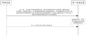
- Step 501 The network device sends DCI to the first terminal device.
- the DCI includes time domain resource information, where the time domain resource information is used to determine the time domain resource, and the time domain resource is the time domain where the first data channel is located. Resource; frequency domain resource information, the frequency domain resource information is used to determine frequency domain resources, and the frequency domain resources are the frequency domain resources where the first data channel is located and the frequency domain resources where the second data channel is located; The second data channel is located in a time domain resource different from the time domain resource where the first data channel is located.
- the first terminal device receives the DCI, and determines the time domain resource and the frequency domain resource of the first data channel according to the DCI.
- Step 502 The first terminal device receives a signal located on the first data channel from the network device on the determined time domain resource and the frequency domain resource.
- the first terminal device mentioned in the above steps may be the terminal device 3 in FIG. 4, that is, the NR-light terminal device.
- the foregoing steps may occur during the initial access by the first terminal device to obtain the SIB.
- the first data channel may be the PDSCH carrying SIB, and the signal located on the first data channel is the SIB.
- the first terminal device In order to obtain the SIB, the first terminal device needs to determine the time domain resource and the frequency domain resource of the first data channel, so as to receive the SIB on a certain time-frequency resource and complete the initial access.
- the DCI sent by the network device to the first terminal in step 501 may provide time domain resource information for determining the time domain resource of the first data channel and frequency domain resource information for determining the frequency domain resource of the first data channel. That is, the first terminal device may determine the time domain resource and the frequency domain resource of the first data channel based on the DCI received in step 501.
- the frequency domain resource determined by the frequency domain resource information is not only the frequency domain resource where the first data channel is located, but also another data channel, that is, the frequency domain resource where the second data channel is located.
- the second data channel can also be a PDSCH carrying SIB, but the first data channel is used for communication between the first terminal device and the network device, and the second data channel is used for another terminal device. That is, the second terminal device communicates with the network device, that is, the SIB that the first terminal device needs to acquire is located in the first data channel, and the SIB that the second terminal device needs to acquire is located in the second data channel.
- the first terminal device and the second terminal device may be different types of terminal devices.
- the first terminal device is an NR-light terminal device
- the second terminal device is a normal terminal device.
- the second data channel can be indicated through an existing field in the DCI. It can be seen from the above that the frequency domain resource information used to indicate the frequency domain resource of the first data channel is multiplexed with the frequency domain resource information of the second terminal device.
- the frequency domain resource information is the information of the existing frequency domain resource allocation field in Table 1 above.
- the time domain resource information specifically includes the following information:
- Time domain offset information which can be represented by the time domain offset value K0'.
- a time unit is the time unit where the first data channel is located. When K0' is greater than 0, the time unit of DCI is different from the first time unit;
- the time domain start position information can be represented by the time domain start symbol index value S'.
- the first terminal device can determine the first position according to S', and the first position is the first data channel at the first time.
- the time domain starting position of the unit, S' is an integer greater than or equal to 0;
- Duration information which can be represented by the number of occupied symbols L'
- the first terminal can determine the first duration according to L', and the first duration is the duration of the first data channel occupied by the first time unit, L 'Is an integer greater than or equal to 0.
- K0', S'and L' may be information independent of the time domain resource allocation field in the existing Table 1, or information in a newly added field.
- the newly added field is located in the reserved bit field in Table 1.
- K0', S'and L' can only be read by the first terminal device. If a second terminal device of a type different from the first terminal device also receives the DCI, the second terminal device will not read the information in the reserved bit field, that is, it cannot obtain K0', S', and L'.
- the first terminal device and the network device may pre-appoint a new table, and part or all of the content is the same as Table 2, for example, Table 3 below:
- the table contains at least row index and corresponding K0', S'and L'.
- the time domain resource information may be A bits located in the DCI reserved bit field, and the A bits may correspond to a row index (A represents an integer value).
- the specific position of the demodulation reference signal DMRS in the first data channel in the first time unit may be the same as the specific position of the DMRS in the second data channel in the second time unit by default.
- each row index in the table can correspond to at least one DMRS in the second time unit.
- the second terminal device is an ordinary terminal device.
- the channel and the second data channel are located in different time units (for example, located in different slots), that is, each of the first data channel and the second data channel can have sufficient time domain resources to carry signals.
- the first data channel since it is not in the same time unit as the PDCCH carrying DCI, the first data channel can occupy more time domain resources, that is, the amount of information carried by the signal will be larger. .
- the first position is also the time domain start position of the second time unit where the second data channel is located
- the first time length is also the time length occupied by the second time unit where the second data channel is located.
- the second time unit is the time unit where the second data channel is located.
- the frequency domain resource information that determines the frequency domain resource of the first data channel is multiplexed with the frequency domain resource information of the second terminal device, but also the part of the time domain resource information that determines the time domain resource of the first data channel is multiplexed. Part of the time domain resource information of the second terminal device is used, thereby further reducing the overhead of DCI signaling.
- K0' is new information located in the reserved bit field.
- the first terminal device can read K0', and the second terminal device of a different type from the first terminal device will not be able to read K0'.
- the B bits in the reserved bit field are used to indicate a K0' (B is an integer value), and the first terminal device can determine the first time unit in which the first data channel is located through K0'.
- the 4 possible K0's can also pass through the first terminal device and the network device It is agreed in advance or determined in the manner agreed in the agreement.
- the time domain resource that can be pre-appointed by the first terminal device and the network device can be used as The time domain resource of the first data channel. This can save system overhead to the utmost extent.
- the technical solution in the first embodiment is implemented on the basis that the first data channel is located in the same BWP as the DCI and the second data channel by default.
- the first data channel may also be located in a BWP different from the DCI and the second data channel, that is, at this time, the first data channel is located in the first BWP, and the DCI and the second data channel are located in the second BWP.
- the second embodiment of the present application provides another communication method for this situation, which is used to realize that the same DCI indicates the data channels of two different types of terminal devices, which ensures the forward compatibility.
- the first data channel of the first terminal device is located in a second BWP that is different from the second data channel of the second terminal device, that is, the first terminal device and the second terminal device complete the remaining BWP on different BWPs.
- the initial access process and random access process reduce the number of terminal devices that perform random access on the same BWP, thereby effectively reducing the collision probability of random access on the same BWP.
- the network device wants to page the terminal device communicating on the second BWP, then the first terminal device will not receive unnecessary paging. Paging messages, which makes paging more targeted and reduces the overhead of the entire system.
- FIG. 7 a schematic diagram of a communication method provided in Embodiment 2 of this application specifically includes the following steps.
- Step 701 A network device sends a DCI to a first terminal device on a second BWP, where the DCI includes BWP information, and the BWP information is used to determine a first BWP, and the first data channel is located in the first BWP.
- the first terminal device receives the DCI on the second BWP, and determines the first BWP and the first data channel according to the BWP information included in the DCI.
- Step 702 The first terminal device receives a signal located on the first data channel from the network device on the determined first BWP.
- the first terminal device can obtain the BWP information included in the DCI, thereby determining the location of the first BWP, and from the first BWP on the first BWP.
- the data channel gets the signal. For example, if the signal is SIB, the first terminal device can complete the initial access.
- the BWP information may include any of the following information:
- the first terminal device may determine the frequency domain interval between the second BWP and the first BWP according to the BWP offset information, for example, the frequency domain start position of the second BWP and the frequency domain start position of the first BWP.
- the frequency domain interval or the frequency domain interval between the end position of the frequency domain of the second BWP and the end position of the frequency domain of the first BWP.
- the frequency domain interval can be represented by a frequency domain offset value F, where F is greater than or equal to zero.
- the first terminal device may determine the bandwidth occupied by the first BWP according to the first BWP bandwidth information, for example, expressed by the number of RBs available for the occupied bandwidth L".
- the first terminal device may determine the frequency of the first BWP according to the first BWP start position information.
- the start position of the domain for example, is represented by the frequency domain start RB index value S".
- the BWP information may be located in a newly added field of the DCI, for example, it may be represented by one or more bits in the reserved bit field mentioned above.
- the BWP information may correspond to C bits (C is an integer value).
- C is an integer value
- C bits can correspond to a frequency domain offset value F, for example, C bits directly indicate to a F, or C bits to indicate a row index, and the row index is used to search for a predefined The corresponding F is obtained on a form of.
- F frequency domain offset value
- C bits can correspond to one F and one L".
- C1 bits of C bits correspond to one F
- F is the frequency domain start position of the second BWP and the first BWP
- the first terminal device determines the frequency-domain start position of the first BWP according to F. On the basis of the frequency-domain start position, superimpose L" backward, which is the first The location of BWP.
- C bits can correspond to an S" and an L".
- C3 bits in C bits correspond to one S
- the first terminal device can directly determine the position of the first BWP without relying on the position information of the second BWP, that is, superimpose L" backward on the basis of S", which is the position of the first BWP.
- the bandwidth of the first BWP can be configured according to actual conditions, which improves the flexibility of the system.
- the first BWP information that can be pre-appointed by the first terminal device and the network device may be used to determine the first BWP.
- the first terminal device also needs to determine the specific time domain resources and frequency domain resources of the first data channel on the first BWP.
- the specific method for determining time domain resources and frequency domain resources is the method for determining the time domain resources and frequency domain resources of the first data channel in the first embodiment.
- the first embodiment that is, At this time, the first embodiment and the second embodiment can be combined, which will not be repeated here.
- the newly added field corresponding to the BWP information and the newly added field corresponding to the time domain resource information can be converted into a unified indication of the same newly added field, or may still be separate different newly added fields.
- the first terminal device can reuse the information of the frequency domain resource allocation and time domain resource allocation fields in the existing Table 1, that is, determine the time-frequency resource of the second data channel in the second BWP as The time-frequency resource of the first data channel in the first BWP.
- distinguishing operations can be performed according to the following specific conditions:
- the shaded area is the frequency domain resource of the second data channel in the second BWP obtained according to the existing frequency domain resource allocation field.
- the first data channel is a frequency domain resource in the first BWP.
- the frequency domain resources determined by the frequency domain allocation field partially exceed the first BWP.
- the range of a BWP is shown in Figure 9(d). It can be considered that the start position of the frequency domain resource determined by the frequency domain allocation field is the start position of the first BWP, and the length of the frequency domain resource is still determined by the frequency domain allocation field. length.
- each parameter for determining the position of the first channel can also be individually indicated. This method does not have any restriction on the position of the first data channel, which improves the flexibility of the system.
- the third embodiment of the present application proposes a communication method as shown in FIG. 10, which specifically includes the following steps.
- Step 1001 The network device sends DCI to a first terminal device on a second BWP, where the DCI includes first information, and the first information is used to determine the first BWP where the first data channel is located and the first data The channel is the time-frequency resource of the first BWP.
- the first terminal device receives the DCI on the second BWP, and determines the first BWP and the time-frequency resources of the first data channel in the first BWP according to the DCI.
- Step 1002 The first terminal device receives a signal from the network device located on the first data channel on the determined first BWP.
- the first information includes: BWP information, time domain resource information, and frequency domain resource information.
- the time domain resource information may further include: time domain offset information, time domain start position information, and duration information.
- the above information is all indicated through newly added fields.
- the first terminal device and the network device may pre-appoint a form, as shown in Table 4:
- the frequency domain resource information in Table 4 is represented as RIV'.
- the frequency domain resource of the first data channel can be determined by referring to the existing way of determining frequency domain resources based on frequency domain resource allocation, or using a similar way.
- the first information may include a field of D bits, and the field of D bits corresponds to a row index, and the first terminal device can obtain K0", L", and S corresponding to the row index by querying Table 3. ", K0', RIV', S', and L'.
- the first BWP can be determined according to F, L", S", the frequency domain resource of the first data channel can be determined according to RIV', and the frequency domain resources of the first data channel can be determined according to K0', S' And L'determine the time domain resource of the first data channel, so that the signal from the network device and located in the first data channel can be received on the determined first BWP.
- the first information may be located in D bits in the reserved bits field of DCI.
- the first data channel and the second data channel are not only located in the same BWP, but the first data channel and the second data channel are also located in the same time unit.
- the fourth embodiment of the present application provides the following four different solutions:
- the first terminal device defaults all remaining time-frequency resources in the first time unit as the time-frequency resources of the first data channel. At this time, there is no need to add any field to the DCI, which is consistent with the default representation of A bits or B bits in the first embodiment, but has the same A bits or B bits in the first embodiment.
- the different meanings of the default are different schemes.
- the network device sends DCI to the first terminal device, the information in the DCI indicates the time-frequency resource of the second data channel of the second terminal device, and the second data channel is located in the first time-frequency resource in the first time unit;
- the first terminal device receives the DCI, and according to the information in the DCI, receives the signal of the first data channel of the first terminal on the second time-frequency resource of the first time unit.
- the second time-frequency resource is the remaining part of the first time unit excluding the first time-frequency resource.
- the first terminal device defaults that the first data channel and the second data channel have the same time domain resources, that is, the first terminal device can multiplex the DCI time domain resource allocation to determine the first data channel Time domain resources.
- a new field needs to be added in the DCI to determine the frequency domain resource of the first data channel.
- the newly added field corresponds to an RIV', and a section of frequency domain resources can be correspondingly determined. If part of the frequency domain resource determined by the RIV' overlaps with the second data channel, the first terminal device will skip this part of the frequency domain resource, that is, it will not try to receive on the frequency domain resource overlapping with the second data channel Signal of the first data channel.
- the way of determining frequency domain resources according to RIV' can refer to the existing way of determining frequency domain resources according to frequency domain resource allocation, or use a similar way.
- the network device sends DCI to the first terminal device, where the DCI includes time domain resource information, and the time domain resource information is used to determine a first time domain resource, and the first time domain resource is the first The time domain resource where the data channel is located, and the time domain resource where the second data channel is located; frequency domain resource information, where the frequency domain resource information is used to determine a first frequency domain resource, and the first frequency domain resource is the first frequency domain resource.
- a frequency domain resource where a data channel is located; the second data channel and the first data channel are located in the same time unit, and the frequency domain resources of the first data channel and the frequency domain resources of the second data channel are different overlapping.
- the first terminal device receives the DCI, and according to the information in the DCI, receives the signal from the network device and the first data channel on the first time domain resource and the first frequency domain resource.
- the first terminal device defaults that the first data channel and the second data channel have the same frequency domain resources, that is, the first terminal device can reuse the frequency domain resource allocation of DCI to determine the first data channel
- a new field is required in the DCI to determine the time domain resource of the first data channel.
- the newly added field corresponds to an S'and an L'. If part of the time domain resources determined by S'and L'overlaps with the second data channel, the first terminal device will skip this part of the time domain resources, that is, it will not try to overlap with the second data channel in the time domain.
- the signal of the first data channel is received on the resource.
- the network device sends DCI to the first terminal device, where the DCI includes frequency domain resource information, and the frequency domain resource information is used to determine a first frequency domain resource, and the first frequency domain resource is the first The frequency domain resource where the data channel is located, and the frequency domain resource where the second data channel is located; time domain resource information, where the time domain resource information is used to determine a first time domain resource, and the first time domain resource is the first time domain resource.
- a time domain resource where a data channel is located; the second data channel and the first data channel are located in the same time unit, and the frequency domain resources of the first data channel and the time domain resources of the second data channel are different overlapping.
- the first terminal device receives the DCI, and according to the information in the DCI, receives the signal from the network device and the first data channel on the first time domain resource and the first frequency domain resource.
- new fields are needed in DCI to determine the time domain resources and frequency domain resources of the first data channel, that is, the frequency domain resource allocation fields and time domain resources in the existing DCI are not reused Assign field.
- the newly added field may correspond to one RIV', one S'and one L'
- the frequency domain resource of the first data channel is determined according to RIV'
- the time domain resource of the first data channel is determined according to S'and L'
- Their determination methods have been given in the foregoing. If part of the frequency domain resource determined by the RIV' value overlaps with the second data channel, the first terminal device will skip this part of the frequency domain resource, that is, it will not try to use the frequency domain resource that overlaps with the second data channel.
- the first terminal device will skip this part of the time domain resources, that is, it will not try to overlap with the second data channel in the time domain.
- the signal of the first data channel is received on the resource.
- the network device sends DCI to the first terminal device, where the DCI includes frequency domain resource information, and the frequency domain resource information is used to determine a first frequency domain resource, and the first frequency domain resource is the first frequency domain resource.
- the second data channel and the first data channel are located in the same time unit, and the time-frequency resources of the first data channel and the time-frequency domain resources of the second data channel do not overlap.
- the first terminal device receives the DCI, and according to the information in the DCI, receives the signal from the network device and the first data channel on the first time domain resource and the first frequency domain resource.
- the newly added fields described in the above schemes 2 to 4 may be located in the reserved bit field in the DCI.
- the first data channel and the second data channel may be located in the same time unit or in different time units in the time domain.
- the fifth embodiment of this application proposes a mechanism based on the foregoing embodiments for the first terminal device to determine whether the first data channel and the second data channel are located in the same time unit .
- the confirmation information may be included in a newly added field, such as a reserved field located in the DCI, which is used to determine whether the first data channel and the second data channel are located in the same time unit.
- the newly added field includes 1 bit. When the value of this bit is "1", the first terminal device determines that the first data channel and the second data channel are located in the same time unit; when the value of this bit is "0" , The first terminal device determines that the first data channel and the second data channel are located in different time units.
- the frequency domain resource allocation field and/or the time domain allocation field in the DCI shown in the existing Table 1 can be used to determine whether the first data channel and the second data channel are located in the same time unit. Specifically, it is further divided into the following possibilities:
- the time domain resource allocation field may determine the S and L values of the second data channel. For example, when S and/or L is greater than (or less than) a certain threshold, the first terminal device may determine that the first data channel and the second data channel are located in the same time unit, otherwise, the first terminal device determines the first data channel It is located in a different time unit from the second data channel. As another example, when S and/or L are odd numbers (or even numbers), the first terminal device determines that the first data channel and the second data channel are located in the same time unit; otherwise, the first terminal device determines that the first data channel and the first data channel are in the same time unit. The two data channels are located in different time units.
- the frequency domain resource allocation field may determine the S" and L" values of the second data channel. For example, when S" and/or L" is greater than (or less than) a certain threshold, the first terminal device can determine that the first data channel and the second data channel are located in the same time unit, otherwise, the first terminal device determines the first data The channel and the second data channel are located in different time units. For another example, when S" and/or L" are odd (or even) numbers, the first terminal device determines that the first data channel and the second data channel are located in the same time unit, otherwise, the first terminal device determines the first data channel It is located in a different time unit from the second data channel.
- the frequency domain resource allocation field and the time domain resource allocation field are combined to determine, and the total amount of time-frequency resources occupied by the second data channel can be determined according to the frequency domain resource allocation field and the time domain resource allocation field. For example, when the total amount of time-frequency resources occupied by the second data channel is greater than (or less than) a certain threshold, the first terminal device may determine that the first data channel and the second data channel are located in the same time unit, otherwise, the first terminal device It is determined that the first data channel and the second data channel are located in different time units.
- the first terminal device may determine that the first data channel and the second data channel are located in the same time unit, otherwise, the first terminal device It is determined that the first data channel and the second data channel are located in different time units.
- Embodiments 1 to 5 of the present application can also be extended to the paging procedure.
- the terminal device can obtain the time-frequency resource of the data channel where the paging message is located by receiving the DCI scrambled by the paging-radio network temporary identifier (P-RNTI) sent by the network device.
- P-RNTI paging-radio network temporary identifier
- the specific fields included in the DCI scrambled by the P-RNTI are similar to the DCI scrambled by the SI-RNTI, and at least include a frequency domain resource allocation field, a time domain allocation field, and a reserved bit field.
- the indication mode of the time domain resource and frequency domain resource of the data channel of the DCI scheduling scrambled by P-RNTI and the indication mode of the time domain resource and frequency domain resource of the data channel of the DCI scheduling scrambled by the SI-RNTI are consistent. You can refer to the descriptions in the relevant paragraphs, so I won’t repeat them here.
- the embodiments of the present application not only expect that the DCI scrambled by the P-RNTI sent by the network device can indicate the time-frequency resource of the data channel where the paging message is located, but also expect the P-RNTI scrambled
- the DCI can also indicate the time-frequency resource of the data channel where the network device sends downlink small data to the terminal device. In this way, the overhead of DCI in the system is reduced as much as possible.
- the sixth embodiment of the present application extends the application scenarios of the first to fifth embodiments, that is, extends from the application to the initial access process to the paging process.
- the first data channel referred to in the first to fifth embodiments may be the PDSCH carrying the downlink small data in the sixth embodiment
- the second data channel may be the PDSCH carrying the paging message and the PDSCH located in the first data channel.
- the signal can be downlink small data.
- the terminal device that receives the DCI scrambled by the P-RNTI can be the first terminal device or the second terminal device in Embodiments 1 to 5, which can be understood as a certain type of terminal device, which can be an NR-light terminal.
- the equipment, etc. is a new type of terminal device that is different from the existing ordinary terminal device, and may also be an existing ordinary terminal device. This embodiment is a further improvement to its performance.
- the terminal device in this embodiment of the application will receive signals on the first data channel, that is, downlink small data, and will also receive signals on the second data channel. , which is a paging message.
- the DCI scrambled by the P-RNTI indicates the time-frequency resource where the first data channel is located.
- the time domain resource information in step 501 specifically includes K0', S', and L'.
- K0', S'and L' can be information independent of the time domain resource allocation field in the existing Table 1, or information in newly added fields.
- the newly added field is located in the reserved bit field of DCI scrambled by P-RNTI.
- the terminal device in the sixth embodiment of the present application is configured to read all DCI fields including the reserved bit field. In this way, the terminal device can not only obtain K0, S, and L, but also obtain K0', S', and L'in the manner described in the first embodiment.
- the terminal device can be based on the determined frequency domain resource And the determined time-domain resource information, receive the received downlink small data located on the first data channel, and at the same time receive the paging message located on the second data channel according to the prior art.
- the scene in the sixth embodiment can be introduced similarly and without obstacles, which is understandable to those skilled in the art.
- the embodiment of the present application can effectively reduce system overhead and improve resource utilization. It can also solve the problem of insufficient channel capacity for carrying paging messages.
- the communication method provided in the embodiments of the present application is introduced from the perspective of a terminal device as an execution subject.
- the terminal device may include a hardware structure and/or a software module, and realize the above functions in the form of a hardware structure, a software module, or a hardware structure plus a software module. Whether a certain function among the above-mentioned functions is executed by a hardware structure, a software module, or a hardware structure plus a software module depends on the specific application and design constraint conditions of the technical solution.
- an embodiment of the present application further provides an apparatus 1300, and the apparatus 1300 includes a transceiver module 1301 and a processing module 1302.
- the apparatus 1300 is used to implement the functions of the terminal devices in the first to sixth embodiments above.
- the device 1300 may be the first terminal device, or may be a device located in the first terminal device.
- the device may be a chip system.
- the chip system can be composed of chips, or it can include chips and other discrete devices.
- the transceiver module 1301 is used to receive information from a network device or used to send information to the network device; the processing module 1302 is used to perform other functions except the information transceiver function.
- Information in this application may include data, signaling, reference signals, and so on.
- the processing module 1302 is configured to control the transceiver module 1301 to receive the downlink control information DCI from the network device, and the DCI includes: time domain resource information.
- Time domain resource information is used to determine a time domain resource, where the time domain resource is a time domain resource where the first data channel is located; frequency domain resource information, where the frequency domain resource information is used to determine a frequency domain resource, the frequency domain resource Is the frequency domain resource where the first data channel is located and the frequency domain resource where the second data channel is located; the second data channel is located in a time domain resource different from the time domain resource where the first data channel is located.
- the processing module 1302 may determine the frequency domain resource and the time domain resource where the first data channel is located based on the received DCI.
- the processing module 1302 is further configured to control the transceiver module 1301 to receive a signal from the network device on the first data channel on the determined time domain resource and the frequency domain resource.
- the first data channel is used for the first terminal device to communicate with the network device; the second data channel is used for the second terminal device to communicate with the network device.
- the apparatus 1300 is used to implement the function of the network device in the foregoing method.
- the device 1300 may be a network device or a device located in the network device.
- the device may be a chip system.
- the chip system can be composed of chips, or it can include chips and other discrete devices.
- the transceiver module 1301 is used to receive information from a network device or used to send information to the network device; the processing module 1302 is used to perform other functions except the information transceiver function.
- the processing module 1302 is configured to control the transceiver module 1301 to send downlink control information DCI to the first terminal device.
- the DCI includes: time domain resource information. Domain resource information is used to determine a time domain resource, where the time domain resource is a time domain resource where the first data channel is located; and frequency domain resource information, where the frequency domain resource information is used to determine a frequency domain resource, where the frequency domain resource is The frequency domain resource where the first data channel is located and the frequency domain resource where the second data channel is located; the second data channel is located in a time domain resource different from the time domain resource where the first data channel is located.
- the processing module 1302 is further configured to control the transceiver module 1301 to send a signal located on the first data channel to the first terminal device on the time domain resource and the frequency domain resource.
- the first data channel is used for the network device to communicate with the first terminal device; the second data channel is used for the network device to communicate with the second terminal device.
- the transceiver module 1301 and the processing module 1302 For the specific execution process of the transceiver module 1301 and the processing module 1302, please refer to the record in the first embodiment.
- the division of modules in the embodiments of the present application is illustrative, and is only a logical function division, and there may be other division methods in actual implementation.
- the functional modules in the various embodiments of the present application may be integrated in one processor, or may exist alone physically, or two or more modules may be integrated in one module.
- the above-mentioned integrated modules can be implemented in the form of hardware or software functional modules.
- the apparatus 1300 may also be used to implement the functions of the first terminal device and the network device in Embodiment 2 to Embodiment 6.
- a person skilled in the art combines the description of the above device embodiment and the process description in the second to the sixth embodiment, without creative work, can easily obtain the terminal equipment and the terminal equipment used to implement the second to the sixth embodiment.
- the device embodiments of the network equipment will not be repeated here.
- an embodiment of the present application further provides an apparatus 1400.
- the device 1400 includes one or more processors 1401.
- the device 1400 is used to implement the function of the first terminal device in the foregoing method.
- the device 1400 may be the first terminal device or a device applied to the first terminal device, such as a chip.
- the processor 1401 is configured to implement the functions of the terminal devices in the first to sixth embodiments. For details, please refer to the detailed description in the above-mentioned Embodiments 1 to 6, which will not be described here.
- the device 1400 is used to implement the function of the network device in the above method.
- the device 1400 may be a network device or a device applied to the network device, such as a chip.
- the apparatus 1400 has at least one processor 1401, which is configured to implement the functions of the network equipment in the first embodiment to the sixth embodiment.
- the apparatus 1400 may further include at least one memory 1402 for storing program instructions and/or data.
- the memory 1402 is coupled with the processor 1401.
- the coupling in the embodiments of the present application is an interval coupling or a communication connection between devices, units or modules, which can be electrical, mechanical or other forms, and is used for information exchange between devices, units or modules.
- the memory 1402 may also be located outside the apparatus 1400.
- the processor 1401 may operate in cooperation with the memory 1402.
- the processor 1401 may execute program instructions stored in the memory 1402. At least one of the at least one memory may be included in the processor.
- the processor may be a general-purpose processor, a digital signal processor, an application specific integrated circuit, a field programmable gate array or other programmable logic device, a discrete gate or transistor logic device, a discrete hardware component, which can implement or execute the disclosure in the embodiments of the present application
- the general-purpose processor may be a microprocessor or any conventional processor or the like. Combining the steps of the methods disclosed in the embodiments of the present application can be directly embodied as the hardware in the processor executes the steps of these methods, or the hardware and software modules in the processor are combined to execute the steps of these methods.
- the memory can be non-volatile memory, such as hard disk (HD) or solid-state drive (SSD), etc., or volatile memory, such as random-access memory (random-access memory).
- memory random-access memory
- the memory is any medium that can be used to carry or store program codes in the form of instructions or data structures and that can be accessed by a computer, but is not limited to this.
- the memory in the embodiments of the present application may also be a circuit or any other device capable of realizing a storage function for storing program instructions and/or data.
- the apparatus 1400 may further include a communication interface 1403 for communicating with other devices through a transmission medium, so that the apparatus 1400 can communicate with other devices.
- the communication interface 1403 may be a transceiver, a circuit, a bus, or other types of communication interfaces, and the other device may be a network device.
- the processor 1401 uses the communication interface 1403 to send and receive information, and is used to implement the methods in the first to sixth embodiments.
- the embodiment of the application does not limit the connection medium between the communication interface 1403, the processor 1401, and the memory 1402.
- it may be connected by a bus, and the bus may include at least one of an address bus, a data bus, and a control bus. .
- the ninth embodiment of the present application provides an electronic device.
- the electronic device is used to implement the function of the first terminal device in the foregoing method.
- the electronic device may be the first terminal device, or a device applied in the first terminal device, such as a chip.
- the electronic device provided in this embodiment is used to implement the functions of the first terminal device in the first to sixth embodiments above.
- Fig. 15 is a schematic diagram of a general structure of an electronic device.
- the first terminal device may be an NR-light terminal device.
- the manufacturing cost of NR-light terminal equipment is lower, and the communication bandwidth with network equipment is lower, and the power consumption is also lower.
- the NR-light terminal device may include some or all of the components of the electronic device 1500 as shown in FIG. 15.
- the electronic device 1500 in FIG. 15 will be described in detail below.
- the electronic device 1500 may include a processor 1510, an external memory interface 1520, an internal memory 1521, a universal serial bus (USB) interface 1530, a charging management module 1540, a power management module 1541, a battery 1542, antenna 1, antenna 2 , Mobile communication module 1550, wireless communication module 1560, audio module 1570, speaker 1570A, receiver 1570B, microphone 1570C, earphone jack 1570D, sensor module 1580, buttons 1590, motor 1591, indicator 1592, camera 1593, display 1594, and Subscriber identification module (subscriber identification module, SIM) card interface 1595, etc.
- SIM Subscriber identification module
- the sensor module 1580 may include pressure sensor 1580A, gyroscope sensor 1580B, air pressure sensor 1580C, magnetic sensor 1580D, acceleration sensor 1580E, distance sensor 1580F, proximity light sensor 1580G, fingerprint sensor 1580H, temperature sensor 1580J, touch sensor 1580K, ambient light Sensor 1580L, bone conduction sensor 1580M, etc.
- the structure illustrated in the embodiment of the present application does not constitute a specific limitation on the electronic device 1500.
- the electronic device 1500 may include more or fewer components than shown, or combine certain components, or split certain components, or arrange different components.
- the illustrated components can be implemented in hardware, software, or a combination of software and hardware.
- the processor 1510 may include one or more processing units.
- the processor 1510 may include an application processor (AP), a modem processor, a graphics processing unit (GPU), and an image signal processor. (image signal processor, ISP), controller, memory, video codec, digital signal processor (digital signal processor, DSP), baseband processor, and/or neural-network processing unit (NPU) Wait.
- AP application processor
- modem processor modem processor
- GPU graphics processing unit
- image signal processor image signal processor
- ISP image signal processor
- controller memory
- video codec digital signal processor
- DSP digital signal processor
- NPU neural-network processing unit
- the different processing units may be independent devices or integrated in one or more processors.
- the controller can generate operation control signals according to the instruction operation code and timing signals to complete the control of fetching instructions and executing instructions.
- a memory may also be provided in the processor 1510 to store instructions and data.
- the memory in the processor 1510 is a cache memory.
- the memory can store instructions or data that have just been used or recycled by the processor 1510. If the processor 1510 needs to use the instruction or data again, it can be directly called from the memory. Repeated accesses are avoided, the waiting time of the processor 1510 is reduced, and the efficiency of the system is improved.
- the processor 1510 may include one or more interfaces.
- the interface may include an integrated circuit (inter-integrated circuit, I2C) interface, an integrated circuit built-in audio (inter-integrated circuit sound, I2S) interface, a pulse code modulation (pulse code modulation, PCM) interface, and a universal asynchronous transmitter/receiver (universal asynchronous) interface.
- I2C integrated circuit
- I2S integrated circuit built-in audio
- PCM pulse code modulation
- PCM pulse code modulation
- UART universal asynchronous transmitter/receiver
- MIPI mobile industry processor interface
- GPIO general-purpose input/output
- SIM subscriber identity module
- USB Universal Serial Bus
- the I2C interface is a bidirectional synchronous serial bus, including a serial data line (SDA) and a serial clock line (SCL).
- the processor 110 may include multiple sets of I2C buses.
- the processor 1510 may couple the touch sensor 1580K, charger, flash, camera 1593, etc., through different I2C bus interfaces, respectively.
- the processor 1510 may couple the touch sensor 1580K through an I2C interface, so that the processor 1510 and the touch sensor 1580K communicate through an I2C bus interface to implement the touch function of the electronic device 1500.
- the I2S interface can be used for audio communication.
- the processor 1510 may include multiple sets of I2S buses.
- the processor 1510 may be coupled with the audio module 1570 through an I2S bus to implement communication between the processor 1510 and the audio module 1570.
- the audio module 1570 may transmit audio signals to the wireless communication module 1560 through the I2S interface, so as to realize the function of answering calls through the Bluetooth headset.
- the PCM interface can also be used for audio communication to sample, quantize and encode analog signals.
- the audio module 1570 and the wireless communication module 1560 may be coupled through a PCM bus interface.
- the audio module 1570 may also transmit audio signals to the wireless communication module 1560 through the PCM interface, so as to realize the function of answering calls through the Bluetooth headset. Both the I2S interface and the PCM interface can be used for audio communication.
- the UART interface is a universal serial data bus used for asynchronous communication.
- the bus can be a two-way communication bus. It converts the data to be transmitted between serial communication and parallel communication.
- the UART interface is generally used to connect the processor 1510 and the wireless communication module 1560.
- the processor 1510 communicates with the Bluetooth module in the wireless communication module 1560 through the UART interface to realize the Bluetooth function.
- the audio module 1570 may transmit audio signals to the wireless communication module 1560 through the UART interface, so as to realize the function of playing music through the Bluetooth headset.
- the MIPI interface can be used to connect the processor 1510 with the display 1594, camera 1593 and other peripheral devices.
- the MIPI interface includes a camera serial interface (camera serial interface, CSI), a display serial interface (display serial interface, DSI), and so on.
- the processor 1510 and the camera 1593 communicate through a CSI interface to implement the shooting function of the electronic device 1500.
- the processor 1510 and the display screen 1594 communicate through the DSI interface to realize the display function of the electronic device 1500.
- the GPIO interface can be configured through software.
- the GPIO interface can be configured as a control signal or as a data signal.
- the GPIO interface may be used to connect the processor 1510 with the camera 1593, the display screen 1594, the wireless communication module 1560, the audio module 1570, the sensor module 1580, and so on.
- the GPIO interface can also be configured as an I2C interface, I2S interface, UART interface, MIPI interface, etc.
- the USB interface 1530 is an interface that complies with the USB standard specifications, and specifically can be a Mini USB interface, a Micro USB interface, a USB Type C interface, and so on.
- the USB interface 1530 can be used to connect a charger to charge the electronic device 1500, and can also be used to transfer data between the electronic device 1500 and peripheral devices. It can also be used to connect earphones and play audio through earphones. This interface can also be used to connect other electronic devices, such as AR devices.
- the interface connection relationship between the modules illustrated in the embodiment of the present application is merely a schematic description, and does not constitute a structural limitation of the electronic device 1500.
- the electronic device 1500 may also adopt different interface connection modes in the foregoing embodiments, or a combination of multiple interface connection modes.
- the charging management module 1540 is used to receive charging input from the charger.
- the charger can be a wireless charger or a wired charger.
- the charging management module 1540 may receive the charging input of the wired charger through the USB interface 1530.
- the charging management module 1540 may receive the wireless charging input through the wireless charging coil of the electronic device 1500. While the charging management module 1540 charges the battery 1542, it can also supply power to the electronic device through the power management module 1541.
- the power management module 1541 is used to connect the battery 1542, the charging management module 1540 and the processor 1510.
- the power management module 1541 receives input from the battery 1542 and/or the charge management module 1540, and supplies power to the processor 1510, internal memory 1521, external memory, display 1594, camera 1593, and wireless communication module 1560.
- the power management module 1541 can also be used to monitor battery capacity, battery cycle times, battery health status (leakage, impedance) and other parameters.
- the power management module 1541 may also be provided in the processor 1510.
- the power management module 1541 and the charging management module 1540 may also be provided in the same device.
- the wireless communication function of the electronic device 1500 can be implemented by the antenna 1, the antenna 2, the mobile communication module 1550, the wireless communication module 1560, the modem processor, and the baseband processor.
- the antenna 1 and the antenna 2 are used to transmit and receive electromagnetic wave signals.
- Each antenna in the electronic device 1500 can be used to cover a single or multiple communication frequency bands. Different antennas can also be reused to improve antenna utilization.
- antenna 1 can be multiplexed as a diversity antenna of a wireless local area network.
- the antenna can be used in combination with a tuning switch.
- the mobile communication module 1550 can provide a wireless communication solution including 2G/3G/4G/5G and the like applied to the electronic device 100.
- the mobile communication module 1550 may include at least one filter, switch, power amplifier, low noise amplifier (LNA), etc.
- the mobile communication module 1550 can receive electromagnetic waves by the antenna 1, and perform processing such as filtering, amplifying and transmitting the received electromagnetic waves to the modem processor for demodulation.
- the mobile communication module 1550 can also amplify the signal modulated by the modem processor, and convert it into electromagnetic wave radiation via the antenna 1.
- at least part of the functional modules of the mobile communication module 1550 may be provided in the processor 110.
- at least part of the functional modules of the mobile communication module 1550 and at least part of the modules of the processor 1510 may be provided in the same device.
- the modem processor may include a modulator and a demodulator.
- the modulator is used to modulate the low frequency baseband signal to be sent into a medium and high frequency signal.
- the demodulator is used to demodulate the received electromagnetic wave signal into a low-frequency baseband signal.
- the demodulator then transmits the demodulated low-frequency baseband signal to the baseband processor for processing.
- the application processor outputs a sound signal through an audio device (not limited to a speaker 1570A, a receiver 1570B, etc.), or displays an image or video through a display screen 1594.
- the modem processor may be an independent device.
- the modem processor may be independent of the processor 1510 and be provided in the same device as the mobile communication module 1550 or other functional modules.
- the wireless communication module 1560 can provide applications on the electronic device 1500 including wireless local area networks (WLAN) (such as wireless fidelity (Wi-Fi) networks), bluetooth (BT), and global navigation satellites.
- WLAN wireless local area networks
- BT wireless fidelity
- GNSS global navigation satellite system
- FM frequency modulation
- NFC near field communication technology
- infrared technology infrared, IR
- the wireless communication module 1560 may be one or more devices integrating at least one communication processing module.
- the wireless communication module 1560 receives electromagnetic waves via the antenna 2, frequency modulates and filters the electromagnetic wave signals, and sends the processed signals to the processor 1510.
- the wireless communication module 1560 may also receive the signal to be sent from the processor 1510, perform frequency modulation, amplify, and convert it into electromagnetic waves to radiate through the antenna 2.
- the antenna 1 of the electronic device 1500 is coupled with the mobile communication module 1550, and the antenna 2 is coupled with the wireless communication module 1560, so that the electronic device 1500 can communicate with the network and other devices through wireless communication technology.
- the wireless communication technology may include global system for mobile communications (GSM), general packet radio service (GPRS), code division multiple access (CDMA), broadband Code division multiple access (wideband code division multiple access, WCDMA), time-division code division multiple access (TD-SCDMA), long term evolution (LTE), BT, GNSS, WLAN, NFC , FM, and/or IR technology, etc.
- the GNSS may include global positioning system (GPS), global navigation satellite system (GLONASS), Beidou navigation satellite system (BDS), quasi-zenith satellite system (quasi -zenith satellite system, QZSS) and/or satellite-based augmentation systems (SBAS).
- GPS global positioning system
- GLONASS global navigation satellite system
- BDS Beidou navigation satellite system
- QZSS quasi-zenith satellite system
- SBAS satellite-based augmentation systems
- the electronic device 1500 implements a display function through a GPU, a display screen 1594, and an application processor.
- the GPU is a microprocessor for image processing, connected to the display 1594 and the application processor.
- the GPU is used to perform mathematical and geometric calculations and is used for graphics rendering.
- the processor 1510 may include one or more GPUs that execute program instructions to generate or change display information.
- the display screen 1594 is used to display images, videos, etc.
- the display screen 1594 includes a display panel.
- the display panel can use liquid crystal display (LCD), organic light-emitting diode (OLED), active matrix organic light-emitting diode or active-matrix organic light-emitting diode (active-matrix organic light-emitting diode).
- LCD liquid crystal display
- OLED organic light-emitting diode
- active-matrix organic light-emitting diode active-matrix organic light-emitting diode
- AMOLED flexible light-emitting diode (FLED), Miniled, MicroLed, Micro-oLed, quantum dot light-emitting diode (QLED), etc.
- the electronic device 1500 may include one or N display screens 1594, and N is a positive integer greater than one.
- the electronic device 1500 can realize a shooting function through an ISP, a camera 1593, a video codec, a GPU, a display screen 1594, and an application processor.
- the ISP is used to process the data fed back from the camera 1593. For example, when taking a picture, the shutter is opened, the light is transmitted to the photosensitive element of the camera through the lens, the light signal is converted into an electrical signal, and the photosensitive element of the camera transmits the electrical signal to the ISP for processing and is converted into an image visible to the naked eye.
- ISP can also optimize the image noise, brightness, and skin color. ISP can also optimize the exposure, color temperature and other parameters of the shooting scene.
- the ISP may be provided in the camera 1593.
- the camera 1593 is used to capture still images or videos.
- the object generates an optical image through the lens and is projected to the photosensitive element.
- the photosensitive element may be a charge coupled device (CCD) or a complementary metal-oxide-semiconductor (CMOS) phototransistor.
- CMOS complementary metal-oxide-semiconductor
- the photosensitive element converts the optical signal into an electrical signal, and then transfers the electrical signal to the ISP to convert it into a digital image signal.
- ISP outputs digital image signals to DSP for processing.
- DSP converts digital image signals into standard RGB, YUV and other formats of image signals.
- the electronic device 1500 may include 1 or N cameras 1593, and N is a positive integer greater than 1.
- Digital signal processors are used to process digital signals. In addition to digital image signals, they can also process other digital signals. For example, when the electronic device 1500 selects a frequency point, the digital signal processor is used to perform Fourier transform on the energy of the frequency point.
- Video codecs are used to compress or decompress digital video.
- the electronic device 1500 may support one or more video codecs.
- the electronic device 1500 can play or record videos in multiple encoding formats, for example: moving picture experts group (MPEG) 1, MPEG2, MPEG3, MPEG4, and so on.
- MPEG moving picture experts group
- NPU is a neural-network (NN) computing processor.
- NN neural-network
- applications such as intelligent cognition of the electronic device 1500 can be realized, such as image recognition, face recognition, voice recognition, text understanding, and so on.
- the external memory interface 1520 may be used to connect an external memory card, such as a Micro SD card, so as to expand the storage capacity of the electronic device 1500.
- the external memory card communicates with the processor 1510 through the external memory interface 1520 to realize the data storage function. For example, save music, video and other files in an external memory card.
- the internal memory 1521 may be used to store computer executable program code, where the executable program code includes instructions.
- the processor 1510 executes various functional applications and data processing of the electronic device 1500 by running instructions stored in the internal memory 1521.
- the internal memory 1521 may include a program storage area and a data storage area.
- the storage program area can store an operating system, an application program (such as a sound playback function, an image playback function, etc.) required by at least one function, and the like.
- the data storage area can store data (such as audio data, phone book, etc.) created during the use of the electronic device 1500.
- the internal memory 1521 may include a high-speed random access memory, and may also include a non-volatile memory, such as at least one magnetic disk storage device, a flash memory device, a universal flash storage (UFS), and the like.
- UFS universal flash storage
- the electronic device 1500 may implement audio functions through the audio module 1570, the speaker 1570A, the receiver 1570B, the microphone 1570C, the earphone interface 1570D, and the application processor. For example, music playback, recording, etc.
- the audio module 1570 is used to convert digital audio information into an analog audio signal for output, and is also used to convert an analog audio input into a digital audio signal.
- the audio module 1570 can also be used to encode and decode audio signals.
- the audio module 1570 may be provided in the processor 1510, or part of the functional modules of the audio module 1570 may be provided in the processor 1510.
- the speaker 1570A also called “speaker” is used to convert audio electrical signals into sound signals.
- the electronic device 1500 can listen to music through the speaker 1570A, or listen to a hands-free call.
- the receiver 1570B also called “earpiece” is used to convert audio electrical signals into sound signals.
- the electronic device 1500 answers a call or voice message, it can receive the voice by bringing the receiver 1570B close to the human ear.
- the microphone 1570C also called “microphone”, “microphone”, is used to convert sound signals into electrical signals.
- the user can make a sound by approaching the microphone 1570C through the human mouth, and input the sound signal into the microphone 1570C.
- the electronic device 1500 may be provided with at least one microphone 1570C. In other embodiments, the electronic device 1500 may be provided with two microphones 1570C, which can implement noise reduction functions in addition to collecting sound signals. In other embodiments, the electronic device 1500 may also be provided with three, four or more microphones 1570C to collect sound signals, reduce noise, identify sound sources, and realize directional recording functions.
- the earphone interface 1570D is used to connect wired earphones.
- the earphone interface 1570D may be a USB interface 1530, or a 3.5mm open mobile terminal platform (OMTP) standard interface, or a cellular telecommunications industry association of the USA (CTIA) standard interface.
- OMTP open mobile terminal platform
- CTIA cellular telecommunications industry association of the USA
- the pressure sensor 1580A is used to sense the pressure signal and can convert the pressure signal into an electrical signal.
- the pressure sensor 1580A may be provided on the display screen 1594. Pressure sensor 1580A
- the capacitive pressure sensor may include at least two parallel plates with conductive materials.
- the electronic device 1500 determines the intensity of the pressure according to the change in capacitance.
- the electronic device 1500 detects the intensity of the touch operation according to the pressure sensor 1580A.
- the electronic device 1500 may also calculate the touched position according to the detection signal of the pressure sensor 1580A.
- touch operations that act on the same touch position but have different touch operation strengths may correspond to different operation instructions.
- the gyroscope sensor 1580B may be used to determine the movement posture of the electronic device 1500.
- the angular velocity of the electronic device 1500 around three axes ie, x, y, and z axes
- the gyro sensor 1580B can be used for image stabilization.
- the gyroscope sensor 1580B detects the jitter angle of the electronic device 1500, calculates the distance that the lens module needs to compensate according to the angle, and allows the lens to counteract the jitter of the electronic device 1500 through reverse movement to achieve anti-shake.
- the gyro sensor 1580B can also be used for navigation and somatosensory game scenes.
- the air pressure sensor 1580C is used to measure air pressure.
- the electronic device 1500 calculates the altitude based on the air pressure value measured by the air pressure sensor 1580C to assist positioning and navigation.
- the magnetic sensor 1580D includes a Hall sensor.
- the electronic device 1500 may use the magnetic sensor 1580D to detect the opening and closing of the flip holster.
- the electronic device 1500 can detect the opening and closing of the flip according to the magnetic sensor 1580D.
- features such as automatic unlocking of the flip cover are set.
- the acceleration sensor 1580E can detect the magnitude of the acceleration of the electronic device 1500 in various directions (generally three axes). When the electronic device 1500 is stationary, the magnitude and direction of gravity can be detected. It can also be used to identify the posture of electronic devices, and apply to applications such as horizontal and vertical screen switching, pedometers, etc.
- the electronic device 1500 can measure the distance by infrared or laser. In some embodiments, when shooting a scene, the electronic device 1500 may use the distance sensor 1580F to measure the distance to achieve fast focusing.
- the proximity light sensor 1580G may include, for example, a light emitting diode (LED) and a light detector, such as a photodiode.
- the light emitting diode may be an infrared light emitting diode.
- the electronic device 1500 emits infrared light to the outside through the light emitting diode.
- the electronic device 1500 uses a photodiode to detect infrared reflected light from nearby objects. When sufficient reflected light is detected, it can be determined that there is an object near the electronic device 1500. When insufficient reflected light is detected, the electronic device 1500 can determine that there is no object near the electronic device 1500.
- the electronic device 1500 can use the proximity light sensor 1580G to detect that the user holds the electronic device 1500 close to the ear to talk, so as to automatically turn off the screen to save power.
- Proximity light sensor 1580G can also be used in leather case mode, pocket mode automatically unlocks and locks the screen.
- the ambient light sensor 1580L is used to sense the brightness of the ambient light.
- the electronic device 1500 can adaptively adjust the brightness of the display screen 1594 according to the perceived brightness of the ambient light.
- the ambient light sensor 1580L can also be used to automatically adjust the white balance when taking pictures.
- the ambient light sensor 1580L can also cooperate with the proximity light sensor 1580G to detect whether the electronic device 1500 is in the pocket to prevent accidental touch.
- the fingerprint sensor 1580H is used to collect fingerprints.
- the electronic device 1500 can use the collected fingerprint characteristics to realize fingerprint unlocking, access application locks, fingerprint photographs, fingerprint answering calls, and so on.
- the temperature sensor 1580J is used to detect temperature.
- the electronic device 1500 uses the temperature detected by the temperature sensor 1580J to execute a temperature processing strategy. For example, when the temperature reported by the temperature sensor 1580J exceeds a threshold, the electronic device 1500 performs a reduction in the performance of the processor located near the temperature sensor 1580J, so as to reduce power consumption and implement thermal protection.
- the electronic device 1500 when the temperature is lower than another threshold, the electronic device 1500 heats the battery 1542 to avoid abnormal shutdown of the electronic device 1500 due to low temperature.
- the electronic device 1500 boosts the output voltage of the battery 1542 to avoid abnormal shutdown caused by low temperature.
- Touch sensor 1580K also known as "touch panel”.
- the touch sensor 1580K can be arranged on the display screen 1594, and the touch screen is composed of the touch sensor 1580K and the display screen 1594, which is also called a “touch screen”.
- the touch sensor 1580K is used to detect touch operations acting on or near it.
- the touch sensor can pass the detected touch operation to the application processor to determine the type of touch event.
- the visual output related to the touch operation can be provided through the display screen 1594.
- the touch sensor 1580K may also be disposed on the surface of the electronic device 1500, which is different from the position of the display screen 1594.
- the bone conduction sensor 1580M can acquire vibration signals.
- the bone conduction sensor 1580M can acquire the vibration signal of the vibrating bone mass of the human voice.
- the bone conduction sensor 1580M can also contact the human pulse and receive the blood pressure beating signal.
- the bone conduction sensor 1580M may also be provided in the earphone, combined with the bone conduction earphone.
- the audio module 1570 can parse out the voice signal based on the vibration signal of the vibrating bone block of the voice obtained by the bone conduction sensor 1580M to realize the voice function.
- the application processor may analyze the heart rate information based on the blood pressure beating signal obtained by the bone conduction sensor 1580M, and realize the heart rate detection function.
- the button 1590 includes a power button, a volume button, and so on.
- the button 1590 may be a mechanical button. It can also be a touch button.
- the electronic device 1500 may receive key input, and generate key signal input related to user settings and function control of the electronic device 1500.
- the motor 1591 can generate vibration prompts.
- the motor 1591 can be used for incoming call vibrating prompts, and can also be used for touch vibration feedback.
- touch operations applied to different applications can correspond to different vibration feedback effects.
- Acting on touch operations in different areas of the display screen 1594, the motor 1591 can also correspond to different vibration feedback effects.
- Different application scenarios for example: time reminding, receiving information, alarm clock, games, etc.
- the touch vibration feedback effect can also support customization.
- the indicator 1592 can be an indicator light, which can be used to indicate the charging status, power change, and can also be used to indicate messages, missed calls, notifications, and so on.
- the SIM card interface 1595 is used to connect to the SIM card.
- the SIM card can be inserted into the SIM card interface 1595 or pulled out from the SIM card interface 1595 to achieve contact and separation with the electronic device 1500.
- the electronic device 1500 may support 15 or N SIM card interfaces, and N is a positive integer greater than 15.
- the SIM card interface 1595 can support Nano SIM cards, Micro SIM cards, SIM cards, etc.
- the same SIM card interface 1595 can insert multiple cards at the same time. The types of the multiple cards can be the same or different.
- the SIM card interface 1595 can also be compatible with different types of SIM cards.
- the SIM card interface 1595 can also be compatible with external memory cards.
- the electronic device 1500 interacts with the network through the SIM card to implement functions such as call and data communication.
- the electronic device 1500 adopts an eSIM, that is, an embedded SIM card.
- the eSIM card can be embedded in the electronic device 1500 and cannot be separated from the electronic device 1500.
- the methods provided in the embodiments of the present application may be implemented in whole or in part by software, hardware, firmware, or any combination thereof.
- software When implemented by software, it can be implemented in the form of a computer program product in whole or in part.
- the computer program product includes one or more computer instructions.
- the computer may be a general-purpose computer, a special-purpose computer, a computer network, network equipment, user equipment, or other programmable devices.
- the computer instructions may be stored in a computer-readable storage medium or transmitted from one computer-readable storage medium to another computer-readable storage medium. For example, the computer instructions may be transmitted from a website, computer, server, or data center.
- the computer-readable storage medium may be any available medium that can be accessed by a computer or a data storage device such as a server or a data center integrated with one or more available media.
- the usable medium may be a magnetic medium, such as a floppy disk, a hard disk, and a magnetic tape; it may also be an optical medium, such as a digital video disc (DVD); it may also be a semiconductor medium, such as an SSD.
Landscapes
- Engineering & Computer Science (AREA)
- Signal Processing (AREA)
- Computer Networks & Wireless Communication (AREA)
- Computer Security & Cryptography (AREA)
- Mobile Radio Communication Systems (AREA)
Abstract
本申请提供一种通信方法。网络设备向第一终端设备发送下行控制信息,所述下行控制信息包括时域资源信息,所述时域资源信息用于确定时域资源,所述时域资源为第一数据信道所在的时域资源;频域资源信息,所述频域资源信息用于确定频域资源,所述频域资源为所述第一数据信道所在的频域资源以及第二数据信道所在的频域资源;所述第二数据信道位于与所述第一数据信道所在的时域资源不同的时域资源;所述第一终端设备在确定的所述时域资源和所述频域资源上,接收来自所述网络设备、位于所述第一数据信道的信号;所述第一数据信道用于所述第一终端设备与所述网络设备进行通信;所述第二数据信道用于第二终端设备与所述网络设备进行通信。
Description
本申请涉及无线通信技术领域,特别涉及一种通信方法及通信装置。
随着通信技术的发展,业务需求越来越多样化。为了更好的适配不同类型的业务需求,考虑引入一种与现有协议能够支持的终端设备类型不同的终端设备,例如,新无线-轻(new radio-light,NR-light)终端设备。NR-light终端设备具有较低的带宽处理能力,因此占用较少的带宽资源。
如何设计NR-light终端设备通信技术方案,使其与现有协议尽可能兼容,是需要解决的问题。
发明内容
本申请提供一种通信方法、通信装置和系统,使得NR-light终端设备可以低开销地获取到属于自己的系统信息块(system informationblock,SIB),并且,本申请实施例揭示的技术方案具有良好的前向兼容性。
第一方面,本申请实施例提供的一种通信的方法,包括:
网络设备向第一终端设备发送下行控制信息(downlink control information,DCI),所述DCI包括:时域资源信息,所述时域资源信息用于确定时域资源,所述时域资源为第一数据信道所在的时域资源;频域资源信息,所述频域资源信息用于确定频域资源,所述频域资源为所述第一数据信道所在的频域资源以及第二数据信道所在的频域资源;所述第二数据信道位于与所述第一数据信道所在的时域资源不同的时域资源;所述第一终端设备在确定的所述时域资源和所述频域资源上,接收来自所述网络设备、位于所述第一数据信道的信号;其中,所述第一数据信道用于所述第一终端设备与所述网络设备进行通信;所述第二数据信道用于第二终端设备与所述网络设备进行通信。
其中以上所指的通信可以为上行通信和/或下行通信。上行通信和/或下行通信的具体介绍,请参见本申请具体实施方式中的相关内容。
在一种可能的设计中,所述时域资源信息包括:时域偏移信息,所述时域偏移信息用于确定所述DCI所在的时间单元与第一时间单元的时域间隔,所述第一时间单元为所述第一数据信道所在的时间单元;时域起始位置信息,所述时域起始位置信息用于确定第一位置,所示第一位置为所述第一数据信道在所述第一时间单元的时域起始位置;持续时间信息,所述持续时间信息用于确定第一时长,所示第一时长为所述第一数据信道在所述第一时间单元占用的时长。
在一种可能的设计中,所述第一位置还为所述第二数据信道在第二时间单元中的时域起始位置,所述第二时间单元为所述第二数据信道所在的时间单元;所述第一时长还为所述第二数据信道在所述第二时间单元中占用的时长。
在一种可能的设计中,所述第一数据信道位于第一带宽部分(bandwidth part,BWP),所述DCI和所述第二数据信道位于第二BWP。所述DCI还包括BWP信息,所述BWP信 息用于确定所述第一BWP。所述方法还包括:所述第一终端设备在确定的所述第一BWP上,接收来自所述网络设备的位于所述第一数据信道的所述信号。
以上设计中第一数据信道位于与DCI和第二数据信道不同的BWP。由于第一终端设备的第一数据信道位于与第二终端设备的第二数据信道不同的第二BWP,第一终端设备与第二终端设备可以在不同的BWP上完成剩余的初始接入过程和随机接入过程,使得在同一BWP上进行随机接入的终端设备数目减少,进而有效减低同一BWP上随机接入的冲突概率。不仅如此,当第一终端设备切换到与第一BWP不同的第二BWP之后,若网络设备想要寻呼的是在第二BWP上通信的终端设备,那么第一终端设备将不会接收到不必要的寻呼消息,从而使得寻呼更有针对性,降低了整个系统的开销。
在一种可能的设计中,所述BWP信息包括:BWP偏移信息、所述BWP偏移信息和所述第一BWP带宽信息、或者所述第一BWP起始位置信息和所述第一BWP带宽信息;
其中,所述BWP偏移信息用于确定所述第二BWP与所述第一BWP之间的频域间隔;所述第一BWP带宽信息用确定所述第一BWP占用的带宽;所述第一BWP起始位置信息用于确定所述第一BWP的频域起始位置。
该设计体现了BWP信息配置的灵活性。
在一种可能的设计中,若所述时域资源信息对应0个比特,则所述时域资源是预定义的。该设计可以最大限度的节省系统开销。
在一种可能的设计中,所述第一终端设备与所述第二终端设备为不同类型的终端设备。例如,第一终端设备为NR-light终端设备,第二终端为普通终端设备。
在一种可能的设计中,所述第一数据信道上的信号包括系统消息。所述第一数据信道可以为承载系统消息的物理下行共享信道(physical downlink shared channel,PDSCH)。
在一种可能的设计中,所述DCI还包括确认信息,所述确认信息用于确定所述第二数据信道位于与所述第一数据信道所在的时域资源不同的时域资源。该设计直接明确,无需第一终端设备做大量的信息处理和判断。
在一种可能的设计中,以下至少一项位于所述DCI的保留域中:所述时域偏移信息、所述时域起始位置信息、所述持续时间信息、所述BWP信息和所述确认信息。如此体现了良好的前向兼容性。
以上技术方案,通过至少复用普通终端设备的一部分信息,使得NR-light终端设备能够低开销地获取属于自己的SIB,并且该方法具有良好的前向兼容性。
第二方面,本申请的实施例提供了一种通信方法,包括:
网络设备在第二BWP上向第一终端设备发送DCI,所述DCI包括BWP信息,所述BWP信息用于确定第一BWP,第一数据信道位于第一BWP。第一终端设备在确定的第一BWP上,接收来自所述网络设备、位于第一数据信道的信号。
在一种可能的设计中,所述BWP信息包括:BWP偏移信息、所述BWP偏移信息和所述第一BWP带宽信息、或者所述第一BWP起始位置信息和所述第一BWP带宽信息。
其中,所述BWP偏移信息用于确定所述第二BWP与所述第一BWP之间的频域间隔;所述第一BWP带宽信息用确定所述第一BWP占用的带宽;所述第一BWP起始位置信息用于确定所述第一BWP的频域起始位置。
该设计体现了BWP信息配置的灵活性。
第一终端设备还需要在确定第一数据信道在第一BWP上的具体的时域资源和频域资 源。
在一种可能的设计中,该具体的时域资源和频域资源的确定方式即为第一方面中确定第一数据信道的时域资源和频域资源的方式。
在一种可能的设计中,第一终端设备可以复用DCI中现有的频域资源分配和时域资源分配字段的信息,也即将与DCI在同一BWP,第二BWP,的第二数据信道的时频资源确定为第一数据信道在第一BWP的时频资源。所述第二数据信道用于网络设备与第二终端设备进行通信。
可选的,第一终端设备与第二终端设备为不同类型的终端设备。例如,第一终端设备为NR-light终端设备,第二终端为普通终端设备。
在该设计中,关于第一数据信道的频域资源的确定,可以有如下几种情况:
若第一BWP占用带宽大于第二BWP的带宽,第一终端设备使用与确定第二数据信道在第二BWP中的频域资源相同的方式,确定第一数据信道在第一BWP中频域资源;
若第一BWP占用带宽小于第二BWP的带宽,且频域分配字段确定的频域资源长度大于第一BWP占用的带宽,则第一终端设备确定第一数据信道的频域资源为第一BWP的带宽。
若第一BWP占用带宽小于第二BWP的带宽,且频域分配字段确定的频域资源长度小于等于第一BWP占用的带宽、频域分配字段确定的频域资源部分超出第一BWP的带宽,则第一终端设备频域分配字段确定的频域资源起始位置为第一BWP的起始位置,频域资源长度为频域分配字段所确定的长度。
该设计很好的体高了前向兼容性。
在一种可能的设计中,所述第一数据信道上的信号包括系统消息。所述第一数据信道可以为承载系统消息的物理下行共享信道。
在一种可能的设计中,所述DCI还包括确认信息,所述确认信息用于确定所述第二数据信道位于与所述第一数据信道所在的时域资源不同的时域资源。该设计直接明确,无需第一终端设备做大量的信息处理和判断。
以上技术方案,不仅实现由同一DCI指示两种不同类型的终端设备的数据信道,保证了前向的兼容性。进一步地,由于第一终端设备的第一数据信道位于与第二终端设备的第二数据信道不同的第二BWP,也就是说,第一终端设备与第二终端设备在不同的BWP上完成剩余的初始接入过程和随机接入过程,使得在同一BWP上进行随机接入的终端设备数目减少,进而有效减低同一BWP上随机接入的冲突概率。不仅如此,当第一终端设备切换到与第二BWP不同之后,若网络设备想要寻呼的是在第二BWP上通信的终端设备,那么第一终端设备将不会接收到不必要的寻呼消息,从而使得寻呼更有针对性,降低了整个系统的开销。
第三方面,本申请的实施例提供了一种通信方法,包括:
网络设备在第二BWP上向第一终端设备发送DCI,所述DCI包括第一信息,所述第一信息用于确定第一数据信道所位于的第一BWP以及所述第一数据信道在所述第一BWP的时频资源。第一终端设备在确定的第一BWP上,接收来自所述网络设备、位于第一数据信道的信号。所述第二BWP与所述第一BWP不同。
可选的,第一终端设备可以根据所述DCI,确定第一BWP以及所述第一数据信道在第一BWP的时频资源。
在一种可能的设计中,所述信号为系统消息。
可选的,所述第一终端设备根据所述系统消息向所述网络设备发起随机接入过程,和/或接收来自所述网络设备的寻呼信号。
在一种可能的设计中,第一信息包括:BWP信息、时域资源信息和频域资源信息。其中时域资源信息进一步可以包括:时域偏移信息、时域起始位置信息和持续时间信息。以上这些信息在本实施例中,均通过新增字段进行指示。
在一种可能的设计中,所述第一信息包括:BWP信息,所述BWP信息用于确定所述第一BWP;时域偏移信息,所述时域偏移信息用于确定所述DCI所在的时间单元与第一时间单元的时域间隔,所述第一时间单元为所述第一数据信道所在的时间单元;时域起始位置信息,所述时域起始位置信息用于确定第一位置,所述第一位置为所述第一数据信道在第一时间单元的时域起始位置;持续时间信息,所述持续时间信息用于确定第一时长,所述第一时长为所述第一数据信道在所述第一时间单元占用的时长;以及频域资源信息,所述频域资源信息用于确定第一频域资源,所述第一频域资源为所述第一数据信道所在的资源单元。
以上的技术方案确定第一数据信道位置的各个参数均是网络设备单独指示的,该方式对第一数据信道的位置无任何限制,提高了系统的灵活性。
第四方面,本申请的实施例提供了一种通信方法,包括:
网络设备向第一终端设备发送下行控制信息DCI,所述DCI用于指示第二终端设备的第二数据信道的时频资源,所述第二数据信道位于第一时间单元中的第一资源;所述第一终端设备在所述第一时间单元中的第二资源上,接收所述第一终端的第一数据信道的信号;其中所述第二资源为所述第一时间单元中除去所述第一资源的剩余部分。
第五方面,本申请的实施例提供了一种通信方法,包括:
网络设备向第一终端设备发送下行控制信息DCI,所述DCI包括:时域资源信息,所述时域资源信息用于确定第一时域资源,所述第一时域资源为所述第一数据信道所在的第一时间单元;频域资源信息,所述频域资源信息用于确定第一频域资源,所述第一频域资源为所述第一数据信道所在的资源资源,以及第二数据信道所在的资源资源;所述第二数据信道位于所述第一时间单元且所述第一数据信道与所述第二数据信道的频域资源不重叠;
所述第一终端设备在确定的所述第一时域资源和第一频域资源上,接收来自所述网络设备的位于所述第一数据信道的信号。
第六方面,本申请的实施例提供了一种通信方法,包括:
自网络设备向第一终端设备发送下行控制信息DCI,所述DCI包括:时域资源信息,所述频域资源信息用于确定第一频域资源,所述第一频域资源为所述第一数据信道所在的频域资源,以及第二数据信道所在的频域资源;时域资源信息,所述时域资源信息用于确定第一时域资源,所述第一时域资源为所述第一数据信道所在的时域资源;所述第二数据信道与所述第一数据信道位于同一时间单元,且所述第一数据信道的频域资源与所述第二数据信道的时域资源不重叠;所述第一终端设备在确定的所述第一时域资源和第一频域资源上,接收来自所述网络设备的位于所述第一数据信道的信号。
第七方面,本申请的实施例提供了一种通信方法,包括:
网络设备向第一终端设备发送下行控制信息DCI,所述DCI包括:频域资源信息,所 述频域资源信息用于确定第一频域资源,所述第一频域资源为所述第一数据信道所在的频域资源;时域资源信息,所述时域资源信息用于确定第一时域资源,所述第一时域资源为所述第一数据信道所在的时域资源;所述第二数据信道与所述第一数据信道位于同一时间单元,且所述第一数据信道的时频资源与所述第二数据信道的时频域资源不重叠;第一终端设备在确定的所述第一时域资源和第一频域资源上,接收来自所述网络设备的位于所述第一数据信道的信号。
在一种可能的设计中,以上第一数据信道用于所述第一终端设备与所述网络设备进行通信;所述第二数据信道用于第二终端设备与所述网络设备进行通信。
在一种可能的设计中,所述第一终端设备与所述第二终端设备为不同类型的终端设备。例如,第一终端设备为NR-light终端设备,第二终端为普通终端设备。
以上第四至七方面所提供的方法中,第一数据信道和第二数据信道不仅是位于同一个BWP,第一数据信道与第二数据信道还位于相同的时间单元,而这些方法保证了第一终端设备与网络设备之间在第一数据信道上的通信、和第二终端设备与网络设备之间在第二数据信道上的通信彼此不相互干扰。
第八方面,本申请的实施例提供了一种通信装置,该通信装置可以是前面提到的第一终端设备,也可以是位于第一终端设备中的装置(例如,芯片)。该通信装置可以包括相应的功能模块或电路,用于执行上述第一方面至第七方面中,或第一方面至第七方面的任一种可能的设计中第一终端设备执行的方法。
第九方面,本申请的实施例提供了一种通信装置,该通信装置可以是前面提到的网络设备,也可以是位于网络设备中的装置(例如,芯片)。该通信装置可以包括相应的功能模块或电路,用于执行上述第一方面至第七方面中,或第一方面至第七方面的任一种可能的设计中网络设备执行的方法。
第十方面,本申请的实施例提供了一种通信装置,所述通信装置包括处理器,用于实现上述第一方面至第七方面或第一方面至第七方面的任一种可能的设计中的第一终端设备的功能。所述通信装置还可以包括存储器,用于存储指令和数据。所述存储器与所述处理器耦合,所述处理器执行所述存储器中存储的程序指令时,可以实现上述第一终端设备的功能。所述通信装置还可以包括通信接口,所述通信接口用于该通信装置与其它设备进行通信,示例性的,通信接口可以是收发器(包括天线)、电路、总线或其它类型的通信接口,其它设备可以为网络设备等。
第十一方面,本申请的实施例提供了一种通信装置,所述通信装置包括处理器,用于实现上述第一方面至第七方面或第一方面至第七方面的任一种可能的设计中的网络设备的功能。所述通信装置还可以包括存储器,用于存储指令和数据。所述存储器与所述处理器耦合,所述处理器执行所述存储器中存储的程序指令时,可以实现上述网络设备的功能。所述通信装置还可以包括通信接口,所述通信接口用于该通信装置与其它设备进行通信,示例性的,通信接口可以是收发器(包括天线)、电路、总线或其它类型的通信接口,其它设备可以为终端设备等。
第十二方面,本申请的实施例还提供了一种计算机可读存储介质,该存储介质中存储有指令,当该指令运行时,可以实现上述第一方面至第七方面或第一方面至第七方面的任一种可能的设计中的第一终端设备的功能。
第十三方面,本申请的实施例还提供了一种计算机可读存储介质,该存储介质中存储 有指令,当该指令运行时,可以实现上述第一方面至第七方面或第一方面至第七方面的任一种可能的设计中的网络设备的功能。
第十四方面,本申请的实施例还提供一种芯片系统,该芯片系统包括集成电路组成的处理器和存储器,用于实现上述第一方面至第七方面或第一方面至第七方面的任一种可能的设计中的第一终端设备的功能。该芯片系统可以由芯片构成,也可以包含芯片和其他分立器件。
第十五方面,本申请实施例还提供一种芯片系统,该芯片系统包括集成电路组成的处理器和存储器,用于实现上述第一方面至第七方面或第一方面至第七方面的任一种可能的设计中的网络设备的功能。该芯片系统可以由芯片构成,也可以包含芯片和其他分立器件。
第十六方面,本申请的实施例还提供一种计算机程序产品,包括指令,当该指令被通信装置运行时,该通信装置可以实现上述第一方面至第七方面或第一方面至第七方面的任一种可能的设计中的第一终端设备的功能。
第十七方面,本申请的实施例还提供一种计算机程序产品,包括指令,当该指令被通信装置运行时,可以实现上述第一方面至第七方面或第一方面至第七方面的任一种可能的设计中的网络设备的功能。
第十八方面,本申请的实施例还提供一种通信系统,包括第八方面的通信装置和第九方面的通信装置。或者包括第十方面的通信装置和第十一方面的通信装置。
另外,上述第八方面至第十八方面中的任一种可能的设计方式所带来的技术效果可参见方法部分中不同设计方式所带来的技术效果,此处不再赘述。
图1为本申请实施例提供的一种通信系统架构示意图;
图2(a)-(c)为本申请实施例中带宽部分和载波带宽之间的关系示意图;
图3为本申请实施例提供的一种终端设备接入过程示意图;
图4为本申请实施例提供的另一种通信系统架构示意图;
图5为本申请实施例一提供的一种通信方法的示意图;
图6为本申请实施例提供的一种数据信道的指示方式示意图;
图7为本申请实施例二提供的一种通信方法的示意图;
图8为本申请实施例提供的另一种数据信道的指示方式示意图;
图9(a)-(d)为本申请实施例频域资源位置示意图;
图10为本申请实施例三提供的一种通信方法的示意图;
图11(a)-(d)为本申请实施例四时域资源位置示意图;
图12为本申请实施例又一种数据信道的指示方式示意图;
图13为本申请实施例提供的一种装置的结构示意图;
图14为本申请实施例提供的另一种装置的结构示意图;
图15为本申请实施例提供的一种电子设备的结构示意图。
首先,对本申请中出现的一些表述做出一些解释如下:
本申请实施例中“至少一个”是指一个或者多个。“多个”是指两个或两个以上。“…… 中的至少一(项)个”或其类似表达,是指的这些项中的任意组合,包括单项(个)或复数项(个)的任意组合。例如,a、b或c中的至少一项(个),可以表示:a,b,c,a和b,a和c,b和c,或a、b和c。其中a、b、c中的每一个本身可以是元素,也可以是包含一个或多个元素的集合。“和/或”,描述关联对象的关联关系,表示可以存在三种关系。例如,A和/或B,可以表示:单独存在A,同时存在A和B,单独存在B的情况。其中A、B可以是单数或者复数。
在本申请中,“示例的”、“在一些实施例中”、“在另一些实施例中”等用于表示作例子、例证或说明。本申请中被描述为“示例”的任何实施例或设计方案不应被解释为比其它实施例或设计方案更优选或更具优势。确切而言,使用示例的一词旨在以具体方式呈现概念。
本申请实施例中通信、传输有时可以混用,应当指出的是,在不强调区别时,其所表达的含义是一致的。例如传输可以包括发送、接收、或者发送和接收,可以为名词,也可以是动词。
本申请实施例中涉及的“第一”、“第二”等词汇,仅用于区分描述的目的,而不能理解为指示或暗示相对重要性,也不能理解为指示或暗示顺序。
如图1所示为本申请实施例适用的一种通信系统架构示意图。如图1所示,终端设备1和终端设备2可以通过网络设备10接入一个或多个无线网络,并通过该网络设备10,与无线网络进行上行通信和/或下行通信。其中所述无线网络包括但不限于:长期演进(long term evolution,LTE)系统、第五代(5th generation,5G)移动通信系统中的NR(new radio)系统,以及其他现有的或未来的移动通信系统等。
现对本申请实施例涉及的部分用语进行解释,以便于理解本申请实施例中揭示的技术方案。
1、终端设备(terminal device)。本申请实施例中的终端设备是一种具有无线收发功能的设备,可以简称为终端(terminal),又可称为用户设备(user equipment,UE)、移动台(mobile station,MS)、移动终端(mobile terminal,MT)、车载终端设备、远方站、远程终端设备等。终端设备可以是固定的或者移动的。终端设备具体的形态可以是,例如,手机(mobile phone)、蜂窝电话、无绳电话、会话启动协议(session initiation protocol,SIP)电话、可穿戴设备、平板电脑(pad)、台式个人计算机、笔记本电脑、车载终端、无线本地环路(wireless local loop,WLL)站、个人数字助理(personal digital assistant,PDA)等。除了常规的语音、视频和数字通信,终端设备还可以应用于如下场景:虚拟现实(virtual reality,VR)、增强现实(augmented reality,AR)、工业控制(industrial control)、无人驾驶(self driving)、远程手术(remote medical surgery)、智能电网(smart grid)、运输安全(transportation safety)、智慧城市(smart city)、智慧家庭(smart home)等。需要说明的是,终端设备支持至少一种无线通信技术,例如LTE、NR、宽带码分多址(wideband code division multiple access,WCDMA)等。
本文前面提到的NR-light终端设备,还可以称为降低能力(reduced capability,REDCAP)终端设备,可以是传感器或者穿戴设备等,其特点可以是:相对与其它终端设备,它们的制造成本较低,并且与网络设备通信的带宽较低、功耗也较低。
2、网络设备(network device)。本申请实施例中的网络设备是一种为终端设备提供无线通信功能的设备,也可称之为无线接入网(radio access network,RAN)设备等。具体地,网络设备包括但不限于:5G移动通信系统中的下一代基站(next generation nodeB,gNB)、LTE系统中的演进型节点B(evolved node B,eNB)、基带单元(baseband unit,BBU)、收发点(transmitting and receiving point,TRP)、发射点(transmitting point,TP)、中继站、接入点等。网络设备还可以是云无线接入网络(cloud radio access network,CRAN)场景下的无线控制器、集中单元(centralized unit,CU)、分布单元(distributed unit,DU)等。网络设备支持至少一种无线通信技术,例如LTE、NR、WCDMA等。
3、上行通信。本申请实施例中的上行通信又可以称之为上行传输,指的是在终端设备与网络设备之间的通信中,终端设备向网络设备发送信号的过程。其中,终端设备向网络设备发送的信号可以称为上行信号或上行信息。示例的,上行信号包括上行控制信息(uplink control information,UCI)和上行数据。上行控制信息用于承载终端设备反馈的相关信息,例如信道状态信息(channel state information,CSI)、确认应答(acknowledgement,ACK)或否认应答(negative acknowledge,NACK)等。具体的,上行控制信息可以承载在物理上行控制信道(physical uplink control channel,PUCCH)上,也可以承载在物理上行共享信道(physical uplink shared channel,PUSCH)上;上行数据可以承载在PUSCH上。
4、下行通信。本申请实施例中下行通信又可以称之为下行传输,指的是在终端设备与网络设备之间的通信中,终端设备接收网络设备发送的信号的过程。其中,终端设备接收网络设备发送的信号可以称为下行信号或下行信息。示例的,下行信号可以包括下行控制信息(downlink control information,DCI)和下行数据(downlink data)。下行控制信息是用于下行数据调度的相关信息,例如,数据信道的资源分配、调制编码方式等信息。具体的,DCI可以承载在PDCCH上,下行数据可以承载在物理下行共享信道(physical downlink shared channel,PDSCH)上。
上行数据的通信和/或下行数据的通信也可以被称为通信或者数据通信。
5、载波带宽部分。本申请实施例中的载波带宽部分可以简称为带宽部分(bandwidth part,BWP),指的是载波上一段连续或非连续的频域资源。其中,这段连续或非连续的频域资源的带宽不超过终端设备的带宽能力,即BWP的带宽小于或等于终端设备支持的最大带宽。以BWP为载波上一段连续的频域资源为例,BWP可以是载波上一组连续的资源块(resource block,RB),或者BWP是载波上一组连续的子载波,或者BWP是载波上一组连续的资源块组(resource block group,RBG)等。其中,一个RBG中包括一个或多个RB,例如1个、2个、4个、8个或16个等。一个RB可以包括一个或多个子载波,例如12个等。
本申请实施例中终端设备与网络设备通信所使用的BWP,可以是网络设备配置的,也可以是协议预定义的,该协议可以是第三代合作伙伴计划项目(the 3
rd generation partnership project,3GPP)。对于一个终端设备来说,网络设备可以为该终端设备在一个载波内配置一个或多个BWP。例如,如图2(a)所示,网络设备为终端设备在一个载波内配置了一个BWP。其中,BWP的带宽不超过终端设备的带宽能力,且BWP的带宽不大于载波带宽。再例如,如图2(b)所示,网络设备为终端设备在一个载波内配置了两个BWP,分别为BWP1和BWP2,其中,BWP1与BWP2存在重叠。又例如,如图2(c)所示,网络设备为终端设备在一个载波内配置了两个BWP,分别为BWP1和BWP2,其中BWP1和BWP2不重叠。需要说明 的是,本申请实施例中网络设备为终端设备配置的BWP的个数不是无限制的。举例来说,网络设备为终端设备最多可以配置4个BWP。
此外,网络设备可以针对每个BWP,为终端设备配置系统参数。本申请实施例中,不同的BWP对应的系统参数可以相同,也可以不同。
6、时频资源。本申请实施例中的时频资源可以包括频域资源和时域资源,是信号传输的载体。其中,频域资源可以频域单元为单位,例如该频域单元为如上所述的RB。时域资源可以以时间单元为单位。
7、时间单元。本申请实施例中时间单元可以指的是在时域资源上的一段时间。例如,在时域上,终端设备和网络设备之间是以时间单元为基本单位进行通信的。例如,时间单元可以为无线帧(radio frame)、子帧(subframe)、时隙(slot)、微时隙(micro-slot)、迷你时隙(mini-slot)或者符号等,对此不作限定。
8、slot。作为一种时间单元,一个slot的时长可以与子载波间隔的大小相关,不同大小的子载波间隔对应的slot的时长是不同的。例如,子载波间隔为15kHz时,一个时隙的时长可以为1毫秒(millisecond,ms);子载波间隔为30kHz时,一个时隙的时长可以为0.5ms。示例的,本申请实施例中一个slot可以包括一个或多个符号。比如,正常(normal)循环前缀(cyclic prefix,CP)下,一个时隙可以包括14个符号;扩展(extended)CP下,一个时隙可以包括12个符号。
如图1所示,网络设备10通过波束扫描的方式向终端设备(1、2、...)广播一个或多个同步信号块(synchronization signal block,SSB),例如,SSB1、SSB2、……、SSB4,以使得终端设备找到合适的SSB完成初始接入过程。
初始接入的目的在于使得终端设备获得与网络设备的下行同步、获取终端设备所在小区的系统信息。下面以图1中的终端设备1为例,结合图3简单介绍一下终端设备1的初始接入过程:
终端设备1搜索并获取SSB,其可以是图1中的SSB1、SSB2、……、SSB4中的一个,示例的,终端设备1可以以接收SSB的质量为依据,选择并获取能接收到的SSB中信号质量最好的一个SSB。
SSB中包含主同步信号(primary synchronization signal,PSS)、辅同步信号(secondary synchronization signal,SSS)和物理广播信道(physical broadcast channel,PBCH)信号。当终端设备1获取到SSB,也即获取到了SSB中的PSS和SSS,则可以认为终端设备1获得了与网络设备的下行同步。终端设备1还可以从PBCH信号中读取主信息块(master information block,MIB)。MIB中包括控制信道配置信息pdcch-config,终端设备通过pdcch-config确定公共搜索空间(common search space,CSS)0和控制资源集合(control resource set,CORESET)0。其中,CSS0用于确定初始接入过程中对位于物理下行控制信道(physical downlink control channel,PDCCH)的下行控制信息(downlink control information,DCI)进行盲检的时域起始位置,而CORESET0用于确定初始接入过程中对位于PDCCH的DCI进行盲检的频域资源和时域资源的长度。例如,如图3所示,实线箭头所指向的时间单元即为通过SSB确定的CSS0和CORESET0,终端设备1在该CSS0和CORESET0中通过盲检得到由系统信息无线网络临时标识(system information-radio network temporary identifier,SI-RNTI)加扰的DCI。其中,由SI-RNTI加扰的DCI表明该DCI的作用是调度 系统信息块(system informationblock,SIB)。最后,终端设备1根据DCI的指示,获取其所在小区的SIB(例如,SIB1)。
进一步地,由SI-RNTI加扰的DCI中可以包括如下表1所示的字段以及每个字段的比特数:
表1

其中,频域资源分配用于指示由SI-RNTI加扰的DCI所调度数据信道,例如物理下行共享信道(physical downlink shared channel,PDSCH),的频域位置。频域资源指示的方式包括类型0和类型1。类型0为非连续频域资源分配,类型1为连续频域资源分配。SI-RNTI加扰的DCI目前支持类型1的频域资源分配,其通过资源指示值(resource indication value,RIV)确定数据信道频域资源的起始位置和长度。也即,RIV的值由频域资源分配字段给出。通过下述公式(1)可以计算出数据信道频域资源的起始位置RB
start和长度L
RBs:
当
 时,RIV=N*(L
RBs-1)+RB
start;
时,RIV=N*(L
RBs-1)+RB
start;
当
 时,RIV=N*(N-L
RBs+1)+(N-1-RB
start)公式(1)
时,RIV=N*(N-L
RBs+1)+(N-1-RB
start)公式(1)
其中,N为BWP包括的物理资源块RB个数。通过RB
start和L
RBs,可以获得该DCI所调度数据信道的频域资源。
时域资源分配用于指示由SI-RNTI加扰的DCI所调度数据信道的时域资源。主要通过时域资源分配字段对预定义的表格中的某一行进行指示,从而获得该DCI调度数据信道的时域资源。时域资源分配字段可以为行索引(row index)。下面的表2中,一个row index可以对应到多个解调参考信号(demodulation reference signal,DMRS)位置,(DMRS的位置可以携带在MIB消息中通知给终端设备)。row index和DMRS位置可以共同决定PDSCH映射类型(Type A或Type B)、表示时隙(slot)偏移值K0,即DCI所在的slot与其调度的数 据信道所在的slot的时域偏移值、表示在slot中起始符号的索引值的S、表示占用的符号数的L,即时长。
表2

根据表2,例如,时域资源分配字段的值(即row index)为1,若DMRS的位置为2,则通过查询表2可以获得K0=0、S=2、L=12,即该DCI所调度的数据信道的时域位置为该DCI所在的slot的第3至14个符号。另外,从表2中可以看出,现有技术中K0值均为0,也就是说DCI与其调度的数据信道在同一slot。
如前所述,为了更好的适配不同类型的业务需求,考虑引入与现有技术已有终端设备类型不同的终端设备,例如前述提及的NR-light终端设备。若引入该类型终端设备,则图1所示的系统架构示意图可以更新为图4。相对于图1,图4中加入了终端设备3,其中终端设备1和2为普通终端设备,而终端设备3为NR-light终端设备。
需要说明的是,本申请实施例所述的NR-light终端设备和普通终端设备仅仅是用于称呼两种不同类型的终端设备,以便于本申请技术方案的表述和理解。本申请实施例可以应用于其他类型的终端设备。
如前所述的初始接入过程中,由SI-RNTI加扰的DCI指示的数据信道的时频资源只能用于使普通终端设备获取属于它的SIB,而属于NR-light终端设备的SIB位于与普通终端 设备不同的数据信道,NR-light终端设备如何获取属于自己的SIB是亟需解决的问题。
需要说明的是下述实施例一至实施例五的场景是类似的,第一终端设备、第一数据信道、第二终端设备、第二数据信道、第一时间单元、第二时间单元以及位于第一数据信道的信号的特征、性质、举例等也与实施例一中相同,各个参数如,RIV、RIV’、K0、K0’、F、S、S’、S”、L、L’、和L”等以及各种名称的信息,如若无其它说明,在各个实施例中的定义相同,因此若在某一实施例中已经有过描述,则在其它实施例中不再赘述。特别的,实施例六中,除了特别说明的术语和参数外,其余术语和参数都与其它实施例中相同或者类似。
实施例一
在尽可能地复用现有机制的情况下,为了使NR-light终端设备能够获取到属于自己的SIB,本申请实施例提出了一种通信方法,通过至少复用普通终端设备的一部分信息,使得NR-light终端设备能够低开销地获取属于自己的SIB。该方法具有良好的后向兼容性。
下面以图4所示的系统架构示意图为例,对本申请实施例一的通信方法进行详细介绍。
示例的,如图5所示,为本申请实施例一提供的一种通信方法的示意图,具体包括以下步骤。
步骤501、网络设备向第一终端设备发送DCI,所述DCI包括:时域资源信息,所述时域资源信息用于确定时域资源,所述时域资源为第一数据信道所在的时域资源;频域资源信息,所述频域资源信息用于确定频域资源,所述频域资源为所述第一数据信道所在的频域资源以及第二数据信道所在的频域资源;所述第二数据信道位于与所述第一数据信道所在的时域资源不同的时域资源。
对应的,所述第一终端设备接收所述DCI,并根据DCI确定所述第一数据信道的时域资源和频域资源。
步骤502、所述第一终端设备在确定的所述时域资源和所述频域资源上,接收来自所述网络设备、位于所述第一数据信道的信号。
以上步骤中提及的第一终端设备,可以为图4中的终端设备3,即可以为NR-light终端设备。上述步骤可以发生在第一终端设备进行初始接入、以获取SIB的过程中。此时,第一数据信道可以为承载SIB的PDSCH,而位于第一数据信道的信号即为SIB。
为了获取SIB,第一终端设备需要确定第一数据信道的时域资源和频域资源,从而在一块确定的时频资源上接收SIB,完成初始接入。步骤501中网络设备向第一终端发送的DCI可以提供确定第一数据信道的时域资源的时域资源信息和确定第一数据信道的频域资源的频域资源信息。也即,第一终端设备可以基于步骤501中接收到的DCI,确定第一数据信道的时域资源和频域资源。特别的,频域资源信息确定的频域资源不仅仅是第一数据信道所在的频域资源,还是另一个数据信道,即第二数据信道所在的频域资源。这里需要进一步说明的是第二数据信道也可以为承载SIB的PDSCH,不过第一数据信道是用于第一终端设备与网络设备进行通信的,而第二数据信道是用于另一个终端设备,即第二终端设备与网络设备通信的,也就是说第一终端设备需要获取的SIB位于第一数据信道,第二终端设备需要获取的SIB位于第二数据信道。这里第一终端设备和第二终端设备可以为不同类型的终端设备。示例的,第一终端设备为NR-light终端设备,第二终端设备为普通终 端设备。可以通过DCI中已经存在的字段对第二数据信道进行指示。从上可以看出,用于指示第一数据信道的频域资源的频域资源信息复用了第二终端设备的频域资源信息。
可选的,频域资源信息即为前述表1中已有的频域资源分配字段的信息。
作为一种实现方式,时域资源信息具体包括如下信息:
1)时域偏移信息,可以用时域偏移值K0’表示,第一终端设备根据K0’可以确定DCI所在的时间单元与第一时间单元的时域间隔,其中当K0'=0,第一时间单元为第一数据信道所在的时间单元。当K0’大于0,则DCI所在的时间单元与第一时间单元不同;
2)时域起始位置信息,可以用时域起始符号索引值S’表示,第一终端设备根据S’可以确定第一位置,第一位置为所述第一数据信道在所述第一时间单元的时域起始位置,S’为大于或等于0的整数;以及
3)持续时间信息,可以用占用的符号数L’表示,第一终端根据L’可以确定第一时长,第一时长为所述第一数据信道在所述第一时间单元占用的时长,L’为大于或等于0的整数。
可选的,K0’、S’和L’可以是独立于现有表1中时域资源分配字段的信息、是新增字段中的信息。比如,该新增字段位于表1中的保留比特字段。K0’、S’和L’只有第一终端设备可以读取。若与第一终端设备不同类型的第二终端设备也接收了该DCI,则第二终端设备将不会读取该保留比特字段中的信息,也即无法获取K0’、S’和L’。
作为一种示例,第一终端设备和网络设备可以预先约定一张新表格,部分或全部内容与表2相同,例如,下表3:
表3
| row index | K0’ | S’ | L’ |
| 1 | 1 | 2 | 12 |
| 2 | 2 | 3 | 11 |
| 3 | 3 | 2 | 10 |
| 4 | 4 | 3 | 9 |
| 5 | 1 | 2 | 9 |
| 6 | 2 | 3 | 8 |
| 7 | 3 | 2 | 7 |
| 8 | 4 | 3 | 6 |
| 9 | 1 | 2 | 5 |
| 10 | 2 | 3 | 4 |
| 11 | 3 | 9 | 4 |
| 12 | 4 | 10 | 4 |
| 13 | 1 | 4 | 4 |
| 14 | 2 | 6 | 4 |
| 15 | 3 | 5 | 7 |
| 16 | 4 | 5 | 2 |
该表格中至少包含row index和与其对应的K0’、S’和L’。那么时域资源信息可以是位于DCI保留比特字段的A个比特,该A个比特可以对应到一个row index(A表示一个整数值)。第一终端设备通过查询该表3即可获得K0’、S’和L’,由此第一终端设备即可以确定出第一数据信道所位于的第一时间单元,以及第一数据信道在该第一时间单元中的具 体位置。参见图6,举例来说,假设时间单元具体为slot,第一终端设备可以根据实施例一开始处所述的方式读取DCI,DCI中的保留字段(例如,15个比特)中包含对应row index的A个比特,若通过其对应到的row index的值2,查表3获得K0’=2,S’=3,L’=11,那么第一数据信道位于DCI所在slot后的第二个slot中的第4至14个符号。
可选的,第一数据信道中的解调参考信号DMRS在第一时间单元中的具体位置,可以默认与第二数据信道中DMRS在第二时间单元中的具体位置相同。作为一种实现方式,与表2类似,还可以在该新表格中,例如表3中,中添加一列表示DMRS的位置,例如表格中的每一个row index至少可以对应一个DMRS在第二时间单元中的具体位置。特别的,第二终端设备是普通终端设备,如前所述,DCI中的时域资源分配确定第二数据信道的时域资源所对应的K0=0,而K0’大于0,说明第一数据信道和第二数据信道位于不同的时间单元(例如位于不同的slot),也就是说,第一数据信道和第二数据信道各自都可以拥有足够的时域资源来承载信号。另外,对于第一数据信道来说,由于其还不与承载DCI的PDCCH位于同一时间单元,那么第一数据信道能够占用更多的时域资源,也即承载的信号的信息量将可以更大。
可选的,K0’可以是独立于现有表1中时域资源分配字段的信息,而S’和L’复用现有表1中从时域资源分配字段中获得的S和L,也即S’=S,L’=L。换句话说,上述第一位置还为第二数据信道所在的第二时间单元的时域起始位置、上述第一时长还为第二数据信道所在的第二时间单元占用的时长,其中,第二时间单元为第二数据信道所在的时间单元。此时,不仅确定第一数据信道的频域资源的频域资源信息复用了第二终端设备的频域资源信息,确定第一数据信道的时域资源的时域资源信息中的部分也复用了第二终端设备的部分时域资源信息,从而进一步降低了DCI信令的开销。该场景下,只有K0’是位于保留比特字段的新信息。类似的,只有第一终端设备可以读取K0’,与第一终端设备不同类型的第二终端设备将无法读取K0’。作为一种示例,保留比特字段中的B个比特用于指示一个K0’(B为整数值),第一终端设备可以通过K0’确定出第一数据信道所位于的第一时间单元。比如,B个比特为2个比特(即B=2),对应指示4个可能的K0’:1、2、3、4,当然4个可能的K0’也可以通过第一终端设备与网络设备预先约定、或者以协议中约定的方式确定。
可选的,当上述A个比特或者B个比特的值为0时,或者说A个比特或者B个比特缺省时,可以使用第一终端设备和网络设备可以预先约定好的时域资源作为第一数据信道的时域资源。如此可以最大限度的节省系统开销。
实施例二
需要说明的是,实施例一中的技术方案,是在默认第一数据信道位于与DCI和第二数据信道相同的BWP的基础上实施的。实际上第一数据信道还可以位于与DCI和第二数据信道不同的BWP,也即此时第一数据信道位于第一BWP,DCI和第二数据信道位于第二BWP。本申请实施例二针对此情况提供了另一种通信方法,用于实现由同一DCI指示两种不同类型的终端设备的数据信道,保证了前向的兼容性。进一步地,由于第一终端设备的第一数据信道位于与第二终端设备的第二数据信道不同的第二BWP,也就是说,第一终端设备与第二终端设备在不同的BWP上完成剩余的初始接入过程和随机接入过程,使得在同一BWP上进行随机接入的终端设备数目减少,进而有效减低同一BWP上随机接入的冲 突概率。不仅如此,当第一终端设备切换到与第二BWP不同之后,若网络设备想要寻呼的是在第二BWP上通信的终端设备,那么第一终端设备将不会接收到不必要的寻呼消息,从而使得寻呼更有针对性,降低了整个系统的开销。
示例的,如图7所示,为本申请实施例二提供的一种通信方法的示意图,具体包括以下步骤。
步骤701、网络设备在第二BWP上向第一终端设备发送DCI,所述DCI包括BWP信息,所述BWP信息用于确定第一BWP,第一数据信道位于第一BWP。
对应的,第一终端设备在第二BWP上接收DCI,并根据所述DCI包括的BWP信息,确定所述第一BWP和第一数据信道。
步骤702、第一终端设备在确定的第一BWP上,接收来自所述网络设备、位于第一数据信道的信号。
结合图8所示,通过步骤702中在第二BWP上接收DCI,第一终端设备可以获取到DCI中包括的BWP信息,从而确定出第一BWP的位置,并在第一BWP上从第一数据信道获取到信号。例如,该信号即为SIB,则第一终端设备能够完成初始接入。
在一种实现方式中,BWP信息可以包括如下信息中的任一种:
1)BWP偏移信息;
2)BWP偏移信息和第一BWP带宽信息;
3)第一BWP起始位置信息和第一BWP带宽信息。
其中,第一终端设备可以根据BWP偏移信息确定第二BWP与第一BWP之间的频域间隔,例如,为第二BWP的频域起始位置与第一BWP的频域起始位置的频域间隔,或者为第二BWP的频域结束位置与第一BWP的频域结束位置的频域间隔。频域间隔可以用频域偏移值F表示,F大于或者等于0。第一终端设备可以根据第一BWP带宽信息确定第一BWP占用的带宽,比如用占用的带宽可用RB数L”表示。第一终端设备可以根据第一BWP起始位置信息确定第一BWP的频域起始位置,比如用频域起始RB索引值S”表示。
BWP信息可以位于DCI的新增字段,比如可以用前面提到的保留比特字段中的一个或多个比特表示。
可选的,BWP信息可以对应C个比特(C为整数值)。下面分三种情况说明。
在第一种情况下,C个比特可以对应到一个频域偏移值F,例如,通过C个比特直接指示到一个F,或者C个比特指示到一个row index,通过该row index查找预先定义的一张表格再获得相应的F。此时,可以默认第一BWP占用的带宽和第二BWP占用的带宽是相同的,由于第一终端设备知晓了第二BWP的位置,那么根据F,第一终端设备可以确定出第一BWP的具体位置。
在第二种情况下,C个比特可以对应到一个F和一个L”。例如,C个比特中的C1个比特对应一个F,而C2个比特对应一个L”(C=C1+C2)。由于第一终端设备知晓第二BWP的位置,那么根据F和L”,第一终端设备可以确定出第一BWP的具体位置。例如,F为第二BWP的频域起始位置与第一BWP的频域起始位置的频域间隔,那么第一终端设备根据F确定第一BWP的频域起始位置,在该频域起始位置的基础上,在向后叠加L”,就是第一BWP的位置。
在第三种情况下,C个比特可以对应到一个S”和一个L”。例如,C个比特中的C3个比特对应一个S”,而C4个比特对应一个L”(C=C3+C4)。该情况下,第一终端设备无需 借助第二BWP的位置信息,便可直接确定出第一BWP的位置,即在S”的基础上向后叠加L”,就是第一BWP的位置。
当L”包括在BWP信息中时,第一BWP的带宽可以根据实际情况进行配置,提高了系统的灵活性。
可选的,当上述C的值为0时,或者说携带BWP信息的C个比特缺省时,可以使用第一终端设备和网络设备可以预先约定好的第一BWP信息确定第一BWP。
进一步的,本申请实施例中第一终端设备还需要在确定第一数据信道在第一BWP上的具体的时域资源和频域资源。
作为一种实现方式,该具体的时域资源和频域资源的确定方式即为实施例一中确定第一数据信道的时域资源和频域资源的方式,具体可以参照实施例一,也即此时可以将实施例一和实施例二进行结合,此处不再赘述。需要说明的是此时BWP信息对应的新增字段和时域资源信息对应的新增字段可以转化为同一新增字段统一指示、也可以仍为分开的不同新增字段。
作为另一种实现方式,第一终端设备可以复用现有表1中的频域资源分配和时域资源分配字段的信息,也即将第二数据信道在第二BWP中的时频资源确定为第一数据信道在第一BWP的时频资源。
可选的,当复用现有表1中的频域资源分配字段,且第一BWP与第二BWP占用的带宽不同时,可以根据如下具体情况进行区分操作:
如图9(a)所示,阴影区域为根据现有的频域资源分配字段获得的第二数据信道在第二BWP中的频域资源。
1)若第一BWP占用的带宽大于第二BWP占用的带宽,则如图9(b)所示,使用与确定第二数据信道在第二BWP中的频域资源相同的方式,可以确定出第一数据信道在第一BWP中频域资源。
2)若第一BWP占用的带宽小于第二BWP占用的带宽,且频域分配字段确定的频域资源长度大于第一BWP占用的带宽,则如图9(c)所示,可以认为第一数据信道的频域资源占满该第一BWP。
3)若第一BWP占用的带宽小于第二BWP占用的带宽,且频域分配字段确定的频域资源长度小于等于第一BWP占用的带宽、频域分配字段确定的频域资源有部分超出第一BWP的范围,则如图9(d)所示,可以认为频域分配字段确定的频域资源起始位置为第一BWP的起始位置,频域资源长度仍然为频域分配字段确定的长度。
如上操作,有助于提高前向兼容性。
实施例三
前述实施例一或者实施例二在确定第一数据信道的具体位置时,至少部分复用了现有的DCI域的相关信息,由此不同程度地降低了DCI的开销。实际上,也可以对确定第一信道位置的各个参数进行单独的指示,该方式对第一数据信道的位置无任何限制,提高了系统的灵活性。
基于以上构思,本申请实施例三提出了如图10所示的一种通信方法,具体包括以下步骤。
步骤1001,网络设备在第二BWP上向第一终端设备发送DCI,所述DCI包括第一信 息,所述第一信息用于确定第一数据信道所位于的第一BWP以及所述第一数据信道在所述第一BWP的时频资源。
对应的,第一终端设备在第二BWP上接收DCI,并根据DCI,确定第一BWP以及第一数据信道在第一BWP的时频资源。
步骤1002、第一终端设备在确定的第一BWP上,接收来自所述网络设备、位于第一数据信道的信号。
作为一种实现方式,第一信息包括:BWP信息、时域资源信息和频域资源信息。其中时域资源信息进一步可以包括:时域偏移信息、时域起始位置信息和持续时间信息。以上这些信息在本实施例中,均通过新增字段进行指示。
例如,第一终端设备和网络设备可以预先约定一张表格,如表4所示:
表4

表4中频域资源信息表示为RIV’。根据RIV’,参照现有根据频域资源分配确定频域资源的方式,或者使用类似的方式,可以确定第一数据信道的频域资源。示例的,第一信息可以包含D个比特的字段,该D个比特的字段对应到一个row index,第一终端设备通过查询表3即可获得与该row index对应的K0”、L”、S”、K0’、RIV’、S’、和L’。根据F、L”、S”可以确定出第一BWP,根据RIV’确定出第一数据信道的频域资源,根据K0’、S’和L’确定出第一数据信道的时域资源,从而可以在确定的第一BWP上,接收来自所述网络设备、位于第一数据信道的信号。可选的,该第一信息可以为位于DCI的保留比特字段中的D个比特。
实施例四
为了尽可能节省通信资源,在本申请的实施例四中,第一数据信道和第二数据信道不仅是位于同一个BWP,第一数据信道与第二数据信道还位于相同的时间单元。
为了保证第一终端设备与网络设备之间在第一数据信道上的通信、和第二终端设备与网络设备之间在第二数据信道上的通信彼此不相互干扰,需要保证第二数据信道和第一数据信道位于不同的时频资源上。基于上述需求,本申请实施例四提供了如下四种不同的解决方案:
方案一:
如图11(a)所示,第一终端设备默认第一时间单元中所有剩余的时频资源为所述第一数据信道的时频资源。此时,无需在DCI中新增任何字段,其与实施例一中的A个比特或者B个比特缺省时的表现形式是一致的,但是具有与实施例一中A个比特或者B个比 特缺省不同的含义,是不同的方案。
方案一中,网络设备向第一终端设备发送DCI,DCI中的信息指示第二终端设备的第二数据信道的时频资源,第二数据信道位于第一时间单元中的第一时频资源;第一终端设备接收DCI,根据DCI中的信息,在第一时间单元的第二时频资源上,接收第一终端的第一数据信道的信号。其中所述第二时频资源为所述第一时间单元中除去所述第一时频资源的剩余部分。
方案二:
如图11(b)所示,第一终端设备默认第一数据信道与第二数据信道具有相同的时域资源,也即第一终端设备可以复用DCI的时域资源分配确定第一数据信道的时域资源。DCI中需要新增字段用于确定第一数据信道的频域资源,例如该新增字段对应一个RIV’,可以对应确定出一段频域资源。若该RIV’确定的频域资源有部分与第二数据信道重叠,则第一终端设备会跳过这部分频域资源,也即不会试图在与第二数据信道重叠的频域资源上接收第一数据信道的信号。其中,根据RIV’确定频域资源的方式可以参照现有根据频域资源分配确定频域资源的方式,或者使用类似的方式。
方案二中,网络设备向第一终端设备发送DCI,所述DCI包括时域资源信息,所述时域资源信息用于确定第一时域资源,所述第一时域资源为所述第一数据信道所在的时域资源,以及第二数据信道所在的时域资源;频域资源信息,所述频域资源信息用于确定第一频域资源,所述第一频域资源为所述第一数据信道所在的频域资源;所述第二数据信道与所述第一数据信道位于同一时间单元,且所述第一数据信道的频域资源与所述第二数据信道的频域资源不重叠。第一终端设备接收DCI,并根据DCI中的信息,在第一时域资源和第一频域资源上接收来自网络设备、第一数据信道的信号。
方案三:
如图11(c)所示,第一终端设备默认第一数据信道与第二数据信道具有相同的频域资源,也即第一终端设备可以复用DCI的频域资源分配确定第一数据信道的频域资源,DCI中需要新增字段用于确定第一数据信道的时域资源,例如该新增字段对应一个S’和一个L’。若该S’和L’确定的时域资源有部分与第二数据信道重叠,则第一终端设备会跳过这部分时域资源,也即不会试图在与第二数据信道重叠的时域资源上接收第一数据信道的信号。
方案三中,网络设备向第一终端设备发送DCI,所述DCI包括频域资源信息,所述频域资源信息用于确定第一频域资源,所述第一频域资源为所述第一数据信道所在的频域资源,以及第二数据信道所在的频域资源;时域资源信息,所述时域资源信息用于确定第一时域资源,所述第一时域资源为所述第一数据信道所在的时域资源;所述第二数据信道与所述第一数据信道位于同一时间单元,且所述第一数据信道的频域资源与所述第二数据信道的时域资源不重叠。第一终端设备接收DCI,并根据DCI中的信息,在第一时域资源和第一频域资源上接收来自网络设备、第一数据信道的信号。
方案四:
如图11(d)所示,DCI中需要新增字段用于确定第一数据信道的时域资源和频域资源,也即不复用现有DCI中的频域资源分配字段和时域资源分配字段。例如该新增字段可以对应到一个RIV’、一个S’和一个L’,根据RIV’确定第一数据信道的频域资源,以及根据S’和L’确定第一数据信道的时域资源,它们的确定方式在前述已经给出。若该RIV’值确定的频域资源有部分与第二数据信道重叠,则第一终端设备会跳过这部分频域资源,也 即不会试图在与第二数据信道重叠的频域资源上接收第一数据信道的信号。若该S’和L’确定的时域资源有部分与第二数据信道重叠,则第一终端设备会跳过这部分时域资源,也即不会试图在与第二数据信道重叠的时域资源上接收第一数据信道的信号。
方案四中,网络设备向第一终端设备发送DCI,所述DCI包括频域资源信息,所述频域资源信息用于确定第一频域资源,所述第一频域资源为所述第一数据信道所在的频域资源;时域资源信息,所述时域资源信息用于确定第一时域资源,所述第一时域资源为所述第一数据信道所在的时域资源;所述第二数据信道与所述第一数据信道位于同一时间单元,且所述第一数据信道的时频资源与所述第二数据信道的时频域资源不重叠。第一终端设备接收DCI,并根据DCI中的信息,在第一时域资源和第一频域资源上接收来自网络设备、第一数据信道的信号。
作为一种实现方式,上述方案二至四中所述的新增字段可以位于DCI中的保留比特字段。
实施例五
前述实施例一至实施例四分别提供的技术方案中,第一数据信道和第二数据信道在时域上可以位于同一时间单元,或者位于不同的时间单元。为了便于第一终端设备解读DCI中的各个字段,本申请实施例五基于前述各个实施例,提出了一种机制,供第一终端设备确定第一数据信道与第二数据信道是否位于同一时间单元。
作为一种实现方式,可以通过新增字段包含该确认信息,比如位于DCI中的保留字段,用于确定第一数据信道和第二数据信道是否位于同一时间单元。示例的,该新增字段包括1个比特,该比特的值为“1”时,第一终端设备确定第一数据信道和第二数据信道位于同一时间单元;该比特的值为“0”时,第一终端设备确定第一数据信道和第二数据信道位于不同时间单元。该方式的好处是直接明确,无需第一终端设备做大量的信息处理和判断。
作为另一种实现方式,可以通过现有表1所示DCI中频域资源分配字段和/或时域分配字段确定第一数据信道与第二数据信道是否位于同一时间单元。具体地,进一步分为如下几种可能:
1)通过时域资源分配字段确定。时域资源分配字段可以确定第二数据信道S和L值。示例的,当S和/或L大于(或小于)某一阈值时,第一终端设备可以确定第一数据信道与第二数据信道位于同一时间单元,反之,第一终端设备确定第一数据信道与第二数据信道位于不同时间单元。又示例的,当S和/或L为奇数(或者偶数)时,第一终端设备确定第一数据信道与第二数据信道位于同一时间单元,反之,第一终端设备确定第一数据信道与第二数据信道位于不同时间单元。
2)通过频域资源分配字段确定。频域资源分配字段可以确定第二数据信道S”和L”值。示例的,当S”和/或L”大于(或小于)某一阈值,第一终端设备可以确定第一数据信道与第二数据信道位于同一时间单元,反之,第一终端设备确定第一数据信道与第二数据信道位于不同时间单元。又示例的,当S”和/或L”为奇数(或者偶数)时,第一终端设备确定第一数据信道与第二数据信道位于同一时间单元,反之,第一终端设备确定第一数据信道与第二数据信道位于不同时间单元。
3)通过频域资源分配字段和时域资源分配字段结合确定,根据频域资源分配字段和时域资源分配字段可以确定第二数据信道占用时频资源的总量。示例的,当第二数据信道 占用时频资源的总量大于(或小于)某一阈值,第一终端设备可以确定第一数据信道与第二数据信道位于同一时间单元,反之,第一终端设备确定第一数据信道与第二数据信道位于不同时间单元。又示例的,当第二数据信道占用时频资源的总量为奇数(或者偶数)时,第一终端设备可以确定第一数据信道与第二数据信道位于同一时间单元,反之,第一终端设备确定第一数据信道与第二数据信道位于不同时间单元。
上述指示方式的好处是无需新增额外字段,有助于降低系统开销。
实施例六
本申请的实施例一至五除了涉及上述初始接入流程之外,还可以扩展至寻呼流程。现有技术中,终端设备可以通过接收网络设备发送的由寻呼无线网络临时标识(paging-radio network temporary identifier,P-RNTI)加扰的DCI来获取寻呼消息所在数据信道的时频资源。具体的由P-RNTI加扰的DCI所包含的字段与由SI-RNTI加扰的DCI类似,也至少包含频域资源分配字段、时域分配字段和保留比特字段。其中,对由P-RNTI加扰的DCI调度所数据信道的时域资源和频域资源的指示方式与由SI-RNTI加扰的DCI调度所数据信道的时域资源和频域资源的指示方式是一致的,可以参照相关段落的表述,此处不再赘述。
相对于现有技术来说,本申请实施例不仅仅期望网络设备发送的由P-RNTI加扰的DCI可以指示寻呼消息所在的数据信道的时频资源,还期望由P-RNTI加扰的DCI同时可以指示到网络设备向终端设备发送下行微量数据(small data)所在的数据信道的时频资源。如此尽可能的减少系统中DCI的开销。
基于如上需求,本申请实施例六对实施例一至五的应用场景进行扩展,也即从应用于初始接入流程扩展到寻呼流程。需要说明的是实施例一至五中所指的第一数据信道在实施例六中可以为承载下行small data的PDSCH、第二数据信道可以为承载寻呼消息的PDSCH、以及位于第一数据信道的信号可以是下行small data。而接收由P-RNTI加扰的DCI的终端设备可以为实施例一至五中的第一终端设备,或者第二终端设备,也即可以理解为某一类型的终端设备,可以为NR-light终端设备等区别于现有普通终端设备的新型终端设备,还可以为现有普通终端设备,本实施例是对其性能的进一步改进。
与实施例一至五所述的第一终端设备不同的是,本申请实施例中的终端设备会接收位于第一数据信道的信号,也即下行small data,还会接收位于第二数据信道的信号,也即寻呼消息。不过由P-RNTI加扰的DCI对第一数据信道所在的时频资源的指示方式本身与实施例一至五是一致的,其方法流程可以参照前述实施例,因此本申请实施例中不再赘述,只是抽取其中一种指示方式结合图12做简单介绍,以便于理解。
如前所述,步骤501中的时域资源信息具体包括K0’、S’和L’,例如在图12中K0’=2,S’=3,L’=11。K0’、S’和L’可以是独立于现有表1中时域资源分配字段的信息、是新增字段中的信息。比如,该新增字段位于由P-RNTI加扰的DCI的保留比特字段。本申请实施例六中的终端设备被配置为可以读取包括保留比特字段在内的所有DCI的字段。如此该终端设备不仅仅可以获取到K0、S和L,还可以按照实施例一中所述的方式获取到K0’、S’和L’。同时由于用于指示第一数据信道和第二数据信道的频域资源的频域资源信息可以通过由P-RNTI加扰的DCI的频域分配字段获得,该终端设备可以根据确定的频域资源和确定的时域资源信息,接收位于第一数据信道的接收下行small data,同时根据现有技术接收位于第二数据 信道的寻呼消息。
关于实施例一至五中其余的技术方案,都可以类似地、毫无障碍的引入实施例六中的场景,其对本领域技术人员来说是可以理解的。
通过一个DCI指示终端设备的两个数据信道,本申请实施例可以有效降低系统开销,提高资源的利用率。也可以解决承载寻呼消息的信道容量不足的问题。
上述本申请提供的实施例中,从终端设备作为执行主体的角度对本申请实施例提供的通信方法进行了介绍。为了实现上述本申请实施例提供的通信方法中的各功能,终端设备可以包括硬件结构和/或软件模块,以硬件结构、软件模块、或硬件结构加软件模块的形式来实现上述各功能。上述各功能中的某个功能以硬件结构、软件模块、还是硬件结构加软件模块的方式来执行,取决于技术方案的特定应用和设计约束条件。
实施例七
与上述构思相同,如图13所示,本申请实施例还提供一种装置1300,该装置1300包括收发模块1301和处理模块1302。
一示例中,装置1300用于实现上述实施例一至六中终端设备的功能。该装置1300可以是第一终端设备,也可以是位于第一终端设备中的装置。其中,该装置可以为芯片系统。芯片系统可以由芯片构成,也可以包含芯片和其他分立器件。
其中,收发模块1301,用于接收来自网络设备的信息或用于向网络设备发送信息;处理模块1302用于完成除信息收发功能之外的其它功能。在本申请中信息可以包括数据、信令和参考信号等。
具体的,以实现实施例一中的第一终端设备的功能为例,处理模块1302用于控制收发模块1301接收来自网络设备的下行控制信息DCI,所述DCI包括:时域资源信息,所述时域资源信息用于确定时域资源,所述时域资源为第一数据信道所在的时域资源;频域资源信息,所述频域资源信息用于确定频域资源,所述频域资源为所述第一数据信道所在的频域资源以及第二数据信道所在的频域资源;所述第二数据信道位于与所述第一数据信道所在的时域资源不同的时域资源。处理模块1302可以基于接收的DCI,确定第一数据信道所在的频域资源和时域资源。处理模块1302还用于控制收发模块1301在确定的所述时域资源和所述频域资源上,接收来自所述网络设备、位于所述第一数据信道的信号。其中,所述第一数据信道用于所述第一终端设备与所述网络设备进行通信;所述第二数据信道用于第二终端设备与所述网络设备进行通信。
另一示例中,装置1300用于实现上述方法中网络设备的功能。该装置1300可以是网络设备,也可以是位于网络设备中的装置。其中,该装置可以为芯片系统。芯片系统可以由芯片构成,也可以包含芯片和其他分立器件。
其中,收发模块1301用于接收来自网络设备的信息或用于向网络设备发送信息;处理模块1302用于完成除信息收发功能之外的其它功能。
具体的,以实现实施例一中的网络设备的功能为例,处理模块1302用于控制收发模块1301向第一终端设备发送下行控制信息DCI,所述DCI包括:时域资源信息,所述时域资源信息用于确定时域资源,所述时域资源为第一数据信道所在的时域资源;频域资源信息,所述频域资源信息用于确定频域资源,所述频域资源为所述第一数据信道所在的频域资源 以及第二数据信道所在的频域资源;所述第二数据信道位于与所述第一数据信道所在的时域资源不同的时域资源。处理模块1302还用于控制收发模块1301在所述时域资源和所述频域资源上,向所述第一终端设备发送位于所述第一数据信道的信号。其中,所述第一数据信道用于所述网络设备与所述第一终端设备进行通信;所述第二数据信道用于所述网络设备与第二终端设备进行通信。
关于收发模块1301、处理模块1302的具体执行过程,可参见上实施例一中的记载。本申请实施例中对模块的划分是示意性的,仅仅为一种逻辑功能划分,实际实现时可以有另外的划分方式。另外,在本申请各个实施例中的各功能模块可以集成在一个处理器中,也可以是单独物理存在,也可以两个或两个以上模块集成在一个模块中。上述集成的模块既可以采用硬件的形式实现,也可以采用软件功能模块的形式实现。
可以理解的是,装置1300还可以用于实现实施例二至实施例六中第一终端设备和网络设备的功能。本领域技术人员结合上述装置实施例的描述和实施例二至实施例六中的过程描述,无需经过创造性的劳动,就可以很容易得到用于实现实施例二至实施例六中的终端设备和网络设备的装置实施例,在此不加赘述。
实施例八
与上述构思相同,如图14所示,本申请实施例还提供一种装置1400。装置1400包括一个或多个处理器1401。
在一示例中,该装置1400用于实现上述方法中第一终端设备的功能,该装置1400可以是第一终端设备,也可以是应用于第一终端设备中的装置,如芯片。处理器1401用于实现上述实施例一至六中终端设备的功能。具体参见上述实施例一至六中的详细描述,此处不再说明。
在另一示例中,该装置1400用于实现上述方法中网络设备的功能,该装置1400可以是网络设备,也可以是应用于网络设备中的装置,如芯片。装置1400至少一个处理器1401,用于实现上述实施例一至实施例六中网络设备的功能。
在一些实现方式中,装置1400还可以包括至少一个存储器1402,用于存储程序指令和/或数据。存储器1402和处理器1401耦合。本申请实施例中的耦合是装置、单元或模块之间的间隔耦合或通信连接,可以是电性,机械或其它的形式,用于装置、单元或模块之间的信息交互。作为另一种实现,存储器1402还可以位于装置1400之外。处理器1401可以和存储器1402协同操作。处理器1401可能执行存储器1402中存储的程序指令。所述至少一个存储器中的至少一个可以包括于处理器中。
处理器可以是通用处理器、数字信号处理器、专用集成电路、现场可编程门阵列或者其他可编程逻辑器件、分立门或者晶体管逻辑器件、分立硬件组件,可以实现或者执行本申请实施例中公开的各方法、步骤及逻辑框图。通用处理器可以是微处理器或者任何常规的处理器等。结合本申请实施例所公开的方法的步骤,可以直接体现为处理器中的硬件执行完成这些方法的步骤,或者用处理器中的硬件及软件模块组合执行完成这些方法的步骤。
存储器可以是非易失性存储器,比如硬盘(hard disk,HD)或固态硬盘(solid-state drive,SSD)等,还可以是易失性存储器(volatile memory),例如随机存取存储器(random-access memory,RAM)。存储器是能够用于携带或存储具有指令或数据结构形式的程序代码并能够由计算机存取的任何介质,但不限于此。本申请实施例中的存储器还可以是电路或者 其它任意能够实现存储功能的装置,用于存储程序指令和/或数据。
在一些实施例中,装置1400还可以包括通信接口1403,用于通过传输介质和其它设备进行通信,从而使得装置1400可以和其它设备进行通信。示例性地,通信接口1403可以是收发器、电路、总线或其它类型的通信接口,该其它设备可以是网络设备。处理器1401利用通信接口1403收发信息,并用于实现上述实施例一至六中的方法。
本申请实施例中不限定上述通信接口1403、处理器1401以及存储器1402之间的连接介质,例如,可以通过总线连接,所述总线可以包括为地址总线、数据总线和控制总线中的至少一种。
实施例九
与上述构思相同,本申请实施例九提供了一种电子设备。该电子设备用于实现上述方法中第一终端设备的功能。该电子设备可以是第一终端设备,也可以是应用于第一终端设备中的装置,如芯片。本实施例提供的电子设备用于实现上述实施例一至六中第一终端设备的功能。具体参见上述实施例一至六中的详细描述,此处不再说明。
图15为电子设备的通用结构示意图。如前所述,第一终端设备可以是NR-light终端设备。相对于普通的终端设备,NR-light终端设备的制造成本较低,并且与网络设备通信的带宽较低、功耗也较低。也就是说,NR-light终端设备可以包括如图15所示的电子设备1500的部分或全部元器件。以下对图15中的电子设备1500做详细介绍。
电子设备1500可以包括处理器1510,外部存储器接口1520,内部存储器1521,通用串行总线(universal serial bus,USB)接口1530,充电管理模块1540,电源管理模块1541,电池1542,天线1,天线2,移动通信模块1550,无线通信模块1560,音频模块1570,扬声器1570A,受话器1570B,麦克风1570C,耳机接口1570D,传感器模块1580,按键1590,马达1591,指示器1592,摄像头1593,显示屏1594,以及用户标识模块(subscriber identification module,SIM)卡接口1595等。其中传感器模块1580可以包括压力传感器1580A,陀螺仪传感器1580B,气压传感器1580C,磁传感器1580D,加速度传感器1580E,距离传感器1580F,接近光传感器1580G,指纹传感器1580H,温度传感器1580J,触摸传感器1580K,环境光传感器1580L,骨传导传感器1580M等。
可以理解的是,本申请实施例示意的结构并不构成对电子设备1500的具体限定。在本申请另一些实施例中,电子设备1500可以包括比图示更多或更少的部件,或者组合某些部件,或者拆分某些部件,或者不同的部件布置。图示的部件可以以硬件,软件或软件和硬件的组合实现。
处理器1510可以包括一个或多个处理单元,例如:处理器1510可以包括应用处理器(application processor,AP),调制解调处理器,图形处理器(graphics processing unit,GPU),图像信号处理器(image signal processor,ISP),控制器,存储器,视频编解码器,数字信号处理器(digital signal processor,DSP),基带处理器,和/或神经网络处理器(neural-network processing unit,NPU)等。其中,不同的处理单元可以是独立的器件,也可以集成在一个或多个处理器中。
控制器可以根据指令操作码和时序信号,产生操作控制信号,完成取指令和执行指令的控制。
处理器1510中还可以设置存储器,用于存储指令和数据。在一些实施例中,处理器 1510中的存储器为高速缓冲存储器。该存储器可以保存处理器1510刚用过或循环使用的指令或数据。如果处理器1510需要再次使用该指令或数据,可从所述存储器中直接调用。避免了重复存取,减少了处理器1510的等待时间,因而提高了系统的效率。
在一些实施例中,处理器1510可以包括一个或多个接口。接口可以包括集成电路(inter-integrated circuit,I2C)接口,集成电路内置音频(inter-integrated circuit sound,I2S)接口,脉冲编码调制(pulse code modulation,PCM)接口,通用异步收发传输器(universal asynchronous receiver/transmitter,UART)接口,移动产业处理器接口(mobile industry processor interface,MIPI),通用输入输出(general-purpose input/output,GPIO)接口,用户标识模块(subscriber identity module,SIM)接口,和/或通用串行总线(universal serial bus,USB)接口等。
I2C接口是一种双向同步串行总线,包括一根串行数据线(serial data line,SDA)和一根串行时钟线(derail clock line,SCL)。在一些实施例中,处理器110可以包含多组I2C总线。处理器1510可以通过不同的I2C总线接口分别耦合触摸传感器1580K,充电器,闪光灯,摄像头1593等。例如:处理器1510可以通过I2C接口耦合触摸传感器1580K,使处理器1510与触摸传感器1580K通过I2C总线接口通信,实现电子设备1500的触摸功能。
I2S接口可以用于音频通信。在一些实施例中,处理器1510可以包含多组I2S总线。处理器1510可以通过I2S总线与音频模块1570耦合,实现处理器1510与音频模块1570之间的通信。在一些实施例中,音频模块1570可以通过I2S接口向无线通信模块1560传递音频信号,实现通过蓝牙耳机接听电话的功能。
PCM接口也可以用于音频通信,将模拟信号抽样,量化和编码。在一些实施例中,音频模块1570与无线通信模块1560可以通过PCM总线接口耦合。在一些实施例中,音频模块1570也可以通过PCM接口向无线通信模块1560传递音频信号,实现通过蓝牙耳机接听电话的功能。所述I2S接口和所述PCM接口都可以用于音频通信。
UART接口是一种通用串行数据总线,用于异步通信。该总线可以为双向通信总线。它将要传输的数据在串行通信与并行通信之间转换。在一些实施例中,UART接口通常被用于连接处理器1510与无线通信模块1560。例如:处理器1510通过UART接口与无线通信模块1560中的蓝牙模块通信,实现蓝牙功能。在一些实施例中,音频模块1570可以通过UART接口向无线通信模块1560传递音频信号,实现通过蓝牙耳机播放音乐的功能。
MIPI接口可以被用于连接处理器1510与显示屏1594,摄像头1593等外围器件。MIPI接口包括摄像头串行接口(camera serial interface,CSI),显示屏串行接口(display serial interface,DSI)等。在一些实施例中,处理器1510和摄像头1593通过CSI接口通信,实现电子设备1500的拍摄功能。处理器1510和显示屏1594通过DSI接口通信,实现电子设备1500的显示功能。
GPIO接口可以通过软件配置。GPIO接口可以被配置为控制信号,也可被配置为数据信号。在一些实施例中,GPIO接口可以用于连接处理器1510与摄像头1593,显示屏1594,无线通信模块1560,音频模块1570,传感器模块1580等。GPIO接口还可以被配置为I2C接口,I2S接口,UART接口,MIPI接口等。
USB接口1530是符合USB标准规范的接口,具体可以是Mini USB接口,Micro USB接口,USB Type C接口等。USB接口1530可以用于连接充电器为电子设备1500充电,也可以用于电子设备1500与外围设备之间传输数据。也可以用于连接耳机,通过耳机播 放音频。该接口还可以用于连接其他电子设备,例如AR设备等。
可以理解的是,本申请实施例示意的各模块间的接口连接关系,只是示意性说明,并不构成对电子设备1500的结构限定。在本申请另一些实施例中,电子设备1500也可以采用上述实施例中不同的接口连接方式,或多种接口连接方式的组合。
充电管理模块1540用于从充电器接收充电输入。其中,充电器可以是无线充电器,也可以是有线充电器。在一些有线充电的实施例中,充电管理模块1540可以通过USB接口1530接收有线充电器的充电输入。在一些无线充电的实施例中,充电管理模块1540可以通过电子设备1500的无线充电线圈接收无线充电输入。充电管理模块1540为电池1542充电的同时,还可以通过电源管理模块1541为电子设备供电。
电源管理模块1541用于连接电池1542,充电管理模块1540与处理器1510。电源管理模块1541接收电池1542和/或充电管理模块1540的输入,为处理器1510,内部存储器1521,外部存储器,显示屏1594,摄像头1593,和无线通信模块1560等供电。电源管理模块1541还可以用于监测电池容量,电池循环次数,电池健康状态(漏电,阻抗)等参数。在其他一些实施例中,电源管理模块1541也可以设置于处理器1510中。在另一些实施例中,电源管理模块1541和充电管理模块1540也可以设置于同一个器件中。
电子设备1500的无线通信功能可以通过天线1,天线2,移动通信模块1550,无线通信模块1560,调制解调处理器以及基带处理器等实现。
天线1和天线2用于发射和接收电磁波信号。电子设备1500中的每个天线可用于覆盖单个或多个通信频带。不同的天线还可以复用,以提高天线的利用率。例如:可以将天线1复用为无线局域网的分集天线。在另外一些实施例中,天线可以和调谐开关结合使用。
移动通信模块1550可以提供应用在电子设备100上的包括2G/3G/4G/5G等无线通信的解决方案。移动通信模块1550可以包括至少一个滤波器,开关,功率放大器,低噪声放大器(low noise amplifier,LNA)等。移动通信模块1550可以由天线1接收电磁波,并对接收的电磁波进行滤波,放大等处理,传送至调制解调处理器进行解调。移动通信模块1550还可以对经调制解调处理器调制后的信号放大,经天线1转为电磁波辐射出去。在一些实施例中,移动通信模块1550的至少部分功能模块可以被设置于处理器110中。在一些实施例中,移动通信模块1550的至少部分功能模块可以与处理器1510的至少部分模块被设置在同一个器件中。
调制解调处理器可以包括调制器和解调器。其中,调制器用于将待发送的低频基带信号调制成中高频信号。解调器用于将接收的电磁波信号解调为低频基带信号。随后解调器将解调得到的低频基带信号传送至基带处理器处理。低频基带信号经基带处理器处理后,被传递给应用处理器。应用处理器通过音频设备(不限于扬声器1570A,受话器1570B等)输出声音信号,或通过显示屏1594显示图像或视频。在一些实施例中,调制解调处理器可以是独立的器件。在另一些实施例中,调制解调处理器可以独立于处理器1510,与移动通信模块1550或其他功能模块设置在同一个器件中。
无线通信模块1560可以提供应用在电子设备1500上的包括无线局域网(wireless local area networks,WLAN)(如无线保真(wireless fidelity,Wi-Fi)网络),蓝牙(bluetooth,BT),全球导航卫星系统(global navigation satellite system,GNSS),调频(frequency modulation,FM),近距离无线通信技术(near field communication,NFC),红外技术(infrared,IR)等无线通信的解决方案。无线通信模块1560可以是集成至少一个通信处理模块的一个或多个 器件。无线通信模块1560经由天线2接收电磁波,将电磁波信号调频以及滤波处理,将处理后的信号发送到处理器1510。无线通信模块1560还可以从处理器1510接收待发送的信号,对其进行调频,放大,经天线2转为电磁波辐射出去。
在一些实施例中,电子设备1500的天线1和移动通信模块1550耦合,天线2和无线通信模块1560耦合,使得电子设备1500可以通过无线通信技术与网络以及其他设备通信。所述无线通信技术可以包括全球移动通讯系统(global system for mobile communications,GSM),通用分组无线服务(general packet radio service,GPRS),码分多址接入(code division multiple access,CDMA),宽带码分多址(wideband code division multiple access,WCDMA),时分码分多址(time-division code division multiple access,TD-SCDMA),长期演进(long term evolution,LTE),BT,GNSS,WLAN,NFC,FM,和/或IR技术等。所述GNSS可以包括全球卫星定位系统(global positioning system,GPS),全球导航卫星系统(global navigation satellite system,GLONASS),北斗卫星导航系统(beidou navigation satellite system,BDS),准天顶卫星系统(quasi-zenith satellite system,QZSS)和/或星基增强系统(satellite based augmentation systems,SBAS)。
电子设备1500通过GPU,显示屏1594,以及应用处理器等实现显示功能。GPU为图像处理的微处理器,连接显示屏1594和应用处理器。GPU用于执行数学和几何计算,用于图形渲染。处理器1510可包括一个或多个GPU,其执行程序指令以生成或改变显示信息。
显示屏1594用于显示图像,视频等。显示屏1594包括显示面板。显示面板可以采用液晶显示屏(liquid crystal display,LCD),有机发光二极管(organic light-emitting diode,OLED),有源矩阵有机发光二极体或主动矩阵有机发光二极体(active-matrix organic light emitting diode的,AMOLED),柔性发光二极管(flex light-emitting diode,FLED),Miniled,MicroLed,Micro-oLed,量子点发光二极管(quantum dot light emitting diodes,QLED)等。在一些实施例中,电子设备1500可以包括1个或N个显示屏1594,N为大于1的正整数。
电子设备1500可以通过ISP,摄像头1593,视频编解码器,GPU,显示屏1594以及应用处理器等实现拍摄功能。
ISP用于处理摄像头1593反馈的数据。例如,拍照时,打开快门,光线通过镜头被传递到摄像头感光元件上,光信号转换为电信号,摄像头感光元件将所述电信号传递给ISP处理,转化为肉眼可见的图像。ISP还可以对图像的噪点,亮度,肤色进行算法优化。ISP还可以对拍摄场景的曝光,色温等参数优化。在一些实施例中,ISP可以设置在摄像头1593中。
摄像头1593用于捕获静态图像或视频。物体通过镜头生成光学图像投射到感光元件。感光元件可以是电荷耦合器件(charge coupled device,CCD)或互补金属氧化物半导体(complementary metal-oxide-semiconductor,CMOS)光电晶体管。感光元件把光信号转换成电信号,之后将电信号传递给ISP转换成数字图像信号。ISP将数字图像信号输出到DSP加工处理。DSP将数字图像信号转换成标准的RGB,YUV等格式的图像信号。在一些实施例中,电子设备1500可以包括1个或N个摄像头1593,N为大于1的正整数。
数字信号处理器用于处理数字信号,除了可以处理数字图像信号,还可以处理其他数字信号。例如,当电子设备1500在频点选择时,数字信号处理器用于对频点能量进行傅里叶变换等。
视频编解码器用于对数字视频压缩或解压缩。电子设备1500可以支持一种或多种视频编解码器。这样,电子设备1500可以播放或录制多种编码格式的视频,例如:动态图像专家组(moving picture experts group,MPEG)1,MPEG2,MPEG3,MPEG4等。
NPU为神经网络(neural-network,NN)计算处理器,通过借鉴生物神经网络结构,例如借鉴人脑神经元之间传递模式,对输入信息快速处理,还可以不断的自学习。通过NPU可以实现电子设备1500的智能认知等应用,例如:图像识别,人脸识别,语音识别,文本理解等。
外部存储器接口1520可以用于连接外部存储卡,例如Micro SD卡,实现扩展电子设备1500的存储能力。外部存储卡通过外部存储器接口1520与处理器1510通信,实现数据存储功能。例如将音乐,视频等文件保存在外部存储卡中。
内部存储器1521可以用于存储计算机可执行程序代码,所述可执行程序代码包括指令。处理器1510通过运行存储在内部存储器1521的指令,从而执行电子设备1500的各种功能应用以及数据处理。内部存储器1521可以包括存储程序区和存储数据区。其中,存储程序区可存储操作系统,至少一个功能所需的应用程序(比如声音播放功能,图像播放功能等)等。存储数据区可存储电子设备1500使用过程中所创建的数据(比如音频数据,电话本等)等。此外,内部存储器1521可以包括高速随机存取存储器,还可以包括非易失性存储器,例如至少一个磁盘存储器件,闪存器件,通用闪存存储器(universal flash storage,UFS)等。
电子设备1500可以通过音频模块1570,扬声器1570A,受话器1570B,麦克风1570C,耳机接口1570D,以及应用处理器等实现音频功能。例如音乐播放,录音等。
音频模块1570用于将数字音频信息转换成模拟音频信号输出,也用于将模拟音频输入转换为数字音频信号。音频模块1570还可以用于对音频信号编码和解码。在一些实施例中,音频模块1570可以设置于处理器1510中,或将音频模块1570的部分功能模块设置于处理器1510中。
扬声器1570A,也称“喇叭”,用于将音频电信号转换为声音信号。电子设备1500可以通过扬声器1570A收听音乐,或收听免提通话。
受话器1570B,也称“听筒”,用于将音频电信号转换成声音信号。当电子设备1500接听电话或语音信息时,可以通过将受话器1570B靠近人耳接听语音。
麦克风1570C,也称“话筒”,“传声器”,用于将声音信号转换为电信号。当拨打电话或发送语音信息时,用户可以通过人嘴靠近麦克风1570C发声,将声音信号输入到麦克风1570C。电子设备1500可以设置至少一个麦克风1570C。在另一些实施例中,电子设备1500可以设置两个麦克风1570C,除了采集声音信号,还可以实现降噪功能。在另一些实施例中,电子设备1500还可以设置三个,四个或更多麦克风1570C,实现采集声音信号,降噪,还可以识别声音来源,实现定向录音功能等。
耳机接口1570D用于连接有线耳机。耳机接口1570D可以是USB接口1530,也可以是3.5mm的开放移动电子设备平台(open mobile terminal platform,OMTP)标准接口,美国蜂窝电信工业协会(cellular telecommunications industry association of the USA,CTIA)标准接口。
压力传感器1580A用于感受压力信号,可以将压力信号转换成电信号。在一些实施例中,压力传感器1580A可以设置于显示屏1594。压力传感器1580A
的种类很多,如电阻式压力传感器,电感式压力传感器,电容式压力传感器等。电容式压力传感器可以是包括至少两个具有导电材料的平行板。当有力作用于压力传感器1580A,电极之间的电容改变。电子设备1500根据电容的变化确定压力的强度。当有触摸操作作用于显示屏1594,电子设备1500根据压力传感器1580A检测所述触摸操作强度。电子设备1500也可以根据压力传感器1580A的检测信号计算触摸的位置。在一些实施例中,作用于相同触摸位置,但不同触摸操作强度的触摸操作,可以对应不同的操作指令。例如:当有触摸操作强度小于第一压力阈值的触摸操作作用于短消息应用图标时,执行查看短消息的指令。当有触摸操作强度大于或等于第一压力阈值的触摸操作作用于短消息应用图标时,执行新建短消息的指令。
陀螺仪传感器1580B可以用于确定电子设备1500的运动姿态。在一些实施例中,可以通过陀螺仪传感器1580B确定电子设备1500围绕三个轴(即,x,y和z轴)的角速度。陀螺仪传感器1580B可以用于拍摄防抖。示例性的,当按下快门,陀螺仪传感器1580B检测电子设备1500抖动的角度,根据角度计算出镜头模组需要补偿的距离,让镜头通过反向运动抵消电子设备1500的抖动,实现防抖。陀螺仪传感器1580B还可以用于导航,体感游戏场景。
气压传感器1580C用于测量气压。在一些实施例中,电子设备1500通过气压传感器1580C测得的气压值计算海拔高度,辅助定位和导航。
磁传感器1580D包括霍尔传感器。电子设备1500可以利用磁传感器1580D检测翻盖皮套的开合。在一些实施例中,当电子设备1500是翻盖机时,电子设备1500可以根据磁传感器1580D检测翻盖的开合。进而根据检测到的皮套的开合状态或翻盖的开合状态,设置翻盖自动解锁等特性。
加速度传感器1580E可检测电子设备1500在各个方向上(一般为三轴)加速度的大小。当电子设备1500静止时可检测出重力的大小及方向。还可以用于识别电子设备姿态,应用于横竖屏切换,计步器等应用。
距离传感器1580F,用于测量距离。电子设备1500可以通过红外或激光测量距离。在一些实施例中,拍摄场景,电子设备1500可以利用距离传感器1580F测距以实现快速对焦。
接近光传感器1580G可以包括例如发光二极管(LED)和光检测器,例如光电二极管。发光二极管可以是红外发光二极管。电子设备1500通过发光二极管向外发射红外光。电子设备1500使用光电二极管检测来自附近物体的红外反射光。当检测到充分的反射光时,可以确定电子设备1500附近有物体。当检测到不充分的反射光时,电子设备1500可以确定电子设备1500附近没有物体。电子设备1500可以利用接近光传感器1580G检测用户手持电子设备1500贴近耳朵通话,以便自动熄灭屏幕达到省电的目的。接近光传感器1580G也可用于皮套模式,口袋模式自动解锁与锁屏。
环境光传感器1580L用于感知环境光亮度。电子设备1500可以根据感知的环境光亮度自适应调节显示屏1594亮度。环境光传感器1580L也可用于拍照时自动调节白平衡。环境光传感器1580L还可以与接近光传感器1580G配合,检测电子设备1500是否在口袋里,以防误触。
指纹传感器1580H用于采集指纹。电子设备1500可以利用采集的指纹特性实现指纹解锁,访问应用锁,指纹拍照,指纹接听来电等。
温度传感器1580J用于检测温度。在一些实施例中,电子设备1500利用温度传感器1580J检测的温度,执行温度处理策略。例如,当温度传感器1580J上报的温度超过阈值,电子设备1500执行降低位于温度传感器1580J附近的处理器的性能,以便降低功耗实施热保护。在另一些实施例中,当温度低于另一阈值时,电子设备1500对电池1542加热,以避免低温导致电子设备1500异常关机。在其他一些实施例中,当温度低于又一阈值时,电子设备1500对电池1542的输出电压执行升压,以避免低温导致的异常关机。
触摸传感器1580K,也称“触控面板”。触摸传感器1580K可以设置于显示屏1594,由触摸传感器1580K与显示屏1594组成触摸屏,也称“触控屏”。触摸传感器1580K用于检测作用于其上或附近的触摸操作。触摸传感器可以将检测到的触摸操作传递给应用处理器,以确定触摸事件类型。可以通过显示屏1594提供与触摸操作相关的视觉输出。在另一些实施例中,触摸传感器1580K也可以设置于电子设备1500的表面,与显示屏1594所处的位置不同。
骨传导传感器1580M可以获取振动信号。在一些实施例中,骨传导传感器1580M可以获取人体声部振动骨块的振动信号。骨传导传感器1580M也可以接触人体脉搏,接收血压跳动信号。在一些实施例中,骨传导传感器1580M也可以设置于耳机中,结合成骨传导耳机。音频模块1570可以基于所述骨传导传感器1580M获取的声部振动骨块的振动信号,解析出语音信号,实现语音功能。应用处理器可以基于所述骨传导传感器1580M获取的血压跳动信号解析心率信息,实现心率检测功能。
按键1590包括开机键,音量键等。按键1590可以是机械按键。也可以是触摸式按键。电子设备1500可以接收按键输入,产生与电子设备1500的用户设置以及功能控制有关的键信号输入。
马达1591可以产生振动提示。马达1591可以用于来电振动提示,也可以用于触摸振动反馈。例如,作用于不同应用(例如拍照,音频播放等)的触摸操作,可以对应不同的振动反馈效果。作用于显示屏1594不同区域的触摸操作,马达1591也可对应不同的振动反馈效果。不同的应用场景(例如:时间提醒,接收信息,闹钟,游戏等)也可以对应不同的振动反馈效果。触摸振动反馈效果还可以支持自定义。
指示器1592可以是指示灯,可以用于指示充电状态,电量变化,也可以用于指示消息,未接来电,通知等。
SIM卡接口1595用于连接SIM卡。SIM卡可以通过插入SIM卡接口1595,或从SIM卡接口1595拔出,实现和电子设备1500的接触和分离。电子设备1500可以支持15个或N个SIM卡接口,N为大于15的正整数。SIM卡接口1595可以支持Nano SIM卡,Micro SIM卡,SIM卡等。同一个SIM卡接口1595可以同时插入多张卡。所述多张卡的类型可以相同,也可以不同。SIM卡接口1595也可以兼容不同类型的SIM卡。SIM卡接口1595也可以兼容外部存储卡。电子设备1500通过SIM卡和网络交互,实现通话以及数据通信等功能。在一些实施例中,电子设备1500采用eSIM,即:嵌入式SIM卡。eSIM卡可以嵌在电子设备1500中,不能和电子设备1500分离。
本申请实施例提供的方法中,可以全部或部分地通过软件、硬件、固件或者其任意组合来实现。当使用软件实现时,可以全部或部分地以计算机程序产品的形式实现。所述计 算机程序产品包括一个或多个计算机指令。在计算机上加载和执行所述计算机程序指令时,全部或部分地产生按照本发明实施例所述的流程或功能。所述计算机可以是通用计算机、专用计算机、计算机网络、网络设备、用户设备或者其他可编程装置。所述计算机指令可以存储在计算机可读存储介质中,或者从一个计算机可读存储介质向另一个计算机可读存储介质传输,例如,所述计算机指令可以从一个网站站点、计算机、服务器或数据中心通过有线(例如同轴电缆、光纤、数字用户线(digital subscriber line,简称DSL))或无线(例如红外、无线、微波等)方式向另一个网站站点、计算机、服务器或数据中心进行传输。所述计算机可读存储介质可以是计算机可以存取的任何可用介质或者是包含一个或多个可用介质集成的服务器、数据中心等数据存储设备。所述可用介质可以是磁性介质,例如,软盘、硬盘、磁带;也可以是光介质,例如,数字视频光盘(digital video disc,DVD);还可以是半导体介质,例如,SSD等。
显然,本领域的技术人员可以对本申请进行各种改动和变型而不脱离本申请的范围。这样,倘若本申请的这些修改和变型属于本申请权利要求及其等同技术的范围之内,则本申请也意图包含这些改动和变型在内。
Claims (23)
- 一种通信方法,其特征在于,包括:第一终端设备接收来自网络设备的下行控制信息DCI,所述DCI包括时域资源信息,所述时域资源信息用于确定时域资源,所述时域资源为第一数据信道所在的时域资源;频域资源信息,所述频域资源信息用于确定频域资源,所述频域资源为所述第一数据信道所在的频域资源以及第二数据信道所在的频域资源;所述第二数据信道位于与所述第一数据信道所在的时域资源不同的时域资源;所述第一终端设备在确定的所述时域资源和所述频域资源上,接收来自所述网络设备、位于所述第一数据信道的信号;其中,所述第一数据信道用于所述第一终端设备与所述网络设备进行通信;所述第二数据信道用于第二终端设备与所述网络设备进行通信。
- 如权利要求1所述的方法,其特征在于,所述时域资源信息包括时域偏移信息,所述时域偏移信息用于确定所述DCI所在的时间单元与第一时间单元的时域间隔,所述第一时间单元为所述第一数据信道所在的时间单元;时域起始位置信息,所述时域起始位置信息用于确定第一位置,所示第一位置为所述第一数据信道在所述第一时间单元的时域起始位置;持续时间信息,所述持续时间信息用于确定第一时长,所示第一时长为所述第一数据信道在所述第一时间单元占用的时长。
- 如权利要求2所述的方法,其特征在于,所述第一位置还为所述第二数据信道在第二时间单元的时域起始位置,所述第二时间单元为所述第二数据信道所在的时间单元;所述第一时长还为所述第二数据信道在所述第二时间单元占用的时长。
- 如权利要求1-3任一所述的方法,其特征在于,所述第一数据信道位于第一带宽部分BWP,所述DCI和所述第二数据信道位于第二BWP,则所述DCI还包括BWP信息,所述BWP信息用于确定所述第一BWP;所述方法还包括:所述第一终端设备在确定的所述第一BWP上,接收来自所述网络设备的位于所述第一数据信道的所述信号。
- 如权利要求4所述的方法,其特征在于,所述BWP信息包括:BWP偏移信息、所述BWP偏移信息和所述第一BWP带宽信息、或者所述第一BWP起始位置信息和所述第一BWP带宽信息;其中,所述BWP偏移信息用于确定所述第二BWP与所述第一BWP之间的频域间隔;所述第一BWP带宽信息用确定所述第一BWP占用的带宽;所述第一BWP起始位置信息用于确定所述第一BWP的频域起始位置。
- 如权利要求1-5任一所述的方法,其特征在于,若所述时域资源信息对应0个比特,则所述时域资源是预定义的。
- 如权利要求1-6任一所述的方法,其特征在于,所述第一终端设备与所述第二终端设备为不同类型的终端设备。
- 如权利要求1-7任一所述的方法,其特征在于,所述第一数据信道上的信号包括系统消息。
- 如权利要求1-8任一所述的方法,其特征在于,所述DCI还包括确认信息,所述确认信息用于确定所述第二数据信道位于与所述第一数据信道所在的时域资源不同的时域 资源。
- 如权利要求2-9任一所述的方法,其特征在于,以下至少一项位于所述DCI的保留域中:所述时域偏移信息、所述时域起始位置信息、所述持续时间信息、所述BWP信息和所述确认信息。
- 一种通信方法,其特征在于,包括:网络设备向第一终端设备发送下行控制信息DCI,所述DCI包括时域资源信息,所述时域资源信息用于确定时域资源,所述时域资源为第一数据信道所在的时域资源;频域资源信息,所述频域资源信息用于确定频域资源,所述频域资源为所述第一数据信道所在的频域资源以及第二数据信道所在的频域资源;所述第二数据信道位于与所述第一数据信道所在的时域资源不同的时域资源;所述网络设备在所述时域资源和所述频域资源上,向所述第一终端设备发送位于所述第一数据信道的信号;其中,所述第一数据信道用于所述网络设备与所述第一终端设备进行通信;所述第二数据信道用于所述网络设备与第二终端设备进行通信。
- 如权利要求11所述的方法,其特征在于,所述时域资源信息包括时域偏移信息,所述时域偏移信息用于确定所述DCI所在的时间单元与第一时间单元的时域间隔,所述第一时间单元为所述第一数据信道所在的时间单元;时域起始位置信息,所述时域起始位置信息用于确定第一位置,所示第一位置为所述第一数据信道在所述第一时间单元的时域起始位置;持续时间信息,所述持续时间信息用于确定第一时长,所示第一时长为所述第一数据信道在所述第一时间单元占用的时长。
- 如权利要求12所述的方法,其特征在于,所述第一位置还为所述第二数据信道在第二时间单元的时域起始位置,所述第二时间单元为所述第二数据信道所在的时间单元;所述第一时长还为所述第二数据信道在所述第二时间单元占用的时长。
- 如权利要求11-13任一所述的方法,其特征在于,所述第一数据信道位于第一带宽部分BWP,所述DCI和所述第二数据信道位于第二BWP,则所述DCI还包括BWP信息,所述BWP信息用于确定所述第一BWP;所述方法还包括:所述网络设备在所述第一BWP上向所述第一终端设备发送位于所述第一数据信道的所述信号。
- 如权利要求14所述的方法,其特征在于,所述BWP信息包括:BWP偏移信息、所述BWP偏移信息和所述第一BWP带宽信息、或者所述第一BWP起始位置信息和所述第一BWP带宽信息;其中,所述BWP偏移信息用于确定所述第二BWP与所述第一BWP之间的频域间隔;所述第一BWP带宽信息用确定所述第一BWP占用的带宽;所述第一BWP起始位置信息用于确定所述第一BWP的频域起始位置。
- 如权利要求11-15任一所述的方法,其特征在于,若所述时域资源信息对应0个比特,则所述时域资源是预定义的。
- 如权利要求11-16任一所述的方法,其特征在于,所述第一终端设备与所述第二终端设备为不同类型的终端设备。
- 如权利要求11-17任一所述的方法,其特征在于,所述第一数据信道上的信号包括系统消息。
- 如权利要求11-18任一所述的方法,其特征在于,所述DCI还包括确认信息,所述确认信息用于确定所述第二数据信道位于与所述第一数据信道所在的时域资源不同的时域资源。
- 如权利要求12-19任一所述的方法,其特征在于,以下至少一项位于所述DCI的保留域中:所述时域偏移信息、所述时域起始位置信息、所述持续时间信息、所述BWP信息和所述确认信息。
- 一种通信装置,其特征在于,包括用于实现如权利要求1-10或11-20中任一项所述方法的模块。
- 一种通信装置,其特征在于,包括处理器和存储器,所述存储器中存储有指令,所述处理器执行所述指令时,使得所述装置执行权利要求1-10或11-20中任一项所述的方法。
- 一种计算机可读存储介质,其特征在于,所述计算机可读存储介质存储有指令,当所述指令运行时,实现如权利要求1-10或11-20中任一项所述的方法。
Priority Applications (4)
| Application Number | Priority Date | Filing Date | Title |
|---|---|---|---|
| CN201980103207.2A CN114868417B (zh) | 2019-12-31 | 2019-12-31 | 一种通信方法、通信装置和系统 |
| PCT/CN2019/130272 WO2021134386A1 (zh) | 2019-12-31 | 2019-12-31 | 一种通信方法、通信装置和系统 |
| EP19958204.0A EP4072186B1 (en) | 2019-12-31 | 2019-12-31 | Nr-light terminal device communication methods and apparatus |
| US17/809,665 US12225561B2 (en) | 2019-12-31 | 2022-06-29 | Communication method, communication apparatus, and system |
Applications Claiming Priority (1)
| Application Number | Priority Date | Filing Date | Title |
|---|---|---|---|
| PCT/CN2019/130272 WO2021134386A1 (zh) | 2019-12-31 | 2019-12-31 | 一种通信方法、通信装置和系统 |
Related Child Applications (1)
| Application Number | Title | Priority Date | Filing Date |
|---|---|---|---|
| US17/809,665 Continuation US12225561B2 (en) | 2019-12-31 | 2022-06-29 | Communication method, communication apparatus, and system |
Publications (1)
| Publication Number | Publication Date |
|---|---|
| WO2021134386A1 true WO2021134386A1 (zh) | 2021-07-08 |
Family
ID=76686311
Family Applications (1)
| Application Number | Title | Priority Date | Filing Date |
|---|---|---|---|
| PCT/CN2019/130272 Ceased WO2021134386A1 (zh) | 2019-12-31 | 2019-12-31 | 一种通信方法、通信装置和系统 |
Country Status (4)
| Country | Link |
|---|---|
| US (1) | US12225561B2 (zh) |
| EP (1) | EP4072186B1 (zh) |
| CN (1) | CN114868417B (zh) |
| WO (1) | WO2021134386A1 (zh) |
Cited By (2)
| Publication number | Priority date | Publication date | Assignee | Title |
|---|---|---|---|---|
| WO2023216877A1 (zh) * | 2022-05-11 | 2023-11-16 | 华为技术有限公司 | 通信方法及装置、存储介质 |
| WO2023216878A1 (zh) * | 2022-05-11 | 2023-11-16 | 华为技术有限公司 | 通信方法及装置、存储介质 |
Families Citing this family (7)
| Publication number | Priority date | Publication date | Assignee | Title |
|---|---|---|---|---|
| CN113271675B (zh) * | 2020-02-17 | 2023-03-28 | 中国移动通信有限公司研究院 | 信息传输方法、装置、相关设备及存储介质 |
| CN113543347B (zh) * | 2020-04-15 | 2024-06-14 | 大唐移动通信设备有限公司 | 一种调度方法、终端和网络侧设备 |
| US11696299B2 (en) * | 2021-04-01 | 2023-07-04 | Qualcomm Incorporated | Indication of unoccupied data channel occasion |
| WO2024031577A1 (zh) * | 2022-08-11 | 2024-02-15 | 北京小米移动软件有限公司 | 时域资源分配方法、装置、设备及存储介质 |
| CN117939671A (zh) * | 2022-10-14 | 2024-04-26 | 维沃移动通信有限公司 | 下行传输的方法、终端及网络侧设备 |
| US20240129925A1 (en) * | 2022-10-17 | 2024-04-18 | Qualcomm Incorporated | Single downlink control information scheduling multiple uplink shared channels across time and frequency |
| CN116073875A (zh) * | 2022-12-08 | 2023-05-05 | 上海道生物联技术有限公司 | 一种高可靠无线通信方法及系统 |
Citations (4)
| Publication number | Priority date | Publication date | Assignee | Title |
|---|---|---|---|---|
| CN107659994A (zh) * | 2017-09-05 | 2018-02-02 | 宇龙计算机通信科技(深圳)有限公司 | 资源指示方法、相关设备及通信系统 |
| CN107948988A (zh) * | 2017-11-16 | 2018-04-20 | 宇龙计算机通信科技(深圳)有限公司 | 一种资源控制方法及相关设备 |
| CN110266461A (zh) * | 2019-07-03 | 2019-09-20 | 北京云智软通信息技术有限公司 | 一种urllc场景下的dci设计方法、终端及基站 |
| US20190342911A1 (en) * | 2018-07-13 | 2019-11-07 | Intel Corporation | Techniques in configured grant uplink transmission in new radio (nr) systems operating in unlicensed spectrum |
Family Cites Families (7)
| Publication number | Priority date | Publication date | Assignee | Title |
|---|---|---|---|---|
| CN108419293B (zh) * | 2017-02-10 | 2021-05-18 | 华为技术有限公司 | 传输下行控制信息的方法和装置 |
| CN108633021B (zh) * | 2017-03-23 | 2024-01-19 | 华为技术有限公司 | 一种上行控制信道的资源映射方法及装置 |
| CN110786045B (zh) * | 2017-06-16 | 2023-12-05 | 韩国电子通信研究院 | 通信系统中用于支持宽带载波的带宽设定方法 |
| DK3590283T3 (da) * | 2018-05-11 | 2023-05-15 | Ericsson Telefon Ab L M | Fremgangsmåde og indretning til anvendelse af indikationsoplysning om tidsdomæneallokering |
| WO2019216727A1 (ko) * | 2018-05-11 | 2019-11-14 | 엘지전자 주식회사 | 하향링크 데이터를 송수신하는 방법 및 이를 위한 장치 |
| CN113767691A (zh) * | 2019-05-02 | 2021-12-07 | 夏普株式会社 | 用于在微时隙pusch上进行冗余版本确定的用户设备、基站和方法 |
| US11382127B2 (en) * | 2019-05-03 | 2022-07-05 | Qualcomm Incorporated | Time domain resource allocation (TDRA) for multi-transmission time interval (TTI) grants |
-
2019
- 2019-12-31 EP EP19958204.0A patent/EP4072186B1/en active Active
- 2019-12-31 WO PCT/CN2019/130272 patent/WO2021134386A1/zh not_active Ceased
- 2019-12-31 CN CN201980103207.2A patent/CN114868417B/zh active Active
-
2022
- 2022-06-29 US US17/809,665 patent/US12225561B2/en active Active
Patent Citations (4)
| Publication number | Priority date | Publication date | Assignee | Title |
|---|---|---|---|---|
| CN107659994A (zh) * | 2017-09-05 | 2018-02-02 | 宇龙计算机通信科技(深圳)有限公司 | 资源指示方法、相关设备及通信系统 |
| CN107948988A (zh) * | 2017-11-16 | 2018-04-20 | 宇龙计算机通信科技(深圳)有限公司 | 一种资源控制方法及相关设备 |
| US20190342911A1 (en) * | 2018-07-13 | 2019-11-07 | Intel Corporation | Techniques in configured grant uplink transmission in new radio (nr) systems operating in unlicensed spectrum |
| CN110266461A (zh) * | 2019-07-03 | 2019-09-20 | 北京云智软通信息技术有限公司 | 一种urllc场景下的dci设计方法、终端及基站 |
Non-Patent Citations (1)
| Title |
|---|
| See also references of EP4072186A4 * |
Cited By (2)
| Publication number | Priority date | Publication date | Assignee | Title |
|---|---|---|---|---|
| WO2023216877A1 (zh) * | 2022-05-11 | 2023-11-16 | 华为技术有限公司 | 通信方法及装置、存储介质 |
| WO2023216878A1 (zh) * | 2022-05-11 | 2023-11-16 | 华为技术有限公司 | 通信方法及装置、存储介质 |
Also Published As
| Publication number | Publication date |
|---|---|
| EP4072186A4 (en) | 2022-12-28 |
| CN114868417A (zh) | 2022-08-05 |
| EP4072186A1 (en) | 2022-10-12 |
| US12225561B2 (en) | 2025-02-11 |
| EP4072186B1 (en) | 2025-11-26 |
| CN114868417B (zh) | 2024-11-15 |
| US20220330227A1 (en) | 2022-10-13 |
Similar Documents
| Publication | Publication Date | Title |
|---|---|---|
| US12225561B2 (en) | Communication method, communication apparatus, and system | |
| CN111669805B (zh) | 网络连接的处理方法、相关设备及计算机存储介质 | |
| WO2020192781A1 (zh) | 一种上报能力的方法及用户设备 | |
| WO2021017909A1 (zh) | 一种通过nfc标签实现功能的方法、电子设备及系统 | |
| CN111405681A (zh) | Wi-Fi Aware的建链方法、系统、电子设备和存储介质 | |
| CN114125789B (zh) | 通信方法、终端设备及存储介质 | |
| WO2020118532A1 (zh) | 一种蓝牙通信方法及电子设备 | |
| WO2021147427A1 (zh) | 确定回退功率的方法和调整发射功率的方法 | |
| WO2021043250A1 (zh) | 一种蓝牙通信方法及相关装置 | |
| EP4164279A1 (en) | Uplink data split method, terminal device, and chip system | |
| WO2021197071A1 (zh) | 无线通信系统及方法 | |
| CN114339897B (zh) | 数据发送方法、电子设备、芯片系统及存储介质 | |
| WO2021027623A1 (zh) | 一种设备能力发现方法及p2p设备 | |
| CN116234051B (zh) | 随机接入方法及相关设备 | |
| WO2023061217A1 (zh) | 一种数据传输方法及装置 | |
| CN110798893A (zh) | 一种解决共存干扰的方法及电子设备 | |
| US12445968B2 (en) | Transmit power control method, terminal, chip system, and system | |
| CN114765831B (zh) | 上行资源预申请的方法及相关设备 | |
| WO2022156497A1 (zh) | 上行控制信道的发送方法、装置和终端设备 | |
| WO2022028341A1 (zh) | 一种随机接入增强的方法、网络设备和终端 | |
| CN114828196B (zh) | 数据传输方法、芯片、终端及存储介质 | |
| WO2024207730A1 (zh) | 通信方法及相关设备 | |
| CN113099500B (zh) | 小区的测量方法、装置和用户设备 | |
| WO2024109623A1 (zh) | 一种待机方法及装置 | |
| WO2022213644A1 (zh) | 同步信号块ssb确定方法及相关设备 |
Legal Events
| Date | Code | Title | Description |
|---|---|---|---|
| 121 | Ep: the epo has been informed by wipo that ep was designated in this application |
Ref document number: 19958204 Country of ref document: EP Kind code of ref document: A1 |
|
| ENP | Entry into the national phase |
Ref document number: 2019958204 Country of ref document: EP Effective date: 20220707 |
|
| NENP | Non-entry into the national phase |
Ref country code: DE |
|
| WWG | Wipo information: grant in national office |
Ref document number: 2019958204 Country of ref document: EP |