WO2021135766A1 - 轨迹规划的方法、装置、控制器和智能车 - Google Patents
轨迹规划的方法、装置、控制器和智能车 Download PDFInfo
- Publication number
- WO2021135766A1 WO2021135766A1 PCT/CN2020/132291 CN2020132291W WO2021135766A1 WO 2021135766 A1 WO2021135766 A1 WO 2021135766A1 CN 2020132291 W CN2020132291 W CN 2020132291W WO 2021135766 A1 WO2021135766 A1 WO 2021135766A1
- Authority
- WO
- WIPO (PCT)
- Prior art keywords
- obstacle
- list
- groups
- obstacles
- sensing
- Prior art date
- Legal status (The legal status is an assumption and is not a legal conclusion. Google has not performed a legal analysis and makes no representation as to the accuracy of the status listed.)
- Ceased
Links
Images




Classifications
-
- G—PHYSICS
- G05—CONTROLLING; REGULATING
- G05D—SYSTEMS FOR CONTROLLING OR REGULATING NON-ELECTRIC VARIABLES
- G05D1/00—Control of position, course, altitude or attitude of land, water, air or space vehicles, e.g. using automatic pilots
- G05D1/02—Control of position or course in two dimensions
- G05D1/021—Control of position or course in two dimensions specially adapted to land vehicles
- G05D1/0212—Control of position or course in two dimensions specially adapted to land vehicles with means for defining a desired trajectory
- G05D1/0214—Control of position or course in two dimensions specially adapted to land vehicles with means for defining a desired trajectory in accordance with safety or protection criteria, e.g. avoiding hazardous areas
-
- G—PHYSICS
- G01—MEASURING; TESTING
- G01C—MEASURING DISTANCES, LEVELS OR BEARINGS; SURVEYING; NAVIGATION; GYROSCOPIC INSTRUMENTS; PHOTOGRAMMETRY OR VIDEOGRAMMETRY
- G01C21/00—Navigation; Navigational instruments not provided for in groups G01C1/00 - G01C19/00
- G01C21/26—Navigation; Navigational instruments not provided for in groups G01C1/00 - G01C19/00 specially adapted for navigation in a road network
- G01C21/34—Route searching; Route guidance
-
- G—PHYSICS
- G01—MEASURING; TESTING
- G01S—RADIO DIRECTION-FINDING; RADIO NAVIGATION; DETERMINING DISTANCE OR VELOCITY BY USE OF RADIO WAVES; LOCATING OR PRESENCE-DETECTING BY USE OF THE REFLECTION OR RERADIATION OF RADIO WAVES; ANALOGOUS ARRANGEMENTS USING OTHER WAVES
- G01S17/00—Systems using the reflection or reradiation of electromagnetic waves other than radio waves, e.g. lidar systems
- G01S17/86—Combinations of lidar systems with systems other than lidar, radar or sonar, e.g. with direction finders
-
- B—PERFORMING OPERATIONS; TRANSPORTING
- B60—VEHICLES IN GENERAL
- B60W—CONJOINT CONTROL OF VEHICLE SUB-UNITS OF DIFFERENT TYPE OR DIFFERENT FUNCTION; CONTROL SYSTEMS SPECIALLY ADAPTED FOR HYBRID VEHICLES; ROAD VEHICLE DRIVE CONTROL SYSTEMS FOR PURPOSES NOT RELATED TO THE CONTROL OF A PARTICULAR SUB-UNIT
- B60W60/00—Drive control systems specially adapted for autonomous road vehicles
- B60W60/001—Planning or execution of driving tasks
-
- G—PHYSICS
- G01—MEASURING; TESTING
- G01S—RADIO DIRECTION-FINDING; RADIO NAVIGATION; DETERMINING DISTANCE OR VELOCITY BY USE OF RADIO WAVES; LOCATING OR PRESENCE-DETECTING BY USE OF THE REFLECTION OR RERADIATION OF RADIO WAVES; ANALOGOUS ARRANGEMENTS USING OTHER WAVES
- G01S17/00—Systems using the reflection or reradiation of electromagnetic waves other than radio waves, e.g. lidar systems
- G01S17/87—Combinations of systems using electromagnetic waves other than radio waves
-
- G—PHYSICS
- G01—MEASURING; TESTING
- G01S—RADIO DIRECTION-FINDING; RADIO NAVIGATION; DETERMINING DISTANCE OR VELOCITY BY USE OF RADIO WAVES; LOCATING OR PRESENCE-DETECTING BY USE OF THE REFLECTION OR RERADIATION OF RADIO WAVES; ANALOGOUS ARRANGEMENTS USING OTHER WAVES
- G01S17/00—Systems using the reflection or reradiation of electromagnetic waves other than radio waves, e.g. lidar systems
- G01S17/88—Lidar systems specially adapted for specific applications
- G01S17/93—Lidar systems specially adapted for specific applications for anti-collision purposes
- G01S17/931—Lidar systems specially adapted for specific applications for anti-collision purposes of land vehicles
-
- G—PHYSICS
- G05—CONTROLLING; REGULATING
- G05D—SYSTEMS FOR CONTROLLING OR REGULATING NON-ELECTRIC VARIABLES
- G05D1/00—Control of position, course, altitude or attitude of land, water, air or space vehicles, e.g. using automatic pilots
- G05D1/02—Control of position or course in two dimensions
- G05D1/021—Control of position or course in two dimensions specially adapted to land vehicles
- G05D1/0231—Control of position or course in two dimensions specially adapted to land vehicles using optical position detecting means
- G05D1/0238—Control of position or course in two dimensions specially adapted to land vehicles using optical position detecting means using obstacle or wall sensors
- G05D1/024—Control of position or course in two dimensions specially adapted to land vehicles using optical position detecting means using obstacle or wall sensors in combination with a laser
-
- G—PHYSICS
- G05—CONTROLLING; REGULATING
- G05D—SYSTEMS FOR CONTROLLING OR REGULATING NON-ELECTRIC VARIABLES
- G05D1/00—Control of position, course, altitude or attitude of land, water, air or space vehicles, e.g. using automatic pilots
- G05D1/02—Control of position or course in two dimensions
- G05D1/021—Control of position or course in two dimensions specially adapted to land vehicles
- G05D1/0257—Control of position or course in two dimensions specially adapted to land vehicles using a radar
-
- G—PHYSICS
- G06—COMPUTING OR CALCULATING; COUNTING
- G06V—IMAGE OR VIDEO RECOGNITION OR UNDERSTANDING
- G06V20/00—Scenes; Scene-specific elements
- G06V20/50—Context or environment of the image
- G06V20/56—Context or environment of the image exterior to a vehicle by using sensors mounted on the vehicle
- G06V20/58—Recognition of moving objects or obstacles, e.g. vehicles or pedestrians; Recognition of traffic objects, e.g. traffic signs, traffic lights or roads
-
- G—PHYSICS
- G08—SIGNALLING
- G08G—TRAFFIC CONTROL SYSTEMS
- G08G1/00—Traffic control systems for road vehicles
- G08G1/16—Anti-collision systems
- G08G1/165—Anti-collision systems for passive traffic, e.g. including static obstacles, trees
-
- G—PHYSICS
- G08—SIGNALLING
- G08G—TRAFFIC CONTROL SYSTEMS
- G08G1/00—Traffic control systems for road vehicles
- G08G1/16—Anti-collision systems
- G08G1/166—Anti-collision systems for active traffic, e.g. moving vehicles, pedestrians, bikes
-
- B—PERFORMING OPERATIONS; TRANSPORTING
- B60—VEHICLES IN GENERAL
- B60W—CONJOINT CONTROL OF VEHICLE SUB-UNITS OF DIFFERENT TYPE OR DIFFERENT FUNCTION; CONTROL SYSTEMS SPECIALLY ADAPTED FOR HYBRID VEHICLES; ROAD VEHICLE DRIVE CONTROL SYSTEMS FOR PURPOSES NOT RELATED TO THE CONTROL OF A PARTICULAR SUB-UNIT
- B60W2420/00—Indexing codes relating to the type of sensors based on the principle of their operation
- B60W2420/40—Photo, light or radio wave sensitive means, e.g. infrared sensors
- B60W2420/403—Image sensing, e.g. optical camera
-
- B—PERFORMING OPERATIONS; TRANSPORTING
- B60—VEHICLES IN GENERAL
- B60W—CONJOINT CONTROL OF VEHICLE SUB-UNITS OF DIFFERENT TYPE OR DIFFERENT FUNCTION; CONTROL SYSTEMS SPECIALLY ADAPTED FOR HYBRID VEHICLES; ROAD VEHICLE DRIVE CONTROL SYSTEMS FOR PURPOSES NOT RELATED TO THE CONTROL OF A PARTICULAR SUB-UNIT
- B60W2420/00—Indexing codes relating to the type of sensors based on the principle of their operation
- B60W2420/40—Photo, light or radio wave sensitive means, e.g. infrared sensors
- B60W2420/408—Radar; Laser, e.g. lidar
-
- G—PHYSICS
- G01—MEASURING; TESTING
- G01S—RADIO DIRECTION-FINDING; RADIO NAVIGATION; DETERMINING DISTANCE OR VELOCITY BY USE OF RADIO WAVES; LOCATING OR PRESENCE-DETECTING BY USE OF THE REFLECTION OR RERADIATION OF RADIO WAVES; ANALOGOUS ARRANGEMENTS USING OTHER WAVES
- G01S13/00—Systems using the reflection or reradiation of radio waves, e.g. radar systems; Analogous systems using reflection or reradiation of waves whose nature or wavelength is irrelevant or unspecified
- G01S13/88—Radar or analogous systems specially adapted for specific applications
- G01S13/93—Radar or analogous systems specially adapted for specific applications for anti-collision purposes
- G01S13/931—Radar or analogous systems specially adapted for specific applications for anti-collision purposes of land vehicles
Definitions
- This application relates to the field of smart cars (smart/inteligent cars), and in particular to a method, device, controller and smart car for trajectory planning in the process of automatic driving (ADS).
- ADS automatic driving
- Obstacle perception in automatic driving refers to the detection of obstacle information around the vehicle by sensors during automatic driving, which is the basis for the realization of automatic driving of the vehicle.
- the current methods of detecting obstacles mainly rely on on-board sensors.
- every smart car will use the lidar and high-precision map to confirm the obstacle information of the smart car, and then plan the driving trajectory of the smart car.
- the lidar is greatly affected by the weather, and the usage scenarios and accuracy are limited. Sex.
- Another way is to use a camera as a detection device. Since the camera can only collect two-dimensional images, it needs a complicated processing process to identify the category of objects in the image. However, it cannot identify different individuals in the same type of object.
- This application provides a method, a device, a controller, and a smart car for trajectory planning, which are used to effectively detect obstacles and then plan the driving trajectory of the smart car.
- this application provides a method for trajectory planning, which can be implemented by a controller in a smart car. After the controller obtains the obstacle data collected by multiple sensors, it de-duplicates the obstacle data collected by multiple sensors to obtain the detection result of the target obstacle, and finally plans the trajectory of the vehicle based on the detection result of the target obstacle.
- the plurality of sensors includes at least two types of sensors.
- the method can combine obstacle data from multiple sensors to comprehensively detect obstacles around the smart car, and can effectively remove repeated obstacles, and can be used to reasonably plan the driving trajectory of the smart car and improve the safety of automatic driving.
- the specific method can be: the controller divides the multiple sensors according to the sensing range of the multiple sensors For multiple sensing groups, the multiple sensing groups are divided into multiple calculation groups according to the maximum range of the sensing range of the multiple sensing groups; then the obstacle data collected by the sensors in each calculation group is first deduplicated After processing, perform second deduplication processing on the first deduplication results corresponding to the multiple calculation groups to obtain the second deduplication result; wherein, any calculation group includes at least two perception groups, and the maximum range of at least two perception groups There is overlap; any sensing group contains at least two sensors, at least two sensors are of at least two types, and the sensing range of sensors in any sensing group overlaps; the sensing range of each sensor in all sensing groups is The total range covers the panoramic range of the smart car.
- the controller can divide multiple sensors into perception groups first, then divide the perception groups into calculation groups, and then de-duplicate the data in several calculation groups at the same time, and finally remove the data between the calculation groups.
- multiple deduplication processes can be performed at the same time, thereby improving the accuracy and efficiency of obstacle deduplication.
- the specific method may be: the controller performs the first deduplication processing on the obstacle data in each sensing group in any calculation group. Obstacle data collected by the sensor is subjected to the first de-duplication processing, and then the first de-duplication results corresponding to at least two sensing groups in any calculation group are subjected to the second de-duplication processing to obtain the second de-duplication processing corresponding to any calculation group As a result, the second deduplication result includes the detection result of the target obstacle.
- the obstacle data in several perception groups can be deduplicated at the same time, and then the data between the perception groups can be deduplicated.
- a deduplication process can be performed at the same time to improve the efficiency of deduplication, and after deduplication in the group Deduplication between groups can improve the accuracy of deduplication.
- the specific method may be: the controller is based on the obstacles collected by each sensor in any perception group
- the object data generates the obstacle attribute list corresponding to each sensor, and then fuses the obstacle attribute lists corresponding to all sensors in the perception group to obtain the obstacle attribute list corresponding to any perception group, where each sensor corresponds to the obstacle
- the object attribute list contains at least one obstacle attribute.
- the specific method can be: when the sensor is lidar, the obstacle data collected by lidar For point cloud data, the controller can first project the point cloud data onto a two-dimensional RGB image based on the preset virtual camera parameters, and then perform instance segmentation on the two-dimensional RGB image obtained after projection to obtain the obstacle attributes corresponding to the lidar List; when the sensor is a camera, the obstacle data collected by the camera is a two-dimensional RGB image, and the controller can directly perform instance segmentation on the two-dimensional RGB image to obtain a list of obstacle attributes corresponding to the camera.
- corresponding obstacle attribute lists can be obtained for different types of sensors, so as to facilitate the subsequent fusion of obstacle attribute data.
- the specific method can be: the controller inputs the two-dimensional RGB image into the preset instance segmentation model to obtain the instance After the segmentation result, an obstacle attribute list is generated based on the instance segmentation result.
- the two-dimensional RGB image corresponding to the sensor can be analyzed through the instance segmentation model to determine the attribute of the obstacle, and then obtain the obstacle attribute list corresponding to the sensor.
- the specific method can be: from the first obstacle attribute list, the first unmarked fused obstacle The object starts, until all the obstacles in the first obstacle attribute list are marked as "fused", and they are matched with the obstacles in the second obstacle attribute list; when there is a matching obstacle in the second obstacle attribute list , Merge the attribute data of the obstacle in the first obstacle list and the second obstacle list, and merge the attribute data of the obstacles near the obstacle in the first obstacle list and the second obstacle list, Mark the obstacle and the obstacles near the obstacle as "fused”; when there is no matching obstacle in the second obstacle attribute list, mark the obstacle as "fused”; among them, the first obstacle attribute The list is the obstacle attribute list after the fusion of A obstacle attribute lists in the obstacle attribute list corresponding to N sensors in any perception group, and the second obstacle attribute list is the obstacle attribute after the fusion of B obstacle attribute lists In the list, N is an integer greater than or equal to 2, A is an integer greater than or equal to 1, B
- the attribute data of the same obstacle recognized by all sensors in a sensing group can be merged together, so that there are no duplicate obstacles in the obstacle attribute list corresponding to the sensing group, thereby improving the accuracy of obstacle detection; And in the fusion process, combining the relationship between obstacles and nearby obstacles to determine repeated obstacles can improve the efficiency of deduplication.
- a sensors can be the same or different types of sensors; B sensors can be the same or different types of sensors.
- the controller performs the second de-duplication processing on the first de-duplication results corresponding to at least two sensing groups in any one calculation group, and obtains the second de-duplication results corresponding to any one calculation group.
- the method may be: the controller determines the sensing range corresponding to each sensing group according to the position of the obstacle in the first deduplication result corresponding to each sensing group, and determines at least two sensing groups according to the sensing range corresponding to each sensing group Finally, the second deduplication processing is performed on the first deduplication results corresponding to at least two sensing groups with overlapping ranges.
- the specific method may be as follows: the controller selects from the third obstacle attribute list The first obstacle that is not marked for fusion starts, until all obstacles in the third obstacle attribute list are marked as "fused", which match the obstacles in the fourth obstacle attribute list; when the fourth obstacle attribute When there is a matching obstacle in the list, the attribute data of the obstacle in the third obstacle list and the fourth obstacle list are merged, and the obstacles near the obstacle are in the third obstacle list and the fourth obstacle list The attribute data in the list are merged, and the obstacle and the obstacles near the obstacle are marked as "fused”; when there is no matching obstacle in the fourth obstacle attribute list, the obstacle is marked as "fused” ";
- the third obstacle attribute list is the obstacle attribute list after the fusion of the deduplication results corresponding to the C perception groups in the M perception groups in any calculation group, and the fourth obstacle attribute list corresponds to the D perception groups
- the obstacle attribute list is the obstacle attribute list after the fusion of the deduplication results corresponding to the C perception groups in the M perception groups in any calculation group
- the attribute data of the same obstacles corresponding to all perception groups in a calculation group can be merged together, so that there are no duplicate obstacles in the obstacle attribute list corresponding to a calculation group, thereby improving the accuracy of obstacle detection ; And in the fusion process combined with the relationship between obstacles and nearby obstacles to determine repeated obstacles can improve the efficiency of deduplication.
- the specific method may be: the controller selects the first unmarked item from the fifth obstacle attribute list The fusion of obstacles starts until all obstacles in the fifth obstacle attribute list are marked as "fused", and they are matched with the obstacles in the sixth obstacle attribute list; when there are matching obstacles in the sixth obstacle attribute list For obstacles, merge the attribute data of the obstacle in the fifth obstacle list and the sixth obstacle list, and combine the attribute data of the obstacles near the obstacle in the fifth obstacle list and the sixth obstacle list Merge, and mark the obstacle and the obstacles near the obstacle as "fused”; when there is no matching obstacle in the sixth obstacle attribute list, mark the obstacle as "fused”; among them, the first The five obstacle attribute list is the obstacle attribute list after the fusion of the E obstacle attribute lists in the obstacle attribute list corresponding to the L calculation groups, and the sixth obstacle attribute list is the obstacle attribute after the fusion of the F obstacle attribute lists.
- the difference between the timestamps of the two obstacles is less than the preset range, the two obstacles belong to the same obstacle type, and the difference between the two obstacles
- the position deviation is within the preset range and the frame area of the two obstacles overlaps.
- the present application provides a device for trajectory planning.
- the device for trajectory planning includes various modules or units for executing the trajectory planning method in the first aspect or any one of the possible designs of the first aspect, such as a processing unit and Get the unit.
- the present application provides a controller.
- the controller includes a processor and a memory.
- the processor executes a computer program or instruction stored in the memory to execute the computer program or instructions, so that the control
- the device executes the corresponding method as shown in the above-mentioned first aspect or any one of the possible designs of the first aspect.
- the present application provides a smart car.
- the smart car may include the trajectory planning device according to any one of the above-mentioned second aspects or the intelligent driving domain controller according to any one of the third aspects.
- the present application provides an in-vehicle system.
- the in-vehicle system may include the aforementioned controller and multiple sensors.
- this application provides a computer-readable storage medium in which a program or instruction is stored, which when running on a computer, causes the computer to execute the first aspect or any one of the first aspect Possible design methods described in.
- the present application provides a computer program product containing instructions, which when run on a computer, causes the computer to execute the method described in the first aspect or any one of the possible designs in the first aspect.
- FIG. 1 is a schematic diagram of the architecture of an in-vehicle system to which a method for trajectory planning provided by this application is applicable;
- FIG. 2 is a schematic diagram of the architecture of an in-vehicle system to which another method of trajectory planning provided by this application is applicable;
- FIG. 3 is a schematic diagram of the architecture of a vehicle-mounted system to which another trajectory planning method provided by this application is applicable;
- FIG. 4 is a flowchart of a method for trajectory planning provided by this application.
- FIG. 5 is a schematic diagram of a point cloud provided by this application.
- Figure 6 is a schematic structural diagram of a Mask R-CNN model provided by this application.
- FIG. 7 is a schematic diagram of an example segmentation provided by this application.
- FIG. 8 is a schematic diagram of an obstacle attribute list provided by this application.
- FIG. 9 is a schematic diagram of fusion of an obstacle attribute list provided by this application.
- FIG. 10 is a schematic diagram of the overlapping range of two sensing groups provided by this application.
- FIG. 11 is a flowchart of an example of a method for trajectory planning provided by this application.
- FIG. 12 is a schematic structural diagram of a trajectory planning device provided by this application.
- FIG. 13 is a structural diagram of a controller provided by this application.
- the method for trajectory planning provided in the embodiments of the present application is applicable to an in-vehicle system, and the in-vehicle system can be deployed in a smart car.
- the architecture of the vehicle-mounted system at least includes multiple sensors and controllers, where the multiple sensors may include one or more of laser radar, camera, millimeter wave radar, and the like.
- FIG. 1 shows a schematic diagram of the layout of multiple sensors in a smart car.
- the multiple sensors include Lidar a, Lidar b...Lidar e, a total of 5 lidars, and cameras 0-5, a total of 6 cameras.
- FIG. 1 is only used as an example, and it may also include more or fewer sensors, and may also include other types of sensors, which is not limited in this application.
- the multiple sensors respectively collect environmental data and input them into the controller, wherein the data collected by the lidar is a point cloud, and the data collected by the camera is an image.
- the multiple sensors respectively have corresponding sensing ranges, and the sensing range of each sensor is the detection range of each sensor to the obstacle.
- the controller may divide the plurality of sensors into a plurality of sensing groups based on a preset principle. For example, the controller may divide at least two sensors with overlapping sensing ranges into a sensing group according to the sensing ranges of the multiple sensors. For example, taking Figure 1 as an example, the controller can divide a camera and a lidar with overlapping sensing ranges into a sensing group, which can be divided into the following 6 groups:
- Perception group (1) camera 0 and lidar a;
- Perception group (2) camera 3 and lidar b;
- Perception group (3) camera 1 and lidar a;
- Perception group (4) camera 4 and lidar d;
- Perception group (6) camera 5 and lidar e.
- the controller may determine the possibility of overlap in the total sensing range between the sensing groups according to the installation positions of the sensors in the sensing group, and then allocate the data collected by the sensors of two or more sensing groups with overlap to a sensing calculation unit Perform deduplication processing. For example, the data of the perception group (1) and the perception group (2) are allocated to the perception calculation unit A, the data of the perception group (3) and the perception group (5) are allocated to the perception calculation unit B, and the perception group (4) And the data of the perception group (6) are allocated to the perception calculation unit C.
- the same sensor can belong to one perception group, and the same sensor can also belong to multiple perception groups.
- the architecture of the in-vehicle system may include multiple perception computing units, and the perception computing units are used to de-duplicate data in several perception groups in the divided perception groups, for example, as shown in FIG. 1 Perceptual computing units A, B, C.
- the perception computing unit may exist in the form of a board card, etc., independent of the controller.
- the deployment relationship between the controller 101 and the perception computing units A, B, and C may also be deployed in the controller, for example, the deployment relationship between the controller 101 and the perception computing units A, B, and C in the schematic diagram of the vehicle-mounted system architecture shown in FIG. 3.
- the controller 101 in FIG. 2 or FIG. 3 can further de-duplicate the results processed by the sensing units A, B, and C to obtain the final obstacle detection result, so that the smart car can be performed based on the final obstacle detection result. Trajectory planning.
- the controller 101 is specifically implemented by a processor, and the processor includes a central processing unit (CPU) or a device or module with processing functions.
- the controller 101 may be a mobile data center (mobile data center, MDC).
- FIG. 1 only shows the layout of multiple sensors in the smart car
- FIG. 2 and FIG. 3 are schematic diagrams of the layout of the controller and the perception computing unit on the basis of FIG. 1 respectively.
- the perception computing unit in Figure 2 exists independently of the controller, that is, the perception computing unit and the controller are deployed independently; and
- Figure 3 shows the perception computing unit as a part of the controller, that is, the perception computing unit is deployed in the controller.
- the perceptual computing unit is deployed in the controller as an example, and the controller is the execution subject as an example.
- an embodiment of the present application provides a method for trajectory planning, which is suitable for the system shown in FIG. 1 or 3.
- the method can be implemented by a controller in a smart car.
- the specific process of the method may include:
- Step 401 The controller acquires obstacle data collected by multiple sensors; the multiple sensors include at least two types of sensors.
- obstacle is a general term for terrain, features, and engineering facilities that can hinder or retard vehicle movement.
- obstacles can be people, vehicles, road infrastructure, road signs, and so on.
- the multiple sensors may include multiple types of sensors such as laser radar, camera, millimeter wave radar, and so on.
- the obstacle data collected by the lidar is a point cloud, which may also be called a point cloud image
- the point cloud image may be a three-dimensional image, for example, as shown in the point cloud image shown in FIG. 5.
- the obstacle data collected by the camera is an image, specifically a two-dimensional red R (red) green G (green) blue B (blue) image.
- Obstacle data collected by millimeter wave radar is also a point cloud.
- Step 402 The controller performs deduplication processing on the obstacle data collected by the multiple sensors to obtain the detection result of the target obstacle.
- the specific method when the controller performs deduplication processing on the obstacle data collected by the multiple sensors to obtain the detection result of the target obstacle, the specific method may be:
- the controller divides the plurality of sensors into a plurality of sensing groups according to the sensing ranges of the plurality of sensors; any one of the sensing groups includes at least two sensors, and the types of the at least two sensors are at least two Type, the sensing range of the sensors in any sensing group overlap; the total range of the sensing range of each sensor in all sensing groups covers the panoramic range of the smart car;
- the controller divides the plurality of sensing groups into a plurality of calculation groups according to the maximum range composed of the sensing ranges of the plurality of sensing groups; wherein, any calculation group includes at least two sensing groups, and the at least two sensing groups There is overlap between the maximum ranges of perception groups;
- the controller respectively performs first de-duplication processing on the obstacle data collected by the sensors in each calculation group;
- the controller performs a second deduplication process on the first deduplication results corresponding to the multiple calculation groups to obtain a second deduplication result, that is, obtain the detection result of the target obstacle.
- the sensing range of the sensor is determined, that is, the detection range of obstacles in the surrounding environment.
- the controller divides the multiple sensors into multiple sensing groups according to the sensing ranges of the multiple sensors, the sensors with overlapping sensing ranges may be divided into a sensing group, where the sensors with overlapping sensing ranges are Refers to the division of two partially overlapping sensors into one sensor group.
- the range of partial overlap can be set with different thresholds according to specific implementation requirements, control the size of the overlapping area, and further divide the sensor group based on this.
- a plurality of sensors with an overlap range greater than a preset overlap ratio can be divided into a sensing group, where the preset overlap ratio refers to the percentage of the overlap range between sensors occupying the total sensing range of several overlapping sensors.
- the sensors in the overlap range with the largest overlap rate can be divided into a sensing group as much as possible.
- the specific division of the controller depends on the installation position of the sensor in the smart car. Generally, only the sensors near the installation position have the possibility of overlapping ranges.
- Each sensing group contains two types of sensors: a camera and a lidar. The installation positions of the sensors in each sensing group are very close, and the maximum overlap range is considered, and the total of all sensing groups is guaranteed.
- the sensing range covers the panoramic range of the smart car, that is, the smart car covers all angles of 360 degrees.
- the maximum range of the sensing range of the sensors of each sensing group can be determined, and at least two sensing groups that overlap between the sensing groups can be divided It is a calculation group.
- the overlap range between the sensing groups can also be based on the preset overlap rate. For example, still taking Figure 1 as an example, divide the divided perception group (1) and perception group (2) into a calculation group, divide the perception group (3) and the perception group (5) into a calculation group, and divide the perception group ( 4) and the perception group (6) are divided into a calculation group.
- the controller may simultaneously perform deduplication processing on obstacle data in all calculation groups respectively.
- the controller performs deduplication processing on the obstacle data collected by the sensors in any calculation group.
- the specific method may be: the controller performs deduplication processing on each of the obstacles in any calculation group. After the obstacle data collected by the sensors in each sensing group is subjected to the first de-duplication processing, the first de-duplication results corresponding to at least two sensing groups in any one of the calculation groups are subjected to the second de-duplication processing to obtain the task The second deduplication result corresponding to a calculation group.
- the first de-duplication processing refers to the de-duplication of obstacle data of sensors in the sensing group
- the second de-duplication processing refers to the de-duplication of data between the sensing groups.
- the data deduplication between the following calculation groups is also called the second deduplication process.
- controller may include multiple units or modules, for example, a perceptual calculation unit, and each unit or module performs the above-mentioned de-duplication processing on one of the calculation groups.
- the controller performs the first deduplication processing on the obstacle data collected by the sensors in any sensing group
- the specific method may be: the controller is based on the any sensing group Obstacle data collected by each sensor in each sensor generates an obstacle attribute list corresponding to each sensor, and the obstacle attribute list corresponding to each sensor contains the attribute of at least one obstacle; respectively corresponding to all sensors in any one of the sensing groups Obstacle attribute lists corresponding to any one of the perception groups are fused to obtain the obstacle attribute list corresponding to any one of the perception groups, that is, the first deduplication result corresponding to any one of the perception groups is obtained.
- the controller when the controller processes the obstacle data collected by each sensor in a perception group, it generates the obstacle corresponding to each sensor based on the obstacle data collected by each sensor.
- the specific method of the object attribute list may be: when the sensor is a lidar, the obstacle data collected by the lidar is point cloud data, and the point cloud data is projected onto a two-dimensional RGB image based on preset virtual camera parameters; Perform instance segmentation on the two-dimensional RGB image obtained after projection to obtain the obstacle attribute list corresponding to the lidar; when the sensor is a camera, the obstacle data collected by the camera is a two-dimensional RGB image, and the two-dimensional RGB image is The RGB image is segmented into instances to obtain a list of obstacle attributes corresponding to the camera.
- the process of the controller projecting the point cloud data onto a two-dimensional RGB image based on preset virtual camera parameters may be:
- R is the part that represents the rotation of the camera's external parameters, which is a 3X3 matrix.
- R is represented by the following matrix:
- ⁇ , ⁇ , ⁇ represent the rotation angle of the camera around the x, y, and z axes, respectively;
- T is a 3X1 matrix, which represents the translation parameters of the camera
- K is the camera's internal parameters.
- the camera's internal parameters are calibrated, including parameters such as focal length and distortion.
- K is shown in the following matrix:
- ⁇ x and ⁇ y are the focal lengths of the camera, which are generally equal; ⁇ is the coordinate axis tilt parameter, which is ideally 0; u 0 , v 0 are the main point coordinates (relative to the imaging plane).
- the Katz projection method can be used, of course, it can also be other methods, and this application is not specifically limited.
- the controller determines which points in the point cloud are visible from the camera.
- the algorithm can not only delete all points in the point cloud that are not visible to the camera, but also eliminate the points that are close to each other in the point cloud to speed up the algorithm.
- the points close to each other may be points whose distance is less than a preset threshold. It is first performed by defining a sphere with a radius of R around all points in the point cloud and placing the camera C in the origin. The spherical flip of points in the point cloud is calculated using the following formula:
- the controller determines which points are visible, the 3D points are projected into the pixels based on the following formula: among them, Is the coordinates of the point projected on the image, and C is the defined camera parameter.
- the controller uses the following Gaussian function to calculate the weights of different point clouds projected to the corresponding image pixels:
- dist represents the distance between the pixel and the point position.
- the controller performs instance segmentation on the two-dimensional RGB image obtained after projection of the point cloud data of the lidar to obtain a list of obstacle attributes corresponding to the lidar, and obtains from the camera.
- Example segmentation of the two-dimensional RGB image is performed, and the method for obtaining the obstacle attribute list corresponding to the camera is the same.
- the Mask R-CNN model may be specifically used to perform instance segmentation on the two-dimensional RGB image.
- the structure of the Mask R-CNN model can be shown in Figure 6, where:
- Convolutional neural network is a series of convolutional layers used to extract feature maps (feature maps) of the image, such as VGG16, VGG19, GooLeNet, ResNet50, ResNet101, etc., commonly used as the structure of ResNet101 ;
- the region proposal network (RPN) is used to help the network recommend the region of interest and extract the feature maps of the region of interest;
- Fully connected layers identify obstacle categories and frame positions on each fixed size feature map (fixed size feature map);
- the controller may input the two-dimensional RGB image into the aforementioned Mask R-CNN model to obtain the instance segmentation result.
- the instance segmentation result may include the category of the obstacle, the outline of the obstacle, the rectangular frame of the obstacle, and so on.
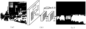
- Figure 7 shows a schematic diagram of an example segmentation.
- Figure 7 (a) is a two-dimensional RGB image
- Figure 7 (b) is a schematic diagram of the Mask R-CNN model
- Figure 7 (c) is an example Segmentation result.
- any obstacle attribute list may include obstacle identification (ID), timestamp, obstacle category (for example, person or car, etc.), obstacle location and obstacle size (length and width), etc.;
- any obstacle list may further include at least one of the following: the outline of the obstacle, the relationship with nearby obstacles, the relative speed, and the pose of the obstacle (for example, the heading of the vehicle).
- the position of the obstacle can be the center point coordinates of the obstacle, which can be expressed in two-dimensional coordinates or three-dimensional coordinates; the relationship with nearby obstacles can be directed from the center point of the obstacle to the center point of the nearby obstacle The vector representation.
- the area within the triangle represents the sensing range of camera 3.
- the sensing range includes two people P1, P2 And a car is car 1 (car1); and the sensing range of lidar b is 360 degrees, and after deducting the self-car part, the obstacles sensed by lidar b are two persons P1 and P2 and two cars, namely car 1 (car1). ), car 2 (car2).
- the respective obstacle attribute lists generated by processing the data collected by the lidar b and the camera a are shown in the list in Fig. 8 respectively. Among them, only a part of the attributes in the obstacle attribute list are examples, which do not represent all of them.
- the relationship with nearby obstacles is represented by the vector that the center of the obstacle points to the center of nearby obstacles.
- the person P1 as an example, draw a circle with its center as a dot and R as a radius.
- the circle contains other obstacles except itself P2 and car1, then P1 and nearby
- the relationship between obstacles can be expressed as a vector pointing to the center of P2 and car1 with the center of P1 as the origin.
- the controller merges the obstacle attribute lists corresponding to all sensors in any sensor group
- the specific method may be: the controller obtains the first obstacle attribute list from the first obstacle attribute list. An unmarked fusion obstacle starts, until all obstacles in the first obstacle attribute list are marked as "fused", and they are matched with obstacles in the second obstacle attribute list; when the second obstacle attribute list When there is a matching obstacle in the obstacle attribute list, merge the attribute data of the obstacle in the first obstacle list and the second obstacle list, and combine the obstacles near the obstacle The attribute data in the first obstacle list and the second obstacle list are merged, and the obstacle and the obstacles near the obstacle are marked as "fused”; when the second obstacle When there is no matching obstacle in the obstacle attribute list, mark the obstacle as "fused”; wherein, the first obstacle attribute list is the obstacle corresponding to the N sensors in any one of the sensing groups A list of obstacle attributes in the attribute list after the fusion of the A obstacle attribute lists, the second obstacle attribute list is the obstacle attribute list after the fusion of the B obstacle attribute lists, N
- the first obstacle attribute list is the obstacle attribute list and camera obtained by lidar point cloud processing. Any one of the obstacle attribute lists obtained from the image, and the second obstacle attribute list is the other one.
- the first obstacle list as the list generated by the camera image as an example: the first unmarked fusion obstacle in the obstacle attribute list generated from the image and the obstacle in the obstacle attribute list generated by the point cloud
- the corresponding obstacle in the list is marked as "fused”, it is considered that the obstacle has no overlapping obstacles; if it is within the preset range, it is further determined whether the types of the two obstacles are the same, if the types are not the same, it is considered that there is no
- the corresponding obstacle in the obstacle attribute list obtained from the point cloud is marked as "fused", and it is considered that the obstacle has no overlapping obstacles; if the type is the same, it is further determined whether the position deviation of the two obstacles is within Within the preset range; if it is not within the preset range, it is considered that there is no
- the respective accessory obstacles can be matched according to the relationship between each and the nearby obstacles.
- the matching process of obstacle a2 near a1 is taken as an example, and the formulas can be used respectively Calculate the error values ⁇ d1 and ⁇ d2 of a2, b2, and b1, and determine the minimum value of the two and it is less than the threshold d, then the two are considered to match.
- Dai is the vector of the relationship between a1 and nearby obstacles
- Dbj is the vector of the relationship between b3 and nearby obstacles.
- x is the value in the x-axis direction of the relation vector
- y is the value in the y-axis direction of the relation vector.
- the attribute data of the two obstacles that are matched are merged separately, that is, the process of merging attribute data is carried out, so that the attribute data of the same obstacle can be merged into the attribute data of one obstacle, so that the merge After that, the same obstacle does not exist, and the purpose of deduplication is achieved.
- the fused obstacle attribute list contains the attribute data of 4 obstacles .
- the obtained attribute list of the fused obstacle can be an attribute list corresponding to a perception group.
- the controller may first predict and compensate the position X of the obstacle with a later time stamp according to its speed V according to the difference ⁇ t of the time stamp.
- N is equal to 2, that is, when there are only two sensors in a sensing group, when N is greater than or equal to 3, that is, when there are 3 or more sensors in a sensing group .
- the obstacle attribute list is merged into one obstacle attribute list.
- the two obstacle attribute lists merged in the last step can be used as the first obstacle attribute list and the second obstacle attribute list, respectively.
- the obstacle attribute lists of the same type of sensors among multiple sensors, and then merge the obtained two obstacle attribute lists.
- various other methods can also be used, as long as the method of fusing all obstacle attribute lists into one obstacle attribute list can be used, which is not limited in this application.
- the fusion method of any two obstacle attribute lists is the same as the fusion method of the two obstacle attribute lists when N is equal to 2, which can be referred to each other, and will not be described in detail here.
- the obstacle attribute lists of the same type of sensors may be first fused, and then the obstacle attribute lists of different types of sensors may be fused.
- an obstacle attribute list corresponding to each perception group can be obtained, that is, the first deduplication result of each perception group is obtained, and the purpose of deduplication within the perception group is achieved.
- the controller performs second deduplication processing on the first deduplication results corresponding to at least two sensing groups in any one of the calculation groups, and the specific method may be: the controller Determine the sensing range corresponding to each sensing group according to the position of the obstacle in the first deduplication result corresponding to each sensing group; the controller determines the sensing range between the at least two sensing groups according to the sensing range corresponding to each sensing group The second deduplication processing is performed on the first deduplication results corresponding to at least two sensing groups with overlapping ranges.
- the controller determines the sensing range corresponding to each sensing group according to the position of the obstacle in the first deduplication result corresponding to each sensing group.
- the specific method may be: the control
- the obstacles corresponding to each perception group are projected into the vehicle's three-dimensional coordinate system, and the obstacle perception range of each perception group is determined according to the center point coordinates of the obstacle.
- the vehicle's three-dimensional coordinate system can be based on the center of the vehicle's rear axle. It is the origin, the z-axis is perpendicular to the horizontal direction, the positive x-axis points to the front of the car, and the y-axis is the horizontal direction.
- the controller may calculate the center point of the obstacle in each perception group according to the following formula Projected into the vehicle's three-dimensional coordinate system
- ⁇ , ⁇ , and ⁇ are the rotation angles of the original obstacle coordinate system to the xyz axis of the vehicle coordinate system
- T xyz is the translation matrix of the xyz axis in the coordinate system change.
- the controller determines the obstacle sensing range of each sensing group according to the coordinates of the center point of the obstacle, and the center point of each obstacle may be the origin, and the circle with the preset radius as the radius
- the overall coverage of the shape area is used as the obstacle perception range of each perception group.
- the overlapping range of the sensing group is judged according to empirical values. For example, the overlap range of two sensing groups with overlap may be as shown in FIG. 10.
- the controller performs second deduplication processing on the first deduplication results corresponding to at least two sensing groups with overlapping ranges.
- the specific method may be as follows: The first unmarked fusion obstacle in the obstacle attribute list starts, until all the obstacles in the third obstacle attribute list are marked as "fused", which respectively match the obstacles in the fourth obstacle attribute list When there is a matching obstacle in the fourth obstacle attribute list, the attribute data of the obstacle in the third obstacle list and the fourth obstacle list are merged, and the The attribute data of the obstacles near the obstacles in the third obstacle list and the fourth obstacle list are merged, and the obstacles and the obstacles near the obstacles are marked as "fused" When there is no matching obstacle in the fourth obstacle attribute list, mark the obstacle as "fused”; wherein, the third obstacle attribute list is M perceptions in any calculation group A list of obstacle attributes after the fusion of the deduplication results corresponding to the C perception groups in the group, the fourth obstacle attribute list is a list of obstacle attributes after the fusion of the deduplication results corresponding to the D perception groups
- the obstacle attribute list corresponding to one perception group is the third obstacle attribute list
- the obstacle attribute list corresponding to the other perception group is the first List of four obstacle attributes.
- M is greater than or equal to 3, that is, when there are 3 or more perception groups in a calculation group
- the two obstacle attribute lists merged in the last step can be used as the third obstacle attribute list and the fourth obstacle attribute list, respectively.
- any two obstacle attribute lists is the same as the fusion principle of the two obstacle attribute lists when N is equal to 2, which can be referred to each other, and will not be described in detail here.
- the specific method for the controller to perform the second deduplication processing on the first deduplication results corresponding to the multiple calculation groups may be: the controller obtains information from the fifth obstacle attribute list Start with the first unmarked fusion obstacle in the fifth obstacle attribute list until all obstacles in the fifth obstacle attribute list are marked as "fused"; respectively match the obstacles in the sixth obstacle attribute list; when the When there is a matching obstacle in the sixth obstacle attribute list, merge the attribute data of the obstacle in the fifth obstacle list and the sixth obstacle list, and combine the obstacles in the vicinity of the obstacle.
- the obstacle attribute list corresponding to one calculation group is the fifth obstacle attribute list
- the obstacle attribute list corresponding to the other calculation group is the sixth obstacle.
- List of attributes For the specific process description of the fusion of the two obstacle attribute lists, please refer to the specific process of the fusion of the two obstacle attribute lists when there are two sensors in the above-mentioned perception group (ie N is equal to 2). The principle is similar and will not be detailed here. description.
- any two obstacle attribute lists is the same as the fusion principle of the two obstacle attribute lists when N is equal to 2, which can be referred to each other, and will not be described in detail here.
- the purpose of calculating the deduplication between groups is achieved, and an obstacle attribute list corresponding to the own vehicle can be obtained, and then the detection result of the target obstacle can be obtained, so that the trajectory of the vehicle can be planned.
- Step 403 The controller performs trajectory planning of the vehicle based on the detection result of the target obstacle.
- the detection result of the target obstacle includes the data of all obstacles around the smart car, and the obstacles are not repeated.
- the controller of the smart car can de-duplicate the obstacle data collected by multiple sensors, so as to obtain effective target obstacle detection results, and then realize the detection based on the target obstacle
- the trajectory planning of the smart car is carried out. It can solve the current problem that obstacles cannot be effectively detected. It can also solve the problem of inaccurate trajectory planning when obstacles collected by multiple sensors in multiple sensor scenes overlap.
- a grouping method can be proposed based on the overlapping relationship between the sensing ranges of the sensors. After the sensing groups divided into the sensors are continued to be grouped, the data in the sensing groups will be de-duplicated at the same time, and then the data between the sensing groups will be de-duplicated.
- the driving of the car is safe; and the relationship with nearby obstacles can be considered in the process of deduplication, which can reduce the process, and because multiple perception groups are divided, the obstacles can be removed through the data deduplication first within the group and then between the groups. High accuracy, and can process data in multiple sensing groups at the same time, which can improve the processing efficiency of deduplication of multiple obstacles.
- the method of the present application considers the obstacle data collected by all sensors in the car, and the comprehensive sensing range can cover the panoramic range of the smart car, thereby providing more comprehensive obstacle data, which is more conducive to the autonomous driving decision-making of the smart car.
- the controller 101 performs the grouping operations in steps 401 and 403, and step 402, and the perceptual computing unit performs the grouping operations on a calculation group. Since the obstacle data collected by the sensor in the middle sensor is subjected to the first deduplication process, since the principle is the same, it will not be described in detail here.
- Step 1101 The controller obtains obstacle data collected by multiple sensors.
- the obstacle data collected by multiple sensors acquired by the controller includes the images collected by the camera 0-camera 5 and the point cloud collected by the lidar a-lidar e.
- Step 1102 According to the sensing ranges of the multiple sensors, the controller divides a camera and a photoradar with overlapping sensing ranges into a sensing group, and finally the following six sensing groups are obtained:
- Perception group (1) camera 0 and lidar a;
- Perception group (2) camera 3 and lidar b;
- Perception group (3) camera 1 and lidar a;
- Perception group (4) camera 4 and lidar d;
- Perception group (6) camera 5 and lidar e.
- Step 1103 The controller divides the six perception groups into three calculation groups according to the perception ranges of the six perception groups, where the perception group (1) and the perception group (2) are divided into one calculation group, and the perception group (3) The perception group (5) is divided into a calculation group, and the perception group (4) and the perception group (6) are divided into a calculation group.
- the controller uses the perception calculation unit A to de-duplicate the data in the calculation group composed of the perception group (1) and the perception group (2), and the perception calculation unit B composes the perception group (3) and the perception group (5)
- the data in the calculation group is de-duplicated
- the data in the calculation group consisting of the perception group (4) and the perception group (6) is de-duplicated by the perception calculation unit C, and the above three processes are carried out simultaneously.
- the calculation process performed by the controller through the perception calculation unit A is taken as an example to continue the description of the above steps: the controller uses the perception calculation unit A to perform the removal of the point cloud of the lidar a in the perception group (1) and the data of the camera 0 Heavy processing, specific implementation:
- Step 1104 The perceptual computing unit A of the controller judges whether the obstacle data is an image, if yes, execute step 1105, otherwise, execute step 1106.
- Step 1105 The controller uses the Mask R-CNN model to perform instance segmentation on the image through the perception calculation unit A, and then executes step 1108.
- Step 1106 The controller projects the point cloud onto the two-dimensional RGB image through the perceptual computing unit A.
- Step 1107 The controller performs instance segmentation on the projected two-dimensional RGB image through the perceptual calculation unit A.
- Step 1108 The controller obtains the obstacle attribute list corresponding to the lidar or the obstacle attribute list corresponding to the camera respectively based on the instance segmentation result through the perception calculation unit A.
- Step 1109 The controller selects the first unmarked fused obstacle in the obstacle attribute list corresponding to the camera through the perception calculation unit A, and matches the obstacle in the obstacle attribute list corresponding to the lidar.
- Step 1110 The controller judges whether the time stamp difference is within a preset range, for example, is less than or equal to 0.4 milliseconds (ms) through the sensing calculation unit A, if yes, execute step 1112, otherwise, execute step 1111.
- a preset range for example, is less than or equal to 0.4 milliseconds (ms) through the sensing calculation unit A, if yes, execute step 1112, otherwise, execute step 1111.
- Step 1111 The controller uses the sensing and computing unit A to mark that the mark is fused, or the mark is not matched to the obstacle, or other mark forms, and then step 1115 is executed.
- Step 1112 The controller judges whether the obstacle types are the same through the perceptual calculation unit A, if yes, execute step 1113; otherwise, execute step 1111.
- Step 1113 The controller judges whether the obstacle position deviation is within a preset range through the perception calculation unit A, if yes, execute step 1114, otherwise execute step 1111.
- Step 1114 The controller calculates whether the area of the obstacle rectangular frame reaches the preset overlap degree based on the size (length and width) of the obstacle through the perception calculation unit A, if yes, execute step 1115, otherwise execute step 1111.
- Step 1115 The controller merges the matched obstacles and the attribute data of nearby obstacles through the perception calculation unit A, and marks them as fused.
- the obstacles a1 and b3 that will be matched in FIG. 9 are merged, and the obstacles a2 and b2 of the attachment are merged.
- Step 1116 The controller judges whether all obstacles in the obstacle attribute list corresponding to the camera are all marked through the perception calculation unit A, if yes, execute step 1117, otherwise execute step 1109.
- Step 1117 The controller adds the attribute data of the unmarked obstacles in the obstacle attribute list corresponding to the lidar to the fused obstacle attribute list through the perception calculation unit A.
- the fused obstacle list is the obstacle attribute list corresponding to the perception group (1).
- the controller uses the perception calculation unit A to de-duplicate the point cloud of the lidar b in the perception group (2) and the data of the camera 3 to obtain the obstacle attribute list corresponding to the perception group (2), You can also refer to the above-mentioned process of step 1104-step 1117, which will not be described in detail here.
- Step 1118 The controller judges through the perception calculation unit A whether the obstacle attribute lists in all perception groups (here, perception group (1) and perception group (2)) have been fused, if yes, go to step 1119, otherwise Go to step 1109.
- Step 1119 The controller projects the obstacles corresponding to each perception group into the vehicle's three-dimensional coordinate system through the perception calculation unit A, and determines the obstacle perception range of each perception group according to the coordinates of the center point of the obstacle.
- Step 1120 The controller determines the overlap range of the two sensing groups through the sensing calculation unit A.
- Step 1121 The controller uses the perception calculation unit A to de-duplicate the obstacle attribute lists corresponding to the two overlapping perception groups.
- the principle of the de-duplication and fusion process of the obstacle attribute lists between the two sensing groups is the same as the above-mentioned fusion process of the obstacle attribute lists corresponding to the two sensors.
- the controller performs deduplication processing on the data in the calculation group consisting of the perception group (3) and the perception group (5) through the perception calculation unit B, and performs the deduplication processing on the perception group (4) and the perception group (4) and the perception group through the perception calculation unit C.
- (6) A method for de-duplicating the data in the formed calculation group, and the controller uses the perception calculation unit A to de-duplicate the point cloud of the lidar a in the perception group (1) and the data of the camera 0
- the methods are the same, you can refer to each other, and will not be described in detail here.
- Step 1122 The controller determines whether the fusion of the obstacle attribute lists between all the sensing groups in all the computing groups is completed, if yes, execute step 1123, otherwise, execute step 1121.
- Step 1123 The controller merges the obstacle attribute list processed by the perception calculation unit A and the obstacle attribute list processed by the perception calculation unit B to obtain a seventh obstacle attribute list.
- Step 1124 The controller merges the seventh obstacle attribute list with the obstacle attribute list processed by the perception computing unit C to obtain the detection result of the target obstacle.
- step 1123 and step 1124 the principle of the fusion process in step 1123 and step 1124 is the same as the process of deduplicating the obstacle attribute lists corresponding to the two sensors.
- step 1109 to step 1117 please refer to the process from step 1109 to step 1117 above, which will not be described in detail here.
- the controller may also first merge the obstacle attribute list processed by the perception computing unit A and the obstacle attribute list processed by the perception computing unit C, and then combine with the obstacle attribute list processed by the perception computing unit C.
- the obstacle attribute list processed by the computing unit B is fused; or the controller may first merge the obstacle attribute list processed by the perception computing unit B and the obstacle attribute list processed by the perception computing unit C. It is then fused with the obstacle attribute list processed by the perception computing unit A, which is not limited in this application.
- Step 1125 The controller performs trajectory planning of the vehicle based on the detection result of the target obstacle.
- the controller of the smart car can de-duplicate the obstacle data collected by multiple sensors, so as to obtain effective target obstacle detection results, and then realize the detection based on the target obstacle
- the trajectory planning of the smart car is carried out. It can solve the current problem that obstacles cannot be effectively detected. It can also solve the problem of inaccurate trajectory planning when obstacles collected by multiple sensors in multiple sensor scenes overlap.
- a grouping method can be proposed based on the overlapping relationship between the sensing ranges of the sensors. After the sensing groups divided into the sensors are continued to be grouped, the data in the sensing groups will be deduplicated at the same time, and then the data between the sensing groups will be deduplicated.
- the method of the present application considers the obstacle data collected by all sensors in the car, and the comprehensive sensing range can cover the panoramic range of the smart car, thereby providing more comprehensive obstacle data, which is more conducive to the autonomous driving decision-making of the smart car.
- trajectory planning method provided by the present application is described in detail above with reference to Figs. 1 to 11, and the trajectory planning device, controller and smart car provided by the present application will be described below with reference to Figs. 12 and 13.
- FIG. 12 is a schematic structural diagram of a device for trajectory planning provided by this application.
- the device 1200 for trajectory planning may include an acquiring unit 1201 and a detecting unit 1202. Specifically:
- the acquiring unit 1201 is configured to acquire obstacle data collected by multiple sensors; the multiple sensors include at least two types of sensors; the detection unit 1202 is configured to acquire obstacle data collected by the multiple sensors Perform de-duplication processing to obtain the detection result of the target obstacle, and perform trajectory planning of the vehicle based on the detection result of the target obstacle.
- the detection unit 1202 performs deduplication processing on the obstacle data collected by the multiple sensors to obtain the detection result of the target obstacle, it is specifically configured to:
- the multiple sensors are divided into multiple sensing groups; any one of the sensing groups includes at least two sensors, the types of the at least two sensors are at least two types, and the sensing ranges of the sensors in any one sensing group overlap;
- the total range of the sensing range of each sensor in all sensing groups covers the panoramic range of the smart car; according to the maximum range composed of the sensing ranges of the multiple sensing groups, the multiple sensing groups are divided into multiple calculation groups; wherein, any A calculation group includes at least two perception groups, and the maximum ranges of the at least two perception groups overlap;
- the obstacle data collected by the sensors in each calculation group is subjected to the first de-duplication processing;
- the first deduplication result corresponding to the calculation group is subjected to the second deduplication process to obtain the second deduplication result.
- the detection unit 1202 when the detection unit 1202 performs the first deduplication processing on the obstacle data collected by the sensors in any calculation group, it is specifically configured to: perform the first deduplication processing on the sensors in each perception group in the any calculation group. Perform the first de-duplication processing on the collected obstacle data; perform the second de-duplication processing on the first de-duplication results corresponding to at least two sensing groups in any one of the calculation groups, to obtain any of the A second deduplication result corresponding to the calculation group, where the second deduplication result includes the detection result of the target obstacle.
- the detection unit 1202 when the detection unit 1202 performs the first de-duplication processing on the obstacle data collected by the sensors in any perception group, it is specifically configured to: based on the obstacles collected by each sensor in the any perception group The data generates an obstacle attribute list corresponding to each sensor, and the obstacle attribute list corresponding to each sensor includes the attribute of at least one obstacle; the obstacle attribute lists corresponding to all sensors in any one of the sensing groups are fused to obtain The obstacle attribute list corresponding to any one of the perception groups.
- the detection unit 1202 when the detection unit 1202 generates the obstacle attribute list corresponding to each sensor based on the obstacle data collected by each sensor, it is specifically used for: when the sensor is a lidar, the data collected by the lidar The obstacle data is point cloud data, and the point cloud data is projected onto a two-dimensional RGB image based on preset virtual camera parameters; the two-dimensional RGB image obtained after projection is segmented to obtain the obstacle corresponding to the lidar Object attribute list; when the sensor is a camera, the obstacle data collected by the camera is a two-dimensional RGB image, and the two-dimensional RGB image is segmented to obtain an obstacle attribute list corresponding to the camera.
- the detection unit 1202 when the detection unit 1202 performs instance segmentation on any two-dimensional RGB image to obtain an obstacle attribute list, it is specifically configured to: input the two-dimensional RGB image into a preset instance segmentation model to obtain an instance segmentation result; An obstacle attribute list is generated based on the instance segmentation result.
- the detection unit 1202 when the detection unit 1202 merges the obstacle attribute lists corresponding to all sensors in any one of the sensing groups, it is specifically configured to: select the first unmarked fused obstacle attribute list from the first obstacle attribute list. Obstacles start until all obstacles in the first obstacle attribute list are marked as "fused", and they are matched with the obstacles in the second obstacle attribute list; when the second obstacle attribute list exists When matching obstacles, merge the attribute data of the obstacles in the first obstacle list and the second obstacle list, and merge the obstacles near the obstacles in the first obstacle The attribute data in the object list and the second obstacle list are merged, and the obstacle and the obstacles near the obstacle are marked as "fused”; when the second obstacle attribute list is not When there is a matching obstacle, mark the obstacle as "fused”; wherein, the first obstacle attribute list is A obstacles in the obstacle attribute list corresponding to the N sensors in any one of the sensing groups The obstacle attribute list after the attribute list fusion, the second obstacle attribute list is the obstacle attribute list after the fusion of B obstacle attribute lists, N is an integer greater
- the detection unit 1202 performs second deduplication processing on the first deduplication results corresponding to at least two sensing groups in any one of the calculation groups, to obtain the second deduplication corresponding to any one of the calculation groups
- it is specifically used to: determine the sensing range corresponding to each sensing group according to the position of the obstacle in the first deduplication result corresponding to each sensing group; to determine the at least two sensing ranges according to the sensing range corresponding to each sensing group The overlap range between the sensing groups; the second deduplication processing is performed on the first deduplication results corresponding to at least two sensing groups with overlapping ranges.
- the detection unit 1202 when it performs second deduplication processing on the first deduplication results corresponding to at least two sensing groups with overlapping ranges, it is specifically configured to: select the first one from the third obstacle attribute list. Obstacles that are not marked for fusion start until all obstacles in the third obstacle attribute list are marked as "fused", which match the obstacles in the fourth obstacle attribute list; when the fourth obstacle When there is a matching obstacle in the attribute list, the attribute data of the obstacle in the third obstacle list and the fourth obstacle list are merged, and the obstacles near the obstacle are located in all the obstacles.
- the detection unit 1202 when the detection unit 1202 performs the second deduplication processing on the first deduplication results corresponding to the multiple calculation groups, it is specifically configured to: merge the first unmarked result from the fifth obstacle attribute list Until all obstacles in the fifth obstacle attribute list are marked as "fused", which match the obstacles in the sixth obstacle attribute list; when the sixth obstacle attribute list is When there is a matching obstacle, merge the attribute data of the obstacle in the fifth obstacle list and the sixth obstacle list, and combine the obstacles near the obstacle in the fifth obstacle list.
- the obstacle list and the attribute data in the sixth obstacle list are merged, and the obstacles and the obstacles near the obstacles are marked as "fused"; when the sixth obstacle attribute list is When there is no matching obstacle, the obstacle is marked as "fused”; wherein, the fifth obstacle attribute list is after the fusion of E obstacle attribute lists in the obstacle attribute lists corresponding to the L calculation groups
- the difference between the timestamps of the two obstacles is less than the preset range, the two obstacles belong to the same obstacle type, and the position deviation of the two obstacles is within the preset range
- the border area of the two obstacles overlaps.
- trajectory planning device 1200 of the embodiment of the present application can be implemented by an application-specific integrated circuit (ASIC) or a programmable logic device (PLD).
- ASIC application-specific integrated circuit
- PLD programmable logic device
- the above-mentioned PLD can be complicated.
- Programmable logic device complex programmable logical device, CPLD
- field-programmable gate array field-programmable gate array
- FPGA field-programmable gate array
- GAL general array logic
- the trajectory planning device 1200 and its various modules may also be software modules.
- the device 1200 for trajectory planning may correspond to the method described in the embodiment of the present application, and the above-mentioned and other operations and/or functions of each unit in the device 1200 for trajectory planning are used to implement FIG. 4 or FIG. 4, respectively.
- the corresponding process of each method in 11 will not be repeated here.
- the obstacle data collected by multiple sensors can be deduplicated during the driving process of the smart car, so as to obtain effective target obstacle detection results, and then realize the detection result based on the target obstacle Carry out the trajectory planning of smart cars. It can solve the current problem that obstacles cannot be effectively detected. It can also solve the problem of inaccurate trajectory planning when obstacles collected by multiple sensors in multiple sensor scenes overlap.
- a grouping method can be proposed based on the overlapping relationship between the sensing ranges of the sensors. After the sensing groups divided into the sensors are continued to be grouped, the data in the sensing groups will be de-duplicated at the same time, and then the data between the sensing groups will be de-duplicated.
- the driving of the car is safe; and the relationship with nearby obstacles can be considered in the process of deduplication, which can reduce the process, and because multiple perception groups are divided, the obstacles can be removed through the data deduplication first within the group and then between the groups. High accuracy, and can process data in multiple sensing groups at the same time, which can improve the processing efficiency of deduplication of multiple obstacles.
- the method of the present application considers the obstacle data collected by all sensors in the car, and the comprehensive sensing range can cover the panoramic range of the smart car, thereby providing more comprehensive obstacle data, which is more conducive to the autonomous driving decision-making of the smart car.
- FIG. 13 is a schematic structural diagram of a controller provided by an embodiment of the application, and the controller is applied to the system shown in FIG. 2 or FIG. 3 for implementing the trajectory planning method shown in FIG. 4 or FIG. 11 .
- the controller 1300 may include: a processor 1301, a memory 1302, and a bus 1303. Among them, the processor 1301 and the memory 1302 communicate through the bus 1303, and may also communicate through other means such as wireless transmission.
- the memory 1302 is used to store instructions, and the processor 1301 is used to execute the instructions stored in the memory 1302.
- the memory 1302 stores program codes, and the processor 1301 can call the program codes stored in the memory 1302 to perform the following operations:
- the multiple sensors include at least two types of sensors; perform deduplication processing on the obstacle data collected by the multiple sensors to obtain the detection result of the target obstacle; based on the The detection result of the target obstacle is used to plan the vehicle trajectory.
- the controller 1300 shown in FIG. 13 further includes a memory 1304 and a communication interface 1305, where the memory 1304 may be physically integrated with the processor 1301, or exist in the processor 1301 or in the form of an independent unit.
- the computer program 13042 may be stored in the memory 1304 or the memory 1302.
- the computer program code 13042 (for example, a program to be debugged, etc.) stored in the memory 1302 is copied to the memory 1304, and then executed by the processor 1301.
- the kernel 13041 can also be run in the memory 1304.
- the processor 1301 may be a central processing unit (CPU), and the processor 1301 may also be other general-purpose processors or digital signal processing (DSPDSP). , Application-specific integrated circuit (ASIC), programmable logic device (programmable logic device, PLD); the above-mentioned PLD can be a complex programmable logic device (complex programmable logic device, CPLD), field programmable gate array ( Field-programmable gate array (FPGA), generic array logic (GAL), or any combination thereof; or the processor 1301 may be other programmable logic devices, discrete gates or transistor logic devices, discrete hardware components, etc.
- the general-purpose processor may be a microprocessor or any conventional processor.
- the controller shown in FIG. 13 may also include a processor 1306.
- the processor 1301 and the processor 1306 may be the same type or different types of processors, and the number of processor cores in each type of processor is different. It constitutes a limitation on this application.
- the memory 1302 may include a read-only memory and a random access memory, and provides instructions, programs, data, and the like to the processor 1301.
- the program may include program code, and the program code includes computer operation instructions.
- the memory 1302 may also include a non-volatile random access memory.
- the memory 1302 may also store device type information.
- the memory 1302 may be a volatile memory or a non-volatile memory, or may include both volatile and non-volatile memory.
- the non-volatile memory can be read-only memory (ROM), programmable read-only memory (programmable ROM, PROM), erasable programmable read-only memory (erasable PROM, EPROM), and electrically available Erase programmable read-only memory (electrically EPROM, EEPROM) or flash memory.
- the volatile memory may be random access memory (RAM), which is used as an external cache.
- RAM random access memory
- SRAM static random access memory
- DRAM dynamic random access memory
- SDRAM synchronous dynamic random access memory
- Double data rate synchronous dynamic random access memory double data date SDRAM, DDR SDRAM
- enhanced SDRAM enhanced synchronous dynamic random access memory
- SLDRAM synchronous connection dynamic random access memory
- direct rambus RAM direct rambus RAM
- the bus 1303 may also include an address bus, a power bus, a control bus, and a status signal bus.
- the bus 1303 may be a peripheral component interconnect (PCI) bus or an extended industry standard architecture (EISA) bus, etc., or it may be a controller area network (CAN), and It may be a vehicle-mounted Ethernet (Ethernet) or other internal buses to realize the connection of the various devices/devices shown in FIG. 13.
- PCI peripheral component interconnect
- EISA extended industry standard architecture
- CAN controller area network
- Ethernet vehicle-mounted Ethernet
- controller 1300 may correspond to the device 1200 for trajectory planning in the embodiment of the present application, and may correspond to the operation steps in which the controller in the method shown in FIG. 4 or FIG. 11 is the main body.
- the above-mentioned and other operations and/or functions of each module in the controller 1300 are used to implement the corresponding process of each method in FIG. 4 or FIG. 11, and are not repeated here for brevity.
- the obstacle data collected by multiple sensors can be deduplicated during the driving process of the smart car, so as to obtain effective target obstacle detection results, and then realize intelligence based on the target obstacle detection results Trajectory planning of the car. It can solve the current problem that obstacles cannot be effectively detected. It can also solve the problem of inaccurate trajectory planning when obstacles collected by multiple sensors in multiple sensor scenes overlap.
- a grouping method can be proposed based on the overlapping relationship between the sensing ranges of the sensors. After the sensing groups divided into the sensors are continued to be grouped, the data in the sensing groups will be de-duplicated at the same time, and then the data between the sensing groups will be de-duplicated.
- the driving of the car is safe; and the relationship with nearby obstacles can be considered in the process of deduplication, which can reduce the process, and because multiple perception groups are divided, the obstacles can be removed through the data deduplication first within the group and then between the groups. High accuracy, and can process data in multiple sensing groups at the same time, which can improve the processing efficiency of deduplication of multiple obstacles.
- the method of the present application considers the obstacle data collected by all sensors in the car, and the comprehensive sensing range can cover the panoramic range of the smart car, thereby providing more comprehensive obstacle data, which is more conducive to the autonomous driving decision-making of the smart car.
- the present application also provides a smart car, which may include the aforementioned controller or trajectory planning device.
- the present application also provides an in-vehicle system.
- the in-vehicle system includes a plurality of sensors and a controller, or includes a plurality of sensors, a controller, and a plurality of perception calculation units.
- the application also provides a trajectory planning system, which includes at least one smart car.
- a trajectory planning system which includes at least one smart car.
- the above-mentioned components or devices are respectively used to execute the operation steps of the corresponding execution main body in the method shown in FIG. 4 or FIG. 11. For the sake of brevity, details are not described herein again.
- the above-mentioned embodiments may be implemented in whole or in part by software, hardware, firmware or any other combination.
- the above-mentioned embodiments may be implemented in the form of a computer program product in whole or in part.
- the computer program product includes one or more computer instructions.
- the computer may be a general-purpose computer, a special-purpose computer, a computer network, or other programmable devices.
- the computer instructions may be stored in a computer-readable storage medium, or transmitted from one computer-readable storage medium to another computer-readable storage medium.
- the computer instructions may be transmitted from a website, computer, server, or data center.
- the computer-readable storage medium may be any available medium that can be accessed by a computer or a data storage device such as a server or a data center that includes one or more sets of available media.
- the usable medium may be a magnetic medium (for example, a floppy disk, a hard disk, and a magnetic tape), an optical medium (for example, a DVD), or a semiconductor medium.
- the semiconductor medium may be a solid state drive (SSD).
- the disclosed system, device, and method can be implemented in other ways.
- the device embodiments described above are merely illustrative.
- the division of the units is only a logical function division, and there may be other divisions in actual implementation, for example, multiple units or components may be combined It can be integrated into another system, or some features can be ignored or not implemented.
- the displayed or discussed mutual coupling or direct coupling or communication connection may be indirect coupling or communication connection through some interfaces, devices or units, and may be in electrical, mechanical or other forms.
- the units described as separate components may or may not be physically separated, and the components displayed as units may or may not be physical units, that is, they may be located in one place, or they may be distributed on multiple network units. Some or all of the units can be selected according to actual needs to achieve the purpose of the technical solution of the present application.
Landscapes
- Engineering & Computer Science (AREA)
- Physics & Mathematics (AREA)
- Radar, Positioning & Navigation (AREA)
- Remote Sensing (AREA)
- General Physics & Mathematics (AREA)
- Automation & Control Theory (AREA)
- Electromagnetism (AREA)
- Computer Networks & Wireless Communication (AREA)
- Aviation & Aerospace Engineering (AREA)
- Mechanical Engineering (AREA)
- Transportation (AREA)
- Multimedia (AREA)
- Theoretical Computer Science (AREA)
- Human Computer Interaction (AREA)
- Optics & Photonics (AREA)
- Traffic Control Systems (AREA)
Abstract
一种轨迹规划的方法、装置、控制器(101)和智能车,用以实现有效检测障碍物进而规划智能车的行驶轨迹;轨迹规划的方法包括:智能车的控制器(101)获取多个传感器采集的障碍物数据后,对多个传感器采集的障碍物数据进行去重处理得到目标障碍物的检测结果,最后基于目标障碍物的检测结果进行车辆的轨迹规划;结合多个传感器的障碍物数据,全面检测智能车周围的障碍物,并且有效去除重复的障碍物,用于合理规划智能车的行驶轨迹,提高自动驾驶的安全性。
Description
相关申请的交叉引用
本申请要求在2019年12月31日提交中国专利局、申请号为201911417562.5、申请名称为“轨迹规划的方法、装置、控制器和智能车”的中国专利申请的优先权,其全部内容通过引用结合在本申请中。
本申请涉及智能车(smart/inteligent car)领域,尤其涉及一种自动驾驶(automatic driving,ADS)过程中的轨迹规划的方法、装置、控制器和智能车。
自动驾驶中障碍物感知是指自动驾驶过程中传感器检测自车周围的障碍物信息,是车辆实现自动驾驶的基础。当前检测障碍物的方法主要依赖于车载传感器。通常每辆智能车会利用激光雷达和高精地图相配合的方式确认智能车的障碍物信息,进而规划智能车的行驶轨迹,但是,激光雷达受天气影响比较大,使用场景和精度均存在局限性。另一种方式则是利用摄像头作为检测设备,由于摄像头只能采集二维图像,需要通过复杂的处理过程才能识别图像中物体的类别,但是,又无法识别同一类物体中不同个体,导致摄像头也无法满足智能车在自动驾驶过程对各种复杂场景中障碍物检测的需求,无法合理规划智能车的行驶轨迹,影响自动驾驶的安全性。因此,如何有效检测障碍物进而规划智能车的行驶轨迹成为亟待解决的技术问题。
发明内容
本申请提供一种轨迹规划的方法、装置、控制器和智能车,用以实现有效检测障碍物进而规划智能车的行驶轨迹。
第一方面,本申请提供了一种轨迹规划的方法,方法可以由智能车中的控制器实现。控制器获取多个传感器采集的障碍物数据后,对多个传感器采集的障碍物数据进行去重处理得到目标障碍物的检测结果,最后基于目标障碍物的检测结果进行车辆的轨迹规划,其中,多个传感器包含至少两种类型的传感器。
通过上述方法,可以解决目前无法满足智能车的障碍物检测的需求导致无法合理规划智能车的行驶轨迹的问题。本方法可以结合多个传感器的障碍物数据,全面检测智能车周围的障碍物,并且可以有效去除重复的障碍物,可以用于合理规划智能车的行驶轨迹,提高自动驾驶的安全性。
在一个可能的设计中,控制器对多个传感器采集的障碍物数据进行去重处理得到目标障碍物的检测结果时,具体方法可以为:控制器根据多个传感器的感知范围将多个传感器划分为多个感知组,并根据多个感知组的感知范围组成的最大范围将多个感知组分成多个计算组;然后分别对每个计算组中的传感器采集的障碍物数据进行第一去重处理后,对多个计算组对应的第一去重结果进行第二去重处理,得到第二去重结果;其中,任一个计算 组包含至少两个感知组,至少两个感知组的最大范围之间有重叠;任一个感知组包含至少两个传感器,至少两个传感器的类型为至少两种类型,任一个感知组中的传感器的感知范围有重叠;所有感知组中各个传感器的感知范围的总范围覆盖智能车的全景范围。
通过上述方法,控制器可以将多个传感器先划分为感知组,再将感知组划分为计算组,然后同时对几个计算组中的数据做去重处理,最后再对计算组间的数据去重,这样可以同时执行多个去重过程,进而提高障碍物去重精度和效率。
在另一个可能的设计中,控制器对任一个计算组中的传感器采集的障碍物数据进行第一去重处理时,具体方法可以为:控制器对任一个计算组中每个感知组中的传感器采集的障碍物数据进行第一去重处理,然后对任一个计算组中至少两个感知组对应的第一去重结果进行第二去重处理,得到任一个计算组对应的第二去重结果,第二去重结果包括目标障碍物的检测结果。通过上述方法,可以同时对几个感知组中的障碍物数据去重后,再对感知组间的数据去重,可以同时执行过个去重过程,提高去重效率,并且组内去重后再组间去重可以提高去重精度。
在另一个可能的设计中,控制器对任一个感知组中的传感器采集的障碍物数据进行第一去重处理时,具体方法可以为:控制器基于任一个感知组中每个传感器采集的障碍物数据生成每个传感器对应的障碍物属性列表,然后对该感知组中所有传感器分别对应的障碍物属性列表进行融合,得到任一个感知组对应的障碍物属性列表,其中每个传感器对应的障碍物属性列表包含至少一个障碍物的属性。通过上述方法可以把一个感知组中所有传感器识别到的相同障碍物的属性数据合并在一起,使得感知组对应的障碍物属性列表中没有重复的障碍物,进而提高障碍物检测的准确性。
在另一个可能的设计中,控制器基于每个传感器采集的障碍物数据生成每个传感器对应的障碍物属性列表时,具体方法可以为:当传感器为激光雷达时,激光雷达采集的障碍物数据为点云数据,控制器可以先基于预设的虚拟相机参数将点云数据投影到二维RGB图像上,再对投影后得到的二维RGB图像进行实例分割,得到激光雷达对应的障碍物属性列表;当传感器是摄像头时,摄像头采集的障碍物数据为二维RGB图像,控制器可以直接对二维RGB图像进行实例分割,得到摄像头对应的障碍物属性列表。通过上述方法可以分别针对不同类型的传感器得到相应的障碍物属性列表,以便于后续进行障碍物属性数据的融合。
在另一个可能的设计中,控制器对任一个二维RGB图像进行实例分割,得到障碍物属性列表时,具体方法可以为:控制器将二维RGB图像输入预设的实例分割模型,得到实例分割结果后,基于实例分割结果生成障碍物属性列表。通过上述方法,可以通过实例分割模型对传感器对应的二维RGB图像进行分析,确定障碍物的属性,进而得到传感器对应的障碍物属性列表。
在另一个可能的设计中,控制器对任一个感知组中所有传感器分别对应的障碍物属性列表进行融合时,具体方法可以为:从第一障碍物属性列表中第一个未标记融合的障碍物开始,直至第一障碍物属性列表中所有障碍物均标记为“已融合”,分别与第二障碍物属性列表中的障碍物匹配;当第二障碍物属性列表中存在匹配的障碍物时,将障碍物在第一障碍物列表和第二障碍物列表中的属性数据进行合并,以及将障碍物附近的障碍物在第一障碍物列表和第二障碍物列表中的属性数据进行合并,并将障碍物以及障碍物附近的障碍物标记为“已融合”;当第二障碍物属性列表中不存在匹配的障碍物时,将障碍物标记“已 融合”;其中,第一障碍物属性列表为任一个感知组中N个传感器对应的障碍物属性列表中A个障碍物属性列表融合后的障碍物属性列表,第二障碍物属性列表为B个障碍物属性列表融合后的障碍物属性列表,N为大于或等于2的整数,A为大于或者等于1的整数,B为大于或者等于1的整数,且A+B=N。通过上述方法,可以将一个感知组中所有传感器识别到的相同障碍物的属性数据合并在一起,使得感知组对应的障碍物属性列表中没有重复的障碍物,进而提高障碍物检测的准确性;并且在融合过程中结合障碍物与附近障碍物之间的关系确定重复的障碍物可以提高去重效率。
在另一个可能的设计中,A个传感器可以相同或者不同类型的传感器;B个传感器可以是相同或者不同类型的传感器。
在另一个可能的设计中,控制器对任一个计算组中至少两个感知组对应的第一去重结果进行第二去重处理,得到任一个计算组对应的第二去重结果时,具体方法可以为:控制器根据每个感知组对应的第一去重结果中障碍物的位置,确定每个感知组对应的感知范围,并根据每个感知组对应的感知范围确定至少两个感知组间的重叠范围;最后对有重叠范围的至少两个感知组对应的第一去重结果进行第二去重处理。通过上述方法,可以将不同感知组间有重复的障碍物去除,以保证一个计算组对应的障碍物没有重复的障碍物,进而提高障碍物检测的准确性。
在另一个可能的设计中,控制器对有重叠范围的至少两个感知组对应的第一去重结果进行第二去重处理时,具体方法可以为:控制器从第三障碍物属性列表中第一个未标记融合的障碍物开始,直至第三障碍物属性列表中所有障碍物均标记为“已融合”,分别与第四障碍物属性列表中的障碍物匹配;当第四障碍物属性列表中存在匹配的障碍物时,将障碍物在第三障碍物列表和第四障碍物列表中的属性数据进行合并,以及将障碍物附近的障碍物在第三障碍物列表和第四障碍物列表中的属性数据进行合并,并将障碍物以及障碍物附近的障碍物标记为“已融合”;当第四障碍物属性列表中不存在匹配的障碍物时,将障碍物标记为“已融合”;其中,第三障碍物属性列表为任一个计算组中M个感知组中C个感知组对应的去重结果融合后的障碍物属性列表,第四障碍物属性列表为D个感知组对应的去重结果融合后的障碍物属性列表,M为大于或者等于2的整数,C为大于或者等于1的整数,D为大于或者等于1的整数,且C+D=M。
通过上述方法,可以将一个计算组中所有感知组对应的相同障碍物的属性数据合并在一起,使得一个计算组对应的障碍物属性列表中没有重复的障碍物,进而提高障碍物检测的准确性;并且在融合过程中结合障碍物与附近障碍物之间的关系确定重复的障碍物可以提高去重效率。
在另一个可能的设计中,控制器对多个计算组对应的第一去重结果进行第二去重处理时,具体方法可以为:控制器从第五障碍物属性列表中第一个未标记融合的障碍物开始,直至第五障碍物属性列表中所有障碍物均标记为“已融合”,分别与第六障碍物属性列表中的障碍物匹配;当第六障碍物属性列表中存在匹配的障碍物时,将障碍物在第五障碍物列表和第六障碍物列表中的属性数据进行合并,以及将障碍物附近的障碍物在第五障碍物列表和第六障碍物列表中的属性数据进行合并,并将障碍物以及障碍物附近的障碍物标记为“已融合”;当第六障碍物属性列表中不存在匹配的障碍物时,将障碍物标记为“已融合”;其中,第五障碍物属性列表为L个计算组对应的障碍物属性列表中E个障碍物属性列表融合后的障碍物属性列表,第六障碍物属性列表为F个障碍物属性列表融合后的障碍 物属性列表,L为计算组的总个数,L为大于或等于2的整数,E为大于或者等于1的整数,F为大于或者等于1的整数,且E+F=L。通过上述方法,可以将所有计算组对应的相同障碍物的属性数据合并在一起,使得最终障碍物检测结果对应的障碍物属性列表中没有重复的障碍物,进而提高障碍物检测的准确性;并且在融合过程中结合障碍物与附近障碍物之间的关系确定重复的障碍物可以提高去重效率。
在另一个可能的设计中,当同时满足以下条件时说明存在匹配的障碍物:两个障碍物的时间戳的差小于预设范围、两个障碍物属于同一障碍物类型、两个障碍物的位置偏差在预设范围内且两个障碍物的边框面积有重叠。通过上述方法,可以准确地确定两个障碍物是相同的障碍物,进而对相同的障碍物的属性数据进行合并,以达到障碍物去重的目的。
第二方面,本申请提供了一种轨迹规划的装置,轨迹规划的装置包括用于执行第一方面或第一方面任一种可能设计中的轨迹规划方法的各个模块或单元,例如处理单元和获取单元。
第三方面,本申请提供了一种控制器,控制器包括处理器和存储器,控制器运行时,所述处理器执行所述存储器中所存储的计算机执行计算机程序或指令,以使所述控制器执行如上述第一方面或第一方面任一种可能设计中所示的相应的方法。
第四方面,本申请提供了一种智能车,所述智能车可以包括上述第二方面任一所述的轨迹规划的装置或第三方面中任一所述的智能驾驶域控制器。
第五方面,本申请提供了一种车载系统,所述车载系统可以包括上述涉及的控制器和多个传感器。
第六方面,本申请提供一种计算机可读存储介质,所述计算机可读存储介质中存储有程序或指令,当其在计算机上运行时,使得计算机执行第一方面或第一方面任一种可能的设计中所述的方法。
第七方面,本申请提供了一种包含指令的计算机程序产品,当其在计算机上运行时,使得计算机执行第一方面或第一方面任一种可的设计中所述的方法。
本申请在上述各方面提供的实现方式的基础上,还可以进行进一步组合以提供更多实现方式。
图1为本申请提供的一种轨迹规划的方法适用的车载系统的架构示意图;
图2为本申请提供的另一种轨迹规划的方法适用的车载系统的架构示意图;
图3为本申请提供的另一种轨迹规划的方法适用的车载系统的架构示意图;
图4为本申请提供的一种轨迹规划的方法的流程图;
图5为本申请提供的一种点云的示意图;
图6为本申请提供的一种Mask R-CNN模型的结构示意图;
图7为本申请提供的一种实例分割的示意图;
图8为本申请提供的一种障碍物属性列表的示意图;
图9为本申请提供的一种障碍物属性列表的融合示意图;
图10为本申请提供的一种两个感知组的重叠范围的示意图;
图11为本申请提供的一种轨迹规划的方法的示例的流程图;
图12为本申请提供的一种轨迹规划的装置的结构示意图;
图13为本申请提供的一种控制器的结构图。
下面将结合附图对本申请作进一步地详细描述。
本申请实施例提供的轨迹规划的方法适用于车载系统,所述车载系统可以部署于智能车中。所述车载系统的架构中至少包括多个传感器和控制器,其中,多个传感器可以包含激光雷达、摄像头和毫米波雷达等中一种或多种。示例性的,图1示出了多个传感器在一辆智能车中的布局示意图。例如,在图1中,所述多个传感器包括激光雷达a、激光雷达b……激光雷达e共5个激光雷达,以及摄像头0-5共6个摄像头。
应理解,图1仅作为一种示例,还可以包括更多或者更少的传感器,也可以包含其他类型的传感器,本申请对此不作限定。
所述多个传感器分别采集环境数据输入到所述控制器中,其中激光雷达采集的数据为点云,摄像头采集的数据为图像。其中,所述多个传感器分别有对应的感知范围,每个传感器的感知范围即为每个传感器对障碍物的探测范围。所述控制器可以基于预设原则将所述多个传感器划分成多个感知组。例如,所述控制器可以根据所述多个传感器的感知范围,将感知范围有重叠的至少两个传感器划分为一个感知组。例如,以图1为例,所述控制器可以将感知范围重叠的一个摄像头和一个激光雷达划分为一个感知组,可以分为以下6组:
感知组(1):摄像头0和激光雷达a;
感知组(2):摄像头3和激光雷达b;
感知组(3):摄像头1和激光雷达a;
感知组(4):摄像头4和激光雷达d;
感知组(5):摄像头2和激光雷达c;
感知组(6):摄像头5和激光雷达e。
所述控制器可以根据感知组内传感器的安装位置判断感知组间总感知范围存在重叠的可能性,然后,将有重叠的两个或者多个感知组的传感器采集的数据分配给一个感知计算单元进行去重处理。例如,将感知组(1)和感知组(2)的数据分配给感知计算单元A,将感知组(3)和感知组(5)的数据分配给感知计算单元B,将感知组(4)和感知组(6)的数据分配给感知计算单元C。
可选地,同一个传感器可以归属于一个感知组,同一个传感器也可以归属于多个感知组。
可选地,所述车载系统的架构中可以包含多个感知计算单元,感知计算单元用于对划分的感知组中的几个感知组中的数据进行去重处理,例如,图1所示的感知计算单元A、B、C。其中,感知计算单元可以是独立于所述控制器以板卡等形式存在,例如,图2所示的车载系统架构示意图中,控制器101与感知计算单元A、B、C的部署关系;感知计算单元也可以部署于所述控制器中,例如,图3所示的车载系统架构示意图中控制器101与感知计算单元A、B、C的部署关系。
其中图2或图3中的控制器101可以分别将感知单元A、B、C处理得到的结果进一步进行去重得到最终的障碍物检测结果,以使后续基于最终的障碍物检测结果进行智能车的轨迹规划。
可选地,控制器101具体由处理器实现,处理器包括中央处理器(central processing unit, CPU)或者具备处理功能的设备或模块。例如,控制器101可以是车载移动数据中心(mobile data center,MDC)。
需要说明的是,图1、图2、图3中控制器、传感器或感知计算单元的数量和布局仅仅为示例,在实际中可以有多种实现方式,本申请此处不作具体限定。其中,图1仅示出了智能车中多个传感器的布局情况,图2和图3分别是在图1的基础上布局了控制器和感知计算单元的情况示意。其中图2中感知计算单元是独立于控制器存在的,也即感知计算单元和控制器独立部署;而图3是感知计算单元作为控制器的一部分,也即将感知计算单元部署在控制器中。在以下的轨迹规划的方案介绍中,以感知计算单元部署于控制器内为例,以控制器为执行主体为例说明。
基于上述描述,本申请实施例提供了一种轨迹规划的方法,适用于图1或3所示的系统。所述方法可以由智能车中的控制器实现。参阅图4所示,所述方法的具体流程可以包括:
步骤401:控制器获取多个传感器采集的障碍物数据;所述多个传感器包含至少两种类型的传感器。
其中,障碍物是能够阻碍或迟滞车辆运动的地形、地物和工程设施等的统称。在本申请中,障碍物可以为人、车、路面基础设施和道路标识等等。
所述多个传感器可以包含激光雷达、摄像头、毫米波雷达等多种类型的传感器。其中,激光雷达采集的障碍物数据是点云,也可以称为点云图像,点云图像可以是三维图像,例如图5所示的点云图像所示。摄像头采集的障碍物数据是图像,具体为二维红R(red)绿G(green)蓝B(blue)图像。毫米波雷达采集的障碍物数据也为点云。
步骤402:所述控制器对所述多个传感器采集的障碍物数据进行去重处理,得到目标障碍物的检测结果。
在一种具体的实施方式中,所述控制器在对所述多个传感器采集的障碍物数据进行去重处理,得到目标障碍物的检测结果时,具体方法可以为:
所述控制器根据所述多个传感器的感知范围,将所述多个传感器划分为多个感知组;其中任一个感知组包含至少两个传感器,所述至少两个传感器的类型为至少两种类型,任一个感知组中的传感器的感知范围有重叠;所有感知组中各个传感器的感知范围的总范围覆盖智能车的全景范围;
所述控制器根据所述多个感知组的感知范围组成的最大范围,将所述多个感知组分成多个计算组;其中,任一个计算组包含至少两个感知组,所述至少两个感知组的最大范围之间有重叠;
所述控制器分别对每个计算组中的传感器采集的障碍物数据进行第一去重处理;
所述控制器对所述多个计算组对应的第一去重结果进行第二去重处理,得到第二去重结果,即得到所述目标障碍物的检测结果。
具体的,根据每种传感器参数,确定该传感器的感知范围,也即对周围环境中障碍物的探测范围。所述控制器根据所述多个传感器的感知范围将所述多个传感器划分为多个感知组时,可以将感知范围存在重叠的传感器划分为一个感知组,其中,感知范围存在重叠的传感器是指两个具有部分重叠的传感器划分至一个传感器组中,部分重叠的范围可以根据具体实施中要求设置不同阈值,控制重叠区域的大小,并基于此进一步划分传感器组。可选的,可以将重叠范围大于预设重叠率的多个传感器划分为一个感知组,其中,预设重 叠率是指传感器之间的重叠范围占有重叠的几个传感器的总感知范围的百分比。当然,在实际可以尽可能将重叠率最大的重叠范围的传感器划分为一个感知组。所述控制器具体划分的时候依赖于传感器的在智能车中的安装位置,一般安装位置临近的传感器才会有重叠范围的可能性,例如,图1中的传感器的感知组划分的示例,在每个感知组中均包含一个摄像头和一个激光雷达两种类型的传感器,每个感知组中的传感器的安装位置都很临近,且考虑了尽可能重叠范围最大,且保证所有感知组的总的感知范围覆盖智能车的全景范围,即智能车360度各个角度都覆盖。
在一种示例性的实施方式中,基于组成不同感知组的传感器的安装位置,可以确定各个感知组的传感器的感知范围组成的最大范围,并将感知组间有重叠的至少两个感知组划分为一个计算组,当然感知组间的重叠范围同样可以以预设重叠率作为依据。例如,仍以图1为例,将划分好的感知组(1)和感知组(2)分成一个计算组,将感知组(3)和感知组(5)分成一个计算组,将感知组(4)和感知组(6)分成一个计算组。
进一步地,分成多个计算组之后,所述控制器可以同时分别对所有计算组中的障碍物数据进行去重处理。在一种可选的实施方式中,所述控制器对任一个计算组中的传感器采集的障碍物数据进行去重处理,具体方法可以为:所述控制器对所述任一个计算组中每个感知组中的传感器采集的障碍物数据进行第一去重处理后,对所述任一个计算组中至少两个感知组对应的第一去重结果进行第二去重处理,得到所述任一个计算组对应的第二去重结果。
需要说明的是,第一去重处理是指的感知组内传感器的障碍物的数据进行去重,第二去重处理指的是感知组间数据的去重。在下面的计算组间的数据去重也称为第二去重处理。
需要说明的是,所述控制器中可以包含多个单元或模块,例如,感知计算单元,每一个单元或模块对其中一个计算组进行上述去重处理。
在一种可选的实施方式中,所述控制器对任一个感知组中的传感器采集的障碍物数据进行第一去重处理,具体方法可以为:所述控制器基于所述任一个感知组中每个传感器采集的障碍物数据生成每个传感器对应的障碍物属性列表,每个传感器对应的障碍物属性列表包含至少一个障碍物的属性;并对所述任一个感知组中所有传感器分别对应的障碍物属性列表进行融合,得到所述任一个感知组对应的障碍物属性列表,即得到任一个感知组对应的第一去重结果。
在一种可选的实施方式中,所述控制器在对一个感知组中的每个传感器采集的障碍物数据处理时,基于每个传感器采集的障碍物数据生成所述每个传感器对应的障碍物属性列表具体方法可以为:当传感器为激光雷达时,所述激光雷达采集的障碍物数据为点云数据,基于预设的虚拟相机参数将所述点云数据投影到二维RGB图像上;对投影后得到的二维RGB图像进行实例分割,得到所述激光雷达对应的障碍物属性列表;当传感器是摄像头时,所述摄像头采集的障碍物数据为二维RGB图像,对所述二维RGB图像进行实例分割,得到所述摄像头对应的障碍物属性列表。
在一种示例中,当传感器是激光雷达时,所述控制器基于预设的虚拟相机参数将所述点云数据投影到二维RGB图像上的过程可以为:
(1)预设虚拟相机参数。
相机的定义如C=K[R T],其中R是表示相机的外参旋转的部分,是一个3X3的矩阵,例如R如下矩阵表示:

其中α,β,γ表示相机分别为绕x,y,z轴旋转角度;
T是一个3X1的矩阵,表示相机的平移参数;
K是相机的内参,对相机内参进行标定校准,包括焦距和畸变等参数,例如K如下矩阵所示:

其中,α
x,α
y为相机的焦距,一般情况下二者相等;γ为坐标轴倾斜参数,理想情况下为0;u
0,v
0为主点坐标(相对于成像平面)。
(2)基于预设的虚拟相机参数将所述点云数据投影到二维RGB图像上,这里可以采用卡茨(Katz)投影方法,当然还可以是其他方法,本申请不作具体限定。
在投影过程中,所述控制器确定点云中的哪些点从相机可见是非常重要的。以Katz投影的算法为例。该算法不仅能够删除掉点云中的相机不可见的所有点,还能够消除点云中的相互靠近的点以加速算法。其中,相互靠近的点可以为距离小于预设阈值的点。首先通过在点云中的所有点周围定义一个半径为R的球体并将相机C放置在原点中来执行。点云中的点的球形翻转使用以下公式计算:

其中,
 为翻转之后点的坐标,p
i为翻转前的点的坐标。
为翻转之后点的坐标,p
i为翻转前的点的坐标。
所述控制器当确定哪些点可见时,将3D点基于以下公式投影到像素中:
 其中,
其中,
 为投影到图像上点的坐标,C为定义的相机参数。
因为存在多个点投影到同一个像素中,所述控制器通过下面的高斯函数来计算不同点云投影到相应图像像素中的权重大小:

其中dist表示像素和点位置之间的距离。
在一种可选的实施方式中,所述控制器对激光雷达的点云数据投影后得到的二维RGB图像进行实例分割,得到所述激光雷达对应的障碍物属性列表,与对摄像头采集得到的二维RGB图像进行实例分割,得到所述摄像头对应的障碍物属性列表的方法相同。具体的,对任一个二维RGB图像进行实例分割时,具体可以采用Mask R-CNN模型对二维RGB图像进行实例分割。其中,Mask R-CNN模型的结构可以如图6所示,其中:
卷积神经网络(convolutional neural network,CNN):是一系列的卷积层用于提取图像的特征图(feature maps),比如可以是VGG16,VGG19,GooLeNet,ResNet50,ResNet101等,常用是ResNet101的结构;
区域推荐的网络(region proposal network,RPN),用于帮助网络推荐感兴趣的区域将感兴趣区域的feature maps提取出来;
全连接层(Full conneceted layers)识别每个固定尺寸特征图(fixed size feature map)上障碍物类别和框位置;
Mask分支(Mask branch),进行语义分割。
具体的,控制器可以将二维RGB图像输入上述Mask R-CNN模型中,得到实例分割结果。示例性的,实例分割结果可以包含障碍物的类别、障碍物的轮廓、障碍物的矩形框等等。
示例性的,图7示出了一种实例分割的示意图,图7中(a)为二维RGB图像,图7中(b)为Mask R-CNN模型示意,图7中(c)为实例分割结果。
进一步地,所述控制器可以根据实例分割结果得到传感器对应的障碍物属性列表。例如,任一个障碍物属性列表可以包括障碍物的标识(identity,ID)、时间戳、障碍物类别(例如,人或车等)、障碍物的位置和障碍物大小(长和宽)等;可选的,任一个障碍物列表还可以包括以下至少一项:障碍物轮廓、与附近障碍物之间的关系、相对速度、障碍物位姿(例如车头朝向)。其中,障碍物的位置可以为障碍物的中心点坐标,可以用二维坐标表示,也可以用三维坐标表示;与附近障碍物的关系可以由该障碍物的中心点指向附近障碍物的中心点的向量表示。
例如,以图1中摄像头1和激光雷达b组成的感知组(2)为例,参阅图8所示,三角形内的区域表示摄像头3的感知范围,可知其感知范围内包含两个人P1、P2和一辆车即车1(car1);而激光雷达b的感知范围为360度,扣除自车部分,激光雷达b感知到的障碍物有两个人P1、P2和两辆车即车1(car1),车2(car2)。分别对激光雷达b和摄像头a采集的数据进行处理生成的各自的障碍物属性列表分别如图8中列表所示。其中,障碍物属性列表中仅以一部分属性示例,并不代表全部。与附近障碍物间关系由该障碍物中心指向附近障碍物中心向量表示。示例性的,在该举例中,以人P1为例,以其中心为圆点,以R为半径画圆,该圆内包含了除自身外的其他障碍物为P2和car1,则P1与附近障碍物的关系可以表示为以P1中心为原点指向P2和car1中心的向量。
在一种可选的实施方式中,所述控制器对任一个感知组中所有传感器分别对应的障碍物属性列表进行融合,具体方法可以为:所述控制器从第一障碍物属性列表中第一个未标记融合的障碍物开始,直至所述第一障碍物属性列表中所有障碍物均标记为“已融合”,分别与第二障碍物属性列表中的障碍物匹配;当所述第二障碍物属性列表中存在匹配的障碍物时,将所述障碍物在所述第一障碍物列表和所述第二障碍物列表中的属性数据进行合并,以及将所述障碍物附近的障碍物在所述第一障碍物列表和所述第二障碍物列表中的属性数据进行合并,并将所述障碍物以及所述障碍物附近的障碍物标记为“已融合”;当所述第二障碍物属性列表中不存在匹配的障碍物时,将所述障碍物标记为“已融合”;其中,所述第一障碍物属性列表为所述任一个感知组中N个传感器对应的障碍物属性列表中A个障碍物属性列表融合后的障碍物属性列表,所述第二障碍物属性列表为B个障碍物属性列表融合后的障碍物属性列表,N为大于或等于2的整数,A为大于或者等于1的整数,B为大于或者等于1的整数,且A+B=N。
具体的,当N等于2的时候,也就是一个感知组中只有两个传感器,例如激光雷达和摄像头,此时,第一障碍物属性列表为激光雷达点云处理得到的障碍物属性列表和摄像头的图像得到的障碍物属性列表中的任一个,第二障碍物属性列表为另一个。以第一障碍物列表为摄像头的图像生成的列表为例进行说明:从图像生成的障碍物属性列表中的第一个 未标记融合的障碍物与点云生成的障碍物属性列表中的障碍物匹配的时候,具体可以遵循以下原则:先判断两个障碍物的时间戳差是否在预设范围内,如果没有在预设范围内,则表示没有匹配上,直接将点云得到的障碍物属性列表中相应障碍物标记为“已融合”,认为该障碍物没有与其重复的障碍物;如果在预设范围内,则进一步确定两个障碍物的类型是否相同,若类型不相同,则认为没有匹配上,将点云得到的障碍物属性列表中相应障碍物标记为“已融合”,认为该障碍物没有与其重复的障碍物;若类型相同,则进一步确定两个障碍物的位置偏差是否在预设范围内;如果没有在预设范围内,则认为没有匹配上,将点云得到的障碍物属性列表中相应障碍物标记为“已融合”,认为该障碍物没有与其重复的障碍物;如果在预设范围内,则进一步根据障碍物的大小(长和宽)计算障碍物矩形框的面积是否达到预设的重叠度,若没有达到预设的重叠度则认为没有匹配上,将点云得到的障碍物属性列表中相应障碍物标记为“已融合”,认为该障碍物没有与其重复的障碍物;若达到预设的重叠度,则认为两个障碍物相匹配,也就是找到了匹配的障碍物,则将这两个障碍物均标记“已融合”。
当然,可选的,为了匹配更加准确,除了上述条件,还可以继续通过其它障碍物属性进行判断是否匹配,例如与附件障碍物的关系是否一致等等,具体匹配方法类似,本申请此处不再详细描述。
在一种可选的实施方式中,当上述两个障碍物列表中的两个障碍物匹配上后,为了节省计算过程,可以根据各自与附近障碍物的关系对各自附件障碍物进行匹配。例如,图8中的a1和b3匹配上之后,对a1附近的障碍物a2的匹配过程为例,可以分别用公式
 计算a2与b2、b1的误差值Δd1和Δd2,判断两者最小值且其小于阈值d,则认为两者匹配上。其中,Dai为a1与附近障碍物关系向量,Dbj为b3与附近障碍物关系向量。x为关系向量x轴方向数值,y为关系向量y轴方向数值。
基于上述匹配结果,分别将匹配上的两个障碍物的属性数据进行融合,也即进行属性数据合并的过程,这样可以将相同的障碍物的属性数据合并成一个障碍物的属性数据,使合并后不存在相同的障碍物,达到去重目的。
之后重复上述过程,直至点云生成的障碍物属性列表中所有障碍物均被标记已融合,这样就可以将两个列表中的所有数据进行合并完成,合并成一个障碍物属性列表,合并后的障碍物属性列表中没有重复的障碍物。例如,图9所示的融合过程示意图,最终融合后a1和b3融合,a2和b2融合,a3和b1融合,a4保持不变,这样融合后的障碍物属性列表包含4个障碍物的属性数据。得到的该融合后的障碍物的属性列表即可为一个感知组对应的属性列表。
在一种可选的实施方式中,在两个障碍物的数据进行融合前,所述控制器可以先根据时间戳的差Δt对时间戳晚的障碍物的位置X根据其速度V进行预测补偿,公式如下:X=X+Δt*V,然后在融合位置的时候对补偿后的位置进行融合。
上边是当N等于2的时候,也就是一个感知组中只有两个传感器的时候的情况,当N大于或等于3的时候,也即一个感知组中有3个或3个以上的传感器的时候,可以先将任意两个传感器对应的障碍物属性列表进行融合,然后将融合后得到的障碍物属性列表再与剩余的传感器中任一个传感器对应的障碍物属性列表进行融合,直至将所有传感器对应的障碍物属性列表融合成一个障碍物属性列表为止。当然,也可以先将多个传感器的障碍物 属性列表中进行两两融合后,再将融合后的障碍物属性列表进行两两融合,直至得到一个障碍物属性列表为止。这里可以将最后一步融合的两个障碍物属性列表分别作为第一障碍物属性列表和第二障碍物属性列表。当然,还可以将多个传感器中相同类型的传感器的障碍物属性列表进行融合后,将得到的两个障碍物属性列表再进行融合。当然,还可以通过其他多种方法,只要可以实现将所有障碍物属性列表融合成一个障碍物属性列表的方法都可以使用,本申请对此不作限定。具体的,任意两个障碍物属性列表的融合方法与上述描述的N等于2时的两个障碍物属性列表的融合后方法相同,可以相互参见,此处不再详细描述。在一种可选的实施方式中,在两两融合的过程中,可以依据先将相同类型传感器的障碍物属性列表进行融合,再与不同类型的传感器的障碍物属性列表进行融合。
通过上述方法,就可以得到每个感知组对应的一个障碍物属性列表,也即得到了每个感知组的第一去重结果,达到了感知组内去重的目的。在一种可选的实施方式中,所述控制器对所述任一个计算组中至少两个感知组对应的第一去重结果进行第二去重处理,具体方法可以为:所述控制器根据每个感知组对应的第一去重结果中障碍物的位置,确定每个感知组对应的感知范围;所述控制器根据每个感知组对应的感知范围确定所述至少两个感知组间的重叠范围,并对有重叠范围的至少两个感知组对应的第一去重结果进行第二去重处理。
在一种可选的实施方式中,所述控制器根据每个感知组对应的第一去重结果中障碍物的位置,确定每个感知组对应的感知范围,具体方法可以为:所述控制器将每个感知组对应的障碍物投影到自车三维坐标系中,根据障碍物中心点坐标确定每个感知组障碍物感知范围;其中,自车三维坐标系可以为以车辆的后轴中心为原点,z轴垂直于水平方向上,x轴正向指向车头,y轴为水平方向。
在一种可选的实施方式中,所述控制器可以根据以下公式将每个感知组中的障碍物的中心点
 投影到自车三维坐标系中的


其中α、β、γ分别为原来障碍物坐标系变化到自车坐标系xyz轴旋转角度,T
xyz为坐标系变化中的xyz轴的平移矩阵。
在一种可选的实施方式中,所述控制器根据障碍物中心点坐标确定每个感知组障碍物感知范围,可以将每个障碍物的中心点为原点,以预设半径为半径的圆形区域总体覆盖的范围作为每个感知组的障碍物感知范围。进一步地,结合每个感知组中传感器的安装位置,根据经验值判断感知组的重叠范围。例如,有重叠的两个感知组的重叠范围可以如图10所示。
在一种可选的实施方式中,所述控制器对有重叠范围的至少两个感知组对应的第一去重结果进行第二去重处理,具体方法可以为:所述控制器从第三障碍物属性列表中第一个未标记融合的障碍物开始,直至所述第三障碍物属性列表中所有障碍物均标记为“已融合”,分别与第四障碍物属性列表中的障碍物匹配;当所述第四障碍物属性列表中存在匹配的障碍物时,将所述障碍物在所述第三障碍物列表和所述第四障碍物列表中的属性数据进行合并,以及将所述障碍物附近的障碍物在所述第三障碍物列表和所述第四障碍物列表中的属 性数据进行合并,并将所述障碍物以及所述障碍物附近的障碍物标记为“已融合”;当所述第四障碍物属性列表中不存在匹配的障碍物时,将所述障碍物标记为“已融合”;其中,所述第三障碍物属性列表为任一个计算组中M个感知组中C个感知组对应的去重结果融合后的障碍物属性列表,所述第四障碍物属性列表为D个感知组对应的去重结果融合后的障碍物属性列表,M为大于或者等于2的整数,C为大于或者等于1的整数,D为大于或者等于1的整数,且C+D=M。
具体的,当M等于2时,也就是一个计算组中有两个感知组,一个感知组对应的障碍物属性列表为第三障碍物属性列表,另一个感知组对应的障碍物属性列表为第四障碍物属性列表。具体对两个障碍物属性列表融合的具体过程描述可以参见上述感知组内有两个传感器(即N等于2)的情况下两个障碍物属性列表融合的具体过程,原理类似,这里不再详细描述。
当M大于或等于3的时候,也即一个计算组中有3个或3个以上的感知组的时候,可以先将任意两个感知组对应的障碍物属性列表进行融合,然后将融合后得到的障碍物属性列表再与剩余的感知组中任一个感知组对应的障碍物属性列表进行融合,直至将所有感知组对应的障碍物属性列表融合成一个障碍物属性列表为止。当然,也可以先将多个感知组的障碍物属性列表中进行两两融合后,再将融合后的障碍物属性列表进行两两融合,直至得到一个障碍物属性列表为止。这里可以将最后一步融合的两个障碍物属性列表分别作为第三障碍物属性列表和第四障碍物属性列表。当然,还可以通过其他多种方法,只要可以实现将所有障碍物属性列表融合成一个障碍物属性列表的方法都可以使用,本申请对此不作限定。具体的,任意两个障碍物属性列表的融合方法与上述描述的N等于2时的两个障碍物属性列表的融合的原理相同,可以相互参见,此处不再详细描述。
基于上述方法,就可以得到每个计算组对应的一个障碍物属性列表,也即得到了每个计算组的第一去重结果,达到了感知组间去重的目的。在一种可选的实施方式中,所述控制器对所述多个计算组对应的第一去重结果进行第二去重处理具体方法可以为:所述控制器从第五障碍物属性列表中第一个未标记融合的障碍物开始,直至所述第五障碍物属性列表中所有障碍物均标记为“已融合”;分别与第六障碍物属性列表中的障碍物匹配;当所述第六障碍物属性列表中存在匹配的障碍物时,将所述障碍物在所述第五障碍物列表和所述第六障碍物列表中的属性数据进行合并,以及将所述障碍物附近的障碍物在所述第五障碍物列表和所述第六障碍物列表中的属性数据进行合并,并将所述障碍物以及所述障碍物附近的障碍物标记为“已融合”;当所述第六障碍物属性列表中不存在匹配的障碍物时,将所述障碍物标记为“已融合”;其中,所述第五障碍物属性列表为L个计算组对应的障碍物属性列表中E个障碍物属性列表融合后的障碍物属性列表,所述第六障碍物属性列表为F个障碍物属性列表融合后的障碍物属性列表,L为计算组的总个数,L为大于或等于2的整数,E为大于或者等于1的整数,F为大于或者等于1的整数,且E+F=L。
具体的,当L等于2时,也就是共有2个计算组,一个计算组对应的障碍物属性列表为第五障碍物属性列表,另一个计算知组对应的障碍物属性列表为第六障碍物属性列表。具体对两个障碍物属性列表融合的具体过程描述可以参见上述感知组内有两个传感器(即N等于2)的情况下两个障碍物属性列表融合的具体过程,原理类似,这里不再详细描述。
当L大于或等于3的时候,也即一共有3个或3个以上的计算组的时候,可以先将任意两个计算组对应的障碍物属性列表进行融合,然后将融合后得到的障碍物属性列表再与 剩余的感知组中任一个计算组对应的障碍物属性列表进行融合,直至将所有计算组对应的障碍物属性列表融合成一个障碍物属性列表为止。当然,也可以先将多个计算组的障碍物属性列表中进行两两融合后,再将融合后的障碍物属性列表进行两两融合,直至得到一个障碍物属性列表为止。这里可以将最后一步融合的两个障碍物属性列表分别作为第五障碍物属性列表和第六障碍物属性列表。当然,还可以通过其他多种方法,只要可以实现将所有障碍物属性列表融合成一个障碍物属性列表的方法都可以使用,本申请对此不作限定。具体的,任意两个障碍物属性列表的融合方法与上述描述的N等于2时的两个障碍物属性列表的融合的原理相同,可以相互参见,此处不再详细描述。
基于上述方法,达到了计算组间去重的目的,就可以得到自车对应的一个障碍物属性列表,进而可以得到目标障碍物的检测结果,以使进行车辆的轨迹规划。
步骤403:所述控制器基于所述目标障碍物的检测结果进行车辆的轨迹规划。
具体的,所述目标障碍物的检测结果中包含了智能车周围所有障碍物的数据,且障碍物没有重复,这样在进行车辆的轨迹规划时,就可以参考比较准确的障碍物数据,也会使得轨迹规划比较准确,提高安全性。
采用上述方法,在智能车行驶过程中,智能车的控制器可以实现对多个传感器采集的障碍物数据进行去重,从而得到有效的目标障碍物的检测结果,进而实现基于目标障碍物的检测结果进行智能车的轨迹规划。可以解决目前不能有效检测障碍物的问题。还可以解决目前多个传感器场景中多个传感器采集的障碍物有重叠时导致轨迹规划不准确的问题。在上述去重过程中,可以结合传感器的感知范围之间的重叠关系提出分组方式,将传感器分成的感知组继续分组后,同时对感知组内数据去重,然后感知组间数据去重,最后再计算组间数据去重,通过上述去重过程可以保证去重效果比较显著,提高去重精度,使得去重结果更加精确,从而可以使基于去重结果进行的轨迹规划也比较准确,提升智能车的行驶安全;并且,在去重过程中可以考虑与附近障碍物的关系,可以减少流程,并且由于划分了多个感知组,可以通过先组内后组间的数据去重实现障碍物去重的准确性,并且可以同时对多个感知组中的数据进行处理,可以提高对多障碍物去重的处理效率。并且,本申请方法考虑了车内所有传感器采集的障碍物数据,感知范围综合可以覆盖智能车全景范围,从而可以提供更全面的障碍物数据,更有利于智能车的自动驾驶决策。
需要说明的说是,本申请的轨迹规划方法在适用于图2所示的系统时,控制器101执行上述步骤401和步骤403以及步骤402中分组的操作,感知计算单元分别执行对一个计算组中传感器采集的障碍物数据进行第一去重处理的过程,由于原理相同,此处不再详细展开描述。
基于以上实施例,下面以一个具体的示例对本申请提供的一种障碍物检测的方法进行说明。以图3为例,假设智能车内的多个传感器的类型和分布如图3所示。参阅图11所示,具体控制器的执行流程具体可以为:
步骤1101:所述控制器获取多个传感器采集的障碍物数据。
具体的,在该示例中,所述控制器获取的多个传感器采集的障碍物数据包括摄像头0-摄像头5采集的图像和激光雷达a-激光雷达e采集的点云。
步骤1102:所述控制器根据所述多个传感器的感知范围,将感知范围重叠的一个摄像头和一个将光雷达分为一个感知组,最后得到以下六个感知组:
感知组(1):摄像头0和激光雷达a;
感知组(2):摄像头3和激光雷达b;
感知组(3):摄像头1和激光雷达a;
感知组(4):摄像头4和激光雷达d;
感知组(5):摄像头2和激光雷达c;
感知组(6):摄像头5和激光雷达e。
步骤1103:所述控制器根据六个感知组的感知范围将六个感知组分成三个计算组,其中,感知组(1)和感知组(2)分成一个计算组,将感知组(3)和感知组(5)分成一个计算组,将感知组(4)和感知组(6)分成一个计算组。
之后控制器通过感知计算单元A对感知组(1)和感知组(2)组成的计算组中的数据进行去重处理,通过感知计算单元B对感知组(3)和感知组(5)组成的计算组中的数据进行去重处理,通过感知计算单元C对感知组(4)和感知组(6)组成的计算组中的数据进行去重处理,上述三个过程同时进行。下面以控制器通过感知计算单元A进行的计算过程为例继续上述步骤进行说明:所述控制器通过感知计算单元A对感知组(1)中激光雷达a的点云和摄像头0的数据进行去重处理,具体执行:
步骤1104:所述控制器的感知计算单元A判断障碍物数据是否为图像,如果是则执行步骤1105,否则执行步骤1106。
步骤1105:所述控制器通过感知计算单元A采用Mask R-CNN模型对图像进行实例分割,然后执行步骤1108。
步骤1106:所述控制器通过感知计算单元A将点云投影到二维RGB图像上。
具体的投影过程可以参见上述步骤402中对点云投影的具体描述,此处不再详述。
步骤1107:所述控制器通过感知计算单元A对投影后的二维RGB图像进行实例分割。
步骤1108:所述控制器通过感知计算单元A分别基于实例分割结果得到激光雷达对应的障碍物属性列表或摄像头对应的障碍物属性列表。
步骤1109:所述控制器通过感知计算单元A选取摄像头对应的障碍物属性列表中第一个未标记融合的障碍物,与激光雷达对应的障碍物属性列表中的障碍物进行匹配。
步骤1110:所述控制器通过感知计算单元A判断时间戳的差是否在预设范围,例如是否小于或者等于0.4毫秒(ms),若是,执行步骤1112,否则执行步骤1111。
步骤1111:所述控制器通过感知计算单元A标记已融合,或者标记未匹配到障碍物,或者其他标记形式,然后执行步骤1115。
步骤1112:所述控制器通过感知计算单元A判断障碍物类型是否相同,若是则执行步骤1113,否则执行步骤1111。
步骤1113:所述控制器通过感知计算单元A判断障碍物位置偏差是否在预设范围内,若是则执行步骤1114,否则执行步骤1111。
步骤1114:所述控制器通过感知计算单元A基于障碍物的大小(长和宽)计算障碍物矩形框的面积是否达到预设的重叠度,若是,则执行步骤1115,否则执行步骤1111。
步骤1115:所述控制器通过感知计算单元A将匹配到的障碍物以及将附近的障碍物的属性数据进行融合,并标记为已融合。
例如,将图9中将匹配到的障碍物a1和b3融合,以及将附件的障碍物a2和b2融合。
步骤1116:所述控制器通过感知计算单元A判断摄像头对应的障碍物属性列表中所有障碍物是否全部被标记,若是则执行步骤1117,否则执行步骤1109。
步骤1117:所述控制器通过感知计算单元A将激光雷达对应的障碍物属性列表中未被标记的障碍物的属性数据添加到融合后的障碍物属性列表中。
这里融合后的障碍物列表即为感知组(1)对应的障碍物属性列表。
同样的,所述控制器通过感知计算单元A对感知组(2)中激光雷达b的点云和摄像头3的数据进行去重处理,得到感知组(2)对应的障碍物属性列表的过程,同样可以参见上述步骤1104-步骤1117的过程,此处不在详细描述。
步骤1118:所述控制器通过感知计算单元A判断所有感知组(这里即为感知组(1)和感知组(2))中的障碍物属性列表是否融合完成,若是,则执行步骤1119,否则执行步骤1109。
步骤1119:所述控制器通过感知计算单元A将每个感知组对应的障碍物投影到自车三维坐标系中,根据障碍物中心点坐标确定每个感知组障碍物感知范围。
具体投影过程可以参见上述步骤402中涉及的内容,此处不再详细描述。
步骤1120:所述控制器通过感知计算单元A确定两个感知组的重叠范围。
步骤1121:所述控制器通过感知计算单元A对有重叠的两个感知组对应的障碍物属性列表进行去重处理。
具体的,两个感知组间的障碍物属性列表的去重融合过程,原理与上述对两个传感器对应的障碍物属性列表的融合过程相同,可以参见上述步骤1109-步骤1117的过程,不同的是,上述步骤中提到的摄像头对应的障碍物属性列表和激光雷达对应的障碍物属性列表分别为两个感知组对应的障碍物属性列表,得到的结果是两个感知组组成的计算组对应的障碍物属性列表,此处不再详细描述。
同样的,所述控制器通过感知计算单元B对感知组(3)和感知组(5)组成的计算组中的数据进行去重处理,通过感知计算单元C对感知组(4)和感知组(6)组成的计算组中的数据进行去重处理的方法,与所述控制器通过感知计算单元A对感知组(1)中激光雷达a的点云和摄像头0的数据进行去重处理的方法相同,可以互相参见,此处不再详细描述。
步骤1122:所述控制器判断是否所有计算组中的所有感知组间的障碍物属性列表融合完成,若是,则执行步骤1123,否则执行步骤1121。
步骤1123:所述控制器将通过感知计算单元A处理得到的障碍物属性列表和通过感知计算单元B处理得到的障碍物属性列表进行融合,得到第七障碍物属性列表。
步骤1124:所述控制器将所述第七障碍物属性列表和通过感知计算单元C处理得到的障碍物属性列表进行融合,得到目标障碍的检测结果。
具体的,步骤1123和步骤1124中的融合过程,原理与对两个传感器对应的障碍物属性列表进行去重的过程相同,可以参见上述步骤1109-步骤1117的过程,此处不再详细描述。
在一种可选的实施方式中,所述控制器也可以先将通过感知计算单元A处理得到的障碍物属性列表和通过感知计算单元C处理得到的障碍物属性列表进行融合,再与通过感知计算单元B处理得到的障碍物属性列表进行融合;或者所述控制器也可以先将通过感知计算单元B处理得到的障碍物属性列表和通过感知计算单元C处理得到的障碍物属性列表进行融合,再与通过感知计算单元A处理得到的障碍物属性列表进行融合,对此本申请不做限定。
步骤1125:所述控制器基于所述目标障碍物的检测结果进行车辆的轨迹规划。
通过上述方法,在智能车行驶过程中,智能车的控制器可以实现对多个传感器采集的障碍物数据进行去重,从而得到有效的目标障碍物的检测结果,进而实现基于目标障碍物的检测结果进行智能车的轨迹规划。可以解决目前不能有效检测障碍物的问题。还可以解决目前多个传感器场景中多个传感器采集的障碍物有重叠时导致轨迹规划不准确的问题。在上述去重过程中,可以结合传感器的感知范围之间的重叠关系提出分组方式,将传感器分成的感知组继续分组后,同时对感知组内数据去重,然后感知组间数据去重,最后再计算组间数据去重,通过上述去重过程可以保证去重效果比较显著,提高去重精度,使得去重结果更加精确,从而可以使基于去重结果进行的轨迹规划也比较准确,提升智能车的行驶安全。并且由于划分了多个感知组,可以通过先组内后组间的数据去重实现障碍物去重的准确性,并且可以同时对多个感知组中的数据进行处理,可以提高对多障碍物去重的处理效率。并且,本申请方法考虑了车内所有传感器采集的障碍物数据,感知范围综合可以覆盖智能车全景范围,从而可以提供更全面的障碍物数据,更有利于智能车的自动驾驶决策。
上文中结合图1至图11,详细描述了本申请所提供的轨迹规划的方法,下面将结合图12和图13,描述本申请所提供的轨迹规划的装置、控制器和智能车。
图12为本申请提供的一种轨迹规划的装置的结构示意图,如图所示,所述轨迹规划的装置1200可以包括获取单元1201和检测单元1202,具体的:
所述获取单元1201,用于获取多个传感器采集的障碍物数据;所述多个传感器包含至少两种类型的传感器;所述检测单元1202,用于对所述多个传感器采集的障碍物数据进行去重处理,得到目标障碍物的检测结果,并基于所述目标障碍物的检测结果进行车辆的轨迹规划。
可选地,所述检测单元1202在对所述多个传感器采集的障碍物数据进行去重处理,得到目标障碍物的检测结果时,具体用于:根据所述多个传感器的感知范围,将所述多个传感器划分为多个感知组;其中任一个感知组包含至少两个传感器,所述至少两个传感器的类型为至少两种类型,任一个感知组中的传感器的感知范围有重叠;所有感知组中各个传感器的感知范围的总范围覆盖智能车的全景范围;根据所述多个感知组的感知范围组成的最大范围,将所述多个感知组分成多个计算组;其中,任一个计算组包含至少两个感知组,所述至少两个感知组的最大范围之间有重叠;分别对每个计算组中的传感器采集的障碍物数据进行第一去重处理;对所述多个计算组对应的第一去重结果进行第二去重处理,得到第二去重结果。
可选地,所述检测单元1202在对任一个计算组中的传感器采集的障碍物数据进行第一去重处理时,具体用于:对所述任一个计算组中每个感知组中的传感器采集的障碍物数据进行所述第一去重处理;对所述任一个计算组中至少两个感知组对应的所述第一去重结果进行所述第二去重处理,得到所述任一个计算组对应的第二去重结果,所述第二去重结果包括所述目标障碍物的检测结果。
可选地,所述检测单元1202在对任一个感知组中的传感器采集的障碍物数据进行第一去重处理时,具体用于:基于所述任一个感知组中每个传感器采集的障碍物数据生成每个传感器对应的障碍物属性列表,每个传感器对应的障碍物属性列表包含至少一个障碍物的属性;对所述任一个感知组中所有传感器分别对应的障碍物属性列表进行融合,得到所 述任一个感知组对应的障碍物属性列表。
可选地,所述检测单元1202在基于每个传感器采集的障碍物数据生成所述每个传感器对应的障碍物属性列表时,具体用于:当传感器为激光雷达时,所述激光雷达采集的障碍物数据为点云数据,基于预设的虚拟相机参数将所述点云数据投影到二维RGB图像上;对投影后得到的二维RGB图像进行实例分割,得到所述激光雷达对应的障碍物属性列表;当传感器是摄像头时,所述摄像头采集的障碍物数据为二维RGB图像,对所述二维RGB图像进行实例分割,得到所述摄像头对应的障碍物属性列表。
可选地,所述检测单元1202在对任一个二维RGB图像进行实例分割,得到障碍物属性列表时,具体用于:将二维RGB图像输入预设的实例分割模型,得到实例分割结果;基于所述实例分割结果生成障碍物属性列表。
可选地,所述检测单元1202在对所述任一个感知组中所有传感器分别对应的障碍物属性列表进行融合时,具体用于:从第一障碍物属性列表中第一个未标记融合的障碍物开始,直至所述第一障碍物属性列表中所有障碍物均标记为“已融合”,分别与第二障碍物属性列表中的障碍物匹配;当所述第二障碍物属性列表中存在匹配的障碍物时,将所述障碍物在所述第一障碍物列表和所述第二障碍物列表中的属性数据进行合并,以及将所述障碍物附近的障碍物在所述第一障碍物列表和所述第二障碍物列表中的属性数据进行合并,并将所述障碍物以及所述障碍物附近的障碍物标记为“已融合”;当所述第二障碍物属性列表中不存在匹配的障碍物时,将所述障碍物标记“已融合”;其中,所述第一障碍物属性列表为所述任一个感知组中N个传感器对应的障碍物属性列表中A个障碍物属性列表融合后的障碍物属性列表,所述第二障碍物属性列表为B个障碍物属性列表融合后的障碍物属性列表,N为大于或等于2的整数,A为大于或者等于1的整数,B为大于或者等于1的整数,且A+B=N。
可选地,所述检测单元1202在对所述任一个计算组中至少两个感知组对应的第一去重结果进行第二去重处理,得到所述任一个计算组对应的第二去重结果时,具体用于:根据每个感知组对应的第一去重结果中障碍物的位置,确定每个感知组对应的感知范围;根据每个感知组对应的感知范围确定所述至少两个感知组间的重叠范围;对有重叠范围的至少两个感知组对应的第一去重结果进行第二去重处理。
可选地,所述检测单元1202在对有重叠范围的至少两个感知组对应的第一去重结果进行第二去重处理时,具体用于:从第三障碍物属性列表中第一个未标记融合的障碍物开始,直至所述第三障碍物属性列表中所有障碍物均标记为“已融合”,分别与第四障碍物属性列表中的障碍物匹配;当所述第四障碍物属性列表中存在匹配的障碍物时,将所述障碍物在所述第三障碍物列表和所述第四障碍物列表中的属性数据进行合并,以及将所述障碍物附近的障碍物在所述第三障碍物列表和所述第四障碍物列表中的属性数据进行合并,并将所述障碍物以及所述障碍物附近的障碍物标记为“已融合”;当所述第四障碍物属性列表中不存在匹配的障碍物时,将所述障碍物标记为“已融合”;其中,所述第三障碍物属性列表为任一个计算组中M个感知组中C个感知组对应的去重结果融合后的障碍物属性列表,所述第四障碍物属性列表为D个感知组对应的去重结果融合后的障碍物属性列表,M为大于或者等于2的整数,C为大于或者等于1的整数,D为大于或者等于1的整数,且C+D=M。
可选地,所述检测单元1202在对所述多个计算组对应的第一去重结果进行第二去重 处理时,具体用于:从第五障碍物属性列表中第一个未标记融合的障碍物开始,直至所述第五障碍物属性列表中所有障碍物均标记为“已融合”,分别与第六障碍物属性列表中的障碍物匹配;当所述第六障碍物属性列表中存在匹配的障碍物时,将所述障碍物在所述第五障碍物列表和所述第六障碍物列表中的属性数据进行合并,以及将所述障碍物附近的障碍物在所述第五障碍物列表和所述第六障碍物列表中的属性数据进行合并,并将所述障碍物以及所述障碍物附近的障碍物标记为“已融合”;当所述第六障碍物属性列表中不存在匹配的障碍物时,将所述障碍物标记为“已融合”;其中,所述第五障碍物属性列表为L个计算组对应的障碍物属性列表中E个障碍物属性列表融合后的障碍物属性列表,所述第六障碍物属性列表为F个障碍物属性列表融合后的障碍物属性列表,L为计算组的总个数,L为大于或等于2的整数,E为大于或者等于1的整数,F为大于或者等于1的整数,且E+F=L。
可选地,若满足以下条件则存在匹配的障碍物:两个障碍物的时间戳的差小于预设范围、两个障碍物属于同一障碍物类型、两个障碍物的位置偏差在预设范围内且两个障碍物的边框面积有重叠。
应理解的是,本申请实施例的轨迹规划的装置1200可以通过专用集成电路(application-specific integrated circuit,ASIC)实现,或可编程逻辑器件(programmable logic device,PLD)实现,上述PLD可以是复杂程序逻辑器件(complex programmable logical device,CPLD),现场可编程门阵列(field-programmable gate array,FPGA),通用阵列逻辑(generic array logic,GAL)或其任意组合。也可以通过软件实现图4或图11所示的轨迹规划的方法时,轨迹规划的装置1200及其各个模块也可以为软件模块。
根据本申请实施例的轨迹规划的装置1200可对应于执行本申请实施例中描述的方法,并且轨迹规划的装置1200中的各个单元的上述和其它操作和/或功能分别为了实现图4或图11中的各个方法的相应流程,为了简洁,在此不再赘述。
通过上述轨迹规划的装置1200,在智能车行驶过程中,可以实现对多个传感器采集的障碍物数据进行去重,从而得到有效的目标障碍物的检测结果,进而实现基于目标障碍物的检测结果进行智能车的轨迹规划。可以解决目前不能有效检测障碍物的问题。还可以解决目前多个传感器场景中多个传感器采集的障碍物有重叠时导致轨迹规划不准确的问题。在上述去重过程中,可以结合传感器的感知范围之间的重叠关系提出分组方式,将传感器分成的感知组继续分组后,同时对感知组内数据去重,然后感知组间数据去重,最后再计算组间数据去重,通过上述去重过程可以保证去重效果比较显著,提高去重精度,使得去重结果更加精确,从而可以使基于去重结果进行的轨迹规划也比较准确,提升智能车的行驶安全;并且,在去重过程中可以考虑与附近障碍物的关系,可以减少流程,并且由于划分了多个感知组,可以通过先组内后组间的数据去重实现障碍物去重的准确性,并且可以同时对多个感知组中的数据进行处理,可以提高对多障碍物去重的处理效率。并且,本申请方法考虑了车内所有传感器采集的障碍物数据,感知范围综合可以覆盖智能车全景范围,从而可以提供更全面的障碍物数据,更有利于智能车的自动驾驶决策。
图13为本申请实施例提供的一种控制器的结构示意图,所述控制器应用于如图2或图3所示的系统,用于实现如图4或图11所示的轨迹规划的方法。参阅图13所示,所述控制器1300可以包括:处理器1301、存储器1302和总线1303。其中,处理器1301和存储器1302通过总线1303进行通信,也可以通过无线传输等其他手段实现通信。该存储器 1302用于存储指令,该处理器1301用于执行该存储器1302存储的指令。该存储器1302存储程序代码,且处理器1301可以调用存储器1302中存储的程序代码执行以下操作:
获取多个传感器采集的障碍物数据;所述多个传感器包含至少两种类型的传感器;对所述多个传感器采集的障碍物数据进行去重处理,得到目标障碍物的检测结果;基于所述目标障碍物的检测结果进行车辆的轨迹规划。
可选地,图13所示的控制器1300还包括内存1304和通信接口1305,其中,内存1304可以与处理器1301物理集成在一起,或在处理器1301内或以独立单元形式存在。计算机程序13042可以存储至内存1304或存储器1302。可选地,存储至存储器1302的计算机程序代码13042(例如,要调试的程序等)被复制到内存1304,进而由处理器1301执行。内存1304中还可以运行内核13041。
应理解,在本申请实施例中,该处理器1301可以是中央处理器(central processing unit,CPU),该处理器1301还可以是其他通用处理器、数字信号处理器(digital signal processing,DSPDSP)、专用集成电路(application-specific integrated circuit,ASIC)、可编程逻辑器件(programmable logic device,PLD);上述PLD可以是复杂可编程逻辑器件(complex programmable logic device,CPLD),现场可编程门阵列(field-programmable gate array,FPGA)、通用阵列逻辑(generic array logic,GAL)或其任意组合;或者该处理器1301可以是其他可编程逻辑器件、分立门或者晶体管逻辑器件、分立硬件组件等。通用处理器可以是微处理器或者是任何常规的处理器等。
可选地,图13所示的控制器中还可以包括处理器1306,处理器1301和处理器1306可以是同种类型或不同类型的处理器,每种处理器中处理器核的个数不构成对本申请的限定。
该存储器1302可以包括只读存储器和随机存取存储器,并向处理器1301提供指令、程序和数据等。例如,程序可以包括程序代码,该程序代码包括计算机操作指令。存储器1302还可以包括非易失性随机存取存储器。例如,存储器1302还可以存储设备类型的信息。
该存储器1302可以是易失性存储器或非易失性存储器,或可包括易失性和非易失性存储器两者。其中,非易失性存储器可以是只读存储器(read-only memory,ROM)、可编程只读存储器(programmable ROM,PROM)、可擦除可编程只读存储器(erasable PROM,EPROM)、电可擦除可编程只读存储器(electrically EPROM,EEPROM)或闪存。易失性存储器可以是随机存取存储器(random access memory,RAM),其用作外部高速缓存。通过示例性但不是限制性说明,许多形式的RAM可用,例如静态随机存取存储器(static RAM,SRAM)、动态随机存取存储器(DRAM)、同步动态随机存取存储器(synchronous DRAM,SDRAM)、双倍数据速率同步动态随机存取存储器(double data date SDRAM,DDR SDRAM)、增强型同步动态随机存取存储器(enhanced SDRAM,ESDRAM)、同步连接动态随机存取存储器(synchlink DRAM,SLDRAM)和直接内存总线随机存取存储器(direct rambus RAM,DR RAM)。
该总线1303除包括数据总线之外,还可以包括地址总线、电源总线、控制总线和状态信号总线等。该总线1303可以是外设部件互连标准(peripheral component interconnect,PCI)总线或扩展工业标准结构(extended Industry standard architecture,EISA)总线等,也可以是控制区域网络(controller area network,CAN),还可以是车载以太(Ethernet), 或者其他内部总线实现图13所示的各个器件/设备的连接。但是为了清楚说明起见,在图13中将各种总线都标为总线1303。为便于表示,图13中仅用一条粗线表示,但并不表示仅有一根总线或一种类型的总线。
应理解,根据本申请实施例的控制器1300可对应于本申请实施例中的轨迹规划的装置1200,并可以对应于执行图4或图11所示方法中的控制器作为主体的操作步骤,并且控制器1300中的各个模块的上述和其它操作和/或功能分别为了实现图4或图11中的各个方法的相应流程,为了简洁,在此不再赘述。
通过上述控制器1300,在智能车行驶过程中,可以实现对多个传感器采集的障碍物数据进行去重,从而得到有效的目标障碍物的检测结果,进而实现基于目标障碍物的检测结果进行智能车的轨迹规划。可以解决目前不能有效检测障碍物的问题。还可以解决目前多个传感器场景中多个传感器采集的障碍物有重叠时导致轨迹规划不准确的问题。在上述去重过程中,可以结合传感器的感知范围之间的重叠关系提出分组方式,将传感器分成的感知组继续分组后,同时对感知组内数据去重,然后感知组间数据去重,最后再计算组间数据去重,通过上述去重过程可以保证去重效果比较显著,提高去重精度,使得去重结果更加精确,从而可以使基于去重结果进行的轨迹规划也比较准确,提升智能车的行驶安全;并且,在去重过程中可以考虑与附近障碍物的关系,可以减少流程,并且由于划分了多个感知组,可以通过先组内后组间的数据去重实现障碍物去重的准确性,并且可以同时对多个感知组中的数据进行处理,可以提高对多障碍物去重的处理效率。并且,本申请方法考虑了车内所有传感器采集的障碍物数据,感知范围综合可以覆盖智能车全景范围,从而可以提供更全面的障碍物数据,更有利于智能车的自动驾驶决策。
本申请还提供了一种智能车,所述智能车可以包含上述涉及的控制器或者轨迹规划的装置。
本申请还提供一种车载系统,该车载系统包括多个传感器和控制器,或者包括多个传感器、控制器和多个感知计算单元。
本申请还提供一种轨迹规划的系统,该轨迹规划的系统包括至少一辆智能车。上述各个部件或设备分别用于执行上述图4或图11所示方法中相应执行主体的操作步骤,为了简洁,在此不再赘述。
上述实施例,可以全部或部分地通过软件、硬件、固件或其他任意组合来实现。当使用软件实现时,上述实施例可以全部或部分地以计算机程序产品的形式实现。所述计算机程序产品包括一个或多个计算机指令。在计算机上加载或执行所述计算机程序指令时,全部或部分地产生按照本申请实施例所述的流程或功能。所述计算机可以为通用计算机、专用计算机、计算机网络、或者其他可编程装置。所述计算机指令可以存储在计算机可读存储介质中,或者从一个计算机可读存储介质向另一个计算机可读存储介质传输,例如,所述计算机指令可以从一个网站站点、计算机、服务器或数据中心通过有线(例如同轴电缆、光纤、数字用户线(DSL))或无线(例如红外、无线、微波等)方式向另一个网站站点、计算机、服务器或数据中心进行传输。所述计算机可读存储介质可以是计算机能够存取的任何可用介质或者是包含一个或多个可用介质集合的服务器、数据中心等数据存储设备。所述可用介质可以是磁性介质(例如,软盘、硬盘、磁带)、光介质(例如,DVD)、或者半导体介质。半导体介质可以是固态硬盘(solid state drive,SSD)。
所属领域的技术人员可以清楚地了解到,为描述的方便和简洁,上述描述的系统、装 置和单元的具体工作过程,可以参考前述方法实施例中的对应过程,在此不再赘述。
在本申请所提供的几个实施例中,应该理解到,所揭露的系统、装置和方法,可以通过其它的方式实现。例如,以上所描述的装置实施例仅仅是示意性的,例如,所述单元的划分,仅仅为一种逻辑功能划分,实际实现时可以有另外的划分方式,例如多个单元或组件可以结合或者可以集成到另一个系统,或一些特征可以忽略,或不执行。另一点,所显示或讨论的相互之间的耦合或直接耦合或通信连接可以是通过一些接口,装置或单元的间接耦合或通信连接,可以是电性,机械或其它的形式。
所述作为分离部件说明的单元可以是或者也可以不是物理上分开的,作为单元显示的部件可以是或者也可以不是物理单元,即可以位于一个地方,或者也可以分布到多个网络单元上。可以根据实际的需要选择其中的部分或者全部单元来实现本申请的技术方案的目的。
以上所述,仅为本申请的具体实施方式。熟悉本技术领域的技术人员根据本申请提供的具体实施方式,可想到变化或替换,都应涵盖在本申请的保护范围之内。
Claims (14)
- 一种轨迹规划的方法,其特征在于,所述方法包括:获取多个传感器采集的障碍物数据;所述多个传感器包含至少两种类型的传感器;对所述多个传感器采集的障碍物数据进行去重处理,得到目标障碍物的检测结果;基于所述目标障碍物的检测结果进行车辆的轨迹规划。
- 如权利要求1所述的方法,其特征在于,对所述多个传感器采集的障碍物数据进行去重处理,得到目标障碍物的检测结果,包括:根据所述多个传感器的感知范围,将所述多个传感器划分为多个感知组;其中任一个感知组包含至少两个传感器,所述至少两个传感器的类型为至少两种类型,任一个感知组中的传感器的感知范围有重叠;所有感知组中各个传感器的感知范围的总范围覆盖智能车的全景范围;根据所述多个感知组的感知范围组成的最大范围,将所述多个感知组分成多个计算组;其中,任一个计算组包含至少两个感知组,所述至少两个感知组的最大范围之间有重叠;分别对每个计算组中的传感器采集的障碍物数据进行第一去重处理;对所述多个计算组对应的第一去重结果进行第二去重处理,得到第二去重结果。
- 如权利要求1或2所述的方法,其特征在于,对任一个计算组中的传感器采集的障碍物数据进行第一去重处理,包括:对所述任一个计算组中每个感知组中的传感器采集的障碍物数据进行所述第一去重处理;对所述任一个计算组中至少两个感知组对应的所述第一去重结果进行所述第二去重处理,得到所述任一个计算组对应的第二去重结果,所述第二去重结果包括所述目标障碍物的检测结果。
- 如权利要求1-3任一项所述的方法,其特征在于,对任一个感知组中的传感器采集的障碍物数据进行第一去重处理,包括:基于所述任一个感知组中每个传感器采集的障碍物数据生成每个传感器对应的障碍物属性列表,每个传感器对应的障碍物属性列表包含至少一个障碍物的属性;对所述任一个感知组中所有传感器分别对应的障碍物属性列表进行融合,得到所述任一个感知组对应的障碍物属性列表。
- 如权利要求1-4任一项所述的方法,其特征在于,基于每个传感器采集的障碍物数据生成所述每个传感器对应的障碍物属性列表,包括:当传感器为激光雷达时,所述激光雷达采集的障碍物数据为点云数据,基于预设的虚拟相机参数将所述点云数据投影到二维RGB图像上;对投影后得到的二维RGB图像进行实例分割,得到所述激光雷达对应的障碍物属性列表;当传感器是摄像头时,所述摄像头采集的障碍物数据为二维RGB图像,对所述二维RGB图像进行实例分割,得到所述摄像头对应的障碍物属性列表。
- 如权利要求1-5任一项所述的方法,其特征在于,对任一个二维RGB图像进行实例分割,得到障碍物属性列表,包括:将二维RGB图像输入预设的实例分割模型,得到实例分割结果;基于所述实例分割结果生成障碍物属性列表。
- 如权利要求1-6任一项所述的方法,其特征在于,对所述任一个感知组中所有传感器分别对应的障碍物属性列表进行融合,包括:从第一障碍物属性列表中第一个未标记融合的障碍物开始,直至所述第一障碍物属性列表中所有障碍物均标记为“已融合”,分别与第二障碍物属性列表中的障碍物匹配;当所述第二障碍物属性列表中存在匹配的障碍物时,将所述障碍物在所述第一障碍物列表和所述第二障碍物列表中的属性数据进行合并,以及将所述障碍物附近的障碍物在所述第一障碍物列表和所述第二障碍物列表中的属性数据进行合并,并将所述障碍物以及所述障碍物附近的障碍物标记为“已融合”;当所述第二障碍物属性列表中不存在匹配的障碍物时,将所述障碍物标记“已融合”;其中,所述第一障碍物属性列表为所述任一个感知组中N个传感器对应的障碍物属性列表中A个障碍物属性列表融合后的障碍物属性列表,所述第二障碍物属性列表为B个障碍物属性列表融合后的障碍物属性列表,N为大于或等于2的整数,A为大于或者等于1的整数,B为大于或者等于1的整数,且A+B=N。
- 如权利要求1-7任一项所述的方法,其特征在于,对所述任一个计算组中至少两个感知组对应的第一去重结果进行第二去重处理,得到所述任一个计算组对应的第二去重结果,包括:根据每个感知组对应的第一去重结果中障碍物的位置,确定每个感知组对应的感知范围;根据每个感知组对应的感知范围确定所述至少两个感知组间的重叠范围;对有重叠范围的至少两个感知组对应的第一去重结果进行第二去重处理。
- 如权利要求1-8任一项所述的方法,其特征在于,对有重叠范围的至少两个感知组对应的第一去重结果进行第二去重处理,包括:从第三障碍物属性列表中第一个未标记融合的障碍物开始,直至所述第三障碍物属性列表中所有障碍物均标记为“已融合”,分别与第四障碍物属性列表中的障碍物匹配;当所述第四障碍物属性列表中存在匹配的障碍物时,将所述障碍物在所述第三障碍物列表和所述第四障碍物列表中的属性数据进行合并,以及将所述障碍物附近的障碍物在所述第三障碍物列表和所述第四障碍物列表中的属性数据进行合并,并将所述障碍物以及所述障碍物附近的障碍物标记为“已融合”;当所述第四障碍物属性列表中不存在匹配的障碍物时,将所述障碍物标记为“已融合”;其中,所述第三障碍物属性列表为任一个计算组中M个感知组中C个感知组对应的去重结果融合后的障碍物属性列表,所述第四障碍物属性列表为D个感知组对应的去重结果融合后的障碍物属性列表,M为大于或者等于2的整数,C为大于或者等于1的整数,D为大于或者等于1的整数,且C+D=M。
- 如权利要求1-9任一项所述的方法,其特征在于,对所述多个计算组对应的第一去重结果进行第二去重处理,包括:从第五障碍物属性列表中第一个未标记融合的障碍物开始,直至所述第五障碍物属性列表中所有障碍物均标记为“已融合”,分别与第六障碍物属性列表中的障碍物匹配;当所述第六障碍物属性列表中存在匹配的障碍物时,将所述障碍物在所述第五障碍物列表和所述第六障碍物列表中的属性数据进行合并,以及将所述障碍物附近的障碍物在所述第五障碍物列表和所述第六障碍物列表中的属性数据进行合并,并将所述障碍物以及所 述障碍物附近的障碍物标记为“已融合”;当所述第六障碍物属性列表中不存在匹配的障碍物时,将所述障碍物标记为“已融合”;其中,所述第五障碍物属性列表为L个计算组对应的障碍物属性列表中E个障碍物属性列表融合后的障碍物属性列表,所述第六障碍物属性列表为F个障碍物属性列表融合后的障碍物属性列表,L为计算组的总个数,L为大于或等于2的整数,E为大于或者等于1的整数,F为大于或者等于1的整数,且E+F=L。
- 如权利要求1-10任一项所述的方法,其特征在于,若满足以下条件,则存在匹配的障碍物:两个障碍物的时间戳的差小于预设范围、两个障碍物属于同一障碍物类型、两个障碍物的位置偏差在预设范围内且两个障碍物的边框面积有重叠。
- 一种轨迹规划的装置,其特征在于,包括获取单元和检测单元,其中:所述获取单元,用于获取多个传感器采集的障碍物数据;所述多个传感器包含至少两种类型的传感器;所述检测单元,用于对所述多个传感器采集的障碍物数据进行去重处理,得到目标障碍物的检测结果,并基于所述目标障碍物的检测结果进行车辆的轨迹规划。
- 一种控制器,其特征在于,包括处理器和存储器,所述存储器中存储计算机程序指令,所述控制器运行时,所述处理器执行所述存储器中存储的所述计算机程序指令以实现上述权利要求1至11中任一所述的方法的操作步骤。
- 一种智能车,其特征在于,所述智能车包括控制器,所述控制器用于执行权利要求13所述的控制器的功能。
Priority Applications (1)
| Application Number | Priority Date | Filing Date | Title |
|---|---|---|---|
| EP20910162.5A EP4083738A4 (en) | 2019-12-31 | 2020-11-27 | METHOD AND APPARATUS FOR TRAJECTORY PLANNING, CONTROL DEVICE AND SMART CAR |
Applications Claiming Priority (2)
| Application Number | Priority Date | Filing Date | Title |
|---|---|---|---|
| CN201911417562.5 | 2019-12-31 | ||
| CN201911417562.5A CN113064415A (zh) | 2019-12-31 | 2019-12-31 | 轨迹规划的方法、装置、控制器和智能车 |
Publications (1)
| Publication Number | Publication Date |
|---|---|
| WO2021135766A1 true WO2021135766A1 (zh) | 2021-07-08 |
Family
ID=76559494
Family Applications (1)
| Application Number | Title | Priority Date | Filing Date |
|---|---|---|---|
| PCT/CN2020/132291 Ceased WO2021135766A1 (zh) | 2019-12-31 | 2020-11-27 | 轨迹规划的方法、装置、控制器和智能车 |
Country Status (3)
| Country | Link |
|---|---|
| EP (1) | EP4083738A4 (zh) |
| CN (1) | CN113064415A (zh) |
| WO (1) | WO2021135766A1 (zh) |
Cited By (3)
| Publication number | Priority date | Publication date | Assignee | Title |
|---|---|---|---|---|
| CN114463984A (zh) * | 2022-03-02 | 2022-05-10 | 智道网联科技(北京)有限公司 | 车辆轨迹显示方法及相关设备 |
| CN115042784A (zh) * | 2022-07-20 | 2022-09-13 | 重庆长安汽车股份有限公司 | 汽车自适应巡航系统控制方法、装置、车辆及存储介质 |
| CN116046003A (zh) * | 2022-12-08 | 2023-05-02 | 广州小鹏自动驾驶科技有限公司 | 路径规划方法、装置、车辆以及存储介质 |
Families Citing this family (7)
| Publication number | Priority date | Publication date | Assignee | Title |
|---|---|---|---|---|
| CN114879194A (zh) * | 2021-11-25 | 2022-08-09 | 大唐高鸿智联科技(重庆)有限公司 | 一种多雷达车辆数据同源融合的控制方法及装置 |
| CN114386481A (zh) * | 2021-12-14 | 2022-04-22 | 京东鲲鹏(江苏)科技有限公司 | 一种车辆感知信息融合方法、装置、设备及存储介质 |
| CN114488065B (zh) * | 2022-01-27 | 2025-02-18 | 中国第一汽车股份有限公司 | 一种航迹数据处理方法、装置、车辆和介质 |
| CN114495065A (zh) * | 2022-01-28 | 2022-05-13 | 北京三快在线科技有限公司 | 一种目标物识别的方法及装置 |
| CN114637295B (zh) * | 2022-03-16 | 2025-05-16 | 浙江工业大学 | 一种基于人工势场法与实例分割的机器人智能避障方法 |
| CN116051817A (zh) * | 2022-12-30 | 2023-05-02 | 湖南中联重科智能高空作业机械有限公司 | 障碍物识别方法、防碰撞控制系统及训练数据增广方法 |
| AU2024249353A1 (en) * | 2023-03-24 | 2025-10-02 | i-PRO Co., Ltd. | Monitoring device and monitoring system |
Citations (6)
| Publication number | Priority date | Publication date | Assignee | Title |
|---|---|---|---|---|
| CN105425803A (zh) * | 2015-12-16 | 2016-03-23 | 纳恩博(北京)科技有限公司 | 自主避障方法、装置和系统 |
| CN107662607A (zh) * | 2016-07-27 | 2018-02-06 | 夏普株式会社 | 自主行驶装置 |
| US20180285234A1 (en) * | 2017-03-31 | 2018-10-04 | Commvault Systems, Inc. | Management of internet of things devices |
| CN109739236A (zh) * | 2019-01-04 | 2019-05-10 | 腾讯科技(深圳)有限公司 | 车辆信息的处理方法、装置、计算机可读介质及电子设备 |
| CN110132290A (zh) * | 2019-05-20 | 2019-08-16 | 北京百度网讯科技有限公司 | 感知信息融合处理方法、装置、设备和存储介质 |
| CN110606071A (zh) * | 2019-09-06 | 2019-12-24 | 中国第一汽车股份有限公司 | 一种泊车方法、装置、车辆和存储介质 |
Family Cites Families (11)
| Publication number | Priority date | Publication date | Assignee | Title |
|---|---|---|---|---|
| CN106043169A (zh) * | 2016-07-01 | 2016-10-26 | 百度在线网络技术(北京)有限公司 | 环境感知设备和应用于环境感知设备的信息获取方法 |
| US10558699B2 (en) * | 2017-01-06 | 2020-02-11 | Oracle International Corporation | Cloud migration of file system data hierarchies |
| US20180288320A1 (en) * | 2017-04-03 | 2018-10-04 | Uber Technologies, Inc. | Camera Fields of View for Object Detection |
| CN109145680B (zh) * | 2017-06-16 | 2022-05-27 | 阿波罗智能技术(北京)有限公司 | 一种获取障碍物信息的方法、装置、设备和计算机存储介质 |
| CN109738904A (zh) * | 2018-12-11 | 2019-05-10 | 北京百度网讯科技有限公司 | 一种障碍物检测的方法、装置、设备和计算机存储介质 |
| CN109977748B (zh) * | 2019-01-10 | 2021-07-20 | 浙江众合科技股份有限公司 | 一种多融合技术的列车障碍物检测方法 |
| CN109801508B (zh) * | 2019-02-26 | 2021-06-04 | 百度在线网络技术(北京)有限公司 | 路口处障碍物的运动轨迹预测方法及装置 |
| CN109996176B (zh) * | 2019-05-20 | 2021-08-10 | 北京百度网讯科技有限公司 | 路侧感知与车辆终端车路协同融合处理方法和装置 |
| CN110262508B (zh) * | 2019-07-06 | 2024-05-31 | 广州卡尔动力科技有限公司 | 应用于封闭场地无人驾驶货运车辆上的自动引导系统及方法 |
| CN110399859A (zh) * | 2019-08-02 | 2019-11-01 | 上海振华重工(集团)股份有限公司 | 无人跨运车的基于多传感器融合的障碍物辨识方法和装置 |
| CN110610130A (zh) * | 2019-08-06 | 2019-12-24 | 国网智能科技股份有限公司 | 一种多传感器信息融合的输电线路机器人导航方法及系统 |
-
2019
- 2019-12-31 CN CN201911417562.5A patent/CN113064415A/zh active Pending
-
2020
- 2020-11-27 EP EP20910162.5A patent/EP4083738A4/en active Pending
- 2020-11-27 WO PCT/CN2020/132291 patent/WO2021135766A1/zh not_active Ceased
Patent Citations (6)
| Publication number | Priority date | Publication date | Assignee | Title |
|---|---|---|---|---|
| CN105425803A (zh) * | 2015-12-16 | 2016-03-23 | 纳恩博(北京)科技有限公司 | 自主避障方法、装置和系统 |
| CN107662607A (zh) * | 2016-07-27 | 2018-02-06 | 夏普株式会社 | 自主行驶装置 |
| US20180285234A1 (en) * | 2017-03-31 | 2018-10-04 | Commvault Systems, Inc. | Management of internet of things devices |
| CN109739236A (zh) * | 2019-01-04 | 2019-05-10 | 腾讯科技(深圳)有限公司 | 车辆信息的处理方法、装置、计算机可读介质及电子设备 |
| CN110132290A (zh) * | 2019-05-20 | 2019-08-16 | 北京百度网讯科技有限公司 | 感知信息融合处理方法、装置、设备和存储介质 |
| CN110606071A (zh) * | 2019-09-06 | 2019-12-24 | 中国第一汽车股份有限公司 | 一种泊车方法、装置、车辆和存储介质 |
Non-Patent Citations (1)
| Title |
|---|
| See also references of EP4083738A4 * |
Cited By (4)
| Publication number | Priority date | Publication date | Assignee | Title |
|---|---|---|---|---|
| CN114463984A (zh) * | 2022-03-02 | 2022-05-10 | 智道网联科技(北京)有限公司 | 车辆轨迹显示方法及相关设备 |
| CN114463984B (zh) * | 2022-03-02 | 2024-02-27 | 智道网联科技(北京)有限公司 | 车辆轨迹显示方法及相关设备 |
| CN115042784A (zh) * | 2022-07-20 | 2022-09-13 | 重庆长安汽车股份有限公司 | 汽车自适应巡航系统控制方法、装置、车辆及存储介质 |
| CN116046003A (zh) * | 2022-12-08 | 2023-05-02 | 广州小鹏自动驾驶科技有限公司 | 路径规划方法、装置、车辆以及存储介质 |
Also Published As
| Publication number | Publication date |
|---|---|
| EP4083738A4 (en) | 2023-06-21 |
| CN113064415A (zh) | 2021-07-02 |
| EP4083738A1 (en) | 2022-11-02 |
Similar Documents
| Publication | Publication Date | Title |
|---|---|---|
| WO2021135766A1 (zh) | 轨迹规划的方法、装置、控制器和智能车 | |
| CN110988912B (zh) | 自动驾驶车辆的道路目标与距离检测方法、系统、装置 | |
| CN111192295B (zh) | 目标检测与跟踪方法、设备和计算机可读存储介质 | |
| Huang et al. | Robust inter-vehicle distance estimation method based on monocular vision | |
| JP7138718B2 (ja) | 地物検出装置、地物検出方法および地物検出プログラム | |
| US12065261B2 (en) | Segmentation-based fuel receptacle localization for air-to-air refueling (A3R) | |
| US10580164B2 (en) | Automatic camera calibration | |
| CN111971725B (zh) | 用于确定车辆的变道说明的方法、可读存储介质以及车辆 | |
| US11748998B1 (en) | Three-dimensional object estimation using two-dimensional annotations | |
| WO2022161140A1 (zh) | 目标检测方法、装置、计算机设备及存储介质 | |
| CN110969064B (zh) | 一种基于单目视觉的图像检测方法、装置及存储设备 | |
| CN110059608A (zh) | 一种物体检测方法、装置、电子设备和存储介质 | |
| CN114118247B (zh) | 一种基于多传感器融合的无锚框3d目标检测方法 | |
| CN112154448A (zh) | 目标检测方法、设备及可移动平台 | |
| EP4184119B1 (en) | Travelable region determination method, intelligent driving system and intelligent vehicle | |
| CN105793730A (zh) | 对象运动的基于激光雷达的分类 | |
| CN112639822B (zh) | 一种数据处理方法及装置 | |
| JP7792015B2 (ja) | 画像検出方法及び装置 | |
| CN112115820A (zh) | 车载辅助驾驶方法及装置、计算机装置及可读存储介质 | |
| Petrovai et al. | A stereovision based approach for detecting and tracking lane and forward obstacles on mobile devices | |
| CN117392423A (zh) | 基于激光雷达的目标物的真值数据预测方法、装置及设备 | |
| CN116343165A (zh) | 一种3d目标检测系统、方法、终端设备及存储介质 | |
| CN118865310A (zh) | 目标对象的检测方法及目标对象检测模型的训练方法 | |
| CN109829401A (zh) | 基于双拍摄设备的交通标志识别方法及装置 | |
| WO2021175119A1 (zh) | 用于获取车辆3d信息的方法和装置 |
Legal Events
| Date | Code | Title | Description |
|---|---|---|---|
| 121 | Ep: the epo has been informed by wipo that ep was designated in this application |
Ref document number: 20910162 Country of ref document: EP Kind code of ref document: A1 |
|
| NENP | Non-entry into the national phase |
Ref country code: DE |
|
| ENP | Entry into the national phase |
Ref document number: 2020910162 Country of ref document: EP Effective date: 20220801 |