WO2021137281A1 - 動力伝達装置 - Google Patents
動力伝達装置 Download PDFInfo
- Publication number
- WO2021137281A1 WO2021137281A1 PCT/JP2020/045423 JP2020045423W WO2021137281A1 WO 2021137281 A1 WO2021137281 A1 WO 2021137281A1 JP 2020045423 W JP2020045423 W JP 2020045423W WO 2021137281 A1 WO2021137281 A1 WO 2021137281A1
- Authority
- WO
- WIPO (PCT)
- Prior art keywords
- oil
- gear
- box
- rotation axis
- case
- Prior art date
- Legal status (The legal status is an assumption and is not a legal conclusion. Google has not performed a legal analysis and makes no representation as to the accuracy of the status listed.)
- Ceased
Links
Images










Classifications
-
- F—MECHANICAL ENGINEERING; LIGHTING; HEATING; WEAPONS; BLASTING
- F16—ENGINEERING ELEMENTS AND UNITS; GENERAL MEASURES FOR PRODUCING AND MAINTAINING EFFECTIVE FUNCTIONING OF MACHINES OR INSTALLATIONS; THERMAL INSULATION IN GENERAL
- F16H—GEARING
- F16H57/00—General details of gearing
- F16H57/04—Features relating to lubrication or cooling or heating
- F16H57/042—Guidance of lubricant
- F16H57/0421—Guidance of lubricant on or within the casing, e.g. shields or baffles for collecting lubricant, tubes, pipes, grooves, channels or the like
-
- F—MECHANICAL ENGINEERING; LIGHTING; HEATING; WEAPONS; BLASTING
- F16—ENGINEERING ELEMENTS AND UNITS; GENERAL MEASURES FOR PRODUCING AND MAINTAINING EFFECTIVE FUNCTIONING OF MACHINES OR INSTALLATIONS; THERMAL INSULATION IN GENERAL
- F16H—GEARING
- F16H57/00—General details of gearing
- F16H57/04—Features relating to lubrication or cooling or heating
- F16H57/042—Guidance of lubricant
- F16H57/0421—Guidance of lubricant on or within the casing, e.g. shields or baffles for collecting lubricant, tubes, pipes, grooves, channels or the like
- F16H57/0423—Lubricant guiding means mounted or supported on the casing, e.g. shields or baffles for collecting lubricant, tubes or pipes
-
- B—PERFORMING OPERATIONS; TRANSPORTING
- B60—VEHICLES IN GENERAL
- B60K—ARRANGEMENT OR MOUNTING OF PROPULSION UNITS OR OF TRANSMISSIONS IN VEHICLES; ARRANGEMENT OR MOUNTING OF PLURAL DIVERSE PRIME-MOVERS IN VEHICLES; AUXILIARY DRIVES FOR VEHICLES; INSTRUMENTATION OR DASHBOARDS FOR VEHICLES; ARRANGEMENTS IN CONNECTION WITH COOLING, AIR INTAKE, GAS EXHAUST OR FUEL SUPPLY OF PROPULSION UNITS IN VEHICLES
- B60K17/00—Arrangement or mounting of transmissions in vehicles
- B60K17/04—Arrangement or mounting of transmissions in vehicles characterised by arrangement, location or kind of gearing
- B60K17/16—Arrangement or mounting of transmissions in vehicles characterised by arrangement, location or kind of gearing of differential gearing
-
- F—MECHANICAL ENGINEERING; LIGHTING; HEATING; WEAPONS; BLASTING
- F16—ENGINEERING ELEMENTS AND UNITS; GENERAL MEASURES FOR PRODUCING AND MAINTAINING EFFECTIVE FUNCTIONING OF MACHINES OR INSTALLATIONS; THERMAL INSULATION IN GENERAL
- F16H—GEARING
- F16H37/00—Combinations of mechanical gearings, not provided for in groups F16H1/00 - F16H35/00
- F16H37/02—Combinations of mechanical gearings, not provided for in groups F16H1/00 - F16H35/00 comprising essentially only toothed or friction gearings
- F16H37/06—Combinations of mechanical gearings, not provided for in groups F16H1/00 - F16H35/00 comprising essentially only toothed or friction gearings with a plurality of driving or driven shafts; with arrangements for dividing torque between two or more intermediate shafts
- F16H37/08—Combinations of mechanical gearings, not provided for in groups F16H1/00 - F16H35/00 comprising essentially only toothed or friction gearings with a plurality of driving or driven shafts; with arrangements for dividing torque between two or more intermediate shafts with differential gearing
- F16H37/0806—Combinations of mechanical gearings, not provided for in groups F16H1/00 - F16H35/00 comprising essentially only toothed or friction gearings with a plurality of driving or driven shafts; with arrangements for dividing torque between two or more intermediate shafts with differential gearing with a plurality of driving or driven shafts
- F16H37/0813—Combinations of mechanical gearings, not provided for in groups F16H1/00 - F16H35/00 comprising essentially only toothed or friction gearings with a plurality of driving or driven shafts; with arrangements for dividing torque between two or more intermediate shafts with differential gearing with a plurality of driving or driven shafts with only one input shaft
- F16H37/082—Combinations of mechanical gearings, not provided for in groups F16H1/00 - F16H35/00 comprising essentially only toothed or friction gearings with a plurality of driving or driven shafts; with arrangements for dividing torque between two or more intermediate shafts with differential gearing with a plurality of driving or driven shafts with only one input shaft and additional planetary reduction gears
-
- F—MECHANICAL ENGINEERING; LIGHTING; HEATING; WEAPONS; BLASTING
- F16—ENGINEERING ELEMENTS AND UNITS; GENERAL MEASURES FOR PRODUCING AND MAINTAINING EFFECTIVE FUNCTIONING OF MACHINES OR INSTALLATIONS; THERMAL INSULATION IN GENERAL
- F16H—GEARING
- F16H57/00—General details of gearing
- F16H57/02—Gearboxes; Mounting gearing therein
- F16H57/037—Gearboxes for accommodating differential gearings
-
- F—MECHANICAL ENGINEERING; LIGHTING; HEATING; WEAPONS; BLASTING
- F16—ENGINEERING ELEMENTS AND UNITS; GENERAL MEASURES FOR PRODUCING AND MAINTAINING EFFECTIVE FUNCTIONING OF MACHINES OR INSTALLATIONS; THERMAL INSULATION IN GENERAL
- F16H—GEARING
- F16H57/00—General details of gearing
- F16H57/04—Features relating to lubrication or cooling or heating
- F16H57/042—Guidance of lubricant
- F16H57/0421—Guidance of lubricant on or within the casing, e.g. shields or baffles for collecting lubricant, tubes, pipes, grooves, channels or the like
- F16H57/0424—Lubricant guiding means in the wall of or integrated with the casing, e.g. grooves, channels, holes
-
- F—MECHANICAL ENGINEERING; LIGHTING; HEATING; WEAPONS; BLASTING
- F16—ENGINEERING ELEMENTS AND UNITS; GENERAL MEASURES FOR PRODUCING AND MAINTAINING EFFECTIVE FUNCTIONING OF MACHINES OR INSTALLATIONS; THERMAL INSULATION IN GENERAL
- F16H—GEARING
- F16H57/00—General details of gearing
- F16H57/04—Features relating to lubrication or cooling or heating
- F16H57/042—Guidance of lubricant
- F16H57/043—Guidance of lubricant within rotary parts, e.g. axial channels or radial openings in shafts
-
- F—MECHANICAL ENGINEERING; LIGHTING; HEATING; WEAPONS; BLASTING
- F16—ENGINEERING ELEMENTS AND UNITS; GENERAL MEASURES FOR PRODUCING AND MAINTAINING EFFECTIVE FUNCTIONING OF MACHINES OR INSTALLATIONS; THERMAL INSULATION IN GENERAL
- F16H—GEARING
- F16H57/00—General details of gearing
- F16H57/04—Features relating to lubrication or cooling or heating
- F16H57/045—Lubricant storage reservoirs, e.g. reservoirs in addition to a gear sump for collecting lubricant in the upper part of a gear case
-
- F—MECHANICAL ENGINEERING; LIGHTING; HEATING; WEAPONS; BLASTING
- F16—ENGINEERING ELEMENTS AND UNITS; GENERAL MEASURES FOR PRODUCING AND MAINTAINING EFFECTIVE FUNCTIONING OF MACHINES OR INSTALLATIONS; THERMAL INSULATION IN GENERAL
- F16H—GEARING
- F16H57/00—General details of gearing
- F16H57/04—Features relating to lubrication or cooling or heating
- F16H57/0457—Splash lubrication
-
- F—MECHANICAL ENGINEERING; LIGHTING; HEATING; WEAPONS; BLASTING
- F16—ENGINEERING ELEMENTS AND UNITS; GENERAL MEASURES FOR PRODUCING AND MAINTAINING EFFECTIVE FUNCTIONING OF MACHINES OR INSTALLATIONS; THERMAL INSULATION IN GENERAL
- F16H—GEARING
- F16H57/00—General details of gearing
- F16H57/04—Features relating to lubrication or cooling or heating
- F16H57/0467—Elements of gearings to be lubricated, cooled or heated
- F16H57/0469—Bearings or seals
- F16H57/0471—Bearing
-
- F—MECHANICAL ENGINEERING; LIGHTING; HEATING; WEAPONS; BLASTING
- F16—ENGINEERING ELEMENTS AND UNITS; GENERAL MEASURES FOR PRODUCING AND MAINTAINING EFFECTIVE FUNCTIONING OF MACHINES OR INSTALLATIONS; THERMAL INSULATION IN GENERAL
- F16H—GEARING
- F16H57/00—General details of gearing
- F16H57/04—Features relating to lubrication or cooling or heating
- F16H57/0467—Elements of gearings to be lubricated, cooled or heated
- F16H57/0479—Gears or bearings on planet carriers
-
- F—MECHANICAL ENGINEERING; LIGHTING; HEATING; WEAPONS; BLASTING
- F16—ENGINEERING ELEMENTS AND UNITS; GENERAL MEASURES FOR PRODUCING AND MAINTAINING EFFECTIVE FUNCTIONING OF MACHINES OR INSTALLATIONS; THERMAL INSULATION IN GENERAL
- F16H—GEARING
- F16H57/00—General details of gearing
- F16H57/04—Features relating to lubrication or cooling or heating
- F16H57/048—Type of gearings to be lubricated, cooled or heated
- F16H57/0482—Gearings with gears having orbital motion
- F16H57/0483—Axle or inter-axle differentials
-
- F—MECHANICAL ENGINEERING; LIGHTING; HEATING; WEAPONS; BLASTING
- F16—ENGINEERING ELEMENTS AND UNITS; GENERAL MEASURES FOR PRODUCING AND MAINTAINING EFFECTIVE FUNCTIONING OF MACHINES OR INSTALLATIONS; THERMAL INSULATION IN GENERAL
- F16H—GEARING
- F16H57/00—General details of gearing
- F16H57/04—Features relating to lubrication or cooling or heating
- F16H57/048—Type of gearings to be lubricated, cooled or heated
- F16H57/0482—Gearings with gears having orbital motion
- F16H57/0486—Gearings with gears having orbital motion with fixed gear ratio
-
- B—PERFORMING OPERATIONS; TRANSPORTING
- B60—VEHICLES IN GENERAL
- B60K—ARRANGEMENT OR MOUNTING OF PROPULSION UNITS OR OF TRANSMISSIONS IN VEHICLES; ARRANGEMENT OR MOUNTING OF PLURAL DIVERSE PRIME-MOVERS IN VEHICLES; AUXILIARY DRIVES FOR VEHICLES; INSTRUMENTATION OR DASHBOARDS FOR VEHICLES; ARRANGEMENTS IN CONNECTION WITH COOLING, AIR INTAKE, GAS EXHAUST OR FUEL SUPPLY OF PROPULSION UNITS IN VEHICLES
- B60K1/00—Arrangement or mounting of electrical propulsion units
- B60K2001/001—Arrangement or mounting of electrical propulsion units one motor mounted on a propulsion axle for rotating right and left wheels of this axle
-
- B—PERFORMING OPERATIONS; TRANSPORTING
- B60—VEHICLES IN GENERAL
- B60Y—INDEXING SCHEME RELATING TO ASPECTS CROSS-CUTTING VEHICLE TECHNOLOGY
- B60Y2200/00—Type of vehicle
- B60Y2200/90—Vehicles comprising electric prime movers
- B60Y2200/91—Electric vehicles
-
- B—PERFORMING OPERATIONS; TRANSPORTING
- B60—VEHICLES IN GENERAL
- B60Y—INDEXING SCHEME RELATING TO ASPECTS CROSS-CUTTING VEHICLE TECHNOLOGY
- B60Y2306/00—Other features of vehicle sub-units
- B60Y2306/03—Lubrication
-
- B—PERFORMING OPERATIONS; TRANSPORTING
- B60—VEHICLES IN GENERAL
- B60Y—INDEXING SCHEME RELATING TO ASPECTS CROSS-CUTTING VEHICLE TECHNOLOGY
- B60Y2410/00—Constructional features of vehicle sub-units
- B60Y2410/10—Housings
-
- B—PERFORMING OPERATIONS; TRANSPORTING
- B60—VEHICLES IN GENERAL
- B60Y—INDEXING SCHEME RELATING TO ASPECTS CROSS-CUTTING VEHICLE TECHNOLOGY
- B60Y2410/00—Constructional features of vehicle sub-units
- B60Y2410/102—Shaft arrangements; Shaft supports, e.g. bearings
- B60Y2410/1022—Concentric shaft arrangements
-
- F—MECHANICAL ENGINEERING; LIGHTING; HEATING; WEAPONS; BLASTING
- F16—ENGINEERING ELEMENTS AND UNITS; GENERAL MEASURES FOR PRODUCING AND MAINTAINING EFFECTIVE FUNCTIONING OF MACHINES OR INSTALLATIONS; THERMAL INSULATION IN GENERAL
- F16H—GEARING
- F16H1/00—Toothed gearings for conveying rotary motion
- F16H1/28—Toothed gearings for conveying rotary motion with gears having orbital motion
- F16H2001/2881—Toothed gearings for conveying rotary motion with gears having orbital motion comprising two axially spaced central gears, i.e. ring or sun gear, engaged by at least one common orbital gear wherein one of the central gears is forming the output
-
- F—MECHANICAL ENGINEERING; LIGHTING; HEATING; WEAPONS; BLASTING
- F16—ENGINEERING ELEMENTS AND UNITS; GENERAL MEASURES FOR PRODUCING AND MAINTAINING EFFECTIVE FUNCTIONING OF MACHINES OR INSTALLATIONS; THERMAL INSULATION IN GENERAL
- F16H—GEARING
- F16H48/00—Differential gearings
- F16H48/38—Constructional details
- F16H2048/387—Shields or washers
-
- F—MECHANICAL ENGINEERING; LIGHTING; HEATING; WEAPONS; BLASTING
- F16—ENGINEERING ELEMENTS AND UNITS; GENERAL MEASURES FOR PRODUCING AND MAINTAINING EFFECTIVE FUNCTIONING OF MACHINES OR INSTALLATIONS; THERMAL INSULATION IN GENERAL
- F16H—GEARING
- F16H57/00—General details of gearing
- F16H57/02—Gearboxes; Mounting gearing therein
- F16H57/021—Shaft support structures, e.g. partition walls, bearing eyes, casing walls or covers with bearings
- F16H2057/0216—Intermediate shaft supports, e.g. by using a partition wall
-
- F—MECHANICAL ENGINEERING; LIGHTING; HEATING; WEAPONS; BLASTING
- F16—ENGINEERING ELEMENTS AND UNITS; GENERAL MEASURES FOR PRODUCING AND MAINTAINING EFFECTIVE FUNCTIONING OF MACHINES OR INSTALLATIONS; THERMAL INSULATION IN GENERAL
- F16H—GEARING
- F16H48/00—Differential gearings
- F16H48/06—Differential gearings with gears having orbital motion
- F16H48/08—Differential gearings with gears having orbital motion comprising bevel gears
-
- F—MECHANICAL ENGINEERING; LIGHTING; HEATING; WEAPONS; BLASTING
- F16—ENGINEERING ELEMENTS AND UNITS; GENERAL MEASURES FOR PRODUCING AND MAINTAINING EFFECTIVE FUNCTIONING OF MACHINES OR INSTALLATIONS; THERMAL INSULATION IN GENERAL
- F16H—GEARING
- F16H48/00—Differential gearings
- F16H48/38—Constructional details
- F16H48/40—Constructional details characterised by features of the rotating cases
-
- F—MECHANICAL ENGINEERING; LIGHTING; HEATING; WEAPONS; BLASTING
- F16—ENGINEERING ELEMENTS AND UNITS; GENERAL MEASURES FOR PRODUCING AND MAINTAINING EFFECTIVE FUNCTIONING OF MACHINES OR INSTALLATIONS; THERMAL INSULATION IN GENERAL
- F16H—GEARING
- F16H57/00—General details of gearing
- F16H57/0018—Shaft assemblies for gearings
- F16H57/0025—Shaft assemblies for gearings with gearing elements rigidly connected to a shaft, e.g. securing gears or pulleys by specially adapted splines, keys or methods
-
- F—MECHANICAL ENGINEERING; LIGHTING; HEATING; WEAPONS; BLASTING
- F16—ENGINEERING ELEMENTS AND UNITS; GENERAL MEASURES FOR PRODUCING AND MAINTAINING EFFECTIVE FUNCTIONING OF MACHINES OR INSTALLATIONS; THERMAL INSULATION IN GENERAL
- F16H—GEARING
- F16H57/00—General details of gearing
- F16H57/02—Gearboxes; Mounting gearing therein
- F16H57/027—Gearboxes; Mounting gearing therein characterised by means for venting gearboxes, e.g. air breathers
-
- F—MECHANICAL ENGINEERING; LIGHTING; HEATING; WEAPONS; BLASTING
- F16—ENGINEERING ELEMENTS AND UNITS; GENERAL MEASURES FOR PRODUCING AND MAINTAINING EFFECTIVE FUNCTIONING OF MACHINES OR INSTALLATIONS; THERMAL INSULATION IN GENERAL
- F16H—GEARING
- F16H57/00—General details of gearing
- F16H57/08—General details of gearing of gearings with members having orbital motion
- F16H57/082—Planet carriers
-
- F—MECHANICAL ENGINEERING; LIGHTING; HEATING; WEAPONS; BLASTING
- F16—ENGINEERING ELEMENTS AND UNITS; GENERAL MEASURES FOR PRODUCING AND MAINTAINING EFFECTIVE FUNCTIONING OF MACHINES OR INSTALLATIONS; THERMAL INSULATION IN GENERAL
- F16H—GEARING
- F16H63/00—Control outputs from the control unit to change-speed- or reversing-gearings for conveying rotary motion or to other devices than the final output mechanism
- F16H63/02—Final output mechanisms therefor; Actuating means for the final output mechanisms
- F16H63/30—Constructional features of the final output mechanisms
- F16H63/34—Locking or disabling mechanisms
- F16H63/3416—Parking lock mechanisms or brakes in the transmission
- F16H63/3425—Parking lock mechanisms or brakes in the transmission characterised by pawls or wheels
Definitions
- the present invention relates to a power transmission device.
- Patent Document 1 discloses a power transmission device for an electric vehicle having a bevel gear type differential mechanism and a planetary gear mechanism.
- the planetary gear mechanism of Patent Document 1 includes a stepped pinion gear having a large pinion gear and a small pinion gear.
- the components of the power transmission device are densely arranged.
- various measures are required, and the power transmission device is desired to have a structure with a high degree of freedom in lubrication design.
- the power transmission device in a certain aspect of the present invention is With a differential mechanism
- a case accommodating the differential mechanism and A pinion gear supported by the case and a pinion gear are provided in the box.
- the box has a shelf above the horizon passing through the center of revolution of the pinion gear.
- FIG. 1 is a skeleton diagram illustrating a power transmission device 1 according to the present embodiment.
- FIG. 2 is a schematic cross-sectional view illustrating the power transmission device 1 according to the present embodiment.
- FIG. 3 is an enlarged view around the planetary reduction gear 4 of the power transmission device 1.
- FIG. 4 is an enlarged view of the power transmission device 1 around the differential mechanism 5.
- the power transmission device 1 includes a motor 2 and a planetary reduction gear 4 (reduction mechanism) that decelerates the output rotation of the motor 2 and inputs it to the differential mechanism 5.
- the power transmission device 1 also has a drive shaft 9 (9A, 9B) as a drive shaft and a park lock mechanism 3.
- the park lock mechanism 3, the planetary reduction gear 4, the differential mechanism 5, and the drive shafts 9 (9A, 9B) are arranged along the transmission path of the output rotation around the rotation axis X of the motor 2. , Are provided.
- the axis of the drive shaft 9 (9A, 9B) is coaxial with the rotation axis X of the motor 2.
- the power transmission device 1 After the output rotation of the motor 2 is decelerated by the planetary reduction gear 4 and input to the differential mechanism 5, the power transmission device 1 is mounted via the drive shafts 9 (9A, 9B). It is transmitted to the left and right drive wheels W and W of the vehicle.
- the planetary reduction gear 4 is connected downstream of the motor 2
- the differential mechanism 5 is connected downstream of the planetary reduction gear 4
- the drive shafts 9 (9A, 9B) are differential mechanisms. It is connected downstream of 5.
- the main body box 10 of the power transmission device 1 has a first box 11 that houses the motor 2 and a second box 12 that is externally inserted into the first box 11.
- the main body box 10 also has a third box 13 assembled to the first box 11 and a fourth box 14 (box) assembled to the second box 12.
- the first box 11 has a cylindrical support wall portion 111 and a flange-shaped joint portion 112 provided at one end 111a of the support wall portion 111.
- the first box 11 is provided with the support wall portion 111 oriented along the rotation axis X of the motor 2.
- the motor 2 is housed inside the support wall portion 111.
- the joint portion 112 is provided in a direction orthogonal to the rotation axis X.
- the joint portion 112 is formed with an outer diameter larger than that of the support wall portion 111.
- the second box 12 includes a cylindrical peripheral wall portion 121, a flange-shaped joint portion 122 provided at one end 121a of the peripheral wall portion 121, and a flange-shaped joint portion 123 provided at the other end 121b of the peripheral wall portion 121. ,have.
- the peripheral wall portion 121 is formed with an inner diameter that can be extrapolated to the support wall portion 111 of the first box 11.
- the first box 11 and the second box 12 are assembled to each other by externally inserting the peripheral wall portion 121 of the second box 12 into the support wall portion 111 of the first box 11.
- the joint portion 122 on the one end 121a side of the peripheral wall portion 121 is in contact with the joint portion 112 of the first box 11 from the rotation axis X direction. These joints 122 and 112 are connected to each other by bolts (not shown).
- a plurality of concave grooves 111b are provided on the outer periphery of the support wall portion 111.
- the plurality of concave grooves 111b are provided at intervals in the rotation axis X direction.
- Each of the concave grooves 111b is provided over the entire circumference in the circumferential direction around the rotation axis X.
- the peripheral wall portion 121 of the second box 12 is externally inserted into the support wall portion 111 of the first box 11.
- the opening of the concave groove 111b is closed by the peripheral wall portion 121.
- a plurality of cooling passages CP through which cooling water flows are formed between the support wall portion 111 and the peripheral wall portion 121.
- ring grooves 111c and 111c are formed on both sides of the region where the concave groove 111b is provided.
- Seal rings 113 and 113 are fitted and attached to the ring grooves 111c and 111c. These seal rings 113 are pressed against the inner circumference of the peripheral wall portion 121 extrapolated to the support wall portion 111 to seal the gap between the outer circumference of the support wall portion 111 and the inner circumference of the peripheral wall portion 121.
- the other end 121b of the second box 12 is provided with a wall portion 120 extending toward the inner diameter side.
- the wall portion 120 is provided in a direction orthogonal to the rotation axis X.
- An opening 120a through which the drive shaft 9A is inserted is opened in a region of the wall portion 120 that intersects with the rotation axis X.
- a tubular motor support portion 125 surrounding the opening 120a is provided on the surface on the motor 2 side (right side in the drawing).
- the motor support portion 125 is inserted inside the coil end 253b described later.
- the motor support portion 125 faces the end portion 21b of the rotor core 21 with a gap in the rotation axis X direction.
- the peripheral wall portion 121 of the second box 12 is thicker in the radial direction than in the upper region in the lower region in the vertical direction with respect to the mounted state of the power transmission device 1 in the vehicle.
- An oil reservoir 128 is provided so as to penetrate in the rotation axis X direction in the thick region in the radial direction.
- the oil reservoir 128 communicates with the axial oil passage 138 provided at the joint 132 of the third box 13 via the communication hole 112a.
- the communication hole 112a is provided in the joint portion 112 of the first box 11.
- the third box 13 has a wall portion 130 orthogonal to the rotation axis X.
- a ring-shaped joint 132 is provided on the outer periphery of the wall 130 when viewed from the rotation axis X direction.
- the third box 13 is located on the opposite side (right side in the drawing) of the differential mechanism 5 when viewed from the first box 11.
- the joint portion 132 of the third box 13 is joined to the joint portion 112 of the first box 11 from the rotation axis X direction.
- the third box 13 and the first box 11 are connected to each other by bolts (not shown). In this state, in the first box 11, the opening of the support wall portion 111 on the joint portion 122 side (right side in the drawing) is closed by the third box 13.
- an insertion hole 130a for the drive shaft 9A is provided in the central portion of the wall portion 130.
- a lip seal RS is provided on the inner circumference of the insertion hole 130a.
- a lip portion (not shown) is elastically brought into contact with the outer circumference of the drive shaft 9A.
- the gap between the inner circumference of the insertion hole 130a and the outer circumference of the drive shaft 9A is sealed by the lip seal RS.
- a peripheral wall portion 131 surrounding the insertion hole 130a is provided on the surface of the wall portion 130 on the side of the first box 11 (left side in the drawing).
- a drive shaft 9A is supported on the inner circumference of the peripheral wall portion 131 via a bearing B4.
- a motor support portion 135 is provided on the motor 2 side (left side in the drawing) when viewed from the peripheral wall portion 131.
- the motor support portion 135 has a tubular shape that surrounds the rotation shaft X at intervals.
- a cylindrical connecting wall 136 is connected to the outer circumference of the motor support portion 135.
- the connecting wall 136 is formed with an outer diameter larger than that of the peripheral wall portion 131 on the wall portion 130 side (right side in the drawing).
- the connection wall 136 is provided in a direction along the rotation axis X, and extends in a direction away from the motor 2.
- the connection wall 136 connects the motor support portion 135 and the wall portion 130 of the third box 13.
- the motor support portion 135 is supported by the third box 13 via the connecting wall 136.
- One end 20a side of the motor shaft 20 penetrates the inside of the motor support portion 135 from the motor 2 side to the peripheral wall portion 131 side.
- a bearing B1 is supported on the inner circumference of the motor support portion 135.
- the outer circumference of the motor shaft 20 is supported by the motor support portion 135 via the bearing B1.
- a lip seal RS is provided at a position adjacent to the bearing B1.
- an oil hole 136a which will be described later, is opened on the inner circumference of the connecting wall 136.
- the oil OL flows into the space (internal space Sc) surrounded by the connecting wall 136 from the oil hole 136a.
- the lip seal RS is provided to prevent the oil OL in the connecting wall 136 from flowing into the motor 2 side.
- the fourth box 14 has a peripheral wall portion 141 surrounding the outer periphery of the planetary reduction gear 4 and the differential mechanism 5, and a flange-shaped joint portion 142 provided at the end portion of the peripheral wall portion 141 on the second box 12 side. doing.
- the fourth box 14 is located on the differential mechanism 5 side (left side in the drawing) when viewed from the second box 12.
- the joint portion 142 of the fourth box 14 is joined to the joint portion 123 of the second box 12 from the rotation axis X direction.
- the fourth box 14 and the second box 12 are connected to each other by bolts (not shown).
- a motor chamber Sa accommodating the motor 2 and a gear chamber Sb accommodating the planetary reduction gear 4 and the differential mechanism 5 are formed inside the main body box 10 of the power transmission device 1.
- the motor chamber Sa is formed inside the first box 11 between the wall portion 120 of the second box 12 and the wall portion 130 of the third box 13.
- the gear chamber Sb is formed on the inner diameter side of the fourth box 14 between the wall portion 120 of the second box 12 and the peripheral wall portion 141 of the fourth box 14.
- a plate member 8 is provided inside the gear chamber Sb.
- the plate member 8 is fixed to the fourth box 14.
- the plate member 8 divides the gear chamber Sb into a first gear chamber Sb1 accommodating the planetary reduction gear 4 and the differential mechanism 5 and a second gear chamber Sb2 accommodating the park lock mechanism 3.
- the second gear chamber Sb2 is located between the first gear chamber Sb1 and the motor chamber Sa in the X direction of the rotation axis.
- the motor 2 has a cylindrical motor shaft 20, a cylindrical rotor core 21 extrapolated to the motor shaft 20, and a stator core 25 that surrounds the outer circumference of the rotor core 21 at intervals.
- bearings B1 and B1 are extrapolated and fixed on both sides of the rotor core 21.
- the bearing B1 located on one end 20a side (right side in the drawing) of the motor shaft 20 as viewed from the rotor core 21 is supported on the inner circumference of the motor support portion 135 of the third box 13.
- the bearing B1 located on the other end 20b side is supported on the inner circumference of the cylindrical motor support portion 125 of the second box 12.
- the motor support portions 135 and 125 are arranged on the inner diameter side of the coil ends 253a and 253b, which will be described later, with one end 21a and the other end 21b of the rotor core 21 facing each other with a gap in the rotation axis X direction. ing.
- the rotor core 21 is formed by laminating a plurality of silicon steel plates. Each of the silicon steel plates is extrapolated to the motor shaft 20 in a state where the relative rotation with the motor shaft 20 is restricted.
- the silicon steel plate has a ring shape when viewed from the rotation axis X direction of the motor shaft 20. On the outer peripheral side of the silicon steel plate, magnets of N pole and S pole (not shown) are alternately provided in the circumferential direction around the rotation axis X.
- the stator core 25 that surrounds the outer circumference of the rotor core 21 is formed by laminating a plurality of electromagnetic steel sheets.
- the stator core 25 is fixed to the inner circumference of the cylindrical support wall portion 111 of the first box 11.
- Each of the electrical steel sheets has a ring-shaped yoke portion 251 fixed to the inner circumference of the support wall portion 111, and a teeth portion 252 protruding from the inner circumference of the yoke portion 251 toward the rotor core 21.
- the stator core 25 having a configuration in which the winding 253 is distributed and wound across a plurality of teeth portions 252 is adopted.
- the stator core 25 is longer in the rotation axis X direction than the rotor core 21 by the amount of the coil ends 253a and 253b protruding in the rotation axis X direction.
- stator core having a configuration in which windings are centrally wound may be adopted for each of the plurality of tooth portions 252 protruding toward the rotor core 21 side.
- the wall portion 120 (motor support portion 125) of the second box 12 is provided with an opening 120a.
- the other end 20b side of the motor shaft 20 penetrates the opening 120a to the differential mechanism 5 side (left side in the drawing) and is located in the fourth box 14.
- the other end 20b of the motor shaft 20 faces the side gear 54A, which will be described later, with a gap in the rotation axis X direction inside the fourth box 14.
- a step portion 201 is provided in a region located in the fourth box 14.
- the step portion 201 is located in the vicinity of the motor support portion 125.
- a lip seal RS supported on the inner circumference of the motor support portion 125 is in contact with the outer periphery of the region between the step portion 201 and the bearing B1.
- the lip seal RS separates the motor chamber Sa accommodating the motor 2 and the gear chamber Sb in the fourth box 14.
- An oil OL for lubricating the planetary reduction gear 4 and the differential mechanism 5 is sealed in the inner diameter side of the fourth box 14 (see FIG. 2).
- the lip seal RS is provided to prevent the inflow of oil OL into the motor chamber Sa.
- the region from the step portion 201 to the vicinity of the other end 20b is a fitting portion 202 provided with a spline on the outer periphery.
- a park gear 30 and a sun gear 41 are spline-fitted on the outer circumference of the fitting portion 202.
- one side surface of the park gear 30 in the X direction of the rotation axis is in contact with the step portion 201 (right side in the drawing).
- One end 410a of the cylindrical base 410 of the sun gear 41 is in contact with the other side surface of the park gear 30 (left side in the figure).
- a nut N screwed into the other end 20b of the motor shaft 20 is in pressure contact with the other end 410b of the base portion 410 from the rotation axis X direction.
- the sun gear 41 and the park gear 30 are provided so as not to rotate relative to the motor shaft 20 in a state of being sandwiched between the nut N and the step portion 201.
- the sun gear 41 has a tooth portion 411 on the outer periphery of the motor shaft 20 on the other end 20b side.
- a large-diameter gear portion 431 of the stepped pinion gear 43 meshes with the outer periphery of the tooth portion 411.
- the stepped pinion gear 43 (pinion gear) has a large-diameter gear portion 431 that meshes with the sun gear 41 and a small-diameter gear portion 432 having a diameter smaller than that of the large-diameter gear portion 431.
- the stepped pinion gear 43 is a gear component in which a large-diameter gear portion 431 and a small-diameter gear portion 432 are integrally provided side by side in the direction of the axis X1 parallel to the rotation axis X.
- the large-diameter gear portion 431 is formed with an outer diameter R1 larger than the outer diameter R2 of the small-diameter gear portion 432.
- the stepped pinion gear 43 is provided in a direction along the axis X1. In this state, the large-diameter gear portion 431 is located on the motor 2 side (on the right side in the drawing).
- the outer circumference of the small diameter gear portion 432 meshes with the inner circumference of the ring gear 42.
- the ring gear 42 has a ring shape that surrounds the rotation shaft X at intervals.
- a plurality of engaging teeth 421 protruding outward in the radial direction are provided on the outer periphery of the ring gear 42.
- a plurality of engaging teeth 421 are provided at predetermined intervals in the circumferential direction around the rotation axis X.
- the engaging teeth 421 provided on the outer circumference are spline-fitted to the tooth portions 146a provided on the support wall portion 146 of the fourth box 14.
- the ring gear 42 is regulated to rotate around the rotation axis X by engaging with the support wall portion 146 as the ring gear support portion.
- the stepped pinion gear 43 has a through hole 430 that penetrates the inner diameter side of the large-diameter gear portion 431 and the small-diameter gear portion 432 in the axis X1 direction.
- the stepped pinion gear 43 is rotatably supported on the outer circumference of the pinion shaft 44 penetrating the through hole 430 via needle bearings NB and NB.
- an intermediate spacer MS is interposed between the needle bearing NB that supports the inner circumference of the large-diameter gear portion 431 and the needle bearing NB that supports the inner circumference of the small-diameter gear portion 432. ..
- an in-shaft oil passage 440 is provided inside the pinion shaft 44.
- the in-shaft oil passage 440 penetrates from one end 44a of the pinion shaft 44 to the other end 44b along the axis X1.
- the pinion shaft 44 is provided with oil holes 442 and 443 that communicate the in-shaft oil passage 440 and the outer circumference of the pinion shaft 44.
- the oil hole 443 opens in the region where the needle bearing NB that supports the inner circumference of the large-diameter gear portion 431 is provided.
- the oil hole 442 is open in the region where the needle bearing NB that supports the inner circumference of the small diameter gear portion 432 is provided.
- the oil holes 443 and 442 are opened in the region where the stepped pinion gear 43 is extrapolated.
- the pinion shaft 44 is provided with an introduction path 441 for introducing the oil OL into the in-shaft oil passage 440.
- the introduction path 441 is open to a region located in the support hole 71a of the second case portion 7, which will be described later.
- the introduction path 441 communicates the in-shaft oil passage 440 with the outer circumference of the pinion shaft 44.
- An oil passage 781 in the case is opened on the inner circumference of the support hole 71a.
- the oil passage 781 in the case communicates the inner circumference of the guide portion 78 protruding from the base portion 71 of the second case portion 7 with the inner circumference of the support hole 71a.
- the oil passage 781 in the case is inclined with respect to the axis X1.
- the oil passage 781 in the case is inclined toward the rotation axis X side toward the slit 710 provided in the base 71.
- the oil OL scraped up by the differential case 50 flows into the oil passage 781 in the case.
- the oil OL that moves to the outer diameter side due to the centrifugal force due to the rotation of the differential case 50 also flows into the oil passage 781 inside the case.
- the oil OL that has flowed from the oil passage 781 in the case into the introduction passage 441 flows into the in-shaft oil passage 440 of the pinion shaft 44.
- the oil OL that has flowed into the in-shaft oil passage 440 is discharged radially outward from the oil holes 442 and 443.
- the oil OL discharged from the oil holes 442 and 443 lubricates the needle bearing NB extrapolated to the pinion shaft 44.
- a through hole 444 is provided on the other end 44b side of the region where the introduction path 441 is provided.
- the through hole 444 penetrates the pinion shaft 44 in the diameter line direction.
- the pinion shaft 44 is provided so that the through hole 444 and the insertion hole 782 on the second case portion 7 side, which will be described later, are in phase with each other around the axis X1.
- the positioning pin P inserted into the insertion hole 782 penetrates the through hole 444 of the pinion shaft 44.
- the pinion shaft 44 is supported on the second case portion 7 side in a state where rotation around the axis X1 is restricted.
- the region protruding from the stepped pinion gear 43 is the first shaft portion 445.
- the first shaft portion 445 is supported by a support hole 61a provided in the first case portion 6 of the differential case 50.
- a region protruding from the stepped pinion gear 43 is the second shaft portion 446.
- the second shaft portion 446 is supported by a support hole 71a provided in the second case portion 7 of the differential case 50.
- the first shaft portion 445 means a region on the pinion shaft 44 on the one end 44a side where the stepped pinion gear 43 is not extrapolated.
- the second shaft portion 446 means a region on the other end 44b side of the pinion shaft 44 where the stepped pinion gear 43 is not extrapolated.
- the length of the second shaft portion 446 in the axis X1 direction is longer than that of the first shaft portion 445.
- FIG. 5 is a perspective view of the differential mechanism 5 around the differential case 50.
- FIG. 6 is an exploded perspective view of the differential mechanism 5 around the differential case 50.
- the differential case 50 as a case accommodates the differential mechanism 5.
- the differential case 50 is formed by assembling the first case portion 6 and the second case portion 7 in the rotation axis X direction.
- the first case portion 6 and the second case portion 7 of the differential case 50 have a function as a carrier for supporting the pinion shaft 44 of the planetary reduction gear 4.
- three pinion mate gears 52 and three pinion mate shafts 51 are provided between the first case portion 6 and the second case portion 7 of the differential case 50.
- the pinion mate shaft 51 functions as a support shaft for supporting the pinion mate gear 52.
- the pinion mate shafts 51 are provided at equal intervals in the circumferential direction around the rotation axis X (see FIG. 6). Each inner diameter end of the pinion mate shaft 51 is connected to a common connecting portion 510.
- One pinion mate gear 52 is extrapolated to each of the pinion mate shaft 51.
- Each of the pinion mate gears 52 is in contact with the connecting portion 510 from the radial outside of the rotating shaft X. In this state, each of the pinion mate gears 52 is rotatably supported by the pinion mate shaft 51.
- a spherical washer 53 is extrapolated to the pinion mate shaft 51.
- the spherical washer 53 is in contact with the spherical outer circumference of the pinion mate gear 52.
- the side gear 54A is located on one side of the connecting portion 510 in the rotation axis X direction, and the side gear 54B is located on the other side.
- the side gear 54A is rotatably supported by the first case portion 6.
- the side gear 54B is rotatably supported by the second case portion 7.
- the side gear 54A meshes with three pinion mate gears 52 from one side in the rotation axis X direction.
- the side gear 54B meshes with the three pinion mate gears 52 from the other side in the rotation axis X direction.
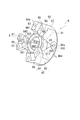
- FIG. 7 to 10 are views for explaining the first case portion 6.
- FIG. 7 is a perspective view of the first case portion 6 as viewed from the second case portion 7 side.
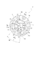
- FIG. 8 is a plan view of the first case portion 6 as viewed from the second case portion 7 side.
- FIG. 9 is a schematic view of a cross section taken along the line AA in FIG.
- FIG. 9 shows the arrangement of the pinion mate shaft 51 and the pinion mate gear 52 with virtual lines.
- FIG. 10 is a schematic view of a cross section taken along the line AA in FIG. In FIG. 10, the arrangement of the side gear 54A, the stepped pinion gear 43, and the drive shaft 9A is shown by a virtual line while omitting the illustration of the connecting beam 62 on the back side of the paper.
- the first case portion 6 has a ring-shaped base portion 61.
- the base portion 61 is a plate-shaped member having a thickness W61 in the rotation axis X direction.
- an opening 60 is provided in the central portion of the base portion 61.
- a tubular wall portion 611 surrounding the opening 60 is provided on the surface of the base portion 61 opposite to the second case portion 7 (on the right side in the drawing). The outer circumference of the tubular wall portion 611 is supported by a plate member 8 via a bearing B3 (see FIG. 2).
- Three connecting beams 62 extending to the second case portion 7 side are provided on the surface of the base portion 61 on the second case portion 7 side (left side in the drawing).
- the connecting beams 62 are provided at equal intervals in the circumferential direction around the rotation axis X (see FIGS. 7 and 8).
- the connecting beam 62 has a base portion 63 orthogonal to the base portion 61 and a connecting portion 64 wider than the base portion 63.
- the tip surface 64a of the connecting portion 64 is a flat surface orthogonal to the rotation axis X.
- the tip surface 64a is provided with a support groove 65 for supporting the pinion mate shaft 51.
- the support groove 65 is formed in a straight line along the radius line L of the ring-shaped base portion 61 when viewed from the rotation axis X direction.
- the support groove 65 crosses the central portion of the connecting portion 64 in the circumferential direction around the rotation axis X from the inner diameter side to the outer diameter side.
- the support groove 65 has a semicircular shape along the outer diameter of the pinion mate shaft 51.
- An arc portion 641 is formed on the inner diameter side (rotation shaft X side) of the connecting portion 64 in a shape along the outer circumference of the pinion mate gear 52.
- the outer circumference of the pinion mate gear 52 is supported via the spherical washer 53.
- an oil groove 642 is provided in a direction along the radius line L described above. The oil groove 642 is provided in a range from the support groove 65 of the pinion mate shaft 51 to the gear support portion 66 fixed to the inner circumference of the connecting portion 64.
- the gear support portion 66 is connected to a boundary portion between the base portion 63 and the connecting portion 64.
- the gear support portion 66 is provided in a direction orthogonal to the rotation axis X.
- the gear support portion 66 has a through hole 660 in the central portion. As shown in FIG. 8, the outer circumference of the gear support portion 66 is connected to the inner circumference of the three connecting portions 64. In this state, the center of the through hole 660 is located on the rotation axis X.
- the gear support portion 66 is provided with a recess 661 surrounding the through hole 660 on the surface opposite to the base portion 61 (left side in the drawing).
- a ring-shaped washer 55 that supports the back surface of the side gear 54A is housed in the recess 661.
- a cylindrical wall portion 541 is provided on the back surface of the side gear 54A. The washer 55 is extrapolated to the cylinder wall portion 541.
- Oil grooves 662 are provided on the surface of the gear support portion 66 on the recess 661 side when viewed from the rotation axis X direction. Oil grooves 662 are provided at predetermined intervals in the circumferential direction around the rotation axis X. The oil groove 662 extends from the inner circumference to the outer circumference of the gear support portion 66 along the radius line L described above. The oil groove 662 communicates with the oil groove 642 on the arc portion 641 side described above.
- a support hole 61a of the pinion shaft 44 is opened in the base portion 61.
- the support holes 61a are open in the region between the connecting beams 62, 62 arranged at intervals in the circumferential direction around the rotation axis X.
- the base portion 61 is provided with a boss portion 616 that surrounds the support hole 61a.
- a washer Wc (see FIG. 10) extrapolated to the pinion shaft 44 comes into contact with the boss portion 616 from the rotation axis X direction.
- an oil groove 617 is provided in a range from the central opening 60 to the boss portion 616.
- the oil groove 617 is formed in a tapered shape in which the width in the circumferential direction around the rotation axis X becomes narrower as it approaches the boss portion 616.
- the oil groove 617 is in contact with the oil groove 618 provided in the boss portion 616.
- bolt holes 67 and 67 are provided on both sides of the support groove 65.
- a connecting portion 74 on the side of the second case portion 7 is joined to the connecting portion 64 of the first case portion 6 from the rotation axis X direction.
- bolts B penetrating the connecting portion 74 on the second case portion 7 side are screwed into the bolt holes 67 and 67 and joined to each other.
- FIG. 11 to 16 are views for explaining the second case portion 7.
- FIG. 11 is a perspective view of the second case portion 7 as viewed from the first case portion 6 side.
- FIG. 12 is a plan view of the second case portion 7 as viewed from the first case portion 6 side.
- FIG. 13 is a schematic view of a cross section taken along the line AA in FIG.
- FIG. 13 shows the arrangement of the pinion mate shaft 51 and the pinion mate gear 52 by a virtual line.
- FIG. 14 is a schematic view of a cross section taken along the line AA in FIG. In FIG. 14, the arrangement of the side gear 54B, the stepped pinion gear 43, and the drive shaft 9B is shown by a virtual line while omitting the illustration of the connecting portion 74 on the back side of the paper.
- FIG. 15 is a perspective view of the second case portion 7 as viewed from the side opposite to the first case portion 6.
- FIG. 16 is a plan view of the second case portion 7 as viewed from the side opposite to
- the second case portion 7 has a ring-shaped base portion 71.
- the base portion 71 is a plate-shaped member having a thickness W71 in the rotation axis X direction.
- a through hole 70 that penetrates the base portion 71 in the thickness direction is provided in the central portion of the base portion 71.
- a protrusion 73a protruding toward the rotation axis X side is provided.
- the protrusion 73a is provided over the entire circumference in the circumferential direction around the rotation axis X.
- three support holes 71a of the pinion shaft 44 are opened on the outer diameter side of the peripheral wall portion 73.
- the support holes 71a are provided at predetermined intervals in the circumferential direction around the rotation axis X.
- On the inner diameter side of the peripheral wall portion 73 three slits 710 that penetrate the base portion 71 in the thickness direction are provided.
- the slit 710 When viewed from the rotation axis X direction, the slit 710 has an arc shape along the inner circumference of the peripheral wall portion 73.
- the slit 710 is formed in a predetermined angle range in the circumferential direction around the rotation axis X.
- the slits 710 are provided at predetermined intervals in the circumferential direction around the rotation axis X. Each of the slits 710 is provided across the inner diameter side of the support hole 71a in the circumferential direction around the rotation axis X.
- Three protruding walls 711 protruding toward the front side of the paper surface are provided between the slits 710 and 710 adjacent to each other in the circumferential direction around the rotation axis.
- the protruding wall 711 extends linearly in the radial direction of the rotation axis X.
- the protruding wall 711 is provided so as to straddle the peripheral wall portion 73 on the outer diameter side and the tubular wall portion 72 on the inner diameter side.
- the protruding walls 711 are provided at predetermined intervals in the circumferential direction around the rotation axis X.
- the protruding wall 711 is provided with the slit 710 having a phase shift of about 45 degrees in the circumferential direction around the rotation axis X.
- bolt accommodating portions 76, 76 recessed on the inner side of the paper surface are provided between the support holes 71a, 71a adjacent to each other in the circumferential direction around the rotation axis X. These bolt accommodating portions 76, 76 are provided in a symmetrical positional relationship with a radius line L in between.
- the bolt accommodating portion 76 is open to the outer circumference 71c of the base portion 71.
- a bolt insertion hole 77 is opened inside the bolt accommodating portion 76. The insertion hole 77 penetrates the base 71 in the thickness direction (rotation axis X direction).
- three connecting portions 74 projecting to the first case portion 6 side are provided on the surface of the base portion 71 on the first case portion 6 side (right side in the drawing).
- the connecting portions 74 are provided at equal intervals in the circumferential direction around the rotation axis X.
- the connecting portion 74 is formed with a width W7 in the same circumferential direction as the connecting portion 64 on the first case portion 6 side.
- the tip surface 74a of the connecting portion 74 is a flat surface orthogonal to the rotation axis X.
- the tip surface 74a is provided with a support groove 75 for supporting the pinion mate shaft 51.
- the support groove 75 is formed linearly along the radius line L of the base 71 when viewed from the rotation axis X direction.
- the support groove 75 is formed so as to cross the connecting portion 74 from the inner diameter side to the outer diameter side.
- the support groove 75 has a semicircular shape along the outer diameter of the pinion mate shaft 51.
- An arc portion 741 along the outer circumference of the pinion mate gear 52 is provided on the inner diameter side (rotation shaft X side) of the connecting portion 74.
- the outer circumference of the pinion mate gear 52 is supported via the spherical washer 53 (see FIGS. 13 and 14).
- the oil groove 742 is provided in the direction along the radius line L described above.
- the oil groove 742 is provided in a range from the support groove 75 of the pinion mate shaft 51 to the base portion 71 located on the inner circumference of the connecting portion 74.
- the oil groove 742 communicates with the oil groove 712 provided on the surface 71b of the base 71.
- the oil groove 712 is provided along the radius line L when viewed from the rotation axis X direction, and is formed up to the through hole 70 provided in the base portion 71.
- a ring-shaped washer 55 that supports the back surface of the side gear 54B is placed on the surface 71b of the base portion 71.
- a cylindrical wall portion 540 is provided on the back surface of the side gear 54B. The washer 55 is extrapolated to the cylinder wall portion 540.
- An oil groove 721 is formed at a position intersecting the oil groove 712 on the inner circumference of the tubular wall portion 72 surrounding the through hole 70. On the inner circumference of the cylinder wall portion 72, an oil groove 721 is provided along the rotation axis X over the entire length of the cylinder wall portion 72 in the rotation axis X direction.
- a guide portion 78 is provided between the connecting portions 74 and 74 adjacent to each other in the circumferential direction around the rotation axis X.
- the guide portion 78 projects toward the first case portion 6 side (front side of the paper surface).
- the guide portion 78 has a tubular shape when viewed from the rotation axis X direction.
- the guide portion 78 surrounds the support hole 71a provided in the base portion 71.
- the outer peripheral portion of the guide portion 78 is cut along the outer peripheral portion 71c of the base portion 71.
- the pinion shaft 44 is inserted into the support hole 71a of the guide portion 78 from the side of the first case portion 6 in the cross-sectional view along the axis X1.
- the pinion shaft 44 is positioned in a state where rotation around the axis X1 is restricted by the positioning pin P. In this state, the small-diameter gear portion 432 of the stepped pinion gear 43 extrapolated to the pinion shaft 44 is in contact with the guide portion 78 from the axis X1 direction with the washer Wc sandwiched between them.
- the bearing B2 is extrapolated to the cylinder wall portion 72 of the second case portion 7.
- the bearing B2 extrapolated to the cylinder wall portion 72 is held by the support portion 145 of the fourth box 14.
- the tubular wall portion 72 of the differential case 50 is rotatably supported by the fourth box 14 via the bearing B2.
- a drive shaft 9B penetrating the opening 145a of the fourth box 14 is inserted into the support portion 145 from the rotation axis X direction.
- the drive shaft 9B is rotatably supported by the support portion 145.
- a lip seal RS is fixed to the inner circumference of the opening 145a.
- a lip portion (not shown) of the lip seal RS is elastically in contact with the outer circumference of the cylinder wall portion 540 of the side gear 54B extrapolated to the drive shaft 9B. As a result, the gap between the outer circumference of the cylinder wall portion 540 of the side gear 54B and the inner circumference of the opening 145a is sealed.
- the first case portion 6 of the differential case 50 is supported by the plate member 8 via the bearing B3 extrapolated to the cylinder wall portion 611 (see FIG. 2).
- a drive shaft 9A penetrating the insertion hole 130a of the third box 13 is inserted from the direction of the rotation axis.
- the drive shaft 9A is provided across the motor shaft 20 of the motor 2 and the inner diameter side of the sun gear 41 of the planetary reduction gear 4 in the rotation axis X direction.
- side gears 54A and 54B are spline-fitted on the outer periphery of the tip of the drive shaft 9 (9A, 9B).
- the side gears 54A and 54B and the drive shafts 9 (9A and 9B) are integrally rotatably connected around the rotation shaft X.
- the side gears 54A and 54B are arranged to face each other at intervals in the rotation axis X direction.
- the connecting portion 510 of the pinion mate shaft 51 is located between the side gears 54A and 54B.
- a total of three pinion mate shafts 51 extend radially outward from the connecting portion 510.
- a pinion mate gear 52 is supported on each of the pinion mate shafts 51.
- the pinion mate gear 52 is assembled to the side gear 54A located on one side in the rotation axis X direction and the side gear 54B located on the other side in a state where the teeth are meshed with each other.
- the lubricating oil OL is stored inside the fourth box 14.
- the lower side of the differential case 50 is located in the stored oil OL.
- the oil OL is stored up to the height at which the connecting beam 62 is located in the oil OL.
- the stored oil OL is scraped up by the differential case 50 that rotates around the rotation axis X when the output rotation of the motor 2 is transmitted.
- FIG. 17 to 25 are views for explaining the oil catch portion 15.
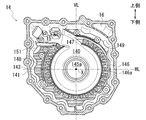
- FIG. 17 is a plan view of the fourth box 14 as viewed from the third box 13 side.
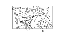
- FIG. 18 is a perspective view of the oil catch portion 15 shown in FIG. 17 as viewed from diagonally above.
- FIG. 19 is a plan view of the fourth box 14 as viewed from the third box 13 side.
- FIG. 19 shows a state in which the differential case 50 is arranged.
- FIG. 20 is a perspective view of the oil catch portion 15 shown in FIG. 19 as viewed from diagonally above.
- FIG. 21 is a cross-sectional view taken along the line AA in FIG. FIG.
- FIG. 22 is a schematic view illustrating the positional relationship between the oil catch portion 15 and the differential case 50 (first case portion 6, second case portion 7) when the power transmission device 1 is viewed from above.
- FIG. 23 is a view of the catch portion 153 as viewed from above.
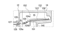
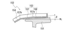
- FIG. 24 is a cross-sectional view taken along the line AA of FIG. 23, and is a diagram for explaining the inclination of the inclined portion 156.
- FIG. 25 is a cross-sectional view taken along the line BB of FIG. 23, and is a diagram for explaining the inclination of the inclined portion 157.
- the inclinations of the inclined portion 156 and the inclined portion 157 are exaggerated, and the portions other than the inclined portion are appropriately omitted.
- hatching is added to clarify the positions of the joint portion 142 of the fourth box 14 and the support wall portion 146.
- the fourth box 14 when viewed from the rotation axis X direction is provided with support wall portions 146 that surround the central opening 145a at predetermined intervals.
- the inside of the support wall portion 146 (rotation axis X) is the accommodating portion 140 of the differential case 50 (see FIG. 19).
- a space for the oil catch portion 15 and a space for the breather chamber 16 are formed in the fourth box 14 above the horizontal line HL passing through the rotation axis X.
- the horizon HL is a horizon HL based on the installation state of the power transmission device 1 in the vehicle.
- the horizontal line HL when viewed from the rotation axis X direction is orthogonal to the rotation axis X.
- a communication port 147 for communicating the oil catch portion 15 and the accommodating portion 140 of the differential case 50 is provided in the region intersecting the vertical line VL.
- the communication port 147 is formed as a notch in the support wall portion 146 as the ring gear support portion.
- the oil catch portion 15 and the breather chamber 16 are located on one side (left side in the figure) and the other side (right side in the figure) with a vertical line VL orthogonal to the rotation axis X, respectively. doing.
- the oil catch portion 15 is arranged at a position offset from the vertical line VL passing through the rotation center (rotation axis X) of the differential case 50.
- the vertical line VL is a vertical line VL based on the installation state of the power transmission device 1 in the vehicle.
- the vertical line VL when viewed from the rotation axis X direction is orthogonal to the rotation axis X and the horizontal line HL.
- the oil catch portion 15 is formed so as to extend to the back side of the paper surface from the support wall portion 146.
- a support base portion 151 as a shelf portion is provided on the lower edge of the oil catch portion 15 so as to project toward the front side of the paper surface.
- the support base portion 151 is provided on the front side of the paper surface of the support wall portion 146 and in the range from the joint portion 142 of the fourth box 14 to the back side of the paper surface.
- a communication port 147 is formed on the vertical VL side (right side in the drawing) of the oil catch portion 15 when viewed from the rotation axis X direction by cutting out a part of the support wall portion 146. Will be done.
- the communication port 147 communicates the oil catch portion 15 with the accommodating portion 140 of the differential case 50.
- the support wall portion 146 has a C shape when viewed from the rotation axis X direction.
- the communication port 147 is provided in a range that crosses the vertical line VL from the breather chamber 16 side (right side in the figure) to the oil catch portion 15 side (left side in the figure) when viewed from the rotation axis X direction.
- the communication port 147 is provided at a position adjacent to the support base portion 151 provided on the oil catch portion 15 in the circumferential direction around the rotation axis X. As a result, the oil OL scraped up by the differential case 50 can easily enter the support base portion 151 from the communication port 147.
- the differential case 50 rotates in the counterclockwise direction CCW around the rotation axis X when viewed from the third box 13 side. .. Therefore, the oil catch portion 15 is located on the downstream side in the rotation direction of the differential case 50.
- the width of the communication port 147 in the circumferential direction is wider on the left side of the vertical line VL than on the right side.
- the left side of the vertical line VL is the downstream side in the rotation direction of the differential case 50, and the right side is the upstream side.
- the outer peripheral position of the rotary orbit of the second shaft portion 446 and the outer peripheral position of the rotary orbit of the large-diameter gear portion 431 are offset in the radial direction of the rotary shaft X.
- the outer peripheral position of the rotary orbit of the second shaft portion 446 is located on the inner diameter side of the outer peripheral position of the rotary orbit of the large-diameter gear portion 431. Therefore, there is a space margin on the outer diameter side of the second shaft portion 446. By using this space and providing the oil catch portion 15, the space inside the main body box 10 can be effectively used.
- the second shaft portion 446 projects toward the back side of the small diameter gear portion 432 when viewed from the motor 2.
- the peripheral member of the second shaft portion 446 (for example, the guide portion 58 of the differential case 50 that supports the second shaft portion 446) is located close to the oil catch portion 15. Therefore, the oil OL (lubricating oil) can be smoothly supplied from the peripheral member to the oil catch portion 15.
- an oil hole 151a that opens upward is provided on the back side of the support base portion 151.
- the oil hole 151a extends from the outer diameter side end opened on the upper surface of the support base portion 151 to the inner diameter side in the fourth box 14.
- the inner diameter side end of the oil hole 151a is open to the inner circumference of the support portion 145.
- the end portion on the inner diameter side of the oil hole 151a is opened between the lip seal RS and the bearing B2.
- an oil guide 152 is placed on the support base portion 151.
- the oil guide 152 is provided on the upper part of the support base portion 151 (shelf portion) as a catch member for the oil OL.
- the oil guide 152 has a catch portion 153 and a guide portion 154 extending from the catch portion 153 to the first box 11 side (front side of the paper surface).
- the support base portion 151 is located on the radial outside of the rotation axis X at a position overlapping a part of the differential case 50 (first case portion 6, second case portion 7). It is provided so as to avoid interference with the attached pinion gear 43 (large diameter gear portion 431).
- the catch portion 153 is provided at a position overlapping the second shaft portion 446 of the pinion shaft 44 when viewed from the radial direction of the rotation shaft X.
- the guide portion 154 is provided at a position where it overlaps the first shaft portion 445 of the pinion shaft 44 and the large diameter gear portion 431.
- the catch portion 153 is composed of an inclined portion 156 as a second inclined surface and an inclined portion 157 as a first inclined surface.
- the inclined portion 156 is located on the back side (upper side in FIG. 22) of the support base portion 151 and is connected to the oil hole 151a.
- the inclined portion 157 is located on the front side (lower side in FIG. 22) of the support base portion 151 and is connected to the guide portion 154.
- the inclined portion 157 communicates with the inclined portion 156 at one end 157a.
- the inclined portion 156 extends from one end 156a connected to the oil hole 151a toward the other end 156b in a direction orthogonal to the rotation axis X. As shown in FIG. 24, the surface of the inclined portion 156 is inclined downward from the other end 156b toward one end 156a.
- the inclined portion 157 extends from one end 157a toward the other end 157b in a direction along the rotation axis X.
- One end 157a of the inclined portion 157 communicates with the inclined portion 156, and the other end 157b connects to the guide portion 154.
- the surface of the inclined portion 157 is inclined downward from one end 157a toward the other end 157b.
- a wall portion 153a is erected on the outer peripheral edge of the inclined portion 156 and the inclined portion 157 of the catch portion 153.
- the wall portion 153a extends in a direction away from the support base portion 151 (upward).
- a part of the oil OL caught by the catch portion 153 is held and stored in the oil guide 152 by the wall portion 153a.
- the surfaces of the inclined portion 156 and the inclined portion 157 are inclined respectively.
- a part of the oil OL caught by the inclined portion 156 flows toward the oil hole 151a according to gravity.
- a part of the oil OL caught by the inclined portion 157 flows toward the guide portion 154 according to gravity.
- a notch 155 is provided in the wall portion 153a extending from one end 156a of the inclined portion 156.
- the cutout portion 155 is provided in a region facing the oil hole 151a. A part of the oil OL flowing toward the oil hole 151a is discharged from the notch 155 toward the oil hole 151a. That is, the notch 155 guides the oil OL to the oil hole 151a as an introduction port.
- the inclination angle ⁇ of the inclined portion 156 with respect to the horizon HL is smaller than the inclination angle ⁇ of the inclined portion 157 with respect to the horizon HL. That is, the inclined portion 156 has a gentler inclination than the inclined portion 157.
- the opening area of the oil hole 151a is smaller than the area of the guide portion 154. Therefore, the amount of oil discharged from the oil hole 151a is smaller than that of the guide portion 154. Therefore, in the embodiment, the inclination of the inclined portion 156 connected to the oil hole 151a is made gentle to suppress the amount of oil OL flowing through the oil hole 151a.
- the guide portion 154 is inclined downward as the distance from the catch portion 153 increases.
- wall portions 154a and 154a are provided on both sides of the guide portion 154 in the width direction.
- the wall portions 154a and 154a are provided over the entire length of the guide portion 154 in the longitudinal direction.
- the wall portions 154a and 154a are connected to the wall portion 153a surrounding the outer circumference of the catch portion 153.
- a part of the oil OL stored in the inclined portion 157 of the catch portion 153 is discharged to the guide portion 154 side. That is, the guide portion 154 branches a part of the oil OL stored in the catch portion 153 as a branch port and guides the oil OL to a location other than the oil hole 151a.
- the guide portion 154 extends toward the second box 12 side at a position where it avoids interference with the differential case 50.
- the tip 154b of the guide portion 154 faces the through hole 126a provided in the wall portion 120 of the second box 12 with a gap in the rotation axis X direction.
- a boss portion 126 surrounding the through hole 126a is provided on the outer periphery of the wall portion 120.
- One end of the pipe 127 is fitted into the boss portion 126 from the rotation axis X direction.
- the pipe 127 passes through the outside of the second box 12 and extends to the third box 13.
- the other end of the pipe 127 communicates with an oil hole 136a (see FIG. 2) provided in the cylindrical connecting wall 136 of the third box 13.
- the oil OL is supplied to the internal space Sc of the connecting wall 136 through the guide portion 154 and the pipe 127.
- the third box 13 is provided with a radial oil passage 137 communicating with the internal space Sc.
- the radial oil passage 137 extends radially downward from the internal space Sc.
- the radial oil passage 137 communicates with the axial oil passage 138 provided in the joint portion 132.
- the axial oil passage 138 communicates with the oil reservoir 128 provided at the lower part of the second box 12 via the communication hole 112a provided at the joint portion 112 of the first box 11.
- the oil sump portion 128 penetrates the inside of the peripheral wall portion 121 in the rotation axis X direction.
- the oil sump 128 communicates with the second gear chamber Sb2 provided in the fourth box 14.
- the operation of the power transmission device 1 having such a configuration will be described.
- the planetary reduction gear 4, the differential mechanism 5, and the drive shafts 9 (9A, 9B) are provided along the transmission path of the output rotation of the motor 2. ing.
- the sun gear 41 is an input unit for the output rotation of the motor 2.
- the differential case 50 that supports the stepped pinion gear 43 serves as an output unit for the input rotation.
- the stepped pinion gear 43 (large diameter gear portion 431, small diameter gear portion 432) rotates around the axis X1 by the rotation input from the sun gear 41 side.
- the small-diameter gear portion 432 of the stepped pinion gear 43 meshes with the ring gear 42 fixed to the inner circumference of the fourth box 14. Therefore, the stepped pinion gear 43 revolves around the rotation axis X while rotating around the axis X1.
- the rotation shaft X is the center of revolution of the stepped pinion gear 43 (pinion gear).
- the outer diameter R2 of the small-diameter gear portion 432 of the stepped pinion gear 43 is smaller than the outer diameter R1 of the large-diameter gear portion 431 (see FIG. 3).
- the differential case 50 first case portion 6, second case portion 7) that supports the stepped pinion gear 43 rotates around the rotation axis X at a rotation speed lower than the rotation input from the motor 2 side. Therefore, the rotation input to the sun gear 41 of the planetary reduction gear 4 is greatly reduced by the stepped pinion gear 43. The reduced rotation is output to the differential case 50 (differential mechanism 5).
- the lubricating oil OL is stored inside the fourth box 14. Therefore, the stored oil OL is scraped up by the differential case 50 that rotates around the rotation axis X when the output rotation of the motor 2 is transmitted. Due to the oil OL scraped up, the meshing portion between the sun gear 41 and the large diameter gear portion 431, the meshing portion between the small diameter gear portion 432 and the ring gear 42, and the meshing portion between the pinion mate gear 52 and the side gears 54A and 54B. Is lubricated.
- the differential case 50 rotates in the counterclockwise direction CCW around the rotation axis X when viewed from the third box 13 side.
- An oil catch portion 15 is provided on the upper portion of the fourth box 14.
- the oil catch portion 15 is located on the downstream side in the rotation direction of the differential case 50. Most of the oil OL scraped up by the differential case 50 flows into the oil catch portion 15.
- an oil guide 152 mounted on the support base portion 151 is provided in the oil catch portion 15.
- the guide portion 154 and the catch portion 153 of the oil guide 152 are located on the radial outside of the first case portion 6 of the differential case 50 and on the radial outside of the second case portion 7 of the differential case 50. Therefore, most of the oil OL that has been scraped up by the differential case 50 and has flowed into the oil catch portion 15 is captured by the oil guide 152.
- a part of the oil OL captured by the inclined portion 156 of the oil guide 152 flows to the oil hole 151a side along the inclination.
- the oil OL is discharged from the notch 155 provided in the wall portion 153a and flows into the oil hole 151a having one end opened on the upper surface of the support base portion 151.
- the inner diameter side end of the oil hole 151a is open to the inner circumference of the support portion 145 (see FIG. 2). Therefore, the oil OL that has flowed into the oil hole 151a is discharged into the gap Rx between the inner circumference of the support portion 145 of the fourth box 14 and the cylinder wall portion 540 of the side gear 54B.
- the oil OL that lubricates the bearing B2 moves to the outer diameter side by the centrifugal force due to the rotation of the differential case 50.
- a slit 710 is provided along the inner circumference of the peripheral wall portion 73. Further movement of the oil OL to the outer diameter side is hindered by the peripheral wall portion 73.
- the oil OL passes through the slit 710 toward the first case portion 6 side.
- the oil passage 781 in the case is open on the inner circumference of the guide portion 78.
- a part of the oil OL that has passed through the slit 710 flows into the oil passage 781 in the case due to the centrifugal force generated by the rotation of the differential case 50.
- the oil OL that has flowed into the oil passage 781 in the case flows into the in-shaft oil passage 440 of the pinion shaft 44 through the introduction passage 441.
- the oil OL that has flowed into the in-shaft oil passage 440 is discharged radially outward from the oil holes 442 and 443.
- the discharged oil OL lubricates the needle bearing NB extrapolated to the pinion shaft 44.
- a part of the oil OL discharged into the gap Rx passes through the oil groove 721 provided on the inner circumference of the cylinder wall portion 72 of the second case portion 7, as shown in FIGS. 13 and 14.
- the oil OL that has passed through the oil groove 721 is supplied to the washer 55 that supports the back surface of the side gear 54B to lubricate the washer 55.
- the oil OL passes through the oil groove 712 provided in the base portion 71 of the second case portion 7 and the oil groove 742 provided in the arc portion 741.
- the oil OL that has passed through the oil groove 742 is supplied to the spherical washer 53 that supports the back surface of the pinion mate gear 52, and lubricates the spherical washer 53.
- the oil OL further flows along the inclination of the guide portion 154.
- the tip 154b of the guide portion 154 faces the through hole 126a provided in the wall portion 120 of the second box 12 with a gap in the rotation axis X direction. Therefore, most of the oil OL that has flowed into the guide portion 154 flows into the through hole 126a of the second box 12.
- a boss portion 126 surrounding the through hole 126a is provided on the outer periphery of the wall portion 120.
- One end of the pipe 127 is fitted into the boss portion 126 from the rotation axis X direction.
- the pipe 127 passes through the outside of the second box 12 and extends to the third box 13.
- the other end of the pipe 127 communicates with an oil hole 136a (see FIG. 2) provided in the cylindrical connecting wall 136 of the third box 13.
- a part of the oil OL that has reached the oil catch portion 15 is supplied to the internal space Sc of the connection wall 136 through the guide portion 154 and the pipe 127.
- the oil OL discharged from the oil hole 136a into the internal space Sc is stored in the internal space Sc.
- the oil OL also lubricates the bearing B4 supported by the peripheral wall portion 131 of the third box 13.
- a part of the oil OL discharged into the internal space Sc moves to the other end 20b side of the motor shaft 20 through the gap between the outer circumference of the drive shaft 9A and the inner circumference of the motor shaft 20.
- the other end 20b of the motor shaft 20 is inserted inside the tubular wall portion 541 of the side gear 54A.
- a connecting path 542 communicating with the back surface of the side gear 54A is provided on the inner circumference of the cylinder wall portion 541. Therefore, a part of the oil OL that has moved to the other end 20b side of the motor shaft 20 and has been discharged to the inside of the cylinder wall portion 541 passes through the connecting path 542.
- the oil OL that has passed through the connecting path 542 is supplied to the washer 55 on the back surface of the side gear 54A to lubricate the washer 55.
- the oil OL that lubricates the washer 55 on the back surface of the side gear 54A passes through the oil groove 662 provided in the gear support portion 66 of the first case portion 6 and the oil groove 642 provided in the arc portion 641.
- the oil OL that has passed through the oil groove 642 is supplied to the spherical washer 53 that supports the back surface of the pinion mate gear 52, and lubricates the spherical washer 53.
- the internal space Sc of the third box 13 includes a radial oil passage 137, an axial oil passage 138, a communication hole 112a, and an oil reservoir provided at the lower part of the second box 12. It communicates with the second gear chamber Sb2 provided in the fourth box 14 via 128. Therefore, the oil OL in the internal space Sc is held at the same height position as the oil OL stored in the fourth box 14.
- the oil OL in the fourth box 14 is scraped up when the drive wheels W and W rotate, and is used for lubrication of the bearing and the meshing portion between the gears.
- the oil OL used for lubrication is returned to the fourth box 14 so that it can be scraped up again.
- the power transmission device 1 has the following configuration.
- the power transmission device 1 includes a differential mechanism 5, a differential case 50 (case) accommodating the differential mechanism 5, and a stepped pinion gear 43 (pinion gear) supported by the differential case 50 in a fourth box. It is contained in 14 (box).
- the fourth box 14 has a support base portion 151 (shelf portion) above the horizontal line HL passing through the rotation axis X, which is the center of revolution of the stepped pinion gear 43.
- the oil OL scraped up by the rotation of the stepped pinion gear 43 is caught by the upper side of the support base portion 151, that is, the surface of the support base portion 151 or the oil guide 152 placed on the support base portion 151.
- the oil OL can be sent to various places from the upper side of the support base portion 151. That is, by providing the support base portion 151, the degree of freedom in the supply design of the oil OL scraped up by the rotation of the stepped pinion gear 43 can be increased.
- the support base portion 151 has an oil hole 151a that opens upward.
- the oil OL that has been scraped up by the rotation of the stepped pinion gear 43 and has fallen to the upper side of the support base portion 151 is introduced into the oil hole 151a that opens upward.
- This configuration can efficiently guide the oil OL to the oil hole 151a as compared with the configuration in which the scraped oil OL is introduced from the oil hole 151a opened laterally.
- the power transmission device 1 has an oil guide 152 (catch member) provided on the upper portion of the support base portion 151.
- the oil guide 152 is provided with a notch 155 (introduction port) for guiding the oil OL to the oil hole 151a.
- the oil guide 152 provided on the upper part of the support base 151 catches the oil OL, gravity is used to introduce the oil OL from the notch 155 into the oil hole 151a provided in the support base 151. With this configuration, the oil OL can be used efficiently.
- the notch portion 155 is provided as the introduction port, but the shape of the introduction port is not limited.
- the introduction port may be an oil hole provided on the bottom or side surface of the oil guide 152.
- the oil guide 152 is provided with a guide portion 154 (branch port) for guiding the oil OL to a location other than the oil hole 151a.
- the amount of oil OL that can pass through the oil hole 151a formed in the oil guide 152 is smaller than the capacity of the oil OL that can be caught by the oil guide 152. Therefore, the excess oil OL caught by the oil guide 152 is branched by the guide portion 154 and used for lubrication of another portion. With this configuration, the oil OL can be effectively used.
- the oil guide 152 has an inclined portion 157 (first inclined surface) connected to the guide portion 154 and an inclined portion 156 (second inclined surface) connected to the notch portion 155.
- the inclination angle ⁇ of the inclined portion 156 is smaller than the inclination angle ⁇ of the inclined portion 157.
- the oil OL flows according to gravity by the two inclined portions 156 and 157, the oil OL can be smoothly guided to the notch portion 155 and the guide portion 154 to which each of the inclined portions 156 and 157 is connected. Further, the inclination angle ⁇ of the inclined portion 156 connected to the notch portion 155 is made gentle with respect to the inclination angle ⁇ of the inclined portion 157. As a result, in the inclined portion 156, the oil OL does not immediately flow to the notch portion 155, but is held in the inclined portion 156 for a certain period of time. With this configuration, the oil OL holding function in the catch portion 153 of the oil guide 152 can be enhanced.
- the power transmission device 1 has a ring gear 42 that meshes with the stepped pinion gear 43.
- the fourth box 14 has a support wall portion 146 (ring gear support portion) that meshes with the ring gear 42.
- the support wall portion 146 has a communication port 147 (notch) at a position adjacent to the support base portion 151 in the circumferential direction.
- the oil OL can be supplied to the support base portion 151 more smoothly. Specifically, a part of the oil OL scattered by the rotation of the stepped pinion gear 43 jumps over the outer peripheral side of the ring gear 42 and scatters in the direction toward the support base portion 151. The support wall portion 146 that meshes with the ring gear 42 can interfere with the oil OL toward the support base portion 151. Therefore, a communication port 147 is provided in the support wall portion 146 to guide the oil OL to the support base portion 151.
- forming the notch as the communication port 147 means that, in other words, the support wall portions 146 that mesh with the ring gear 42 are arranged on both sides of the notch. That is, the structure of the embodiment means that the stability of the support of the ring gear 42 is increased.
- the support wall portion 146 has a C-shaped shape.
- the support wall portion 146 may be composed of, for example, a plurality of individual support portions arranged on the outer periphery of the ring gear 42. However, as in the embodiment, the support wall portion 146 is formed in a C shape when viewed from the rotation axis X direction and surrounds the outer circumference of the ring gear 42, whereby the area of the portion that supports the ring gear 42 is formed. Can be increased. With this configuration, the support stability of the ring gear 42 can be increased.
- the power transmission device 1 has the following configuration.
- the power transmission device 1 includes a motor 2 arranged upstream of the transmission path of the rotational driving force of the sun gear 41 that meshes with the stepped pinion gear 43, and a drive shaft 9A (drive) connected to the differential mechanism 5. Axis) and.
- the drive shaft 9A penetrates the inner circumferences of the sun gear 41 and the motor 2.
- the power transmission device 1 is a power transmission device for a single-axis electric vehicle, and can provide a compact power transmission device.
Landscapes
- Engineering & Computer Science (AREA)
- General Engineering & Computer Science (AREA)
- Mechanical Engineering (AREA)
- Chemical & Material Sciences (AREA)
- Combustion & Propulsion (AREA)
- Transportation (AREA)
- General Details Of Gearings (AREA)
Abstract
Description
差動機構と、
前記差動機構を収容するケースと、
前記ケースに支持されたピニオンギアと、をボックス内に有し、
前記ボックスは、前記ピニオンギアの公転中心を通る水平線よりも上方に棚部を有する。
図1は、本実施形態にかかる動力伝達装置1を説明するスケルトン図である。
図2は、本実施形態にかかる動力伝達装置1を説明する断面の模式図である。
図3は、動力伝達装置1の遊星減速ギア4周りの拡大図である。
図4は、動力伝達装置1の差動機構5周りの拡大図である。
動力伝達装置1では、モータ2の回転軸X回りの出力回転の伝達経路に沿って、パークロック機構3と、遊星減速ギア4と、差動機構5と、ドライブシャフト9(9A、9B)と、が設けられている。ドライブシャフト9(9A、9B)の軸線は、モータ2の回転軸Xと同軸である。
ここで、遊星減速ギア4は、モータ2の下流に接続されており、差動機構5は、遊星減速ギア4の下流に接続されており、ドライブシャフト9(9A、9B)は、差動機構5の下流に接続されている。
第1ボックス11は、支持壁部111をモータ2の回転軸Xに沿わせた向きで設けられている。支持壁部111の内側には、モータ2が収容される。
周壁部121は、第1ボックス11の支持壁部111に外挿可能な内径で形成されている。
第1ボックス11と第2ボックス12は、第1ボックス11の支持壁部111に、第2ボックス12の周壁部121を外挿して互いに組み付けられている。
第1ボックス11では、支持壁部111の外周に複数の凹溝111bが設けられている。複数の凹溝111bは、回転軸X方向に間隔をあけて設けられている。凹溝111bの各々は、回転軸X周りの周方向の全周に亘って設けられている。
第1ボックス11の支持壁部111に、第2ボックス12の周壁部121が外挿される。凹溝111bの開口が周壁部121で閉じられている。支持壁部111と周壁部121との間に、冷却水が通流する複数の冷却路CPが形成される。
これらシールリング113は、支持壁部111に外挿された周壁部121の内周に圧接して、支持壁部111の外周と、周壁部121の内周との間の隙間を封止する。
壁部120では、モータ2側(図中、右側)の面に、開口120aを囲む筒状のモータ支持部125が設けられている。
モータ支持部125は、後記するコイルエンド253bの内側に挿入されている。モータ支持部125は、ロータコア21の端部21bに回転軸X方向の隙間をあけて対向している。
この径方向の厚みが厚い領域には、回転軸X方向に貫通してオイル溜り部128が設けられている。
オイル溜り部128は、連通孔112aを介して、第3ボックス13の接合部132に設けた軸方向油路138に連絡している。連通孔112aは、第1ボックス11の接合部112に設けられている。
第1ボックス11から見て第3ボックス13は、差動機構5とは反対側(図中、右側)に位置している。第3ボックス13の接合部132は、第1ボックス11の接合部112に回転軸X方向から接合されている。第3ボックス13と第1ボックス11は、ボルト(図示せず)で互いに連結されている。この状態において第1ボックス11は、支持壁部111の接合部122側(図中、右側)の開口が、第3ボックス13で塞がれている。
挿通孔130aの内周には、リップシールRSが設けられている。リップシールRSは、図示しないリップ部をドライブシャフト9Aの外周に弾発的に接触させている。挿通孔130aの内周と、ドライブシャフト9Aの外周との隙間が、リップシールRSにより封止されている。
壁部130における第1ボックス11側(図中、左側)の面には、挿通孔130aを囲む周壁部131が設けられている。周壁部131の内周には、ドライブシャフト9AがベアリングB4を介して支持されている。
モータ支持部135の外周には、円筒状の接続壁136が接続されている。接続壁136は、壁部130側(図中、右側)の周壁部131よりも大きい外径で形成されている。接続壁136は、回転軸Xに沿う向きで設けられており、モータ2から離れる方向に延びている。接続壁136は、モータ支持部135と第3ボックス13の壁部130とを接続している。
モータ支持部135の内周には、ベアリングB1が支持されている。モータシャフト20の外周が、ベアリングB1を介してモータ支持部135で支持されている。
ベアリングB1と隣り合う位置には、リップシールRSが設けられている。
第4ボックス14は、第2ボックス12から見て差動機構5側(図中、左側)に位置している。第4ボックス14の接合部142は、第2ボックス12の接合部123に回転軸X方向から接合されている。第4ボックス14と第2ボックス12は、ボルト(図示せず)で互いに連結されている。
モータ室Saは、第1ボックス11の内側で、第2ボックス12の壁部120と、第3ボックス13の壁部130との間に形成されている。
ギア室Sbは、第4ボックス14の内径側で、第2ボックス12の壁部120と、第4ボックス14の周壁部141との間に形成されている。
プレート部材8は、第4ボックス14に固定されている。
プレート部材8は、ギア室Sbを、遊星減速ギア4と差動機構5を収容する第1ギア室Sb1と、パークロック機構3を収容する第2ギア室Sb2とに区画している。
回転軸X方向において第2ギア室Sb2は、第1ギア室Sb1と、モータ室Saとの間に位置している。
ロータコア21から見てモータシャフト20の一端20a側(図中、右側)に位置するベアリングB1は、第3ボックス13のモータ支持部135の内周に支持されている。他端20b側に位置するベアリングB1は、第2ボックス12の円筒状のモータ支持部125の内周に支持されている。
モータシャフト20の回転軸X方向から見て、珪素鋼板はリング状を成している。珪素鋼板の外周側では、図示しないN極とS極の磁石が、回転軸X周りの周方向に交互に設けられている。
電磁鋼板の各々は、支持壁部111の内周に固定されたリング状のヨーク部251と、ヨーク部251の内周からロータコア21側に突出するティース部252と、を有している。
モータシャフト20の他端20bは、第4ボックス14の内側で、後記するサイドギア54Aに、回転軸X方向の隙間をあけて対向している。
リップシールRSは、モータ2を収容するモータ室Saと、第4ボックス14内のギア室Sbとを区画している。
リップシールRSは、モータ室SaへのオイルOLの流入を阻止するために設けられている。
嵌合部202の外周には、パークギア30とサンギア41がスプライン嵌合している。
基部410の他端410bには、モータシャフト20の他端20bに螺合したナットNが、回転軸X方向から圧接している。
サンギア41とパークギア30は、ナットNと段部201との間に挟み込まれた状態で、モータシャフト20に対して相対回転不能に設けられている。
段付きピニオンギア43は、大径歯車部431と小径歯車部432が、回転軸Xに平行な軸線X1方向で並んで、一体に設けられたギア部品である。
大径歯車部431は、小径歯車部432の外径R2よりも大きい外径R1で形成されている。
段付きピニオンギア43は、軸線X1に沿う向きで設けられている。この状態において、大径歯車部431はモータ2側(図中、右側)に位置している。
リングギア42は、外周に設けた係合歯421を、第4ボックス14の支持壁部146に設けた歯部146aにスプライン嵌合している。リングギア42は、リングギア支持部としての支持壁部146に噛合うことによって、回転軸X回りの回転が規制されている。
段付きピニオンギア43は、貫通孔430を貫通したピニオン軸44の外周で、ニードルベアリングNB、NBを介して回転可能に支持されている。
ピニオン軸44には、軸内油路440とピニオン軸44の外周とを連通させる油孔442、443が設けられている。
油孔442は、小径歯車部432の内周を支持するニードルベアリングNBが設けられた領域に開口している。
ピニオン軸44において油孔443、442は、段付きピニオンギア43が外挿された領域内に開口している。
ピニオン軸44の外周において導入路441は、後記する第2ケース部7の支持孔71a内に位置する領域に開口している。導入路441は、軸内油路440とピニオン軸44の外周とを連通させている。
軸線X1に沿う断面視においてケース内油路781は、軸線X1に対して傾斜している。ケース内油路781は、回転軸X側に向かうにつれて、基部71に設けたスリット710に近づく向きで傾斜している。
ケース内油路781から導入路441に流入したオイルOLは、ピニオン軸44の軸内油路440に流入する。軸内油路440に流入したオイルOLは、油孔442、443から径方向外側に排出される。油孔442、443から排出されたオイルOLは、ピニオン軸44に外挿されたニードルベアリングNBを潤滑する。
ピニオン軸44は、貫通孔444と、後記する第2ケース部7側の挿入穴782との軸線X1回りの位相を合わせて設けられている。挿入穴782に挿入された位置決めピンPが、ピニオン軸44の貫通孔444を貫通する。これによって、ピニオン軸44は、軸線X1回りの回転が規制された状態で、第2ケース部7側で支持される。
ピニオン軸44の長手方向の他端44b側では、段付きピニオンギア43から突出した領域が第2軸部446となっている。第2軸部446は、デフケース50の第2ケース部7に設けた支持孔71aで支持されている。
ピニオン軸44では、第1軸部445よりも第2軸部446のほうが、軸線X1方向の長さが長くなっている。
図5は、差動機構5のデフケース50周りの斜視図である。
図6は、差動機構5のデフケース50周りの分解斜視図である。
図4から図6に示すように、ケースとしてのデフケース50は、差動機構5を収容する。デフケース50は、第1ケース部6と第2ケース部7を回転軸X方向で組み付けて形成される。本実施形態では、デフケース50の第1ケース部6と第2ケース部7が、遊星減速ギア4のピニオン軸44を支持するキャリアとしての機能を有している。
ピニオンメートシャフト51は、回転軸X周りの周方向に等間隔で設けられている(図6参照)。
ピニオンメートシャフト51の各々の内径側の端部は、共通の連結部510に連結されている。
この状態においてピニオンメートギア52の各々は、ピニオンメートシャフト51で回転可能に支持されている。
サイドギア54Aは、回転軸X方向における一方側から、3つのピニオンメートギア52に噛合している。サイドギア54Bは、回転軸X方向における他方側から、3つのピニオンメートギア52に噛合している。
図7は、第1ケース部6を第2ケース部7側から見た斜視図である。
図8は、第1ケース部6を第2ケース部7側から見た平面図である。
図9は、図8におけるA-A断面の模式図である。図9は、ピニオンメートシャフト51とピニオンメートギア52の配置を仮想線で示している。
図10は、図8におけるA-A断面の模式図である。図10は、紙面奥側の連結梁62の図示を省略しつつ、サイドギア54Aと段付きピニオンギア43とドライブシャフト9Aの配置を仮想線で示している。
図9および図10に示すように、基部61の中央部には、開口60が設けられている。基部61における第2ケース部7とは反対側(図中、右側)の面には、開口60を囲む筒壁部611が設けられている。筒壁部611の外周は、ベアリングB3を介して、プレート部材8で支持されている(図2参照)。
連結梁62は、回転軸X周りの周方向に、等間隔で設けられている(図7および図8参照)。
連結梁62は、基部61に対して直交する基部63と、基部63よりも幅広の連結部64と、を有している。
図9および図10に示すように、支持溝65は、ピニオンメートシャフト51の外径に沿う半円形を成している。支持溝65は、円柱状のピニオンメートシャフト51の半分を収容可能な深さで形成されている。すなわち、支持溝65は、ピニオンメートシャフト51の直径Daの半分(=Da/2)に相当する深さで形成されている。
円弧部641では、ピニオンメートギア52の外周が、球面状ワッシャ53を介して支持される。
円弧部641では、前記した半径線Lに沿う向きで油溝642が設けられている。油溝642は、ピニオンメートシャフト51の支持溝65から、連結部64の内周に固定されたギア支持部66までの範囲に設けられている。
図8に示すように、ギア支持部66の外周は、3つの連結部64の内周に接続されている。この状態において貫通孔660の中心は、回転軸X上に位置している。
サイドギア54Aの裏面には、円筒状の筒壁部541が設けられている。ワッシャ55は筒壁部541に外挿されている。
油溝662は、前記した半径線Lに沿って、ギア支持部66の内周から外周まで及んでいる。油溝662は、前記した円弧部641側の油溝642に連絡している。
基部61には、支持孔61aを囲むボス部616が設けられている。ボス部616には、ピニオン軸44に外挿されたワッシャWc(図10参照)が、回転軸X方向から接触する。
図8に示すように、油溝617は、ボス部616に近づくにつれて、回転軸X周りの周方向の幅が狭くなる先細り形状で形成されている。油溝617は、ボス部616に設けた油溝618に連絡している。
第1ケース部6の連結部64には、第2ケース部7側の連結部74が回転軸X方向から接合される。第1ケース部6と第2ケース部7は、第2ケース部7側の連結部74を貫通したボルトBが、ボルト穴67、67に螺入されて、互いに接合される。
図11は、第2ケース部7を第1ケース部6側から見た斜視図である。
図12は、第2ケース部7を第1ケース部6側から見た平面図である。
図13は、図12におけるA-A断面の模式図である。図13は、ピニオンメートシャフト51とピニオンメートギア52の配置を仮想線で示している。
図14は、図12におけるA-A断面の模式図である。図14は、紙面奥側の連結部74の図示を省略しつつ、サイドギア54Bと段付きピニオンギア43とドライブシャフト9Bの配置を仮想線で示している。
図15は、第2ケース部7を第1ケース部6とは反対側から見た斜視図である。
図16は、第2ケース部7を第1ケース部6とは反対側から見た平面図である。
基部71は、回転軸X方向に厚みW71を有する板状部材である。
基部71の中央部には、基部71を厚み方向に貫通する貫通孔70が設けられている。
基部71における第1ケース部6とは反対側(図中、左側)の面には、貫通孔70を囲む筒壁部72と、筒壁部72を所定間隔で囲む周壁部73が設けられている。
周壁部73の先端には、回転軸X側に突出する突起部73aが設けられている。突起部73aは、回転軸X周りの周方向の全周に亘って設けられている。
周壁部73の内径側には、基部71を厚み方向に貫通する3つのスリット710が設けられている。
回転軸X方向から見てスリット710は、周壁部73の内周に沿う弧状を成している。
スリット710は、回転軸X周りの周方向に所定の角度範囲で形成されている。
ボルト収容部76の内側には、ボルトの挿通孔77が開口している。挿通孔77は、基部71を厚み方向(回転軸X方向)に貫通している。
連結部74は、回転軸X周りの周方向に、等間隔で設けられている。連結部74は、第1ケース部6側の連結部64と同じ周方向の幅W7で形成されている。
図5に示すように、支持溝75は、ピニオンメートシャフト51の外径に沿う半円形を成している。
図13に示すように、支持溝75は、円柱状のピニオンメートシャフト51の半分を収容可能な深さで形成されている。すなわち、支持溝75は、ピニオンメートシャフト51の直径Daの半分(=Da/2)に相当する深さで形成されている。
円弧部741では、ピニオンメートギア52の外周が、球面状ワッシャ53を介して支持される(図13および図14参照)。
円弧部741では、前記した半径線Lに沿う向きで油溝742が設けられている。油溝742は、ピニオンメートシャフト51の支持溝75から、連結部74の内周に位置する基部71までの範囲に設けられている。
基部71の表面71bには、サイドギア54Bの裏面を支持するリング状のワッシャ55が載置される。サイドギア54Bの裏面には、円筒状の筒壁部540が設けられている。ワッシャ55は筒壁部540に外挿されている。
回転軸X方向から見て、ガイド部78は筒状を成している。ガイド部78は、基部71に設けた支持孔71aを囲んでいる。ガイド部78の外周部は、基部71の外周71cに沿って切除されている。
この状態において、ピニオン軸44に外挿された段付きピニオンギア43の小径歯車部432が、ワッシャWcを間に挟んで、軸線X1方向からガイド部78に当接している。
開口部145aの内周には、リップシールRSが固定されている。リップシールRSの図示しないリップ部が、ドライブシャフト9Bに外挿されたサイドギア54Bの筒壁部540の外周に弾発的に接触している。これにより、サイドギア54Bの筒壁部540の外周と開口部145aの内周との隙間が封止されている。
ドライブシャフト9Aは、モータ2のモータシャフト20と、遊星減速ギア4のサンギア41の内径側を回転軸X方向に横切って設けられている。
本実施形態では、合計3つのピニオンメートシャフト51が、連結部510から径方向外側に延びている。ピニオンメートシャフト51の各々に、ピニオンメートギア52が支持されている。ピニオンメートギア52は、回転軸X方向の一方側に位置するサイドギア54Aおよび他方側に位置するサイドギア54Bに、互いの歯部を噛合させた状態で組み付けられている。
本実施形態では、連結梁62が最も下部側に位置した際に、連結梁62がオイルOL内に位置する高さまで、オイルOLが貯留されている。
貯留されたオイルOLは、モータ2の出力回転の伝達時に、回転軸X回りに回転するデフケース50により掻き上げられる。
図17は、第4ボックス14を第3ボックス13側から見た平面図である。
図18は、図17に示したオイルキャッチ部15を斜め上方から見た斜視図である。
図19は、第4ボックス14を第3ボックス13側から見た平面図である。図19は、デフケース50を配置した状態を示している。
図20は、図19に示したオイルキャッチ部15を斜め上方から見た斜視図である。
図21は、図19におけるA-A断面図である。
図22は、動力伝達装置1を上方から見た場合におけるオイルキャッチ部15と、デフケース50(第1ケース部6、第2ケース部7)との位置関係を説明する模式図である。
図23は、キャッチ部153を上方から見た図である。
図24は、図23のA-A断面図であり、傾斜部156の傾斜を説明する図である。
図25は、図23のB-B断面図であり、傾斜部157の傾斜を説明する図である。図24および図25において、傾斜部156と傾斜部157の傾斜は誇張して示し、傾斜部以外の部分は適宜省略している。
尚、図17および図19では、第4ボックス14の接合部142と、支持壁部146の位置を明確にするために、ハッチングを付して示している。
第4ボックス14内の、回転軸Xを通る水平線HLよりも上方には、オイルキャッチ部15の空間と、ブリーザ室16の空間が形成されている。ここで、水平線HLは、動力伝達装置1の車両での設置状態を基準とした水平線HLである。回転軸X方向から見て水平線HLは、回転軸Xと直交している。
オイルキャッチ部15は、デフケース50の回転中心(回転軸X)を通る鉛直線VLからオフセットした位置に配置されている。図22に示すように、上方からオイルキャッチ部15を見ると、オイルキャッチ部15は、デフケース50の真上からオフセットした位置に配置されている。
ここで、鉛直線VLは、動力伝達装置1の車両での設置状態を基準とした鉛直線VLである。回転軸X方向から見て鉛直線VLは、回転軸Xおよび水平線HLと直交している。
回転軸X方向から見て連通口147は、鉛直線VLをブリーザ室16側(図中、右側)から、オイルキャッチ部15側(図中、左側)に横切る範囲に設けられている。
連通口147は、オイルキャッチ部15に設けられた支持台部151と、回転軸X周りの周方向に隣接する位置に設けられている。これにより、デフケース50で掻き上げられたオイルOLが、連通口147から支持台部151に入りやすくなっている。
そのため、オイルキャッチ部15は、デフケース50の回転方向における下流側に位置している。そして、連通口147の周方向の幅は、鉛直線VLを挟んだ左側のほうが、右側よりも広くなっている。鉛直線VLを挟んだ左側は、デフケース50の回転方向における下流側であり、右側は上流側である。これにより、回転軸X回りに回転するデフケース50で掻き上げられたオイルOLの多くが、オイルキャッチ部15内に流入できるようになっている。
よって、当該周辺部材からオイルキャッチ部15へのオイルOL(潤滑油)の供給をスムーズに行うことができる。
図2に示すように、支持部145において油孔151aの内径側の端部は、リップシールRSとベアリングB2との間に開口している。
回転軸Xの径方向から見て、キャッチ部153は、ピニオン軸44の第2軸部446と重なる位置に設けられている。さらにガイド部154は、ピニオン軸44の第1軸部445と大径歯車部431と重なる位置に設けられている。
傾斜部156および傾斜部157の表面には、それぞれ傾斜が付けられている。これによって、図22に示すように、傾斜部156でキャッチされたオイルOLの一部は、重力に従って油孔151aに向かって流れる。傾斜部157でキャッチされたオイルOLの一部は、重力に従ってガイド部154に向かって流れる。
切欠部155は、油孔151aに対向する領域に設けられている。油孔151aに向かって流れたオイルOLの一部は、切欠部155の部分から油孔151aに向けて排出される。すなわち、切欠部155は、導入口として、油孔151aにオイルOLを導く。
図23に示すように、キャッチ部153の傾斜部157に貯留されたオイルOLの一部は、ガイド部154側に排出される。すなわち、ガイド部154は、分岐口として、キャッチ部153に貯留されたオイルOLの一部を分岐させて、油孔151a以外の箇所へ導く。
壁部120の外周には、貫通孔126aを囲むボス部126が設けられている。ボス部126には、回転軸X方向から配管127の一端が嵌入している。
径方向油路137は、内部空間Scから径方向下側に延びる。径方向油路137は、接合部132内に設けた軸方向油路138に連通する。
オイル溜り部128は、周壁部121内を回転軸X方向に貫通している。オイル溜り部128は、第4ボックス14に設けた第2ギア室Sb2に連絡する。
図1に示すように、動力伝達装置1では、モータ2の出力回転の伝達経路に沿って、遊星減速ギア4と、差動機構5と、ドライブシャフト9(9A、9B)と、が設けられている。
ここで、段付きピニオンギア43の小径歯車部432は、第4ボックス14の内周に固定されたリングギア42に噛合している。そのため、段付きピニオンギア43は、軸線X1回りに自転しながら、回転軸X周りに公転する。回転軸Xは、段付きピニオンギア43(ピニオンギア)の公転中心である。
これにより、段付きピニオンギア43を支持するデフケース50(第1ケース部6、第2ケース部7)が、モータ2側から入力された回転よりも低い回転速度で回転軸X回りに回転する。
そのため、遊星減速ギア4のサンギア41に入力された回転は、段付きピニオンギア43により、大きく減速される。減速された回転は、デフケース50(差動機構5)に出力される。
掻き上げられたオイルOLにより、サンギア41と大径歯車部431との噛合部と、小径歯車部432とリングギア42との噛合部と、ピニオンメートギア52とサイドギア54A、54Bとの噛合部とが潤滑される。
第4ボックス14の上部には、オイルキャッチ部15が設けられている。オイルキャッチ部15は、デフケース50の回転方向における下流側に位置している。デフケース50で掻き上げられたオイルOLの多くが、オイルキャッチ部15内に流入する。
デフケース50の第1ケース部6の径方向外側と、デフケース50の第2ケース部7の径方向外側に、オイルガイド152のガイド部154とキャッチ部153が位置している。
そのため、デフケース50で掻き上げられてオイルキャッチ部15内に流入したオイルOLの多くが、オイルガイド152に捕捉される。
オイルガイド152の傾斜部156に捕捉されたオイルOLの一部は、傾斜に沿って油孔151a側に流れる。オイルOLは、壁部153aに設けた切欠部155から排出されて、支持台部151の上面に一端が開口した油孔151aに流入する。
ケース内油路781に流入したオイルOLは、導入路441を通ってピニオン軸44の軸内油路440に流入する。軸内油路440に流入したオイルOLは、油孔442、443から径方向外側に排出される。排出されたオイルOLは、ピニオン軸44に外挿されたニードルベアリングNBを潤滑する。
さらに、オイルOLは、第2ケース部7の基部71に設けた油溝712と、円弧部741に設けた油溝742を通る。油溝742を通ったオイルOLは、ピニオンメートギア52の裏面を支持する球面状ワッシャ53に供給されて、球面状ワッシャ53を潤滑する。
そのため、ガイド部154に流れたオイルOLの多くが、第2ボックス12の貫通孔126aに流入する。
配管127は、第2ボックス12の外側を通って第3ボックス13まで及んでいる。配管127の他端は、第3ボックス13の円筒状の接続壁136に設けた油孔136a(図2参照)に連通している。
油孔136aから内部空間Scに排出されたオイルOLは、内部空間Scに貯留される。オイルOLは、また、第3ボックス13の周壁部131で支持されたベアリングB4を潤滑する。
図10に示すように、モータシャフト20の他端20bは、サイドギア54Aの筒壁部541の内側に挿入されている。筒壁部541の内周には、サイドギア54Aの裏面に連通する連絡路542が設けられている。
そのため、モータシャフト20の他端20b側まで移動して、筒壁部541の内側に排出されたオイルOLの一部は、連絡路542を通る。連絡路542を通ったオイルOLは、サイドギア54Aの裏面のワッシャ55に供給されて、ワッシャ55を潤滑する。
そのため、内部空間Sc内のオイルOLは、第4ボックス14内に貯留されたオイルOLと同じ高さ位置に保持される。
そして、これらベアリングB2、B4を潤滑したオイルOLは、最終的に第4ボックス14内に戻されて、回転するデフケース50により掻き上げられる。
(1)動力伝達装置1は、差動機構5と、差動機構5を収容するデフケース50(ケース)と、デフケース50に支持された段付きピニオンギア43(ピニオンギア)と、を第4ボックス14(ボックス)内に有している。第4ボックス14は、段付きピニオンギア43の公転中心である回転軸Xを通る水平線HLよりも上方に支持台部151(棚部)を有する。
(8)動力伝達装置1は、段付きピニオンギア43と噛合するサンギア41の、回転駆動力の伝達経路の上流に配置されるモータ2と、差動機構5に接続されるドライブシャフト9A(駆動軸)と、を有する。ドライブシャフト9Aは、サンギア41およびモータ2の内周を貫通している。
2 モータ
3 パークロック機構
4 遊星減速ギア
5 差動機構
6 第1ケース部
7 第2ケース部
8 プレート部材
9 ドライブシャフト
9A ドライブシャフト(駆動軸)
9B ドライブシャフト
10 本体ボックス
11 第1ボックス
12 第2ボックス
13 第3ボックス
14 第4ボックス(ボックス)
15 オイルキャッチ部
16 ブリーザ室
20 モータシャフト
41 サンギア
42 リングギア
43 段付きピニオンギア(ピニオンギア)
44 ピニオン軸
50 デフケース(ケース)
146 支持壁部(リングギア支持部)
147 連通口(切欠)
151 支持台部(棚部)
151a 油孔
152 オイルガイド(キャッチ部材)
154 ガイド部(分岐口)
155 切欠部(導入口)
156 傾斜部(第2傾斜面)
157 傾斜部(第1傾斜面)
X 回転軸(ピニオンギアの公転中心)
HL 水平線
α、β 傾斜角
Claims (8)
- 差動機構と、
前記差動機構を収容するケースと、
前記ケースに支持されたピニオンギアと、をボックス内に有し、
前記ボックスは、前記ピニオンギアの公転中心を通る水平線よりも上方に棚部を有する、動力伝達装置。 - 請求項1において、
前記棚部は、上方に向かって開口する油孔を有する、動力伝達装置。 - 請求項2において、
前記棚部の上部に設けられたキャッチ部材を有し、
前記キャッチ部材には、前記油孔に潤滑油を導く導入口が設けられている、動力伝達装置。 - 請求項3において、
前記キャッチ部材は、前記油孔以外の箇所へ潤滑油を導く分岐口が設けられている、動力伝達装置。 - 請求項4において、
前記キャッチ部材は、前記分岐口と接続する第1傾斜面と、前記導入口と接続する第2傾斜面と、を有し、
前記第2傾斜面の傾斜角は、前記第1傾斜面の傾斜角よりも小さい、動力伝達装置。 - 請求項1乃至請求項5のいずれか一において、
前記ピニオンギアと噛合うリングギアを有し、
前記ボックスは、前記リングギアと噛合うリングギア支持部を有し、
前記リングギア支持部は、前記棚部と周方向に隣接する位置に切欠を有する、動力伝達装置。 - 請求項6において、
前記リングギア支持部はC字状の形状を有する、動力伝達装置。 - 請求項1乃至請求項7のいずれか一において、
前記ピニオンギアと噛合するサンギアの上流に配置されるモータと、
前記差動機構に接続される駆動軸と、を有し、
前記駆動軸は、前記サンギア及び前記モータの内周を貫通する、動力伝達装置。
Priority Applications (5)
| Application Number | Priority Date | Filing Date | Title |
|---|---|---|---|
| CN202080091136.1A CN114901971B (zh) | 2019-12-30 | 2020-12-07 | 动力传递装置 |
| US17/789,322 US11746883B2 (en) | 2019-12-30 | 2020-12-07 | Power transmission device |
| EP20908454.0A EP4086481B1 (en) | 2019-12-30 | 2020-12-07 | Power transmission device |
| JP2021568459A JP7423881B2 (ja) | 2019-12-30 | 2020-12-07 | 動力伝達装置 |
| JP2023141964A JP2023155466A (ja) | 2019-12-30 | 2023-09-01 | 動力伝達装置 |
Applications Claiming Priority (2)
| Application Number | Priority Date | Filing Date | Title |
|---|---|---|---|
| JP2019-240044 | 2019-12-30 | ||
| JP2019240044 | 2019-12-30 |
Publications (1)
| Publication Number | Publication Date |
|---|---|
| WO2021137281A1 true WO2021137281A1 (ja) | 2021-07-08 |
Family
ID=76687108
Family Applications (1)
| Application Number | Title | Priority Date | Filing Date |
|---|---|---|---|
| PCT/JP2020/045423 Ceased WO2021137281A1 (ja) | 2019-12-30 | 2020-12-07 | 動力伝達装置 |
Country Status (5)
| Country | Link |
|---|---|
| US (1) | US11746883B2 (ja) |
| EP (1) | EP4086481B1 (ja) |
| JP (2) | JP7423881B2 (ja) |
| CN (1) | CN114901971B (ja) |
| WO (1) | WO2021137281A1 (ja) |
Families Citing this family (4)
| Publication number | Priority date | Publication date | Assignee | Title |
|---|---|---|---|---|
| DE102021132154B3 (de) * | 2021-12-07 | 2023-05-11 | Schaeffler Technologies AG & Co. KG | Getriebe mit eingekapseltem Zahnrad |
| KR20230101063A (ko) * | 2021-12-29 | 2023-07-06 | 현대자동차주식회사 | 차량용 차동 기어 장치 |
| CN118855953B (zh) * | 2024-07-08 | 2025-09-16 | 一汽解放汽车有限公司 | 轴间差速器及车辆 |
| CN120701738B (zh) * | 2025-08-22 | 2025-10-31 | 山东联和利夫石油机械制造有限公司 | 一种散热齿轮减速器 |
Citations (6)
| Publication number | Priority date | Publication date | Assignee | Title |
|---|---|---|---|---|
| JPS57140964A (en) * | 1981-02-20 | 1982-08-31 | Nissan Motor Co Ltd | Lubrication mechanism for transfer axle |
| JPS59164454A (ja) * | 1983-03-04 | 1984-09-17 | Honda Motor Co Ltd | 自動車用変速機の給油装置 |
| JPH08240254A (ja) | 1995-03-06 | 1996-09-17 | Toyota Motor Corp | 電気自動車用動力伝達装置 |
| JP2011174583A (ja) * | 2010-02-25 | 2011-09-08 | Toyota Motor Corp | 車両用動力伝達装置 |
| JP2012163146A (ja) * | 2011-02-04 | 2012-08-30 | Aisin Aw Co Ltd | 車両用駆動装置 |
| JP2014025491A (ja) * | 2012-07-24 | 2014-02-06 | Aisin Seiki Co Ltd | 減速機の潤滑構造 |
Family Cites Families (17)
| Publication number | Priority date | Publication date | Assignee | Title |
|---|---|---|---|---|
| GB1291257A (en) * | 1969-02-19 | 1972-10-04 | G K N Transmissions Ltd Former | Lubrication system for change-speed epicyclic gearing |
| JPS59140128A (ja) * | 1983-01-31 | 1984-08-11 | Aisin Warner Ltd | デイフアレンシヤル機構の潤滑装置 |
| JPS59208268A (ja) * | 1983-05-11 | 1984-11-26 | Aisin Warner Ltd | デイフアレンシヤル機構 |
| JPS60215159A (ja) * | 1984-04-10 | 1985-10-28 | Fuji Tekkosho:Kk | 変速機のオイルガタ− |
| CA2041869A1 (en) * | 1990-10-19 | 1992-04-20 | Bruce A. Churchill | Slinger lubrication process |
| JP3378328B2 (ja) * | 1993-12-06 | 2003-02-17 | ダイハツ工業株式会社 | 自動車用トランスミッションの潤滑装置 |
| JP2008014406A (ja) * | 2006-07-06 | 2008-01-24 | Jatco Ltd | 自動変速機 |
| JP2011007208A (ja) * | 2009-06-23 | 2011-01-13 | Aisin Ai Co Ltd | 変速機 |
| JP2012237363A (ja) * | 2011-05-11 | 2012-12-06 | Aisin Aw Co Ltd | 車両用駆動装置 |
| JP5905737B2 (ja) * | 2012-02-27 | 2016-04-20 | 本田技研工業株式会社 | 車両用駆動装置 |
| CN105650255B (zh) * | 2014-11-27 | 2019-06-04 | 爱知机械工业株式会社 | 油槽及具备该油槽的变速器 |
| US9920828B2 (en) * | 2016-06-27 | 2018-03-20 | Ford Global Technologies, Llc | Differential with lubricant control |
| JP2019529835A (ja) * | 2016-09-29 | 2019-10-17 | ボルグワーナー スウェーデン エービー | 車軸駆動装置用の注油システム |
| JP6518718B2 (ja) * | 2017-05-09 | 2019-05-22 | 本田技研工業株式会社 | 動力装置 |
| FR3066573A3 (fr) * | 2017-05-16 | 2018-11-23 | Renault Sas | Goulotte de distribution d'huile pour boite de vitesses a arbres paralleles et boite de vitesses de vehicule automobile |
| JP6958325B2 (ja) * | 2017-12-18 | 2021-11-02 | トヨタ自動車株式会社 | 車両用駆動装置 |
| US11739827B2 (en) | 2019-09-11 | 2023-08-29 | Musashi Seimitsu Industry Co., Ltd. | Transmission device |
-
2020
- 2020-12-07 US US17/789,322 patent/US11746883B2/en active Active
- 2020-12-07 EP EP20908454.0A patent/EP4086481B1/en active Active
- 2020-12-07 CN CN202080091136.1A patent/CN114901971B/zh active Active
- 2020-12-07 WO PCT/JP2020/045423 patent/WO2021137281A1/ja not_active Ceased
- 2020-12-07 JP JP2021568459A patent/JP7423881B2/ja active Active
-
2023
- 2023-09-01 JP JP2023141964A patent/JP2023155466A/ja active Pending
Patent Citations (6)
| Publication number | Priority date | Publication date | Assignee | Title |
|---|---|---|---|---|
| JPS57140964A (en) * | 1981-02-20 | 1982-08-31 | Nissan Motor Co Ltd | Lubrication mechanism for transfer axle |
| JPS59164454A (ja) * | 1983-03-04 | 1984-09-17 | Honda Motor Co Ltd | 自動車用変速機の給油装置 |
| JPH08240254A (ja) | 1995-03-06 | 1996-09-17 | Toyota Motor Corp | 電気自動車用動力伝達装置 |
| JP2011174583A (ja) * | 2010-02-25 | 2011-09-08 | Toyota Motor Corp | 車両用動力伝達装置 |
| JP2012163146A (ja) * | 2011-02-04 | 2012-08-30 | Aisin Aw Co Ltd | 車両用駆動装置 |
| JP2014025491A (ja) * | 2012-07-24 | 2014-02-06 | Aisin Seiki Co Ltd | 減速機の潤滑構造 |
Also Published As
| Publication number | Publication date |
|---|---|
| EP4086481A4 (en) | 2023-05-31 |
| EP4086481B1 (en) | 2025-08-13 |
| JP2023155466A (ja) | 2023-10-20 |
| CN114901971A (zh) | 2022-08-12 |
| CN114901971B (zh) | 2023-08-15 |
| JPWO2021137281A1 (ja) | 2021-07-08 |
| JP7423881B2 (ja) | 2024-01-30 |
| EP4086481A1 (en) | 2022-11-09 |
| US11746883B2 (en) | 2023-09-05 |
| US20230038311A1 (en) | 2023-02-09 |
Similar Documents
| Publication | Publication Date | Title |
|---|---|---|
| JP7066311B2 (ja) | 動力伝達装置 | |
| JP7423881B2 (ja) | 動力伝達装置 | |
| JP7109875B2 (ja) | 動力伝達装置 | |
| JP7143052B2 (ja) | 動力伝達装置 | |
| JP7573932B2 (ja) | 動力伝達装置 | |
| JP7109874B2 (ja) | 動力伝達装置 | |
| JP7118578B2 (ja) | 動力伝達装置 | |
| JP7375262B2 (ja) | 動力伝達装置 | |
| WO2021137280A1 (ja) | 動力伝達装置 | |
| JP7350450B2 (ja) | 動力伝達装置 | |
| JP2021124185A (ja) | 動力伝達装置 | |
| JP7455490B2 (ja) | 動力伝達装置 | |
| JP7350452B2 (ja) | 動力伝達装置 | |
| JP7392220B2 (ja) | 動力伝達装置 | |
| JP7371310B2 (ja) | 動力伝達装置 | |
| JP2021124183A (ja) | 動力伝達装置 | |
| JP2021110334A (ja) | 動力伝達装置 | |
| JP2021124184A (ja) | 動力伝達装置 |
Legal Events
| Date | Code | Title | Description |
|---|---|---|---|
| 121 | Ep: the epo has been informed by wipo that ep was designated in this application |
Ref document number: 20908454 Country of ref document: EP Kind code of ref document: A1 |
|
| ENP | Entry into the national phase |
Ref document number: 2021568459 Country of ref document: JP Kind code of ref document: A |
|
| NENP | Non-entry into the national phase |
Ref country code: DE |
|
| ENP | Entry into the national phase |
Ref document number: 2020908454 Country of ref document: EP Effective date: 20220801 |
|
| WWG | Wipo information: grant in national office |
Ref document number: 2020908454 Country of ref document: EP |