WO2021145233A1 - アクリル酸の製造方法 - Google Patents
アクリル酸の製造方法 Download PDFInfo
- Publication number
- WO2021145233A1 WO2021145233A1 PCT/JP2021/000088 JP2021000088W WO2021145233A1 WO 2021145233 A1 WO2021145233 A1 WO 2021145233A1 JP 2021000088 W JP2021000088 W JP 2021000088W WO 2021145233 A1 WO2021145233 A1 WO 2021145233A1
- Authority
- WO
- WIPO (PCT)
- Prior art keywords
- catalyst
- catalytically active
- active component
- acrylic acid
- mol
- Prior art date
- Legal status (The legal status is an assumption and is not a legal conclusion. Google has not performed a legal analysis and makes no representation as to the accuracy of the status listed.)
- Ceased
Links
Images
Classifications
-
- C—CHEMISTRY; METALLURGY
- C07—ORGANIC CHEMISTRY
- C07C—ACYCLIC OR CARBOCYCLIC COMPOUNDS
- C07C51/00—Preparation of carboxylic acids or their salts, halides or anhydrides
- C07C51/16—Preparation of carboxylic acids or their salts, halides or anhydrides by oxidation
- C07C51/21—Preparation of carboxylic acids or their salts, halides or anhydrides by oxidation with molecular oxygen
- C07C51/23—Preparation of carboxylic acids or their salts, halides or anhydrides by oxidation with molecular oxygen of oxygen-containing groups to carboxyl groups
- C07C51/235—Preparation of carboxylic acids or their salts, halides or anhydrides by oxidation with molecular oxygen of oxygen-containing groups to carboxyl groups of —CHO groups or primary alcohol groups
-
- C—CHEMISTRY; METALLURGY
- C07—ORGANIC CHEMISTRY
- C07C—ACYCLIC OR CARBOCYCLIC COMPOUNDS
- C07C51/00—Preparation of carboxylic acids or their salts, halides or anhydrides
- C07C51/16—Preparation of carboxylic acids or their salts, halides or anhydrides by oxidation
- C07C51/21—Preparation of carboxylic acids or their salts, halides or anhydrides by oxidation with molecular oxygen
- C07C51/25—Preparation of carboxylic acids or their salts, halides or anhydrides by oxidation with molecular oxygen of unsaturated compounds containing no six-membered aromatic ring
- C07C51/252—Preparation of carboxylic acids or their salts, halides or anhydrides by oxidation with molecular oxygen of unsaturated compounds containing no six-membered aromatic ring of propene, butenes, acrolein or methacrolein
-
- B—PERFORMING OPERATIONS; TRANSPORTING
- B01—PHYSICAL OR CHEMICAL PROCESSES OR APPARATUS IN GENERAL
- B01J—CHEMICAL OR PHYSICAL PROCESSES, e.g. CATALYSIS OR COLLOID CHEMISTRY; THEIR RELEVANT APPARATUS
- B01J23/00—Catalysts comprising metals or metal oxides or hydroxides, not provided for in group B01J21/00
- B01J23/002—Mixed oxides other than spinels, e.g. perovskite
-
- B—PERFORMING OPERATIONS; TRANSPORTING
- B01—PHYSICAL OR CHEMICAL PROCESSES OR APPARATUS IN GENERAL
- B01J—CHEMICAL OR PHYSICAL PROCESSES, e.g. CATALYSIS OR COLLOID CHEMISTRY; THEIR RELEVANT APPARATUS
- B01J23/00—Catalysts comprising metals or metal oxides or hydroxides, not provided for in group B01J21/00
- B01J23/16—Catalysts comprising metals or metal oxides or hydroxides, not provided for in group B01J21/00 of arsenic, antimony, bismuth, vanadium, niobium, tantalum, polonium, chromium, molybdenum, tungsten, manganese, technetium or rhenium
- B01J23/24—Chromium, molybdenum or tungsten
- B01J23/28—Molybdenum
-
- B—PERFORMING OPERATIONS; TRANSPORTING
- B01—PHYSICAL OR CHEMICAL PROCESSES OR APPARATUS IN GENERAL
- B01J—CHEMICAL OR PHYSICAL PROCESSES, e.g. CATALYSIS OR COLLOID CHEMISTRY; THEIR RELEVANT APPARATUS
- B01J23/00—Catalysts comprising metals or metal oxides or hydroxides, not provided for in group B01J21/00
- B01J23/16—Catalysts comprising metals or metal oxides or hydroxides, not provided for in group B01J21/00 of arsenic, antimony, bismuth, vanadium, niobium, tantalum, polonium, chromium, molybdenum, tungsten, manganese, technetium or rhenium
- B01J23/24—Chromium, molybdenum or tungsten
- B01J23/30—Tungsten
-
- B—PERFORMING OPERATIONS; TRANSPORTING
- B01—PHYSICAL OR CHEMICAL PROCESSES OR APPARATUS IN GENERAL
- B01J—CHEMICAL OR PHYSICAL PROCESSES, e.g. CATALYSIS OR COLLOID CHEMISTRY; THEIR RELEVANT APPARATUS
- B01J23/00—Catalysts comprising metals or metal oxides or hydroxides, not provided for in group B01J21/00
- B01J23/70—Catalysts comprising metals or metal oxides or hydroxides, not provided for in group B01J21/00 of the iron group metals or copper
- B01J23/76—Catalysts comprising metals or metal oxides or hydroxides, not provided for in group B01J21/00 of the iron group metals or copper combined with metals, oxides or hydroxides provided for in groups B01J23/02 - B01J23/36
- B01J23/84—Catalysts comprising metals or metal oxides or hydroxides, not provided for in group B01J21/00 of the iron group metals or copper combined with metals, oxides or hydroxides provided for in groups B01J23/02 - B01J23/36 with arsenic, antimony, bismuth, vanadium, niobium, tantalum, polonium, chromium, molybdenum, tungsten, manganese, technetium or rhenium
- B01J23/85—Chromium, molybdenum or tungsten
- B01J23/88—Molybdenum
- B01J23/885—Molybdenum and copper
-
- B—PERFORMING OPERATIONS; TRANSPORTING
- B01—PHYSICAL OR CHEMICAL PROCESSES OR APPARATUS IN GENERAL
- B01J—CHEMICAL OR PHYSICAL PROCESSES, e.g. CATALYSIS OR COLLOID CHEMISTRY; THEIR RELEVANT APPARATUS
- B01J23/00—Catalysts comprising metals or metal oxides or hydroxides, not provided for in group B01J21/00
- B01J23/70—Catalysts comprising metals or metal oxides or hydroxides, not provided for in group B01J21/00 of the iron group metals or copper
- B01J23/76—Catalysts comprising metals or metal oxides or hydroxides, not provided for in group B01J21/00 of the iron group metals or copper combined with metals, oxides or hydroxides provided for in groups B01J23/02 - B01J23/36
- B01J23/84—Catalysts comprising metals or metal oxides or hydroxides, not provided for in group B01J21/00 of the iron group metals or copper combined with metals, oxides or hydroxides provided for in groups B01J23/02 - B01J23/36 with arsenic, antimony, bismuth, vanadium, niobium, tantalum, polonium, chromium, molybdenum, tungsten, manganese, technetium or rhenium
- B01J23/85—Chromium, molybdenum or tungsten
- B01J23/88—Molybdenum
- B01J23/887—Molybdenum containing in addition other metals, oxides or hydroxides provided for in groups B01J23/02 - B01J23/36
-
- B—PERFORMING OPERATIONS; TRANSPORTING
- B01—PHYSICAL OR CHEMICAL PROCESSES OR APPARATUS IN GENERAL
- B01J—CHEMICAL OR PHYSICAL PROCESSES, e.g. CATALYSIS OR COLLOID CHEMISTRY; THEIR RELEVANT APPARATUS
- B01J23/00—Catalysts comprising metals or metal oxides or hydroxides, not provided for in group B01J21/00
- B01J23/70—Catalysts comprising metals or metal oxides or hydroxides, not provided for in group B01J21/00 of the iron group metals or copper
- B01J23/76—Catalysts comprising metals or metal oxides or hydroxides, not provided for in group B01J21/00 of the iron group metals or copper combined with metals, oxides or hydroxides provided for in groups B01J23/02 - B01J23/36
- B01J23/84—Catalysts comprising metals or metal oxides or hydroxides, not provided for in group B01J21/00 of the iron group metals or copper combined with metals, oxides or hydroxides provided for in groups B01J23/02 - B01J23/36 with arsenic, antimony, bismuth, vanadium, niobium, tantalum, polonium, chromium, molybdenum, tungsten, manganese, technetium or rhenium
- B01J23/85—Chromium, molybdenum or tungsten
- B01J23/88—Molybdenum
- B01J23/887—Molybdenum containing in addition other metals, oxides or hydroxides provided for in groups B01J23/02 - B01J23/36
- B01J23/8877—Vanadium, tantalum, niobium or polonium
-
- B—PERFORMING OPERATIONS; TRANSPORTING
- B01—PHYSICAL OR CHEMICAL PROCESSES OR APPARATUS IN GENERAL
- B01J—CHEMICAL OR PHYSICAL PROCESSES, e.g. CATALYSIS OR COLLOID CHEMISTRY; THEIR RELEVANT APPARATUS
- B01J23/00—Catalysts comprising metals or metal oxides or hydroxides, not provided for in group B01J21/00
- B01J23/70—Catalysts comprising metals or metal oxides or hydroxides, not provided for in group B01J21/00 of the iron group metals or copper
- B01J23/76—Catalysts comprising metals or metal oxides or hydroxides, not provided for in group B01J21/00 of the iron group metals or copper combined with metals, oxides or hydroxides provided for in groups B01J23/02 - B01J23/36
- B01J23/84—Catalysts comprising metals or metal oxides or hydroxides, not provided for in group B01J21/00 of the iron group metals or copper combined with metals, oxides or hydroxides provided for in groups B01J23/02 - B01J23/36 with arsenic, antimony, bismuth, vanadium, niobium, tantalum, polonium, chromium, molybdenum, tungsten, manganese, technetium or rhenium
- B01J23/85—Chromium, molybdenum or tungsten
- B01J23/888—Tungsten
-
- B—PERFORMING OPERATIONS; TRANSPORTING
- B01—PHYSICAL OR CHEMICAL PROCESSES OR APPARATUS IN GENERAL
- B01J—CHEMICAL OR PHYSICAL PROCESSES, e.g. CATALYSIS OR COLLOID CHEMISTRY; THEIR RELEVANT APPARATUS
- B01J23/00—Catalysts comprising metals or metal oxides or hydroxides, not provided for in group B01J21/00
- B01J23/70—Catalysts comprising metals or metal oxides or hydroxides, not provided for in group B01J21/00 of the iron group metals or copper
- B01J23/76—Catalysts comprising metals or metal oxides or hydroxides, not provided for in group B01J21/00 of the iron group metals or copper combined with metals, oxides or hydroxides provided for in groups B01J23/02 - B01J23/36
- B01J23/84—Catalysts comprising metals or metal oxides or hydroxides, not provided for in group B01J21/00 of the iron group metals or copper combined with metals, oxides or hydroxides provided for in groups B01J23/02 - B01J23/36 with arsenic, antimony, bismuth, vanadium, niobium, tantalum, polonium, chromium, molybdenum, tungsten, manganese, technetium or rhenium
- B01J23/85—Chromium, molybdenum or tungsten
- B01J23/888—Tungsten
- B01J23/8885—Tungsten containing also molybdenum
-
- B—PERFORMING OPERATIONS; TRANSPORTING
- B01—PHYSICAL OR CHEMICAL PROCESSES OR APPARATUS IN GENERAL
- B01J—CHEMICAL OR PHYSICAL PROCESSES, e.g. CATALYSIS OR COLLOID CHEMISTRY; THEIR RELEVANT APPARATUS
- B01J27/00—Catalysts comprising the elements or compounds of halogens, sulfur, selenium, tellurium, phosphorus or nitrogen; Catalysts comprising carbon compounds
- B01J27/02—Sulfur, selenium or tellurium; Compounds thereof
- B01J27/057—Selenium or tellurium; Compounds thereof
-
- B—PERFORMING OPERATIONS; TRANSPORTING
- B01—PHYSICAL OR CHEMICAL PROCESSES OR APPARATUS IN GENERAL
- B01J—CHEMICAL OR PHYSICAL PROCESSES, e.g. CATALYSIS OR COLLOID CHEMISTRY; THEIR RELEVANT APPARATUS
- B01J35/00—Catalysts, in general, characterised by their form or physical properties
- B01J35/19—Catalysts containing parts with different compositions
-
- B—PERFORMING OPERATIONS; TRANSPORTING
- B01—PHYSICAL OR CHEMICAL PROCESSES OR APPARATUS IN GENERAL
- B01J—CHEMICAL OR PHYSICAL PROCESSES, e.g. CATALYSIS OR COLLOID CHEMISTRY; THEIR RELEVANT APPARATUS
- B01J35/00—Catalysts, in general, characterised by their form or physical properties
- B01J35/60—Catalysts, in general, characterised by their form or physical properties characterised by their surface properties or porosity
- B01J35/61—Surface area
- B01J35/613—10-100 m2/g
-
- B—PERFORMING OPERATIONS; TRANSPORTING
- B01—PHYSICAL OR CHEMICAL PROCESSES OR APPARATUS IN GENERAL
- B01J—CHEMICAL OR PHYSICAL PROCESSES, e.g. CATALYSIS OR COLLOID CHEMISTRY; THEIR RELEVANT APPARATUS
- B01J37/00—Processes, in general, for preparing catalysts; Processes, in general, for activation of catalysts
- B01J37/0009—Use of binding agents; Moulding; Pressing; Powdering; Granulating; Addition of materials ameliorating the mechanical properties of the product catalyst
- B01J37/0027—Powdering
- B01J37/0045—Drying a slurry, e.g. spray drying
-
- B—PERFORMING OPERATIONS; TRANSPORTING
- B01—PHYSICAL OR CHEMICAL PROCESSES OR APPARATUS IN GENERAL
- B01J—CHEMICAL OR PHYSICAL PROCESSES, e.g. CATALYSIS OR COLLOID CHEMISTRY; THEIR RELEVANT APPARATUS
- B01J37/00—Processes, in general, for preparing catalysts; Processes, in general, for activation of catalysts
- B01J37/02—Impregnation, coating or precipitation
- B01J37/0215—Coating
- B01J37/0221—Coating of particles
- B01J37/0223—Coating of particles by rotation
-
- B—PERFORMING OPERATIONS; TRANSPORTING
- B01—PHYSICAL OR CHEMICAL PROCESSES OR APPARATUS IN GENERAL
- B01J—CHEMICAL OR PHYSICAL PROCESSES, e.g. CATALYSIS OR COLLOID CHEMISTRY; THEIR RELEVANT APPARATUS
- B01J37/00—Processes, in general, for preparing catalysts; Processes, in general, for activation of catalysts
- B01J37/02—Impregnation, coating or precipitation
- B01J37/03—Precipitation; Co-precipitation
- B01J37/031—Precipitation
-
- C—CHEMISTRY; METALLURGY
- C07—ORGANIC CHEMISTRY
- C07C—ACYCLIC OR CARBOCYCLIC COMPOUNDS
- C07C57/00—Unsaturated compounds having carboxyl groups bound to acyclic carbon atoms
- C07C57/02—Unsaturated compounds having carboxyl groups bound to acyclic carbon atoms with only carbon-to-carbon double bonds as unsaturation
- C07C57/03—Monocarboxylic acids
- C07C57/04—Acrylic acid; Methacrylic acid
-
- C—CHEMISTRY; METALLURGY
- C07—ORGANIC CHEMISTRY
- C07F—ACYCLIC, CARBOCYCLIC OR HETEROCYCLIC COMPOUNDS CONTAINING ELEMENTS OTHER THAN CARBON, HYDROGEN, HALOGEN, OXYGEN, NITROGEN, SULFUR, SELENIUM OR TELLURIUM
- C07F19/00—Metal compounds according to more than one of main groups C07F1/00 - C07F17/00
- C07F19/005—Metal compounds according to more than one of main groups C07F1/00 - C07F17/00 without metal-C linkages
-
- B—PERFORMING OPERATIONS; TRANSPORTING
- B01—PHYSICAL OR CHEMICAL PROCESSES OR APPARATUS IN GENERAL
- B01J—CHEMICAL OR PHYSICAL PROCESSES, e.g. CATALYSIS OR COLLOID CHEMISTRY; THEIR RELEVANT APPARATUS
- B01J21/00—Catalysts comprising the elements, oxides, or hydroxides of magnesium, boron, aluminium, carbon, silicon, titanium, zirconium, or hafnium
- B01J21/12—Silica and alumina
-
- B—PERFORMING OPERATIONS; TRANSPORTING
- B01—PHYSICAL OR CHEMICAL PROCESSES OR APPARATUS IN GENERAL
- B01J—CHEMICAL OR PHYSICAL PROCESSES, e.g. CATALYSIS OR COLLOID CHEMISTRY; THEIR RELEVANT APPARATUS
- B01J2523/00—Constitutive chemical elements of heterogeneous catalysts
Definitions
- the present invention relates to a method for producing acrylic acid.
- Patent Documents 1 and 2 describe a method for producing acrylic acid using a fixed-bed multi-tube reactor in which a reaction tube is filled with a catalyst in which a catalytically active substance containing molybdenum and vanadium is supported on an inert carrier. It is disclosed. Specifically, a method for producing acrylic acid using a reactor in which a catalyst having a higher catalytic activity is sequentially filled from the inlet side to the outlet side of the raw material gas of the reaction tube is disclosed.
- the reaction may be carried out under high load conditions such as increasing the acrolein concentration in the reaction gas or increasing the space velocity. Since the reaction temperature rises as the load increases, there is room for improvement in the yield of acrylic acid and the catalyst life in the methods of Documents 1 and 2 above under such high load conditions. be.
- a local abnormally high temperature portion is likely to be formed in the first half of the catalyst layer, so that it becomes difficult to maintain the yield of acrylic acid and the catalyst life.
- an object of the present invention is to provide a method for producing acrylic acid, which can improve the yield of acrylic acid and prolong the life of the catalyst in the method for producing acrylic acid by vapor-phase catalytic oxidation of acrolein. And.
- a gas containing achlorine is supplied to a fixed bed reactor filled with catalysts having different activities so that two or more catalyst layers are formed in the axial direction of the reaction tube, and the achlorine is vapor-phase contact oxidized.
- a method for producing acrylic acid wherein all or a part of the region up to 30% of the length of the total catalyst layer is covered from the rearmost portion of the entire catalyst layer on the gas outlet side toward the gas inlet side.
- the catalyst X having the highest activity among the catalysts filled in all the catalyst layers is arranged, and the catalyst active component x in the catalyst X is Mo (molybdenum), V (vanadium), and optionally Cu (copper).
- the specific surface area of the catalytically active component x is a 15m 2 / g ⁇ 40m 2 / g, by the method for producing acrylic acid , Found that the above problem can be solved.
- a high acrolein conversion rate can be obtained at a low reaction temperature even under high load conditions.
- a method for producing acrylic acid which can extend the life of the catalyst even under high load conditions and can exhibit a high yield of acrylic acid.
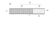
- FIG. 1 is a schematic view showing an embodiment of a catalyst layer filled in a reaction tube of a fixed bed reactor.
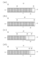
- FIG. 2 is a schematic diagram showing another embodiment of the catalyst layer filled in the reaction tube of the fixed bed reactor.
- XY indicating a range means "X or more and Y or less”.
- a gas containing achlorine is supplied to a fixed bed reactor filled with catalysts having different activities so that two or more catalyst layers are formed in the axial direction of the reaction tube.
- a production method for producing acrylic acid by vapor-phase catalytic oxidation of achlorein wherein the region of all catalyst layers up to 30% of the length of the total catalyst layers is directed from the rearmost portion on the gas outlet side toward the gas inlet side.
- the catalyst X having the highest activity among the catalysts filled in the entire catalyst layer is arranged in all or a part thereof, and the catalyst active component x in the catalyst X has Mo, V, and optionally Cu. However, when Cu is contained, it is 0.8 mol or less with respect to 12 mol of Mo, and the specific surface area of the catalytically active component x is 15 m 2 / g to 40 m 2 / g.
- acrylic acid is produced by vapor-phase catalytic oxidation of acrolein in the presence of molecular oxygen using a fixed-bed reactor including one or more reaction tubes.
- the term "in the presence of molecular oxygen” as used in the present invention means that at least molecular oxygen is present, and gas-phase contact oxidation in the presence of molecular oxygen is due only to molecular oxygen. It may be due to a molecular oxygen-containing gas.
- the reaction tube in the fixed bed reactor is filled with catalysts having different activities so that two or more catalyst layers are formed in the axial direction of the reaction tube.
- two or more catalyst layers according to the method for producing acrylic acid of the present invention filled in the reaction tube of this fixed bed reactor are collectively referred to as "total catalyst layer".
- a gas containing acrolein as a raw material hereinafter, also referred to as “acrolein-containing gas”
- acrolein-containing gas is supplied from the gas inlet side of all catalyst layers, and after a gas phase contact oxidation reaction.
- the reaction gas is discharged from the gas outlet side. That is, the acrolein-containing gas passes through the entire catalyst layer, so that vapor phase catalytic oxidation is performed.
- the most active catalyst X is arranged. That is, in the present invention, the catalyst X having the highest activity among the catalysts filled in the two or more catalyst layers (all catalyst layers) is in a specific region on the gas outlet side (rear side) of all the catalyst layers. It is characterized by being present in all or part of it.
- the "activity" in the present invention means the conversion rate of the starting material (that is, acrolein).
- the activity of the catalyst is determined by measuring the conversion rate of acrolein when the acrolein-containing gas is supplied to the catalyst layer (that is, a single layer) filled with one kind of catalyst under certain conditions. Can be evaluated. Therefore, by changing the type of catalyst to be filled and obtaining the acrolein conversion rate under the same conditions, it is possible to compare and evaluate the difference in activity of different catalysts.
- the method for evaluating the activity of the catalyst that is, the method for evaluating the activity of the catalyst by measuring the conversion rate of acrolein is not particularly limited, and the conditions of a generally known catalytic activity test method can be applied.
- the activity is evaluated under one specific condition in the examples described later, but the conditions for the activity evaluation can be appropriately set within the following ranges, for example.
- reaction tube length 200 mm to 500 mm ⁇
- Inner diameter of reaction tube 10 mm to 30 mm
- Catalyst layer length 50 mm to 150 mm -Gas composition: acrolein: 2 to 5% by volume, oxygen: 5 to 10% by volume, water vapor: 20 to 50% by volume
- Analysis method The concentration of achlorine and nitrogen in the gas discharged from the gas outlet side of the reaction tube 2 to 5 hours after the start of gas flow is analyzed by gas chromatography.
- the catalyst X contains a catalytically active component x.
- the catalytically active component x has Mo, V, and optionally Cu, and when Cu is contained, it is 0.8 mol or less with respect to 12 mol of Mo. That is, the catalytically active component x in the catalyst X does not contain Cu, or even if it contains Cu, it is 0.8 mol or less with respect to 12 mol of Mo (hereinafter, the form is "Cu-free or" Also referred to as "contains a small amount").
- the catalytically active component x has a specific surface area of 15 m 2 / g to 40 m 2 / g (hereinafter, also referred to as “specific specific surface area”), and the catalyst X containing the catalytically active component x is the whole. It has the highest activity among the catalysts present in the catalyst layer.
- the present inventors put the catalyst X having the highest activity among all catalyst layers, which contains no or a small amount of Cu and contains a catalytically active component x having a specific specific surface area, on the gas outlet side of all catalyst layers. It has been found that the yield of acrylic acid can be improved and the life of the catalyst can be extended by arranging the catalyst in all or a part of the specific region. The reason why the above effect is obtained by the configuration of the present invention is not always clear, but it is considered as follows.
- the present inventors use a catalyst containing Cu as a catalytically active component (hereinafter, may be referred to as a "catalyst containing Cu”), and the above-mentioned side reactions 1 and sub-reactions 1 and As a result of scrutinizing how the amount of reaction 2 changes by paying attention to the content of Cu in the catalyst, the side reaction 1 (combustion reaction of acrylic acid) decreases as the amount of Cu in the catalyst increases. It was found that the side reaction 2 (burning reaction of acrylic acid) increases. From this, the present inventors speculate that Cu may promote side reaction 2 (combustion reaction of acrylic acid) while suppressing side reaction 1 (combustion reaction of acrolein). Based on this, an diligent study was conducted.
- a catalyst containing Cu as a catalytically active component
- acrolein is almost changed to acrylic acid, so that the concentration in the gas is low, but the concentration of acrylic acid in the gas is high. That is, it is more important to suppress the side reaction 2 (combustion reaction of acrylic acid) than to suppress the side reaction 1 (combustion reaction of acrolein) in the latter half of the catalyst layer in order to improve the yield of acrylic acid. Therefore, in the method for producing acrylic acid of the present invention, a catalyst having a low Cu content (that is, a catalyst X containing no or a small amount of Cu as the catalytically active component x) is arranged in the latter half of the catalyst layer. It is presumed that the combustion of acrylic acid in the latter half of the layer was suppressed and the yield of acrylic acid was improved.
- the catalytically active component x contained in the catalyst X has a specific specific surface area.
- the specific surface area of the catalytically active component x is closely related to the catalytic activity and the likelihood of side reactions. Generally, the larger the specific surface area, the higher the catalytic activity, but when the specific surface area is excessively large, the side reaction Will increase. Therefore, since the catalytically active component x of the catalyst X arranged in the latter half of the catalyst layer has a specific specific surface area, it is possible to promote the acrylic acid formation reaction in the latter half of the catalyst layer and suppress the accompanying side reaction. , The structure is such that the effect of the present invention is further improved.
- a locally abnormally high temperature part may occur in the first half of the catalyst layer having a high acrolein concentration, which may accelerate the thermal deterioration of the catalyst.
- the temperature rise in the catalyst layer can be suppressed and the generation of an abnormally high temperature portion can be suppressed, but on the other hand, the conversion rate of acrolein is lowered, resulting in acrylic acid.
- the yield decreases.
- a catalyst X having a specific specific surface area, which is highly active and contains no Cu or contains a small amount, is arranged in the latter half of the catalyst layer while lowering the reaction temperature.
- a highly active catalyst in the latter half of the catalyst layer where the temperature rise is unlikely to occur while suppressing the temperature rise in the first half of the catalyst layer.
- the abnormal temperature rise in the first half of the catalyst layer was suppressed and the catalyst life was improved.
- such a mechanism is merely speculation and does not limit the technical scope of the present invention.
- FIG. 1 and 2 are schematic views showing an embodiment of a catalyst layer filled in the reaction tube 10 of a fixed bed reactor. As shown in FIG. 1, when the acrylic acid of the present invention is produced, the reaction tube 10 of the fixed bed reactor is filled with a plurality of types of catalysts to form the entire catalyst layer 21.
- Acrolein-containing gas is supplied to the reaction tube 10 of the fixed-bed reactor from the frontmost end portion 11 of the catalyst layer, the supplied acrolein-containing gas passes through all the catalyst layers 21, and the gas after the reaction is the rearmost end portion of the catalyst layer. It is discharged from 12.
- the frontmost end 11 side of the catalyst layer is also referred to as a gas inlet side
- the frontmost catalyst layer 11 is also referred to as the frontmost gas inlet side of all catalyst layers
- the rearmost 12 side of the catalyst layer is the gas outlet side and the catalyst.
- the rearmost end portion 12 of the layer is also referred to as the rearmost portion on the gas outlet side of all catalyst layers.
- the entire catalyst layer 21 in the reaction tube 10 of the fixed bed reactor is composed of a catalyst layer 22 containing a catalyst of a type different from that of the catalyst X and a catalyst layer 23 containing the catalyst X.
- the catalyst layer 23 containing the catalyst X is a region 31 (hereinafter, simply “region”) up to 30% of the length of the total catalyst layer 21 from the rearmost end portion 12 of the catalyst layer toward the gas inlet side. 31 ”).
- the catalyst layer 23 containing the catalyst X is arranged in all the regions 31 up to 30% of the length of the total catalyst layer from the rearmost end portion 12 of the catalyst layer toward the gas inlet side. Is. That is, the form of FIG. 1 is composed of a catalyst layer 23 containing the catalyst X from the end L of the region 31 to the rearmost end 12 of the catalyst layer.
- the catalyst layer 23 containing the catalyst X may be arranged in a part of the region 31 up to 30% of the length of the total catalyst layer 21 from the rearmost end portion 12 of the catalyst layer toward the gas inlet side. good.
- the form in which the catalyst layer 23 including the catalyst X is arranged will be described with reference to FIG.
- the catalyst layer 23 containing the catalyst X is arranged in a region 31 of the region 31 from the rearmost end portion 12 of the catalyst layer toward the gas inlet side up to 10% of the length of the total catalyst layer 21. Has been done.
- FIG. 2A the catalyst layer 23 containing the catalyst X is arranged in a region 31 of the region 31 from the rearmost end portion 12 of the catalyst layer toward the gas inlet side up to 10% of the length of the total catalyst layer 21.
- the catalyst layer 23 containing the catalyst X is arranged in a region 31 of the region 31 from the rearmost end portion 12 of the catalyst layer toward the gas inlet side up to 3% of the length of the total catalyst layer 21.
- the catalyst layer 23 containing the catalyst X is arranged in a region 31 of the region 31 from the gas inlet side to the gas outlet side up to 10% of the length of the total catalyst layer 21. ..
- the catalyst layer 23 containing the catalyst X is arranged in a region located in the middle portion of the region 31, which is 3% of the length of the total catalyst layer 21.
- a catalyst of a type different from that of the catalyst X is provided adjacent to the catalyst layer 23 containing the catalyst X on the outlet side of the catalyst layer 23 containing the catalyst X.
- a catalyst layer 24 containing the catalyst layer 24 is arranged.
- FIGS. 2A to 2D show a form in which the catalyst layer 23 containing the catalyst X is arranged at the rearmost part of the region 31 (that is, the rearmost part of the total catalyst layer 21), and is shown in FIG. 2 (c).
- FIG. 2D shows a form in which the catalyst layer 23 containing the catalyst X is arranged in the middle part of the region 31. be.
- the catalyst layer 23 containing the catalyst X may be arranged in any of the regions 31.
- the length of the entire catalyst layer 21 means the distance from the frontmost end portion 11 of the catalyst layer to the rearmost end portion 12 of the catalyst layer in the direction parallel to the tube axis, and at this time, at both ends of the total catalyst layer 21. It is obtained by calculating the distance between the located catalysts.
- the "length of the catalyst layer” may also be referred to as “layer length” or "layer height”.
- a method of measuring the layer length of the catalyst layer filled in the reaction tube for example, a method of measuring with a measure or the like can be mentioned.
- a stopper such as a perforated plate so as to be perpendicular to the tube axis direction. Is placed at a predetermined position in the reaction tube (for example, a position corresponding to the frontmost end 11 of the catalyst layer in FIG. 1); (2) at the upper opening of the reaction tube (for example, the rearmost end 12 of the catalyst layer in FIG. 1).
- the "upper surface of the perforated plate" is only the top of the already filled catalyst layer, and the operations of (2) to (4) are filled with each catalyst. You can do it in time. Thereby, the layer length of each catalyst layer and the layer length of all catalyst layers can be calculated.
- the distance D1 and the distance D2 are measured in parallel with the tube axis direction of the reaction tube. At that time, the average value may be the distance D1 and the distance D2 by measuring several points (for example, three points). The number of measurement points may be more than a statistically reliable number.
- the layer length of the catalyst layer 23 including the catalyst X is 3 to 30% of the length of the total catalyst layer 21.
- the catalyst layer 23 containing the catalyst X is arranged at the rearmost part of all the catalyst layers 21 (the forms of FIGS. 1, 2 (a) and 2 (b)). Therefore, it is preferable that the catalyst layer 23 containing the catalyst X is arranged at the rearmost part of the total catalyst layer 21, and the layer length of the catalyst layer 23 containing the catalyst X is 3 to 30% of the length of the total catalyst layer 21. be.
- the catalyst layer 23 containing the catalyst X is arranged at the rearmost part of the total catalyst layer 21, and the layer length of the catalyst layer 23 including the catalyst X is 5 to 25%, 5 to 20% of the length of the total catalyst layer 21. More preferably, it is 5 to 15%, or 6 to 10%. With the above configuration, the effect of the present invention can be further exerted.
- the catalyst layer 23 containing the catalyst X may be present in a region other than the region 31 as long as it is arranged in any of the regions 31. Therefore, for example, as the arrangement form of the catalyst of the present invention, the catalyst layer 23 containing the catalyst X is arranged in either one of the regions 31 or the region on the inlet side from the end L of the region 31; the catalyst. A form in which the catalyst layer 23 containing X is arranged in a region up to 40% of the length of the total catalyst layer 21 from the rearmost end portion 12 of the catalyst layer toward the gas inlet side is also included.
- the catalyst X does not contain Cu or contains a small amount of Cu, the combustion reaction of acrolein may increase. Therefore, when the catalyst layer 23 containing the catalyst X is arranged beyond the region 31 toward the gas inlet side, the total length of the catalyst layer is 35 from the catalyst layer rearmost end 12 toward the gas inlet side. It is preferably arranged in a region up to%, and more preferably arranged in a region up to 33% of the total catalyst layer length. In this case, the effect of the present invention can be fully exerted.
- the catalyst X contains a catalytically active component x.
- the catalytically active component x has Mo, V, and optionally Cu, and when Cu is contained, it is 0.8 mol or less with respect to 12 mol of Mo, and the specific surface area of the catalytically active component x is 15 m 2 / g or more. It is 40 m 2 / g. If the catalytically active component x has the constitution and the catalyst X containing the catalytically active component x is present in all or a part of a specific region, acrylic acid can be produced in a high yield for a long period of time.
- the composition of the catalytically active component x (however, excluding oxygen representing an oxidized state) is determined by the following general formula (1): Mo 12 Cu a V b A c B d C e D f Eg (1)
- Mo molybdenum
- Cu copper
- V vanadium
- A is at least one element selected from niobium, tungsten and tantalum
- B is at least one element selected from antimony and tellurium.
- Species element, C is at least one element selected from chromium, manganese, iron, cobalt, nickel, zinc, bismuth, tin, tallium and rare earth elements
- D is selected from alkali metals and alkaline earth metals.
- E is at least one element selected from silicon, aluminum, titanium, zirconium, and cerium
- a, b, c, d, e, f and g are Cu, V
- c, d, e, f and g are the total number of atoms of each element represented by A, B, C and D, respectively.
- a is 0 ⁇ a ⁇ 0.8, preferably 0 ⁇ a ⁇ 0.8, and more preferably 0 ⁇ a ⁇ 0.6. That is, the amount of Cu in the catalytically active component x is preferably less than 0.8 mol, more preferably 0.6 mol or less, and 0.5 mol or less, 0.4 mol, relative to 12 mol of Mo. Hereinafter, it may be 0.3 mol or less, 0.2 mol or less, or 0.1 mol or less. If the amount of Cu exceeds 0.8 mol with respect to 12 mol of Mo, as described above, the produced acrylic acid is further burned, which is not preferable.
- c is preferably 0 ⁇ c ⁇ 3.0, more preferably 0 ⁇ c ⁇ 2.5, still more preferably 0 ⁇ c ⁇ 2.0, and further. More preferably, 0 ⁇ c ⁇ 1.5. That is, the amount of A in the catalytically active component x is preferably 0 mol or more and 3.0 mol or less, more preferably 0 mol or more and 2.5 mol or less, still more preferably 0, with respect to 12 mol of Mo. It is mol or more and 2.0 mol or less, and even more preferably 0 mol or more and 1.5 mol or less.
- the catalytically active component x may or may not contain tungsten (W).
- W tungsten
- A is at least one element selected from niobium, tungsten and tantalum
- c ( Ac ) in A is 0 ⁇ c ⁇ 12 and c in W (here, for convenience).
- C'" (W c' ) is 0 ⁇ c' ⁇ 3.0.
- c' is more preferably 0 ⁇ c' ⁇ 2.5, even more preferably 0 ⁇ c' ⁇ 2.0, and even more preferably 0 ⁇ c' ⁇ 1.5.
- the amount of W in the catalytically active component x is preferably 0 mol or more and 3.0 mol or less, more preferably 0 mol or more and 2.5 mol or less, still more preferably 0, with respect to 12 mol of Mo. It is mol or more and 2.0 mol or less, and even more preferably 0 mol or more and 1.5 mol or less.
- the catalytically active component x may be in a form containing Cu, a form containing W, or a form containing Cu and W.
- the lower limit of a in the formula (1) is preferably 0 ⁇ a, more preferably 0.1 ⁇ a, and even more preferably 0.1 ⁇ a. 0.2 ⁇ a. That is, the amount of Cu in the catalytically active component x is preferably more than 0 mol, more preferably 0.1 mol or more, and further preferably 0.2 mol or more with respect to 12 mol of Mo. In this case, the amount of Cu in the catalytically active component x is preferably less than 0.8 mol, more preferably 0.6 mol or less, and 0.5 mol or less, 0.4 mol with respect to 12 mol of Mo.
- A contains tungsten (W), in which case c ( Ac ) in A is 0 ⁇ c ⁇ 12 and c'(in W).
- W c' ) is 0 ⁇ c' ⁇ 3.0. That is, when the catalytically active component x contains W, the amount of W in the catalytically active component x is more than 0 and 3.0 mol or less with respect to 12 mol of Mo.
- the specific surface area tends to increase and the catalytic activity tends to be improved.
- the acrylic acid selectivity decreases and the acrylic acid yield decreases. There is.
- c'(W c' ) in W is preferably 0.1 ⁇ c' ⁇ 2.5, more preferably 0. .3 ⁇ c' ⁇ 2.0, more preferably 0.5 ⁇ c' ⁇ 1.5. That is, the amount of W in the catalytically active component x is preferably 0.1 mol or more and 2.5 mol or less, more preferably 0.3 mol or more and 2.0 mol or less, and further, with respect to 12 mol of Mo. It is preferably 0.5 mol or more and 1.5 mol or less.
- the catalytically active component x preferably has f and g of 0 in the above formula (1). Further, in the composition of the above formula (1), the C component may lower the acrylic acid yield in some cases, so e is preferably 0. That is, the composition of the catalytically active component x (excluding oxygen representing the oxidation state) when e, f and g are 0 is represented by the following formula (2).
- the lower limit of a in the formula (2) is preferably 0 ⁇ a, more preferably 0.1 ⁇ a, and even more preferably 0.1 ⁇ a. 0.2 ⁇ a. That is, the amount of Cu in the catalytically active component x is preferably more than 0 mol, more preferably 0.1 mol or more, and further preferably 0.2 mol or more with respect to 12 mol of Mo. In this case, the amount of Cu in the catalytically active component x is preferably less than 0.8 mol, more preferably 0.6 mol or less, and 0.5 mol or less, 0.4 mol with respect to 12 mol of Mo. It may be less than a mole and less than 0.3 mol.
- A contains tungsten (W), in which case c ( Ac ) in A is 0 ⁇ c ⁇ 12 and c'(in W).
- W c' ) is 0 ⁇ c' ⁇ 3.0. That is, when the catalytically active component x contains W, the amount of W in the catalytically active component x is more than 0 and 3.0 mol or less with respect to 12 mol of Mo.
- the specific surface area tends to increase and the catalytic activity tends to be improved.
- the acrylic acid selectivity decreases and the acrylic acid yield decreases. There is.
- c'(W c' ) in W is preferably 0.1 ⁇ c' ⁇ 2.5, more preferably 0. .3 ⁇ c' ⁇ 2.0, more preferably 0.5 ⁇ c' ⁇ 1.5. That is, the amount of W in the catalytically active component x is preferably 0.1 mol or more and 2.5 mol or less, more preferably 0.3 mol or more and 2.0 mol or less, and further, with respect to 12 mol of Mo. It is preferably 0.5 mol or more and 1.5 mol or less.
- the catalytically active component x may be in a form containing no Cu, that is, in a form in which a is 0, from the viewpoint of suppressing the combustion reaction of acrylic acid and, as a result, improving the yield of acrylic acid.
- the composition of the formula (2) in the form containing no Cu for example, the composition represented by the following formula (2-1) is preferable.
- Mo 12 V b Ac B d (2-1)
- the definitions of Mo and V are the same as in formula (1), where A is at least one element selected from niobium and tungsten, and B is at least one selected from antimony and tellurium. It is an element of the species, and the definitions of b, c, and d are the same as those in the formulas (1) and (2).
- the catalytically active component x may be in a form containing Cu, and when it contains Cu, it is represented by, for example, the following formula (2-2) as a compound of the formula (2). Those are preferable.
- Mo 12 Cu a V b A c B d (2-2)
- the definitions of Mo, Cu, and V are the same as in formula (1), where A is at least one element selected from niobium and tungsten, and B is selected from antimony and tellurium. It is at least one element, 0 ⁇ a ⁇ 0.8, and the definitions of b, c, and d are the same as those in the formulas (1) and (2).
- the lower limit value of a is preferably 0.1 ⁇ a, more preferably 0.2 ⁇ a. That is, the amount of Cu in the catalytically active component x is preferably 0.1 mol or more, more preferably 0.2 mol or more, with respect to 12 mol of Mo. In this case, the amount of Cu in the catalytically active component x is preferably less than 0.8 mol, more preferably 0.6 mol or less, and 0.5 mol or less, 0.4 mol with respect to 12 mol of Mo. It may be less than a mole and less than 0.3 mol.
- A contains tungsten (W), in which case c ( Ac ) in A is 0 ⁇ c ⁇ 12 and c in W. '(W c' ) is 0 ⁇ c' ⁇ 3.0. That is, when the catalytically active component x contains W, the amount of W in the catalytically active component x is more than 0 and 3.0 mol or less with respect to 12 mol of Mo.
- W tungsten
- the specific surface area tends to increase and the catalytic activity tends to be improved.
- the acrylic acid selectivity decreases and the acrylic acid yield decreases. There is.
- c'(W c' ) in W is preferably 0.1 ⁇ c' ⁇ 2.5, which is more preferable. Is 0.3 ⁇ c ′ ⁇ 2.0, and more preferably 0.5 ⁇ c ′ ⁇ 1.5. That is, the amount of W in the catalytically active component x is preferably 0.1 mol or more and 2.5 mol or less, more preferably 0.3 mol or more and 2.0 mol or less, and further, with respect to 12 mol of Mo. It is preferably 0.5 mol or more and 1.5 mol or less.
- the specific surface area of the catalytically active component x is 15 m 2 / g to 40 m 2 / g. If the specific surface area of the catalytically active component x is less than 15 m 2 / g, the catalytic activity is insufficient and the yield of acrylic acid decreases. When the specific surface area of the catalytically active component x exceeds 40 m 2 / g, the activity of the catalyst is too high and the produced acrylic acid is burned, resulting in a decrease in the yield of acrylic acid.
- the specific surface area of the catalytically active component x is preferably 15 m 2 / g to 35 m 2 / g, more preferably 15 m 2 / g to 30 m 2 / g, and even more preferably 15 m 2 / g to 25 m 2 / g. It is even more preferably 16 m 2 / g to 25 m 2 / g, even more preferably 17 m 2 / g to 25 m 2 / g, and even more preferably 18 m 2 / g to 25 m 2 / g. ..
- the specific surface area of the catalytically active component x is within the above range, it is possible to suppress the combustion of acrylic acid while having sufficient catalytic activity, and acrylic acid can be produced in high yield for a long period of time.
- the specific surface area of the catalytically active component x shall be calculated by the method described in Examples.
- the average particle size of the catalytically active component x is not particularly limited, but is preferably 0.1 ⁇ m to 500 ⁇ m, and more preferably 1 ⁇ m to 100 ⁇ m from the viewpoint of excellent supportability.
- the average particle size of the catalytically active component x can be calculated as, for example, the median diameter (volume-based distribution) when the particle size distribution is measured using a particle size distribution meter such as a laser diffraction / scattering type particle size distribution measuring device.
- the catalyst X may be obtained by molding the catalyst active component x alone, and may contain alumina, silica, silica-alumina, titania, zirconia, magnesia, steatite, cordierite, silica-magnesia, silica-magnesia-alumina, and the like. It may be supported on a carrier such as silicon carbide, silicon nitride, zeolite, or stainless steel to form a carrier. In the case of a catalyst obtained by molding the catalytically active component x alone, the catalyst X is composed of the catalytically active component x. When the catalytically active component x is supported on a carrier, the carrier composed of the catalytically active component x and the carrier (supporting the catalytically active component x on the carrier) becomes the catalyst X.
- alumina silica, silica-alumina, titania, zirconia, magnesia, steatite, cordierite, silic
- the shapes of the catalyst X and the carrier are not particularly limited as long as the shapes according to the purpose such as pellets, granules, spheres, rings, and honeycombs can be appropriately selected.
- the size of the catalyst X used in the present invention is not particularly limited, but the particle size of the catalyst X is preferably 1 mm to 12 mm, more preferably 3 mm to 10 mm.
- the catalyst X obtained by molding the catalyst active component x having the above average particle size may have the particle size of the catalyst X.
- a carrier having a particle size smaller than the target particle size (that is, the particle size of the catalyst X) by 0.5 to 1.0 mm is used.
- a catalyst X having a target particle size (specifically, a catalyst X carrying a catalyst active component x) can be obtained.
- the particle size of the catalyst X refers to the diameter of the spherical catalyst in the case of a spherical catalyst, and the diameter of the circumscribed sphere of the catalyst in the case of other shapes.
- the average particle size of the catalyst X is within the above range, the reaction tube of the catalyst X can be easily filled and the pressure loss of the catalyst layer can be reduced, so that energy saving such as reduction of the electric power cost of the blower can be achieved. Can be achieved.
- the average particle size of the catalyst X can be measured by measuring the particle size of 100 catalysts X arbitrarily sampled with a caliper and calculating the average value.
- the carrying ratio of the catalytically active component x in the catalyst X that is, the mass of the catalytically active component x with respect to the mass of the catalyst X (the total mass of the catalytically active component x and the carrier).
- the proportion is preferably 5 to 50% by mass, more preferably 10 to 40% by mass, and even more preferably 15 to 30% by mass.
- the shape of the catalyst X to be filled in the catalyst layer may be the same or different, but it is preferable to fill the catalyst X having the same shape.
- the method for producing the catalyst X can be prepared by a method generally used for preparing this type of catalyst.
- each starting material containing each metal element constituting the catalyst active component x is mixed with water or the like and dissolved or dispersed to prepare a solution or a dispersion liquid.
- a production method including; a step of obtaining the catalytically active component x by firing a precursor of the catalytically active component x; and a step of molding the catalytically active component x; Further, it is obtained by a production method including a step of forming a precursor of the powdery catalytically active component x after obtaining a precursor of the powdery catalytically active component x; and a step of firing the molded precursor; You can also do it.
- each starting material containing each metal element constituting the catalytically active component x is mixed with water or the like and dissolved or dispersed to prepare a solution or a dispersion.
- a production method including the step of obtaining a carrier (catalyst X) and; Further, a step of obtaining a powdery catalytically active component x by firing a precursor of the powdery catalytically active component x; and by contacting the powdery catalytically active component x with a carrier, the catalytically active component x was supported. It can also be obtained by a production method including a step of obtaining a carrier (catalyst X); and, if necessary, a step of re-baking the carrier;
- the starting material used for preparing the catalytically active component x is not particularly limited, and commonly used ammonium salts, organic ammonium salts, nitrates, carbonates, oxalates, organic carboxylates, sulfates, and water of each metal element are used. Oxides, oxides, metal species and the like are used, but compounds containing a plurality of metal elements may be used.
- the catalytically active ingredient of the present invention can obtain a catalytically active ingredient having a desired specific surface area by adjusting the firing temperature, firing time, firing atmosphere, slurry preparation, reaction method, and the like.
- the firing temperature of the catalyst containing niobium or tantalum is 250 ° C. to 750 ° C., preferably 280 ° C. to 700 ° C., more preferably 300 ° C. to 660 ° C., and the firing time is preferably 1 hour to 20 hours, 1 hour to 12 hours. Is more preferable, and 1 hour to 8 hours is even more preferable.
- the firing temperature of the catalyst containing no niobium and tantalum is 250 ° C. to 600 ° C., preferably 300 ° C.
- the firing atmosphere can be appropriately selected from an air atmosphere, an inert gas atmosphere, a steam atmosphere, an atmosphere containing a reducing gas such as ammonia and hydrogen, or an atmosphere of a mixed gas thereof. Since the relationship between the firing atmosphere and the specific surface area changes depending on the composition of the catalytically active ingredient, the firing atmosphere may be appropriately selected according to the composition of the catalytically active ingredient.
- the slurry may be prepared and reacted under atmospheric pressure, but in general, the specific surface area of the catalytically active component is higher when the catalyst for acrolein oxidation is carried out under high temperature and high pressure conditions using an autoclave. Therefore, it is preferable.
- the temperature at which the slurry is prepared and reacted under atmospheric pressure is 60 ° C. to 120 ° C., preferably 70 ° C. to 100 ° C. At this time, the higher the temperature, the higher the solubility of the raw material in the slurry, but if the temperature is too high, the concentration of the slurry increases due to the evaporation of water and the solubility of the raw material decreases.
- Reflux may be performed to suppress an increase in slurry concentration during slurry preparation.
- the temperature at which the slurry is prepared and reacted in the autoclave is 120 ° C. to 300 ° C., preferably 150 ° C. to 250 ° C., and the pressure is 0.5 MPa to 10 MPa, preferably 1 MPa to 5 MPa.
- the temperature and pressure are high, the reaction occurs quickly and the preparation time can be shortened, but on the other hand, expensive high-pressure equipment is required.
- the method for detecting the catalyst X (catalyst active component x) of the present invention is not particularly limited, and examples thereof include the following methods.
- 20 g of the catalyst X is placed in a stainless steel cylindrical container having an inner diameter of 70 mm and a height of 140 mm, and the entire container is shaken in order to shake off the catalytically active component x on the surface of the catalyst X.
- powders of 100 ⁇ m or less are sieved and XRF analysis is performed to identify the elements and calculate their contents. Further, the specific surface area of the powder having a thickness of 100 ⁇ m or less is measured using a BET specific surface area measuring device. If the elements contained in the powder, their contents, and the specific surface area of the powder are the same as the catalytically active component x of the present invention, the catalytically active component is regarded as the catalytically active component x.
- the number of catalyst layers other than the catalyst layer containing the catalyst X is preferably large from the viewpoint of suppressing the temperature rise of the catalyst layer, but the catalyst X is preferable. If the catalyst layer containing the above and the other catalyst layer are present, the desired effect of the present invention can be sufficiently obtained. Therefore, the total number of catalyst layers (total number of catalyst layers including catalyst X and other catalyst layers) may be 2 or more, preferably 3 to 5 layers.
- the target reaction conditions and the catalyst Since it depends on the composition, shape, and size of the catalyst layer containing X and other catalyst layers, it cannot be unconditionally specified, and it may be appropriately selected so as to obtain the optimum activity and selectivity as a whole. ..
- the catalyst to be filled in each catalyst layer other than the catalyst layer containing the catalyst X (hereinafter referred to as a catalyst other than the catalyst X) is not particularly limited as long as it converts achlorine into acrylic acid, but is generally used for the vapor phase catalytic oxidation reaction. Known catalysts used can be used.
- the catalyst other than the catalyst X may be a molding catalyst in which the catalyst active component has a certain shape, a supported catalyst in which the catalyst active component is supported on an arbitrary inert carrier having a certain shape, or these molding catalysts. And a supported catalyst may be used in combination. Further, in the other catalyst layers, the shape of the catalyst to be filled in each catalyst layer may be the same or different, but usually, the same catalyst layer is filled with a catalyst having the same shape and / or a supported catalyst. preferable.
- the shape of the catalyst other than the catalyst X is not particularly limited as long as a shape suitable for the purpose such as pellet shape, granular shape, spherical shape, ring shape, and honeycomb shape may be appropriately selected.
- the supported ratios of the catalysts filled in each catalyst layer may be the same or different.
- the carrier is not particularly limited, and a carrier that can be usually used for producing a catalyst for vapor phase catalytic oxidation can be used.
- Specific examples of the carriers that can be used include alumina, silica, silica-alumina, titania, zirconia, magnesia, steatite, cordierite, silica-magnesia, silica-magnesia-alumina, silicon carbide, silicon nitride, zeolite, and stainless steel.
- the carrying ratio of the catalyst is not particularly limited, but is preferably 10 to 100% by mass.
- the catalyst X is filled in the reactor tube of the fixed bed reactor before initiating the vapor-phase catalytic oxidation reaction of achlorein using the fixed bed reactor, that is, before supplying the achlorine-containing gas to the fixed bed reactor. It is also possible, after the gas-phase catalytic oxidation reaction is continued for a certain period of time, the reaction is temporarily stopped, the catalyst at the outlet of the reaction tube of the fixed bed reactor is partially replaced with the catalyst X, and then the achlorine-containing gas is supplied to carry out the reaction. You can also resume. Further, the reaction can be temporarily stopped, and the reaction can be restarted after the catalyst X is additionally filled in the last stage of the catalyst layer of the reaction tube of the fixed bed reactor.
- a method of filling the reaction tube of a fixed bed reactor with a catalyst is also provided. Specifically, it is a method of filling the reaction tube of a fixed bed reactor used for producing acrylic acid by vapor-phase catalytic oxidation of achlorine with a catalyst, and two or more kinds of catalysts having different activities are used in the reaction tube.
- the catalyst X which is filled so that two or more catalyst layers are formed in the axial direction of the tube and has the highest activity among the catalysts filled in all the catalyst layers, is the last on the gas outlet side of all the catalyst layers.
- the catalyst layer is filled so as to be arranged in all or a part of the region up to 30% of the length of the entire catalyst layer, and the catalyst active component x in the catalyst X is optionally Mo and V.
- the catalyst active component x in the catalyst X is optionally Mo and V.
- the amount is 0.8 mol or less with respect to 12 mol of Mo
- the specific surface area of the catalytically active component x is 15 m 2 / g to 40 m 2 / g.
- a method of filling the catalyst used is provided.
- the catalyst X can be prepared by the method described in the present specification, and the specific surface area and activity of the catalyst can be measured by the method described in the present specification and the method described in Examples described later.
- a gas containing acrolein is used as a raw material.
- the acrolein-containing gas includes a gas containing acrolein alone, a mixed gas containing at least one of molecular oxygen and an inert gas, a mixed gas containing acrolein obtained by vapor-phase catalytic oxidation of propylene, and a dehydration reaction of glycerin. Examples thereof include a mixed gas containing acrolein to be obtained. Further, if necessary, air or oxygen, an inert gas such as water vapor or nitrogen, or other gas can be added to these acrolein-containing gases for use.
- the reaction conditions in the production of acrylic acid of the present invention are not particularly limited, and any of the conditions used for this type of reaction can be carried out.
- an achlorine-containing gas a mixed gas composed of 7 to 13% by volume of achloraine, 2 to 20% by volume of molecular oxygen, 2 to 40% by volume of water vapor, and an inert gas such as nitrogen is used as the balance.
- the reaction is carried out by supplying from the gas inlet side of the reaction tube of the fixed bed reactor at a space velocity of 1000 to 10000 h -1 (STP) under a pressure of 0.1 to 1.0 MPa in a reaction temperature range of 200 to 400 ° C.
- STP space velocity of 1000 to 10000 h -1
- the reaction may be carried out by contacting with all the catalyst layers in the tube.
- the reaction temperature is preferably 220 to 300 ° C, more preferably 250 to 285 ° C.
- the life of the catalyst can be extended and the acrylic content is high. It is possible to express the acid yield.
- the reaction temperature is preferably 220 to 300 ° C. even after 8000 hours have passed from the start of the reaction (start of distribution of acrolein-containing gas). , More preferably 250-285 ° C. That is, according to the present invention, the occurrence of an abnormal temperature rise in the catalyst layer is suppressed, and the life of the catalyst is extended.
- the reaction temperature means the temperature of the heat medium, and specifically, as in the examples described later, the temperature of the heat medium in the vicinity of the middle portion of the layer lengths of all the catalyst layers during the reaction. Can be grasped by measuring.
- the life of the catalyst can be extended even under high load conditions, and a high acrylic acid yield can be exhibited. If: (acrylic acid amount per unit volume of the catalyst is produced in a unit time STY [Standard Time Yield]) is the 400kg / (m 3 ⁇ h -1 ) (STP) or more specifically, for example, space-time yield Also, it is possible to extend the life of the catalyst and increase the yield of acrylic acid.
- the vapor-phase catalytic oxidation reaction in the present invention may be carried out by a normal single distribution method or a recycling method, and can be carried out under conditions generally used for this type of reaction.
- Catalyst preparation method 1.
- 1000 g of ammonium paratungate tetrahydrate, 303 g of ammonium metavanadate, and 153 g of ammonium paratungstate tetrahydrate were dissolved while heating and stirring 10000 g of pure water.
- 171 g of copper nitrate trihydrate was dissolved while heating and mixing 400 g of pure water.
- the two obtained aqueous solutions were mixed, and 35 g of antimony trioxide and 424 g of aluminum oxide were further added to obtain a starting material mixture.
- the obtained mixture of starting materials was dried with a spray dryer, and then the obtained dried product was pulverized and sieved to 100 ⁇ m or less to obtain a precursor of a catalytically active ingredient.
- 3960 g of spherical silica-alumina carrier having an average diameter of 8 mm was charged into a dish-type rolling granulator, and then, in a state where the rotary dish was rotated, the precursor of the above catalytically active component was gradually sprayed while spraying pure water as a binder. After being carried on a carrier, it was dried with hot air at about 90 ° C. to obtain a carrier carrying a precursor of a catalytically active ingredient.
- the obtained carrier was calcined at 400 ° C.
- Catalyst (1) Mo 12 Cu 1.5 V 5.5 W 1.2 Sb 0.5 Al 17.6
- catalysts (2) and (3) In the preparation method of catalyst (1), precursors of catalytically active components in catalysts (2) and catalysts (3) were obtained in the same manner except that aluminum oxide was not used. rice field. Next, in the method for preparing the catalyst (1), a spherical silica-alumina carrier having an average diameter of 5 mm was used as the carrier, except that the amount of the precursor of the catalyst active component to be charged into the dish-type rolling granulator was adjusted. Similarly, a carrier in the catalyst (2) having a carrying ratio of 30% by mass and a carrier in the catalyst (3) having a carrying ratio of 40% by mass are obtained, and these are further calcined under the same conditions to form a catalyst.
- the specific surface area of the catalytically active ingredient was 9.9 m 2 / g.
- the metal element composition of the catalytically active component excluding oxygen was as follows. Catalyst (2), catalyst (3): Mo 12 Cu 1.5 V 5.5 W 1.2 Sb 0.5
- the dried product was pulverized and sieved to 100 ⁇ m or less to obtain a precursor of a catalytically active ingredient.
- 2700 g of a spherical silica-alumina carrier having an average diameter of 5 mm was charged into a dish-type rolling granulator, and then, in a state where the rotary dish was rotated, the precursor of the above catalytically active component was gradually sprayed while spraying pure water as a binder. After being carried on a carrier, it was dried with hot air at about 90 ° C. to obtain a carrier.
- the obtained carrier was calcined at 600 ° C. for 6 hours in a nitrogen atmosphere to obtain a catalyst (4).
- the loading ratio was 23% by mass, and the specific surface area of the catalytically active component was 23.7 m 2 / g.
- the metal element composition of the catalytically active component excluding oxygen was as follows. Catalyst (4): Mo 12 V 3.6 Nb 1.5 Sb 1.2
- catalyst (5) was obtained in the same manner except that it was calcined at 640 ° C.
- the specific surface area of the catalytically active ingredient was 11.3 m 2 / g.
- the metal element composition of the catalytically active component of the catalyst (5) is the same as that of the catalyst (4).
- catalyst (6) While heating and stirring 3500 g of pure water, 576 g of molybdenum oxide (VI), 109 g of vanadium oxide (V), 58 g of antimony trioxide, 8.0 g of copper (II) oxide, niobium ammonium pentoxide (Nb 2 O) 260 g (containing 24.8% by mass as 5 ) was added, and the mixture was heated and stirred at 175 ° C. for 24 hours in a closed autoclave to obtain a starting material mixture. The obtained mixture of starting materials was filtered to separate the precipitate, and dried in a box-type dryer at 80 ° C. for 15 hours.
- the dried product was pulverized and sieved to 100 ⁇ m or less to obtain a precursor of a catalytically active ingredient.
- 2700 g of a spherical silica-alumina carrier having an average diameter of 5 mm was charged into a dish-type rolling granulator, and then, in a state where the rotary dish was rotated, the precursor of the above catalytically active component was gradually sprayed while spraying pure water as a binder. After being carried on a carrier, it was dried with hot air at about 90 ° C. to obtain a carrier.
- the obtained carrier was calcined at 590 ° C. for 6 hours in a nitrogen atmosphere to obtain a catalyst (6).
- the loading ratio was 23% by mass, and the specific surface area of the catalytically active component was 27.7 m 2 / g.
- the metal element composition of the catalytically active component excluding oxygen was as follows. Catalyst (6): Mo 12 Cu 0.3 V 3.6 Nb 1.5 Sb 1.2
- the mixed solution A and the mixed solution B were mixed to obtain a starting material mixed solution. After drying the starting material mixture with a spray dryer, the obtained dried product was pulverized and sieved to 100 ⁇ m or less to obtain a precursor of a catalytically active ingredient. 9000 g of a spherical silica-alumina carrier having an average diameter of 5 mm was charged into a dish-type rolling granulator, and then, in a state where the rotary dish was rotated, the precursor of the above catalytically active component was gradually sprayed while spraying pure water as a binder. After being carried on a carrier, it was dried with hot air at about 90 ° C. to obtain a carrier. The obtained carrier was calcined at 600 ° C.
- Catalyst (7) Mo 12 V 2.9 Nb 1.3 Sb 3.1
- the dried product was pulverized and sieved to 100 ⁇ m or less to obtain a precursor of a catalytically active ingredient.
- 2850 g of a spherical silica-alumina carrier having an average diameter of 5 mm was charged into a dish-type rolling granulator, and then, in a state where the rotary dish was rotated, the precursor of the above catalytically active component was gradually sprayed while spraying pure water as a binder. After being carried on a carrier, it was dried with hot air at about 90 ° C. to obtain a carrier.
- the obtained carrier was calcined at 600 ° C. for 6 hours in a nitrogen atmosphere to obtain a catalyst (8).
- the loading ratio was 23% by mass, and the specific surface area of the catalytically active component was 19.5 m 2 / g.
- the metal element composition of the catalytically active component excluding oxygen was as follows. Catalyst (8): Mo 12 V 3.6 Nb 1.5 Te 2.0
- catalyst (9) 412 g of ammonium paramolybdate tetrahydrate and 73 g of ammonium metavanadate were dissolved while heating and stirring 10000 g of pure water at 80 ° C. After cooling this solution to 50 ° C., 307 g of an aqueous dispersion containing 42 g of metal tellurium particles obtained by reducing tellurium dioxide with hydrazine was added, and 128 g of 10% aqueous ammonia was added dropwise to obtain a mixed solution C.
- the obtained calcined product was pulverized and sieved to 100 ⁇ m or less to obtain a catalytically active component.
- 1650 g of a spherical silica-alumina carrier having an average diameter of 5 mm was charged into a dish-type rolling granulator, and then the catalytically active component was gradually charged while spraying pure water as a binder in a state where the rotary dish was rotated.
- the catalyst (9) was obtained by drying with hot air at about 90 ° C.
- the loading ratio was 23% by mass, and the specific surface area of the catalytically active component was 15.1 m 2 / g.
- the metal element composition of the catalytically active component excluding oxygen was as follows. Catalyst (9): Mo 12 V 3.2 Nb 1.9 Te 1.7
- catalyst (10) While heating and stirring 3500 g of pure water, 576 g of molybdenum oxide (VI), 127 g of vanadium oxide (V), 43 g of ammonium metatungstate (containing 90.8% by mass as WO 3 ), 49 g of antimony trioxide, 13 g of copper (II) oxide and 176 g of oxalic acid dihydrate were added, and the mixture was heated and stirred at 180 ° C. for 24 hours in a closed autoclave to obtain a starting material mixture. The obtained mixture of starting materials was filtered to separate the precipitate, and dried in a box-type dryer at 80 ° C. for 15 hours.
- the dried product was pulverized and sieved to 100 ⁇ m or less to obtain a precursor of a catalytically active ingredient.
- 2700 g of a spherical silica-alumina carrier having an average diameter of 5 mm was charged into a dish-type rolling granulator, and then, in a state where the rotary dish was rotated, the precursor of the above catalytically active component was gradually sprayed while spraying pure water as a binder. After being carried on a carrier, it was dried with hot air at about 90 ° C. to obtain a carrier.
- the obtained carrier was calcined at 400 ° C. for 2 hours in an air atmosphere to obtain a catalyst (10).
- the loading ratio was 23% by mass, and the specific surface area of the catalytically active component was 17.6 m 2 / g.
- the metal element composition of the catalytically active component excluding oxygen was as follows. Catalyst (10): Mo 12 Cu 0.5 V 4.2 W 0.5 Sb 1.0
- catalyst (11) was obtained in the same manner except that 16 g of copper (II) oxide was used in the method for preparing the catalyst (10).
- the specific surface area of the catalytically active ingredient was 17.5 m 2 / g.
- the metal element composition of the catalytically active component excluding oxygen was as follows.
- catalyst (12) was obtained in the same manner except that 21 g of copper (II) oxide was used in the preparation method of the catalyst (10).
- the specific surface area of the catalytically active ingredient was 17.3 m 2 / g.
- the metal element composition of the catalytically active component excluding oxygen was as follows.
- catalyst (13) was obtained in the same manner except that 26 g of copper (II) oxide was used in the preparation method of the catalyst (10).
- the specific surface area of the catalytically active ingredient was 17.2 m 2 / g.
- the metal element composition of the catalytically active component excluding oxygen was as follows.
- catalyst (14) was obtained in the same manner except that it was calcined at 420 ° C.
- the specific surface area of the catalytically active ingredient was 12.9 m 2 / g.
- the metal element composition of the catalytically active component of the catalyst (14) is the same as that of the catalyst (10).
- a spherical silica-alumina carrier having an average diameter of 5 mm was charged into a dish-type rolling granulator, and then, in a state where the rotary dish was rotated, 50 g of the precursor of the above catalytically active component was sprayed while spraying pure water as a binder. After being gradually added and supported on a carrier, it was dried with hot air at about 90 ° C. to obtain a carrier. The obtained carrier was calcined at 430 ° C. for 2 hours in a nitrogen atmosphere to obtain a catalyst (15). The loading ratio was 23% by mass, and the specific surface area of the catalytically active component was 37.5 m 2 / g.
- the metal element composition of the catalytically active component excluding oxygen was as follows. In the preparation of the catalyst (15), since the yield of the precipitate obtained from the starting material mixture is low, the catalyst (15) has a metal element composition different from the composition of the added raw material. Catalyst (15): Mo 12 V 4.5 W 0.6
- the dried product was pulverized and sieved to 100 ⁇ m or less to obtain a precursor of a catalytically active ingredient.
- 165 g of a spherical silica-alumina carrier having an average diameter of 5 mm was charged into a dish-type rolling granulator, and then, in a state where the rotary dish was rotated, 50 g of the precursor of the above catalytically active component was sprayed while spraying pure water as a binder. After being gradually added and supported on a carrier, it was dried with hot air at about 90 ° C. to obtain a carrier. The obtained carrier was calcined at 400 ° C. for 2 hours in an air atmosphere to obtain a catalyst (16).
- the loading ratio was 23% by mass, and the specific surface area of the catalytically active component was 44.8 m 2 / g.
- the metal element composition of the catalytically active component excluding oxygen was as follows. In the preparation of the catalyst (16), since the yield of the precipitate obtained from the starting material mixture is low, the catalyst (16) has a metal element composition different from the composition of the added raw material. Catalyst (16): Mo 12 Cu 0.3 V 4.5 W 0.6
- the dried product was pulverized and sieved to 100 ⁇ m or less to obtain a precursor of a catalytically active ingredient.
- 5500 g of a spherical silica-alumina carrier having an average diameter of 5 mm was charged into a dish-type rolling granulator, and then, in a state where the rotary dish was rotated, the precursor of the above catalytically active component was gradually sprayed while spraying pure water as a binder. After being carried on a carrier, it was dried with hot air at about 90 ° C. to obtain a carrier.
- the obtained carrier was calcined at 400 ° C. for 6 hours in an air atmosphere to obtain a catalyst (17).
- the loading ratio was 25% by mass, and the specific surface area of the catalytically active component was 9.6 m 2 / g.
- the metal element composition of the catalytically active component excluding oxygen was as follows. Catalyst (17): Mo 12 Cu 3.3 V 5.5 W 1.2 Sb 0.5 Fe 0.6
- the dried product was pulverized and sieved to 100 ⁇ m or less to obtain a precursor of a catalytically active ingredient.
- 5100 g of a spherical silica-alumina carrier having an average diameter of 5 mm was charged into a dish-type rolling granulator, and then, in a state where the rotary dish was rotated, the precursor of the above catalytically active component was gradually sprayed while spraying pure water as a binder. After being carried on a carrier, it was dried with hot air at about 90 ° C. to obtain a carrier.
- the obtained carrier was calcined at 400 ° C. for 6 hours in an air atmosphere to obtain a catalyst (18).
- the loading ratio was 25% by mass, and the specific surface area of the catalytically active component was 10.2 m 2 / g.
- the metal element composition of the catalytically active component excluding oxygen was as follows. Catalyst (18): Mo 12 Cu 0.8 V 5.5 W 1.2 Sb 0.5 Fe 0.3
- the obtained solid material was pulverized and sieved to 100 ⁇ m or less to obtain a precursor of a catalytically active ingredient.
- a spherical silica-alumina carrier having an average diameter of 5 mm was charged into a dish-type rolling granulator, and then the precursor of the catalytically active ingredient was gradually sprayed while rotating the rotary dish while spraying pure water as a binder. After being charged and supported on a carrier, it was dried with hot air at about 90 ° C. to obtain a carrier.
- the obtained carrier was filled in a container (250 mm ⁇ 170 mm ⁇ 50 mm rectangular parallelepiped with a lid with a hole of 3 mm ⁇ ) at a ratio of 1.3 kg per container. This was placed in a firing furnace, heated to 380 ° C., held for 3 hours, and fired. The fired product was once taken out of the container, transferred to an open container, and further fired at 300 ° C. for 6 hours under air flow to obtain a catalyst.
- the catalyst (19) having a loading rate of 23% by mass and the loading rate can be increased.
- a 31% by weight catalyst (20) was obtained.
- the specific surface area of the catalytically active ingredient was 8.1 m 2 / g.
- the metal element composition of the catalytically active component excluding oxygen was as follows. Catalyst (19), catalyst (20): Mo 12 Cu 3.0 V 3.0 Co 1.0 Si 1.0
- the metal element composition of the catalytically active component, the Cu content and the specific surface area, the average diameter of the carrier used and the carrying ratio of the catalytically active component, and the catalytic activity are shown in Table 1. ..
- “Cu amount [vs. 12Mo]” means the amount of Cu with respect to 12 mol of Mo.
- the loading ratio of the catalytically active component, the specific surface area of the catalytically active component, and the catalytic activity were measured and calculated according to the following definitions and methods. Further, as a result of measurement by a laser diffraction / scattering type particle size distribution measuring device (product name: LA-920, manufactured by Horiba Seisakusho Co., Ltd.), the average particle size (volume-based distribution) of the catalytically active components (1) to (20) The median diameter) was 1 to 50 ⁇ m.
- Support rate (%) (catalyst weight-carrier weight) / catalyst weight x 100
- the specific surface area is the surface area per unit weight (m 2 / g), and the specific surface area of the catalytically active component is the equilibrium pressure / saturated vapor adsorbing nitrogen on 1 g of powder at -198 ° C using a BET specific surface area measuring device. It was adsorbed until the pressure became 0.3, and the amount of nitrogen adsorbed was measured using the BET 1-point method.
- the catalyst (1) was filled in one of stainless steel U-shaped reaction tubes having a height of 400 mm and an inner diameter of 25 mm so that the catalyst layer length was 100 mm.
- the reaction tube was filled with a catalyst at room temperature, and the reaction tube was immersed in a heated bath of molten nitrate.
- the reaction gas having the composition shown in the reaction gas composition (A) below was introduced into a stainless steel reaction tube at a space velocity of 2000 h-1 (STP) to carry out a gas phase catalytic oxidation reaction of acrolein.
- the reaction temperature was 230 ° C.
- Reaction gas composition (A) Acrolein 5% by volume Oxygen 5% by volume Water vapor 40% by volume Nitrogen 50% by volume
- the gas phase catalytic oxidation reaction of acrolein in a single layer was carried out for each catalyst (2) to (20), and the acrolein conversion rate of each catalyst (1) to (20) was calculated. That is, the catalytic activity in Table 1 means the acrolein conversion rate when the gas phase catalytic oxidation reaction of acrolein is carried out in each catalyst single layer under the above conditions.
- Examples 1 to 15, Comparative Examples 1 to 8) ⁇ Phismal contact oxidation reaction of acrolein in multiple layers>
- a stainless steel reaction tube having a length of 4000 mm and an inner diameter of 25 mm is installed so that the catalyst obtained above is vertically oriented in the tube axis direction so as to form a catalyst layer having the layer height ratios shown in Tables 2 and 3.
- the stainless steel reaction tube was filled while being heated with molten nitrate.
- the reaction gas having the composition shown in the reaction gas composition (B) below was introduced into a stainless steel reaction tube at a space velocity of 1800 h -1 (STP) to carry out a gas phase contact oxidation reaction of acrolein.
- the layer height of each catalyst layer and the layer height of all catalyst layers were determined by measuring the space length from the upper end of the reaction tube to the filled catalyst each time each catalyst was filled. Specifically, a long tape measure was inserted from the upper end of the reaction tube, and the space length was measured from the scale when the tip of the tape measure came into contact with the catalyst.
- Reaction gas composition (B) Acrolein 8% by volume Oxygen 10% by volume Water vapor 35% by volume Nitrogen 47% by volume
- reaction temperature means the temperature of the molten salt which is a heat medium, specifically, the temperature of the heat medium near the middle part of the layer length of the entire catalyst layer, and was measured using a K thermocouple.
- the initial acrylic acid yield is 24 hours after the acrolein-containing gas is supplied and the heat medium temperature is adjusted so that the acrolein conversion rate is in the range of 99.3% to 99.7%.
- the composition of the gas discharged from the outlet side was quantitatively analyzed by gas chromatography, and based on the composition of the obtained gas, it was calculated by the above formula of acrylic acid yield.
- the yield of acrylic acid after 8000 hours is determined by carrying out the reaction while appropriately adjusting the temperature of the heat medium so that the acrolein conversion rate is within the range of 99.3% to 99.7%, and then supplying the acrolein-containing gas.
- the composition of the gas discharged from the gas outlet side after 8000 hours was analyzed and calculated in the same manner as described above.
Landscapes
- Chemical & Material Sciences (AREA)
- Organic Chemistry (AREA)
- Engineering & Computer Science (AREA)
- Materials Engineering (AREA)
- Chemical Kinetics & Catalysis (AREA)
- Oil, Petroleum & Natural Gas (AREA)
- Organic Low-Molecular-Weight Compounds And Preparation Thereof (AREA)
- Catalysts (AREA)
- Low-Molecular Organic Synthesis Reactions Using Catalysts (AREA)
Abstract
Description
・反応管の内径:10mm~30mm
・触媒の層長:50mm~150mm
・ガス組成:アクロレイン:2~5体積%、酸素:5~10体積%、水蒸気:20~50体積%
・空間速度(SV):1500h-1~2500h-1
・反応温度:210℃~240℃
・反応圧力:0.10MPa~0.15MPa
・分析方法:ガス流通開始から2~5時間後に反応管のガス出口側から排出されたガス中のアクロレインおよび窒素の濃度をガスクロマトグラフィーで分析。
Mo12CuaVbAcBdCeDfEg (1)
(式中、Moはモリブデンであり、Cuは銅であり、Vはバナジウムであり、Aはニオブ、タングステンおよびタンタルから選ばれる少なくとも1種の元素であり、Bはアンチモンおよびテルルから選ばれる少なくとも1種の元素であり、Cはクロム、マンガン、鉄、コバルト、ニッケル、亜鉛、ビスマス、スズ、タリウムおよび希土類元素から選ばれる少なくとも1種の元素であり、Dはアルカリ金属およびアルカリ土類金属から選ばれる少なくとも1種の元素であり、Eはケイ素、アルミニウム、チタン、ジルコニウム、およびセリウムから選ばれる少なくとも1種の元素であり、a、b、c、d、e、fおよびgはCu、V、A、B、C、DおよびEの原子数を表し、0≦a≦0.8、2≦b≦10、0≦c≦12、0≦d≦6、0≦e≦12、0≦f≦5、0≦g≦50である)
で表される。なお、c、d、e、fおよびgは、それぞれ、A、B、CおよびDで表される各元素の原子数を合計したものである。
式(2)において、Mo、Cu、V、AおよびBの定義は、式(1)と同じであり、a、b、c、dの定義は、式(1)と同じである。式(2)においてAがニオブおよびタングステンから選ばれる少なくとも1種の元素であり、Bがアンチモンおよびテルルから選ばれる少なくとも1種の元素であるのが好ましい。式(2)において、bは、2≦b≦8であるのが好ましく、2≦b≦6であるのがより好ましく、3≦b≦5であるのがさらに好ましく;cは、0.1≦c≦5であるのが好ましく、0.3≦c≦2であるのがより好ましく;dは、0.1≦d≦5であるのが好ましく、0.3≦d≦3であるのが好ましい。
式(2-1)において、Mo、Vの定義は、式(1)と同じであり、Aはニオブおよびタングステンから選ばれる少なくとも1種の元素であり、Bはアンチモンおよびテルルから選ばれる少なくとも1種の元素であり、b、c、dの定義は、式(1)および式(2)と同じである。
式(2-2)において、Mo、Cu、Vの定義は、式(1)と同じであり、Aはニオブおよびタングステンから選ばれる少なくとも1種の元素であり、Bはアンチモンおよびテルルから選ばれる少なくとも1種の元素であり、0<a≦0.8であり、b、c、dの定義は、式(1)および式(2)と同じである。
1.触媒(1)の調製
純水10000gを加熱攪拌しながらパラモリブデン酸アンモニウム四水和物1000g、メタバナジン酸アンモニウム303g、パラタングステン酸アンモニウム四水和物153gを溶解させた。別に純水400gを加熱混合しながら硝酸銅三水和物171gを溶解させた。得られた2つの水溶液を混合し、さらに三酸化アンチモン35gと酸化アルミニウム424gを添加し、出発原料混合液を得た。得られた出発原料混合液をスプレードライヤーで乾燥した後、得られた乾燥物を粉砕して100μm以下に篩分けし、触媒活性成分の前駆体を得た。皿型転動造粒機に平均直径が8mmの球状シリカアルミナ担体3960gを投入し、次いで回転皿を回転させた状態で、バインダーとしての純水を噴霧しながら上記触媒活性成分の前駆体を徐々に投入して担体に担持させた後、約90℃の熱風で乾燥して触媒活性成分の前駆体を担持した担持物を得た。得られた担持物を空気雰囲気下に400℃で6時間焼成して触媒(1)を得た。担持率は30質量%であり、触媒活性成分の比表面積は7.7m2/gであった。酸素を除く触媒活性成分の金属元素組成は次の通りであった。
触媒(1):Mo12Cu1.5V5.5W1.2Sb0.5Al17.6
触媒(1)の調製法において、酸化アルミニウムを使用しなかった以外は同様にして、触媒(2)および触媒(3)における触媒活性成分の前駆体を得た。次に、触媒(1)の調製法において、担体として平均直径が5mmの球状シリカアルミナ担体を用いて、皿型転動造粒器機に投入する触媒活性成分の前駆体の量を調整した以外は同様にして、担持率が30質量%の触媒(2)における担持物と、担持率が40質量%の触媒(3)における担持物を得て、これらをさらに同様の条件下で焼成して触媒(2)(担持率30%)および触媒(3)(担持率40%)を得た。触媒活性成分の比表面積は9.9m2/gであった。酸素を除く触媒活性成分の金属元素組成は次の通りであった。
触媒(2)、触媒(3):Mo12Cu1.5V5.5W1.2Sb0.5
純水3500gを加熱攪拌しながら酸化モリブデン(VI)576g、酸化バナジウム(V)109g、三酸化アンチモン58g、シュウ酸ニオブアンモニウム(Nb2O5として24.8質量%含有)260gを添加し、密閉したオートクレーブ内で24時間175℃で加熱攪拌し出発原料混合液を得た。得られた出発原料混合液をろ過して沈殿を分取し、ボックス型乾燥機内にて80℃で15時間乾燥した。乾燥物を粉砕して100μm以下に篩分けし、触媒活性成分の前駆体を得た。皿型転動造粒機に平均直径が5mmの球状シリカアルミナ担体2700gを投入し、次いで回転皿を回転させた状態で、バインダーとしての純水を噴霧しながら上記触媒活性成分の前駆体を徐々に投入して担体に担持させた後、約90℃の熱風で乾燥して担持物を得た。得られた担持物を窒素雰囲気下に600℃で6時間焼成して触媒(4)を得た。担持率は23質量%であり、触媒活性成分の比表面積は23.7m2/gであった。酸素を除く触媒活性成分の金属元素組成は次の通りであった。
触媒(4):Mo12V3.6Nb1.5Sb1.2
触媒(4)の調製法において、640℃で焼成した以外は同様に行い触媒(5)を得た。触媒活性成分の比表面積は11.3m2/gであった。触媒(5)の触媒活性成分の金属元素組成は触媒(4)と同じである。
純水3500gを加熱攪拌しながら酸化モリブデン(VI)576g、酸化バナジウム(V)109g、三酸化アンチモン58g、酸化銅(II)8.0g、シュウ酸ニオブアンモニウム(Nb2O5として24.8質量%含有)260gを添加し、密閉したオートクレーブ内で24時間175℃で加熱攪拌し出発原料混合液を得た。得られた出発原料混合液をろ過して沈殿を分取し、ボックス型乾燥機内にて80℃で15時間乾燥した。乾燥物を粉砕して100μm以下に篩分けし、触媒活性成分の前駆体を得た。皿型転動造粒機に平均直径が5mmの球状シリカアルミナ担体2700gを投入し、次いで回転皿を回転させた状態で、バインダーとしての純水を噴霧しながら上記触媒活性成分の前駆体を徐々に投入して担体に担持させた後、約90℃の熱風で乾燥して担持物を得た。得られた担持物を窒素雰囲気下に590℃で6時間焼成して触媒(6)を得た。担持率は23質量%であり、触媒活性成分の比表面積は27.7m2/gであった。酸素を除く触媒活性成分の金属元素組成は次の通りであった。
触媒(6):Mo12Cu0.3V3.6Nb1.5Sb1.2
純水10000gを加熱攪拌しながらパラモリブデン酸アンモニウム四水和物2180g、メタバナジン酸アンモニウム344g、三酸化アンチモン466g、30質量%過酸化水素水114gを添加しモリブデン含有混合液(混合液A)を得た。別に純水4000gを加熱攪拌しながら無水シュウ酸493g、ニオブ酸(Nb2O5として37.8質量%含有)478gを添加しニオブ含有混合液(混合液B)を得た。混合液Aと混合液Bを混合し出発原料混合液を得た。出発原料混合液をスプレードライヤーで乾燥した後、得られた乾燥物を粉砕して100μm以下に篩い分けし、触媒活性成分の前駆体を得た。皿型転動造粒機に平均直径が5mmの球状シリカアルミナ担体9000gを投入し、次いで回転皿を回転させた状態で、バインダーとしての純水を噴霧しながら上記触媒活性成分の前駆体を徐々に投入して担体に担持させた後、約90℃の熱風で乾燥して担持物を得た。得られた担持物を窒素雰囲気下に600℃で6時間焼成して触媒(7)を得た。担持率は23質量%であり、比表面積は18.9m2/gであった。酸素を除く触媒活性成分の金属元素組成は次の通りであった。
触媒(7):Mo12V2.9Nb1.3Sb3.1
純水3500gを加熱攪拌しながら酸化モリブデン(VI)576g、酸化バナジウム(V)109g、二酸化テルル106g、シュウ酸ニオブアンモニウム(Nb2O5として24.8質量%含有)260gを添加し、密閉したオートクレーブ内で24時間175℃で加熱攪拌し出発原料混合液を得た。得られた出発原料混合液をろ過して沈殿を分取し、ボックス型乾燥機内にて80℃で15時間乾燥した。乾燥物を粉砕して100μm以下に篩分けし、触媒活性成分の前駆体を得た。皿型転動造粒機に平均直径が5mmの球状シリカアルミナ担体2850gを投入し、次いで回転皿を回転させた状態で、バインダーとしての純水を噴霧しながら上記触媒活性成分の前駆体を徐々に投入して担体に担持させた後、約90℃の熱風で乾燥して担持物を得た。得られた担持物を窒素雰囲気下に600℃で6時間焼成して触媒(8)を得た。担持率は23質量%であり、触媒活性成分の比表面積は19.5m2/gであった。酸素を除く触媒活性成分の金属元素組成は次の通りであった。
触媒(8):Mo12V3.6Nb1.5Te2.0
純水10000gを80℃で加熱攪拌しながらパラモリブデン酸アンモニウム四水和物412g、メタバナジン酸アンモニウム73gを溶解させた。この溶液を50℃に冷却した後、二酸化テルルをヒドラジンで還元して得た金属テルル粒子42gを含む水性分散液307gを加え、さらに10%のアンモニア水128gを滴下し混合液Cを得た。別に純水1910gを加熱攪拌しながらシュウ酸186g、ニオブ酸(Nb2O5として37.8質量%含有)130g、30質量%過酸化水素水31gを加えて混合液Dを得た。混合液Cに混合液Dを加え、10分間攪拌した後、硝酸アンモニウム107gを加えて15時間攪拌した。得られた出発原料混合液をスプレードライヤーで乾燥した後、乾燥物(触媒活性成分の前駆体)を空気雰囲気下にて、320℃で1.5時間焼成した。これにより得られた固体粒子を、さらに窒素流通下にて、600℃で2.0時間焼成した。得られた焼成物を粉砕して100μm以下に篩分けし、触媒活性成分を得た。皿型転動造粒機に平均直径が5mmの球状シリカアルミナ担体1650gを投入し、次いで回転皿を回転させた状態で、バインダーとしての純水を噴霧しながら上記触媒活性成分を徐々に投入して担体に担持させた後、約90℃の熱風で乾燥して触媒(9)を得た。担持率は23質量%であり、触媒活性成分の比表面積は15.1m2/gであった。酸素を除く触媒活性成分の金属元素組成は次の通りであった。
触媒(9):Mo12V3.2Nb1.9Te1.7
純水3500gを加熱攪拌しながら酸化モリブデン(VI)576g、酸化バナジウム(V)127g、メタタングステン酸アンモニウム(WO3として90.8質量%含有)43g、三酸化アンチモン49g、酸化銅(II)13g、シュウ酸二水和物176gを添加し、密閉したオートクレーブ内で24時間180℃で加熱攪拌し出発原料混合液を得た。得られた出発原料混合液をろ過して沈殿を分取し、ボックス型乾燥機内にて80℃で15時間乾燥した。乾燥物を粉砕して100μm以下に篩分けし、触媒活性成分の前駆体を得た。皿型転動造粒機に平均直径が5mmの球状シリカアルミナ担体2700gを投入し、次いで回転皿を回転させた状態で、バインダーとしての純水を噴霧しながら上記触媒活性成分の前駆体を徐々に投入して担体に担持させた後、約90℃の熱風で乾燥して担持物を得た。得られた担持物を空気雰囲気下に400℃で2時間焼成して触媒(10)を得た。担持率は23質量%であり、触媒活性成分の比表面積は17.6m2/gであった。酸素を除く触媒活性成分の金属元素組成は次の通りであった。
触媒(10):Mo12Cu0.5V4.2W0.5Sb1.0
触媒(10)の調製法において、酸化銅(II)を16g使用した以外は同様に行い触媒(11)を得た。触媒活性成分の比表面積は17.5m2/gであった。酸素を除く触媒活性成分の金属元素組成は次の通りであった。
触媒(11):Mo12Cu0.6V4.2W0.5Sb1.0
触媒(10)の調製法において、酸化銅(II)を21g使用した以外は同様に行い触媒(12)を得た。触媒活性成分の比表面積は17.3m2/gであった。酸素を除く触媒活性成分の金属元素組成は次の通りであった。
触媒(12):Mo12Cu0.8V4.2W0.5Sb1.0
触媒(10)の調製法において、酸化銅(II)を26g使用した以外は同様に行い触媒(13)を得た。触媒活性成分の比表面積は17.2m2/gであった。酸素を除く触媒活性成分の金属元素組成は次の通りであった。
触媒(13):Mo12Cu1.0V4.2W0.5Sb1.0
触媒(10)の調製法において、420℃で焼成した以外は同様に行い触媒(14)を得た。触媒活性成分の比表面積は12.9m2/gであった。触媒(14)の触媒活性成分の金属元素組成は触媒(10)と同じである。
純水6000gを加熱攪拌しながらパラモリブデン酸アンモニウム四水和物210g、酸化硫酸バナジウム(IV)80g、メタタングステン酸アンモニウム(WO3として90.8質量%含有)20gを添加し密閉したオートクレーブ内で50時間185℃で加熱攪拌し出発原料混合液を得た。得られた出発原料混合液をろ過して沈殿を分取し、ボックス型乾燥機内にて120℃で15時間乾燥した。乾燥物を粉砕して100μm以下に篩分けし、触媒活性成分の前駆体を得た。皿型転動造粒機に平均直径が5mmの球状シリカアルミナ担体165gを投入し、次いで回転皿を回転させた状態で、バインダーとしての純水を噴霧しながら上記触媒活性成分の前駆体50gを徐々に投入して担体に担持させた後、約90℃の熱風で乾燥して担持物を得た。得られた担持物を窒素雰囲気下に430℃で2時間焼成して触媒(15)を得た。担持率は23質量%であり、触媒活性成分の比表面積は37.5m2/gであった。酸素を除く触媒活性成分の金属元素組成は次の通りであった。なお、触媒(15)の調製においては、出発原料混合液から得られる沈殿物の収率が低いため、加えた原料の組成と異なる金属元素組成の触媒(15)となる。
触媒(15):Mo12V4.5W0.6
純水6000gを加熱攪拌しながら酸化モリブデン(VI)175g、モノメチルアミン水溶液(40質量%)16g、酸化硫酸バナジウム(IV)80g、メタタングステン酸アンモニウム(WO3として90.8質量%含有)21g、硫酸銅五水和物4.8gを添加し、密閉したオートクレーブ内で50時間185℃で加熱攪拌し出発原料混合液を得た。得られた出発原料混合液をろ過して沈殿を分取し、ボックス型乾燥機内にて120℃で15時間乾燥した。乾燥物を粉砕して100μm以下に篩分けし、触媒活性成分の前駆体を得た。皿型転動造粒機に平均直径が5mmの球状シリカアルミナ担体165gを投入し、次いで回転皿を回転させた状態で、バインダーとしての純水を噴霧しながら上記触媒活性成分の前駆体50gを徐々に投入して担体に担持させた後、約90℃の熱風で乾燥して担持物を得た。得られた担持物を空気雰囲気下に400℃で2時間焼成して触媒(16)を得た。担持率は23質量%であり、触媒活性成分の比表面積は44.8m2/gであった。酸素を除く触媒活性成分の金属元素組成は次の通りであった。なお、触媒(16)の調製においては、出発原料混合液から得られる沈殿物の収率が低いため、加えた原料の組成と異なる金属元素組成の触媒(16)となる。
触媒(16):Mo12Cu0.3V4.5W0.6
触媒(17)は、特開2003-89671号公報の製造例12(触媒(12)の製造)に準拠し調製した。
触媒(17):Mo12Cu3.3V5.5W1.2Sb0.5Fe0.6
触媒(18)は、特開2003-89671号公報の製造例13(触媒(13)の製造)に準拠し調製した。
触媒(18):Mo12Cu0.8V5.5W1.2Sb0.5Fe0.3
触媒(19)および(20)は、特開平7-10802号公報の実施例1に準拠して調製した。
触媒(19)、触媒(20):Mo12Cu3.0V3.0Co1.0Si1.0
触媒の担持率は次の式によって定義される:
担持率(%)=(触媒重量-担体重量)/触媒重量×100
比表面積とは単位重量当りの表面積であり(m2/g)、触媒活性成分の比表面積は、BET比表面積測定装置を用い、粉体1gに-198℃で窒素を吸着平衡圧/飽和蒸気圧が0.3になるまで吸着させ、窒素の吸着量からBET1点法を用いて測定した。
得られた触媒(1)~(20)の活性は、下記の方法に従って、各触媒(1)~(20)を単独で使用して(単層で)アクロレインの気相接触酸化反応を行い、そのときのアクロレイン転化率を算出することにより評価した。
触媒(1)を、高さ400mm、内径25mmのステンレス製U字反応管の一方に触媒層長100mmとなるように充填した。なお、室温で触媒を反応管に充填し、加熱した溶融硝酸塩のバスに反応管を浸漬させた。触媒を充填後、下記の反応ガス組成(A)に示す組成の反応ガスを空間速度2000h-1(STP)でステンレス製反応管に導入してアクロレインの気相接触酸化反応を行った。反応温度は230℃で行った。
アクロレイン 5体積%
酸素 5体積%
水蒸気 40体積%
窒素 50体積%
アクロレイン転化率(モル%)=(反応したアクロレインのモル数/供給したアクロレインのモル数)×100

<複層におけるアクロレインの気相接触酸化反応>
上記で得られた触媒を、表2、表3に示す層高比を有する触媒層を形成するように、管軸方向が鉛直となるように設置した長さ4000mm、内径25mmのステンレス製反応管に充填した。なお、ステンレス製反応管を溶融硝酸塩にて加熱した状態で充填を行った。充填後、下記の反応ガス組成(B)に示す組成の反応ガスを空間速度1800h-1(STP)でステンレス製反応管に導入してアクロレインの気相接触酸化反応を行った。なお、各触媒層の層高および全触媒層の層高は、各触媒を充填するたびに、反応管の上端から充填した触媒までの空間長をメジャーにより測定して求めた。具体的には、長尺なメジャーを反応管の上端から差し込んでいき、触媒にメジャーの先端が当接した際の目盛から空間長を測定した。
アクロレイン 8体積%
酸素 10体積%
水蒸気 35体積%
窒素 47体積%
実施例1~15、比較例1~8で行ったアクロレインの気相接触酸化反応において、反応開始後にアクロレイン転化率(ACR転化率)が99.3~99.7%となってから24時間後の反応温度(初期反応温度)と、その後アクロレイン転化率を99.3~99.7%で維持するように反応を継続し8000時間が経過した時点での反応温度、および、それぞれの時点でのアクリル酸収率(AA収率)を下記の方法にしたがって評価した。評価結果を表2、表3に示す。
アクリル酸収率(モル%)=(生成したアクリル酸のモル数/供給したアクロレインのモル数)×100

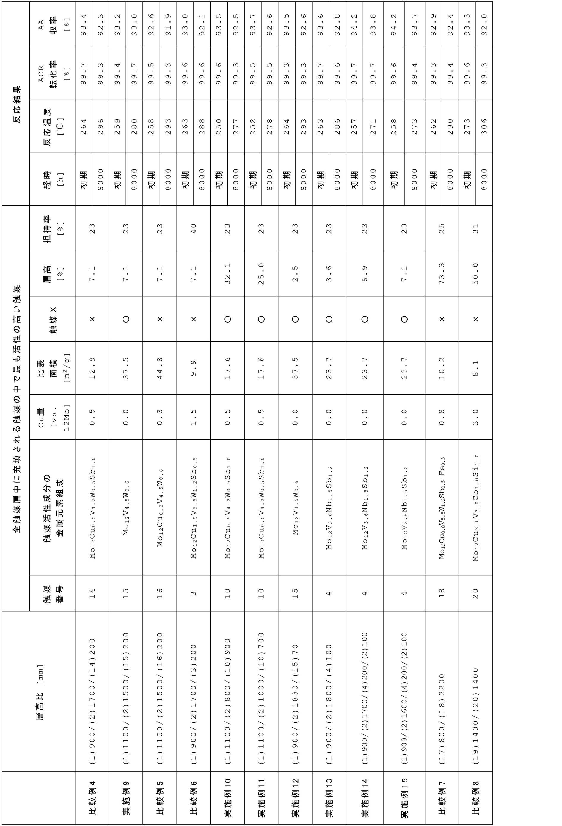
11 触媒層最前端部、
12 触媒層最後端部、
21 全触媒層、
22 触媒Xとは異なる種類の触媒を含む触媒層、
23 触媒Xを含む触媒層、
24 触媒Xとは異なる種類の触媒を含む触媒層、
31 触媒層最後端部からガス入口側に向かって全触媒層の長さの30%までの領域、L 領域31の端部。
Claims (4)
- 反応管の管軸方向に2層以上の触媒層が形成されるように活性の異なる触媒を充填した固定床反応器にアクロレインを含有するガスを供給し、前記アクロレインを気相接触酸化してアクリル酸を製造する製造方法であって、
全触媒層のガス出口側最後部からガス入口側に向かって、前記全触媒層の長さの30%までの領域の全てまたは一部に、前記全触媒層中に充填される触媒の中で最も活性の高い触媒Xを配置し、
前記触媒X中の触媒活性成分xが、MoとVと任意にCuとを有し、Cuを含む場合、Mo12モルに対して0.8モル以下であり、
前記触媒活性成分xの比表面積が、15m2/g~40m2/gである、アクリル酸の製造方法。 - 前記触媒活性成分xの組成(ただし、酸化状態を表す酸素を除く)が、下記一般式(1):
Mo12CuaVbAcBdCeDfEg (1)
(式中、Moはモリブデンであり、Cuは銅であり、Vはバナジウムであり、Aはニオブ、タングステンおよびタンタルから選ばれる少なくとも1種の元素であり、Bはアンチモンおよびテルルから選ばれる少なくとも1種の元素であり、Cはクロム、マンガン、鉄、コバルト、ニッケル、亜鉛、ビスマス、スズ、タリウムおよび希土類元素から選ばれる少なくとも1種の元素であり、Dはアルカリ金属およびアルカリ土類金属から選ばれる少なくとも1種の元素であり、Eはケイ素、アルミニウム、チタン、ジルコニウム、およびセリウムから選ばれる少なくとも1種の元素であり、a、b、c、d、e、fおよびgはCu、V、A、B、C、DおよびEの原子数を表し、0≦a≦0.8、2≦b≦10、0≦c≦12、0≦d≦6、0≦e≦12、0≦f≦5、0≦g≦50である)
で表される、請求項1に記載のアクリル酸の製造方法。 - 前記触媒活性成分x中のCu量が、Mo12モルに対して0.6モル以下である、請求項1または2記載のアクリル酸の製造方法。
- 前記触媒Xを含む触媒層の層長が、前記全触媒層の長さの3~30%である、請求項1~3のいずれか1項に記載のアクリル酸の製造方法。
Priority Applications (5)
| Application Number | Priority Date | Filing Date | Title |
|---|---|---|---|
| KR1020227023855A KR102725875B1 (ko) | 2020-01-14 | 2021-01-05 | 아크릴산의 제조 방법 |
| EP21740743.6A EP4092010A4 (en) | 2020-01-14 | 2021-01-05 | Method for producing acrylic acid |
| JP2021571145A JP7284295B2 (ja) | 2020-01-14 | 2021-01-05 | アクリル酸の製造方法 |
| CN202180009365.9A CN114981237B (zh) | 2020-01-14 | 2021-01-05 | 丙烯酸的制造方法 |
| US17/758,486 US20220402849A1 (en) | 2020-01-14 | 2021-01-05 | Method for producing acrylic acid |
Applications Claiming Priority (2)
| Application Number | Priority Date | Filing Date | Title |
|---|---|---|---|
| JP2020-003870 | 2020-01-14 | ||
| JP2020003870 | 2020-01-14 |
Publications (1)
| Publication Number | Publication Date |
|---|---|
| WO2021145233A1 true WO2021145233A1 (ja) | 2021-07-22 |
Family
ID=76863759
Family Applications (1)
| Application Number | Title | Priority Date | Filing Date |
|---|---|---|---|
| PCT/JP2021/000088 Ceased WO2021145233A1 (ja) | 2020-01-14 | 2021-01-05 | アクリル酸の製造方法 |
Country Status (7)
| Country | Link |
|---|---|
| US (1) | US20220402849A1 (ja) |
| EP (1) | EP4092010A4 (ja) |
| JP (1) | JP7284295B2 (ja) |
| KR (1) | KR102725875B1 (ja) |
| CN (1) | CN114981237B (ja) |
| TW (1) | TWI794721B (ja) |
| WO (1) | WO2021145233A1 (ja) |
Families Citing this family (1)
| Publication number | Priority date | Publication date | Assignee | Title |
|---|---|---|---|---|
| EP4428972A4 (en) | 2022-09-02 | 2025-07-02 | Lg Energy Solution Ltd | PLASMA TREATMENT APPARATUS AND LAMINATING SYSTEM FOR SECONDARY BATTERY COMPRISING SAME |
Citations (4)
| Publication number | Priority date | Publication date | Assignee | Title |
|---|---|---|---|---|
| JPH05213813A (ja) * | 1992-02-10 | 1993-08-24 | Nippon Shokubai Co Ltd | メタクリル酸の製造方法 |
| JPH0710802A (ja) * | 1993-06-28 | 1995-01-13 | Sumitomo Chem Co Ltd | アクリル酸の製造方法 |
| JP2005224660A (ja) * | 2004-02-10 | 2005-08-25 | Nippon Shokubai Co Ltd | アクロレインの接触気相酸化反応用触媒、及び該触媒を用いた接触気相酸化方法によるアクリル酸の製造方法 |
| JP2020003870A (ja) | 2018-06-25 | 2020-01-09 | キヤノン株式会社 | 画像処理装置、画像処理方法 |
Family Cites Families (9)
| Publication number | Priority date | Publication date | Assignee | Title |
|---|---|---|---|---|
| JP3943284B2 (ja) * | 1999-05-27 | 2007-07-11 | 株式会社日本触媒 | アクリル酸の製造方法 |
| JP3767309B2 (ja) | 2000-03-07 | 2006-04-19 | 住友化学株式会社 | ヘテロポリ酸系触媒の製造方法およびメタクリル酸の製造方法 |
| JP5134745B2 (ja) * | 2001-09-19 | 2013-01-30 | 株式会社日本触媒 | アクリル酸の製造方法 |
| EP1460053A4 (en) * | 2001-12-27 | 2006-03-22 | Mitsubishi Chem Corp | VAPOR CATALYST OXIDATION PROCESS AND PROCESS FOR PRODUCING (METH) ACROLEIN OR (METH) ACRYLIC ACID |
| KR100714606B1 (ko) * | 2005-02-25 | 2007-05-07 | 주식회사 엘지화학 | 불포화 알데히드 및/또는 불포화 산의 제조방법 |
| KR100868454B1 (ko) * | 2005-07-08 | 2008-11-11 | 주식회사 엘지화학 | 고정층 촉매 부분산화 반응기에서 고효율의 불포화산의제조방법 |
| JP5680373B2 (ja) * | 2010-11-01 | 2015-03-04 | 日本化薬株式会社 | 触媒及びアクリル酸の製造方法 |
| EP2671862B1 (en) * | 2011-02-02 | 2018-01-10 | Nipponkayaku Kabushikikaisha | Method for producing unsaturated aldehyde and/or unsaturated carboxylic acid |
| CA3058093A1 (en) * | 2017-03-27 | 2018-10-04 | Mitsubishi Chemical Corporation | Catalyst and catalyst group |
-
2021
- 2021-01-05 JP JP2021571145A patent/JP7284295B2/ja active Active
- 2021-01-05 US US17/758,486 patent/US20220402849A1/en active Pending
- 2021-01-05 CN CN202180009365.9A patent/CN114981237B/zh active Active
- 2021-01-05 KR KR1020227023855A patent/KR102725875B1/ko active Active
- 2021-01-05 EP EP21740743.6A patent/EP4092010A4/en active Pending
- 2021-01-05 WO PCT/JP2021/000088 patent/WO2021145233A1/ja not_active Ceased
- 2021-01-07 TW TW110100653A patent/TWI794721B/zh active
Patent Citations (4)
| Publication number | Priority date | Publication date | Assignee | Title |
|---|---|---|---|---|
| JPH05213813A (ja) * | 1992-02-10 | 1993-08-24 | Nippon Shokubai Co Ltd | メタクリル酸の製造方法 |
| JPH0710802A (ja) * | 1993-06-28 | 1995-01-13 | Sumitomo Chem Co Ltd | アクリル酸の製造方法 |
| JP2005224660A (ja) * | 2004-02-10 | 2005-08-25 | Nippon Shokubai Co Ltd | アクロレインの接触気相酸化反応用触媒、及び該触媒を用いた接触気相酸化方法によるアクリル酸の製造方法 |
| JP2020003870A (ja) | 2018-06-25 | 2020-01-09 | キヤノン株式会社 | 画像処理装置、画像処理方法 |
Non-Patent Citations (1)
| Title |
|---|
| See also references of EP4092010A4 |
Also Published As
| Publication number | Publication date |
|---|---|
| KR20220111700A (ko) | 2022-08-09 |
| TWI794721B (zh) | 2023-03-01 |
| JPWO2021145233A1 (ja) | 2021-07-22 |
| CN114981237B (zh) | 2024-04-30 |
| EP4092010A4 (en) | 2024-02-14 |
| CN114981237A (zh) | 2022-08-30 |
| EP4092010A1 (en) | 2022-11-23 |
| KR102725875B1 (ko) | 2024-11-01 |
| US20220402849A1 (en) | 2022-12-22 |
| TW202136191A (zh) | 2021-10-01 |
| JP7284295B2 (ja) | 2023-05-30 |
Similar Documents
| Publication | Publication Date | Title |
|---|---|---|
| US9079840B2 (en) | Process for producing geometric shaped catalyst bodies | |
| JP4318367B2 (ja) | アクロレインおよびアクリル酸の製造方法 | |
| JP5628936B2 (ja) | 不飽和カルボン酸製造用触媒および該触媒を用いる不飽和カルボン酸の製造方法 | |
| JP2011074085A (ja) | プロペンをアクリル酸に接触気相酸化する方法 | |
| JP4813758B2 (ja) | 複合酸化物触媒およびそれを用いたアクリル酸の製造方法 | |
| JP6831920B2 (ja) | 不飽和アルデヒド及び不飽和カルボン酸の少なくとも一方の製造方法並びに不飽和アルデヒド及び不飽和カルボン酸の少なくとも一方の製造用触媒 | |
| JPWO2012036038A1 (ja) | 不飽和アルデヒドおよび/または不飽和カルボン酸製造用触媒および該触媒を用いる不飽和アルデヒドおよび/または不飽和カルボン酸の製造方法 | |
| TW583022B (en) | Process for producing acrylic acid | |
| JP5548132B2 (ja) | アクリル酸製造用の触媒および該触媒を用いたアクリル酸の製造方法 | |
| KR101558941B1 (ko) | 메타크롤레인 및/또는 메타크릴산의 제조 방법 | |
| KR102725875B1 (ko) | 아크릴산의 제조 방법 | |
| JP3342794B2 (ja) | メタクロレイン及びメタクリル酸合成用担持触媒の製造法 | |
| JP7705342B2 (ja) | アクロレインおよびアクリル酸製造用触媒の製造方法ならびに該触媒を用いたアクロレインおよびアクリル酸の製造方法 | |
| JP4950986B2 (ja) | メタクロレイン及び/又はメタクリル酸の製造法 | |
| JPH06192144A (ja) | メタクロレイン及びメタクリル酸の製造方法 | |
| JP7224351B2 (ja) | 触媒及びそれを用いた化合物の製造方法 | |
| CN102992978A (zh) | 丙烯醛的制备方法 | |
| JP4606897B2 (ja) | 流動層アンモ酸化プロセス用複合酸化物触媒の製造方法 | |
| JP2695480B2 (ja) | メタクリル酸製造用触媒およびその製造方法 | |
| JP2009084167A (ja) | アクロレインおよび/またはアクリル酸の製造方法 | |
| JP2007326036A (ja) | 酸化又はアンモ酸化用酸化物触媒 | |
| JP2011102249A (ja) | アクリル酸の製造方法 | |
| JP2011102248A (ja) | アクリル酸の製造方法 |
Legal Events
| Date | Code | Title | Description |
|---|---|---|---|
| 121 | Ep: the epo has been informed by wipo that ep was designated in this application |
Ref document number: 21740743 Country of ref document: EP Kind code of ref document: A1 |
|
| ENP | Entry into the national phase |
Ref document number: 2021571145 Country of ref document: JP Kind code of ref document: A |
|
| ENP | Entry into the national phase |
Ref document number: 20227023855 Country of ref document: KR Kind code of ref document: A |
|
| NENP | Non-entry into the national phase |
Ref country code: DE |
|
| ENP | Entry into the national phase |
Ref document number: 2021740743 Country of ref document: EP Effective date: 20220816 |