WO2021145248A1 - Snを含む硫化物系固体電解質の製造方法 - Google Patents
Snを含む硫化物系固体電解質の製造方法 Download PDFInfo
- Publication number
- WO2021145248A1 WO2021145248A1 PCT/JP2021/000182 JP2021000182W WO2021145248A1 WO 2021145248 A1 WO2021145248 A1 WO 2021145248A1 JP 2021000182 W JP2021000182 W JP 2021000182W WO 2021145248 A1 WO2021145248 A1 WO 2021145248A1
- Authority
- WO
- WIPO (PCT)
- Prior art keywords
- solution
- organic solvent
- solid electrolyte
- sulfide
- based solid
- Prior art date
- Legal status (The legal status is an assumption and is not a legal conclusion. Google has not performed a legal analysis and makes no representation as to the accuracy of the status listed.)
- Ceased
Links
Images
Classifications
-
- H—ELECTRICITY
- H01—ELECTRIC ELEMENTS
- H01B—CABLES; CONDUCTORS; INSULATORS; SELECTION OF MATERIALS FOR THEIR CONDUCTIVE, INSULATING OR DIELECTRIC PROPERTIES
- H01B1/00—Conductors or conductive bodies characterised by the conductive materials; Selection of materials as conductors
- H01B1/06—Conductors or conductive bodies characterised by the conductive materials; Selection of materials as conductors mainly consisting of other non-metallic substances
- H01B1/10—Conductors or conductive bodies characterised by the conductive materials; Selection of materials as conductors mainly consisting of other non-metallic substances sulfides
-
- C—CHEMISTRY; METALLURGY
- C01—INORGANIC CHEMISTRY
- C01B—NON-METALLIC ELEMENTS; COMPOUNDS THEREOF; METALLOIDS OR COMPOUNDS THEREOF NOT COVERED BY SUBCLASS C01C
- C01B17/00—Sulfur; Compounds thereof
- C01B17/22—Alkali metal sulfides or polysulfides
-
- C—CHEMISTRY; METALLURGY
- C01—INORGANIC CHEMISTRY
- C01B—NON-METALLIC ELEMENTS; COMPOUNDS THEREOF; METALLOIDS OR COMPOUNDS THEREOF NOT COVERED BY SUBCLASS C01C
- C01B25/00—Phosphorus; Compounds thereof
- C01B25/08—Other phosphides
- C01B25/081—Other phosphides of alkali metals, alkaline-earth metals or magnesium
-
- C—CHEMISTRY; METALLURGY
- C01—INORGANIC CHEMISTRY
- C01B—NON-METALLIC ELEMENTS; COMPOUNDS THEREOF; METALLOIDS OR COMPOUNDS THEREOF NOT COVERED BY SUBCLASS C01C
- C01B25/00—Phosphorus; Compounds thereof
- C01B25/08—Other phosphides
- C01B25/088—Other phosphides containing plural metal
-
- C—CHEMISTRY; METALLURGY
- C01—INORGANIC CHEMISTRY
- C01B—NON-METALLIC ELEMENTS; COMPOUNDS THEREOF; METALLOIDS OR COMPOUNDS THEREOF NOT COVERED BY SUBCLASS C01C
- C01B25/00—Phosphorus; Compounds thereof
- C01B25/14—Sulfur, selenium, or tellurium compounds of phosphorus
-
- C—CHEMISTRY; METALLURGY
- C01—INORGANIC CHEMISTRY
- C01B—NON-METALLIC ELEMENTS; COMPOUNDS THEREOF; METALLOIDS OR COMPOUNDS THEREOF NOT COVERED BY SUBCLASS C01C
- C01B33/00—Silicon; Compounds thereof
- C01B33/06—Metal silicides
-
- H—ELECTRICITY
- H01—ELECTRIC ELEMENTS
- H01M—PROCESSES OR MEANS, e.g. BATTERIES, FOR THE DIRECT CONVERSION OF CHEMICAL ENERGY INTO ELECTRICAL ENERGY
- H01M10/00—Secondary cells; Manufacture thereof
- H01M10/05—Accumulators with non-aqueous electrolyte
- H01M10/052—Li-accumulators
-
- H—ELECTRICITY
- H01—ELECTRIC ELEMENTS
- H01M—PROCESSES OR MEANS, e.g. BATTERIES, FOR THE DIRECT CONVERSION OF CHEMICAL ENERGY INTO ELECTRICAL ENERGY
- H01M10/00—Secondary cells; Manufacture thereof
- H01M10/05—Accumulators with non-aqueous electrolyte
- H01M10/056—Accumulators with non-aqueous electrolyte characterised by the materials used as electrolytes, e.g. mixed inorganic/organic electrolytes
- H01M10/0561—Accumulators with non-aqueous electrolyte characterised by the materials used as electrolytes, e.g. mixed inorganic/organic electrolytes the electrolyte being constituted of inorganic materials only
- H01M10/0562—Solid materials
-
- C—CHEMISTRY; METALLURGY
- C01—INORGANIC CHEMISTRY
- C01P—INDEXING SCHEME RELATING TO STRUCTURAL AND PHYSICAL ASPECTS OF SOLID INORGANIC COMPOUNDS
- C01P2002/00—Crystal-structural characteristics
- C01P2002/70—Crystal-structural characteristics defined by measured X-ray, neutron or electron diffraction data
- C01P2002/72—Crystal-structural characteristics defined by measured X-ray, neutron or electron diffraction data by d-values or two theta-values, e.g. as X-ray diagram
-
- C—CHEMISTRY; METALLURGY
- C01—INORGANIC CHEMISTRY
- C01P—INDEXING SCHEME RELATING TO STRUCTURAL AND PHYSICAL ASPECTS OF SOLID INORGANIC COMPOUNDS
- C01P2002/00—Crystal-structural characteristics
- C01P2002/70—Crystal-structural characteristics defined by measured X-ray, neutron or electron diffraction data
- C01P2002/74—Crystal-structural characteristics defined by measured X-ray, neutron or electron diffraction data by peak-intensities or a ratio thereof only
-
- C—CHEMISTRY; METALLURGY
- C01—INORGANIC CHEMISTRY
- C01P—INDEXING SCHEME RELATING TO STRUCTURAL AND PHYSICAL ASPECTS OF SOLID INORGANIC COMPOUNDS
- C01P2002/00—Crystal-structural characteristics
- C01P2002/70—Crystal-structural characteristics defined by measured X-ray, neutron or electron diffraction data
- C01P2002/77—Crystal-structural characteristics defined by measured X-ray, neutron or electron diffraction data by unit-cell parameters, atom positions or structure diagrams
-
- C—CHEMISTRY; METALLURGY
- C01—INORGANIC CHEMISTRY
- C01P—INDEXING SCHEME RELATING TO STRUCTURAL AND PHYSICAL ASPECTS OF SOLID INORGANIC COMPOUNDS
- C01P2006/00—Physical properties of inorganic compounds
- C01P2006/40—Electric properties
-
- H—ELECTRICITY
- H01—ELECTRIC ELEMENTS
- H01M—PROCESSES OR MEANS, e.g. BATTERIES, FOR THE DIRECT CONVERSION OF CHEMICAL ENERGY INTO ELECTRICAL ENERGY
- H01M10/00—Secondary cells; Manufacture thereof
- H01M10/05—Accumulators with non-aqueous electrolyte
- H01M10/052—Li-accumulators
- H01M10/0525—Rocking-chair batteries, i.e. batteries with lithium insertion or intercalation in both electrodes; Lithium-ion batteries
-
- H—ELECTRICITY
- H01—ELECTRIC ELEMENTS
- H01M—PROCESSES OR MEANS, e.g. BATTERIES, FOR THE DIRECT CONVERSION OF CHEMICAL ENERGY INTO ELECTRICAL ENERGY
- H01M2300/00—Electrolytes
- H01M2300/0017—Non-aqueous electrolytes
- H01M2300/0065—Solid electrolytes
- H01M2300/0068—Solid electrolytes inorganic
-
- Y—GENERAL TAGGING OF NEW TECHNOLOGICAL DEVELOPMENTS; GENERAL TAGGING OF CROSS-SECTIONAL TECHNOLOGIES SPANNING OVER SEVERAL SECTIONS OF THE IPC; TECHNICAL SUBJECTS COVERED BY FORMER USPC CROSS-REFERENCE ART COLLECTIONS [XRACs] AND DIGESTS
- Y02—TECHNOLOGIES OR APPLICATIONS FOR MITIGATION OR ADAPTATION AGAINST CLIMATE CHANGE
- Y02E—REDUCTION OF GREENHOUSE GAS [GHG] EMISSIONS, RELATED TO ENERGY GENERATION, TRANSMISSION OR DISTRIBUTION
- Y02E60/00—Enabling technologies; Technologies with a potential or indirect contribution to GHG emissions mitigation
- Y02E60/10—Energy storage using batteries
-
- Y—GENERAL TAGGING OF NEW TECHNOLOGICAL DEVELOPMENTS; GENERAL TAGGING OF CROSS-SECTIONAL TECHNOLOGIES SPANNING OVER SEVERAL SECTIONS OF THE IPC; TECHNICAL SUBJECTS COVERED BY FORMER USPC CROSS-REFERENCE ART COLLECTIONS [XRACs] AND DIGESTS
- Y02—TECHNOLOGIES OR APPLICATIONS FOR MITIGATION OR ADAPTATION AGAINST CLIMATE CHANGE
- Y02P—CLIMATE CHANGE MITIGATION TECHNOLOGIES IN THE PRODUCTION OR PROCESSING OF GOODS
- Y02P70/00—Climate change mitigation technologies in the production process for final industrial or consumer products
- Y02P70/50—Manufacturing or production processes characterised by the final manufactured product
Definitions
- the present invention relates to a method for producing a sulfide-based solid electrolyte containing Sn.
- lithium-ion secondary batteries In recent years, the demand for lithium-ion secondary batteries has been increasing in applications such as personal digital assistants, portable electronic devices, electric vehicles, hybrid electric vehicles, and stationary power storage systems.
- the current lithium ion secondary battery uses a flammable organic solvent as the electrolytic solution, and requires a strong exterior so that the organic solvent does not leak.
- the structure of the equipment such as the need to take a structure to prepare for the risk of leakage of the electrolytic solution.
- Non-Patent Document 1 Non-Patent Document 1
- Patent Document 1 a method for producing a solid electrolyte, a method of reacting while pulverizing a raw material by using a ball mill, a vibration mill or the like is known. Recently, a method for synthesizing a solid electrolyte in a solvent has been developed (Patent Document 1). Synthesis in a solvent is highly productive and is expected. Conventional sulfide-based solid electrolytes containing Sn often use SnS 2 , which is a sulfide of Sn, as a raw material. However, SnS 2 has poor solubility in a solvent. Therefore, in the synthesis in a solvent, it is difficult to uniformly disperse Sn in the solid electrolyte at the time of synthesis, and there is a problem that it is difficult to obtain a solid electrolyte showing stable performance.
- Li-Sn-S containing at least lithium (Li) element, tin (Sn) element, and sulfur (S) element in the organic solvent We obtained the unexpected finding that a homogeneous solution can be prepared and used as a raw material to stably produce a sulfide-based solid electrolyte with few impurities.
- the present invention is as follows.
- the solution step 1 is a solution step 1 in which a Li-PS uniform solution is prepared by mixing Li 2 S and P 2 S 5 in the organic solvent, and at least in the organic solvent.
- a solution step 2 for preparing a Li—Sn—S uniform solution containing a lithium (Li) element, a tin (Sn) element, and a sulfur (S) element Including a solution step 2 for preparing a Li—Sn—S uniform solution containing a lithium (Li) element, a tin (Sn) element, and a sulfur (S) element.
- the method for producing a sulfide-based solid electrolyte according to ⁇ 1> which comprises mixing the Li—P—S homogeneous solution and the Li—Sn—S homogeneous solution to prepare a homogeneous solution.
- the solution step 1 is a solution step 1 in which a Li-PS uniform solution is prepared by mixing Li 2 S and P 2 S 5 in the organic solvent, and at least in the organic solvent.
- the sulfide-based solid electrolyte according to ⁇ 1> above which comprises mixing the Li—P—S homogeneous solution, the Li—Sn—S homogeneous solution, and the Li—S homogeneous solution to prepare a homogeneous solution. It is a manufacturing method of.
- the solution step 1 is a solution step 1 in which a Li-PS uniform solution is prepared by mixing Li 2 S and P 2 S 5 in the organic solvent, and at least in the organic solvent.
- lithium (Li) element and the solution step 2 of preparing tin (Sn) element, and a Li-Sn-S homogeneous solution containing sulfur (S) element, is mixed with Li 2 S and S in the organic solvent
- step 4 Li 2 S, by mixing SiS 2, and S in the organic solvent, comprising preparing a Li-SiS homogeneous solution, according to the ⁇ 4>
- This is a method for producing a sulfide-based solid electrolyte.
- Slurry step 1 for preparing a slurry liquid containing Li 3 PS 4 and A solution step for preparing a Li—Sn—S homogeneous solution containing at least lithium (Li) element, tin (Sn) element, and sulfur (S) element in an organic solvent, and a solution step.
- the slurrying step 2 in which the Li 3 PS 4 containing slurry solution and the Li—Sn—S uniform solution are mixed to prepare a mixed slurry solution, and A drying step of removing the organic solvent from the mixed slurry liquid to obtain a precursor, and A method for producing a sulfide-based solid electrolyte, which comprises a heat treatment step of heat-treating the precursor to obtain a sulfide-based solid electrolyte.
- ⁇ 9> The sulfide-based solid according to any one of ⁇ 1> to ⁇ 8> above, wherein the organic solvent is at least one selected from the group consisting of an ether solvent, a nitrile solvent, and an ester solvent. This is a method for producing an electrolyte.
- ⁇ 10> The sulfide-based solid electrolyte according to any one of ⁇ 1> to ⁇ 9> above, wherein the organic solvent is at least one selected from the group consisting of tetrahydrofuran, acetonitrile, ethyl acetate, and methyl acetate. It is a manufacturing method.
- ⁇ 11> The method for producing a sulfide-based solid electrolyte according to any one of ⁇ 1> to ⁇ 10> above, wherein the temperature in the drying step is 60 to 280 ° C. ⁇ 12>
- a method for producing a sulfide-based solid electrolyte which is excellent in productivity, has few impurities, and exhibits stable performance.
- a sulfide-based solid electrolyte exhibiting high ionic conductivity can be produced by synthesizing using a Li—Sn—S uniform solution as compared with the case of using SnS 2 , which is an insoluble raw material.
- this manufacturing method can be applied to mass production.
- the first embodiment of the present invention comprises a solution step of preparing a uniform solution containing at least lithium (Li) element, tin (Sn) element, phosphorus (P) element, and sulfur (S) element in an organic solvent.
- a drying step of removing the organic solvent from the uniform solution to obtain a precursor and
- a method for producing a sulfide-based solid electrolyte which comprises a heat treatment step of heat-treating the precursor to obtain a sulfide-based solid electrolyte.
- a homogeneous solution containing at least lithium (Li) element, tin (Sn) element, phosphorus (P) element, and sulfur (S) element in an organic solvent is a uniform solution containing at least lithium (Li) element in an organic solvent.
- Tin (Sn) element, phosphorus (P) element, and sulfur (S) element defined as an undissolved, precipitation-free solution.
- the solution step 1 is a solution step 1 in which a Li-PS uniform solution is prepared by mixing Li 2 S and P 2 S 5 in the organic solvent.
- the Li-PS includes a solution step 2 for preparing a Li—Sn—S homogeneous solution containing at least a lithium (Li) element, a tin (Sn) element, and a sulfur (S) element in the organic solvent. It is preferable to include mixing the homogeneous solution and the Li—Sn—S homogeneous solution to prepare a homogeneous solution. Further, in the first embodiment of the present invention, the solution step prepares a Li—S uniform solution by mixing Li 2 S and S in the organic solvent in addition to the solution steps 1 and 2.
- the solution step 3 to be prepared is included, and the uniform solution is prepared by mixing the Li-PS uniform solution, the Li-Sn-S uniform solution, and the Li-S uniform solution.
- the solution step in addition to the solution steps 1 to 3, at least lithium (Li) element, silicon (Si) element, and sulfur (S) are contained in the organic solvent.
- the "Li-PS uniform solution” is a solution containing at least lithium (Li) element, phosphorus (P) element, and sulfur (S) element in an organic solvent and having no undissolved precipitate.
- a “Li-Sn-S uniform solution” is defined as a solution containing at least lithium (Li) element, tin (Sn) element, and sulfur (S) element in an organic solvent and having no undissolved precipitate. Will be done.
- Li-S uniform solution is defined as a solution containing at least a lithium (Li) element and a sulfur (S) element in an organic solvent and having no undissolved precipitate.
- Li-Si-S uniform solution is defined as a solution containing at least lithium (Li) element, silicon (Si) element, and sulfur (S) element in an organic solvent and having no undissolved precipitate.
- the solution step 1 is a step of preparing a Li—P—S uniform solution by mixing Li 2 S and P 2 S 5 in an organic solvent.
- the substrate is in a slurry state in which the substrate is dispersed, but the reaction eventually occurs. No special stirring operation is required to crush the particles, and it is sufficient to provide stirring power sufficient to suspend and disperse the slurry.
- the reaction temperature in the solution step 1 the reaction proceeds slowly even at room temperature, but it can also be heated to increase the reaction rate.
- the reaction time in the solution step 1 varies depending on the type of the organic solvent, the particle size and the concentration of the raw material, but the reaction can be completed and the solution can be formed by, for example, 0.1 to 24 hours.
- This solution may contain unreacted Li 2 S and P 2 S 5.
- impurities mixed from Li 2 S and P 2 S 5 may be contained. Since impurities are hardly dissolved in the solvent and most of them precipitate, the obtained solution is filtered or centrifuged to remove the precipitate, and the solution is separated to make high-purity Li-PS uniform. It is preferable to obtain a solution.
- Li 2 S can be used as a synthetic product or a commercially available product. Since the mixing of water deteriorates other raw materials and precursors, the water content is preferably low, more preferably 300 ppm or less, and particularly preferably 50 ppm or less. Particle size of the Li 2 S is preferred because the smaller the reaction rate is faster.
- the diameter of the particles is preferably in the range of 10 nm to 100 ⁇ m, more preferably 100 nm to 30 ⁇ m, and particularly preferably in the range of 300 nm to 10 ⁇ m.
- the particle size can be measured by SEM or a particle size distribution measuring device by laser scattering. Incidentally, it is possible to preferably use the same as the Li 2 S used in a solution step 2-4 to be described later.
- P 2 S 5 can be used as a synthetic product or a commercially available product. Write purity of P 2 S 5 is high is preferable because of the impurities mixed in the solid electrolyte is reduced.
- the diameter of the particles is preferably in the range of 10 nm to 100 ⁇ m, more preferably 100 nm to 30 ⁇ m, and particularly preferably in the range of 300 nm to 10 ⁇ m.
- the mixing of water is preferably low, more preferably 300 ppm or less, and particularly preferably 50 ppm or less, because it deteriorates other raw materials and precursors.
- the organic solvent is not particularly limited as long as it is an organic solvent that does not react with Li 2 S and P 2 S 5.
- an ether solvent, an ester solvent, a hydrocarbon solvent, a nitrile solvent and the like can be mentioned. Specific examples thereof include tetrahydrofuran, cyclopentyl methyl ether, diisopropyl ether, diethyl ether, dimethyl ether, dioxane, methyl acetate, ethyl acetate, butyl acetate and acetonitrile.
- At least one selected from the group consisting of tetrahydrofuran, acetonitrile, ethyl acetate, and methyl acetate is preferable, and acetonitrile is particularly preferable. Since acetonitrile does not contain oxygen atoms in its structure, it is difficult for oxygen to be introduced into the raw material composition, and deterioration is suppressed. Further, in order to prevent the raw material composition from deteriorating, it is preferable to remove oxygen and water in the organic solvent, and in particular, the water content is preferably 100 ppm or less, more preferably 50 ppm or less. As the organic solvent used in the solvation steps 2 to 4 described later, the same organic solvent as described above can be preferably used.
- the solution step 2 is a step of preparing a Li—Sn—S homogeneous solution containing at least a lithium (Li) element, a tin (Sn) element, and a sulfur (S) element in an organic solvent.
- the solution of step 2 Li 2 S, SnS, and by mixing S (the elemental sulfur) in an organic solvent to prepare a Li-SnS homogeneous solution.
- Conventional sulfide-based solid electrolytes containing Sn often use SnS 2 , which is a sulfide of Sn, as a raw material.
- SnS 2 has poor solubility in a solvent.
- the present inventors have, Li 2 S, by using a combination of SnS, and S, they found that it is possible to prepare the Li-SnS homogeneous solution in an organic solvent.
- the substrate is in a slurry state in which the substrate is dispersed, but the reaction eventually occurs. No special stirring operation is required to crush the particles, and it is sufficient to provide stirring power sufficient to suspend and disperse the slurry.
- reaction temperature in the solution step 2 is lower than the boiling point of the organic solvent, and although it depends on the organic solvent used, it is usually less than 120 ° C.
- the preferred reaction temperature is 50-100 ° C, more preferably 60-90 ° C. It is possible to carry out the process under pressure using an autoclave or the like, but if mixing is performed at a high temperature of 120 ° C. or higher, there is a concern that side reactions will proceed.
- the reaction time in the solution step 2 varies depending on the type of the organic solvent, the particle size and the concentration of the raw material, but the reaction can be completed and the solution can be formed by, for example, 0.1 to 24 hours.
- the solution may include Li 2 S and SnS and S unreacted. It may also contain impurities mixed from Li 2 S and SnS and S. Since impurities are hardly dissolved in the solvent and most of them precipitate, the obtained solution is filtered or centrifuged to remove the precipitate, and the solution is separated to make high-purity Li-Sn-S uniform. It is preferable to obtain a solution.
- SnS can be used as a synthetic product or a commercially available product.
- the diameter of the particles is preferably in the range of 10 nm to 100 ⁇ m, more preferably 100 nm to 30 ⁇ m, and particularly preferably in the range of 300 nm to 10 ⁇ m.
- the particle size can be measured by SEM or a particle size distribution measuring device by laser scattering. Even if some of the above raw materials are amorphous, they can be used without any problem.
- the mixing of water is preferably low, more preferably 300 ppm or less, and particularly preferably 50 ppm or less, because it deteriorates other raw materials and precursors.
- Elemental sulfur can be used in both synthetic and commercial products, but generally, cyclic S8 sulfur is used. Since the mixing of water deteriorates other raw materials and precursors, the water content is preferably low, more preferably 300 ppm or less, and particularly preferably 50 ppm or less. The smaller the particle size of elemental sulfur, the faster the reaction rate, which is preferable. The diameter of the particles is preferably in the range of 10 nm to 100 ⁇ m, more preferably 100 nm to 30 ⁇ m, and particularly preferably in the range of 300 nm to 10 ⁇ m. As the S (elemental sulfur) used in the solution-forming steps 3 and 4 described later, the same one as described above can be preferably used.
- the solution step 3 is a step of preparing a Li—S uniform solution by mixing Li 2 S and S (elemental sulfur) in an organic solvent.
- the substrate is in a slurry state in which the substrate is dispersed, but the reaction eventually occurs.
- reaction temperature in the solution step 3 is lower than the boiling point of the organic solvent, and although it varies depending on the organic solvent used, it is usually less than 120 ° C.
- the preferred reaction temperature is 50-100 ° C, more preferably 60-90 ° C. It is possible to carry out the process under pressure using an autoclave or the like, but if mixing is performed at a high temperature of 120 ° C. or higher, there is a concern that side reactions will proceed.
- the reaction time in the solution step 3 varies depending on the type of the organic solvent, the particle size and the concentration of the raw material, but the reaction can be completed and the solution can be formed by, for example, 0.1 to 24 hours.
- the solution may include Li 2 S and S unreacted. Further, impurities mixed from Li 2 S or S may be contained. Since impurities are hardly dissolved in the solvent and most of them precipitate, the obtained solution is filtered or centrifuged to remove the precipitate, and the solution is separated to obtain a high-purity uniform solution of Li-S. It is preferable to obtain.
- the solution step 4 is a step of preparing a Li—Si—S uniform solution containing at least a lithium (Li) element, a silicon (Si) element, and a sulfur (S) element in an organic solvent.
- a Li—Si—S uniform solution containing at least a lithium (Li) element, a silicon (Si) element, and a sulfur (S) element in an organic solvent.
- Li—Si—S uniform solution a sulfide-based solid electrolyte having few impurities and high ionic conductivity can be stably obtained.
- SiS 2 is used as a starting material, it is difficult to uniformly disperse Si in the solid electrolyte during synthesis.
- SiS 2 is highly reactive with the atmosphere and often contains an oxygen-containing compound or Si, which is an unreacted raw material. Therefore, SiS 2 should be prepared without impurities. Is difficult.
- the Li—Si—S uniform solution is stable because Si is likely to be uniformly dispersed in the solid electrolyte during synthesis and impurities are reduced through the subsequent operation of removing the precipitate, so that side reactions are unlikely to occur. It is considered that a sulfide-based solid electrolyte having high ionic conductivity can be produced.
- Li-SiS homogeneous solution Li 2 S, by reacting mixed in an organic solvent SiS 2 and S (elemental sulfur), Li, it is preferable that the solution Si and S are dissolved.
- This solution may contain unreacted Li 2 S, Si S 2 and S. Further, impurities mixed from Li 2 S, Si S 2 and S may be contained.
- the obtained solution is filtered or centrifuged to remove the precipitate, and the solution is separated to obtain a uniform solution of Li—Si—S.
- the precipitate can be removed by filtration or centrifugation.
- the pore size of the filter is 10 ⁇ m or less. It is more preferably 5 ⁇ m or less, and particularly preferably 2 ⁇ m or less.
- impurities include oxygen-containing compounds of Si and SiS 2 , SiO 2 and the like.
- SiS 2 can be used as a synthetic product or a commercially available product. Higher purity of SiS 2 is preferable because impurities mixed in the solid electrolyte are reduced.
- the diameter of the particles is preferably in the range of 10 nm to 100 ⁇ m, more preferably 100 nm to 30 ⁇ m, and particularly preferably in the range of 300 nm to 10 ⁇ m.
- the particle size can be measured by SEM or a particle size distribution measuring device by laser scattering. Even if some of the above raw materials are amorphous, they can be used without any problem.
- the mixing of water is preferably low, more preferably 300 ppm or less, and particularly preferably 50 ppm or less, because it deteriorates other raw materials and precursors.
- the total concentration of Li, Si and S in the organic solvent is preferably 0.5 to 20% by mass, more preferably 1 to 15% by mass, and particularly preferably 2 to 10% by mass. If the total concentration of Li, Si and S in the organic solvent is higher than 20% by mass, it becomes difficult to form a uniform solution due to the precipitation of solids. On the other hand, when the total concentration of Li, Si and S in the organic solvent is lower than 0.5% by mass, a large amount of organic solvent is used, the load of solvent recovery increases, and the reactor It causes the size to become excessively large.
- the Li-PS uniform solution obtained in the solution step 1 and the Li-Sn-S uniform solution obtained in the solution step 2 are mixed or Alternatively, (ii) the Li-PS uniform solution obtained in the solution step 1, the Li-Sn-S uniform solution obtained in the solution step 2, and the Li-S obtained in the solution step 3.
- the uniform solution is mixed, or (iii) the Li—P—S uniform solution obtained in the solution step 1 and the Li—Sn—S uniform solution obtained in the solution step 2 and the solution step. It is preferable to prepare a uniform mixed solution by mixing the Li—S uniform solution obtained in 3 and the Li—Si—S uniform solution obtained in the solution step 4.
- the type and concentration of the elements can be confirmed by, for example, an ICP emission spectrometer. Since the performance of the sulfide-based solid electrolyte changes significantly due to a slight difference in composition, it is preferable to precisely control the elemental composition by performing ICP emission analysis on a uniform solution.
- a halogen compound can also be added here. At this time, it is preferable that the halogen compound is also dissolved in the organic solvent.
- Specific examples of the halogen compound include LiCl, LiBr, LiI, PCl 5 , PCl 3 , PBr 5 and PBr 3 , and more preferably LiCl, LiBr and LiI. These may be used alone or in combination of two or more.
- the drying step is a step of obtaining a precursor by drying the obtained uniform solution to remove an organic solvent. Drying is preferably heat drying or vacuum drying in an inert gas atmosphere.
- the drying temperature is preferably in the range of 60 to 280 ° C, more preferably 100 to 250 ° C. The optimum range varies slightly depending on the type of organic solvent, but the temperature range is important. If the drying temperature is set too high in the presence of an organic solvent, the precursor will be altered in most cases. If the drying temperature is too low, the amount of residual solvent increases, and if the next heat treatment step is performed as it is, the organic solvent is carbonized and the electron conductivity of the obtained sulfide-based solid electrolyte is increased.
- the solid electrolyte used in the second part of FIG. 2 is required to have sufficiently low electron conductivity. When used for such applications, it is necessary to reduce the residual solvent as much as possible.
- the drying time varies slightly depending on the type of the organic solvent and the drying temperature, but the organic solvent can be sufficiently removed by carrying out the drying for 1 to 24 hours.
- the temperature at which the organic solvent is removed can be lowered and the required time can be reduced. Can be shortened. It is also possible to perform the subsequent heat treatment step and the drying step at the same time.
- the heat treatment step is a step of heat-treating the precursor obtained in the drying step to obtain a sulfide-based solid electrolyte.
- the heating temperature is usually preferably in the range of 200 to 700 ° C, more preferably in the range of 350 to 650 ° C, and particularly preferably in the range of 400 to 600 ° C. If the temperature is lower than the above range, desired crystals are unlikely to be formed, while if the temperature is higher than the above range, crystals other than the intended ones may be formed.
- the heating time varies slightly in relation to the heating temperature, it can usually be sufficiently crystallized in the range of 0.1 to 24 hours. Heating at a high temperature for a long time exceeding the above range is not preferable because there is a concern about deterioration of the sulfide-based solid electrolyte.
- the heating can be performed in a vacuum or in an atmosphere of an inert gas, but is preferably in an atmosphere of an inert gas.
- the inert gas nitrogen, helium, argon or the like can be used, but argon is particularly preferable. It is preferable that oxygen and water are low, and the conditions are the same as those at the time of mixing in the slurrying step.
- the second embodiment of the present invention includes a slurrying step 1 for preparing a slurry liquid containing Li 3 PS 4 and a slurrying step 1.
- the slurrying step 2 in which the Li 3 PS 4 containing slurry solution and the Li—Sn—S uniform solution are mixed to prepare a mixed slurry solution, and A drying step of removing the organic solvent from the mixed slurry liquid to obtain a precursor, and A method for producing a sulfide-based solid electrolyte, which comprises a heat treatment step of heat-treating the precursor to obtain a sulfide-based solid electrolyte.
- the other steps in the second embodiment can be performed according to the steps described in the first embodiment.
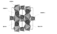
- the LGPS type crystal structure includes an octahedron O composed of Li element and S element, a tetrahedron T1 composed of one or more elements selected from the group consisting of P, Ge, Si and Sn, and an S element.
- tetrahedron composed of P element and S elements T2 and a (PS 4 3- anion) tetrahedron T1 and octahedral O share a crest tetrahedral T2 and octahedral O share a vertex crystals It is a structure.
- a solid electrolyte having an LGPS type crystal structure is more preferable because it has a particularly high ionic conductivity.
- the LGPS-based solid electrolyte containing Si tends to generate hydrogen sulfide when it comes into contact with water, but Sn does not generate hydrogen sulfide even when it comes into contact with water, and has the advantages of high safety and easy production.
- the sulfide-based solid electrolyte of the present invention obtained as described above can be made into a desired molded product by various means, and can be used for various purposes such as the all-solid-state battery described below.
- the molding method is not particularly limited. For example, a method similar to the method for molding each layer constituting the all-solid-state battery described in ⁇ All-solid-state battery> described later can be used.
- the sulfide-based solid electrolyte of the present invention can be used, for example, as a solid electrolyte for an all-solid-state battery. Further, according to a further embodiment of the present invention, an all-solid-state battery including the above-mentioned solid electrolyte for an all-solid-state battery is provided.
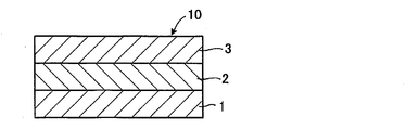
- FIG. 2 is a schematic cross-sectional view of an all-solid-state battery according to an embodiment of the present invention.
- the all-solid-state battery 10 has a structure in which the solid electrolyte layer 2 is arranged between the positive electrode layer 1 and the negative electrode layer 3.
- the all-solid-state battery 10 can be used in various devices such as mobile phones, personal computers, automobiles, and the like.
- the sulfide-based solid electrolyte of the present invention may be contained as a solid electrolyte in any one or more of the positive electrode layer 1, the negative electrode layer 3, and the solid electrolyte layer 2.
- the sulfide-based solid electrolyte of the present invention is used in combination with a known positive electrode active material or negative electrode active material for a lithium ion secondary battery. do.
- the amount ratio of the sulfide-based solid electrolyte of the present invention contained in the positive electrode layer 1 or the negative electrode layer 3 is not particularly limited.
- the sulfide-based solid electrolyte of the present invention may be composed alone, or if necessary, an oxide solid electrolyte (for example, Li 7 La 3 Zr 2 O 12 ) and a sulfide-based solid electrolyte (for example, Li 2).
- SP 2 S 5 ) and other complex sulfide solid electrolytes for example, LiBH 4 , 3LiBH 4- LiI
- the all-solid-state battery is manufactured by molding and laminating each of the above-mentioned layers, but the molding method and laminating method of each layer are not particularly limited.
- a method in which a solid electrolyte and / or an electrode active material is dispersed in a solvent to form a slurry is applied by a doctor blade or a spin coat, and the film is formed by rolling the film; vacuum deposition method, ion plating.
- Vapor deposition method in which film formation and lamination are performed using a method, sputtering method, laser ablation method, etc .; there is a pressure molding method in which powder is molded by hot pressing or cold pressing without applying temperature and then laminated. ..
- the sulfide-based solid electrolyte of the present invention is relatively soft, it is particularly preferable to form and laminate each layer by a pressure molding method to prepare an all-solid-state battery.
- a pressure forming method there are a hot press performed by heating and a cold press not heated, but a cold press can also be sufficiently formed.
- the present invention includes a molded body obtained by heat-molding the sulfide-based solid electrolyte of the present invention.
- the molded product is suitably used as an all-solid-state battery.
- the present invention also includes a method for manufacturing an all-solid-state battery, which comprises a step of heat-molding the sulfide-based solid electrolyte of the present invention.
- concentration of Li 0.5% by mass.
- ⁇ Preparation of uniform mixed solution> 6.6 g of the Li—P—S uniform solution prepared above, 25.08 g of the Li—Sn—S uniform solution, and Li—S so as to have a molar ratio of Li: Sn: P 12: 1: 3. 7.97 g of the homogeneous solution was mixed and stirred for 3 hours to prepare a homogeneous mixed solution.
- ⁇ Heat treatment process> The obtained precursor was placed in a glass reaction tube in a glove box and placed in an electric tube furnace so that the precursor was not exposed to the atmosphere. Argon (G3 grade) was blown into the reaction tube, the temperature was raised to 550 ° C over 3 hours, and then calcined at 550 ° C for 8 hours to synthesize Li 9.81 Sn 0.81 P 2.19 S 12 crystals. did.
- Example 2 ⁇ Solution step 1> The same operation as in Example 1 was carried out to obtain a Li-PS uniform solution.
- the concentration of Sn was 0.89% by mass.
- ⁇ Preparation of uniform mixed solution> 6.6 g of the Li—P—S uniform solution prepared above and 33.28 g of the Li—Sn—S uniform solution were mixed so as to have a molar ratio of Li: Sn: P 12: 1: 3, and 3 Stir for hours to prepare a homogeneous mixed solution.
- Example 1 The same operation as in Example 1 was carried out to obtain a precursor.
- ⁇ Heat treatment process> The same operation as in Example 1 was carried out to synthesize Li 9.81 Sn 0.81 P 2.19 S 12 crystals.
- Example 1 (Comparative Example 1) ⁇ Solution process> The same operation as in Example 1 was carried out to obtain a Li-PS uniform solution.
- ⁇ Drying process> The solvent was removed by drying the obtained slurry solution at 180 ° C. for 4 hours under vacuum. Solvent removal was performed with stirring the solution. Then, it cooled to room temperature to obtain a precursor.
- ⁇ Heat treatment process> The same operation as in Example 1 was carried out to synthesize Li 9.81 Sn 0.81 P 2.19 S 12 crystals.
- Example 3 ⁇ Solution step 1> The same operation as in Example 1 was carried out to obtain a Li-PS uniform solution.
- ⁇ Solution step 2> The same operation as in Example 1 was carried out to obtain a Li—Sn—S uniform solution.
- ⁇ Solution step 3> The same operation as in Example 1 was carried out to obtain a Li—S uniform solution.
- ⁇ Solution step 4> Li 2 S (manufactured by Sigma-Aldrich, purity 99.8%) so that the molar ratio of Li 2 S: SiS 2 : S 0.5: 1: 0.4 is obtained in the glove box under an argon atmosphere.
- Li—Si—S uniform solution The obtained solution was filtered using a membrane filter (PTFE, pore size 1.0 ⁇ m) to obtain 2.0 g as a filtrate and 578 g as a filtrate (Li—Si—S uniform solution).
- PTFE membrane filter
- pore size 1.0 ⁇ m a membrane filter
- Li—Si—S uniform solution the Li: Si: S (molar ratio) was 1: 1: 3.
- the concentration of (Li 2 S + SiS 2 + S) was 3.43% by mass.
- ⁇ Preparation of uniform mixed solution> 6.6 g of the Li—P—S homogeneous solution prepared above and 11.11 g of the Li—Sn—S homogeneous solution so as to have a molar ratio of Li: Sn: Si: P 38: 1: 4: 6. , 13.48 g of the Li—Si—S uniform solution and 22.93 g of the Li—S uniform solution were mixed and stirred for 3 hours to prepare a uniform mixed solution.
- ⁇ Drying process> The solvent was removed by drying the obtained homogeneous mixture solution under vacuum at 180 ° C. for 4 hours. Solvent removal was performed with stirring the solution. Then, it cooled to room temperature to obtain a precursor.
- ⁇ Heat treatment process> The obtained precursor was placed in a glass reaction tube in a glove box and placed in an electric tube furnace so that the precursor was not exposed to the atmosphere. By blowing argon (G3 grade) into the reaction tube, raising the temperature to 550 ° C over 3 hours, and then firing at 550 ° C for 8 hours, Li 10.35 Sn 0.27 Si 1.08 P 1.65 S Twelve crystals were synthesized.
- ⁇ Solution process> The same operation as in Example 1 was carried out to obtain a Li—Sn—S uniform solution.
- ⁇ Slurry process 2> 7.72 g of the Li 3 PS 4- containing slurry solution prepared above and 20.71 g of the Li—Sn—S uniform solution were mixed so as to have a molar ratio of Li: Sn: P 12: 1: 3, and 3 A slurry mixture was prepared by stirring for hours.
- X-ray diffraction measurement> X-ray diffraction measurement (“X'Pert3 Powerer” manufactured by PANalytical Co., Ltd.) was performed on the sulfide-based solid electrolyte powders obtained in Examples 1 to 4 and Comparative Examples 1 and 2 at room temperature (25 ° C.) in an Ar atmosphere. , CuK ⁇ : ⁇ 1.5405 ⁇ ). The results of X-ray diffraction measurement of the sulfide-based solid electrolytes obtained in Examples 1 to 4 and Comparative Examples 1 and 2 are shown in FIG. As shown in FIG.
Landscapes
- Chemical & Material Sciences (AREA)
- Organic Chemistry (AREA)
- Inorganic Chemistry (AREA)
- Engineering & Computer Science (AREA)
- Manufacturing & Machinery (AREA)
- Chemical Kinetics & Catalysis (AREA)
- Electrochemistry (AREA)
- General Chemical & Material Sciences (AREA)
- Physics & Mathematics (AREA)
- Condensed Matter Physics & Semiconductors (AREA)
- General Physics & Mathematics (AREA)
- Life Sciences & Earth Sciences (AREA)
- Environmental & Geological Engineering (AREA)
- General Life Sciences & Earth Sciences (AREA)
- Geology (AREA)
- Secondary Cells (AREA)
- Conductive Materials (AREA)
- Battery Electrode And Active Subsutance (AREA)
- Primary Cells (AREA)
Abstract
Description
これらの固体電解質の中で、硫化物はイオン伝導度が高く、比較的やわらかく固体-固体間の界面を形成しやすい特徴がある。活物質にも安定であり、実用的な固体電解質として開発が進んでいる。
硫化物系固体電解質の中でも、Snが含まれる硫化物系固体電解質は良好なイオン伝導度と高い耐水性が得られることが分かっており、実用化への期待が高い(非特許文献1)。
従来のSnを含んだ硫化物系固体電解質は、原料にSnの硫化物であるSnS2を用いていることが多い。しかし、SnS2は溶媒への溶解性に乏しい。そのため、溶媒中での合成において、合成時にSnを固体電解質中に均一に分散させることが困難であり、安定した性能を示す固体電解質が得られにくいという課題があった。
<1> 有機溶媒中に少なくともリチウム(Li)元素、スズ(Sn)元素、リン(P)元素、及び硫黄(S)元素を含む均一溶液を調製する溶液化工程と、
前記均一溶液から前記有機溶媒を除去して前駆体を得る乾燥工程と、
前記前駆体を加熱処理して硫化物系固体電解質を得る加熱処理工程と、を含むことを特徴とする硫化物系固体電解質の製造方法である。
<2> 前記溶液化工程が、Li2SとP2S5とを前記有機溶媒中で混合することによってLi-P-S均一溶液を調製する溶液化工程1と、前記有機溶媒中に少なくともリチウム(Li)元素、スズ(Sn)元素、及び硫黄(S)元素を含むLi-Sn-S均一溶液を調製する溶液化工程2とを含み、
前記Li-P-S均一溶液、及び前記Li-Sn-S均一溶液を混合して均一溶液を調製することを含む、上記<1>に記載の硫化物系固体電解質の製造方法である。
<3> 前記溶液化工程が、Li2SとP2S5とを前記有機溶媒中で混合することによってLi-P-S均一溶液を調製する溶液化工程1と、前記有機溶媒中に少なくともリチウム(Li)元素、スズ(Sn)元素、及び硫黄(S)元素を含むLi-Sn-S均一溶液を調製する溶液化工程2と、Li2SとSとを前記有機溶媒中で混合することによってLi-S均一溶液を調製する溶液化工程3とを含み、
前記Li-P-S均一溶液、前記Li-Sn-S均一溶液、及び前記Li-S均一溶液を混合して均一溶液を調製することを含む、上記<1>に記載の硫化物系固体電解質の製造方法である。
<4> 前記溶液化工程が、Li2SとP2S5とを前記有機溶媒中で混合することによってLi-P-S均一溶液を調製する溶液化工程1と、前記有機溶媒中に少なくともリチウム(Li)元素、スズ(Sn)元素、及び硫黄(S)元素を含むLi-Sn-S均一溶液を調製する溶液化工程2と、Li2SとSとを前記有機溶媒中で混合することによってLi-S均一溶液を調製する溶液化工程3と、前記有機溶媒中に少なくともリチウム(Li)元素、ケイ素(Si)元素、及び硫黄(S)元素を含むLi-Si-S均一溶液を調製する溶液化工程4とを含み、
前記Li-P-S均一溶液、前記Li-Sn-S均一溶液、前記Li-S均一溶液、及び前記Li-Si-S均一溶液を混合して均一溶液を調製することを含む、上記<1>に記載の硫化物系固体電解質の製造方法である。
<5> 前記溶液化工程2が、Li2S、SnS、及びSを前記有機溶媒中で混合することによって、Li-Sn-S均一溶液を調製することを含む、上記<2>から<4>のいずれかに記載の硫化物系固体電解質の製造方法である。
<6> 前記溶液化工程4が、Li2S、SiS2、及びSを前記有機溶媒中で混合することによって、Li-Si-S均一溶液を調製することを含む、上記<4>に記載の硫化物系固体電解質の製造方法である。
<7> Li3PS4含有スラリー液を調製するスラリー化工程1と、
有機溶媒中に少なくともリチウム(Li)元素、スズ(Sn)元素、及び硫黄(S)元素を含むLi-Sn-S均一溶液を調製する溶液化工程と、
前記Li3PS4含有スラリー液、及び前記Li-Sn-S均一溶液を混合し、混合スラリー液を調製するスラリー化工程2と、
前記混合スラリー液から前記有機溶媒を除去して前駆体を得る乾燥工程と、
前記前駆体を加熱処理して硫化物系固体電解質を得る加熱処理工程と、を含むことを特徴とする硫化物系固体電解質の製造方法である。
<8> 前記溶液化工程が、前記有機溶媒中にLi2S、SnS、及びSを添加して混合し、Li-Sn-S均一溶液を調製することを含む、上記<7>に記載の硫化物系固体電解質の製造方法である。
<9> 前記有機溶媒が、エーテル系溶媒、ニトリル系溶媒、及びエステル系溶媒からなる群より選ばれる少なくとも1種である、上記<1>から<8>のいずれかに記載の硫化物系固体電解質の製造方法である。
<10> 前記有機溶媒が、テトラヒドロフラン、アセトニトリル、酢酸エチル、及び酢酸メチルからなる群より選ばれる少なくとも1種である、上記<1>から<9>のいずれかに記載の硫化物系固体電解質の製造方法である。
<11> 前記乾燥工程における温度が、60~280℃である、上記<1>から<10>のいずれかに記載の硫化物系固体電解質の製造方法である。
<12> 前記加熱処理工程における温度が、200℃~700℃である、上記<1>から<11>のいずれかに記載の硫化物系固体電解質の製造方法である。
<13> 前記硫化物系固体電解質が、LGPS系固体電解質を含有し、X線回折(CuKα:λ=1.5405Å)において、少なくとも、2θ=19.90°±0.50°、20.20°±0.50°、26.70°±0.50°、及び29.20°±0.50°の位置にピークを有する、上記<1>から<12>のいずれかに記載の硫化物系固体電解質の製造方法である。
本発明の第1実施形態は、有機溶媒中に少なくともリチウム(Li)元素、スズ(Sn)元素、リン(P)元素、及び硫黄(S)元素を含む均一溶液を調製する溶液化工程と、
前記均一溶液から前記有機溶媒を除去して前駆体を得る乾燥工程と、
前記前駆体を加熱処理して硫化物系固体電解質を得る加熱処理工程と、を含むことを特徴とする硫化物系固体電解質の製造方法である。
本発明において、有機溶媒中に少なくともリチウム(Li)元素、スズ(Sn)元素、リン(P)元素、及び硫黄(S)元素を含む均一溶液とは、有機溶媒中に少なくともリチウム(Li)元素、スズ(Sn)元素、リン(P)元素、及び硫黄(S)元素を含み、未溶解の沈殿がない溶液と定義される。
また、本発明の第1実施形態は、前記溶液化工程が、上記溶液化工程1及び2に加えて、Li2SとSとを前記有機溶媒中で混合することによってLi-S均一溶液を調製する溶液化工程3を含み、前記Li-P-S均一溶液、前記Li-Sn-S均一溶液、及び前記Li-S均一溶液を混合して均一溶液を調製することを含むことも好ましい。
更に、本発明の第1実施形態は、前記溶液化工程が、上記溶液化工程1~3に加えて、前記有機溶媒中に少なくともリチウム(Li)元素、ケイ素(Si)元素、及び硫黄(S)元素を含むLi-Si-S均一溶液を調製する溶液化工程4を含み、前記Li-P-S均一溶液、前記Li-Sn-S均一溶液、前記Li-S均一溶液、及び前記Li-Si-S均一溶液を混合して均一溶液を調製することを含むことも好ましい。
本発明において、「Li-P-S均一溶液」とは、有機溶媒中に少なくともリチウム(Li)元素、リン(P)元素、及び硫黄(S)元素を含み、未溶解の沈殿がない溶液と定義される。同様に、「Li-Sn-S均一溶液」とは、有機溶媒中に少なくともリチウム(Li)元素、スズ(Sn)元素、及び硫黄(S)元素を含み、未溶解の沈殿がない溶液と定義される。また、「Li-S均一溶液」とは、有機溶媒中に少なくともリチウム(Li)元素、及び硫黄(S)元素を含み、未溶解の沈殿がない溶液と定義される。更に、「Li-Si-S均一溶液」とは、有機溶媒中に少なくともリチウム(Li)元素、ケイ素(Si)元素、及び硫黄(S)元素を含み、未溶解の沈殿がない溶液と定義される。
溶液化工程1は、Li2SとP2S5とを有機溶媒中で混合することによってLi-P-S均一溶液を調製する工程である。好ましくは、Li2SとP2S5とをLi2S/P2S5=0.7~1.5のモル比となるように有機溶媒中で混合することによってLi-P-S均一溶液を調製する。
溶液化工程1における混合の際には基質が分散されたスラリー状態であるが、やがて反応する。粒子を砕く特別な撹拌操作は不要であり、スラリーが懸濁分散できるだけの撹拌動力を与えれば十分である。
溶液化工程1における反応温度は、室温下においても反応が緩やかに進行するが、反応速度を上げるために加熱することもできる。加熱する場合には、有機溶媒の沸点以下で行うことで十分であり、使用する有機溶媒によって異なるものの、通常は120℃未満である。オートクレーブ等を用いて加圧状態で行うことも可能であるが、120℃以上の高い温度で混合を行うと、副反応が進行することが懸念される。
この溶液には、未反応のLi2SやP2S5が含まれてもよい。また、Li2SやP2S5から混入した不純物が含まれていてもよい。不純物は溶媒中にほとんど溶解せず、多くは沈殿するため、得られた溶液に対し濾過や遠心分離を行い沈殿を除去し、溶液を分離することによって、高純度なLi-P-Sの均一溶液を得ることが好ましい。
溶液化工程2は、有機溶媒中に少なくともリチウム(Li)元素、スズ(Sn)元素、及び硫黄(S)元素を含むLi-Sn-S均一溶液を調製する工程である。好ましくは、溶液化工程2は、Li2S、SnS、及びS(単体硫黄)を有機溶媒中で混合することによって、Li-Sn-S均一溶液を調製する。
従来のSnを含んだ硫化物系固体電解質は、原料にSnの硫化物であるSnS2を用いていることが多い。しかし、SnS2は溶媒への溶解性に乏しい。そのため、溶媒中での合成において、合成時にSnを固体電解質中に均一に分散させることが困難であり、安定した性能を示す固体電解質が得られにくいという課題があった。本発明者らは、Li2S、SnS、及びSの組み合わせを用いることにより、これらが有機溶媒に溶解したLi-Sn-S均一溶液を調製することができることを見出した。
溶液化工程2における混合の際には基質が分散されたスラリー状態であるが、やがて反応する。粒子を砕く特別な撹拌操作は不要であり、スラリーが懸濁分散できるだけの撹拌動力を与えれば十分である。
溶液化工程2における反応温度は、有機溶媒の沸点以下で行うことで十分であり、使用する有機溶媒によって異なるものの、通常は120℃未満である。好ましい反応温度は、50~100℃であり、より好ましくは60~90℃である。オートクレーブ等を用いて加圧状態で行うことも可能であるが、120℃以上の高い温度で混合を行うと、副反応が進行することが懸念される。
この溶液には、未反応のLi2SやSnSやSが含まれてもよい。また、Li2SやSnSやSから混入した不純物が含まれていてもよい。不純物は溶媒中にほとんど溶解せず、多くは沈殿するため、得られた溶液に対し濾過や遠心分離を行い沈殿を除去し、溶液を分離することによって、高純度なLi-Sn-Sの均一溶液を得ることが好ましい。
得られた均一溶液の各元素の濃度はICPにより分析されるが、Li:Sn:S=4:1:15~12:1:43のモル比であることが好ましく、より好ましくはLi:Sn:S=5:1:18~11:1:40であり、特に好ましくはLi:Sn:S=6:1:22~10:1:36である。
溶液化工程3は、Li2SとS(単体硫黄)とを有機溶媒中で混合することによって、Li-S均一溶液を調製する工程である。
溶液化工程3は、好ましくは、Li2SとSとをLi2S:S=1:4~1:10のモル比となるように、より好ましくは、Li2SとSとをLi2S:S=1:5~1:8のモル比となるように、有機溶媒中で混合することによってLi-S均一溶液を調製する。
溶液化工程3における混合の際には基質が分散されたスラリー状態であるが、やがて反応する。粒子を砕く特別な撹拌操作は不要であり、スラリーが懸濁分散できるだけの撹拌動力を与えれば十分である。
溶液化工程3における反応温度は、有機溶媒の沸点以下で行うことで十分であり、使用する有機溶媒によって異なるものの、通常は120℃未満である。好ましい反応温度は、50~100℃であり、より好ましくは60~90℃である。オートクレーブ等を用いて加圧状態で行うことも可能であるが、120℃以上の高い温度で混合を行うと、副反応が進行することが懸念される。
この溶液には、未反応のLi2SやSが含まれてもよい。また、Li2SやSから混入した不純物が含まれていてもよい。不純物は溶媒中にほとんど溶解せず、多くは沈殿するため、得られた溶液に対し濾過や遠心分離を行い沈殿を除去し、溶液を分離することによって、高純度なLi-Sの均一溶液を得ることが好ましい。
溶液化工程4は、有機溶媒中に少なくともリチウム(Li)元素、ケイ素(Si)元素、及び硫黄(S)元素を含むLi-Si-S均一溶液を調製する工程である。Li-Si-S均一溶液を使用することにより、不純物が少なく、高いイオン伝導度を有する硫化物系固体電解質を安定して得ることができる。SiS2を出発物質に用いる場合、合成時にSiを固体電解質中に均一に分散させることは困難である。また、SiS2は大気との反応性が高く含酸素化合物が含まれていたり、未反応の原料であるSiが含まれていることが多いなど、不純物が含まれていないSiS2を用意することが難しい。そして、SiS2中からこれらの不純物を除去することは困難である。
一方、Li-Si-S均一溶液は、合成時に固体電解質中にSiが均一に分散しやすく、後の沈殿除去の操作を経て不純物が低減されることから副反応が生じにくいため、安定して高いイオン伝導度を有する硫化物系固体電解質を製造できると考えられる。
より好ましくは、得られた溶液を、濾過や遠心分離によって沈殿を除去し、溶液を分離することで、Li-Si-Sの均一溶液が得られる。得られた均一溶液の各元素の濃度はICPにより分析されるが、Li/Si=0.6~2.0のモル比であることが好ましい。ここで、上記モル比は、より好ましくはLi/Si=0.7~1.6であり、特に好ましくはLi/Si=0.8~1.4である。
本発明の第1実施形態では、(i)溶液化工程1で得られたLi-P-S均一溶液と、溶液化工程2で得られたLi-Sn-S均一溶液とを混合するか、あるいは、(ii)溶液化工程1で得られたLi-P-S均一溶液と、溶液化工程2で得られたLi-Sn-S均一溶液と、溶液化工程3で得られたLi-S均一溶液とを混合するか、あるいは、(iii)溶液化工程1で得られたLi-P-S均一溶液と、溶液化工程2で得られたLi-Sn-S均一溶液と、溶液化工程3で得られたLi-S均一溶液と、溶液化工程4で得られたLi-Si-S均一溶液とを混合して、均一混合溶液を調製することが好ましい。
上記(i)で得られた均一混合溶液を構成する元素の濃度は、Li:Sn:P=8:1:1~15:1:4のモル比であることが好ましく、より好ましくはLi:Sn:P=10:1:2~13:1:3である。
また、上記(ii)で得られた均一混合溶液を構成する元素の濃度は、Li:Sn:P=8:1:1~15:1:4のモル比であることが好ましく、より好ましくはLi:Sn:P=10:1:2~13:1:3である。
更に、上記(iii)で得られた均一混合溶液を構成する元素の濃度は、Li:Sn:Si:P=32:1:2:4~44:1:6:8のモル比であることが好ましく、より好ましくはLi:Sn:Si:P=35:1:3:5~41:1:5:7である。
なお、ここに、ハロゲン化合物を加えることもできる。この時、ハロゲン化合物も有機溶媒に溶解することが好ましい。ハロゲン化合物としては、具体的には、LiCl、LiBr、LiI、PCl5、PCl3、PBr5及びPBr3が好ましく挙げられ、より好ましくはLiCl、LiBr及びLiIである。これらは1種単独で使用してもよく、2種以上を併用してもよい。
乾燥工程は、得られた均一溶液を乾燥して有機溶媒を除去することにより前駆体を得る工程である。乾燥は不活性ガス雰囲気での加熱乾燥や真空乾燥が好ましい。
乾燥温度は、60~280℃の範囲であることが好ましく、より好ましくは100~250℃である。最適な範囲は有機溶媒の種類によって多少異なるが、温度の範囲は重要である。有機溶媒が存在する状態で乾燥温度を高くしすぎると、ほとんどの場合で前駆体が変質してしまう。また、乾燥温度が低すぎる場合には残溶媒が多くなり、そのまま次の加熱処理工程を行うと有機溶媒が炭化し、得られる硫化物系固体電解質の電子伝導性が高くなる。固体電解質の使用方法次第では電子伝導性を有することが好ましいが、図2の2部分に使用する固体電解質は電子伝導性が十分に低いことが求められる。このような用途に用いる場合は残溶媒が極力少なくなるようにする必要がある。
なお、後段の加熱処理工程と乾燥工程とを同時に行うことも可能である。
加熱処理工程は、乾燥工程で得られた前駆体を加熱処理して硫化物系固体電解質を得る工程である。
加熱温度は、通常200~700℃の範囲が好ましく、より好ましくは350~650℃の範囲であり、特に好ましくは400~600℃の範囲である。上記範囲よりも温度が低いと所望の結晶が生じにくく、一方、上記範囲よりも温度が高くても、目的とする以外の結晶が生成することがある。
加熱は、真空もしくは不活性ガス雰囲気下で行うことができるが、好ましくは不活性ガス雰囲気下である。不活性ガスとしては、窒素、ヘリウム、アルゴンなどを使用することができるが、中でもアルゴンが好ましい。酸素や水分が低いことが好ましく、その条件はスラリー化工程の混合時と同じである。
有機溶媒中に少なくともリチウム(Li)元素、スズ(Sn)元素、及び硫黄(S)元素を含むLi-Sn-S均一溶液を調製する溶液化工程と、
前記Li3PS4含有スラリー液、及び前記Li-Sn-S均一溶液を混合し、混合スラリー液を調製するスラリー化工程2と、
前記混合スラリー液から前記有機溶媒を除去して前駆体を得る乾燥工程と、
前記前駆体を加熱処理して硫化物系固体電解質を得る加熱処理工程と、を含むことを特徴とする硫化物系固体電解質の製造方法である。
第2実施形態におけるスラリー化工程1は、Li3PS4含有スラリー液を調製することができるものであれば特に制限はないが、Li2SとP2S5とをLi2S/P2S5=2~4のモル比となるように有機溶媒中で混合することによってLi3PS4含有スラリー液を調製することが好ましい。
第2実施形態におけるその他の工程は、第1実施形態で説明した工程に準じて行うことができる。
本発明の硫化物系固体電解質は、例えば、全固体電池用の固体電解質として使用され得る。また、本発明の更なる実施形態によれば、上述した全固体電池用固体電解質を含む全固体電池が提供される。
本発明の硫化物系固体電解質は、正極層1、負極層3および固体電解質層2のいずれか一層以上に、固体電解質として含まれてよい。正極層1または負極層3に本発明の硫化物系固体電解質が含まれる場合、本発明の硫化物系固体電解質と公知のリチウムイオン二次電池用正極活物質または負極活物質とを組み合わせて使用する。正極層1または負極層3に含まれる本発明の硫化物系固体電解質の量比は、特に制限されない。
本発明の硫化物系固体電解質は単独で構成されてもよいし、必要に応じて、酸化物固体電解質(例えば、Li7La3Zr2O12)、硫化物系固体電解質(例えば、Li2S-P2S5)やその他の錯体水素化物固体電解質(例えば、LiBH4、3LiBH4-LiI)などを適宜組み合わせて使用してもよい。
例えば、固体電解質および/または電極活物質を溶媒に分散させてスラリー状としたものをドクターブレードまたはスピンコート等により塗布し、それを圧延することにより製膜する方法;真空蒸着法、イオンプレーティング法、スパッタリング法、レーザーアブレーション法等を用いて製膜および積層を行う気相法;ホットプレスまたは温度をかけないコールドプレスによって粉末を成形し、それを積層していく加圧成形法等がある。
なお、本発明には、本発明の硫化物系固体電解質を加熱成形してなる成形体が包含される。該成形体は、全固体電池として好適に用いられる。また、本発明には、本発明の硫化物系固体電解質を加熱成形する工程を含む、全固体電池の製造方法が包含される。
<溶液化工程1>
アルゴン雰囲気下のグローブボックス内で、Li2S:P2S5:=1:1のモル比となるように、Li2S(シグマ・アルドリッチ社製、純度99.8%)を101mg、およびP2S5(シグマ・アルドリッチ社製、純度99%)を487mg量り取った。次に、(Li2S+P2S5)の濃度が約10質量%となるようにアセトニトリル(和光純薬工業社製、超脱水グレード)6.0gに対して、Li2S、P2S5の順に加え、室温下で3時間混合した。混合物は徐々に溶解し、Li-P-S均一溶液を得た。
アルゴン雰囲気下のグローブボックス内で、Li2S:SnS:S=3:1:18のモル比となるように、Li2S(シグマ・アルドリッチ社製、純度99.8%)を1.0g、SnS(高純度化学社製)を1.0g、及びS(高純度化学社製)を3.7g量り取った。次に、(Li2S+SnS+S)の濃度が約6質量%となるようにアセトニトリル(和光純薬工業社製、超脱水グレード)を100g加え、80℃で24時間混合した。混合物は徐々に溶解したが、この段階では不溶物が残存していた。
得られた溶液をメンブランフィルター(PTFE、孔径1.0μm)を用いて濾過することで、ろ採として300mg、ろ液(Li-Sn-S均一溶液)として100g得られた。Li-Sn-S均一溶液のICP分析を行った結果、Li:Sn:S=6:1:26(モル比)であった。また、Snの濃度は0.76質量%であった。
アルゴン雰囲気下のグローブボックス内で、Li2S:S=1:6のモル比となるように、Li2S(シグマ・アルドリッチ社製、純度99.8%)を1.0g、S(高純度化学社製)を3.7g量り取った。次に、(Li2S+S)の濃度が約6質量%となるようにアセトニトリル(和光純薬工業社製、超脱水グレード)を75g加え、80℃で24時間混合した。混合物は徐々に溶解したが、この段階では不溶物が残存していた。
得られた溶液をメンブランフィルター(PTFE、孔径1.0μm)を用いて濾過することで、ろ採として200mg、ろ液(Li-S均一溶液)として75g得られた。Li-S均一溶液のICP分析を行った結果、Li:S=1:3(モル比)であった。また、Liの濃度は0.5質量%であった。
Li:Sn:P=12:1:3のモル比となるように、上記で調製したLi-P-S均一溶液を6.6g、Li-Sn-S均一溶液を25.08g、Li-S均一溶液を7.97g混合し、3時間撹拌して均一混合溶液を調製した。
得られた均一混合溶液を、真空下、180℃で4時間乾燥させることで、溶媒を除去した。溶媒除去は溶液を撹拌しながら行った。その後、室温まで冷却して前駆体を得た。
得られた前駆体をグローブボックス内でガラス製反応管に入れて、前駆体が大気に暴露しないように電気管状炉に設置した。反応管にアルゴン(G3グレード)を吹き込み、3時間かけて550℃まで昇温し、その後8時間550℃で焼成することにより、Li9.81Sn0.81P2.19S12結晶を合成した。
<溶液化工程1>
実施例1と同様の操作を行い、Li-P-S均一溶液を得た。
<溶液化工程2>
アルゴン雰囲気下のグローブボックス内で、Li2S:SnS:S=4.5:1:24のモル比となるように、Li2S(シグマ・アルドリッチ社製、純度99.8%)を1.25g、SnS(高純度化学社製)を1g、及びS(高純度化学社製)を5g量り取った。次に、(Li2S+SnS+S)の濃度が約7質量%となるようにアセトニトリル(和光純薬工業社製、超脱水グレード)を100g加え、80℃で24時間混合した。混合物は徐々に溶解したが、この段階では不溶物が残存していた。
得られた溶液をメンブランフィルター(PTFE、孔径1.0μm)を用いて濾過することで、ろ採として300mg、ろ液(Li-Sn-S均一溶液)として100g得られた。Li-Sn-S均一溶液のICP分析を行った結果、Li:Sn:S=9:1:30(モル比)であった。また、Snの濃度は0.89質量%であった。
<均一混合溶液の調製>
Li:Sn:P=12:1:3のモル比となるように、上記で調製したLi-P-S均一溶液を6.6g、Li-Sn-S均一溶液を33.28g混合し、3時間撹拌して均一混合溶液を調製した。
実施例1と同様の操作を行い、前駆体を得た。
<加熱処理工程>
実施例1と同様の操作を行い、Li9.81Sn0.81P2.19S12結晶を合成した。
<溶液化工程>
実施例1と同様の操作を行い、Li-P-S均一溶液を得た。
<スラリー化工程>
Li:Sn:P=12:1:3のモル比となるように、上記で調製したLi-P-S均一溶液を6.6g、粉末のSnS2(高純度化学社製)を296mg、Li2Sを350mg混合し、3時間撹拌してスラリー溶液を調製した。ここで、Snは有機溶媒に完全に溶解した状態ではなかった。
<乾燥工程>
得られたスラリー溶液を、真空下、180℃で4時間乾燥させることで、溶媒を除去した。溶媒除去は溶液を撹拌しながら行った。その後、室温まで冷却して前駆体を得た。
<加熱処理工程>
実施例1と同様の操作を行い、Li9.81Sn0.81P2.19S12結晶を合成した。
<溶液化工程1>
実施例1と同様の操作を行い、Li-P-S均一溶液を得た。
<溶液化工程2>
実施例1と同様の操作を行い、Li-Sn-S均一溶液を得た。
<溶液化工程3>
実施例1と同様の操作を行い、Li―S均一溶液を得た。
<溶液化工程4>
アルゴン雰囲気下のグローブボックス内で、Li2S:SiS2:S=0.5:1:0.4のモル比となるように、Li2S(シグマ・アルドリッチ社製、純度99.8%)を4.0g、SiS2(HANGZHOU社製)を16.0g、およびS(高純度化学社製)を2.4g量り取った。次に、(Li2S+SiS2+S)の濃度が約3.5質量%となるようにアセトニトリル(和光純薬工業社製、超脱水グレード)610gに対して加え、室温下で24時間混合した。混合物は徐々に溶解したが、この段階では原料中の不純物が残存していた。
得られた溶液をメンブランフィルター(PTFE、孔径1.0μm)を用いて濾過することで、ろ採として2.0g、ろ液(Li-Si-S均一溶液)として578g得られた。Li-Si-S均一溶液のICP分析を行った結果、Li:Si:S(モル比)は1:1:3であった。また、(Li2S+SiS2+S)の濃度は3.43質量%であった。
Li:Sn:Si:P=38:1:4:6のモル比となるように、上記で調製したLi-P-S均一溶液を6.6g、Li-Sn-S均一溶液を11.11g、Li-Si-S均一溶液を13.48g、Li-S均一溶液を22.93g混合し、3時間撹拌して均一混合溶液を調製した。
得られた均一混合溶液を、真空下、180℃で4時間乾燥させることで、溶媒を除去した。溶媒除去は溶液を撹拌しながら行った。その後、室温まで冷却して前駆体を得た。
<加熱処理工程>
得られた前駆体をグローブボックス内でガラス製反応管に入れて、前駆体が大気に暴露しないように電気管状炉に設置した。反応管にアルゴン(G3グレード)を吹き込み、3時間かけて550℃まで昇温し、その後8時間550℃で焼成することにより、Li10.35Sn0.27Si1.08P1.65S12結晶を合成した。
<溶液化工程1>
実施例1と同様の操作を行い、Li-P-S均一溶液を得た。
<溶液化工程2>
実施例3と同様の操作を行い、Li-Si-S均一溶液を得た。
<スラリー混合工程>
Li:Sn:Si:P=38:1:4:6のモル比となるように、上記で調製したLi-P-S均一溶液を6.6g、粉末のSnS2を131mg、Li-Si-S均一溶液を13.48g、Li2Sを461mg混合し、3時間撹拌してスラリー溶液を調製した。ここで、Snは有機溶媒に完全に溶解した状態ではなかった。
得られたスラリー溶液を、真空下、180℃で4時間乾燥させることで、溶媒を除去した。溶媒除去は溶液を撹拌しながら行った。その後、室温まで冷却して前駆体を得た。
<加熱処理工程>
実施例3と同様の操作を行い、Li10.35Sn0.27Si1.08P1.65S12結晶を合成した。
<スラリー化工程1>
アルゴン雰囲気下のグローブボックス内で、Li2S:P2S5:=2.4:1のモル比となるように、Li2S(シグマ・アルドリッチ社製、純度99.8%)を236mg、およびP2S5(シグマ・アルドリッチ社製、純度99%)を487mg量り取った。次に、(Li2S+P2S5)の濃度が約10質量%となるようにアセトニトリル(和光純薬工業社製、超脱水グレード)7.0gに対して、Li2S、P2S5の順に加え、室温下で12時間混合した。Li3PS4の沈殿が発生し、Li3PS4含有スラリー液を得た。
実施例1と同様の操作を行い、Li-Sn-S均一溶液を得た。
<スラリー化工程2>
Li:Sn:P=12:1:3のモル比となるように、上記で調製したLi3PS4含有スラリー液を7.72g、Li-Sn-S均一溶液を20.71g混合し、3時間撹拌してスラリー混合溶液を調製した。
得られたスラリー混合溶液を、真空下、180℃で4時間乾燥させることで、溶媒を除去した。溶媒除去は溶液を撹拌しながら行った。その後、室温まで冷却して前駆体を得た。
<加熱処理工程>
実施例1と同様の操作を行い、Li9.81Sn0.81P2.19S12結晶を合成した。
実施例1~4、比較例1~2で得られた硫化物系固体電解質の粉末について、Ar雰囲気下、室温(25℃)にて、X線回折測定(PANalytical社製「X’Pert3 Powder」、CuKα:λ=1.5405Å)を実施した。
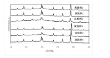
実施例1~4、比較例1~2で得られた硫化物系固体電解質のX線回折測定の結果を図3に示す。
図3に示したとおり、実施例1~4、比較例1~2では、少なくとも、2θ=19.90°±0.50°、20.20°±0.50°、26.70°±0.50°、及び29.20°±0.50°に回折ピークが観測され、このパターンはICSDデータベースのLi10GeP2S12と一致し、LGPS型の結晶構造を持つことが確認できた。
また、比較例1では不純物ピークが多く確認された。これらは、原料のSnS2が溶媒への溶解性に乏しいため、合成時にSnが固体電解質中に均一に分散しなかったことにより確認された不純物であると考えられる。
実施例1~4および比較例1~2で得られた硫化物系固体電解質を一軸成型(420MPa)に供し、厚さ約1mm、直径10mmのディスクを得た。全固体電池評価セル(宝泉株式会社製)を用い、室温(25℃)において、四端子法による交流インピーダンス測定(Solartron社製「SI1260 IMPEDANCE/GAIN―PHASE ANALYZER」)を行い、リチウムイオン伝導度を算出した。
具体的には、サンプルを25℃に設定した恒温槽に入れて30分間保持した後にリチウムイオン伝導度を測定した。測定周波数範囲は0.1Hz~1MHz、振幅は50mVとした。リチウムイオン伝導度の測定結果を下記表1に示す。

2 固体電解質層
3 負極層
10 全固体電池
Claims (13)
- 有機溶媒中に少なくともリチウム(Li)元素、スズ(Sn)元素、リン(P)元素、及び硫黄(S)元素を含む均一溶液を調製する溶液化工程と、
前記均一溶液から前記有機溶媒を除去して前駆体を得る乾燥工程と、
前記前駆体を加熱処理して硫化物系固体電解質を得る加熱処理工程と、を含むことを特徴とする硫化物系固体電解質の製造方法。 - 前記溶液化工程が、Li2SとP2S5とを前記有機溶媒中で混合することによってLi-P-S均一溶液を調製する溶液化工程1と、前記有機溶媒中に少なくともリチウム(Li)元素、スズ(Sn)元素、及び硫黄(S)元素を含むLi-Sn-S均一溶液を調製する溶液化工程2とを含み、
前記Li-P-S均一溶液、及び前記Li-Sn-S均一溶液を混合して均一溶液を調製することを含む、請求項1に記載の硫化物系固体電解質の製造方法。 - 前記溶液化工程が、Li2SとP2S5とを前記有機溶媒中で混合することによってLi-P-S均一溶液を調製する溶液化工程1と、前記有機溶媒中に少なくともリチウム(Li)元素、スズ(Sn)元素、及び硫黄(S)元素を含むLi-Sn-S均一溶液を調製する溶液化工程2と、Li2SとSとを前記有機溶媒中で混合することによってLi-S均一溶液を調製する溶液化工程3とを含み、
前記Li-P-S均一溶液、前記Li-Sn-S均一溶液、及び前記Li-S均一溶液を混合して均一溶液を調製することを含む、請求項1に記載の硫化物系固体電解質の製造方法。 - 前記溶液化工程が、Li2SとP2S5とを前記有機溶媒中で混合することによってLi-P-S均一溶液を調製する溶液化工程1と、前記有機溶媒中に少なくともリチウム(Li)元素、スズ(Sn)元素、及び硫黄(S)元素を含むLi-Sn-S均一溶液を調製する溶液化工程2と、Li2SとSとを前記有機溶媒中で混合することによってLi-S均一溶液を調製する溶液化工程3と、前記有機溶媒中に少なくともリチウム(Li)元素、ケイ素(Si)元素、及び硫黄(S)元素を含むLi-Si-S均一溶液を調製する溶液化工程4とを含み、
前記Li-P-S均一溶液、前記Li-Sn-S均一溶液、前記Li-S均一溶液、及び前記Li-Si-S均一溶液を混合して均一溶液を調製することを含む、請求項1に記載の硫化物系固体電解質の製造方法。 - 前記溶液化工程2が、Li2S、SnS、及びSを前記有機溶媒中で混合することによって、Li-Sn-S均一溶液を調製することを含む、請求項2から4のいずれかに記載の硫化物系固体電解質の製造方法。
- 前記溶液化工程4が、Li2S、SiS2、及びSを前記有機溶媒中で混合することによって、Li-Si-S均一溶液を調製することを含む、請求項4に記載の硫化物系固体電解質の製造方法。
- Li3PS4含有スラリー液を調製するスラリー化工程1と、
有機溶媒中に少なくともリチウム(Li)元素、スズ(Sn)元素、及び硫黄(S)元素を含むLi-Sn-S均一溶液を調製する溶液化工程と、
前記Li3PS4含有スラリー液、及び前記Li-Sn-S均一溶液を混合し、混合スラリー液を調製するスラリー化工程2と、
前記混合スラリー液から前記有機溶媒を除去して前駆体を得る乾燥工程と、
前記前駆体を加熱処理して硫化物系固体電解質を得る加熱処理工程と、を含むことを特徴とする硫化物系固体電解質の製造方法。 - 前記溶液化工程が、前記有機溶媒中にLi2S、SnS、及びSを添加して混合し、Li-Sn-S均一溶液を調製することを含む、請求項7に記載の硫化物系固体電解質の製造方法。
- 前記有機溶媒が、エーテル系溶媒、ニトリル系溶媒、及びエステル系溶媒からなる群より選ばれる少なくとも1種である、請求項1から8のいずれかに記載の硫化物系固体電解質の製造方法。
- 前記有機溶媒が、テトラヒドロフラン、アセトニトリル、酢酸エチル、及び酢酸メチルからなる群より選ばれる少なくとも1種である、請求項1から9のいずれかに記載の硫化物系固体電解質の製造方法。
- 前記乾燥工程における温度が、60~280℃である、請求項1から10のいずれかに記載の硫化物系固体電解質の製造方法。
- 前記加熱処理工程における温度が、200℃~700℃である、請求項1から11のいずれかに記載の硫化物系固体電解質の製造方法。
- 前記硫化物系固体電解質が、LGPS系固体電解質を含有し、X線回折(CuKα:λ=1.5405Å)において、少なくとも、2θ=19.90°±0.50°、20.20°±0.50°、26.70°±0.50°、及び29.20°±0.50°の位置にピークを有する、請求項1から12のいずれかに記載の硫化物系固体電解質の製造方法。
Priority Applications (9)
| Application Number | Priority Date | Filing Date | Title |
|---|---|---|---|
| KR1020227015944A KR102927946B1 (ko) | 2020-01-17 | 2021-01-06 | Sn을 포함하는 황화물계 고체 전해질의 제조 방법 |
| AU2021206935A AU2021206935A1 (en) | 2020-01-17 | 2021-01-06 | Method for producing sulfide solid electrolyte including Sn |
| JP2021571154A JP7658281B2 (ja) | 2020-01-17 | 2021-01-06 | Snを含む硫化物系固体電解質の製造方法 |
| BR112022012247A BR112022012247A2 (pt) | 2020-01-17 | 2021-01-06 | Método para produzir um eletrólito sólido à base de sulfeto |
| CN202180009137.1A CN115023773B (zh) | 2020-01-17 | 2021-01-06 | 含Sn的硫化物系固体电解质的制造方法 |
| CA3167101A CA3167101A1 (en) | 2020-01-17 | 2021-01-06 | Method for producing sulfide solid electrolyte including sn |
| EP21741412.7A EP4092691B1 (en) | 2020-01-17 | 2021-01-06 | Method for producing sulfide solid electrolyte including sn |
| US17/792,524 US12525640B2 (en) | 2020-01-17 | 2021-01-06 | Method for producing sulfide solid electrolyte including Sn |
| US19/422,854 US20260121112A1 (en) | 2020-01-17 | 2025-12-17 | METHOD FOR PRODUCING SULFIDE SOLID ELECTROLYTE INCLUDING Sn |
Applications Claiming Priority (2)
| Application Number | Priority Date | Filing Date | Title |
|---|---|---|---|
| JP2020-005850 | 2020-01-17 | ||
| JP2020005850 | 2020-01-17 |
Related Child Applications (2)
| Application Number | Title | Priority Date | Filing Date |
|---|---|---|---|
| US17/792,524 A-371-Of-International US12525640B2 (en) | 2020-01-17 | 2021-01-06 | Method for producing sulfide solid electrolyte including Sn |
| US19/422,854 Division US20260121112A1 (en) | 2020-01-17 | 2025-12-17 | METHOD FOR PRODUCING SULFIDE SOLID ELECTROLYTE INCLUDING Sn |
Publications (1)
| Publication Number | Publication Date |
|---|---|
| WO2021145248A1 true WO2021145248A1 (ja) | 2021-07-22 |
Family
ID=76863976
Family Applications (1)
| Application Number | Title | Priority Date | Filing Date |
|---|---|---|---|
| PCT/JP2021/000182 Ceased WO2021145248A1 (ja) | 2020-01-17 | 2021-01-06 | Snを含む硫化物系固体電解質の製造方法 |
Country Status (10)
| Country | Link |
|---|---|
| US (2) | US12525640B2 (ja) |
| EP (1) | EP4092691B1 (ja) |
| JP (1) | JP7658281B2 (ja) |
| KR (1) | KR102927946B1 (ja) |
| CN (1) | CN115023773B (ja) |
| AU (1) | AU2021206935A1 (ja) |
| BR (1) | BR112022012247A2 (ja) |
| CA (1) | CA3167101A1 (ja) |
| TW (1) | TWI879866B (ja) |
| WO (1) | WO2021145248A1 (ja) |
Cited By (2)
| Publication number | Priority date | Publication date | Assignee | Title |
|---|---|---|---|---|
| CN110867606A (zh) * | 2019-10-18 | 2020-03-06 | 长三角物理研究中心有限公司 | 一种硫化物固态电解质的制备方法 |
| JP2023076114A (ja) * | 2021-11-22 | 2023-06-01 | トヨタ自動車株式会社 | 硫化物固体電解質、電池および硫化物固体電解質の製造方法 |
Families Citing this family (4)
| Publication number | Priority date | Publication date | Assignee | Title |
|---|---|---|---|---|
| JPWO2023204163A1 (ja) * | 2022-04-21 | 2023-10-26 | ||
| KR20250061289A (ko) * | 2023-10-27 | 2025-05-08 | 포스코홀딩스 주식회사 | 고체 전해질, 이의 제조방법 및 이를 포함하는 전고체 전지 |
| CN119913600B (zh) * | 2025-02-08 | 2025-11-04 | 曲阜师范大学 | 高质量、大尺寸体相三磷化锡单晶的制备方法 |
| CN121642127A (zh) * | 2026-02-03 | 2026-03-10 | 瑞固(衢州)新材料科技有限公司 | 一种固体电解质的制备方法 |
Citations (5)
| Publication number | Priority date | Publication date | Assignee | Title |
|---|---|---|---|---|
| WO2017002971A1 (ja) * | 2015-07-02 | 2017-01-05 | 国立大学法人東京工業大学 | 硫化物固体電解質材料、電池および硫化物固体電解質材料の製造方法 |
| WO2017155119A1 (ja) * | 2016-03-11 | 2017-09-14 | 国立大学法人東京工業大学 | 硫化物固体電解質 |
| WO2019044517A1 (ja) * | 2017-09-01 | 2019-03-07 | 三菱瓦斯化学株式会社 | Lgps系固体電解質の製造方法 |
| JP2019169459A (ja) | 2017-09-06 | 2019-10-03 | 出光興産株式会社 | 固体電解質の製造方法 |
| WO2019239949A1 (ja) * | 2018-06-13 | 2019-12-19 | 三菱瓦斯化学株式会社 | Lgps系固体電解質および製造方法 |
Family Cites Families (5)
| Publication number | Priority date | Publication date | Assignee | Title |
|---|---|---|---|---|
| JP5544686B2 (ja) | 2008-03-28 | 2014-07-09 | 住友化学株式会社 | 射出成形同時貼合用多層フィルム |
| WO2013118722A1 (ja) * | 2012-02-06 | 2013-08-15 | トヨタ自動車株式会社 | 硫化物固体電解質材料、電池および硫化物固体電解質材料の製造方法 |
| CN105098228A (zh) | 2014-05-05 | 2015-11-25 | 中国科学院宁波材料技术与工程研究所 | 硫化物固体电解质材料及其制备方法 |
| JP6996553B2 (ja) * | 2017-03-22 | 2022-02-04 | 三菱瓦斯化学株式会社 | Lgps系固体電解質の製造方法 |
| CN108695553B (zh) | 2018-07-11 | 2020-10-09 | 中国科学院宁波材料技术与工程研究所 | 一种全固态钠二次电池电解质、其制备方法及其应用 |
-
2021
- 2021-01-06 JP JP2021571154A patent/JP7658281B2/ja active Active
- 2021-01-06 EP EP21741412.7A patent/EP4092691B1/en active Active
- 2021-01-06 AU AU2021206935A patent/AU2021206935A1/en active Pending
- 2021-01-06 KR KR1020227015944A patent/KR102927946B1/ko active Active
- 2021-01-06 US US17/792,524 patent/US12525640B2/en active Active
- 2021-01-06 WO PCT/JP2021/000182 patent/WO2021145248A1/ja not_active Ceased
- 2021-01-06 CN CN202180009137.1A patent/CN115023773B/zh active Active
- 2021-01-06 CA CA3167101A patent/CA3167101A1/en active Pending
- 2021-01-06 BR BR112022012247A patent/BR112022012247A2/pt unknown
- 2021-01-12 TW TW110101026A patent/TWI879866B/zh active
-
2025
- 2025-12-17 US US19/422,854 patent/US20260121112A1/en active Pending
Patent Citations (5)
| Publication number | Priority date | Publication date | Assignee | Title |
|---|---|---|---|---|
| WO2017002971A1 (ja) * | 2015-07-02 | 2017-01-05 | 国立大学法人東京工業大学 | 硫化物固体電解質材料、電池および硫化物固体電解質材料の製造方法 |
| WO2017155119A1 (ja) * | 2016-03-11 | 2017-09-14 | 国立大学法人東京工業大学 | 硫化物固体電解質 |
| WO2019044517A1 (ja) * | 2017-09-01 | 2019-03-07 | 三菱瓦斯化学株式会社 | Lgps系固体電解質の製造方法 |
| JP2019169459A (ja) | 2017-09-06 | 2019-10-03 | 出光興産株式会社 | 固体電解質の製造方法 |
| WO2019239949A1 (ja) * | 2018-06-13 | 2019-12-19 | 三菱瓦斯化学株式会社 | Lgps系固体電解質および製造方法 |
Non-Patent Citations (2)
| Title |
|---|
| J. AM. CHEM. SOC., vol. 135, 2013, pages 15694 - 15697 |
| See also references of EP4092691A4 |
Cited By (3)
| Publication number | Priority date | Publication date | Assignee | Title |
|---|---|---|---|---|
| CN110867606A (zh) * | 2019-10-18 | 2020-03-06 | 长三角物理研究中心有限公司 | 一种硫化物固态电解质的制备方法 |
| JP2023076114A (ja) * | 2021-11-22 | 2023-06-01 | トヨタ自動車株式会社 | 硫化物固体電解質、電池および硫化物固体電解質の製造方法 |
| JP7476867B2 (ja) | 2021-11-22 | 2024-05-01 | トヨタ自動車株式会社 | 硫化物固体電解質、電池および硫化物固体電解質の製造方法 |
Also Published As
| Publication number | Publication date |
|---|---|
| US12525640B2 (en) | 2026-01-13 |
| US20230071336A1 (en) | 2023-03-09 |
| AU2021206935A1 (en) | 2022-07-28 |
| CN115023773A (zh) | 2022-09-06 |
| EP4092691B1 (en) | 2025-04-23 |
| US20260121112A1 (en) | 2026-04-30 |
| EP4092691A1 (en) | 2022-11-23 |
| KR102927946B1 (ko) | 2026-02-13 |
| TWI879866B (zh) | 2025-04-11 |
| KR20220127807A (ko) | 2022-09-20 |
| EP4092691C0 (en) | 2025-04-23 |
| CN115023773B (zh) | 2025-05-27 |
| BR112022012247A2 (pt) | 2022-08-30 |
| EP4092691A4 (en) | 2023-12-06 |
| JP7658281B2 (ja) | 2025-04-08 |
| JPWO2021145248A1 (ja) | 2021-07-22 |
| CA3167101A1 (en) | 2021-07-22 |
| TW202132216A (zh) | 2021-09-01 |
Similar Documents
| Publication | Publication Date | Title |
|---|---|---|
| US11799128B2 (en) | LGPS-based solid electrolyte and production method | |
| JP7308147B2 (ja) | Lgps系固体電解質の製造方法 | |
| JP7658281B2 (ja) | Snを含む硫化物系固体電解質の製造方法 | |
| JP6996553B2 (ja) | Lgps系固体電解質の製造方法 | |
| JP6984652B2 (ja) | Li3PS4を有する固体電解質の製造方法 | |
| JP7513014B2 (ja) | 硫化物系固体電解質の製造方法 | |
| JP7400491B2 (ja) | Lgps系固体電解質の製造方法 | |
| RU2822115C1 (ru) | СПОСОБ ПОЛУЧЕНИЯ СУЛЬФИДНОГО ТВЕРДОГО ЭЛЕКТРОЛИТА, СОДЕРЖАЩЕГО Sn | |
| RU2804507C2 (ru) | Способ получения сульфидного твердого электролита | |
| AU2026202760A1 (en) | Method for producing sulfide solid electrolyte including Sn |
Legal Events
| Date | Code | Title | Description |
|---|---|---|---|
| 121 | Ep: the epo has been informed by wipo that ep was designated in this application |
Ref document number: 21741412 Country of ref document: EP Kind code of ref document: A1 |
|
| ENP | Entry into the national phase |
Ref document number: 2021571154 Country of ref document: JP Kind code of ref document: A |
|
| REG | Reference to national code |
Ref country code: BR Ref legal event code: B01A Ref document number: 112022012247 Country of ref document: BR |
|
| ENP | Entry into the national phase |
Ref document number: 3167101 Country of ref document: CA |
|
| ENP | Entry into the national phase |
Ref document number: 2021206935 Country of ref document: AU Date of ref document: 20210106 Kind code of ref document: A |
|
| NENP | Non-entry into the national phase |
Ref country code: DE |
|
| ENP | Entry into the national phase |
Ref document number: 2021741412 Country of ref document: EP Effective date: 20220817 |
|
| ENP | Entry into the national phase |
Ref document number: 112022012247 Country of ref document: BR Kind code of ref document: A2 Effective date: 20220620 |
|
| WWG | Wipo information: grant in national office |
Ref document number: 2021741412 Country of ref document: EP |
|
| WWG | Wipo information: grant in national office |
Ref document number: 202180009137.1 Country of ref document: CN |
|
| WWG | Wipo information: grant in national office |
Ref document number: 17792524 Country of ref document: US |