WO2021145301A1 - 電動車両の制御装置、電動車両の制御方法および電動車両の制御システム - Google Patents
電動車両の制御装置、電動車両の制御方法および電動車両の制御システム Download PDFInfo
- Publication number
- WO2021145301A1 WO2021145301A1 PCT/JP2021/000628 JP2021000628W WO2021145301A1 WO 2021145301 A1 WO2021145301 A1 WO 2021145301A1 JP 2021000628 W JP2021000628 W JP 2021000628W WO 2021145301 A1 WO2021145301 A1 WO 2021145301A1
- Authority
- WO
- WIPO (PCT)
- Prior art keywords
- vehicle
- amount
- accelerator pedal
- regenerative braking
- braking force
- Prior art date
- Legal status (The legal status is an assumption and is not a legal conclusion. Google has not performed a legal analysis and makes no representation as to the accuracy of the status listed.)
- Ceased
Links
Images


Classifications
-
- B—PERFORMING OPERATIONS; TRANSPORTING
- B60—VEHICLES IN GENERAL
- B60L—PROPULSION OF ELECTRICALLY-PROPELLED VEHICLES; SUPPLYING ELECTRIC POWER FOR AUXILIARY EQUIPMENT OF ELECTRICALLY-PROPELLED VEHICLES; ELECTRODYNAMIC BRAKE SYSTEMS FOR VEHICLES IN GENERAL; MAGNETIC SUSPENSION OR LEVITATION FOR VEHICLES; MONITORING OPERATING VARIABLES OF ELECTRICALLY-PROPELLED VEHICLES; ELECTRIC SAFETY DEVICES FOR ELECTRICALLY-PROPELLED VEHICLES
- B60L7/00—Electrodynamic brake systems for vehicles in general
- B60L7/10—Dynamic electric regenerative braking
- B60L7/18—Controlling the braking effect
-
- B—PERFORMING OPERATIONS; TRANSPORTING
- B60—VEHICLES IN GENERAL
- B60L—PROPULSION OF ELECTRICALLY-PROPELLED VEHICLES; SUPPLYING ELECTRIC POWER FOR AUXILIARY EQUIPMENT OF ELECTRICALLY-PROPELLED VEHICLES; ELECTRODYNAMIC BRAKE SYSTEMS FOR VEHICLES IN GENERAL; MAGNETIC SUSPENSION OR LEVITATION FOR VEHICLES; MONITORING OPERATING VARIABLES OF ELECTRICALLY-PROPELLED VEHICLES; ELECTRIC SAFETY DEVICES FOR ELECTRICALLY-PROPELLED VEHICLES
- B60L15/00—Methods, circuits, or devices for controlling the traction-motor speed of electrically-propelled vehicles
- B60L15/20—Methods, circuits, or devices for controlling the traction-motor speed of electrically-propelled vehicles for control of the vehicle or its driving motor to achieve a desired performance, e.g. speed, torque, programmed variation of speed
- B60L15/2009—Methods, circuits, or devices for controlling the traction-motor speed of electrically-propelled vehicles for control of the vehicle or its driving motor to achieve a desired performance, e.g. speed, torque, programmed variation of speed for braking
-
- B—PERFORMING OPERATIONS; TRANSPORTING
- B60—VEHICLES IN GENERAL
- B60L—PROPULSION OF ELECTRICALLY-PROPELLED VEHICLES; SUPPLYING ELECTRIC POWER FOR AUXILIARY EQUIPMENT OF ELECTRICALLY-PROPELLED VEHICLES; ELECTRODYNAMIC BRAKE SYSTEMS FOR VEHICLES IN GENERAL; MAGNETIC SUSPENSION OR LEVITATION FOR VEHICLES; MONITORING OPERATING VARIABLES OF ELECTRICALLY-PROPELLED VEHICLES; ELECTRIC SAFETY DEVICES FOR ELECTRICALLY-PROPELLED VEHICLES
- B60L15/00—Methods, circuits, or devices for controlling the traction-motor speed of electrically-propelled vehicles
- B60L15/20—Methods, circuits, or devices for controlling the traction-motor speed of electrically-propelled vehicles for control of the vehicle or its driving motor to achieve a desired performance, e.g. speed, torque, programmed variation of speed
- B60L15/2036—Electric differentials, e.g. for supporting steering vehicles
-
- B—PERFORMING OPERATIONS; TRANSPORTING
- B60—VEHICLES IN GENERAL
- B60L—PROPULSION OF ELECTRICALLY-PROPELLED VEHICLES; SUPPLYING ELECTRIC POWER FOR AUXILIARY EQUIPMENT OF ELECTRICALLY-PROPELLED VEHICLES; ELECTRODYNAMIC BRAKE SYSTEMS FOR VEHICLES IN GENERAL; MAGNETIC SUSPENSION OR LEVITATION FOR VEHICLES; MONITORING OPERATING VARIABLES OF ELECTRICALLY-PROPELLED VEHICLES; ELECTRIC SAFETY DEVICES FOR ELECTRICALLY-PROPELLED VEHICLES
- B60L7/00—Electrodynamic brake systems for vehicles in general
- B60L7/24—Electrodynamic brake systems for vehicles in general with additional mechanical or electromagnetic braking
- B60L7/26—Controlling the braking effect
-
- B—PERFORMING OPERATIONS; TRANSPORTING
- B60—VEHICLES IN GENERAL
- B60W—CONJOINT CONTROL OF VEHICLE SUB-UNITS OF DIFFERENT TYPE OR DIFFERENT FUNCTION; CONTROL SYSTEMS SPECIALLY ADAPTED FOR HYBRID VEHICLES; ROAD VEHICLE DRIVE CONTROL SYSTEMS FOR PURPOSES NOT RELATED TO THE CONTROL OF A PARTICULAR SUB-UNIT
- B60W10/00—Conjoint control of vehicle sub-units of different type or different function
- B60W10/04—Conjoint control of vehicle sub-units of different type or different function including control of propulsion units
- B60W10/08—Conjoint control of vehicle sub-units of different type or different function including control of propulsion units including control of electric propulsion units, e.g. motors or generators
-
- B—PERFORMING OPERATIONS; TRANSPORTING
- B60—VEHICLES IN GENERAL
- B60W—CONJOINT CONTROL OF VEHICLE SUB-UNITS OF DIFFERENT TYPE OR DIFFERENT FUNCTION; CONTROL SYSTEMS SPECIALLY ADAPTED FOR HYBRID VEHICLES; ROAD VEHICLE DRIVE CONTROL SYSTEMS FOR PURPOSES NOT RELATED TO THE CONTROL OF A PARTICULAR SUB-UNIT
- B60W30/00—Purposes of road vehicle drive control systems not related to the control of a particular sub-unit, e.g. of systems using conjoint control of vehicle sub-units
- B60W30/02—Control of vehicle driving stability
- B60W30/045—Improving turning performance
-
- B—PERFORMING OPERATIONS; TRANSPORTING
- B60—VEHICLES IN GENERAL
- B60W—CONJOINT CONTROL OF VEHICLE SUB-UNITS OF DIFFERENT TYPE OR DIFFERENT FUNCTION; CONTROL SYSTEMS SPECIALLY ADAPTED FOR HYBRID VEHICLES; ROAD VEHICLE DRIVE CONTROL SYSTEMS FOR PURPOSES NOT RELATED TO THE CONTROL OF A PARTICULAR SUB-UNIT
- B60W30/00—Purposes of road vehicle drive control systems not related to the control of a particular sub-unit, e.g. of systems using conjoint control of vehicle sub-units
- B60W30/18—Propelling the vehicle
- B60W30/18009—Propelling the vehicle related to particular drive situations
- B60W30/18109—Braking
- B60W30/18127—Regenerative braking
-
- B—PERFORMING OPERATIONS; TRANSPORTING
- B60—VEHICLES IN GENERAL
- B60L—PROPULSION OF ELECTRICALLY-PROPELLED VEHICLES; SUPPLYING ELECTRIC POWER FOR AUXILIARY EQUIPMENT OF ELECTRICALLY-PROPELLED VEHICLES; ELECTRODYNAMIC BRAKE SYSTEMS FOR VEHICLES IN GENERAL; MAGNETIC SUSPENSION OR LEVITATION FOR VEHICLES; MONITORING OPERATING VARIABLES OF ELECTRICALLY-PROPELLED VEHICLES; ELECTRIC SAFETY DEVICES FOR ELECTRICALLY-PROPELLED VEHICLES
- B60L2220/00—Electrical machine types; Structures or applications thereof
- B60L2220/40—Electrical machine applications
- B60L2220/42—Electrical machine applications with use of more than one motor
-
- B—PERFORMING OPERATIONS; TRANSPORTING
- B60—VEHICLES IN GENERAL
- B60L—PROPULSION OF ELECTRICALLY-PROPELLED VEHICLES; SUPPLYING ELECTRIC POWER FOR AUXILIARY EQUIPMENT OF ELECTRICALLY-PROPELLED VEHICLES; ELECTRODYNAMIC BRAKE SYSTEMS FOR VEHICLES IN GENERAL; MAGNETIC SUSPENSION OR LEVITATION FOR VEHICLES; MONITORING OPERATING VARIABLES OF ELECTRICALLY-PROPELLED VEHICLES; ELECTRIC SAFETY DEVICES FOR ELECTRICALLY-PROPELLED VEHICLES
- B60L2240/00—Control parameters of input or output; Target parameters
- B60L2240/10—Vehicle control parameters
- B60L2240/12—Speed
-
- B—PERFORMING OPERATIONS; TRANSPORTING
- B60—VEHICLES IN GENERAL
- B60L—PROPULSION OF ELECTRICALLY-PROPELLED VEHICLES; SUPPLYING ELECTRIC POWER FOR AUXILIARY EQUIPMENT OF ELECTRICALLY-PROPELLED VEHICLES; ELECTRODYNAMIC BRAKE SYSTEMS FOR VEHICLES IN GENERAL; MAGNETIC SUSPENSION OR LEVITATION FOR VEHICLES; MONITORING OPERATING VARIABLES OF ELECTRICALLY-PROPELLED VEHICLES; ELECTRIC SAFETY DEVICES FOR ELECTRICALLY-PROPELLED VEHICLES
- B60L2240/00—Control parameters of input or output; Target parameters
- B60L2240/10—Vehicle control parameters
- B60L2240/24—Steering angle
-
- B—PERFORMING OPERATIONS; TRANSPORTING
- B60—VEHICLES IN GENERAL
- B60L—PROPULSION OF ELECTRICALLY-PROPELLED VEHICLES; SUPPLYING ELECTRIC POWER FOR AUXILIARY EQUIPMENT OF ELECTRICALLY-PROPELLED VEHICLES; ELECTRODYNAMIC BRAKE SYSTEMS FOR VEHICLES IN GENERAL; MAGNETIC SUSPENSION OR LEVITATION FOR VEHICLES; MONITORING OPERATING VARIABLES OF ELECTRICALLY-PROPELLED VEHICLES; ELECTRIC SAFETY DEVICES FOR ELECTRICALLY-PROPELLED VEHICLES
- B60L2240/00—Control parameters of input or output; Target parameters
- B60L2240/40—Drive Train control parameters
- B60L2240/42—Drive Train control parameters related to electric machines
- B60L2240/423—Torque
-
- B—PERFORMING OPERATIONS; TRANSPORTING
- B60—VEHICLES IN GENERAL
- B60L—PROPULSION OF ELECTRICALLY-PROPELLED VEHICLES; SUPPLYING ELECTRIC POWER FOR AUXILIARY EQUIPMENT OF ELECTRICALLY-PROPELLED VEHICLES; ELECTRODYNAMIC BRAKE SYSTEMS FOR VEHICLES IN GENERAL; MAGNETIC SUSPENSION OR LEVITATION FOR VEHICLES; MONITORING OPERATING VARIABLES OF ELECTRICALLY-PROPELLED VEHICLES; ELECTRIC SAFETY DEVICES FOR ELECTRICALLY-PROPELLED VEHICLES
- B60L2240/00—Control parameters of input or output; Target parameters
- B60L2240/40—Drive Train control parameters
- B60L2240/46—Drive Train control parameters related to wheels
- B60L2240/461—Speed
-
- B—PERFORMING OPERATIONS; TRANSPORTING
- B60—VEHICLES IN GENERAL
- B60L—PROPULSION OF ELECTRICALLY-PROPELLED VEHICLES; SUPPLYING ELECTRIC POWER FOR AUXILIARY EQUIPMENT OF ELECTRICALLY-PROPELLED VEHICLES; ELECTRODYNAMIC BRAKE SYSTEMS FOR VEHICLES IN GENERAL; MAGNETIC SUSPENSION OR LEVITATION FOR VEHICLES; MONITORING OPERATING VARIABLES OF ELECTRICALLY-PROPELLED VEHICLES; ELECTRIC SAFETY DEVICES FOR ELECTRICALLY-PROPELLED VEHICLES
- B60L2250/00—Driver interactions
- B60L2250/26—Driver interactions by pedal actuation
-
- B—PERFORMING OPERATIONS; TRANSPORTING
- B60—VEHICLES IN GENERAL
- B60W—CONJOINT CONTROL OF VEHICLE SUB-UNITS OF DIFFERENT TYPE OR DIFFERENT FUNCTION; CONTROL SYSTEMS SPECIALLY ADAPTED FOR HYBRID VEHICLES; ROAD VEHICLE DRIVE CONTROL SYSTEMS FOR PURPOSES NOT RELATED TO THE CONTROL OF A PARTICULAR SUB-UNIT
- B60W50/00—Details of control systems for road vehicle drive control not related to the control of a particular sub-unit, e.g. process diagnostic or vehicle driver interfaces
- B60W2050/0001—Details of the control system
- B60W2050/0019—Control system elements or transfer functions
- B60W2050/0022—Gains, weighting coefficients or weighting functions
- B60W2050/0024—Variable gains
-
- B—PERFORMING OPERATIONS; TRANSPORTING
- B60—VEHICLES IN GENERAL
- B60W—CONJOINT CONTROL OF VEHICLE SUB-UNITS OF DIFFERENT TYPE OR DIFFERENT FUNCTION; CONTROL SYSTEMS SPECIALLY ADAPTED FOR HYBRID VEHICLES; ROAD VEHICLE DRIVE CONTROL SYSTEMS FOR PURPOSES NOT RELATED TO THE CONTROL OF A PARTICULAR SUB-UNIT
- B60W2520/00—Input parameters relating to overall vehicle dynamics
- B60W2520/10—Longitudinal speed
-
- B—PERFORMING OPERATIONS; TRANSPORTING
- B60—VEHICLES IN GENERAL
- B60W—CONJOINT CONTROL OF VEHICLE SUB-UNITS OF DIFFERENT TYPE OR DIFFERENT FUNCTION; CONTROL SYSTEMS SPECIALLY ADAPTED FOR HYBRID VEHICLES; ROAD VEHICLE DRIVE CONTROL SYSTEMS FOR PURPOSES NOT RELATED TO THE CONTROL OF A PARTICULAR SUB-UNIT
- B60W2540/00—Input parameters relating to occupants
- B60W2540/10—Accelerator pedal position
-
- B—PERFORMING OPERATIONS; TRANSPORTING
- B60—VEHICLES IN GENERAL
- B60W—CONJOINT CONTROL OF VEHICLE SUB-UNITS OF DIFFERENT TYPE OR DIFFERENT FUNCTION; CONTROL SYSTEMS SPECIALLY ADAPTED FOR HYBRID VEHICLES; ROAD VEHICLE DRIVE CONTROL SYSTEMS FOR PURPOSES NOT RELATED TO THE CONTROL OF A PARTICULAR SUB-UNIT
- B60W2540/00—Input parameters relating to occupants
- B60W2540/18—Steering angle
-
- B—PERFORMING OPERATIONS; TRANSPORTING
- B60—VEHICLES IN GENERAL
- B60W—CONJOINT CONTROL OF VEHICLE SUB-UNITS OF DIFFERENT TYPE OR DIFFERENT FUNCTION; CONTROL SYSTEMS SPECIALLY ADAPTED FOR HYBRID VEHICLES; ROAD VEHICLE DRIVE CONTROL SYSTEMS FOR PURPOSES NOT RELATED TO THE CONTROL OF A PARTICULAR SUB-UNIT
- B60W2710/00—Output or target parameters relating to a particular sub-units
- B60W2710/08—Electric propulsion units
- B60W2710/083—Torque
- B60W2710/085—Torque change rate
-
- B—PERFORMING OPERATIONS; TRANSPORTING
- B60—VEHICLES IN GENERAL
- B60W—CONJOINT CONTROL OF VEHICLE SUB-UNITS OF DIFFERENT TYPE OR DIFFERENT FUNCTION; CONTROL SYSTEMS SPECIALLY ADAPTED FOR HYBRID VEHICLES; ROAD VEHICLE DRIVE CONTROL SYSTEMS FOR PURPOSES NOT RELATED TO THE CONTROL OF A PARTICULAR SUB-UNIT
- B60W2720/00—Output or target parameters relating to overall vehicle dynamics
- B60W2720/26—Wheel slip
-
- Y—GENERAL TAGGING OF NEW TECHNOLOGICAL DEVELOPMENTS; GENERAL TAGGING OF CROSS-SECTIONAL TECHNOLOGIES SPANNING OVER SEVERAL SECTIONS OF THE IPC; TECHNICAL SUBJECTS COVERED BY FORMER USPC CROSS-REFERENCE ART COLLECTIONS [XRACs] AND DIGESTS
- Y02—TECHNOLOGIES OR APPLICATIONS FOR MITIGATION OR ADAPTATION AGAINST CLIMATE CHANGE
- Y02T—CLIMATE CHANGE MITIGATION TECHNOLOGIES RELATED TO TRANSPORTATION
- Y02T10/00—Road transport of goods or passengers
- Y02T10/60—Other road transportation technologies with climate change mitigation effect
- Y02T10/72—Electric energy management in electromobility
Definitions
- the present invention relates to an electric vehicle control device, an electric vehicle control method, and an electric vehicle control system.
- Patent Document 1 discloses that the lower the vehicle body speed, the more the predetermined position is set to shift to the non-operating side of the accelerator pedal.
- Patent Document 1 the stroke amount of the accelerator pedal, which switches between the driving force and the braking force, is merely changed according to the vehicle body speed, and the operability by the driver when the vehicle turns is not considered at all. do not have.
- One of the objects of the present invention is an electric vehicle control device, an electric vehicle control method, and an electric vehicle that can improve operability when regenerative braking is performed by depressing the accelerator pedal when the vehicle is turning. It is to provide a control system.
- the control device, control method, and control system of the electric vehicle regenerates the operation amount of the accelerator pedal based on the operation information regarding the depressing of the accelerator pedal of the vehicle and the turning information regarding the turning of the vehicle. It was decided to obtain change rate information regarding the amount of change in braking force over time and output a regenerative braking control command for applying regenerative braking force to the wheels based on the change rate information.
- FIG. It is a block diagram of the control system of the electric vehicle in Embodiment 1.
- FIG. It is a control block diagram which shows the drive torque calculation process of the vehicle control device in Embodiment 1.
- FIG. It is a flowchart which shows the base torque change amount limiting process at the time of the driver required torque calculation in Embodiment 1.
- FIG. It is a figure which shows the gain map C used in the vehicle control device in Embodiment 1.
- FIG. It is a figure which shows the torque map B used in the vehicle control device in Embodiment 1.
- FIG. It is a figure which shows the turning state when the driver operates the accelerator pedal to the foot release side on the road surface which has a certain road surface gradient (no road surface gradient), and turns during deceleration running by one-pedal control.
- FIG. 1 is a configuration diagram of a control system for an electric vehicle according to the first embodiment.
- the electric vehicle 1 has a front motor (front wheel electric motor) 3 that outputs torque to the front wheels 2FL and 2FR. Power transmission between the front motor 3 and the front wheels 2FL and 2FR is performed via the reduction gear 4, the differential 5, and the front axles 6FL and 6FR.
- the electric vehicle 1 has a rear motor (rear wheel electric motor) 7 that outputs torque to the rear wheels 2RL and 2RR.
- the front wheels 2FL, 2FR and the rear wheels 2RL, 2RR are also collectively referred to as drive wheels 2. Power transmission between the rear motor 7 and the rear wheels 2RL and 2RR is performed via the reduction gear 8, the dog clutch 9, the differential 10, and the rear axles 6RL and 6RR.
- the dog clutch 9 When the dog clutch 9 is engaged, power is transmitted between the rear motor 7 and the rear wheels 2RL and 2RR. On the other hand, when the dog clutch 9 is released, power is not transmitted between the rear motor 7 and the rear wheels 2RL and 2RR.
- Each wheel 2FL, 2FR, 2RL, 2RR has wheel speed sensors 11FL, 11FR, 11RL, 11RR for detecting the wheel speed.
- the front motor 3 has a front wheel resolver 12 that detects the motor rotation speed.
- the rear motor 7 has a rear wheel resolver 13 that detects the motor rotation speed.
- the electric vehicle 1 has a low voltage battery 14 and a high voltage battery 15.
- the low voltage battery 14 is, for example, a lead storage battery.
- the high voltage battery 15 is, for example, a lithium ion battery or a nickel hydrogen battery.
- the high voltage battery 15 is charged by the electric power boosted by the DC-DC converter 16.
- the electric vehicle 1 includes a vehicle control device 17, a front motor control device 18, a rear motor control device 20, and a battery control device 19.
- the control devices 17, 18, 19, and 20 share information with each other via the CAN bus 21.
- the vehicle control device 17 acquires information from various sensors such as a front wheel resolver 12, a rear wheel resolver 13, an accelerator pedal sensor 22 that detects an accelerator operation amount, a brake sensor 23 that detects a brake operation amount, and a gear position sensor 24. And the integrated control of the vehicle is performed.
- the vehicle control device 17 calculates the front required torque to be output by the front motor 3 and the rear required torque to be output by the rear motor 7 according to the required distribution torque with respect to the required torque according to the driver's accelerator operation, brake operation, and the like. do.
- the required distribution torque is a required value of the torque distribution ratio of the front wheels 2FL, 2FR and the rear wheels 2RL, 2RR, and is appropriately set according to the traveling state.
- the front required torque and the rear required torque are also collectively referred to as the driver required torque.
- the front motor control device 18 controls the electric power supplied to the front motor 3 based on the front required torque.
- the rear motor control device 20 controls the electric power supplied to the rear motor 7 based on the rear required torque.
- the battery control device 19 monitors the charge / discharge state of the high-voltage battery 15 and the cell cells constituting the high-voltage battery 15.
- the battery control device 19 calculates the battery required torque limit value based on the charge / discharge state of the high-voltage battery 15.
- the battery required torque limit value is the maximum torque allowed in the front motor 3 and the rear motor 7. For example, when the charge amount of the high-voltage battery 15 is low, the battery required torque limit value is set to a smaller value than usual.
- FIG. 2 is a control block diagram showing a drive torque calculation process of the vehicle control device 17 according to the first embodiment.
- the driver-required torque calculation processing unit 101 calculates the driver-required torque based on the vehicle speed and the accelerator operation amount. The details of the calculation in this processing unit will be described later.
- the vehicle speed is estimated from the rotation speed information acquired by the electric motors 3 and 7 from the front wheel resolver 12 or the rear wheel resolver 13, but may be calculated from other sensors. ..
- the regenerative cooperative brake required torque receiving processing unit 102 subtracts the regenerative cooperative brake required torque amount calculated based on the brake operation amount from the driver required torque calculated by the driver required torque calculation processing unit 101, and regeneratively cooperates. Calculate the torque after accepting the brake.
- the slip control torque calculation processing unit 103 calculates the drive torque limit value during acceleration or the braking torque limit value during deceleration from the vehicle speed and the slip control target wheel speed, and the torque after receiving the regenerative cooperative brake is within the above limit value. Calculate the slip control torque limited so as to be.
- the torque limit processing unit 104 limits the slip control torque by various torque limit values such as the battery required torque limit value, and outputs the limited drive torque as a command torque.
- the post-restriction drive torque includes torque on both the acceleration side and the deceleration side of the vehicle.
- FIG. 3 is a flowchart showing the base torque change amount limiting process at the time of calculating the driver required torque in the first embodiment.
- the base torque T (b) of each of the electric motors 3 and 7, which is a reference for one-pedal control is based on the accelerator operation amount information and the vehicle speed regarding the depression / return of the accelerator pedal acquired from the accelerator pedal sensor 22 that detects the stroke of the accelerator pedal. ) Is calculated by the predetermined torque map A.
- the base torque T (b) is uniquely determined by the vehicle speed and the stroke of the accelerator pedal, and is set as a torque capable of decelerating from the running state to the stop when the foot is completely released from the accelerator pedal on a flat road.
- step S2 it is determined whether or not the base torque T (b) is larger than the torque determined by the torque map B, and if it is larger, the process proceeds to step S3, and if not, the process proceeds to step S4.
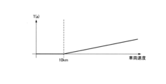
- FIG. 5 is a diagram showing a torque map B used in the vehicle control device according to the first embodiment.
- the acceleration start torque T (a) is a value preset from the inertia of the vehicle, rolling resistance, and the like. However, since the traveling resistance increases as the vehicle speed increases, the acceleration start torque T (a) is calculated by adding the traveling resistance increase shown in the characteristics of FIG. 5 to the preset value.
- step S3 when the base torque T (b) is larger than the acceleration start torque T (a), that is, in the accelerated running state, the driver-required torque T (d) is set as the driver-required torque previous value T (dPre).
- the value obtained by adding the torque change amount ⁇ T (b) is output as it is.
- the base torque change amount ⁇ T (b) is the base torque determined this time (hereinafter, referred to as the base torque current value T (bCur)) and the previously determined base torque (hereinafter, the base torque previous value T). It is described as (bPre).).
- step S4 is the base torque change amount ⁇ T (b) larger than 0 (acceleration running intention) when the base torque T (b) is equal to or less than the acceleration start torque T (a), that is, in the constant speed running state or the decelerated running state? Whether or not it is determined, if it is large, the process proceeds to step S5, and if it is 0 or less (intention to drive at a constant speed or to drive in a decelerated state), the process proceeds to step S6.
- step S5 since the base torque change amount ⁇ T (b) is larger than 0, it is determined that the driver intends to accelerate by stepping on the accelerator pedal, and the base torque T (b) starts accelerating.
- the torque T (a) is reached, the base torque T (b) and the driver-required torque T (d') after limiting the amount of change are controlled to match.
- T (d') T (dPre) + ⁇ (T (a) -T (dPre)) / (T (a) -T (bPre)) ⁇
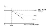
- FIG. 4 is a diagram showing a gain map C used in the vehicle control device according to the first embodiment.
- the gain map C is a gain characteristic diagram in which the horizontal axis represents the steering operation amount (absolute value, which is also referred to as the steering steering angle or simply the steering angle), and the vertical axis represents the torque change amount gain Gst.
- the Gst When the vehicle speed is, for example, 30 km / h or less, it is determined that the steering operation is performed in an intersection or in a parking lot, and it is not necessary to consider the turning characteristics in particular, so the Gst remains 1.
- the Gst When the vehicle speed increases, the Gst is set to decrease as the vehicle speed increases and the steering operation amount increases.
- the steering operation amount is equal to or more than the predetermined operation amount, Gst is set to be constant.
- FIG. 6 is a diagram showing a turning state when the driver operates the accelerator pedal to the foot release side on a road surface having a certain road surface gradient (no road surface gradient) and turns during deceleration running by one-pedal control. ..
- FIG. 6A is a time chart showing the relationship between the accelerator operation amount and the torque acting on the drive wheels.
- the broken line in FIG. 6A shows an example in which the base torque change amount limiting process of the first embodiment is not performed, and the solid line in FIG. 6A shows the base torque change amount limiting process of the first embodiment.
- An example is shown.
- the torque acting on the drive wheels and the torque required by the driver are substantially the same, and are represented as a running state in which restrictions other than the base torque change amount limiting process are not applied.
- FIG. 6B is a schematic view showing a traveling locus when the vehicle turns.
- the broken line in FIG. 6B shows the traveling locus when the base torque change amount limiting process of the first embodiment is not performed, and the solid line in FIG. 6B shows the base torque change amount limiting process of the first embodiment.
- the traveling locus when the above is carried out is shown.
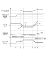
- FIG. 7 is a time chart showing control in one-pedal control deceleration running-constant speed running-acceleration running during turning.
- the vertical axis shows the amount of accelerator operation and the torque acting on the drive wheels from the top.
- the vehicle speed is a predetermined vehicle speed higher than 30 km / h, and the steering operation amount is 30 deg or more in absolute value (that is, Gst is less than 1).
- the horizontal axis is time.
- the times t1 to t3 in this time chart represent the same operating states as the times shown in FIG.
- the solid line shown in the torque column of FIG. 7 indicates the case where the base torque change amount limiting process of the first embodiment is not performed, and the broken line indicates the case where the base torque change amount limiting process of the first embodiment is performed.
- the base torque T (b) becomes the acceleration start torque T (a) as described in step S5.
- the base torque T (b) and the driver-required torque T (d') after limiting the amount of change are controlled to match.
- the base torque T (b) and the driver-required torque T (d') after limiting the amount of change match during the period from the deceleration running state to the accelerating running state of the vehicle, and after the transition to the accelerating running state. Since the base torque T (b) is not limited in the amount of change, it is possible to prevent an increase in the burden on the driver.
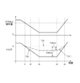
- FIG. 8 is a time chart showing a state in which the vehicle approaches a curve, the accelerator pedal is operated to the foot release side, steering operation is performed during deceleration by one-pedal control, and the vehicle passes through the curve.
- the vertical axis shows the accelerator operation amount, steering angle (steering operation amount), torque acting on the drive wheels, vehicle speed, and yaw rate.
- the horizontal axis is time.
- the solid line shown in the columns of torque, vehicle speed, and yaw rate in FIG. 8 shows the case where the base torque change amount limiting process of the first embodiment is performed, and the broken line shows the case where the base torque change amount limiting process of the first embodiment is not performed.
- the torque starts to decrease by one-pedal control, and the drive torque is switched to the regenerative torque by the time t2, and the deceleration running state is reached. It becomes.
- the steering operation is performed and the turn along the curve is started.
- the base torque T (b) does not change while the accelerator operation amount is constant, and the same regenerative torque is obtained regardless of whether the base torque change amount limiting process is performed or not.
- FIG. 9 is a time chart showing a state in which the vehicle approaches a curve during acceleration, starts steering operation, decelerates by one-pedal control during steering operation, and further decelerates after passing through the curve.
- the vertical axis shows the accelerator operation amount, steering angle (steering operation amount), torque acting on the drive wheels, vehicle speed, and yaw rate.
- the horizontal axis is time.
- the solid line shown in the columns of torque, vehicle speed, and yaw rate in FIG. 9 shows the case where the base torque change amount limiting process of the first embodiment is performed, and the broken line shows the case where the base torque change amount limiting process of the first embodiment is not performed.
- the driver performs a steering operation and starts turning along a curve.
- the base torque T (b) does not change while the accelerator operation amount is constant, and the drive torque is the same regardless of whether the base torque change amount limiting process is performed or not.
- the driver further operates the accelerator pedal to the release side while the steering steering angle is constant, if the base torque change amount limiting process is not performed, the regenerative torque suddenly increases and the vehicle speed increases. The vehicle behavior becomes oversteer due to excessive yaw rate generated as the amount of torque decreases.
- the driver cannot follow the intended turning locus, and the turning locus is returned to the intended locus by repeating the steering operation and the accelerator pedal operation, which may increase the driving load.
- the base torque change amount limiting process of the first embodiment when the base torque change amount limiting process of the first embodiment is performed, the torque change amount with respect to the accelerator pedal operation amount during turning is suppressed, so that the generation of excessive yaw rate can be suppressed. Since the accelerator pedal operation for following the targeted turning locus is facilitated, it is possible to prevent an increase in the driving load on the driver.
- the state in which the deceleration is small as compared with the case where the base torque change amount limiting process is not performed continues. In that state, even if the driver returns the steering steering angle to the neutral position and shifts from the turning state to the straight-ahead state, the gentle deceleration state is maintained.
- the steering steering angle is 30 degrees or less, so the base torque change amount limiting process is not performed and the base torque is set according to the accelerator pedal operation amount. ..
- the torque change amount is not limited, the absolute torque value is affected by the regenerative torque set to be smaller than when the base torque change amount limiting process is not performed, and the vehicle stops in a gradual deceleration state.
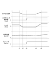
- FIG. 10 is a time chart showing a state in which the vehicle approaches a curve during acceleration, deceleration is started by one-pedal control, steering operation is started, and acceleration is performed. From the top, the vertical axis shows the accelerator operation amount, steering angle (steering operation amount), torque acting on the drive wheels, vehicle speed, and yaw rate. The horizontal axis is time. As shown in FIG. 10, even if the accelerator pedal is released before the steering operation, if the accelerator pedal is not released during the steering operation, the base torque change amount limiting process is performed. Not done. Therefore, the same torque is applied to the vehicle provided with the base torque change amount limiting process of the first embodiment and the vehicle not subjected to the base torque change amount limiting process.
- FIG. 11 is a time chart showing a state in which the vehicle approaches a curve, the accelerator pedal is operated to the foot release side, steering operation is performed during deceleration by one-pedal control, the vehicle passes the curve, and then the vehicle accelerates in a straight-ahead state.
- the vertical axis shows the accelerator operation amount, steering angle (steering operation amount), torque acting on the drive wheels, vehicle speed, and yaw rate.
- the horizontal axis is time.
- the solid line shown in the columns of torque, vehicle speed, and yaw rate in FIG. 11 shows the case where the base torque change amount limiting process of the first embodiment is performed, and the broken line shows the case where the base torque change amount limiting process of the first embodiment is not performed. Since the operations from time t1 to t4 are the same as the operations from time t1 to t4 in FIG. 8 described above, the description thereof will be omitted.
- the base torque T (b) is the acceleration start torque as described in step S5.
- the base torque T (b) and the driver-required torque T (d') after limiting the amount of change are controlled to match.
- the base torque T (b) and the driver-required torque T (d') after limiting the amount of change match during the period from the deceleration running state to the accelerating running state of the vehicle, and after the transition to the accelerating running state. Since the base torque T (b) is not limited in the amount of change, it is possible to prevent an increase in the burden on the driver.
- FIG. 12 is a time chart showing a state in which the vehicle approaches a curve, the accelerator pedal is operated to the foot release side, steering operation is performed during deceleration by one-pedal control, and acceleration is performed in a turning state while passing through the curve.
- the vertical axis shows the accelerator operation amount, steering angle (steering operation amount), torque acting on the drive wheels, vehicle speed, and yaw rate.
- the horizontal axis is time.
- the solid line shown in the columns of torque, vehicle speed, and yaw rate in FIG. 12 shows the case where the base torque change amount limiting process of the first embodiment is performed, and the broken line shows the case where the base torque change amount limiting process of the first embodiment is not performed. Since the operations from time t1 to t4 are the same as the operations from time t1 to t4 in FIG. 11 described above, the description thereof will be omitted.
- the base torque T (b) is the acceleration start torque T.
- the base torque T (b) and the driver-required torque T (d') after limiting the amount of change are controlled to match.
- the base torque T (b) and the driver-required torque T (d') after limiting the amount of change match during the period from the deceleration running state to the accelerating running state of the vehicle, and after the transition to the accelerating running state. Since the base torque T (b) is not limited in the amount of change, it is possible to prevent an increase in the burden on the driver.
- a front motor 3 and a rear motor 7 (hereinafter referred to as an electric motor) that apply regenerative braking force to the wheels of a vehicle, a vehicle control device 17 that requests a control command for controlling the electric motor, and a front motor control.
- a control device for an electric vehicle including the device 18 and the rear motor control device 20 (hereinafter, referred to as a controller).
- the controller is Acquires the accelerator operation amount (first operation information) related to the depressing of the accelerator pedal of the vehicle, Acquires the steering operation amount, which is turning information related to the turning of the vehicle, Based on the accelerator operation amount and the steering operation amount, the base torque change amount ⁇ T (b) (first change rate information) regarding the time change amount of the regenerative braking force with respect to the accelerator pedal operation amount is obtained. Based on the base torque change amount ⁇ T (b), a regenerative braking control command for applying a regenerative braking force to the wheels is output. Therefore, when the vehicle is turning, the operability can be improved when regenerative braking is performed by depressing the accelerator pedal.
- the steering operation amount is detected as the turning information, the turning information may be acquired from, for example, the yaw rate sensor or the deviation of the wheel speeds of the four wheels.
- the controller acquires the steering angle of the vehicle from the turning information and obtains it.
- the steering steering angle exceeds, for example, 30 deg (predetermined steering steering angle)
- the time change amount of the regenerative braking force with respect to the operation amount of the accelerator pedal with respect to the time change amount of the regenerative braking force with respect to the preset operation amount of the accelerator pedal.
- the base torque change amount ⁇ T (b) is obtained so that Therefore, the amount of torque change can be limited according to the turning state, and the operability can be further improved.
- the controller obtains the base torque change amount ⁇ T (b) so that the larger the steering steering angle, the smaller the time change amount of the regenerative braking force with respect to the operation amount of the accelerator pedal.
- the controller obtains the base torque change amount ⁇ T (b) so as to maintain the time change amount of the regenerative braking force with respect to the preset operation amount of the accelerator pedal. That is, when the steering operation amount is less than 30 deg, for example, a lateral force is not required so much, so that it is possible to avoid an unnecessary limitation of the regenerative braking force.
- the controller obtains the base torque change amount ⁇ T (b) so as to maintain the time change amount of the regenerative braking force with respect to the preset accelerator pedal operation amount. .. That is, when the vehicle speed is, for example, 30 km / h or less, it is determined that the steering operation is performed in an intersection or in a parking lot, and since it is not necessary to consider the turning characteristics in particular, it is possible to avoid the limitation of the amount of time change of the unnecessary regenerative braking force. ..
- the controller obtains the base torque change amount ⁇ T (b) so that the time change amount of the regenerative braking force with respect to the preset accelerator pedal operation amount becomes smaller as the vehicle speed increases. That is, the higher the speed of the vehicle, the more it is necessary to secure the lateral force at the time of turning. Therefore, the lateral force can be secured and the operability can be improved by reducing the amount of time change of the regenerative braking force.
- the base torque T (b) and the driver-required torque T (d') after limiting the amount of change match during the period from the deceleration running state to the accelerating running state of the vehicle, and after the transition to the accelerating running state. Since the base torque T (b) is not limited in the amount of change, it is possible to prevent an increase in the burden on the driver.
- the vehicle speed is determined from the rotation speed information of the front wheel resolver 12 that detects the motor rotation speed of the front motor 3 and the rear wheel resolver 13 that detects the motor rotation speed of the rear motor 7. Although it is calculated, the speed of the vehicle may be calculated from the wheel speed sensor 11.
- the control device for an electric vehicle of the present technical idea is in one aspect thereof.
- a control device for an electric vehicle including a control unit that requests a control command for controlling an electric motor that applies regenerative braking force to the wheels of the vehicle.
- the control unit Acquire the first operation information regarding the depressing of the accelerator pedal of the vehicle, Obtaining turning information regarding the turning of the vehicle, Based on the first operation information and the turning information, the first change rate information regarding the time change amount of the regenerative braking force with respect to the operation amount of the accelerator pedal is obtained.
- a regenerative braking control command for applying a regenerative braking force to the wheel is output.
- the control unit When the steering angle of the vehicle is acquired from the turning information and the steering angle exceeds a predetermined steering angle, the accelerator pedal is used with respect to a time change amount of the regenerative braking force with respect to a preset operating amount of the accelerator pedal. The first change rate information is obtained so that the time change amount of the regenerative braking force with respect to the operation amount of is small.
- the control unit The first change rate information is obtained so that the larger the steering angle, the smaller the amount of time change of the regenerative braking force with respect to the operation amount of the accelerator pedal.
- the control unit When the rudder angle is equal to or smaller than the predetermined rudder angle, the first change rate information is provided so as to maintain the time change amount of the regenerative braking force with respect to the preset operation amount of the accelerator pedal. Ask.
- the control unit When the speed of the vehicle is equal to or smaller than the predetermined speed, the first change rate information is obtained so as to maintain the time change amount of the regenerative braking force with respect to the preset operation amount of the accelerator pedal. .. (6) In yet another preferred embodiment, in any of the above embodiments, The control unit The first change rate information is obtained so that the larger the speed of the vehicle, the smaller the amount of time change of the regenerative braking force with respect to the preset operation amount of the accelerator pedal.
- the control unit When the second operation information regarding the depression of the accelerator pedal is acquired after the first operation information is acquired, The second change rate information regarding the time change amount of the driving force with respect to the operation amount of the accelerator pedal is obtained so that the time until the vehicle shifts to acceleration is the same regardless of the turning information, and the second change Based on the rate information, a driving force control command for applying the driving force to the wheels is output.
- the control device for the electric vehicle of the present technical idea is in one aspect thereof.
- a control device for an electric vehicle including a control unit that requests a control command for controlling an electric motor that applies regenerative braking force to the wheels of the vehicle.
- the control unit When the accelerator pedal is stepped back by the occupant of the vehicle, when the occupant of the vehicle operates the steering wheel, the time change of the regenerative braking force with respect to the operation amount of the accelerator pedal is compared with the case where the steering wheel is not operated. A regenerative braking control command is output so that the amount becomes small.
- the control method of the electric vehicle of the present technical idea is, in one aspect thereof. It ’s a vehicle control method. Acquires the operation information regarding the depressing of the accelerator pedal of the vehicle, and obtains the operation information.
- the change rate information regarding the time change amount of the regenerative braking force with respect to the operation amount of the accelerator pedal is obtained, and the regenerative braking force is applied to the wheel based on the change rate information.
- the steering angle of the vehicle is acquired from the turning information, and the steering angle of the vehicle is acquired. When the steering angle exceeds a predetermined steering angle, the time change amount of the regenerative braking force with respect to the operation amount of the accelerator pedal becomes smaller than the time change amount of the regenerative braking force with respect to the preset operation amount of the accelerator pedal.
- the change rate information is obtained as described above.
- the control system of the electric vehicle of the present technical idea is in one aspect thereof.
- An electric motor that applies regenerative braking force to the wheels of the vehicle,
- a controller that requests a control command for controlling the electric motor.
- Acquires the operation information regarding the depressing of the accelerator pedal of the vehicle and obtains the operation information.
- Obtaining turning information regarding the turning of the vehicle Based on the operation information and the turning information, the change rate information regarding the time change amount of the regenerative braking force with respect to the operation amount of the accelerator pedal is obtained.
- a regenerative braking control command for applying a regenerative braking force to the wheel is output. With the controller To be equipped.
- the controller When the steering angle of the vehicle is acquired from the turning information and the steering angle exceeds a predetermined steering angle, the accelerator pedal is used with respect to a time change amount of the regenerative braking force with respect to a preset operating amount of the accelerator pedal.
- the change rate information is obtained so that the time change amount of the regenerative braking force with respect to the operation amount of is small.
- the present invention is not limited to the above-described embodiment, and includes various modifications.
- the above-described embodiment has been described in detail in order to explain the present invention in an easy-to-understand manner, and is not necessarily limited to the one including all the described configurations.
- it is possible to replace a part of the configuration of one embodiment with the configuration of another embodiment and it is also possible to add the configuration of another embodiment to the configuration of one embodiment.
Landscapes
- Engineering & Computer Science (AREA)
- Transportation (AREA)
- Mechanical Engineering (AREA)
- Power Engineering (AREA)
- Automation & Control Theory (AREA)
- Chemical & Material Sciences (AREA)
- Combustion & Propulsion (AREA)
- Physics & Mathematics (AREA)
- Electromagnetism (AREA)
- Electric Propulsion And Braking For Vehicles (AREA)
- Control Of Driving Devices And Active Controlling Of Vehicle (AREA)
Abstract
本発明の一実施形態における電動車両の制御装置、制御方法および制御システムは、車両のアクセルペダルの踏み戻しに関する操作情報と、車両の旋回に関する旋回情報と、に基づいてアクセルペダルの操作量に対する回生制動力の時間変化量に関する変化率情報を求め、変化率情報に基づいて、車輪に回生制動力を付与するための回生制動制御指令を出力することとした。
Description
本発明は、電動車両の制御装置、電動車両の制御方法および電動車両の制御システムに関する。
単一のペダルにアクセルペダルとブレーキペダルの双方の機能を持たせ、運転者が当該単一のペダルをそのストロークの所定位置から踏み込んだ場合に車両を加速し、所定位置から踏み戻した場合に車両を減速するワンペダル制御を行う技術が知られている。
特許文献1には、車体速度が小さいほど、該所定位置をアクセルペダルの非操作側にシフトするように設定することが開示されている。
特許文献1には、車体速度が小さいほど、該所定位置をアクセルペダルの非操作側にシフトするように設定することが開示されている。
しかしながら、上記特許文献1では、駆動力と制動力とが切り替わるアクセルペダルのストローク量を車体速度に応じて変えているに過ぎず、車両が旋回する際のドライバーによる操作性については何ら考慮されていない。
本発明の目的の一つは、車両の旋回時において、アクセルペダルの踏み戻しによる回生制動を行う際に操作性を向上させることができる電動車両の制御装置、電動車両の制御方法及び電動車両の制御システムを提供することにある。
本発明の目的の一つは、車両の旋回時において、アクセルペダルの踏み戻しによる回生制動を行う際に操作性を向上させることができる電動車両の制御装置、電動車両の制御方法及び電動車両の制御システムを提供することにある。
本発明の一実施形態における電動車両の制御装置、制御方法および制御システムは、車両のアクセルペダルの踏み戻しに関する操作情報と、車両の旋回に関する旋回情報と、に基づいてアクセルペダルの操作量に対する回生制動力の時間変化量に関する変化率情報を求め、変化率情報に基づいて、車輪に回生制動力を付与するための回生制動制御指令を出力することとした。
本発明の一実施形態によれば、車両の旋回時において、アクセルペダルの踏み戻しによる回生制動を行う際に操作性を向上させることができる。
〔実施形態1〕
図1は、実施形態1における電動車両の制御システムの構成図である。
電動車両1は、前輪2FL、2FRにトルクを出力するフロントモータ(前輪用電動モータ)3を有する。フロントモータ3および前輪2FL、2FR間の動力伝達は、減速機4、ディファレンシャル5およびフロント車軸6FL、6FRを介して行われる。
電動車両1は、後輪2RL、2RRにトルクを出力するリアモータ(後輪用電動モータ)7を有する。尚、前輪2FL、2FR及び後輪2RL、2RRを総称して駆動輪2とも記載する。リアモータ7および後輪2RL、2RR間の動力伝達は、減速機8、ドグクラッチ9、ディファレンシャル10およびリア車軸6RL、6RRを介して行われる。
ドグクラッチ9が締結されている場合には、リアモータ7および後輪2RL、2RR間で動力が伝達される。
一方、ドグクラッチ9が解放されている場合には、リアモータ7および後輪2RL、2RR間で動力は伝達されない。
各車輪2FL、2FR、2RL、2RRは、車輪速を検出する車輪速センサ11FL、11FR、11RL、11RRを有する。フロントモータ3は、モータ回転数を検出する前輪用レゾルバ12を有する。リアモータ7は、モータ回転数を検出する後輪用レゾルバ13を有する。
電動車両1は、低電圧バッテリ14および高電圧バッテリ15を有する。低電圧バッテリ14は、例えば鉛蓄電池である。高電圧バッテリ15は、例えばリチウムイオン電池またはニッケル水素電池である。高電圧バッテリ15は、DC-DCコンバータ16により昇圧された電力により充電される。
電動車両1は、車両制御装置17、フロントモータ制御装置18、リアモータ制御装置20およびバッテリ制御装置19を有する。各制御装置17、18、19、20は、CANバス21を介してお互いに情報を共有する。
車両制御装置17は、前輪用レゾルバ12、後輪用レゾルバ13、アクセル操作量を検出するアクセルペダルセンサ22、ブレーキ操作量を検出するブレーキセンサ23、ギヤ位置センサ24等の各種センサから情報を取得し、車両の統合制御を行う。車両制御装置17は、ドライバのアクセル操作やブレーキ操作等に応じた要求トルクに対し、要求配分トルクに応じてフロントモータ3が出力すべきフロント要求トルクおよびリアモータ7が出力すべきリア要求トルクを算出する。
要求配分トルクは、前輪2FL、2FRおよび後輪2RL、2RRのトルク配分比の要求値であって、走行状態に応じて適宜設定される。尚、フロント要求トルク及びリア要求トルクを総称して運転者要求トルクとも記載する。
フロントモータ制御装置18は、フロント要求トルクに基づいてフロントモータ3に供給する電力を制御する。リアモータ制御装置20は、リア要求トルクに基づいてリアモータ7に供給する電力を制御する。
バッテリ制御装置19は、高電圧バッテリ15の充放電状態および高電圧バッテリ15を構成する単電池セルを監視する。バッテリ制御装置19は、高電圧バッテリ15の充放電状態等に基づいて、バッテリ要求トルク制限値を算出する。バッテリ要求トルク制限値は、フロントモータ3、リアモータ7において許容する最大トルクである。例えば高電圧バッテリ15の充電量が低下しているときには、通常よりもバッテリ要求トルク制限値を小さな値に設定する。
バッテリ制御装置19は、高電圧バッテリ15の充放電状態および高電圧バッテリ15を構成する単電池セルを監視する。バッテリ制御装置19は、高電圧バッテリ15の充放電状態等に基づいて、バッテリ要求トルク制限値を算出する。バッテリ要求トルク制限値は、フロントモータ3、リアモータ7において許容する最大トルクである。例えば高電圧バッテリ15の充電量が低下しているときには、通常よりもバッテリ要求トルク制限値を小さな値に設定する。
図2は、実施形態1における車両制御装置17の駆動トルク算出処理を表す制御ブロック図である。
運転者要求トルク算出処理部101では、車両速度とアクセル操作量とに基づいて運転者要求トルクを算出する。尚、本処理部における算出の詳細については後述する。尚、車両速度は、前輪用レゾルバ12または後輪用レゾルバ13からの各電動モータ3、7の取得した回転数情報から、推定した車両速度を算定するが、他のセンサから算出してもよい。
回生協調ブレーキ要求トルク受け入れ処理部102では、運転者要求トルク算出処理部101において算出された運転者要求トルクから、ブレーキ操作量に基づいて算出された回生協調ブレーキ要求トルク分を減算し、回生協調ブレーキ受け入れ後トルクを算出する。
スリップ制御トルク算出処理部103では、車両速度とスリップ制御目標車輪速度から加速時における駆動トルク制限値もしくは減速時における制動トルク制限値を算出し、回生協調ブレーキ受け入れ以後トルクが上記制限値の範囲内となるように制限したスリップ制御トルクを算出する。
トルク制限処理部104では、バッテリ要求トルク制限値等の各種トルク制限値によってスリップ制御トルクを制限し、指令トルクとして制限後駆動トルクを出力する。尚、制限後駆動トルクとは、車両の加速側と減速側の両方のトルクを含む。
図3は、実施形態1における運転者要求トルク算出時におけるベーストルク変化量制限処理を表すフローチャートである。
ステップS1では、アクセルペダルのストロークを検出するアクセルペダルセンサ22から取得したアクセルペダルの踏み戻しに関するアクセル操作量情報と車両速度からワンペダル制御の基準となる各電動モータ3,7のベーストルクT(b)をあらかじめ定められたトルクマップAにより算出する。なお、ベーストルクT(b)は、車両速度とアクセルペダルのストロークで一意に決まり、平坦路でアクセルペダルから完全に足離しすると、走行状態から停車するまで減速可能なトルクとして設定している。
ステップS1では、アクセルペダルのストロークを検出するアクセルペダルセンサ22から取得したアクセルペダルの踏み戻しに関するアクセル操作量情報と車両速度からワンペダル制御の基準となる各電動モータ3,7のベーストルクT(b)をあらかじめ定められたトルクマップAにより算出する。なお、ベーストルクT(b)は、車両速度とアクセルペダルのストロークで一意に決まり、平坦路でアクセルペダルから完全に足離しすると、走行状態から停車するまで減速可能なトルクとして設定している。
ステップS2では、ベーストルクT(b)がトルクマップBにより決定したトルクより大きいか否かを判断し、大きい場合はステップS3に進み、それ以外の場合はステップS4に進む。図5は、実施形態1における車両制御装置で使用するトルクマップBを表す図である。トルクマップBは、車両が加速に転じるトルク(以下、加速開始トルクT(a)と記載する。)が設定されている。加速開始トルクT(a)は、車両のイナーシャと転がり抵抗等から予め設定された値である。ただし、車両速度が増加すると走行抵抗が増加するため、加速開始トルクT(a)は、予め設定された値に図5の特性に示す走行抵抗増大分を加算することで算出する。
ステップS3では、ベーストルクT(b)が加速開始トルクT(a)より大きい、すなわち加速走行状態のとき、運転者要求トルクT(d)として、運転者要求トルク前回値T(dPre)にベーストルク変化量ΔT(b)を加算した値をそのまま出力する。ここで、ベーストルク変化量ΔT(b)は、今回決定されたベーストルク(以下、ベーストルク今回値T(bCur)と記載する。)と前回決定されたベーストルク(以下、ベーストルク前回値T(bPre)と記載する。)との差である。
ステップS4では、ベーストルクT(b)が加速開始トルクT(a)以下、すなわち定速走行状態もしくは減速走行状態のとき、ベーストルク変化量ΔT(b)が0より大きい(加速走行意図)か否かを判断し、大きい場合はステップS5に進み、0以下(定速走行意図もしくは減速走行意図)の場合はステップS6に進む。
ステップS5では、ベーストルク変化量ΔT(b)が0より大きいため、運転者がアクセルペダルを踏み増して加速走行を意図している場合であると判断し、ベーストルクT(b)が加速開始トルクT(a)に到達するときに、ベーストルクT(b)と変化量制限後運転者要求トルクT(d')とが一致するように制御する。具体的には、変化量制限後運転者要求トルクT(d')として、以下の関係式(1)から算出する。[関係式(1)]T(d')=T(dPre)+{(T(a)-T(dPre))/(T(a)-T(bPre))}
ステップS6では、ベーストルク変化量ΔT(b)が0以下のため、運転者がアクセルペダルを維持もしくは足離し側に操作して定速走行もしくは減速走行を意図している場合であると判断し、ベーストルク変化量ΔT(b)を制限した変化量制限後運転者要求トルクT(d')として、以下の関係式(2)から算出する。[関係式(2)]T(d')=T(dPre)+ΔT(b)×Gst
ここで、Gstは、ステアリングゲインである。図4は、実施形態1における車両制御装置で使用するゲインマップCを表す図である。ゲインマップCは、横軸にステアリング操作量(絶対値であり、ステアリング操舵角もしくは単に舵角とも記載する。)を取り、縦軸にトルク変化量ゲインGstを取ったゲイン特性図である。ゲインマップCには、ステアリング操作量が30deg以上となると、Gst=1から1より小さな所定ゲインまで減少する特性が設定されている。言い換えると、ステアリング操作量が30deg未満では、さほど横力を必要とされないため、不要な回生制動力の制限を回避する。また、ゲインマップCには、車両速度毎に複数のゲイン特性が設定されている。車両速度が例えば30km/h以下では、交差点内や駐車場でのステアリング操作と判断され、特に旋回特性を考慮する必要がないため、Gstは1のままである。車両速度が上昇すると、車両速度が高いほど、またステアリング操作量が大きいほどGstが小さくなるように設定されている。尚、ステアリング操作量が所定操作量以上では、Gstが一定となるように設定されている。これにより、運転者が減速走行中にステアリング操作を行った場合、運転者要求トルクの変化量が過度に制限されることを回避する。
ここで、Gstは、ステアリングゲインである。図4は、実施形態1における車両制御装置で使用するゲインマップCを表す図である。ゲインマップCは、横軸にステアリング操作量(絶対値であり、ステアリング操舵角もしくは単に舵角とも記載する。)を取り、縦軸にトルク変化量ゲインGstを取ったゲイン特性図である。ゲインマップCには、ステアリング操作量が30deg以上となると、Gst=1から1より小さな所定ゲインまで減少する特性が設定されている。言い換えると、ステアリング操作量が30deg未満では、さほど横力を必要とされないため、不要な回生制動力の制限を回避する。また、ゲインマップCには、車両速度毎に複数のゲイン特性が設定されている。車両速度が例えば30km/h以下では、交差点内や駐車場でのステアリング操作と判断され、特に旋回特性を考慮する必要がないため、Gstは1のままである。車両速度が上昇すると、車両速度が高いほど、またステアリング操作量が大きいほどGstが小さくなるように設定されている。尚、ステアリング操作量が所定操作量以上では、Gstが一定となるように設定されている。これにより、運転者が減速走行中にステアリング操作を行った場合、運転者要求トルクの変化量が過度に制限されることを回避する。
図6は、ある一定の路面勾配(路面勾配なし)を有する路面上で運転者がアクセルペダルを足離し側に操作し、ワンペダル制御による減速走行中に旋回した場合における旋回状態を表す図である。図6(a)は、アクセル操作量及び駆動輪に作用するトルクとの関係を表すタイムチャートである。図6(a)中の破線は、実施形態1のベーストルク変化量制限処理を実施しない例を示し、図6(a)中の実線は、実施形態1のベーストルク変化量制限処理を実施した例を示す。また、駆動輪に作用するトルクと運転者要求トルクとは略一致しており、ベーストルク変化量制限処理以外の他の制限等が行われていない走行状態として表される。図6(b)は、車両の旋回時における走行軌跡を表す概略図である。図6(b)中の破線は、実施形態1のベーストルク変化量制限処理を実施しない場合の走行軌跡を示し、図6(b)中の実線は、実施形態1のベーストルク変化量制限処理を実施した場合の走行軌跡を示す。
図6(a)の破線で示すように、アクセル操作が一定状態からアクセルペダルを足離し側に操作すると、アクセル操作量に応じて駆動輪に作用するトルクが減少し、回生トルクを発生する。このとき、駆動輪の摩擦円内において、前後方向の制動力成分が大きくなると左右方向の横力成分が小さくなり、車両がアンダーステア傾向となる。
時刻t2において、運転者がアンダーステア傾向を回避するためにアクセルペダルを若干踏み込み、回生トルクを弱めて制動力成分を小さくすることで横力を確保し、運転者のステアリング操作量に見合った理想の走行軌跡に復帰しようと試みる。よって、図6(a)及び図6(b)の破線に示すように、アクセルペダルの踏み込み量とステアリング操作量の両方を複雑に操作して理想の走行軌跡を維持する必要があり、安定した旋回走行状態を得ることが困難となる。また、ワンペダル制御を備えていない一般的な車両を運転する際、旋回中のアンダーステアが発生すると、通常はアクセルペダルを足離し側に操作する。つまり、ワンペダル制御実施時における旋回中は、一般的な車両を運転する場合と逆のアクセルペダル操作が必要となり、運転者への負担が大きくなるおそれがある。
時刻t2において、運転者がアンダーステア傾向を回避するためにアクセルペダルを若干踏み込み、回生トルクを弱めて制動力成分を小さくすることで横力を確保し、運転者のステアリング操作量に見合った理想の走行軌跡に復帰しようと試みる。よって、図6(a)及び図6(b)の破線に示すように、アクセルペダルの踏み込み量とステアリング操作量の両方を複雑に操作して理想の走行軌跡を維持する必要があり、安定した旋回走行状態を得ることが困難となる。また、ワンペダル制御を備えていない一般的な車両を運転する際、旋回中のアンダーステアが発生すると、通常はアクセルペダルを足離し側に操作する。つまり、ワンペダル制御実施時における旋回中は、一般的な車両を運転する場合と逆のアクセルペダル操作が必要となり、運転者への負担が大きくなるおそれがある。
これに対し、図6(a)の実線で示すように、時刻t1において、駆動輪に作用するトルクが加速開始トルク(本例では0)未満となると、実線で示す実施形態1の場合、旋回状態であるためステアリングゲインGstが1よりも小さい値に設定され、ベーストルク変化量ΔT(b)が制限されるため、トルク減少量が緩やかに設定され、回生トルクが抑制される。よって、駆動輪の摩擦円内において、前後方向の制動力成分が抑制され、左右方向の横力成分の減少を抑制できるため、車両のアンダーステア傾向を回避できる。よって、図6(a)及び図6(b)の実線に示すように、アクセルペダルの戻し量とステアリング操作量の両方を複雑に制御することなく理想の走行軌跡を維持することができ、安定した旋回走行状態を得ることができる。
図7は、旋回中におけるワンペダル制御の減速走行―定速走行―加速走行における制御を示すタイムチャートである。縦軸は、上からアクセル操作量、駆動輪に作用するトルクを示している。車両速度は30km/hより高い所定車速であり、ステアリング操作量は絶対値で30deg以上(すなわち、Gstは1未満)である。横軸は、時間である。本タイムチャートの時刻t1~t3は図6に示す時刻と同じ作動状態を表す。ただし、図7のトルクの欄で示す実線が実施形態1のベーストルク変化量制限処理を実施しない場合を、破線が実施形態1のベーストルク変化量制限処理を実施した場合を示す。
旋回中のアクセルペダルの足離し側への操作(減速走行意図)に対するベーストルク変化量を制限した場合、ベーストルクT(b)と変化量制限後運転者要求トルクT(d')とは乖離しているため、回生トルク発生時に回生トルクを変化量制限のないベーストルクT(b)に向けてスムーズに復帰させる必要がある。特に、ベーストルクT(b)が減速走行状態から加速走行状態に移行するとき、すなわち運転者の意図が加速意図に転じているときに、変化量制限後運転者要求トルクT(d')として回生トルクが継続すると、運転者に違和感を与えるおそれがある。そこで、図7の時刻t4において運転者がアクセルペダルを踏み込み、アクセル操作量が加速走行意図を示すと、ステップS5で説明したように、ベーストルクT(b)が加速開始トルクT(a)に到達するときに、ベーストルクT(b)と変化量制限後運転者要求トルクT(d')とが一致するように制御する。これにより、車両が減速走行状態から加速走行状態に移行するまでの間にベーストルクT(b)と変化量制限後運転者要求トルクT(d')とが一致し、加速走行状態に移行後は、ベーストルクT(b)に変化量制限がかかることがないため、運転者への負担増大を防止できる。
図8は、車両がカーブに差し掛かり、アクセルペダルを足離し側に操作し、ワンペダル制御により減速中にステアリング操作を実施してカーブを通過する状態を示すタイムチャートである。縦軸は、上からアクセル操作量、ステアリング操舵角(ステアリング操作量)、駆動輪に作用するトルク、車両速度、ヨーレートを示している。横軸は、時間である。図8のトルク、車両速度、ヨーレートの欄で示す実線が実施形態1のベーストルク変化量制限処理を実施した場合を、破線が実施形態1のベーストルク変化量制限処理を実施しない場合を示す。
直進・加速走行状態の時刻t1において、運転者がアクセルペダルを足離し側に操作すると、ワンペダル制御によりトルクは減少を開始し、時刻t2までの間に駆動トルクから回生トルクに切り替わり、減速走行状態となる。
時刻t3において、ステアリング操作を行い、カーブに沿った旋回を開始する。このとき、アクセル操作量が一定の間は、ベーストルクT(b)も変化せず、ベーストルク変化量制限処理を実施した場合も実施しない場合も同じ回生トルクとなる。
時刻t3において、ステアリング操作を行い、カーブに沿った旋回を開始する。このとき、アクセル操作量が一定の間は、ベーストルクT(b)も変化せず、ベーストルク変化量制限処理を実施した場合も実施しない場合も同じ回生トルクとなる。
時刻t4において、運転者がステアリング操舵角を一定とした状態で更にアクセルペダルを足離し側に操作した際、ベーストルク変化量制限処理を実施しない場合には、回生トルクが一気に大きくなり、車両速度の減少と共にヨーレートが過剰に発生することで車両挙動がオーバーステアとなる。そうすると、運転者は意図した旋回軌跡を辿ることができず、ステアリング操作やアクセルペダル操作を繰り返すことで旋回軌跡を意図した軌跡に復帰させることになるため、運転負荷が増大するおそれがあった。
これに対し、実施形態1のベーストルク変化量制限処理を実施した場合には、旋回中のアクセルペダル操作量に対するトルク変化量が抑制されるため、過剰なヨーレートの発生を抑制することができ、狙った旋回軌跡をたどるためのアクセルペダル操作が容易となるため、運転者への運転負荷の増大を防止できる。
これに対し、実施形態1のベーストルク変化量制限処理を実施した場合には、旋回中のアクセルペダル操作量に対するトルク変化量が抑制されるため、過剰なヨーレートの発生を抑制することができ、狙った旋回軌跡をたどるためのアクセルペダル操作が容易となるため、運転者への運転負荷の増大を防止できる。
図9は、加速中に車両がカーブに差し掛かり、ステアリング操作を開始し、ステアリング操作中にワンペダル制御により減速し、カーブを通過後に更に減速する状態を示すタイムチャートである。縦軸は、上からアクセル操作量、ステアリング操舵角(ステアリング操作量)、駆動輪に作用するトルク、車両速度、ヨーレートを示している。横軸は、時間である。図9のトルク、車両速度、ヨーレートの欄で示す実線が実施形態1のベーストルク変化量制限処理を実施した場合を、破線が実施形態1のベーストルク変化量制限処理を実施しない場合を示す。
直進・加速走行状態の時刻t1において、運転者がステアリング操作を行い、カーブに沿った旋回を開始する。このとき、アクセル操作量が一定の間は、ベーストルクT(b)も変化せず、ベーストルク変化量制限処理を実施した場合も実施しない場合も同じ駆動トルクとなる。
時刻t2において、運転者がステアリング操舵角を一定とした状態で更にアクセルペダルを足離し側に操作した際、ベーストルク変化量制限処理を実施しない場合には、回生トルクが一気に大きくなり、車両速度の減少と共にヨーレートが過剰に発生することで車両挙動がオーバーステアとなる。そうすると、運転者は意図した旋回軌跡を辿ることができず、ステアリング操作やアクセルペダル操作を繰り返すことで旋回軌跡を意図した軌跡に復帰させることになるため、運転負荷が増大するおそれがあった。
これに対し、実施形態1のベーストルク変化量制限処理を実施した場合には、旋回中のアクセルペダル操作量に対するトルク変化量が抑制されるため、過剰なヨーレートの発生を抑制することができ、狙った旋回軌跡をたどるためのアクセルペダル操作が容易となるため、運転者への運転負荷の増大を防止できる。
尚、時刻t3以降、運転者がアクセルペダル操作を一定とすると、ベーストルク変化量制限処理を実施しない場合に比べて小さな減速度が発生した状態が継続する。その状態で運転者がステアリング操舵角を中立位置に戻して旋回状態から直進状態に移行しても、緩やかな減速状態が維持される。
時刻t4において、運転者がアクセルペダルから足離しをすると、ステアリング操舵角は30度以下であるため、ベーストルク変化量制限処理は実施されず、アクセルペダル操作量に応じてベーストルクが設定される。ただし、トルク変化量に制限はかからないものの、トルク絶対値はベーストルク変化量制限処理を実施しない場合に比べて小さく設定された回生トルクが作用し、緩やかな減速状態で車両停止する。
時刻t4において、運転者がアクセルペダルから足離しをすると、ステアリング操舵角は30度以下であるため、ベーストルク変化量制限処理は実施されず、アクセルペダル操作量に応じてベーストルクが設定される。ただし、トルク変化量に制限はかからないものの、トルク絶対値はベーストルク変化量制限処理を実施しない場合に比べて小さく設定された回生トルクが作用し、緩やかな減速状態で車両停止する。
図10は、加速中に車両がカーブに差し掛かり、ワンペダル制御により減速開始後、ステアリング操作を開始し、加速する状態を示すタイムチャートである。縦軸は、上からアクセル操作量、ステアリング操舵角(ステアリング操作量)、駆動輪に作用するトルク、車両速度、ヨーレートを示している。横軸は、時間である。図10に示すように、ステアリング操作前にアクセルペダルを緩める操作が実施された場合であっても、ステアリング操作中にアクセルペダルを緩める操作が実施されない場合には、ベーストルク変化量制限処理が実施されない。よって、実施形態1のベーストルク変化量制限処理を備えた車両と、ベーストルク変化量制限処理を実施しない車両とは、同じトルクが付与される。
図11は、車両がカーブに差し掛かり、アクセルペダルを足離し側に操作し、ワンペダル制御により減速中にステアリング操作を実施してカーブを通過後、直進状態で加速する状態を示すタイムチャートである。縦軸は、上からアクセル操作量、ステアリング操舵角(ステアリング操作量)、駆動輪に作用するトルク、車両速度、ヨーレートを示している。横軸は、時間である。図11のトルク、車両速度、ヨーレートの欄で示す実線が実施形態1のベーストルク変化量制限処理を実施した場合を、破線が実施形態1のベーストルク変化量制限処理を実施しない場合を示す。尚、時刻t1~t4までの動作は、上述の図8の時刻t1~t4と同じ動作であるため、説明を省略する。
時刻t2以降において、旋回中のアクセルペダルの足離し側への操作(減速走行意図)に対するベーストルク変化量を制限した場合、ベーストルクT(b)と変化量制限後運転者要求トルクT(d')とは乖離しているため、回生トルク発生時に回生トルクを変化量制限のないベーストルクT(b)に向けてスムーズに復帰させる必要がある。特に、ベーストルクT(b)が減速走行状態から加速走行状態に移行するとき、すなわち運転者の意図が加速意図に転じているときに、変化量制限後運転者要求トルクT(d')として回生トルクが継続すると、運転者に違和感を与えるおそれがある。
そこで、図11の時刻t5において、旋回終了後、運転者がアクセルペダルを踏み込み、アクセル操作量が加速走行意図を示すと、ステップS5で説明したように、ベーストルクT(b)が加速開始トルクT(a)に到達する時刻t6において、ベーストルクT(b)と変化量制限後運転者要求トルクT(d')とが一致するように制御する。これにより、車両が減速走行状態から加速走行状態に移行するまでの間にベーストルクT(b)と変化量制限後運転者要求トルクT(d')とが一致し、加速走行状態に移行後は、ベーストルクT(b)に変化量制限がかかることがないため、運転者への負担増大を防止できる。
そこで、図11の時刻t5において、旋回終了後、運転者がアクセルペダルを踏み込み、アクセル操作量が加速走行意図を示すと、ステップS5で説明したように、ベーストルクT(b)が加速開始トルクT(a)に到達する時刻t6において、ベーストルクT(b)と変化量制限後運転者要求トルクT(d')とが一致するように制御する。これにより、車両が減速走行状態から加速走行状態に移行するまでの間にベーストルクT(b)と変化量制限後運転者要求トルクT(d')とが一致し、加速走行状態に移行後は、ベーストルクT(b)に変化量制限がかかることがないため、運転者への負担増大を防止できる。
図12は、車両がカーブに差し掛かり、アクセルペダルを足離し側に操作し、ワンペダル制御により減速中にステアリング操作を実施してカーブを通過中に旋回状態で加速する状態を示すタイムチャートである。縦軸は、上からアクセル操作量、ステアリング操舵角(ステアリング操作量)、駆動輪に作用するトルク、車両速度、ヨーレートを示している。横軸は、時間である。図12のトルク、車両速度、ヨーレートの欄で示す実線が実施形態1のベーストルク変化量制限処理を実施した場合を、破線が実施形態1のベーストルク変化量制限処理を実施しない場合を示す。尚、時刻t1~t4までの動作は、上述の図11の時刻t1~t4と同じ動作であるため、説明を省略する。
時刻t2以降において、旋回中のアクセルペダルの足離し側への操作(減速走行意図)に対するベーストルク変化量を制限した場合、ベーストルクT(b)と変化量制限後運転者要求トルクT(d')とは乖離しているため、回生トルク発生時に回生トルクを変化量制限のないベーストルクT(b)に向けてスムーズに復帰させる必要がある。特に、ベーストルクT(b)が減速走行状態から加速走行状態に移行するとき、すなわち運転者の意図が加速意図に転じているときに、変化量制限後運転者要求トルクT(d')として回生トルクが継続すると、運転者に違和感を与えるおそれがある。
そこで、図12の時刻t5において、旋回中に運転者がアクセルペダルを踏み込み、アクセル操作量が加速走行意図を示すと、ステップS5で説明したように、ベーストルクT(b)が加速開始トルクT(a)に到達する時刻t6において、ベーストルクT(b)と変化量制限後運転者要求トルクT(d')とが一致するように制御する。これにより、車両が減速走行状態から加速走行状態に移行するまでの間にベーストルクT(b)と変化量制限後運転者要求トルクT(d')とが一致し、加速走行状態に移行後は、ベーストルクT(b)に変化量制限がかかることがないため、運転者への負担増大を防止できる。
そこで、図12の時刻t5において、旋回中に運転者がアクセルペダルを踏み込み、アクセル操作量が加速走行意図を示すと、ステップS5で説明したように、ベーストルクT(b)が加速開始トルクT(a)に到達する時刻t6において、ベーストルクT(b)と変化量制限後運転者要求トルクT(d')とが一致するように制御する。これにより、車両が減速走行状態から加速走行状態に移行するまでの間にベーストルクT(b)と変化量制限後運転者要求トルクT(d')とが一致し、加速走行状態に移行後は、ベーストルクT(b)に変化量制限がかかることがないため、運転者への負担増大を防止できる。
実施形態1の電動車両の制御装置、制御方法および制御システムにあっては、以下に列挙する作用効果を奏する。
(1)車両の車輪に回生制動力を付与するフロントモータ3及びリアモータ7(以下、電動モータと記載する。)と、電動モータを制御するための制御指令を求める車両制御装置17,フロントモータ制御装置18,リアモータ制御装置20(以下、コントローラと記載する。)を備える電動車両の制御装置であって、
コントローラは、
車両のアクセルペダルの踏み戻しに関するアクセル操作量(第1操作情報)を取得し、
車両の旋回に関する旋回情報であるステアリング操作量を取得し、
アクセル操作量と、ステアリング操作量と、に基づいてアクセルペダルの操作量に対する回生制動力の時間変化量に関するベーストルク変化量ΔT(b)(第1変化率情報)を求め、
ベーストルク変化量ΔT(b)に基づいて、車輪に回生制動力を付与するための回生制動制御指令を出力する。
よって、車両の旋回時において、アクセルペダルの踏み戻しによる回生制動を行う際に操作性を向上させることができる。尚、旋回情報としてステアリング操作量を検出したが、例えばヨーレートセンサや4輪の車輪速の偏差から旋回情報を取得してもよい。
(2)コントローラは、旋回情報のうち車両のステアリング操舵角を取得し、
ステアリング操舵角が例えば30deg(所定ステアリング操舵角)を超える場合、予め設定されたアクセルペダルの操作量に対する回生制動力の時間変化量に対して、アクセルペダルの操作量に対する回生制動力の時間変化量が小さくなるようにベーストルク変化量ΔT(b)を求める。
よって、旋回状態に応じてトルク変化量を制限することができ、より操作性を向上できる。
(3)コントローラは、ステアリング操舵角が大きいほど、アクセルペダルの操作量に対する回生制動力の時間変化量が小さくなるようにベーストルク変化量ΔT(b)を求める。
よって、ステアリング操舵角が大きくなるほど回生制動力の変化を制限するため、より車輪の横力が必要な状態での操作性を向上できる。
(4)コントローラは、ステアリング操舵角が30度以下の場合、予め設定されたアクセルペダルの操作量に対する回生制動力の時間変化量を維持するようにベーストルク変化量ΔT(b)を求める。
すなわち、ステアリング操作量が例えば30deg未満では、さほど横力を必要とされないため、不要な回生制動力の制限を回避できる。
(5)コントローラは、車両の速度が例えば30km/h以下の場合、予め設定されたアクセルペダルの操作量に対する回生制動力の時間変化量を維持するようにベーストルク変化量ΔT(b)を求める。
すなわち、車両速度が例えば30km/h以下では、交差点内や駐車場でのステアリング操作と判断され、特に旋回特性を考慮する必要がないため、不要な回生制動力の時間変化量の制限を回避できる。
(6)コントローラは、車両の速度が大きいほど、予め設定されたアクセルペダルの操作量に対する回生制動力の時間変化量が小さくようにベーストルク変化量ΔT(b)を求める。
すなわち、車両の速度が大きいほど、旋回時における横力を確保する必要があるため、回生制動力の時間変化量を小さくすることで横力を確保でき、操作性を向上できる。
すなわち、車両速度が例えば30km/h以下では、交差点内や駐車場でのステアリング操作と判断され、特に旋回特性を考慮する必要がないため、不要な回生制動力の時間変化量の制限を回避できる。
(6)コントローラは、車両の速度が大きいほど、予め設定されたアクセルペダルの操作量に対する回生制動力の時間変化量が小さくようにベーストルク変化量ΔT(b)を求める。
すなわち、車両の速度が大きいほど、旋回時における横力を確保する必要があるため、回生制動力の時間変化量を小さくすることで横力を確保でき、操作性を向上できる。
(7)コントローラは、アクセルペダルの踏み戻しに関するアクセル操作量を取得した後、アクセルペダルの踏み込みに関するアクセル操作量(第2操作情報)を取得した場合、
車両が加速に移行するまでの時間が旋回情報に関わらず同じになるように、アクセルペダルの操作量に対する駆動力の時間変化量に関する変化量制限後運転者要求トルクT(d')(第2変化率情報)を求め、
変化量制限後運転者要求トルクT(d')に基づいて、車輪に駆動力を付与するための駆動力制御指令を出力する。
これにより、車両が減速走行状態から加速走行状態に移行するまでの間にベーストルクT(b)と変化量制限後運転者要求トルクT(d')とが一致し、加速走行状態に移行後は、ベーストルクT(b)に変化量制限がかかることがないため、運転者への負担増大を防止できる。
車両が加速に移行するまでの時間が旋回情報に関わらず同じになるように、アクセルペダルの操作量に対する駆動力の時間変化量に関する変化量制限後運転者要求トルクT(d')(第2変化率情報)を求め、
変化量制限後運転者要求トルクT(d')に基づいて、車輪に駆動力を付与するための駆動力制御指令を出力する。
これにより、車両が減速走行状態から加速走行状態に移行するまでの間にベーストルクT(b)と変化量制限後運転者要求トルクT(d')とが一致し、加速走行状態に移行後は、ベーストルクT(b)に変化量制限がかかることがないため、運転者への負担増大を防止できる。
〔他の実施形態〕
以上、本発明を実施するための実施形態を説明したが、本発明の具体的な構成は実施形態の構成に限定されるものではなく、発明の要旨を逸脱しない範囲の設計変更等があっても本発明に含まれる。
例えば、本実施形態では、車両の速度をフロントモータ3のモータ回転数を検出する前輪用レゾルバ12、リアモータ7のモータ回転数を検出する後輪用レゾルバ13の回転数情報から、車両の速度を算出しているが、車輪速センサ11から車両の速度を算出してもよい。
例えば、本実施形態では、車両の速度をフロントモータ3のモータ回転数を検出する前輪用レゾルバ12、リアモータ7のモータ回転数を検出する後輪用レゾルバ13の回転数情報から、車両の速度を算出しているが、車輪速センサ11から車両の速度を算出してもよい。
[実施例から把握しうる技術的思想]
以上説明した実施例から把握しうる技術的思想(又は技術的解決策。以下同じ。)について、以下に記載する。
(1) 本技術的思想の電動車両の制御装置は、その1つの態様において、
車両の車輪に回生制動力を付与する電動モータを制御するための制御指令を求めるコントロール部を備える電動車両の制御装置であって、
前記コントロール部は、
前記車両のアクセルペダルの踏み戻しに関する第1操作情報を取得し、
前記車両の旋回に関する旋回情報を取得し、
前記第1操作情報と、前記旋回情報と、に基づいて前記アクセルペダルの操作量に対する回生制動力の時間変化量に関する第1変化率情報を求め、
前記変化率情報に基づいて、前記車輪に回生制動力を付与するための回生制動制御指令を出力する。
(2) より好ましい態様では、前記態様において、
前記コントロール部は、
前記旋回情報のうち前記車両の舵角を取得し、前記舵角が所定舵角を超える場合、予め設定された前記アクセルペダルの操作量に対する回生制動力の時間変化量に対して、前記アクセルペダルの操作量に対する回生制動力の時間変化量が小さくなるように前記第1変化率情報を求める。
(3) 別の好ましい態様では、前記態様のいずれかにおいて、
前記コントロール部は、
前記舵角が大きいほど、前記アクセルペダルの操作量に対する回生制動力の時間変化量が小さくなるように前記第1変化率情報を求める。
(4) さらに別の好ましい態様では、前記態様のいずれかにおいて、
前記コントロール部は、
前記舵角が前記所定舵角と等しい場合又は前記所定舵角より小さい場合、予め設定された前記アクセルペダルの操作量に対する回生制動力の時間変化量を維持するように前記第1変化率情報を求める。
(5) さらに別の好ましい態様では、前記態様のいずれかにおいて、
前記コントロール部は、
前記車両の速度が前記所定速度と等しい場合又は前記所定速度より小さい場合、予め設定された前記アクセルペダルの操作量に対する回生制動力の時間変化量を維持するように前記第1変化率情報を求める。
(6) さらに別の好ましい態様では、前記態様のいずれかにおいて、
前記コントロール部は、
前記車両の速度が大きいほど、予め設定された前記アクセルペダルの操作量に対する回生制動力の時間変化量が小さくように前記第1変化率情報を求める。
(7) さらに別の好ましい態様では、前記態様のいずれかにおいて、
前記コントロール部は、
前記第1操作情報を取得した後、前記アクセルペダルの踏み込みに関する第2操作情報を取得した場合、
前記車両が加速に移行するまでの時間が、前記旋回情報に関わらず同じになるように、前記アクセルペダルの操作量に対する駆動力の時間変化量に関する第2変化率情報を求め、前記第2変化率情報に基づいて、前記車輪に駆動力を付与するための駆動力制御指令を出力する。
(8) また、他の観点から、本技術的思想の電動車両の制御装置は、その1つの態様において、
車両の車輪に回生制動力を付与する電動モータを制御するための制御指令を求めるコントロール部を備える電動車両の制御装置であって、
前記コントロール部は、
前記車両の乗員によってアクセルペダルが踏み戻されたとき、前記車両の乗員によるハンドル操作がされた場合は、前記ハンドル操作がされない場合に比べて、前記アクセルペダルの操作量に対する回生制動力の時間変化量が小さくなるように回生制動制御指令を出力する。
(9)また、他の観点から、本技術的思想の電動車両の制御方法は、その1つの態様において、
車両制御方法であって、
前記車両のアクセルペダルの踏み戻しに関する操作情報を取得し、
前記車両の旋回に関する旋回情報を取得し、
前記操作情報と、前記旋回情報と、に基づいて前記アクセルペダルの操作量に対する回生制動力の時間変化量に関する変化率情報を求め、前記変化率情報に基づいて、前記車輪に回生制動力を付与するための回生制動制御指令を出力する。
(10) さらに別の好ましい態様では、前記態様のいずれかにおいて、
前記旋回情報のうち前記車両の舵角を取得し、
前記舵角が所定舵角を超える場合、予め設定された前記アクセルペダルの操作量に対する回生制動力の時間変化量に対して、前記アクセルペダルの操作量に対する回生制動力の時間変化量が小さくなるように前記変化率情報を求める。
(11) また、他の観点から、本技術的思想の電動車両の制御システムは、その1つの態様において、
車両の車輪に回生制動力を付与する電動モータと、
前記電動モータを制御するための制御指令を求めるコントローラであって、
前記車両のアクセルペダルの踏み戻しに関する操作情報を取得し、
前記車両の旋回に関する旋回情報を取得し、
前記操作情報と、前記旋回情報と、に基づいて前記アクセルペダルの操作量に対する回生制動力の時間変化量に関する変化率情報を求め、
前記変化率情報に基づいて、前記車輪に回生制動力を付与するための回生制動制御指令を出力する、
コントローラと、
を備える。
(12) より好ましい態様では、前記態様において、
前記コントローラは、
前記旋回情報のうち前記車両の舵角を取得し、前記舵角が所定舵角を超える場合、予め設定された前記アクセルペダルの操作量に対する回生制動力の時間変化量に対して、前記アクセルペダルの操作量に対する回生制動力の時間変化量が小さくなるように前記変化率情報を求める。
尚、本発明は上記した実施形態に限定されるものではなく、様々な変形例が含まれる。例えば、上記した実施形態は本発明を分かりやすく説明するために詳細に説明したものであり、必ずしも説明した全ての構成を備えるものに限定されるものではない。また、ある実施形態の構成の一部を他の実施形態の構成に置き換えることが可能であり、また、ある実施形態の構成に他の実施形態の構成を加えることも可能である。また、各実施形態の構成の一部について、他の構成の追加・削除・置換をすることが可能である。
本願は、2020年1月14日付出願の日本国特許出願第2020-003570号に基づく優先権を主張する。2020年1月14日付出願の日本国特許出願第2020-003570号の明細書、特許請求の範囲、図面、及び要約書を含む全開示内容は、参照により本願に全体として組み込まれる。
1 電動車両3 フロントモータ7 リアモータ12 前輪用レゾルバ13 後輪用レゾルバ17 車両制御装置18 フロントモータ制御装置20 リアモータ制御装置22 アクセルペダルセンサ
Claims (12)
- 電動車両の制御装置であって、該電動車両の制御装置は、
車両の車輪に回生制動力を付与する電動モータを制御するための制御指令を求めるコントロール部を備え、
前記コントロール部は、
前記車両のアクセルペダルの踏み戻しに関する第1操作情報を取得し、
前記車両の旋回に関する旋回情報を取得し、
前記第1操作情報と、前記旋回情報と、に基づいて前記アクセルペダルの操作量に対する回生制動力の時間変化量に関する第1変化率情報を求め、
前記変化率情報に基づいて、前記車輪に回生制動力を付与するための回生制動制御指令を出力する、
電動車両の制御装置。 - 請求項1に記載の電動車両の制御装置であって、
前記コントロール部は、
前記旋回情報のうち前記車両の舵角を取得し、
前記舵角が所定舵角を超える場合、予め設定された前記アクセルペダルの操作量に対する回生制動力の時間変化量に対して、前記アクセルペダルの操作量に対する回生制動力の時間変化量が小さくなるように前記第1変化率情報を求める、
電動車両の制御装置。 - 請求項2に記載の電動車両の制御装置であって、
前記コントロール部は、
前記舵角が大きいほど、前記アクセルペダルの操作量に対する回生制動力の時間変化量が小さくなるように前記第1変化率情報を求める、
電動車両の制御装置。 - 請求項2に記載の電動車両の制御装置であって、
前記コントロール部は、
前記舵角が前記所定舵角と等しい場合又は前記所定舵角より小さい場合、予め設定された前記アクセルペダルの操作量に対する回生制動力の時間変化量を維持するように前記第1変化率情報を求める、
電動車両の制御装置。 - 請求項2に記載の電動車両の制御装置であって、
前記コントロール部は、
前記車両の速度が前記所定速度と等しい場合又は前記所定速度より小さい場合、予め設定された前記アクセルペダルの操作量に対する回生制動力の時間変化量を維持するように前記第1変化率情報を求める、
電動車両の制御装置。 - 請求項5に記載の電動車両の制御装置であって、
前記コントロール部は、
前記車両の速度が大きいほど、予め設定された前記アクセルペダルの操作量に対する回生制動力の時間変化量が小さくように前記第1変化率情報を求める、
電動車両の制御装置。 - 請求項2に記載の電動車両の制御装置であって、
前記コントロール部は、
前記第1操作情報を取得した後、前記アクセルペダルの踏み込みに関する第2操作情報を取得した場合、
前記車両が加速に移行するまでの時間が、前記旋回情報に関わらず同じになるように、前記アクセルペダルの操作量に対する駆動力の時間変化量に関する第2変化率情報を求め、
前記第2変化率情報に基づいて、前記車輪に駆動力を付与するための駆動力制御指令を出力する、
電動車両の制御装置。 - 電動車両の制御装置であって、該電動車両の制御装置は、
車両の車輪に回生制動力を付与する電動モータを制御するための制御指令を求めるコントロール部を備え、
前記コントロール部は、
前記車両の乗員によってアクセルペダルが踏み戻されたとき、前記車両の乗員によるハンドル操作がされた場合は、前記ハンドル操作がされない場合に比べて、前記アクセルペダルの操作量に対する回生制動力の時間変化量が小さくなるように回生制動制御指令を出力する、
電動車両の制御装置。 - 車両制御方法であって、
前記車両のアクセルペダルの踏み戻しに関する操作情報を取得し、
前記車両の旋回に関する旋回情報を取得し、
前記操作情報と、前記旋回情報と、に基づいて前記アクセルペダルの操作量に対する回生制動力の時間変化量に関する変化率情報を求め、
前記変化率情報に基づいて、前記車輪に回生制動力を付与するための回生制動制御指令を出力する、
電動車両の制御方法。 - 請求項9に記載の電動車両の制御方法であって、
前記旋回情報のうち前記車両の舵角を取得し、
前記舵角が所定舵角を超える場合、予め設定された前記アクセルペダルの操作量に対する回生制動力の時間変化量に対して、前記アクセルペダルの操作量に対する回生制動力の時間変化量が小さくなるように前記変化率情報を求める、
電動車両の制御方法。 - 電動車両の制御システムであって、
車両の車輪に回生制動力を付与する電動モータと、
前記電動モータを制御するための制御指令を求めるコントローラであって、
前記車両のアクセルペダルの踏み戻しに関する操作情報を取得し、
前記車両の旋回に関する旋回情報を取得し、
前記操作情報と、前記旋回情報と、に基づいて前記アクセルペダルの操作量に対する回生制動力の時間変化量に関する変化率情報を求め、
前記変化率情報に基づいて、前記車輪に回生制動力を付与するための回生制動制御指令を出力する、
コントローラと、
を備える電動車両の制御システム。 - 請求項11に記載の電動車両の制御システムであって、
前記コントローラは、
前記旋回情報のうち前記車両の舵角を取得し、
前記舵角が所定舵角を超える場合、予め設定された前記アクセルペダルの操作量に対する回生制動力の時間変化量に対して、前記アクセルペダルの操作量に対する回生制動力の時間変化量が小さくなるように前記変化率情報を求める、
電動車両の制御システム。
Priority Applications (3)
| Application Number | Priority Date | Filing Date | Title |
|---|---|---|---|
| EP21740993.7A EP4091857A4 (en) | 2020-01-14 | 2021-01-12 | ELECTRIC VEHICLE CONTROL DEVICE, ELECTRIC VEHICLE CONTROL METHOD AND ELECTRIC VEHICLE CONTROL SYSTEM |
| CN202180009447.3A CN114929508A (zh) | 2020-01-14 | 2021-01-12 | 电动车辆的控制装置、电动车辆的控制方法以及电动车辆的控制系统 |
| US17/791,149 US12447827B2 (en) | 2020-01-14 | 2021-01-12 | Electric vehicle control device, electric vehicle control method, and electric vehicle control system |
Applications Claiming Priority (2)
| Application Number | Priority Date | Filing Date | Title |
|---|---|---|---|
| JP2020-003570 | 2020-01-14 | ||
| JP2020003570A JP7414537B2 (ja) | 2020-01-14 | 2020-01-14 | 電動車両の制御装置、電動車両の制御方法および電動車両の制御システム |
Publications (1)
| Publication Number | Publication Date |
|---|---|
| WO2021145301A1 true WO2021145301A1 (ja) | 2021-07-22 |
Family
ID=76863795
Family Applications (1)
| Application Number | Title | Priority Date | Filing Date |
|---|---|---|---|
| PCT/JP2021/000628 Ceased WO2021145301A1 (ja) | 2020-01-14 | 2021-01-12 | 電動車両の制御装置、電動車両の制御方法および電動車両の制御システム |
Country Status (5)
| Country | Link |
|---|---|
| US (1) | US12447827B2 (ja) |
| EP (1) | EP4091857A4 (ja) |
| JP (1) | JP7414537B2 (ja) |
| CN (1) | CN114929508A (ja) |
| WO (1) | WO2021145301A1 (ja) |
Families Citing this family (4)
| Publication number | Priority date | Publication date | Assignee | Title |
|---|---|---|---|---|
| US11904878B2 (en) * | 2020-08-18 | 2024-02-20 | Ford Global Technologies, Llc | System and method for off-road driving assistance for a vehicle |
| JP7601028B2 (ja) * | 2022-02-25 | 2024-12-17 | トヨタ自動車株式会社 | 車両 |
| WO2023188743A1 (ja) * | 2022-03-29 | 2023-10-05 | 本田技研工業株式会社 | 電動二輪車の制御方法 |
| EP4403400A1 (en) * | 2023-01-19 | 2024-07-24 | Volvo Car Corporation | Method for controlling a deceleration request in a onepedal-driving mode of a vehicle, data processing apparatus, computer program, computer-readable storage medium, drivetrain for a vehicle and vehicle |
Citations (3)
| Publication number | Priority date | Publication date | Assignee | Title |
|---|---|---|---|---|
| JP2017024434A (ja) * | 2015-07-15 | 2017-02-02 | トヨタ自動車株式会社 | 車両の制御装置 |
| JP2019131134A (ja) * | 2018-02-02 | 2019-08-08 | マツダ株式会社 | 車両の制御方法、車両システム及び車両の制御装置 |
| JP2020003570A (ja) | 2018-06-26 | 2020-01-09 | シャープ株式会社 | 表示装置 |
Family Cites Families (7)
| Publication number | Priority date | Publication date | Assignee | Title |
|---|---|---|---|---|
| JP2006081343A (ja) * | 2004-09-10 | 2006-03-23 | Nissan Motor Co Ltd | 車両の回生制動制御装置 |
| JP5218860B2 (ja) * | 2010-04-02 | 2013-06-26 | アイシン・エィ・ダブリュ株式会社 | 制御装置 |
| JP5405440B2 (ja) * | 2010-11-15 | 2014-02-05 | 日立建機株式会社 | 電気駆動車両 |
| JP6305218B2 (ja) * | 2014-06-04 | 2018-04-04 | 本田技研工業株式会社 | 車両用走行制御装置 |
| JP6600850B2 (ja) * | 2015-03-23 | 2019-11-06 | 日立オートモティブシステムズ株式会社 | 車両制御装置及び車両制御方法 |
| JP6648449B2 (ja) | 2015-08-31 | 2020-02-14 | 株式会社アドヴィックス | 車両制御装置 |
| RU2750051C1 (ru) * | 2017-12-15 | 2021-06-21 | Ниссан Мотор Ко., Лтд. | Способ управления рекуперативным торможением и устройство управления рекуперативным торможением |
-
2020
- 2020-01-14 JP JP2020003570A patent/JP7414537B2/ja active Active
-
2021
- 2021-01-12 EP EP21740993.7A patent/EP4091857A4/en active Pending
- 2021-01-12 CN CN202180009447.3A patent/CN114929508A/zh active Pending
- 2021-01-12 US US17/791,149 patent/US12447827B2/en active Active
- 2021-01-12 WO PCT/JP2021/000628 patent/WO2021145301A1/ja not_active Ceased
Patent Citations (3)
| Publication number | Priority date | Publication date | Assignee | Title |
|---|---|---|---|---|
| JP2017024434A (ja) * | 2015-07-15 | 2017-02-02 | トヨタ自動車株式会社 | 車両の制御装置 |
| JP2019131134A (ja) * | 2018-02-02 | 2019-08-08 | マツダ株式会社 | 車両の制御方法、車両システム及び車両の制御装置 |
| JP2020003570A (ja) | 2018-06-26 | 2020-01-09 | シャープ株式会社 | 表示装置 |
Non-Patent Citations (1)
| Title |
|---|
| See also references of EP4091857A4 |
Also Published As
| Publication number | Publication date |
|---|---|
| US12447827B2 (en) | 2025-10-21 |
| JP2021112067A (ja) | 2021-08-02 |
| EP4091857A4 (en) | 2023-07-05 |
| CN114929508A (zh) | 2022-08-19 |
| US20230027431A1 (en) | 2023-01-26 |
| EP4091857A1 (en) | 2022-11-23 |
| JP7414537B2 (ja) | 2024-01-16 |
Similar Documents
| Publication | Publication Date | Title |
|---|---|---|
| WO2021145301A1 (ja) | 電動車両の制御装置、電動車両の制御方法および電動車両の制御システム | |
| JP4186081B2 (ja) | 車輌の制駆動力制御装置 | |
| JP6497359B2 (ja) | 車両の運転支援装置 | |
| CN116368046B (zh) | 电动汽车的控制方法、以及电动汽车的控制系统 | |
| JP2006240397A (ja) | 車輌の制駆動力制御装置 | |
| JP4131269B2 (ja) | 車輌の制駆動力制御装置 | |
| WO2022070658A1 (ja) | 車両制御装置、車両制御方法および車両制御システム | |
| JP2011101515A (ja) | 車両の制動力制御装置 | |
| US11427172B2 (en) | Lateral dynamic control for regenerative and friction brake blending | |
| CN101155720A (zh) | 车辆的制动/驱动力控制设备 | |
| JP2018033290A (ja) | 電気自動車 | |
| US12291244B2 (en) | System and method for controlling switching to manual driving mode of autonomous vehicle | |
| CN119682564B (zh) | 抗横风的电动车辆控制方法、控制器和电动车辆 | |
| JP2006240395A (ja) | 車輌の制駆動力制御装置 | |
| JP7722859B2 (ja) | 電動式全輪駆動車 | |
| JP2006182050A (ja) | 4輪独立駆動車の制駆動力制御装置 | |
| JP2021027765A (ja) | 電動車両の制御装置、制御方法および制御システム | |
| JP7435210B2 (ja) | 四輪駆動の車両の制御装置 | |
| JP2012187984A (ja) | 前後駆動力配分比制御装置 | |
| JP2024104014A (ja) | 車両制御装置、車両制御方法および車両制御システム | |
| CN118894075A (zh) | 电动汽车制动系统,控制方法和电动汽车 | |
| CN119840630A (zh) | 一种四驱车辆转弯控制方法、装置、车辆和存储介质 |
Legal Events
| Date | Code | Title | Description |
|---|---|---|---|
| 121 | Ep: the epo has been informed by wipo that ep was designated in this application |
Ref document number: 21740993 Country of ref document: EP Kind code of ref document: A1 |
|
| NENP | Non-entry into the national phase |
Ref country code: DE |
|
| ENP | Entry into the national phase |
Ref document number: 2021740993 Country of ref document: EP Effective date: 20220816 |
|
| WWG | Wipo information: grant in national office |
Ref document number: 17791149 Country of ref document: US |