WO2021149306A1 - 熱交換器 - Google Patents
熱交換器 Download PDFInfo
- Publication number
- WO2021149306A1 WO2021149306A1 PCT/JP2020/037356 JP2020037356W WO2021149306A1 WO 2021149306 A1 WO2021149306 A1 WO 2021149306A1 JP 2020037356 W JP2020037356 W JP 2020037356W WO 2021149306 A1 WO2021149306 A1 WO 2021149306A1
- Authority
- WO
- WIPO (PCT)
- Prior art keywords
- heat transfer
- side heat
- inlet
- space
- transfer tubes
- Prior art date
- Legal status (The legal status is an assumption and is not a legal conclusion. Google has not performed a legal analysis and makes no representation as to the accuracy of the status listed.)
- Ceased
Links
Images


Classifications
-
- F—MECHANICAL ENGINEERING; LIGHTING; HEATING; WEAPONS; BLASTING
- F25—REFRIGERATION OR COOLING; COMBINED HEATING AND REFRIGERATION SYSTEMS; HEAT PUMP SYSTEMS; MANUFACTURE OR STORAGE OF ICE; LIQUEFACTION SOLIDIFICATION OF GASES
- F25B—REFRIGERATION MACHINES, PLANTS OR SYSTEMS; COMBINED HEATING AND REFRIGERATION SYSTEMS; HEAT PUMP SYSTEMS
- F25B39/00—Evaporators; Condensers
-
- F—MECHANICAL ENGINEERING; LIGHTING; HEATING; WEAPONS; BLASTING
- F28—HEAT EXCHANGE IN GENERAL
- F28D—HEAT-EXCHANGE APPARATUS, NOT PROVIDED FOR IN ANOTHER SUBCLASS, IN WHICH THE HEAT-EXCHANGE MEDIA DO NOT COME INTO DIRECT CONTACT
- F28D1/00—Heat-exchange apparatus having stationary conduit assemblies for one heat-exchange medium only, the media being in contact with different sides of the conduit wall, in which the other heat-exchange medium is a large body of fluid, e.g. domestic or motor car radiators
- F28D1/02—Heat-exchange apparatus having stationary conduit assemblies for one heat-exchange medium only, the media being in contact with different sides of the conduit wall, in which the other heat-exchange medium is a large body of fluid, e.g. domestic or motor car radiators with heat-exchange conduits immersed in the body of fluid
- F28D1/04—Heat-exchange apparatus having stationary conduit assemblies for one heat-exchange medium only, the media being in contact with different sides of the conduit wall, in which the other heat-exchange medium is a large body of fluid, e.g. domestic or motor car radiators with heat-exchange conduits immersed in the body of fluid with tubular conduits
- F28D1/047—Heat-exchange apparatus having stationary conduit assemblies for one heat-exchange medium only, the media being in contact with different sides of the conduit wall, in which the other heat-exchange medium is a large body of fluid, e.g. domestic or motor car radiators with heat-exchange conduits immersed in the body of fluid with tubular conduits the conduits being bent, e.g. in a serpentine or zig-zag
- F28D1/0471—Heat-exchange apparatus having stationary conduit assemblies for one heat-exchange medium only, the media being in contact with different sides of the conduit wall, in which the other heat-exchange medium is a large body of fluid, e.g. domestic or motor car radiators with heat-exchange conduits immersed in the body of fluid with tubular conduits the conduits being bent, e.g. in a serpentine or zig-zag the conduits having a non-circular cross-section
-
- F—MECHANICAL ENGINEERING; LIGHTING; HEATING; WEAPONS; BLASTING
- F28—HEAT EXCHANGE IN GENERAL
- F28D—HEAT-EXCHANGE APPARATUS, NOT PROVIDED FOR IN ANOTHER SUBCLASS, IN WHICH THE HEAT-EXCHANGE MEDIA DO NOT COME INTO DIRECT CONTACT
- F28D1/00—Heat-exchange apparatus having stationary conduit assemblies for one heat-exchange medium only, the media being in contact with different sides of the conduit wall, in which the other heat-exchange medium is a large body of fluid, e.g. domestic or motor car radiators
- F28D1/02—Heat-exchange apparatus having stationary conduit assemblies for one heat-exchange medium only, the media being in contact with different sides of the conduit wall, in which the other heat-exchange medium is a large body of fluid, e.g. domestic or motor car radiators with heat-exchange conduits immersed in the body of fluid
- F28D1/04—Heat-exchange apparatus having stationary conduit assemblies for one heat-exchange medium only, the media being in contact with different sides of the conduit wall, in which the other heat-exchange medium is a large body of fluid, e.g. domestic or motor car radiators with heat-exchange conduits immersed in the body of fluid with tubular conduits
- F28D1/053—Heat-exchange apparatus having stationary conduit assemblies for one heat-exchange medium only, the media being in contact with different sides of the conduit wall, in which the other heat-exchange medium is a large body of fluid, e.g. domestic or motor car radiators with heat-exchange conduits immersed in the body of fluid with tubular conduits the conduits being straight
- F28D1/0535—Heat-exchange apparatus having stationary conduit assemblies for one heat-exchange medium only, the media being in contact with different sides of the conduit wall, in which the other heat-exchange medium is a large body of fluid, e.g. domestic or motor car radiators with heat-exchange conduits immersed in the body of fluid with tubular conduits the conduits being straight the conduits having a non-circular cross-section
- F28D1/05366—Assemblies of conduits connected to common headers, e.g. core type radiators
- F28D1/05391—Assemblies of conduits connected to common headers, e.g. core type radiators with multiple rows of conduits or with multi-channel conduits combined with a particular flow pattern, e.g. multi-row multi-stage radiators
-
- F—MECHANICAL ENGINEERING; LIGHTING; HEATING; WEAPONS; BLASTING
- F28—HEAT EXCHANGE IN GENERAL
- F28F—DETAILS OF HEAT-EXCHANGE AND HEAT-TRANSFER APPARATUS, OF GENERAL APPLICATION
- F28F1/00—Tubular elements; Assemblies of tubular elements
- F28F1/10—Tubular elements and assemblies thereof with means for increasing heat-transfer area, e.g. with fins, with projections, with recesses
- F28F1/12—Tubular elements and assemblies thereof with means for increasing heat-transfer area, e.g. with fins, with projections, with recesses the means being only outside the tubular element
- F28F1/126—Tubular elements and assemblies thereof with means for increasing heat-transfer area, e.g. with fins, with projections, with recesses the means being only outside the tubular element consisting of zig-zag shaped fins
- F28F1/128—Fins with openings, e.g. louvered fins
-
- F—MECHANICAL ENGINEERING; LIGHTING; HEATING; WEAPONS; BLASTING
- F28—HEAT EXCHANGE IN GENERAL
- F28F—DETAILS OF HEAT-EXCHANGE AND HEAT-TRANSFER APPARATUS, OF GENERAL APPLICATION
- F28F9/00—Casings; Header boxes; Auxiliary supports for elements; Auxiliary members within casings
- F28F9/02—Header boxes; End plates
- F28F9/0202—Header boxes having their inner space divided by partitions
- F28F9/0204—Header boxes having their inner space divided by partitions for elongated header box, e.g. with transversal and longitudinal partitions
- F28F9/0209—Header boxes having their inner space divided by partitions for elongated header box, e.g. with transversal and longitudinal partitions having only transversal partitions
-
- F—MECHANICAL ENGINEERING; LIGHTING; HEATING; WEAPONS; BLASTING
- F28—HEAT EXCHANGE IN GENERAL
- F28F—DETAILS OF HEAT-EXCHANGE AND HEAT-TRANSFER APPARATUS, OF GENERAL APPLICATION
- F28F9/00—Casings; Header boxes; Auxiliary supports for elements; Auxiliary members within casings
- F28F9/02—Header boxes; End plates
- F28F9/026—Header boxes; End plates with static flow control means, e.g. with means for uniformly distributing heat exchange media into conduits
- F28F9/027—Header boxes; End plates with static flow control means, e.g. with means for uniformly distributing heat exchange media into conduits in the form of distribution pipes
- F28F9/0275—Header boxes; End plates with static flow control means, e.g. with means for uniformly distributing heat exchange media into conduits in the form of distribution pipes with multiple branch pipes
-
- F—MECHANICAL ENGINEERING; LIGHTING; HEATING; WEAPONS; BLASTING
- F28—HEAT EXCHANGE IN GENERAL
- F28D—HEAT-EXCHANGE APPARATUS, NOT PROVIDED FOR IN ANOTHER SUBCLASS, IN WHICH THE HEAT-EXCHANGE MEDIA DO NOT COME INTO DIRECT CONTACT
- F28D1/00—Heat-exchange apparatus having stationary conduit assemblies for one heat-exchange medium only, the media being in contact with different sides of the conduit wall, in which the other heat-exchange medium is a large body of fluid, e.g. domestic or motor car radiators
- F28D1/02—Heat-exchange apparatus having stationary conduit assemblies for one heat-exchange medium only, the media being in contact with different sides of the conduit wall, in which the other heat-exchange medium is a large body of fluid, e.g. domestic or motor car radiators with heat-exchange conduits immersed in the body of fluid
- F28D2001/0253—Particular components
- F28D2001/026—Cores
- F28D2001/0273—Cores having special shape, e.g. curved, annular
-
- F—MECHANICAL ENGINEERING; LIGHTING; HEATING; WEAPONS; BLASTING
- F28—HEAT EXCHANGE IN GENERAL
- F28D—HEAT-EXCHANGE APPARATUS, NOT PROVIDED FOR IN ANOTHER SUBCLASS, IN WHICH THE HEAT-EXCHANGE MEDIA DO NOT COME INTO DIRECT CONTACT
- F28D21/00—Heat-exchange apparatus not covered by any of the groups F28D1/00 - F28D20/00
- F28D2021/0019—Other heat exchangers for particular applications; Heat exchange systems not otherwise provided for
- F28D2021/0068—Other heat exchangers for particular applications; Heat exchange systems not otherwise provided for for refrigerant cycles
Definitions
- the present invention relates to a heat exchanger.
- a heat exchanger is installed in the outdoor unit and indoor unit of the air conditioner.
- the heat exchanger acts as an evaporator or condenser by exchanging heat between the refrigerant flowing inside the heat transfer tube and the air flowing around the fins arranged around the heat transfer tube.
- Some heat exchangers have a heat transfer tube laminated in multiple stages at intervals in the vertical direction at the time of installation and a heat transfer tube laminated in multiple stages arranged in multiple rows to reciprocate the refrigerant between the rows (for example, patent).
- Document 1 the heat exchanger has a plurality of first heat transfer tubes whose one end is connected to one header (inlet header) and a plurality of second heat transfer tubes whose one end is connected to the other header (outlet header). Has a heat pipe.
- the heat exchanger has a folded header in which the other ends of the plurality of first heat transfer tubes and the other ends of the plurality of second heat transfer tubes are connected.
- the folded header has a space for connecting the insides of the first heat transfer tube and the second heat transfer tube which are connected at the same position in the vertical direction. That is, the folded header has an independent flow path formed inside for each stage.
- the refrigerant flowing into the inlet header is divided into each of the plurality of first heat transfer tubes in the inlet header.
- the refrigerant flowing through the plurality of first heat transfer tubes flows into the second heat transfer tube in the same stage as the first heat transfer tube via the folded header.
- the refrigerant flowing through the plurality of second heat transfer tubes merges in the outlet header and flows out from the outlet header.
- the state of the refrigerant flowing into the inlet header is a gas-liquid two-phase state.
- the liquid phase refrigerant is lowered and the gas phase refrigerant is raised due to the influence of gravity.
- the distribution of the refrigerant is biased in the inlet header, and there is a problem that the liquid-phase refrigerant and the gas-phase refrigerant are difficult to be separated in a uniform state.
- the ratio of the gas phase of the refrigerant flowing through the upper heat transfer tube among the stacked heat transfer tubes is higher than the ratio of the gas phase of the refrigerant flowing through the lower heat transfer tube. Since the amount of refrigerant that can be vaporized is small in the refrigerant having a high gas phase ratio (high dryness), the amount of latent heat that contributes to heat exchange with the out-of-tube fluid (air) is small. That is, the amount of heat exchange with air differs between the upper heat transfer tube and the lower heat transfer tube among the stacked heat transfer tubes.
- the heat exchanger described in FIG. 10 of Patent Document 2 forms a plurality of spaces arranged in the vertical direction inside the inlet header so that the refrigerant flows into each of the plurality of spaces. Since the vertical length of each space is smaller than the vertical length of the entire header, the influence of gravity is reduced, and the refrigerant is uniformly distributed to a plurality of flat pipes connected to each of the spaces. It can be distributed and flowed in the state.
- the refrigerant state is uneven in the vertical direction due to the influence of gravity. Since the folded header has an independent flow path formed inside for each stage, the non-uniformity of the refrigerant state generated in the inlet header is not improved until it reaches the outlet header.
- the disclosed technique has been made in view of this point, and even if the refrigerant is uniformly distributed to a plurality of heat transfer tubes in the inlet header, a region that does not contribute to heat exchange with air is generated. It is an object of the present invention to provide a heat exchanger capable of suppressing the above.
- the heat exchanger includes an inlet header in which an inlet space including a first inlet space and a second inlet space adjacent below the first inlet space is formed therein, and a first inlet space.
- An inlet side heat transfer tube including a plurality of first inlet side heat transfer tubes connected and arranged in the vertical direction, and a plurality of second inlet side heat transfer tubes connected in the second inlet space and arranged in the vertical direction, and a plurality of first heat transfer tubes.
- a plurality of inlets including a plurality of first folded spaces connected to each of the inlet side heat transfer tubes and arranged in the vertical direction and a plurality of second folded spaces connected to each of the plurality of second inlet side heat transfer tubes and arranged in the vertical direction.
- the folded header is provided with a folded header in which a plurality of folded spaces connected to each of the side heat transfer tubes are formed inside, and a plurality of outlet side heat transfer tubes connected to each of the plurality of folded spaces and arranged in the vertical direction. Is further formed with a communication passage that communicates the lowermost first folded space among the plurality of first folded spaces and the uppermost second folded space among the plurality of second folded spaces. ..
- the heat exchanger disclosed in the present application can suppress the generation of a region that does not contribute to heat exchange with air even if the refrigerant is distributed to a plurality of heat transfer tubes in a non-uniform state in the inlet header.
- FIG. 1 is a perspective view showing the configuration of the heat exchanger of the first embodiment.
- FIG. 2 is a diagram showing a cross section taken along line II of FIG.
- FIG. 3 is a diagram showing a cross section taken along line II-II of FIG.
- FIG. 4 is a diagram showing a configuration of a wrapping header.
- FIG. 5 is a diagram illustrating the shape of the folded header.
- FIG. 6 is a schematic view showing a heat exchanger.
- FIG. 7 is another schematic showing a heat exchanger.
- FIG. 8 is a schematic view showing a wrapping header.
- FIG. 9 is a schematic view showing the heat exchanger of the second embodiment.
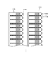
- FIG. 1 is a perspective view showing the configuration of the heat exchanger 100 according to the first embodiment.
- the heat exchanger 100 shown in FIG. 1 is provided in, for example, an outdoor unit of an air conditioner and operates as an evaporator or a condenser.
- the heat exchanger 100 includes a heat exchange core portion 110, an inlet header 120, an inflow pipe 130, an outlet header 140, an outflow pipe 150, and a folded header 170.
- the heat exchange core portion 110 has an L-shape in a plan view, and has two rows of heat transfer tubes stacked in multiple stages. Further, the heat exchange core portion 110 has a plurality of fins that guide air around the heat transfer tube and promote heat exchange with the refrigerant flowing in the heat transfer tube. Specifically, FIG. 2 is a diagram showing a cross section taken along line II of FIG. 1, and FIG. 3 is a diagram showing a cross section taken along line II-II of FIG. Note that in FIG. 1, detailed illustration of the heat transfer tube and fins of the heat exchange core portion 110 is omitted.
- the heat exchange core portion 110 has an inlet side heat transfer tube 111a, an inlet side fin 112a, an outlet side heat transfer tube 111b, and an outlet side fin 112b.
- the heat exchange core portion 110 has a row in which the inlet side heat transfer tubes 111a are laminated in multiple stages at intervals and a row in which the outlet side heat transfer tubes 111b are laminated in multiple stages at intervals, and the same row.
- the inlet side heat transfer tube 111a and the outlet side heat transfer tube 111b of the stage are arranged side by side so as to be close to each other and extend in parallel.
- the inlet side heat transfer tube 111a and the outlet side heat transfer tube 111b are flat tubes having a flat cross section, and the inlet side heat transfer tube 111a and the outlet side heat transfer tube 111b have the same cross-sectional shape.
- a plurality of flow paths of the refrigerant are arranged in the longitudinal direction.
- the inlet side heat transfer tube 111a extends from the inlet header 120 to the folded header 170, and the outlet side heat transfer tube 111b extends from the outlet header 140 to the folded header 170.
- the inlet side heat transfer tube 111a and the outlet side heat transfer tube 111b penetrate through the comb-shaped inlet side fin 112a and the outlet side fin 112b extending in the stacking direction of the inlet side heat transfer tube 111a and the outlet side heat transfer tube 111b. That is, for example, as shown in FIG. 3, the inlet side heat transfer tube 111a penetrates the plurality of inlet side fins 112a, and the refrigerant flowing inside the inlet side heat transfer tube 111a passes between the plurality of inlet side fins 112a. It is designed to efficiently exchange heat with and from.
- outlet-side heat transfer tube 111b penetrates the plurality of outlet-side fins 112b, and the refrigerant flowing inside the outlet-side heat transfer tube 111b efficiently interacts with the air passing between the plurality of outlet-side fins 112b. It is designed to exchange heat.
- the inlet side fin 112a and the outlet side fin 112b extend in the stacking direction of the inlet side heat transfer tube 111a and the outlet side heat transfer tube 111b, and between the comb-shaped teeth, the inlet side heat transfer tube 111a and the outlet side heat transfer tube 111b. And is inserted. That is, the inlet side fins 112a insert a plurality of inlet side heat transfer tubes 111a arranged in a row in the stacking direction, and the outlet side fins 112b insert a plurality of outlet side heat transfer tubes 111b arranged in a row in the stacking direction.
- the inlet header 120 and the outlet header 140 are provided at one end of the heat exchanger 100.
- the inlet header 120 is connected to a plurality of inlet side heat transfer tubes 111a arranged in a row in the stacking direction
- the outlet header 140 is connected to a plurality of outlet side heat transfer tubes 111b arranged in a row in the stacking direction.
- the inlet header 120 serves as an inlet header for the refrigerant when the heat exchanger 100 functions as an evaporator, and sends out the gas-liquid two-phase state refrigerant flowing from the inflow pipe 130 to the inlet side heat transfer pipe 111a. Further, the inlet header 120 serves as an outlet header of the refrigerant when the heat exchanger 100 functions as a condenser, and sends out the gas-liquid two-phase state refrigerant flowing from the inlet side heat transfer pipe 111a to the inflow pipe 130.
- the outlet header 140 serves as an outlet header for the refrigerant when the heat exchanger 100 functions as an evaporator, and the outflow pipe 150 discharges the refrigerant in the gas-liquid two-phase state or the gas-single-phase state flowing from the outlet-side heat transfer tube 111b. Send to. Further, the outlet header 140 serves as an inlet header for the refrigerant when the heat exchanger 100 functions as a condenser, and sends the air-single-phase refrigerant flowing from the outflow pipe 150 to the outlet side heat transfer pipe 111b.
- the folded header 170 is provided at an end opposite to one end where the inlet header 120 and the outlet header 140 of the heat exchanger 100 are provided, and connects the inlet side heat transfer tube 111a and the outlet side heat transfer tube 111b. That is, the folded header 170 has a space in which the tips of the pair of inlet side heat transfer tubes 111a and the outlet side heat transfer tubes 111b in the same stage are commonly connected, and the refrigerant flowing out from the tips of the inlet side heat transfer tubes 111a is discharged. The refrigerant flows back into the outlet side heat transfer tube 111b, and the refrigerant flowing out from the tip of the outlet side heat transfer tube 111b is folded back into the inlet side heat transfer tube 111a.
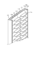
- FIG. 4 is a diagram showing the structure of the wrapping header 170.
- FIG. 4 is a perspective view of the folded header 170 as viewed from the side of the inlet side heat transfer tube 111a and the outlet side heat transfer tube 111b (that is, inside the heat exchanger 100).
- the folded header 170 is formed by joining two plate-shaped members 171 and 172, for example, by brazing.
- the end 171a of the plate-shaped member 171 in the row width direction (hereinafter, simply referred to as “row width direction”) in which the pair of inlet side heat transfer tubes 111a and the outlet side heat transfer tubes 111b in the same stage are lined up is the inlet side heat transfer tube.
- the end portion 172a of the plate-shaped member 172 in the row width direction is also bent toward the side of the inlet side heat transfer tube 111a and the outlet side heat transfer tube 111b.
- the joint portion between the end portion 171a of the plate-shaped member 171 and the end portion 172a of the plate-shaped member 172 forms a bent portion 170a of the folded header 170. That is, both ends of the joint portion of the two plate-shaped members 171 and 172 in the row width direction are bent portions 170a bent toward the plate-shaped member 172 side.
- a recess 171b for each step of the inlet side heat transfer tube 111a and the outlet side heat transfer tube 111b is formed in the center of the plate-shaped member 171, and the inlet side heat transfer tube 111a and the outlet side heat transfer tube 111b are formed in the center of the plate-shaped member 172.
- a recess 172b is formed for each step. Then, in the plate-shaped members 171 and 172, the recesses 171b and 172b corresponding to the same stage of the inlet side heat transfer tube 111a and the outlet side heat transfer tube 111b face each other so as to face each other, and a space is formed by the recesses 171b and 172b facing each other. It is joined so as to.
- the brazing material for joining the plate-shaped members 171 and 172 is contained in, for example, a clad layer formed on the surface of the plate-shaped member 172, and when the clad layer is heated, the brazing material is melted and plate-shaped.
- the member 171 and the plate-shaped member 172 are joined.
- the tips of the inlet side heat transfer tube 111a and the outlet side heat transfer tube 111b penetrate the bottom of the recess 172b, and the space formed by the recesses 171b and 172b connects the inlet side heat transfer tube 111a and the outlet side heat transfer tube 111b. That is, the refrigerant can be folded back between the inlet side heat transfer tube 111a and the outlet side heat transfer tube 111b through the space formed by the recesses 171b and 172b.
- the portions of the plate-shaped members 171 and 172 excluding the recesses 171b and 172b are joints that are joined to the plate-shaped members 172 and 171 facing each other by brazing, for example. That is, the portion of the plate-shaped member 171 excluding the recess 171b becomes a joint portion to be joined to the plate-shaped member 172 by brazing, for example, and the portion of the plate-shaped member 172 excluding the recess 172b is formed by brazing, for example, the plate-shaped member 171. It becomes a joint part to be joined to.
- the joint portions of the plate-shaped members 171 and 172 each have an area of a certain degree or more. That is, for example, the folded header 170 shown in FIG. 4 has a joint portion having a relatively large area on the side of the recesses 171b and 172b.
- the ends 171a and 172a of the joint portion in the row width direction are the bent portions 170a of the folded header 170 as described above.
- the bent portion 170a is bent so as to be substantially parallel to the extending direction of the inlet side heat transfer tube 111a and the outlet side heat transfer tube 111b penetrating the bottom of the recess 172b.
- the bent portion 170a is bent at a substantially right angle to the joint portion around the recesses 171b and 172b.
- the bent portion 170a By forming the bent portion 170a in this way, even when the area of the joint portion of the plate-shaped members 171 and 172 is increased to secure the joint strength, the size of the folded header 170 in the column width direction is reduced. be able to. As a result, the space occupied by the wrapping header 170 can be reduced to save space.
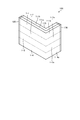
- FIG. 5 is a view showing a cross section of the folded header 170 in a plane perpendicular to the stacking direction (hereinafter, simply referred to as “stacking direction”) between the inlet side heat transfer tube 111a and the outlet side heat transfer tube 111b.
- the plate-shaped members 171 and 172 are joined so that the bottoms of the recess 171b of the plate-shaped member 171 and the recess 172b of the plate-shaped member 172 face each other so as to face each other.
- a space 170b is formed in which the heat tube 111a and the outlet side heat transfer tube 111b are connected.
- the tips of the inlet side heat transfer tube 111a and the outlet side heat transfer tube 111b penetrate the bottom of the recess 172b and reach the space 170b.
- the inlet side heat transfer tube 111a and the outlet side heat transfer tube 111b are connected by the space 170b.
- the portion excluding the recesses 171b and 172b is a joint portion for joining the plate-shaped members 171 and 172 by brazing, for example, and both ends of the joint portion in the row width direction are the inlet side heat transfer tube 111a and the outlet side heat transfer tube 111b.
- the bent portion 170a is bent in a direction substantially parallel to the extending direction. That is, the end portion 171a of the plate-shaped member 171 in the row width direction is bent toward the inlet side heat transfer tube 111a and the outlet side heat transfer tube 111b, and the end portion 172a of the plate-shaped member 172 in the row width direction is the inlet side transmission. It is bent toward the side of the heat tube 111a and the outlet side heat transfer tube 111b, and these end portions 171a and 172a are joined to form a bent portion 170a.
- FIG. 6 is a schematic view showing the heat exchanger 100.
- FIG. 7 is another schematic view showing the heat exchanger 100.
- the heat exchange core unit 110 includes a first heat exchange unit 1-1, a second heat exchange unit 1-2, a third heat exchange unit 1-3, and a fourth heat exchange unit 1-4.
- the first heat exchange unit 1-1, the second heat exchange unit 1-2, the third heat exchange unit 1-3, and the fourth heat exchange unit 1-4 are when the heat exchanger 100 is properly installed. In addition, they are lined up in the vertical direction.
- the first heat exchange unit 1-1 includes a plurality of first inlet-side heat transfer tubes 1-1a and a plurality of first outlet-side heat transfer tubes 1-1b.
- the plurality of first inlet-side heat transfer tubes 1-1a are included in the plurality of inlet-side heat transfer tubes 111a and are arranged in the vertical direction.
- the plurality of first outlet-side heat transfer tubes 1-1b are included in the plurality of outlet-side heat transfer tubes 111b and are arranged in the vertical direction.
- the second heat exchange section 1-2 is arranged adjacent to the lower side of the first heat exchange section 1-1, and has a plurality of second inlet side heat transfer tubes 1-2a and a plurality of second outlet side heat transfer tubes 1-2b. And have.
- the plurality of second inlet-side heat transfer tubes 1-2a are included in the plurality of inlet-side heat transfer tubes 111a and are arranged in the vertical direction.
- the plurality of second outlet-side heat transfer tubes 1-2b are included in the plurality of outlet-side heat transfer tubes 111b and are arranged in the vertical direction.
- the uppermost second inlet side heat transfer tube of the plurality of second inlet side heat transfer tubes 1-2a is the lowermost first inlet side heat transfer tube of the plurality of first inlet side heat transfer tubes 1-1a.
- the uppermost second outlet side heat transfer tube of the plurality of second outlet side heat transfer tubes 1-2b is the lowermost first outlet side heat transfer tube of the plurality of first outlet side heat transfer tubes 1-1b. It is located below.
- the second heat exchange section 1-2 includes a plurality of second inlet side heat transfer tubes 1-2a and a plurality of second outlet side heat transfer tubes 1-2b.
- the third heat exchange section 1-3 is arranged adjacent to the lower side of the second heat exchange section 1-2, and has a plurality of third inlet side heat transfer tubes 1-3a and a plurality of third outlet side heat transfer tubes 1-3b. And have.
- the plurality of third inlet-side heat transfer tubes 1-3a are included in the plurality of inlet-side heat transfer tubes 111a and are arranged in the vertical direction.
- the plurality of third outlet-side heat transfer tubes 1-3b are included in the plurality of outlet-side heat transfer tubes 111b and are arranged in the vertical direction.
- the uppermost third inlet side heat transfer tube of the plurality of third inlet side heat transfer tubes 1-3a is the lowermost second inlet side heat transfer tube of the plurality of second inlet side heat transfer tubes 1-2a.
- the third heat exchange unit 1-3 includes a plurality of third inlet side heat transfer tubes 1-3a and a plurality of third outlet side heat transfer tubes 1-3b.
- the fourth heat exchange section 1-4 is arranged adjacent to the lower part of the third heat exchange section 1-3, and has a plurality of fourth inlet side heat transfer tubes 1-4a and a plurality of fourth outlet side heat transfer tubes 1-4b. And have.
- the plurality of fourth inlet-side heat transfer tubes 1-4a are included in the plurality of inlet-side heat transfer tubes 111a and are arranged in the vertical direction.
- the plurality of fourth outlet-side heat transfer tubes 1-4b are included in the plurality of outlet-side heat transfer tubes 111b and are arranged in the vertical direction.
- the uppermost fourth inlet side heat transfer tube of the plurality of fourth inlet side heat transfer tubes 1-4a is the lowermost second inlet side heat transfer tube of the plurality of third inlet side heat transfer tubes 1-3a.
- the uppermost fourth outlet side heat transfer tube among the plurality of fourth outlet side heat transfer tubes 1-4b is the lowermost third outlet side heat transfer tube among the plurality of third outlet side heat transfer tubes 1-3b. It is located adjacent to the bottom.
- the fourth heat exchange section 1-4 includes a plurality of fourth inlet side heat transfer tubes 1-4a and a plurality of fourth outlet side heat transfer tubes 1-4b.
- the entrance header 120 is formed with a first entrance space 2-1, a second entrance space 2-2, a third entrance space 2-3, and a fourth entrance space 2-4.
- the first entrance space 2-1 and the second entrance space 2-2, the third entrance space 2-3, and the fourth entrance space 2-4 are isolated from each other.
- a plurality of first inlet side heat transfer tubes 1-1a of the first heat exchange section 1-1 are connected to the first inlet space 2-1. At this time, one ends of the plurality of first inlet-side heat transfer tubes 1-1a connected to the first inlet space 2-1 are arranged side by side in the vertical direction.
- the second entrance space 2-2 is arranged below the first entrance space 2-1.
- a plurality of second inlet side heat transfer tubes 1-2a of the second heat exchange section 1-2 are connected to the second inlet space 2-2.
- one ends of the plurality of second inlet side heat transfer tubes 1-2a connected to the second inlet space 2-2 are arranged side by side in the vertical direction.
- the third entrance space 2-3 is arranged below the second entrance space 2-2.
- a plurality of third inlet side heat transfer tubes 1-3a of the third heat exchange section 1-3 are connected to the third inlet space 2-3.
- one ends of the plurality of third inlet side heat transfer tubes 1-3a connected to the third inlet space 2-3 are arranged side by side in the vertical direction.
- the 4th entrance space 2-4 is arranged below the 3rd entrance space 2-3.
- a plurality of fourth inlet side heat transfer tubes 1-4a of the fourth heat exchange section 1-4 are connected to the fourth inlet space 2-4.
- one ends of the plurality of fourth inlet side heat transfer tubes 1-4a connected to the fourth inlet space 2-4 are arranged side by side in the vertical direction.
- the heat exchanger 100 further includes a shunt 3.
- the shunt 3 is provided in the first inlet space 2-1 and the second inlet space 2-2, the third inlet space 2-3, and the fourth inlet space 2-4 of the inlet header 120 via the plurality of inflow pipes 130. It is connected.
- the diversion device 3 the dryness of the gas-liquid two-phase refrigerant supplied to the first inlet space 2-1 and the second inlet space 2-2, the third inlet space 2-3, and the fourth inlet space 2-4, respectively. Is divided to the same level, and the gas-liquid two-phase refrigerant is supplied to the inlet header 120.
- An exit space 4 is formed in the exit header 140.
- a plurality of first outlet side heat transfer tubes 1-1b, a plurality of second outlet side heat transfer tubes 1-2b, a plurality of third outlet side heat transfer tubes 1-3b, and a plurality of fourth outlet side heat transfer tubes are provided in the outlet space 4.
- 1-4b is connected. That is, one ends of the plurality of outlet-side heat transfer tubes 111b are arranged in the outlet space 4.
- the folded header 170 includes an inlet header 120 and an outlet header 140 of the first heat exchange section 1-1, the second heat exchange section 1-2, the third heat exchange section 1-3, and the fourth heat exchange section 1-4. It is connected to the other end on the opposite side of one end connected to.
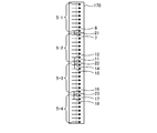
- FIG. 8 is a schematic view showing the wrapping header 170.
- the wrapping header 170 is formed with a plurality of wrapping spaces represented by arrows pointing to the right in FIG.
- Each of the plurality of folded spaces is formed in the same manner as the space 170b, and the plurality of folded spaces are isolated from each other.
- the total number of the plurality of folded spaces is the same as the total number of the inlet side heat transfer tubes 111a, and is the same as the total number of the outlet side heat transfer tubes 111b.
- the plurality of folding spaces include a plurality of first folding spaces 5-1 and a plurality of second folding spaces 5-2, a plurality of third folding spaces 5-3, and a plurality of fourth folding spaces 5-4. ..
- the plurality of first folded spaces 5-1 are each connected to a plurality of first inlet side heat transfer tubes 1-1a, and are connected to a plurality of first outlet side heat transfer tubes 1-1b, respectively. That is, each of the plurality of first folded spaces 5-1 is connected to one of the plurality of first inlet side heat transfer tubes 1-1a on the first inlet side heat transfer tube, and the plurality of first outlet side heat transfer tubes 1 It is connected to the first outlet side heat transfer tube of one of -1b.
- the plurality of first folded spaces 5-1 include the first folded space 6 at the bottom (bottom side).
- the lowermost first folded space 6 is connected to the lowermost first inlet side heat transfer tube among the plurality of first inlet side heat transfer tubes 1-1a.
- the lowermost first inlet side heat transfer tube is a flow path arranged at the lowermost side of the plurality of first inlet side heat transfer tubes 1-1a, and is among the lowermost first inlet side heat transfer tubes.
- One end of the side connected to the first entrance space 2-1 is connected to the lowermost portion of the first entrance space 2-1.
- one end of the other first inlet side heat transfer tube different from the lowermost first inlet side heat transfer tube 1-1a of the plurality of first inlet side heat transfer tubes 1-1a is in the first inlet space 2-1. It is arranged in a portion above the portion where one end of the lowermost first inlet side heat transfer tube is arranged.
- the plurality of second folded spaces 5-2 are connected to a plurality of second inlet side heat transfer tubes 1-2a, respectively, and are connected to a plurality of second outlet side heat transfer tubes 1-2b, respectively. That is, each of the plurality of second folded spaces 5-2 is connected to one of the plurality of second inlet side heat transfer tubes 1-2a, the second inlet side heat transfer tube, and the plurality of second outlet side heat transfer tubes 1
- the second of -2b is connected to the oral heat transfer tube.
- the plurality of second folded spaces 5-2 include the uppermost (topmost side) second folded space 7.
- the uppermost second folded space 7 is connected to the uppermost second inlet side heat transfer tube of the plurality of second inlet side heat transfer tubes 1-2a.
- the uppermost second inlet side heat transfer tube is a flow path arranged on the uppermost side of the plurality of second inlet side heat transfer tubes 1-2a, and is among the uppermost second inlet side heat transfer tubes.
- One end on the side connected to the second entrance space 2-2 is connected to the uppermost portion of the second entrance space 2-2. That is, one end of the other second inlet side heat transfer tube different from the uppermost second inlet side heat transfer tube 1-2a of the plurality of second inlet side heat transfer tubes 1-2a is in the second inlet space 2-2. It is arranged in a portion above the portion where one end of the uppermost second inlet side heat transfer tube is arranged.
- the plurality of second folded spaces 5-2 further include a second lower folded space 11 and a second lower second folded space 12.
- the lowermost second folded space 11 is connected to the lowermost second inlet side heat transfer tube of the plurality of second inlet side heat transfer tubes 1-2a.
- the lowermost second inlet side heat transfer tube is a flow path arranged at the lowermost side of the plurality of second inlet side heat transfer tubes 1-2a, and is among the lowermost second inlet side heat transfer tubes.
- One end of the side connected to the second entrance space 2-2 is connected to the lowermost part of the second entrance space 2-2.
- the second lower second folded space 12 is connected to the second lower second inlet side heat transfer tube of the plurality of second inlet side heat transfer tubes 1-2a.
- the second lower second inlet side heat transfer tube is a flow path arranged on the second lower side of the plurality of second inlet side heat transfer tubes 1-2a.
- One end of the second lower second inlet side heat transfer tube connected to the second inlet space 2-2 is the second lower inlet space 2-after one end of the lower second inlet side heat transfer tube. It is connected to the second lower part of 2.
- the plurality of third folded spaces 5-3 are connected to a plurality of third inlet side heat transfer tubes 1-3a, respectively, and are connected to a plurality of third outlet side heat transfer tubes 1-3b, respectively. That is, each of the plurality of third folded spaces 5-3 is connected to one of the plurality of third inlet side heat transfer tubes 1-3a on the third inlet side heat transfer tube, and the plurality of third outlet side heat transfer tubes 1
- the third of -3b is connected to the oral heat transfer tube.
- the plurality of third folded spaces 5-3 include the first upper third folded space 14 and the second upper third folded space 15.
- the uppermost third folded space 14 is connected to the uppermost third inlet side heat transfer tube among the plurality of third inlet side heat transfer tubes 1-3a.
- the uppermost third inlet side heat transfer tube is a flow path arranged on the uppermost side of the plurality of third inlet side heat transfer tubes 1-3a, and is among the uppermost third inlet side heat transfer tubes.
- One end on the side connected to the third entrance space 2-3 is connected to the uppermost portion of the third entrance space 2-3. That is, one end of the other third inlet side heat transfer tube different from the uppermost third inlet side heat transfer tube of the plurality of third inlet side heat transfer tubes 1-3a is in the third inlet space 2-3. It is arranged in a portion below the portion where one end of the uppermost third inlet side heat transfer tube is arranged.
- the second upper third folded space 15 is connected to the second upper third inlet side heat transfer tube among the plurality of third inlet side heat transfer tubes 1-3a.
- the second upper third inlet side heat transfer tube is a flow path arranged second upper after the uppermost third inlet side heat transfer tube among the plurality of third inlet side heat transfer tubes 1-3a. be.
- One end of the second upper third inlet side heat transfer tube connected to the third inlet space 2-3 is the second upper part after one end of the first upper third inlet side heat transfer tube. It is connected to the.
- the plurality of third folded spaces 5-3 further include the lowermost third folded space 16.
- the lowermost third folded space 16 is connected to the lowermost third inlet side heat transfer tube among the plurality of third inlet side heat transfer tubes 1-3a.
- the lowermost third inlet side heat transfer tube is a flow path arranged at the lowermost side of the plurality of third inlet side heat transfer tubes 1-3a, and is among the lowermost third inlet side heat transfer tubes.
- One end of the side connected to the third entrance space 2-3 is connected to the lowermost part of the third entrance space 2-3. That is, one end of the other third inlet side heat transfer tube different from the uppermost third inlet side heat transfer tube of the plurality of third inlet side heat transfer tubes 1-3a is in the third inlet space 2-3. It is arranged in a portion below the portion where one end of the uppermost third inlet side heat transfer tube is arranged.
- the plurality of fourth folded spaces 5-4 are connected to a plurality of fourth inlet side heat transfer tubes 1-4a, respectively, and are connected to a plurality of fourth outlet side heat transfer tubes 1-4b, respectively. That is, each of the plurality of fourth folded spaces 5-4 is connected to the fourth inlet side heat transfer tube of one of the plurality of fourth inlet side heat transfer tubes 1-4a, and the plurality of fourth outlet side heat transfer tubes 1
- the fourth of -4b is connected to the oral heat transfer tube.
- the plurality of fourth folded spaces 5-4 include the first upper fourth folded space 17 and the second upper fourth folded space 18.
- the uppermost fourth folded-back space 17 is connected to the uppermost fourth inlet side heat transfer tube among the plurality of fourth inlet side heat transfer tubes 1-4a.
- the uppermost fourth inlet side heat transfer tube is a flow path arranged on the uppermost side of the plurality of fourth inlet side heat transfer tubes 1-4a, and is among the uppermost fourth inlet side heat transfer tubes.
- One end on the side connected to the fourth entrance space 2-4 is connected to the uppermost portion of the fourth entrance space 2-4. That is, one end of the other 4th inlet side heat transfer tube different from the uppermost 4th inlet side heat transfer tube among the plurality of 4th inlet side heat transfer tubes 1-4a is in the 4th inlet space 2-4. It is arranged in a portion below the portion where one end of the uppermost fourth inlet side heat transfer tube is arranged.
- the second upper fourth folded space 18 is connected to the second upper fourth inlet side heat transfer tube among the plurality of fourth inlet side heat transfer tubes 1-4a.
- the second upper fourth inlet side heat transfer tube is a flow path arranged second upper after the uppermost fourth inlet side heat transfer tube among the plurality of fourth inlet side heat transfer tubes 1-4a. be.
- One end of the second upper fourth inlet side heat transfer tube connected to the fourth inlet space 2-4 is the second upper part after one end of the first upper fourth inlet side heat transfer tube. It is connected to the.
- the folded header 170 is further provided with a first refrigerant pipe 21, a second refrigerant pipe 22, and a third refrigerant pipe 23.
- a first continuous passage is formed inside the first refrigerant pipe 21.
- the first continuous passage communicates with the lowermost first folding space 6 of the plurality of first folding spaces 5-1 and is the uppermost second folding of the plurality of second folding spaces 5-2. It communicates with space 7.
- a second continuous passage is formed inside the second refrigerant pipe 22.
- the second passage communicates with the lowermost second folding space 11 and the second lower second folding space 12 of the plurality of second folding spaces 5-2, and the plurality of third folding spaces 5 It communicates with the uppermost third folding space 14 of -3 and the second upper third folding space 15.
- a third continuous passage is formed inside the third refrigerant pipe 23.
- the third passage communicates with the lowermost third folding space 16 of the plurality of third folding spaces 5-3, and the uppermost fourth folding of the plurality of fourth folding spaces 5-4. It communicates with the space 17 and the second upper fourth folded space 18.
- the heat exchanger 100 operates as an evaporator or a condenser.
- the diversion device 3 transfers the inflowing refrigerant into the first inlet space 2-1 and the second inlet space 2-2, the third inlet space 2-3, and the fourth inlet space 2- of the inlet header 120.
- the gas-liquid two-phase refrigerant supplied to each of No. 4 is split so as to have the same degree of dryness.
- the gas-liquid two-phase refrigerant supplied to the first inlet space 2-1 is supplied to the plurality of first inlet side heat transfer tubes 1-1a and flows through the plurality of first inlet side heat transfer tubes 1-1a. At this time, the dryness of the gas-liquid two-phase refrigerant supplied to the plurality of first inlet-side heat transfer tubes 1-1a is larger than that of the first inlet-side heat transfer tubes arranged on the upper side.
- the gas-liquid two-phase refrigerant supplied to each of the second inlet space 2-2, the third inlet space 2-3, and the fourth inlet space 2-4 is also the gas-liquid two-phase refrigerant in the first inlet space 2-1.
- the dryness of the upper gas-liquid two-phase refrigerant is greater than the dryness of the lower gas-liquid two-phase refrigerant.
- the gas-liquid two-phase refrigerant supplied to each of the second inlet space 2-2, the third inlet space 2-3, and the fourth inlet space 2-4 is a plurality of second inlet side heat transfer tubes 1-2a. It is supplied to the third inlet side heat transfer tube 1-3a and the plurality of fourth inlet side heat transfer tubes 1-4a, respectively.
- the dryness of the gas-liquid two-phase refrigerant supplied to the plurality of second inlet-side heat transfer tubes 1-2a is the same as that of the gas-liquid two-phase refrigerant supplied to the plurality of first inlet-side heat transfer tubes 1-1a.
- the heat transfer tube on the second inlet side arranged on the upper side is larger.
- the dryness of the gas-liquid two-phase refrigerant supplied to the plurality of third inlet side heat transfer tubes 1-3a is larger than that of the third inlet side heat transfer tubes arranged on the upper side, and the plurality of fourth inlet side heat transfer tubes are provided.
- the dryness of the gas-liquid two-phase refrigerant supplied to 1-4a is larger as the heat transfer tube on the fourth inlet side is arranged on the upper side.
- the air flowing outside the plurality of inlet-side heat transfer tubes 111a and the gas-liquid two-phase refrigerant flowing through the plurality of inlet-side heat transfer tubes 111a are in thermal contact with the plurality of inlet-side heat transfer tubes 111a, so that the plurality of inlet-side heat transfer tubes 111a are in contact with each other. Heat is exchanged with each other via the inlet side heat transfer tube 111a. That is, the air flowing outside the plurality of inlet-side heat transfer tubes 111a is cooled by such heat exchange.
- the gas-liquid two-phase refrigerant flowing through the plurality of inlet-side heat transfer tubes 111a has a plurality of first folded spaces 5-1 of the folded header 170, a plurality of second folded spaces 5-2, and a plurality of third folded spaces 5-3. And a plurality of fourth folded spaces 5-4.
- the gas-liquid two-phase refrigerant flowing through the first inlet-side heat transfer tube among the plurality of first inlet-side heat transfer tubes 1-1a is the first of the plurality of first folded spaces 5-1. It is supplied to the first folded space connected to the inlet side heat transfer tube.
- the gas-liquid two-phase refrigerant flowing through the lowermost first inlet-side heat transfer tube 1-1a of the plurality of first inlet-side heat transfer tubes 1-1a is the first of the plurality of first folded spaces 5-1. It is supplied to the lower first folded space 6.
- the gas-liquid two-phase refrigerant flowing through the plurality of second inlet-side heat transfer tubes 1-2a is the same as the gas-liquid two-phase refrigerant flowing through the plurality of first inlet-side heat transfer tubes 1-1a. It is supplied to the second folding space 5-2, respectively.
- the gas-liquid two-phase refrigerant flowing through the uppermost second inlet side heat transfer tube 1-2a of the plurality of second inlet side heat transfer tubes 1-2a is the first of the plurality of second folded spaces 5-2. It is supplied to the upper second folded space 7.
- the gas-liquid two-phase refrigerant flowing through the second inlet side heat transfer tube at the bottom of the plurality of second inlet side heat transfer tubes 1-2a is at the bottom of the plurality of second folded spaces 5-2. It is supplied to the second folded space 11.
- the gas-liquid two-phase refrigerant that has flowed through the second lower second inlet side heat transfer tube 1-2a, which is the second of the plurality of second inlet side heat transfer tubes 1-2a, is the second of the plurality of second folded spaces 5-2. It is supplied to the lower second folded space 12.
- the gas-liquid two-phase refrigerant that has flowed through the plurality of third inlet side heat transfer tubes 1-3a is supplied to each of the plurality of third folded spaces 5-3 of the folded header 170.
- the gas-liquid two-phase refrigerant flowing through the uppermost third inlet side heat transfer tube 1-3a among the plurality of third inlet side heat transfer tubes 1-3a is the first of the plurality of third folded spaces 5-3. It is supplied to the upper third folded space 14.
- the gas-liquid two-phase refrigerant that has flowed through the second upper third inlet side heat transfer tube 1-3a among the plurality of third inlet side heat transfer tubes 1-3a is the second of the plurality of third folded spaces 5-3. It is supplied to the upper third folded space 15.
- the gas-liquid two-phase refrigerant flowing through the third inlet side heat transfer tube at the bottom of the plurality of third inlet side heat transfer tubes 1-3a is at the bottom of the plurality of third folded spaces 5-3. It is supplied to the third folded space
- the gas-liquid two-phase refrigerant that has flowed through the plurality of fourth inlet-side heat transfer tubes 1-4a is supplied to the plurality of fourth folded spaces 5-4 of the folded header 170, respectively.
- the gas-liquid two-phase refrigerant flowing through the uppermost fourth inlet side heat transfer tube 1-4a among the plurality of fourth inlet side heat transfer tubes 1-4a is the first of the plurality of fourth folded spaces 5-4. It is supplied to the upper fourth folded space 17.
- the gas-liquid two-phase refrigerant that has flowed through the fourth upper inlet side heat transfer tube 1-4a, which is the second of the plurality of fourth inlet side heat transfer tubes 1-4a, is the second of the plurality of fourth folded spaces 5-4. It is supplied to the upper fourth folded space 18.
- the gas-liquid two-phase refrigerant supplied to the uppermost (topmost side) second folding space 7 is the lowermost first folding space 6 and the plurality of second of the plurality of first folding spaces 5-1.
- the second folded space 7 at the top of the folded space 5-2 is communicated with the first refrigerant pipe 21 to be mixed.
- the mixed gas-liquid two-phase refrigerant is connected to a plurality of first fold-out spaces 5-1 from the lowermost first fold-back space 6 of the plurality of first fold-back spaces 5-1.
- the lowermost second folding space 11 of the plurality of second folding spaces 5-2, the second lower second folding space 12, and one of the plurality of third folding spaces 5-3 is mixed by the second refrigerant pipe 22.
- the gas-liquid two-phase refrigerant mixed by the second refrigerant pipe 22 is the lowermost second outlet side heat transfer pipe connected to the plurality of second folded spaces 5-2 and the second lower second outlet side heat transfer pipe. It is supplied to the first upper third outlet side heat transfer tube and the second upper third outlet side heat transfer tube connected to the heat tube and the plurality of third folded spaces 5-3.
- the gas-liquid two-phase refrigerant supplied to each of the four folded spaces 18 is mixed by the third refrigerant pipe 23.
- the gas-liquid two-phase refrigerant mixed by the third refrigerant pipe 23 is connected to the lowermost third outlet side heat transfer pipe and the plurality of fourth folded spaces 5-4 connected to the plurality of third folded spaces 5-3. It is supplied to the first upper fourth outlet side heat transfer tube and the second upper fourth outlet side heat transfer tube connected.
- the gas-liquid two-phase refrigerant supplied to a certain first folding space different from the lowermost first folding space 6 of the plurality of first folding spaces 5-1 is not mixed with other gas-liquid two-phase refrigerants. As it is, it is supplied to the first outlet side heat transfer tube connected to the first folding space of the plurality of first outlet side heat transfer tubes 1-1b. In a second folding space that is different from the second folding space 7 at the top of the plurality of second folding spaces 5-2, the second folding space 11 at the bottom, and the second folding space 12 at the bottom.
- the supplied gas-liquid two-phase refrigerant is also supplied as it is to the second outlet side heat transfer tube connected to the second folding space of the plurality of second outlet side heat transfer tubes 1-2b.
- the second upper third folding space 15 and the lowermost third folding space 16 The supplied gas-liquid two-phase refrigerant is also supplied as it is to the third outlet side heat transfer tube connected to the third folded space of the plurality of third outlet side heat transfer tubes 1-3b.
- the gas-liquid two-phase refrigerant supplied to a certain fourth folding space different from the uppermost fourth folding space 17 and the second upper fourth folding space 18 among the plurality of fourth folding spaces 5-4 also As it is, it is supplied to the fourth outlet side heat transfer tube connected to the fourth folded space of the plurality of fourth outlet side heat transfer tubes 1-4b.
- the air flowing outside the plurality of outlet-side heat transfer tubes 111b and the gas-liquid two-phase refrigerant flowing through the plurality of outlet-side heat transfer tubes 111b are in thermal contact with the plurality of inlet-side heat transfer tubes 111a, so that a plurality of gas-liquid two-phase refrigerants are in contact with each other. Heat is exchanged with each other via the inlet side heat transfer tube 111a. The air flowing outside the plurality of outlet-side heat transfer tubes 111b is cooled by such heat exchange.
- gas-liquid two-phase refrigerant flowing through the plurality of outlet-side heat transfer tubes 111b a part of the liquid-phase refrigerant of the gas-liquid two-phase refrigerant evaporates due to such heat exchange, and the dryness is further increased.
- the gas-liquid two-phase refrigerant that has flowed through the plurality of outlet-side heat transfer pipes 111b is supplied to the outlet header 140 and flows out to the outside through the outlet space 4 and the outflow pipe 150.
- Refrigerant with a high gas phase ratio can vaporize a small amount of refrigerant, so the amount of latent heat that contributes to heat exchange with air is small. That is, if the ratio of the gas phase and the liquid phase is not uniformly divided, the heat exchange capacity of the outlet side heat transfer tube 111b through which the highly dry refrigerant flows decreases, and the amount of heat exchange as a heat exchanger decreases. Invite. If the gas-liquid two-phase refrigerant supplied to the outlet-side heat transfer tube 111b has a high degree of dryness, the amount of heat exchange with air will decrease as compared with the case where the degree of dryness is low.
- the heat exchanger 100 of the present embodiment is provided with the first refrigerant pipe 21, the second refrigerant pipe 22, and the third refrigerant pipe 23, so that the heat exchanger 100 is dried after flowing through the plurality of inlet-side heat transfer pipes 111a.
- a gas-liquid two-phase refrigerant having a relatively small degree for example, a refrigerant in the uppermost second folded space 7 of a plurality of second folded spaces 5-2
- a gas-liquid two-phase refrigerant having a relatively large degree of dryness for example, the refrigerant in the lowermost first folded space 6 of the plurality of first folded spaces 5-1) can be mixed.
- the heat exchanger 100 can supply the gas-liquid two-phase refrigerant having a uniform dryness to the plurality of outlet-side heat transfer tubes 111b by mixing the gas-liquid two-phase refrigerants having different dryness.
- the gas-liquid two-phase refrigerant having a uniform dryness flows through the plurality of outlet-side heat transfer tubes 111b, respectively, to the outlet-side heat transfer tube 111b in a state where the ratio of the gas phase and the liquid phase is uniform. Since the flow is divided, it is possible to suppress a decrease in the amount of heat exchange as a heat exchanger. Further, the air flowing outside the outlet side heat transfer tube 111b can be appropriately cooled.
- the refrigerant flows in the opposite direction to the operation as an evaporator. That is, in the heat exchanger 100, first, a gas-single-phase refrigerant or a gas-liquid two-phase refrigerant having a sufficiently high dryness is supplied to the outlet space 4 of the outlet header 140.
- the refrigerant supplied to the outlet space 4 is supplied to the plurality of outlet side heat transfer tubes 111b and flows through the plurality of outlet side heat transfer tubes 111b.
- the refrigerant supplied to the outlet space 4 has a sufficiently high dryness, so that the dryness is less likely to be biased by gravity. Therefore, the dryness of the refrigerants supplied to the plurality of outlet-side heat transfer tubes 111b are substantially the same.
- the air flowing outside the plurality of outlet side heat transfer tubes 111b and the refrigerant flowing through the plurality of outlet side heat transfer tubes 111b are in thermal contact with the plurality of outlet side heat transfer tubes 111b, so that the plurality of outlet side heat transfer tubes are in thermal contact with each other. Heat is exchanged with each other via 111b. A part of the refrigerant flowing through the plurality of outlet-side heat transfer tubes 111b is condensed by such heat exchange, and the dryness is lowered. The air flowing outside the plurality of outlet-side heat transfer tubes 111b is heated by such heat exchange.
- the refrigerant that has flowed through the plurality of outlet-side heat transfer tubes 111b is supplied to the folded header 170, and is supplied to each of the plurality of spaces formed in the folded header 170.
- the refrigerant supplied to the space 7 is the lowermost first folded space 6 of the plurality of first folded spaces 5-1 and the uppermost second of the plurality of second folded spaces 5-2.
- the folded space 7 is communicated with the first refrigerant pipe 21 to be mixed.
- the refrigerants supplied to the upper third turn-back space 14 and the second upper third turn-back space 15 are mixed by the second refrigerant pipe 22.
- the refrigerants supplied to the four folding spaces 18 are mixed by the third refrigerant pipe 23. Even when the refrigerants supplied to the plurality of spaces are mixed in this way, the dryness is substantially equal to each other because the dryness is originally substantially equal.
- the refrigerant supplied to each of the plurality of spaces is supplied to the plurality of inlet side heat transfer tubes 111a and flows through the plurality of inlet side heat transfer tubes 111a.
- the refrigerant flowing through the plurality of inlet side heat transfer tubes 111a and the air flowing outside the plurality of inlet side heat transfer tubes 111a are in thermal contact with the plurality of inlet side heat transfer tubes 111a, so that the plurality of inlet side heat transfer tubes are in thermal contact with each other.
- Heat is exchanged with each other via 111a.
- the refrigerant flowing through the plurality of inlet-side heat transfer tubes 111a is further condensed by such heat exchange, and the dryness is further lowered.
- the air flowing outside the plurality of inlet-side heat transfer tubes 111a is heated by such heat exchange.
- the gas-liquid two-phase refrigerant flowing through the plurality of inlet-side heat transfer tubes 111a is the first inlet space 2-1 and the second inlet space 2-2, the third inlet space 2-3, and the fourth inlet space 2 of the inlet header 120. It is supplied to the diversion device 3 via -4 and the inflow pipe 130, and flows out from the diversion device 3 to the outside.
- the dryness of the refrigerant is high even when the folded header 170 is provided with the first refrigerant pipe 21, the second refrigerant pipe 22, and the third refrigerant pipe 23. Can be properly lowered and can be properly operated as a condenser.
- the heat exchanger 100 of the first embodiment includes an inlet header 120, a plurality of inlet side heat transfer tubes 111a, a plurality of outlet side heat transfer tubes 111b, and a folded header 170. Inside the entrance header 120, a first entrance space 2-1 and a second entrance space 2-2 are formed.
- the plurality of inlet-side heat transfer tubes 111a include a plurality of first inlet-side heat transfer tubes 1-1a connected to the first inlet space 2-1 and a plurality of second inlet-sides connected to the second inlet space 2-2. Includes heat transfer tubes 1-2a.
- the plurality of outlet-side heat transfer tubes 111b include a plurality of first outlet-side heat transfer tubes 1-1b and a plurality of second outlet-side heat transfer tubes 1-2b.
- the folded header 170 includes a plurality of first folded spaces 5-1 for communicating the plurality of first inlet side heat transfer tubes 1-1a with the plurality of first outlet side heat transfer tubes 1-1b, and a plurality of second inlet sides.
- a plurality of second folded spaces 5-2 are formed in which the heat transfer tubes 1-2a are communicated with the plurality of second outlet side heat transfer tubes 1-2b, respectively.
- the lowermost first folded space 6 of the plurality of first folded spaces 5-1 is the lowest first folded space 6 arranged at the lowermost side of the plurality of first inlet side heat transfer tubes 1-1a.
- the uppermost second folded space 7 of the plurality of second folded spaces 5-2 is the uppermost second inlet arranged at the uppermost side of the plurality of second inlet side heat transfer tubes 1-2a. It is connected to the side heat transfer tube.
- the folded header 170 is further formed with a first refrigerant pipe 21 that communicates the lowermost first folded space 6 and the uppermost second folded space 7.
- the heat exchanger 100 of the first embodiment further includes a shunt 3 that supplies a gas-liquid two-phase state refrigerant to the first inlet space 2-1 and the second inlet space 2-2.
- a shunt 3 that supplies a gas-liquid two-phase state refrigerant to the first inlet space 2-1 and the second inlet space 2-2.
- the heat exchanger 100 is as dry as the upper first inlet side heat transfer tube. Refrigerant is supplied, and the higher the second inlet side heat transfer tube is, the more dry the refrigerant is supplied. Therefore, the dryness of the refrigerant flowing through the uppermost second inlet side heat transfer tube may be larger than the dryness of the refrigerant flowing through the lowermost first inlet side heat transfer tube.
- the heat exchanger 100 is provided with the first refrigerant pipe 21, the refrigerant that has flowed through the uppermost second inlet side heat transfer tube and the refrigerant that has flowed through the lowermost first inlet side heat transfer tube. Can be mixed, and a gas-liquid two-phase refrigerant having a uniform dryness can be supplied to a plurality of outlet-side heat transfer tubes 111b.
- the heat exchanger 100 can suppress a decrease in the amount of heat exchange as a heat exchanger by allowing the gas-liquid two-phase refrigerant having a uniform dryness to flow through the plurality of outlet-side heat transfer tubes 111b, respectively.
- the heat exchanger 100 of the first embodiment described above includes the shunt 3, but the shunt 3 may be omitted. Even if the shunt 3 is omitted, the heat exchanger 100 is diverted to the outlet side heat transfer tube in a state where the ratio of the gas phase and the liquid phase is uniform, so that the decrease in the amount of heat exchange as the heat exchanger is suppressed. can.
- the first refrigerant pipe 21 of the heat exchanger 100 of the first embodiment described above mixes the refrigerants supplied to the two spaces formed in the folded header 170, but the second refrigerant pipe 22 and the second refrigerant pipe 21 are mixed. 3 Refrigerants supplied to three or more spaces may be mixed, such as the refrigerant pipe 23. Also in this case, since the heat exchanger 100 is diverted to the outlet side heat transfer tube in a state where the ratio of the gas phase and the liquid phase is uniform, it is possible to suppress a decrease in the amount of heat exchange as the heat exchanger.
- the number of inlet-side heat transfer tubes connected to the first inlet space 2-1 of the plurality of inlet-side heat transfer tubes 111a of the heat exchanger 100 of the first embodiment is the second inlet space 2-2 and the third. It is less than the number of inlet side heat transfer tubes connected to each of the inlet space 2-3 and the fourth inlet space 2-4. Therefore, the length of the first entrance space 2-1 in the vertical direction may be shorter than that of the second entrance space 2-2, the third entrance space 2-3, and the fourth entrance space 2-4. can.
- the uppermost first inlet space 2-1 is an inlet space having the highest gas phase ratio, and the non-uniformity of the dryness of the refrigerant is relatively likely to occur due to the influence of gravity.
- the unevenness of the dryness of the refrigerant inside the first inlet space 2-1 is reduced, and the first inlet space 2-1 is connected to the first inlet space 2-1. It is possible to reduce the unevenness of the dryness of the gas-liquid two-phase refrigerant supplied to the plurality of first inlet-side heat transfer tubes 1-1a.
- the plurality of outlet-side heat transfer tubes 111b of the heat exchanger 100 of the first embodiment described above are arranged along the plurality of inlet-side heat transfer tubes 111a, but are arranged along the plurality of inlet-side heat transfer tubes 111a. It does not have to be.
- FIG. 9 is a schematic view showing the heat exchanger 200 of the second embodiment.
- the heat exchange core portion 110 of the heat exchanger 100 of the first embodiment described above is replaced with a plurality of inlet side core portions 210 and a plurality of outlet side core portions 220.
- the plurality of inlet-side core portions 210 are formed of the plurality of inlet-side heat transfer tubes 111a and the plurality of inlet-side fins 112a described above.
- the plurality of outlet-side core portions 220 are formed of the plurality of outlet-side heat transfer tubes 111b and the plurality of outlet-side fins 112b described above.
- the plurality of outlet-side core portions 220 are arranged so as to be along another plane perpendicular to the plane along which the plurality of inlet-side core portions 210 are aligned, and not along the plurality of inlet-side core portions 210.
- the folded header 170 of the heat exchanger 100 of the first embodiment described above is further replaced with another header 230.
- the header 230 has a plurality of first wrapping spaces 5-1 and a plurality of second wrapping spaces 5-2, a plurality of third wrapping spaces 5-3, and a plurality of fourth wrapping spaces 5 as in the above-described wrapping header 170. -4 and are formed.
- a refrigerant pipe 23 is provided.
- the heat exchanger 200 operates in the same manner as the heat exchanger 100 of the first embodiment described above.
- the ratio of the gas phase to the liquid phase is similar to that of the heat exchanger 100 of the first embodiment described above. Since the heat is diverted to the heat transfer tube on the outlet side in a uniform state, it is possible to suppress a decrease in the amount of heat exchange as a heat exchanger.
- the first continuous passage is formed by providing the first refrigerant pipe 21, but the first continuous passage is formed without using the first refrigerant pipe 21. May be good.
- the plate-shaped member 171 and the plate-shaped member 172 are formed with recesses, so that the lowermost first folded space 6 and the uppermost second folded space 7 are communicated with each other. A single passage may be formed.
- the wrapping header 170 includes a second wrapping space 11 at the bottom, a second wrapping space 12 at the bottom, a third wrapping space 14 at the top, and a third wrapping space 15 at the top.
- the second connecting passage may be formed by the recesses of the plate-shaped member 171 and the plate-shaped member 172.
- the third continuous passage connecting the lowermost third folded space 16 and the uppermost fourth folded space 17 and the second upper fourth folded space 18 is a plate-shaped member. It may be formed by a recess of 171 and a plate-shaped member 172.
- the heat exchanger can similarly suppress a decrease in the amount of heat exchange even when such a folded header is provided.
- Heat exchanger 110 Heat exchange core part 111a: Inlet side heat transfer tube 111b: Outlet side heat transfer tube 112a: Inlet side fin 112b: Outlet side fin 120: Inlet header 130: Inflow tube 140: Outlet header 150: Outflow tube 170 : Folded header 1-1: 1st heat exchange part 1-2: 2nd heat exchange part 1-3: 3rd heat exchange part 1-4: 4th heat exchange part 2-1: 1st inlet space 2-2 : 2nd entrance space 2-3: 3rd entrance space 2-4: 4th entrance space 3: Divider 5-1: Multiple 1st turn-back spaces 5-2: Multiple 2nd turn-back spaces 5-3: Multiple 3rd folding space 5-4: Multiple 4th folding space 6: 1st folding space at the bottom 7: 2nd folding space at the top 11: 2nd folding space at the bottom 12: 2nd Lower 2nd folding space 14: 1st upper 3rd folding space 15: 2nd upper 3rd folding space 16: 1st lower 3rd folding space 17: 1st upper 4
Landscapes
- Engineering & Computer Science (AREA)
- Physics & Mathematics (AREA)
- Thermal Sciences (AREA)
- Mechanical Engineering (AREA)
- General Engineering & Computer Science (AREA)
- Geometry (AREA)
- Heat-Exchange Devices With Radiators And Conduit Assemblies (AREA)
- Power Steering Mechanism (AREA)
- Compression-Type Refrigeration Machines With Reversible Cycles (AREA)
- Separation By Low-Temperature Treatments (AREA)
Abstract
Description
熱交換器100は、蒸発器または凝縮器として動作する。蒸発器としての動作では、分流器3は、流入した冷媒を入口ヘッダ120の第1入口空間2-1と第2入口空間2-2と第3入口空間2-3と第4入口空間2-4とのそれぞれに供給される気液二相冷媒の乾き度が同程度になるように分流する。
実施例1の熱交換器100は、入口ヘッダ120と複数の入口側伝熱管111aと複数の出口側伝熱管111bと折り返しヘッダ170とを備えている。入口ヘッダ120の内部には、第1入口空間2-1と第2入口空間2-2とが形成されている。複数の入口側伝熱管111aは、第1入口空間2-1に接続される複数の第1入口側伝熱管1-1aと、第2入口空間2-2に接続される複数の第2入口側伝熱管1-2aとを含んでいる。複数の出口側伝熱管111bは、複数の第1出口側伝熱管1-1bと複数の第2出口側伝熱管1-2bとを含んでいる。折り返しヘッダ170には、複数の第1入口側伝熱管1-1aを複数の第1出口側伝熱管1-1bにそれぞれ連通させる複数の第1折り返し空間5-1と、複数の第2入口側伝熱管1-2aを複数の第2出口側伝熱管1-2bにそれぞれ連通させる複数の第2折り返し空間5-2とが形成されている。複数の第1折り返し空間5-1のうちの1番下の第1折り返し空間6は、複数の第1入口側伝熱管1-1aのうちの最も下側に配置される1番下の第1入口側伝熱管に接続されている。複数の第2折り返し空間5-2のうちの1番上の第2折り返し空間7は、複数の第2入口側伝熱管1-2aのうちの最も上側に配置される1番上の第2入口側伝熱管に接続されている。折り返しヘッダ170には、1番下の第1折り返し空間6と1番上の第2折り返し空間7とを連通させる第1冷媒管21がさらに形成されている。
110 :熱交換コア部
111a:入口側伝熱管
111b:出口側伝熱管
112a:入口側フィン
112b:出口側フィン
120 :入口ヘッダ
130 :流入管
140 :出口ヘッダ
150 :流出管
170 :折り返しヘッダ
1-1 :第1熱交換部
1-2 :第2熱交換部
1-3 :第3熱交換部
1-4 :第4熱交換部
2-1 :第1入口空間
2-2 :第2入口空間
2-3 :第3入口空間
2-4 :第4入口空間
3 :分流器
5-1 :複数の第1折り返し空間
5-2 :複数の第2折り返し空間
5-3 :複数の第3折り返し空間
5-4 :複数の第4折り返し空間
6 :1番下の第1折り返し空間
7 :1番上の第2折り返し空間
11 :1番下の第2折り返し空間
12 :2番目に下の第2折り返し空間
14 :1番上の第3折り返し空間
15 :2番目に上の第3折り返し空間
16 :1番下の第3折り返し空間
17 :1番上の第4折り返し空間
18 :2番目に上の第4折り返し空間
21 :第1冷媒管
22 :第2冷媒管
23 :第3冷媒管
200 :熱交換器
210 :複数の入口側コア部
220 :複数の出口側コア部
230 :ヘッダ
Claims (4)
- 第1入口空間と、前記第1入口空間の下方に隣接した第2入口空間とを含む複数の入口空間が内部に形成される入口ヘッダと、
前記第1入口空間に接続され、上下方向に並ぶ複数の第1入口側伝熱管と、前記第2入口空間に接続され、上下方向に並ぶ複数の第2入口側伝熱管とを含む複数の入口側伝熱管と、
前記複数の第1入口側伝熱管にそれぞれ接続され、上下方向に並ぶ複数の第1折り返し空間と、前記複数の第2入口側伝熱管にそれぞれ接続され、上下方向に並ぶ複数の第2折り返し空間とを含む前記複数の入口側伝熱管にそれぞれ接続される複数の折り返し空間が内部に形成される折り返しヘッダと、
前記複数の折り返し空間にそれぞれ一つ以上接続され、上下方向に並ぶ複数の出口側伝熱管とを備え、
前記折り返しヘッダには、前記複数の第1折り返し空間のうちの最下側の第1折り返し空間と、前記複数の第2折り返し空間のうちの最上側の第2折り返し空間とを連通させる連通路が内部にさらに形成される
熱交換器。 - 前記複数の折り返し空間の総数は、前記複数の入口側伝熱管の総数と同じである
請求項1に記載の熱交換器。 - 前記複数の入口側伝熱管は、前記複数の出口側伝熱管に沿うように配置される
請求項1に記載の熱交換器。 - 前記複数の入口空間は、最上側の入口空間と、前記最上側の入口空間の下方に配置される他の入口空間とを含み、
前記複数の入口側伝熱管のうちの前記最上側の入口空間に接続される入口側伝熱管の本数は、前記複数の入口側伝熱管のうちの前記他の入口空間に接続される入口側伝熱管の本数より少ない
請求項1に記載の熱交換器。
Priority Applications (4)
| Application Number | Priority Date | Filing Date | Title |
|---|---|---|---|
| US17/790,871 US12259188B2 (en) | 2020-01-22 | 2020-09-30 | Heat exchanger |
| AU2020423891A AU2020423891B2 (en) | 2020-01-22 | 2020-09-30 | Heat exchanger |
| EP20914898.0A EP4095475A4 (en) | 2020-01-22 | 2020-09-30 | HEAT EXCHANGER |
| CN202080091988.0A CN114930108B (zh) | 2020-01-22 | 2020-09-30 | 换热器 |
Applications Claiming Priority (2)
| Application Number | Priority Date | Filing Date | Title |
|---|---|---|---|
| JP2020-008594 | 2020-01-22 | ||
| JP2020008594A JP6881624B1 (ja) | 2020-01-22 | 2020-01-22 | 熱交換器 |
Publications (1)
| Publication Number | Publication Date |
|---|---|
| WO2021149306A1 true WO2021149306A1 (ja) | 2021-07-29 |
Family
ID=76083868
Family Applications (1)
| Application Number | Title | Priority Date | Filing Date |
|---|---|---|---|
| PCT/JP2020/037356 Ceased WO2021149306A1 (ja) | 2020-01-22 | 2020-09-30 | 熱交換器 |
Country Status (6)
| Country | Link |
|---|---|
| US (1) | US12259188B2 (ja) |
| EP (1) | EP4095475A4 (ja) |
| JP (1) | JP6881624B1 (ja) |
| CN (1) | CN114930108B (ja) |
| AU (1) | AU2020423891B2 (ja) |
| WO (1) | WO2021149306A1 (ja) |
Families Citing this family (1)
| Publication number | Priority date | Publication date | Assignee | Title |
|---|---|---|---|---|
| WO2023218621A1 (ja) * | 2022-05-13 | 2023-11-16 | 三菱電機株式会社 | 熱交換器及び冷凍サイクル装置 |
Citations (3)
| Publication number | Priority date | Publication date | Assignee | Title |
|---|---|---|---|---|
| JP2011214827A (ja) | 2010-03-31 | 2011-10-27 | Modine Manufacturing Co | 熱交換器 |
| JP2015200497A (ja) | 2012-04-26 | 2015-11-12 | 三菱電機株式会社 | 熱交換器、この熱交換器を備えた冷凍サイクル装置及び空気調和機 |
| JP2018112379A (ja) * | 2017-01-13 | 2018-07-19 | 日立ジョンソンコントロールズ空調株式会社 | 空気調和機 |
Family Cites Families (24)
| Publication number | Priority date | Publication date | Assignee | Title |
|---|---|---|---|---|
| GB2226393B (en) | 1988-12-13 | 1992-12-16 | Nordsea Gas Tach | Space heating apparatus |
| JP2005016865A (ja) | 2003-06-27 | 2005-01-20 | Matsushita Electric Ind Co Ltd | 熱交換器 |
| CN100483045C (zh) | 2003-07-08 | 2009-04-29 | 昭和电工株式会社 | 热交换器、制冷循环及车辆 |
| WO2008064247A1 (en) | 2006-11-22 | 2008-05-29 | Johnson Controls Technology Company | Multi-function multichannel heat exchanger |
| CA2756680A1 (en) * | 2009-04-03 | 2010-10-07 | Carrier Corporation | Multi-circuit heat exchanger |
| EP2553374A1 (en) * | 2010-03-29 | 2013-02-06 | Carrier Corporation | Heat exchanger |
| JP2012042128A (ja) | 2010-08-19 | 2012-03-01 | Sharp Corp | 熱交換器及びそれを搭載した空気調和機 |
| JP6089340B2 (ja) | 2011-12-07 | 2017-03-08 | パナソニックIpマネジメント株式会社 | フィンチューブ型熱交換器 |
| WO2013160952A1 (ja) * | 2012-04-26 | 2013-10-31 | 三菱電機株式会社 | 冷媒分配器及びこの冷媒分配器を備えた熱交換器 |
| WO2013160954A1 (ja) | 2012-04-26 | 2013-10-31 | 三菱電機株式会社 | 熱交換器及びこの熱交換器を備えた冷凍サイクル装置 |
| WO2015025365A1 (ja) | 2013-08-20 | 2015-02-26 | 三菱電機株式会社 | 熱交換器、空調機及び冷凍サイクル装置 |
| JP2015055413A (ja) | 2013-09-11 | 2015-03-23 | ダイキン工業株式会社 | 熱交換器 |
| KR101615445B1 (ko) | 2014-08-14 | 2016-04-25 | 엘지전자 주식회사 | 공기 조화기 |
| JP5987889B2 (ja) | 2014-11-14 | 2016-09-07 | ダイキン工業株式会社 | 熱交換器 |
| CN106288893A (zh) | 2015-06-03 | 2017-01-04 | 丹佛斯微通道换热器(嘉兴)有限公司 | 换热器系统 |
| CN108291755B (zh) | 2015-12-01 | 2020-07-31 | 三菱电机株式会社 | 制冷循环装置 |
| WO2017109823A1 (ja) | 2015-12-21 | 2017-06-29 | 三菱電機株式会社 | 熱交換器及び冷凍サイクル装置 |
| US20170328637A1 (en) * | 2016-05-13 | 2017-11-16 | Denso Thermal Systems S.P.A. | Heat exchanger with dummy tubes |
| WO2017199393A1 (ja) | 2016-05-19 | 2017-11-23 | 三菱電機株式会社 | 室外ユニットおよびそれを備えた冷凍サイクル装置 |
| US10359218B2 (en) * | 2016-10-28 | 2019-07-23 | Lennox Industries Inc. | Manifold design to eliminate fractures on multistage heat exchanger coils |
| CN108266925B (zh) | 2016-12-30 | 2021-05-18 | 杭州三花微通道换热器有限公司 | 换热器 |
| JP6931533B2 (ja) | 2017-01-13 | 2021-09-08 | 日立ジョンソンコントロールズ空調株式会社 | 熱交換器の製造方法 |
| CN106839829B (zh) | 2017-03-31 | 2022-11-22 | 仲恺农业工程学院 | 双干度分流换热蒸发器 |
| CN107328144B (zh) | 2017-08-21 | 2023-01-10 | 广东工业大学 | 一种蒸发器的管内干度控制方法及蒸发器 |
-
2020
- 2020-01-22 JP JP2020008594A patent/JP6881624B1/ja active Active
- 2020-09-30 CN CN202080091988.0A patent/CN114930108B/zh active Active
- 2020-09-30 EP EP20914898.0A patent/EP4095475A4/en active Pending
- 2020-09-30 US US17/790,871 patent/US12259188B2/en active Active
- 2020-09-30 WO PCT/JP2020/037356 patent/WO2021149306A1/ja not_active Ceased
- 2020-09-30 AU AU2020423891A patent/AU2020423891B2/en active Active
Patent Citations (3)
| Publication number | Priority date | Publication date | Assignee | Title |
|---|---|---|---|---|
| JP2011214827A (ja) | 2010-03-31 | 2011-10-27 | Modine Manufacturing Co | 熱交換器 |
| JP2015200497A (ja) | 2012-04-26 | 2015-11-12 | 三菱電機株式会社 | 熱交換器、この熱交換器を備えた冷凍サイクル装置及び空気調和機 |
| JP2018112379A (ja) * | 2017-01-13 | 2018-07-19 | 日立ジョンソンコントロールズ空調株式会社 | 空気調和機 |
Non-Patent Citations (1)
| Title |
|---|
| See also references of EP4095475A4 |
Also Published As
| Publication number | Publication date |
|---|---|
| JP6881624B1 (ja) | 2021-06-02 |
| EP4095475A1 (en) | 2022-11-30 |
| EP4095475A4 (en) | 2024-02-14 |
| JP2021116939A (ja) | 2021-08-10 |
| CN114930108A (zh) | 2022-08-19 |
| US20230024558A1 (en) | 2023-01-26 |
| US12259188B2 (en) | 2025-03-25 |
| AU2020423891B2 (en) | 2023-08-17 |
| AU2020423891A1 (en) | 2022-07-28 |
| CN114930108B (zh) | 2025-02-11 |
Similar Documents
| Publication | Publication Date | Title |
|---|---|---|
| RU2457416C1 (ru) | Теплообменник | |
| KR100353020B1 (ko) | 적층형열교환기 | |
| US11519673B2 (en) | Plate heat exchanger and heat pump device including the same | |
| US10473408B2 (en) | Heat exchanger with embedded heat pipes | |
| JP6664558B1 (ja) | 熱交換器、熱交換器を備えた空気調和装置、および熱交換器を備えた冷媒回路 | |
| US11391517B2 (en) | Distributor, layered header, heat exchanger, and air-conditioning apparatus | |
| EP3415854A1 (en) | Plate-type heat exchanger and heat-pump-type heating and hot-water supply system equipped with same | |
| CN112005074B (zh) | 制冷剂分配器、热交换器以及空调机 | |
| US6431264B2 (en) | Heat exchanger with fluid-phase change | |
| US11060795B2 (en) | Double tube for heat exchange | |
| WO2020202759A1 (ja) | 熱交換器 | |
| JP6881624B1 (ja) | 熱交換器 | |
| JPH10288480A (ja) | プレート式熱交換器 | |
| KR20210026216A (ko) | 판형 열교환기 | |
| KR20200027773A (ko) | 판형 열교환기 | |
| US10508844B2 (en) | Evaporator with redirected process fluid flow | |
| JP7701779B2 (ja) | 熱交換器 | |
| JPH03117887A (ja) | 熱交換器 | |
| JP2005300072A (ja) | 蒸発器 | |
| CN113574332B (zh) | 热交换器 | |
| JP7119200B2 (ja) | 冷却装置 | |
| US12305896B2 (en) | Heat exchanger and refrigeration cycle apparatus | |
| JP2005061778A (ja) | 蒸発器 | |
| JPH0370947A (ja) | 積層型熱交換器 | |
| JPH0712775U (ja) | 積層型熱交換器 |
Legal Events
| Date | Code | Title | Description |
|---|---|---|---|
| 121 | Ep: the epo has been informed by wipo that ep was designated in this application |
Ref document number: 20914898 Country of ref document: EP Kind code of ref document: A1 |
|
| ENP | Entry into the national phase |
Ref document number: 2020423891 Country of ref document: AU Date of ref document: 20200930 Kind code of ref document: A |
|
| NENP | Non-entry into the national phase |
Ref country code: DE |
|
| ENP | Entry into the national phase |
Ref document number: 2020914898 Country of ref document: EP Effective date: 20220822 |
|
| WWG | Wipo information: grant in national office |
Ref document number: 202080091988.0 Country of ref document: CN |
|
| WWG | Wipo information: grant in national office |
Ref document number: 17790871 Country of ref document: US |