WO2021149683A1 - 加工システム - Google Patents
加工システム Download PDFInfo
- Publication number
- WO2021149683A1 WO2021149683A1 PCT/JP2021/001681 JP2021001681W WO2021149683A1 WO 2021149683 A1 WO2021149683 A1 WO 2021149683A1 JP 2021001681 W JP2021001681 W JP 2021001681W WO 2021149683 A1 WO2021149683 A1 WO 2021149683A1
- Authority
- WO
- WIPO (PCT)
- Prior art keywords
- light
- processing
- molten pool
- work
- processing system
- Prior art date
- Legal status (The legal status is an assumption and is not a legal conclusion. Google has not performed a legal analysis and makes no representation as to the accuracy of the status listed.)
- Ceased
Links
Images


Classifications
-
- B—PERFORMING OPERATIONS; TRANSPORTING
- B33—ADDITIVE MANUFACTURING TECHNOLOGY
- B33Y—ADDITIVE MANUFACTURING, i.e. MANUFACTURING OF THREE-DIMENSIONAL [3D] OBJECTS BY ADDITIVE DEPOSITION, ADDITIVE AGGLOMERATION OR ADDITIVE LAYERING, e.g. BY 3D PRINTING, STEREOLITHOGRAPHY OR SELECTIVE LASER SINTERING
- B33Y30/00—Apparatus for additive manufacturing; Details thereof or accessories therefor
-
- B—PERFORMING OPERATIONS; TRANSPORTING
- B22—CASTING; POWDER METALLURGY
- B22F—WORKING METALLIC POWDER; MANUFACTURE OF ARTICLES FROM METALLIC POWDER; MAKING METALLIC POWDER; APPARATUS OR DEVICES SPECIALLY ADAPTED FOR METALLIC POWDER
- B22F10/00—Additive manufacturing of workpieces or articles from metallic powder
- B22F10/20—Direct sintering or melting
- B22F10/25—Direct deposition of metal particles, e.g. direct metal deposition [DMD] or laser engineered net shaping [LENS]
-
- B—PERFORMING OPERATIONS; TRANSPORTING
- B22—CASTING; POWDER METALLURGY
- B22F—WORKING METALLIC POWDER; MANUFACTURE OF ARTICLES FROM METALLIC POWDER; MAKING METALLIC POWDER; APPARATUS OR DEVICES SPECIALLY ADAPTED FOR METALLIC POWDER
- B22F10/00—Additive manufacturing of workpieces or articles from metallic powder
- B22F10/80—Data acquisition or data processing
- B22F10/85—Data acquisition or data processing for controlling or regulating additive manufacturing processes
-
- B—PERFORMING OPERATIONS; TRANSPORTING
- B22—CASTING; POWDER METALLURGY
- B22F—WORKING METALLIC POWDER; MANUFACTURE OF ARTICLES FROM METALLIC POWDER; MAKING METALLIC POWDER; APPARATUS OR DEVICES SPECIALLY ADAPTED FOR METALLIC POWDER
- B22F12/00—Apparatus or devices specially adapted for additive manufacturing; Auxiliary means for additive manufacturing; Combinations of additive manufacturing apparatus or devices with other processing apparatus or devices
- B22F12/90—Means for process control, e.g. cameras or sensors
-
- B—PERFORMING OPERATIONS; TRANSPORTING
- B23—MACHINE TOOLS; METAL-WORKING NOT OTHERWISE PROVIDED FOR
- B23K—SOLDERING OR UNSOLDERING; WELDING; CLADDING OR PLATING BY SOLDERING OR WELDING; CUTTING BY APPLYING HEAT LOCALLY, e.g. FLAME CUTTING; WORKING BY LASER BEAM
- B23K26/00—Working by laser beam, e.g. welding, cutting or boring
- B23K26/02—Positioning or observing the workpiece, e.g. with respect to the point of impact; Aligning, aiming or focusing the laser beam
- B23K26/03—Observing, e.g. monitoring, the workpiece
- B23K26/032—Observing, e.g. monitoring, the workpiece using optical means
-
- B—PERFORMING OPERATIONS; TRANSPORTING
- B23—MACHINE TOOLS; METAL-WORKING NOT OTHERWISE PROVIDED FOR
- B23K—SOLDERING OR UNSOLDERING; WELDING; CLADDING OR PLATING BY SOLDERING OR WELDING; CUTTING BY APPLYING HEAT LOCALLY, e.g. FLAME CUTTING; WORKING BY LASER BEAM
- B23K26/00—Working by laser beam, e.g. welding, cutting or boring
- B23K26/14—Working by laser beam, e.g. welding, cutting or boring using a fluid stream, e.g. a jet of gas, in conjunction with the laser beam; Nozzles therefor
- B23K26/144—Working by laser beam, e.g. welding, cutting or boring using a fluid stream, e.g. a jet of gas, in conjunction with the laser beam; Nozzles therefor the fluid stream containing particles, e.g. powder
-
- B—PERFORMING OPERATIONS; TRANSPORTING
- B23—MACHINE TOOLS; METAL-WORKING NOT OTHERWISE PROVIDED FOR
- B23K—SOLDERING OR UNSOLDERING; WELDING; CLADDING OR PLATING BY SOLDERING OR WELDING; CUTTING BY APPLYING HEAT LOCALLY, e.g. FLAME CUTTING; WORKING BY LASER BEAM
- B23K26/00—Working by laser beam, e.g. welding, cutting or boring
- B23K26/34—Laser welding for purposes other than joining
- B23K26/342—Build-up welding
-
- B—PERFORMING OPERATIONS; TRANSPORTING
- B29—WORKING OF PLASTICS; WORKING OF SUBSTANCES IN A PLASTIC STATE IN GENERAL
- B29C—SHAPING OR JOINING OF PLASTICS; SHAPING OF MATERIAL IN A PLASTIC STATE, NOT OTHERWISE PROVIDED FOR; AFTER-TREATMENT OF THE SHAPED PRODUCTS, e.g. REPAIRING
- B29C64/00—Additive manufacturing, i.e. manufacturing of three-dimensional [3D] objects by additive deposition, additive agglomeration or additive layering, e.g. by 3D printing, stereolithography or selective laser sintering
- B29C64/30—Auxiliary operations or equipment
- B29C64/386—Data acquisition or data processing for additive manufacturing
- B29C64/393—Data acquisition or data processing for additive manufacturing for controlling or regulating additive manufacturing processes
-
- B—PERFORMING OPERATIONS; TRANSPORTING
- B33—ADDITIVE MANUFACTURING TECHNOLOGY
- B33Y—ADDITIVE MANUFACTURING, i.e. MANUFACTURING OF THREE-DIMENSIONAL [3D] OBJECTS BY ADDITIVE DEPOSITION, ADDITIVE AGGLOMERATION OR ADDITIVE LAYERING, e.g. BY 3D PRINTING, STEREOLITHOGRAPHY OR SELECTIVE LASER SINTERING
- B33Y50/00—Data acquisition or data processing for additive manufacturing
- B33Y50/02—Data acquisition or data processing for additive manufacturing for controlling or regulating additive manufacturing processes
-
- B—PERFORMING OPERATIONS; TRANSPORTING
- B29—WORKING OF PLASTICS; WORKING OF SUBSTANCES IN A PLASTIC STATE IN GENERAL
- B29C—SHAPING OR JOINING OF PLASTICS; SHAPING OF MATERIAL IN A PLASTIC STATE, NOT OTHERWISE PROVIDED FOR; AFTER-TREATMENT OF THE SHAPED PRODUCTS, e.g. REPAIRING
- B29C64/00—Additive manufacturing, i.e. manufacturing of three-dimensional [3D] objects by additive deposition, additive agglomeration or additive layering, e.g. by 3D printing, stereolithography or selective laser sintering
- B29C64/10—Processes of additive manufacturing
- B29C64/141—Processes of additive manufacturing using only solid materials
- B29C64/153—Processes of additive manufacturing using only solid materials using layers of powder being selectively joined, e.g. by selective laser sintering or melting
-
- Y—GENERAL TAGGING OF NEW TECHNOLOGICAL DEVELOPMENTS; GENERAL TAGGING OF CROSS-SECTIONAL TECHNOLOGIES SPANNING OVER SEVERAL SECTIONS OF THE IPC; TECHNICAL SUBJECTS COVERED BY FORMER USPC CROSS-REFERENCE ART COLLECTIONS [XRACs] AND DIGESTS
- Y02—TECHNOLOGIES OR APPLICATIONS FOR MITIGATION OR ADAPTATION AGAINST CLIMATE CHANGE
- Y02P—CLIMATE CHANGE MITIGATION TECHNOLOGIES IN THE PRODUCTION OR PROCESSING OF GOODS
- Y02P10/00—Technologies related to metal processing
- Y02P10/25—Process efficiency
Definitions
- the present invention relates to, for example, the technical field of a processing system for processing an object.
- Patent Document 1 An example of a processing system for processing an object is described in Patent Document 1.
- One of the technical problems of such a processing system is to appropriately observe the object to be processed.
- an irradiation unit that irradiates an object with an energy beam, a powder supply member that supplies powder to a molten pool formed by irradiating the energy beam, and a first that the molten pool emits.
- a lighting device that illuminates at least a part of the solidified portion of the molten pool with a second light having a wavelength range different from the wavelength range of the light, and at least a part of the first light and the second light.
- a process including an image pickup device that receives at least a part of the third light from a part of the solidified portion and a display device capable of displaying an image of the molten pool and the solidified portion based on the output of the image pickup device. The system is provided.
- an irradiation unit that irradiates an object with an energy beam, a powder supply member that supplies powder to a molten pool formed by irradiating the energy beam, and a first that the molten pool emits.
- a filter member that transmits at least a part of light and at least a part of a solidified portion where the molten pool has solidified, and at least a part of the first light that has passed through the filter member and a first.
- a processing system including an imaging device that receives at least a part of light and a display device that can display an image of the molten pool and a solidified portion of the molten pool based on the output from the imaging device. ..
- the processing apparatus for processing the object by irradiating the object with the energy beam and the wavelength range of the first light emitted by the irradiated portion of the object to which the energy beam is irradiated are defined.
- the second light is based on an illumination device that illuminates at least a part of the object with second light in a different wavelength region, a detection device that detects light from the part of the object, and an output from the detection device.
- a processing system including a display device for displaying an image of the object illuminated by.
- the processing apparatus for processing the object by irradiating the object with the energy beam and the wavelength range of the first light emitted by the irradiated portion of the object to which the energy beam is irradiated are defined.
- An illuminated unit based on an illumination device that illuminates at least a part of the object with second light in a different wavelength region, a detection device that detects light from a part of the object, and an output from the detection device.
- a processing system comprising an image based on the first light from and a display device for displaying an image relating to the object illuminated by the second light.
- the illuminating device that irradiates the energy beam and the illuminating device that illuminates with the second light in a wavelength range different from the wavelength range of the first light emitted by the irradiated portion irradiated with the energy beam.
- a processing system including at least a light receiving unit that receives light from a part of the region illuminated by the lighting device.
- the processing apparatus for processing the object by irradiating the object with an energy beam and the wavelength range of the first light emitted by the irradiated portion of the object irradiated with the energy beam are defined.
- a lighting device that illuminates at least a part of the object with second light in a different wavelength region and a detection device that detects light from the part of the object are provided, and the processing device is detected by the detection device.
- a processing system for processing the object is provided according to the information about the object illuminated by the second light.
- the processing apparatus for processing the object by irradiating the object with an energy beam and the wavelength range of the first light emitted by the irradiated portion of the object irradiated with the energy beam are defined.
- a lighting device that illuminates at least a part of the object with second light in a different wavelength region and a detection device that detects light from the part of the object are provided, and the processing device is detected by the detection device.
- a processing system for processing the object is provided according to the information based on the first light from the irradiated portion and the information about the object illuminated by the second light.
- a processing apparatus including an irradiation unit that irradiates an object with an energy beam, a powder supply member that supplies powder to a molten pool formed by irradiating the energy beam, and the melting.
- a lighting device that illuminates at least a part of the solidified portion of the molten pond with a second light having a wavelength range different from the wavelength range of the first light emitted by the pond, and at least a part of the first light and the first light.
- a filter member that transmits at least a part of the third light from a part of the solidified portion illuminated by two lights, and at least a part of the first light and at least a part of the third light that have passed through the filter member.
- a display device capable of displaying an image of the molten pool and the solidified portion based on the output of the image pickup device, and the transmission rate of the filter member with respect to the first light is determined by the filter member.
- a processing system having a lower transmittance than the third light is provided.
- a processing apparatus including an irradiation unit that irradiates an object with an energy beam and a powder supply member that supplies powder to a molten pool formed by irradiating the energy beam, and the above-mentioned.
- a lighting device that illuminates at least a part of the solidified portion of the molten pool with a second light having a wavelength range different from the wavelength range of the first light emitted by the molten pool, and at least a part of the first light and the above.
- An image pickup device that receives at least a part of the third light from a part of the solidified portion illuminated by the second light, and a processing control device that controls the processing device based on the output of the image pickup device are provided.
- the processing control device sets a target value of the size of the molten pool based on the light receiving result of the third light, and the processing control device sets the target value based on the light receiving result of the first light.
- a processing system for controlling the processing apparatus is provided so as to process the object by forming the molten pool having the same size as the target value.
- a processing apparatus including an irradiation unit that irradiates an object with an energy beam and a powder supply member that supplies powder to a molten pool formed by irradiating the energy beam, and the above-mentioned.
- a lighting device that illuminates at least a part of the solidified portion of the molten pool with a second light in a wavelength range different from the wavelength range of the first light emitted by the molten pool, and at least a part of the first light and the said The lighting device is controlled based on an image pickup device that receives at least a part of the third light from a part of the solidified portion illuminated by the second light and the result of receiving the first light by the image pickup device.
- a lighting control device is provided, and the lighting control device increases the intensity of the second light as the brightness of the image portion corresponding to the first light in the image obtained from the output of the imaging device increases.
- a processing system for controlling the lighting device.
- FIG. 1 is a cross-sectional view showing the structure of the processing system of the present embodiment.
- FIG. 2 is a system configuration diagram showing a system configuration of the processing system of the present embodiment.
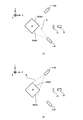
- FIGS. 3 (a) to 3 (f) is a cross-sectional view or a plan view showing the relationship between the irradiated portion irradiated with the processing light and the molten pool.
- FIGS. 4 (a) to 4 (b) is a plan view showing the relationship between the irradiated portion irradiated with the processing light and the molten pool.
- FIG. 5A to 5E is a cross-sectional view showing a state in which a certain region on the work is irradiated with processing light and a modeling material is supplied.
- FIGS. 6 (a) to 6 (c) is a cross-sectional view showing a process of forming a three-dimensional structure.
- FIG. 7 is a cross-sectional view schematically showing an observation device for observing a work using work light and molten pool light.
- FIG. 8 shows the magnitude relationship between the intensity of the work light and the intensity of the molten pool light.
- FIG. 9 is a graph showing an example of the wavelength range of the illumination light.
- FIG. 10 is a plan view showing an example of an observation image captured by the imaging device.
- FIG. 11 is a graph showing an example of the wavelength range of the illumination light.
- FIG. 12 is a graph showing the filter characteristics of the filter member.
- FIG. 13 is a graph showing the intensities of the illumination light and the molten pool light.
- FIG. 14 is a plan view showing an observation image displayed on the display.
- FIGS. 15 (a) to 15 (d) is a plan view showing an image displayed on the display.
- FIG. 16 is a flowchart showing a flow of an example of the condition setting operation.
- FIG. 17 is a plan view showing an example of an observation image generated by the imaging device.
- FIG. 18 schematically shows how the processing conditions are set.
- FIG. 19 is a flowchart showing a flow of an example of machining control operation.
- FIG. 20 is a plan view showing an example of the extracted molten pool image.
- FIG. 21 is a plan view showing an example of a work image.
- FIG. 22 is a plan view showing an example of a work image in which the removed image portion is removed.
- FIG. 23 is a plan view showing a reliability map.
- FIG. 24 schematically shows how a work image is generated using a reliability map.
- 25 (a) and 25 (b) are graphs showing the relationship between the brightness of the molten pool image and the intensity of the illumination light.
- Each of FIGS. 26 (a) and 26 (b) is a graph showing the relationship between the brightness of the work image and the intensity of the illumination light.
- FIG. 27 is a plan view showing an observation image generated in the third modification.
- FIG. 28A is a cross-sectional view showing a lighting device that emits illumination light from the first direction
- FIG. 28B is a cross-sectional view showing a lighting device that emits illumination light from the second direction.
- FIG. 29 (a) is a cross-sectional view showing a lighting device that emits illumination light from the first direction
- FIG. 29 (b) is a cross-sectional view showing the lighting device that emits illumination light from the second direction.
- FIG. 30A is a cross-sectional view showing a first illuminating device that emits illumination light
- FIG. 30B is a cross-sectional view showing a second illuminating device that emits illumination light.
- FIG. 31 is a cross-sectional view showing the structure of the processing system of the fifth modification.
- FIG. 32 is a cross-sectional view showing the structure of the processing system of the sixth modification.
- the laser overlay welding method includes direct metal deposition, directed energy deposition, laser cladding, laser engineered net shaping, direct light fabrication, and laser consolidation.
- Foundation Shape Deposition Manufacturing, Wire-Feed Laser Deposition, Gas Through Wire, Laser Powder Fusion, Laser Metal Forming, Selective Laser Powder Remelting, Laser Direct It may also be referred to as casting, laser powder deposition, laser additive manufacturing, or laser rapid forming.
- each of the X-axis direction and the Y-axis direction is a horizontal direction (that is, a predetermined direction in the horizontal plane), and the Z-axis direction is a vertical direction (that is, a direction orthogonal to the horizontal plane). Yes, it is assumed that it is substantially in the vertical direction).
- the rotation directions (in other words, the inclination direction) around the X-axis, the Y-axis, and the Z-axis are referred to as the ⁇ X direction, the ⁇ Y direction, and the ⁇ Z direction, respectively.
- the Z-axis direction may be the direction of gravity.
- the XY plane may be horizontal.
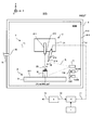
- FIG. 1 is a cross-sectional view showing an example of the structure of the processing system SYS of the present embodiment.
- FIG. 2 is a system configuration diagram showing an example of the system configuration of the processing system SYS of the present embodiment.
- the processing system SYS can form a three-dimensional structure ST (a three-dimensional object (three-dimensional object) having a size in any of the three-dimensional directions). Specifically, the processing system SYS can form the three-dimensional structure ST on the work W that is the basis for forming the three-dimensional structure ST. The processing system SYS may be able to form a three-dimensional structure ST on the work W by performing additional processing on the work W. When the work W is the stage 31, which will be described later, the processing system SYS may be able to form the three-dimensional structure ST on the stage 31. When the work W is an existing structure held by the stage 31 (or placed on the stage 31), the processing system SYS can form the three-dimensional structure ST on the existing structure. It may be.
- the processing system SYS may form a three-dimensional structure ST integrated with the existing structure.
- the operation of forming the three-dimensional structure ST integrated with the existing structure can be regarded as equivalent to the operation of adding a new structure to the existing structure.
- the existing structure may be, for example, a repair-required product having a defective portion.
- the processing system SYS may form a three-dimensional structure in the repair-required product so as to fill the defective portion of the repair-required product.
- the processing system SYS may form a three-dimensional structure ST separable from the existing structure.
- FIG. 1 shows an example in which the work W is an existing structure held by the stage 31. Further, in the following, the description will proceed with reference to an example in which the work W is an existing structure held by the stage 31.
- the processing system SYS can form the three-dimensional structure ST by the laser overlay welding method. That is, it can be said that the processing system SYS is a 3D printer that forms an object by using the laminated modeling technology.
- the laminated modeling technique is also referred to as rapid prototyping, rapid manufacturing, or adaptive manufacturing.
- the processing system SYS has a material supply device 1, a processing device 2, a stage device 3, a light source 4, and a gas supply device 5, as shown in FIGS. 1 and 2.
- the material supply device 1 supplies the modeling material M to the processing device 2. Specifically, the material supply device 1 and the processing device 2 (particularly, the material nozzle 212 described later) are connected via a supply pipe 11. The material supply device 1 supplies the modeling material M to the processing device 2 via the supply pipe 11. At this time, the material supply device 1 is desired according to the required amount so that the modeling material M required for the processing device 2 to perform additional processing per unit time is supplied to the processing device 2. A quantity of modeling material M may be supplied.
- the modeling material M is a material that can be melted by irradiation with a processing light EL having a predetermined intensity or higher.
- a modeling material M for example, at least one of a metal material and a resin material can be used.
- the modeling material M other materials different from the metal material and the resin material may be used.
- the modeling material M is a powdery material. That is, the modeling material M is a powder.
- the powder may contain a granular material in addition to the powdery material.
- the modeling material M may contain, for example, a powder having a particle size within the range of 90 micrometers ⁇ 40 micrometers.
- the average particle size of the powder constituting the modeling material M may be, for example, 75 micrometers, may be in the range of 10 micrometers to 25 micrometers, or may be any other size. good.
- the modeling material M does not have to be powder, and for example, a wire-shaped modeling material or a gaseous modeling material may be used.
- the processing device 2 forms the three-dimensional structure ST using the modeling material M supplied from the material supply device 1.
- the processing apparatus 2 includes a processing head 21 and a head drive system 22.
- the processing head 21 includes an irradiation optical system 211 and a material nozzle (that is, a supply system or a supply device for supplying the modeling material M) 212.
- the processing head 21 and the head drive system 22 are housed in the chamber space 63IN. However, at least a part of the processing head 21 and / or the head drive system 22 may be arranged in the external space 64OUT, which is the space outside the housing 6.
- the external space 64OUT may be a space accessible to the operator of the processing system SYS.
- the irradiation optical system 211 is an optical system (for example, a condensing optical system) for emitting the processed light EL from the injection unit 213. Specifically, the irradiation optical system 211 is optically connected to the light source 4 that emits the processed light EL via an optical transmission member 41 such as an optical fiber or a light pipe. The irradiation optical system 211 emits processed light EL propagating from the light source 4 via the optical transmission member 41. The irradiation optical system 211 emits the processing light EL so that the processing light EL advances in the chamber space 63IN.
- an optical transmission member 41 such as an optical fiber or a light pipe.
- the irradiation optical system 211 emits processed light EL propagating from the light source 4 via the optical transmission member 41.
- the irradiation optical system 211 emits the processing light EL so that the processing light EL advances in the chamber space 63IN.
- the irradiation optical system 211 irradiates the processing light EL downward (that is, the ⁇ Z side) from the irradiation optical system 211.
- a stage 31 is arranged below the irradiation optical system 211.
- the irradiation optical system 211 irradiates the work W with the processing light EL.
- the irradiation optical system 211 processes the processing light EL into a target irradiation region EA_tgt set on the work W or in the vicinity of the work W as a region to be irradiated (typically focused). It is possible to irradiate light EL.
- the state of the irradiation optical system 211 can be switched between a state in which the target irradiation region EA_tgt is irradiated with the processing light EL and a state in which the target irradiation region EA_tgt is not irradiated with the processing light EL under the control of the control device 8.
- the direction of the processed light EL emitted from the irradiation optical system 211 is not limited to directly below (that is, coincident with the ⁇ Z axis direction), and is, for example, a direction tilted by a predetermined angle with respect to the Z axis. May be good.
- a supply outlet 214 is formed in the material nozzle 212.
- the material nozzle 212 supplies the molding material M from the supply outlet 214 (eg, ejects, ejects, ejects, or sprays).
- the material nozzle 212 is physically connected to the material supply device 1 which is the supply source of the modeling material M via the supply pipe 11 and the mixing device 12.
- the material nozzle 212 supplies the modeling material M supplied from the material supply device 1 via the supply pipe 11 and the mixing device 12.
- the material nozzle 212 may pump the modeling material M supplied from the material supply device 1 via the supply pipe 11.
- the modeling material M from the material supply device 1 and the gas for transportation (that is, the pumping gas, that is, an inert gas such as nitrogen or argon) are mixed in the mixing device 12 and then the supply pipe 11 is connected. It may be pumped to the material nozzle 212 via. As a result, the material nozzle 212 supplies the modeling material M together with the conveying gas.
- the transporting gas for example, purge gas supplied from the gas supply device 5 is used.
- a gas supplied from a gas supply device different from the gas supply device 5 may be used.
- the material nozzle 212 is drawn in a tubular shape in FIG. 1, the shape of the material nozzle 212 is not limited to this shape.
- the material nozzle 212 supplies the modeling material M toward the chamber space 63IN.
- the material nozzle 212 supplies the modeling material M downward (that is, the ⁇ Z side) from the material nozzle 212.
- a stage 31 is arranged below the material nozzle 212. When the work W is mounted on the stage 31, the material nozzle 212 supplies the modeling material M toward the work W or the vicinity of the work W.
- the traveling direction of the modeling material M supplied from the material nozzle 212 is a direction inclined by a predetermined angle (an acute angle as an example) with respect to the Z-axis direction, but even if it is on the ⁇ Z side (that is, directly below). good.
- the material nozzle 212 is aligned with the irradiation optical system 211 so that the irradiation optical system 211 supplies the modeling material M toward the target irradiation region EA_tgt that irradiates the processing light EL. That is, the target supply region MA_tgt and the target irradiation region EA_tgt set on or near the work W as the region where the material nozzle 212 supplies the modeling material M coincide with (or at least partially overlap). As described above, the material nozzle 212 and the irradiation optical system 211 are aligned.
- the material nozzle 212 and the irradiation optical system 211 are aligned so that the material nozzle 212 supplies the modeling material M to the molten pool MP (described later) formed by the processing light EL emitted from the irradiation optical system 211. It may have been.
- the head drive system 22 moves the processing head 21.
- the head drive system 22 moves the processing head 21 within the chamber space 63IN, for example.
- the head drive system 22 moves the machining head 21 along at least one of the X-axis, the Y-axis, and the Z-axis.
- the target irradiation area EA_tgt and the target supply area MA_tgt can be positioned at any position on the work W or in the chamber space 63IN on the X-axis and the Y-axis, respectively. Move along at least one side.
- the head drive system 22 may move the machining head 21 along at least one rotation direction in the ⁇ X direction, the ⁇ Y direction, and the ⁇ Z direction in addition to at least one of the X-axis, the Y-axis, and the Z-axis. .. In other words, the head drive system 22 may rotate the machining head 21 around at least one of the X-axis, Y-axis, and Z-axis. The head drive system 22 may change the posture of the processing head 21 around at least one of the X-axis, the Y-axis, and the Z-axis.
- the head drive system 22 includes an actuator such as a motor, for example.
- the head drive system 22 moves the machining head 21, the relative positions of the machining head 21 and the work W supported by the stage 31 and the stage 31 change. That is, the relative positions of the irradiation optical system 211 and the material nozzle 212 (supply outlet 214) and the stage 31 and the work W are changed. Therefore, the head drive system 22 may function as a position changing device for changing the relative positional relationship between each of the irradiation optical system 211 and the material nozzle 212 (supply outlet 214) and each of the stage 31 and the work W. good.
- the head drive system 22 may function as a position changing device for changing the relative positional relationship between the target irradiation region EA_tgt and each of the stage 31 and the work W. Further, when the relative positions of the processing head 21, the stage 31, and the work W are changed, the target irradiation area EA_tgt and the target supply area MA_tgt (furthermore, the molten pool MP) move relative to the work W. Therefore, the head drive system 22 may function as a moving device that moves the target irradiation region EA_tgt and the target supply region MA_tgt (furthermore, the molten pool MP) relative to the work W.
- the stage device 3 includes a stage 31.
- the stage 31 is housed in the chamber space 63IN.
- the stage 31 can support the work W.
- the state in which the work W supports the work W may mean a state in which the work W is directly or indirectly supported by the stage 31.
- the stage 31 may be able to hold the work W. That is, the stage 31 may support the work W by holding the work W. Alternatively, the stage 31 does not have to be able to hold the work W.
- the work W may be placed on the stage 31. That is, the stage 31 may support the work W placed on the stage 31. At this time, the work W may be mounted on the stage 31 without being clamped.
- the stage 31 Since the stage 31 is housed in the chamber space 63IN, the work W supported by the stage 31 is also housed in the chamber space 63IN. Further, the stage 31 can release the held work W when the work W is held.
- the irradiation optical system 211 described above irradiates the processing light EL at least a part of the period during which the stage 31 supports the work W.
- the material nozzle 212 described above supplies the modeling material M during at least a part of the period in which the stage 31 supports the work W.
- the stage 31 may be provided with a mechanical chuck, a vacuum suction chuck, or the like in order to hold the work W.
- the light source 4 emits infrared light as processed light EL, for example. However, light of other wavelengths (for example, at least one of visible light and ultraviolet light) may be used as the processed light EL.
- the processed light EL includes a laser beam.
- the light source 4 may include a laser light source such as a semiconductor laser.
- the laser light source at least one of a laser diode (LD: Laser Diode), a fiber laser, a CO 2 laser, a YAG laser, an excimer laser and the like can be mentioned.
- the processing light EL does not have to be a laser beam, and the light source 4 may include an arbitrary light source (for example, at least one such as an LED (Light Emitting Diode) and a discharge lamp).
- the gas supply device 5 is a supply source of purge gas for purging the chamber space 63IN.
- the purge gas contains an inert gas.
- the inert gas nitrogen gas or argon gas can be mentioned.
- the gas supply device 5 is connected to the chamber space 63IN via a supply port 62 formed in the partition member 61 of the housing 6 and a supply pipe 51 connecting the gas supply device 5 and the supply port 62.
- the gas supply device 5 supplies purge gas to the chamber space 63IN via the supply pipe 51 and the supply port 62.
- the chamber space 63IN becomes a space purged by the purge gas.
- the purge gas supplied to the chamber space 63IN may be discharged from a discharge port (not shown) formed in the partition wall member 61.
- the gas supply device 5 may be a cylinder in which an inert gas such as nitrogen gas or argon gas is stored. When the inert gas is nitrogen gas, the gas supply device 5 may be a nitrogen gas generator that generates nitrogen gas from the atmosphere as a raw material.
- the purge gas supplied to the chamber space 63IN may have a flow velocity above the molten pool MP. That is, the purge gas may flow above the molten pool MP.
- substances such as fume generated from the molten pool MP (furthermore, the irradiation position of the processing light EL and the target irradiation region EA_tgt) may be removed from the space above the molten pool MP by the purge gas.
- the supply port for supplying the purge gas flowing above the molten pool MP may be formed separately from the supply port 62. In this case, the supply port for supplying the purge gas flowing above the molten pool MP may be formed in the vicinity of the target irradiation region EA_tgt.
- the gas supply device 5 supplies the mixing device 12 to which the modeling material M from the material supply device 1 is supplied in addition to the chamber space 63IN.
- Purge gas may be supplied.
- the gas supply device 5 may be connected to the mixing device 12 via a supply pipe 52 that connects the gas supply device 5 and the mixing device 12.
- the gas supply device 5 supplies the purge gas to the mixing device 12 via the supply pipe 52.
- the modeling material M from the material supply device 1 is supplied toward the material nozzle 212 through the supply pipe 11 by the purge gas supplied from the gas supply device 5 via the supply pipe 52 (specifically,). , Pumped).
- the gas supply device 5 may be connected to the material nozzle 212 via the supply pipe 52, the mixing device 12, and the supply pipe 11.
- the material nozzle 212 supplies the modeling material M together with the purge gas for pumping the modeling material M from the supply outlet 214.
- the housing 6 is a storage device that accommodates at least a part of each of the processing device 2, the stage device 3, and the observation system 7 in the chamber space 63IN, which is the internal space of the housing 6.
- the housing 6 includes a partition member 61 that defines a chamber space 63IN.
- the partition member 61 is a member that separates the chamber space 63IN from the external space 64OUT of the housing 6.
- the partition member 61 faces the chamber space 63IN via its inner wall 611, and faces the outer space 64OUT via its outer wall 612. In this case, the space surrounded by the partition member 61 (more specifically, the space surrounded by the inner wall 611 of the partition member 61) becomes the chamber space 63IN.
- the partition member 61 may be provided with a door that can be opened and closed.
- This door may be opened when the work W is placed on the stage 31.
- the door may be opened when the work W and / or the modeled object is taken out from the stage 31.
- the door may be closed during processing (ie, during additional processing or joining processing).
- the partition member 61 may be provided with an observation window (not shown) for visually recognizing the chamber space 63IN from the external space 64OUT of the housing 6.
- the observation system 7 is a system for observing an object to be observed.
- the observation object includes the work W.
- the three-dimensional structure ST is formed on the work W. Therefore, the observation object may include the work W on which the three-dimensional structure ST is formed.
- the three-dimensional structure ST is formed by sequentially forming a modeled object such as a structural layer SL. Therefore, the observation object may include a work W on which a modeled object for forming the three-dimensional structure ST is formed (that is, a work W on which the three-dimensional structure ST being formed is formed). ..
- the work W as an observation object is, in addition to the work W itself, a modeled object formed on the work W (typically, at least three-dimensional structure ST and structural layer SL.
- the observation object may include an object other than the work W.
- the observation object may include a stage 31.
- the observation object may include the irradiation optical system 211.
- the observation object may include the material nozzle 212.
- the observation object may include the housing 6.
- the observation system 7 includes a lighting device 71, an observation device 72, and a filter member 73.
- the lighting device 71 emits illumination light IL.
- the illuminating device 71 irradiates the object to be observed with the emitted illumination light IL.
- the observation object is illuminated by the illumination light IL.
- the illumination device 71 is a device that illuminates the observation object with the illumination light IL.
- the observation object includes the work W processed by the processing apparatus 2.
- the illuminating device 71 may illuminate at least a part of the work W with the illuminating light IL.
- the illuminating device 71 may illuminate the portion of the work W irradiated with the processing light EL (that is, the portion where the modeled object is formed by the additional processing) with the illuminating light IL.
- the illuminating device 71 may illuminate the portion of the work W that is not irradiated with the processing light EL (that is, the portion where the modeled object is not formed by the additional processing) with the illumination light IL.
- a portion of the work W that has not yet been irradiated with the processed light EL but is scheduled to be irradiated with the processed light EL in the future that is, a modeled object is formed in the future although the modeled object has not yet been formed by the additional processing.
- the part to be performed may be illuminated with the illumination light IL.
- the illuminating device 71 may illuminate the portion of the work W that is not scheduled to be irradiated with the processing light EL (that is, the portion where the modeled object is not scheduled to be formed by the additional processing) with the illumination light IL.
- the illuminating device 71 illuminates an object different from the work W (for example, stage 31 or the like). It may be irradiated with IL.
- the observation device 72 observes the object to be observed. Specifically, the observation device 72 observes the observation object illuminated by the illumination light IL.
- the observation device 72 may observe an observation object that is not illuminated by the illumination light IL.
- the observation device 72 detects the light from the observation object. Therefore, the observation device 72 may be referred to as a detection device.
- the observation object when the observation object is irradiated with the illumination light IL, the reflected light, scattered light, and transmitted light of the illumination light IL are emitted from the area irradiated with the illumination light IL (typically, at least a part of the observation object).
- Light containing at least one of is emitted.
- the observation object since the observation object includes the work W, the light including at least one of the reflected light, the scattered light, and the transmitted light of the illumination light IL from the observation object is the reflection of the illumination light IL from the work W. It may contain at least one of light, scattered light and transmitted light.
- the light including at least one of the reflected light, the scattered light and the transmitted light of the illumination light IL from the work W includes at least one of the reflected light, the scattered light and the transmitted light of the illumination light IL from the work W itself. It may also contain at least one of the reflected light, the scattered light and the transmitted light of the illumination light IL from the modeled object (for example, at least one of the three-dimensional structure ST and the structural layer SL) formed on the work W. May be good. Therefore, in the following, for convenience of explanation, the light including at least one of the reflected light, the scattered light, and the transmitted light of the illumination light IL from the work W, which is an observation object, is referred to as “work light WL”.
- the observation device 72 may detect at least a part of the work light WL from the work W in order to observe the work W.
- the work W when the work W is irradiated with the processing light EL, it is the part of the work W that has been irradiated with the processing light EL (that is, the part of the work W in which the target irradiation region EA_tgt is set. Light may be emitted from (may be referred to as "part EA").
- part EA Light may be emitted from
- a molten pool MP is formed in the work W. That is, the molten pool MP is formed in the region of the work W including the irradiated portion EA.
- the molten pool MP emits light (hereinafter, referred to as "melted pond light ML" for convenience of explanation).
- the molten pool MP is an aggregate of self-luminous liquid metals.
- Such molten pool light ML may include light due to thermal radiation (eg, blackbody radiation).
- the observation device 72 may detect at least a part of the molten pool light ML in order to observe the work W.
- the observation device 72 detects at least a part of the light from the irradiated portion EA irradiated with the processing light EL in the work W in addition to or in place of the molten pond light ML. You may.
- the irradiated portion EA currently irradiated with the processing light EL (hereinafter, “covered”.
- the position of the irradiation unit EA_curent ”) and the position of the molten pool MP may be the same.
- the size of the irradiated portion EA_curent and the size of the molten pool MP may be the same.
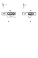
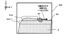
- the "size” in the present embodiment is a one-dimensional size corresponding to a width or a length along a predetermined direction (for example, a size in a direction along a modeling surface MS, and is in the X-axis direction and Y. It may include a size along at least one of the axial directions). Further, the "size” may include a two-dimensional size corresponding to the area. Further, the “size” may include a three-dimensional size corresponding to the volume. Alternatively, the size of the irradiated portion EA_curent and the size of the molten pool MP may be different. For example, as shown in FIGS.
- the size of the irradiated portion EA_curent may be smaller than the size of the molten pool MP. .. That is, the irradiated portion EA_curent may be included in the molten pool MP.
- the molten pool MP is schematically shown in the hatched region, and the irradiated portion EA is outlined. It is shown schematically in the area. The position of the irradiated portion EA_curent and the position of the molten pool MP may be different, or the size of the irradiated portion EA_curent may be larger than the size of the molten pool MP.
- the head drive system 22 moves the processing head 21 as described above, the irradiated portion EA to which the processing light EL is irradiated moves on the work W.
- the molten pool MP is the irradiated portion EA_curent currently irradiated with the processed light EL and the processed light EL in the past. May be formed in a region that straddles both the irradiated portion EA (hereinafter referred to as “irradiated portion EA_past”) that has been irradiated with.
- the irradiated portion EA that emits the light detected by the observation device 72 may include both the irradiated portion EA_curent and the irradiated portion EA_past.
- the molten pool MP is formed in the irradiated portion EA_past without being formed in the irradiated portion EA_curent. May be good. Such a situation may occur when the processing head 21 does not irradiate the work W with the processing light EL.
- the irradiated portion EA that emits the light detected by the observation device 72 does not include the irradiated portion EA_curent, but may include the irradiated portion EA_past.
- the machining system SYS has a shape in which the Y-axis direction is the longitudinal direction and the X-axis direction is the lateral direction.
- An example of processing will be described. That is, in the present embodiment, an example in which the processing system SYS processes a work W having a relatively thin thickness in the X-axis direction will be described.
- the shape of the work W processed by the processing system SYS is not limited. That is, the processing system SYS may process the work W having an arbitrary shape.
- the observation device 72 images the observation object in order to observe the work W. Therefore, the observation device 72 includes an image pickup device 721.
- the image pickup device 721 is, for example, a camera.
- the camera may be a general-purpose camera including an image sensor and a color filter (for example, a Bayer array color filter).
- the image pickup apparatus 721 generates an image of the observation object (work W in the present embodiment) by imaging the observation object (work W in the present embodiment).
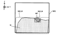
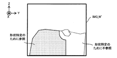
- the image generated by the image pickup apparatus 721 will be referred to as an “observation image IMG”.
- the image pickup device 721 is an image pickup device (in other words, at least one of the work light WL caused by the illumination light IL described above and at least one of the molten pool light ML caused by the molten pool MP) from the work W.
- it is a light receiving element and may be referred to as a light receiving unit).
- the observation image IMG is output from the image sensor. Therefore, the observation result of the observation device 72 (that is, the light detection result by the observation device 72) may include the observation image IMG. Since the work W is reflected in the observation image IMG, it can be said that the observation image IMG includes information based on the work W (particularly, the work W illuminated by the illumination light IL).
- observation image IMG is generated by detecting at least one of the work light WL and the molten pond light ML
- the observation image IMG also includes information based on at least one of the work light WL and the molten pond light ML. I can say.
- the image pickup device 721 of the observation device 72 is arranged so that the optical axis of the optical system included in the image pickup device 721 is parallel to the lateral direction (that is, the X-axis direction) of the work W. NS. Further, the lighting device 71 also illuminates the work W with the illumination light IL from the lateral direction (that is, the X-axis direction) of the work W.
- the arrangement positions of the lighting device 71 and the imaging device 721 are not limited to the example shown in FIG.
- the lighting device 71 may be arranged at an arbitrary position where the work W can be illuminated by the illumination light IL.
- the image pickup apparatus 721 may be arranged at an arbitrary position where the work W can be imaged.
- the observation device 72 may include a single image pickup device 721.
- the observation device 72 may include a plurality of image pickup devices 721.
- the observation device 72 may include a plurality of image pickup devices 721 for the work W from different directions.
- Such a plurality of image pickup devices 721 may form a stereo camera.
- the filter member 73 is arranged between the observation object (work W in this embodiment) and the observation device 72.
- the observation device 72 observes the work W via the filter member 73. Specifically, at least a part of the light from the work W (for example, at least one of the work light WL caused by the illumination light IL described above and the molten pond light ML caused by the molten pool MP) passes through the filter member 73. The light is incident on the observation device 72 (particularly, the image pickup device 721). The observation device 72 detects the light from the work W through the filter member 73.
- the filter member 73 is the light of at least a part of the wavelength range of the light from the work W (for example, at least one of the work light WL caused by the illumination light IL described above and the molten pond light ML caused by the molten pool MP). Is a passable member.
- the filter member 73 is a member that dims or blocks light in a wavelength range different from the wavelength range of light that can pass through the filter member 73.
- the filter member 73 is a member that dims or blocks light in a wavelength range different from the wavelength range of the work light WL and the wavelength range of the molten pool light ML. Therefore, the filter member 73 can function as a bandpass filter.
- the control device 8 controls the operation of the processing system SYS.
- the control device 8 may include, for example, an arithmetic unit and a storage device.
- the arithmetic unit may include, for example, at least one of a CPU (Central Processing Unit) and a GPU (Graphics Processing Unit).
- the storage device may include, for example, a memory.
- the control device 8 performs processing using an image (that is, image processing). Therefore, the arithmetic unit may include an image processing processor for performing image processing, and the storage device is a buffer memory for image processing (that is, a memory for temporarily storing an image to be image processed). May include. In this case, the control device 8 may perform image processing using the image processing processor and the buffer memory.
- the display 9 displays an image. Therefore, the control device 8 may include a display controller that controls the display 9, and the storage device is a buffer memory for displaying an image (that is, a memory that temporarily stores an image to be displayed, for example. Display RAM) may be included.
- the storage device is a buffer memory for displaying an image (that is, a memory that temporarily stores an image to be displayed, for example. Display RAM) may be included.
- the control device 8 functions as a device that controls the operation of the processing system SYS by executing a computer program by the arithmetic unit.
- This computer program is a computer program for causing the arithmetic unit to perform (that is, execute) the operation described later to be performed by the control device 8. That is, this computer program is a computer program for causing the control device 8 to function so that the processing system SYS performs the operation described later.
- the computer program executed by the arithmetic unit may be recorded in a storage device (that is, a recording medium) included in the control device 8, or any storage built in the control device 8 or externally attached to the control device 8. It may be recorded on a medium (for example, a hard disk or a semiconductor memory). Alternatively, the arithmetic unit may download the computer program to be executed from an external device of the control device 8 via the network interface.
- the control device 8 may control the emission mode of the processed light EL by the irradiation optical system 211.
- the injection mode may include, for example, at least one of the intensity of the processing light EL and the injection timing of the processing light EL.
- the emission mode is, for example, the emission time of pulsed light, the emission period of pulsed light, and the ratio of the length of emission time of pulsed light to the emission period of pulsed light (so-called so-called emission period). , Duty ratio) may be included.
- the control device 8 may control the movement mode of the processing head 21 by the head drive system 22.
- the movement mode may include, for example, at least one of a movement amount, a movement speed, a movement direction, and a movement timing.
- the control device 8 may control the supply mode of the modeling material M by the material nozzle 212.
- the supply mode of the modeling material M by the material nozzle 212 is mainly determined by the supply mode of the modeling material M by the material supply device 1. Therefore, controlling the supply mode of the modeling material M by the material supply device 1 may be regarded as equivalent to controlling the supply mode of the modeling material M by the material nozzle 212.
- the supply mode may include, for example, at least one of a supply amount (particularly, a supply amount per unit time) and a supply timing.
- the control device 8 is the observation result of the observation system 7 (that is, the observation result of the observation device 72, the output of the observation device 72, and the detection of light from the work W by the observation device 72.
- the operation of the machining system SYS may be controlled based on the result). That is, the control device 8 may control the operation of the processing system SYS based on the observation image IMG captured by the image pickup device 721. For example, the control device 8 may control the processing device 2 based on the observation image IMG. The details of the operation of controlling the processing system SYS based on the observation image IMG will be described in detail later.
- the control device 8 does not have to be provided inside the processing system SYS.
- the control device 8 may be provided as a server or the like outside the processing system SYS.
- the control device 8 and the processing system SYS may be connected by a wired and / or wireless network (or a data bus and / or a communication line).
- a wired network for example, a network using a serial bus type interface represented by at least one of IEEE1394, RS-232x, RS-422, RS-423, RS-485 and USB may be used.
- a network using a parallel bus interface may be used.
- a network using an Ethernet (registered trademark) compliant interface represented by at least one of 10BASE-T, 100BASE-TX and 1000BASE-T may be used.
- a network using radio waves may be used.
- An example of a network using radio waves is a network conforming to IEEE 802.1x (for example, at least one of wireless LAN and Bluetooth®).
- a network using infrared rays may be used.
- a network using optical communication may be used.
- the control device 8 and the processing system SYS may be configured so that various types of information can be transmitted and received via the network.
- control device 8 may be able to transmit information such as commands and control parameters to the processing system SYS via the network.
- the processing system SYS may include a receiving device that receives information such as commands and control parameters from the control device 8 via the network. Even if the processing system SYS is provided with a transmission device (that is, an output device that outputs information to the control device 8) that transmits information such as commands and control parameters to the control device 8 via the network. good.
- the first control device that performs a part of the processing performed by the control device 8 is provided inside the processing system SYS, the second control device that performs the other part of the processing performed by the control device 8 is provided.
- the control device may be provided outside the processing system SYS.
- the recording medium for recording the computer program executed by the control device 8 includes a CD-ROM, a CD-R, a CD-RW, a flexible disk, an MO, a DVD-ROM, a DVD-RAM, a DVD-R, a DVD + R, and a DVD.
- -Used by at least one of optical disks such as RW, DVD + RW and Blu-ray (registered trademark), magnetic media such as magnetic tape, magneto-optical disks, semiconductor memories such as USB memory, and other media capable of storing programs. May be done.
- the recording medium may include a device capable of recording a computer program (for example, a general-purpose device or a dedicated device in which the computer program is implemented in a state in which it can be executed in at least one form such as software and firmware).
- each process or function included in the computer program may be realized by a logical processing block realized in the control device 8 by the control device 8 (that is, the computer) executing the computer program. It may be realized by hardware such as a predetermined gate array (FPGA, ASIC) included in the control device 8, or a logical processing block and a partial hardware module that realizes a part of the hardware are mixed. It may be realized in the form of.
- the display 9 is a display device capable of displaying a desired image under the control of the control device 8.
- the display 9 may display an image based on the observation result of the observation system 7 (that is, the output of the observation device 72 and the output of the image pickup device 721).
- the display 9 may display an image (that is, an image related to the observation result) based on the observation result of the observation system 7 (that is, the output of the observation device 72 and the output of the image pickup device 721).
- the display 9 may display an image relating to the observation result of the observation system 7 (that is, the output of the observation device 72 and the output of the image pickup device 721).
- a specific example of the image displayed by the display 9 will be described in detail later.
- the display 9 may include a display included in the processing system SYS (that is, a display built in the processing system SYS).
- the display 9 may include a display that can be externally attached to the processing system SYS.
- a display provided in a device different from the processing system SYS may display a desired image under the control of the control device 8.
- a display provided in at least one of a notebook computer and a tablet terminal may display a desired image under the control of the control device 8.
- the processing system SYS does not have to include the display 9.
- the machining system SYS performs an operation for forming the three-dimensional structure ST by performing additional machining on the work W (hereinafter, referred to as “additional machining operation”).
- the observation system 7 may perform an operation for observing the work W (hereinafter, referred to as “observation operation”) during at least a part of the period during which the additional processing operation is performed.
- the observation operation for observing the work W includes an operation for detecting light from the work W.
- control operation for controlling the machining system SYS using the result of the observation operation (that is, the observation result of the work W) (hereinafter, "control operation"). ") May be performed. Therefore, in the following, the additional processing operation, the observation operation, and the control operation will be described in order.
- an additional processing operation (an operation for performing additional processing on the work W to form a three-dimensional structure ST) will be described.
- the processing system SYS forms the three-dimensional structure ST by the laser overlay welding method. Therefore, the processing system SYS may form the three-dimensional structure ST by performing an existing additional processing operation (in this case, a modeling operation) based on the laser overlay welding method.
- an existing additional processing operation in this case, a modeling operation
- an additional processing operation for forming the three-dimensional structure ST by using the laser overlay welding method will be briefly described.
- the processing system SYS forms the three-dimensional structure ST on the work W based on the three-dimensional model data (for example, CAD (Computer Aided Design) data) of the three-dimensional structure ST to be formed.
- the 3D model data the measurement data of the three-dimensional object measured by at least one of the measuring device shown in the figure X provided in the processing system SYS and the 3D shape measuring machine provided separately from the processing system SYS is used. May be done.
- the processing system SYS forms, for example, a plurality of layered partial structures (hereinafter, referred to as “structural layers”) SLs arranged along the Z-axis direction in order.
- the processing system SYS sequentially forms a plurality of structural layers SL obtained by cutting the three-dimensional structure ST into round slices along the Z-axis direction.
- a three-dimensional structure ST which is a laminated structure in which a plurality of structural layers SL are laminated, is formed.
- the flow of the operation of forming the three-dimensional structure ST by forming the plurality of structural layers SL one by one in order will be described.
- each structural layer SL will be described with reference to FIGS. 5 (a) to 5 (e).
- the processing head under the control of the control device 8, the processing head is set so that the target irradiation region EA_tgt is set in a desired region on the modeling surface MS corresponding to the surface of the work W or the surface of the formed structural layer SL. Move 21.
- the processing system SYS irradiates the target irradiation region EA_tgt with the processing light EL from the irradiation optical system 211.
- the focus position (that is, the condensing position) of the processed light EL may coincide with the modeling surface MS.
- the focus position that is, the condensing position
- a molten pool (that is, a pool of metal melted by the processing light EL) MP is formed in the irradiated portion EA'on the modeling surface MS irradiated with the processing light EL.
- the processing system SYS supplies the modeling material M from the material nozzle 212 under the control of the control device 8.
- the target supply region MA_tgt to which the modeling material M is supplied coincides with the target irradiation region EA_tgt as described above, the target supply region MA_tgt includes at least a part of the region where the molten pool MP is formed. .. Therefore, as shown in FIG.
- the processing system SYS supplies the modeling material M to the molten pool MP from the material nozzle 212.
- the modeling material M supplied to the molten pool MP is melted.
- the processing light EL is not irradiated to the molten pool MP as the processing head 21 moves
- the modeling material M melted in the molten pool MP is cooled and solidified (that is, solidified).
- the solidified modeling material M is deposited on the modeling surface MS. That is, a modeled object is formed by the deposit of the solidified modeling material M.
- a series of modeling processes including formation of the molten pool MP by irradiation with such processing light EL, supply of the modeling material M to the molten pool MP, melting of the supplied modeling material M, and solidification of the molten modeling material M can be performed.
- the processing head 21 is repeatedly moved relative to the modeling surface MS along the XY plane. That is, when the processing head 21 moves relative to the modeling surface MS, the target irradiation region EA_tgt also moves relative to the modeling surface MS. Therefore, a series of modeling processes is repeated while moving the target irradiation region EA_tgt relative to the modeling surface MS along the XY plane (that is, in the two-dimensional plane).
- the processing system SYS sets the target irradiation region EA_tgt in the region where the modeled object is to be formed on the modeling surface MS, while setting the target irradiation region EA_tgt in the region where the modeling object is not desired to be formed on the modeling surface MS. do not. Therefore, the processed light EL is not irradiated on the region where the modeled object is desired to be formed on the modeled surface MS, but is irradiated on the region where the modeled object is not desired to be formed on the modeled surface MS.
- the processing system SYS moves the target irradiation region EA_tgt along the predetermined movement locus on the modeling surface MS, and creates the processing light EL at the timing according to the distribution mode of the region where the modeled object is to be formed. Irradiate to.
- the molten pool MP also moves on the modeling surface MS along the movement locus corresponding to the movement locus of the target irradiation region EA_tgt.
- the molten pool MP is sequentially formed on the modeling surface MS in the portion of the region along the movement locus of the target irradiation region EA_tgt that is irradiated with the processing light EL.
- the target supply region MA_tgt also moves on the modeling surface MS along the movement locus corresponding to the movement locus of the target irradiation region EA_tgt. Will move.
- a structural layer SL corresponding to an aggregate of the modeled objects made of the modeling material M solidified after being melted is formed on the modeling surface MS.
- the structural layer SL corresponding to the aggregate of the shaped objects formed on the modeling surface MS in the pattern corresponding to the moving locus of the molten pool MP (that is, the shape corresponding to the moving locus of the molten pool MP in a plan view).
- the structural layer SL) to have is formed.
- the processing system SYS irradiates the target irradiation region EA_tgt with the processing light EL and stops the supply of the modeling material M. good.
- the processing system SYS supplies the modeling material M to the target irradiation region EA_tgt, and the processing light having an intensity that does not allow the molten pool MP.
- the EL may be irradiated to the target irradiation area EA_tgt.
- the processing system SYS moves the target irradiation region EA_tgt with respect to the modeling surface MS by moving the processing head 21 with respect to the modeling surface MS.
- the machining system SYS moves the stage 31 with respect to the machining head 21 (that is, moves the modeling surface MS).
- the target irradiation region EA_tgt may be moved with respect to the modeling surface MS.
- the stage device 3 may include a stage drive system for moving the stage 31.
- the processing system SYS may move the target irradiation region EA_tgt with respect to the modeling surface MS by driving the galvano mirror provided in the irradiation optical system 211.
- the processing system SYS repeatedly performs the operation for forming such a structural layer SL under the control of the control device 8 based on the three-dimensional model data. Specifically, first, the control device 8 creates slice data by slicing the three-dimensional model data at a stacking pitch. Note that data obtained by partially modifying this slice data may be used according to the characteristics of the processing system SYS.
- the processing system SYS performs the operation for forming the first structural layer SL # 1 on the modeling surface MS corresponding to the surface of the work W with the three-dimensional model data corresponding to the structural layer SL # 1 (that is, the structure). It is performed based on the slice data corresponding to the layer SL # 1.
- the structural layer SL # 1 is formed on the modeling surface MS as shown in FIG. 6A.
- the processing system SYS sets the surface (that is, the upper surface) of the structural layer SL # 1 on the new modeling surface MS, and then forms the second structural layer SL # 2 on the new modeling surface MS. do.
- the control device 8 first controls the head drive system 22 so that the machining head 21 moves along the Z axis. Specifically, the control device 8 controls the head drive system 22 so that the target irradiation region EA_tgt and the target supply region MA_tgt are set on the surface of the structural layer SL # 1 (that is, a new modeling surface MS).
- the processing head 21 is moved toward the + Z side. As a result, the focus position of the processing light EL coincides with the new modeling surface MS.
- the processing system SYS operates on the structural layer SL # 1 based on the slice data corresponding to the structural layer SL # 2 in the same operation as the operation of forming the structural layer SL # 1 under the control of the control device 8.
- the structural layer SL # 2 is formed on the surface.
- the structural layer SL # 2 is formed as shown in FIG. 6 (b).
- the same operation is repeated until all the structural layers SL constituting the three-dimensional structure ST to be formed on the work W are formed.
- the three-dimensional structure ST is formed by the laminated structure in which a plurality of structural layers SL are laminated.
- observing the work W includes observing both the work W and the molten pool MP formed in the work W. This is because, in the control operation described later, the control device 8 receives information obtained from the observation result of the work W (for example, information on the characteristics of the work W) and information obtained from the observation result of the molten pool MP (for example, the molten pool MP). This is because the machining system SYS is controlled by using both the information regarding the characteristics of the above.
- the lighting device 71 described in the present embodiment is not used, there may be a technical problem that it is difficult to properly observe both the work W and the molten pool MP. Therefore, the technical problems that may occur when observing the work W and the molten pool MP will be described below. After that, by explaining the observation operation performed by the observation system 7 of the present embodiment, how the observation system 7 solves this technical problem will be described.
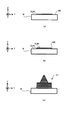
- FIG. 7 is a cross-sectional view schematically showing an observation device 72 for observing the work W using the work light WL and the molten pool light ML, which are the lights from the work W.
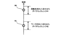
- FIG. 8 is a schematic diagram showing the magnitude relationship between the intensity of the work light WL and the intensity of the molten pool light ML.
- the intensities of the work light WL and the molten pond light ML are used for explanation, but this explanation is also valid when the brightness of the work light WL and the molten pond light ML is used.
- the observation device 72 included in the observation system of the comparative example observes the work W by detecting the work light WL and the molten pool light ML.
- the work light WL is mainly the light from the work W irradiated with the molten pond light ML (or ambient light) from the molten pool MP. .. That is, the work light WL is mainly the molten pond light ML (or ambient light) emitted from the work W by irradiating the work W with the molten pond light ML (or ambient light) emitted by the molten pool MP. Includes at least one of reflected light, scattered light and transmitted light.
- the intensity of the molten pool light ML (typically, the intensity at the peak wavelength described later) is relatively likely to be much higher than the intensity of the work light WL. This is because the molten pond light ML is the light emitted by the pool of molten metal, while the work light WL is the light containing at least one of the reflected light, the scattered light and the transmitted light of the light irradiated to the work W. Because it is nothing more than.
- the exposure condition of the image pickup apparatus 721 is that one of the work light WL and the molten pond light ML is appropriately exposed. It is often set to be a condition.
- the dynamic range of the image pickup apparatus 721 (that is, the range from the minimum value to the maximum value of the optical signal that can be identified and detected by the image pickup apparatus 721) varies depending on the exposure condition of the image pickup apparatus 721.
- the image pickup apparatus 721 may not be able to generate an observation image IMG in which both the work W and the molten pool MP are properly reflected. That is, the observation system of the comparative example may not be able to properly observe both the work W and the molten pool MP.
- the dynamic range # 1 in FIG. 8 is the dynamic range when the work W is imaged by adjusting the exposure to the intensity region of the molten pool light ML.
- the image pickup apparatus 721 can appropriately detect the molten pool light ML, an observation image IMG in which the molten pool MP is appropriately reflected is generated.
- the intensity of the work light WL is much smaller than the intensity of the molten pool light ML, it is difficult for the image sensor to detect the work light WL.
- the work W (particularly, the portion of the work W other than the portion located in the vicinity of the molten pool MP) may not be properly reflected in the generated observation image IMG.
- the work W (particularly, the portion of the work W other than the portion located near the molten pool MP) may be black.
- the dynamic range # 2 in FIG. 8 is the dynamic range when the work W is imaged by adjusting the exposure to the region of the intensity of the work light WL.
- the image pickup apparatus 721 can appropriately detect the work light WL, an observation image IMG in which the work W is appropriately reflected is generated.
- the generated observation image IMG since a part of the image sensor that has received the molten pool light ML may be saturated, the generated observation image IMG has the molten pool MP (furthermore, the molten pool in the work W). The part located near the MP) may not be reflected properly.
- the molten pool MP (furthermore, the portion of the work W located near the molten pool MP) is reflected in a pure white state. That is, there is a possibility that the molten pool MP (furthermore, the portion of the work W located in the vicinity of the molten pool MP) is not reflected in the generated observation image IMG in an identifiable state.
- the observation system 7 does not take any measures, even if it tries to observe both the work W and the molten pool MP, it may not be possible to properly observe both the work W and the molten pool MP. There is. That is, the observation system 7 may not be able to generate an observation image IMG in which both the work W and the molten pool MP are properly reflected. Therefore, in the present embodiment, in order to appropriately observe both the work W and the molten pool MP, the observation operation described below is performed. That is, the observation system 7 performs the observation operation described below in order to generate an observation image IMG in which both the work W and the molten pool MP are appropriately reflected.
- the wavelength of the illumination light IL is used in order to appropriately observe both the work W and the molten pool MP.
- the region ⁇ range_IL is set to an appropriate wavelength region.
- the "wavelength range of light” in the present embodiment may mean "the range of wavelengths at which the intensity of light is equal to or higher than a predetermined lower limit threshold value THL".
- the wavelength range ⁇ range_IL of the illumination light IL is set to a wavelength range different from the wavelength range ⁇ range_ML of the molten pool light ML. Will be done.
- the wavelength range ⁇ range_WL of the work light WL also has a wavelength range different from the wavelength range ⁇ range_ML of the molten pool light ML.
- the observation image IMG includes a molten pool MP exhibiting a color corresponding to the wavelength region ⁇ range_ML and a wavelength region ⁇ range_IL.
- the work W that exhibits the color corresponding to is reflected. Therefore, both the molten pool MP and the work W (particularly, the portion of the work W other than the molten pool MP) are reflected in the observation image IMG in a state in which they can be distinguished from each other by color.
- the control device 8 described later can extract the work image IMG_W corresponding to the work W and the molten pool image IMG_M corresponding to the molten pool MP from the observation image IMG.
- the "wavelength region ⁇ range_IL is different from the wavelength region ⁇ range_ML" state typically means "the wavelength region ⁇ range_IL does not overlap with the wavelength region ⁇ range_ML".
- the wavelength region ⁇ range_IL is typically set so that the peak wavelength ⁇ peek_IL of the illumination light IL is different from the peak wavelength ⁇ peek_ML of the molten pool light ML. Will be done.
- the "peak wavelength of light” in the present embodiment may mean "the wavelength at which the intensity of light is maximized”.
- the wavelength region ⁇ range_IL is different from the wavelength region ⁇ range_ML
- "a part of the wavelength region ⁇ range_IL does not overlap with the wavelength region ⁇ range_ML
- another part of the wavelength region ⁇ range_IL overlaps with the wavelength region ⁇ range_ML”.
- It may include a state.
- FIG. 11 which is a graph showing another example of the wavelength region ⁇ range_IL of the illumination light IL
- the intensity of the illumination light IL is larger than the intensity of the molten pond light ML at the peak wavelength ⁇ peak_IL. (In particular, it may be set to be higher than the first predetermined strength).
- the intensity of the work light WL from the work W irradiated with the illumination light IL becomes larger than the intensity of the molten pond light ML (particularly, the intensity becomes larger than the second predetermined intensity). May be set as.
- the work W having a color corresponding to the wavelength region ⁇ range_IL is appropriately reflected in the observation image IMG.
- the wavelength region ⁇ range_IL In order to set the wavelength region ⁇ range_IL so that the intensity of the work light WL is larger than the intensity of the molten pool light ML at the peak wavelength ⁇ peak_IL, the wavelength region ⁇ range_IL has a peak wavelength ⁇ peak_IL, and the peak wavelength ⁇ peak_IL has a peak wavelength ⁇ range_ML.
- the intensity may be set to have a wavelength ⁇ smal_ML that is smaller than the predetermined intensity ITH.
- the wavelength region ⁇ range_IL may be set so that the peak wavelength ⁇ peak_IL has a wavelength different from the wavelength ⁇ range_ML at which the intensity of the molten pool light ML is greater than the predetermined intensity ITH in the wavelength region ⁇ range_ML.
- the predetermined intensity ITH may be set to a value smaller than the intensity of the illumination light IL at the peak wavelength ⁇ peek_IL (particularly, a value smaller than the first predetermined intensity).
- the predetermined intensity ITH may be set to a value smaller than the intensity of the work light WL at the peak wavelength ⁇ peek_IL (particularly, a value smaller than the second predetermined intensity).
- the wavelength region ⁇ range_IL may be set to a wavelength region on the shorter wavelength side than the wavelength region ⁇ range_ML.
- infrared light which is light having a relatively long wavelength
- the wavelength range ⁇ range_IL is separated from the wavelength range of the processing light EL.
- the influence of the processing light EL on the observation of the work W becomes relatively small.
- the wavelength range is such that infrared light is used as the processing light EL and the peak wavelength ⁇ peak_ML of the molten pool light ML corresponds to the wavelength of red light in visible light.
- ⁇ range_IL shows an example set to include the wavelength of blue light of visible light. In this case, the molten pool MP, which mainly exhibits red color, and the work W, which mainly exhibits blue color, are reflected in the observation image IMG.
- the wavelength range ⁇ range_IL may be set to include at least a part of the wavelength range of visible light.
- the work W is reflected in the observation image IMG so that the user of the processing system SYS can see it. Therefore, the user can appropriately grasp the state of the work W from the observation image IMG.
- the wavelength range ⁇ range_IL does not have to include the wavelength range of visible light.
- the wavelength range ⁇ range_IL may include at least a part of a wavelength range of light different from visible light.
- the wavelength region ⁇ range_IL may include at least one wavelength region of ultraviolet light.
- the dynamic range of the image pickup apparatus 721 is set so that the intensity region of the work light WL is appropriately exposed. May be good.
- the intensity of the illumination light IL is smaller than the intensity of the molten pond light ML (for example, the intensity at the peak wavelength ⁇ peek_ML) (particularly, it is smaller than a predetermined first allowable value)
- the intensity of the work light WL is melted. It may be smaller than the intensity of the pond light ML (particularly, it may be smaller than a predetermined second allowable value).
- the observation system 7 secondly allows the difference between the intensity of the work light WL detected by the imaging device 721 and the intensity of the molten pond light ML detected by the imaging device 721 using the filter member 73. It may be reduced to less than or equal to the value.
- the transmittance of the filter member 73 with respect to the light of the wavelength range ⁇ range_IL of the illumination light IL is the wavelength range of the molten pool light ML. It may have a filter characteristic that is different from the transmittance of the filter member 73 with respect to the light of ⁇ range_ML.
- the filter member 73 may have a filter characteristic that the transmittance of the filter member 73 with respect to the light of the wavelength region ⁇ range_ML is lower than the transmittance of the filter member 73 with respect to the light of the wavelength region ⁇ range_IL.
- the intensity of the illumination light IL was smaller than the intensity of the molten pond light ML (particularly, the first allowable value or more). Even if it is small), the difference between the intensity of the work light WL and the intensity of the molten pond light ML becomes smaller than the second allowable value.
- the transmittance of the filter member 73 may be set so that the difference between the intensity of the work light WL and the intensity of the molten pool light ML can be reduced to a second allowable value or less.
- FIG. 12 shows the intensity of the work light WL before passing through the filter member 73 and the light passing through the filter member 73.
- An example is shown in which the intensity of the later work light WL is the same.
- the intensity of the work light WL after passing through the filter member 73 may be smaller than the intensity of the work light WL before passing through the filter member 73.
- the filter member 73 can pass light in a part of the wavelength range ⁇ range_ML, while light in a part of the other wavelength range ⁇ range_ML can pass through. It may have a filter characteristic that it is not possible.
- the filter member 73 can pass light in a part of the wavelength range including the peak wavelength ⁇ peek_ML in the wavelength range ⁇ range_ML, while light in the remaining part of the wavelength range ⁇ range_ML can pass through. It may have a filter characteristic that it is not possible.
- the filter member 73 has a filter characteristic that the wavelength range (that is, the transmission bandwidth) of the light component that can pass through the filter member 73 among the light contained in the wavelength range ⁇ range_ML is relatively narrowed.
- the filter member 73 filters out of the light contained in the wavelength range ⁇ range_ML as compared with the wavelength range (that is, the transmission bandwidth) of the light component that can pass through the filter member 73 among the light contained in the wavelength range ⁇ range_WL. It may have a filter characteristic that the wavelength range (that is, the transmission bandwidth) of the light component that can pass through the member 73 is relatively narrow. In this case, even if the intensity of the molten pond light ML is extremely large with respect to the intensity of the illumination light IL, the difference between the intensity of the work light WL and the intensity of the molten pond light ML should be reduced to the second allowable value or less. Can be done.
- the molten pool MP is still reflected in the observation image IMG.
- the same effect as that realized when the transmittance of the filter member 73 with respect to the light of the wavelength region ⁇ range_IL is different from the transmittance of the filter member 73 with respect to the light of the wavelength region ⁇ range_ML can be enjoyed.
- the molten pool light ML received by the image pickup apparatus 721 and the work light WL are clearly separated optically, there is an advantage that image processing using the observation image IMG, which will be described later, becomes easy.
- the filter member 73 with respect to the light in the wavelength range ⁇ range_IL When the wavelength range (that is, the transmitted bandwidth) of the light component that can pass through the filter member 73 among the light contained in the wavelength range ⁇ range_ML is relatively narrow, the filter member 73 with respect to the light in the wavelength range ⁇ range_IL.
- the transmittance does not have to be different from the transmittance of the filter member 73 with respect to light in the wavelength region ⁇ range_ML.
- both the molten pond light ML and the work light WL are visible light, even with the image pickup apparatus 721 composed of the above-mentioned general-purpose camera, the work W and the molten pond MP are reflected in the observation.
- the work W can be imaged so that the image IMG is generated.
- the filter characteristics of the filter member 73 may be set based on an experiment using the work W (or a sample imitating the work W). For example, the molten pool light ML formed by irradiating the work W (or a sample imitating the work W) with the processing light EL is detected, and the illumination light IL is set to the work W (or the work W). The work light WL generated by irradiating the sample) is detected, and the intensities of the molten pond light ML and the work light WL are specified based on the detection results of the molten pond light ML and the work light WL.
- the filter characteristics (for example, the transmission rate described above) of the filter member 73 may be set based on the specific result of the intensity of the ML and the work light WL.
- the observation system 7 is a filter member. 73 may not be provided.
- the observation system 7 does not include the filter member 73. You may.
- the observation system 7 may include the filter member 73. ..
- the transmittance of the filter member 73 with respect to the light of the wavelength region ⁇ range_IL of the illumination light IL does not have to be different from the transmittance of the filter member 73 with respect to the light of the wavelength region ⁇ range_ML of the molten pool light ML.
- the transmittance of the filter member 73 with respect to the light of the wavelength region ⁇ range_IL of the illumination light IL may be the same as the transmittance of the filter member 73 with respect to the light of the wavelength region ⁇ range_ML of the molten pool light ML.
- the wavelength range (that is, the transmission bandwidth) of the light component that can pass through the filter member 73 among the light contained in the wavelength range ⁇ range_ML does not have to be relatively narrow.
- the display 9 may display the observation image IMG under the control of the control device 8. That is, as shown in FIG. 14 showing the observation image IMG displayed on the display 9, the display 9 has both the work W exhibiting the color corresponding to the wavelength region ⁇ range_WL and the molten pool MP exhibiting the color corresponding to the wavelength region ⁇ range_ML.
- the observation image IMG in which the image is reflected may be displayed. As a result, the user can appropriately grasp at least one of the state of the work W and the state of the molten pool MP from the observation image IMG.
- the control device 8 can extract the work image IMG_W and the molten pool image IMG_M from the observation image IMG.
- the display 9 displays either the work image IMG_W or the molten pool image IMG_M under the control of the control device 8, while the display 9 does not display either the work image IMG_W or the molten pool image IMG_M. May be good.
- the user can appropriately grasp at least one of the state of the work W and the state of the molten pool MP.
- the display 9 may display the work image IMG_W while not displaying the molten pool image IMG_M.
- FIG. 15A the display 9 may display the work image IMG_W while not displaying the molten pool image IMG_M.
- the display 9 may display the molten pool image IMG_M while not displaying the work image IMG_W.
- the display 9 may display both the work image IMG_W and the molten pool image IMG_M under the control of the control device 8. Even in this case, the user can appropriately grasp at least one of the state of the work W and the state of the molten pool MP.
- the display 9 may display the work image IMG_W and the molten pool image IMG_M side by side.
- the display 9 may display the work image IMG_W and the molten pool image IMG_M in an overlapping manner. In this case, the image displayed by the display 9 may be substantially the same as the observed image IMG.
- the processing system SYS generates a three-dimensional structure ST by sequentially forming a plurality of structural layers SL.
- the control device 8 is a work image in which the formed structural layer SL # n is reflected during the period during which the structural layer SL # n of the nth layer (where n is an integer of 1 or more) is formed.
- IMG_W a condition setting operation for setting the processing conditions used for forming the n + 1th structural layer SL # n + 1 is performed.
- control device 8 uses the molten pool image IMG_M during the period of forming the n + 1th structural layer SL # n + 1, and uses the molten pool image IMG_M to set the n + 1th structural layer SL under the processing conditions set in the condition setting operation.
- a machining control operation is performed to control the machining system SYS so as to form # n + 1.
- the control device 8 mainly uses the work image IMG_W to perform the condition setting operation, and mainly uses the molten pool image IMG_M to perform the machining control operation. That is, the control device 8 uses the work image IMG_W and the molten pool image IMG_M obtained from the observation image IMG for different purposes.
- condition setting operation and a machining control operation will be described in order.
- the control operation performed by the machining system SYS is not limited to the control operation described below.
- the control device 8 may perform an arbitrary first operation based on the work image IMG_W and an arbitrary second operation based on the molten pool image IMG_M.
- the control device 8 may perform an arbitrary control operation based on the work image IMG_W and the molten pool image IMG_M.
- the control device 8 may use the work image IMG_W for any first purpose and the molten pool image IMG_M for any second purpose.
- the control device 8 may use the work image IMG_W and the molten pool image IMG_M for the same purpose.
- control device 8 performs a control operation using either the work image IMG_W or the molten pool image IMG_M, but does not perform a control operation using either the work image IMG_W or the molten pool image IMG_M. May be good. That is, the control device 8 may perform the control operation without using either the work image IMG_W or the molten pool image IMG_M, while the control device 8 does not use either the work image IMG_W or the molten pool image IMG_M.
- FIG. 16 is a flowchart showing a flow of an example of the condition setting operation.
- the condition setting operation shown in FIG. 16 is an example of a condition setting operation performed during at least a part of the period in which the nth structural layer SL # n is formed by the above-mentioned additional processing operation.
- FIG. 17 is a plan view showing an example of the acquired observation image IMG.
- the processing apparatus 2 forms the structural layer SL # n on the structural layer SL # n-1. Further, in the example shown in FIG. 17, the processing apparatus 2 forms the structural layer SL # n so that the molten pool MP moves toward the + Y side with respect to the work W.
- the control device 8 acquires the work image IMG_W corresponding to the work W from the observation image IMG acquired in step S11 (step S12).
- a molten pool MP having a color corresponding to the wavelength range ⁇ range_ML and a work W having a color corresponding to the wavelength range ⁇ range_IL that is, the work W itself and the work W
- the modeled object is reflected. Therefore, the control device 8 can extract the work image IMG_W corresponding to the work W from the observation image IMG by analyzing the color of the observation image IMG. That is, the control device 8 can extract the work image IMG_W (see FIG. 15A) corresponding to the work light WL from the observation image IMG.
- the control device 8 identifies the shape of the work W (that is, the current or actual shape) based on the work image IMG_W extracted in step S12 (step S13). In particular, the control device 8 specifies the shape (that is, the current or actual shape) of the structural layer SL # n currently formed by the processing device 2 (step S13). For example, the control device 8 may specify the shape of the surface of the structural layer SL # n currently formed by the processing device 2.
- the control device 8 sets the machining conditions used for forming the structural layer SL # n + 1 based on the shape of the work W specified in step S13 (particularly, the shape of the structural layer SL # n) (step S14). ). Specifically, as shown in FIG. 18, which schematically shows how the machining conditions are set, the control device 8 has the actual shape of the work W specified in step S13 (particularly, the actual shape of the structural layer SL # n). The difference between the shape) and the ideal shape of the work W after the structural layer SL # n is formed (that is, the ideal shape of the structural layer SL # n) is calculated. After that, the control device 8 forms the structural layer SL # n + 1 so that the difference between the actual shape of the work W and the ideal shape of the work W becomes small due to the formation of the structural layer SL # n + 1. Set the processing conditions used for.
- the difference between the actual shape of the work W and the ideal shape of the work W is the ideal formation amount (typically the thickness) of each portion of the structural layer SL # n. It corresponds to a shortage amount or an excess amount with respect to the ideal thickness).
- the amount of the first portion of the structural layer SL # n (for example, the insufficiently processed portion SLp1 shown in FIG. 18) is insufficient for the ideal amount of formation, it is formed on the structural layer SL # n. If the amount of the formed portion of the structural layer SL # n + 1 formed on the insufficiently processed portion SLp1 is increased, the shape of the work W approaches the ideal shape.
- the amount of formation of the second portion of the structural layer SL # n (for example, the overworked portion SLp2 shown in FIG. 18) is excessive with respect to the ideal amount of formation, it is on the structural layer SL # n. If the amount of the portion of the structural layer SL # n + 1 formed in the above-processed portion SLp2 is reduced, the shape of the work W approaches the ideal shape. Therefore, in the control device 8, the amount of the portion formed on the under-processed portion SLp1 of the structural layer SL # n + 1 is relatively large, and the over-processed portion SLp2 of the structural layer SL # n + 1 is formed.
- the processing conditions of the structural layer SL # n + 1 may be set so that the amount of the formed portion is relatively small. For example, in the control device 8, the larger the shortage amount of the formed amount of the under-processed portion SLp1 with respect to the ideal forming amount, the larger the formed amount of the portion of the structural layer SL # n + 1 formed on the under-processed portion SLp1.
- the processing conditions may be set as described above. For example, in the control device 8, the larger the excess amount of the formed amount of the overworked portion SLp2 with respect to the ideal forming amount, the smaller the formed amount of the portion of the structural layer SL # n + 1 formed on the overworked portion SLp2.
- the processing conditions may be set as described above.
- the amount of formation is not limited to the thickness, but may be a width (as an example, a size along the X-axis direction).
- the amount of formation of each part of the structural layer SL # n + 1 may depend on, for example, the size of the molten pool MP formed on the modeling surface MS when each part of the structural layer SL # n + 1 is formed.
- the processing conditions may include the size of the molten pool MP formed when the structural layer SL # n + 1 is formed (that is, the target value of the size of the molten pool MP).
- the size of the molten pool MP may include the size (so-called width) in the direction along the modeling surface MS (for example, the direction along the XY plane).
- the size of the molten pool MP may include the size (so-called height or depth) in the direction intersecting the modeling surface MS (for example, the Z-axis direction).
- the control device 8 is placed on the under-processed portion SLp1 of the structural layer SL # n + 1 as the insufficient amount of the formed amount of the under-processed portion SLp1 with respect to the ideal forming amount increases.
- the processing conditions may be set so that the molten pool MP for forming the formed portion becomes large.
- control device 8 melts the structural layer SL # n + 1 to form a portion of the structural layer SL # n + 1 formed on the overworked portion SLp2 as the excess amount of the overworked portion SLp2 formed increases with respect to the ideal forming amount. Machining conditions may be set so that the pond MP becomes small.
- the processing system SYS may change the size of the molten pool MP by, for example, controlling the intensity of the processing light EL.
- the processing system SYS may increase the size of the molten pool MP by increasing the intensity of the processing light EL.
- the processing system SYS may reduce the size of the molten pool MP by reducing the intensity of the processing light EL.
- the amount of each portion of the structural layer SL # n + 1 is determined by, for example, the irradiation time of the processing light EL when forming each portion of the structural layer SL # n + 1 in addition to or in place of the size of the molten pool MP described above. It may depend on each of the number of irradiations. For example, as the irradiation time of the processing light EL when forming each portion of the structural layer SL # n + 1 becomes longer, the amount of the modeling material M melted in each portion increases, so that each of the structural layers SL # n + 1 The amount of part formed may increase.
- the processing conditions include at least one of the irradiation time and the number of irradiations of the processing light EL when forming each portion of the structural layer SL # n + 1 (that is, the target value of at least one of the irradiation time and the number of irradiations). You may.
- the control device 8 processes the structural layer SL # n + 1 when forming a portion of the structural layer SL # n + 1 that is formed on the under-processed portion SLp1 as the amount of formation of the under-processed portion SLp1 increases.
- the processing conditions may be set so that at least one of the irradiation time and the number of irradiations of the optical EL is increased.
- the larger the excess amount of the formed amount of the overworked portion SLp2 with respect to the ideal forming amount the more the processing light is used when forming the portion of the structural layer SL # n + 1 formed on the overworked portion SLp2.
- the processing conditions may be set so that at least one of the EL irradiation time and the number of irradiations is reduced.
- the machining system SYS changes the size of the molten pool MP by controlling at least one of the irradiation time and the number of irradiations of the machining light EL for each region on the work W by controlling the movement mode of the machining head 11.
- the processing system SYS may control the number of times the processing light EL is irradiated by controlling the movement locus of the processing head 11.
- the processing system SYS may shorten the irradiation time of the processing light EL by increasing the moving speed of the processing head 11 during the period of irradiating each region on the work W with the processing light EL.
- the processing system SYS may lengthen the irradiation time of the processing light EL by reducing the moving speed of the processing head 11 during the period of irradiating each region on the work W with the processing light EL.
- an unformed portion in which the structural layer SL # n has not yet been formed (specifically, an unformed portion to be formed in a region on the + Y side of the portion corresponding to the molten pool MP). If a portion) is present, the control device 8 does not have to set the machining conditions used to form the structural layer SL # n + 1 on the unformed portion.
- the control device 8 may set the processing conditions used for forming the structural layer SL # n + 1 on the unformed portion after the unformed portion is formed. Therefore, in the present embodiment, it can be said that the control device 8 sequentially sets a part of the processing conditions for forming the structural layer SL # n + 1 in accordance with the formation of the structural layer SL # n.
- control device 8 forms the structural layer SL # n + 1 so that the graph showing the processing conditions shown in the lower part of FIG. 18 gradually extends toward the right side with the formation of the structural layer SL # n. It can be said that the processing conditions for this are set. However, as will be described later, the control device 8 may collectively set the entire processing conditions for forming the structural layer SL # n + 1 after the structural layer SL # n has been formed.
- control device 8 determines whether or not the formation of the structural layer SL # n is completed (step S15). If it is determined as a result of the determination in step S15 that the formation of the structural layer SL # n is not completed (step S15: No), the control device 8 repeats the processes from step S11 to step S14.
- step S15 if it is determined as a result of the determination in step S15 that the formation of the structural layer SL # n is completed (step S15: Yes), the control device 8 decides whether or not to finish setting the machining conditions. Determine (step S16). For example, when the structural layer SL # n + 1 is formed following the structural layer SL # n, the control device 8 has formed the structural layer SL # n + 1 during the period of forming the structural layer SL # n + 1.
- the processing conditions used for forming the structural layer SL # n + 2 of the n + 2nd layer may be set by using the work image IMG_W in which the image is reflected.
- the control device 8 may determine that the setting of the machining conditions is not completed. On the other hand, if the structural layer SL # n + 1 is not formed following the structural layer SL # n, the control device 8 may determine that the setting of the machining conditions is completed.
- step S16 If, as a result of the determination in step S16, it is determined that the setting of the machining conditions is not completed (step S16: No), the control device 8 increments the variable n by 1 (step S17), and then steps from step S11. The process up to S15 is repeated. On the other hand, when it is determined that the setting of the machining conditions is completed (step S16: Yes), the control device 8 ends the condition setting operation shown in FIG.
- the control device 8 uses the work image IMG_W in which the formed structural layer SL # n is reflected during the period of forming the structural layer SL # n, and the structural layer SL # n + 1 is used.
- the processing conditions for forming the above are set.
- the control device 8 uses the work image IMG_W in which the formed structural layer SL # n is reflected after the structural layer SL # n has been formed, and the processing conditions for forming the structural layer SL # n + 1. May be set.
- the image pickup device 721 images the formed structural layer SL # n
- the control device 8 captures the observation image IMG captured by the image pickup device 721.
- the work image IMG_W may be extracted, and the extracted work image IMG_W may be used to set processing conditions for forming the structural layer SL # n + 1.
- FIG. 19 is a flowchart showing a flow of an example of machining control operation.
- the condition setting operation shown in FIG. 19 is an example of a condition setting operation performed during at least a part of the period in which the n + 1th structural layer SL # n + 1 is formed by the above-mentioned processing operation.
- control device 8 acquires the observation image IMG from the observation system 7 (particularly, the image pickup device 721) (step S21).
- the control device 8 acquires the molten pool image IMG_M corresponding to the molten pool MP from the observation image IMG acquired in step S21 (step S22).
- the observation image IMG reflects the molten pool MP having a color corresponding to the wavelength range ⁇ range_ML and the work W having a color corresponding to the wavelength range ⁇ range_IL.
- the control device 8 can extract the molten pool image IMG_M corresponding to the molten pool MP from the observation image IMG. That is, the control device 8 can extract the molten pool image IMG_M (see FIG. 15B) corresponding to the molten pool light ML from the observation image IMG.
- the control device 8 specifies the size of the molten pool MP based on the molten pool image IMG_M extracted in step S22 (step S23). For example, as shown in FIG. 20, the size (so-called width) in the direction along the control device 8 and the modeling surface MS (for example, the direction along the XY plane) may be specified. For example, the size (so-called height or depth) in the direction (for example, the Z-axis direction) intersecting the control device 8 and the modeling surface MS may be specified.
- control device 8 determines whether or not the size of the molten pool MP specified in step S23 is the same as the target value of the size of the molten pool MP indicated by the machining conditions set in the condition setting operation. (Step S24).
- step S24 when it is determined that the size of the molten pool MP specified in step S23 is not the same as the target value (step S24: No), the control device 8 determines that the size of the molten pool MP is not the same.
- the characteristics of the processed optical EL are changed so as to be the same as the target value (step S25). That is, the control device 8 changes the characteristics of the processing light EL so as to form the molten pool MP having the same size as the target value in order to form the structural layer SL # n + 1 (step S25).
- step S24 determines whether the size of the molten pool MP specified in step S23 is the same as the target value (step S24: Yes).
- the control device 8 is subjected to the processing light EL. It is not necessary to change the characteristics of.
- the characteristics of the processed light EL may include the strength of the processed light EL. This is because, as the intensity of the processing light EL increases, the amount of energy transmitted from the processing light EL to the modeling surface MS increases, so that the molten pool MP formed increases.
- the characteristics of the processed light EL may include the intensity distribution of the processed light EL. This is because if the intensity distribution of the processing light EL changes, the distribution of the amount of energy transmitted from the processing light EL to the modeling surface MS changes, so that the size of the molten pool MP formed changes.
- control device 8 determines whether or not the formation of the structural layer SL # n + 1 is completed (step S26). If it is determined as a result of the determination in step S26 that the formation of the structural layer SL # n + 1 is not completed (step S26: No), the control device 8 repeats the processes from step S11 to step S25.
- step S26 determines whether or not to end the machining control operation.
- the control device 8 uses the molten pool image IMG_M during the period of forming the structural layer SL # n + 2.
- the machining system SYS may be controlled so as to form the structural layer SL # n + 2 under the machining conditions set in the condition setting operation.
- the control device 8 may determine that the machining control operation is not completed. On the other hand, if the structural layer SL # n + 2 is not formed following the structural layer SL # n + 1, the control device 8 may determine that the machining control operation is completed.
- step S27 If, as a result of the determination in step S27, it is determined that the machining control operation is not completed (step S27: No), the control device 8 increments the variable n by 1 (step S28), and then steps S21 to S26 Repeat the process up to. On the other hand, when it is determined to end the machining control operation (step S27: Yes), the control device 8 ends the machining control operation shown in FIG. X16.
- FIG. 19 shows an example of the machining control operation when the target value of the size of the molten pool MP is set as the machining condition in the condition setting operation.
- the control device 8 may perform the machining control operation shown in FIG. 19 even when the target value of the size of the molten pool MP is not set as the machining condition in the condition setting operation.
- the target value of the size of the molten pool MP used in step S24 of FIG. 19 may be set in advance, or may be appropriately set by an operation different from the condition setting operation shown in FIG.
- control device 8 may perform the machining control operation shown in FIG. 19 even when the machining conditions different from the target value of the size of the molten pool MP are set in the condition setting operation. That is, even when a machining condition different from the target value of the size of the molten pool MP is set in the condition setting operation, the control device 8 performs the same operation as the machining control operation shown in FIG. 19 to perform the work. Based on the image IMG_W, the machining system SYS may be controlled so as to machine the work W under the set machining conditions.
- the machining system SYS can appropriately observe both the work W and the molten pool MP by using the observation system 7. That is, the processing system SYS can generate an observation image IMG in which both the work W and the molten pool MP are appropriately reflected by using the observation system 7. Therefore, the processing system SYS can appropriately extract each of the work image IMG_W and the molten pool image IMG_M from the observation image IMG. As a result, the processing system SYS can appropriately form the three-dimensional structure ST by using the work image IMG_W and the molten pool image IMG_M.
- the control device 8 has the shape of the work W based on the work image IMG_W (particularly, the structural layer SL # currently formed by the processing device 2).
- the shape of n) is specified.
- the control device 8 generates a work image IMG_W'suitable for specifying the shape of the work W (particularly, the shape of the structural layer SL # n) from the work image IMG_W, and the work.
- the shape of the work W (particularly, the shape of the structural layer SL # n) is specified based on the image IMG_W'.
- the control device 8 removes at least one of the removed image portions IMG_RMV1 and IMG_RMV2 from the work image IMG_W in order to generate the work image IMG_W'. It may be removed. That is, as shown in FIG. 22, which is a plan view showing the work image IMG_W', the work image IMG_W' is an image generated by removing at least one of the removed image portions IMG_RMV1 and IMG_RMV2 from the work image IMG_W. May be good. Note that FIG. 22 shows an example of the work image IMG_W'in which both the removed image portion IMG_RMV1 and the IMG_RMV2 are removed.
- the removed image portion IMG_RMV1 is in the moving direction of the molten pool MP with respect to the work W in the work image IMG_W (that is, the moving direction of the irradiated portion EA irradiated with the processing light EL and the target irradiation region EA_tgt). Includes the image portion located on the front side.
- the removed image portion IMG_RMV1 is an image portion in which the modeling surface MS on which the molten pool MP is to be formed is reflected.
- the removed image portion IMG_RMV1 is an image portion in which the modeling surface MS on which the structural layer SL # n is formed is reflected. Therefore, it is highly possible that the structural layer SL # n is not reflected in the removed image portion IMG_RMV1.
- the work image IMG_W'from which the removed image portion IMG_RMV1 has been removed specifies the shape of the work W (particularly the shape of the structural layer SL # n) as compared with the work image IMG_W from which the removed image portion IMG_RMV1 has not been removed. It can be said that it is suitable for doing. This is because the shape of the modeling surface MS (that is, the structural layer SL # n-1) reflected in the removed image portion IMG_RMV1 may be erroneously recognized as a part of the shape of the structural layer SL # n. Because it becomes smaller.
- the removed image portion IMG_RMV2 includes an image portion located within a predetermined distance from the molten pool MP.
- the molten pool light ML having a relatively high intensity is emitted from the molten pool MP. Therefore, the portion of the work W located within a predetermined distance from the molten pool MP is appropriately reflected in the observation image IMG (furthermore, the work image IMG_W) due to the influence of the molten pool light ML having a relatively high intensity. It may not be crowded.
- the work image IMG_W'from which the removed image portion IMG_RMV2 has been removed specifies the shape of the work W (particularly the shape of the structural layer SL # n) as compared with the work image IMG_W from which the removed image portion IMG_RMV2 has not been removed. It can be said that it is suitable for doing.
- Each of the removed image portions IMG_RMV1 and IMG_RMV2 depends on the position of the molten pool MP in the observed image IMG (that is, the position where the molten pool light ML is emitted). Therefore, the control device 8 specifies the position of the molten pool MP in the observation image IMG (that is, the position where the molten pool light ML is emitted), and generates the work image IMG_W'based on the position of the specified molten pool MP. You may. Specifically, the control device 8 may specify the removed image portion IMG_RMV1 in the work image IMG_W based on the position of the specified molten pool MP and the moving direction of the molten pool MP.
- control device 8 may specify the removed image portion IMG_RMV2 in the work image IMG_W based on the position of the specified molten pool MP. After that, the control device 8 may generate the work image IMG_W'by removing the specified removed image portions IMG_RMV1 and IMG_RMV2 from the work image IMG_W.
- the control device 8 is substantially the range of the work image IMG_W that should be referred to for specifying the shape of the work W (that is, the work light that should be referred to for specifying the shape of the work W). It can be said that the range of WL) is specified.
- the control device 8 may use the reliability map CMAP shown in FIG. 23 in order to remove at least one of the removed image portions IMG_RMV1 and IMG_RMV2.
- the reliability map CMAP is a map showing the reliability of each part of the work image IMG_W.
- the reliability indicated by the reliability map CMAP is an index that quantitatively indicates whether or not each part of the work image IMG_W is suitable for an application for specifying the shape of the work W (particularly, the shape of the structural layer SL # n). be.
- the reliability indicated by the reliability map CMAP quantitatively indicates whether or not each part of the work image IMG_W should be referred to for identifying the shape of the work W (particularly the shape of the structural layer SL # n). It is an index.
- the reliability map CMAP indicates the reliability of each portion of the work image IMG_W so that the reliability of the removed image portions IMG_RMV1 and IMG_RMV2 in the work image IMG_W is relatively low.
- the reliability map CMAP indicates the reliability of each part of the work image IMG_W so that the reliability of the image parts other than the removed image parts IMG_RMV1 and IMG_RMV2 in the work image IMG_W is relatively high.
- the reliability map CMAP shown in FIG. 23 shows that the removed image portion IMG_RMV1 has the lowest reliability, the removed image portion IMG_RMV2 has the next lowest reliability, and the removed image portions IMG_RMV1 and IMG_RMV2 have the highest reliability. There is.
- the reliability map CMAP shown in FIG. 23 has the lowest reliability of the region located on the front side in the moving direction (that is, the machining direction) of the molten pool MP with respect to the work W when viewed from the molten pool MP, and the molten pool MP has the lowest reliability. It shows that the reliability of the region located within a predetermined distance from is the next lowest, and the reliability of the other regions is high.
- the control device 8 When the reliability map CMAP is used, as shown in the figure on the left side of FIG. 24, the control device 8 has a relatively low reliability image portion (for example, for example) of the work image IMG_W indicated by the reliability map CMAP.
- the work image IMG_W' may be generated by removing (the image portion corresponding to the reliability of "low” and "medium” shown in FIG. 23). As a result, the control device 8 can generate the work image IMG_W'relatively easily. After that, the control device 8 specifies the shape of the work W (particularly, the shape of the structural layer SL # n) based on the work image IMG_W'.
- the control device 8 sets the machining conditions by calculating the difference between the actual shape of the specified work W and the ideal shape of the work W.
- the control device 8 has a relative reliability indicated by the reliability map CMAP among the ideal shapes of the work W. It is not necessary to consider the shape corresponding to the lower part.
- the control device 8 may consider a shape corresponding to a portion of the ideal shape of the work W having a relatively high reliability indicated by the reliability map CMAP.
- the control device 8 has the actual shape of the specified work W and the ideal shape of the work W even when the reliability map CMAP is used. The difference can be calculated.
- the machining system SYS can more appropriately specify the shape of the work W (particularly, the shape of the structural layer SL # n). As a result, the machining system SYS can set the machining conditions more appropriately.
- the control device 8 has already set the structural layer during the period of forming the structural layer SL # n.
- the processing conditions for forming SL # n may be changed.
- the control device 8 may change the processing conditions for forming the already set structural layer SL # n based on the shape of the structural layer SL # n specified by the condition setting operation. Specifically, when the first portion of the structural layer SL # having a shape different from the ideal shape is formed in the first region of the modeling surface MS, the already set machining conditions are actually set. It may not have been appropriate.
- the control device 8 identifies the shape of the first portion of the formed structural layer SL # during the period of forming the structural layer SL # n, and has not yet been formed based on the specified shape.
- the processing conditions for forming the second portion of the structural layer SL # may be changed.
- the control device 8 makes the difference between the actual shape and the ideal shape of the second portion of the structural layer SL # small (typically zero) so that the second portion of the structural layer SL # becomes the first.
- the processing conditions for forming the two portions may be changed.
- the control device 8 is not only a first modification for specifying the shape of the work W (particularly, the shape of the structural layer SL # n) based on the work image IMG_W', but also the shape of the work W based on the work image IMG_W. Even in the above-mentioned case of specifying (particularly, the shape of the structural layer SL # n), the processing conditions for forming the already set structural layer SL # n during the period of forming the structural layer SL # n. May be changed.
- the control device 8 sets the processing conditions for forming the structural layer SL # n + 1 during the period of forming the structural layer SL # n. That is, the control device 8 presets the processing conditions for forming the structural layer SL # n + 1 before starting to form the structural layer SL # n + 1. However, the control device 8 does not have to set the processing conditions for forming the structural layer SL # n + 1 during the period of forming the structural layer SL # n. That is, the control device 8 does not have to set the processing conditions for forming the structural layer SL # n + 1 in advance before the structural layer SL # n is formed.
- the control device 8 may set the processing conditions for forming the structural layer SL # n + 1 during the period of forming the structural layer SL # n + 1. That is, the control device 8 presets the processing conditions for forming the structural layer SL # n + 1 after the structural layer SL # n + 1 has begun to be formed (that is, after the structural layer SL # n has been formed). You may. For example, the control device 8 identifies the shape of the structural layer SL # n on which the structural layer SL # n + 1 is to be formed based on the work image IMG_W after the structural layer SL # n + 1 has begun to be formed. You may.
- control device 8 sets the processing conditions for forming the structural layer SL # n + 1 to be formed based on the shape of the specified structural layer SL # n after starting to form the structural layer SL # n + 1. It may be set. Even if the processing conditions for forming the structural layer SL # n + 1 are set in advance before starting to form the structural layer SL # n + 1, the control device 8 forms the structural layer SL # n + 1. After starting, the shape of the structural layer SL # n to be formed on the structural layer SL # n + 1 is specified, and the structural layer SL to be formed is to be formed based on the shape of the specified structural layer SL # n. The processing conditions for forming # n + 1 may be changed.
- the control device 8 When setting the processing conditions for forming the structural layer SL # n + 1 during the period of forming the structural layer SL # n + 1, the control device 8 removes from the work image IMG_W at least one of the image portions IMG_RMV2 and IMG_RMV3.
- the shape of the structural layer SL # n may be specified based on the work image IMG_W'' generated by removing the above.
- the removed image portion IMG_RMV3 includes an image portion of the work image IMG_W located on the rear side in the moving direction of the molten pool MP with respect to the work W when viewed from the molten pool MP.
- the removed image portion IMG_RMV3 is an image portion in which the already formed structural layer SL # n + 1 is reflected.
- the work image IMG_W'' in which the removed image portion IMG_RMV3 is removed is compared with the work image IMG_W in which the removed image portion IMG_RMV3 is not removed. It can be said that it is suitable for specifying the shape (particularly, the shape of the structural layer SL # n).
- a reliability map CMAP showing the reliability of each part of the work image IMG_W is used so that the reliability of the image parts other than the removed image part IMG_RMV2 and IMG_RMV3 in the work image IMG_W is relatively high. May be good.
- control device 8 may control the lighting device 71 based on at least one of the observation image IMG, the work image IMG_W, and the molten pool image IMG_M.
- the control device 8 may control the lighting device 71 based on the brightness of the molten pool image IMG_M (or the portion corresponding to the molten pool image IMG_M in the observation image IMG, the same applies hereinafter in the second modification). good. Specifically, as shown in FIGS. 25 (a) and 25 (b), the control device 8 increases the intensity of the illumination light IL as the brightness of the molten pool image IMG_M increases. May be controlled. Note that FIG. 25A shows an example in which the intensity of the illumination light IL continuously increases as the brightness of the molten pool image IMG_M increases. FIG. 25B shows an example in which the intensity of the illumination light IL increases stepwise as the brightness of the molten pool image IMG_M increases.
- the control device 8 may control the lighting device 71 based on the brightness of the work image IMG_W (or the portion corresponding to the work image IMG_W in the observation image IMG, the same applies hereinafter in the second modification). Specifically, as shown in FIGS. 26A and 26B, the control device 8 sets the illumination device 71 so that the intensity of the illumination light IL decreases as the brightness of the work image IMG_W increases. You may control it. Note that FIG. 26A shows an example in which the intensity of the illumination light IL continuously decreases as the brightness of the work image IMG_W increases. FIG. 26B shows an example in which the intensity of the illumination light IL gradually decreases as the brightness of the work image IMG_W increases.
- the control device 8 may control the lighting device 71 based on the brightness of the molten pool image IMG_M and the brightness of the work image IMG_W. Specifically, the control device 8 increases the intensity of the illumination light IL when the average brightness of the molten pool image IMG_M is larger than the average brightness of the work image IMG_W by a first predetermined value or more. 71 may be controlled. In this case, the control device 8 may control the illumination device 71 so that the intensity of the illumination light IL increases as the difference between the average brightness of the molten pool image IMG_M and the average brightness of the work image IMG_W increases.
- the control device 8 sets the lighting device 71 so that the intensity of the illumination light IL becomes smaller when the average brightness of the molten pool image IMG_M is smaller than the average brightness of the work image IMG_W by a second predetermined value or more. You may control it. In this case, the control device 8 may control the illumination device 71 so that the intensity of the illumination light IL becomes smaller as the difference between the average brightness of the molten pool image IMG_M and the average brightness of the work image IMG_W increases.
- the integrated value of the brightness of each part (typically, each pixel) of the molten pool image IMG_M is divided by the area (typically the number of pixels) of the molten pool image IMG_M. It may be a value obtained by doing so.
- the average brightness of the work image IMG_W is obtained by dividing the integrated value of the brightness of each part (typically each pixel) of the work image IMG_W by the area (typically the number of pixels) of the work image IMG_W. It may be a value.
- the reason for using such an average brightness is that the area of the work image IMG_W and the area of the molten pool image IMG_M may be different.
- the brightness of the work image IMG_W becomes a constant brightness suitable for specifying the shape of the work W. Therefore, according to the second modification, the machining system SYS can more appropriately specify the shape of the work W. As a result, the machining system SYS can set the machining conditions more appropriately.
- the control device 8 controls the observation image IMG, the work image IMG_W, and the molten pool. At least one of the image IMG_M or the gain ⁇ of the image pickup apparatus 721 may be adjusted. At this time, the control device 8 may individually adjust the gain ⁇ _ML relating to the color corresponding to the wavelength region ⁇ range_ML of the molten pool light ML and the gain ⁇ _WL relating to the color corresponding to the wavelength region ⁇ range_WL of the work light WL.
- the control device 8 gains so that the gain ⁇ _WL relating to the color corresponding to the wavelength region ⁇ range_WL of the work light WL is larger than the gain ⁇ _ML relating to the color corresponding to the wavelength region ⁇ range_ML of the molten pool light ML.
- ⁇ _ML and ⁇ _WL may be adjusted.
- the brightness of the work image IMG_W becomes a brightness suitable for specifying the shape of the work W as compared with the case where the gain ⁇ is not adjusted.
- the machining system SYS can set the machining conditions more appropriately.
- the lighting device 71 may illuminate the modeling material M supplied from the material nozzle 212 with the illumination light IL in addition to or instead of the work W.
- the lighting device 71 illuminates the modeling material M (hereinafter referred to as “modeling material M1”) passing through the supply path between the material nozzle 212 and the work W (particularly, the target supply area MA_tgt) with the illumination light IL.
- the lighting device 71 may illuminate the modeling material M (hereinafter, referred to as “modeling material M2”) that is scattered by being bounced off by at least one of the work W and the stage 31 with the illumination light IL.
- the lighting device 71 may illuminate the modeling material M (hereinafter, referred to as “modeling material M3”) remaining on at least one of the work W and the stage 31 with the illumination light IL.
- modeling material M means at least one of the above-mentioned modeling materials M1 to M3.
- the observation device 72 may observe the modeling material M supplied from the material nozzle 212 in addition to or in place of the work W. Specifically, the observation device 72 may detect the light from the modeling material M supplied from the material nozzle 212 in addition to or in place of the work W. The observation device 72 may image the modeling material M supplied from the material nozzle 212 in addition to or in place of the work W. That is, in the third modification, the observation object may include the modeling material M supplied from the material nozzle 212.
- the observation image IMG has a modeling material M (which exhibits a color corresponding to the wavelength region ⁇ range_IL of the illumination light IL. Furthermore, in some cases, the work W) is reflected. Therefore, the control device 8 can extract the work image IMG_W in which the modeling material M is reflected from the observation image IMG. When the work image IMG_W in which the modeling material M is reflected is extracted, the control device 8 may control the supply mode of the modeling material M based on the work image IMG_W.
- control device 8 specifies the actual supply amount of the modeling material M to the molten pool MP based on the work image IMG_W so that the specified supply amount becomes the same as the target value of the supply amount of the modeling material M.
- the supply amount of the modeling material M to the molten pool MP may be controlled.
- the control device 8 may control the moving speed of the processing head 21 in order to control the supply amount of the modeling material M to the molten pool MP.
- the illuminating device 71 may illuminate the work W with the illumination light IL from each of a plurality of different directions. That is, the illumination device 71 may irradiate the work W with the illumination light IL from each of the plurality of different directions.
- the lighting device 71 may illuminate the first surface WS # 1 of the work W with the illumination light IL from the first direction.
- FIG. 28A shows an example in which the illuminating device 71 illuminates the first surface WS # 1 of the work W with the illumination light IL from an obliquely right direction when viewed from the work W.
- the illuminating device 71 illuminates the second surface WS # 2 of the work W different from the first surface WS # 1 from the second direction different from the first direction. It may be illuminated by IL.
- the observation system 7 may include a lighting drive system for moving the lighting device 71.
- the illuminating device 71 may illuminate the work W with the illuminating light IL so as to emit the illuminating light IL toward the observing device 72 from the first direction. That is, the illuminating device 71 may illuminate the work W with the illuminating light IL so as to emit the illuminating light IL in the direction in which the observing device 72 exists. In this case, the work W is typically arranged between the lighting device 71 and the observation device 72.
- FIG. 29A shows an example in which the lighting device 71 is arranged on the ⁇ X side of the work W and the observation device 72 is arranged on the + X side of the work W.
- the observation device 72 (imaging device 721) generates a negative image of the work W as the observation image IMG.
- the work W is such that the illumination device 71 emits the illumination light IL from a second direction different from the first direction toward a direction different from the observation device 72. May be illuminated with illumination light IL. That is, the illuminating device 71 may illuminate the work W with the illuminating light IL so as to emit the illuminating light IL in a direction different from the direction in which the observing device 72 exists.
- FIG. 29B shows an example in which both the lighting device 71 and the observation device 72 are arranged on the + X side of the work W.
- the observation device 72 (imaging device 721) generates a positive image of the work W as the observation image IMG.
- the lighting device 71 has a position where the illumination light IL can be emitted in the direction in which the observation device 72 exists and a position where the illumination light IL can be emitted in a direction different from the direction in which the observation device 72 exists. You may move between.
- the processing system SYS may include a plurality of lighting devices 71 in addition to moving the lighting device 71.
- Each of the plurality of lighting devices 71 may illuminate the work W with the illumination light IL from a plurality of different directions. That is, each of the plurality of lighting devices 71 may irradiate the work W with the illumination light IL from a plurality of different directions.
- the processing system SYS includes a lighting device 71 # 1 and a lighting device 71 # 2.
- the lighting device 71 # 1 may illuminate the first surface WS # 1 of the work W with the illumination light IL from the first direction, for example.
- FIG. 30A shows an example in which the lighting device 71 # 1 is arranged diagonally to the right when viewed from the work W.
- the illuminating device 71 # 2 may illuminate the second surface WS # 2 of the work W with the illuminating light IL from the second direction, for example.
- FIG. 30B shows an example in which the lighting device 71 # 2 is arranged diagonally to the left when viewed from the work W.
- the illuminating device 71 # 1 may illuminate the work W with the illuminating light IL so as to emit the illuminating light IL toward the observing device 72 from the first direction.
- the illuminating device 71 # 2 may illuminate the work W with the illuminating light IL so as to emit the illuminating light IL from the second direction in a direction different from that of the observing device 72.
- the plurality of lighting devices 71 may irradiate the work W with illumination light ILs having different wavelength ranges from each other. At this time, the plurality of lighting devices 71 may irradiate the work W with the illumination light IL from the same direction.
- the processing system SYS may include a plurality of image pickup devices 721 that detect light in different wavelength ranges and generate an image.
- the processing system SYS has an imaging device 721 # 1 that detects the work light WL and generates a work image IMG_W, and an imaging device that detects the molten pool light ML and generates a molten pool image IMG_M.
- the device 721 # 2 may be provided.
- the image pickup apparatus 721 # 1 may detect the work light WL via the filter member 73 # 1.
- the filter member 73 # 1 is a member that allows at least a part of the light in the wavelength range ⁇ range_WL of the work light WL to pass through, while dimming or blocking the light in the other wavelength range.
- the filter member 73 # 1 may be different from the filter member 73 described above in that it also blocks light in the wavelength region ⁇ range_ML of the molten pool light ML.
- Other features of the filter member 73 # 1 may be the same as those of the filter member 73 described above.
- the image pickup apparatus 721 # 2 may detect the molten pool light ML via the filter member 73 # 2.
- the filter member 73 # 2 is a member that allows at least a part of the light in the wavelength range ⁇ range_ML of the molten pool light ML to pass through, while dimming or blocking the light in the other wavelength range.
- the filter member 73 # 2 may be different from the filter member 73 described above in that it also blocks light in the wavelength region ⁇ range_WL of the work light WL.
- Other features of the filter member 73 # 2 may be the same as those of the filter member 73 described above.
- the wavelength characteristic of the transmittance of the filter member 73 # 1 (for example, the transmittance for each wavelength) and the wavelength characteristic of the transmittance of the filter member 73 # 2 may be different.
- the filter member 73 # 1 allows light to pass through a part of the wavelength range ⁇ range_ML of the molten pool light ML, and the filter member 73 # 2 and the above part of the wavelength range ⁇ range_ML of the molten pool light ML. It may be possible to pass some different light.
- the optical axis of the optical system included in the imaging device 721 # 1 and the optical axis of the optical system included in the imaging device 721 # 2 do not have to be parallel to each other.
- the image pickup apparatus 721 # 1 and the image pickup apparatus 721 # 2 may detect the work light WL and the molten pond light ML from different directions.
- the observation device 72 (imaging device 721) is adjacent to the work W sideways (particularly, along the X-axis direction which is the lateral direction of the work W). It is arranged in the space).
- the reason why the observation device 72 (imaging device 721) is arranged at such a position is that the work W, which is an observation object, has a shape in which the thickness in the X-axis direction is relatively thin.
- the work W may have a shape in which the thickness in the X-axis direction is relatively thick.
- the observation device 72 imaging device 721
- the observation device 72 imaging device 721 may be arranged at a position different from the side of the work W.
- the observation device 72 imaging device 721) may be arranged at an arbitrary position where the work W (particularly, the molten pool MP) can be imaged. In the example shown in FIG. 32, the observation device 72 (imaging device 721) is arranged obliquely above the work W.
- the lighting device 71 may illuminate the work W as a whole with a radioactive illumination light IL.
- FIG. 1 shows an example in which the lighting device 71 totally illuminates the work W with the radioactive illumination light IL.
- the illuminating device 71 may selectively (limitedly) illuminate a part of the work W with the illuminating light IL.
- the illuminating device 71 may selectively illuminate a part of the work W with a spot-shaped illuminating light IL having a relatively high brightness.
- the illuminating device 71 may selectively illuminate a part of the work W with the directional illumination light IL.
- the illuminating device 71 may selectively illuminate the molten pool MP formed in the work W.
- the illuminating device 71 may selectively illuminate the molten pool MP and a part of the work W located in the vicinity of the molten pool MP.
- the control device 8 identifies the position of the molten pool MP based on the observation image IMG (or the work image IMG_W or the molten pool image IMG_M), and the specified molten pool MP.
- the lighting device 71 may be controlled so that the illumination light IL is irradiated to the position of.
- the control device 8 determines the molten pool MP based on the information regarding the processing conditions for forming the three-dimensional structure ST.
- the lighting device 71 may be controlled so that the position where the MP is formed is predicted and the illumination light IL is irradiated to the predicted position of the molten pool MP.
- the image pickup device 721 is a device independent of the irradiation optical system 211 that irradiates the processed light EL.
- the image pickup apparatus 721 may detect the light from the work W through at least a part of the optical members of the irradiation optical system 211. That is, at least a part of the irradiation optical system 211 may be used as at least a part of the optical system included in the image pickup apparatus 721.
- the observation system 7 observes the work W using the image pickup apparatus 721.
- the observation system 7 may observe the work W without using the image pickup apparatus 721.
- the observation system may observe the work W by using an observation device 72 including a light receiving element that receives light from the work W.
- the control device 8 may control the processing system SYS based on the result of receiving light from the work W by the light receiving element.
- the control device 8 sets the machining conditions (for example, the target value of the size of the molten pool MP) based on the work image IMG_W (step S14 of FIG. 16), and the size of the molten pool MP is the target.
- the characteristics of the processed optical EL are changed so as to be the same as the value (step S25 in FIG. 19).
- the control device 8 may control the processing device 2 (for example, control the characteristics of the processing light EL) so as to keep the size of the molten pool MP constant.
- both the observation operation and the control operation are performed under the control of the control device 8.
- the observation operation may be performed under the control of the first control device 8
- the control operation may be performed under the control of the second control device 8.
- the first control device 8 controls the illumination device 71 so that the intensity of the illumination light IL increases as the brightness of the molten pool image IMG_M increases (see the second modification).
- the second control device 8 may perform an operation of "controlling the processing device 2 so that the size of the molten pool MP becomes the same as the target value" in the control operation.
- a first control device 8 that mainly controls the lighting device 71 and a second control device 8 that mainly controls the processing device 2 may be prepared separately.
- the processing system SYS may include both the first and second control devices, or may include either one of the first and second control devices.
- the processing apparatus 2 melts the modeling material M by irradiating the modeling material M with the processing light EL.
- the processing apparatus 2 may melt the modeling material M by irradiating the modeling material M with an arbitrary energy beam.
- the processing device 2 may include a beam irradiation device capable of irradiating an arbitrary energy beam in addition to or in place of the irradiation optical system 211.
- an arbitrary energy beam at least one such as a charged particle beam (for example, at least one such as an electron beam and an ion beam) and an electromagnetic wave can be mentioned.
- the processing system SYS performs additional processing by the laser overlay welding method.
- the processing system SYS can form the three-dimensional structure ST from the modeling material M by another method capable of forming the three-dimensional structure ST by irradiating the modeling material M with the processing light EL (or an arbitrary energy beam). It may be formed.
- the processing system SYS may form the three-dimensional structure ST by an arbitrary method for additional processing, which is different from the method of irradiating the modeling material M with the processing light EL (or an arbitrary energy beam). ..
- the processing system SYS performs a removal processing capable of removing at least a part of the object by irradiating an object such as a work W with a processing light EL (or an arbitrary energy beam) in addition to or instead of the additional processing. You may.
- the observation device 72 may detect the light from the first portion of the work W irradiated with the processing light EL (that is, the removal processing has been performed).
- the observation device 72 emits light from the first part of the work W hidden by the second part removed by the removal process (that is, the first part of the work W exposed by removing the second part). It may be detected.
- the observation device 72 may detect the light from the third portion of the work W that has not been irradiated with the processing light EL (that is, the removal processing has not been performed).
- the third portion may include a portion that is not scheduled to be irradiated with the processing light EL (that is, a portion that is not scheduled to be removed), or a portion that is to be irradiated with the processing light EL (that is, is removed from the future). Part) may be included.
- the observing device 72 can appropriately observe the work W on which the removal process has been performed or has been performed.
- the processing system SYS irradiates an object such as a work W with processing light EL (or an arbitrary energy beam) in addition to or in place of additional processing and / or removal processing to mark at least a part of the object (or any energy beam).
- processing light EL or an arbitrary energy beam
- marking processing capable of forming letters, numbers, or X-shaped figures may be performed. Even in this case, the above-mentioned effects can be enjoyed.
- the present invention is not limited to the above-described embodiment, and can be appropriately modified within the scope of claims and within the scope not contrary to the gist or idea of the invention that can be read from the entire specification, and a processing system accompanied by such modification is also possible. It is also included in the technical scope of the present invention.
- SYSTEM processing system 1 Material supply equipment 2 Processing equipment 21 Processing head 22 Head drive system 3 Stage equipment 31 Stage 7 Observation system 71 Lighting equipment 72 Observation equipment 721 Imaging equipment 73 Filter member 8 Control equipment W work M Modeling material SL Structural layer MS modeling Surface EA Irradiated part EA_tgt Target irradiation area MA_tgt Target supply area MP Melting pond EL Processing light IL Illumination light WL Work light ML Melting pond light IMG Observation image IMG_W Work image IMG_M Molten pond image
Landscapes
- Engineering & Computer Science (AREA)
- Chemical & Material Sciences (AREA)
- Materials Engineering (AREA)
- Physics & Mathematics (AREA)
- Optics & Photonics (AREA)
- Manufacturing & Machinery (AREA)
- Mechanical Engineering (AREA)
- Plasma & Fusion (AREA)
- Analytical Chemistry (AREA)
- Automation & Control Theory (AREA)
- Laser Beam Processing (AREA)
Abstract
加工システムは、物体にエネルギビームを照射する照射部と、前記エネルギビームを照射して形成された溶融池に粉体を供給する粉体供給部材と、前記溶融池が発する第1光の波長域とは異なる波長域の第2光で、少なくとも溶融池が固化した固化部分の位置うを照明する照明装置と、第1光の少なくとも一部及び第2光で照明された固化部分の一部からの第3光の少なくとも一部を受光する撮像装置と、撮像装置の出力に基づき、溶融池及び固化部分に関する画像を表示可能表示装置とを備える。
Description
本発明は、例えば、物体を加工する加工システムの技術分野に関する。
物体を加工する加工システムの一例が、特許文献1に記載されている。このような加工システムが有する技術的課題の一つとして、加工対象となっている物体を適切に観察することがあげられる。
第1の態様によれば、物体にエネルギビームを照射する照射部と、前記エネルギビームを照射して形成された溶融池に粉体を供給する粉体供給部材と、前記溶融池が発する第1光の波長域とは異なる波長域の第2光で、少なくとも前記溶融池が固化した固化部分の一部を照明する照明装置と、前記第1光の少なくとも一部及び前記第2光で照明された前記固化部分の一部からの第3光の少なくとも一部を受光する撮像装置と、前記撮像装置の出力に基づき、前記溶融池及び前記固化部分に関する画像を表示可能な表示装置とを備える加工システムが提供される。
第2の態様によれば、物体にエネルギビームを照射する照射部と、前記エネルギビームを照射して形成された溶融池に粉体を供給する粉体供給部材と、前記溶融池が発する第1光の少なくとも一部及び少なくとも前記溶融池が固化した固化部分の一部からの第3光の少なくとも一部を透過させるフィルタ部材と、前記フィルタ部材を透過した前記第1光の少なくとも一部及び第3光の少なくとも一部を受光する撮像装置と、前記撮像装置からの出力に基づき、前記溶融池及び前記溶融池が固化した部分に関する画像を表示可能な表示装置とを備える加工システムが提供される。
第3の態様によれば、物体にエネルギビームを照射することで前記物体を加工する加工装置と、前記物体のうち前記エネルギビームが照射された被照射部が発する第1光の波長域とは異なる波長域の第2光で、少なくとも前記物体の一部を照明する照明装置と、前記物体の一部からの光を検出する検出装置と、前記検出装置からの出力に基づき、前記第2光で照明された前記物体に関する画像を表示する表示装置とを備える加工システムが提供される。
第4の態様によれば、物体にエネルギビームを照射することで前記物体を加工する加工装置と、前記物体のうち前記エネルギビームが照射された被照射部が発する第1光の波長域とは異なる波長域の第2光で、少なくとも前記物体の一部を照明する照明装置と、前記物体の一部からの光を検出する検出装置と、前記検出装置からの出力に基づき、前記被照射部からの前記第1光に基づく画像及び前記第2光で照明された前記物体に関する画像を表示する表示装置とを備える加工システムが提供される。
第5の態様によれば、エネルギビームを照射する照射装置と、前記エネルギビームが照射された被照射部が発する第1光の波長域とは異なる波長域の第2光で照明をする照明装置と、少なくとも前記照明装置によって照明された領域の一部からの光を受光する受光部とを備える加工システムが提供される。
第6の態様によれば、物体にエネルギビームを照射することで前記物体を加工する加工装置と、前記物体のうち前記エネルギビームが照射された被照射部が発する第1光の波長域とは異なる波長域の第2光で、少なくとも前記物体の一部を照明する照明装置と、前記物体の一部からの光を検出する検出装置とを備え、前記加工装置は、前記検出装置によって検出された前記第2光で照明された前記物体に関する情報に応じて、前記物体を加工する加工システムが提供される。
第7の態様によれば、物体にエネルギビームを照射することで前記物体を加工する加工装置と、前記物体のうち前記エネルギビームが照射された被照射部が発する第1光の波長域とは異なる波長域の第2光で、少なくとも前記物体の一部を照明する照明装置と、前記物体の一部からの光を検出する検出装置とを備え、前記加工装置は、前記検出装置によって検出された前記被照射部からの前記第1光に基づく情報及び前記第2光で照明された前記物体に関する情報に応じて、前記物体を加工する加工システムが提供される。
第8の態様によれば、物体にエネルギビームを照射する照射部と、前記エネルギビームを照射して形成された溶融池に粉体を供給する粉体供給部材とを備える加工装置と、前記溶融池が発する第1光の波長域とは異なる波長域の第2光で、少なくとも前記溶融池が固化した固化部分の一部を照明する照明装置と、前記第1光の少なくとも一部及び前記第2光で照明された前記固化部分の一部からの第3光の少なくとも一部を透過させるフィルタ部材と、前記フィルタ部材を透過した前記第1光の少なくとも一部及び第3光の少なくとも一部を受光する撮像装置と、前記撮像装置の出力に基づき、前記溶融池及び前記固化部分に関する画像を表示可能な表示装置とを備え、前記フィルタ部材の前記第1光に対する透過率は、前記フィルタ部材の前記第3光に対する透過率よりも低い加工システムが提供される。
第9の態様によれば、物体にエネルギビームを照射する照射部と、前記エネルギビームを照射して形成された溶融池に粉体を供給する粉体供給部材とを備えた加工装置と、前記溶融池が発する第1光の波長域とは異なる波長域の第2光で、少なくとも前記溶融池が固化した固化部分の一部を照明する照明装置と、前記第1光の少なくとも一部及び前記第2光で照明された前記固化部分の一部からの第3光の少なくとも一部を受光する撮像装置と、前記撮像装置の出力に基づいて前記加工装置を制御する加工制御装置とを備え、前記加工制御装置は、前記第3光の受光結果に基づいて、前記溶融池の大きさの目標値を設定し、前記加工制御装置は、前記第1光の受光結果に基づいて、前記設定された目標値と同じ大きさを有する前記溶融池を形成することで前記物体を加工するように、前記加工装置を制御する加工システムが提供される。
第10の態様によれば、物体にエネルギビームを照射する照射部と、記エネルギビームを照射して形成された溶融池に粉体を供給する粉体供給部材とを備えた加工装置と、前記溶融池が発する第1光の波長域とは異なる波長域の第2光で、少なくとも前記溶融池が固化した固化部分の一部を照明する照明装置と、前記第1光の少なくとも一部及び前記第2光で照明された前記固化部分の一部からの第3光の少なくとも一部を受光する撮像装置と、前記撮像装置による前記第1光の受光結果に基づいて、前記照明装置を制御する照明制御装置とを備え、前記照明制御装置は、前記撮像装置の出力から得られる画像のうちの前記第1光に対応する画像部分の輝度が高くなるほど、前記第2光の強度を大きくするように、前記照明装置を制御する加工システムが提供される。
本発明の作用及び他の利得は次に説明する実施するための形態から明らかにされる。
以下、図面を参照しながら、加工システムの実施形態について説明する。以下では、物体の一例であるワークWに付加加工を行う加工システムSYSを用いて、加工システムの実施形態を説明する。特に、以下では、レーザ肉盛溶接法(LMD:Laser Metal Deposition)に基づく付加加工を行う加工システムSYSを用いて、加工システムの実施形態を説明する。レーザ肉盛溶接法に基づく付加加工は、ワークWに供給した造形材料Mを加工光EL(つまり、光の形態を有するエネルギビーム)で溶融することで、ワークWと一体化された又はワークWから分離可能な3次元構造物STを形成する付加加工である。
尚、レーザ肉盛溶接法(LMD)は、ダイレクト・メタル・デポジション、ディレクテッド・エナジー・デポジション、レーザクラッディング、レーザ・エンジニアード・ネット・シェイピング、ダイレクト・ライト・ファブリケーション、レーザ・コンソリデーション、シェイプ・デポジション・マニュファクチャリング、ワイヤ-フィード・レーザ・デポジション、ガス・スルー・ワイヤ、レーザ・パウダー・フージョン、レーザ・メタル・フォーミング、セレクティブ・レーザ・パウダー・リメルティング、レーザ・ダイレクト・キャスティング、レーザ・パウダー・デポジション、レーザ・アディティブ・マニュファクチャリング、レーザ・ラピッド・フォーミングと称してもよい。
また、以下の説明では、互いに直交するX軸、Y軸及びZ軸から定義されるXYZ直交座標系を用いて、加工システムSYSを構成する各種構成要素の位置関係について説明する。尚、以下の説明では、説明の便宜上、X軸方向及びY軸方向のそれぞれが水平方向(つまり、水平面内の所定方向)であり、Z軸方向が鉛直方向(つまり、水平面に直交する方向であり、実質的には上下方向)であるものとする。また、X軸、Y軸及びZ軸周りの回転方向(言い換えれば、傾斜方向)を、それぞれ、θX方向、θY方向及びθZ方向と称する。ここで、Z軸方向を重力方向としてもよい。また、XY平面を水平方向としてもよい。
(1)加工システムSYSの構造
初めに、図1及び図2を参照しながら、本実施形態の加工システムSYSの構造について説明する。図1は、本実施形態の加工システムSYSの構造の一例を示す断面図である。図2は、本実施形態の加工システムSYSのシステム構成の一例を示すシステム構成図である。
初めに、図1及び図2を参照しながら、本実施形態の加工システムSYSの構造について説明する。図1は、本実施形態の加工システムSYSの構造の一例を示す断面図である。図2は、本実施形態の加工システムSYSのシステム構成の一例を示すシステム構成図である。
加工システムSYSは、3次元構造物ST(3次元方向のいずれの方向においても大きさを持つ3次元の物体(立体物))を形成可能である。具体的には、加工システムSYSは、3次元構造物STを形成するための基礎となるワークW上に、3次元構造物STを形成可能である。加工システムSYSは、ワークWに付加加工を行うことで、ワークW上に3次元構造物STを形成可能であってもよい。ワークWが後述するステージ31である場合には、加工システムSYSは、ステージ31上に、3次元構造物STを形成可能であってもよい。ワークWがステージ31によって保持されている(或いは、ステージ31に載置されている)既存構造物である場合には、加工システムSYSは、既存構造物上に、3次元構造物STを形成可能であってもよい。この場合、加工システムSYSは、既存構造物と一体化された3次元構造物STを形成してもよい。既存構造物と一体化された3次元構造物STを形成する動作は、既存構造物に新たな構造物を付加する動作と等価とみなせる。尚、既存構造物は例えば欠損箇所がある要修理品であってもよい。加工システムSYSは、要修理品の欠損箇所を埋めるように、要修理品に3次元構造物を形成してもよい。或いは、加工システムSYSは、既存構造物と分離可能な3次元構造物STを形成してもよい。尚、図1は、ワークWが、ステージ31によって保持されている既存構造物である例を示している。また、以下でも、ワークWがステージ31によって保持されている既存構造物である例を用いて説明を進める。
上述したように、加工システムSYSは、レーザ肉盛溶接法により3次元構造物STを形成可能である。つまり、加工システムSYSは、積層造形技術を用いて物体を形成する3Dプリンタであるとも言える。尚、積層造形技術は、ラピッドプロトタイピング(Rapid Prototyping)、ラピッドマニュファクチャリング(Rapid Manufacturing)、又は、アディティブマニュファクチャリング(Additive Manufacturing)とも称される。
3次元構造物STを形成するために、加工システムSYSは、図1及び図2に示すように、材料供給装置1と、加工装置2と、ステージ装置3と、光源4と、気体供給装置5と、筐体6と、観察システム7と、制御装置8とを備える。加工装置2とステージ装置3と観察システム7とのそれぞれの少なくとも一部は、筐体6の内部のチャンバ空間63IN内に収容されている。
材料供給装置1は、加工装置2に造形材料Mを供給する。具体的には、材料供給装置1と加工装置2(特に、後述する材料ノズル212)とは、供給管11を介して接続されている。材料供給装置1は、供給管11を介して、加工装置2に造形材料Mを供給する。この際、材料供給装置1は、加工装置2が付加加工を行うために単位時間あたりに必要とする分量の造形材料Mが加工装置2に供給されるように、当該必要な分量に応じた所望量の造形材料Mを供給してもよい。
造形材料Mは、所定強度以上の加工光ELの照射によって溶融可能な材料である。このような造形材料Mとして、例えば、金属材料及び樹脂材料の少なくとも一方が使用可能である。但し、造形材料Mとして、金属材料及び樹脂材料とは異なるその他の材料が用いられてもよい。造形材料Mは、粉状の材料である。つまり、造形材料Mは、粉体である。粉体は、粉状の材料に加えて、粒状の材料を含んでいてもよい。造形材料Mは、例えば、90マイクロメートル±40マイクロメートルの範囲に収まる粒径の粉体を含んでいてもよい。造形材料Mを構成する粉体の平均粒径は、例えば、75マイクロメートルであってもよいし、10マイクロメートルから25マイクロメートルの範囲内であってもよいし、その他のサイズであってもよい。但し、造形材料Mは、粉体でなくてもよく、例えばワイヤ状の造形材料やガス状の造形材料が用いられてもよい。
加工装置2は、材料供給装置1から供給される造形材料Mを用いて3次元構造物STを形成する。造形材料Mを用いて3次元構造物STを形成するために、加工装置2は、加工ヘッド21と、ヘッド駆動系22とを備える。更に、加工ヘッド21は、照射光学系211と、材料ノズル(つまり造形材料Mを供給する供給系又は供給装置)212とを備えている。加工ヘッド21と、ヘッド駆動系22とは、チャンバ空間63IN内に収容されている。但し、加工ヘッド21及び/又はヘッド駆動系22の少なくとも一部が、筐体6の外部の空間である外部空間64OUTに配置されていてもよい。尚、外部空間64OUTは、加工システムSYSのオペレータが立ち入り可能な空間であってもよい。
照射光学系211は、射出部213から加工光ELを射出するための光学系(例えば、集光光学系)である。具体的には、照射光学系211は、加工光ELを発する光源4と、光ファイバやライトパイプ等の光伝送部材41を介して光学的に接続されている。照射光学系211は、光伝送部材41を介して光源4から伝搬してくる加工光ELを射出する。照射光学系211は、加工光ELがチャンバ空間63INを進むように加工光ELを射出する。照射光学系211は、照射光学系211から下方(つまり、-Z側)に向けて加工光ELを照射する。照射光学系211の下方には、ステージ31が配置されている。ステージ31にワークWが載置されている場合には、照射光学系211は、ワークWに向けて加工光ELを照射する。具体的には、照射光学系211は、加工光ELが照射される(典型的には、集光される)領域としてワークW上に又はワークWの近傍に設定される目標照射領域EA_tgtに加工光ELを照射可能である。更に、照射光学系211の状態は、制御装置8の制御下で、目標照射領域EA_tgtに加工光ELを照射する状態と、目標照射領域EA_tgtに加工光ELを照射しない状態との間で切替可能である。尚、照射光学系211から射出される加工光ELの方向は真下(つまり、-Z軸方向と一致)には限定されず、例えば、Z軸に対して所定の角度だけ傾いた方向であってもよい。
材料ノズル212には、供給アウトレット214が形成されている。材料ノズル212は、供給アウトレット214から造形材料Mを供給する(例えば、射出する、噴射する、噴出する、又は、吹き付ける)。材料ノズル212は、供給管11及び混合装置12を介して造形材料Mの供給源である材料供給装置1と物理的に接続されている。材料ノズル212は、供給管11及び混合装置12を介して材料供給装置1から供給される造形材料Mを供給する。材料ノズル212は、供給管11を介して材料供給装置1から供給される造形材料Mを圧送してもよい。即ち、材料供給装置1からの造形材料Mと搬送用の気体(つまり、圧送ガスであり、例えば、窒素やアルゴン等の不活性ガス)とは、混合装置12で混合された後に供給管11を介して材料ノズル212に圧送されてもよい。その結果、材料ノズル212は、搬送用の気体と共に造形材料Mを供給する。搬送用の気体として、例えば、気体供給装置5から供給されるパージガスが用いられる。但し、搬送用の気体として、気体供給装置5とは異なる気体供給装置から供給される気体が用いられてもよい。尚、図1において材料ノズル212は、チューブ状に描かれているが、材料ノズル212の形状は、この形状に限定されない。材料ノズル212は、チャンバ空間63INに向けて造形材料Mを供給する。材料ノズル212は、材料ノズル212から下方(つまり、-Z側)に向けて造形材料Mを供給する。材料ノズル212の下方には、ステージ31が配置されている。ステージ31にワークWが搭載されている場合には、材料ノズル212は、ワークW又はワークWの近傍に向けて造形材料Mを供給する。尚、材料ノズル212から供給される造形材料Mの進行方向はZ軸方向に対して所定の角度(一例として鋭角)だけ傾いた方向であるが、-Z側(つまり、真下)であってもよい。
本実施形態では、材料ノズル212は、照射光学系211が加工光ELを照射する目標照射領域EA_tgtに向けて造形材料Mを供給するように、照射光学系211に対して位置合わせされている。つまり、材料ノズル212が造形材料Mを供給する領域としてワークW上に又はワークWの近傍に設定される目標供給領域MA_tgtと目標照射領域EA_tgtとが一致する(或いは、少なくとも部分的に重複する)ように、材料ノズル212と照射光学系211とが位置合わせされている。尚、照射光学系211から射出された加工光ELによって形成される溶融池MP(後述)に、材料ノズル212が造形材料Mを供給するように、材料ノズル212と照射光学系211とが位置合わせされていてもよい。
ヘッド駆動系22は、加工ヘッド21を移動させる。ヘッド駆動系22は、例えば、チャンバ空間63IN内で加工ヘッド21を移動させる。ヘッド駆動系22は、X軸、Y軸及びZ軸の少なくとも一つに沿って加工ヘッド21を移動させる。加工ヘッド21がX軸及びY軸の少なくとも一方に沿って移動すると、目標照射領域EA_tgt及び目標供給領域MA_tgtのそれぞれは、ワークW上又はチャンバ空間63IN内の任意の位置をX軸及びY軸の少なくとも一方に沿って移動する。更に、ヘッド駆動系22は、X軸、Y軸及びZ軸の少なくとも一つに加えて、θX方向、θY方向及びθZ方向の少なくとも一つの回転方向に沿って加工ヘッド21を移動させてもよい。言い換えると、ヘッド駆動系22は、X軸、Y軸及びZ軸の少なくとも一つの軸回りに加工ヘッド21を回転させてもよい。ヘッド駆動系22は、X軸、Y軸及びZ軸の少なくとも一つの軸回りに加工ヘッド21の姿勢を変えてもよい。ヘッド駆動系22は、例えば、モータ等のアクチュエータを含む。
ヘッド駆動系22が加工ヘッド21を移動させると、加工ヘッド21とステージ31及びステージ31に支持されたワークWのそれぞれとの相対位置が変わる。つまり、照射光学系211及び材料ノズル212(供給アウトレット214)のそれぞれとステージ31及びワークWのそれぞれとの相対位置が変わる。このため、ヘッド駆動系22は、照射光学系211及び材料ノズル212(供給アウトレット214)のそれぞれとステージ31及びワークWのそれぞれとの相対位置関係を変更するための位置変更装置として機能してもよい。更に、加工ヘッド21とステージ31及びワークWのそれぞれとの相対位置が変わると、加工ヘッド21から照射される加工光ELの目標照射領域EA_tgtとステージ31及びワークWのそれぞれとの相対位置が変わる。このため、ヘッド駆動系22は、目標照射領域EA_tgtとステージ31及びワークWのそれぞれとの相対位置関係を変更するための位置変更装置として機能してもよい。更に、加工ヘッド21とステージ31及びワークWのそれぞれとの相対位置が変わると、目標照射領域EA_tgt及び目標供給領域MA_tgt(更には、溶融池MP)がワークWに対して相対的に移動する。このため、ヘッド駆動系22は、目標照射領域EA_tgt及び目標供給領域MA_tgt(更には、溶融池MP)をワークWに対して相対的に移動させる移動装置として機能してもよい。
ステージ装置3は、ステージ31を備えている。ステージ31は、チャンバ空間63INに収容される。ステージ31は、ワークWを支持可能である。尚、ここで言う「ステージ31がワークWを支持する」状態は、ワークWがステージ31によって直接的に又は間接的に支えられている状態を意味していてもよい。ステージ31は、ワークWを保持可能であってもよい。つまり、ステージ31は、ワークWを保持することでワークWを支持してもよい。或いは、ステージ31は、ワークWを保持可能でなくてもよい。この場合、ワークWは、ステージ31に載置されていてもよい。つまり、ステージ31は、ステージ31に載置されたワークWを支持してもよい。このとき、ワークWは、クランプレスでステージ31に載置されていてもよい。ステージ31がチャンバ空間63INに収容されるため、ステージ31が支持するワークWもまた、チャンバ空間63INに収容される。更に、ステージ31は、ワークWが保持されている場合には、保持したワークWをリリース可能である。上述した照射光学系211は、ステージ31がワークWを支持している期間の少なくとも一部において加工光ELを照射する。更に、上述した材料ノズル212は、ステージ31がワークWを支持している期間の少なくとも一部において造形材料Mを供給する。尚、ステージ31は、ワークWを保持するために、機械的なチャックや真空吸着チャック等を備えていてもよい。
光源4は、例えば、赤外光を、加工光ELとして射出する。但し、加工光ELとして、その他の波長の光(例えば、可視光及び紫外光の少なくとも一方)が用いられてもよい。加工光ELは、レーザ光を含む。この場合、光源4は、半導体レーザ等のレーザ光源を含んでいてもよい。レーザ光源の一例としては、レーザダイオード(LD:Laser Diode)、ファイバ・レーザ、CO2レーザ、YAGレーザ及びエキシマレーザ等の少なくとも一つがあげられる。但し、加工光ELはレーザ光でなくてもよいし、光源4は任意の光源(例えば、LED(Light Emitting Diode)及び放電ランプ等の少なくとも一つ)を含んでいてもよい。
気体供給装置5は、チャンバ空間63INをパージするためのパージガスの供給源である。パージガスは、不活性ガスを含む。不活性ガスの一例として、窒素ガス又はアルゴンガスがあげられる。気体供給装置5は、筐体6の隔壁部材61に形成された供給口62及び気体供給装置5と供給口62とを接続する供給管51を介して、チャンバ空間63INに接続されている。気体供給装置5は、供給管51及び供給口62を介して、チャンバ空間63INにパージガスを供給する。その結果、チャンバ空間63INは、パージガスによってパージされた空間となる。チャンバ空間63INに供給されたパージガスは、隔壁部材61に形成された不図示の排出口から排出されてもよい。尚、気体供給装置5は、窒素ガスやアルゴンガス等の不活性ガスが格納されたボンベであってもよい。不活性ガスが窒素ガスである場合には、気体供給装置5は、大気を原料として窒素ガスを発生する窒素ガス発生装置であってもよい。
チャンバ空間63INに供給されたパージガスは、溶融池MPの上方で流速を持っていてもよい。つまり、パージガスが溶融池MPの上方を流れていてもよい。この場合、溶融池MP(更には、加工光ELの照射位置であり、目標照射領域EA_tgt)から発生するヒューム等の物質が、パージガスによって溶融池MPの上方の空間から除去されてもよい。その結果、ヒューム等の物質によって加工光ELの照射が妨げられなくなる。尚、溶融池MPの上方を流れるパージガスを供給するための供給口が、供給口62とは別に形成されていてもよい。この場合、溶融池MPの上方を流れるパージガスを供給するための供給口は、目標照射領域EA_tgtの近傍に形成されていてもよい。
上述したように、材料ノズル212がパージガスと共に造形材料Mを供給する場合には、気体供給装置5は、チャンバ空間63INに加えて材料供給装置1からの造形材料Mが供給される混合装置12にパージガスを供給してもよい。具体的には、気体供給装置5は、気体供給装置5と混合装置12とを接続する供給管52を介して混合装置12と接続されていてもよい。その結果、気体供給装置5は、供給管52を介して、混合装置12にパージガスを供給する。この場合、材料供給装置1からの造形材料Mは、供給管52を介して気体供給装置5から供給されたパージガスによって、供給管11内を通って材料ノズル212に向けて供給(具体的には、圧送)されてもよい。つまり、気体供給装置5は、供給管52、混合装置12及び供給管11を介して、材料ノズル212に接続されていてもよい。その場合、材料ノズル212は、供給アウトレット214から、造形材料Mを圧送するためのパージガスと共に造形材料Mを供給することになる。
筐体6は、筐体6の内部空間であるチャンバ空間63INに少なくとも加工装置2、ステージ装置3及び観察システム7のそれぞれの少なくとも一部を収容する収容装置である。筐体6は、チャンバ空間63INを規定する隔壁部材61を含む。隔壁部材61は、チャンバ空間63INと、筐体6の外部空間64OUTとを隔てる部材である。隔壁部材61は、その内壁611を介してチャンバ空間63INに面し、その外壁612を介して外部空間64OUTに面する。この場合、隔壁部材61によって囲まれた空間(より具体的には、隔壁部材61の内壁611によって囲まれた空間)が、チャンバ空間63INとなる。尚、隔壁部材61には、開閉可能な扉が設けられていてもよい。この扉は、ワークWをステージ31に載置する際に開かれてもよい。扉は、ステージ31からワークW及び/又は造形物を取り出す際に開かれてもよい。扉は、加工中(つまり、付加加工中又は接合加工中)には閉じられていてもよい。なお、筐体6の外部空間64OUTからチャンバ空間63INを視認するための観察窓(不図示)を隔壁部材61に設けてもよい。
観察システム7は、観察対象物を観察するためのシステムである。本実施形態では、観察対象物は、ワークWを含む。また、本実施形態では、ワークWに3次元構造物STが形成される。このため、観察対象物は、3次元構造物STが形成されたワークWを含んでいてもよい。また、本実施形態では、後述するように、3次元構造物STは、構造層SL等の造形物を順次形成することで形成される。このため、観察対象物は、3次元構造物STを構成するための造形物が形成されたワークW(つまり、形成中の3次元構造物STが形成されたワークW)を含んでいてもよい。従って、以下では、説明の便宜上、観察対象物としてのワークWは、ワークWそのものに加えて、ワークWに形成された造形物(典型的には、3次元構造物ST及び構造層SLの少なくとも一方)も含むものとする。尚、観察対象物は、ワークW以外の物体を含んでいてもよい。例えば、観察対象物は、ステージ31を含んでいてもよい。例えば、観察対象物は、照射光学系211を含んでいてもよい。例えば、観察対象物は、材料ノズル212を含んでいてもよい。例えば、観察対象物は、筐体6を含んでいてもよい。
ワークWを観察するために、観察システム7は、照明装置71と、観察装置72と、フィルタ部材73とを備える。
照明装置71は、照明光ILを射出する。照明装置71は、射出した照明光ILを観察対象物に照射する。その結果、観察対象物は、照明光ILによって照明される。つまり、照明装置71は、照明光ILで観察対象物を照明する装置である。本実施形態では、観察対象物は、加工装置2によって加工されるワークWを含む。この場合、照明装置71は、ワークWの少なくとも一部を照明光ILで照明してもよい。照明装置71は、ワークWのうち加工光ELが照射された部分(つまり、付加加工によって造形物が形成された部分)を照明光ILで照明してもよい。照明装置71は、ワークWのうち加工光ELが照射されていない部分(つまり、付加加工によって造形物が形成されていない部分)を照明光ILで照明してもよい。照明装置71は、ワークWのうち未だ加工光ELが照射されていないものの今後加工光ELが照射される予定の部分(つまり、付加加工によって造形物が未だ形成されていないものの今後造形物が形成される予定の部分)を照明光ILで照明してもよい。照明装置71は、ワークWのうち加工光ELが照射される予定がない部分(つまり、付加加工によって造形物が形成される予定がない部分)を照明光ILで照明してもよい。尚、上述したように観察対象物がワークWとは異なる物体(例えば、ステージ31等)を含む場合には、照明装置71は、ワークWとは異なる物体(例えば、ステージ31等)を照明光ILで照射してもよい。
観察装置72は、観察対象物を観察する。具体的には、観察装置72は、照明光ILで照明された観察対象物を観察する。尚、観察装置72は、照明光ILで照明されていない観察対象物を観察してもよい。本実施形態では、観察対象物を観察するために、観察装置72は、観察対象物からの光を検出する。このため、観察装置72は、検出装置と称されてもよい。
例えば、観察対象物に照明光ILが照射されると、照明光ILが照射された領域(典型的には、観察対象物の少なくとも一部)から照明光ILの反射光、散乱光及び透過光の少なくとも一つを含む光が射出される。本実施形態では、観察対象物がワークWを含むため、観察対象物からの照明光ILの反射光、散乱光及び透過光の少なくとも一つを含む光は、ワークWからの照明光ILの反射光、散乱光及び透過光の少なくとも一つを含んでいてもよい。ワークWからの照明光ILの反射光、散乱光及び透過光の少なくとも一つを含む光は、ワークW自体からの照明光ILの反射光、散乱光及び透過光の少なくとも一つを含んでいてもよいし、ワークWに形成された造形物(例えば、3次元構造物ST及び構造層SLの少なくとも一方)からの照明光ILの反射光、散乱光及び透過光の少なくとも一つを含んでいてもよい。このため、以下では、説明の便宜上、観察対象物であるワークWからの照明光ILの反射光、散乱光及び透過光の少なくとも一つを含む光を、“ワーク光WL”と称する。観察装置72は、ワークWを観察するために、ワークWからのワーク光WLの少なくとも一部を検出してもよい。
例えば、ワークWに加工光ELが照射されると、ワークWのうち加工光ELが照射された部分(つまり、ワークWのうち目標照射領域EA_tgtが設定された部分であり、以降、“被照射部EA”と称されてもよい)から光が射出されることがある。例えば、後述するように、ワークWに加工光ELが照射されると、ワークWに溶融池MPが形成される。つまり、被照射部EAを含むワークWの領域に溶融池MPが形成される。溶融池MPは、光(以下、説明の便宜上、“溶融池光ML”と称する)を発する。具体的には、溶融池MPは、自発光する液体金属の集合体である。このような溶融池光MLは、熱放射(例えば、黒体放射)に起因した光を含んでいてもよい。この場合、観察装置72は、ワークWを観察するために、溶融池光MLの少なくとも一部を検出してもよい。もちろん、観察装置72は、ワークWを観察するために、溶融池光MLに加えて又は代えて、ワークWのうち加工光ELが照射された被照射部EAからの光の少なくとも一部を検出してもよい。
ここで、被照射部EAと溶融池MPとの関係を示す図3(a)から図3(c)に示すように、現在加工光ELが照射されている被照射部EA(以降、“被照射部EA_current”と称する)の位置と溶融池MPの位置とが同一であってもよい。この際、被照射部EA_currentの大きさと溶融池MPの大きさとが同一であってもよい。尚、本実施形態における「大きさ」は、所定方向に沿った幅又は長さに相当する一次元の大きさ(例えば、造形面MSに沿った方向の大きさであり、X軸方向及びY軸方向の少なくとも一方に沿った大きさ)を含んでいてもよい。また、「大きさ」は、面積に相当する二次元の大きさを含んでいてもよい。また、「大きさ」は、体積に相当する三次元の大きさを含んでいてもよい。或いは、被照射部EA_currentの大きさと溶融池MPの大きさとが異なっていてもよい。例えば、被照射部EA_currentと溶融池MPとの関係を示す図3(d)から図3(f)に示すように、被照射部EA_currentの大きさが溶融池MPの大きさよりも小さくてもよい。つまり、被照射部EA_currentが溶融池MPに包含されていてもよい。尚、図3(a)から図3(f)では、図面の見やすさを優先するために、溶融池MPがハッチングされた領域で模式的に示されており、被照射部EAが白抜きされた領域で模式的に示されている。尚、被照射部EA_currentの位置と溶融池MPの位置とが異なっていてもよいし、溶融池MPの大きさよりも被照射部EA_currentの大きさが大きくてもよい。
また、上述したようにヘッド駆動系22が加工ヘッド21を移動させると、ワークW上で加工光ELが照射される被照射部EAが移動する。この際、被照射部EAと溶融池MPとの関係を示す図4(a)に示すように、溶融池MPは、現在加工光ELが照射されている被照射部EA_currentと過去に加工光ELが照射されていた被照射部EA(以降、“被照射部EA_past”と称する)との双方にまたがる領域に形成されていてもよい。この場合、観察装置72が検出する光(特に、溶融池光ML)を発する被照射部EAは、被照射部EA_currentと被照射部EA_pastとの双方を含んでいてもよい。或いは、被照射部EAと溶融池MPとの関係を示す図4(b)に示すように、溶融池MPは、被照射部EA_currentに形成されることなく、被照射部EA_pastに形成されていてもよい。このような状況は、加工ヘッド21が加工光ELをワークWに照射していない場合に発生し得る。この場合、観察装置72が検出する光(特に、溶融池光ML)を発する被照射部EAは、被照射部EA_currentを含まない一方で、被照射部EA_pastを含んでいてもよい。
また、図3(a)から図3(f)に示すように、本実施形態では、Y軸方向が長手方向となり且つX軸方向が短手方向となる形状を有するワークWを加工システムSYSが加工する例について説明する。つまり、本実施形態では、X軸方向における厚みが相対的に薄いワークWを加工システムSYSが加工する例について説明する。但し、加工システムSYSが加工するワークWの形状が限定されることはない。つまり、加工システムSYSは、任意の形状のワークWを加工してもよい。
再び図1及び図2において、本実施形態では、観察装置72は、ワークWを観察するために、観察対象物を撮像する。このため、観察装置72は、撮像装置721を備える。撮像装置721は、例えば、カメラである。カメラは、撮像素子と、カラーフィルタ(例えば、ベイヤー配列のカラーフィルタ)とを備える汎用的なカメラであってもよい。撮像装置721は、観察対象物(本実施形態では、ワークW)を撮像することで観察対象物(本実施形態では、ワークW)の画像を生成する。以下では、撮像装置721が生成した画像を、“観察画像IMG”と称する。撮像装置721は、ワークWからの光(例えば、上述した照明光ILに起因したワーク光WL及び溶融池MPに起因した溶融池光MLの少なくとも一方)の少なくとも一部を検出する撮像素子(言い換えれば、受光素子であり、受光部と称されてもよい)を含む。撮像素子からは、観察画像IMGが出力される。従って、観察装置72の観察結果(つまり、観察装置72による光の検出結果)は、観察画像IMGを含んでいてもよい。観察画像IMGにワークWが写り込んでいるがゆえに、観察画像IMGは、ワークW(特に、照明光ILで照明されたワークW)に基づく情報を含むとも言える。また、ワーク光WL及び溶融池光MLの少なくとも一方を検出することで観察画像IMGが生成されるがゆえに、観察画像IMGは、ワーク光WL及び溶融池光MLの少なくとも一方に基づく情報を含むとも言える。
図1に示す例では、観察装置72の撮像装置721は、撮像装置721が備える光学系の光軸が、ワークWの短手方向(つまり、X軸方向)に平行になるように、配置される。また、照明装置71もまた、ワークWの短手方向(つまり、X軸方向)から照明光ILでワークWを照明している。しかしながら、照明装置71及び撮像装置721(つまり、観察装置72)の配置位置が図1に示す例に限定されることはない。照明装置71は、照明光ILでワークWを照明可能な任意の位置に配置されていてもよい。撮像装置721は、ワークWを撮像可能な任意の位置に配置されていてもよい。
観察装置72は、単一の撮像装置721を含んでいてもよい。観察装置72は、複数の撮像装置721を含んでいてもよい。例えば、観察装置72は、それぞれ異なる方向からワークWを複数の撮像装置721を含んでいてもよい。このような複数の撮像装置721は、ステレオカメラを構成してもよい。
フィルタ部材73は、観察対象物(本実施形態では、ワークW)と観察装置72との間に配置される。観察装置72は、フィルタ部材73を介してワークWを観察する。具体的には、ワークWからの光(例えば、上述した照明光ILに起因したワーク光WL及び溶融池MPに起因した溶融池光MLの少なくとも一方)の少なくとも一部は、フィルタ部材73を介して観察装置72(特に、撮像装置721)に入射する。観察装置72は、フィルタ部材73を介してワークWからの光を検出する。
フィルタ部材73は、ワークWからの光(例えば、上述した照明光ILに起因したワーク光WL及び溶融池MPに起因した溶融池光MLの少なくとも一方)の波長域のうちの少なくとも一部の光が通過可能な部材である。一方で、フィルタ部材73は、フィルタ部材73を通過可能な光の波長域とは異なる波長域の光を減光又は遮光する部材である。具体的には、フィルタ部材73は、ワーク光WLの波長域及び溶融池光MLの波長域とは異なる波長域の光を減光又は遮光する部材である。このため、フィルタ部材73は、バンドパスフィルタとして機能可能である。
制御装置8は、加工システムSYSの動作を制御する。制御装置8は、例えば、演算装置と、記憶装置とを備えていてもよい。演算装置は、例えば、CPU(Central Processing Unit)及びGPU(Graphics Processing Unit)の少なくとも一方を含んでいてもよい。記憶装置は、例えば、メモリを含んでいてもよい。また、後述するように、本実施形態では、制御装置8は、画像を用いた処理(つまり、画像処理)を行う。このため、演算装置は、画像処理を行うための画像処理プロセッサを含んでいてもよいし、記憶装置は、画像処理用のバッファメモリ(つまり、画像処理を行う画像を一時的に記憶するメモリ)を含んでいてもよい。この場合、制御装置8は、画像処理プロセッサ及びバッファメモリを用いて、画像処理を行ってもよい。また、後述するように、本実施形態では、ディスプレイ9が画像を表示する。このため、制御装置8は、ディスプレイ9を制御する表示コントローラを含んでいてもよいし、記憶装置は、画像表示用のバッファメモリ(つまり、表示する画像を一時的に記憶するメモリであり、例えば表示RAM)を含んでいてもよい。
制御装置8は、演算装置がコンピュータプログラムを実行することで、加工システムSYSの動作を制御する装置として機能する。このコンピュータプログラムは、制御装置8が行うべき後述する動作を演算装置に行わせる(つまり、実行させる)ためのコンピュータプログラムである。つまり、このコンピュータプログラムは、加工システムSYSに後述する動作を行わせるように制御装置8を機能させるためのコンピュータプログラムである。演算装置が実行するコンピュータプログラムは、制御装置8が備える記憶装置(つまり、記録媒体)に記録されていてもよいし、制御装置8に内蔵された又は制御装置8に外付け可能な任意の記憶媒体(例えば、ハードディスクや半導体メモリ)に記録されていてもよい。或いは、演算装置は、実行するべきコンピュータプログラムを、ネットワークインタフェースを介して、制御装置8の外部の装置からダウンロードしてもよい。
例えば、制御装置8は、照射光学系211による加工光ELの射出態様を制御してもよい。射出態様は、例えば、加工光ELの強度及び加工光ELの射出タイミングの少なくとも一方を含んでいてもよい。加工光ELがパルス光である場合には、射出態様は、例えば、パルス光の発光時間、パルス光の発光周期、及び、パルス光の発光時間の長さとパルス光の発光周期との比(いわゆる、デューティ比)の少なくとも一つを含んでいてもよい。更に、制御装置8は、ヘッド駆動系22による加工ヘッド21の移動態様を制御してもよい。移動態様は、例えば、移動量、移動速度、移動方向及び移動タイミングの少なくとも一つを含んでいてもよい。更に、制御装置8は、材料ノズル212による造形材料Mの供給態様を制御してもよい。材料ノズル212による造形材料Mの供給態様は、主として、材料供給装置1による造形材料Mの供給態様によって定まる。このため、材料供給装置1による造形材料Mの供給態様を制御することは、材料ノズル212による造形材料Mの供給態様を制御することと等価とみなせしてもよい。供給態様は、例えば、供給量(特に、単位時間当たりの供給量)及び供給タイミングの少なくとも一方を含んでいてもよい。
本実施形態では特に、制御装置8は、観察システム7の観察結果(つまり、観察装置72の観察結果であり、観察装置72の出力であり、且つ、観察装置72によるワークWからの光の検出結果)に基づいて、加工システムSYSの動作を制御してもよい。つまり、制御装置8は、撮像装置721が撮像した観察画像IMGに基づいて、加工システムSYSの動作を制御してもよい。例えば、制御装置8は、観察画像IMGに基づいて、加工装置2を制御してもよい。尚、観察画像IMGに基づいて加工システムSYSを制御する動作の詳細については、後に詳述する。
制御装置8は、加工システムSYSの内部に設けられていなくてもよい。例えば、制御装置8は、加工システムSYS外にサーバ等として設けられていてもよい。この場合、制御装置8と加工システムSYSとは、有線及び/又は無線のネットワーク(或いは、データバス及び/又は通信回線)で接続されていてもよい。有線のネットワークとして、例えばIEEE1394、RS-232x、RS-422、RS-423、RS-485及びUSBの少なくとも一つに代表されるシリアルバス方式のインタフェースを用いるネットワークが用いられてもよい。有線のネットワークとして、パラレルバス方式のインタフェースを用いるネットワークが用いられてもよい。有線のネットワークとして、10BASE-T、100BASE-TX及び1000BASE-Tの少なくとも一つに代表されるイーサネット(登録商標)に準拠したインタフェースを用いるネットワークが用いられてもよい。無線のネットワークとして、電波を用いたネットワークが用いられてもよい。電波を用いたネットワークの一例として、IEEE802.1xに準拠したネットワーク(例えば、無線LAN及びBluetooth(登録商標)の少なくとも一方)があげられる。無線のネットワークとして、赤外線を用いたネットワークが用いられてもよい。無線のネットワークとして、光通信を用いたネットワークが用いられてもよい。この場合、制御装置8と加工システムSYSとはネットワークを介して各種の情報の送受信が可能となるように構成されていてもよい。また、制御装置8は、ネットワークを介して加工システムSYSにコマンドや制御パラメータ等の情報を送信可能であってもよい。加工システムSYSは、制御装置8からのコマンドや制御パラメータ等の情報を、上記ネットワークを介して受信する受信装置を備えていてもよい。加工システムSYSは、制御装置8に対してコマンドや制御パラメータ等の情報を、上記ネットワークを介して送信する送信装置(つまり、制御装置8に対して情報を出力する出力装置)を備えていてもよい。或いは、制御装置8が行う処理のうちの一部を行う第1制御装置が加工システムSYSの内部に設けられている一方で、制御装置8が行う処理のうちの他の一部を行う第2制御装置が加工システムSYSの外部に設けられていてもよい。
尚、制御装置8が実行するコンピュータプログラムを記録する記録媒体としては、CD-ROM、CD-R、CD-RWやフレキシブルディスク、MO、DVD-ROM、DVD-RAM、DVD-R、DVD+R、DVD-RW、DVD+RW及びBlu-ray(登録商標)等の光ディスク、磁気テープ等の磁気媒体、光磁気ディスク、USBメモリ等の半導体メモリ、及び、その他プログラムを格納可能な任意の媒体の少なくとも一つが用いられてもよい。記録媒体には、コンピュータプログラムを記録可能な機器(例えば、コンピュータプログラムがソフトウェア及びファームウェア等の少なくとも一方の形態で実行可能な状態に実装された汎用機器又は専用機器)が含まれていてもよい。更に、コンピュータプログラムに含まれる各処理や機能は、制御装置8(つまり、コンピュータ)がコンピュータプログラムを実行することで制御装置8内に実現される論理的な処理ブロックによって実現されてもよいし、制御装置8が備える所定のゲートアレイ(FPGA、ASIC)等のハードウェアによって実現されてもよいし、論理的な処理ブロックとハードウェアの一部の要素を実現する部分的ハードウェアモジュールとが混在する形式で実現してもよい。
ディスプレイ9は、制御装置8の制御下で、所望の画像を表示可能な表示装置である。本実施形態では、ディスプレイ9は、観察システム7の観察結果(つまり、観察装置72の出力であり、撮像装置721の出力)に基づいて、画像を表示してもよい。ディスプレイ9は、観察システム7の観察結果(つまり、観察装置72の出力であり、撮像装置721の出力)に基づく画像(つまり、観察結果に関する画像)を表示してもよい。ディスプレイ9は、観察システム7の観察結果(つまり、観察装置72の出力であり、撮像装置721の出力)に関する画像を表示してもよい。尚、ディスプレイ9が表示する画像の具体例については、後に詳述する。
ディスプレイ9は、加工システムSYSが備えるディスプレイ(つまり、加工システムSYSに内蔵されたディスプレイ)を含んでいてもよい。ディスプレイ9は、加工システムSYSに外付け可能なディスプレイを含んでいてもよい。或いは、加工システムSYSとは異なる装置が備えるディスプレイが、制御装置8の制御下で、所望の画像を表示させてもよい。例えば、ノートパソコン及びタブレット端末の少なくとも一つが備えるディスプレイが、制御装置8の制御下で、所望の画像を表示させてもよい。この場合、加工システムSYSは、ディスプレイ9を備えていなくてもよい。
(2)本実施形態の加工システムSYSの動作
続いて、加工システムSYSの動作について説明する。上述したように、加工システムSYSは、ワークWに対して付加加工を行ことで3次元構造物STを形成するための動作(以降、“付加加工動作”と称する)を行う。付加加工動作を行う期間の少なくとも一部において、観察システム7は、ワークWを観察するための動作(以降、“観察動作”と称する)を行ってもよい。尚、本実施形態では、ワークWを観察する観察動作は、ワークWからの光を検出する動作を含む。更に、付加加工動作を行う期間の少なくとも一部において、制御装置8は、観察動作の結果(つまり、ワークWの観察結果)を用いて加工システムSYSを制御するための動作(以降、“制御動作”と称する)を行ってもよい。このため、以下では、付加加工動作と、観察動作と、制御動作とについて順に説明する。
続いて、加工システムSYSの動作について説明する。上述したように、加工システムSYSは、ワークWに対して付加加工を行ことで3次元構造物STを形成するための動作(以降、“付加加工動作”と称する)を行う。付加加工動作を行う期間の少なくとも一部において、観察システム7は、ワークWを観察するための動作(以降、“観察動作”と称する)を行ってもよい。尚、本実施形態では、ワークWを観察する観察動作は、ワークWからの光を検出する動作を含む。更に、付加加工動作を行う期間の少なくとも一部において、制御装置8は、観察動作の結果(つまり、ワークWの観察結果)を用いて加工システムSYSを制御するための動作(以降、“制御動作”と称する)を行ってもよい。このため、以下では、付加加工動作と、観察動作と、制御動作とについて順に説明する。
(2-1)付加加工動作
初めに、付加加工動作(ワークWに対して付加加工を行って3次元構造物STを形成するための動作)について説明する。上述したように、加工システムSYSは、レーザ肉盛溶接法により3次元構造物STを形成する。このため、加工システムSYSは、レーザ肉盛溶接法に準拠した既存の付加加工動作(この場合、造形動作)を行うことで、3次元構造物STを形成してもよい。以下、レーザ肉盛溶接法を用いて3次元構造物STを形成する付加加工動作の一例について簡単に説明する。
初めに、付加加工動作(ワークWに対して付加加工を行って3次元構造物STを形成するための動作)について説明する。上述したように、加工システムSYSは、レーザ肉盛溶接法により3次元構造物STを形成する。このため、加工システムSYSは、レーザ肉盛溶接法に準拠した既存の付加加工動作(この場合、造形動作)を行うことで、3次元構造物STを形成してもよい。以下、レーザ肉盛溶接法を用いて3次元構造物STを形成する付加加工動作の一例について簡単に説明する。
加工システムSYSは、形成するべき3次元構造物STの3次元モデルデータ(例えば、CAD(Computer Aided Design)データ)等に基づいて、ワークW上に3次元構造物STを形成する。3次元モデルデータとして、加工システムSYS内に設けられた不図X示の計測装置及び加工システムSYSとは別に設けられた3次元形状計測機の少なくとも一方で計測された立体物の計測データが用いられてもよい。加工システムSYSは、3次元構造物STを形成するために、例えば、Z軸方向に沿って並ぶ複数の層状の部分構造物(以下、“構造層”と称する)SLを順に形成していく。例えば、加工システムSYSは、3次元構造物STをZ軸方向に沿って輪切りにすることで得られる複数の構造層SLを1層ずつ順に形成していく。その結果、複数の構造層SLが積層された積層構造体である3次元構造物STが形成される。以下、複数の構造層SLを1層ずつ順に形成していくことで3次元構造物STを形成する動作の流れについて説明する。
まず、各構造層SLを形成する動作について図5(a)から図5(e)を参照して説明する。加工システムSYSは、制御装置8の制御下で、ワークWの表面又は形成済みの構造層SLの表面に相当する造形面MS上の所望領域に目標照射領域EA_tgtが設定されるように、加工ヘッド21を移動させる。その後、加工システムSYSは、目標照射領域EA_tgtに対して照射光学系211から加工光ELを照射する。この際、加工光ELのフォーカス位置(つまり、集光位置)は、造形面MSに一致していてもよい。その結果、図5(a)に示すように、加工光ELが照射された造形面MS上の被照射部EA’に溶融池(つまり、加工光ELによって溶融した金属のプール)MPが形成される。更に、加工システムSYSは、制御装置8の制御下で、材料ノズル212から造形材料Mを供給する。ここで、上述したように造形材料Mが供給される目標供給領域MA_tgtが目標照射領域EA_tgtと一致しているため、目標供給領域MA_tgtは、溶融池MPが形成された領域の少なくとも一部を含む。このため、加工システムSYSは、図5(b)に示すように、溶融池MPに対して、材料ノズル212から造形材料Mを供給する。その結果、溶融池MPに供給された造形材料Mが溶融する。その後、加工ヘッド21の移動に伴って溶融池MPに加工光ELが照射されなくなると、溶融池MPにおいて溶融した造形材料Mは、冷却されて固化(つまり、凝固)する。その結果、図5(c)に示すように、固化した造形材料Mが造形面MS上に堆積される。つまり、固化した造形材料Mの堆積物による造形物が形成される。
このような加工光ELの照射による溶融池MPの形成、溶融池MPへの造形材料Mの供給、供給された造形材料Mの溶融及び溶融した造形材料Mの固化を含む一連の造形処理が、図5(d)に示すように、造形面MSに対して加工ヘッド21をXY平面に沿って相対的に移動させながら繰り返される。つまり、造形面MSに対して加工ヘッド21が相対的に移動すると、造形面MSに対して目標照射領域EA_tgtもまた相対的に移動する。従って、一連の造形処理が、造形面MSに対して目標照射領域EA_tgtをXY平面に沿って(つまり、二次元平面内において)相対的に移動させながら繰り返される。この際、加工システムSYSは、造形面MS上において造形物を形成したい領域に目標照射領域EA_tgtを設定する一方で、造形面MS上において造形物を形成したくない領域に目標照射領域EA_tgtを設定しない。このため、加工光ELは、造形面MS上において造形物を形成したい領域に照射されない一方で、造形面MS上において造形物を形成したくない領域に照射される。つまり、加工システムSYSは、造形面MS上を所定の移動軌跡に沿って目標照射領域EA_tgtを移動させながら、造形物を形成したい領域の分布の態様に応じたタイミングで加工光ELを造形面MSに照射する。その結果、溶融池MPもまた、目標照射領域EA_tgtの移動軌跡に応じた移動軌跡に沿って造形面MS上を移動することになる。具体的には、溶融池MPは、造形面MS上において、目標照射領域EA_tgtの移動軌跡に沿った領域のうち加工光ELが照射された部分に順次形成される。更に、上述したように目標照射領域EA_tgtと目標供給領域MA_tgtとが一致しているため、目標供給領域MA_tgtもまた、目標照射領域EA_tgtの移動軌跡に応じた移動軌跡に沿って造形面MS上を移動することになる。その結果、図5(e)に示すように、造形面MS上に、溶融した後に固化した造形材料Mによる造形物の集合体に相当する構造層SLが形成される。つまり、溶融池MPの移動軌跡に応じたパターンで造形面MS上に形成された造形物の集合体に相当する構造層SL(つまり、平面視において、溶融池MPの移動軌跡に応じた形状を有する構造層SL)が形成される。尚、造形物を形成したくない領域に目標照射領域EA_tgtが設定されている場合、加工システムSYSは、加工光ELを目標照射領域EA_tgtに照射するとともに、造形材料Mの供給を停止してもよい。また、造形物を形成したくない領域に目標照射領域EA_tgtが設定されている場合に、加工システムSYSは、造形材料Mを目標照射領域EA_tgtに供給するとともに、溶融池MPができない強度の加工光ELを目標照射領域EA_tgtに照射してもよい。
尚、上述した説明では、加工システムSYSは、造形面MSに対して加工ヘッド21を移動させることにより、造形面MSに対して目標照射領域EA_tgtを移動させている。しかしながら、加工システムSYSは、造形面MSに対して加工ヘッド21を移動させることに加えて又は代えて、加工ヘッド21に対してステージ31を移動させる(即ち、造形面MSを移動させる)ことで、造形面MSに対して目標照射領域EA_tgtを移動させてもよい。この場合、ステージ装置3は、ステージ31を移動させるためのステージ駆動系を備えていてもよい。また、また、加工システムSYSは、照射光学系211が備えるガルバノミラーを駆動することにより、造形面MSに対して目標照射領域EA_tgtを移動させてもよい。
加工システムSYSは、このような構造層SLを形成するための動作を、制御装置8の制御下で、3次元モデルデータに基づいて繰り返し行う。具体的には、まず、制御装置8は、3次元モデルデータを積層ピッチでスライス処理してスライスデータを作成する。尚、加工システムSYSの特性に応じてこのスライスデータを一部修正したデータが用いられてもよい。加工システムSYSは、ワークWの表面に相当する造形面MS上に1層目の構造層SL#1を形成するための動作を、構造層SL#1に対応する3次元モデルデータ(つまり、構造層SL#1に対応するスライスデータ)に基づいて行う。その結果、造形面MS上には、図6(a)に示すように、構造層SL#1が形成される。その後、加工システムSYSは、構造層SL#1の表面(つまり、上面)を新たな造形面MSに設定した上で、当該新たな造形面MS上に2層目の構造層SL#2を形成する。構造層SL#2を形成するために、制御装置8は、まず、加工ヘッド21がZ軸に沿って移動するようにヘッド駆動系22を制御する。具体的には、制御装置8は、ヘッド駆動系22を制御して、目標照射領域EA_tgt及び目標供給領域MA_tgtが構造層SL#1の表面(つまり、新たな造形面MS)に設定されるように、+Z側に向かって加工ヘッド21を移動させる。これにより、加工光ELのフォーカス位置が新たな造形面MSに一致する。その後、加工システムSYSは、制御装置8の制御下で、構造層SL#1を形成する動作と同様の動作で、構造層SL#2に対応するスライスデータに基づいて、構造層SL#1上に構造層SL#2を形成する。その結果、図6(b)に示すように、構造層SL#2が形成される。以降、同様の動作が、ワークW上に形成するべき3次元構造物STを構成する全ての構造層SLが形成されるまで繰り返される。その結果、図6(c)に示すように、複数の構造層SLが積層された積層構造物によって、3次元構造物STが形成される。
(2-2)観察動作
続いて、ワークWを観察するための観察動作について説明する。本実施形態では、ワークWを観察することは、ワークW及びワークWに形成される溶融池MPの双方を観察することを含む。なぜならば、後述する制御動作において、制御装置8は、ワークWの観察結果から得られる情報(例えば、ワークWの特性に関する情報)と溶融池MPの観察結果から得られる情報(例えば、溶融池MPの特性に関する情報)との双方を用いて、加工システムSYSを制御するからである。しかしながら、本実施形態で説明する照明装置71を用いない場合には、ワークW及び溶融池MPの双方を適切に観察することが困難であるという技術的問題が生ずる可能性がある。そこで、以下では、ワークW及び溶融池MPを観察する際に生ずる可能性がある技術的問題を説明する。その後、本実施形態の観察システム7が行う観察動作について説明することで、観察システム7がこの技術的問題をどのように解決しているかを説明する。
続いて、ワークWを観察するための観察動作について説明する。本実施形態では、ワークWを観察することは、ワークW及びワークWに形成される溶融池MPの双方を観察することを含む。なぜならば、後述する制御動作において、制御装置8は、ワークWの観察結果から得られる情報(例えば、ワークWの特性に関する情報)と溶融池MPの観察結果から得られる情報(例えば、溶融池MPの特性に関する情報)との双方を用いて、加工システムSYSを制御するからである。しかしながら、本実施形態で説明する照明装置71を用いない場合には、ワークW及び溶融池MPの双方を適切に観察することが困難であるという技術的問題が生ずる可能性がある。そこで、以下では、ワークW及び溶融池MPを観察する際に生ずる可能性がある技術的問題を説明する。その後、本実施形態の観察システム7が行う観察動作について説明することで、観察システム7がこの技術的問題をどのように解決しているかを説明する。
(2-2-1)ワークW及び溶融池MPを観察する際に生ずる可能性がある技術的問題
初めに、図7及び図8を参照しながら、照明装置71を用いない比較例の観察システムがワークW及び溶融池MPを観察する際に生ずる可能性がある技術的問題について説明する。図7は、ワークWからの光であるワーク光WL及び溶融池光MLを用いてワークWを観察する観察装置72を模式的に示す断面図である。図8は、ワーク光WLの強度と溶融池光MLの強度の大小関係を示す模式図である。尚、以下の説明では、ワーク光WL及び溶融池光MLの強度を用いて説明をしているが、この説明は、ワーク光WL及び溶融池光MLの輝度を用いた場合においても成立する。
初めに、図7及び図8を参照しながら、照明装置71を用いない比較例の観察システムがワークW及び溶融池MPを観察する際に生ずる可能性がある技術的問題について説明する。図7は、ワークWからの光であるワーク光WL及び溶融池光MLを用いてワークWを観察する観察装置72を模式的に示す断面図である。図8は、ワーク光WLの強度と溶融池光MLの強度の大小関係を示す模式図である。尚、以下の説明では、ワーク光WL及び溶融池光MLの強度を用いて説明をしているが、この説明は、ワーク光WL及び溶融池光MLの輝度を用いた場合においても成立する。
図7に示すように、比較例の観察システムが備える観察装置72は、ワーク光WL及び溶融池光MLを検出することで、ワークWを観察する。但し、比較例の観察システムが照明装置71を用いないがゆえに、ワーク光WLは、主として、溶融池MPからの溶融池光ML(或いは、環境光)が照射されたワークWからの光となる。つまり、ワーク光WLは、主として、溶融池MPが発する溶融池光ML(或いは、環境光)がワークWに照射されることでワークWから射出される溶融池光ML(或いは、環境光)の反射光、散乱光及び透過光の少なくとも一つを含む。ここで、図8に示すように、溶融池光MLの強度(典型的には、後述するピーク波長における強度)は、ワーク光WLの強度よりもずっと大きくなる可能性が相対的に高い。なぜならば、溶融池光MLは、溶融した金属のプールが発する光である一方で、ワーク光WLは、ワークWに照射された光の反射光、散乱光及び透過光の少なくとも一つを含む光に過ぎないであるからである。
このように溶融池光MLの強度がワーク光WLの強度よりもずっと大きくなる場合には、撮像装置721の露出条件は、ワーク光WL及び溶融池光MLのいずれか一方の領域が適切な露出条件となるように設定されることが多い。この場合、撮像装置721のダイナミックレンジ(つまり、撮像装置721が識別して検出可能な光信号の最小値から最大値の範囲)は、撮像装置721の露出条件に応じて変動する。その結果、撮像装置721は、ワークW及び溶融池MPの双方が適切に写り込んだ観察画像IMGを生成することができない可能性がある。つまり、比較例の観察システムは、ワークW及び溶融池MPの双方を適切に観察することができない可能性がある。
例えば、図8のダイナミックレンジ#1は、溶融池光MLの強度の領域に露出を合わせてワークWを撮像する際のダイナミックレンジである。この場合、撮像装置721が溶融池光MLを適切に検出可能であるがゆえに、溶融池MPが適切に写り込んだ観察画像IMGが生成される。一方で、溶融池光MLの強度に対してワーク光WLの強度がずっと小さいがゆえに、撮像素子は、ワーク光WLを検出することが困難である。その結果、生成された観察画像IMGには、ワークW(特に、ワークWのうちの溶融池MPの近傍に位置する部分以外の部分)が適切に写り込まない可能性がある。例えば、生成された観察画像IMGでは、ワークW(特に、ワークWのうちの溶融池MPの近傍に位置する部分以外の部分)が真っ黒になっている可能性がある。
一方で、例えば、図8のダイナミックレンジ#2は、ワーク光WLの強度の領域に露出を合わせてワークWを撮像する際のダイナミックレンジである。この場合、撮像装置721がワーク光WLを適切に検出可能であるがゆえに、ワークWが適切に写り込んだ観察画像IMGが生成される。一方で、溶融池光MLを受光した撮像素子の一部が飽和してしまう可能性があるがゆえに、生成された観察画像IMGには、溶融池MP(更には、ワークWのうちの溶融池MPの近傍に位置する部分)が適切に写り込まない可能性がある。例えば、生成された観察画像IMGでは、溶融池MP(更には、ワークWのうちの溶融池MPの近傍に位置する部分)が真っ白な状態で映り込んでいる可能性がある。つまり、生成された観察画像IMGには、溶融池MP(更には、ワークWのうちの溶融池MPの近傍に位置する部分)が識別可能な状態で写り込まない可能性がある。
このように、観察システム7は、何らの対策も施さなければ、ワークW及び溶融池MPの双方を観察しようとしても、ワークW及び溶融池MPの双方を適切に観察することができなくなる可能性がある。つまり、観察システム7は、ワークW及び溶融池MPの双方が適切に写り込んだ観察画像IMGを生成することができなくなる可能性がある。そこで、本実施形態では、ワークW及び溶融池MPの双方を適切に観察するために、以下に説明する観察動作を行う。つまり、観察システム7は、ワークW及び溶融池MPの双方が適切に写り込んだ観察画像IMGを生成するために、以下に説明する観察動作を行う。
(2-2-2)ワークW及び溶融池MPの双方を適切に観察するための観察動作
本実施形態では、ワークW及び溶融池MPの双方を適切に観察するために、照明光ILの波長域λrange_ILが、適切な波長域に設定される。ここで、本実施形態における「光の波長域」は、「光の強度が所定の下限閾値THL以上になる波長の範囲」を意味していてもよい。
本実施形態では、ワークW及び溶融池MPの双方を適切に観察するために、照明光ILの波長域λrange_ILが、適切な波長域に設定される。ここで、本実施形態における「光の波長域」は、「光の強度が所定の下限閾値THL以上になる波長の範囲」を意味していてもよい。
具体的には、照明光ILの波長域λrange_ILの一例を示すグラフである図9に示すように、照明光ILの波長域λrange_ILは、溶融池光MLの波長域λrange_MLとは異なる波長域に設定される。この場合、ワーク光WLの波長域λrange_WLもまた、溶融池光MLの波長域λrange_MLとは異なる波長域になる。その結果、撮像装置721が生成した観察画像IMGの一例を示す平面図である図10に示すように、観察画像IMGには、波長域λrange_MLに対応する色を呈する溶融池MPと、波長域λrange_ILに対応する色を呈するワークWとが写り込む。このため、観察画像IMGには、溶融池MPとワークW(特に、ワークWのうち溶融池MP以外の部分)との双方が、それらを互いに色で区別可能な状態で写り込む。その結果、後述する制御装置8は、観察画像IMGから、ワークWに相当するワーク画像IMG_Wと、溶融池MPに相当する溶融池画像IMG_Mとを抽出することができる。
「波長域λrange_ILが波長域λrange_MLとは異なる」状態は、典型的には、「波長域λrange_ILが波長域λrange_MLと重複しない」状態を意味する。この場合、波長域λrange_ILが波長域λrange_MLと重複しないがゆえに、典型的には、波長域λrange_ILは、照明光ILのピーク波長λpeak_ILが溶融池光MLのピーク波長λpeak_MLと異なる波長となるように設定される。尚、本実施形態における「光のピーク波長」は、「光の強度が最大になる波長」を意味していてもよい。
但し、「波長域λrange_ILが波長域λrange_MLとは異なる」状態は、「波長域λrange_ILの一部が波長域λrange_MLと重複しない一方で、波長域λrange_ILの他の一部が波長域λrange_MLと重複する」状態を含んでいてもよい。例えば、照明光ILの波長域λrange_ILの他の一例を示すグラフである図11に示すように、波長域λrange_ILは、ピーク波長λpeak_ILにおいて、照明光ILの強度が溶融池光MLの強度よりも大きくなる(特に、第1所定強度以上大きくなる)ように設定されてもよい。特に、波長域λrange_ILは、ピーク波長λpeak_ILにおいて、照明光ILが照射されたワークWからのワーク光WLの強度が溶融池光MLの強度よりも大きくなる(特に、第2所定強度以上大きくなる)ように設定されてもよい。この場合、波長域λrange_ILの一部が波長域λrange_MLと重複していたとしても、観察画像IMGには、波長域λrange_ILに対応する色を呈するワークWが適切に写り込む。
ピーク波長λpeak_ILにおいてワーク光WLの強度が溶融池光MLの強度よりも大きくなるように波長域λrange_ILを設定するために、波長域λrange_ILは、ピーク波長λpeak_ILが、波長域λrange_MLにおいて溶融池光MLの強度が所定強度ITHより小さくなる波長λsmall_MLになるように設定されてもよい。言い換えれば、波長域λrange_ILは、ピーク波長λpeak_ILが、波長域λrange_MLにおいて溶融池光MLの強度が所定強度ITHより大きくなる波長λlarge_MLとは異なる波長になるように設定されてもよい。所定強度ITHは、ピーク波長λpeak_ILにおける照明光ILの強度よりも小さな値(特に、第1所定強度以上小さい値)に設定されてもよい。所定強度ITHは、ピーク波長λpeak_ILにおけるワーク光WLの強度よりも小さな値(特に、第2所定強度以上小さい値)に設定されてもよい。
波長域λrange_ILは、波長域λrange_MLよりも短波長側の波長域に設定されてもよい。この理由の一つは、本実施形態では相対的に長波長の光である赤外光が加工光ELとして用いられており、波長域λrange_ILを加工光ELの波長域から分離するためである。その結果、ワークWの観察に対して加工光ELが与える影響が相対的に小さくなる。図9及び図11のそれぞれに示す例では、赤外光が加工光ELとして用いられ且つ溶融池光MLのピーク波長λpeak_MLが可視光のうちの赤色光の波長に相当する状況下において、波長域λrange_ILは、可視光のうちの青色光の波長を含むように設定される例を示している。この場合、観察画像IMGには、主として赤色を呈する溶融池MPと、主として青色を呈するワークWが写り込む。
波長域λrange_ILは、可視光の波長域の少なくとも一部を含むように設定されてもよい。この場合、加工システムSYSのユーザが視認できるようにワークWが観察画像IMGに写り込む。従って、ユーザは、観察画像IMGから、ワークWの状態を適切に把握することができる。但し、波長域λrange_ILは可視光の波長域を含んでいなくてもよい。波長域λrange_ILは可視光とは異なる光の波長域の少なくとも一部を含んでいてもよい。例えば、波長域λrange_ILは紫外光の波長域の少なくとも一つを含んでいてもよい。
上述したように波長域λrange_ILが波長域λrange_MLとは異なる波長域に設定される場合には、撮像装置721のダイナミックレンジは、ワーク光WLの強度の領域が適切に露出されるように設定されてもよい。但し、照明光ILの強度が溶融池光MLの強度(例えば、ピーク波長λpeak_MLにおける強度)に対して小さい(特に、所定の第1許容値以上小さい)場合には、ワーク光WLの強度が溶融池光MLの強度に対して小さくなる(特に、所定の第2許容値以上小さくなる)可能性がある。その結果、上述したようにダイナミックレンジに起因した技術的問題が依然として残っている可能性がある。つまり、生成された観察画像IMGに溶融池MP(更には、ワークWのうちの溶融池MPの近傍に位置する部分)が、識別可能な状態で写り込んでいない可能性がある。そこで、本実施形態では、観察システム7は、フィルタ部材73を用いて、撮像装置721が検出するワーク光WLの強度と撮像装置721が検出する溶融池光MLの強度との差分を第2許容値以下にまで小さくしてもよい。
例えば、フィルタ部材73のフィルタ特性を示すグラフである図12に示すように、フィルタ部材73は、照明光ILの波長域λrange_ILの光に対するフィルタ部材73の透過率が、溶融池光MLの波長域λrange_MLの光に対するフィルタ部材73の透過率と異なるというフィルタ特性を有していてもよい。特に、フィルタ部材73は、波長域λrange_ILの光に対するフィルタ部材73の透過率よりも、波長域λrange_MLの光に対するフィルタ部材73の透過率が低くなるというフィルタ特性を有していてもよい。その結果、ワーク光WL及び溶融池光MLの強度を示すグラフである図13に示すように、照明光ILの強度が溶融池光MLの強度に対して小さかった(特に、第1許容値以上小さかった)としても、ワーク光WLの強度と溶融池光MLの強度との差分が第2許容値以下にまで小さくなる。逆に言えば、フィルタ部材73の透過率は、ワーク光WLの強度と溶融池光MLの強度との差分を第2許容値以下にまで小さくすることができるように設定されてもよい。
尚、照明光ILの波長域λrange_ILの光に対するフィルタ部材73の透過率が相対的に大きいがゆえに、図12は、フィルタ部材73を通過する前のワーク光WLの強度とフィルタ部材73を通過した後のワーク光WLの強度とが同じになる例を示している。但し、フィルタ部材73のフィルタ特性によっては、フィルタ部材73を通過する前のワーク光WLの強度よりもフィルタ部材73を通過した後のワーク光WLの強度が小さくなっていてもよい。
図12に示すように、フィルタ部材73は、波長域λrange_MLのうちの一部の波長域の光が通過可能である一方で、波長域λrange_MLのうちの他の一部の波長域の光が通過可能でないというフィルタ特性を有していてもよい。例えば、フィルタ部材73は、波長域λrange_MLのうちのピーク波長λpeak_MLを含む一部の波長域の光が通過可能である一方で、波長域λrange_MLのうちの残りの一部の波長域の光が通過可能でないというフィルタ特性を有していてもよい。言い換えれば、フィルタ部材73は、波長域λrange_MLに含まれる光のうちフィルタ部材73を通過可能な光成分の波長域(つまり、透過帯域幅)が相対的に狭くなるというフィルタ特性を有していてもよい。例えば、フィルタ部材73は、波長域λrange_WLに含まれる光のうちフィルタ部材73を通過可能な光成分の波長域(つまり、透過帯域幅)と比較して、波長域λrange_MLに含まれる光のうちフィルタ部材73を通過可能な光成分の波長域(つまり、透過帯域幅)が相対的に狭くなるというフィルタ特性を有していてもよい。この場合、照明光ILの強度に対して溶融池光MLの強度が極めて大きかったとしても、ワーク光WLの強度と溶融池光MLの強度との差分を第2許容値以下にまで小さくすることができる。更に、この場合であっても、溶融池光MLのうちの一部の光成分がフィルタ部材73を通過するがゆえに、溶融池MPが観察画像IMGに写り込むことに変わりはない。その結果、波長域λrange_ILの光に対するフィルタ部材73の透過率が波長域λrange_MLの光に対するフィルタ部材73の透過率と異なる場合に実現される効果と同様の効果が享受可能となる。更には、撮像装置721が受光する溶融池光MLとワーク光WLとが光学的に明確に分離されるがゆえに、後述する観察画像IMGを用いた画像処理等が容易になるという利点もある。尚、波長域λrange_MLに含まれる光のうちフィルタ部材73を通過可能な光成分の波長域(つまり、透過帯域幅)が相対的に狭くなる場合には、波長域λrange_ILの光に対するフィルタ部材73の透過率が波長域λrange_MLの光に対するフィルタ部材73の透過率と異なっていなくてもよい。また、溶融池光ML及びワーク光WLの双方が可視光となる場合には、上述した汎用的なカメラから構成される撮像装置721であっても、ワークW及び溶融池MPが写り込んだ観察画像IMGが生成されるようにワークWを撮像することができる。
フィルタ部材73のフィルタ特性は、ワークW(或いは、ワークWを模したサンプル)を用いた実験に基づいて設定されてもよい。例えば、加工光ELをワークW(或いは、ワークWを模したサンプル)に照射することで形成される溶融池MPからの溶融池光MLを検出し、照明光ILをワークW(或いは、ワークWを模したサンプル)に照射することで発生するワーク光WLを検出し、溶融池光ML及びワーク光WLの検出結果に基づいて溶融池光ML及びワーク光WLの強度を特定し、溶融池光ML及びワーク光WLの強度の特定結果に基づいて、フィルタ部材73のフィルタ特性(例えば、上述した透過率等)が設定されてもよい。
但し、照明光ILの強度が溶融池光MLの強度(例えば、ピーク波長λpeak_MLにおける強度)に対して小さくない(特に、第1許容値以上小さくない)場合には、観察システム7は、フィルタ部材73を備えていなくてもよい。例えば、照明光ILの強度と溶融池光MLの強度(例えば、ピーク波長λpeak_MLにおける強度)との差分が第1許容値よりも小さい場合には、観察システム7は、フィルタ部材73を備えていなくてもよい。或いは、照明光ILの強度が溶融池光MLの強度に対して小さくない(特に、所定の第1許容値以上小さくない)場合においても、観察システム7は、フィルタ部材73を備えていてもよい。但し、この場合には、照明光ILの波長域λrange_ILの光に対するフィルタ部材73の透過率が、溶融池光MLの波長域λrange_MLの光に対するフィルタ部材73の透過率と異なっていなくてもよい。例えば、照明光ILの波長域λrange_ILの光に対するフィルタ部材73の透過率は、溶融池光MLの波長域λrange_MLの光に対するフィルタ部材73の透過率と同一であってもよい。また、この場合には、波長域λrange_MLに含まれる光のうちフィルタ部材73を通過可能な光成分の波長域(つまり、透過帯域幅)が相対的に狭くなっていなくてもよい。
観察動作によって観察画像IMGが生成された場合には、ディスプレイ9は、制御装置8の制御下で観察画像IMGを表示してもよい。つまり、ディスプレイ9に表示された観察画像IMGを示す図14に示すように、ディスプレイ9は、波長域λrange_WLに対応する色を呈するワークW及び波長域λrange_MLに対応する色を呈する溶融池MPの双方が写り込んだ観察画像IMGを表示してもよい。その結果、ユーザは、観察画像IMGから、ワークWの状態及び溶融池MPの状態の少なくとも一方を適切に把握することができる。
上述したように、制御装置8は、観察画像IMGからは、ワーク画像IMG_Wと溶融池画像IMG_Mとが抽出可能である。この場合、ディスプレイ9は、制御装置8の制御下で、ワーク画像IMG_W及び溶融池画像IMG_Mのいずれか一方を表示する一方で、ワーク画像IMG_W及び溶融池画像IMG_Mのいずれか他方を表示しなくてもよい。この場合においても、ユーザは、ワークWの状態及び溶融池MPの状態の少なくとも一方を適切に把握することができる。例えば、図15(a)に示すように、ディスプレイ9は、ワーク画像IMG_Wを表示する一方で、溶融池画像IMG_Mを表示しなくてもよい。例えば、図15(b)に示すように、ディスプレイ9は、溶融池画像IMG_Mを表示する一方で、ワーク画像IMG_Wを表示しなくてもよい。或いは、ディスプレイ9は、制御装置8の制御下で、ワーク画像IMG_Wと溶融池画像IMG_Mとの双方を表示してもよい。この場合においても、ユーザは、ワークWの状態及び溶融池MPの状態の少なくとも一方を適切に把握することができる。例えば、図15(c)に示すように、ディスプレイ9は、ワーク画像IMG_Wと溶融池画像IMG_Mとを並べて表示してもよい。例えば、図15(d)に示すように、ディスプレイ9は、ワーク画像IMG_Wと溶融池画像IMG_Mとを重ねて表示してもよい。この場合、ディスプレイ9が表示する画像は、実質的には観察画像IMGと同一であってもよい。
(2-3)制御動作
続いて、観察動作の結果を用いて加工システムSYSを制御するための制御動作について説明する。以下では、制御動作の一例として、(i)観察動作の結果(特に、ワーク画像IMG_W)を用いてワークWを加工するための加工条件を設定する条件設定動作と、(ii)観察動作の結果(特に、溶融池画像IMG_M)を用いて、設定した加工条件でワークWを加工するように加工システムSYSを制御するための加工制御動作とを含む制御動作について説明する。
続いて、観察動作の結果を用いて加工システムSYSを制御するための制御動作について説明する。以下では、制御動作の一例として、(i)観察動作の結果(特に、ワーク画像IMG_W)を用いてワークWを加工するための加工条件を設定する条件設定動作と、(ii)観察動作の結果(特に、溶融池画像IMG_M)を用いて、設定した加工条件でワークWを加工するように加工システムSYSを制御するための加工制御動作とを含む制御動作について説明する。
具体的には、上述したように、加工システムSYSは、複数の構造層SLを順次形成することで3次元構造物STを生成する。ここで、制御装置8は、n(尚、nは1以上の整数)層目の構造層SL#nを形成している期間中に、形成済みの構造層SL#nが写り込んだワーク画像IMG_Wを用いて、n+1層目の構造層SL#n+1を形成するために用いる加工条件を設定する条件設定動作を行う。更に、制御装置8は、n+1層目の構造層SL#n+1を形成している期間中に、溶融池画像IMG_Mを用いて、条件設定動作で設定された加工条件でn+1層目の構造層SL#n+1を形成するように加工システムSYSを制御する加工制御動作を行う。このように、本実施形態では、制御装置8は、主としてワーク画像IMG_Wを用いて条件設定動作を行い、主として溶融池画像IMG_Mを用いて加工制御動作を行う。つまり、制御装置8は、観察画像IMGから得られるワーク画像IMG_W及び溶融池画像IMG_Mを、それぞれ異なる用途で利用する。以下では、このような条件設定動作と加工制御動作とについて順に説明する。
但し、加工システムSYSが行う制御動作が、以下に説明する制御動作に限定されることはない。制御装置8は、ワーク画像IMG_Wに基づいて任意の第1の動作を行い、溶融池画像IMG_Mに基づいて任意の第2の動作を行ってもよい。制御装置8は、ワーク画像IMG_W及び溶融池画像IMG_Mに基づいて任意の制御動作を行ってもよい。制御装置8は、ワーク画像IMG_Wを任意の第1の用途で利用し、溶融池画像IMG_Mを任意の第2の用途で利用してもよい。制御装置8は、ワーク画像IMG_W及び溶融池画像IMG_Mを同じ用途で利用してもよい。或いは、制御装置8は、ワーク画像IMG_W及び溶融池画像IMG_Mのいずれか一方を用いた制御動作を行う一方で、ワーク画像IMG_W及び溶融池画像IMG_Mのいずれか他方を用いた制御動作を行わなくてもよい。つまり、制御装置8は、ワーク画像IMG_W及び溶融池画像IMG_Mのいずれか一方を用いる一方で、ワーク画像IMG_W及び溶融池画像IMG_Mのいずれか他方を用いることなく制御動作を行ってもよい。
(2-3-1)条件設定動作
初めに、図16を参照しながら、条件設定動作について説明する。図16は、条件設定動作の一例の流れを示すフローチャートである。尚、図16に示す条件設定動作は、上述した付加加工動作によってn層目の構造層SL#nが形成される期間の少なくとも一部において行われる条件設定動作の一例である。
初めに、図16を参照しながら、条件設定動作について説明する。図16は、条件設定動作の一例の流れを示すフローチャートである。尚、図16に示す条件設定動作は、上述した付加加工動作によってn層目の構造層SL#nが形成される期間の少なくとも一部において行われる条件設定動作の一例である。
図16に示すように、制御装置8は、観察システム7(特に、撮像装置721)から観察画像IMGを取得する(ステップS11)。図17は、取得した観察画像IMGの一例を示す平面図である。図17に示すように、n層目の構造層SL#nが形成される期間中は、n-1層目の構造層SL#n-1の表面に造形面MSが設定される。このため、加工装置2は、構造層SL#n-1上に構造層SL#nを形成する。また、図17に示す例では、加工装置2は、ワークWに対して溶融池MPが+Y側に向かって移動するように構造層SL#nを形成する。このため、造形面MSのうち溶融池MPよりも-Y側に位置する部分には構造層SL#nの一部が形成済みである一方で、造形面MSのうち溶融池MPよりも+Y側に位置する部分には構造層SL#nの他の一部が未だ形成されていない。造形面MSのうち溶融池MPよりも+Y側に位置する部分には、これから構造層SL#nの他の一部が形成されることになる。
その後、制御装置8は、ステップS11で取得した観察画像IMGから、ワークWに相当するワーク画像IMG_Wを取得する(ステップS12)。上述したように、観察画像IMGには、波長域λrange_MLに対応する色を呈する溶融池MPと、波長域λrange_ILに対応する色を呈するワークW(つまり、ワークWそのもの及びワークW上に形成された造形物)とが写り込む。このため、制御装置8は、観察画像IMGの色を解析することで、観察画像IMGから、ワークWに相当するワーク画像IMG_Wを抽出することができる。つまり、制御装置8は、観察画像IMGから、ワーク光WLに対応するワーク画像IMG_W(図15(a)参照)を抽出することができる。
その後、制御装置8は、ステップS12で抽出したワーク画像IMG_Wに基づいて、ワークWの形状(つまり、現在の又は実際の形状)を特定する(ステップS13)。特に、制御装置8は、加工装置2が現在形成している構造層SL#nの形状(つまり、現在の又は実際の形状)を特定する(ステップS13)。例えば、制御装置8は、加工装置2が現在形成している構造層SL#nの表面の形状を特定してもよい。
その後、制御装置8は、ステップS13で特定したワークWの形状(特に、構造層SL#nの形状)に基づいて、構造層SL#n+1を形成するために用いる加工条件を設定する(ステップS14)。具体的には、加工条件を設定する様子を模式的に示す図18に示すように、制御装置8は、ステップS13で特定したワークWの実際の形状(特に、構造層SL#nの実際の形状)と、構造層SL#nが形成された後のワークWの理想的な形状(つまり、構造層SL#nの理想的な形状)との差分を算出する。その後、制御装置8は、構造層SL#n+1が形成されることでワークWの実際の形状とワークWの理想的な形状との差分が小さくなるように、構造層SL#n+1を形成するために用いる加工条件を設定する。
例えば、ワークWの実際の形状とワークWの理想的な形状との差分は、構造層SL#nの各部分の実際の形成量(典型的には、厚み)の理想的な形成量(典型的には、理想的な厚み)に対する不足量又は過剰量に相当する。構造層SL#nの第1の部分(例えば、図18に示す加工不足部分SLp1)の形成量が理想的な形成量に対して不足している場合には、構造層SL#n上に形成される構造層SL#n+1のうち加工不足部分SLp1上に形成される部分の形成量を増加させれば、ワークWの形状が理想的な形状に近づく。一方で、構造層SL#nの第2の部分(例えば、図18に示す加工過剰部分SLp2)の形成量が理想的な形成量に対して過剰である場合には、構造層SL#n上に形成される構造層SL#n+1のうち加工過剰部分SLp2上に形成される部分の形成量を減少させれば、ワークWの形状が理想的な形状に近づく。このため、制御装置8は、構造層SL#n+1のうち加工不足部分SLp1上に形成される部分の形成量が相対的に多くなり、且つ、構造層SL#n+1のうち加工過剰部分SLp2上に形成される部分の形成量が相対的に少なくなるように、構造層SL#n+1の加工条件を設定してもよい。例えば、制御装置8は、加工不足部分SLp1の形成量の理想的な形成量に対する不足量が多くなるほど、構造層SL#n+1のうち加工不足部分SLp1上に形成される部分の形成量が多くなるように、加工条件を設定してもよい。例えば、制御装置8は、加工過剰部分SLp2の形成量の理想的な形成量に対する過剰量が多くなるほど、構造層SL#n+1のうち加工過剰部分SLp2上に形成される部分の形成量が少なくなるように、加工条件を設定してもよい。尚、形成量は、厚みに限定されず、幅(一例としてX軸方向に沿った大きさ)であってもよい。
構造層SL#n+1の各部分の形成量は、例えば、構造層SL#n+1の各部分を形成する際に造形面MSに形成される溶融池MPの大きさに依存する可能性がある。例えば、構造層SL#n+1の各部分を形成する際に形成される溶融池MPが大きくなればなるほど、当該溶融池MPで溶融する造形材料Mの分量が増えるがゆえに、構造層SL#n+1の各部分の形成量が多くなる可能性がある。このため、加工条件は、構造層SL#n+1を形成する際に形成される溶融池MPの大きさ(つまり、溶融池MPの大きさの目標値)を含んでいてもよい。尚、溶融池MPの大きさは、造形面MSに沿った方向(例えば、XY平面に沿った方向)における大きさ(いわゆる、幅)を含んでいてもよい。溶融池MPの大きさは、造形面MSに交差する方向(例えば、Z軸方向)における大きさ(いわゆる、高さ又は深さ)を含んでいてもよい。この場合、制御装置8は、図18の下部に示すように、加工不足部分SLp1の形成量の理想的な形成量に対する不足量が多くなるほど、構造層SL#n+1のうち加工不足部分SLp1上に形成される部分を形成するための溶融池MPが大きくなるように、加工条件を設定してもよい。例えば、制御装置8は、加工過剰部分SLp2の形成量の理想的な形成量に対する過剰量が多くなるほど、構造層SL#n+1のうち加工過剰部分SLp2上に形成される部分を形成するための溶融池MPが小さくなるように、加工条件を設定してもよい。
加工システムSYSは、後述するように、例えば加工光ELの強度を制御することで、溶融池MPの大きさを変更してもよい。例えば、加工システムSYSは、加工光ELの強度を大きくすることで、溶融池MPの大きさを大きくしてもよい。例えば、加工システムSYSは、加工光ELの強度を小さくすることで、溶融池MPの大きさを小さくしてもよい。
構造層SL#n+1の各部分の形成量は、例えば、上述した溶融池MPの大きさに加えて又は代えて、構造層SL#n+1の各部分を形成する際の加工光ELの照射時間及び照射回数のそれぞれに依存する可能性がある。例えば、構造層SL#n+1の各部分を形成する際の加工光ELの照射時間が長くなればなるほど、当該各部分で溶融する造形材料Mの分量が増えるがゆえに、構造層SL#n+1の各部分の形成量が多くなる可能性がある。例えば、構造層SL#n+1の各部分を形成する際の加工光ELの照射回数が多くなればなるほど、当該各部分で溶融する造形材料Mの分量が増えるがゆえに、構造層SL#n+1の各部分の形成量が多くなる可能性がある。このため、加工条件は、構造層SL#n+1の各部分を形成する際の加工光ELの照射時間及び照射回数の少なくとも一方(つまり、照射時間及び照射回数の少なくとも一方の目標値)を含んでいてもよい。例えば、制御装置8は、加工不足部分SLp1の形成量の理想的な形成量に対する不足量が多くなるほど、構造層SL#n+1のうち加工不足部分SLp1上に形成される部分を形成する際の加工光ELの照射時間及び照射回数の少なくとも一方が多くなるように、加工条件を設定してもよい。例えば、制御装置8は、加工過剰部分SLp2の形成量の理想的な形成量に対する過剰量が多くなるほど、構造層SL#n+1のうち加工過剰部分SLp2上に形成される部分を形成する際加工光ELの照射時間及び照射回数の少なくとも一方が少なくなるように、加工条件を設定してもよい。
加工システムSYSは、加工ヘッド11の移動態様を制御することで、ワークW上の各領域に対する加工光ELの照射時間及び照射回数の少なくとも一方を制御することで、溶融池MPの大きさを変更してもよい。例えば、加工システムSYSは、加工ヘッド11の移動軌跡を制御することで、加工光ELの照射回数を制御してもよい。例えば、加工システムSYSは、ワークW上の各領域に加工光ELを照射する期間中の加工ヘッド11の移動速度を大きくすることで、加工光ELの照射時間を短くしてもよい。例えば、加工システムSYSは、ワークW上の各領域に加工光ELを照射する期間中の加工ヘッド11の移動速度を小さくすることで、加工光ELの照射時間を長くしてもよい。
尚、図18に示すように、構造層SL#nが未だ形成されていない未形成部分(具体的には、溶融池MPに相当する部分よりも+Y側の領域に形成される予定の未形成部分)が存在する場合には、制御装置8は、当該未形成部分の上に構造層SL#n+1を形成するために用いる加工条件を設定しなくてもよい。制御装置8は、未形成部分が形成された後に、当該未形成部分の上に構造層SL#n+1を形成するために用いる加工条件を設定してもよい。このため、本実施形態では、制御装置8は、構造層SL#nの形成に合わせて、構造層SL#n+1を形成するための加工条件の一部を順次設定しているとも言える。つまり、制御装置8は、図18の下部に示す加工条件を示すグラフが、構造層SL#nの形成に伴って右側に向かって徐々に延びていくように、構造層SL#n+1を形成するための加工条件を設定しているとも言える。但し、後述するように、制御装置8は、構造層SL#nを形成し終わった後に、構造層SL#n+1を形成するための加工条件の全体を一括して設定してもよい。
その後、制御装置8は、構造層SL#nの形成が完了したか否かを判定する(ステップS15)。ステップS15における判定の結果、構造層SL#nの形成が完了していないと判定された場合には(ステップS15:No)、制御装置8は、ステップS11からステップS14までの処理を繰り返す。
他方で、ステップS15における判定の結果、構造層SL#nの形成が完了したと判定された場合には(ステップS15:Yes)、制御装置8は、加工条件の設定を終了するか否かを判定する(ステップS16)。例えば、構造層SL#nに続けて構造層SL#n+1が形成される場合には、制御装置8は、構造層SL#n+1を形成している期間中に、形成済みの構造層SL#n+1が写り込んだワーク画像IMG_Wを用いて、n+2層目の構造層SL#n+2を形成するために用いる加工条件を設定してもよい。従って、構造層SL#nに続けて構造層SL#n+1が形成される場合には、制御装置8は、加工条件の設定を終了しないと判定してもよい。一方で、構造層SL#nに続けて構造層SL#n+1が形成されない場合には、制御装置8は、加工条件の設定を終了すると判定してもよい。
ステップS16における判定の結果、加工条件の設定を終了しないと判定された場合には(ステップS16:No)、制御装置8は、変数nを1だけインクリメントした後(ステップS17)、ステップS11からステップS15までの処理を繰り返す。他方で、加工条件の設定を終了すると判定された場合には(ステップS16:Yes)、制御装置8は、図16に示す条件設定動作を終了する。
尚、上述した説明では、制御装置8は、構造層SL#nを形成している期間中に、形成済みの構造層SL#nが写り込んだワーク画像IMG_Wを用いて、構造層SL#n+1を形成するための加工条件を設定している。しかしながら、制御装置8は、構造層SL#nを形成し終わった後に、形成済みの構造層SL#nが写り込んだワーク画像IMG_Wを用いて、構造層SL#n+1を形成するための加工条件を設定してもよい。例えば、加工装置2が構造層SL#nを形成し終わった後に、撮像装置721が、形成済みの構造層SL#nを撮像し、制御装置8が、撮像装置721が撮像した観察画像IMGからワーク画像IMG_Wを抽出し、抽出したワーク画像IMG_Wを用いて、構造層SL#n+1を形成するための加工条件を設定してもよい。
(2-3-2)加工制御動作
続いて、図19を参照しながら、加工制御動作について説明する。図19は、加工制御動作の一例の流れを示すフローチャートである。尚、図19に示す条件設定動作は、上述した加工動作によってn+1層目の構造層SL#n+1が形成される期間の少なくとも一部において行われる条件設定動作の一例である。
続いて、図19を参照しながら、加工制御動作について説明する。図19は、加工制御動作の一例の流れを示すフローチャートである。尚、図19に示す条件設定動作は、上述した加工動作によってn+1層目の構造層SL#n+1が形成される期間の少なくとも一部において行われる条件設定動作の一例である。
図19に示すように、制御装置8は、観察システム7(特に、撮像装置721)から観察画像IMGを取得する(ステップS21)。
その後、制御装置8は、ステップS21で取得した観察画像IMGから、溶融池MPに相当する溶融池画像IMG_Mを取得する(ステップS22)。上述したように、観察画像IMGには、波長域λrange_MLに対応する色を呈する溶融池MPと、波長域λrange_ILに対応する色を呈するワークWとが写り込む。制御装置8は、観察画像IMGの色を解析することで、観察画像IMGから、溶融池MPに相当する溶融池画像IMG_Mを抽出することができる。つまり、制御装置8は、観察画像IMGから、溶融池光MLに対応する溶融池画像IMG_M(図15(b)参照)を抽出することができる。
その後、制御装置8は、ステップS22で抽出した溶融池画像IMG_Mに基づいて、溶融池MPの大きさを特定する(ステップS23)。例えば、図20に示すように、制御装置8、造形面MSに沿った方向(例えば、XY平面に沿った方向)における大きさ(いわゆる、幅)を特定してもよい。例えば、制御装置8、造形面MSに交差する方向(例えば、Z軸方向)における大きさ(いわゆる、高さ又は深さ)を特定してもよい。
その後、制御装置8は、ステップS23で特定した溶融池MPの大きさが、条件設定動作で設定された加工条件が示す溶融池MPの大きさの目標値と同じであるか否かを判定する(ステップS24)。
ステップS24における判定の結果、ステップS23で特定した溶融池MPの大きさが目標値と同じでないと判定された場合には(ステップS24:No)、制御装置8は、溶融池MPの大きさが目標値と同じになるように加工光ELの特性を変更する(ステップS25)。つまり、制御装置8は、構造層SL#n+1を形成するために目標値と同じ大きさの溶融池MPを形成するように、加工光ELの特性を変更する(ステップS25)。他方で、ステップS24における判定の結果、ステップS23で特定した溶融池MPの大きさが目標値と同じであると判定された場合には(ステップS24:Yes)、制御装置8は、加工光ELの特性を変更しなくてもよい。
加工光ELの特性は、加工光ELの強度を含んでいてもよい。なぜならば、加工光ELの強度が大きくなるほど、加工光ELから造形面MSに伝達されるエネルギ量が大きくなるがゆえに、形成される溶融池MPが大きくなるからである。加工光ELの特性は、加工光ELの強度分布を含んでいてもよい。なぜならば、加工光ELの強度分布が変われば、加工光ELから造形面MSに伝達されるエネルギ量の分布が変わるがゆえに、形成される溶融池MPの大きさが変わるからである。
その後、制御装置8は、構造層SL#n+1の形成が完了したか否かを判定する(ステップS26)。ステップS26における判定の結果、構造層SL#n+1の形成が完了していないと判定された場合には(ステップS26:No)、制御装置8は、ステップS11からステップS25までの処理を繰り返す。
他方で、ステップS26における判定の結果、構造層SL#n+1の形成が完了したと判定された場合には(ステップS26:Yes)、制御装置8は、加工制御動作を終了するか否かを判定する(ステップS27)。例えば、構造層SL#n+1に続けて構造層SL#n+2が形成される場合には、制御装置8は、構造層SL#n+2を形成している期間中に、溶融池画像IMG_Mを用いて、条件設定動作で設定された加工条件で構造層SL#n+2を形成するように加工システムSYSを制御してもよい。従って、構造層SL#n+1に続けて構造層SL#n+2が形成される場合には、制御装置8は、加工制御動作を終了しないと判定してもよい。一方で、構造層SL#n+1に続けて構造層SL#n+2が形成されない場合には、制御装置8は、加工制御動作を終了すると判定してもよい。
ステップS27における判定の結果、加工制御動作を終了しないと判定された場合には(ステップS27:No)、制御装置8は、変数nを1だけインクリメントした後(ステップS28)、ステップS21からステップS26までの処理を繰り返す。他方で、加工制御動作を終了すると判定された場合には(ステップS27:Yes)、制御装置8は、図X16に示す加工制御動作を終了する。
尚、図19は、条件設定動作において溶融池MPの大きさの目標値が加工条件として設定された場合の加工制御動作の例を示している。しかしながら、制御装置8は、条件設定動作において溶融池MPの大きさの目標値が加工条件として設定されていない場合においても、図19に示す加工制御動作を行ってもよい。この場合、図19のステップS24で用いられる溶融池MPの大きさの目標値は、予め設定されていてもよいし、図16に示す条件設定動作とは異なる動作によって適宜設定されてもよい。
また、制御装置8は、条件設定動作において溶融池MPの大きさの目標値とは異なる加工条件が設定された場合においても、図19に示す加工制御動作を行ってもよい。つまり、制御装置8は、条件設定動作において溶融池MPの大きさの目標値とは異なる加工条件が設定された場合においても、図19に示す加工制御動作と同様の動作を行うことで、ワーク画像IMG_Wに基づいて、設定した加工条件でワークWを加工するように加工システムSYSを制御してもよい。
(3)本実施形態の加工システムSYSの技術的効果
以上説明したように、加工システムSYSは、観察システム7を用いて、ワークW及び溶融池MPの双方を適切に観察することができる。つまり、加工システムSYSは、観察システム7を用いて、ワークW及び溶融池MPの双方が適切に写り込んだ観察画像IMGを生成することができる。このため、加工システムSYSは、観察画像IMGから、ワーク画像IMG_W及び溶融池画像IMG_Mのそれぞれを適切に抽出することができる。その結果、加工システムSYSは、ワーク画像IMG_W及び溶融池画像IMG_Mを用いて、3次元構造物STを適切に形成することができる。
以上説明したように、加工システムSYSは、観察システム7を用いて、ワークW及び溶融池MPの双方を適切に観察することができる。つまり、加工システムSYSは、観察システム7を用いて、ワークW及び溶融池MPの双方が適切に写り込んだ観察画像IMGを生成することができる。このため、加工システムSYSは、観察画像IMGから、ワーク画像IMG_W及び溶融池画像IMG_Mのそれぞれを適切に抽出することができる。その結果、加工システムSYSは、ワーク画像IMG_W及び溶融池画像IMG_Mを用いて、3次元構造物STを適切に形成することができる。
(4)変形例
(4-1)第1変形例
上述した説明では、条件設定動作において、制御装置8は、ワーク画像IMG_Wに基づいてワークWの形状(特に、加工装置2が現在形成している構造層SL#nの形状)を特定している。一方で、第1変形例では、制御装置8は、ワーク画像IMG_Wから、ワークWの形状(特に、構造層SL#nの形状)を特定するのに適したワーク画像IMG_W’を生成し、ワーク画像IMG_W’に基づいてワークWの形状(特に、構造層SL#nの形状)を特定する。
(4-1)第1変形例
上述した説明では、条件設定動作において、制御装置8は、ワーク画像IMG_Wに基づいてワークWの形状(特に、加工装置2が現在形成している構造層SL#nの形状)を特定している。一方で、第1変形例では、制御装置8は、ワーク画像IMG_Wから、ワークWの形状(特に、構造層SL#nの形状)を特定するのに適したワーク画像IMG_W’を生成し、ワーク画像IMG_W’に基づいてワークWの形状(特に、構造層SL#nの形状)を特定する。
具体的には、ワーク画像IMG_Wを示す平面図である図21に示すように、制御装置8は、ワーク画像IMG_W’を生成するために、ワーク画像IMG_Wから除去画像部分IMG_RMV1及びIMG_RMV2の少なくとも一方を除去してもよい。つまり、ワーク画像IMG_W’を示す平面図である図22に示すように、ワーク画像IMG_W’は、ワーク画像IMG_Wから除去画像部分IMG_RMV1及びIMG_RMV2の少なくとも一方を除去することで生成される画像であってもよい。尚、図22は、除去画像部分IMG_RMV1及びIMG_RMV2の双方が除去されたワーク画像IMG_W’の例を示している。
除去画像部分IMG_RMV1は、ワーク画像IMG_Wのうち溶融池MPから見てワークWに対する溶融池MPの移動方向(つまり、加工光ELが照射される被照射部EA及び目標照射領域EA_tgtの移動方向)における前方側に位置する画像部分を含む。除去画像部分IMG_RMV1は、これから溶融池MPが形成される造形面MSが写り込んだ画像部分である。除去画像部分IMG_RMV1は、これから構造層SL#nが形成される造形面MSが写り込んだ画像部分である。このため、除去画像部分IMG_RMV1には、構造層SL#nが写り込んでいない可能性が高い。従って、除去画像部分IMG_RMV1が除去されたワーク画像IMG_W’は、除去画像部分IMG_RMV1が除去されていないワーク画像IMG_Wと比較して、ワークWの形状(特に、構造層SL#nの形状)を特定するのに適していると言える。なぜならば、除去画像部分IMG_RMV1に写り込んだ造形面MS(つまり、構造層SL#n-1)の形状が、構造層SL#nの形状の一部であると誤って認識される可能性が小さくなるからである。
除去画像部分IMG_RMV2は、溶融池MPから所定距離の範囲に位置する画像部分を含む。上述したように、溶融池MPからは、相対的に強度が大きい溶融池光MLが射出される。このため、ワークWのうちの溶融池MPから所定距離の範囲に位置する部分は、相対的に強度が大きい溶融池光MLの影響によって観察画像IMG(更には、ワーク画像IMG_W)に適切に写り込んでいない可能性がある。従って、除去画像部分IMG_RMV2が除去されたワーク画像IMG_W’は、除去画像部分IMG_RMV2が除去されていないワーク画像IMG_Wと比較して、ワークWの形状(特に、構造層SL#nの形状)を特定するのに適していると言える。
除去画像部分IMG_RMV1及びIMG_RMV2のそれぞれは、観察画像IMG内における溶融池MPの位置(つまり、溶融池光MLを発する位置)に依存する。このため、制御装置8は、観察画像IMG内における溶融池MPの位置(つまり、溶融池光MLを発する位置)を特定し、特定した溶融池MPの位置に基づいてワーク画像IMG_W’を生成してもよい。具体的には、制御装置8は、特定した溶融池MPの位置と溶融池MPの移動方向とに基づいて、ワーク画像IMG_W内において除去画像部分IMG_RMV1を特定してもよい。また、制御装置8は、特定した溶融池MPの位置に基づいて、ワーク画像IMG_W内において除去画像部分IMG_RMV2を特定してもよい。その後、制御装置8は、特定した除去画像部分IMG_RMV1及びIMG_RMV2をワーク画像IMG_Wから除去することで、ワーク画像IMG_W’を生成してもよい。この場合、制御装置8は、実質的には、ワーク画像IMG_WのうちワークWの形状を特定するために参照されるべき範囲(つまり、ワークWの形状を特定するために参照されるべきワーク光WLの範囲)を特定していると言える。
除去画像部分IMG_RMV1及びIMG_RMV2の少なくとも一方を除去するために、制御装置8は、図23に示す信頼度マップCMAPを用いてもよい。信頼度マップCMAPは、ワーク画像IMG_Wの各部分の信頼性を示すマップである。信頼度マップCMAPが示す信頼性は、ワーク画像IMG_Wの各部分が、ワークWの形状(特に、構造層SL#nの形状)を特定する用途にとって適しているか否かを定量的に示す指標である。信頼度マップCMAPが示す信頼性は、ワーク画像IMG_Wの各部分が、ワークWの形状(特に、構造層SL#nの形状)を特定するために参照されるべきか否かを定量的に示す指標である。信頼度マップCMAPは、ワーク画像IMG_Wのうちの除去画像部分IMG_RMV1及びIMG_RMV2の信頼性が相対的に低くなるように、ワーク画像IMG_Wの各部分の信頼性を示す。信頼度マップCMAPは、ワーク画像IMG_Wのうちの除去画像部分IMG_RMV1及びIMG_RMV2以外の画像部分の信頼性が相対的に高くなるように、ワーク画像IMG_Wの各部分の信頼性を示す。例えば、図23に示す信頼度マップCMAPは、除去画像部分IMG_RMV1の信頼性が最も低く、除去画像部分IMG_RMV2の信頼性が次に低く、除去画像部分IMG_RMV1及びIMG_RMV2の信頼性が高いことを示している。つまり、図23に示す信頼度マップCMAPは、溶融池MPから見てワークWに対する溶融池MPの移動方向(つまり、加工方向)における前方側に位置する領域の信頼性が最も低く、溶融池MPから所定距離の範囲に位置する領域の信頼性が次に低く、それ以外の領域の信頼性が高いことを示している。
信頼度マップCMAPが用いられる場合には、図24の左側の図に示すように、制御装置8は、ワーク画像IMG_Wのうち信頼度マップCMAPが示す信頼性が相対的に低い画像部分(例えば、図23に示す「低」及び「中」という信頼性に対応する画像部分)を除去することで、ワーク画像IMG_W’を生成してもよい。その結果、制御装置8は、比較的容易にワーク画像IMG_W’を生成することができる。その後、制御装置8は、ワーク画像IMG_W’に基づいて、ワークWの形状(特に、構造層SL#nの形状)を特定する。その後、制御装置8は、特定したワークWの実際の形状とワークWの理想的な形状との差分を算出することで、加工条件を設定する。但し、信頼度マップCMAPが用いられる場合には、図24の左側の図に示すように、制御装置8は、ワークWの理想的な形状のうち、信頼度マップCMAPが示す信頼性が相対的に低い部分に対応する形状を考慮しなくてもよい。制御装置8は、ワークWの理想的な形状のうち、信頼度マップCMAPが示す信頼性が相対的に高い部分に対応する形状を考慮すればよい。その結果、図24の下側の図に示すように、制御装置8は、信頼度マップCMAPを用いる場合であっても、特定したワークWの実際の形状とワークWの理想的な形状との差分を算出することができる。
以上説明した第1変形例によれば、加工システムSYSは、ワークWの形状(特に、構造層SL#nの形状)をより適切に特定することができる。その結果、加工システムSYSは、加工条件をより適切に設定することができる。
尚、制御装置8は、構造層SL#nを形成している期間中に、構造層SL#n+1を形成するための加工条件を設定することに加えて又は代えて、既に設定済みの構造層SL#nを形成するための加工条件を変更してもよい。例えば、制御装置8は、条件設定動作によって特定される構造層SL#nの形状に基づいて、既に設定済みの構造層SL#nを形成するための加工条件を変更してもよい。具体的には、造形面MSの第1領域に、理想的な形状とは異なる形状を有する構造層SL#の第1部分が形成された場合には、既に設定済みの加工条件が実際には適切でなかった可能性がある。このような状況下で既に設定済みの加工条件が変更されなければ、未だ形成されていない構造層SL#nの第2部分をこれから形成しようとしている造形面MSの第2領域においても、理想的な形状とは異なる形状を有する構造層SL#nの第2部分が形成される可能性がある。そこで、制御装置8は、構造層SL#nを形成している期間中に、形成済みの構造層SL#の第1部分の形状を特定し、特定した形状に基づいて、未だ形成されていない(つまり、これから形成しようとしている)構造層SL#の第2部分を形成するための加工条件を変更してもよい。この場合、制御装置8は、構造層SL#の第2部分の実際の形状と理想的な形状との差分が小さくなる(典型的には、ゼロになる)ように、構造層SL#の第2部分を形成するための加工条件を変更してもよい。また、制御装置8は、ワーク画像IMG_W’に基づいてワークWの形状(特に、構造層SL#nの形状)を特定する第1変形例のみならず、ワーク画像IMG_Wに基づいてワークWの形状(特に、構造層SL#nの形状)を特定する上述した場合においても、構造層SL#nを形成している期間中に、既に設定済みの構造層SL#nを形成するための加工条件を変更してもよい。
また、上述した説明では、制御装置8は、構造層SL#nを形成している期間中に、構造層SL#n+1を形成するための加工条件を設定している。つまり、制御装置8は、構造層SL#n+1を形成し始める前に、構造層SL#n+1を形成するための加工条件を予め設定している。しかしながら、制御装置8は、構造層SL#nを形成している期間中に、構造層SL#n+1を形成するための加工条件を設定してなくてもよい。つまり、制御装置8は、構造層SL#nを形成し終わる前に、構造層SL#n+1を形成するための加工条件を予め設定しなくてもよい。この場合、制御装置8は、構造層SL#n+1を形成している期間中に、構造層SL#n+1を形成するための加工条件を設定してもよい。つまり、制御装置8は、構造層SL#n+1を形成し始めた後に(つまり、構造層SL#nを形成し終わった後に)、構造層SL#n+1を形成するための加工条件を予め設定してもよい。例えば、制御装置8は、構造層SL#n+1を形成し始めた後に、ワーク画像IMG_Wに基づいて、これからその上に構造層SL#n+1を形成する予定の構造層SL#nの形状を特定してもよい。更に、制御装置8は、構造層SL#n+1を形成し始めた後に、特定した構造層SL#nの形状に基づいて、これから形成する予定の構造層SL#n+1を形成するための加工条件を設定してもよい。尚、構造層SL#n+1を形成し始める前に構造層SL#n+1を形成するための加工条件が予め設定されている場合であっても、制御装置8は、構造層SL#n+1を形成し始めた後に、これからその上に構造層SL#n+1を形成する予定の構造層SL#nの形状を特定し、特定した構造層SL#nの形状に基づいて、これから形成する予定の構造層SL#n+1を形成するための加工条件を変更してもよい。
構造層SL#n+1を形成している期間中に構造層SL#n+1を形成するための加工条件を設定する場合には、制御装置8は、ワーク画像IMG_Wから除去画像部分IMG_RMV2及びIMG_RMV3の少なくとも一方が除去されることで生成されるワーク画像IMG_W’’に基づいて、構造層SL#nの形状を特定してもよい。除去画像部分IMG_RMV3は、ワーク画像IMG_Wのうち溶融池MPから見てワークWに対する溶融池MPの移動方向における後方側に位置する画像部分を含む。除去画像部分IMG_RMV3は、既に形成済みの構造層SL#n+1が写り込んだ画像部分である。従って、除去画像部分IMG_RMV3が除去されたワーク画像IMG_W’’は、除去画像部分IMG_RMV3が除去されていないワーク画像IMG_Wと比較して、構造層SL#n+1の加工条件を設定する目的でワークWの形状(特に、構造層SL#nの形状)を特定するのに適していると言える。この場合、ワーク画像IMG_Wのうちの除去画像部分IMG_RMV2及びIMG_RMV3以外の画像部分の信頼性が相対的に高くなるように、ワーク画像IMG_Wの各部分の信頼性を示す信頼性マップCMAPが用いられてもよい。
(4-2)第2変形例
第2変形例では、制御装置8は、観察画像IMG、ワーク画像IMG_W及び溶融池画像IMG_Mの少なくとも一つに基づいて照明装置71を制御してもよい。
第2変形例では、制御装置8は、観察画像IMG、ワーク画像IMG_W及び溶融池画像IMG_Mの少なくとも一つに基づいて照明装置71を制御してもよい。
例えば、制御装置8は、溶融池画像IMG_M(或いは、観察画像IMG中の溶融池画像IMG_Mに相当する部分、以下第2変形例において同じ)の輝度に基づいて、照明装置71を制御してもよい。具体的には、図25(a)及び図25(b)に示すように、制御装置8は、溶融池画像IMG_Mの輝度が高くなるほど、照明光ILの強度が大きくなるように、照明装置71を制御してもよい。尚、図25(a)は、溶融池画像IMG_Mの輝度が高くなるほど照明光ILの強度が連続的に大きくなる例を示している。図25(b)は、溶融池画像IMG_Mの輝度が高くなるほど照明光ILの強度が段階的に大きくなる例を示している。
例えば、制御装置8は、ワーク画像IMG_W(或いは、観察画像IMG中のワーク画像IMG_Wに相当する部分、以下第2変形例において同じ)の輝度に基づいて、照明装置71を制御してもよい。具体的には、図26(a)及び図26(b)に示すように、制御装置8は、ワーク画像IMG_Wの輝度が高くなるほど、照明光ILの強度が小さくなるように、照明装置71を制御してもよい。尚、図26(a)は、ワーク画像IMG_Wの輝度が高くなるほど照明光ILの強度が連続的に小さくなる例を示している。図26(b)は、ワーク画像IMG_Wの輝度が高くなるほど照明光ILの強度が段階的に小さくなる例を示している。
例えば、制御装置8は、溶融池画像IMG_Mの輝度とワーク画像IMG_Wの輝度とに基づいて、照明装置71を制御してもよい。具体的には、制御装置8は、溶融池画像IMG_Mの平均輝度がワーク画像IMG_Wの平均輝度よりも第1の所定値以上大きい場合には、照明光ILの強度が大きくなるように、照明装置71を制御してもよい。この場合、制御装置8は、溶融池画像IMG_Mの平均輝度とワーク画像IMG_Wの平均輝度との差分が大きくなるほど照明光ILの強度がより大きくなるように、照明装置71を制御してもよい。一方で、制御装置8は、溶融池画像IMG_Mの平均輝度がワーク画像IMG_Wの平均輝度よりも第2の所定値以上小さい場合には、照明光ILの強度が小さくなるように、照明装置71を制御してもよい。この場合、制御装置8は、溶融池画像IMG_Mの平均輝度とワーク画像IMG_Wの平均輝度との差分が大きくなるほど照明光ILの強度がより小さくなるように、照明装置71を制御してもよい。
尚、溶融池画像IMG_Mの平均輝度は、溶融池画像IMG_Mの各部分(典型的には、各画素)の輝度の積算値を溶融池画像IMG_Mの面積(典型的には、画素数)で除算することで得られる値であってもよい。ワーク画像IMG_Wの平均輝度は、ワーク画像IMG_Wの各部分(典型的には、各画素)の輝度の積算値をワーク画像IMG_Wの面積(典型的には、画素数)で除算することで得られる値であってもよい。このような平均輝度を用いる理由は、ワーク画像IMG_Wの面積と溶融池画像IMG_Mの面積とが異なる可能性があるからである。
その結果、ワーク画像IMG_Wの輝度が、ワークWの形状を特定するのに適した一定の輝度になる。このため、第2変形例によれば、加工システムSYSは、ワークWの形状をより適切に特定することができる。その結果、加工システムSYSは、加工条件をより適切に設定することができる。
尚、制御装置8は、観察画像IMG、ワーク画像IMG_W及び溶融池画像IMG_Mの少なくとも一つに基づいて照明装置71を制御することに加えて又は代えて、観察画像IMG、ワーク画像IMG_W及び溶融池画像IMG_Mの少なくとも一つ又は撮像装置721のゲインγを調整してもよい。この際、制御装置8は、溶融池光MLの波長域λrange_MLに対応する色に関するゲインγ_MLとワーク光WLの波長域λrange_WLに対応する色に関するゲインγ_WLとを個別に調整してもよい。具体的には、制御装置8は、溶融池光MLの波長域λrange_MLに対応する色に関するゲインγ_MLよりもワーク光WLの波長域λrange_WLに対応する色に関するゲインγ_WLの方が大きくなるように、ゲインγ_ML及びγ_WLを調整してもよい。この場合も、ゲインγが調整されない場合と比較して、ワーク画像IMG_Wの輝度が、ワークWの形状を特定するのに適した輝度になる。その結果、加工システムSYSは、加工条件をより適切に設定することができる。
(4-3)第3変形例
第3変形例では、照明装置71は、ワークWに加えて又は代えて、材料ノズル212から供給される造形材料Mを照明光ILで照明してもよい。例えば、照明装置71は、材料ノズル212とワークW(特に、目標供給領域MA_tgt)との間における供給経路を通過する造形材料M(以降、“造形材料M1”と称する)を照明光ILで照明してもよい。例えば、照明装置71は、ワークW及びステージ31の少なくとも一方によって跳ね返されることで飛散している造形材料M(以降、“造形材料M2”と称する)を照明光ILで照明してもよい。例えば、照明装置71は、ワークW及びステージ31の少なくとも一方の上に残留している造形材料M(以降、“造形材料M3”と称する)を照明光ILで照明してもよい。以下、第3変形例では、特段の表記がない場合には、造形材料Mは、上述した造形材料M1からM3の少なくとも一つを意味するものとする。更に、観察装置72は、ワークWに加えて又は代えて、材料ノズル212から供給される造形材料Mを観察してもよい。具体的には、観察装置72は、ワークWに加えて又は代えて、材料ノズル212から供給される造形材料Mからの光を検出してもよい。観察装置72は、ワークWに加えて又は代えて、材料ノズル212から供給される造形材料Mを撮像してもよい。つまり、第3変形例では、観察対象物は、材料ノズル212から供給される造形材料Mを含んでいてもよい。
第3変形例では、照明装置71は、ワークWに加えて又は代えて、材料ノズル212から供給される造形材料Mを照明光ILで照明してもよい。例えば、照明装置71は、材料ノズル212とワークW(特に、目標供給領域MA_tgt)との間における供給経路を通過する造形材料M(以降、“造形材料M1”と称する)を照明光ILで照明してもよい。例えば、照明装置71は、ワークW及びステージ31の少なくとも一方によって跳ね返されることで飛散している造形材料M(以降、“造形材料M2”と称する)を照明光ILで照明してもよい。例えば、照明装置71は、ワークW及びステージ31の少なくとも一方の上に残留している造形材料M(以降、“造形材料M3”と称する)を照明光ILで照明してもよい。以下、第3変形例では、特段の表記がない場合には、造形材料Mは、上述した造形材料M1からM3の少なくとも一つを意味するものとする。更に、観察装置72は、ワークWに加えて又は代えて、材料ノズル212から供給される造形材料Mを観察してもよい。具体的には、観察装置72は、ワークWに加えて又は代えて、材料ノズル212から供給される造形材料Mからの光を検出してもよい。観察装置72は、ワークWに加えて又は代えて、材料ノズル212から供給される造形材料Mを撮像してもよい。つまり、第3変形例では、観察対象物は、材料ノズル212から供給される造形材料Mを含んでいてもよい。
この場合、第3変形例で生成される観察画像IMGを示す平面図である図27に示すように、観察画像IMGには、照明光ILの波長域λrange_ILに対応する色を呈する造形材料M(更には、場合によってはワークW)が写り込む。このため、制御装置8は、観察画像IMGから、造形材料Mが写り込んだワーク画像IMG_Wを抽出することができる。造形材料Mが写り込んだワーク画像IMG_Wを抽出した場合には、制御装置8は、ワーク画像IMG_Wに基づいて、造形材料Mの供給態様を制御してもよい。例えば、制御装置8は、ワーク画像IMG_Wに基づいて、溶融池MPに対する造形材料Mの実際の供給量を特定し、特定した供給量が、造形材料Mの供給量の目標値と同じになるように、溶融池MPに対する造形材料Mの供給量を制御してもよい。
尚、溶融池MPに対する造形材料Mの供給量を制御するために、制御装置8は、加工ヘッド21の移動速度を制御してもよい。加工ヘッド21の移動速度が遅くなるほど、単位時間当たりに造形面MSの各部分に対して供給される造形材料Mの供給量が多くなる。従って、加工ヘッド21の移動速度が遅くなるほど、溶融池MPに対する造形材料Mの供給量が多くなる。
(4-4)第4変形例
第4変形例では、照明装置71は、複数の異なる方向のそれぞれから照明光ILでワークWを照明してもよい。つまり、照明装置71は、複数の異なる方向のそれぞれからワークWに照明光ILを照射してもよい。
第4変形例では、照明装置71は、複数の異なる方向のそれぞれから照明光ILでワークWを照明してもよい。つまり、照明装置71は、複数の異なる方向のそれぞれからワークWに照明光ILを照射してもよい。
例えば、図28(a)に示すように、照明装置71は、第1の方向からワークWの第1面WS#1を照明光ILで照明してもよい。図28(a)は、ワークWから見て斜め右の方向から照明装置71がワークWの第1面WS#1を照明光ILで照明する例を示している。更に、図28(b)に示すように、照明装置71は、第1の方向とは異なる第2の方向から第1面WS#1とは異なるワークWの第2面WS#2を照明光ILで照明してもよい。図28(b)は、ワークWから見て斜め左の方向から照明装置71がワークWの第2面WS#2を照明光ILで照明する例を示している。この際、照明装置71は、ワークWの第1面WS#1を照明光ILで照明可能な位置とワークWの第2面WS#2を照明光ILで照明可能な位置との間で移動してもよい。このため、観察システム7は、照明装置71を移動させる照明駆動系を備えていてもよい。
例えば、図29(a)に示すように、照明装置71は、第1の方向から観察装置72に向けて照明光ILを射出するように、ワークWを照明光ILで照明してもよい。つまり、照明装置71は、観察装置72が存在する方向に向けて照明光ILを射出するように、ワークWを照明光ILで照明してもよい。この場合、典型的には、照明装置71と観察装置72との間にワークWが配置される。図29(a)は、照明装置71がワークWよりも-X側に配置され、観察装置72がワークWよりも+X側に配置される例を示している。その結果、観察装置72(撮像装置721)は、観察画像IMGとして、ワークWの陰画を生成する。更に、図29(b)に示すように、照明装置71は、第1の方向とは異なる第2の方向から観察装置72とは異なる方向に向けて照明光ILを射出するように、ワークWを照明光ILで照明してもよい。つまり、照明装置71は、観察装置72が存在する方向とは異なる方向に向けて照明光ILを射出するように、ワークWを照明光ILで照明してもよい。図29(b)は、照明装置71及び観察装置72の双方がワークWよりも+X側に配置される例を示している。その結果、観察装置72(撮像装置721)は、観察画像IMGとして、ワークWの陽画を生成する。この際、照明装置71は、観察装置72が存在する方向に向けて照明光ILを射出可能な位置と観察装置72が存在する方向とは異なる方向に向けて照明光ILを射出可能な位置との間で移動してもよい。
或いは、図30(a)及び図30(b)に示すように、加工システムSYSは、照明装置71を移動することに加えて、複数の照明装置71を備えていてもよい。複数の照明装置71は、それぞれ、複数の異なる方向から照明光ILでワークWを照明してもよい。つまり、複数の照明装置71は、それぞれ、複数の異なる方向からワークWに照明光ILを照射してもよい。図30(a)及び図30(b)に示す例では、加工システムSYSは、照明装置71#1と、照明装置71#2とを備えている。照明装置71#1は、例えば、第1の方向からワークWの第1面WS#1を照明光ILで照明してもよい。図30(a)は、ワークWから見て斜め右の方向に照明装置71#1が配置される例を示している。照明装置71#2は、例えば、第2の方向からワークWの第2面WS#2を照明光ILで照明してもよい。図30(b)は、ワークWから見て斜め左の方向に照明装置71#2が配置される例を示している。或いは、照明装置71#1は、第1の方向から観察装置72に向けて照明光ILを射出するように、ワークWを照明光ILで照明してもよい。照明装置71#2は、第2の方向から観察装置72とは異なる方向に向けて照明光ILを射出するように、ワークWを照明光ILで照明してもよい。
尚、複数の照明装置71は互いに異なる波長域の照明光ILをワークWに照射してもよい。このとき、複数の照明装置71はそれぞれ同じ方向から照明光ILをワークWに照射してもよい。
(4-5)第5変形例
第5変形例では、加工システムSYSは、異なる波長域の光をそれぞれ検出して画像を生成する複数の撮像装置721を備えていてもよい。例えば、図31に示すように、加工システムSYSは、ワーク光WLを検出してワーク画像IMG_Wを生成する撮像装置721#1と、溶融池光MLを検出して溶融池画像IMG_Mを生成する撮像装置721#2とを備えていてもよい。
第5変形例では、加工システムSYSは、異なる波長域の光をそれぞれ検出して画像を生成する複数の撮像装置721を備えていてもよい。例えば、図31に示すように、加工システムSYSは、ワーク光WLを検出してワーク画像IMG_Wを生成する撮像装置721#1と、溶融池光MLを検出して溶融池画像IMG_Mを生成する撮像装置721#2とを備えていてもよい。
撮像装置721#1は、フィルタ部材73#1を介してワーク光WLを検出してもよい。フィルタ部材73#1は、ワーク光WLの波長域λrange_WLの少なくとも一部の光が通過可能である一方で、それ以外の波長域の光を減光又は遮光する部材である。フィルタ部材73#1は、上述したフィルタ部材73と比較して、溶融池光MLの波長域λrange_MLの光も遮光するという点で異なっていてもよい。フィルタ部材73#1のその他の特徴は、上述したフィルタ部材73と同一であってもよい。
撮像装置721#2は、フィルタ部材73#2を介して溶融池光MLを検出してもよい。フィルタ部材73#2は、溶融池光MLの波長域λrange_MLの少なくとも一部の光が通過可能である一方で、それ以外の波長域の光を減光又は遮光する部材である。フィルタ部材73#2は、上述したフィルタ部材73と比較して、ワーク光WLの波長域λrange_WLの光も遮光するという点で異なっていてもよい。フィルタ部材73#2のその他の特徴は、上述したフィルタ部材73と同一であってもよい。
ここで、フィルタ部材73#1の透過率の波長特性(一例として、波長ごとの透過率)と、フィルタ部材73#2の透過率の波長特性とは異なっていてもよい。一例として、フィルタ部材73#1は溶融池光MLの波長域λrange_MLのうちの一部の光を通過可能とし、フィルタ部材73#2は溶融池光MLの波長域λrange_MLのうちの上記一部と異なる別の一部の光を通過可能としてもよい。
尚、撮像装置721#1が備える光学系の光軸と、撮像装置721#2が備える光学系の光軸とは互いに平行でなくてもよい。言い換えると、撮像装置721#1と撮像装置721#2とは互いに異なる方向からワーク光WL及び溶融池光MLを検出してもよい。
(4-6)第6変形例
上述した説明では、観察装置72(撮像装置721)は、ワークWの側方(特に、ワークWの短手方向であるX軸方向に沿ってワークWに隣接する空間)に配置されている。このような位置に観察装置72(撮像装置721)が配置される理由は、観察対象物であるワークWが、X軸方向における厚みが相対的に薄い形状を有しているからである。
上述した説明では、観察装置72(撮像装置721)は、ワークWの側方(特に、ワークWの短手方向であるX軸方向に沿ってワークWに隣接する空間)に配置されている。このような位置に観察装置72(撮像装置721)が配置される理由は、観察対象物であるワークWが、X軸方向における厚みが相対的に薄い形状を有しているからである。
一方で、図32に示すように、ワークWは、X軸方向における厚みが相対的に厚い形状を有していてもよい。但し、この場合には、観察装置72(撮像装置721)がワークWの側方(特に、X軸方向に沿ってワークWに隣接する空間)に配置されると、撮像装置721の撮影画角の範囲内に溶融池MPが存在しなくなる可能性がある。このため、図32に示すように、観察装置72(撮像装置721)は、ワークWの側方とは異なる位置に配置されてもよい。観察装置72(撮像装置721)は、ワークW(特に、溶融池MP)を撮像可能な任意の位置に配置されてもよい。図32に示す例では、観察装置72(撮像装置721)は、ワークWの斜め上方に配置されている。
(4-7)その他の変形例
照明装置71は、放射性のある照明光ILでワークWを全体的に照明してもよい。例えば、図1は、照明装置71が、放射性のある照明光ILでワークWを全体的に照明している例を示している。或いは、照明装置71は、照明光ILでワークWの一部を選択的に(限定的に)照明してもよい。例えば、照明装置71は、相対的に高い輝度を有するスポット状の照明光ILでワークWの一部を選択的に照明してもよい。例えば、照明装置71は、指向性を有する照明光ILでワークWの一部を選択的に照明してもよい。ワークWの一部を選択的に照明する場合には、照明装置71は、ワークWに形成される溶融池MPを選択的に照明してもよい。照明装置71は、溶融池MPと溶融池MPの近傍に位置するワークWの一部を選択的に照明してもよい。溶融池MPを選択的に照明する場合には、制御装置8は、観察画像IMG(或いは、ワーク画像IMG_W又は溶融池画像IMG_M)に基づいて溶融池MPの位置を特定し、特定した溶融池MPの位置に照明光ILが照射されるように照明装置71を制御してもよい。或いは、形成するべき3次元構造物STに基づいて溶融池MPが形成される位置が決まるがゆえに、制御装置8は、3次元構造物STを形成するための加工条件に関する情報に基づいて溶融池MPが形成される位置を予測し、予測した溶融池MPの位置に照明光ILが照射されるように照明装置71を制御してもよい。
照明装置71は、放射性のある照明光ILでワークWを全体的に照明してもよい。例えば、図1は、照明装置71が、放射性のある照明光ILでワークWを全体的に照明している例を示している。或いは、照明装置71は、照明光ILでワークWの一部を選択的に(限定的に)照明してもよい。例えば、照明装置71は、相対的に高い輝度を有するスポット状の照明光ILでワークWの一部を選択的に照明してもよい。例えば、照明装置71は、指向性を有する照明光ILでワークWの一部を選択的に照明してもよい。ワークWの一部を選択的に照明する場合には、照明装置71は、ワークWに形成される溶融池MPを選択的に照明してもよい。照明装置71は、溶融池MPと溶融池MPの近傍に位置するワークWの一部を選択的に照明してもよい。溶融池MPを選択的に照明する場合には、制御装置8は、観察画像IMG(或いは、ワーク画像IMG_W又は溶融池画像IMG_M)に基づいて溶融池MPの位置を特定し、特定した溶融池MPの位置に照明光ILが照射されるように照明装置71を制御してもよい。或いは、形成するべき3次元構造物STに基づいて溶融池MPが形成される位置が決まるがゆえに、制御装置8は、3次元構造物STを形成するための加工条件に関する情報に基づいて溶融池MPが形成される位置を予測し、予測した溶融池MPの位置に照明光ILが照射されるように照明装置71を制御してもよい。
上述した説明では、撮像装置721は、加工光ELを照射する照射光学系211とは独立した装置である。しかしながら、撮像装置721は、照射光学系211の少なくとも一部の光学部材を介してワークWからの光を検出してもよい。つまり、照射光学系211の少なくとも一部が、撮像装置721が備える光学系の少なくとも一部として用いられてもよい。
上述した説明では、観察システム7は、撮像装置721を用いてワークWを観察している。しかしながら、観察システム7は、撮像装置721を用いることなくワークWを観察してもよい。例えば、観察システムは、ワークWからの光を受光する受光素子を含む観察装置72を用いて、ワークWを観察してもよい。この場合、制御装置8は、受光素子によるワークWからの光の受光結果に基づいて、加工システムSYSを制御してもよい。
上述した説明では、制御装置8は、ワーク画像IMG_Wに基づいて加工条件(例えば、溶融池MPの大きさの目標値)を設定し(図16のステップS14)、溶融池MPの大きさが目標値と同じになるように加工光ELの特性を変更している(図19のステップS25)。しかしながら、制御装置8は、溶融池MPの大きさを一定に保つように加工装置2を制御(例えば、加工光ELの特性を制御)してもよい。
上述した説明では、観察動作及び制御動作の双方が、制御装置8の制御下で行われている。しかしながら、観察動作が、第1の制御装置8の制御下で行われ、制御動作が、第2の制御装置8の制御下で行われてもよい。例えば、第1の制御装置8は、観察動作において、「溶融池画像IMG_Mの輝度が高くなるほど、照明光ILの強度が大きくなるように、照明装置71を制御する」動作(第2変形例参照)を行い、第2の制御装置8は、制御動作において、溶融池MPの大きさが目標値と同じになるように加工装置2を制御する」動作を行ってもよい。主として照明装置71を制御する第1の制御装置8と、主として加工装置2を制御する第2の制御装置8とが別々に用意されていてもよい。この場合、加工システムSYSは、第1及び第2の制御装置の双方を備えていてもよいし、第1及び第2の制御装置のいずれか一方を備えていてもよい。
上述した説明では、加工装置2は、造形材料Mに加工光ELを照射することで、造形材料Mを溶融させている。しかしながら、加工装置2は、任意のエネルギビームを造形材料Mに照射することで、造形材料Mを溶融させてもよい。この場合、加工装置2は、照射光学系211に加えて又は代えて、任意のエネルギビームを照射可能なビーム照射装置を備えていてもよい。任意のエネルギビームの一例として、荷電粒子ビーム(例えば、電子ビーム及びイオンビーム等の少なくとも一つ)及び電磁波等の少なくとも一つがあげられる。
上述した説明では、加工システムSYSは、レーザ肉盛溶接法により付加加工を行っている。しかしながら、加工システムSYSは、造形材料Mに加工光EL(或いは、任意のエネルギビーム)を照射することで3次元構造物STを形成可能なその他の方式により造形材料Mから3次元構造物STを形成してもよい。或いは、加工システムSYSは、造形材料Mに加工光EL(或いは、任意のエネルギビーム)を照射する方式とは異なる、付加加工のための任意の方式により3次元構造物STを形成してもよい。
或いは、加工システムSYSは、付加加工に加えて又は代えて、ワークW等の物体に加工光EL(或いは、任意のエネルギビーム)を照射して物体の少なくとも一部を除去可能な除去加工を行ってもよい。加工システムSYSが除去加工を行う場合には、観察装置72は、加工光ELが照射された(つまり、除去加工が行われた)ワークWの第1部分からの光を検出してもよい。観察装置72は、除去加工によって除去された第2部分によって隠されていたワークWの第1部分(つまり、第2部分が除去されることで露出したワークWの第1部分)からの光を検出してもよい。また、観察装置72は、加工光ELが照射されてない(つまり、除去加工が行われていない)ワークWの第3部分からの光を検出してもよい。第3部分は、加工光ELが照射される予定がない部分(つまり、除去される予定がない部分)を含んでいてもよいし、これから加工光ELが照射される部分(つまり、これから除去される部分)を含んでいてもよい。その結果、観察装置72は、除去加工が行われる又は行われたワークWを適切に観察することができる。或いは、加工システムSYSは、付加加工及び/又は除去加工に加えて又は代えて、ワークW等の物体に加工光EL(或いは、任意のエネルギビーム)を照射して物体の少なくとも一部にマーク(例えば、文字、数字又は図X形)を形成可能なマーキング加工を行ってもよい。この場合であっても、上述した効果が享受可能である。
上述の各実施形態の構成要件の少なくとも一部は、上述の各実施形態の構成要件の少なくとも他の一部と適宜組み合わせることができる。上述の各実施形態の構成要件のうちの一部が用いられなくてもよい。また、法令で許容される限りにおいて、上述の各実施形態で引用した全ての公開公報及び米国特許の開示を援用して本文の記載の一部とする。
本発明は、上述した実施例に限られるものではなく、特許請求の範囲及び明細書全体から読み取れる発明の要旨或いは思想に反しない範囲で適宜変更可能であり、そのような変更を伴う加工システムもまた本発明の技術的範囲に含まれるものである。
SYS 加工システム
1 材料供給装置
2 加工装置
21 加工ヘッド
22 ヘッド駆動系
3 ステージ装置
31 ステージ
7 観察システム
71 照明装置
72 観察装置
721 撮像装置
73 フィルタ部材
8 制御装置
W ワーク
M 造形材料
SL 構造層
MS 造形面
EA 被照射部
EA_tgt 目標照射領域
MA_tgt 目標供給領域
MP 溶融池
EL 加工光
IL 照明光
WL ワーク光
ML 溶融池光
IMG 観察画像
IMG_W ワーク画像
IMG_M 溶融池画像
1 材料供給装置
2 加工装置
21 加工ヘッド
22 ヘッド駆動系
3 ステージ装置
31 ステージ
7 観察システム
71 照明装置
72 観察装置
721 撮像装置
73 フィルタ部材
8 制御装置
W ワーク
M 造形材料
SL 構造層
MS 造形面
EA 被照射部
EA_tgt 目標照射領域
MA_tgt 目標供給領域
MP 溶融池
EL 加工光
IL 照明光
WL ワーク光
ML 溶融池光
IMG 観察画像
IMG_W ワーク画像
IMG_M 溶融池画像
Claims (52)
- 物体にエネルギビームを照射する照射部と、
前記エネルギビームを照射して形成された溶融池に粉体を供給する粉体供給部材と、
前記溶融池が発する第1光の波長域とは異なる波長域の第2光で、少なくとも前記溶融池が固化した固化部分の一部を照明する照明装置と、
前記第1光の少なくとも一部及び前記第2光で照明された前記固化部分の一部からの第3光の少なくとも一部を受光する撮像装置と、
前記撮像装置の出力に基づき、前記溶融池及び前記固化部分に関する画像を表示可能な表示装置と
を備える加工システム。 - 前記撮像装置の出力から得られる画像は、前記第1光の強度と前記第3光の強度との差分が許容値以下になる画像が含まれる
請求項1に記載の加工システム。 - 前記第1光の少なくとも一部及び前記固化部分の一部からの第3光の少なくとも一部を透過させるフィルタ部材を更に備え、
前記フィルタ部材の前記第1及び第3光に対する透過率は、前記撮像装置が受光する前記第1光の強度と前記検出装置が検出する前記第3光の強度との差分が許容値以下になるように設定される
請求項1又は2に記載の加工システム。 - 前記照明装置を制御する照明制御装置を更に備え、
前記照明制御装置は、前記撮像装置の出力から得られる画像のうちの前記第1光に対応する画像部分の輝度が高くなるほど、前記第2光の強度を大きくするように、前記照明装置を制御する
請求項1から3のいずれか一項に記載の加工システム。 - 前記撮像装置の出力に基づいて前記加工装置を制御する加工制御装置を更に備える
請求項1から4のいずれか一項に記載の加工システム。 - 前記加工制御装置は、前記第3光の受光結果に基づいて、前記物体の形状を特定し、前
記物体の形状と前記物体の目標とする形状との差分が小さくなるように、前記加工装置を制御する
請求項5に記載の加工システム。 - 前記加工制御装置は、前記第1光の受光結果に基づいて、前記溶融池の大きさを一定に保つように前記加工装置を制御する
請求項5又は6に記載の加工システム。 - 前記加工制御装置は、前記第3光の受光結果に基づいて、前記溶融池の大きさの目標値を設定し、
前記加工制御装置は、前記第1光の受光結果に基づいて、前記設定された目標値と同じ大きさを有する前記溶融池を形成することで前記物体を加工するように、前記加工装置を制御する
請求項5から7のいずれか一項に記載の加工システム。 - 物体にエネルギビームを照射する照射部と、
前記エネルギビームを照射して形成された溶融池に粉体を供給する粉体供給部材と、
前記溶融池が発する第1光の少なくとも一部及び前記溶融池が固化した固化部分の一部からの第3光の少なくとも一部を透過させるフィルタ部材と、
前記フィルタ部材を透過した前記第1光の少なくとも一部及び第3光の少なくとも一部を受光する撮像装置と、
前記撮像装置からの出力に基づき、前記溶融池及び前記溶融池が固化した部分に関する画像を表示可能な表示装置と
を備える加工システム。 - 物体にエネルギビームを照射することで前記物体を加工する加工装置と、
前記物体のうち前記エネルギビームが照射された被照射部が発する第1光の波長域とは異なる波長域の第2光で、少なくとも前記物体の一部を照明する照明装置と、
前記物体の一部からの光を検出する検出装置と、
前記検出装置からの出力に基づき、前記第2光で照明された前記物体に関する画像を表示する表示装置と
を備える加工システム。 - 前記表示装置は、前記検出装置からの出力に基づき、前記被照射部からの前記第1光に基づく画像を表示する
を請求項10に記載の加工システム。 - 物体にエネルギビームを照射することで前記物体を加工する加工装置と、
前記物体のうち前記エネルギビームが照射された被照射部が発する第1光の波長域とは異なる波長域の第2光で、少なくとも前記物体の一部を照明する照明装置と、
前記物体の一部からの光を検出する検出装置と、
前記検出装置からの出力に基づき、前記被照射部からの前記第1光に基づく画像及び前記第2光で照明された前記物体に関する画像を表示する表示装置と
を備える加工システム。 - 前記検出装置は、前記被照射部からの前記第1光を検出し、且つ、前記第2光で照明された前記物体からの第3光を検出する
請求項11又は12に記載の加工システム。 - 前記第1光及び前記第3光が通過可能なフィルタ部材を更に備え、
前記検出装置は、前記フィルタ部材を介して、前記被照射部からの前記第1光及び前記物体からの前記第3光を検出する
請求項13に記載の加工システム。 - 前記フィルタ部材の前記第1光に対する透過率は、前記フィルタ部材の前記第3光に対する透過率よりも低い
請求項14に記載の加工システム。 - 前記フィルタ部材の前記第1及び第3光に対する透過率は、前記検出装置が検出する前記第1光の強度と前記検出装置が検出する前記第3光の強度との差分が許容値以下になるように設定される
請求項14又は15に記載の加工システム。 - 前記第1光の検出結果に基づいて、前記照明装置を制御する照明制御装置を更に備える
請求項10から16のいずれか一項に記載の加工システム。 - 前記第1光の検出結果及び前記第3光の検出結果に基づいて、前記照明装置を制御する照明制御装置を更に備える
請求項13から16のいずれか一項に記載の加工システム。 - 前記照明制御装置は、前記第1光に対応する画像部分の平均輝度が前記第3光に対応する画像部分の平均輝度よりも第1の所定値以上大きい場合には、前記第2光の強度を大きくするように前記照明装置を制御する
請求項18に記載の加工システム。 - 前記照明制御装置は、前記第1光に対応する画像部分の平均輝度が前記第3光に対応する画像部分の平均輝度よりも第2の所定値以上小さい場合には、前記第2光の強度を小さくするように前記照明装置を制御する
請求項18又は19に記載の加工システム。 - 前記照明制御装置は、前記第1光に対応する画像部分の輝度が高くなるほど、前記第2光の強度を大きくするように、前記照明装置を制御する
請求項17から20のいずれか一項に記載の加工システム。 - 前記第3光の検出結果に基づいて、前記照明装置を制御する照明制御装置を更に備える
請求項13から16のいずれか一項に記載の加工システム。 - エネルギビームを照射する照射装置と、
前記エネルギビームが照射された被照射部が発する第1光の波長域とは異なる波長域の第2光で照明をする照明装置と、
少なくとも前記照明装置によって照明された領域の一部からの光を受光する受光部と
を備える加工システム。 - 前記照明装置によって照明される領域は、前記エネルギビームが照射された前記被照射部、及び、前記エネルギビームが照射されていない領域の少なくとも一方を含み、
前記受光部は、前記エネルギビームが照射された前記被照射部及び前記エネルギビームが照射されていない領域の少なくとも一方からの光を受光する
請求項23に記載の加工システム。 - 前記エネルギビームの照射位置付近に粉体を供給する粉体供給部材を更に備え、
前記照明装置によって照明される領域は前記粉体を含み、
前記受光部は前記粉体からの光を受光する
請求項23または24に記載の加工システム。 - 前記エネルギビームの照射位置付近に粉体を供給する粉体供給部材を更に備え、
前記エネルギビーム及び前記粉体を用いて付加加工をする
請求項23または24のいずれか一項に記載の加工システム。 - 物体にエネルギビームを照射することで前記物体を加工する加工装置と、
前記物体のうち前記エネルギビームが照射された被照射部が発する第1光の波長域とは異なる波長域の第2光で、少なくとも前記物体の一部を照明する照明装置と、
前記物体の一部からの光を検出する検出装置と
を備え、
前記加工装置は、前記検出装置によって検出された前記第2光で照明された前記物体に関する情報に応じて、前記物体を加工する加工システム。 - 前記加工装置は、前記検出装置によって検出された前記被照射部からの前記第1光に基づく情報に応じて、前記物体を加工する
請求項27に記載の加工システム。 - 物体にエネルギビームを照射することで前記物体を加工する加工装置と、
前記物体のうち前記エネルギビームが照射された被照射部が発する第1光の波長域とは異なる波長域の第2光で、少なくとも前記物体の一部を照明する照明装置と、
前記物体の一部からの光を検出する検出装置と
を備え、
前記加工装置は、前記検出装置によって検出された前記被照射部からの前記第1光に基づく情報及び前記第2光で照明された前記物体に関する情報に応じて、前記物体を加工する加工システム。 - 前記検出装置は、前記被照射部からの前記第1光を検出し、且つ、前記第2光で照明された前記物体からの第3光を検出する
請求項28又は29に記載の加工システム。 - 前記検出装置の検出結果に基づいて前記加工装置を制御する加工制御装置を更に備える
請求項30に記載の加工システム。 - 前記加工制御装置は、前記第1光の検出結果を第1の用途で利用し、前記第3光の検出結果を前記第1の用途とは異なる第2の用途で利用する
請求項31に記載の加工システム。 - 前記加工制御装置は、前記第3光の検出結果に基づいて、前記加工装置の加工条件を設定し、
前記加工制御装置は、前記第1光の検出結果に基づいて、前記設定された加工条件を用いて前記加工装置が前記物体を加工するように、前記加工装置を制御する
請求項31又は32に記載の加工システム。 - 前記加工制御装置は、前記第3光の検出結果に基づいて、前記物体の形状を特定し、前記物体の形状と前記物体の目標とする形状との差分が小さくなるように、前記加工装置の加工条件を設定する
請求項31から33のいずれか一項に記載の加工システム。 - 前記加工制御装置は、前記物体に前記エネルギビームを照射することで前記被照射部に溶融池を形成し、
前記加工制御装置は、前記第3光の検出結果に基づいて、前記加工条件として、前記溶融池の大きさの目標値を設定し、
前記加工制御装置は、前記第1光の検出結果に基づいて、前記設定された目標値と同じ大きさを有する前記溶融池を形成することで前記物体を加工するように、前記加工装置を制御する
請求項33又は34に記載の加工システム。 - 前記加工制御装置は、
前記第1光を発する位置を特定する位置特定装置と、
前記位置特定装置によって特定された位置に応じて、参照する前記第3光の範囲を特定する参照範囲特定装置と
を含み、
前記加工制御装置は、前記参照範囲特定装置によって参照された前記第3光に基づき前記加工装置の加工条件を設定する
請求項31から35のいずれか一項に記載の加工システム。 - 前記被照射部の位置を移動させる移動装置を更に備え、
前記参照範囲特定装置は、前記移動装置により前記被照射部の位置が移動される方向と、前記位置特定装置によって特定された位置に応じて、参照する前記第3光の範囲を特定する
請求項36に記載の加工システム。 - 物体にエネルギビームを照射する照射部と、前記エネルギビームを照射して形成された溶融池に粉体を供給する粉体供給部材とを備える加工装置と、
前記溶融池が発する第1光の波長域とは異なる波長域の第2光で、少なくとも前記溶融池が固化した固化部分の一部を照明する照明装置と、
前記第1光の少なくとも一部及び前記第2光で照明された前記固化部分の一部からの第3光の少なくとも一部を透過させるフィルタ部材と、
前記フィルタ部材を透過した前記第1光の少なくとも一部及び第3光の少なくとも一部を受光する撮像装置と、
前記撮像装置の出力に基づき、前記溶融池及び前記固化部分に関する画像を表示可能な表示装置と
を備え、
前記フィルタ部材の前記第1光に対する透過率は、前記フィルタ部材の前記第3光に対する透過率よりも低い
加工システム。 - 前記フィルタ部材の前記第1及び第3光に対する透過率は、前記撮像装置が受光する前
記第1光の強度と前記検出装置が検出する前記第3光の強度との差分が許容値以下になる
ように設定される
請求項38に記載の加工システム。 - 前記撮像装置の出力に基づいて前記加工装置を制御する加工制御装置を更に備える
請求項38または39に記載の加工システム。 - 前記加工制御装置は、前記第3光の受光結果に基づいて、前記物体の形状を特定し、前
記物体の形状と前記物体の目標とする形状との差分が小さくなるように、前記加工装置を制御する
請求項40に記載の加工システム。 - 前記加工制御装置は、前記第1光の受光結果に基づいて、前記溶融池の大きさを一定に保つように前記加工装置を制御する
請求項40又は41に記載の加工システム。 - 前記加工制御装置は、前記第3光の受光結果に基づいて、前記溶融池の大きさの目標値を設定し、
前記加工制御装置は、前記第1光の受光結果に基づいて、前記設定された目標値と同じ
大きさを有する前記溶融池を形成することで前記物体を加工するように、前記加工装置を
制御する
請求項40から425のいずれか一項に記載の加工システム。 - 前記第1光の受光結果に基づいて、前記照明装置を制御する照明制御装置を更に備え、
前記照明制御装置は、前記撮像装置の出力から得られる画像のうちの前記第1光に対応する画像部分の輝度が高くなるほど、前記第2光の強度を大きくするように、前記照明装置を制御する
請求項47から43のいずれか一項に記載の加工システム。 - 前記エネルギビームが照射される被照射部の位置を移動させる移動装置を更に備え、
前記移動装置により前記被照射部の位置が移動される方向と前記第1光を発する位置にと応じて、前記物体の加工条件を設定するために参照される前記第3光の範囲を特定する
請求項38から44に記載の加工システム。 - 物体にエネルギビームを照射する照射部と、前記エネルギビームを照射して形成された溶融池に粉体を供給する粉体供給部材とを備えた加工装置と、
前記溶融池が発する第1光の波長域とは異なる波長域の第2光で、少なくとも前記溶融池が固化した固化部分の一部を照明する照明装置と、
前記第1光の少なくとも一部及び前記第2光で照明された前記固化部分の一部からの第3光の少なくとも一部を受光する撮像装置と、
前記撮像装置の出力に基づいて前記加工装置を制御する加工制御装置と
を備え、
前記加工制御装置は、前記第3光の受光結果に基づいて、前記溶融池の大きさの目標値を設定し、
前記加工制御装置は、前記第1光の受光結果に基づいて、前記設定された目標値と同じ大きさを有する前記溶融池を形成することで前記物体を加工するように、前記加工装置を制御する
加工システム。 - 物体にエネルギビームを照射する照射部と、記エネルギビームを照射して形成された溶融池に粉体を供給する粉体供給部材とを備えた加工装置と、
前記溶融池が発する第1光の波長域とは異なる波長域の第2光で、少なくとも前記溶融池が固化した固化部分の一部を照明する照明装置と、
前記第1光の少なくとも一部及び前記第2光で照明された前記固化部分の一部からの第3光の少なくとも一部を受光する撮像装置と、
前記撮像装置による前記第1光の受光結果に基づいて、前記照明装置を制御する照明制御装置と
を備え、
前記照明制御装置は、前記撮像装置の出力から得られる画像のうちの前記第1光に対応する画像部分の輝度が高くなるほど、前記第2光の強度を大きくするように、前記照明装置を制御する
加工システム。 - 前記第2光は、可視光を含む
請求項1から47のいずれか一項に記載の加工システム。 - 前記第2光は、前記第1光の波長域よりも短い波長域の光成分を含む
請求項1から48のいずれか一項に記載の加工システム。 - 前記第2光の波長域が前記第1光の波長域と異なる状態は、前記第2光のピーク波長が前記第1光のピーク波長と異なる状態を含む
請求項1から49のいずれか一項に記載の加工システム。 - 前記第2光の波長域が前記第1光の波長域と異なる状態は、前記第2光のピーク波長が、前記第1光の波長域のうち前記第1光の強度が所定閾値より大きくなる波長域部分に含まれる波長と異なる状態を含む
請求項1から50のいずれか一項に記載の加工システム。 - 前記被照射部が発する前記第1光は、エネルギビームを照射することで前記被照射部には形成される溶融池が発する光を含む
請求項10から37のいずれか一項に記載の加工システム。
Priority Applications (2)
| Application Number | Priority Date | Filing Date | Title |
|---|---|---|---|
| US17/794,095 US20230047898A1 (en) | 2020-01-20 | 2021-01-19 | Processing system |
| EP21745008.9A EP4094875A4 (en) | 2020-01-20 | 2021-01-19 | PROCESSING SYSTEM |
Applications Claiming Priority (2)
| Application Number | Priority Date | Filing Date | Title |
|---|---|---|---|
| JP2020-006718 | 2020-01-20 | ||
| JP2020006718 | 2020-01-20 |
Publications (1)
| Publication Number | Publication Date |
|---|---|
| WO2021149683A1 true WO2021149683A1 (ja) | 2021-07-29 |
Family
ID=76992438
Family Applications (1)
| Application Number | Title | Priority Date | Filing Date |
|---|---|---|---|
| PCT/JP2021/001681 Ceased WO2021149683A1 (ja) | 2020-01-20 | 2021-01-19 | 加工システム |
Country Status (3)
| Country | Link |
|---|---|
| US (1) | US20230047898A1 (ja) |
| EP (1) | EP4094875A4 (ja) |
| WO (1) | WO2021149683A1 (ja) |
Cited By (3)
| Publication number | Priority date | Publication date | Assignee | Title |
|---|---|---|---|---|
| WO2023238319A1 (ja) * | 2022-06-09 | 2023-12-14 | 株式会社ニコン | 加工システム及び加工方法 |
| WO2024189765A1 (ja) * | 2023-03-14 | 2024-09-19 | 株式会社ニコン | 加工システム及び加工方法 |
| WO2024189768A1 (ja) * | 2023-03-14 | 2024-09-19 | 株式会社ニコン | 加工システム及び加工方法 |
Families Citing this family (1)
| Publication number | Priority date | Publication date | Assignee | Title |
|---|---|---|---|---|
| US20210394439A1 (en) * | 2020-06-19 | 2021-12-23 | Formlabs, Inc. | Techniques for powder tagging in additive fabrication and related systems and methods |
Citations (9)
| Publication number | Priority date | Publication date | Assignee | Title |
|---|---|---|---|---|
| JPH07108390A (ja) * | 1993-10-13 | 1995-04-25 | Nissan Motor Co Ltd | 肉盛り加工方法および肉盛り加工装置 |
| JP2006136904A (ja) * | 2004-11-10 | 2006-06-01 | Nissan Motor Co Ltd | レーザ溶接装置およびレーザ溶接方法 |
| EP1769880A1 (en) | 2004-07-22 | 2007-04-04 | Ishikawajima-Harima Heavy Industries Co., Ltd. | Welded portion visualizing method and device |
| JP2009125790A (ja) * | 2007-11-27 | 2009-06-11 | Kobe Steel Ltd | アーク溶接の監視装置 |
| WO2014129639A1 (ja) * | 2013-02-22 | 2014-08-28 | 古河電気工業株式会社 | レーザ溶接装置 |
| WO2016181695A1 (ja) * | 2015-05-11 | 2016-11-17 | 株式会社日立製作所 | 溶接装置および溶接品質検査方法 |
| JP2016221538A (ja) * | 2015-05-29 | 2016-12-28 | パナソニックIpマネジメント株式会社 | 撮像装置、金属加工装置、及び撮像方法 |
| WO2017158737A1 (ja) * | 2016-03-15 | 2017-09-21 | 技術研究組合次世代3D積層造形技術総合開発機構 | 光加工ヘッドおよび光加工装置 |
| WO2017163429A1 (ja) * | 2016-03-25 | 2017-09-28 | 技術研究組合次世代3D積層造形技術総合開発機構 | 3次元積層造形装置、3次元積層造形装置の制御方法および3次元積層造形装置の制御プログラム |
Family Cites Families (6)
| Publication number | Priority date | Publication date | Assignee | Title |
|---|---|---|---|---|
| AU2003278047A1 (en) * | 2002-10-31 | 2004-05-25 | Stephen F. Corbin | System and method for closed-loop control of laser cladding by powder injection |
| US20080314878A1 (en) * | 2007-06-22 | 2008-12-25 | General Electric Company | Apparatus and method for controlling a machining system |
| US10112262B2 (en) * | 2014-10-28 | 2018-10-30 | General Electric Company | System and methods for real-time enhancement of build parameters of a component |
| US11130287B2 (en) * | 2018-01-23 | 2021-09-28 | Brigham Young University | Optical trap 3D printing |
| WO2019217438A1 (en) * | 2018-05-07 | 2019-11-14 | Applied Materials, Inc. | Temperature control for additive manufacturing |
| EP4015987B1 (en) * | 2020-12-18 | 2023-11-01 | Lortek S. Coop. | Height measuring system in laser metal depositions and corresponding measuring method |
-
2021
- 2021-01-19 EP EP21745008.9A patent/EP4094875A4/en active Pending
- 2021-01-19 US US17/794,095 patent/US20230047898A1/en active Pending
- 2021-01-19 WO PCT/JP2021/001681 patent/WO2021149683A1/ja not_active Ceased
Patent Citations (9)
| Publication number | Priority date | Publication date | Assignee | Title |
|---|---|---|---|---|
| JPH07108390A (ja) * | 1993-10-13 | 1995-04-25 | Nissan Motor Co Ltd | 肉盛り加工方法および肉盛り加工装置 |
| EP1769880A1 (en) | 2004-07-22 | 2007-04-04 | Ishikawajima-Harima Heavy Industries Co., Ltd. | Welded portion visualizing method and device |
| JP2006136904A (ja) * | 2004-11-10 | 2006-06-01 | Nissan Motor Co Ltd | レーザ溶接装置およびレーザ溶接方法 |
| JP2009125790A (ja) * | 2007-11-27 | 2009-06-11 | Kobe Steel Ltd | アーク溶接の監視装置 |
| WO2014129639A1 (ja) * | 2013-02-22 | 2014-08-28 | 古河電気工業株式会社 | レーザ溶接装置 |
| WO2016181695A1 (ja) * | 2015-05-11 | 2016-11-17 | 株式会社日立製作所 | 溶接装置および溶接品質検査方法 |
| JP2016221538A (ja) * | 2015-05-29 | 2016-12-28 | パナソニックIpマネジメント株式会社 | 撮像装置、金属加工装置、及び撮像方法 |
| WO2017158737A1 (ja) * | 2016-03-15 | 2017-09-21 | 技術研究組合次世代3D積層造形技術総合開発機構 | 光加工ヘッドおよび光加工装置 |
| WO2017163429A1 (ja) * | 2016-03-25 | 2017-09-28 | 技術研究組合次世代3D積層造形技術総合開発機構 | 3次元積層造形装置、3次元積層造形装置の制御方法および3次元積層造形装置の制御プログラム |
Non-Patent Citations (1)
| Title |
|---|
| See also references of EP4094875A4 |
Cited By (3)
| Publication number | Priority date | Publication date | Assignee | Title |
|---|---|---|---|---|
| WO2023238319A1 (ja) * | 2022-06-09 | 2023-12-14 | 株式会社ニコン | 加工システム及び加工方法 |
| WO2024189765A1 (ja) * | 2023-03-14 | 2024-09-19 | 株式会社ニコン | 加工システム及び加工方法 |
| WO2024189768A1 (ja) * | 2023-03-14 | 2024-09-19 | 株式会社ニコン | 加工システム及び加工方法 |
Also Published As
| Publication number | Publication date |
|---|---|
| US20230047898A1 (en) | 2023-02-16 |
| EP4094875A4 (en) | 2024-04-17 |
| EP4094875A1 (en) | 2022-11-30 |
Similar Documents
| Publication | Publication Date | Title |
|---|---|---|
| WO2021149683A1 (ja) | 加工システム | |
| JP7639823B2 (ja) | 加工システム | |
| CN115383308B (zh) | 处理装置、处理方法及计算机程序产品 | |
| WO2021024431A1 (ja) | 積層造形装置、積層造形方法、および積層造形プログラム | |
| CN115415552B (zh) | 造型系统、造型方法及计算机程序 | |
| JP2025087784A (ja) | 加工システム | |
| US20250339921A1 (en) | Processing system and processing method | |
| WO2022107238A1 (ja) | 撮像ヘッド、制御システム及び加工システム | |
| JP2024038158A (ja) | 加工システム及び光学装置 | |
| EP4588607A1 (en) | Processing system, data structure, and processing method | |
| WO2022157914A1 (ja) | 加工方法 | |
| WO2021019644A1 (ja) | 加工システム、加工方法、制御装置、コンピュータプログラム、記録媒体及び加工装置 | |
| WO2024201896A1 (ja) | 情報処理方法、情報処理装置、造形方法、造形装置、表示方法及び表示装置 | |
| WO2025115135A1 (ja) | 加工システム、加工方法、造形方法 | |
| WO2021064895A1 (ja) | 加工システム、制御装置、制御方法及びコンピュータプログラム | |
| WO2024189767A1 (ja) | 加工システム及び加工方法 |
Legal Events
| Date | Code | Title | Description |
|---|---|---|---|
| 121 | Ep: the epo has been informed by wipo that ep was designated in this application |
Ref document number: 21745008 Country of ref document: EP Kind code of ref document: A1 |
|
| NENP | Non-entry into the national phase |
Ref country code: DE |
|
| ENP | Entry into the national phase |
Ref document number: 2021745008 Country of ref document: EP Effective date: 20220822 |
|
| NENP | Non-entry into the national phase |
Ref country code: JP |