WO2021149768A1 - 車両制御装置、車両制御方法及び車両追従走行システム - Google Patents
車両制御装置、車両制御方法及び車両追従走行システム Download PDFInfo
- Publication number
- WO2021149768A1 WO2021149768A1 PCT/JP2021/002054 JP2021002054W WO2021149768A1 WO 2021149768 A1 WO2021149768 A1 WO 2021149768A1 JP 2021002054 W JP2021002054 W JP 2021002054W WO 2021149768 A1 WO2021149768 A1 WO 2021149768A1
- Authority
- WO
- WIPO (PCT)
- Prior art keywords
- vehicle
- following
- speed
- leading
- control device
- Prior art date
- Legal status (The legal status is an assumption and is not a legal conclusion. Google has not performed a legal analysis and makes no representation as to the accuracy of the status listed.)
- Ceased
Links
Images





Classifications
-
- B—PERFORMING OPERATIONS; TRANSPORTING
- B60—VEHICLES IN GENERAL
- B60W—CONJOINT CONTROL OF VEHICLE SUB-UNITS OF DIFFERENT TYPE OR DIFFERENT FUNCTION; CONTROL SYSTEMS SPECIALLY ADAPTED FOR HYBRID VEHICLES; ROAD VEHICLE DRIVE CONTROL SYSTEMS FOR PURPOSES NOT RELATED TO THE CONTROL OF A PARTICULAR SUB-UNIT
- B60W30/00—Purposes of road vehicle drive control systems not related to the control of a particular sub-unit, e.g. of systems using conjoint control of vehicle sub-units
- B60W30/14—Adaptive cruise control
- B60W30/16—Control of distance between vehicles, e.g. keeping a distance to preceding vehicle
- B60W30/165—Automatically following the path of a preceding lead vehicle, e.g. "electronic tow-bar"
-
- B—PERFORMING OPERATIONS; TRANSPORTING
- B60—VEHICLES IN GENERAL
- B60T—VEHICLE BRAKE CONTROL SYSTEMS OR PARTS THEREOF; BRAKE CONTROL SYSTEMS OR PARTS THEREOF, IN GENERAL; ARRANGEMENT OF BRAKING ELEMENTS ON VEHICLES IN GENERAL; PORTABLE DEVICES FOR PREVENTING UNWANTED MOVEMENT OF VEHICLES; VEHICLE MODIFICATIONS TO FACILITATE COOLING OF BRAKES
- B60T13/00—Transmitting braking action from initiating means to ultimate brake actuator with power assistance or drive; Brake systems incorporating such transmitting means, e.g. air-pressure brake systems
- B60T13/10—Transmitting braking action from initiating means to ultimate brake actuator with power assistance or drive; Brake systems incorporating such transmitting means, e.g. air-pressure brake systems with fluid assistance, drive, or release
- B60T13/66—Electrical control in fluid-pressure brake systems
- B60T13/662—Electrical control in fluid-pressure brake systems characterised by specified functions of the control system components
-
- B—PERFORMING OPERATIONS; TRANSPORTING
- B60—VEHICLES IN GENERAL
- B60T—VEHICLE BRAKE CONTROL SYSTEMS OR PARTS THEREOF; BRAKE CONTROL SYSTEMS OR PARTS THEREOF, IN GENERAL; ARRANGEMENT OF BRAKING ELEMENTS ON VEHICLES IN GENERAL; PORTABLE DEVICES FOR PREVENTING UNWANTED MOVEMENT OF VEHICLES; VEHICLE MODIFICATIONS TO FACILITATE COOLING OF BRAKES
- B60T7/00—Brake-action initiating means
- B60T7/12—Brake-action initiating means for automatic initiation; for initiation not subject to will of driver or passenger
-
- B—PERFORMING OPERATIONS; TRANSPORTING
- B60—VEHICLES IN GENERAL
- B60T—VEHICLE BRAKE CONTROL SYSTEMS OR PARTS THEREOF; BRAKE CONTROL SYSTEMS OR PARTS THEREOF, IN GENERAL; ARRANGEMENT OF BRAKING ELEMENTS ON VEHICLES IN GENERAL; PORTABLE DEVICES FOR PREVENTING UNWANTED MOVEMENT OF VEHICLES; VEHICLE MODIFICATIONS TO FACILITATE COOLING OF BRAKES
- B60T8/00—Arrangements for adjusting wheel-braking force to meet varying vehicular or ground-surface conditions, e.g. limiting or varying distribution of braking force
- B60T8/24—Arrangements for adjusting wheel-braking force to meet varying vehicular or ground-surface conditions, e.g. limiting or varying distribution of braking force responsive to vehicle inclination or change of direction, e.g. negotiating bends
-
- B—PERFORMING OPERATIONS; TRANSPORTING
- B60—VEHICLES IN GENERAL
- B60T—VEHICLE BRAKE CONTROL SYSTEMS OR PARTS THEREOF; BRAKE CONTROL SYSTEMS OR PARTS THEREOF, IN GENERAL; ARRANGEMENT OF BRAKING ELEMENTS ON VEHICLES IN GENERAL; PORTABLE DEVICES FOR PREVENTING UNWANTED MOVEMENT OF VEHICLES; VEHICLE MODIFICATIONS TO FACILITATE COOLING OF BRAKES
- B60T8/00—Arrangements for adjusting wheel-braking force to meet varying vehicular or ground-surface conditions, e.g. limiting or varying distribution of braking force
- B60T8/32—Arrangements for adjusting wheel-braking force to meet varying vehicular or ground-surface conditions, e.g. limiting or varying distribution of braking force responsive to a speed condition, e.g. acceleration or deceleration
-
- B—PERFORMING OPERATIONS; TRANSPORTING
- B60—VEHICLES IN GENERAL
- B60W—CONJOINT CONTROL OF VEHICLE SUB-UNITS OF DIFFERENT TYPE OR DIFFERENT FUNCTION; CONTROL SYSTEMS SPECIALLY ADAPTED FOR HYBRID VEHICLES; ROAD VEHICLE DRIVE CONTROL SYSTEMS FOR PURPOSES NOT RELATED TO THE CONTROL OF A PARTICULAR SUB-UNIT
- B60W10/00—Conjoint control of vehicle sub-units of different type or different function
- B60W10/18—Conjoint control of vehicle sub-units of different type or different function including control of braking systems
-
- B—PERFORMING OPERATIONS; TRANSPORTING
- B60—VEHICLES IN GENERAL
- B60W—CONJOINT CONTROL OF VEHICLE SUB-UNITS OF DIFFERENT TYPE OR DIFFERENT FUNCTION; CONTROL SYSTEMS SPECIALLY ADAPTED FOR HYBRID VEHICLES; ROAD VEHICLE DRIVE CONTROL SYSTEMS FOR PURPOSES NOT RELATED TO THE CONTROL OF A PARTICULAR SUB-UNIT
- B60W30/00—Purposes of road vehicle drive control systems not related to the control of a particular sub-unit, e.g. of systems using conjoint control of vehicle sub-units
- B60W30/14—Adaptive cruise control
- B60W30/143—Speed control
-
- B—PERFORMING OPERATIONS; TRANSPORTING
- B60—VEHICLES IN GENERAL
- B60W—CONJOINT CONTROL OF VEHICLE SUB-UNITS OF DIFFERENT TYPE OR DIFFERENT FUNCTION; CONTROL SYSTEMS SPECIALLY ADAPTED FOR HYBRID VEHICLES; ROAD VEHICLE DRIVE CONTROL SYSTEMS FOR PURPOSES NOT RELATED TO THE CONTROL OF A PARTICULAR SUB-UNIT
- B60W30/00—Purposes of road vehicle drive control systems not related to the control of a particular sub-unit, e.g. of systems using conjoint control of vehicle sub-units
- B60W30/18—Propelling the vehicle
- B60W30/18009—Propelling the vehicle related to particular drive situations
- B60W30/18145—Cornering
-
- B—PERFORMING OPERATIONS; TRANSPORTING
- B60—VEHICLES IN GENERAL
- B60W—CONJOINT CONTROL OF VEHICLE SUB-UNITS OF DIFFERENT TYPE OR DIFFERENT FUNCTION; CONTROL SYSTEMS SPECIALLY ADAPTED FOR HYBRID VEHICLES; ROAD VEHICLE DRIVE CONTROL SYSTEMS FOR PURPOSES NOT RELATED TO THE CONTROL OF A PARTICULAR SUB-UNIT
- B60W30/00—Purposes of road vehicle drive control systems not related to the control of a particular sub-unit, e.g. of systems using conjoint control of vehicle sub-units
- B60W30/18—Propelling the vehicle
- B60W30/188—Controlling power parameters of the driveline, e.g. determining the required power
-
- B—PERFORMING OPERATIONS; TRANSPORTING
- B60—VEHICLES IN GENERAL
- B60W—CONJOINT CONTROL OF VEHICLE SUB-UNITS OF DIFFERENT TYPE OR DIFFERENT FUNCTION; CONTROL SYSTEMS SPECIALLY ADAPTED FOR HYBRID VEHICLES; ROAD VEHICLE DRIVE CONTROL SYSTEMS FOR PURPOSES NOT RELATED TO THE CONTROL OF A PARTICULAR SUB-UNIT
- B60W40/00—Estimation or calculation of non-directly measurable driving parameters for road vehicle drive control systems not related to the control of a particular sub unit, e.g. by using mathematical models
- B60W40/02—Estimation or calculation of non-directly measurable driving parameters for road vehicle drive control systems not related to the control of a particular sub unit, e.g. by using mathematical models related to ambient conditions
- B60W40/06—Road conditions
- B60W40/072—Curvature of the road
-
- G—PHYSICS
- G05—CONTROLLING; REGULATING
- G05D—SYSTEMS FOR CONTROLLING OR REGULATING NON-ELECTRIC VARIABLES
- G05D1/00—Control of position, course, altitude or attitude of land, water, air or space vehicles, e.g. using automatic pilots
- G05D1/02—Control of position or course in two dimensions
- G05D1/021—Control of position or course in two dimensions specially adapted to land vehicles
- G05D1/0287—Control of position or course in two dimensions specially adapted to land vehicles involving a plurality of land vehicles, e.g. fleet or convoy travelling
- G05D1/0291—Fleet control
- G05D1/0293—Convoy travelling
-
- G—PHYSICS
- G05—CONTROLLING; REGULATING
- G05D—SYSTEMS FOR CONTROLLING OR REGULATING NON-ELECTRIC VARIABLES
- G05D1/00—Control of position, course, altitude or attitude of land, water, air or space vehicles, e.g. using automatic pilots
- G05D1/02—Control of position or course in two dimensions
- G05D1/021—Control of position or course in two dimensions specially adapted to land vehicles
- G05D1/0287—Control of position or course in two dimensions specially adapted to land vehicles involving a plurality of land vehicles, e.g. fleet or convoy travelling
- G05D1/0291—Fleet control
- G05D1/0295—Fleet control by at least one leading vehicle of the fleet
-
- G—PHYSICS
- G08—SIGNALLING
- G08G—TRAFFIC CONTROL SYSTEMS
- G08G1/00—Traffic control systems for road vehicles
- G08G1/22—Platooning, i.e. convoy of communicating vehicles
-
- H—ELECTRICITY
- H04—ELECTRIC COMMUNICATION TECHNIQUE
- H04W—WIRELESS COMMUNICATION NETWORKS
- H04W4/00—Services specially adapted for wireless communication networks; Facilities therefor
- H04W4/30—Services specially adapted for particular environments, situations or purposes
- H04W4/40—Services specially adapted for particular environments, situations or purposes for vehicles, e.g. vehicle-to-pedestrians [V2P]
- H04W4/46—Services specially adapted for particular environments, situations or purposes for vehicles, e.g. vehicle-to-pedestrians [V2P] for vehicle-to-vehicle communication [V2V]
-
- B—PERFORMING OPERATIONS; TRANSPORTING
- B60—VEHICLES IN GENERAL
- B60T—VEHICLE BRAKE CONTROL SYSTEMS OR PARTS THEREOF; BRAKE CONTROL SYSTEMS OR PARTS THEREOF, IN GENERAL; ARRANGEMENT OF BRAKING ELEMENTS ON VEHICLES IN GENERAL; PORTABLE DEVICES FOR PREVENTING UNWANTED MOVEMENT OF VEHICLES; VEHICLE MODIFICATIONS TO FACILITATE COOLING OF BRAKES
- B60T2230/00—Monitoring, detecting special vehicle behaviour; Counteracting thereof
-
- B—PERFORMING OPERATIONS; TRANSPORTING
- B60—VEHICLES IN GENERAL
- B60W—CONJOINT CONTROL OF VEHICLE SUB-UNITS OF DIFFERENT TYPE OR DIFFERENT FUNCTION; CONTROL SYSTEMS SPECIALLY ADAPTED FOR HYBRID VEHICLES; ROAD VEHICLE DRIVE CONTROL SYSTEMS FOR PURPOSES NOT RELATED TO THE CONTROL OF A PARTICULAR SUB-UNIT
- B60W2520/00—Input parameters relating to overall vehicle dynamics
- B60W2520/14—Yaw
-
- B—PERFORMING OPERATIONS; TRANSPORTING
- B60—VEHICLES IN GENERAL
- B60W—CONJOINT CONTROL OF VEHICLE SUB-UNITS OF DIFFERENT TYPE OR DIFFERENT FUNCTION; CONTROL SYSTEMS SPECIALLY ADAPTED FOR HYBRID VEHICLES; ROAD VEHICLE DRIVE CONTROL SYSTEMS FOR PURPOSES NOT RELATED TO THE CONTROL OF A PARTICULAR SUB-UNIT
- B60W2552/00—Input parameters relating to infrastructure
- B60W2552/30—Road curve radius
-
- B—PERFORMING OPERATIONS; TRANSPORTING
- B60—VEHICLES IN GENERAL
- B60W—CONJOINT CONTROL OF VEHICLE SUB-UNITS OF DIFFERENT TYPE OR DIFFERENT FUNCTION; CONTROL SYSTEMS SPECIALLY ADAPTED FOR HYBRID VEHICLES; ROAD VEHICLE DRIVE CONTROL SYSTEMS FOR PURPOSES NOT RELATED TO THE CONTROL OF A PARTICULAR SUB-UNIT
- B60W2556/00—Input parameters relating to data
- B60W2556/45—External transmission of data to or from the vehicle
- B60W2556/65—Data transmitted between vehicles
-
- B—PERFORMING OPERATIONS; TRANSPORTING
- B60—VEHICLES IN GENERAL
- B60W—CONJOINT CONTROL OF VEHICLE SUB-UNITS OF DIFFERENT TYPE OR DIFFERENT FUNCTION; CONTROL SYSTEMS SPECIALLY ADAPTED FOR HYBRID VEHICLES; ROAD VEHICLE DRIVE CONTROL SYSTEMS FOR PURPOSES NOT RELATED TO THE CONTROL OF A PARTICULAR SUB-UNIT
- B60W2720/00—Output or target parameters relating to overall vehicle dynamics
- B60W2720/10—Longitudinal speed
-
- B—PERFORMING OPERATIONS; TRANSPORTING
- B60—VEHICLES IN GENERAL
- B60W—CONJOINT CONTROL OF VEHICLE SUB-UNITS OF DIFFERENT TYPE OR DIFFERENT FUNCTION; CONTROL SYSTEMS SPECIALLY ADAPTED FOR HYBRID VEHICLES; ROAD VEHICLE DRIVE CONTROL SYSTEMS FOR PURPOSES NOT RELATED TO THE CONTROL OF A PARTICULAR SUB-UNIT
- B60W2720/00—Output or target parameters relating to overall vehicle dynamics
- B60W2720/10—Longitudinal speed
- B60W2720/106—Longitudinal acceleration
Definitions
- the present invention relates to a vehicle control device, a vehicle control method, and a vehicle follow-up travel system. Regarding control.
- follow-up travel control that controls the driving force of the own vehicle so as to follow the preceding vehicle traveling in the same lane according to the set speed is known (see, for example, Patent Document 1).
- the set speed of the own vehicle is changed to the first upper limit value, and it is determined that the own vehicle is not in the leading traveling state.
- the set speed of the own vehicle is changed to the second upper limit value which is larger than the first upper limit value.
- the preceding vehicle is traveling on a straight road and the following vehicle, which is controlled to follow the preceding vehicle, is traveling on a curved road
- the traveling direction of the vehicle in the following vehicle is determined.
- the lateral acceleration which is the acceleration generated at a right angle, may become excessive.
- the speed of the preceding vehicle is limited in order to improve the followability of the following vehicle to the preceding vehicle, but the lateral acceleration generated in the following vehicle is not taken into consideration. For this reason, there is a risk that the riding comfort, slippage, load collapse, etc. may occur in the following vehicle.
- the present invention provides a vehicle control device, a vehicle control method, and a vehicle following traveling system that suppress excessive lateral acceleration that may occur in a following vehicle on a curved road by following traveling control.
- the purpose is.
- the following vehicles are sequentially connected to the leading vehicle in a non-mechanical manner, and the leading vehicle of the vehicle following traveling system in which each following vehicle follows the immediately preceding vehicle to travel is used. It is equipped with a control unit that outputs the result of calculation based on the input information to the braking device or drive device as a control command, and this control unit is based on the maximum allowable vehicle speed of the following vehicle that satisfies the turning performance of the following vehicle. Therefore, a limit vehicle speed for limiting the speed of the leading vehicle is obtained, and a control command is output to the braking device and the driving device so that the speed of the leading vehicle does not exceed the limited vehicle speed.
- the leading vehicle of the vehicle following traveling system in which the following vehicles are sequentially connected to the leading vehicle in a non-mechanical manner and each following vehicle follows the vehicle immediately before the preceding vehicle is used.
- the speed limit for limiting the speed of the leading vehicle is obtained, and the braking device and the driving device are used so that the speed of the leading vehicle does not exceed the limited vehicle speed. Is in control.
- the following vehicles are sequentially connected to the leading vehicle in a non-mechanical manner, and each following vehicle is driven by following the vehicle immediately before the preceding vehicle.
- a control unit obtains a speed limit for limiting the speed of the leading vehicle based on the maximum allowable vehicle speed of the following vehicle that satisfies the turning performance of the following vehicle, and prevents the speed of the leading vehicle from exceeding the limit vehicle speed.
- the braking device controls the braking force based on the control command
- the driving device controls the driving force based on the control command.
- the vehicle-following traveling system is a system for driving each following vehicle following the immediately preceding vehicle (immediately preceding vehicle) by sequentially connecting one or more following vehicles to the leading vehicle in a non-mechanical manner. ..
- the vehicle in the present specification is an automobile traveling on a road.
- FIG. 1 shows a platoon formed by a plurality of vehicles by a vehicle-following traveling system.
- the formation in FIG. 1 includes a leading vehicle 1 traveling at the head of the formation and a plurality of following vehicles 2 following the leading vehicle 1.
- Each of the plurality of following vehicles 2 follows the immediately preceding vehicle while maintaining a constant inter-vehicle distance between the own vehicle and the immediately preceding vehicle.
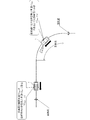
- FIG. 2 shows an example of a running state of a platoon with one following vehicle by the vehicle following running system.
- the leading vehicle 1 is traveling on a straight road after passing through a curved road
- the following vehicle 2 is traveling on a curved road.
- the turning running performance peculiar to the following vehicle 2 is predetermined from the viewpoint of suppressing at least one of deterioration of riding comfort, occurrence of slippage, and occurrence of load collapse.
- the turning performance of the following vehicle 2 is determined by the upper limit value of lateral acceleration (limit lateral acceleration) aylim and the upper limit value of yaw rate (limit yaw rate) r lim .
- an upper limit value (allowable maximum vehicle speed) V2 max is set for the speed of the following vehicle 2 according to the traveling path on which the following vehicle 2 travels.
- the permissible maximum vehicle speed V2 max is the speed (own vehicle speed) of the own vehicle when the actual lateral acceleration a y becomes the limit lateral acceleration a ylim in the following vehicle 2.
- the allowable maximum vehicle speed V2 max is the own vehicle speed when the actual yaw rate r becomes the limit yaw rate r lim in the following vehicle 2.
- the actual lateral acceleration and the actual yaw rate when the following vehicle 2 is traveling on a traveling road having a relatively large curvature have an increase in vehicle speed as compared with when traveling on a traveling road having a relatively small curvature. It tends to increase accordingly. Therefore, the actual lateral acceleration and the actual yaw rate when the following vehicle 2 is traveling on a large travel path of relatively curvature reaches the limit lateral acceleration a ylim and limit yaw rate r lim at a relatively low speed .. Therefore, the allowable maximum vehicle speed V2 max of the following vehicle 2 when traveling on a traveling road having a relatively large curvature is the following when traveling on a traveling road (including a straight road) having a relatively small curvature. It is smaller than the maximum allowable vehicle speed V2 max of the vehicle 2.
- the speed of the following vehicle 2 is prevented from exceeding the allowable maximum vehicle speed V2 max , and the actual lateral acceleration and the actual yaw rate of the following vehicle 2 are set to the limit values aylim and rlim or less determined by the turning performance. Suppress.
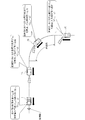
- FIG. 3 shows an example of a running state of a platoon in which there are three following vehicles by the vehicle following running system.
- the leading vehicle 1 and the first following vehicle 2A following the leading vehicle 1 are traveling on a straight road after passing through a curved road
- the second following vehicle 2B following the first following vehicle 2A is traveling on a curved road
- the third following vehicle 2C following the second following vehicle 2B is traveling on a straight road before entering the curved road.
- the following vehicles 2A to 2C each obtain the allowable maximum vehicle speed V2 max based on the turning driving performance at each traveling position, and transmit the information to the leading vehicle 1 by vehicle-to-vehicle communication.
- the smallest value among the allowable maximum vehicle speeds V2 max of the following vehicles 2A to 2C is set as the limiting vehicle speed V1 max.
- the speeds of the following vehicles 2A to 2C are prevented from exceeding the respective allowable maximum vehicle speeds V2 max , and the actual lateral accelerations and actual yaw rates of the following vehicles 2A to 2C are set to the limits determined by the turning performance. Suppress to values a ylim and r lim or less.
- the turning performances of the first to third following vehicles 2A to 2C may have different values.
- the allowable maximum vehicle speed V2 max in which the following vehicle 2 satisfies the turning performance of the own vehicle at each traveling position is obtained, and the leading vehicle 1 is set based on the allowable maximum vehicle speed V2 max of the following vehicle 2.
- the vehicle speed is controlled so that the vehicle speed does not exceed the vehicle speed limit V1 max of the vehicle.
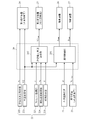
- FIG. 4 shows an example of a vehicle following traveling system mounted on a following vehicle.
- the vehicle-following traveling system mounted on the following vehicle 2 is mainly composed of a vehicle control device 20 including a microcomputer as a control unit, and is composed of an outside world recognition device 21, a vehicle state acquisition device 22, a reception device 23, and a first transmission device. 24, a second transmission device 25, a drive device 26, and a braking device 27 are provided.
- the outside world recognition device 21 is a device that recognizes an object existing in front of the own vehicle by, for example, a camera, a radar, a sonar, or the like. Specifically, the distance d between the own vehicle and the immediately preceding vehicle is measured. , Output that information.
- the vehicle state acquisition device 22 is a device for acquiring the vehicle state of the own vehicle, and includes a vehicle speed acquisition unit 221, a front-rear acceleration acquisition unit 222, a yaw rate acquisition unit 223, a lateral acceleration acquisition unit 224, and a steering angle acquisition unit 225. ..
- the vehicle speed acquisition unit 221 acquires the own vehicle speed V2 based on the vehicle speed pulse signal output from the vehicle speed sensor and the vehicle speed estimation result by the vehicle behavior control device represented by ABS (Anti-lock Braking System). , Outputs information about own vehicle speed V2.
- Longitudinal acceleration acquisition unit 222 acquires the longitudinal acceleration a x of the own vehicle by measurement using the longitudinal acceleration sensor of the in-vehicle, and outputs the information about the longitudinal acceleration a x. In longitudinal acceleration acquisition unit 222 may calculate the longitudinal acceleration a x on the basis of a change in vehicle speed V2 obtained by the vehicle speed acquisition unit 221.
- the yaw rate acquisition unit 223 acquires the yaw rate r of the own vehicle by measurement using, for example, an in-vehicle yaw rate sensor, and outputs information on the yaw rate r.
- the yaw rate acquisition unit 223 may calculate the yaw rate r by using the measured values of physical quantities such as the own vehicle speed V2 and the steering angle ⁇ , instead of the measurement using the yaw rate sensor.
- the lateral acceleration acquisition unit 224 acquires the lateral acceleration ay of the own vehicle by measurement using, for example, an in-vehicle lateral acceleration sensor, and outputs information on the lateral acceleration ay.
- the lateral acceleration acquisition unit 224 may calculate the lateral acceleration ay by using the measured values of physical quantities such as the own vehicle speed V2 and the steering angle ⁇ , instead of the measurement using the lateral acceleration sensor.
- the steering angle acquisition unit 225 acquires the steering angle ⁇ of the own vehicle by measurement using, for example, an in-vehicle steering angle sensor, and outputs information on the steering angle ⁇ .
- the receiving device 23 is a device that receives information on the speed (previous vehicle speed) Vf of the immediately preceding vehicle from the immediately preceding vehicle via vehicle-to-vehicle communication between the own vehicle and the immediately preceding vehicle in accordance with the instruction of the vehicle control device 20.
- the first transmission device 24 follows the output information of the vehicle speed acquisition unit 221 and the front-rear acceleration acquisition unit 222 with the own vehicle according to the instruction of the vehicle control device 20. It is a device that transmits to the immediately after vehicle via vehicle-to-vehicle communication with the immediately after vehicle (immediately after vehicle).
- the second transmission device 25 transmits information on the maximum allowable vehicle speed V2 max of the own vehicle calculated by the vehicle control device 20 according to the instruction of the vehicle control device 20 via inter-vehicle communication between the own vehicle and the leading vehicle 1. It is a device that transmits to the leading vehicle 1.
- the drive device 26 includes a drive source (engine, electric motor, or a combination thereof) that generates a drive force for the wheels of the own vehicle, and a drive controller that controls the drive force based on an acceleration command from the vehicle control device 20. Be prepared.
- a drive source engine, electric motor, or a combination thereof
- a drive controller that controls the drive force based on an acceleration command from the vehicle control device 20. Be prepared.
- the braking device 27 includes a braking mechanism (friction brake, drum brake, etc.) that applies a braking force to the wheels of the own vehicle, and a braking controller that controls the braking force based on a deceleration command from the vehicle control device 20.
- a braking mechanism forriction brake, drum brake, etc.
- the microcomputer of the vehicle control device 20 includes a processor such as a CPU (Central Processing Unit), a non-volatile memory such as a ROM (Read Only Memory), a volatile memory such as a RAM (Random Access Memory), and an input / output port. Is configured by bus connection. The same applies to various microcomputers described later.
- a processor such as a CPU (Central Processing Unit), a non-volatile memory such as a ROM (Read Only Memory), a volatile memory such as a RAM (Random Access Memory), and an input / output port.
- a processor such as a CPU (Central Processing Unit)
- a non-volatile memory such as a ROM (Read Only Memory)
- a volatile memory such as a RAM (Random Access Memory)
- Is configured by bus connection. The same applies to various microcomputers described later.
- the microcomputer of the vehicle control device 20 inputs various information output from the outside world recognition device 21, the vehicle state acquisition device 22, and the reception device 23, and calculates the result based on the various information in the second transmission device 25. Output to the drive device 26 and the braking device 27.
- the vehicle control device 20 has, as main functions, an inter-vehicle distance control unit 201 that keeps the inter-vehicle distance between the own vehicle and the immediately preceding vehicle at a target value and travels following the immediately preceding vehicle, and turning performance of the own vehicle at each traveling position. It has two functions of the allowable maximum vehicle speed calculation unit 202, which obtains the allowable maximum vehicle speed V2 max that satisfies the condition.
- each function of the vehicle control device 20 is realized by the processor reading the control program from the non-volatile memory into the volatile memory and executing the control program in the microcomputer. However, it does not exclude that a part or all of the functions of the vehicle control device 20 are realized by the hardware configuration. The same applies to various vehicle control devices described later.
- the inter-vehicle distance control unit 201 outputs an acceleration command value A com as an acceleration command to the drive device 26 of the own vehicle in order to keep the inter-vehicle distance between the own vehicle and the immediately preceding vehicle at the target value in platooning, and outputs the acceleration command value A com to the braking device 27.
- the deceleration command value D com is output as the deceleration command of.
- the target value of the inter-vehicle distance may be a variable value as well as a constant value. That is, a variable distance may be used as the target value of the inter-vehicle distance as the traveling state changes, for example, the target value of the inter-vehicle distance is increased as the vehicle speed increases.
- the inter-vehicle distance control unit 201 obtains an acceleration command value A com according to the following mathematical formula (1), for example.
- a com a xf + Kx ⁇ ⁇ x + Kv ⁇ ⁇ v ... (1)
- Equation (1) a xf is a longitudinal acceleration immediately before the vehicle obtained based on the output information of the receiving apparatus 23, at the time of acceleration immediately before the vehicle speed V f satisfies increases given as a positive value, immediately before the vehicle speed V f Is given as a negative value during deceleration.
- Kx and Kv are positive constant gains and are control constants stored in the non-volatile memory of the microcomputer.
- Vehicle control unit 201 when is positive acceleration command value A com calculated in accordance with Equation (1), and outputs an acceleration command of the acceleration command value A com to drive 26.
- the calculation formula of the acceleration command value A com in the inter-vehicle distance control unit 201 is not limited to the mathematical formula (1).
- the inter-vehicle distance control unit 201 processes and uses, for example, a mathematical formula including a differential term and an integral term , information on the front-rear acceleration a xf of the immediately preceding vehicle and the immediately preceding vehicle speed V f , or a formula that does not use these, and the like. It can be adopted as appropriate according to the above.
- Maximum allowable vehicle velocity calculating unit 202 based on the limit lateral acceleration a ylim or critical yaw r lim defined by turning performance of the following vehicle 2, the curvature ⁇ 2 of the traveling path of the following vehicle 2 is traveling, the Calculate the maximum allowable vehicle speed V2 max.
- Limit lateral acceleration a ylim and limit yaw rate r lim can be memorized as a fixed value in the non-volatile memory of the microcomputer, also a configuration that can be any value by a switch operation or the like by the vehicle user be able to.
- the limit lateral acceleration aylim or the limit yaw rate r lim is specified for the purpose of suppressing the occurrence of slip
- the limit lateral acceleration aylim or the limit yaw rate r lim is variably set according to the road surface condition of the traveling road. You may be able to do it.
- limit lateral acceleration a ylim or critical yaw rate r lim is defined for the purpose of suppressing the occurrence of collapsing is the limit lateral acceleration a ylim or critical yaw rate r lim depending on load capacity and stacking height It may be possible to make a variable setting.
- V2 max is according to Equation (2) below, or calculated the limit lateral acceleration a ylim as the square root of the value obtained by dividing the curvature .kappa.2, or according to the following equation (3), limits the yaw rate r lim Is calculated as the value divided by the curvature ⁇ 2.
- V2 max (a ylim / ⁇ 2 ) 1/2 ...
- V2 max r lim / ⁇ 2... (3)
- Maximum allowed vehicle speed calculating section 202 instead of using a curvature ⁇ 2 of the traveling path of the following vehicle 2 is traveling, by using the yaw rate r or the lateral acceleration a y obtained at the traveling position of the following vehicle 2 maximum allowable vehicle velocity V2 max can be calculated.
- the allowable maximum vehicle speed V2 max is calculated as a value obtained by dividing the limit lateral acceleration ampere by the yaw rate r according to the following formula (4), or the lateral acceleration according to the following formula (5). It can be calculated as a value obtained by dividing a y by the limit yaw rate r lim.
- V2 max aylim / r ... (4)
- V2 max a y / r lim ... (5)
- the method for calculating the allowable maximum vehicle speed V2 max in the vehicle control device 20 of the following vehicle 2 may be appropriately selected according to the specific configuration of the vehicle state acquisition device 22 of the following vehicle 2.
- the information regarding the allowable maximum vehicle speed V2 max calculated by the allowable maximum vehicle speed calculation unit 202 is output from the vehicle control device 20 to the second transmission device 25, and then transmitted from the second transmission device 25 to the leading vehicle 1.
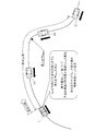
- FIG. 5 is a schematic view for explaining another example of the vehicle following traveling system of the following vehicle.
- the leading vehicle 1 is traveling on a straight road after passing through a curved road
- a following vehicle 2 is traveling on a straight road before entering the curved road.
- the allowable maximum vehicle speed V2 max that satisfies the turning traveling performance of the own vehicle on the straight road in which the following vehicle 2 is actually traveling is calculated.
- the allowable maximum vehicle speed V2 max that satisfies the turning performance of the own vehicle on the curved road to be driven by the following vehicle 2 is calculated.
- the vehicle control device 20 of the following vehicle 2 in Equation (2), together with substituting forward curvature .kappa.2 est replaced with curvature .kappa.2, by substituting the limit lateral acceleration a ylim, maximum allowable vehicle velocity V2 Calculate max.
- the allowable maximum vehicle speed V2 max is calculated by substituting the forward curvature ⁇ 2 est in place of the curvature ⁇ 2 and substituting the limit yaw rate r lim. Then, the vehicle control device 20 determines the allowable maximum vehicle speed V2 max calculated based on the forward curvature ⁇ 2 est and the turning performance of the own vehicle, and the turning performance of the own vehicle at the traveling position where the own vehicle is actually traveling.
- the vehicle control device 20 transmits information regarding the smaller allowable maximum vehicle speed V2 max to the leading vehicle 1.
- the leading vehicle 1 sets the limit vehicle speed V1 max of its own vehicle, the smaller allowable maximum vehicle speed V2 max is used.
- the forward curvature ⁇ 2 est can be estimated based on the outside world information recognized by the outside world recognition device 21. For example, when the outside world recognition device 21 is configured to be able to recognize the road marking line (white line) by image processing the camera image, the forward curvature ⁇ 2 est can be estimated from the recognized road marking line. Further, when the outside world recognition device 21 can acquire the relative position and the relative angle in addition to the inter-vehicle distance d between the own vehicle and the immediately preceding vehicle by the camera image processing, the traveling of the immediately preceding vehicle is performed from these acquired data. The forward curvature ⁇ 2 est can be estimated based on the curve interpolated as the locus.
- a straight line extending in the front-rear direction of the own vehicle and a straight line extending in the front-rear direction of the immediately preceding vehicle are specified on the quadric plane, and the curve is changed between the own vehicle and the immediately preceding vehicle while in contact with these two straight lines.
- the forward curvature ⁇ 2 est can be estimated based on the curves connecting without passing through points.
- the forward curvature ⁇ 2 est can be estimated by specifying the road shape of the forward traveling path from the map information. For example, when the following vehicle 2 can acquire the position of the own vehicle by GPS (Global Positioning System), a locator, or the like, the map information corresponding to the acquired position of the own vehicle is read out from the map information database to obtain the road shape of the front traveling path. It can be specified and the forward curvature ⁇ 2 est can be estimated.
- GPS Global Positioning System
- the forward curvature ⁇ 2 est can be estimated by acquiring the history of the vehicle state of the immediately preceding vehicle. For example, the physical quantities related to the vehicle condition (front-rear acceleration a x , lateral acceleration a y , yaw rate r, vehicle speed V2, etc.) acquired by the vehicle state acquisition device 22 of the immediately preceding vehicle are received by the receiving device 23 of the immediately preceding vehicle, and these physical quantities are used.
- the traveling locus of the immediately preceding vehicle can be estimated by dead reckoning using the integrated value.
- the vehicle can estimate the forward curvature ⁇ 2 est based on the estimated traveling locus.
- the immediately preceding vehicle when the immediately preceding vehicle is configured to acquire the own vehicle position and be able to transmit, the immediately following vehicle estimates the traveling locus based on the history of the own vehicle position of the immediately preceding vehicle, and based on this estimated traveling locus, The forward curvature ⁇ 2 est can be estimated.
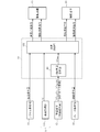
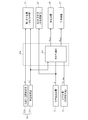
- FIG. 6 shows an example of a vehicle following traveling system mounted on the leading vehicle.
- the vehicle-following traveling system mounted on the leading vehicle 1 is mainly composed of a vehicle control device 10 including a microcomputer as a control unit, and has a vehicle state acquisition device 11, a reception device 12, an accelerator operation unit 13, and a brake operation unit 14. , A drive device 15 and a braking device 16.
- the vehicle state acquisition device 11 has a vehicle speed acquisition unit 111. Since the vehicle speed acquisition unit 111 has the same configuration as the vehicle speed acquisition unit 221 of the following vehicle 2, the description thereof will be omitted.
- the receiving device 12 receives information on the allowable maximum vehicle speeds V2 max (1), ..., V2 max (n) from each following vehicle 2 by vehicle-to-vehicle communication between the own vehicle and the following vehicle 2, and is a vehicle control unit. It is a device that outputs to.
- n is an integer (natural number) of 1 or more indicating the identification number of the following vehicle 2, and is assigned in ascending order in the order following the leading vehicle 1 by, for example, inter-vehicle communication.
- the accelerator operation unit 13 is a mechanism (for example, an accelerator pedal) for inputting an acceleration operation amount for the vehicle user to accelerate the own vehicle, detects an acceleration operation amount (for example, an accelerator opening degree), and outputs the information. Therefore, an acceleration manipulated variable sensor (not shown) is provided.
- the acceleration operation amount is a positive value in which the vehicle speed increases as the acceleration operation amount increases.
- the brake operation unit 14 is a mechanism (for example, a brake pedal) for inputting a braking operation amount for the vehicle user to decelerate the own vehicle, detects a braking operation amount (for example, a brake depression amount), and outputs the information. Therefore, a braking operation amount sensor (not shown) is provided.
- the braking operation amount is a positive value in which the vehicle speed decreases as the braking operation amount increases.
- the drive device 15 includes a drive source (engine, electric motor, or a combination thereof) that generates a drive force for the wheels of the own vehicle, and a drive controller that controls the drive force based on a control command output from the vehicle control device 10. , Equipped with.
- the control commands output from the vehicle control device 10 to the drive device 15 include a normal acceleration command and a limited acceleration command.
- the braking device 16 includes a braking mechanism (friction brake, drum brake, etc.) that applies a braking force to the wheels of the own vehicle, and a braking controller that controls the braking force based on a control command output from the vehicle control device 10. ..
- the control commands output from the vehicle control device 10 to the braking device 16 include a normal deceleration command and a forced deceleration command.
- the microcomputer of the vehicle control device 10 inputs various information output from the vehicle speed acquisition unit 111, the reception device 12, the accelerator operation unit 13, and the brake operation unit 14, and uses the result of calculation based on the various information as a control command. Output to the drive device 15 and the braking device 16.
- the vehicle control device 10 has two main functions, a limited vehicle speed setting unit 101 and a vehicle speed control unit 102.
- the limit vehicle speed setting unit 101 acquires the allowable maximum vehicle speed V2 max (1), ..., V2 max (n) (where n is a natural number) of the following vehicle 2 from the output information of the receiving device 12, and the allowable maximum vehicle speed V2.
- the limit vehicle speed V1 max is set based on max (1), ..., V2 max (n). Specifically, when there is only one following vehicle 2, the maximum allowable vehicle speed V2 max (1) is set to the limited vehicle speed V1 max. Alternatively, when there are a plurality of following vehicles 2, the smallest value among the allowable maximum vehicle speeds V2 max (1), ..., V2 max (n) (where n is a natural number of 2 or more) is set as the limit vehicle speed V1 max. do.
- the vehicle speed control unit 102 acquires the vehicle speed V1, the acceleration operation amount, and the braking operation amount from the output information of the vehicle speed acquisition unit 111, the accelerator operation unit 13, and the brake operation unit 14, and obtains the acceleration operation amount, the vehicle speed V1, and the limit vehicle speed V1.
- the control command generated based on max and the braking operation amount is output to the driving device 15 and the braking device 16. As a result, the vehicle speed control unit 102 controls the vehicle speed.
- the vehicle speed control unit 102 is basically a control command that outputs a normal acceleration command generated based on the acceleration operation amount accompanying the acceleration request of the vehicle user to the drive device 15. However, when the vehicle speed V1 exceeds the predetermined vehicle speed V1d, which is lower than the limit vehicle speed V1 max , the vehicle speed control unit 102 reduces the acceleration operation amount in order to limit the acceleration of the vehicle. A limit acceleration command is generated based on the amount, and this limit acceleration command is used as a control command to be output to the drive device 15. Specifically, when the own vehicle speed V1 is higher than the predetermined vehicle speed V1d in the range of the limited vehicle speed V1 max or less, the vehicle speed control unit 102 reduces the acceleration operation amount in the range in which the own vehicle can accelerate.
- the vehicle speed control unit 102 reduces the acceleration operation amount to a value (for example, zero) at which the vehicle does not substantially accelerate.
- the vehicle control device 10 has a predetermined vehicle speed according to the magnitude of the acceleration operation amount so that the predetermined vehicle speed V1d moves away from the limited vehicle speed V1 max as the acceleration operation amount increases (that is, as the front-rear acceleration increases).
- V1d may be set variably. Further, the vehicle control device 10 limits even when the own vehicle speed V1 exceeds the predetermined vehicle speed V1d when the acceleration operation amount is not input or when the acceleration operation amount is not a value indicating the acceleration request of the vehicle user.
- the output of the acceleration command can be omitted.
- the vehicle speed control unit 102 basically outputs a normal deceleration command generated based on the braking operation amount accompanying the braking request of the vehicle user to the braking device 16. However, when the vehicle speed V1 exceeds the limit vehicle speed V1 max , the vehicle speed control unit 102 issues a forced deceleration command for forcibly decelerating the vehicle in order to reduce the vehicle speed V1 to the limit vehicle speed V1 max or less. , A control command to be output to the braking device 16.
- the braking operation amount when the forced deceleration command is output may be a fixed value or may be variably set according to the excess amount of the own vehicle speed V1 with respect to the limited vehicle speed V1 max.
- the vehicle user's braking request is generated, that is, the braking operation amount acquired from the output information of the brake operation unit 14 in the vehicle control device 10 is determined by the vehicle user.
- a situation is assumed in which the value indicates a braking request.
- the vehicle speed control unit 102 predicts that the deceleration change of the own vehicle will be larger when braking according to the normal deceleration command than when braking according to the forced deceleration command, the vehicle speed control unit 102 issues the normal deceleration command to the braking device. It is a control command to be output to 16.
- the vehicle speed control unit 102 predicts that the deceleration change of the own vehicle will be smaller when braking according to the normal deceleration command than when braking according to the forced deceleration command, the vehicle speed control unit 102 will continue to issue the forced deceleration command to the braking device 16. It is a control command to be output to.
- the magnitude of the deceleration change when braking according to the forced deceleration command and the deceleration change when braking according to the normal deceleration command can be predicted as follows.
- the vehicle speed control unit 102 can predict the magnitude of the deceleration change by comparing the braking operation amount when outputting the forced deceleration command with the braking operation amount acquired from the output information of the brake operation unit 14. can.
- the vehicle speed control unit 102 determines that the deceleration change when braking according to the forced deceleration command and the deceleration change when braking according to the normal deceleration command are the same, either the forced deceleration command or the normal deceleration command is issued. It may be a control command.
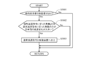
- FIG. 7 shows an excerpt of an example of a process that realizes the allowable maximum vehicle speed calculation unit 202 among the control processes that are repeatedly executed when the ignition switch is turned on in the vehicle control device of the following vehicle.
- step S1001 the vehicle control device 20 of the following vehicle 2 calculates the allowable maximum vehicle speed V2 max that satisfies the turning performance of the own vehicle.
- V2 max a specific calculation method of the allowable maximum vehicle speed V2 max , refer to the above description regarding the vehicle follow-up traveling system of the following vehicle 2 and another example thereof.
- step S1002 the vehicle control device 20 of the following vehicle 2 instructs the second transmission device 25 to transmit the calculated information on the allowable maximum vehicle speed V2 max from the second transmission device 25 to the leading vehicle 1.
- FIG. 8 shows an excerpt of an example of a process for realizing the limited vehicle speed setting unit 101 and the vehicle speed control unit 102 among the control processes repeatedly executed when the ignition switch is turned on in the vehicle control device of the leading vehicle. ..
- step S2001 the vehicle control device 10 of the leading vehicle 1 instructs the receiving device 12, and the receiving device 12 is instructed to the maximum allowable vehicle speed V2 max (1), ..., V2 max (n) of the following vehicle 2. Receive information about (natural numbers).
- step S2002 the vehicle control device 10 of the leading vehicle 1 acquires the allowable maximum vehicle speed of the following vehicle 2 from the output information of the receiving device 12 V2 max (1), ..., V2 max (n) (where n is a natural number). Based on, the limit vehicle speed V1 max of the own vehicle is set.
- step S2003 the vehicle control device 10 of the leading vehicle 1 determines whether or not the own vehicle speed V1 is larger than the limited vehicle speed V1 max. Then, when the vehicle control device 10 of the leading vehicle 1 determines that the own vehicle speed V1 is larger than the limited vehicle speed V1 max (YES), the process proceeds to step S2004. On the other hand, if the vehicle control device 10 of the leading vehicle 1 determines that the own vehicle speed V1 is equal to or less than the limit vehicle speed V1 max (NO), the process proceeds to step S2007.
- step S2004 the vehicle control device 10 of the leading vehicle 1 outputs a limit acceleration command to the drive device 15.
- the limited acceleration command is generated based on the corrected acceleration operation amount obtained by reducing the acceleration operation amount accompanying the acceleration request of the vehicle user to a value at which the own vehicle does not substantially accelerate.
- step S2005 the vehicle control device 10 of the leading vehicle 1 outputs a forced deceleration command to the braking device 16.
- the vehicle control device 10 of the leading vehicle 1 determines the suitability of the forced deceleration command. The specific processing content of the suitability judgment of the forced deceleration command will be described later.
- step S2007 the vehicle control device 10 of the leading vehicle 1 determines whether or not the own vehicle speed V1 is higher than the predetermined vehicle speed V1d. Then, when the vehicle control device 10 of the leading vehicle 1 determines that the own vehicle speed V1 is higher than the predetermined vehicle speed V1d (YES), the process proceeds to step S2008. On the other hand, when the vehicle control device 10 of the leading vehicle 1 determines that the own vehicle speed V1 is equal to or less than the predetermined vehicle speed V1d (NO), the control process is terminated without limiting the own vehicle speed.
- step S2008 the vehicle control device 10 of the leading vehicle 1 outputs a limit acceleration command to the drive device 15.
- the limit acceleration command output in this step is different from the limit acceleration command in step S2004, and as described above, after correction, the acceleration operation amount accompanying the acceleration request of the vehicle user is reduced within the range in which the own vehicle can accelerate. It is generated based on the acceleration operation amount.
- FIG. 9 is a subroutine showing an example of determining the suitability of the forced deceleration command in step S2006 among the control processes of FIG. 8 performed by the vehicle control device of the leading vehicle.
- step S3001 the vehicle control device 10 of the leading vehicle 1 determines whether or not there is a braking request from the vehicle user. As described above, the presence or absence of the braking request of the vehicle user can be determined based on the value of the braking operation amount acquired from the output information of the brake operation unit 14.
- step S3002 it is determined whether or not the deceleration change of the own vehicle is larger when the vehicle control device 10 of the leading vehicle 1 brakes according to the normal deceleration command than when braking according to the forced deceleration command.
- the vehicle control device 10 of the leading vehicle 1 determines that the deceleration change of the own vehicle is larger when braking according to the normal deceleration command than when braking according to the forced deceleration command (YES)
- the forced deceleration command is issued. Judge that the output is not appropriate. Then, the process proceeds to step S3003.
- step S3003 is omitted and the present subroutine is terminated.
- step S3003 the vehicle control device 10 of the leading vehicle 1 generates a normal deceleration command based on the braking operation amount acquired from the output information of the brake operation unit 14, and controls the normal deceleration command instead of the forced deceleration command. It is output to the braking device 16 as a command.
- the allowable maximum vehicle speed V2 max that satisfies the turning performance of the own vehicle is obtained in the following vehicle 2, and the allowable maximum transmitted from the following vehicle 2 in the leading vehicle 1 is obtained.
- the limited vehicle speed V1 max of the own vehicle is obtained based on the vehicle speed V2 max.
- the leading vehicle 1 controls the vehicle speed so that the own vehicle speed V1 does not exceed the limited vehicle speed V1 max.
- FIG. 10 shows an example of a running state of a platoon in which there are three following vehicles by the vehicle following running system.
- the first following vehicle 2A, the second following vehicle 2B, and the third following vehicle 2C are sequentially connected to the leading vehicle 1 in a non-mechanical manner, and each of the following vehicles 2A to 2C follows the immediately preceding vehicle. I'm running.
- the following vehicles 2A to 2C each satisfy the turning performance of the own vehicle on the traveling road on which the own vehicle is actually traveling or on the traveling road on which the own vehicle is about to travel.
- the maximum allowable vehicle speed V2 max was calculated.
- the following vehicles 2A to 2C are in the traveling path of the platoon section from the leading vehicle 1 to the rearmost third following vehicle 3C in the traveling road (already traveling road) in which the leading vehicle 1 has already traveled. Finds the maximum permissible vehicle speed V2 max that satisfies those turning performances for each following vehicle.
- the leading vehicle 1 calculates and sequentially stores the curvature of the traveling road, and determines the maximum curvature (maximum curvature) ⁇ max on the traveling road in the platoon section of the existing traveling road. Then, the leading vehicle 1 obtains the allowable maximum vehicle speed V2 max for each following vehicle based on the maximum curvature ⁇ max and the turning performance of the following vehicles 2A to 2C. Then, the leading vehicle 1 sets the smallest value among the obtained maximum allowable vehicle speeds V2 max of the following vehicles 2A to 2C as the limited vehicle speed V1 max of the own vehicle, and the vehicle speed so that the own vehicle speed does not exceed the limited vehicle speed V1 max. Take control.
- the leading vehicle 1 is obtained based on the maximum curvature ⁇ max and the turning performance of one following vehicle 2A.
- the maximum allowable vehicle speed V2 max is set to the limited vehicle speed V1 max of the own vehicle.
- FIG. 11 shows an example of a vehicle following traveling system mounted on a following vehicle.
- the vehicle-following traveling system mounted on the following vehicle 2 is mainly composed of the vehicle control device 20a, and includes an outside world recognition device 21, a vehicle state acquisition device 22a, a reception device 23, a first transmission device 24, and a second transmission device 25. It includes a driving device 26 and a braking device 27.
- the vehicle control device 20a includes a microcomputer as a control unit and has the above-mentioned inter-vehicle distance control unit 201 as a main function, but does not have a maximum allowable vehicle speed calculation unit 202. Further, the vehicle control device 20a instructs the second transmission device 25 to transmit the information regarding the inter-vehicle distance d output from the outside world recognition device 21 to the leading vehicle 1 instead of the information regarding the allowable maximum vehicle speed V2 max.
- the vehicle state acquisition device 22a has a front-rear acceleration acquisition unit 222 and a vehicle speed acquisition unit 221 necessary for vehicle speed control, and has a yaw rate acquisition unit 223, a lateral acceleration acquisition unit 224, and a steering angle necessary for calculating the allowable maximum vehicle speed V2 max.
- the acquisition unit 225 is omitted.
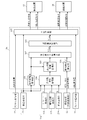
- FIG. 12 shows an example of a vehicle following traveling system mounted on the leading vehicle.
- the vehicle-following traveling system mounted on the leading vehicle 1 is mainly composed of a vehicle control device 10a including a microcomputer as a control unit, and has a vehicle state acquisition device 11a, a reception device 12, an accelerator operation unit 13, and a brake operation unit 14. , A drive device 15 and a braking device 16.
- the vehicle state acquisition device 11a has a yaw rate acquisition unit 112, a lateral acceleration acquisition unit 113, and a steering angle acquisition unit 114 in addition to the vehicle speed acquisition unit 111.
- the yaw rate acquisition unit 112, the lateral acceleration acquisition unit 113, and the steering angle acquisition unit 114 are the same as the yaw rate acquisition unit 223, the lateral acceleration acquisition unit 224, and the steering angle acquisition unit 225 in the following vehicle 2 according to the first embodiment, respectively. Since it is the composition of, the explanation is omitted.
- the microcomputer of the vehicle control device 10a inputs various information output from the vehicle state acquisition device 11a, the reception device 12, the accelerator operation unit 13, and the brake operation unit 14, and controls the result of calculation based on the various information. Is output to the drive device 15 and the braking device 16.
- the vehicle control device 10a has, as a main function, a function for acquiring information necessary for setting the limited vehicle speed V1 max , in addition to the above-mentioned two functions of the limited vehicle speed setting unit 101 and the vehicle speed control unit 102. ..
- This function is composed of five parts: a mileage acquisition unit 103, a mileage information acquisition unit 104, an existing mileage information storage unit 105, a platoon length estimation unit 106, and an allowable maximum vehicle speed calculation unit 107.
- the mileage acquisition unit 103 acquires the own vehicle speed V1 from the output information of the vehicle speed acquisition unit 111, and acquires the mileage B of the own vehicle based on the own vehicle speed V1.
- the mileage B of the leading vehicle 1 can be obtained by integrating the multiplication value obtained by multiplying the own vehicle speed V1 acquired at each control cycle in the microcomputer of the vehicle control device 10a by the control cycle time.
- the travel path information acquisition unit 104 acquires a physical quantity indicating the vehicle state at the actual travel position of the own vehicle from the output information of the vehicle state acquisition device 11a, and based on this physical quantity, the travel path at the actual travel position of the own vehicle. Acquire information (roadway information) related to the shape of.
- the curvature ⁇ 1 of the travel path at the travel position of the own vehicle can be mentioned.
- the curvature ⁇ 1 is calculated by appropriately substituting the own vehicle speed V1, the lateral acceleration ay , the yaw rate r, and the steering angle ⁇ into various relational expressions indicating the basic motion characteristics of the vehicle.
- the various relational expressions showing the basic motion characteristics of the vehicle are the same as the various relational expressions used when calculating the curvature ⁇ 2 of the traveling path on which the following vehicle 2 is traveling in the first embodiment. Is omitted.
- Various relational expressions used for calculating the curvature ⁇ 1 in the leading vehicle 1 may be appropriately selected depending on what kind of acquisition unit is included in the vehicle state acquisition device 11a of the leading vehicle 1.
- the platoon section is relatively short, for example, when the following vehicle 2 is one, or when the leading vehicle 1 is traveling at a constant speed on the traveling path of the platoon section, the position of the trailing following vehicle 2 is started.
- the change in vehicle speed of the leading vehicle 1 is small up to the position of the leading vehicle 1, and it can be considered that the vehicle speed of the leading vehicle 1 is constant on the traveling path of the platoon section.
- each value of yaw rate, lateral acceleration or rudder angle acquired in the traveling path of the platoon section indirectly indicates the magnitude relationship of the curvature ⁇ 1 in the traveling path of the platoon section.
- the yaw rate r or the lateral acceleration ay acquired by the vehicle state acquisition unit 11a is used instead of the curvature ⁇ 1. It may be acquired as it is as travel path information.
- the existing mileage information storage unit 105 acquires the mileage B and the mileage information, the mileage B is associated with the mileage information and stored in the volatile memory of the microcomputer as the existing mileage information.
- the existing travel path information is information regarding the shape of the travel path on which the leading vehicle 1 has already traveled.
- the platoon length estimation unit 106 corresponds to the length of the platoon section based on the inter-vehicle distances d (1), ..., D (n) (where n is a natural number) acquired from the output information of the receiving device 12.
- Estimate the formation length C is specifically estimated based on the total value of the inter-vehicle distances d (1), ..., D (n) (where n is a natural number), but the vehicle length of the following vehicle 2 is known. If, this vehicle length may be added.
- the allowable maximum vehicle speed calculation unit 107 includes the mileage B acquired by the mileage acquisition unit 103, the existing mileage information stored in the existing mileage information storage unit 105, and the platoon estimated by the platoon length estimation unit 106. Based on the length C, the maximum allowable vehicle speed V2 max is set as follows.
- the maximum allowed vehicle speed calculator 107 subtracts the convoy length C from the travel distance B of the subject vehicle, identifies the travel distance B end The leading vehicle 1 corresponding to the traveling position of the end vehicle convoy.
- the maximum allowable vehicle velocity calculating unit 107 refers to the already-travel path information, to determine the maximum curvature kappa max in the travel path of the row interval from the curvature ⁇ 1 from the travel distance B to the travel distance B end The.
- the existing road information having a mileage of less than Bend among the existing road information stored in the volatile memory or the like may be deleted.
- the allowable maximum vehicle speed calculation unit 107 calculates the allowable maximum vehicle speed V2 max for each of the following vehicles 2 based on the maximum curvature ⁇ max and the turning performance of the following vehicle 2.
- the allowable maximum vehicle speed V2 max can be calculated by replacing the curvature ⁇ 2 of the above equation (2) or the equation (3) with the maximum curvature ⁇ max. That is, the allowable maximum vehicle speed V2 max is calculated as the square root value of the value obtained by dividing the limit lateral acceleration ampere by the maximum curvature ⁇ max , or as the value obtained by dividing the limit yaw rate r lim by the maximum curvature ⁇ max. NS.
- one of the plurality of following vehicles 2 is used without calculating the allowable maximum vehicle speed V2 max for all of the plurality of following vehicles 2.
- the maximum allowable vehicle speed V2 max may be calculated for the vehicle.
- the allowable maximum vehicle speed calculation unit 107 refers to the existing traveling road information and refers to the platoon section.
- the maximum value of the yaw rate r or the lateral acceleration ay on the road is determined. This is because it is considered that when the yaw rate r or the lateral acceleration ay in the traveling path of the platoon section becomes the maximum value, the curvature in the traveling path of the platoon section becomes the maximum curvature ⁇ max .
- the allowable maximum vehicle speed calculation unit 107 substitutes the maximum value of the yaw rate r into the mathematical formula (4) or substitutes the maximum value of the lateral acceleration ay into the mathematical formula (5), and substitutes the maximum allowable value for each of the following vehicles 2. Calculate the vehicle speed V2 max.
- the limit vehicle speed setting unit 101 limits the vehicle speed V1 based on the allowable maximum vehicle speed V2 max (1), ..., V2 max (n) (where n is a natural number) of the following vehicle 2 calculated by the allowable maximum vehicle speed calculation unit 107.
- Set max. Specifically, the limit vehicle speed setting unit 101 sets the allowable maximum vehicle speed V2 max (1) to the limit vehicle speed V1 max if there is one following vehicle 2, and the allowable maximum vehicle speed if there are a plurality of following vehicles 2.
- the smallest value among V2 max (1), ..., V2 max (n) (where n is a natural number of 2 or more) is set as the limit vehicle speed V1 max.
- the vehicle speed control unit 102 acquires the vehicle speed V1, the acceleration operation amount, and the braking operation amount from the output information of the vehicle speed acquisition unit 111, the accelerator operation unit 13, and the brake operation unit 14, and obtains the acceleration operation amount, the vehicle speed V1, and the limit vehicle speed V1.
- the control command generated based on max and the braking operation amount is output to the driving device 15 and the braking device 16.
- the vehicle speed control unit 102 controls the vehicle speed. Since the specific contents of the other vehicle speed control unit 102 are the same as those in the first embodiment, the description thereof will be omitted.
- FIG. 13 shows an excerpt of an example of a main part of the control process that is repeatedly executed when the ignition switch is turned on in the vehicle control device of the following vehicle, excluding the process that realizes the inter-vehicle distance control unit 201.
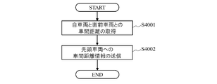
- step S4001 the vehicle control device 20a of the following vehicle 2 acquires the inter-vehicle distance d between the own vehicle and the immediately preceding vehicle from the output information of the outside world recognition device 21.
- step S4002 the vehicle control device 20a of the following vehicle 2 instructs the second transmission device 25 to transmit information on the inter-vehicle distance d from the second transmission device 25 to the leading vehicle 1.
- FIG. 14 shows an excerpt of an example of a process that realizes the above-mentioned main function among the control processes that are repeatedly executed when the ignition switch is turned on in the vehicle control device of the leading vehicle.
- step S5001 the vehicle control device 10a of the leading vehicle 1 acquires the own vehicle speed V1 from the output information of the vehicle speed acquisition unit 111, and calculates the mileage B of the own vehicle based on the own vehicle speed V1.
- step S5002 the vehicle control device 10a of the leading vehicle 1 acquires a physical quantity indicating the vehicle state at the actual traveling position of the own vehicle from the output information of the vehicle state acquisition device 11a, and based on this physical quantity, travel path information (for example, Obtain the curvature ⁇ 1).
- travel path information for example, Obtain the curvature ⁇ 1.
- step S5003 the vehicle control device 10a of the leading vehicle 1 associates the travel path information acquired in step S5002 with the travel distance B acquired in step S5001 and stores it in the volatile memory of the microcomputer as existing travel path information.
- step S5004 the vehicle control device 10a of the leading vehicle 1 has the platoon length based on the inter-vehicle distances d (1), ..., D (n) (where n is a natural number) acquired from the output information of the receiving device 12. Estimate C. Note that step S5004 may be executed before step S5003.
- step S5005 the vehicle control device 10a of the leading vehicle 1 is based on the mileage B acquired in step S5001, the platoon length C estimated in step S5002, and the existing lane information stored in step S5003. Calculate the maximum allowable vehicle speed V2 max. Since the specific calculation method of the allowable maximum vehicle speed V2 max is as described in the above-mentioned allowable maximum vehicle speed calculation unit 107, the description thereof will be omitted.
- step S5006 the vehicle control device 10a of the leading vehicle 1 is based on the maximum allowable vehicle speed V2 max (1), ..., V2 max (n) (where n is a natural number) of the following vehicle 2 calculated in step S5005. Set the vehicle speed limit V1 max.
- steps S5007 to S5012 the same processing as in steps S2003 to S2008 is executed, so the description thereof will be omitted.
- the following vehicle 2 measures the inter-vehicle distance d between the own vehicle and the immediately preceding vehicle, but the measurement mode of the inter-vehicle distance d is this. Not limited to.
- the leading vehicle 1 measures the inter-vehicle distance d between the own vehicle and the immediately following vehicle using a rear recognition device capable of recognizing an object existing behind the own vehicle. can do. As a result, the following vehicle 2 does not need to transmit the information regarding the inter-vehicle distance d to the leading vehicle 1.
- the leading vehicle 1 measures the inter-vehicle distance d between the own vehicle and the immediately following vehicle using the rear recognition device, and the following vehicle 2 is the leading vehicle 1.
- the rear recognition device it is possible to measure the inter-vehicle distance d between the own vehicle and the immediately following vehicle. As a result, the last car in the platoon does not need to transmit the information regarding the inter-vehicle distance d to the first car 1.
- the platoon length is estimated by the vehicle control device 10a of the leading vehicle 1.
- Part 106 can be omitted.
- the vehicle control device 10a of the leading vehicle 1 sets the platoon length C as a known fixed value stored in advance in the non-volatile memory of the microcomputer in the allowable maximum vehicle speed calculation unit 107, and sets the allowable maximum vehicle speed V2. Calculate max.
- the leading vehicle 1 has the maximum allowable vehicle speed based on the maximum curvature ⁇ max on the traveling road in the platoon section of the existing traveling road and the turning traveling performance of the following vehicle 2.
- V2 max is calculated.
- the leading vehicle 1 sets the limited vehicle speed V1 max of the own vehicle based on the allowable maximum vehicle speed V2 max of the following vehicle 2, and controls the vehicle speed so that the own vehicle speed does not exceed the limited vehicle speed V1 max.
- the maximum allowable vehicle speed V2 max of the following vehicle 2 calculated by the maximum allowable vehicle speed calculation unit 107 is input to the limited vehicle speed setting unit 101, and then the limited vehicle speed V1 max is calculated.
- the limited vehicle speed V1 max may be directly selected based on the existing road information stored in the existing road information storage unit 105.
- the leading vehicle 1 sets the limited vehicle speed V1 max of the own vehicle based on the allowable maximum vehicle speed V2 max of the following vehicle 2, so that the own vehicle speed does not exceed the limited vehicle speed V1 max.
- the vehicle speed was controlled. Instead, the leading vehicle 1 may simply control the vehicle speed so that the own vehicle does not accelerate when the following vehicle 2 enters the curved road.
- the following vehicle 2 limits the vehicle speed to the leading vehicle 1 when it is determined that the own vehicle has entered a curved road based on the output information of the yaw rate acquisition unit 223, the lateral acceleration acquisition unit 224, or the steering angle acquisition unit 225. Sends a limit request signal requesting that it be done.
- the leading vehicle 1 controls the vehicle speed so that the own vehicle does not accelerate in response to the restriction request signal.
- the leading vehicle 1 controls the vehicle speed so that the own vehicle does not accelerate in response to the restriction request signal.
- the braking request of the vehicle user during the output of the forced deceleration command is performed. It may be interrupt processing executed according to.
- the function of performing vehicle-to-vehicle communication is subdivided into three for convenience of function explanation, but the receiving device 23, the first transmitting device 24, and the second transmitting device 25 are combined into one. It may be configured as a communication device.
- the vehicle speed control unit 102 selects whether to output a normal acceleration command or a limited acceleration command, and whether to output a normal deceleration command or a forced deceleration command. I was making a choice.
- the drive controller of the drive device 15 selects either the normal acceleration command from the accelerator operation unit 13 or the limit acceleration command from the vehicle speed control unit 102, and the braking controller of the braking device 16 selects the normal deceleration from the brake operation unit 14. Either a command or a forced deceleration command from the vehicle speed control unit 102 may be selected.
- External world recognition device 25 ... Second transmission device , 202 ... Allowable maximum vehicle speed calculation unit, 221 ... Vehicle speed acquisition unit, 223 ... Yaw rate acquisition unit, 224 ... Lateral acceleration acquisition unit, 225 ... Steering angle acquisition unit, ay ... Lateral acceleration, aylim ... Limit lateral acceleration, r ... Yaw rate, r lim ... Limit yaw rate, V1 ... Own vehicle speed of leading vehicle, V1d ... Predetermined vehicle speed, V1 max ... Limited vehicle speed, V2 max ... Allowable maximum vehicle speed of following vehicle, ⁇ 1 ... Curvature at running position of leading vehicle, ⁇ max ... Maximum curvature on the track of the platoon section, ⁇ 2 ... Curvature at the traveling position of the following vehicle, ⁇ 2 est ... Forward curvature of the following vehicle
Landscapes
- Engineering & Computer Science (AREA)
- Transportation (AREA)
- Mechanical Engineering (AREA)
- Automation & Control Theory (AREA)
- Physics & Mathematics (AREA)
- General Physics & Mathematics (AREA)
- Radar, Positioning & Navigation (AREA)
- Aviation & Aerospace Engineering (AREA)
- Remote Sensing (AREA)
- Combustion & Propulsion (AREA)
- Chemical & Material Sciences (AREA)
- Mathematical Physics (AREA)
- Computer Networks & Wireless Communication (AREA)
- Signal Processing (AREA)
- Control Of Driving Devices And Active Controlling Of Vehicle (AREA)
- Controls For Constant Speed Travelling (AREA)
- Regulating Braking Force (AREA)
Abstract
Description
(車両追従走行システムの概要)
図1~図3を参照して、第1実施形態に係る車両追従走行システムの概要について説明する。車両追従走行システムは、先頭車両に1台以上の後続車両を非機械的に順次連結することで、各後続車両を先行する直前の車両(直前車両)に追従して走行させるためのシステムである。なお、本明細書における車両は、道路上を走行する自動車である。
図4は、後続車両に搭載される車両追従走行システムの一例を示す。後続車両2に搭載される車両追従走行システムは、コントロール部としてのマイクロコンピュータを含む車両制御装置20を中心の構成として、外界認識装置21、車両状態取得装置22、受信装置23、第1送信装置24、第2送信装置25、駆動装置26及び制動装置27を備える。
Acom=axf+Kx×Δx+Kv×Δv…(1)
V2max=(aylim/κ2)1/2 …(2)
V2max=rlim/κ2 …(3)
V2max=aylim/r …(4)
V2max=ay/rlim …(5)
図5は、後続車両の車両追従走行システムの別例を説明するための模式図である。図5において、先頭車両1が曲線路を通過した後の直線路を走行中であり、ある後続車両2が曲線路に進入する前の直線路を走行している。前述の車両追従走行システムによれば、後続車両2が、実際に走行している直線路において自車両の旋回走行性能を満たす許容最大車速V2maxを算出していた。しかし本例では、図5に示すように、後続車両2が、これから走行する曲線路において自車両の旋回走行性能を満たす許容最大車速V2maxを算出する。すなわち、後続車両2が、これから走行する曲線路の曲率(前方曲率)κ2estと自車両の旋回走行性能とに基づいて許容最大車速V2max(=u2)を算出する。そして先頭車両1が自車両の制限車速V1maxを設定する際には、その許容最大車速V2max(=u2)を用いる。これにより、後続車両2が曲線路に進入する前に先頭車両1の制限速度V1maxを低く設定できるようにして、後続車両2がこれから走行する曲線路で発生する横加速度をより確実に抑制する。
図6は、先頭車両に搭載される車両追従走行システムの一例を示す。先頭車両1に搭載される車両追従走行システムは、コントロール部としてのマイクロコンピュータを含む車両制御装置10を中心の構成として、車両状態取得装置11、受信装置12、アクセル操作部13、ブレーキ操作部14、駆動装置15及び制動装置16を備える。車両状態取得装置11は車速取得部111を有している。なお、車速取得部111は、後続車両2の車速取得部221と同様の構成であるので、その説明を割愛する。
図7は、後続車両の車両制御装置において、イグニッションスイッチのオン操作を契機として繰り返し実行される制御処理のうち、許容最大車速算出部202を実現する処理の一例を抜粋して示す。
図8は、先頭車両の車両制御装置において、イグニッションスイッチのオン操作を契機として繰り返し実行される制御処理のうち、制限車速設定部101及び車速制御部102を実現する処理の一例を抜粋して示す。
図9は、先頭車両の車両制御装置において行われる図8の制御処理のうち、ステップS2006における強制減速指令の適否判断の一例を示すサブルーチンである。
(車両追従走行システムの概要)
図10を参照して、第2実施形態に係る車両追従走行システムの概要について説明する。なお、本実施形態では、第1実施形態と異なる点について説明するので、第1実施形態と同様の構成については同一の符号を付して、その説明を割愛ないし簡略化する。
図11は、後続車両に搭載される車両追従走行システムの一例を示す。後続車両2に搭載される車両追従走行システムは、車両制御装置20aを中心の構成として、外界認識装置21、車両状態取得装置22a、受信装置23、第1送信装置24、第2送信装置25、駆動装置26及び制動装置27を備える。
図12は、先頭車両に搭載される車両追従走行システムの一例を示す。先頭車両1に搭載される車両追従走行システムは、コントロール部としてのマイクロコンピュータを含む車両制御装置10aを中心の構成として、車両状態取得装置11a、受信装置12、アクセル操作部13、ブレーキ操作部14、駆動装置15及び制動装置16を備える。車両状態取得装置11aは、車速取得部111に加えて、ヨーレート取得部112、横加速度取得部113及び舵角取得部114を有している。
図13は、後続車両の車両制御装置において、イグニッションスイッチのオン操作を契機として繰り返し実行される制御処理のうち、車間制御部201を実現する処理を除く主要部の一例を抜粋して示す。
図14は、先頭車両の車両制御装置において、イグニッションスイッチのオン操作を契機として繰り返し実行される制御処理のうち前述の主要機能を実現する処理の一例を抜粋して示す。
尚、上述の通り、図12では許容最大車速算出部107で算出された後続車両2の許容最大車速V2maxを制限車速設定部101に入力してから制限車速V1maxを算出していたが、既走行路情報記憶部105に記憶された既走行路情報をもとに制限車速V1maxをダイレクトに選択してもよい。
Claims (14)
- 先頭車両に後続車両を非機械的に順次連結して、各後続車両を先行する直前の車両に追従して走行させる車両追従走行システムの前記先頭車両に搭載され、入力した情報に基づいて演算した結果を制御指令として制動装置又は駆動装置へ出力するコントロール部を備えた車両制御装置であって、
前記コントロール部は、
前記後続車両の旋回走行性能を満たす前記後続車両の許容最大車速に基づいて、前記先頭車両の速度を制限するための制限車速を求め、
前記先頭車両の速度が前記制限車速を超えないように、前記制動装置及び前記駆動装置へ前記制御指令を出力する、
車両制御装置。 - 請求項1に記載の車両制御装置であって、
前記許容最大車速は前記後続車両において求められ、
前記コントロール部は、前記許容最大車速を前記後続車両から取得する、
車両制御装置。 - 請求項2に記載の車両制御装置であって、
前記コントロール部は、
前記先頭車両の速度が、前記制限車速より低い所定車速を超えた場合、前記駆動装置へ出力する前記制御指令を、前記先頭車両の加速を制限する制限加速指令とする、
車両制御装置。 - 請求項2に記載の車両制御装置であって、
前記コントロール部は、
前記先頭車両の速度が前記制限車速より高い場合、前記制動装置へ出力する前記制御指令を、前記先頭車両を強制的に減速させる強制減速指令とする、
車両制御装置。 - 請求項4に記載の車両制御装置であって、
前記コントロール部は、
前記強制減速指令を出力している間に前記車両使用者の制動要求に伴う制動操作量が入力されたときに、前記強制減速指令に従って制動したときよりも前記車両使用者の制動要求に従って制動したときの方が前記先行車両の減速変化が大きくなると判断した場合には、前記制動装置へ出力する前記制御指令を、前記制動操作量に基づいて生成された減速指令とする、
車両制御装置。 - 請求項2に記載の車両制御装置であって、
前記後続車両の旋回走行性能は、前記後続車両における横加速度の許容上限値である、
車両制御装置。 - 請求項2に記載の車両制御装置であって、
前記後続車両の旋回走行性能は、前記後続車両におけるヨーレートの許容上限値である、
車両制御装置。 - 請求項2に記載の車両制御装置であって、
前記許容最大車速は、前記後続車両の走行路の曲率に基づいて求められる、
車両制御装置。 - 請求項2に記載の車両制御装置であって、前記許容最大車速は、前記後続車両の旋回走行性能と、前記後続車両の旋回走行中の走行路の形状を示す物理量又は前記第1後続車両の旋回走行中の車両状態を示す物理量と、に基づいて求められる、
車両制御装置。 - 請求項2に記載の車両制御装置であって、
前記許容最大車速は、前記後続車両の旋回走行性能と、前記後続車両が走行すると予測される走行路の形状を示す物理量と、に基づいて求められる
車両制御装置。 - 請求項1に記載の車両制御装置であって、
前記コントロール部は、
前記後続車両の旋回走行性能と、前記先頭車両が既に走行した走行路の形状に関する情報と、に基づいて前記制限車速を設定する、
車両制御装置。 - 請求項1に記載の車両制御装置であって、
前記後続車両が複数台で構成され、
前記コントロール部は、
前記後続車両のそれぞれについて求められた前記許容最大車速のうち最も小さい値を前記制限車速に設定する、
車両制御装置。 - 先頭車両に後続車両を非機械的に順次連結して、各後続車両を先行する直前の車両に追従して走行させる車両追従走行システムの前記先頭車両の車両制御方法であって、
前記後続車両の旋回走行性能を満たす前記後続車両の許容最大車速に基づいて、前記先頭車両の速度を制限するための制限車速を求め、
前記先頭車両の速度が前記制限車速を超えないように、制動装置及び駆動装置を制御する、
車両制御方法。 - 先頭車両に後続車両を非機械的に順次連結して、各後続車両を先行する直前の車両に追従して走行させる車両追従走行システムであって、
前記先頭車両は、
コントロール部であって、
前記後続車両の旋回走行性能を満たす前記後続車両の許容最大車速に基づいて、前記先頭車両の速度を制限するための制限車速を求め、
前記先頭車両の速度が前記制限車速を超えないように、前記先頭車両の加減速度を制御するための制御指令を出力する、
コントロール部と、
前記制御指令に基づいて制動力を制御する制動装置と、
前記制御指令に基づいて駆動力を制御する駆動装置と、
を備える車両追従走行システム。
Priority Applications (4)
| Application Number | Priority Date | Filing Date | Title |
|---|---|---|---|
| US17/794,717 US12420792B2 (en) | 2020-01-23 | 2021-01-21 | Vehicle control apparatus, vehicle control method, and adaptive cruise control system |
| EP21743655.9A EP4095004B1 (en) | 2020-01-23 | 2021-01-21 | Vehicle control method, vehicle control system and convoy of vehicles |
| JP2021572792A JP7465286B2 (ja) | 2020-01-23 | 2021-01-21 | 車両制御装置、車両制御方法及び車両追従走行システム |
| CN202180010679.0A CN115023378A (zh) | 2020-01-23 | 2021-01-21 | 车辆控制装置、车辆控制方法以及车辆跟随行驶系统 |
Applications Claiming Priority (2)
| Application Number | Priority Date | Filing Date | Title |
|---|---|---|---|
| JP2020009097 | 2020-01-23 | ||
| JP2020-009097 | 2020-01-23 |
Publications (3)
| Publication Number | Publication Date |
|---|---|
| WO2021149768A1 true WO2021149768A1 (ja) | 2021-07-29 |
| WO2021149768A9 WO2021149768A9 (ja) | 2022-06-09 |
| WO2021149768A8 WO2021149768A8 (ja) | 2022-07-07 |
Family
ID=76992544
Family Applications (1)
| Application Number | Title | Priority Date | Filing Date |
|---|---|---|---|
| PCT/JP2021/002054 Ceased WO2021149768A1 (ja) | 2020-01-23 | 2021-01-21 | 車両制御装置、車両制御方法及び車両追従走行システム |
Country Status (5)
| Country | Link |
|---|---|
| US (1) | US12420792B2 (ja) |
| EP (1) | EP4095004B1 (ja) |
| JP (1) | JP7465286B2 (ja) |
| CN (1) | CN115023378A (ja) |
| WO (1) | WO2021149768A1 (ja) |
Cited By (2)
| Publication number | Priority date | Publication date | Assignee | Title |
|---|---|---|---|---|
| US20210284158A1 (en) * | 2020-03-12 | 2021-09-16 | Honda Motor Co., Ltd. | Information processing method |
| CN114013457A (zh) * | 2021-11-19 | 2022-02-08 | 长沙智能驾驶研究院有限公司 | 车辆控制方法、装置、设备及计算机存储介质 |
Families Citing this family (7)
| Publication number | Priority date | Publication date | Assignee | Title |
|---|---|---|---|---|
| FR3113479B1 (fr) * | 2020-08-24 | 2022-09-02 | Renault Sas | Procédé de gestion automatisée de la vitesse longitudinale d’un véhicule. |
| JP2022122302A (ja) * | 2021-02-10 | 2022-08-23 | ロベルト・ボッシュ・ゲゼルシャフト・ミト・ベシュレンクテル・ハフツング | 制御装置及び制御方法 |
| DE102021116468A1 (de) * | 2021-06-25 | 2022-12-29 | Ford Global Technologies, Llc | Verfahren zum Betrieb eines Fahrzeug-Platoons mit einer Mehrzahl von Kraftfahrzeugen |
| US20250136112A1 (en) * | 2021-09-14 | 2025-05-01 | University Of Washington | Safe occlusion-aware cooperative adaptive cruise control under environmental interference |
| US20230343223A1 (en) * | 2022-04-22 | 2023-10-26 | The Regents Of The University Of California | System and method for autonomously maneuvering vehicle nodes in a platoon |
| KR20240092690A (ko) * | 2022-12-14 | 2024-06-24 | 현대자동차주식회사 | 자율 주행 제어 장치 및 그 방법 |
| US12391282B2 (en) * | 2023-02-10 | 2025-08-19 | Pebble Mobility Inc. | Systems and methods for virtually towing an autonomous electric-powered trailer |
Citations (3)
| Publication number | Priority date | Publication date | Assignee | Title |
|---|---|---|---|---|
| JP2009056964A (ja) * | 2007-08-31 | 2009-03-19 | Toyota Motor Corp | 走行計画生成装置 |
| JP2010030525A (ja) * | 2008-07-30 | 2010-02-12 | Toyota Motor Corp | 走行支援装置 |
| JP2015020502A (ja) | 2013-07-17 | 2015-02-02 | 日産自動車株式会社 | 車両用走行制御装置 |
Family Cites Families (12)
| Publication number | Priority date | Publication date | Assignee | Title |
|---|---|---|---|---|
| JP4563619B2 (ja) * | 2001-06-28 | 2010-10-13 | 富士重工業株式会社 | 車両用運転支援装置 |
| JP4127245B2 (ja) * | 2004-06-07 | 2008-07-30 | 日産自動車株式会社 | 車両用制動力制御装置 |
| JP4277755B2 (ja) * | 2004-07-16 | 2009-06-10 | 日産自動車株式会社 | 車両用旋回走行制御装置 |
| DE102006039121A1 (de) * | 2006-04-03 | 2007-10-04 | Robert Bosch Gmbh | Deaktivierung einer Sicherheitsfunktion durch Bremsen |
| JP2009006828A (ja) * | 2007-06-27 | 2009-01-15 | Denso Corp | 車速制御装置及び車速制御プログラム |
| JP5760835B2 (ja) * | 2011-08-10 | 2015-08-12 | 株式会社デンソー | 走行支援装置及び走行支援システム |
| US10007271B2 (en) * | 2015-12-11 | 2018-06-26 | Avishtech, Llc | Autonomous vehicle towing system and method |
| EP4091894B1 (en) * | 2016-03-03 | 2024-11-06 | Volvo Truck Corporation | A vehicle with autonomous driving capability |
| JP6813433B2 (ja) | 2017-06-13 | 2021-01-13 | 日立オートモティブシステムズ株式会社 | 車両運動制御装置、車両運動制御方法および車両運動制御システム |
| CA3073666A1 (en) * | 2017-08-22 | 2019-02-28 | Nissan Motor Co., Ltd. | Method and device for generating target path for autonomous vehicle |
| JP7147524B2 (ja) * | 2018-12-07 | 2022-10-05 | トヨタ自動車株式会社 | 車両制御装置 |
| US20210041882A1 (en) * | 2019-08-09 | 2021-02-11 | Alberto Daniel Lacaze | Path Follower with Limited Steering Rate Controller |
-
2021
- 2021-01-21 US US17/794,717 patent/US12420792B2/en active Active
- 2021-01-21 EP EP21743655.9A patent/EP4095004B1/en active Active
- 2021-01-21 CN CN202180010679.0A patent/CN115023378A/zh active Pending
- 2021-01-21 JP JP2021572792A patent/JP7465286B2/ja active Active
- 2021-01-21 WO PCT/JP2021/002054 patent/WO2021149768A1/ja not_active Ceased
Patent Citations (3)
| Publication number | Priority date | Publication date | Assignee | Title |
|---|---|---|---|---|
| JP2009056964A (ja) * | 2007-08-31 | 2009-03-19 | Toyota Motor Corp | 走行計画生成装置 |
| JP2010030525A (ja) * | 2008-07-30 | 2010-02-12 | Toyota Motor Corp | 走行支援装置 |
| JP2015020502A (ja) | 2013-07-17 | 2015-02-02 | 日産自動車株式会社 | 車両用走行制御装置 |
Non-Patent Citations (1)
| Title |
|---|
| See also references of EP4095004A4 |
Cited By (2)
| Publication number | Priority date | Publication date | Assignee | Title |
|---|---|---|---|---|
| US20210284158A1 (en) * | 2020-03-12 | 2021-09-16 | Honda Motor Co., Ltd. | Information processing method |
| CN114013457A (zh) * | 2021-11-19 | 2022-02-08 | 长沙智能驾驶研究院有限公司 | 车辆控制方法、装置、设备及计算机存储介质 |
Also Published As
| Publication number | Publication date |
|---|---|
| JP7465286B2 (ja) | 2024-04-10 |
| EP4095004A1 (en) | 2022-11-30 |
| WO2021149768A9 (ja) | 2022-06-09 |
| EP4095004A4 (en) | 2023-07-19 |
| WO2021149768A8 (ja) | 2022-07-07 |
| JPWO2021149768A1 (ja) | 2021-07-29 |
| US12420792B2 (en) | 2025-09-23 |
| EP4095004B1 (en) | 2025-08-06 |
| CN115023378A (zh) | 2022-09-06 |
| US20230073287A1 (en) | 2023-03-09 |
Similar Documents
| Publication | Publication Date | Title |
|---|---|---|
| JP7465286B2 (ja) | 車両制御装置、車両制御方法及び車両追従走行システム | |
| CN112739586B (zh) | 车辆控制装置 | |
| JP6105439B2 (ja) | 減速度設定システム、方法およびプログラム | |
| US8073606B2 (en) | Vehicle control system | |
| US9969394B2 (en) | Distance regulating system, motor vehicle and computer program product | |
| JP2015219830A (ja) | 運転支援装置 | |
| JP3689065B2 (ja) | 車両用走行制御装置 | |
| JP2012228979A (ja) | 先行車追従走行装置 | |
| JP2021102368A (ja) | 車両制御装置 | |
| JP7397408B2 (ja) | 車両制御装置 | |
| KR20230073985A (ko) | 차량 정보 처리 장치, 차량 정보 처리 방법 및 비일시적 기억 매체 | |
| US20240375653A1 (en) | Control Device and Method for Controlling a Predictive Cruise Control | |
| JP2007168788A (ja) | 自動車の走行制御装置 | |
| JP7409204B2 (ja) | 車両制御装置 | |
| KR20230027545A (ko) | 자동차 및 그를 위한 가속도 제한 제어 방법 | |
| KR20230017797A (ko) | 적응형 순항 제어를 위한 가상 타깃을 갖는 운전자 보조 방법 | |
| JP2016078730A (ja) | 車両走行制御装置 | |
| CN116279419A (zh) | 车辆控制装置、车辆控制方法以及非临时性存储介质 | |
| JP2022021309A (ja) | 前方にあるカーブを通過する際に、エゴ・車両の車両運転手をサポートするための方法 | |
| CN119502900A (zh) | 用于控制至少部分自主的本机动车的方法 | |
| CN119773752A (zh) | 车道变更辅助装置 | |
| KR20250128377A (ko) | 적응형 속도 제어기를 작동하기 위한 방법 | |
| JP7651329B2 (ja) | 車両の運転支援システム及び情報処理装置 | |
| JP2025076093A (ja) | 車両の運転支援装置 | |
| US12447967B2 (en) | Vehicle control device, operation method of vehicle control device, and storage medium |
Legal Events
| Date | Code | Title | Description |
|---|---|---|---|
| 121 | Ep: the epo has been informed by wipo that ep was designated in this application |
Ref document number: 21743655 Country of ref document: EP Kind code of ref document: A1 |
|
| ENP | Entry into the national phase |
Ref document number: 2021572792 Country of ref document: JP Kind code of ref document: A |
|
| NENP | Non-entry into the national phase |
Ref country code: DE |
|
| ENP | Entry into the national phase |
Ref document number: 2021743655 Country of ref document: EP Effective date: 20220823 |
|
| WWG | Wipo information: grant in national office |
Ref document number: 2021743655 Country of ref document: EP |
|
| WWG | Wipo information: grant in national office |
Ref document number: 17794717 Country of ref document: US |