WO2021152842A1 - 逆止弁 - Google Patents
逆止弁 Download PDFInfo
- Publication number
- WO2021152842A1 WO2021152842A1 PCT/JP2020/003755 JP2020003755W WO2021152842A1 WO 2021152842 A1 WO2021152842 A1 WO 2021152842A1 JP 2020003755 W JP2020003755 W JP 2020003755W WO 2021152842 A1 WO2021152842 A1 WO 2021152842A1
- Authority
- WO
- WIPO (PCT)
- Prior art keywords
- valve
- flow path
- valve body
- check valve
- center line
- Prior art date
- Legal status (The legal status is an assumption and is not a legal conclusion. Google has not performed a legal analysis and makes no representation as to the accuracy of the status listed.)
- Ceased
Links
Images





Classifications
-
- F—MECHANICAL ENGINEERING; LIGHTING; HEATING; WEAPONS; BLASTING
- F16—ENGINEERING ELEMENTS AND UNITS; GENERAL MEASURES FOR PRODUCING AND MAINTAINING EFFECTIVE FUNCTIONING OF MACHINES OR INSTALLATIONS; THERMAL INSULATION IN GENERAL
- F16K—VALVES; TAPS; COCKS; ACTUATING-FLOATS; DEVICES FOR VENTING OR AERATING
- F16K15/00—Check valves
- F16K15/02—Check valves with guided rigid valve members
- F16K15/06—Check valves with guided rigid valve members with guided stems
- F16K15/063—Check valves with guided rigid valve members with guided stems the valve being loaded by a spring
-
- F—MECHANICAL ENGINEERING; LIGHTING; HEATING; WEAPONS; BLASTING
- F16—ENGINEERING ELEMENTS AND UNITS; GENERAL MEASURES FOR PRODUCING AND MAINTAINING EFFECTIVE FUNCTIONING OF MACHINES OR INSTALLATIONS; THERMAL INSULATION IN GENERAL
- F16K—VALVES; TAPS; COCKS; ACTUATING-FLOATS; DEVICES FOR VENTING OR AERATING
- F16K1/00—Lift valves or globe valves, i.e. cut-off apparatus with closure members having at least a component of their opening and closing motion perpendicular to the closing faces
- F16K1/32—Details
- F16K1/34—Cutting-off parts, e.g. valve members, seats
- F16K1/36—Valve members
-
- F—MECHANICAL ENGINEERING; LIGHTING; HEATING; WEAPONS; BLASTING
- F16—ENGINEERING ELEMENTS AND UNITS; GENERAL MEASURES FOR PRODUCING AND MAINTAINING EFFECTIVE FUNCTIONING OF MACHINES OR INSTALLATIONS; THERMAL INSULATION IN GENERAL
- F16K—VALVES; TAPS; COCKS; ACTUATING-FLOATS; DEVICES FOR VENTING OR AERATING
- F16K1/00—Lift valves or globe valves, i.e. cut-off apparatus with closure members having at least a component of their opening and closing motion perpendicular to the closing faces
- F16K1/32—Details
- F16K1/34—Cutting-off parts, e.g. valve members, seats
- F16K1/42—Valve seats
-
- F—MECHANICAL ENGINEERING; LIGHTING; HEATING; WEAPONS; BLASTING
- F16—ENGINEERING ELEMENTS AND UNITS; GENERAL MEASURES FOR PRODUCING AND MAINTAINING EFFECTIVE FUNCTIONING OF MACHINES OR INSTALLATIONS; THERMAL INSULATION IN GENERAL
- F16K—VALVES; TAPS; COCKS; ACTUATING-FLOATS; DEVICES FOR VENTING OR AERATING
- F16K27/00—Construction of housing; Use of materials therefor
- F16K27/02—Construction of housing; Use of materials therefor of lift valves
- F16K27/0209—Check valves or pivoted valves
Definitions
- Check valves that allow fluid in pipes to pass in one direction are known.
- the lift-type check valve has a structure in which the valve body linearly reciprocates in the direction of approaching or separating from the valve seat, so that a quick closing operation is possible.
- the Smolenski-type lift-type check valve can suitably suppress the occurrence of water hammer by providing a spring body.
- Patent Document 1 discloses a Y-shaped check valve which is a straight pipe joint type diagonal lift type.
- the check valve includes a valve body and a spring body that urges the valve seat side in a direction of pushing down the valve body.
- the valve body of this check valve is lifted diagonally upward by the fluid flowing in the forward direction with respect to the linear direction connecting the inflow port and the outflow port to open, and when the fluid tries to flow in the opposite direction, it is a spring body.
- the valve body moves diagonally downward and closes.
- the check valve disclosed in Patent Document 1 has the convenience of lifting the valve body diagonally upward with respect to the linear direction connecting the inflow port and the outflow port when the fluid flows in the forward direction.
- the fluid pressure in the flow path tends to be non-uniform. For this reason, a vortex may be generated in a part of the flow path, and the pressure loss may be large.
- the present invention is a straight pipe joint type diagonal lift type check valve, and linearly reciprocates between the valve seat, the closed state in close contact with the valve seat, and the open state separated from the valve seat. It is provided with a possible moving body, a primary flow path located upstream of the moving body, and a secondary flow path located downstream of the moving body, and the moving body is supported by a valve seat in a closed state.
- the valve seat includes the valve body and the valve shaft extending from the valve body, and the valve seat has a center line in a cross section including the center line of the connection flow path connecting the connecting portions connected to other pipe bodies to be connected.
- a check valve is provided, which is characterized in that it is formed so as to straddle.
- the vertical direction may be defined and described, but this is set for convenience in order to explain the relative relationship of the components, and is used at the time of manufacturing or using the product according to the present invention. It does not specify the direction of. Ideally, the vertical upward direction is upward and the vertical downward direction is downward, but this does not limit the installation state of the check valve. “Upper and lower” related to the check valve refers to the direction in which the moving body is separated from the valve body in the direction perpendicular to the connection flow path direction to which the check valve is connected, and is close to the valve body. The direction to do is downward.
- the check valve 1 has a valve seat 12a, a moving body 2 capable of linearly reciprocating between a closed state in close contact with the valve seat 12a and an open state separated from the valve seat 12a, and upstream of the moving body 2. It includes a primary flow path (inflow path 12c) located on the side and a secondary flow path (outflow path 12d) located on the downstream side of the moving body 2.
- the moving body 2 includes a valve body 6 supported by a valve seat in a closed state, and a valve shaft 7 extending from the valve body 6.
- the valve seat 12a straddles the center line CL in a cross section including the center line CL of the connecting flow path that extends linearly including the primary flow path (inflow path 12c) and the secondary flow path (outflow path 12d). It is characterized in that it is formed in such a manner.
- the "straight pipe joint type” is a pipe joint connected to another pipe, and has an outflow direction as an extension of the inflow direction.
- the “diagonal lift type” is a type in which the valve body operates diagonally with respect to a straight line connecting the inflow direction and the outflow direction, and the valve body is lifted by a fluid.
- the connecting portions to be connected to other pipes are the flange portions 13 and 14 and are flanges, but the present invention is not limited to such a configuration and may be connected to other pipes. For example, it may be a portion by a ferrule connection or a portion by a screw connection.
- valve seat 12a straddles the center line CL
- the center line CL passes through the opening defined by the valve seat 12a, and a part of the valve seat 12a is below the center line CL. It means that the other part is above the center line CL.
- the valve seat 12a may be formed so as to straddle the center line at any of the cross sections including the center line CL.
- valve seat 12a is formed so as to straddle the center line CL of the connecting flow path, the valve body is not straddled and is biased to one side.
- 6 When 6 is opened, it becomes easy for the fluid to flow linearly, and it is possible to suppress the occurrence of turbulent flow (vortex flow). Therefore, the pressure loss of the check valve 1 that occurs when the fluid flows can be reduced.
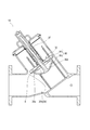
- FIG. 3 is a vertical cross-sectional view showing an open state of the check valve 1 according to the first embodiment
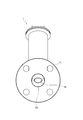
- FIG. 4 is a side view of the check valve 1 according to the first embodiment as viewed from the inflow path 12c side
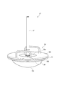
- FIG. 5 is a diagram mainly explaining the dynamic pressure distribution by omitting the valve body upper portion 6b, the packing 8, the valve box 12, the spring body 20, etc., and showing the configuration of the check valve 1 in a simplified manner. be.
- the check valve 1 is a straight pipe joint type diagonal lift type as described above, and the moving body 2 including the valve body 6 linearly approaches or separates from the valve seat 12a. It swings back and forth.
- the check valve 1 includes an inflow path 12c and an outflow path 12d having the same center line CL.
- the moving body 2 swings back and forth in a direction inclined obliquely with respect to the center line CL, specifically, in a direction inclined toward the outflow path 12d side.
- the fluid whose backflow is regulated by the check valve 1 is a liquid such as water or a gas such as air.
- the check valve 1 of the present embodiment is a so-called Smolenski type. Therefore, due to the urging force of the spring body 20, the check valve 1 abuts on the valve seat 12a at the moment when the flow of the fluid turns to the backflow flowing from the secondary side to the primary side, and quickly flows through the flow path. Close. As a result, the check valve 1 can prevent backflow, suppress the occurrence of water hammer, and increase the certainty of the closed state (water stoppage).
- the check valve 1 is not limited to the configuration in which the spring body 20 is provided and the valve body 6 is pressed against the valve seat 12a. For example, the valve body 6 is pressed against the valve seat 12a only by the own weight of the moving body 2 or by the load applied from the damper mechanism by the own weight of the moving body 2, the valve shaft 7, and the guide cylinder 4 described later. May be good.
- the valve box 12 is integrally formed with a substantially linearly extending joint portion 9 forming an inflow passage 12c and an outflow passage 12d by a lost wax manufacturing method, and is branched from the joint portion 9. Crossing.
- the valve box 12 and the valve shaft 7 described later extend in a direction intersecting the flow path directions of the primary flow path (inflow path 12c) and the secondary flow path (outflow path 12d) so as to be inclined toward the outflow path 12d. is doing.
- a flange portion 13 is integrally formed on the upstream side (primary side) and a flange portion 14 is integrally formed on the downstream side (secondary side), and bolts and nuts are integrally formed with respect to pipes (not shown). It is fixed using a fastener (not shown) such as.
- a flat suction pipe (not shown) connected to a suction pump (not shown) is attached to the inflow path 12c side of the valve box 12 (joint portion 9) according to the present embodiment.
- a mounting base 15 is formed.
- the mounting base 15 is formed with a pressure reducing port 15a that penetrates to the inside of the valve box 12 on the primary flow path side.
- the operator can make the upstream side of the valve body 6 negative pressure and fill it with the fluid. If a configuration in which a pressure sensor is attached to the pressure reducing port 15a is adopted, the operator confirms the pressure state inside the valve box 12 and confirms whether the inside of the valve box 12 is filled with the fluid. You can also.
- a guide cap 3 described later is detachably attached to the end of the portion of the valve box 12 extending in the direction intersecting the center line CL of the inflow path 12c and the outflow path 12d.
- the valve seat 12a is a cross-sectional view including the center line CL of the connecting flow path connecting the connecting portions (flange portions 13 and 14) connected to other pipes to be connected. , It is formed so as to straddle the center line CL. Further, the valve seat 12a is formed so that a part of the inner wall of the valve box 12 protrudes toward the flow path side over the entire circumference (so as to narrow the inflow path 12c).
- the seat surface of the valve seat 12a is formed in an annular shape and extends perpendicularly to the reciprocating direction of the moving body 2. That is, the valve seat 12a extends in a direction intersecting the flow path directions of the inflow path 12c and the outflow path 12d and the extending direction of the valve shaft 7 and the valve box 12.
- An annular groove 12h is formed on the outer circumference of the valve seat 12a.
- the annular groove 12h is formed by being recessed on the inflow path 12c side (the side away from the moving body 2) with respect to the seat surface of the valve seat 12a.
- the annular groove 12h limits the area of the valve seat 12a that the valve body 6 of the moving body 2 comes into contact with, so that the valve body 6 can easily come into close contact with the valve seat 12a.
- the valve seat 12a extends in a direction intersecting the flow path directions of the primary flow path (inflow path 12c) and the secondary flow path (outflow path 12d) and the extension direction of the valve shaft 7.
- a downstream overhanging portion 12f overhanging the center line CL side is provided below the inner wall surface on the downstream side of the valve seat 12a forming the secondary flow path (outflow passage 12d).
- overhanging to the center line CL side means that the inner wall surface of the joint portion 9 is overhanging to the center line CL side from the main wall surface (inner wall surface linearly continuous from the flange portions 13 and 14). Point to. That is, as shown in FIG.
- the downstream overhanging portion is overhanging (from the main wall surface) even if it is continuously formed from the valve seat.
- the lower portion of the joint portion 9 defining the outflow path 12d is thickened, so that the inner wall surface of the thickened portion is on the center line CL side. It has a structure that overhangs. Then, the amount of overhang of the downstream overhanging portion 12f gradually decreases toward the downstream side.
- the cross-sectional area of the flow path on the downstream side of the valve seat 12a does not change rapidly locally.
- the downstream overhanging portion 12f is closer to the center line CL side of the flow path than the portion closer to the center line CL side in the valve seat 12a. It does not protrude into the area and is an extension of this area.
- the downstream overhanging portion 12f projects inward of the flow path so as to define the outer periphery of the annular groove 12h on the downstream side, and then gently expands toward the outer peripheral surface side toward the downstream side.
- the cross-sectional area of the flow path on the downstream side of the valve seat is rapidly expanded. Therefore, a vortex is generated due to the difference in the dynamic pressure of the fluid flowing into the extension portion on the downstream side.
- the flow path cross-sectional area in the vicinity of the valve seat 12a of the outflow passage 12d is constant or gradually changes toward the downstream side, so that the flow flows on the secondary side beyond the valve seat 12a. It is possible to suppress the generation of vortices due to the rapid expansion of the road cross-sectional area.
- an upstream overhanging portion 12i overhanging toward the center line is provided above the inner wall surface on the upstream side of the valve seat 12a forming the primary flow path (inflow path 12c). More specifically, the upstream side overhanging portion 12i projects diagonally downward toward the downstream side. Then, the amount of overhang of the upstream side overhanging portion 12i gradually increases toward the downstream side.
- the upstream side overhang portion 12i of the present embodiment is provided on the upstream side of the valve seat.
- the primary flow path is directed diagonally upward. Therefore, the fluid that goes downstream through the opening of the valve body meanders significantly.
- a part of the fluid flowing in from the inflow path 12c comes into contact with the upstream side overhanging portion 12i, so that the upstream side overhanging portion 12i can form a flow diagonally downward. .. Therefore, the fluid that needs to be directed diagonally upward in order to push up the valve body 6 by the opening of the valve seat 12a can flow linearly through the inflow path 12c and the outflow path 12d, and the pressure loss can be suppressed. ..
- the upstream side overhanging portion 12i does not overhang up to the center line CL.
- the upstream side overhanging portion 12i according to the present embodiment projects from the upper wall surface by 1/3 (including approximately 1/3) of the flow path width on the inflow side in the vertical cross section shown in FIG. According to the above configuration, as shown in FIG. 4, a part of the fluid can easily flow linearly from the inflow path 12c along the center line CL, and the pressure loss can be reduced.
- the moving body 2 reciprocates inside the valve box 12 to move the valve body 6 close to the valve seat 12a between the primary flow path and the secondary flow path, so that the valve body 2 is separated from the valve seat 12a according to the flow rate. This is to prevent backflow while adjusting the opening amount of 6.
- the moving body 2 is attached to a valve body 7 extending in the reciprocating direction, a valve body 6 provided at the lower end of the valve shaft 7, and a valve body 6 that abuts on the valve seat 12a in a closed state. It is mainly composed of a water stop portion (packing 8).
- valve shaft 7 is housed in the guide cylinder 4 described later, and reciprocates the moving body 2 so that the moving body 2 does not move in the direction perpendicular to the axial direction of the valve shaft 7. It is for moving.
- the valve shaft 7 is formed in a rod shape and extends continuously from the central portion of the upper surface of the valve body 6.
- valve body 6 and the valve shaft 7 are made of stainless steel, but can also be made of a corrosion-resistant synthetic resin material such as polyvinyl chloride.
- the spring body 20 mounted around the valve shaft 7 elastically urges the upper surface of the valve body 6 (valve body upper portion 6b).
- the valve body 6 includes a lower part 6a of the valve body and an upper part 6b of the valve body.
- the valve body upper portion 6b extends in a direction intersecting the flow path directions of the inflow path 12c and the outflow path 12d and the extending direction of the valve shaft 7 and the valve box 12.
- the valve body upper portion 6b has a collar 6c that extends radially from the valve body lower portion 6a with the valve shaft 7 as the center.
- the end of the valve body upper portion 6b itself is a collar 6c.
- the lower end of the collar 6c is below the center line CL when in the closed state shown in FIG. 3, and moves to a position above the center line CL at any position in the open state shown in FIG. do.
- the collar 6c moves to a position above the center line CL, so that the amount of fluid flowing linearly can be increased. can.
- the lower end of the packing 8 described later is located lower than the lower end of the collar 6c.
- the lower end portion of the collar 6c is located below the lower end portion of the packing 8. good.
- the lower end of the packing 8 is also located above the center line CL. The amount of fluid flowing linearly through the check valve 1 can be increased.
- the upper portion 6b of the valve body is in sliding contact with the inner wall 12b of the valve box 12 so that the lower end side of the moving body 2 does not move in the direction perpendicular to the axial direction of the valve shaft 7 when the moving body 2 reciprocates. By doing so, it has a function of guiding the movement. That is, when the valve body 6 is opened, the end portion of the upper portion 6b of the valve body on the inflow path 12c side is arranged so as to be slidable with the inner wall 12b of the valve box 12.
- the inner wall 12b of the valve box 12 with which the upper portion 6b of the valve body slides is not limited to a flat one, and a rib-shaped one such as a guide rib 12g protruding from the surroundings is also included in a part of the inner wall 12b. It shall be a wall.
- the upper portion 6b of the valve body is arranged so as to be slidable with the four guide ribs 12g protruding inside the valve box 12 and extending along the elongated direction of the valve box 12.
- the end portion of the valve body upper portion 6b on the inflow path 12c side is arranged so as to be slidable with the inner wall 12b of the valve box 12, so that the deflection of the valve body upper portion 6b is suppressed by the valve box 12. can do.
- valve body upper part 6b has a function as a washer that evenly supports the packing 8 in the surface direction with the valve body lower part 6a by pushing the upper surface from the nut 11.
- an insertion hole 6g through which the valve shaft 7 is inserted is formed so as to penetrate in the wall thickness direction.
- the valve body lower portion 6a includes a flat upper surface in which the valve shaft 7 is continuously formed in the central portion, and another surface formed in a partially spherical shape. More specifically, the valve body lower portion 6a has a partial spherical surface on the outer surface on the side facing the flow path. In particular, as shown in FIG. 4, the partial spherical surface of the lower portion 6a of the valve body is arranged at a position where the fluid flowing linearly from the inflow path 12c in the flow path direction abuts.
- valve body 6 valve body lower part 6a
- moving body 2 valve body 6
- the portion of the valve body lower part 6a The check valve 1 flows while the fluid is in contact with the spherical surface side. Therefore, the valve body 36 is less likely to interfere with the flow of the fluid, and can suppress the decrease in the speed of the fluid. Therefore, the fluid can be circulated with a low head loss (friction resistance).
- the lower part of the valve shaft 7, the lower part of the valve body 6a, and the upper part 6b of the valve body are configured by assembling separate members.
- the present invention is not limited to such a configuration, and if the packing 8 has flexibility and can be attached to the valve body 6 by deforming the packing 8, the lower valve body 6a and the upper valve body are not necessarily limited. 6b does not have to be composed of a separate member.
- the water stop portion (packing 8) is a member that is pressed by the valve body 6 (upper part 6b of the valve body) and the valve seat 12a in the closed state of the check valve 1 to stop the water in the valve seat 12a, and the lower part 6a of the valve body. It is arranged between the valve body upper portion 6b (flange 6c) and the valve body upper portion 6b (flange 6c).
- the packing 8 has a central hole penetrating in the thickness direction and is formed in an annular shape. Specifically, the packing 8 is arranged between the lower part 6a of the valve body and the upper part 6b of the valve body through the valve shaft 7 through the central hole of the packing 8. A part of the packing 8 is below the center line CL when it is in the closed state shown in FIG.
- any position in the open state is preferably a position when the valve body 6 is in the open state at a standard flow rate.
- this position is a position in which the check valve 1 (valve body 6) is open 70% (70% of the maximum opening degree of the check valve 1) with respect to the fully opened state. According to such a configuration, it is possible to prevent the packing 8 from obstructing the flow in the vicinity of the center line CL where the flow is the fastest at a standard flow rate, and it is possible to suppress an increase in pressure loss.
- the check valve 1 further includes a nut 11 that presses the valve body upper portion 6b from the other side (upper side) toward the valve body lower portion 6a side.
- the nut 11 has a friction ring that can be elastically deformed, and has a locking function.
- the nut 11 only needs to have a loosening prevention function, and is not limited to a nut 11 having a friction ring.
- it may be configured to consist of a double nut (not shown).
- one of the double nuts may have a wedge-shaped protrusion, and a concave groove may be formed in a corresponding shape so that the other nut accepts the protrusion.
- the guide cap 3 is detachably attached to the valve box 12 to seal the upper side of the valve body 6 and guide the reciprocating movement of the moving body 2. ..
- the guide cap 3 is composed of a guide cylinder 4 and a disk-shaped top plate portion 5 integrally formed at the upper end of the guide cylinder 4.
- the top plate portion 5 has a ferrule flange 5e shown in FIG. 2 at the end edge, and the gasket 16 is sandwiched between the ferrule flange 5e and the ferrule flange 12e formed at the upper end portion of the valve box 12. It is detachably fastened with a ferrule joint (not shown).
- a guide cylinder 4 is erected diagonally downward (on the primary flow path side) at substantially the center of the top plate portion 5.
- the guide cylinder 4 guides the sliding of the valve shaft 7 of the valve body 6 on its inner surface, extends diagonally downward from the top plate portion 5 on the valve seat 12a side, and the valve body 6 reciprocates.
- the valve shaft 7 connected to the valve body 6 is guided so as to be possible.
- FIG. 5 is an explanatory diagram showing the dynamic pressure distribution in the flow path when the fluid flows through the check valve 1 according to the first embodiment, and has a flow velocity of about 4 m / s on the inflow side and a flow rate of about 4800 L / min ( It is a figure which shows the flow of fluid, and the dynamic pressure distribution at a valve opening degree 50%).
- the darker the color the higher the dot density
- the higher the dynamic pressure the dynamic pressure.
- the mainstream having a high dynamic pressure does not go toward the bottom side of the flow path and is substantially in the flow path direction. It extends parallel to. It can be seen that the vortex W induced by the mainstream does not erode to the center side of the flow path, and its range is small. Therefore, the diffusion and separation of the fluid were small, the head loss was about 2.8 m, and the pressure loss could be suppressed to a small value.
- FIG. 6 is a vertical cross-sectional view showing an open state of the check valve 1X according to the second embodiment.
- the configuration of the check valve 1X, which is common to the check valve 1 according to the first embodiment, will not be described.
- the check valve 1X includes a moving body 32.
- the moving body 32 includes a valve shaft 37 and a valve body 36 integrally formed with a lower end portion of the valve shaft 37.
- the valve body 36 is configured to include a valve body lower part 36a and a valve body upper part 36b.
- the valve body lower portion 36a is formed in a partially spherical shape having a hollow portion 36d. More specifically, the valve body lower portion 36a has a partial spherical surface on the outer surface on the side facing the flow path, has a shape symmetrical to the center line CL, and has a check valve 1 It is arranged inside.
- the valve body lower portion 36a has a hollow portion 36d to improve the responsiveness to a change in the flow rate, and is formed in a partially spherical shape to suppress the flow resistance.
- the pressure loss can be reduced.
- the valve body lower portion 36a is provided with an annular small diameter portion 36h at a portion that abuts on the valve body upper portion 36b.
- An opening 36i connected to the hollow portion 36d is formed in the small diameter portion 36h.
- the packing 8 is fitted in the recess 36e formed between the outer peripheral side of the small diameter portion 36h, the upper portion 36b of the valve body, and the lower portion 36a of the valve body. More specifically, the recess 36e has an L-shaped cross section formed by the lower surface of the upper portion 36b of the valve body and the upper surface of a part of the lower portion 36a of the valve body continuous from the peripheral surface of the small diameter portion 36h. It is formed by overlapping.
- FIG. 7 is a vertical cross-sectional view showing the open state of the check valve 1Y according to the third embodiment
- FIG. 8 is a perspective view showing the moving body 52 according to the third embodiment.
- the configuration of the check valve 1Y that is common to the check valve 1 according to the first embodiment or the check valve 1X according to the second embodiment will not be described.
- the guide cap related to the check valve 1Y has the same size as that of the first embodiment and the second embodiment, and therefore the description thereof will be omitted.
- the check valve 1Y mainly includes a moving body 52 and a valve box 62 for accommodating the moving body 52.
- the moving body 52 is mainly composed of a round bar-shaped valve shaft 57 extending in the reciprocating direction, a valve body 56 provided at the lower end of the valve shaft 57, and a packing 8 attached to the valve body 56. It is configured in.
- the valve body 56 is composed of a valve body lower portion 56a integrally formed at the lower end (primary flow path side) of the valve shaft 57 and a valve body upper portion 56b attached to the valve body lower portion 56a. There is.
- the valve body lower portion 56a has an outer surface formed in a partially spherical shape, and is cut off in parallel with the reciprocating direction of the moving body 52, and two flat surface portions 56f extending in parallel with each other are centered in the axial direction. It is held at a position shifted by 180 degrees.
- the area of the edge portion 56k which will be described later, can be increased as compared with the one without the flat surface portion 56f. Therefore, the load of the fluid that pushes up the valve body 56 can be made larger than that of the fluid pushing into the spherical portion, and the start of the fluid flow can be smoothed.
- a female screw portion is formed in the central portion of the lower portion 56a of the valve body, and is screwed into the male screw portion formed in the lower end portion of the valve shaft 57.
- the valve body lower portion 56a is formed at a position where a part of the valve body upper portion 56b is opposed to the small diameter portion 56h and a facing portion 56j, and is formed radially outside the facing portion 56j. It has an edge portion 56k that sandwiches the packing 8 with the upper portion 56b.
- the lower portion 56a of the valve body is formed with a hollow portion 56d and an opening 56i connected to the hollow portion 56d and opposed to the upper portion 56b of the valve body.
- the facing portion 56j defines a radial outer upper portion of the hollow portion 56d in the valve body lower portion 56a.
- the above-mentioned opening 56i is formed in the radial central portion of the facing portion 56j.
- the edge portion 56k has a function of sandwiching the packing 8 with the valve body upper portion 56b, and is formed to be thicker than the facing portion 56j.
- the valve body 56 is provided in the valve box 62 by repeatedly opening and closing the valve body 56 while increasing the volume of the hollow portion 56d.
- the packing 8 to which the impact load is repeatedly applied from the valve seat 62a can be stably held.
- FIG. 9 is a schematic vertical sectional view showing a closed state of the check valve 1Z according to the fourth embodiment.
- the spring body 20 is omitted.
- the valve shaft 77 included in the check valve 1Z according to the present embodiment has a hollow space 77a and is formed in a tubular shape.
- the valve shaft 77 is guided in a reciprocating manner by a guide rod 74 inserted into the hollow space 77a in the valve shaft 77. That is, the valve shaft 77 is guided in the reciprocating direction by the guide rod 74 by sliding on the outer surface of the guide rod 74 on the inner surface facing the hollow space 77a.
- the valve shaft 77 is guided by the guide rod 74, so that the valve body 76 connected to the valve shaft 77 is guided in the reciprocating direction.
- valve body 76 is formed with a hollow portion 76d continuous with the hollow space 77a of the valve shaft 77.
- the weight of the moving body 72 including the valve shaft 77 and the valve body 76 can be reduced. It is possible to improve the responsiveness to changes in the flow rate.
- check valve of the present invention and the various components of the reciprocating member constituting the check valve do not have to be individually independent.
- a plurality of components are formed as one member, one component is formed of a plurality of members, one component is a part of another component, and one of the components. Allow overlap between the part and some of the other components, etc.
- a straight pipe joint type diagonal lift type check valve Valve seat and A moving body that can linearly reciprocate between a closed state that is in close contact with the valve seat and an open state that is separated from the valve seat.
- a secondary flow path located on the downstream side of the moving body is provided.
- the moving body is With the valve body supported by the valve seat in the closed state,
- the valve seat includes a valve shaft extending from the valve body, and the valve seat includes the central line of a connecting flow path extending linearly including the primary flow path and the secondary flow path.
- a check valve characterized in that it is formed so as to straddle the center line.
- the moving body further has a water stop portion that comes into contact with the valve seat in the closed state.
- a part of the water stop portion is below the center line when in the closed state, and all of the water stop portions are above the center line at any position in the open state.
- the check valve according to (1) which moves to the position of.
- the valve body includes a lower part of the valve body and an upper part of the valve body.
- the upper part of the valve body has a collar that extends radially from the lower part of the valve body around the valve shaft. The lower end of the collar is below the centerline when in the closed state and moves to a position above the centerline at any position in the open state (1) or ( The check valve described in 2).
- any position in the open state is a position 70% of the position in the fully open state.
- the check valve according to (3) wherein the lower portion of the valve body is formed in a partially spherical shape having a hollow portion.
- a downstream overhanging portion extending toward the center line is provided at the lower part of the inner wall surface on the downstream side of the valve seat forming the secondary flow path.
- An upstream overhanging portion extending toward the center line is provided above the inner wall surface on the upstream side of the valve seat forming the primary flow path.
- the valve seat and the upper portion of the valve body extend in a direction intersecting the flow path directions of the primary flow path and the secondary flow path and the extending directions of the valve shaft and the valve box.
- Check valve. (10)
- the valve shaft has a hollow space and is formed in a tubular shape.
- the check valve according to any one of (1) to (9) which is guided in a reciprocating manner by a guide rod inserted into the hollow space in the valve shaft.
- (11) The check valve according to (10), wherein a hollow portion continuous with the hollow space of the valve shaft is formed in the valve body.
Landscapes
- Engineering & Computer Science (AREA)
- General Engineering & Computer Science (AREA)
- Mechanical Engineering (AREA)
- Check Valves (AREA)
- Lift Valve (AREA)
Abstract
Description
このうち、リフト式逆止弁は、弁体が弁座に対して接近又は離間する方向に直線的に往復移動する構造であるため、迅速な閉止動作が可能である。特に、スモレンスキ式のリフト式逆止弁は、バネ体を備えることで水撃の発生を好適に抑制することが可能である。
この逆止弁の弁体は、流入口と流出口を結ぶ直線方向に対して、順方向に流れる流体によって斜め上方にリフトされて開状態となり、逆方向に流体が流れようとすると、バネ体に押し下げられて弁体は斜め下方に移動して閉状態となる。
なお、以下に説明する実施形態は、本発明の理解を容易にするための一例に過ぎず、本発明を限定するものではない。すなわち、以下に説明する部材の形状、寸法、配置等については、本発明の趣旨を逸脱することなく、変更、改良され得るとともに、本発明にはその等価物が含まれることは勿論である。
また、全ての図面において、同様の構成要素には同様の符号を付し、重複する説明は適宜省略する。
理想的には、鉛直上方が上向き、鉛直下方が下向きであるが、逆止弁の設置状態を限定するものではない。逆止弁に係る「上下」は、逆止弁が接続される流路である接続流路方向に対して垂直な方向のうち、移動体が弁体から離間する向きを上向き、弁体に近接する向きを下向きとする。
<本実施形態に係る逆止弁の概要>
まず、本実施形態に係る逆止弁1の概要について、図1及び図2を主に参照して説明する。図1は、本発明の第1実施形態に係る逆止弁1の外観を示す斜視図、図2は、第1実施形態に係る逆止弁1の閉状態を示す縦断面図である。なお、弁軸7の軸心を含む断面を縦断面と称呼する。
本実施形態に係る逆止弁1は、図1及び図2に示すように、ストレート管継手タイプの斜めリフト型である。逆止弁1は、弁座12aと、弁座12aに対して密着する閉状態と弁座12aから離間した開状態とに直線的に往復移動可能な移動体2と、移動体2よりも上流側に位置する一次流路(流入路12c)と、移動体2よりも下流側に位置する二次流路(流出路12d)と、を備える。
移動体2は、閉状態で弁座に支持される弁体6と、弁体6から延在する弁軸7と、を含む。
弁座12aは、一次流路(流入路12c)と二次流路(流出路12d)とを含んで直線的に延在する接続流路の中心線CLを含む断面において、中心線CLに跨るように形成されていることを特徴とする。
「斜めリフト型」とは、流入方向と流出方向を結ぶ直線に対して斜めに弁体が動作するものであり、弁体が流体によって持ち上げられるタイプである。
本実施形態において、他の配管と接続する接続部分は鍔部13、14であり、フランジであるが、このような構成に限定されず、他の配管と接続されるものであればよい。例えば、ヘルール接続による部分であったり、ねじ接続による部分であってもよい。
「弁座12aが中心線CLに跨る」について換言すると、中心線CLが弁座12aによって画定される開口を通っていることをいい、また、弁座12aの一部が中心線CLよりも下方にあり、他の一部が中心線CLよりも上方にあることをいう。
なお、弁座12aは、中心線CLを含む任意の断面のいずれかにおいて中心線に跨るように形成されていればよい。
次に、第1実施形態に係る逆止弁1を構成する各部の構成について、図1及び図2に加え、図3~図5を参照して説明する。図3は、第1実施形態に係る逆止弁1の開状態を示す縦断面図、図4は、第1実施形態に係る逆止弁1を流入路12c側から見た側面図、図5は、第1実施形態に係る逆止弁1に流体を流したときの流路内の動圧分布を示す説明図である。なお、図5は、弁体上部6b、パッキン8、弁箱12及びバネ体20等を省略し、その他逆止弁1の構成を簡略化して示して、動圧分布を主に説明する図である。
逆止弁1により逆流が規制される流体は、水等の液体又は空気等の気体である。
しかしながら、逆止弁1は、バネ体20を備えて弁座12aに弁体6を押圧する構成に限定されない。例えば、移動体2の自重のみにより、又は、移動体2の自重と弁軸7と後述するガイド筒4とによるダンパ機構から加わる荷重によって、弁座12aに弁体6を押圧する構成であってもよい。
なお、流体に関して所望の量の流通面積を確保することが可能であれば、弁体6は必ずしも図3に示す全開状態になる構成でなくてよい。図3においては、弁体6の全開状態を示しているが、移動体2の質量及びバネ体20の復元力により、弁体6の開度は流量に応じて変わることになる。
本実施形態に係る弁箱12は、流入路12c及び流出路12dを形成する略直線的に延在する継手部9とロストワックス製法により一体的に形成されたものであり、継手部9から枝分かれて交差している。弁箱12及び後述する弁軸7は、一次流路(流入路12c)及び二次流路(流出路12d)の流路方向に対して交差する方向で流出路12d側に傾斜して延在している。
そして、弁箱12における、流入路12cと流出路12dの中心線CLに交差する方向に延在する部位の末端には、後述するガイドキャップ3が着脱可能に装着されている。
弁座12aは、図2に示して上記したように、接続対象である他の管体に接続する接続部分同士(鍔部13、14)を結ぶ接続流路の中心線CLを含む断面図において、中心線CLに跨るように形成されている。
また、弁座12aは、弁箱12の内壁の一部が、全周に亘って、流路側に迫り出すように(流入路12cを狭めるように)形成されている。弁座12aの座面は、環状に形成されており、移動体2の往復動方向に垂直に延在している。つまり、弁座12aは、流入路12c及び流出路12dの流路方向並びに弁軸7及び弁箱12の延在方向に対して交差する方向に延在している。
二次流路(流出路12d)を形成する弁座12aよりも下流側の内壁面の下部に、中心線CL側に張り出す下流側張出部12fが設けられている。ここで、「中心線CL側に張り出す」は、継手部9の内壁面の主壁面(鍔部13、14から直線的に連続する内壁面)よりも中心線CL側に張り出していることを指す。つまり、図9に示すように、下流側張出部は、弁座から連続して形成されているものであっても、(主壁面から)張り出していることとなる。
本実施形態において、図2に示す下流側張出部12fは、流出路12dを画定する継手部9の下部が肉厚になっていることで、肉厚部の内壁面が、中心線CL側に張り出す構成となっている。
そして、下流側張出部12fの張り出し量は、下流側に向かうにつれて漸次的に減少している。
本実施形態においては、流出路12dの弁座12a近傍における流路断面積が、一定、又は下流側に向かうにつれて漸次的に変化していることで、弁座12aを越えた二次側で流路断面積が急拡大することにより、渦が生じることを抑制できる。
より具体的には、上流側張出部12iは、下流側に向かうにつれて斜め下方に張り出している。
そして、上流側張出部12iの張り出し量は、下流側に向かうにつれて漸次的に増加している。
一方で、本実施形態においては、流入路12cから流入する流体の一部が上流側張出部12iに当接することにより、上流側張出部12iは斜め下方に向かう流れを形成することができる。このため、弁座12a部分の開口によって弁体6を押し上げるために斜め上方に向かわせる必要がある流体を、流入路12c及び流出路12dを通じて直線的に流すことが可能となり、圧力損失を抑制できる。
上記構成によれば、図4に示すように、流体の一部を流入路12cから中心線CLに沿って直線的に流れ込みやすくでき、圧力損失の低減することができる。
移動体2は、弁箱12の内部を往復移動して、一次流路と二次流路の間において、弁体6を弁座12aに対して近接離間させることで、流量に応じて弁体6の開口量を調整しつつ逆流を防止するものである。
移動体2は、往復移動方向に延在する弁軸7と、弁軸7の下側端部に設けられた弁体6と、閉状態で弁座12aに当接する弁体6に取り付けられた止水部(パッキン8)と、から主に構成されている。
弁体上部6bは、流入路12c及び流出路12dの流路方向並びに弁軸7及び弁箱12の延在方向に対して交差する方向に延在している。
弁体上部6bは、弁軸7を中心として弁体下部6aよりも径方向に広がった鍔6cを有する。本実施形態においては弁体上部6b自身の端部が鍔6cとなっている。
鍔6cの下端部は、図3に示す閉状態にあるときに、中心線CLよりも下方にあり、図2に示す開状態のいずれかの位置で、中心線CLよりも上方の位置まで移動する。
しかし、鍔6cの径をパッキン8に対してより大きくしたり、弁箱12がより傾いていることによって、鍔6cの下端部の方がパッキン8の下端部よりも下方に位置する構成としてもよい。
この場合に、鍔6cの下端部が、開状態のいずれかの位置で、中心線CLよりも上方の位置まで移動する公正であれば、パッキン8の下端部も中心線CLよりも上方の位置まで移動することになり、逆止弁1を直線的に流れる流体の量を多くすることができる。
つまり、弁体6の開放時に、弁体上部6bにおける流入路12c側の端部が、弁箱12の内壁12bに摺接可能に配置されている。
本実施形態においては、弁体上部6bは、弁箱12の内部に突出して弁箱12の長尺方向に沿って延在する4本のガイドリブ12gに摺接可能に配置されている。
上記構成によれば、弁体上部6bの流入路12c側の端部が、弁箱12の内壁12bに摺接可能に配置されていることで、弁体上部6bの振れを弁箱12によって抑制することができる。
より具体的には、弁体下部6aは、流路に面する側の外面に部分球面を有する。特に、弁体下部6aの部分球面は、図4に示すように、流入路12cから流路方向に直線的に流れ込む流体が当接する位置に配設されている。
流入路12cから流れ込んだ流体が弁体6(弁体下部6a)に当接し、移動体2(弁体6)を弁座12aから上方に離すように押し上げた後も、弁体下部6aの部分球面側に流体が接しながら逆止弁1を流れることになる。このため、弁体36は、流体の流れの妨げとなりにくく、流体の速度が低下することを抑制できる。このため、低い損失水頭(摩擦抵抗)にて流体を流通させることができる。
しかしながら、このような構成に限定されず、パッキン8が可撓性を有することにより、パッキン8を変形させることによって弁体6に取り付けることが可能であれば、必ずしも弁体下部6aと弁体上部6bとが別個の部材で構成されていなくてもよい。
パッキン8の一部は、図3に示す閉状態にあるときに、中心線CLよりも下方にあり、図2に示す開状態のいずれかの位置で、パッキン8のすべては、中心線CLよりも上方の位置まで移動する。
上記構成によれば、閉状態から開状態のいずれかの位置に変わったときにパッキン8が中心線CLを通る流れを妨げることを抑制でき、圧力損失を低減できる。
例えば、この位置とは、全開状態に対して70%(逆止弁1の最大開度の70%)逆止弁1(弁体6)が開いている状態の位置である。
このような構成によれば、標準的な流量のときに、パッキン8が最も流れが早くなる中心線CL近傍の流れを妨げることを抑制でき、圧力損失が大きくなることを抑制できる。
ガイドキャップ3は、図2に示すように、弁箱12に対して着脱可能に装着されて弁体6の上方側を封止しつつ、移動体2の往復移動をガイドするためのものである。ガイドキャップ3は、ガイド筒4と、ガイド筒4の上端に一体的に形成された円盤状の天板部5と、から構成されている。
天板部5は、図2に示すヘルールフランジ5eを端縁に有し、ヘルールフランジ5eと、弁箱12の上端部に形成されたヘルールフランジ12eとの間にガスケット16を挟み込むようにして、ヘルール継手(図示せず)によって着脱可能に締結されている。
ガイド筒4は、弁体6の弁軸7の摺動をその内面で案内するものであり、天板部5から弁座12a側である斜め下方に延在して、弁体6が往復移動可能となるように弁体6に接続された弁軸7を案内する。
次に、逆止弁1に流体(水)を流したことを想定した流体解析による動圧分布について、図5を参照して説明する。図5は、第1実施形態に係る逆止弁1に流体を流したときの流路内の動圧分布を示す説明図であり、流入側の流速約4m/s、流量約4800L/min(弁開度50%)における流体の流れ、及び動圧分布を示す図である。なお、図5においては、色が濃いほど(ドット密度が高いほど)、動圧が高いことを示している。
次に、第2実施形態に係る逆止弁1Xについて、図6を主に参照して説明する。逆止弁1Xは、逆止弁1と比較して口径の大きい配管に取り付けられるものである。図6は、第2実施形態に係る逆止弁1Xの開状態を示す縦断面図である。
なお、逆止弁1Xにおいて、第1実施形態に係る逆止弁1と共通する構成については説明については省略する。
弁体下部36aは、中空部36dを有する部分球状に形成されている。
より具体的には、弁体下部36aは、流路に面する側の外面に部分球面を有して、中心線CLに対称となるような形状を有しており、かつ、逆止弁1内に配設されている。
この小径部36hに、中空部36dに繋がる開口36iが形成されている。
小径部36hの外周側と弁体上部36bと弁体下部36aとの間に形成された窪み36eに、パッキン8が嵌合している。
この窪み36eは、より具体的には、弁体上部36bの下面と、小径部36hの周面から連続する弁体下部36aの一部の上面によって断面L字状に形成された部位と、が重なり合うことで形成されている。
弁体下部36aに中空部36dが形成されていることにより、移動体32を軽量化できる。中空部36dを含む弁体36が、流路方向と弁軸37の軸心方向とを面内に含む仮想面に対して鏡面対称に形成されている。このように形成されていることで、流体が流路方向に流れる際に、流体から弁体36に加わる力によって弁体36がブレることを抑制でき、流体の流れを安定させることができる。
次に、第3実施形態に係る逆止弁1Yについて、図7及び図8を主に参照して説明する。図7は、第3実施形態に係る逆止弁1Yの開状態を示す縦断面図、図8は、第3実施形態に係る移動体52を示す斜視図である。
なお、逆止弁1Yにおいて、第1実施形態に係る逆止弁1又は第2実施形態に係る逆止弁1Xと共通する構成については説明については省略する。例えば、逆止弁1Yに係るガイドキャップは、第1実施形態及び第2実施形態のものと大きさ以外が共通するため、その説明を省略する。
弁体56は、弁軸57の下側(一次流路側)の端部に一体的に形成された弁体下部56aと、弁体下部56aに取り付けられた弁体上部56bと、から構成されている。
この2つの平面部56fが設けられていることで、後述する縁部56kの面積を、平面部56fがないものと比較して大きくすることができる。このため、弁体56を押し上げる流体の荷重を、球面状の部分に流体が押し込むよりも、大きくすることができ、流体の流れ始めをスムーズにすることができる。
初期状態において、図7に示すように平面部56fが流路方向に対して傾斜していたとしても、流体が逆止弁1Yに流れ込んで移動体52を上方に押し上げて下流側に流れようとするときに、弁体56は弁軸ごと回動することになる。
換言すると、平面部56fが流体の動圧を受けて、流路方向に平行な向きに、自動的に移動体52の姿勢が調整されることになる。このようにして、弁体56の圧力損失は低減される。
この対向部56jは、弁体下部56aにおいて、中空部56dの径方向外側の上部を画定するものである。対向部56jの径方向の中央部分に上記の開口56iが形成されている。
縁部56kは、弁体上部56bとの間でパッキン8を挟持する機能を有し、対向部56jよりも厚肉に形成されている。このように、縁部56kが対向部56jよりも厚肉に形成されていることで、中空部56dの体積を広くしつつ、弁体56の開閉を繰り返すことにより、弁箱62に設けられた弁座62aから繰り返し衝撃荷重がかかるパッキン8を安定して保持することができる。
次に、第4実施形態に係る逆止弁1Zを、図9を主に参照して説明する。図9は、第4実施形態に係る逆止弁1Zの閉状態を示す模式的な縦断面図である。なお、図9においては、バネ体20を省略して示している。
上記構成によれば、弁軸77が、ガイド棒74に案内されることによって、弁軸77に接続された弁体76が往復動方向に案内されることになる。
上記構成によれば、弁軸77の中空空間77aと弁体76の中空部76dが連続して形成されていることで、弁軸77と弁体76とを備える移動体72を軽量化でき、流量の変化に対する応答性を高めることができる。
本発明の逆止弁及び逆止弁を構成する往復動部材の各種の構成要素は、個々に独立した存在である必要はない。複数の構成要素が一個の部材として形成されていること、一つの構成要素が複数の部材で形成されていること、ある構成要素が他の構成要素の一部であること、ある構成要素の一部と他の構成要素の一部とが重複していること、等を許容する。
(1)ストレート管継手タイプの斜めリフト型の逆止弁であって、
弁座と、
該弁座に対して密着する閉状態と前記弁座から離間した開状態とに直線的に往復移動可能な移動体と、
該移動体よりも上流側に位置する一次流路と、
前記移動体よりも下流側に位置する二次流路と、を備え、
前記移動体は、
前記閉状態で前記弁座に支持される弁体と、
該弁体から延在する弁軸と、を含み
前記弁座は、前記一次流路と前記二次流路とを含んで直線的に延在する接続流路の中心線を含む断面において、前記中心線に跨るように形成されていることを特徴とする逆止弁。
(2)前記移動体は、前記閉状態で前記弁座に当接する止水部を更に有し、
該止水部の一部は、前記閉状態にあるときに、前記中心線よりも下方にあり、前記止水部のすべては、前記開状態のいずれかの位置で、前記中心線よりも上方の位置まで移動する(1)に記載の逆止弁。
(3)前記弁体は、弁体下部と弁体上部と、を含んで構成されており、
前記弁体上部は、前記弁軸を中心として前記弁体下部よりも径方向に広がった鍔を有し、
前記鍔の下端部は、前記閉状態にあるときに、前記中心線よりも下方にあり、前記開状態のいずれかの位置で、前記中心線よりも上方の位置まで移動する(1)又は(2)に記載の逆止弁。
(4)前記開状態のいずれかの位置とは、全開状態に対する70%の位置である(2)又は(3)に記載の逆止弁。
(5)前記弁体下部は、中空部を有する部分球状に形成されている(3)に記載の逆止弁。
(6)前記二次流路を形成する前記弁座よりも下流側の内壁面の下部に、前記中心線側に張り出す下流側張出部が設けられており、
該下流側張出部の張り出し量は、下流側に向かうにつれて漸次的に減少している(1)から(5)のいずれか一項に記載の逆止弁。
(7)前記一次流路を形成する前記弁座よりも上流側の内壁面の上部に、前記中心線側に張り出す上流側張出部が設けられており、
該上流側張出部の張り出し量は、下流側に向かうにつれて漸次的に増加している(1)から(6)のいずれか一項に記載の逆止弁。
(8)前記上流側張出部は、前記中心線に至るまでは張り出していない(7)に記載の逆止弁。
(9)前記移動体における前記弁体とは逆側の少なくとも一部を収容する弁箱を更に備え、
前記弁体は、弁体下部と弁体上部と、を含んで構成されており、
前記弁軸及び前記弁箱は、前記一次流路及び前記二次流路の流路方向に対して交差する方向で前記二次流路側に傾斜して延在し、
前記弁座及び前記弁体上部は、前記一次流路及び前記二次流路の流路方向並びに前記弁軸及び前記弁箱の延在方向に対して交差する方向に延在しており、
前記弁体の開放時に、前記弁体上部における前記一次流路側の端部が、前記弁箱の内壁に摺接可能に配置されている(1)から(8)のいずれか一項に記載の逆止弁。
(10)前記弁軸は、中空空間を有して筒状に形成されており、
前記弁軸内の前記中空空間に挿入されたガイド棒によって往復動可能に案内されている(1)から(9)のいずれか一項に記載の逆止弁。
(11)前記弁体には、前記弁軸の前記中空空間に連続する中空部が形成されている(10)に記載の逆止弁。
2 移動体
3 ガイドキャップ(キャップ)
4 ガイド筒
5 天板部
5e ヘルールフランジ
6 弁体
6a 弁体下部
6b 弁体上部
6c 鍔
6g 挿通孔
7 弁軸
8 パッキン(止水部)
9 継手部
11 ナット
12 弁箱
12a 弁座
12b 内壁
12c 流入路(一次流路)
12d 流出路(二次流路)
12e ヘルールフランジ
12f 下流側張出部
12g ガイドリブ
12h 環状溝
12i 上流側張出部
13、14 鍔部
15 取付台
15a 減圧口
16 ガスケット
20 バネ体
32 移動体
36 弁体
36a 弁体下部
36b 弁体上部
36d 中空部
36e 窪み
36h 小径部
36i 開口
37 弁軸
52 移動体
56 弁体
56a 弁体下部
56b 弁体上部
56d 中空部
56e ばね座面
56f 平面部
56h 小径部
56i 開口
56j 対向部
56k 縁部
57 弁軸
62 弁箱
62a 弁座
72 移動体
73 ガイドキャップ
74 ガイド棒
76 弁体
76a 弁体下部
76b 弁体上部
76d 中空部
77 弁軸
77a 中空空間
CL 中心線
DP1 動圧
W 渦
Claims (9)
- ストレート管継手タイプの斜めリフト型の逆止弁であって、
弁座と、
該弁座に対して密着する閉状態と前記弁座から離間した開状態とに直線的に往復移動可能な移動体と、
該移動体よりも上流側に位置する一次流路と、
前記移動体よりも下流側に位置する二次流路と、を備え、
前記移動体は、
前記閉状態で前記弁座に支持される弁体と、
該弁体から延在する弁軸と、を含み
前記弁座は、前記一次流路と前記二次流路とを含んで直線的に延在する接続流路の中心線を含む断面において、前記中心線に跨るように形成されていることを特徴とする逆止弁。 - 前記移動体は、前記閉状態で前記弁座に当接する止水部を更に有し、
該止水部の一部は、前記閉状態にあるときに、前記中心線よりも下方にあり、前記止水部のすべては、前記開状態のいずれかの位置で、前記中心線よりも上方の位置まで移動する請求項1に記載の逆止弁。 - 前記弁体は、弁体下部と弁体上部と、を含んで構成されており、
前記弁体上部は、前記弁軸を中心として前記弁体下部よりも径方向に広がった鍔を有し、
前記鍔の下端部は、前記閉状態にあるときに、前記中心線よりも下方にあり、前記開状態のいずれかの位置で、前記中心線よりも上方の位置まで移動する請求項1又は2に記載の逆止弁。 - 前記開状態のいずれかの位置とは、全開状態に対する70%の位置である請求項2又は3に記載の逆止弁。
- 前記弁体下部は、中空部を有する部分球状に形成されている請求項3に記載の逆止弁。
- 前記二次流路を形成する前記弁座よりも下流側の内壁面の下部に、前記中心線側に張り出す下流側張出部が設けられており、
該下流側張出部の張り出し量は、下流側に向かうにつれて漸次的に減少している請求項1から5のいずれか一項に記載の逆止弁。 - 前記一次流路を形成する前記弁座よりも上流側の内壁面の上部に、前記中心線側に張り出す上流側張出部が設けられており、
該上流側張出部の張り出し量は、下流側に向かうにつれて漸次的に増加している請求項1から6のいずれか一項に記載の逆止弁。 - 前記上流側張出部は、前記中心線に至るまでは張り出していない請求項7に記載の逆止弁。
- 前記移動体における前記弁体とは逆側の少なくとも一部を収容する弁箱を更に備え、
前記弁体は、弁体下部と弁体上部と、を含んで構成されており、
前記弁軸及び前記弁箱は、前記一次流路及び前記二次流路の流路方向に対して交差する方向で前記二次流路側に傾斜して延在し、
前記弁座及び前記弁体上部は、前記一次流路及び前記二次流路の流路方向並びに前記弁軸及び前記弁箱の延在方向に対して交差する方向に延在しており、
前記弁体の開放時に、前記弁体上部における前記一次流路側の端部が、前記弁箱の内壁に摺接可能に配置されている請求項1から8のいずれか一項に記載の逆止弁。
Priority Applications (11)
| Application Number | Priority Date | Filing Date | Title |
|---|---|---|---|
| SG11202011867SA SG11202011867SA (en) | 2020-01-31 | 2020-01-31 | Check valve |
| US17/058,753 US11828373B2 (en) | 2020-01-31 | 2020-01-31 | Check valve |
| MYPI2020005132A MY203917A (en) | 2020-01-31 | 2020-01-31 | Check valve |
| KR1020207031261A KR20210098840A (ko) | 2020-01-31 | 2020-01-31 | 체크 밸브 |
| JP2020560843A JP7068500B2 (ja) | 2020-01-31 | 2020-01-31 | 逆止弁 |
| MX2020011430A MX2020011430A (es) | 2020-01-31 | 2020-01-31 | Valvula antirretorno. |
| EP20786426.5A EP3889480A4 (en) | 2020-01-31 | 2020-01-31 | CHECK VALVE |
| PCT/JP2020/003755 WO2021152842A1 (ja) | 2020-01-31 | 2020-01-31 | 逆止弁 |
| CN202080003071.0A CN113474584A (zh) | 2020-01-31 | 2020-01-31 | 止回阀 |
| CA3097290A CA3097290C (en) | 2020-01-31 | 2020-01-31 | Check valve |
| PH12020551954A PH12020551954A1 (en) | 2020-01-31 | 2020-11-16 | Check valve |
Applications Claiming Priority (1)
| Application Number | Priority Date | Filing Date | Title |
|---|---|---|---|
| PCT/JP2020/003755 WO2021152842A1 (ja) | 2020-01-31 | 2020-01-31 | 逆止弁 |
Publications (1)
| Publication Number | Publication Date |
|---|---|
| WO2021152842A1 true WO2021152842A1 (ja) | 2021-08-05 |
Family
ID=77062635
Family Applications (1)
| Application Number | Title | Priority Date | Filing Date |
|---|---|---|---|
| PCT/JP2020/003755 Ceased WO2021152842A1 (ja) | 2020-01-31 | 2020-01-31 | 逆止弁 |
Country Status (11)
| Country | Link |
|---|---|
| US (1) | US11828373B2 (ja) |
| EP (1) | EP3889480A4 (ja) |
| JP (1) | JP7068500B2 (ja) |
| KR (1) | KR20210098840A (ja) |
| CN (1) | CN113474584A (ja) |
| CA (1) | CA3097290C (ja) |
| MX (1) | MX2020011430A (ja) |
| MY (1) | MY203917A (ja) |
| PH (1) | PH12020551954A1 (ja) |
| SG (1) | SG11202011867SA (ja) |
| WO (1) | WO2021152842A1 (ja) |
Cited By (1)
| Publication number | Priority date | Publication date | Assignee | Title |
|---|---|---|---|---|
| JP7739639B1 (ja) * | 2024-03-26 | 2025-09-16 | 株式会社イシザキ | 逆止弁 |
Families Citing this family (4)
| Publication number | Priority date | Publication date | Assignee | Title |
|---|---|---|---|---|
| CN113883308B (zh) * | 2021-11-04 | 2024-06-04 | 杭州老板电器股份有限公司 | 吸油烟机系统 |
| JP1727449S (ja) * | 2022-03-08 | 2022-10-14 | ||
| CN119222335A (zh) * | 2024-12-03 | 2024-12-31 | 温州市润新机械制造有限公司 | 升降式截止阀 |
| CN119353454B (zh) * | 2024-12-27 | 2025-04-15 | 常州瑞曦生物科技有限公司 | 一种高密封性单向阀 |
Citations (10)
| Publication number | Priority date | Publication date | Assignee | Title |
|---|---|---|---|---|
| US1703248A (en) * | 1926-02-17 | 1929-02-26 | George E R Rothenbucher | Check valve |
| JP2002213629A (ja) * | 2001-01-19 | 2002-07-31 | Nippo Valve Co Ltd | 減圧式逆流防止装置 |
| WO2003038321A2 (en) * | 2001-10-29 | 2003-05-08 | Bermad, Limited Partnership | Roll diaphragm control valve |
| US20050062000A1 (en) | 2000-02-18 | 2005-03-24 | Bartell Donald L. | Electric motor actuated stop and self-closing check valve |
| CN103759050A (zh) * | 2014-01-17 | 2014-04-30 | 哈电集团哈尔滨电站阀门有限公司 | 新型受控关闭止回阀 |
| CN104976390A (zh) * | 2014-04-10 | 2015-10-14 | 苏州科迪流体控制设备有限公司 | 一种新型升降式止回阀 |
| JP2016065572A (ja) * | 2014-09-24 | 2016-04-28 | アック東北株式会社 | 多機能吐出管又は多機能バルフ゛及びポンプ施設 |
| JP2016075356A (ja) * | 2014-10-07 | 2016-05-12 | 株式会社イシザキ・コーポレーション | 逆止弁および逆止弁用封止体 |
| JP2016205616A (ja) * | 2015-04-17 | 2016-12-08 | 旭有機材株式会社 | 逆止弁 |
| WO2019176850A1 (ja) * | 2018-03-12 | 2019-09-19 | 株式会社イシザキ | 逆止弁及び逆止弁用往復移動体 |
Family Cites Families (41)
| Publication number | Priority date | Publication date | Assignee | Title |
|---|---|---|---|---|
| US862714A (en) | 1906-10-22 | 1907-08-06 | Boris V Constantinov | Valve. |
| US2447729A (en) * | 1945-05-05 | 1948-08-24 | Bertea Alex | Check valve |
| US2619115A (en) * | 1947-03-22 | 1952-11-25 | John A Dondero | Spring biased relief valve |
| GB732475A (en) * | 1953-03-30 | 1955-06-22 | Plastomatic Ltd | Improvements in tap jumpers |
| US6142037A (en) * | 1999-06-23 | 2000-11-07 | Daimlerchrysler Corporation | Transmission check valve |
| US20040231721A1 (en) * | 2002-10-18 | 2004-11-25 | Rand Ackroyd | Spill-resistant relief valve |
| KR100538067B1 (ko) | 2003-12-19 | 2005-12-20 | 매그나칩 반도체 유한회사 | 이미지센서의 제조방법 |
| KR100624758B1 (ko) * | 2005-03-02 | 2006-10-30 | 차도균 | 온수개폐밸브용 카트리지 |
| SE532347C2 (sv) | 2007-07-09 | 2009-12-22 | Itt Mfg Enterprises Inc | Backventil |
| IT1391673B1 (it) * | 2008-08-18 | 2012-01-17 | Carel S P A | Struttura di valvola di regolazione perfezionata, particolarmente per la regolazione del flusso di fluidi in impianti frigoriferi |
| US8596301B2 (en) * | 2008-10-01 | 2013-12-03 | Marshall Excelsior Company | Valve assembly |
| KR20110073954A (ko) | 2009-12-24 | 2011-06-30 | 주식회사 에이제이에스 | 체크밸브 |
| CN201875146U (zh) * | 2010-07-21 | 2011-06-22 | 中核苏阀科技实业股份有限公司 | 大口径高温高压截止阀 |
| CN102003556B (zh) * | 2010-11-13 | 2012-10-10 | 宣达实业集团有限公司 | 活塞式防水击高压平衡止回阀 |
| CN102537435B (zh) | 2012-02-27 | 2013-09-18 | 宁波华成阀门有限公司 | 防虹吸倒流先导式电磁阀 |
| CN104350316B (zh) | 2012-05-31 | 2017-07-07 | 石崎公司 | 止回阀以及扬水系统 |
| CN202732990U (zh) * | 2012-08-09 | 2013-02-13 | 浙江曼尔达水控有限公司 | 一种暖气阀 |
| CN202790588U (zh) * | 2012-09-19 | 2013-03-13 | 浙江工贸职业技术学院 | 缓冲式防水锤阀 |
| CN102927294B (zh) * | 2012-11-10 | 2014-02-12 | 无锡智能自控工程股份有限公司 | 一种波纹管y型直通夹套气相阀 |
| CN202927064U (zh) * | 2012-11-10 | 2013-05-08 | 无锡智能自控工程股份有限公司 | 一种波纹管y型直通夹套气相阀 |
| CN203051863U (zh) * | 2013-01-07 | 2013-07-10 | 程汉章 | 一种平衡阀 |
| CN203784328U (zh) * | 2013-11-20 | 2014-08-20 | 无锡智能自控工程股份有限公司 | 一种调节阀阀杆新型定位结构 |
| CN203836293U (zh) * | 2014-01-17 | 2014-09-17 | 哈电集团哈尔滨电站阀门有限公司 | 新型受控关闭止回阀 |
| CN204664420U (zh) * | 2015-01-24 | 2015-09-23 | 浙江华大阀门有限公司 | 一种高温高压y型截止阀 |
| JP6056067B2 (ja) * | 2015-04-08 | 2017-01-11 | アック東北株式会社 | 仕切弁及び急閉式逆止弁と、緩閉式副弁及び負圧時作動空気吸気弁を有するウォーターハンマー防止機能とを有する多機能バルブ。 |
| CN204729687U (zh) | 2015-07-04 | 2015-10-28 | 方正阀门集团(温州)机械制造有限公司 | 升降式止回阀 |
| CN205064949U (zh) | 2015-10-16 | 2016-03-02 | 甘肃中核嘉华核设备制造有限公司 | 一种y型直通升降式止回阀 |
| CN205534261U (zh) * | 2016-02-25 | 2016-08-31 | 南华大学 | 螺旋式节水水龙头 |
| CN205715715U (zh) * | 2016-03-31 | 2016-11-23 | 江苏双虎环保节能设备科技有限公司 | 一种阀芯组件 |
| CN205715698U (zh) * | 2016-03-31 | 2016-11-23 | 江苏双虎环保节能设备科技有限公司 | 一种截止阀 |
| CN205715700U (zh) * | 2016-03-31 | 2016-11-23 | 江苏双虎环保节能设备科技有限公司 | 一种转角截止阀 |
| CN205859187U (zh) * | 2016-08-04 | 2017-01-04 | 汉威阀门有限公司 | 阀芯 |
| CN206017788U (zh) * | 2016-08-31 | 2017-03-15 | 浙江智鹏自控阀门有限公司 | 氯气紧急切断阀 |
| CN206496001U (zh) * | 2016-08-31 | 2017-09-15 | 浙江智鹏自控阀门有限公司 | 衬氟波纹管调节阀 |
| CN206723474U (zh) * | 2017-04-19 | 2017-12-08 | 沈剑 | 一种农用节水阀 |
| CN109751438A (zh) * | 2017-11-03 | 2019-05-14 | 中核苏阀科技实业股份有限公司 | 一种高压内置斜瓣式止回阀 |
| CN107859781A (zh) * | 2017-12-06 | 2018-03-30 | 凯瑞特阀业有限公司 | 截止阀 |
| CN207848441U (zh) * | 2018-01-19 | 2018-09-11 | 浙江金锋自动化仪表有限公司 | 先导式泄压阀 |
| CN209067863U (zh) * | 2018-11-30 | 2019-07-05 | 苏州德兰能源科技股份有限公司 | 一种熔盐阀防积淀阀芯结构 |
| WO2020117964A1 (en) * | 2018-12-06 | 2020-06-11 | Hayward Industries, Inc. | Flow control valve for suction cleaners |
| CN209458430U (zh) * | 2018-12-17 | 2019-10-01 | 艾碧匹(上海)流体控制有限公司 | 一种带有止逆功能的溢流阀 |
-
2020
- 2020-01-31 US US17/058,753 patent/US11828373B2/en active Active
- 2020-01-31 MX MX2020011430A patent/MX2020011430A/es unknown
- 2020-01-31 MY MYPI2020005132A patent/MY203917A/en unknown
- 2020-01-31 KR KR1020207031261A patent/KR20210098840A/ko not_active Ceased
- 2020-01-31 CN CN202080003071.0A patent/CN113474584A/zh active Pending
- 2020-01-31 SG SG11202011867SA patent/SG11202011867SA/en unknown
- 2020-01-31 JP JP2020560843A patent/JP7068500B2/ja active Active
- 2020-01-31 CA CA3097290A patent/CA3097290C/en active Active
- 2020-01-31 WO PCT/JP2020/003755 patent/WO2021152842A1/ja not_active Ceased
- 2020-01-31 EP EP20786426.5A patent/EP3889480A4/en active Pending
- 2020-11-16 PH PH12020551954A patent/PH12020551954A1/en unknown
Patent Citations (10)
| Publication number | Priority date | Publication date | Assignee | Title |
|---|---|---|---|---|
| US1703248A (en) * | 1926-02-17 | 1929-02-26 | George E R Rothenbucher | Check valve |
| US20050062000A1 (en) | 2000-02-18 | 2005-03-24 | Bartell Donald L. | Electric motor actuated stop and self-closing check valve |
| JP2002213629A (ja) * | 2001-01-19 | 2002-07-31 | Nippo Valve Co Ltd | 減圧式逆流防止装置 |
| WO2003038321A2 (en) * | 2001-10-29 | 2003-05-08 | Bermad, Limited Partnership | Roll diaphragm control valve |
| CN103759050A (zh) * | 2014-01-17 | 2014-04-30 | 哈电集团哈尔滨电站阀门有限公司 | 新型受控关闭止回阀 |
| CN104976390A (zh) * | 2014-04-10 | 2015-10-14 | 苏州科迪流体控制设备有限公司 | 一种新型升降式止回阀 |
| JP2016065572A (ja) * | 2014-09-24 | 2016-04-28 | アック東北株式会社 | 多機能吐出管又は多機能バルフ゛及びポンプ施設 |
| JP2016075356A (ja) * | 2014-10-07 | 2016-05-12 | 株式会社イシザキ・コーポレーション | 逆止弁および逆止弁用封止体 |
| JP2016205616A (ja) * | 2015-04-17 | 2016-12-08 | 旭有機材株式会社 | 逆止弁 |
| WO2019176850A1 (ja) * | 2018-03-12 | 2019-09-19 | 株式会社イシザキ | 逆止弁及び逆止弁用往復移動体 |
Cited By (2)
| Publication number | Priority date | Publication date | Assignee | Title |
|---|---|---|---|---|
| JP7739639B1 (ja) * | 2024-03-26 | 2025-09-16 | 株式会社イシザキ | 逆止弁 |
| WO2025203242A1 (ja) * | 2024-03-26 | 2025-10-02 | 株式会社イシザキ | 逆止弁 |
Also Published As
| Publication number | Publication date |
|---|---|
| JPWO2021152842A1 (ja) | 2021-08-05 |
| JP7068500B2 (ja) | 2022-05-16 |
| EP3889480A4 (en) | 2022-10-05 |
| MY203917A (en) | 2024-07-24 |
| PH12020551954A1 (en) | 2021-08-16 |
| US11828373B2 (en) | 2023-11-28 |
| CA3097290C (en) | 2023-08-29 |
| SG11202011867SA (en) | 2021-09-29 |
| CA3097290A1 (en) | 2021-07-31 |
| US20220316612A1 (en) | 2022-10-06 |
| EP3889480A1 (en) | 2021-10-06 |
| CN113474584A (zh) | 2021-10-01 |
| MX2020011430A (es) | 2021-08-24 |
| KR20210098840A (ko) | 2021-08-11 |
Similar Documents
| Publication | Publication Date | Title |
|---|---|---|
| JP7068500B2 (ja) | 逆止弁 | |
| US10907743B2 (en) | Check valve and reciprocating body for check valve | |
| CN1668869B (zh) | 改进的裙部导向阀 | |
| US3979105A (en) | Valve with improved flow passage | |
| US9671041B2 (en) | Valve device and fluid coupling comprised thereof | |
| US8607818B2 (en) | Pressure relief valve | |
| US8297316B2 (en) | Parabolic bonnet for three-way valve | |
| US9163737B2 (en) | Check valve for use with pumps controlled by variable frequency drives | |
| US20150276065A1 (en) | Cage valve | |
| EP3212974B1 (en) | Choked flow valve with clamped seat ring | |
| US20170108131A1 (en) | Check valve | |
| US10738901B1 (en) | Check valve | |
| CN105393033A (zh) | 控制阀 | |
| US11306839B1 (en) | Double poppet check valve for low and high flow rates | |
| GB2339846A (en) | Poppet valve shaping for quick valve opening | |
| US4316478A (en) | Fluid control valve | |
| JPS594580B2 (ja) | ベン | |
| US4205696A (en) | Fluid control valve | |
| US3193247A (en) | Sequentially seated valve | |
| TWI761761B (zh) | 止回閥 | |
| JP6697800B2 (ja) | Y型バルブ | |
| US20090184277A1 (en) | Valve |
Legal Events
| Date | Code | Title | Description |
|---|---|---|---|
| ENP | Entry into the national phase |
Ref document number: 3097290 Country of ref document: CA Kind code of ref document: A |
|
| ENP | Entry into the national phase |
Ref document number: 2020560843 Country of ref document: JP Kind code of ref document: A |
|
| ENP | Entry into the national phase |
Ref document number: 2020786426 Country of ref document: EP Effective date: 20201117 |
|
| NENP | Non-entry into the national phase |
Ref country code: DE |
|
| WWG | Wipo information: grant in national office |
Ref document number: MX/A/2020/011430 Country of ref document: MX |