WO2021153166A1 - 工作機械およびその制御装置ならびに制御方法 - Google Patents
工作機械およびその制御装置ならびに制御方法 Download PDFInfo
- Publication number
- WO2021153166A1 WO2021153166A1 PCT/JP2021/000084 JP2021000084W WO2021153166A1 WO 2021153166 A1 WO2021153166 A1 WO 2021153166A1 JP 2021000084 W JP2021000084 W JP 2021000084W WO 2021153166 A1 WO2021153166 A1 WO 2021153166A1
- Authority
- WO
- WIPO (PCT)
- Prior art keywords
- coolant
- machining
- mode
- machine tool
- supplied
- Prior art date
- Legal status (The legal status is an assumption and is not a legal conclusion. Google has not performed a legal analysis and makes no representation as to the accuracy of the status listed.)
- Ceased
Links
Images


Classifications
-
- B—PERFORMING OPERATIONS; TRANSPORTING
- B23—MACHINE TOOLS; METAL-WORKING NOT OTHERWISE PROVIDED FOR
- B23Q—DETAILS, COMPONENTS, OR ACCESSORIES FOR MACHINE TOOLS, e.g. ARRANGEMENTS FOR COPYING OR CONTROLLING; MACHINE TOOLS IN GENERAL CHARACTERISED BY THE CONSTRUCTION OF PARTICULAR DETAILS OR COMPONENTS; COMBINATIONS OR ASSOCIATIONS OF METAL-WORKING MACHINES, NOT DIRECTED TO A PARTICULAR RESULT
- B23Q11/00—Accessories fitted to machine tools for keeping tools or parts of the machine in good working condition or for cooling work; Safety devices specially combined with or arranged in, or specially adapted for use in connection with, machine tools
- B23Q11/0042—Devices for removing chips
- B23Q11/0075—Devices for removing chips for removing chips or coolant from the workpiece after machining
-
- B—PERFORMING OPERATIONS; TRANSPORTING
- B23—MACHINE TOOLS; METAL-WORKING NOT OTHERWISE PROVIDED FOR
- B23Q—DETAILS, COMPONENTS, OR ACCESSORIES FOR MACHINE TOOLS, e.g. ARRANGEMENTS FOR COPYING OR CONTROLLING; MACHINE TOOLS IN GENERAL CHARACTERISED BY THE CONSTRUCTION OF PARTICULAR DETAILS OR COMPONENTS; COMBINATIONS OR ASSOCIATIONS OF METAL-WORKING MACHINES, NOT DIRECTED TO A PARTICULAR RESULT
- B23Q11/00—Accessories fitted to machine tools for keeping tools or parts of the machine in good working condition or for cooling work; Safety devices specially combined with or arranged in, or specially adapted for use in connection with, machine tools
- B23Q11/10—Arrangements for cooling or lubricating tools or work
-
- B—PERFORMING OPERATIONS; TRANSPORTING
- B23—MACHINE TOOLS; METAL-WORKING NOT OTHERWISE PROVIDED FOR
- B23Q—DETAILS, COMPONENTS, OR ACCESSORIES FOR MACHINE TOOLS, e.g. ARRANGEMENTS FOR COPYING OR CONTROLLING; MACHINE TOOLS IN GENERAL CHARACTERISED BY THE CONSTRUCTION OF PARTICULAR DETAILS OR COMPONENTS; COMBINATIONS OR ASSOCIATIONS OF METAL-WORKING MACHINES, NOT DIRECTED TO A PARTICULAR RESULT
- B23Q11/00—Accessories fitted to machine tools for keeping tools or parts of the machine in good working condition or for cooling work; Safety devices specially combined with or arranged in, or specially adapted for use in connection with, machine tools
- B23Q11/0042—Devices for removing chips
- B23Q11/005—Devices for removing chips by blowing
-
- B—PERFORMING OPERATIONS; TRANSPORTING
- B23—MACHINE TOOLS; METAL-WORKING NOT OTHERWISE PROVIDED FOR
- B23Q—DETAILS, COMPONENTS, OR ACCESSORIES FOR MACHINE TOOLS, e.g. ARRANGEMENTS FOR COPYING OR CONTROLLING; MACHINE TOOLS IN GENERAL CHARACTERISED BY THE CONSTRUCTION OF PARTICULAR DETAILS OR COMPONENTS; COMBINATIONS OR ASSOCIATIONS OF METAL-WORKING MACHINES, NOT DIRECTED TO A PARTICULAR RESULT
- B23Q11/00—Accessories fitted to machine tools for keeping tools or parts of the machine in good working condition or for cooling work; Safety devices specially combined with or arranged in, or specially adapted for use in connection with, machine tools
- B23Q11/12—Arrangements for cooling or lubricating parts of the machine
- B23Q11/126—Arrangements for cooling or lubricating parts of the machine for cooling only
- B23Q11/128—Arrangements for cooling or lubricating parts of the machine for cooling only for cooling frame parts
-
- G—PHYSICS
- G05—CONTROLLING; REGULATING
- G05B—CONTROL OR REGULATING SYSTEMS IN GENERAL; FUNCTIONAL ELEMENTS OF SUCH SYSTEMS; MONITORING OR TESTING ARRANGEMENTS FOR SUCH SYSTEMS OR ELEMENTS
- G05B19/00—Program-control systems
- G05B19/02—Program-control systems electric
- G05B19/18—Numerical control [NC], i.e. automatically operating machines, in particular machine tools, e.g. in a manufacturing environment, so as to execute positioning, movement or co-ordinated operations by means of program data in numerical form
-
- G—PHYSICS
- G05—CONTROLLING; REGULATING
- G05B—CONTROL OR REGULATING SYSTEMS IN GENERAL; FUNCTIONAL ELEMENTS OF SUCH SYSTEMS; MONITORING OR TESTING ARRANGEMENTS FOR SUCH SYSTEMS OR ELEMENTS
- G05B19/00—Program-control systems
- G05B19/02—Program-control systems electric
- G05B19/04—Program control other than numerical control, i.e. in sequence controllers or logic controllers
- G05B19/042—Program control other than numerical control, i.e. in sequence controllers or logic controllers using digital processors
-
- G—PHYSICS
- G05—CONTROLLING; REGULATING
- G05B—CONTROL OR REGULATING SYSTEMS IN GENERAL; FUNCTIONAL ELEMENTS OF SUCH SYSTEMS; MONITORING OR TESTING ARRANGEMENTS FOR SUCH SYSTEMS OR ELEMENTS
- G05B2219/00—Program-control systems
- G05B2219/30—Nc systems
- G05B2219/49—Nc machine tool, till multiple
- G05B2219/49049—Coolant serves as lubrication and also to take away swarf, chips
-
- G—PHYSICS
- G05—CONTROLLING; REGULATING
- G05B—CONTROL OR REGULATING SYSTEMS IN GENERAL; FUNCTIONAL ELEMENTS OF SUCH SYSTEMS; MONITORING OR TESTING ARRANGEMENTS FOR SUCH SYSTEMS OR ELEMENTS
- G05B2219/00—Program-control systems
- G05B2219/30—Nc systems
- G05B2219/49—Nc machine tool, till multiple
- G05B2219/49052—Accessory, coolant
-
- Y—GENERAL TAGGING OF NEW TECHNOLOGICAL DEVELOPMENTS; GENERAL TAGGING OF CROSS-SECTIONAL TECHNOLOGIES SPANNING OVER SEVERAL SECTIONS OF THE IPC; TECHNICAL SUBJECTS COVERED BY FORMER USPC CROSS-REFERENCE ART COLLECTIONS [XRACs] AND DIGESTS
- Y02—TECHNOLOGIES OR APPLICATIONS FOR MITIGATION OR ADAPTATION AGAINST CLIMATE CHANGE
- Y02P—CLIMATE CHANGE MITIGATION TECHNOLOGIES IN THE PRODUCTION OR PROCESSING OF GOODS
- Y02P70/00—Climate change mitigation technologies in the production process for final industrial or consumer products
- Y02P70/10—Greenhouse gas [GHG] capture, material saving, heat recovery or other energy efficient measures, e.g. motor control, characterised by manufacturing processes, e.g. for rolling metal or metal working
Definitions
- the present invention relates to a machine tool, its control device, and a control method.
- Patent Document 1 describes a machining coolant supply path for supplying coolant to a machining area by a tool and a coolant supply path for cleaning a tool connecting portion for supplying coolant to a connecting portion region between a spindle and a tool when a tool is replaced. And, a machine tool equipped with is disclosed.
- the coolant is always supplied to the processing area at the time of processing.
- the control is simply not to supply the coolant, the drive load of the drive shaft may become excessive due to the chips generated by the processing, and an alarm may be issued to stop the drive shaft.
- An object of the present invention is to provide a technique for solving the above-mentioned problems.
- a machine tool that processes workpieces with tools During machining, in addition to the base coolant, a half-wet machining mode that supplies coolant to the non-machined area for chip removal in the machine tool but does not supply coolant to the machined area. At least one of a wet machining mode in which coolant is supplied to the machining area and a dry machining mode in which no other than base coolant is supplied into the machine tool.
- a machine tool equipped with a control unit that switches modes between.
- a half-wet machining mode in which coolant is supplied to the non-machining area to remove chips in the machine tool during machining, but no coolant is supplied to the machining area.
- a control device that switches modes between.
- the method according to the present invention It is a control method for machine tools that process workpieces with tools.
- a half-wet machining mode in which coolant is supplied to the non-machining area to remove chips in the machine tool during machining, but no coolant is supplied to the machining area.
- a method of controlling a machine tool that includes a control step that makes a mode selection between.
- the machine tool 100 as the first embodiment of the present invention will be described with reference to FIG.
- the machine tool 100 processes the work 120 with the tool 110, and includes a control unit 101 that controls the coolant supply.
- the control unit 101 switches the mode between the half-wet processing mode 111 and at least one of the wet processing mode and the dry processing mode 112.
- the half-wet machining mode 111 is a mode in which coolant is supplied for removing chips in the machine tool during machining, but coolant is not supplied to the machining area.
- the wet processing mode is a mode in which coolant is supplied to the processing area during processing.
- the dry machining mode is a mode in which coolant is not supplied to the machine tool during machining.
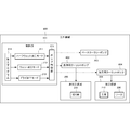
- FIG. 2 is a block diagram for explaining the functional configuration of the machine tool 200 according to the present embodiment.
- the machine tool 200 is a device that processes the work 220 using the tool 210.
- the machine tool 200 includes a coolant pump 202 that supplies coolant and a control unit 201 that controls the supply of coolant in order to cool the tool 210 and the work 220 and remove chips 230. Further, the machine tool 200 is further provided with a base coolant pump 209 for supplying the base coolant toward the floor. Although two types of coolant pumps are shown in this figure, each coolant pump may be provided according to the purpose of use of the coolant (main shaft coolant, through spindle coolant, shower coolant, base coolant, etc.).
- the control unit 201 switches modes between the half-wet processing mode 211, the wet processing mode 212, and the dry processing mode 213, and the valve control unit 215 controls each valve.
- the half-wet machining mode 211 is a mode in which coolant is supplied to the non-machining region 205 for removing chips 230 in the machine tool 200 during machining, but the coolant is not supplied to the machining region 206.
- the non-processed area refers to, for example, an area on the APC (Automatic Pallet Changer) side.
- the wet processing mode 212 is a mode in which coolant is supplied to the processing region 206 during processing.
- the dry processing mode 213 is a mode in which coolant is not supplied to the machine tool 200 during processing.
- the wet machining mode 212 supplies coolant to the machining area during machining to suppress the temperature rise of the tool 210 and the work 220.
- the dry machining mode 213 is a user who wants to reduce the amount of coolant used while extending the life of the tool 210 by stopping the supply of coolant into the machine tool 200 during machining and slowing the temperature change of the tool 210. Is the mode used by.
- the half-wet machining mode 211 does not supply coolant to the machining area 206 to extend the life of the tool 210 during machining, while supplying coolant to remove chips 230 in the machine tool 200. This is the mode used by the user.
- a cleaning coolant valve 203 and a processing coolant valve 204 are provided in each supply path.
- the valve control unit 215 opens both the cleaning coolant valve 203 and the processing coolant valve 204 in the wet processing mode 212, and opens both the cleaning coolant valve 203 and the processing coolant valve 204 in the dry processing mode 213. close. Then, in the half-wet processing mode 211, the cleaning coolant valve 203 is opened while the processing coolant valve 204 is closed.
- the control unit 201 is an NC device (Numerical Control Machine) and executes a machining program 214 which is an NC program written by a user.
- the mode is switched between the half-wet processing mode 211, the wet processing mode 212, and the dry processing mode 213.
- M codes Machine codes
- those M codes for example, M90: Wet Mode, M91: Dry Mode, M92: Half Wet Mode
- the control unit 201 controls based on the code of the machining program prepared in advance for at least one of the half wet machining mode 211, the wet machining mode 212, and the dry machining mode 213.
- An example of the machining program 214 is shown in FIG.
- the “ceiling shower” means that coolant is supplied from the ceiling to the processed region or the non-processed region by a plurality of nozzles like a shower.
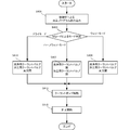
- FIG. 4 is a flowchart showing a control method by the control unit 201.
- the machining program 214 is read by the control unit 201 (NC device).
- step S405 the M code in the machining program 214 is read, and it is determined which of the half wet machining mode 211, the wet machining mode 212, and the dry machining mode 213 is selected as the mode for supplying the coolant.
- the process proceeds to step S409, and both the cleaning coolant valve 203 and the processing coolant valve 204 are opened.
- the dry processing mode 213 the process proceeds to step S411, and both the cleaning coolant valve 203 and the processing coolant valve 204 are closed.
- the half-wet processing mode 211 the process proceeds to step S407, the cleaning coolant valve 203 is opened, and the processing coolant valve 204 is closed.
- step S413 the coolant pump 202 is started, and in step S415, the tool 210 and the work 220 are driven according to the machining program to start machining.
- the chips 230 in the non-processed region can be removed without supplying coolant in the processed region.
- the processing itself is dry processing
- the chips can be removed at an appropriate timing by supplying the coolant to a place where the work is not exposed and the chips can be removed.
- supply to the machining point + supply to the wall or other structure, supply only to the machining point, or supply to only the wall or other structure is selected by the M code on the program, and the selection result is selected. Based on this, the flow path can be switched, and the coolant supply destination can be switched according to the processing.
- the control unit is only between the two modes of half-wet processing mode and wet processing mode. You may switch with. Further, the control unit may switch only between the two modes of the half-wet processing mode and the dry processing mode.
- the machine tool 200 includes a camera (not shown), and in the half-wet processing mode 211, the machine tool 200 may be controlled to supply coolant when the chip 230 is detected by the camera.
- FIG. 5 is a diagram for explaining the functional configuration of the machine tool 500 according to the present embodiment.
- the machine tool 500 according to the present embodiment is different from the second embodiment in that it has a coolant nozzle 503 that can change the injection direction of the coolant when the coolant from the coolant pump 202 is injected into the machine tool 500. ..
- the control unit 501 has a nozzle control unit 515 that controls the coolant nozzle 503. Since other configurations and operations are the same as those in the second embodiment, the same configurations and operations are designated by the same reference numerals and detailed description thereof will be omitted.
- the nozzle control unit 515 of the control unit 501 controls the coolant nozzle 503 to inject coolant into both the non-machined area 205 and the machined area 206 in the wet processing mode 212. Further, the nozzle control unit 515 controls the coolant pump 202 so that the coolant is not supplied to the machining region 206 or the non-machining region 205 in the dry machining mode 213. That is, in the dry processing mode 213, the coolant pump 202 is stopped. In the half-wet machining mode 211, the control unit 501 controls the direction of the coolant nozzle 503 so that the coolant is not applied to the machining region 206 while the coolant is injected into the non-machining region 205 to remove the chips 230.
- the chips 230 in the non-processed region can be removed without supplying coolant in the processed region.
- FIG. 6 is a diagram for explaining the functional configuration of the machine tool 600 according to the present embodiment.
- the machine tool 600 according to the present embodiment includes a cleaning coolant pump 603 that supplies coolant to the non-processed region and a processing coolant pump 604 that supplies coolant to the processed region. It differs in that. It is also different in that the control unit 601 has a pump control unit 615 that controls those pumps. Since other configurations and operations are the same as those in the second embodiment, the same configurations and operations are designated by the same reference numerals and detailed description thereof will be omitted.
- the pump control unit 615 turns on the base coolant pump 209 and the cleaning coolant pump 603 while turning off the machining coolant pump 604.
- the pump control unit 615 turns on the base coolant pump 209, the machining coolant pump 604, and the cleaning coolant pump 603 in the wet machining mode.
- the pump control unit 615 controls each pump so as to turn off the machining coolant pump 604 and the cleaning coolant pump 603 while turning on the base coolant pump 209. Thereby, the same effect as that of the second embodiment can be obtained.
- the present invention may be applied to a system composed of a plurality of devices, or may be applied to a single device. Further, the present invention is also applicable when an information processing program that realizes the functions of the embodiment is supplied to a system or an apparatus and executed by a built-in processor.
- the technical scope of the present invention includes a program installed on the computer, a medium containing the program, a server for downloading the program, and a processor for executing the program. ..
- at least a non-transitory computer readable medium containing a program for causing a computer to execute steps S401 to S413 included in the above-described embodiment is included in the technical scope of the present invention.
Landscapes
- Engineering & Computer Science (AREA)
- Mechanical Engineering (AREA)
- Human Computer Interaction (AREA)
- Manufacturing & Machinery (AREA)
- Physics & Mathematics (AREA)
- General Physics & Mathematics (AREA)
- Automation & Control Theory (AREA)
- Auxiliary Devices For Machine Tools (AREA)
Abstract
Description
加工中、ベースクーラントに加えて、工作機械内の切屑除去のために非加工領域にクーラントを供給しつつ、加工領域にはクーラントを供給しないハーフウェット加工モードと、
前記加工領域にクーラントを供給するウェット加工モード、および工作機械内にベースクーラント以外の供給を行わないドライ加工モードの少なくともいずれか1つのモードと、
の間でモード切替を行う制御部を備えた工作機械。
工具でワークに加工を行う工作機械用の制御装置であって、
加工中、工作機械内の切屑除去のために非加工領域にクーラントを供給しつつ、加工領域にクーラントを供給しないハーフウェット加工モードと、
前記加工領域にクーラントを供給するウェット加工モード、および工作機械内にクーラントの供給を行わないドライ加工モードの少なくともいずれか1つのモードと、
の間でモード切替を行う制御装置。
工具でワークに加工を行う工作機械の制御方法であって、
加工中、工作機械内の切屑除去のために非加工領域にクーラントを供給しつつ、加工領域にクーラントを供給しないハーフウェット加工モードと、
前記加工領域にクーラントを供給するウェット加工モード、および工作機械内にクーラントの供給を行わないドライ加工モードの少なくともいずれか1つのモードと、
の間でモード選択を行う制御ステップを含む工作機械の制御方法。
本発明の第1実施形態としての工作機械100について、図1を用いて説明する。図1に示すように、工作機械100は、工具110でワーク120に加工を行うものであり、クーラント供給を制御する制御部101を含む。
次に本発明の第2実施形態に係る工作機械200について、図2を用いて説明する。図2は、本実施形態に係る工作機械200の機能構成を説明するためのブロック図である。
次に本発明の第3実施形態に係る工作機械500について、図5を用いて説明する。図5は、本実施形態に係る工作機械500の機能構成を説明するための図である。本実施形態に係る工作機械500は、上記第2実施形態と比べると、クーラントポンプ202からのクーラントを工作機械500内に噴射する際にクーラントの噴射方向を変えられるクーラントノズル503を有する点で異なる。また、制御部501がそのクーラントノズル503を制御するノズル制御部515を有する点でも異なる。その他の構成および動作は、第2実施形態と同様であるため、同じ構成および動作については同じ符号を付してその詳しい説明を省略する。
次に本発明の第4実施形態に係る工作機械600について、図6を用いて説明する。図6は、本実施形態に係る工作機械600の機能構成を説明するための図である。本実施形態に係る工作機械600は、上記第2実施形態と比べると、非加工領域にクーラントを供給する洗浄用クーラントポンプ603と、加工領域にクーラントを供給する加工用クーラントポンプ604と、を備える点で異なる。また、制御部601がそれらのポンプを制御するポンプ制御部615を有する点でも異なる。その他の構成および動作は、第2実施形態と同様であるため、同じ構成および動作については同じ符号を付してその詳しい説明を省略する。
これにより、第2実施形態と同様の効果を得ることができる。
以上、実施形態を参照して本願発明を説明したが、本願発明は上記実施形態に限定されるものではない。本願発明の構成や詳細には、本願発明の技術的範囲で当業者が理解し得る様々な変更をすることができる。また、それぞれの実施形態に含まれる別々の特徴を如何様に組み合わせたシステムまたは装置も、本発明の技術的範囲に含まれる。
Claims (7)
- 工具でワークに加工を行う工作機械であって、
加工中、ベースクーラントに加えて、工作機械内の切屑除去のために非加工領域にクーラントを供給しつつ、加工領域にはクーラントを供給しないハーフウェット加工モードと、
前記加工領域にクーラントを供給するウェット加工モード、および工作機械内にベースクーラント以外の供給を行わないドライ加工モードの少なくともいずれか1つのモードと、
の間でモード切替を行う制御部を備えた工作機械。 - クーラントポンプと、
前記クーラントポンプから前記加工領域にクーラントを供給する第1供給路と、
前記クーラントポンプから前記非加工領域にクーラントを供給する第2供給路と、
をさらに備え、
前記制御部は、前記ハーフウェット加工モードでは、前記第1供給路のバルブを閉じつつ前記第2供給路のバルブを開き、前記ウェット加工モードでは、前記第1、第2供給路のバルブを開き、前記ドライ加工モードでは、前記第1、第2供給路のバルブを閉じるように、各バルブを制御する請求項1に記載の工作機械。 - クーラントポンプと、
前記クーラントポンプからのクーラントを工作機械内に噴射するノズルと、
をさらに備え、
前記制御部は、前記ハーフウェット加工モードでは、前記加工領域にはクーラントが供給されず、前記非加工領域にクーラントが供給されるように前記ノズルの方向を制御し、前記ウェット加工モードでは、前記加工領域および前記非加工領域にクーラントが供給されるように前記ノズルの方向を制御する請求項1または2に記載の工作機械。 - ベースクーラントポンプと、
前記加工領域にクーラントを供給する加工用クーラントポンプと、
前記非加工領域にクーラントを供給する洗浄用クーラントポンプと、
をさらに備え、
前記制御部は、前記ハーフウェット加工モードでは、前記加工用クーラントポンプをオフにしつつ、前記ベースクーラントポンプおよび前記洗浄用クーラントポンプをオンにし、前記ウェット加工モードでは、前記ベースクーラントポンプ、前記加工用クーラントポンプおよび前記洗浄用クーラントポンプをオンにし、前記ドライ加工モードでは、前記ベースクーラントポンプをオンにしつつ、前記加工用クーラントポンプおよび前記洗浄用クーラントポンプをオフにするように、各ポンプを制御する請求項1に記載の工作機械。 - 前記制御部は、
前記ハーフウェット加工モード、前記ウェット加工モード、および前記ドライ加工モードの少なくともいずれか一つのモード用にあらかじめ用意された加工プログラムのコードに基づいて、制御を行う請求項1乃至4のいずれか1項に記載の工作機械。 - 工具でワークに加工を行う工作機械用の制御装置であって、
加工中、工作機械内の切屑除去のために非加工領域にクーラントを供給しつつ、加工領域にクーラントを供給しないハーフウェット加工モードと、
前記加工領域にクーラントを供給するウェット加工モード、および工作機械内にクーラントの供給を行わないドライ加工モードの少なくともいずれか1つのモードと、
の間でモード切替を行う制御装置。 - 工具でワークに加工を行う工作機械の制御方法であって、
加工中、工作機械内の切屑除去のために非加工領域にクーラントを供給しつつ、加工領域にクーラントを供給しないハーフウェット加工モードと、
前記加工領域にクーラントを供給するウェット加工モード、および工作機械内にクーラントの供給を行わないドライ加工モードの少なくともいずれか1つのモードと、
の間でモード選択を行う制御ステップを含む工作機械の制御方法。
Priority Applications (3)
| Application Number | Priority Date | Filing Date | Title |
|---|---|---|---|
| US17/759,493 US12459070B2 (en) | 2020-01-28 | 2021-01-05 | Machine tool, and control apparatus and control method thereof |
| EP21748347.8A EP4098397B1 (en) | 2020-01-28 | 2021-01-05 | Machine tool, and control device and control method for same |
| CN202180011433.5A CN115023315A (zh) | 2020-01-28 | 2021-01-05 | 机床及其控制装置和控制方法 |
Applications Claiming Priority (2)
| Application Number | Priority Date | Filing Date | Title |
|---|---|---|---|
| JP2020011804A JP6777829B1 (ja) | 2020-01-28 | 2020-01-28 | 工作機械およびその制御装置ならびに制御方法 |
| JP2020-011804 | 2020-01-28 |
Publications (1)
| Publication Number | Publication Date |
|---|---|
| WO2021153166A1 true WO2021153166A1 (ja) | 2021-08-05 |
Family
ID=72916129
Family Applications (1)
| Application Number | Title | Priority Date | Filing Date |
|---|---|---|---|
| PCT/JP2021/000084 Ceased WO2021153166A1 (ja) | 2020-01-28 | 2021-01-05 | 工作機械およびその制御装置ならびに制御方法 |
Country Status (5)
| Country | Link |
|---|---|
| US (1) | US12459070B2 (ja) |
| EP (1) | EP4098397B1 (ja) |
| JP (1) | JP6777829B1 (ja) |
| CN (1) | CN115023315A (ja) |
| WO (1) | WO2021153166A1 (ja) |
Families Citing this family (1)
| Publication number | Priority date | Publication date | Assignee | Title |
|---|---|---|---|---|
| JP7249472B1 (ja) * | 2022-07-27 | 2023-03-30 | ヤマザキマザック株式会社 | クーラント供給装置、工作機械、工作機械へのクーラント供給方法、及び、プログラム |
Citations (7)
| Publication number | Priority date | Publication date | Assignee | Title |
|---|---|---|---|---|
| JPH10180585A (ja) * | 1996-11-06 | 1998-07-07 | Makino Milling Mach Co Ltd | 自動切屑除去装置を備えた工作機械 |
| JPH11504866A (ja) * | 1995-05-02 | 1999-05-11 | ザ グリーソン ワークス | 工作機械の切屑除去装置 |
| JP2002103133A (ja) * | 2000-09-27 | 2002-04-09 | Nachi Fujikoshi Corp | ブローチ盤 |
| JP2002524278A (ja) * | 1998-09-09 | 2002-08-06 | ザ グリーソン ワークス | 歯付き加工物を製造するための工作機械の機械加工室からチップを除去する装置 |
| JP2003089036A (ja) * | 2001-09-18 | 2003-03-25 | Citizen Watch Co Ltd | セミドライ加工用ミスト発生システム、ミスト混合装置、ミスト分配装置及び数値制御工作機械 |
| JP2007152489A (ja) | 2005-12-05 | 2007-06-21 | Fanuc Ltd | 工作機械のクーラント供給装置 |
| JP2020011804A (ja) | 2018-07-17 | 2020-01-23 | 日本製鉄株式会社 | 逸走防止装置 |
Family Cites Families (15)
| Publication number | Priority date | Publication date | Assignee | Title |
|---|---|---|---|---|
| JPS5844111U (ja) * | 1981-09-21 | 1983-03-24 | 豊田工機株式会社 | 中ぐり加工装置 |
| JPH0847839A (ja) * | 1994-08-02 | 1996-02-20 | Makino Milling Mach Co Ltd | 各種切屑処理の可能な工作機械 |
| JP3549741B2 (ja) | 1998-09-08 | 2004-08-04 | 日本スピードショア株式会社 | 霧状体供給装置 |
| JP2002066871A (ja) * | 2000-09-04 | 2002-03-05 | Enshu Ltd | 加工方法と極微小ミスト生成装置、ワークの冷却方法、主軸の冷却方法 |
| JP2002129176A (ja) * | 2000-10-27 | 2002-05-09 | Makino Milling Mach Co Ltd | 加工液及びその加工液を用いた加工方法 |
| JP2003019637A (ja) * | 2001-07-09 | 2003-01-21 | Fuji Heavy Ind Ltd | 工作機械用クーラントの清浄装置 |
| JP2005335015A (ja) * | 2004-05-27 | 2005-12-08 | Toyota Motor Corp | プリセットスクリュー、工具ホルダおよび流体供給方法 |
| JP2008213099A (ja) * | 2007-03-06 | 2008-09-18 | Nsk Ltd | ブローチ盤 |
| EP2756920B1 (en) * | 2011-09-16 | 2019-03-27 | Makino Milling Machine Co. Ltd. | Coolant supply device |
| JP6625795B2 (ja) * | 2014-09-30 | 2019-12-25 | ファナック株式会社 | 切削液噴射装置 |
| JP6653677B2 (ja) | 2017-03-24 | 2020-02-26 | Dmg森精機株式会社 | チップコンベアおよび工作機械 |
| JP7061890B2 (ja) * | 2018-02-20 | 2022-05-02 | シチズン時計株式会社 | 工作機械 |
| JP2020006462A (ja) * | 2018-07-06 | 2020-01-16 | Dgshape株式会社 | 湿式の加工装置における洗浄用治具および洗浄機構 |
| US11273531B2 (en) * | 2018-09-10 | 2022-03-15 | Fanuc America Corporation | Smart coolant pump |
| CN109514337B (zh) | 2018-11-12 | 2021-07-23 | 西安精雕软件科技有限公司 | 一种能够快速实现干湿加工切换的除屑系统及其使用方法 |
-
2020
- 2020-01-28 JP JP2020011804A patent/JP6777829B1/ja active Active
-
2021
- 2021-01-05 EP EP21748347.8A patent/EP4098397B1/en active Active
- 2021-01-05 CN CN202180011433.5A patent/CN115023315A/zh active Pending
- 2021-01-05 WO PCT/JP2021/000084 patent/WO2021153166A1/ja not_active Ceased
- 2021-01-05 US US17/759,493 patent/US12459070B2/en active Active
Patent Citations (7)
| Publication number | Priority date | Publication date | Assignee | Title |
|---|---|---|---|---|
| JPH11504866A (ja) * | 1995-05-02 | 1999-05-11 | ザ グリーソン ワークス | 工作機械の切屑除去装置 |
| JPH10180585A (ja) * | 1996-11-06 | 1998-07-07 | Makino Milling Mach Co Ltd | 自動切屑除去装置を備えた工作機械 |
| JP2002524278A (ja) * | 1998-09-09 | 2002-08-06 | ザ グリーソン ワークス | 歯付き加工物を製造するための工作機械の機械加工室からチップを除去する装置 |
| JP2002103133A (ja) * | 2000-09-27 | 2002-04-09 | Nachi Fujikoshi Corp | ブローチ盤 |
| JP2003089036A (ja) * | 2001-09-18 | 2003-03-25 | Citizen Watch Co Ltd | セミドライ加工用ミスト発生システム、ミスト混合装置、ミスト分配装置及び数値制御工作機械 |
| JP2007152489A (ja) | 2005-12-05 | 2007-06-21 | Fanuc Ltd | 工作機械のクーラント供給装置 |
| JP2020011804A (ja) | 2018-07-17 | 2020-01-23 | 日本製鉄株式会社 | 逸走防止装置 |
Non-Patent Citations (1)
| Title |
|---|
| See also references of EP4098397A4 |
Also Published As
| Publication number | Publication date |
|---|---|
| US20240217044A1 (en) | 2024-07-04 |
| US12459070B2 (en) | 2025-11-04 |
| CN115023315A (zh) | 2022-09-06 |
| JP6777829B1 (ja) | 2020-10-28 |
| EP4098397A1 (en) | 2022-12-07 |
| EP4098397B1 (en) | 2026-04-15 |
| EP4098397A4 (en) | 2023-07-19 |
| JP2021115682A (ja) | 2021-08-10 |
Similar Documents
| Publication | Publication Date | Title |
|---|---|---|
| JP5576625B2 (ja) | 機械のエネルギー消費を削減するための装置及び方法 | |
| JP5415311B2 (ja) | 自動運転を再開可能な工作機械の制御方法およびその装置 | |
| JP6777829B1 (ja) | 工作機械およびその制御装置ならびに制御方法 | |
| JPH01146642A (ja) | 切削工具の停止制御装置 | |
| JP2015079384A (ja) | 休止点が指定可能な数値制御装置 | |
| US6719677B2 (en) | Automatic tool changer | |
| JP2004216504A (ja) | ローダ制御装置 | |
| JP2004086306A (ja) | 多系統数値制御装置 | |
| JP2002273601A (ja) | 多軸工作機械 | |
| JP6181709B2 (ja) | 工作機械の制御装置 | |
| JP2015099553A (ja) | テーブル形式データで複数の指令を同時に実行する機能を備えた数値制御装置 | |
| US11782415B2 (en) | Numerical controller having scalable performance | |
| KR20140080845A (ko) | 수치제어 공작기계의 전원 세이빙 제어 방법 | |
| JP4859467B2 (ja) | 2主軸対向旋盤の再起動方法 | |
| JP2000317769A (ja) | 切削液の供給を制御する機能を有する数値制御装置 | |
| JP7817362B2 (ja) | データ収集装置およびコンピュータ読み取り可能な記憶媒体 | |
| WO2023002526A1 (ja) | 工作機械 | |
| JP2001282322A (ja) | シーケンス・コントローラ | |
| WO2026047827A1 (ja) | 工作機械制御装置及び工作機械 | |
| JP4208600B2 (ja) | Nc工作機械 | |
| JP2007213241A (ja) | 割り込み加工可能な数値制御工作機械 | |
| JP2014235466A (ja) | 工作機械 | |
| KR100600016B1 (ko) | 스핀들 유니트의 워밍업 제어방법 | |
| KR101931555B1 (ko) | 공작기계의 제어 시스템 | |
| KR200424406Y1 (ko) | 공작기계용 트윈 암 구동 모터의 제어 장치 |
Legal Events
| Date | Code | Title | Description |
|---|---|---|---|
| 121 | Ep: the epo has been informed by wipo that ep was designated in this application |
Ref document number: 21748347 Country of ref document: EP Kind code of ref document: A1 |
|
| NENP | Non-entry into the national phase |
Ref country code: DE |
|
| ENP | Entry into the national phase |
Ref document number: 2021748347 Country of ref document: EP Effective date: 20220829 |
|
| WWG | Wipo information: grant in national office |
Ref document number: 17759493 Country of ref document: US |
|
| WWG | Wipo information: grant in national office |
Ref document number: 2021748347 Country of ref document: EP |