WO2021153275A1 - 点火システム - Google Patents
点火システム Download PDFInfo
- Publication number
- WO2021153275A1 WO2021153275A1 PCT/JP2021/001282 JP2021001282W WO2021153275A1 WO 2021153275 A1 WO2021153275 A1 WO 2021153275A1 JP 2021001282 W JP2021001282 W JP 2021001282W WO 2021153275 A1 WO2021153275 A1 WO 2021153275A1
- Authority
- WO
- WIPO (PCT)
- Prior art keywords
- top dead
- dead center
- ignition
- spark
- communication hole
- Prior art date
- Legal status (The legal status is an assumption and is not a legal conclusion. Google has not performed a legal analysis and makes no representation as to the accuracy of the status listed.)
- Ceased
Links
Images




Classifications
-
- F—MECHANICAL ENGINEERING; LIGHTING; HEATING; WEAPONS; BLASTING
- F02—COMBUSTION ENGINES; HOT-GAS OR COMBUSTION-PRODUCT ENGINE PLANTS
- F02P—IGNITION, OTHER THAN COMPRESSION IGNITION, FOR INTERNAL-COMBUSTION ENGINES; TESTING OF IGNITION TIMING IN COMPRESSION-IGNITION ENGINES
- F02P5/00—Advancing or retarding ignition; Control therefor
- F02P5/04—Advancing or retarding ignition; Control therefor automatically, as a function of the working conditions of the engine or vehicle or of the atmospheric conditions
- F02P5/145—Advancing or retarding ignition; Control therefor automatically, as a function of the working conditions of the engine or vehicle or of the atmospheric conditions using electrical means
- F02P5/15—Digital data processing
-
- F—MECHANICAL ENGINEERING; LIGHTING; HEATING; WEAPONS; BLASTING
- F02—COMBUSTION ENGINES; HOT-GAS OR COMBUSTION-PRODUCT ENGINE PLANTS
- F02B—INTERNAL-COMBUSTION PISTON ENGINES; COMBUSTION ENGINES IN GENERAL
- F02B19/00—Engines characterised by precombustion chambers
- F02B19/12—Engines characterised by precombustion chambers with positive ignition
-
- F—MECHANICAL ENGINEERING; LIGHTING; HEATING; WEAPONS; BLASTING
- F02—COMBUSTION ENGINES; HOT-GAS OR COMBUSTION-PRODUCT ENGINE PLANTS
- F02P—IGNITION, OTHER THAN COMPRESSION IGNITION, FOR INTERNAL-COMBUSTION ENGINES; TESTING OF IGNITION TIMING IN COMPRESSION-IGNITION ENGINES
- F02P13/00—Sparking plugs structurally combined with other parts of internal-combustion engines
-
- F—MECHANICAL ENGINEERING; LIGHTING; HEATING; WEAPONS; BLASTING
- F02—COMBUSTION ENGINES; HOT-GAS OR COMBUSTION-PRODUCT ENGINE PLANTS
- F02P—IGNITION, OTHER THAN COMPRESSION IGNITION, FOR INTERNAL-COMBUSTION ENGINES; TESTING OF IGNITION TIMING IN COMPRESSION-IGNITION ENGINES
- F02P15/00—Electric spark ignition having characteristics not provided for in, or of interest apart from, groups F02P1/00 - F02P13/00 and combined with layout of ignition circuits
-
- F—MECHANICAL ENGINEERING; LIGHTING; HEATING; WEAPONS; BLASTING
- F02—COMBUSTION ENGINES; HOT-GAS OR COMBUSTION-PRODUCT ENGINE PLANTS
- F02P—IGNITION, OTHER THAN COMPRESSION IGNITION, FOR INTERNAL-COMBUSTION ENGINES; TESTING OF IGNITION TIMING IN COMPRESSION-IGNITION ENGINES
- F02P9/00—Electric spark ignition control, not otherwise provided for
- F02P9/002—Control of spark intensity, intensifying, lengthening, suppression
-
- H—ELECTRICITY
- H01—ELECTRIC ELEMENTS
- H01T—SPARK GAPS; OVERVOLTAGE ARRESTERS USING SPARK GAPS; SPARKING PLUGS; CORONA DEVICES; GENERATING IONS TO BE INTRODUCED INTO NON-ENCLOSED GASES
- H01T13/00—Sparking plugs
- H01T13/54—Sparking plugs having electrodes arranged in a partly-enclosed ignition chamber
-
- F—MECHANICAL ENGINEERING; LIGHTING; HEATING; WEAPONS; BLASTING
- F02—COMBUSTION ENGINES; HOT-GAS OR COMBUSTION-PRODUCT ENGINE PLANTS
- F02P—IGNITION, OTHER THAN COMPRESSION IGNITION, FOR INTERNAL-COMBUSTION ENGINES; TESTING OF IGNITION TIMING IN COMPRESSION-IGNITION ENGINES
- F02P5/00—Advancing or retarding ignition; Control therefor
- F02P5/04—Advancing or retarding ignition; Control therefor automatically, as a function of the working conditions of the engine or vehicle or of the atmospheric conditions
- F02P5/145—Advancing or retarding ignition; Control therefor automatically, as a function of the working conditions of the engine or vehicle or of the atmospheric conditions using electrical means
- F02P5/15—Digital data processing
- F02P5/1502—Digital data processing using one central computing unit
- F02P5/1504—Digital data processing using one central computing unit with particular means during a transient phase, e.g. acceleration, deceleration, gear change
-
- F—MECHANICAL ENGINEERING; LIGHTING; HEATING; WEAPONS; BLASTING
- F02—COMBUSTION ENGINES; HOT-GAS OR COMBUSTION-PRODUCT ENGINE PLANTS
- F02P—IGNITION, OTHER THAN COMPRESSION IGNITION, FOR INTERNAL-COMBUSTION ENGINES; TESTING OF IGNITION TIMING IN COMPRESSION-IGNITION ENGINES
- F02P5/00—Advancing or retarding ignition; Control therefor
- F02P5/04—Advancing or retarding ignition; Control therefor automatically, as a function of the working conditions of the engine or vehicle or of the atmospheric conditions
- F02P5/145—Advancing or retarding ignition; Control therefor automatically, as a function of the working conditions of the engine or vehicle or of the atmospheric conditions using electrical means
- F02P5/15—Digital data processing
- F02P5/1502—Digital data processing using one central computing unit
- F02P5/1508—Digital data processing using one central computing unit with particular means during idling
-
- H—ELECTRICITY
- H01—ELECTRIC ELEMENTS
- H01T—SPARK GAPS; OVERVOLTAGE ARRESTERS USING SPARK GAPS; SPARKING PLUGS; CORONA DEVICES; GENERATING IONS TO BE INTRODUCED INTO NON-ENCLOSED GASES
- H01T13/00—Sparking plugs
- H01T13/20—Sparking plugs characterised by features of the electrodes or insulation
-
- H—ELECTRICITY
- H01—ELECTRIC ELEMENTS
- H01T—SPARK GAPS; OVERVOLTAGE ARRESTERS USING SPARK GAPS; SPARKING PLUGS; CORONA DEVICES; GENERATING IONS TO BE INTRODUCED INTO NON-ENCLOSED GASES
- H01T13/00—Sparking plugs
- H01T13/20—Sparking plugs characterised by features of the electrodes or insulation
- H01T13/32—Sparking plugs characterised by features of the electrodes or insulation characterised by features of the earthed electrode
-
- Y—GENERAL TAGGING OF NEW TECHNOLOGICAL DEVELOPMENTS; GENERAL TAGGING OF CROSS-SECTIONAL TECHNOLOGIES SPANNING OVER SEVERAL SECTIONS OF THE IPC; TECHNICAL SUBJECTS COVERED BY FORMER USPC CROSS-REFERENCE ART COLLECTIONS [XRACs] AND DIGESTS
- Y02—TECHNOLOGIES OR APPLICATIONS FOR MITIGATION OR ADAPTATION AGAINST CLIMATE CHANGE
- Y02T—CLIMATE CHANGE MITIGATION TECHNOLOGIES RELATED TO TRANSPORTATION
- Y02T10/00—Road transport of goods or passengers
- Y02T10/10—Internal combustion engine [ICE] based vehicles
- Y02T10/12—Improving ICE efficiencies
Definitions
- the ignition system generally has a spark plug.
- the spark plug often has a center electrode and a ground electrode facing it.
- the ground electrode has an upright portion extending in the length direction of the spark plug and an opposing portion extending inward from the tip of the upright portion and facing the center electrode. Then, a voltage is applied to the discharge gap between the center electrode and the facing portion to generate a discharge spark, thereby igniting the fuel in the combustion chamber.
- the head 20 is provided with an intake passage 21 for sucking gas into the combustion chamber 30 and an exhaust passage 29 for discharging the gas in the combustion chamber 30.
- An intake valve 24 is installed in the intake passage 21, and an exhaust valve 26 is installed in the exhaust passage 29.
- the intake valve 24 is driven by the intake cam 23, and the exhaust valve 26 is driven by the exhaust cam 27.
- the head 20 is provided with a fuel injection device 22 for injecting fuel into the intake passage 21.
- the ignition system 70 has an ignition plug 40 attached to the head 20, an ignition control unit 50 that controls the spark plug 40, and an airflow support structure As that facilitates the flow of airflow into the discharge gap 45 of the ignition plug 40. ..
- the ignition control unit 50 is an ECU (electronic control unit) or the like, and changes the ignition timing according to the operating conditions of the engine 90 such as the rotation speed and the load of the engine 90. Further, the ignition control unit 50 performs post-top dead center ignition control that ignites Ta (that is, expansion stroke) after the compression top dead center when the engine 90 is in a predetermined operating condition such as during first idling. On the other hand, in other operating conditions, pre-dead center ignition control is performed to ignite the compression top dead center Tb (that is, the compression stroke).
- the above-mentionedling is a period in which the idle speed is made higher than usual due to catalyst warm-up or the like after the engine 90 is started.
- the piston 18 rises in Tb (compression stroke) before the compression top dead center.
- Tb compression stroke
- a continuous airflow A2 flowing from the main chamber 31 side to the sub chamber 38 side is generated in the combustion chamber 30.
- FIG. 4 is a graph showing an image of changes in the flow velocities (absolute values) of the general airflow A1 and the continuous airflow A2 shown above.
- the flow velocity of the general airflow A1 decreases as it approaches the compression top dead center Td in Tb before the compression top dead center. Then, the general airflow A1 collapses or extremely decreases at or near the compression top dead center Td. Then, the general airflow A1 is generated again in Ta after the compression top dead center after a while from the compression top dead center Td. This is because the general airflow A1 due to the tumble or swirl does not occur even if the piston 18 starts to descend and the air pressure in the main chamber 31 starts to decrease, until a predetermined trigger is given.
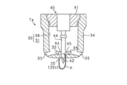
- FIG. 8 is a cross-sectional view showing the sub chamber 38 of the present embodiment and its surroundings.
- the partition wall 34 is provided with a plurality of communication holes 35, but the central communication hole 35c is not provided.
- the discharge gap 45 is provided in the sub chamber 38 at a position farther from the communication hole 35 than in the case of the first embodiment.
- the partition wall 34 is formed with protrusions 36 constituting one electrode protruding toward the center electrode 44, which is the other electrode.
- a discharge gap 45 is formed between the protrusion 36 and the center electrode 44. Then, at the time of ignition control after top dead center, the discharge spark F extends toward the predetermined communication hole 35 by the air flow flowing from the sub chamber 38 into the main chamber 31 through the predetermined communication hole 35.
- the partition wall 34 also serves as the ground electrode of the spark plug 40, but the spark plug 40 may have a ground electrode separately from the partition wall 34.
- a partition wall 34 is provided on the outside of the ground electrode, and the discharge gap 45 between the ground electrode and the center electrode 44 may be close to the communication hole 35 as the airflow support structure As.
- the engine 90 is a 4-stroke engine, but the engine 90 has one combustion cycle consisting of only a compression stroke and an expansion stroke, and intake and exhaust are performed in the latter half of the expansion stroke and the first half of the compression stroke.
- a two-stroke engine that does both may be used.
Landscapes
- Engineering & Computer Science (AREA)
- Chemical & Material Sciences (AREA)
- Combustion & Propulsion (AREA)
- Mechanical Engineering (AREA)
- General Engineering & Computer Science (AREA)
- Signal Processing (AREA)
- Spark Plugs (AREA)
- Combustion Methods Of Internal-Combustion Engines (AREA)
Abstract
Description
図1は、第1実施形態の点火システム70及びその周辺を示す断面図である。この点火システム70は、エンジン90に対して設置されている。エンジン90は、一燃焼サイクルが吸気行程→圧縮行程→膨張行程→排気行程の4行程からなる4ストロークエンジンである。以下では、それらのうちの圧縮行程と膨張行程との間の上死点を「圧縮上死点Td」という。エンジン90は、シリンダ10と、その上部に取り付けられているヘッド20とを有する。
次に第2実施形態について説明する。以下の実施形態では、それ以前の実施形態のものと同一の又は対応する部材等は同一の符号を付する。本実施形態については、第1実施形態をベースにこれと異なる点を中心に説明する。
以上の実施形態は、次のように変更して実施できる。例えば、第1実施形態では、気流支援構造Asとして、放電ギャップ45が中央連通孔35cに近接している構造を採用しているが、これに代えて又は加えて、上死点後火花期間において放電ギャップ45に空気又は混合気を吹き付ける吹付装置を、気流支援構造Asとして設けてもよい。また、この場合において、隔壁34をなくして、主室31と副室38とを一続きの燃焼室30にしてもよい。
Claims (15)
- エンジン(90)の燃焼室(30)内において放電ギャップ(45)に電圧を印加して放電火花(F)を発生させることにより燃料に点火する点火プラグ(40)と、前記点火プラグを制御する点火制御部(50)とを有し、
前記点火制御部は、前記エンジンが所定の運転状況の時には、圧縮上死点後(Ta)に前記点火を行う上死点後点火制御を行う、点火システムにおいて、
気流を少なくとも前記圧縮上死点後に前記放電ギャップに流れ易くする気流支援構造(As)を有し、
前記気流支援構造と前記点火のタイミング(Taf)とにより、前記上死点後点火制御における前記放電火花の発生期間である上死点後火花期間に前記放電ギャップに流速5m/s以上の気流が流れるように構成されている、点火システム。 - 前記燃焼室は、連通孔(35)が設けられている隔壁(34)により主室(31)と副室(38)とに区分けされることにより、前記圧縮上死点後には、前記副室内から気流が前記連通孔を通じて前記主室内に流れ込むように構成されており、
前記気流支援構造として、前記上死点後火花期間に前記放電ギャップに前記流速5m/s以上の気流が流れる状態まで、前記放電ギャップが前記連通孔に近接している、請求項1に記載の点火システム。 - 前記放電ギャップは、前記副室内又は前記連通孔内に配置されており、前記上死点後点火制御の際には、前記放電火花が気流により前記連通孔を通じて前記主室内にまで伸長する、請求項2に記載の点火システム。
- 前記隔壁に前記連通孔が複数設けられており、
前記気流支援構造として、前記上死点後火花期間に前記放電ギャップに前記流速5m/s以上の気流が流れる状態まで、前記放電ギャップが複数の前記連通孔のうちの1つの所定連通孔(35c)に近接している、請求項2又は3に記載の点火システム。 - エンジン(90)の燃焼室(30)内において放電ギャップ(45)に電圧を印加して放電火花(F)を発生させることにより燃料に点火する点火プラグ(40)と、前記点火プラグを制御する点火制御部(50)とを有し、
前記点火制御部は、前記エンジンが所定の運転状況の時には、圧縮上死点後(Ta)に前記点火を行う上死点後点火制御を行う、点火システムにおいて、
前記燃焼室は、複数の連通孔(35)が設けられている隔壁(34)により主室(31)と副室(38)とに区分けされることにより、前記圧縮上死点後には、前記副室内から気流が前記連通孔を通じて前記主室内に流れ込むように構成されており、
前記放電ギャップは、複数の前記連通孔のうち、所定の前記連通孔である所定連通孔(35c)に最も近接した状態で前記副室内又は前記所定連通孔内に配置されており、
前記上死点後点火制御の際には、前記放電火花が気流により前記所定連通孔を通じて前記主室内にまで伸長する、点火システム。 - 前記点火制御部は、前記所定の運転状況の時以外の時に、圧縮上死点前(Tb)に前記点火を行う上死点前点火制御を行うものであり、
少なくとも前記上死点前点火制御における点火の後には、少なくとも前記所定連通孔以外の前記連通孔から炎が前記主室内に向けて放出される、請求項4又は5に記載の点火システム。 - 前記所定連通孔に比べて、前記所定連通孔以外の前記連通孔から前記炎が強く放出される、請求項6に記載の点火システム。
- 前記放電ギャップは、前記副室内に設けられており、
前記上死点後点火制御の際には、前記副室内から所定の前記連通孔である所定連通孔を通じて前記主室内に流れ込む気流により、前記放電火花が前記所定連通孔に向けて伸長する、請求項2~7のいずれか1項に記載の点火システム。 - エンジン(90)の燃焼室(30)内において放電ギャップ(45)に電圧を印加して放電火花(F)を発生させることにより燃料に点火する点火プラグ(40)と、前記点火プラグを制御する点火制御部(50)とを有し、
前記点火制御部は、前記エンジンが所定の運転状況の時には、圧縮上死点後(Ta)に前記点火を行う上死点後点火制御を行う、点火システムにおいて、
前記燃焼室は、一又は複数の連通孔(35)が設けられている隔壁(34)により主室(31)と副室(38)とに区分けされることにより、前記圧縮上死点後には、前記副室内から気流が所定の前記連通孔である所定連通孔を通じて前記主室内に流れ込むように構成されており、
前記放電ギャップは、前記副室内に設けられており、
前記上死点後点火制御の際には、前記副室内から前記所定連通孔を通じて前記主室内に流れ込む気流により、前記放電火花が前記所定連通孔に向けて伸長する、点火システム。 - 前記点火制御部は、前記上死点後点火制御の際には、前記放電火花が発生してから当該放電火花が前記所定連通孔にまで伸長するのに最低限必要な期間としての必要期間以上、当該放電火花が維持されるように前記点火プラグを制御する、請求項8又は9に記載の点火システム。
- 前記点火制御部は、前記上死点後点火制御の際には、前記放電火花が発生してから当該放電火花が前記所定連通孔を通じて前記主室内にまで伸長するのに最低限必要な期間としての必要期間以上、当該放電火花が維持されるように前記点火プラグを制御する、請求項8又は9に記載の点火システム。
- 前記点火制御部は、前記エンジンの運転状況に基づいて前記必要期間を算出し、算出された前記必要期間以上、前記放電火花が維持されるように前記点火プラグを制御する、請求項10又は11に記載の点火システム。
- 前記燃焼室はシリンダ(10)内に形成されており、前記シリンダの中心線(X)上に前記連通孔が設けられており、
前記上死点後点火制御の際には、前記放電火花が前記中心線上の前記連通孔を通じて前記中心線の長さ方向に伸長する、請求項2~12のいずれか1項に記載の点火システム。 - 前記放電ギャップは2つの電極(34,44)間に形成されており、前記隔壁は、前記2つの電極のうちの一方の電極(34)を兼ねている、請求項2~13のいずれか1項に記載の点火システム。
- 前記放電ギャップは2つの電極(36,44)間に形成されており、前記隔壁には、一方の前記電極を構成する突起(36)が、他方の前記電極(44)に向けて突出する形で形成されている、請求項2~13のいずれか1項に記載の点火システム。
Priority Applications (3)
| Application Number | Priority Date | Filing Date | Title |
|---|---|---|---|
| CN202180011851.4A CN115038858B (zh) | 2020-01-29 | 2021-01-15 | 点火系统 |
| EP21747804.9A EP4098857A4 (en) | 2020-01-29 | 2021-01-15 | IGNITION SYSTEM |
| US17/874,671 US11754032B2 (en) | 2020-01-29 | 2022-07-27 | Ignition system |
Applications Claiming Priority (4)
| Application Number | Priority Date | Filing Date | Title |
|---|---|---|---|
| JP2020012918 | 2020-01-29 | ||
| JP2020-012918 | 2020-01-29 | ||
| JP2020-067668 | 2020-04-03 | ||
| JP2020067668A JP7347308B2 (ja) | 2020-01-29 | 2020-04-03 | 点火システム |
Related Child Applications (1)
| Application Number | Title | Priority Date | Filing Date |
|---|---|---|---|
| US17/874,671 Continuation US11754032B2 (en) | 2020-01-29 | 2022-07-27 | Ignition system |
Publications (1)
| Publication Number | Publication Date |
|---|---|
| WO2021153275A1 true WO2021153275A1 (ja) | 2021-08-05 |
Family
ID=77078875
Family Applications (1)
| Application Number | Title | Priority Date | Filing Date |
|---|---|---|---|
| PCT/JP2021/001282 Ceased WO2021153275A1 (ja) | 2020-01-29 | 2021-01-15 | 点火システム |
Country Status (4)
| Country | Link |
|---|---|
| US (1) | US11754032B2 (ja) |
| EP (1) | EP4098857A4 (ja) |
| CN (1) | CN115038858B (ja) |
| WO (1) | WO2021153275A1 (ja) |
Cited By (1)
| Publication number | Priority date | Publication date | Assignee | Title |
|---|---|---|---|---|
| EP4194672A4 (en) * | 2020-08-07 | 2024-02-07 | Denso Corporation | IGNITION SYSTEM |
Citations (5)
| Publication number | Priority date | Publication date | Assignee | Title |
|---|---|---|---|---|
| JPH0281925A (ja) * | 1988-09-19 | 1990-03-22 | Yanmar Diesel Engine Co Ltd | 副室式ガス機関 |
| JP2003083124A (ja) * | 2001-09-06 | 2003-03-19 | Mazda Motor Corp | 火花点火式直噴エンジンの制御装置 |
| JP2010261407A (ja) * | 2009-05-11 | 2010-11-18 | Nippon Soken Inc | 副燃焼室式点火装置 |
| WO2014149290A1 (en) * | 2013-03-15 | 2014-09-25 | Cummins, Inc. | Pre-chamber for internal combustion engine |
| US20160053673A1 (en) * | 2013-03-12 | 2016-02-25 | Prometheus Applied Technologies, Llc | Active scavenge prechamber |
Family Cites Families (17)
| Publication number | Priority date | Publication date | Assignee | Title |
|---|---|---|---|---|
| US1403886A (en) * | 1920-05-24 | 1922-01-17 | Young Monte | Spark plug |
| US4974559A (en) * | 1987-02-19 | 1990-12-04 | Hi-Tech International Laboratory Company, Limited | Combustion system and combustion apparatus for internal combustion engine |
| US4930473A (en) * | 1988-12-09 | 1990-06-05 | Texas Ignitors Company, Inc. | Swirl chamber and spark plug assembly |
| EP1766208B1 (en) * | 2004-06-24 | 2019-12-25 | Woodward, Inc. | Pre-chamber spark plug |
| EP1873380B1 (en) * | 2006-06-26 | 2016-10-05 | Nissan Motor Co., Ltd. | Control device and control method for spark-ignited internal-combustion engine |
| JP5122367B2 (ja) | 2008-05-09 | 2013-01-16 | 大阪瓦斯株式会社 | エンジン及びエンジン用点火プラグ |
| US8584648B2 (en) * | 2010-11-23 | 2013-11-19 | Woodward, Inc. | Controlled spark ignited flame kernel flow |
| JP2014525546A (ja) * | 2011-09-03 | 2014-09-29 | プロメテウス アプライド テクノロジーズ,エルエルシー | ガスエンジン用のプレチャンバスパークプラグにおいて高出力火炎ジェットを達成して消炎及び自己発火を抑制する方法及び装置 |
| JP5919214B2 (ja) | 2013-03-28 | 2016-05-18 | 株式会社日本自動車部品総合研究所 | 内燃機関用のスパークプラグ |
| US8839762B1 (en) * | 2013-06-10 | 2014-09-23 | Woodward, Inc. | Multi-chamber igniter |
| JP6206158B2 (ja) * | 2013-12-17 | 2017-10-04 | トヨタ自動車株式会社 | 火花点火式内燃機関の制御システム |
| CN204478138U (zh) * | 2014-12-19 | 2015-07-15 | 中国南方航空工业(集团)有限公司 | 发动机的预燃室 |
| JP6797000B2 (ja) * | 2016-11-09 | 2020-12-09 | 株式会社Soken | 内燃機関の点火制御装置 |
| CN107332109A (zh) * | 2017-04-26 | 2017-11-07 | 周向进 | 一种喷火的火花塞及其内燃机和汽车 |
| US10666023B2 (en) | 2018-07-03 | 2020-05-26 | Ngk Spark Plug Co., Ltd. | Spark plug |
| JP7413746B2 (ja) | 2019-03-21 | 2024-01-16 | 株式会社デンソー | 内燃機関用のスパークプラグ及びこれを備えた内燃機関 |
| JP7563035B2 (ja) * | 2020-08-07 | 2024-10-08 | 株式会社デンソー | 点火システム |
-
2021
- 2021-01-15 EP EP21747804.9A patent/EP4098857A4/en not_active Withdrawn
- 2021-01-15 CN CN202180011851.4A patent/CN115038858B/zh active Active
- 2021-01-15 WO PCT/JP2021/001282 patent/WO2021153275A1/ja not_active Ceased
-
2022
- 2022-07-27 US US17/874,671 patent/US11754032B2/en active Active
Patent Citations (5)
| Publication number | Priority date | Publication date | Assignee | Title |
|---|---|---|---|---|
| JPH0281925A (ja) * | 1988-09-19 | 1990-03-22 | Yanmar Diesel Engine Co Ltd | 副室式ガス機関 |
| JP2003083124A (ja) * | 2001-09-06 | 2003-03-19 | Mazda Motor Corp | 火花点火式直噴エンジンの制御装置 |
| JP2010261407A (ja) * | 2009-05-11 | 2010-11-18 | Nippon Soken Inc | 副燃焼室式点火装置 |
| US20160053673A1 (en) * | 2013-03-12 | 2016-02-25 | Prometheus Applied Technologies, Llc | Active scavenge prechamber |
| WO2014149290A1 (en) * | 2013-03-15 | 2014-09-25 | Cummins, Inc. | Pre-chamber for internal combustion engine |
Non-Patent Citations (1)
| Title |
|---|
| See also references of EP4098857A4 * |
Cited By (1)
| Publication number | Priority date | Publication date | Assignee | Title |
|---|---|---|---|---|
| EP4194672A4 (en) * | 2020-08-07 | 2024-02-07 | Denso Corporation | IGNITION SYSTEM |
Also Published As
| Publication number | Publication date |
|---|---|
| CN115038858A (zh) | 2022-09-09 |
| US11754032B2 (en) | 2023-09-12 |
| EP4098857A4 (en) | 2023-11-29 |
| CN115038858B (zh) | 2024-12-13 |
| EP4098857A1 (en) | 2022-12-07 |
| US20220364538A1 (en) | 2022-11-17 |
Similar Documents
| Publication | Publication Date | Title |
|---|---|---|
| US6948474B2 (en) | Cylinder direct injection type internal combustion engine | |
| US10436170B2 (en) | Internal combustion engine control device and internal combustion engine control method | |
| US20170101923A1 (en) | Multiple prechambers with interacting jets | |
| US6935302B2 (en) | In-cylinder injection type internal combustion engine | |
| CN116733651B (zh) | 内燃机 | |
| US20230184160A1 (en) | Ignition system | |
| US20170101922A1 (en) | Prechamber insert for an internal combustion engine | |
| JP6835216B2 (ja) | 内燃機関の制御方法及び制御装置 | |
| WO2021153275A1 (ja) | 点火システム | |
| EP1164276B1 (en) | Internal combustion engine with external assist for stable auto-ignition | |
| JP2008274829A (ja) | 圧縮着火内燃機関の燃料噴射システム | |
| WO2021157322A1 (ja) | 副室式点火システム | |
| US10309338B2 (en) | Fuel injection control device for direct-injection engine | |
| JP7347308B2 (ja) | 点火システム | |
| JP2007138780A (ja) | 副室式内燃機関 | |
| JP4120452B2 (ja) | 筒内噴射式内燃機関 | |
| US11773802B2 (en) | Internal combustion engine | |
| US20230203998A1 (en) | Internal combustion engine | |
| JP2008128105A (ja) | 内燃機関 | |
| JP2005194897A (ja) | ノッキング抑制方法およびその装置 | |
| JP2006112342A (ja) | 内燃機関の燃焼制御装置 |
Legal Events
| Date | Code | Title | Description |
|---|---|---|---|
| 121 | Ep: the epo has been informed by wipo that ep was designated in this application |
Ref document number: 21747804 Country of ref document: EP Kind code of ref document: A1 |
|
| WWE | Wipo information: entry into national phase |
Ref document number: 202217045216 Country of ref document: IN |
|
| NENP | Non-entry into the national phase |
Ref country code: DE |
|
| ENP | Entry into the national phase |
Ref document number: 2021747804 Country of ref document: EP Effective date: 20220829 |
|
| WWW | Wipo information: withdrawn in national office |
Ref document number: 2021747804 Country of ref document: EP |