WO2021153501A1 - 情報処理装置、情報処理方法、及びプログラム - Google Patents
情報処理装置、情報処理方法、及びプログラム Download PDFInfo
- Publication number
- WO2021153501A1 WO2021153501A1 PCT/JP2021/002431 JP2021002431W WO2021153501A1 WO 2021153501 A1 WO2021153501 A1 WO 2021153501A1 JP 2021002431 W JP2021002431 W JP 2021002431W WO 2021153501 A1 WO2021153501 A1 WO 2021153501A1
- Authority
- WO
- WIPO (PCT)
- Prior art keywords
- learning
- information processing
- image
- unit
- processing device
- Prior art date
- Legal status (The legal status is an assumption and is not a legal conclusion. Google has not performed a legal analysis and makes no representation as to the accuracy of the status listed.)
- Ceased
Links
Images








Classifications
-
- G—PHYSICS
- G06—COMPUTING OR CALCULATING; COUNTING
- G06N—COMPUTING ARRANGEMENTS BASED ON SPECIFIC COMPUTATIONAL MODELS
- G06N3/00—Computing arrangements based on biological models
- G06N3/004—Artificial life, i.e. computing arrangements simulating life
- G06N3/008—Artificial life, i.e. computing arrangements simulating life based on physical entities controlled by simulated intelligence so as to replicate intelligent life forms, e.g. based on robots replicating pets or humans in their appearance or behaviour
-
- G—PHYSICS
- G06—COMPUTING OR CALCULATING; COUNTING
- G06V—IMAGE OR VIDEO RECOGNITION OR UNDERSTANDING
- G06V10/00—Arrangements for image or video recognition or understanding
- G06V10/20—Image preprocessing
- G06V10/22—Image preprocessing by selection of a specific region containing or referencing a pattern; Locating or processing of specific regions to guide the detection or recognition
- G06V10/235—Image preprocessing by selection of a specific region containing or referencing a pattern; Locating or processing of specific regions to guide the detection or recognition based on user input or interaction
-
- G—PHYSICS
- G06—COMPUTING OR CALCULATING; COUNTING
- G06V—IMAGE OR VIDEO RECOGNITION OR UNDERSTANDING
- G06V10/00—Arrangements for image or video recognition or understanding
- G06V10/70—Arrangements for image or video recognition or understanding using pattern recognition or machine learning
- G06V10/764—Arrangements for image or video recognition or understanding using pattern recognition or machine learning using classification, e.g. of video objects
-
- G—PHYSICS
- G06—COMPUTING OR CALCULATING; COUNTING
- G06V—IMAGE OR VIDEO RECOGNITION OR UNDERSTANDING
- G06V10/00—Arrangements for image or video recognition or understanding
- G06V10/70—Arrangements for image or video recognition or understanding using pattern recognition or machine learning
- G06V10/77—Processing image or video features in feature spaces; using data integration or data reduction, e.g. principal component analysis [PCA] or independent component analysis [ICA] or self-organising maps [SOM]; Blind source separation
- G06V10/776—Validation; Performance evaluation
-
- G—PHYSICS
- G06—COMPUTING OR CALCULATING; COUNTING
- G06V—IMAGE OR VIDEO RECOGNITION OR UNDERSTANDING
- G06V10/00—Arrangements for image or video recognition or understanding
- G06V10/70—Arrangements for image or video recognition or understanding using pattern recognition or machine learning
- G06V10/77—Processing image or video features in feature spaces; using data integration or data reduction, e.g. principal component analysis [PCA] or independent component analysis [ICA] or self-organising maps [SOM]; Blind source separation
- G06V10/778—Active pattern-learning, e.g. online learning of image or video features
- G06V10/7784—Active pattern-learning, e.g. online learning of image or video features based on feedback from supervisors
- G06V10/7788—Active pattern-learning, e.g. online learning of image or video features based on feedback from supervisors the supervisor being a human, e.g. interactive learning with a human teacher
-
- G—PHYSICS
- G06—COMPUTING OR CALCULATING; COUNTING
- G06V—IMAGE OR VIDEO RECOGNITION OR UNDERSTANDING
- G06V20/00—Scenes; Scene-specific elements
- G06V20/20—Scenes; Scene-specific elements in augmented reality scenes
-
- G—PHYSICS
- G06—COMPUTING OR CALCULATING; COUNTING
- G06V—IMAGE OR VIDEO RECOGNITION OR UNDERSTANDING
- G06V20/00—Scenes; Scene-specific elements
- G06V20/50—Context or environment of the image
- G06V20/56—Context or environment of the image exterior to a vehicle by using sensors mounted on the vehicle
-
- G—PHYSICS
- G06—COMPUTING OR CALCULATING; COUNTING
- G06V—IMAGE OR VIDEO RECOGNITION OR UNDERSTANDING
- G06V20/00—Scenes; Scene-specific elements
- G06V20/60—Type of objects
- G06V20/64—Three-dimensional [3D] objects
-
- G—PHYSICS
- G06—COMPUTING OR CALCULATING; COUNTING
- G06V—IMAGE OR VIDEO RECOGNITION OR UNDERSTANDING
- G06V40/00—Recognition of biometric, human-related or animal-related patterns in image or video data
- G06V40/20—Movements or behaviour, e.g. gesture recognition
Definitions
- This technology relates to information processing devices, information processing methods, and programs related to object recognition learning.
- robots that support life as a human partner.
- Such robots include pet-type robots that imitate the body mechanisms and movements of quadrupedal animals such as dogs and cats.
- an object of the present technology is to provide an information processing device, an information processing method, and a program capable of presenting the learning status of object recognition learning so that the user can grasp it.
- the information processing device includes a learning unit, a determination unit, and a signal generation unit.
- the learning unit performs recognition learning of an object in an image taken by a camera.
- the determination unit determines the progress of recognition learning of the target area of the object.
- the signal generation unit generates a presentation signal that presents the target area and the progress status to the user.
- the target area and the progress status of the object recognition learning are presented to the user, so that the user can grasp the learning status of the information processing device.
- the information processing method is Performs recognition learning of objects in the image taken by the camera, Judging the progress of recognition learning of the target area of the above object, A presentation signal for presenting the target area and the progress status to the user is generated.
- the program related to one form of this technology Steps to recognize and learn the objects in the image taken by the camera, Steps to judge the progress of recognition learning of the target area of the object,
- the information processing apparatus is made to execute a step of generating a presentation signal for presenting the target area and the progress status to the user.
- object recognition learning by a self-sustaining robot as a moving body will be described as an example.
- autonomous behavior robots include pet-type robots and human-type robots that emphasize communication with humans and support their lives as human partners.
- a quadrupedal dog-shaped pet-type robot hereinafter, referred to as a robot
- the object recognition learning may be performed by an information processing device other than the robot.
- the object recognition learning status of the robot can be presented to the user.
- the user terminal 30 owned by the user U and the robot 1 are configured to be able to communicate wirelessly or preferentially.
- the jar 40 is an object for object recognition learning.
- the robot 1 as an information processing device can present the learning status of the object recognition of the pot 40 to the user U by displaying an image on the display unit 32 of the touch panel 35 of the user terminal 30.
- the robot 1 can present the learning status of the object recognition of the pot 40 by using voice information such as the position and posture of the robot 1 and the bark emitted from the robot 1.
- the robot 1 includes a head unit 50, a body unit 51, leg units (for four legs) 52 as moving portions, and a tail unit 53.
- the leg unit 52 can function as an object gripping portion that grips an object.
- the robot 1 is equipped with various sensors such as a camera 2, a motion sensor (not shown), and a microphone 3 in order to acquire data related to surrounding environment information. Further, the robot 1 is equipped with a speaker 4.
- the camera 2, the microphone 3, and the speaker 4 are mounted on the head unit 50.
- the camera 2 mainly acquires the information in front of the robot 1.
- the robot 1 may include a rear camera that acquires rear information.
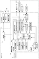
- FIG. 2 is a block diagram showing the configurations and functions of the user terminal 30 and the robot 1.
- the user terminal 30 is a mobile device such as a mobile phone or tablet, a personal computer, a notebook computer, or the like.
- the user terminal 30 is configured to be communicable with the robot 1 and includes a display unit that displays using an image signal transmitted from the robot 1.
- the user terminal 30 has a communication unit 31, a display unit 32, and an operation reception unit 33.
- the communication unit 31 communicates with an external device including the robot 1 and transmits / receives various signals.
- the communication unit 31 receives an image signal from the robot 1.
- the communication unit 31 transmits the user input information performed by the user U from the operation reception unit 33 to the robot 1 at the user terminal 30.
- the user terminal 30 in this embodiment includes a touch panel 35.
- the touch panel 35 includes a display device having a display unit 32 and a touch pad as a transparent operation reception unit 33 that covers the surface of the display device.
- the display device is composed of a liquid crystal panel, an organic EL panel, or the like, and displays an image on the display unit 32.
- the operation reception unit (touch pad) 33 has a detection function for detecting a position tapped by the user with a finger.
- the operation receiving unit 33 receives an input operation from the user.
- the operation receiving unit 33 is not limited to the touch pad, and may be a keyboard, a mouse, or the like, as long as the position on the image displayed on the display unit 32 designated by the user can be detected. good.
- An application (hereinafter, simply referred to as an application) that provides a function of making the learning status of the object recognition of the robot 1 visible by an image and a function of transmitting input information by the user to the robot 1 is installed in the user terminal 30. ..
- the application is started and the input operation is performed by tapping the input operation button displayed on the display unit 32.
- the user input information input by the user is transmitted to the robot 1 via the communication unit 31.
- the robot 1 includes a camera 2, a microphone 3, a speaker 4, an actuator 5, a vibration motor 6, a communication unit 7, and an information processing unit 10.
- the actuator 5 is provided at the joint portion and the connecting portion between the units.
- the position and orientation of the robot 1 are controlled, and the movement of the robot 1 is controlled.
- the camera 2 is mounted on the nose portion of the head unit 50.
- the position and orientation of the camera 2 change by controlling the movement of the robot 1 by driving the actuator 5. That is, the position and orientation of the camera 2 are indirectly controlled by driving and controlling the actuator 5, and the drive control signal of the actuator 5 can be said to be a drive control signal for controlling the position and orientation of the camera 2.
- the microphone 3 collects sounds around the robot 1.
- the speaker 4 emits sound.
- the vibration motor 6 is mounted on, for example, the body unit 51 of the robot 1.
- the vibration motor 6 generates vibration.
- the communication unit 7 communicates with an external device including the user terminal 30.
- the communication unit 7 transmits an image signal to the user terminal 30.
- the communication unit 7 receives the user input information from the user terminal 30.
- the information processing unit 10 includes a storage unit 8, an object model storage unit 9, a learning unit 20, a discriminator unit 15, a determination unit 16, a user input information acquisition unit 17, a user input information determination unit 18, and so on.
- a signal generation unit 19 and a model correction unit 21 are provided.
- the storage unit 8 includes a memory device such as a RAM and a non-volatile recording medium such as a hard disk drive, performs a process of generating a presentation signal presenting a learning status of object recognition, and various types performed based on user input information.
- a program for causing the robot 1 which is an information processing device to execute the process is stored.
- the processing in the information processing unit 10 is executed according to the program stored in the storage unit 8.
- the program stored in the storage unit 8 includes a step of performing recognition learning of an object in an image captured by the camera 2, a step of determining the progress status of the object recognition learning, and a target area and progress status of the object recognition learning. Is for causing the robot 1 which is an information processing apparatus to execute a step of generating a signal (hereinafter, sometimes referred to as a presentation signal) for presenting the user.
- a presentation signal a signal for presenting the user.
- the object model storage unit 9 stores an object model, which is data for recognizing an object.
- the object model storage unit 9 is configured to be able to read and write data.
- the object model storage unit 9 stores the object model learned and generated by the learning unit 20.
- the object model has object shape information such as a three-dimensional point group and learning state information.
- the learning state information includes the image that contributed to the learning, the degree of contribution, the distribution in the feature space, the spread, the overlap with the object model learned in the past, the position and orientation of the camera at the time of learning, and the like.
- the learning unit 20 performs learning processing using an object recognition algorithm.
- the learning unit 20 includes an image acquisition unit 11, an object area detection unit 12, a feature amount extraction unit 13, and a discriminator learning unit 14.
- the image acquisition unit 11 acquires an image taken by the camera 2.
- the image taken by the camera 2 may be referred to as a base image.
- the object area detection unit 12 detects an object area in which an object is presumed to exist from the image acquired by the image acquisition unit 11. This detection is executed by edge detection, background subtraction processing matching, or the like.
- the feature amount extraction unit 13 extracts the feature amount of the detected feature points from the detected object region.
- the feature points are detected by searching for a pixel pattern corresponding to a characteristic portion such as a corner portion of an object.
- a known method can be used as the feature extraction method. For example, pixel information corresponding to a feature point can be extracted as a feature amount.
- the discriminator learning unit 14 constructs an object model using the extracted feature amount information.
- the constructed object model is stored in the object model storage unit 9.
- the discriminator unit 15 discriminates an object in the image acquired by the image acquisition unit 11 by using the object model stored in the object model storage unit 9.
- the discriminator unit 15 compares the object in the image acquired by the camera 2 with the object model stored in the object model storage unit 9, and calculates a score based on the degree of similarity. A score of 0 to 1 is set as the score.
- the information obtained by discriminating the input image input from the camera 2 by the discriminator unit 15 includes the model part that contributed to the discrimination, the model part that adversely affected the discrimination, and a part of the input image. Includes information such as statistics on the situation of.
- the information obtained by discriminating the input image by the discriminator unit 15 may be referred to as discrimination trial result information.
- the discrimination trial result information is the discrimination result.
- the determination unit 16 determines the learning situation using the determination trial result information.
- the learning status includes information on the target area of object recognition learning (hereinafter sometimes referred to as learning target area) and the progress status of object recognition learning in the learning target area (hereinafter sometimes referred to as learning progress status). Contains information.
- learning target area the target area of object recognition learning
- learning progress status the progress status of object recognition learning in the learning target area
- Contains information an example is given in which the learning progress is judged by two values of whether or not learning has been completed.
- the object area estimated to be the object area by the object area detection unit 12 during the learning process is the area to be learned
- the object area detected by the object area detection unit 12 is determined to be the learned area.
- a region that is not detected as an object region may be determined as an unlearned region.
- the user input information acquisition unit 17 as an input information acquisition unit acquires the user input information transmitted from the user terminal 30 via the communication unit 7. Further, when the input operation by the voice of the user U is performed, the user input information acquisition unit 17 acquires the voice information of the user U collected by the microphone 3 as the user input information.
- the user input information as input information includes content information of processing such as "learning start”, “additional learning”, and “exclusion", and area information of a target to be processed.
- the user input information determination unit 18 determines the user input information acquired by the user input information acquisition unit 17.
- the function of the user input information determination unit 18 in the case of user input from the touch panel 35 will be described.
- the image captured by the camera 2 of the robot 1 can be displayed on the display unit 32 of the user terminal 30, and the user involved in learning such as "start learning”, “additional learning", and “exclusion”.
- Input buttons for input operations from can be displayed.
- the input operation from the user is performed by tapping the input buttons such as "learning start”, “additional learning", and "exclusion” displayed on the display unit 32 of the touch panel 35 of the user terminal 30.
- the user input information determination unit 18 determines whether the input user input information is "learning start", “additional learning", or "exclusion".
- the area to be additionally learned or excluded is designated by the input operation from the touch panel 24 before the input by these buttons.
- “exclusion” is an area learned by the robot 1, but an area that does not need to be learned and can be ignored is excluded from the object model.
- a specific image display example on the user terminal 30 will be described later.
- a predetermined area centered on the position tapped by the finger may be used as the additional learning or exclusion area.
- the segment including the tapped position may be an area for additional learning or exclusion.
- the user input information determination unit 18 determines whether or not to change the position and orientation of the camera 2.
- the user input information determination unit 18 calculates the position / orientation information of the camera 2 when changing the position / orientation of the camera 2.
- the user input information determination unit 18 determines that "learning has started"
- the user input information determination unit 18 transmits instruction information for starting learning to the learning unit 20.
- the learning unit 20 the learning process is executed based on the instruction to start learning.
- the user input information determination unit 18 is "additional learning", and when it is determined that the position and orientation of the camera 2 is changed, the area information of the additional learning designated by the user U is transmitted to the learning unit 20 and calculated.
- the position / orientation information of the camera 2 is transmitted to the signal generation unit 19.
- the control signal generation unit 191 of the signal generation unit 19 generates a drive control signal for the actuator 5 based on the position / orientation information of the camera 2.
- the learning process is executed based on the instruction of the additional learning.
- the feature amount of the designated additional learning area of the image taken by the camera 2 after the position / orientation change is extracted, and the object model is reconstructed using the feature amount.
- the reconstructed object model is stored in the object model storage unit 9.
- the user input information determination unit 18 is "additional learning", and if it determines that the position and orientation of the camera 2 are not changed, the user input information determination unit 18 transmits the area information of the additional learning designated by the user U to the learning unit 20.
- the learning unit 20 the feature amount of the designated additional learning area is extracted based on the instruction of the additional learning, and the object model is reconstructed using the feature amount.
- the reconstructed object model is stored in the object model storage unit 9.
- the user input information determination unit 18 determines that the information is "excluded"
- the user input information determination unit 18 transmits the information of the exclusion area specified by the user U to the model correction unit 21.
- the model modification 21 will be described later.
- the function of the user input information determination unit 18 in the case of user input by the user's voice will be described.
- the user input information determination unit 18 is an instruction to start learning or an instruction to move the robot 1 based on the user's voice information collected by the microphone 3 and acquired by the user input information acquisition unit 17. Determine if there is. A specific example of the user's voice input operation will be described later.
- the user input information determination unit 18 determines whether or not the user has spoken a keyword that triggers the start of learning, based on the voice information of the user U. When it is determined that the word has been spoken, the learning start instruction information is transmitted to the learning unit 201. In the learning unit 20, the learning process is executed based on the instruction of the additional learning.
- keywords for example, words such as “start learning”, “learning”, and “remember” can be used. These keywords are preset and stored.
- the user input information determination unit 18 determines whether or not the user has spoken a keyword instructing the movement of the robot 1 based on the voice information acquired by the user input information acquisition unit 17. When it is determined that the word has been spoken, the user input information determination unit 18 calculates the position / posture information of the robot 1 so that the robot moves according to the content of the keyword. The user input information determination unit 18 transmits the calculated position / orientation information of the robot 1 to the signal generation unit 19. The control signal generation unit 192 of the signal generation unit 19 generates a drive control signal for the actuator 5 based on the position / orientation information of the robot 1. By driving the actuator 5 based on the generated drive control signal, the position and orientation of the robot 1 and eventually the position and orientation of the camera 2 are changed.
- Keywords for example, a word consisting of a combination of words indicating directions such as “right”, “left”, “up” and “down” and words indicating the action contents such as “move”, “turn” and “look”.
- Keywords are preset and stored.
- the drive control signal is generated based on the content of the keyword, which is a combination of the direction and the operation content. For example, suppose that the user U instructs the robot 1 that has started learning and is in the learning mode to "turn to the left".
- the user input information determination unit 18 calculates motion information for changing the position and posture so that the robot 1 turns to the left of the object to be learned and faces the object according to the instruction content of the user.
- the signal generation unit 19 generates a presentation signal that presents the learning status to the user based on the learning status determined by the determination unit 16.
- the learning status presentation method includes an image display by the user terminal 30, an action display by the robot 1, a voice display by the robot 1, and the like.
- the signal generation unit 19 includes an image signal generation unit 191, a control signal generation unit 192, and an audio signal generation unit 193.
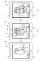
- FIG. 3 is an example of an image displayed on the display unit 32 of the user terminal 30 during learning of the robot 1.
- FIG. 3A shows an image displayed when the application is started.
- FIG. 3B shows an image in which the learning situation is presented.
- FIG. 3C shows an image showing a learning situation after learning based on additional learning and exclusion instructions given by the user by looking at the image shown in FIG. 3B.
- the object recognition learning target of the robot 1 is the pot 40.
- the image signal generation unit 191 generates an image signal to be displayed on the display unit 32 of the user terminal 30.
- the image signal can be a presentation signal that presents the learning situation.
- the display unit 32 of the user terminal 30 has a base image or a robot acquired by the camera 2 of the robot 1 generated by the image signal generation unit 191. An image in which the learning situation of 1 is visualized is displayed. Further, an input button or the like is displayed on the display unit 32.
- the image signal generation unit 191 generates a superimposition image based on the determination result of the determination unit 16.
- the image signal generation unit 191 generates a display image in which a superimposition image representing a learning situation is superimposed on the base image.
- the generated image signal can be a presentation signal that presents the learning situation.
- a display image in which the overlay image of the rectangular tile 60 is superimposed on the base image on which the jar 40 is projected is displayed.
- the display of the tile 60 indicates the learning target area and the learning progress status that the area is being learned.
- the area where the tile 60 is not displayed indicates that the area is not a learning target area but an unlearned area.
- the size and shape of the tile 60 are not limited.
- the tile 60 representing the learning situation is generated based on the judgment result in the judgment unit 16. In this way, the learning situation can be presented to the user by displaying the image. The user can intuitively grasp the learning status of the robot 1 by looking at the image displayed on the display unit 32.
- the control signal generation unit 192 generates a drive control signal for controlling the drive of the actuator 5 of the robot 1.
- the drive control signal can be a presentation signal that presents a learning situation.
- the orientation of the head unit 50 of the robot 1 on which the camera 2 is mounted with respect to the object to be learned for object recognition indicates to the user where the learning target area is. That is, the portion of the object to be learned that faces the head unit 50 is the area to be learned. In this way, the position and orientation of the robot 1 can be used to present the learning target area, which is one of the learning situations, to the user.
- the user can intuitively grasp the area that the robot 1 is learning by looking at the position and posture of the robot 1.
- the control signal generation unit 192 drives the actuator 5 to move the robot 1 to a position suitable for image acquisition in the additional learning area based on the additional learning area information transmitted from the user input information determination unit 18. Generate a control signal.
- the control signal generation unit 192 generates a drive control signal for the actuator 5 based on the position / orientation information of the robot 1 transmitted from the user input information determination unit 18.
- the control signal generation unit 192 may generate a drive control signal based on the determination result of the determination unit 16. For example, the drive control signal of the actuator 5 may be generated such that the tail is shaken when it has not been learned and the tail is not shaken when it has been learned. In this way, the position and posture of the robot 1 may be controlled, and the learning progress status, which is one of the learning statuses, may be presented to the user by displaying the behavior of the robot 1. The user can intuitively grasp the learning progress status of the robot 1 by observing the behavior of the robot 1.
- control signal generation unit 192 may generate a drive control signal for controlling the vibration of the vibration motor 6 based on the determination result of the determination unit 16.
- the drive control signal of the vibration motor 6 may be generated so as to generate vibration when it has not been learned and not to generate vibration when it has been learned.
- the learning progress status which is one of the learning statuses, may be presented to the user by the action display of the robot 1 indicated by the vibration. The user can intuitively grasp the learning progress status of the robot 1 by observing the behavior of the robot 1.
- the audio signal generation unit 193 generates an audio signal.
- the speaker 4 emits a voice based on the generated voice signal.
- the audio signal can be a presentation signal that presents the learning situation.
- a voice imitating the bark of a dog is emitted as a voice.
- the audio signal generation unit 193 may generate an audio signal based on the determination result of the determination unit 16. For example, it is possible to generate a voice signal so as to raise a bark when it has not been learned and not to raise a bark when it has been learned. In this way, the learning progress status, which is one of the learning statuses, can be presented to the user by the voice display. The user can intuitively grasp the learning progress status of the robot 1 by listening to the voice emitted from the robot 1.
- the model correction unit 21 modifies the object model stored in the object model storage unit 9 based on the exclusion area information specified by the user U received from the user input information determination unit 18.
- the modified object model is stored in the object model storage unit 9.
- FIG. 4 is a time flowchart showing a flow of a series of processes related to the presentation of the learning situation by displaying the image of the robot 1.
- the dotted line portion in FIG. 4 is an operation performed by the user U of the user terminal 30, and the solid line portion in the figure is a process performed by the user terminal 30 and the robot 1.
- the information processing method related to the presentation of the learning situation by image display and the additional learning and exclusion based on the user instruction will be described with reference to FIG.
- the robot 1 acquires image information captured by the camera 2 by the image acquisition unit 11 (ST1).
- the robot 1 sends an image signal (image information) acquired by the image acquisition unit 11 to the user terminal 30 (ST2).
- the user terminal 30 receives the image signal (ST3).
- the user terminal 30 displays an image on the display unit 32 using the received image signal (ST4).
- On the display unit 32 for example, as shown in FIG. 3A, an image in which the input button 65 for starting learning is superimposed on the base image captured by the camera 2 of the robot 1 is displayed.
- the user terminal 30 receives the learning start instruction (ST5).
- the user terminal 30 sends the learning start instruction to the robot 1 (ST6).
- the learning unit 20 starts the object recognition learning of the pot 40 (ST8).
- the learning process will be described later.
- the robot 1 generates an image signal that presents the learning situation in the image signal generation unit 191 (ST9).
- the image signal is an image in which a superimposition image showing a learning situation is superimposed on a base image.
- the image signal generation process will be described later.
- the robot 1 transmits the generated image signal to the user terminal 30 (ST10).
- the user terminal 30 receives the image signal (ST11) and displays the image on the display unit 32 using the image signal (ST12).
- the image signal received by the user terminal 30 is an image in which the tile 60, which is a superimposing image showing the learning situation, is superimposed on the base image on which the jar 40 to be learned is projected.
- the learning status includes learning target area information and learning progress status.
- an example of displaying the learning progress status as a binary value of whether or not the learning has been completed will be given. That is, the position where the tile 60 is arranged indicates the learning target area information, and the presence or absence of the display of the tile 60 indicates the learning progress status.
- the display unit 32 displays the additional learning input button 66 and the exclusion input button 67 superimposed on the image based on the received image signal.
- the learning situation is visualized and presented to the user by displaying the tile 60.
- the area where the tile 60 is not displayed is the unlearned area of the robot 1.
- the vicinity of the region surrounded by the broken circle 71 located below the jar 40 is an unlearned region in the object recognition learning of the jar 40.
- This unlearned region is, for example, the region of the jar 40, but is not presumed to be the object region by the object region detection unit 12.
- the area surrounded by the broken line circle 70 which is learned by the robot 1 but is not the area of the jar 40, is not the area of the jar 40, but is estimated to be the object area by the object area detection unit 12. Is.
- the area around the area surrounded by the circle 70 is an area that should be ignored when recognizing the jar 40 as an object, and is an area that is excluded in the object model.
- a predetermined area centered on the tapped position becomes a target area for additional learning or exclusion.
- the additional learning input button 66 or the exclusion input button 67 is tapped, so that the user terminal 30 receives the user input information (S13). ..
- the user input information can be rephrased as feedback information from the user.
- the user U taps an arbitrary part of the area surrounded by the circle 71, and further, by tapping the input button 66 for additional learning, an instruction for additional learning and the area thereof.
- the information is accepted as user input information.
- the user U taps an arbitrary part of the area surrounded by the circle 70, and further taps the exclusion input button 67, so that the exclusion instruction and the area information are accepted as the user input information.
- the area has already been learned, if the user U determines that it is an area that he / she wants to learn further, the area is tapped and the input button 66 for additional learning is tapped. Therefore, it can be set as a target area for additional learning.
- the user U can specify the area where the learning is insufficient, the area where the learning is desired to be focused, and the area to be excluded by the input operation from the touch panel 35 by looking at the learning situation presented by the image display. ..
- the user terminal 30 sends the user input information to the robot 1 (ST14).
- the robot 1 acquires user input information at the user input information acquisition unit 17 via the communication unit 7 (ST15). Next, the robot 1 determines the user input information by the user input information determination unit 18 (ST16). Specifically, the user input information determination unit 18 determines whether the user input information is additional learning or exclusion. When the user input information determination unit 18 determines that the additional learning is performed, the user input information determination unit 18 determines whether or not to change the position and orientation of the camera 2 based on the additional learning area information. When the user input information determination unit 18 determines that the position / orientation of the camera 2 is changed, the user input information determination unit 18 calculates the position / orientation information of the camera 2 suitable for acquiring the image of the designated additional learning area. For example, when the robot 1 is provided with a depth sensor, the position / orientation information of the camera 2 may be calculated using the distance information between the object to be recognized and the robot 1 in addition to the image information acquired by the camera 2.
- the robot 1 generates various signals, learns, modifies the object model, and the like according to the determination result in the user input information determination unit 18 (S17).
- the signal generation and learning in S17 when it is determined in S16 that the position and orientation of the camera 2 are changed due to the additional learning will be described.
- the position / orientation information of the camera 2 calculated by the user input information determination unit 18 is transmitted to the signal generation unit 19.
- the control signal generation unit 192 of the signal generation unit 19 generates a drive control signal for the actuator 5 based on the received position / orientation information of the camera 2.
- the actuator 5 is driven based on the generated drive control signal, and the position and orientation of the camera 2 are changed.
- the same learning process as in ST8 is performed. Specifically, learning is performed by the learning unit 20 using the image acquired by the camera 2 whose position and orientation have changed.
- feature amount extraction and discriminator learning of the additional learning area designated for the additional learning are performed, and the object model is reconstructed.
- the reconstructed object model is stored in the object model storage unit 9.
- the learning in S17 when it is determined in S16 that the position and orientation of the camera 2 is not changed due to the additional learning will be described.
- the area information of the additional learning is transmitted to the learning unit 20.
- the learning unit 20 learns the area designated for the additional learning.
- the learning unit 20 reconstructs the object model by extracting the feature amount of the region designated for the additional learning and learning the discriminator.
- the reconstructed object model is stored in the object model storage unit 9.
- the exclusion in S17 when it is determined in S16 that the region is excluded will be described.
- the exclusion area information is transmitted to the model correction unit 21.
- the model correction unit 21 corrects the object model by excluding the designated area.
- the modified object model is stored in the object model storage unit 9.
- the robot 1 generates a display image displayed on the display unit 32 of the user terminal 30.
- an image signal is generated based on the additional learning and exclusion instructions. That is, since the robot 1 excludes the region of the circle 70 shown in FIG. 3 (B) from the learning target region and additionally learns the region of the circle 71, it substantially covers the pot 40 as shown in FIG. 3 (C). The tiles 60 are superimposed in this manner, and an image excluding the display of the tiles 60 in the area corresponding to the circle 70 is generated. In this way, the result of performing additional learning or the like based on the feedback information from the user U is reflected, and an image in which the change in the learning situation is visualized again is presented to the user U.
- the user can see the image in which the change in the learning situation is visualized again, and give feedback such as additional learning and exclusion again.
- the object model can be optimized by repeatedly performing feedback from the user U who is presented with the learning status and additional learning or the like in response to the feedback.
- the learning process of ST8 requires a long time, the information that learning is in progress may be presented to the user by displaying an image. In this case, when the learning is completed, the processing after ST9 may be performed.
- the image acquisition unit 11 acquires the image captured by the camera 2 (ST80).
- the object area detection unit 12 detects an object area in which an object is presumed to exist from the image acquired by the image acquisition unit 11 (ST81).
- the feature amount extraction unit 13 extracts the feature amount of the detected feature points from the detected object region (ST82).
- the discriminator learning unit 14 constructs an object model using the extracted feature amount information.
- the constructed object model is stored in the object model storage unit 9 (ST82).
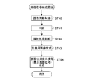
- the image acquisition unit 11 acquires the image captured by the camera 2 (ST90).
- the discriminator unit 15 discriminates the object in the acquired image using the object model stored in the object model storage unit 9 (ST91).
- the determination unit 16 determines the learning status of object recognition based on the determination result of the discriminator unit 15 (ST92).
- the determination unit 16 determines the learning target area and the learning progress status of the area as the learning status.
- the learning progress status is determined by two values of whether or not learning has been completed.
- the image signal generation unit 191 generates a superimposition image based on the learning situation determined by the determination unit 16 (ST93).
- an image of the tile 60 is generated as a superimposing image showing the learning situation.
- the display of the tile 60 indicates the learning target area and the learning progress status of being learned.
- the image signal generation unit 191 generates a display image signal in which the tile 60, which is an overlay image, is superimposed on the base image (ST94).
- the display image signal is a presentation signal that presents the learning status to the user U.
- the learning status of the robot 1 can be presented to the user U by displaying an image.
- the user U can visually and intuitively grasp the learning situation of the robot 1 by looking at the image, and can grasp the growth state of the robot 1. Further, the user U can instruct additional learning of the unlearned area and exclusion of the area that does not need to be learned by looking at the displayed image. Since the robot 1 can perform additional learning and eliminate areas unnecessary for the object model according to instructions from the user, the object model can be optimized efficiently, and the performance in object recognition can be efficiently improved. Can be done. Further, by performing additional learning or the like according to the instruction by the user U, the user U can have a simulated experience of disciplining a real animal.
- FIG. 7 is a diagram illustrating the presentation of the learning situation by the display in the position and posture of the robot 1 and the voice display.
- the object of object recognition learning is a PET bottle 41 of tea.
- FIG. 7A shows a state when the user U gives an instruction to start learning, and the robot 1 is in an unlearned state.
- FIG. 7B shows how the robot 1 has already learned.
- FIG. 7C shows how the user U instructs additional learning.
- FIG. 7A shows a state when the user U gives an instruction to start learning, and the robot 1 is in an unlearned state.
- FIG. 7B shows how the robot 1 has already learned.
- FIG. 7C shows how the user U instructs additional learning.
- FIG. 8 is a time flowchart showing a flow of a series of processes related to the display of the robot 1 in the position and posture and the presentation of the learning situation by the voice display.
- the dotted line portion in FIG. 8 is an operation performed by the user U, and the solid line portion in the figure is a process performed by the robot 1.
- the information processing method related to the presentation of the learning situation by the display in the position and posture of the robot 1 and the voice display will be described with reference to FIG. 7.
- the camera 2 of the robot 1 is always activated and is in a state where image acquisition is possible.
- the user U arranges the PET bottle 41 in front of the robot 1 so that the PET bottle 41 to be the object recognition learning is located in the shooting field of view of the camera 2 of the robot 1.
- the robot 1 is input with the start instruction of the object recognition learning of the PET bottle 41.
- the speech of the user U is collected by the microphone 3.
- This voice information is acquired as user input information by the user input information acquisition unit 17 (ST20).
- the user input information determination unit 18 performs voice recognition processing of the acquired voice information (ST21), and determines whether or not a word instructing the start of learning has been made.
- a word is made to instruct the start of learning.
- the user input information determination unit 18 calculates the position / orientation information of the camera 2 capable of acquiring the image of the PET bottle 41 suitable for the object recognition learning.
- the position suitable for object recognition learning is, for example, a position where the entire PET bottle 41 fits within the shooting field of view of the camera 2. If the camera 2 is already in a position and orientation suitable for object recognition learning, the position and orientation of the camera 2 is maintained.
- the control signal generation unit 192 generates a drive control signal for the actuator 5 based on the position / orientation information of the camera 2 calculated by the user input information determination unit 18 (ST22).
- the position and orientation of the robot 1 and the position and orientation of the camera 2 change.
- the area of the PET bottle 41 facing the robot 1 is the learning target area, and the user U can grasp the area targeted by the robot 1 by observing the positional relationship between the robot 1 and the PET bottle 4. In this way, the learning target area is presented to the user U depending on the position and orientation of the robot.
- the drive control signal of the actuator 5 that controls the position and orientation of the camera 2 is a presentation signal that presents the learning target area to the user.
- the learning unit 20 starts the object recognition learning of the PET bottle 41 (ST8). Since this learning process is the same as ST8 of the first embodiment, the description thereof will be omitted.
- the audio signal generation unit 193 generates an audio signal indicating the learning progress status (ST23).
- the audio signal generation process will be described later.
- the generated voice signal is a presentation signal that presents the learning progress status to the user, and the speaker 4 emits a voice based on the voice signal (S24).
- the robot 1 can generate a voice signal so as not to make a bark when it has not been learned and to not make a bark when it has been learned.
- the learning progress status which is one of the learning statuses
- the presentation of the learning target area which is one of the learning situations, to the user is performed by displaying the robot 1 in the position and posture with respect to the learning target object.
- User U can determine that the robot 1 has already learned by observing how the robot 1 no longer makes a bark.
- the user U can instruct the robot 1 to move to a position for capturing an image of the area to be additionally learned by speaking.
- FIG. 7C when the user U utters "turn to the left", a movement instruction input to a position for taking an image of an area to be additionally learned is made.
- the microphone 3 collects the words of the user U.
- This voice information is acquired as user input information by the user input information acquisition unit 17 (ST25).
- the user input information determination unit 18 performs voice recognition processing of the acquired voice information (ST26), and determines whether or not a word instructing the movement of the robot 1 is being made.
- the utterance instructing this movement is feedback information from the user U that specifies an area for additional learning.
- the word "turn left” is used to indicate the movement of the robot 1.
- the user input information determination unit 18 calculates the position / posture information of the robot 1 so that the robot moves according to the content of the keyword being spoken.
- the control signal generation unit 192 generates a drive control signal for the actuator 5 based on the position / orientation information of the robot 1 calculated by the user input information determination unit 18 (ST27).
- ST27 the user input information determination unit 18
- the process is repeated by returning to ST8, and object recognition learning of the PET bottle 41 is performed from different viewpoint positions.
- the object model is constructed and optimized.
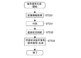
- the image acquisition unit 11 acquires the image captured by the camera 2 (ST230).
- the discriminator unit 15 discriminates the object in the acquired image using the object model stored in the object model storage unit 9 (ST231).
- the determination unit 16 determines the learning status of object recognition based on the determination result of the discriminator unit 15 (ST232).
- the determination unit 16 determines the area information of the learning target and the learning progress status information of the area as the learning status.
- the learning progress status is judged by two values of whether or not learning has been completed.
- the audio signal generation unit 193 generates an audio signal indicating the learning progress status based on the learning status determined by the determination unit 16 (ST233).
- a voice signal imitating the bark of a dog is generated as a voice signal indicating the learning progress status. For example, if it has not been learned, it will bark "one-one-one", and if it has been learned, it will not bark.
- the bark (voice) may be changed to express the case where learning is not performed at all and the case where learning is being performed.
- the bark (voice) can be changed depending on the volume and the frequency of barking.
- the learning situation can be presented to the user by using the voice display which is one of the communication means provided in the robot 1.
- a movement instruction is input from the user, the actuator is driven according to the instruction, and then learning is executed. Not limited to this.
- the learning after the position / posture change may be performed by the instruction of uttering "learning start”.
- the learning mode may be switched to the normal mode by the user's utterance of "learning end”.
- Such a keyword indicating the end of learning may be registered in advance, and the presence or absence of a word indicating the end of learning from the user may be determined by voice recognition using the registered keyword.
- the robot 1 excludes the region that was the object recognition target when the word was spoken from the object model.
- a keyword indicating such exclusion processing may be registered in advance, and the presence or absence of a word meaning exclusion from the user may be determined by voice recognition using the registered keyword.
- the learning status of the robot 1 can be presented to the user U by the display in the position and posture of the robot 1 and the voice display emitted from the robot 1.
- the user U can intuitively grasp the learning situation of the robot 1 by observing the behavior of the robot 1, and can grasp the growth state of the robot 1.
- the user U can give an instruction for additional learning of the unlearned area, and the robot 1 can move and learn according to the instruction, so that the object model can be optimized efficiently.
- the user U can give an instruction related to learning to the robot 1 by a voice instruction, it is possible to have a simulated experience of disciplining a real animal.
- the learning status is tiled, but as shown in FIG. 10, the learning status may be displayed using the icon 61.
- the icon 61 is a camera icon that schematicallys the viewpoint information.
- the shape of the icon can be various, such as the shape of a robot.
- the image signal generation unit 191 When the object model has three-dimensional information and the viewpoint learned at the time of learning is recorded, the image signal generation unit 191 has the learning that the object model has in addition to the determination result in the determination unit 16.
- an icon 61 indicating the learning viewpoint may be generated as a superimposing image according to the posture of the object currently being captured.
- the position of the icon 61 in the shape of the camera on the image and the orientation of the camera indicate the area to be learned by the robot 1 with respect to the pot 40, and indicate that the area has been learned.
- the icon 61 as the superimposing image may be superposed on the pot 40 in the base image to generate a display image showing the learning status.
- the display method such as changing the color of the icon 61 or blinking it, it is possible to express the learning as being distinguished from the learned, and the tile display of the first embodiment, the sixth described later. The same applies to the voxel display of the embodiment.
- the input button for starting learning is displayed on the base image acquired by the camera 2, and the input operation is performed from the input button. Learning begins.
- the input buttons for additional learning and exclusion may be displayed on the image on which the icon 61 is superimposed, as in the first embodiment.
- the image may be displayed as a thumbnail.
- the image acquired by the camera 2 may be divided into a plurality of images and displayed as thumbnails, and the frame 63 may be used as a superimposing image showing the learning status.
- the frame 63 has a shape surrounding the thumbnail image 62, and when the area indicated by the thumbnail image 62 has been learned, the frame 63 is superimposed and displayed so as to surround the thumbnail image 62.
- the area shown by the thumbnail image 62 not surrounded by the frame 63 indicates that it has not been learned.
- the input button for starting learning is displayed on the base image acquired by the camera 2, and the input operation is performed from the input button. Learning begins.
- additional learning / exclusion input buttons may be displayed on the thumbnail-displayed image. By tapping an arbitrary thumbnail image by the user and tapping the input button for additional learning or exclusion, additional learning or exclusion of the thumbnail image tapped by the user is performed.
- the thumbnail display may be used to indicate to the user U that learning is in progress.
- the image of the object area estimated and detected by the robot 1 is divided and displayed as thumbnails.
- the frame 63 is not superimposed on the thumbnail image 62 being learned, and the frame 63 is superimposed and displayed on the learned thumbnail image 62.
- the user U can grasp the progress of learning.
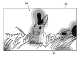
- the learning situation may be displayed as a heat map.
- the heat map is map information in which the position of the learning target area in the image and the learning progress status are associated with each other, and is displayed by using the difference in color including the shade of color.
- the example in which the learning progress status is expressed by two values of whether or not the learning progress is being learned is given, but it may be three or more values.
- an example of displaying the learning progress status as a heat map with four values will be described, but the heat map may be displayed with two values.
- a superimposition image is generated so that the area to be learned can be identified by color, and the area not to be learned is not colored.
- the heat map of the superimposed image is shown in three different colors according to the learning progress.
- the difference in color of the heat map 64 is shown by dot display.
- the denser the dot density is, the more the learning is done.
- the part having the densest dot density shows red
- the part having the next densest dot density shows green
- the part having the coarsest dot density shows blue.
- the colors used for the heat map display are not limited to the colors described here.
- the heat map display allows the user to intuitively grasp the learning progress.
- the learning situation is determined by the determination unit 16 using the score which is the determination result output by the determination unit 15. Based on the judgment result, the color display of the heat map showing the learning progress is determined.
- the determination unit 16 determines the learning progress status based on the score calculated by the discriminator unit 15. For example, if the score is greater than 0.5, the determination unit 16 determines that learning has been sufficiently performed.
- the determination unit 16 transmits the position information of the region having a score greater than 0.5 and the color information indicating the region in red in the superimposing image to the image signal generation unit 191. When the score is 0.3 or more and 0.5 or less, the judgment unit 16 determines that the learning progress is moderate.
- the determination unit 16 transmits the position information of the region having a score of 0.3 or more and 0.5 or less and the color information indicating that the region in green in the superimposing image to the image signal generation unit 191. If the score is 0 or more and less than 0.3, it is judged that the learning is insufficient. The determination unit 16 transmits to the image signal generation unit 191 the position information of the region having a score of 0 or more and smaller than 0.3 and the color information indicating the region in the superimposing image in blue.
- the image signal generation unit 191 generates a superimposition image based on the information transmitted from the determination unit 16, and the superimposition image is superposed on the base image to generate a display image to be displayed on the display unit 32.
- a heat map 64 showing a learning situation is superimposed as an overlay image on the base image of the rabbit 42 to be recognized as an object.
- the vicinity of the right ear of the rabbit 42 is displayed in red, a green region is arranged so as to surround the red portion, and a blue region is further arranged so as to surround the green region.
- the heat map 64 that visualizes the learning progress data is displayed in different colors according to the score.
- the learning progress may be expressed by three or more values, and the score may be used to generate a heat map quantized with some threshold values.
- the continuous value of the score is quantized and displayed in different colors, but the continuous value may be expressed by, for example, a shade of color.
- the learning progress status is presented with three or more values. You can also do it. Specifically, based on the judgment of the learning progress status based on the score calculated by the discriminator unit 15 made by the judgment unit 16, the volume and length of the voice emitted from the robot 1 and the frequency of voice generation are generated. Can be changed. For example, an audio signal may be generated so that the bark becomes smaller as the learning progresses, or an audio signal may be generated so that the bark gradually disappears as the learning progresses, although it was barking at the beginning of the learning. In this way, the learning progress status can be displayed with three or more values even in the voice display.
- the input button for starting learning is displayed on the base image acquired by the camera 2, and the input operation is performed from the input button. Learning begins.
- the input buttons for additional learning and exclusion may be displayed on the image on which the heat map 64 is superimposed, as in the first embodiment. By tapping any part of the display unit 32 by the user and tapping the input button for additional learning or exclusion, additional learning or exclusion of the area tapped by the user is performed. When an arbitrary portion in the region on which the heat map 64 is superimposed is tapped, an region having the same color as the tapped portion may be subject to additional learning or exclusion.
- the image signal generation unit 191 superimposes the object using the estimated position and orientation of the object in addition to the determination result of the determination unit 16 as shown in FIG.
- a three-dimensional voxel 68 may be generated as an image for use. In this way, the learning situation may be displayed using the three-dimensional voxels 68.
- the object recognition learning situation can be presented to the user by images, the position and orientation of the robot, the voice emitted from the robot, and the like.
- the user can intuitively grasp the learning situation visually, audibly, or the like.
- the user can experience a realistic interaction with the robot.
- the heat map shows the number of times of repeated learning for each viewpoint or area, the degree of decrease in cost value, etc. as the learning situation. It may be superimposed and displayed as such.
- the heat map display such as the number of repeated learnings and the degree of reduction in the cost value may be displayed on a color axis different from the heat map display showing the learning progress status of the fifth embodiment. Further, the number of times of repeated learning and the degree of decrease in the cost value may be expressed by making the color transmittance of the heat map showing the learning progress of the fifth embodiment different.
- the unlearned area may be blurred and displayed, or the image may be displayed so as to be coarse. Further, as the superimposing image showing the learning progress status, an image or the like in which the score information is written in characters may be used. Further, the learned area may be displayed as an outline.
- an image area in which the object area detection unit 12 is uncertain about whether or not to use the object area may be visualized and displayed so as to be recognizable by the user.
- the user U may instruct whether or not the robot 1 should learn the image region that is difficult to discriminate by looking at this image.
- efficient learning can be performed.
- the present invention is not limited to this.
- the user U may change the position and posture of the camera 2 by directly moving the limbs of the robot 1.
- the input operation may be input by a characteristic gesture performed by the user.
- the user's gesture can be recognized from the image taken by the camera 2 or the rear camera.
- the user U is located behind the robot 1, the user's gesture can be recognized from the image taken by the rear camera of the robot 1.
- the camera that captures the image for performing the gesture recognition of the user U and the camera that captures the image of the object to be the object recognition learning are different.
- a characteristic gesture performed by the user may trigger the start of learning.
- the gesture to be the trigger is predetermined, and the user input information determination unit 18 recognizes the gesture using the image taken by the camera 2, and learns assuming that the user has performed an input operation for starting learning. May be started.
- the action instruction of the robot 1 by the user may be given by a gesture.
- the robot 1 may be configured to move to the left by a gesture in which the user extends the left hand horizontally from the center of the chest to the left side. Such gestures are pre-registered.
- the above-mentioned example of starting learning triggered by a keyword is given, but the present invention is not limited to this.
- the sound of clapping a hand, the sound of a musical instrument such as a flute, music, or the like may be configured to trigger the start of learning.
- the trigger for starting learning is not limited to the input operation from user U.
- the robot 1 recognizes by image recognition that it is an unknown object other than the object memorized so far, the learning for the unknown object may be started.
- the learning may be started by taking a specific position and posture such that the object to be learned by the user U is placed on the front leg of the robot 1, for example.
- the drive signal of the actuator 5 of the robot 1 may be generated so as to change the object held by the robot 1 based on the input from the touch panel 35 or the voice input by the user U.
- the viewpoint of the camera with respect to the object changes, and the object can be photographed from a different viewpoint.
- the robot 1 and the object may be arranged so that the object to be learned and the known object are located in the shooting field of view of the camera 2.
- the robot 1 can estimate the scale of the learning target object using the known object.
- the known object is an object that the robot 1 stores in advance, and is, for example, a toy such as a ball dedicated to the robot.
- a learning situation is presented by an image display and an instruction is given to the robot 1 by an input operation from the touch panel 35 on which the image is displayed.
- the learning situation is presented by the display in the position and posture of the robot 1 and the voice display, and the instruction to the robot 1 is given by the voice of the user U.
- the robot 1 is provided with an information processing unit 10 that performs a series of processes for generating a presentation signal, but the robot 1 is provided with an external device other than the robot 1 such as a server or a user terminal 30. May be good.
- the external device provided with the information processing unit 10 is the information processing device.
- some functions of the information processing unit 10 may be provided in an external device other than the robot 1.
- the image signal generation unit 191 may be provided on the user terminal 30 side.
- the quadrupedal pet-type robot has been described as an example of the robot, but the present invention is not limited to this. It may be provided with two-legged or two-legged or more multi-legged walking or other means of transportation.
- a camera control signal for controlling the optical mechanism of the camera may be generated based on the input information in the additional learning area.
- the present technology can have the following configurations.
- a learning unit that recognizes and learns objects in images taken by a camera, A judgment unit that judges the progress of recognition learning of the target area of the object,
- An information processing device including a signal generation unit that generates a presentation signal that presents the target area and the progress status to the user.
- the signal generation unit is an information processing device that generates an image signal that visualizes the target area and the progress status as the presentation signal.
- the signal generation unit is an information processing device that generates an image signal in which an image taken by the camera is superposed with a superimposition image representing the target area and the progress status.
- the superimposed image is an information processing device that is an image represented by using at least one of a heat map, tiles, voxels, characters, and icons.
- the signal generation unit is an information processing device that generates an image signal by superimposing a superimposition image showing the progress of recognition learning on a thumbnail image obtained by dividing the image.
- the signal generation unit is an information processing device that generates an audio signal indicating the progress status as the presentation signal.
- the signal generation unit generates a control signal for controlling the position and orientation of the moving body on which the camera is mounted as the presentation signal.
- the target area is an information processing device presented to the user according to the positional relationship between the moving body and the object.
- the information processing device according to any one of (1) to (7) above. Further provided with a discriminator unit for discriminating an object in the image using the object model generated by the learning unit. The judgment unit judges the progress status by using the judgment result of the discriminator unit.
- the signal generation unit is an information processing device that generates the presentation signal using the determination result of the determination unit.
- An information processing device further comprising an input information acquisition unit for acquiring input information by the user for the presentation content based on the presentation signal.
- the learning unit is an information processing device that performs object recognition learning based on the input information.
- the signal generation unit is an information processing device that controls the position and orientation of the camera based on the input information.
- the information processing device according to (9) above. An information processing device further comprising a model modification unit that modifies an object model generated by the learning unit based on the input information.
- the camera is an information processing device mounted on a moving body having a moving unit.
- (14) Recognize and learn the objects in the image taken by the camera. Judging the progress of recognition learning of the target area of the above object, An information processing method that generates a presentation signal that presents the target area and the progress status to the user.
- Steps for recognizing and learning an object in an image taken by a camera Steps to judge the progress of recognition learning of the target area of the object,
- Robot (information processing device) 2 ... Camera 15 ... Discriminator unit 16 ... Judgment unit 17 ... User input information acquisition unit (input information acquisition unit) 19 ... Signal generation unit 20 ; Learning unit 21 ... Model correction unit 32 ... Display unit 40 ... Vase (object) 41 ... PET bottle (object) 42 ... Rabbit (object) 60 ... Tile (image for superimposition) 61 ... Icon (image for superimposition) 62 ... Thumbnail image 63 ... Frame (superimposed image) 68 ... Voxel (image for superimposition) U ... user
Landscapes
- Engineering & Computer Science (AREA)
- Theoretical Computer Science (AREA)
- Physics & Mathematics (AREA)
- General Physics & Mathematics (AREA)
- Multimedia (AREA)
- Databases & Information Systems (AREA)
- Health & Medical Sciences (AREA)
- General Health & Medical Sciences (AREA)
- Evolutionary Computation (AREA)
- Computer Vision & Pattern Recognition (AREA)
- Software Systems (AREA)
- Artificial Intelligence (AREA)
- Computing Systems (AREA)
- Medical Informatics (AREA)
- Robotics (AREA)
- Computational Linguistics (AREA)
- Human Computer Interaction (AREA)
- Social Psychology (AREA)
- Life Sciences & Earth Sciences (AREA)
- Biomedical Technology (AREA)
- Biophysics (AREA)
- Psychiatry (AREA)
- Data Mining & Analysis (AREA)
- Molecular Biology (AREA)
- General Engineering & Computer Science (AREA)
- Mathematical Physics (AREA)
- Manipulator (AREA)
- Image Analysis (AREA)
Abstract
Description
以上のような事情に鑑み、本技術の目的は、物体認識学習の学習状況をユーザが把握可能に提示することが可能な情報処理装置、情報処理方法、及びプログラムを提供することにある。
上記学習部は、カメラで撮影された画像内の物体の認識学習を行う。
上記判断部は、上記物体の対象領域の認識学習の進捗状況を判断する。
上記信号生成部は、上記対象領域と上記進捗状況をユーザに提示する提示信号を生成する。
カメラで撮影された画像内の物体の認識学習を行い、
上記物体の対象領域の認識学習の進捗状況を判断し、
上記対象領域と上記進捗状況をユーザに提示する提示信号を生成する。
カメラで撮影された画像内の物体の認識学習を行うステップと、
上記物体の対象領域の認識学習の進捗状況を判断するステップと、
上記対象領域と上記進捗状況をユーザに提示する提示信号を生成するステップ
を情報処理装置に実行させる。
以下の実施形態においては、移動体として自立行動ロボットによる物体認識学習を例にあげて説明する。自律行動ロボットとしては、例えば、人間のパートナーとして生活を支援する、人間とのコミュニケーションを重視したペット型ロボットや人間型ロボット等がある。ここでは、自律行動ロボットとして四足歩行の犬型のペット型ロボット(以下、ロボットと称する。)を例にあげて説明するが、これに限定されない。また、物体認識学習はロボット以外の情報処理装置が行ってもよい。
本技術では、ロボットの物体認識学習状況がユーザに対して提示可能に構成される。
図1に示す情報処理システムのように、ユーザUが所有するユーザ端末30とロボット1とは無線又は優先で通信可能に構成される。図1中、壺40は物体認識学習の対象物体である。情報処理装置としてのロボット1は、壺40の物体認識の学習状況を、ユーザUに対して、ユーザ端末30のタッチパネル35の表示部32に画像を表示して提示することができる。又は、ロボット1は、壺40の物体認識の学習状況を、ロボット1の位置姿勢やロボット1から発せられる吠え声といった音声情報等を用いて提示することができる。
また、ロボット1には、周囲の環境情報に係るデータを取得するために、カメラ2、人感センサ(図示せず)、マイク3等の各種センサが搭載されている。更に、ロボット1には、スピーカ4が搭載されている。カメラ2、マイク3、スピーカ4は、頭部ユニット50に搭載されている。ロボット1の頭部側を前方、尻尾部側を後方としたとき、カメラ2は主にロボット1の前方の情報を取得する。ロボット1は、後方の情報を取得する後方カメラを備えていてもよい。
図2は、ユーザ端末30及びロボット1の構成、機能を示すブロック図である。
ユーザ端末30は、携帯電話機やタブレット等のモバイルデバイス、パソコン、ノートパソコン等である。ユーザ端末30は、ロボット1と通信可能に構成され、ロボット1から送信される画像信号を用いて表示を行う表示部を備える。
通信部31は、ロボット1を含む外部機器と通信し、各種信号を送受信する。通信部31は、ロボット1から画像信号を受信する。通信部31は、ユーザ端末30においてユーザUにより操作受付部33から行われたユーザ入力情報をロボット1に送信する。
本実施形態におけるユーザ端末30は、タッチパネル35を備える。当該タッチパネル35は、表示部32を有する表示装置と、表示装置の表面を覆う透明な操作受付部33としてのタッチパッドから構成される。表示装置は、液晶パネルや有機ELパネル等から構成され、画像を表示部32に表示する。
表示部32には、ロボット1を含む外部機器から通信部31を介して受信した画像信号に基づいた画像が表示可能となっている。
操作受付部(タッチパッド)33は、ユーザが指でタップした位置を検出する検出機能を有する。操作受付部33は、ユーザからの入力操作を受け付けるものである。操作受付部33はタッチパッドに限定されることはなく、キーボードやマウス等であってもよく、ユーザにより指定された表示部32に表示される画像上の位置が検出可能に構成されていればよい。
図2に示すように、ロボット1は、カメラ2と、マイク3と、スピーカ4と、アクチュエータ5と、振動モータ6と、通信部7と、情報処理部10と、を備える。
カメラ2は、頭部ユニット50の鼻の部分に搭載される。以下、ロボット1の前方の情報を取得するカメラ2によって学習対象の物体が撮影されるものとして説明する。アクチュエータ5の駆動によりロボット1の動きが制御されることによって、カメラ2の位置姿勢は変化する。すなわち、アクチュエータ5を駆動制御することにより間接的にカメラ2の位置姿勢が制御され、アクチュエータ5の駆動制御信号はカメラ2の位置姿勢を制御する駆動制御信号といえる。
マイク3は、ロボット1の周囲の音声を集音する。
スピーカ4は、音声を発する。
振動モータ6は、例えばロボット1の胴体ユニット51に搭載される。振動モータ6は振動を発生させる。
通信部7は、ユーザ端末30を含む外部機器と通信する。通信部7は、ユーザ端末30へ画像信号を送信する。通信部7は、ユーザ端末30からユーザ入力情報を受信する。
情報処理部10での処理は、記憶部8で記憶されるプログラムに従って実行される。
学習部20は、画像取得部11と、物体領域検出部12と、特徴量抽出部13と、判別器学習部14と、を有する。
画像取得部11は、カメラ2で撮影された画像を取得する。以下、カメラ2で撮影された画像をベース画像ということがある。
物体領域検出部12は、画像取得部11で取得された画像から、物体が存在すると推定される物体領域を検出する。この検出は、エッジ検出や背景差分処理マッチング等により実行される。
特徴量抽出部13は、検出された物体領域から検出した特徴点の特徴量を抽出する。特徴点は、例えば、物体のコーナー部等、特徴的な部位に対応する画素パターンを探索することで検出される。特徴量の抽出手法には既知の手法を用いることができる。例えば、特徴点に対応する画素情報を特徴量として抽出することができる。
判別器学習部14は、抽出された特徴量情報を用いて物体モデルを構築する。構築された物体モデルは物体モデル記憶部9に記憶される。
判別器部15では、カメラ2で取得された画像内の物体と物体モデル記憶部9に記憶されている物体モデルとが比較され、類似度に基づくスコアが算出される。スコアとして0~1のスコアを定める。
ここでは、学習進捗状況が、学習済みか否かの2値で判断される例をあげる。
例えば、学習処理時に物体領域検出部12で物体領域であると推定された物体領域が学習対象の領域となるため、物体領域検出部12で検出された物体領域を学習済の領域と判断し、物体領域として検出されなかった領域を未学習の領域として判断してもよい。
或いは、判別器部15で算出されたスコアを用いて学習済みか否かの判断を行ってもよい。例えば、スコアが0.5より大きい領域を学習済の領域と判断し、スコアが0.5以下である場合、未学習の領域と判断する。
アプリケーションの起動により、ユーザ端末30の表示部32には、ロボット1のカメラ2で撮影された画像が表示可能になるとともに、「学習開始」、「追加学習」、「排除」といった学習に係るユーザからの入力操作用の入力ボタンが表示可能となる。
ユーザ端末30のタッチパネル35の表示部32に表示される「学習開始」、「追加学習」、「排除」といった入力ボタンがタップされることにより、ユーザからの入力操作が行われる。ユーザ入力情報判定部18は、入力されたユーザ入力情報が、「学習開始」、「追加学習」、又は、「排除」のいずれであるかを判定する。なお、「追加学習」や「排除」の入力の場合、これらのボタンによる入力の前に、追加学習又は排除する領域がタッチパネル24からの入力操作によって指定される。ここで、「排除」とは、ロボット1によって学習されている領域であるが、学習せずともよい無視してもよい領域を物体モデルから除くことである。ユーザ端末30での具体的な画像表示例については後述する。
タッチパネル35を用いた追加学習又は排除の領域の指定において、指でタップされた位置を中心とした所定の領域を、追加学習又は排除の領域としてよい。或いは、ロボット1に深度センサが搭載され、物体セグメンテーションが可能な場合は、タップされた位置を含むセグメントを追加学習又は排除の領域としてもよい。
さらに、ユーザ入力情報判定部18は、「追加学習」の場合、カメラ2の位置姿勢を変化させるか否かを判定する。ユーザ入力情報判定部18は、カメラ2の位置姿勢を変化させる場合、カメラ2の位置姿勢情報を算出する。
信号生成部19の制御信号生成部191は、カメラ2の位置姿勢情報に基づいて、アクチュエータ5の駆動制御信号を生成する。生成された駆動制御信号に基づいてアクチュエータ5が駆動することによりロボット1の位置姿勢、ひいては、カメラ2の位置姿勢が変化する。
学習部20では、追加学習の指示に基づいて、学習処理が実行される。学習部20では、位置姿勢変更後のカメラ2により撮影された画像の、指定された追加学習領域の特徴量が抽出され、当該特徴量を用いて物体モデルが再構築される。再構築された物体モデルは物体モデル記憶部9に記憶される。
学習部20では、追加学習の指示に基づいて、指定された追加学習領域の特徴量が抽出され、当該特徴量を用いて物体モデルが再構築される。再構築された物体モデルは物体モデル記憶部9に記憶される。
ユーザ入力情報判定部18は、マイク3で集音され、ユーザ入力情報取得部17で取得されたユーザの音声情報を基に、学習開始の指示であるか、又は、ロボット1の動きの指示であるかを判定する。ユーザの音声入力操作の具体例については後述する。
キーワードとしては、例えば「学習開始」、「学習」、「覚えて」といった言葉を用いることができる。これらのキーワードは予め設定され記憶されている。
キーワードとしては、例えば「右」、「左」、「上」「下」等の方向を示す言葉と、「動いて」「回れ」「見て」といった動作内容を示す言葉との組み合わせからなる言葉を用いることができる。キーワードは予め設定され記憶されている。方向と動作内容が組み合わさったキーワードの内容に基づいて駆動制御信号が生成される。
例えば、ユーザUが、学習が開始され学習モードになっているロボット1に対して「左に回れ」と指示するとする。ユーザ入力情報判定部18は、このユーザの指示内容に従ってロボット1が学習対象の物体を左に回って物体と対向するように位置姿勢を変更するための動き情報を算出する。
学習状況の提示方法には、ユーザ端末30による画像表示、ロボット1による行動表示、ロボット1による音声表示、等がある。
信号生成部19は、画像信号生成部191と、制御信号生成部192と、音声信号生成部193と、を有する。
図3(B)に示す例では、壺40が映し出されているベース画像に矩形のタイル60の重畳用画像が重畳された表示画像が表示される。タイル60の表示は、学習対象領域を示すとともに、当該領域を学習しているという学習進捗状況を示す。タイル60が表示されていない領域は、学習対象領域ではなく未学習の領域であることを示す。なお、タイル60の大きさや形状は限定されない。
学習状況を表すタイル60は、判断部16での判断結果に基づいて生成される。
このように、画像表示によって、学習状況をユーザに提示することができる。ユーザは、表示部32に表示される画像をみることにより、ロボット1の学習状況を直感的に把握することができる。
生成された駆動制御信号に基づいてアクチュエータ5が駆動することにより、ロボット1の位置姿勢が制御され、ひいては、カメラ2の位置姿勢が制御される。物体認識学習の対象となる物体に対する、カメラ2が搭載されるロボット1の頭部ユニット50の向きによって、学習対象領域がどこであるかがユーザに提示される。すなわち、学習対象の物体の、頭部ユニット50と正対する箇所が学習対象領域となる。
このように、ロボット1の位置姿勢によって、学習状況のうちの1つである学習対象領域の提示をユーザに対して行うことができる。ユーザは、ロボット1の位置姿勢をみて、ロボット1が学習対象としている領域を直感的に把握することができる。
このように、ロボット1の位置姿勢を制御し、ロボット1の行動表示によって、学習状況のうちの1つである学習進捗状況の提示をユーザに対して行ってもよい。ユーザは、ロボット1の行動をみて、ロボット1の学習進捗状況を直感的に把握することができる。
このように、振動で示されるロボット1の行動表示によって、学習状況のうちの1つである学習進捗状況の提示をユーザに対して行ってもよい。ユーザは、ロボット1の行動をみて、ロボット1の学習進捗状況を直感的に把握することができる。
音声信号生成部193は、判断部16での判断結果に基づいて音声信号を生成してもよい。例えば、未学習の場合は吠え声をあげ、学習済の場合は吠え声をあげないように、音声信号を生成することができる。
このように、音声表示によって、学習状況のうちの1つである学習進捗状況の提示をユーザに対して行うことができる。ユーザは、ロボット1から発せられる音声を聞くことにより、ロボット1の学習進捗状況を直感的に把握することができる。
学習状況の画像表示による提示の具体例について図3及び4を用いて説明する。
図4は、ロボット1の画像表示による学習状況の提示に係る一連の処理の流れを表すタイムフローチャートである。図4中の点線部分はユーザ端末30のユーザUにより行われる動作であり、図中実線部分がユーザ端末30及びロボット1で行われる処理である。
以下、図4のフローに従って、図3を用いて、学習状況の画像表示による提示、及び、ユーザ指示に基づく追加学習及び排除に係る情報処理方法について説明する。
図4に示すように、ロボット1は、画像取得部11により、カメラ2で撮影された画像情報を取得する(ST1)。ユーザUによりユーザ端末30にてアプリケーションが起動されると、ロボット1は、ユーザ端末30に対して画像取得部11で取得した画像信号(画像情報)を送付する(ST2)。
ユーザUにより、タッチパネル35の表示部32に表示される学習開始の入力ボタン65がタップされることにより、ユーザ端末30は学習開始指示を受け付ける(ST5)。
学習開始指示を受け付けると、ユーザ端末30は、ロボット1に対して学習開始指示を送付する(ST6)。
次に、ロボット1は、画像信号生成部191で学習状況を提示する画像信号を生成する(ST9)。当該画像信号は、ベース画像に学習状況を示す重畳用画像が重畳された画像である。画像信号生成処理については後述する。
ロボット1は、生成した画像信号をユーザ端末30に送信する(ST10)。
ユーザ端末30が受信した画像信号は、図3(B)に示すように、学習対象の壺40が写し出されているベース画像に、学習状況を示す重畳用画像であるタイル60が重畳された画像である。学習状況には、学習対象領域情報と、学習進捗状況が含まれる。ここでは、学習進捗状況を、学習済みか否かの2値で表示する例をあげる。すなわち、タイル60が配置された位置が学習対象領域情報を示し、タイル60の表示の有無が学習進捗状況を示す。更に、図3(B)に示すように、表示部32には、受信した画像信号に基づく画像に、追加学習の入力ボタン66と排除の入力ボタン67が重畳されて表示される。
図3(B)において、タイル60が表示されていない領域がロボット1の未学習の領域である。例えば、壺40の下方部に位置する破線の円71で囲まれた領域付近は壺40の物体認識学習における未学習の領域となる。この未学習の領域は、例えば、壺40の領域であるが、物体領域検出部12で物体領域であると推定されなかった領域である。
一方、ロボット1によって学習されているものの壺40の領域でない破線の円70で囲まれた領域付近は、壺40の領域ではないが、物体領域検出部12では物体領域であると推定された領域である。この円70で囲まれた領域付近は、壺40を物体認識する上で無視すべき領域となり、物体モデルにおいて排除される領域となる。
ユーザUにより、追加学習又は排除の領域がタップにより指定された後、追加学習の入力ボタン66又は排除の入力ボタン67がタップされることにより、ユーザ端末30は、ユーザ入力情報を受け付ける(S13)。当該ユーザ入力情報は、ユーザからのフィードバック情報と換言できる。
また、ユーザUにより、円70で囲まれた領域の任意の箇所がタップされ、更に、排除の入力ボタン67がタップされることにより、排除の指示とその領域情報がユーザ入力情報として受け付けられる。なお、既に学習がなされている領域であっても、ユーザUが重点的に更に学習してほしい領域であると判断した場合、当該領域がタップされ、追加学習の入力ボタン66がタップされることにより、追加学習の対象領域とすることができる。
このように、ユーザUは画像表示で提示された学習状況をみて、学習が足りていない領域や重点的に学習してほしい領域、排除する領域をタッチパネル35からの入力操作により指定することができる。
ユーザ端末30は、ユーザ入力情報を受け付けると、ユーザ入力情報をロボット1に対して送付する(ST14)。
次に、ロボット1は、ユーザ入力情報判定部18でユーザ入力情報を判定する(ST16)。具体的には、ユーザ入力情報判定部18は、ユーザ入力情報が追加学習であるか、或いは、排除であるかを判定する。ユーザ入力情報判定部18は、追加学習と判定した場合、追加学習領域情報に基づいて、カメラ2の位置姿勢を変化させるか否かを判定する。ユーザ入力情報判定部18は、カメラ2の位置姿勢を変化させると判定した場合、指定された追加学習領域の画像取得に適したカメラ2の位置姿勢情報を算出する。例えば、ロボット1が深度センサを備えている場合、カメラ2で取得される画像情報に加え、認識対象物体とロボット1との距離情報を用いてカメラ2の位置姿勢情報を算出してもよい。
この場合、ユーザ入力情報判定部18で算出されたカメラ2の位置姿勢情報は信号生成部19に送信される。信号生成部19の制御信号生成部192は、受信したカメラ2の位置姿勢情報に基づいて、アクチュエータ5の駆動制御信号を生成する。
ロボット1では、生成された駆動制御信号に基づいてアクチュエータ5が駆動しカメラ2の位置姿勢が変化する。その後、ST8と同様の学習処理が行われる。具体的には、位置姿勢が変化したカメラ2により取得された画像を用いて学習部20により学習が行われる。学習部20では、追加学習に指定された追加学習領域の特徴量抽出、判別器学習が行われ、物体モデルが再構築される。再構築された物体モデルは物体モデル記憶部9に記憶される。
この場合、追加学習の領域情報は学習部20に送信される。学習部20は、追加学習に指定された領域の学習を行う。具体的には、学習部20は、追加学習に指定された領域の特徴量抽出、判別器学習を行い、物体モデルを再構築する。再構築した物体モデルは物体モデル記憶部9に記憶される。
この場合、排除領域情報はモデル修正部21に送信される。モデル修正部21は、指定された領域を排除して物体モデルの修正を行う。修正した物体モデルは物体モデル記憶部9に記憶される。
図5に示すように、画像取得部11によりカメラ2で撮影された画像が取得される(ST80)。
次に、物体領域検出部12により、画像取得部11で取得された画像から、物体が存在すると推定される物体領域が検出される(ST81)。
次に、特徴量抽出部13により、検出された物体領域から検出した特徴点の特徴量が抽出される(ST82)。
次に、判別器学習部14により、抽出された特徴量情報を用いて物体モデルが構築される。構築された物体モデルは物体モデル記憶部9に記憶される(ST82)。
図6に示すように、画像取得部11によりカメラ2で撮影された画像が取得される(ST90)。
次に、判別器部15により、物体モデル記憶部9に記憶されている物体モデルを用いて、取得された画像内の物体が判別される(ST91)。
次に、判断部16により、判別器部15での判別結果に基づいて物体認識の学習状況が判断される(ST92)。判断部16では、学習状況として、学習対象領域と、その領域の学習進捗状況が判断される。ここでは、学習進捗状況は、学習済みか否かの2値で判断される。
次に、画像信号生成部191により、判断部16で判断された学習状況に基づいて、重畳用画像が生成される(ST93)。図3に示す例では、学習状況を示す重畳用画像としてタイル60の画像が生成される。タイル60の表示により、学習対象領域と、学習されているという学習進捗状況が示される。
次に、画像信号生成部191により、ベース画像に、重畳用画像であるタイル60が重畳された表示画像信号が生成される(ST94)。当該表示画像信号は、ユーザUに対して学習状況を提示する提示信号である。
更に、ユーザUは、表示画像をみて、学習されていない領域の追加学習や学習せずともよい領域の排除の指示を行うことができる。ロボット1は、ユーザからの指示に従って追加学習や物体モデルに不要な領域の排除をすることができるので、効率よく物体モデルを最適化することができ、物体認識における性能を効率的に向上させることができる。また、ユーザUによる指示で追加学習等が行われることにより、ユーザUは本物の動物に躾をしている疑似的な体験をすることができる。
次に、ロボット1の位置姿勢での表示及び音声表示による学習状況の提示の具体例について図7及び8を用いて説明する。
図7は、ロボット1の位置姿勢での表示及び音声表示による学習状況の提示を説明する図である。ここでは、物体認識学習の対象はお茶のペットボトル41である。図7(A)はユーザUが学習開始の指示をしたときの様子を示し、ロボット1は未学習の状態である。図7(B)は、ロボット1が学習済みの様子を示す。図7(C)は、ユーザUが追加学習を指示する様子を示す。
図8は、ロボット1の位置姿勢での表示及び音声表示による学習状況の提示に係る一連の処理の流れを表すタイムフローチャートである。図8中の点線部分はユーザUにより行われる動作であり、図中実線部分がロボット1で行われる処理である。
以下、図8のフローに従って、図7を用いて、ロボット1の位置姿勢での表示及び音声表示による学習状況の提示に係る情報処理方法について説明する。
ユーザUは、ロボット1のカメラ2の撮影視野範囲に物体認識学習の対象とするペットボトル41が位置するように、ロボット1の目の前にペットボトル41を配置する。この状態で、ユーザUが「学習開始」と発語することにより、ロボット1に対してペットボトル41の物体認識学習の開始指示入力がなされる。
次に、ユーザ入力情報判定部18により、取得された音声情報の音声認識処理が行なわれ(ST21)、学習開始を指示する発語がなされているか否かが判定される。ここでは、学習開始を指示する発語がなされたとして説明する。
学習開始を指示する発語がなされたと判定されると、ユーザ入力情報判定部18により、物体認識学習に適したペットボトル41の画像が取得できるカメラ2の位置姿勢情報が算出される。物体認識学習に適した位置とは、例えば、ペットボトル41の全体がカメラ2の撮影視野内におさまるような位置である。なお、既にカメラ2が物体認識学習に適した位置姿勢である場合は、カメラ2の位置姿勢は保持される。
生成された駆動制御信号に基づいてアクチュエータ5が制御されることにより、ロボット1の位置姿勢、ひいては、カメラ2の位置姿勢が変化する。
ペットボトル41のロボット1と対向する領域が学習対象領域であり、ユーザUはロボット1とペットボトル4との位置関係をみて、ロボット1が学習対象としている領域を把握することができる。このように、ロボットの位置姿勢によって、学習対象領域がユーザUに提示される。カメラ2の位置姿勢を制御することになるアクチュエータ5の駆動制御信号は、学習対象領域をユーザに提示する提示信号である。
生成される音声信号は、学習進捗状況をユーザに提示する提示信号であり、スピーカ4により当該音声信号に基づいた音声が発せられる(S24)。例えば、未学習の場合はロボット1は吠え声をあげ、学習済の場合は吠え声をあげないように、音声信号を生成することができる。
次に、ユーザ入力情報判定部18により、取得された音声情報の音声認識処理が行なわれ(ST26)、ロボット1の動きを指示する発語がなされているか否かが判定される。この動きを指示する発語は、追加学習をする領域を指定するユーザUからのフィードバック情報である。ここでは、ロボット1の動きを指示する「左に回って」という発語がなされたとして説明する。
動き指示の発語がなされたと判定されると、ユーザ入力情報判定部18により、発語中のキーワードの内容に従ったロボットの動きとなるようにロボット1の位置姿勢情報が算出される。
生成された駆動制御信号に基づいてアクチュエータ5が制御されることにより、図7(C)に示すように、ロボット1は、ロボット1からみてペットボトル41の左側からペットボトル41を中心にして回るように移動する。このようにロボット1が移動して位置姿勢が変化することにより、カメラ2の位置姿勢も変化する。
図9に示すように、画像取得部11によりカメラ2で撮影された画像が取得される(ST230)。
次に、判別器部15により、物体モデル記憶部9に記憶されている物体モデルを用いて、取得された画像内の物体が判別される(ST231)。
次に、判断部16により、判別器部15での判別結果に基づいて物体認識の学習状況が判断される(ST232)。判断部16では、学習状況として、学習対象の領域情報と、その領域の学習進捗状況情報が判断される。ここでは、学習進捗状況は、学習済みか否かの2値で判断される例をあげる。
次に、音声信号生成部193により、判断部16で判断された学習状況に基づいて、学習進捗状況を示す音声信号が生成される(ST233)。図7に示す例では、学習進捗状況を示す音声信号として犬の吠え声に模した音声信号が生成される。例えば、未学習の場合は「ワンワンワン」と吠え、学習済の場合は吠えない。なお、全く学習していない場合と、学習中である場合とを、吠え声(音声)を変化させて表現してもよい。例えば、音量や吠える頻度などで吠え声(音声)を変化させることができる。
このように、本実施形態では、ロボット1に備わっているコミュニケーション手段の一つである音声表示を用いて学習状況をユーザに提示することができる。
ユーザの「学習終了」の発語により、学習モードから通常モードに切り替えられてもよい。このような学習終了を示すキーワードは予め登録され、登録されたキーワードを用いて音声認識によりユーザからの学習終了を意味する発語の有無が判断されてもよい。
例えば、ロボット1が、ラベルの「茶」という文字が記載される側と対向するようにペットボトル41と向き合って位置している状態であって、既に学習が済んで吠え声を発していない場合を想定する。ユーザは、ペットボトルの「茶」と記載されているラベルを重点的に学習させたい場合、「よくみて」と発語することにより追加学習を行うことができる。このような追加学習処理を発動するキーワードは予め登録され、登録されたキーワードを用いて音声認識によりユーザからの追加学習を意味する発語の有無が判断されてもよい。
更に、ユーザUは、学習されていない領域の追加学習の指示を行うことができ、ロボット1は、当該指示に従って移動して学習できるので、効率よく物体モデルを最適化することができる。また、ユーザUは、ロボット1に対して、音声による指示で学習に係る指示を行うことができるので、本物の動物に躾をしている疑似的な体験をすることができる。
次に、ユーザ端末30に表示される学習状況を示す他の画像例について図10を用いて説明する。
第1の実施形態においては学習状況をタイル表示したが、図10に示すように、アイコン61を用いて学習状況を表示してもよい。図10においては、アイコン61を、視点情報を模式化したカメラアイコンとなっている。なお、アイコンの形状は、ロボットの形状等、種々の形状とすることができる。
また、アイコン61が重畳された画像に、第1の実施形態と同様に、追加学習、排除の入力ボタンが表示されてもよい。ユーザにより表示部32の任意の箇所がタップされ、追加学習又は排除の入力ボタンがタップされることにより、ユーザがタップした領域の追加学習又は排除が行われる。
次に、ユーザ端末30に表示される学習状況を示す他の画像表示例について図11を用いて説明する。
図11に示すように、画像をサムネイル表示してもよい。例えば、カメラ2で取得された画像を複数に分割してサムネイル表示し、学習状況を示す重畳用画像として枠63を用いてもよい。枠63は、サムネイル画像62を囲む形状を有し、サムネイル画像62で示される領域が学習済の場合、当該サムネイル画像を囲むように枠63が重畳されて表示される。一方、枠63に囲まれていないサムネイル画像62で示される領域は未学習であることを表す。このような画像表示により、ユーザUは、学習の対象としている領域及びその領域での学習状況を把握することができる。
また、サムネイル表示された画像に、第1の実施形態と同様に、追加学習、排除の入力ボタンが表示されてもよい。ユーザにより任意のサムネイル画像がタップされ、追加学習又は排除の入力ボタンがタップされることにより、ユーザがタップしたサムネイル画像の追加学習又は排除が行われる。
次に、ユーザ端末30に表示される学習状況の他の画像表示例について図12を用いて説明する。
図12に示すように、学習状況をヒートマップ表示してもよい。ヒートマップは、画像内の学習対象領域の位置と学習進捗状況とが関連付けられたマップ情報であり、色の濃淡を含む色の違いを用いて表示される。
また、上記第1~第4の実施形態においては、学習進捗状況を学習しているか否かの2値で表現する例をあげたが、3値以上であってもよい。本実施形態では、学習進捗状況を4値でヒートマップ表示する例をあげて説明するが、2値でヒートマップ表示してもよい。ここでは、学習対象としている領域を色で識別できるように重畳用画像が生成され、学習対象としていない領域には色はつかない例を挙げる。重畳用画像のヒートマップは、学習進捗状況に応じて3段階の異なる色で示される例をあげる。
判断部16は、判別器部15で算出されるスコアに基づいて学習進捗状況を判断する。
例えば、判断部16は、スコアが0.5より大きい場合、学習が十分に行われていると判断する。判断部16は、スコアが0.5より大きい領域の位置情報と、重畳用画像においてその領域を赤色で示すという色情報を、画像信号生成部191に送信する。
判断部16は、スコアが0.3以上0.5以下の場合、学習進捗状況は中程度と判断する。判断部16は、スコアが0.3以上0.5以下の領域の位置情報と、重畳用画像においてその領域を緑色で示すという色情報を、画像信号生成部191に送信する
判断部16は、スコアが0以上であって0.3より小さい場合、学習が不十分であると判断する。判断部16は、スコアが0以上であって0.3より小さい領域の位置情報と、重畳用画像におけるその領域を青色で示すという色情報を、画像信号生成部191に送信する。
具体的には、判断部16でなされた、判別器部15で算出されるスコアに基づく学習進捗状況の判断に基づいて、ロボット1から発せられる音声の音量や発声の長さ、音声発生の頻度を変えることができる。例えば、学習が進むにつれ吠え声が小さくなるように音声信号が生成されてもよいし、学習初期は吠えていたのが、学習が進むについて段々吠えなくなるように音声信号が生成されてもよい。このように音声表示においても、学習進捗状況を3値以上で表示することができる。
また、ヒートマップ64が重畳された画像に、第1の実施形態と同様に、追加学習、排除の入力ボタンが表示されてもよい。ユーザにより表示部32の任意の箇所がタップされ、追加学習又は排除の入力ボタンがタップされることにより、ユーザがタップした領域の追加学習又は排除が行われる。ヒートマップ64が重畳された領域内の任意の箇所がタップされた場合、タップされた箇所の色と連続して同じ色の領域が追加学習又は排除の対象となってもよい。
次に、ユーザ端末30に表示される学習状況を示す他の表示例について図13を用いて説明する。
物体モデルが三次元的な情報を有している場合、画像信号生成部191は、判断部16での判断結果に加えて、物体の推定位置姿勢を用いて、図13に示すように、重畳用画像として三次元ボクセル68を生成してもよい。このように、三次元ボクセル68を用いて学習状況を表示してもよい。
本技術の実施の形態は、上述した実施の形態に限定されるものではなく、本技術の要旨を逸脱しない範囲において種々の変更が可能である。
入力操作が、ユーザが行う特徴的なジェスチャによる入力であってもよい。カメラ2又は後方カメラで撮影された画像からユーザのジェスチャを認識することができる。例えば、ロボット1の後方にユーザUが位置している場合、ロボット1の後方カメラで撮影される画像からユーザのジェスチャを認識することができる。なお、物体認識学習の精度をあげるために、ユーザUのジェスチャ認識を行うための画像を撮影するカメラと物体認識学習の対象となる物体の画像を撮影するカメラとは異なることが好ましい。
例えば、ユーザにより行われる特徴的なジェスチャが学習開始のトリガーとなってもよい。トリガーとなるジェスチャは予め決められており、ユーザ入力情報判定部18により、カメラ2で撮影された画像を用いてジェスチャを認識することによって、ユーザからの学習開始の入力操作がされたとして、学習が開始されてもよい。
また、ユーザによるロボット1の行動指示がジェスチャによって行われてもよい。例えば、ユーザが左手を胸の中央から左横に水平にまっすぐ伸ばすというジェスチャにより、ロボット1は左に移動するという行動をとるように構成してもよい。
このようなジェスチャは予め登録される。
また、学習対象とする物体と既知物体とがカメラ2の撮影視野に位置するように、ロボット1及び物体を配置してもよい。これにより、ロボット1は、既知物体を用いて学習対象物体のスケールを推定することができる。既知物体とは、ロボット1が予め記憶している物体であり、例えば、ロボット専用のボール等の玩具である。
(1) カメラで撮影された画像内の物体の認識学習を行う学習部と、
上記物体の対象領域の認識学習の進捗状況を判断する判断部と、
上記対象領域と上記進捗状況をユーザに提示する提示信号を生成する信号生成部
を具備する情報処理装置。
(2) 上記(1)に記載の情報処理装置であって、
上記信号生成部は、上記対象領域と上記進捗状況を可視化する画像信号を上記提示信号として生成する
情報処理装置。
(3) 上記(2)に記載の情報処理装置であって、
上記信号生成部は、上記カメラで撮影された画像に、上記対象領域及び上記進捗状況を表す重畳用画像を重畳した画像信号を生成する
情報処理装置。
(4) 上記(3)に記載の情報処理装置であって、
上記重畳用画像は、ヒートマップ、タイル、ボクセル、文字、アイコンのうち少なくとも1つを用いて表した画像である
情報処理装置。
(5) 上記(2)に記載の情報処理装置であって、
上記信号生成部は、上記画像を分割したサムネイル画像に認識学習の進捗状況を表す重畳用画像を重畳した画像信号を生成する
情報処理装置。
(6) 上記(1)から(5)のいずれか1つに記載の情報処理装置であって、
上記信号生成部は、上記進捗状況を表す音声信号を上記提示信号として生成する
情報処理装置。
(7) 上記(1)から(6)のいずれか1つに記載の情報処理装置であって、
上記信号生成部は、上記カメラを搭載する移動体の位置姿勢を制御する制御信号を上記提示信号として生成し、
上記対象領域は、上記移動体と上記物体との位置関係によってユーザに提示される
情報処理装置。
(8) 上記(1)から(7)のいずれか1つに記載の情報処理装置であって、
上記学習部により生成された物体モデルを用いて上記画像内の物体の判別を行う判別器部を更に具備し、
上記判断部は、上記判別器部での判別結果を用いて上記進捗状況を判断し、
上記信号生成部は、上記判断部での判断結果を用いて上記提示信号を生成する
情報処理装置。
(9) 上記(1)から(8)のいずれか1つに記載の情報処理装置であって、
上記提示信号に基づいた提示内容に対する上記ユーザによる入力情報を取得する入力情報取得部を更に具備する
情報処理装置。
(10) 上記(9)に記載の情報処理装置であって、
上記学習部は、上記入力情報に基づいて物体認識学習を行う
情報処理装置。
(11) 上記(9)に記載の情報処理装置であって、
上記信号生成部は、上記入力情報に基づいて上記カメラの位置姿勢を制御する
情報処理装置。
(12) 上記(9)に記載の情報処理装置であって、
上記学習部により生成された物体モデルを上記入力情報に基づいて修正するモデル修正部を更に具備する
情報処理装置。
(13) 上記(1)から(12)のいずれか1つに記載の情報処理装置であって、
上記カメラは移動部を有する移動体に搭載される
情報処理装置。
(14) カメラで撮影された画像内の物体の認識学習を行い、
上記物体の対象領域の認識学習の進捗状況を判断し、
上記対象領域と上記進捗状況をユーザに提示する提示信号を生成する
情報処理方法。
(15) カメラで撮影された画像内の物体の認識学習を行うステップと、
上記物体の対象領域の認識学習の進捗状況を判断するステップと、
上記対象領域と上記進捗状況をユーザに提示する提示信号を生成するステップ
を情報処理装置に実行させるプログラム。
2…カメラ
15…判別器部
16…判断部
17…ユーザ入力情報取得部(入力情報取得部)
19…信号生成部
20…学習部
21…モデル修正部
32…表示部
40…壺(物体)
41…ペットボトル(物体)
42…ウサギ(物体)
60…タイル(重畳用画像)
61…アイコン(重畳用画像)
62…サムネイル画像
63…枠(重畳用画像)
68…ボクセル(重畳用画像)
U…ユーザ
Claims (15)
- カメラで撮影された画像内の物体の認識学習を行う学習部と、
前記物体の対象領域の認識学習の進捗状況を判断する判断部と、
前記対象領域と前記進捗状況をユーザに提示する提示信号を生成する信号生成部
を具備する情報処理装置。 - 請求項1に記載の情報処理装置であって、
前記信号生成部は、前記対象領域と前記進捗状況を可視化する画像信号を前記提示信号として生成する
情報処理装置。 - 請求項2に記載の情報処理装置であって、
前記信号生成部は、前記カメラで撮影された画像に、前記対象領域及び前記進捗状況を表す重畳用画像を重畳した画像信号を生成する
情報処理装置。 - 請求項3に記載の情報処理装置であって、
前記重畳用画像は、ヒートマップ、タイル、ボクセル、文字、アイコンのうち少なくとも1つを用いて表した画像である
情報処理装置。 - 請求項2に記載の情報処理装置であって、
前記信号生成部は、前記画像を分割したサムネイル画像に認識学習の進捗状況を表す重畳用画像を重畳した画像信号を生成する
情報処理装置。 - 請求項1に記載の情報処理装置であって、
前記信号生成部は、前記進捗状況を表す音声信号を前記提示信号として生成する
情報処理装置。 - 請求項1に記載の情報処理装置であって、
前記信号生成部は、前記カメラを搭載する移動体の位置姿勢を制御する制御信号を前記提示信号として生成し、
前記対象領域は、前記移動体と前記物体との位置関係によってユーザに提示される
情報処理装置。 - 請求項1に記載の情報処理装置であって、
前記学習部により生成された物体モデルを用いて前記画像内の物体の判別を行う判別器部を更に具備し、
前記判断部は、前記判別器部での判別結果を用いて前記進捗状況を判断し、
前記信号生成部は、前記判断部での判断結果を用いて前記提示信号を生成する
情報処理装置。 - 請求項1に記載の情報処理装置であって、
前記提示信号に基づいた提示内容に対する前記ユーザによる入力情報を取得する入力情報取得部を更に具備する
情報処理装置。 - 請求項9に記載の情報処理装置であって、
前記学習部は、前記入力情報に基づいて物体認識学習を行う
情報処理装置。 - 請求項9に記載の情報処理装置であって、
前記信号生成部は、前記入力情報に基づいて前記カメラの位置姿勢を制御する
情報処理装置。 - 請求項9に記載の情報処理装置であって、
前記学習部により生成された物体モデルを前記入力情報に基づいて修正するモデル修正部を更に具備する
情報処理装置。 - 請求項1に記載の情報処理装置であって、
前記カメラは移動部を有する移動体に搭載される
情報処理装置。 - カメラで撮影された画像内の物体の認識学習を行い、
前記物体の対象領域の認識学習の進捗状況を判断し、
前記対象領域と前記進捗状況をユーザに提示する提示信号を生成する
情報処理方法。 - カメラで撮影された画像内の物体の認識学習を行うステップと、
前記物体の対象領域の認識学習の進捗状況を判断するステップと、
前記対象領域と前記進捗状況をユーザに提示する提示信号を生成するステップ
を情報処理装置に実行させるプログラム。
Priority Applications (3)
| Application Number | Priority Date | Filing Date | Title |
|---|---|---|---|
| EP21747491.5A EP4099266A4 (en) | 2020-01-28 | 2021-01-25 | Information processing device, information processing method, and program |
| CN202180010238.0A CN115004254A (zh) | 2020-01-28 | 2021-01-25 | 信息处理装置、信息处理方法和程序 |
| US17/759,182 US12347174B2 (en) | 2020-01-28 | 2021-01-25 | Information processing apparatus and information processing method for object recognition learning |
Applications Claiming Priority (2)
| Application Number | Priority Date | Filing Date | Title |
|---|---|---|---|
| JP2020-011505 | 2020-01-28 | ||
| JP2020011505 | 2020-01-28 |
Publications (1)
| Publication Number | Publication Date |
|---|---|
| WO2021153501A1 true WO2021153501A1 (ja) | 2021-08-05 |
Family
ID=77078268
Family Applications (1)
| Application Number | Title | Priority Date | Filing Date |
|---|---|---|---|
| PCT/JP2021/002431 Ceased WO2021153501A1 (ja) | 2020-01-28 | 2021-01-25 | 情報処理装置、情報処理方法、及びプログラム |
Country Status (4)
| Country | Link |
|---|---|
| US (1) | US12347174B2 (ja) |
| EP (1) | EP4099266A4 (ja) |
| CN (1) | CN115004254A (ja) |
| WO (1) | WO2021153501A1 (ja) |
Cited By (1)
| Publication number | Priority date | Publication date | Assignee | Title |
|---|---|---|---|---|
| JP2024070510A (ja) * | 2022-11-11 | 2024-05-23 | トヨタ自動車株式会社 | 再学習装置、再学習方法、及びプログラム |
Families Citing this family (1)
| Publication number | Priority date | Publication date | Assignee | Title |
|---|---|---|---|---|
| CN119196484B (zh) * | 2024-11-05 | 2025-05-23 | 北溟创艺展示(苏州)有限公司 | 一种ai数字人互动交互展示装置 |
Citations (3)
| Publication number | Priority date | Publication date | Assignee | Title |
|---|---|---|---|---|
| JP2013161391A (ja) * | 2012-02-08 | 2013-08-19 | Sony Corp | 情報処理装置、情報処理方法およびコンピュータプログラム |
| JP2017182114A (ja) | 2016-03-28 | 2017-10-05 | ソニー株式会社 | 情報処理装置、情報処理方法および情報提供方法 |
| JP2017213112A (ja) * | 2016-05-31 | 2017-12-07 | パナソニックIpマネジメント株式会社 | ロボット |
Family Cites Families (6)
| Publication number | Priority date | Publication date | Assignee | Title |
|---|---|---|---|---|
| JP2002239960A (ja) * | 2001-02-21 | 2002-08-28 | Sony Corp | ロボット装置の動作制御方法、プログラム、記録媒体及びロボット装置 |
| US8996167B2 (en) * | 2012-06-21 | 2015-03-31 | Rethink Robotics, Inc. | User interfaces for robot training |
| KR102071575B1 (ko) * | 2013-04-23 | 2020-01-30 | 삼성전자 주식회사 | 이동로봇, 사용자단말장치 및 그들의 제어방법 |
| US20190102377A1 (en) * | 2017-10-04 | 2019-04-04 | Anki, Inc. | Robot Natural Language Term Disambiguation and Entity Labeling |
| WO2019216016A1 (ja) | 2018-05-09 | 2019-11-14 | ソニー株式会社 | 情報処理装置、情報処理方法、およびプログラム |
| JP7317136B2 (ja) * | 2019-10-23 | 2023-07-28 | 富士フイルム株式会社 | 機械学習システムおよび方法、統合サーバ、情報処理装置、プログラムならびに推論モデルの作成方法 |
-
2021
- 2021-01-25 CN CN202180010238.0A patent/CN115004254A/zh not_active Withdrawn
- 2021-01-25 WO PCT/JP2021/002431 patent/WO2021153501A1/ja not_active Ceased
- 2021-01-25 US US17/759,182 patent/US12347174B2/en active Active
- 2021-01-25 EP EP21747491.5A patent/EP4099266A4/en not_active Withdrawn
Patent Citations (3)
| Publication number | Priority date | Publication date | Assignee | Title |
|---|---|---|---|---|
| JP2013161391A (ja) * | 2012-02-08 | 2013-08-19 | Sony Corp | 情報処理装置、情報処理方法およびコンピュータプログラム |
| JP2017182114A (ja) | 2016-03-28 | 2017-10-05 | ソニー株式会社 | 情報処理装置、情報処理方法および情報提供方法 |
| JP2017213112A (ja) * | 2016-05-31 | 2017-12-07 | パナソニックIpマネジメント株式会社 | ロボット |
Non-Patent Citations (1)
| Title |
|---|
| See also references of EP4099266A4 |
Cited By (1)
| Publication number | Priority date | Publication date | Assignee | Title |
|---|---|---|---|---|
| JP2024070510A (ja) * | 2022-11-11 | 2024-05-23 | トヨタ自動車株式会社 | 再学習装置、再学習方法、及びプログラム |
Also Published As
| Publication number | Publication date |
|---|---|
| EP4099266A1 (en) | 2022-12-07 |
| US20230073513A1 (en) | 2023-03-09 |
| US12347174B2 (en) | 2025-07-01 |
| EP4099266A4 (en) | 2023-07-05 |
| CN115004254A (zh) | 2022-09-02 |
Similar Documents
| Publication | Publication Date | Title |
|---|---|---|
| JP7400923B2 (ja) | 情報処理装置および情報処理方法 | |
| US6347261B1 (en) | User-machine interface system for enhanced interaction | |
| JP7747032B2 (ja) | 情報処理装置及び情報処理方法 | |
| EP3875160B1 (en) | Method and apparatus for controlling augmented reality | |
| JP7375748B2 (ja) | 情報処理装置、情報処理方法、およびプログラム | |
| JP7559900B2 (ja) | 情報処理装置、情報処理方法、およびプログラム | |
| JPWO2019138619A1 (ja) | 情報処理装置、情報処理方法、およびプログラム | |
| KR20140009900A (ko) | 로봇 제어 시스템 및 그 동작 방법 | |
| US12347174B2 (en) | Information processing apparatus and information processing method for object recognition learning | |
| JP7363823B2 (ja) | 情報処理装置、および情報処理方法 | |
| WO2019123744A1 (ja) | 情報処理装置、情報処理方法、およびプログラム | |
| JP7156300B2 (ja) | 情報処理装置、情報処理方法、およびプログラム | |
| WO2021044787A1 (ja) | 情報処理装置、情報処理方法、及びプログラム | |
| JP6468643B2 (ja) | コミュニケーションシステム、確認行動決定装置、確認行動決定プログラムおよび確認行動決定方法 | |
| JP5194314B2 (ja) | コミュニケーションシステム | |
| JP2007072719A (ja) | ストーリー出力システム、ロボット装置およびストーリー出力方法 | |
| JP7722419B2 (ja) | 移動体、制御方法、およびプログラム |
Legal Events
| Date | Code | Title | Description |
|---|---|---|---|
| 121 | Ep: the epo has been informed by wipo that ep was designated in this application |
Ref document number: 21747491 Country of ref document: EP Kind code of ref document: A1 |
|
| NENP | Non-entry into the national phase |
Ref country code: DE |
|
| ENP | Entry into the national phase |
Ref document number: 2021747491 Country of ref document: EP Effective date: 20220829 |
|
| NENP | Non-entry into the national phase |
Ref country code: JP |
|
| WWG | Wipo information: grant in national office |
Ref document number: 17759182 Country of ref document: US |
|
| WWW | Wipo information: withdrawn in national office |
Ref document number: 2021747491 Country of ref document: EP |