WO2021153792A1 - 微多孔膜及びその製造方法 - Google Patents
微多孔膜及びその製造方法 Download PDFInfo
- Publication number
- WO2021153792A1 WO2021153792A1 PCT/JP2021/003415 JP2021003415W WO2021153792A1 WO 2021153792 A1 WO2021153792 A1 WO 2021153792A1 JP 2021003415 W JP2021003415 W JP 2021003415W WO 2021153792 A1 WO2021153792 A1 WO 2021153792A1
- Authority
- WO
- WIPO (PCT)
- Prior art keywords
- microporous membrane
- microporous
- layer
- mass
- film
- Prior art date
- Legal status (The legal status is an assumption and is not a legal conclusion. Google has not performed a legal analysis and makes no representation as to the accuracy of the status listed.)
- Ceased
Links
Images


Classifications
-
- H—ELECTRICITY
- H01—ELECTRIC ELEMENTS
- H01M—PROCESSES OR MEANS, e.g. BATTERIES, FOR THE DIRECT CONVERSION OF CHEMICAL ENERGY INTO ELECTRICAL ENERGY
- H01M50/00—Constructional details or processes of manufacture of the non-active parts of electrochemical cells other than fuel cells, e.g. hybrid cells
- H01M50/40—Separators; Membranes; Diaphragms; Spacing elements inside cells
- H01M50/409—Separators, membranes or diaphragms characterised by the material
-
- B—PERFORMING OPERATIONS; TRANSPORTING
- B29—WORKING OF PLASTICS; WORKING OF SUBSTANCES IN A PLASTIC STATE IN GENERAL
- B29D—PRODUCING PARTICULAR ARTICLES FROM PLASTICS OR FROM SUBSTANCES IN A PLASTIC STATE
- B29D99/00—Subject matter not provided for in other groups of this subclass
- B29D99/005—Producing membranes
-
- B—PERFORMING OPERATIONS; TRANSPORTING
- B29—WORKING OF PLASTICS; WORKING OF SUBSTANCES IN A PLASTIC STATE IN GENERAL
- B29C—SHAPING OR JOINING OF PLASTICS; SHAPING OF MATERIAL IN A PLASTIC STATE, NOT OTHERWISE PROVIDED FOR; AFTER-TREATMENT OF THE SHAPED PRODUCTS, e.g. REPAIRING
- B29C48/00—Extrusion moulding, i.e. expressing the moulding material through a die or nozzle which imparts the desired form; Apparatus therefor
- B29C48/001—Combinations of extrusion moulding with other shaping operations
- B29C48/0013—Extrusion moulding in several steps, i.e. components merging outside the die
-
- B—PERFORMING OPERATIONS; TRANSPORTING
- B29—WORKING OF PLASTICS; WORKING OF SUBSTANCES IN A PLASTIC STATE IN GENERAL
- B29C—SHAPING OR JOINING OF PLASTICS; SHAPING OF MATERIAL IN A PLASTIC STATE, NOT OTHERWISE PROVIDED FOR; AFTER-TREATMENT OF THE SHAPED PRODUCTS, e.g. REPAIRING
- B29C48/00—Extrusion moulding, i.e. expressing the moulding material through a die or nozzle which imparts the desired form; Apparatus therefor
- B29C48/001—Combinations of extrusion moulding with other shaping operations
- B29C48/0018—Combinations of extrusion moulding with other shaping operations combined with shaping by orienting, stretching or shrinking, e.g. film blowing
-
- B—PERFORMING OPERATIONS; TRANSPORTING
- B29—WORKING OF PLASTICS; WORKING OF SUBSTANCES IN A PLASTIC STATE IN GENERAL
- B29C—SHAPING OR JOINING OF PLASTICS; SHAPING OF MATERIAL IN A PLASTIC STATE, NOT OTHERWISE PROVIDED FOR; AFTER-TREATMENT OF THE SHAPED PRODUCTS, e.g. REPAIRING
- B29C48/00—Extrusion moulding, i.e. expressing the moulding material through a die or nozzle which imparts the desired form; Apparatus therefor
- B29C48/022—Extrusion moulding, i.e. expressing the moulding material through a die or nozzle which imparts the desired form; Apparatus therefor characterised by the choice of material
-
- B—PERFORMING OPERATIONS; TRANSPORTING
- B29—WORKING OF PLASTICS; WORKING OF SUBSTANCES IN A PLASTIC STATE IN GENERAL
- B29C—SHAPING OR JOINING OF PLASTICS; SHAPING OF MATERIAL IN A PLASTIC STATE, NOT OTHERWISE PROVIDED FOR; AFTER-TREATMENT OF THE SHAPED PRODUCTS, e.g. REPAIRING
- B29C48/00—Extrusion moulding, i.e. expressing the moulding material through a die or nozzle which imparts the desired form; Apparatus therefor
- B29C48/03—Extrusion moulding, i.e. expressing the moulding material through a die or nozzle which imparts the desired form; Apparatus therefor characterised by the shape of the extruded material at extrusion
- B29C48/07—Flat, e.g. panels
- B29C48/08—Flat, e.g. panels flexible, e.g. films
-
- B—PERFORMING OPERATIONS; TRANSPORTING
- B29—WORKING OF PLASTICS; WORKING OF SUBSTANCES IN A PLASTIC STATE IN GENERAL
- B29C—SHAPING OR JOINING OF PLASTICS; SHAPING OF MATERIAL IN A PLASTIC STATE, NOT OTHERWISE PROVIDED FOR; AFTER-TREATMENT OF THE SHAPED PRODUCTS, e.g. REPAIRING
- B29C48/00—Extrusion moulding, i.e. expressing the moulding material through a die or nozzle which imparts the desired form; Apparatus therefor
- B29C48/16—Articles comprising two or more components, e.g. co-extruded layers
- B29C48/18—Articles comprising two or more components, e.g. co-extruded layers the components being layers
- B29C48/21—Articles comprising two or more components, e.g. co-extruded layers the components being layers the layers being joined at their surfaces
-
- B—PERFORMING OPERATIONS; TRANSPORTING
- B29—WORKING OF PLASTICS; WORKING OF SUBSTANCES IN A PLASTIC STATE IN GENERAL
- B29C—SHAPING OR JOINING OF PLASTICS; SHAPING OF MATERIAL IN A PLASTIC STATE, NOT OTHERWISE PROVIDED FOR; AFTER-TREATMENT OF THE SHAPED PRODUCTS, e.g. REPAIRING
- B29C48/00—Extrusion moulding, i.e. expressing the moulding material through a die or nozzle which imparts the desired form; Apparatus therefor
- B29C48/16—Articles comprising two or more components, e.g. co-extruded layers
- B29C48/18—Articles comprising two or more components, e.g. co-extruded layers the components being layers
- B29C48/23—Articles comprising two or more components, e.g. co-extruded layers the components being layers with means for avoiding adhesion of the layers, e.g. for forming peelable layers
-
- B—PERFORMING OPERATIONS; TRANSPORTING
- B29—WORKING OF PLASTICS; WORKING OF SUBSTANCES IN A PLASTIC STATE IN GENERAL
- B29C—SHAPING OR JOINING OF PLASTICS; SHAPING OF MATERIAL IN A PLASTIC STATE, NOT OTHERWISE PROVIDED FOR; AFTER-TREATMENT OF THE SHAPED PRODUCTS, e.g. REPAIRING
- B29C48/00—Extrusion moulding, i.e. expressing the moulding material through a die or nozzle which imparts the desired form; Apparatus therefor
- B29C48/25—Component parts, details or accessories; Auxiliary operations
- B29C48/275—Recovery or reuse of energy or materials
- B29C48/277—Recovery or reuse of energy or materials of materials
- B29C48/278—Recovery or reuse of energy or materials of materials of additives or processing aids
-
- B—PERFORMING OPERATIONS; TRANSPORTING
- B29—WORKING OF PLASTICS; WORKING OF SUBSTANCES IN A PLASTIC STATE IN GENERAL
- B29C—SHAPING OR JOINING OF PLASTICS; SHAPING OF MATERIAL IN A PLASTIC STATE, NOT OTHERWISE PROVIDED FOR; AFTER-TREATMENT OF THE SHAPED PRODUCTS, e.g. REPAIRING
- B29C48/00—Extrusion moulding, i.e. expressing the moulding material through a die or nozzle which imparts the desired form; Apparatus therefor
- B29C48/25—Component parts, details or accessories; Auxiliary operations
- B29C48/30—Extrusion nozzles or dies
- B29C48/305—Extrusion nozzles or dies having a wide opening, e.g. for forming sheets
-
- B—PERFORMING OPERATIONS; TRANSPORTING
- B29—WORKING OF PLASTICS; WORKING OF SUBSTANCES IN A PLASTIC STATE IN GENERAL
- B29C—SHAPING OR JOINING OF PLASTICS; SHAPING OF MATERIAL IN A PLASTIC STATE, NOT OTHERWISE PROVIDED FOR; AFTER-TREATMENT OF THE SHAPED PRODUCTS, e.g. REPAIRING
- B29C48/00—Extrusion moulding, i.e. expressing the moulding material through a die or nozzle which imparts the desired form; Apparatus therefor
- B29C48/25—Component parts, details or accessories; Auxiliary operations
- B29C48/88—Thermal treatment of the stream of extruded material, e.g. cooling
- B29C48/911—Cooling
- B29C48/9135—Cooling of flat articles, e.g. using specially adapted supporting means
- B29C48/914—Cooling drums
-
- B—PERFORMING OPERATIONS; TRANSPORTING
- B29—WORKING OF PLASTICS; WORKING OF SUBSTANCES IN A PLASTIC STATE IN GENERAL
- B29C—SHAPING OR JOINING OF PLASTICS; SHAPING OF MATERIAL IN A PLASTIC STATE, NOT OTHERWISE PROVIDED FOR; AFTER-TREATMENT OF THE SHAPED PRODUCTS, e.g. REPAIRING
- B29C48/00—Extrusion moulding, i.e. expressing the moulding material through a die or nozzle which imparts the desired form; Apparatus therefor
- B29C48/25—Component parts, details or accessories; Auxiliary operations
- B29C48/92—Measuring, controlling or regulating
-
- B—PERFORMING OPERATIONS; TRANSPORTING
- B29—WORKING OF PLASTICS; WORKING OF SUBSTANCES IN A PLASTIC STATE IN GENERAL
- B29C—SHAPING OR JOINING OF PLASTICS; SHAPING OF MATERIAL IN A PLASTIC STATE, NOT OTHERWISE PROVIDED FOR; AFTER-TREATMENT OF THE SHAPED PRODUCTS, e.g. REPAIRING
- B29C55/00—Shaping by stretching, e.g. drawing through a die; Apparatus therefor
- B29C55/02—Shaping by stretching, e.g. drawing through a die; Apparatus therefor of plates or sheets
-
- B—PERFORMING OPERATIONS; TRANSPORTING
- B32—LAYERED PRODUCTS
- B32B—LAYERED PRODUCTS, i.e. PRODUCTS BUILT-UP OF STRATA OF FLAT OR NON-FLAT, e.g. CELLULAR OR HONEYCOMB, FORM
- B32B27/00—Layered products comprising a layer of synthetic resin
- B32B27/06—Layered products comprising a layer of synthetic resin as the main or only constituent of a layer, which is next to another layer of the same or of a different material
- B32B27/08—Layered products comprising a layer of synthetic resin as the main or only constituent of a layer, which is next to another layer of the same or of a different material of synthetic resin
-
- B—PERFORMING OPERATIONS; TRANSPORTING
- B32—LAYERED PRODUCTS
- B32B—LAYERED PRODUCTS, i.e. PRODUCTS BUILT-UP OF STRATA OF FLAT OR NON-FLAT, e.g. CELLULAR OR HONEYCOMB, FORM
- B32B27/00—Layered products comprising a layer of synthetic resin
- B32B27/18—Layered products comprising a layer of synthetic resin characterised by the use of special additives
- B32B27/20—Layered products comprising a layer of synthetic resin characterised by the use of special additives using fillers, pigments, thixotroping agents
-
- B—PERFORMING OPERATIONS; TRANSPORTING
- B32—LAYERED PRODUCTS
- B32B—LAYERED PRODUCTS, i.e. PRODUCTS BUILT-UP OF STRATA OF FLAT OR NON-FLAT, e.g. CELLULAR OR HONEYCOMB, FORM
- B32B27/00—Layered products comprising a layer of synthetic resin
- B32B27/18—Layered products comprising a layer of synthetic resin characterised by the use of special additives
- B32B27/22—Layered products comprising a layer of synthetic resin characterised by the use of special additives using plasticisers
-
- B—PERFORMING OPERATIONS; TRANSPORTING
- B32—LAYERED PRODUCTS
- B32B—LAYERED PRODUCTS, i.e. PRODUCTS BUILT-UP OF STRATA OF FLAT OR NON-FLAT, e.g. CELLULAR OR HONEYCOMB, FORM
- B32B27/00—Layered products comprising a layer of synthetic resin
- B32B27/32—Layered products comprising a layer of synthetic resin comprising polyolefins
-
- B—PERFORMING OPERATIONS; TRANSPORTING
- B32—LAYERED PRODUCTS
- B32B—LAYERED PRODUCTS, i.e. PRODUCTS BUILT-UP OF STRATA OF FLAT OR NON-FLAT, e.g. CELLULAR OR HONEYCOMB, FORM
- B32B3/00—Layered products comprising a layer with external or internal discontinuities or unevennesses, or a layer of non-planar shape; Layered products comprising a layer having particular features of form
- B32B3/26—Layered products comprising a layer with external or internal discontinuities or unevennesses, or a layer of non-planar shape; Layered products comprising a layer having particular features of form characterised by a particular shape of the outline of the cross-section of a continuous layer; characterised by a layer with cavities or internal voids ; characterised by an apertured layer
- B32B3/30—Layered products comprising a layer with external or internal discontinuities or unevennesses, or a layer of non-planar shape; Layered products comprising a layer having particular features of form characterised by a particular shape of the outline of the cross-section of a continuous layer; characterised by a layer with cavities or internal voids ; characterised by an apertured layer characterised by a layer formed with recesses or projections, e.g. hollows, grooves, protuberances, ribs
-
- B—PERFORMING OPERATIONS; TRANSPORTING
- B32—LAYERED PRODUCTS
- B32B—LAYERED PRODUCTS, i.e. PRODUCTS BUILT-UP OF STRATA OF FLAT OR NON-FLAT, e.g. CELLULAR OR HONEYCOMB, FORM
- B32B37/00—Methods or apparatus for laminating, e.g. by curing or by ultrasonic bonding
- B32B37/14—Methods or apparatus for laminating, e.g. by curing or by ultrasonic bonding characterised by the properties of the layers
- B32B37/15—Methods or apparatus for laminating, e.g. by curing or by ultrasonic bonding characterised by the properties of the layers with at least one layer being manufactured and immediately laminated before reaching its stable state, e.g. in which a layer is extruded and laminated while in semi-molten state
- B32B37/153—Methods or apparatus for laminating, e.g. by curing or by ultrasonic bonding characterised by the properties of the layers with at least one layer being manufactured and immediately laminated before reaching its stable state, e.g. in which a layer is extruded and laminated while in semi-molten state at least one layer is extruded and immediately laminated while in semi-molten state
-
- B—PERFORMING OPERATIONS; TRANSPORTING
- B32—LAYERED PRODUCTS
- B32B—LAYERED PRODUCTS, i.e. PRODUCTS BUILT-UP OF STRATA OF FLAT OR NON-FLAT, e.g. CELLULAR OR HONEYCOMB, FORM
- B32B7/00—Layered products characterised by the relation between layers; Layered products characterised by the relative orientation of features between layers, or by the relative values of a measurable parameter between layers, i.e. products comprising layers having different physical, chemical or physicochemical properties; Layered products characterised by the interconnection of layers
- B32B7/02—Physical, chemical or physicochemical properties
- B32B7/022—Mechanical properties
-
- B—PERFORMING OPERATIONS; TRANSPORTING
- B32—LAYERED PRODUCTS
- B32B—LAYERED PRODUCTS, i.e. PRODUCTS BUILT-UP OF STRATA OF FLAT OR NON-FLAT, e.g. CELLULAR OR HONEYCOMB, FORM
- B32B7/00—Layered products characterised by the relation between layers; Layered products characterised by the relative orientation of features between layers, or by the relative values of a measurable parameter between layers, i.e. products comprising layers having different physical, chemical or physicochemical properties; Layered products characterised by the interconnection of layers
- B32B7/03—Layered products characterised by the relation between layers; Layered products characterised by the relative orientation of features between layers, or by the relative values of a measurable parameter between layers, i.e. products comprising layers having different physical, chemical or physicochemical properties; Layered products characterised by the interconnection of layers with respect to the orientation of features
- B32B7/035—Layered products characterised by the relation between layers; Layered products characterised by the relative orientation of features between layers, or by the relative values of a measurable parameter between layers, i.e. products comprising layers having different physical, chemical or physicochemical properties; Layered products characterised by the interconnection of layers with respect to the orientation of features using arrangements of stretched films, e.g. of mono-axially stretched films arranged alternately
-
- B—PERFORMING OPERATIONS; TRANSPORTING
- B32—LAYERED PRODUCTS
- B32B—LAYERED PRODUCTS, i.e. PRODUCTS BUILT-UP OF STRATA OF FLAT OR NON-FLAT, e.g. CELLULAR OR HONEYCOMB, FORM
- B32B7/00—Layered products characterised by the relation between layers; Layered products characterised by the relative orientation of features between layers, or by the relative values of a measurable parameter between layers, i.e. products comprising layers having different physical, chemical or physicochemical properties; Layered products characterised by the interconnection of layers
- B32B7/04—Interconnection of layers
- B32B7/06—Interconnection of layers permitting easy separation
-
- H—ELECTRICITY
- H01—ELECTRIC ELEMENTS
- H01M—PROCESSES OR MEANS, e.g. BATTERIES, FOR THE DIRECT CONVERSION OF CHEMICAL ENERGY INTO ELECTRICAL ENERGY
- H01M10/00—Secondary cells; Manufacture thereof
- H01M10/05—Accumulators with non-aqueous electrolyte
- H01M10/052—Li-accumulators
- H01M10/0525—Rocking-chair batteries, i.e. batteries with lithium insertion or intercalation in both electrodes; Lithium-ion batteries
-
- H—ELECTRICITY
- H01—ELECTRIC ELEMENTS
- H01M—PROCESSES OR MEANS, e.g. BATTERIES, FOR THE DIRECT CONVERSION OF CHEMICAL ENERGY INTO ELECTRICAL ENERGY
- H01M10/00—Secondary cells; Manufacture thereof
- H01M10/05—Accumulators with non-aqueous electrolyte
- H01M10/058—Construction or manufacture
-
- H—ELECTRICITY
- H01—ELECTRIC ELEMENTS
- H01M—PROCESSES OR MEANS, e.g. BATTERIES, FOR THE DIRECT CONVERSION OF CHEMICAL ENERGY INTO ELECTRICAL ENERGY
- H01M50/00—Constructional details or processes of manufacture of the non-active parts of electrochemical cells other than fuel cells, e.g. hybrid cells
- H01M50/40—Separators; Membranes; Diaphragms; Spacing elements inside cells
- H01M50/403—Manufacturing processes of separators, membranes or diaphragms
-
- H—ELECTRICITY
- H01—ELECTRIC ELEMENTS
- H01M—PROCESSES OR MEANS, e.g. BATTERIES, FOR THE DIRECT CONVERSION OF CHEMICAL ENERGY INTO ELECTRICAL ENERGY
- H01M50/00—Constructional details or processes of manufacture of the non-active parts of electrochemical cells other than fuel cells, e.g. hybrid cells
- H01M50/40—Separators; Membranes; Diaphragms; Spacing elements inside cells
- H01M50/409—Separators, membranes or diaphragms characterised by the material
- H01M50/411—Organic material
- H01M50/414—Synthetic resins, e.g. thermoplastics or thermosetting resins
- H01M50/417—Polyolefins
-
- H—ELECTRICITY
- H01—ELECTRIC ELEMENTS
- H01M—PROCESSES OR MEANS, e.g. BATTERIES, FOR THE DIRECT CONVERSION OF CHEMICAL ENERGY INTO ELECTRICAL ENERGY
- H01M50/00—Constructional details or processes of manufacture of the non-active parts of electrochemical cells other than fuel cells, e.g. hybrid cells
- H01M50/40—Separators; Membranes; Diaphragms; Spacing elements inside cells
- H01M50/409—Separators, membranes or diaphragms characterised by the material
- H01M50/431—Inorganic material
- H01M50/434—Ceramics
-
- H—ELECTRICITY
- H01—ELECTRIC ELEMENTS
- H01M—PROCESSES OR MEANS, e.g. BATTERIES, FOR THE DIRECT CONVERSION OF CHEMICAL ENERGY INTO ELECTRICAL ENERGY
- H01M50/00—Constructional details or processes of manufacture of the non-active parts of electrochemical cells other than fuel cells, e.g. hybrid cells
- H01M50/40—Separators; Membranes; Diaphragms; Spacing elements inside cells
- H01M50/409—Separators, membranes or diaphragms characterised by the material
- H01M50/443—Particulate material
-
- H—ELECTRICITY
- H01—ELECTRIC ELEMENTS
- H01M—PROCESSES OR MEANS, e.g. BATTERIES, FOR THE DIRECT CONVERSION OF CHEMICAL ENERGY INTO ELECTRICAL ENERGY
- H01M50/00—Constructional details or processes of manufacture of the non-active parts of electrochemical cells other than fuel cells, e.g. hybrid cells
- H01M50/40—Separators; Membranes; Diaphragms; Spacing elements inside cells
- H01M50/409—Separators, membranes or diaphragms characterised by the material
- H01M50/446—Composite material consisting of a mixture of organic and inorganic materials
-
- H—ELECTRICITY
- H01—ELECTRIC ELEMENTS
- H01M—PROCESSES OR MEANS, e.g. BATTERIES, FOR THE DIRECT CONVERSION OF CHEMICAL ENERGY INTO ELECTRICAL ENERGY
- H01M50/00—Constructional details or processes of manufacture of the non-active parts of electrochemical cells other than fuel cells, e.g. hybrid cells
- H01M50/40—Separators; Membranes; Diaphragms; Spacing elements inside cells
- H01M50/409—Separators, membranes or diaphragms characterised by the material
- H01M50/449—Separators, membranes or diaphragms characterised by the material having a layered structure
- H01M50/451—Separators, membranes or diaphragms characterised by the material having a layered structure comprising layers of only organic material and layers containing inorganic material
-
- H—ELECTRICITY
- H01—ELECTRIC ELEMENTS
- H01M—PROCESSES OR MEANS, e.g. BATTERIES, FOR THE DIRECT CONVERSION OF CHEMICAL ENERGY INTO ELECTRICAL ENERGY
- H01M50/00—Constructional details or processes of manufacture of the non-active parts of electrochemical cells other than fuel cells, e.g. hybrid cells
- H01M50/40—Separators; Membranes; Diaphragms; Spacing elements inside cells
- H01M50/409—Separators, membranes or diaphragms characterised by the material
- H01M50/449—Separators, membranes or diaphragms characterised by the material having a layered structure
- H01M50/457—Separators, membranes or diaphragms characterised by the material having a layered structure comprising three or more layers
-
- H—ELECTRICITY
- H01—ELECTRIC ELEMENTS
- H01M—PROCESSES OR MEANS, e.g. BATTERIES, FOR THE DIRECT CONVERSION OF CHEMICAL ENERGY INTO ELECTRICAL ENERGY
- H01M50/00—Constructional details or processes of manufacture of the non-active parts of electrochemical cells other than fuel cells, e.g. hybrid cells
- H01M50/40—Separators; Membranes; Diaphragms; Spacing elements inside cells
- H01M50/463—Separators, membranes or diaphragms characterised by their shape
-
- H—ELECTRICITY
- H01—ELECTRIC ELEMENTS
- H01M—PROCESSES OR MEANS, e.g. BATTERIES, FOR THE DIRECT CONVERSION OF CHEMICAL ENERGY INTO ELECTRICAL ENERGY
- H01M50/00—Constructional details or processes of manufacture of the non-active parts of electrochemical cells other than fuel cells, e.g. hybrid cells
- H01M50/40—Separators; Membranes; Diaphragms; Spacing elements inside cells
- H01M50/489—Separators, membranes, diaphragms or spacing elements inside the cells, characterised by their physical properties, e.g. swelling degree, hydrophilicity or shut down properties
- H01M50/491—Porosity
-
- H—ELECTRICITY
- H01—ELECTRIC ELEMENTS
- H01M—PROCESSES OR MEANS, e.g. BATTERIES, FOR THE DIRECT CONVERSION OF CHEMICAL ENERGY INTO ELECTRICAL ENERGY
- H01M50/00—Constructional details or processes of manufacture of the non-active parts of electrochemical cells other than fuel cells, e.g. hybrid cells
- H01M50/40—Separators; Membranes; Diaphragms; Spacing elements inside cells
- H01M50/489—Separators, membranes, diaphragms or spacing elements inside the cells, characterised by their physical properties, e.g. swelling degree, hydrophilicity or shut down properties
- H01M50/494—Tensile strength
-
- B—PERFORMING OPERATIONS; TRANSPORTING
- B29—WORKING OF PLASTICS; WORKING OF SUBSTANCES IN A PLASTIC STATE IN GENERAL
- B29K—INDEXING SCHEME ASSOCIATED WITH SUBCLASSES B29B, B29C OR B29D, RELATING TO MOULDING MATERIALS OR TO MATERIALS FOR MOULDS, REINFORCEMENTS, FILLERS OR PREFORMED PARTS, e.g. INSERTS
- B29K2023/00—Use of polyalkenes or derivatives thereof as moulding material
- B29K2023/04—Polymers of ethylene
- B29K2023/06—PE, i.e. polyethylene
-
- B—PERFORMING OPERATIONS; TRANSPORTING
- B29—WORKING OF PLASTICS; WORKING OF SUBSTANCES IN A PLASTIC STATE IN GENERAL
- B29K—INDEXING SCHEME ASSOCIATED WITH SUBCLASSES B29B, B29C OR B29D, RELATING TO MOULDING MATERIALS OR TO MATERIALS FOR MOULDS, REINFORCEMENTS, FILLERS OR PREFORMED PARTS, e.g. INSERTS
- B29K2023/00—Use of polyalkenes or derivatives thereof as moulding material
- B29K2023/10—Polymers of propylene
- B29K2023/12—PP, i.e. polypropylene
-
- B—PERFORMING OPERATIONS; TRANSPORTING
- B29—WORKING OF PLASTICS; WORKING OF SUBSTANCES IN A PLASTIC STATE IN GENERAL
- B29K—INDEXING SCHEME ASSOCIATED WITH SUBCLASSES B29B, B29C OR B29D, RELATING TO MOULDING MATERIALS OR TO MATERIALS FOR MOULDS, REINFORCEMENTS, FILLERS OR PREFORMED PARTS, e.g. INSERTS
- B29K2105/00—Condition, form or state of moulded material or of the material to be shaped
- B29K2105/0005—Condition, form or state of moulded material or of the material to be shaped containing compounding ingredients
- B29K2105/0038—Plasticisers
-
- B—PERFORMING OPERATIONS; TRANSPORTING
- B29—WORKING OF PLASTICS; WORKING OF SUBSTANCES IN A PLASTIC STATE IN GENERAL
- B29K—INDEXING SCHEME ASSOCIATED WITH SUBCLASSES B29B, B29C OR B29D, RELATING TO MOULDING MATERIALS OR TO MATERIALS FOR MOULDS, REINFORCEMENTS, FILLERS OR PREFORMED PARTS, e.g. INSERTS
- B29K2105/00—Condition, form or state of moulded material or of the material to be shaped
- B29K2105/04—Condition, form or state of moulded material or of the material to be shaped cellular or porous
- B29K2105/041—Microporous
-
- B—PERFORMING OPERATIONS; TRANSPORTING
- B29—WORKING OF PLASTICS; WORKING OF SUBSTANCES IN A PLASTIC STATE IN GENERAL
- B29K—INDEXING SCHEME ASSOCIATED WITH SUBCLASSES B29B, B29C OR B29D, RELATING TO MOULDING MATERIALS OR TO MATERIALS FOR MOULDS, REINFORCEMENTS, FILLERS OR PREFORMED PARTS, e.g. INSERTS
- B29K2105/00—Condition, form or state of moulded material or of the material to be shaped
- B29K2105/06—Condition, form or state of moulded material or of the material to be shaped containing reinforcements, fillers or inserts
- B29K2105/12—Condition, form or state of moulded material or of the material to be shaped containing reinforcements, fillers or inserts of short lengths, e.g. chopped filaments, staple fibres or bristles
- B29K2105/122—Condition, form or state of moulded material or of the material to be shaped containing reinforcements, fillers or inserts of short lengths, e.g. chopped filaments, staple fibres or bristles microfibres or nanofibers
-
- B—PERFORMING OPERATIONS; TRANSPORTING
- B29—WORKING OF PLASTICS; WORKING OF SUBSTANCES IN A PLASTIC STATE IN GENERAL
- B29K—INDEXING SCHEME ASSOCIATED WITH SUBCLASSES B29B, B29C OR B29D, RELATING TO MOULDING MATERIALS OR TO MATERIALS FOR MOULDS, REINFORCEMENTS, FILLERS OR PREFORMED PARTS, e.g. INSERTS
- B29K2995/00—Properties of moulding materials, reinforcements, fillers, preformed parts or moulds
- B29K2995/0037—Other properties
- B29K2995/0094—Geometrical properties
-
- B—PERFORMING OPERATIONS; TRANSPORTING
- B29—WORKING OF PLASTICS; WORKING OF SUBSTANCES IN A PLASTIC STATE IN GENERAL
- B29L—INDEXING SCHEME ASSOCIATED WITH SUBCLASS B29C, RELATING TO PARTICULAR ARTICLES
- B29L2007/00—Flat articles, e.g. films or sheets
- B29L2007/002—Panels; Plates; Sheets
-
- B—PERFORMING OPERATIONS; TRANSPORTING
- B29—WORKING OF PLASTICS; WORKING OF SUBSTANCES IN A PLASTIC STATE IN GENERAL
- B29L—INDEXING SCHEME ASSOCIATED WITH SUBCLASS B29C, RELATING TO PARTICULAR ARTICLES
- B29L2009/00—Layered products
-
- B—PERFORMING OPERATIONS; TRANSPORTING
- B32—LAYERED PRODUCTS
- B32B—LAYERED PRODUCTS, i.e. PRODUCTS BUILT-UP OF STRATA OF FLAT OR NON-FLAT, e.g. CELLULAR OR HONEYCOMB, FORM
- B32B37/00—Methods or apparatus for laminating, e.g. by curing or by ultrasonic bonding
- B32B37/14—Methods or apparatus for laminating, e.g. by curing or by ultrasonic bonding characterised by the properties of the layers
- B32B37/26—Methods or apparatus for laminating, e.g. by curing or by ultrasonic bonding characterised by the properties of the layers with at least one layer which influences the bonding during the lamination process, e.g. release layers or pressure equalising layers
- B32B2037/268—Release layers
-
- B—PERFORMING OPERATIONS; TRANSPORTING
- B32—LAYERED PRODUCTS
- B32B—LAYERED PRODUCTS, i.e. PRODUCTS BUILT-UP OF STRATA OF FLAT OR NON-FLAT, e.g. CELLULAR OR HONEYCOMB, FORM
- B32B38/00—Ancillary operations in connection with laminating processes
- B32B38/0012—Mechanical treatment, e.g. roughening, deforming, stretching
- B32B2038/0028—Stretching, elongating
-
- B—PERFORMING OPERATIONS; TRANSPORTING
- B32—LAYERED PRODUCTS
- B32B—LAYERED PRODUCTS, i.e. PRODUCTS BUILT-UP OF STRATA OF FLAT OR NON-FLAT, e.g. CELLULAR OR HONEYCOMB, FORM
- B32B2250/00—Layers arrangement
- B32B2250/02—2 layers
-
- B—PERFORMING OPERATIONS; TRANSPORTING
- B32—LAYERED PRODUCTS
- B32B—LAYERED PRODUCTS, i.e. PRODUCTS BUILT-UP OF STRATA OF FLAT OR NON-FLAT, e.g. CELLULAR OR HONEYCOMB, FORM
- B32B2250/00—Layers arrangement
- B32B2250/03—3 layers
-
- B—PERFORMING OPERATIONS; TRANSPORTING
- B32—LAYERED PRODUCTS
- B32B—LAYERED PRODUCTS, i.e. PRODUCTS BUILT-UP OF STRATA OF FLAT OR NON-FLAT, e.g. CELLULAR OR HONEYCOMB, FORM
- B32B2250/00—Layers arrangement
- B32B2250/24—All layers being polymeric
- B32B2250/242—All polymers belonging to those covered by group B32B27/32
-
- B—PERFORMING OPERATIONS; TRANSPORTING
- B32—LAYERED PRODUCTS
- B32B—LAYERED PRODUCTS, i.e. PRODUCTS BUILT-UP OF STRATA OF FLAT OR NON-FLAT, e.g. CELLULAR OR HONEYCOMB, FORM
- B32B2255/00—Coating on the layer surface
- B32B2255/10—Coating on the layer surface on synthetic resin layer or on natural or synthetic rubber layer
-
- B—PERFORMING OPERATIONS; TRANSPORTING
- B32—LAYERED PRODUCTS
- B32B—LAYERED PRODUCTS, i.e. PRODUCTS BUILT-UP OF STRATA OF FLAT OR NON-FLAT, e.g. CELLULAR OR HONEYCOMB, FORM
- B32B2255/00—Coating on the layer surface
- B32B2255/26—Polymeric coating
-
- B—PERFORMING OPERATIONS; TRANSPORTING
- B32—LAYERED PRODUCTS
- B32B—LAYERED PRODUCTS, i.e. PRODUCTS BUILT-UP OF STRATA OF FLAT OR NON-FLAT, e.g. CELLULAR OR HONEYCOMB, FORM
- B32B2262/00—Composition or structural features of fibres which form a fibrous or filamentary layer or are present as additives
- B32B2262/02—Synthetic macromolecular fibres
- B32B2262/0253—Polyolefin fibres
-
- B—PERFORMING OPERATIONS; TRANSPORTING
- B32—LAYERED PRODUCTS
- B32B—LAYERED PRODUCTS, i.e. PRODUCTS BUILT-UP OF STRATA OF FLAT OR NON-FLAT, e.g. CELLULAR OR HONEYCOMB, FORM
- B32B2270/00—Resin or rubber layer containing a blend of at least two different polymers
-
- B—PERFORMING OPERATIONS; TRANSPORTING
- B32—LAYERED PRODUCTS
- B32B—LAYERED PRODUCTS, i.e. PRODUCTS BUILT-UP OF STRATA OF FLAT OR NON-FLAT, e.g. CELLULAR OR HONEYCOMB, FORM
- B32B2305/00—Condition, form or state of the layers or laminate
- B32B2305/02—Cellular or porous
- B32B2305/026—Porous
-
- B—PERFORMING OPERATIONS; TRANSPORTING
- B32—LAYERED PRODUCTS
- B32B—LAYERED PRODUCTS, i.e. PRODUCTS BUILT-UP OF STRATA OF FLAT OR NON-FLAT, e.g. CELLULAR OR HONEYCOMB, FORM
- B32B2307/00—Properties of the layers or laminate
- B32B2307/50—Properties of the layers or laminate having particular mechanical properties
- B32B2307/514—Oriented
-
- B—PERFORMING OPERATIONS; TRANSPORTING
- B32—LAYERED PRODUCTS
- B32B—LAYERED PRODUCTS, i.e. PRODUCTS BUILT-UP OF STRATA OF FLAT OR NON-FLAT, e.g. CELLULAR OR HONEYCOMB, FORM
- B32B2307/00—Properties of the layers or laminate
- B32B2307/50—Properties of the layers or laminate having particular mechanical properties
- B32B2307/538—Roughness
-
- B—PERFORMING OPERATIONS; TRANSPORTING
- B32—LAYERED PRODUCTS
- B32B—LAYERED PRODUCTS, i.e. PRODUCTS BUILT-UP OF STRATA OF FLAT OR NON-FLAT, e.g. CELLULAR OR HONEYCOMB, FORM
- B32B2307/00—Properties of the layers or laminate
- B32B2307/70—Other properties
- B32B2307/732—Dimensional properties
- B32B2307/737—Dimensions, e.g. volume or area
- B32B2307/7375—Linear, e.g. length, distance or width
- B32B2307/7376—Thickness
-
- B—PERFORMING OPERATIONS; TRANSPORTING
- B32—LAYERED PRODUCTS
- B32B—LAYERED PRODUCTS, i.e. PRODUCTS BUILT-UP OF STRATA OF FLAT OR NON-FLAT, e.g. CELLULAR OR HONEYCOMB, FORM
- B32B2307/00—Properties of the layers or laminate
- B32B2307/70—Other properties
- B32B2307/748—Releasability
-
- B—PERFORMING OPERATIONS; TRANSPORTING
- B32—LAYERED PRODUCTS
- B32B—LAYERED PRODUCTS, i.e. PRODUCTS BUILT-UP OF STRATA OF FLAT OR NON-FLAT, e.g. CELLULAR OR HONEYCOMB, FORM
- B32B2309/00—Parameters for the laminating or treatment process; Apparatus details
- B32B2309/08—Dimensions, e.g. volume
- B32B2309/10—Dimensions, e.g. volume linear, e.g. length, distance, width
- B32B2309/105—Thickness
-
- B—PERFORMING OPERATIONS; TRANSPORTING
- B32—LAYERED PRODUCTS
- B32B—LAYERED PRODUCTS, i.e. PRODUCTS BUILT-UP OF STRATA OF FLAT OR NON-FLAT, e.g. CELLULAR OR HONEYCOMB, FORM
- B32B2323/00—Polyalkenes
- B32B2323/04—Polyethylene
-
- B—PERFORMING OPERATIONS; TRANSPORTING
- B32—LAYERED PRODUCTS
- B32B—LAYERED PRODUCTS, i.e. PRODUCTS BUILT-UP OF STRATA OF FLAT OR NON-FLAT, e.g. CELLULAR OR HONEYCOMB, FORM
- B32B2323/00—Polyalkenes
- B32B2323/10—Polypropylene
-
- B—PERFORMING OPERATIONS; TRANSPORTING
- B32—LAYERED PRODUCTS
- B32B—LAYERED PRODUCTS, i.e. PRODUCTS BUILT-UP OF STRATA OF FLAT OR NON-FLAT, e.g. CELLULAR OR HONEYCOMB, FORM
- B32B2457/00—Electrical equipment
-
- B—PERFORMING OPERATIONS; TRANSPORTING
- B32—LAYERED PRODUCTS
- B32B—LAYERED PRODUCTS, i.e. PRODUCTS BUILT-UP OF STRATA OF FLAT OR NON-FLAT, e.g. CELLULAR OR HONEYCOMB, FORM
- B32B2457/00—Electrical equipment
- B32B2457/10—Batteries
-
- B—PERFORMING OPERATIONS; TRANSPORTING
- B32—LAYERED PRODUCTS
- B32B—LAYERED PRODUCTS, i.e. PRODUCTS BUILT-UP OF STRATA OF FLAT OR NON-FLAT, e.g. CELLULAR OR HONEYCOMB, FORM
- B32B43/00—Operations specially adapted for layered products and not otherwise provided for, e.g. repairing; Apparatus therefor
- B32B43/006—Delaminating
-
- Y—GENERAL TAGGING OF NEW TECHNOLOGICAL DEVELOPMENTS; GENERAL TAGGING OF CROSS-SECTIONAL TECHNOLOGIES SPANNING OVER SEVERAL SECTIONS OF THE IPC; TECHNICAL SUBJECTS COVERED BY FORMER USPC CROSS-REFERENCE ART COLLECTIONS [XRACs] AND DIGESTS
- Y02—TECHNOLOGIES OR APPLICATIONS FOR MITIGATION OR ADAPTATION AGAINST CLIMATE CHANGE
- Y02E—REDUCTION OF GREENHOUSE GAS [GHG] EMISSIONS, RELATED TO ENERGY GENERATION, TRANSMISSION OR DISTRIBUTION
- Y02E60/00—Enabling technologies; Technologies with a potential or indirect contribution to GHG emissions mitigation
- Y02E60/10—Energy storage using batteries
-
- Y—GENERAL TAGGING OF NEW TECHNOLOGICAL DEVELOPMENTS; GENERAL TAGGING OF CROSS-SECTIONAL TECHNOLOGIES SPANNING OVER SEVERAL SECTIONS OF THE IPC; TECHNICAL SUBJECTS COVERED BY FORMER USPC CROSS-REFERENCE ART COLLECTIONS [XRACs] AND DIGESTS
- Y02—TECHNOLOGIES OR APPLICATIONS FOR MITIGATION OR ADAPTATION AGAINST CLIMATE CHANGE
- Y02P—CLIMATE CHANGE MITIGATION TECHNOLOGIES IN THE PRODUCTION OR PROCESSING OF GOODS
- Y02P70/00—Climate change mitigation technologies in the production process for final industrial or consumer products
- Y02P70/50—Manufacturing or production processes characterised by the final manufactured product
Definitions
- the present disclosure relates to a microporous membrane and a method for producing the same.
- the separator may be a polyolefin resin such as polyethylene or polypropylene, a microporous film of polyamide, a mixture of these resins with an inorganic filler, or a coating solution containing an inorganic filler applied to the microporous film. , Aramid resin coated, etc. are often used.
- polyolefin resins such as polyethylene and polypropylene, which have a good balance of molded product properties, molding processability, weather resistance, etc., are satisfactorily used.
- the manufacturing method of the polyolefin resin separator is roughly divided into two.
- One is a method called a wet method or a heat-induced phase separation method as described in Patent Document 1 and the like, and typically, a plasticizer such as paraffin is applied to a polyethylene resin or the like inside an extruder.
- It is a method including a step of opening a hole in the body.
- the extruded body is oriented by stretching the extruded body with a uniaxial or biaxial stretching machine before and after the plasticizer extraction step, the microporous film is thinned, or the pore shape is adjusted.
- the step of obtaining a microporous membrane having desired properties may be further included.
- the stretching step may be divided into a plurality of steps. Further, in this method, the portion of the plasticizer phase-separated by casting or the like becomes a hole after being extracted. Further, in this method, simultaneous or successive biaxial stretching can be easily used, so that a microporous film having excellent isotropic strength can be easily obtained.
- the other is a method called a stretch opening method, a dry method, or the like as described in Patent Document 2, etc., and typically, a step of extruding a polyolefin resin or the like without adding a plasticizer. Then, while quenching the molten raw material extruded from the T-die or the like with an air knife or the like, the drawdown ratio (the cross-sectional area of the film after cooling and solidification is set at the outlet of the die) in the MD (film flow direction, vertical direction).
- This method includes a step of continuously performing MD stretching at (usually 10 ° C. to 30 ° C.) and MD stretching at a higher temperature to open holes.
- This method is also generally called lamella opening, and by adjusting the drawdown ratio to several tens to several hundreds, when the molecular chain of the extruded polyolefin is crystallized, the c-axis of the crystalline lamella of the polyolefin is formed.
- the a-axis is aligned with the TD (horizontal direction of the film with respect to the flow direction), and further, during the subsequent MD stretching, the lamellae can be cleaved to form holes.
- the microporous membrane (dry membrane) obtained by the dry method is generally subjected to only MD stretching, TD shrinkage does not occur. Therefore, in a battery that avoids shrinkage of TD, a dry film is effectively used as a separator.
- the dry method is applied to a laminate having a three-layer structure formed by using the same type of polyolefin.
- a roll in which only the separator is wound around a paper tube or the like in the separator manufacturing process or the battery manufacturing process (hereinafter, also referred to as “film-forming raw fabric roll”) is used.
- the separator When placed vertically, the separator may shift due to the weight of the film (hereinafter, also referred to as "displacement phenomenon").
- the amount of winding on this film-forming raw fabric roll tends to increase, and for example, one roll reaches several thousand meters. At that time, for example, if the original fabric of the separator having a width of 1 m is wound up by 5000 m, the weight reaches about 50 kg.
- the above-mentioned deviation phenomenon is a phenomenon that occurs due to gravity when the film-forming raw fabric roll is placed vertically, so it is likely to occur with a wide separator, but this is slit into a narrow width, for example, a width of about 65 mm. The same phenomenon occurs with the wound slit roll.
- an appropriate frictional force is required for the separator in order to reduce the phenomenon that the separator is displaced in the plane direction with respect to the electrode.
- the coefficient of friction of the separator is required to be low in order to improve the winding core pullability, and to be high in order to reduce the deviation phenomenon of one side.
- Patent Document 5 For such a problem, it is conceivable to apply the coextrusion method of Patent Document 5 to use a layer that is easy to apply on one surface of the separator. However, in this case, it is necessary to additionally provide a layer having good adhesiveness to the basic layer, the performance of the basic layer such as strength and permeability is diminished, and a plurality of separator extruders are used. It is necessary, the fixed cost is improved, the process is complicated, and the production cost is significantly increased.
- the present disclosure describes a microporous membrane and a method for producing the same, which are excellent in battery productivity, particularly in pullability from the winding core during manufacturing of a wound battery using a winding core, and reduction of the displacement phenomenon of a roll-shaped separator.
- One of the purposes is to provide.
- a microporous membrane having a surface A and a surface B opposite to the surface A For dynamic friction coefficient of the surface A (F A), the ratio of the kinetic friction coefficient of the surface B (F B) (F B / F A) is in the range of 1.2 to 20 microporous membrane.
- a microporous membrane consisting of a single layer The thickness of the microporous membrane is 3 ⁇ m to 18 ⁇ m.
- the surface B has a plurality of protruding bodies, the number of the protruding member per 100 [mu] m 2 of the surface B (W B) is within the range of 0.2 pieces / 100 [mu] m 2 ⁇ 1000 cells / 100 [mu] m 2 ,
- the microporous membrane according to any one of items 1 to 4.
- a microporous membrane having a surface A and a surface B opposite to the surface A.
- the surface B has a plurality of protruding bodies, the number of the protruding member per 100 [mu] m 2 of the surface B (W B) is within the range of 0.2 pieces / 100 [mu] m 2 ⁇ 1000 cells / 100 [mu] m 2 , Microporous membrane.
- the thickness of the microporous membrane is 3 ⁇ m to 18 ⁇ m, the porosity is 20% to 75%, the puncture strength converted to a thickness of 10 ⁇ m is 300 gf / 10 ⁇ m or more, and the air permeability converted to a thickness of 10 ⁇ m is 30 sec / 100 ml / 10 ⁇ m to 1000 sec /.
- the microporous membrane according to any one of items 1 to 9, which is 100 ml / 10 ⁇ m.
- the surface A has a plurality of protruding bodies, the number of the protruding member per 100 [mu] m 2 of the surface A and W A, the surface B has a plurality of protruding bodies, 100 [mu] m of the surface B
- W B, W a is less than 0.2 pieces / 100 [mu] m 2
- W B> is a 10 ⁇ W a, any one of items 1 to 10
- the microporous membrane according to.
- the ratio (%) of the number of pores having a pore diameter of 0.12 ⁇ m or more to the total number of pores observed near the surface A is NC A (0.12), near the center in the cross-sectional direction.
- the ratio (%) of the number of holes having a hole diameter of 0.12 ⁇ m or more is NC M (0.12), and among the total number of holes observed near the surface B, the hole diameter is 0.
- NC B 0.12
- the vicinity of the surface A is a region of 0% to 10%, and the vicinity of the center.
- the microporous membrane according to any one of items 1 to 13, which means a region of 45% to 55%, and the vicinity of the surface B means a region of 90% to 100%.
- the microporous membrane of item 14 further satisfying NC A (0.12) / NC B (0.12)> 1.2.
- the ratio (%) of the number of pores having a pore diameter of less than 0.1 ⁇ m to the total number of pores observed near the surface A is NC A (0.10), near the center in the cross-sectional direction.
- the ratio (%) of the number of holes having a hole diameter of less than 0.10 ⁇ m is NC M (0.10), and among the total number of holes observed near the surface B, the hole diameter is 0.
- Item 1 in which the surface A and the surface B of the microporous membrane contain polyethylene as a main component, and the polyethylene contains 5% by mass to 30% by mass of a component having a viscosity average molecular weight of 2,000,000 or more.
- the microporous membrane according to any one of 14 to 14.
- the surface A and the surface B of the microporous membrane contain polyethylene as a main component, and the polyethylene contains 10% by mass or more of ultra-high molecular weight polyethylene having a viscosity average molecular weight of 500,000 to 900,000.
- the microporous membrane according to any one of items 1 to 15.
- microporous film when the average pore size of pores observed on the surface B was [Phi B, [Phi B is in the range of 5 nm ⁇ 100 nm, microporous according to any one of items 11-18 film.
- the average pore diameter of the pores observed on the surface A of the microporous membrane is ⁇ A and the average pore diameter of the pores observed on the surface B is ⁇ B , ⁇ A > ⁇ B , whichever of items 11 to 19.
- a separator for a lithium ion secondary battery which comprises the microporous membrane according to any one of items 1 to 20.
- a method for producing a microporous membrane which is as follows: A step of forming a microporous film having a surface A and a surface B opposite to the surface A by a wet method; A method comprising a step of attaching a protrusion containing polyethylene or polypropylene having a fiber diameter of 1 ⁇ m to 10 ⁇ m as a main component to the surface B of the microporous film.
- a method for producing a microporous membrane which is as follows: By coextrusion of the surface A and the target layer having the surface B opposite to the surface A and the auxiliary layer, the microporous film raw fabric having the auxiliary layer on the target layer and the surface B of the target layer.
- the target layer contains 40% by mass or more of a plasticizer based on the total mass of the target layer, and the auxiliary layer is 60 based on the total mass of the auxiliary layer.
- a coextrusion process containing less than% by weight of plasticizer;
- the following (a) to (c): (A) With a stretching step of stretching the microporous membrane raw fabric; (B) An extraction step of extracting the plasticizer from the microporous membrane raw fabric in the presence of an extraction solvent; (c) The auxiliary layer is peeled off from the surface B of the target layer to make the target layer fine.
- a method comprising a peeling step obtained as a porous membrane in any order.
- the auxiliary layer is a microporous membrane having an air permeability of 3000 sec / 100 ml or more or a non-porous membrane after the peeling step.
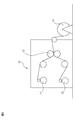
- FIG. 1A is a surface photograph of one surface (surface A) of the microporous film of the present disclosure
- FIG. 1B is a surface photograph of the other surface (surface B) of the same microporous film. It is a photograph which has a protrusion on the surface.
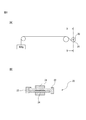
- FIG. 2 is a schematic view partially illustrating the production line of the microporous membrane of the present disclosure.
- FIG. 3 is a schematic view of a winder for peeling the microporous membrane product.
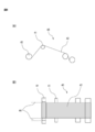
- FIG. 4 is a schematic view showing a method for evaluating the unwinding property of the winding core in the present specification.
- FIG. 5 is a schematic diagram showing a method for evaluating a deviation phenomenon in the present specification.
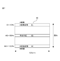
- FIG. 6 is a schematic view showing a method for evaluating transportability in the present specification.
- FIG. 7 is a schematic cross-sectional view of a microporous membrane for explaining a method for measuring an inclined structure in the present specification.
- the microporous membrane of the present disclosure (hereinafter sometimes referred to as "target layer") distinguishes one surface as “surface A” and the other surface opposite to surface A as “surface B".
- the material constituting the surface A may be substantially the same as or different from the material constituting the surface B.
- the microporous membrane can be used as a separator for a power storage element such as a separator for a lithium ion secondary battery.
- the microporous membrane may be a single layer.
- the single layer means that the microporous film is composed of a single-layer microporous film that does not use a laminating method or a coating method.
- the target layer (single-layer film) and the auxiliary layer are co-extruded into two or more layers, and the auxiliary layer is peeled off during the manufacturing process to form the target layer (single-layer film). You may get it.
- the microporous membrane may be a multilayer membrane such as a coextruded two-kind three-layer structure having the same surface layer. Also in the case of the multilayer film, it is preferable that the material constituting the surface A is substantially the same as the material constituting the surface B.
- the target layer (multilayer film) and the auxiliary layer may be coextruded and the auxiliary layer may be peeled off during the manufacturing process to obtain the target layer (multilayer film).
- the side in contact with the auxiliary layer is the surface B (the side having a high dynamic friction coefficient) of the target layer, and the other side is the surface A.
- the auxiliary layer has a role as a processing auxiliary layer from which a microporous film can be easily obtained.
- this auxiliary layer By the action of this auxiliary layer, it becomes easy to make the coefficient of dynamic friction on the surface B side in contact with the auxiliary layer higher than the coefficient of dynamic friction on the surface A side, and the total area of the holes on the surface B side in contact with the auxiliary layer can be summed up. It is also easy to make it smaller than the total area of the holes on the A surface side.
- the auxiliary layer is peeled off to obtain the target layer, a part of the peeled auxiliary layer may adhere to the surface B. In the case of "substantially the same", the presence of an auxiliary layer that may remain on the surface B is not considered.
- Microporous membrane the surface of the one surface A, when the surface A to the surface opposite to the surface B, the dynamic friction coefficient of the surface A and F A, the dynamic friction coefficient of the surface B was F B, F A is preferably 0.3 or less, more preferably 0.02 to 0.3, and even more preferably 0.1 to 0.3.
- F B is preferably 0.9 or less, more preferably 0.1 to 0.9, more preferably 0.5 or less, even more preferably from 0.1 to 0.5.
- the ratio of F B for F A (F B / F A ) is preferably in the range of 1.2 to 20. FIG. That is, of the surface A and the surface B, the one having the higher coefficient of dynamic friction is the surface B.
- F B / F A When F B / F A is 1.2 to 20 easily both extraction of the winding core when wound adhesion and cell coating layer.
- F B / F A is preferably in the range of 1.2-10. Deviation phenomena are the phenomenon which occurs in a state where the surface A and surface B in contact, it is particularly preferred both balance the reduction of misalignment phenomenon, i.e. F B / F A is within the above range.
- Microporous membrane is preferably in the range of F A is 0.02 ⁇ 0.3, F B is 0.1-0.9.
- F A is 0.02 or more, it is possible when contacting the core to the surface A when the battery of winding, to more reliably secure the microporous membrane against the winding core. Further, when it is 0.3 or less, the pullability of the winding core is improved.
- F A is preferably 0.05-0.25, more preferably in the range of 0.1-0.2.
- F B is 0.1 or more, offset phenomenon can be reduced, but also between separators when winding can wound not good too slippery.
- F B is 0.9 or less, slipperiness of the contact portion between the separator and winding machine is improved when the battery winding, transportability becomes favorable, thereby improving the productivity of the battery. In addition, the deviation phenomenon can be satisfactorily reduced.
- F B is preferably in the range within, more preferably of from 0.31 to 0.6 range from 0.1 to 0.7.
- Microporous membrane the surface of the one surface A, when the surface opposite to the surface B to the surface A, the number of pores of 1 [mu] m 2 on the surface A N A, pores of 1 [mu] m 2 on a surface B when the number and N B, N a is preferably 10 / ⁇ m 2 ⁇ 100 pieces / ⁇ m 2, N B is preferably 20 / ⁇ m 2 ⁇ 200 pieces / [mu] m 2.
- the ratio of N A for N B (N A / N B ) is preferably from 0.2 to 0.98. If N A is 10 pieces / [mu] m 2 or more, not too high coefficient of dynamic friction, coring can be suppressed defects, thereby improving the lithium ion permeability.
- N A is suppressed fine short as 100 or / [mu] m 2 or less, also improves film strength, Therefore film formation during handling is good, there is a tendency that thinning is facilitated.
- Range of N A is preferably 20 / ⁇ m 2 ⁇ 90 pieces / [mu] m 2, more preferably from 30 / ⁇ m 2 ⁇ 70 pieces / [mu] m 2.
- N B is 20 pieces / [mu] m 2 or more, not too low dynamic friction coefficient, offset phenomenon, and can suppress the wound defect, adhesion between the coating layer are improved, also, the lithium ion permeability It tends to improve.
- N B is 200 / [mu] m 2 or less if the dynamic friction coefficient is not too high and, fine short circuit is suppressed.
- Range of N B is preferably 30 / ⁇ m 2 ⁇ 150 cells / [mu] m 2, more preferably from 40 / ⁇ m 2 ⁇ 100 pieces / [mu] m 2.
- N A / N B permeability is good and is 0.2 or more, there is a tendency that the fine short circuit is suppressed to be 0.98 or less.
- N A / N B is more preferably 0.2 to 0.96 and more preferably greater than 0.2 to 0.90, even more preferably 0.3 to 0.90, particularly preferably 0.3 to It is in the range of 0.85, particularly preferably 0.5 to 0.8. If N A / N B is within this range, it is easy to adjust the friction coefficient of the A surface and B surface to a preferred scope of the present disclosure.
- a structure in which the physical properties of the microporous membrane, for example, the number of pores per unit area and the area of the pores change in the thickness direction of the microporous membrane is referred to as an "inclined structure" in the present specification.
- S A When S A is a 0.02 [mu] m 2 or more, the coefficient of dynamic friction is not too high, and tends to be improved lithium ion permeability. S A is suppressed fine short and is 0.5 [mu] m 2 or less, also improves film strength, Therefore film formation during handling is good, there is a tendency that thinning is facilitated. Range of S A is preferably 0.03 .mu.m 2 ⁇ 0.3 [mu] m 2, more preferably from 0.05 ⁇ m 2 ⁇ 0.2 ⁇ m 2. When S B is 0.01 [mu] m 2 or more, thereby improving the lithium ion permeability.
- Range of S B is preferably 0.02 [mu] m 2 ⁇ 0.2 [mu] m 2, more preferably from 0.03 ⁇ m 2 ⁇ 0.15 ⁇ m 2.
- S A / S B is within the range of 1.1-10, improvement of the core loss of the above, reduction of the offset phenomenon, transportability and easy to achieve both adhesion of the coating layer, ions Transparency is improved.
- S A / S B is preferably in the range of 1.5 to 5, more preferably in the range from 1.6 1-3.
- the present inventors have found that as long as it is within the range surface A, the area of the holes on the surface B (S A and S B) and number of pores (N A and N B) is in the above, F A, is F B preferred range I found that it was easy to obtain the separator inside.
- the surface A having a relatively large pore area has a low coefficient of dynamic friction, and when it is brought into contact with the winding core during the production of a wound lithium ion secondary battery, the winding core removal property is improved. ..
- the surface B having a small diameter and a large number of holes has a high coefficient of dynamic friction, the deviation phenomenon can be reduced.
- the adhesion to the electrodes is good, and particularly good adhesion to the electrodes is exhibited in a large square or pouch type battery. Further, in the coating type separator, when the coating layer is coated on the surface B, the adhesiveness of the coating layer is improved.
- Microporous membrane has a plurality of projecting bodies on the surface B, the number of the protruding member per 100 [mu] m 2 of surface B (W B) is in the range of 0.2 pieces / 100 [mu] m 2 ⁇ 1000 cells / 100 [mu] m 2 It is preferably inside. When W B is within this range, the dynamic frictional resistance F B surface B is liable to be within the preferred range.
- W B is more preferably in the range of 0.3 pieces / 100 [mu] m 2 ⁇ 100 pieces / 100 [mu] m 2, more preferably within the range of 0.3 pieces / 100 [mu] m 2 ⁇ 50 pieces / 100 [mu] m 2, further more It is preferably in the range of 0.5 pieces / 100 ⁇ m 2 to 15 pieces / 100 ⁇ m 2 .
- W B is the coefficient of dynamic friction becomes moderately large when is 0.2 pieces / 100 [mu] m 2 or more, offset phenomenon is reduced, thereby improving the adhesion strength of the coating layer and the microporous membrane. By W B is 1000/100 [mu] m 2 or less, the dynamic friction coefficient is adequately improved small becomes handling properties.
- the microporous membrane may have a plurality of protrusions on the surface A.
- the number of 100 [mu] m 2 per projecting member surface A (W A) is preferably less than 0.2 pieces / 100 [mu] m 2, is preferably more preferably from 0/100 [mu] m 2.
- Relationship between W A and W B are preferably W B> a 10 ⁇ W A, more preferably W B> 20 ⁇ W A. By W A is 0.2 ⁇ m or less, it is possible to lower the dynamic friction coefficient of the surface A.
- the size of the protrusions on the surface B is preferably 0.01 ⁇ m to 5 ⁇ m when the surface B is observed from the front.
- the method for measuring the size of the protruding body is described in Examples.
- the size of the protrusions on the surface B has a particularly preferable range for controlling the coefficient of friction of the surface B. That is, since the protruding body is 5 ⁇ m or less, the coefficient of kinetic friction can be easily suppressed to be low, and in the case of a coating type separator, the adhesive strength between the coating layer and the microporous film becomes good, and as a separator for a battery. When used, the microporous membrane is less likely to be clogged and ion permeability is improved.
- the size of the protruding body of the surface B is 0.01 ⁇ m or more, the coefficient of dynamic friction of the surface B is appropriately large, and the handleability is improved.
- the size of the protrusions on the surface B is more preferably 0.02 ⁇ m to 1 ⁇ m, further preferably 0.03 ⁇ m to 0.5 ⁇ m, and most preferably 0.1 ⁇ m to 0.5 ⁇ m.
- FIG. 1B shows an example of a protruding body on the surface B.
- the protrusion on the surface B is mainly composed of polyethylene or polypropylene. These resins are already widely used as raw materials for battery separators.
- "containing a specific component as a main component” means that the component is contained in a proportion exceeding 50% by mass based on the total mass of all the components.
- the method of forming the protrusions on the surface B includes, for example, a step of forming a microporous film having a surface A and a surface B opposite to the surface A; a fiber diameter of 1 ⁇ m on the surface B of the microporous film.
- Examples thereof include a method of attaching a protrusion containing a polyethylene or polypropylene having a diameter of about 10 ⁇ m as a main component. In this method, the above-mentioned fiber or a fragment obtained by cutting it into short pieces becomes a protrusion.
- the target layer and the target layer are co-extruded by coextrusion with the target layer having the surface A and the surface B on the opposite side of the surface A and the auxiliary layer.
- an extraction step of extracting the plasticizing agent from the microporous membrane raw fabric in the presence of an extraction solvent (c) peeling the auxiliary layer from the surface B of the target layer.
- Examples thereof include a manufacturing method including a peeling step of obtaining the target layer as a microporous film. In this method, for example, the fibril portion on the surface of the microporous membrane is pulled out from the protrusion, and a protrusion having a small size can be obtained. Any of these methods may be used. For more details, refer to the description in the column of "Method for producing microporous membrane".
- the ratio (%) of the number of pores having a pore diameter of 0.12 ⁇ m or more to the total number of pores observed near the surface of A in the cross section of the microporous membrane is NC A (0.12).
- the percentage (%) of the number of holes with a hole diameter of 0.12 ⁇ m or more is NC M (0.12), and among the total number of holes observed near the B surface.
- the number of holes having a hole diameter of 0.12 ⁇ m or more means that the surface A has many holes and the number of holes decreases toward the surface B. It is more preferable that the number of holes having a hole diameter of 0.12 ⁇ m or more decreases monotonically from the surface A to the surface B.
- NC A is preferably 2% to 5%, more preferably 2% to 3%.
- NC B is preferably 0.5% to 3.0%, more preferably 0.5% to 2.3%, 0.5 to 1.9%, 0.6% to 3. It is 0%, 0.6% to 2.3%, or 0.6% to 1.9%. Within these ranges, the dendrite suppression effect tends to be further improved.
- the ratio (%) of the number of pores with a pore diameter of less than 0.1 ⁇ m to the total number of pores observed near the surface of A in the cross section of the microporous membrane is NC A (0.10), cross section.
- the ratio (%) of the number of holes with a hole diameter of less than 0.10 ⁇ m is NC M (0.10), and among the total number of holes observed near the surface B,
- NC B (0.10)
- NC A (0.10) ⁇ NC M (0.10)
- ⁇ NC B (0.10) is preferable.
- the number of holes having a hole diameter of less than 0.1 ⁇ m means that the number of holes increases from the A surface toward the B surface. It is more preferable that the number of holes having a hole diameter of less than 0.1 ⁇ m decreases monotonically from the A surface to the B surface. Within this range, the dendrite suppression effect tends to be further improved.
- the microporous membrane is NC A (0.12)> NC M (0.12)> NC B (0.12) and NC A (0.10) ⁇ NC M (0.10) ⁇ NC.
- B (0.10) is more preferable. That is, the number of holes having a relatively large diameter of 0.12 ⁇ m or more is large on the A surface and decreases toward the surface B, and the number of holes having a relatively small diameter of less than 0.1 ⁇ m is on the A surface. It means that it increases from B to the B surface. As a result, the dendrite suppressing effect tends to be further improved.
- ⁇ A> ⁇ B it means that the pore diameter increases from the B surface toward the A surface as the number of holes having a small diameter decreases from the B surface toward the A surface in the thickness direction.
- a film having such a pore structure for example, when dendrites grow from the A surface toward the B surface inside the film, the pore diameter becomes smaller in the middle, so that straightness is impaired and it is difficult to penetrate the separator. Become. On the contrary, when it grows from the B surface, it becomes difficult to penetrate the inside of the separator from the B surface.
- the average pore size of the B surface of the pores (diameter) and [Phi B, [Phi B is adjusted as small as possible, It is preferably in the range of 5 nm to 100 nm, more preferably 10 nm to 80 nm, and even more preferably 20 nm to 70 nm.
- the number of pores, the pore area and the pore diameter are closely related to each other. For example, if the number of pores having a small diameter increases from the A surface to the B surface, the average pore area basically becomes. It is preferable to have an inclined structure in which the number of holes is reduced and the average pore size is also reduced.
- the microporous membrane obtained by the wet method and / or the dry method is used as a separator for a lithium ion battery.
- a separator application there is a problem that a slight short circuit is likely to occur when the battery is repeatedly charged and discharged.
- One of the causes is that dendritic metallic lithium (lithium dendrite) is deposited on the surface of the negative electrode, and when charging and discharging are repeated, the lithium dendrite grows toward the positive electrode, breaks through the separator, and is partially inside. The phenomenon that causes a short circuit is mentioned.
- Patent Document 8 describes a separator having a porous structure of two or more layers, one of which is a layer that does not react with dendrites.
- Patent Document 7 describes a separator having a multi-layer structure of two or more layers, one layer having a small pore diameter and the other layer having a large pore diameter.
- Patent Document 6 does not describe dendrite, but describes a separator for a lithium ion secondary battery having a two-layer structure, which is made of a wet method, and the pore diameters of the two layers are different and the ratio is specific. It describes a separator.
- none of the techniques described in Patent Documents 6 to 8 could sufficiently achieve improvement in transparency and prevention of dendrites.
- the separators or microporous membranes described in these documents all have a two-layer multi-layer structure, and have a problem of peeling at the interface.
- the thickness cannot be reduced, and in the case of multi-layer coextrusion, there is a problem that the film breaks during co-stretching because each layer is different, and high-magnification stretching cannot be performed. It was difficult to increase the strength.
- Patent Document 9 describes a polyethylene microporous membrane made of a polyethylene-based resin, which is adjacent in the thickness direction and has a dense structure region having an average pore diameter of 0.01 ⁇ m to 0.05 ⁇ m and a dense structure having an average pore diameter of 0.01 ⁇ m to 0.05 ⁇ m. Described is a polyethylene microporous membrane which is a single membrane having a coarse structural region 1.2 times to 5.0 times the region, and is characterized in that the coarse structural region is formed on at least one surface.
- a melt-kneaded product with a film-forming solvent is extruded from a die, and an extruded molded product obtained through an extruder and a die is cooled by a single-sided cast roll so that a temperature distribution is generated in the film thickness direction. It is described that it is obtained by a method of forming a gel-like sheet.
- Patent Document 9 describes that a film having a pore size distribution in the thickness direction can be obtained in this way.
- the thickness of the separator is 18 ⁇ m or less, most of which is 10 ⁇ m or less, and a thin film of about 6 ⁇ m is the mainstream.
- the microporous membrane contains 1 to 15% by mass of a high molecular weight component having a molecular weight of 1,000,000 or more, and if it exceeds that, a coarse structure cannot be formed. ..
- a separator such as polyolefin (hereinafter, may be referred to as "coating base material” or the like) has an inorganic filler coating layer such as alumina or silica or an organic coating layer such as latex or aramid resin. Separator is also increasing mainly for in-vehicle use. This coating layer is intended to prevent heat shrinkage and film rupture at high temperatures due to the inorganic filler layer, or to improve battery performance by improving adhesion to electrodes by the organic coating layer. It is widespread. Further, in in-vehicle applications, thinning of the separator is required due to the demand for miniaturization of the battery itself.
- the coating substrate is required to be thinner, but the separators described in Patent Documents 6 to 9 are thinner. And the improvement of battery performance such as prevention of electrode deterioration could not be satisfied.
- the microporous film has an inclined structure, it is possible to obtain a microporous film that satisfies both thinning and improvement of battery performance such as prevention of electrode deterioration.
- the reason is not limited to theory, but is considered as follows. That is, lithium dendrite grows as charging and discharging are repeated. Lithium dendrite and the like grow from the negative electrode side during charging and discharging, and are taken into the inside from the separator surface.
- the holes are arranged in the growth direction of the lithium dendrite. It is considered that the growth rate of lithium dendrite can be reduced by reducing the area and increasing the number of small-diameter holes. Therefore, a microporous film in which the pore structure gradually changes in the thickness direction is different from a microporous film in which only the pore structure on the surface is different, or a microporous film in which the pore structure changes rapidly, and impurities and lithium dendrites are used. Is excellent in the effect of preventing the film from penetrating the separator, and tends to have a high electrode deterioration preventive property. This effect is also related to the hole area and the number of holes on both surfaces.
- the thickness of the microporous membrane is preferably in the range of 3 ⁇ m to 18 ⁇ m.
- the thickness is 3 ⁇ m or more, the mechanical strength is increased and troubles such as tearing can be suppressed in the production process.
- the thickness is 18 ⁇ m or less, the battery provided with the microporous membrane can be thinned.
- the thickness of the microporous membrane is more preferably 3 ⁇ m to 12 ⁇ m, further preferably 3 ⁇ m to 10 ⁇ m, and even more preferably 3 ⁇ m to 8 ⁇ m.
- the piercing strength converted to the thickness of the microporous membrane of 10 ⁇ m is 300 gf / 10 ⁇ m or more.
- the puncture strength is preferably 350 gf / 10 ⁇ m or more, more preferably 400 gf / 10 ⁇ m or more, further preferably 500 gf / 10 ⁇ m or more, and the upper limit is preferably 1200 gf / 10 ⁇ m or less.
- the puncture strength is 1200 gf / 10 ⁇ m or less, overstretching can be prevented and the dimensional stability of the target layer can be improved.
- the puncture strength of the microporous membrane can be controlled within the above numerical range.
- the porosity of the microporous membrane is preferably 20% to 75%.
- the upper limit of the porosity is arbitrarily set from the viewpoint of suppressing a decrease in mechanical strength and deterioration of heat shrinkage, and the lower limit thereof is arbitrarily set from the viewpoint of lithium ion permeability, that is, battery performance, and a slight short circuit. It is set arbitrarily from the viewpoint of suppressing.
- the porosity of the microporous membrane is preferably 30% to 60%, more preferably 35% to 55%.
- the air permeability converted to the thickness of the microporous membrane of 10 ⁇ m is 30 sec / 100 ml / 10 ⁇ m to 1000 sec / 100 ml / 10 ⁇ m. Converting the air permeability to "converting the thickness of the microporous membrane to 10 ⁇ m" is the same as the above-mentioned calculation of the puncture strength converted to the thickness of 10 ⁇ m.
- the lower limit of air permeability is defined from the viewpoint of suppressing a decrease in mechanical strength and deterioration of heat shrinkage, and the upper limit is defined by lithium ion permeability, that is, battery performance, and also suppresses a slight short circuit.
- the air permeability in terms of the thickness of the microporous membrane of 10 ⁇ m is more preferably 50 sec / 100 ml / 10 ⁇ m to 500 sec / 100 ml / 10 ⁇ m, and even more preferably 90 sec / 100 ml / 10 ⁇ m to 400 sec / 100 ml / 10 ⁇ m.
- the surface A and surface B of the microporous membrane preferably contain polyethylene as a main component.
- polyethylene high-density polyethylene, linear low-density polyethylene, low-density polyethylene and the like are used. High-density polyethylene having a high molecular weight and a high density is preferable from the viewpoint of strength.
- Polyethylene preferably contains 5% by mass to 30% by mass of components having a viscosity average molecular weight of 2,000,000 or more.
- the polyethylene is preferably an ultra-high molecular weight polyethylene having a viscosity average molecular weight of 500,000 to 900,000.
- the polyethylene contains ultra-high molecular weight polyethylene, preferably 10% by mass or more, preferably 10% by mass to 97% by mass, and more preferably 20% by mass to 95% by mass, based on the total mass of polyethylene. Further, other polymers such as polypropylene and propylene-based elastomer may be contained as long as the characteristics of the separator are not impaired. It is also preferable that the surface A and the surface B of the microporous membrane contain 20% by mass or more of an ultrahigh molecular weight component having a viscosity average molecular weight of 1,000,000 or more based on the mass of all the polymers forming the microporous membrane. .. As a whole, polyethylene preferably has a viscosity average molecular weight of 200,000 or more.
- the microporous film may further have a coating layer containing an inorganic filler or an organic paint from the viewpoint of further improving the shrinkage characteristics.
- the coating layer is preferably an inorganic filler layer containing an inorganic filler.
- the microporous film may have a coating layer on either the surface A or the surface B, but the coating layer is provided on the surface B having a higher dynamic friction resistance and a relatively small pore area than the surface A. It is preferable to have it from the viewpoint of the adhesive strength of the coating layer and the prevention of clogging of the holes by the paint.
- the coating material for forming the inorganic filler layer containing the inorganic filler can be, for example, a mixed solution containing 1 part by mass to 30 parts by mass of the binder and, if necessary, a solvent with respect to 100 parts by mass of the inorganic filler. ..
- the inorganic filler the same one as the component contained in the auxiliary layer described later can be used.
- the binder include polyolefins such as polyethylene and polypropylene; fluororesins such as polyvinylidene fluoride and polytetrafluoroethylene; vinylidene fluoride-hexafluoropropylene-tetrafluoroethylene copolymers and ethylene-tetrafluoroethylene.
- Fluorine-containing rubber such as copolymer; styrene-butadiene copolymer and its hydride, acrylonitrile-butadiene copolymer and its hydride, acrylonitrile-butadiene-styrene copolymer and its hydride, methacrylic acid ester-acrylic acid Rubbers such as ester copolymers, styrene-acrylic acid ester copolymers, acrylonitrile-acrylic acid ester copolymers, ethylene propylene rubber, polyvinyl alcohol, and vinyl acetate; polyphenylene ether, polysulfone, polyether sulfone, polyphenylene sulfide , Polyetherimide, polyamideimide, polyamide, and resins having a melting point and / or glass transition temperature of 180 ° C. or higher such as polyester can be mentioned.
- ⁇ Manufacturing method of microporous membrane As one of the methods for producing the microporous film of the present disclosure, there is a method of attaching a protrusion to the surface B of the microporous film.
- a protrusion containing polyethylene or polypropylene having a fiber diameter of 1 ⁇ m to 10 ⁇ m as a main component may be attached to the surface B of the microporous film produced by the wet method.
- the ratio of the dynamic friction coefficient of the surface B to the dynamic friction coefficient of the surface A (F A) (F B ) to (F B / F A) 1.2 ⁇ It is easy to keep it within the range of 20.
- the fiber diameter may be measured on an SEM photograph.
- a method for producing a microporous film for example, a non-woven fiber having a diameter of about 1 ⁇ m to 3 ⁇ m obtained by cutting and crushing a non-woven fabric made by an arbitrary method such as a melt blow method or a spunbond method is prepared in advance.
- the predetermined amount, non-woven fiber number of the protruding body formed by (W B) is, for example, an amount to be 0.2 units / 100 [mu] m 2 ⁇ 1000 cells / 100 [mu] m 2. More specifically, when a non-woven fiber made of isotactic polypropylene and having a diameter of about 2 ⁇ m is attached to a microporous film of high-density polyethylene, the heat-bonding temperature is preferably 100 ° C. It is in the range of about 150 ° C., more preferably 120 ° C. to 135 ° C.
- the temperature of thermal bonding is affected by the bonding pressure and bonding time, but if you are a person skilled in the art, the pore structure of the microporous film is deformed by heat, and the microporous is blocked and permeated by the bonded non-woven fabric or the like. Considering that the property may be deteriorated, conditions within a range in which the original purpose as a separator can be achieved, that is, temperature, pressure, and the like can be selected.
- a target layer which becomes a microporous film
- an auxiliary layer that can be peeled off from the target layer
- a microporous film raw fabric in which the target layer and the auxiliary layer are laminated is obtained.
- a stretching step of stretching the microporous membrane raw fabric is obtained, after the coextrusion step, a stretching step of stretching the microporous membrane raw fabric, an extraction step of extracting and removing a plasticizer from the microporous membrane raw fabric, and a peeling step of peeling the peeling layer from the target layer.
- a method may be mentioned in which the steps are included in any order.
- a method for producing a microporous film which includes the following: a target layer having a surface A and a surface B on the opposite side and containing a plasticizer, and an auxiliary layer containing a plasticizer. It includes a coextrusion step of forming a microporous membrane raw fabric containing an auxiliary layer on the target layer and the surface B of the target layer by extrusion.
- the method is as follows: (a) to (c): (a) a stretching step of stretching the microporous membrane raw fabric after the coextrusion step; (b) from the microporous membrane raw fabric in the presence of an extraction solvent.
- An extraction step of extracting the plasticizer; (c) a peeling step of peeling the auxiliary layer from the surface B of the target layer to obtain the target layer as a microporous film may be included in any order.
- the target layer preferably contains 40% by mass or more of a plasticizer based on the total mass of the target layer.
- the auxiliary layer preferably contains 60% by mass or less of a plasticizer based on the total mass of the auxiliary layer.
- the method may further include the step of re-stretching the microporous membrane raw fabric at a predetermined temperature.
- the target layer is a layer that becomes the microporous film of the present disclosure, and the auxiliary layer is a layer used for film formation and is a layer that is removed from the target layer in the peeling step.
- the target layer may be a single layer.
- the present inventors have found that by using the manufacturing method of the microporous film, it is easy to generate is projecting member on the surface B form, the ratio of the dynamic friction coefficient of the surface B to the dynamic friction coefficient of the surface A (F A) (F B ) the (F B / F a), was found to be easy to within the range from 1.2 to 20.
- FIG. The reason is that the fibrils on the surface of the microporous film layer that have already been generated are pulled in the peeling direction in a state of being partially fused to the auxiliary layer by the peeling step, so that the fibrils of the microporous layer and / and the auxiliary layer are on the surface B. It is considered that this is because is fixed in the pulled out state and forms a protruding body.
- the number W B of the protruding body surface B because the stripping step is greatly affected by the degree or the like of the fusion of the re-stretching step prior to flaking, to consider the melting point of the resin to a temperature in the above-described re-stretching step is important.
- the re-stretching temperature is preferably 110 ° C. to 140 ° C. It is within the range, more preferably in the range of 120 ° C. to 135 ° C.
- the peeling step, stretching step, and extraction step may be performed in any order as long as they are performed after the extrusion step.
- the method for producing a microporous film preferably includes (a) a stretching step, (b) an extraction step, and (c) a peeling step in this order after the extrusion step.
- the method for producing a microporous film further includes a re-stretching step, more preferably, after the extrusion step, (a) stretching step, (b) extraction step, re-stretching step, and (c) peeling step are performed in this order. include.
- the microporous membrane raw fabric obtained by the coextrusion step is also called a precursor of a microporous membrane product, a coextruded raw fabric, a pre-stretched raw fabric, a co-stretched raw fabric, a precursor sheet, or a resin raw fabric.
- the layer structure of the microporous membrane raw fabric at the time of coextrusion may be two or more layers including the target layer.
- the microporous membrane raw fabric has a three-layer structure, it has a three-layer structure of a target layer / an auxiliary layer / a target layer, the auxiliary layer side of the two target layers corresponds to the surface B, and the other is the surface A.
- the productivity per film forming facility becomes extremely high.
- the target layer and auxiliary layer used in the method for producing a microporous membrane, and each step will be further described below.
- ⁇ Target layer> As the raw material of the target layer, it is preferable to use polyolefin as a main component from the viewpoint of molding processability, solvent resistance to the electrolytic solution, and low temperature shutdown property.
- the low-temperature shutdown property is a safety function that blocks the current by closing the holes of the separator when it is overheated near the melting point of the resin even during the thermal runaway of the battery, and is activated near the melting point temperature of the raw material resin.
- the polyolefin include polyethylene and polypropylene.
- polyethylene examples include high-density polyethylene, ultra-high molecular weight polyethylene, linear low-density polyethylene, high-pressure low-density polyethylene, and mixtures thereof.
- a microporous membrane is used as a separator, linear high-density polyethylene by ionic polymerization, ultra-high molecular weight polyethylene, or a mixture thereof is preferable from the viewpoint of reducing heat shrinkage.
- the ultra-high molecular weight polyethylene refers to polyethylene having a viscosity average molecular weight of 500,000 or more.
- the ratio of ultra-high molecular weight polyethylene to the total polyethylene is preferably 5% by mass to 97% by mass, more preferably 10% by mass to 97% by mass, and further preferably 20% by mass to 95% by mass from the viewpoint of dispersibility. %.
- the viscosity average molecular weight (Mv) of polyethylene is preferably 200,000 or more, more preferably 300,000 or more, still more preferably 500,000 or more, from the viewpoint of improving the strength of the microporous membrane.
- the viscosity average molecular weight (Mv) means the total viscosity average molecular weight of a plurality of types of polyethylene when they are used.
- the molecular weight distribution (Mw / Mn) of polyethylene is from the viewpoint of improving the kneading property when inorganic particles and the like are mixed and kneaded, and suppressing the occurrence of granular defects in which the inorganic particles are secondarily agglutinated. It is preferably 6 or more, and more preferably 8 or more.
- polypropylene examples include homopolymers of propylene such as isotactic polypropylene, syndiotactic polypropylene, and tactic polypropylene; and copolymerization of propylene with comonomers such as ethylene or butene and ⁇ -olefin having 5 or more carbon atoms. Examples thereof include a random copolymer, a block copolymer, and a tarpolymer obtained by subjecting the mixture. Further, polypropylene having reduced stereoregularity may be blended with the raw material resin of the target layer in a small amount, preferably 10% by mass or less by using a metallocene catalyst or the like. Among the above, isotactic polypropylene is preferable from the viewpoint of balance between moldability and physical properties such as strength and rigidity.
- the viscosity average molecular weight (Mv) of polypropylene is preferably 1,200,000 or less, more preferably 900, from the viewpoint of facilitating melt-kneading and improving fish-eye-like defects when formed into a microporous film. It is 000 or less, more preferably 800,000 or less.
- the raw material resin for the target layer is polyethylene, which generally has a lower melting point than polypropylene. It is preferably contained as a main component.
- the formed microporous membrane can contain polyethylene as a main component.
- the content of polyethylene in the microporous membrane is preferably 60% by mass or more, more preferably 85% by mass or more, and further, based on the total mass of the non-volatile components of the microporous membrane, from the viewpoint of extrusion moldability and shutdown temperature. It is preferably 92% by mass or more.
- the polyethylene in the microporous film has a viscosity average molecular weight of more than 500,000 to 900,000 based on the total mass of the polyethylene.
- High molecular weight polyethylene is preferably contained in an amount of 10% by mass or more, more preferably 10% by mass to 97% by mass, still more preferably 20% by mass to 90% by mass or 20% by mass to 80% by mass or 20% by mass to 70% by mass. do.
- the microporous film contains an ultra-high molecular weight component having a viscosity average molecular weight of 1,000,000 or more, for example, an ultra-high molecular weight polyethylene having a viscosity average molecular weight of 1,000,000 or more, and a total of non-volatile components of the microporous film. Based on the mass, it preferably contains 20% by mass or more, more preferably 20% by mass to 80% by mass, and further preferably 30% by mass to 70% by mass.
- the method for producing a microporous membrane may include a step of providing at least one auxiliary layer adjacent to the microporous membrane (target layer) described above.
- the auxiliary layer by taking the appropriate composition, in the manufacturing process of the microporous membrane, the surface A of the object layer, and each of 1 [mu] m 2 (1 square micron) per hole number N A of the surface B, and N B , N a, N B, and N a / N B may serve to control the optimal range.
- S A, S B, NC A , NC B is the same even on controlling the NC M.
- the auxiliary layer can play the role of a stretching auxiliary layer when the coextruded microporous membrane raw fabric is stretched. That is, even if the target layer is as thin as about 3 ⁇ m to 6 ⁇ m, which is difficult to achieve when only the target layer is stretched, such a thin target layer can be easily produced by the method using the auxiliary layer. For example, when producing a target layer having a thickness of 4 ⁇ m, if the thickness of the auxiliary layer is adjusted to 4 ⁇ m and a three-layer coextruded raw fabric of the target layer / auxiliary layer / target layer is used, the total thickness of all layers is 12 ⁇ m. , High magnification stretching is easy. Further, if a composition capable of stretching at a temperature lower than the optimum stretching temperature of the target layer is selected as the composition of the auxiliary layer, the target layer can be highly oriented and the strength of the target layer can be increased.
- the raw material of the auxiliary layer should be selected in consideration of not only coextrusion and co-stretchability but also releasability from the target layer, the microporous membrane.
- the raw material of the auxiliary layer for example, polyolefins such as polyethylene and polypropylene; and polyamide, polyester, polyvinylidene fluoride and the like are preferably used.
- the peel strength with the microporous membrane or the strength at the time of peeling can be used as an index for selecting the raw material of the auxiliary layer. For example, when high-density polyethylene having a melting point of 135 ° C.
- a resin having a melting point higher than that of polyethylene such as polypropylene or polyethylene terephthalate (PET) is used as a raw material for the auxiliary layer.
- PET polyethylene terephthalate
- polypropylene is used as the raw material resin for the auxiliary layer, coextrusion and co-stretchability with a microporous film containing polyethylene as a main component are improved, so that a microporous film having an excellent film thickness distribution can be obtained.
- a random copolymer or polypropylene having low stereoregularity is used as the raw material resin for the auxiliary layer, the stretchability is further improved, so that not only the film thickness distribution is improved but also the film thickness distribution is improved. The balance between permeability and strength of the obtained microporous membrane is also improved.
- the stretching aid for example, two or three kinds of random copolymerized elastomers of polybutene-1, petroleum resin, ethylene, propylene and 1-butene comonomer, styrene-butadiene rubber and the like are used as the resin raw material of the auxiliary layer. When mixed, the strength of the auxiliary layer itself is improved, and the auxiliary layer can be thinned.
- the stretching aid examples include elastomers having a melting point of 130 ° C. or higher, preferably 140 ° C. or higher, and most preferably 150 ° C. or higher in order to prevent heat fusion between the target layer and the auxiliary layer in the heat treatment step.
- the raw material resin for the auxiliary layer examples include homopolypropylene having a melting point of 160 ° C. or higher. In this case, the stretchability is improved by appropriately mixing the stretching aid with the raw material resin.
- the auxiliary layer preferably contains an inorganic filler in order to improve the peelability.
- the inorganic filler include oxide-based ceramics such as alumina (for example, ⁇ -alumina), silica, titania, zirconia, magnesia, ceria, itria, zinc oxide, and iron oxide; silicon nitride, titanium nitride, and nitrided.
- oxide-based ceramics such as alumina (for example, ⁇ -alumina), silica, titania, zirconia, magnesia, ceria, itria, zinc oxide, and iron oxide
- silicon nitride, titanium nitride, and nitrided Nitride ceramics such as boron; silicon carbide, calcium carbonate, aluminum sulfate, aluminum hydroxide, potassium titanate, talc, kaolin clay, kaolinite, halloysite, pyrophyllite, montmorillonite, sericite
- Asbestos, zeolite, calcium silicate, magnesium silicate, kaolin, and ceramics such as kaolin; and glass fibers, etc. which may be used alone or in combination of two or more. good.
- silica, alumina, calcium carbonate, talc, zinc oxide and the like are particularly preferable.
- the particle size of the inorganic filler is preferably in the range of 0.05 ⁇ m to 10 ⁇ m. When the particle size of the inorganic filler is within this range, the inorganic filler reinforces the resin film and improves the strength of the auxiliary layer itself, so that the auxiliary layer is not easily torn during the peeling process, and stable production can be performed. can.
- the particle size of the inorganic filler is more preferably in the range of 0.05 ⁇ m to 8 ⁇ m, still more preferably 0.1 ⁇ m to 8 ⁇ m, and even more preferably in the range of 0.1 ⁇ m to 5 ⁇ m. Within this range, the strength of the auxiliary layer is increased, the peeling speed is increased, and the productivity can be improved.
- the content of the inorganic filler is preferably 5 parts by mass to 300 parts by mass when the resin component contained in the auxiliary layer is 100 parts by mass because the peelability tends to be improved.
- the content of the inorganic filler is more preferably 5 parts by mass to 100 parts by mass based on 100 parts by mass of the resin component of the auxiliary layer, and if it is within this numerical range, the strength of the auxiliary layer itself is increased and peeling is performed. At that time, the auxiliary layer is not torn and can be peeled off at high speed.
- the content of the inorganic filler is more preferably 8 parts by mass to 50 parts by mass based on 100 parts by mass of the resin component of the auxiliary layer, and if it is within this numerical range, the peeling speed can be further increased.
- the peeling strength of the auxiliary layer adjacent to the microporous membrane which is the target layer is at a speed of 100 mm / min.
- the peeling speed is preferably 250 gf / 25 mm width or less.
- at least one auxiliary layer separated from the microporous membrane of the target layer is preferably a microporous membrane or a non-porous membrane having an air permeability of 3000 sec / 100 ml or more.
- non-porous membrane refers to a membrane having an air permeability of more than approximately 10,000 sec / 100 ml in the present specification.
- the present inventors have found that, when the air permeability of the auxiliary layer is 3000 sec / 100 ml or more, preferably satisfies the condition of dynamic friction coefficient of the surface A and surface B F A and F B, and / or preferably inclined structure with the intended layer I found that it was easy to form.
- the reason for this phenomenon is not bound by theory, but the inventors speculate as follows. That is, in order to set the air permeability of the auxiliary layer relatively high while setting the air permeability of the target layer low, the amount of the plasticizer mixed in the target layer during coextrusion is set to the total mass of the target layer.
- the amount of the plasticizer mixed in the auxiliary layer is 60% by mass or less based on the total mass of the auxiliary layer, and preferably the amount of the plasticizer mixed in the target layer is mixed in the auxiliary layer. More than the amount of agent.
- the number of large pores decreases from the A surface to the B surface
- the number of small pores increases from the A surface to the B surface
- the pore area and average pore diameter increase from the A surface to the B surface. It is speculated that an inclined structure that decreases toward is obtained. This phenomenon can be adjusted by the extrusion conditions such as the amount of plasticizer, temperature and pressure, and the structure of the die. Further, the composition of the auxiliary layer in the production method implemented in the present application can also be adjusted.
- the auxiliary layer preferably has a piercing strength of 40 gf or more.
- the puncture strength of the auxiliary layer is more preferably 80 gf or more from the viewpoint of peelability of a film having a relatively wide width, and more preferably 120 gf or more from the viewpoint of high-speed peelability.
- the puncture strength of the auxiliary layer is most preferably 200 gf or more, and when it is 200 gf or more, peeling and productivity are further stabilized.
- the target layer and the auxiliary layer contain a plasticizer.
- the plasticizer include liquid paraffin, DBP: dibutyl isophthalate, DOP: dioctyl isophthalate, DIDP: diisodecyl isophthalate, DTDP: ditetradecyl isophthalate and the like.
- the target layer contains 40% by mass or more of the plasticizer, and the auxiliary layer contains 60% by mass or less of the plasticizer.
- the content of the plasticizer in the microporous membrane layer is related to the permeation performance of the microporous membrane, and in the case of a separator for a lithium ion secondary battery, the output or cycle performance of the battery. It is mass% or more, preferably 50 mass% or more, and more preferably 60 mass% or more.
- the content of the plasticizer in the target layer is preferably set in order to increase the film strength, prevent the permeability from becoming excessively large in the case of a separator for a lithium ion secondary battery, and suppress a slight short circuit or the like. It is 90% by mass or less.
- the content of the plasticizer in the target layer is preferably higher than the content of the plasticizer in the auxiliary layer.
- the content of the plasticizer in the auxiliary layer during the extrusion step is 60% by mass or less, preferably 40% by mass or less, more preferably 30% by mass or less, and further preferably 20% by mass or less. If the amount of the plasticizer in the auxiliary layer is more than 60% by mass, it is difficult to obtain the inclined structure according to the present embodiment, the strength of the auxiliary layer film is weakened, and the film is easily broken during the peeling step.
- the content of the plasticizer in the auxiliary layer is preferably more than 0% by mass, for example, 0.1% by mass or more, 0.5% by mass or more, 1% by mass or more, 3% by mass or more, or 5% by mass. It can be more than that.
- the target layer and the auxiliary layer may contain an antioxidant.
- the antioxidant include phenolic antioxidants such as "Irganox 1010", “Irganox 1076", and “BHT” (all of which are trademarks manufactured by Ciba Speciality Chemicals); phosphorus-based or sulfur-based antioxidants. Secondary antioxidants; and hindered amine-based weathering agents and the like can be mentioned.
- the antioxidants can be used alone or in combination of two or more.
- the antioxidant is preferably a combination of a phenolic antioxidant and a phosphorus-based antioxidant. Specifically, pentaerythrityl-tetrakis [3- (3,5-di-t-butyl-4-hydroxyphenyl) propionate], octadecyl-3- (3,5-di-t-butylhydroxyphenyl) propionate.
- phenolic antioxidants selected from 1,3,5-trimethyl-2,4,6-tris (3,5-di-t-butylhydroxybenzyl) benzene and the like, and tris (3,5-di-t-butylhydroxybenzyl).
- the amount of the antioxidant added can be adjusted according to the application of the microporous membrane, and is generally in the range of 100 PPM to 1% by mass based on the mass of each layer.
- the mass ratio of the phenol-based / phosphorus-based antioxidant is preferably 1/3 to 3/1.
- the target layer and the auxiliary layer may contain additives for modifying the layer.
- the additive include antifogging materials such as glycerin ester; slip materials typified by fatty acid amides such as erucic acid, stearic acid and oleic acid; antistatic agents; inorganic fillers such as silica and alumina; liquid paraffin and the like.
- antifogging materials such as glycerin ester
- slip materials typified by fatty acid amides such as erucic acid, stearic acid and oleic acid
- antistatic agents such as silica and alumina
- inorganic fillers such as silica and alumina
- liquid paraffin and the like examples thereof include lubricating oils such as calcium stearate or internal lubricants; peeling aids such as silicone-based solid release agents.
- the antistatic agent examples include amines such as alkyldiethanolamine and hydroxyalkylethanolamine; amine esters such as stearyldiethanolamine monofatty acid ester; alkyloamides such as laurate diethanolamide and stearate diethanolamide; glycerin, diglycerin and the like. Mono fatty acid esters; anionic antistatic agents such as alkylbenzene sulfonic acid; polyoxyethylene alkyl ethers and the like.
- the antistatic agent may be used alone or in combination of two or more.
- the blending amount of the antistatic agent is preferably 500 ppm to 10,000 ppm with respect to the total resin solid content forming each layer.
- the inorganic filler examples include oxide-based ceramics such as alumina (for example, ⁇ -alumina), silica, titania, zirconia, magnesia, ceria, itria, zinc oxide, iron oxide; silicon nitride, titanium nitride, boron nitride and the like.
- oxide-based ceramics such as alumina (for example, ⁇ -alumina), silica, titania, zirconia, magnesia, ceria, itria, zinc oxide, iron oxide; silicon nitride, titanium nitride, boron nitride and the like.
- Nitride ceramics silicon carbide, calcium carbonate, aluminum sulfate, aluminum hydroxide, potassium titanate, talc, kaolin clay, kaolinite, halloysite, pyrophyllite, montmorillonite, cericite, mica, amesite, bentonite, asbestos , Ceramics such as zeolite, calcium silicate, magnesium silicate, kaolin, kaolin; glass fiber and the like; these may be used alone or in combination of two or more.
- the blending amount of the inorganic filler is preferably 1% by mass to 50% by mass, preferably 5% by mass to 30% by mass, based on the total resin solid content forming each layer. For more details on the inorganic filler that can be contained in the auxiliary layer, refer to the above “ ⁇ Auxiliary layer>” column.
- the internal lubricant examples include calcium stearate, magnesium stearate or hydrates thereof, for example, sodium 12-hydroxystearate and the like.
- the preferable content of the internal lubricant is in the range of 50 ppm to 5000 ppm based on the total resin solid content forming each layer.
- ⁇ Method of obtaining two target layers from a coextruded raw fabric having a three-layer structure of target layer / auxiliary layer / target layer An example of a method of obtaining two target layers from a coextruded raw fabric having a three-layer structure of a target layer / auxiliary layer / target layer including two microporous membranes as the target layer and one auxiliary layer will be described. do.
- the following examples include a case where the target layer is a single layer containing polyethylene (PE) as a main component and the auxiliary layer contains polypropylene (PP) as a main component.
- PE polyethylene
- PP polypropylene
- the target layer is a multilayer film
- a resin other than polyethylene (PE) is contained as a main component
- the auxiliary layer contains a resin other than polypropylene as a main component
- 2 It is possible to obtain one target layer at a time.
- two extruders are required because of coextrusion, but it is very economical because two target layers can be obtained by one extrusion.
- only one casting device, stretching device, etc., downstream of the extruder is required, so that the equipment cost is significantly improved.
- One extruder extrudes a raw material composition containing a predetermined amount of a polyethylene raw material and a plasticizer as a target layer, and another extruder uses a resin raw material and a plasticizer containing polypropylene as an auxiliary layer as a main component. Is compounded in a predetermined amount or extruded without compounding.
- a co-extruded die so as to have a three-layer structure of, for example, a target layer / an auxiliary layer / a target layer, and cast molding is performed to obtain a microporous membrane raw fabric (precursor of a microporous membrane product) before stretching. ..
- the raw material resin and, in some cases, a plasticizer are pre-kneaded with a Henschel mixer or a tumbler mixer, and the obtained kneaded product is put into an extruder and the extruder is used.
- a method of introducing a plasticizer in an arbitrary ratio to a predetermined amount while heating and melting the plasticizer, and further kneading the plasticizer is preferable from the viewpoint that a sheet having a good dispersibility of the resin composition can be obtained, and each of the target layer and the auxiliary layer can be stretched without breaking the film even at a high magnification.
- the melt extruder for example, a twin-screw extruder can be used.
- the L / D of the screw of the twin-screw extruder is preferably about 20 to 70, and more preferably 30 to 60.
- L represents the screw length
- D represents the screw diameter.
- a screw having a full flight portion and a kneading portion such as a kneading disc or a rotor can be generally used.
- a single-screw extruder can also be used.
- the content of the plasticizer in the microporous membrane layer is related to the permeation performance of the microporous membrane and, in the case of a separator for a lithium ion secondary battery, the output or cycle performance of the battery. It is preferably 40% by mass or more, more preferably 50% by mass or more, and further preferably 60% by mass or more. However, if the amount of the plasticizer is too large, there will be a problem of film strength, or in the case of a separator for a lithium ion secondary battery, the permeability will be excessively large, and problems such as a slight short circuit will occur.
- the content of the plasticizer is preferably 90% by mass or less.
- the content of the plasticizer in the auxiliary layer during the extrusion step is preferably 60% by mass or less, more preferably 40% by mass or less, still more preferably 30% by mass or less, still more preferably 20% by mass or less. If the amount of the plasticizer in the auxiliary layer is more than 60% by mass, it is difficult for the inclined structure to be developed, the strength of the auxiliary layer film is weakened, and the film is easily broken during the peeling step.
- the content of the plasticizer in the auxiliary layer may be more than 0% by mass, for example, 0.1% by mass or more, 0.5% by mass or more, 1% by mass or more, 3% by mass or more, or 5% by mass or more. Can be.
- the die attached to the tip of the extruder is not particularly limited, but a T die or the like is used.
- Teflon (registered trademark) processing is applied to the flow path or lip that has been taken measures to suppress wear or adhesion due to them.
- Ceramic processing, nickel processing, molybdenum processing, and hard chrome coating are preferably used.
- the die it is preferable to use a coextruded die, and in the case of a T die, it is preferable to use a coat hanger type multi-manifold die in which the molten resin is spread in a film shape inside the die and then the layers are merged. Especially preferable from the viewpoint of control. Further, a feed block die or a crosshead type die can also be used. In the case of a circular die, a spiral die is preferable, or in the case of a film having five or more layers among multilayer films, a stack die is preferable from the viewpoint of preventing thermal deterioration.
- both the microporous membrane and the auxiliary layer are co-extruded in a molten state.
- coextrusion it is preferable to stack both in a die to form a multi-layer.
- the ratio of the melt viscosity to the extrusion temperature and the shear rate of the two layers in contact with each other is preferably 1/3 to 3/1, more preferably 1/2 to 2/1. It is preferable to set the ratio of the melt viscosity in the above range from the viewpoint of suppressing interfacial turbulence at the time of resin merging and suppressing uneven thickness.
- the thickness of the microporous membrane raw fabric (precursor of the microporous membrane product) obtained by coextrusion may be determined by the thickness of the target layer or the draw ratio finally desired. That is, for example, when a microporous membrane having a draw ratio of 100 times (area ratio) and a final thickness of 6 ⁇ m is obtained, the precursor of the microporous membrane product has a thickness of about 600 ⁇ m to 800 ⁇ m.
- steps such as a casting step / stretching step, an extraction / porosity step, a heat fixing step, a peeling step, and a coating step, a microporous membrane product can be obtained.
- steps such as a casting step / stretching step, an extraction / porosity step, a heat fixing step, a peeling step, and a coating step.
- the molten resin extruded from the die can be introduced into, for example, a casting apparatus and used as a microporous membrane raw fabric (precursor of a microporous membrane product) before co-stretching. Then, in order to impart high mechanical strength and a balance of physical properties in the vertical and horizontal directions, the microporous membrane raw fabric is co-stretched (co-stretching step).
- the stretching at this time is preferably biaxial stretching, more preferably simultaneous biaxial stretching or sequential biaxial stretching.
- the stretching temperature is preferably in the range of 100 ° C. to 155 ° C. or lower, more preferably 110 ° C. to 140 ° C.
- the draw ratio is preferably 3 times or more to 200 times or less in terms of area ratio.
- the auxiliary layer also contributes as a stretching auxiliary layer, so that even a target layer having a thickness of about 3 ⁇ m to 6 ⁇ m, which is difficult with a general polyethylene film, can be stretched at 115 ° C to 120 ° C. Therefore, higher strength is achieved.
- the microporous membrane raw fabric before co-stretching or the microporous membrane raw fabric after co-stretching is immersed in an extraction solvent to extract a plasticizer and / or an inorganic filler to make it porous (extraction / porosification step). Then, the film is sufficiently dried.
- the extraction solvent is a poor solvent for the raw material resin such as polyolefin and the inorganic filler, and a good solvent for the plasticizer, and the boiling point is lower than the melting point of the raw material resin. Is preferable.
- Examples of such an extraction solvent include chlorine-based solvents such as methylene chloride and 1,1,1-trichloroethane; and ketones such as methyl ethyl ketone and acetone; hydrofluorocarbon, hydrofluoroether, cyclic hydrofluorocarbon, perolocarbon, and perfluoro.
- Halogen-based organic solvents such as ethers; ethers such as diethyl ether and tetrahydrofuran; hydrocarbons such as n-hexane and cyclohexane; alcohols such as methanol and isopropyl alcohol can be mentioned.
- methylene chloride is particularly preferable.
- the porosity step may be before or after the co-stretching step.
- the porosity step may be performed by multi-stage extraction using a plurality of extraction tanks.
- the solvent for extracting the inorganic filler include alkaline water and the like.
- the inorganic filler may be left in the microporous membrane or the auxiliary layer for the purpose of improving the strength, but may be removed in the extraction tank.
- heat fixing by heat stretching may be performed as necessary in order to adjust the physical characteristics of the film such as film thickness and air permeability, or to prevent heat shrinkage of the film.
- the stretching after extraction include uniaxial stretching, simultaneous biaxial stretching, sequential biaxial stretching, and lateral uniaxial stretching.
- the stretching temperature is preferably 100 ° C. or higher and 155 ° C. or lower.
- the draw ratio is preferably more than 1 time and 10 times or less in terms of area ratio.
- 100 The heat treatment can be performed at a temperature of ° C. or higher and 150 ° C. or lower.
- heat treatment is performed in the width direction, the length direction, or both directions in a temperature range below the melting point of the resin constituting the raw fabric, the target layer, or the auxiliary layer by relaxing the magnification and / or stress thereof. ..
- the heat-fixing temperature is more preferably 110 ° C. or higher and 140 ° C. or lower, and most preferably 120 ° C. or higher and 140 ° C. or lower, and if it is within this range, the above-mentioned protrusions are likely to be formed on the surface B.
- the method for producing the microporous film includes a peeling step, so that the microporous film (target layer) can be obtained after the auxiliary layer is peeled off.
- the microporous membrane product is introduced into a pinch roll such as a winder, and a plurality of (for example, two or more) membranes are formed on the outlet side of the roll. It is preferable to separate them.
- the microporous membrane is brought into contact with the pinch roll, preferably at least (holding angle) of 30 degrees or more, more preferably 60 degrees to 120 degrees, and further preferably 80 degrees to 100 degrees. It is preferable to set the type.
- the peeling step is a step of peeling the precursor sheet or the microporous film of the microporous film which is the target layer and the auxiliary layer on the downstream side of the pinch roll, the peeling is always performed on the roll.
- the peeling point is stable, wrinkles and the like are hard to enter at the time of peeling, and even when the thin film is peeled, it tends to be hard to tear.
- the peeling speed is preferably 20 m / min or more, more preferably 50 m / min or more, and most preferably 100 m / min or more from the viewpoint of productivity.
- a coating layer can be formed on the surface of the microporous film from the viewpoint of further improving the heat shrinkage characteristics of the microporous film after the peeling step.
- the coating layer is preferably an inorganic filler layer containing an inorganic filler.
- the inorganic filler-containing paint for forming such an inorganic filler layer can be a mixed solution of an inorganic filler and a binder as described in the above item ⁇ Coating layer>.
- the method of applying the mixed solution containing the inorganic filler and the binder to the microporous membrane is not particularly limited as long as the required layer thickness or coating area can be realized.
- gravure coater method small diameter gravure coater method, reverse roll coater method, transfer coater method, kiss coater method, dip coater method, knife coater method, air doctor coater method, blade coater method, rod coater method, squeeze coater method
- examples include a cast coater method, a die coater method, a screen printing method, and a spray coating method.
- the inorganic filler-containing paint may be applied to only one side of the microporous film, or may be applied to both sides. It is preferable to apply the coating layer on the surface B, which has a higher dynamic friction resistance and a relatively small hole area than the surface A, from the viewpoint of the adhesive strength of the coating layer and the prevention of clogging of the holes by the paint.
- the microporous membrane of the present disclosure can preferably be used as a separator for a lithium ion secondary battery.
- the term "separator” as used herein refers to a member of a separator for a power storage device such as a lithium ion secondary battery, which is arranged between a plurality of electrodes and has ion permeability and, if necessary, shutdown characteristics.
- the microporous membrane is preferably arranged so that the A surface having a relatively large pore area faces the negative electrode and the B surface having a relatively large number of holes faces the positive electrode. This tends to improve the electrode deterioration prevention property.
- the two peeled ends were fixed to the chuck of the tensile tester according to JIS K-7127, and the average load when peeled at a speed of 100 mm / min and a peeling angle of 180 degrees was read. ..
- Thickness of each layer The thickness of the sample was measured at an atmospheric temperature of 23 ⁇ 2 ° C. using a micro-thickness measuring instrument (type KBN, terminal diameter ⁇ 5 mm, measuring pressure 62.47 kPa) manufactured by Toyo Seiki.
- a micro-thickness measuring instrument type KBN, terminal diameter ⁇ 5 mm, measuring pressure 62.47 kPa manufactured by Toyo Seiki.
- each layer is peeled off before measurement.
- a cross-sectional photograph of the microporous membrane was observed with a scanning electron microscope "S4800" (manufactured by Hitachi, Ltd., trademark), and the thickness of each layer was read.
- Air permeability (seconds, seconds / 100 ml / 10 ⁇ m) Using the microporous membrane from which the auxiliary layer was peeled off as a sample, it was measured with a Garley type air permeability meter "GB2" (manufactured by Toyo Seiki Seisakusho Co., Ltd., trademark) in accordance with JIS P-8117. Further, the measured air permeability was converted into a film thickness of 10 ⁇ m.
- G2 Garley type air permeability meter
- the imaging range was a flat rectangular area of 9.6 ⁇ m in length ⁇ 12.8 ⁇ m in width on the surface of the microporous film, and the magnification was 10,000 times.
- a rectangular range of 8 ⁇ m in length ⁇ 12.5 ⁇ m in width (100 square ⁇ m) was cut out from this photograph and selected as a measurement range.
- the number of holes was converted into the number per square ⁇ m.
- ImageJ National Institutes of Health
- N A and N B Number of holes (N A and N B) the average value was measured in the measuring range of 2 points for the surface A, the average value measured at a measurement range of 2 points for the surface B, and the N A and N B, respectively.
- Pore area (S A and S B) has an average value of areas of all the pores in the measurement range. For the hole diameters ( ⁇ A and ⁇ B ), the distance between the two farthest points out of any two points on the contour of the hole was measured, and the average value of all the holes in the measurement range was calculated.
- the sizes of all the protrusions to be measured appearing in the measurement range were measured, and the average value was calculated.
- the protrusions existing in the measurement range and outside the measurement range were excluded from the measurement targets.
- the average value of the size of the protrusions measured in the two measurement ranges for the surface A is defined as the average size of the protrusions in the surface A, and the size of the protrusions measured in the two measurement ranges for the surface B.
- the number of protrusions having a size of 0.2 ⁇ m or more was counted within an area of 100 ⁇ m 2 on each of the surface A and the surface B.
- MFR Melt flow rate
- Puncture strength (gf / 10 ⁇ m)
- the puncture strength of the sample is performed by performing the puncture test under the conditions of the radius of curvature of the needle tip of 0.5 mm and the puncture speed of 2 mm / sec using the handy compression tester "KES-G5" (manufactured by Kato Tech Co., Ltd., trademark). Was measured. Further, a value obtained by converting the measured puncture strength into a thickness of 10 ⁇ m was obtained.
- FIG. 4 is a schematic view showing a method for evaluating the unwinding property of the winding core in the present specification.
- FIG. 4A is a schematic view showing the overall configuration of a manual winding machine (manufactured by Minato Seisakusho Co., Ltd.). Two microporous membranes (21) having a length of 3 m and a width of 60 mm were laminated and wound around the center of a SUS304 pin (20) having a diameter of 20 mm 5 times, and a load of 400 g was applied to the free end.
- FIG. 4B is a longitudinal sectional view (that is, an XY sectional view shown in FIG.
- the pins I (22) and II (23) that form the center of the pin have a shape in which the pin (20) of the cylinder is divided into two at the center of the circle, and have a structure in which slits are formed by opening each other vertically. By reintegrating, it becomes a cylindrical pin (20).
- the end portion (24) of the microporous membrane (21) is inserted into the slit portion, and the end portion of the microporous membrane (21) is further sandwiched between the pin I (22) and the pin II (23) to fix the microporous membrane (21). Wrap the porous membrane (21) around the pin.
- pin I and II there is a gap between the pins I and II and the end of the microporous membrane for the sake of explanation, but in reality, they are in contact with each other.
- Pin I (22) is pulled out from the wound microporous membrane (21) to the right at a speed of 10 mm / sec in FIG. 4 (B), and then the microporous membrane (21) is pulled by hand to pin II (23). ), And the wound body of the microporous membrane that had been pulled out was observed.
- Ten wound bodies were evaluated for the same microporous membrane, and the pin removal characteristics were evaluated according to the following criteria.
- A The portion of the microporous membrane in contact with the pin is pulled by the pin, and the number of the microporous membrane that is displaced by 1 mm or more from that before the pin is pulled out is 0/10.
- B The ratio of the portion of the microporous membrane in contact with the pin that is pulled by the pin and deviates by 1 mm or more from that before the pin is pulled out is 1/10 or 2/10.
- C The ratio of the portion of the microporous membrane in contact with the pin that is pulled by the pin and deviates by 2 mm or more from that before the pin is pulled out is 3 or more / 10.
- FIG. 5 is a schematic diagram showing an evaluation method of the displacement phenomenon in the present specification.
- a microporous membrane (30) having a width of 50 mm and a length of 1500 m is wound around the center of the winding shaft (31) with a winding tension of 0.03 N, and the outermost end is fixed to the outer surface.
- a paper tube having a diameter of 50 mm and a length of 100 mm was used as the take-up shaft.
- the wound body of the wound microporous membrane was allowed to stand for 24 hours in an environment of room temperature of 23 ° C. and humidity of 55%.
- FIG. 6 is a schematic view showing an apparatus (40) for evaluating transportability in the specification of the present application.
- FIG. 6A is a schematic view of the device viewed from the side
- FIG. 6B is a schematic view of the device viewed from above.
- the apparatus includes a fixed bar (41) made of SUS304, having a diameter of 20 mm and a center line average surface roughness (Ra) of 6.3 ⁇ m or less, and a drive take-up shaft (42).
- the microporous membrane (43) having a width of 50 mm was wound around the drive winding shaft at 30 m / min for 1 minute so that the B surface of the microporous membrane (43) was in contact with the upper part of the fixing bar at an angle of 120 degrees.
- the winding deviation is the total value of both ends of the microporous membrane. Transportability was evaluated according to the following criteria. A: The winding deviation is less than 2 mm during transportation. B: Unwinding occurs by 2 mm or more during transportation.
- the region of 0% to 10% is “near the surface of A” and the region of 45% to 55%.
- the region "near the center” and 90% to 100% was defined as "near the B surface”.
- FIG. 7 is a schematic cross-sectional view of a microporous membrane for explaining a method for measuring an inclined structure in the present specification.
- the total number of pores in the area (60) in the range (60) of the microporous membrane thickness ⁇ 12.8 ⁇ m schematically shown in FIG. 7 was counted. Further, in FIG. 6, among the holes included in the rectangle (61) indicating the vicinity of the surface A, the number of holes having a hole diameter of 0.12 ⁇ m or more is counted, and the percentage obtained by dividing this by the total number of holes is used as NC A (0.12). ). The vicinity of the surface of B (62) and the vicinity of the center (63) were measured by the same method, and NC B and NC M were determined. Measurements were made at arbitrary 5 points from the cross section of the microporous membrane, and each was calculated as an average value.
- the shooting conditions were an acceleration voltage of 0.8 kV and W. It was D3 to 5 mm and LA 3%.
- the distance between the two farthest points out of any two points on the contour of each micropore in each region was measured.
- Micropores existing across the imaging range and the non-imaging range were excluded from the measurement targets.
- Image processing software ImageJ National Institutes of Health
- Otsu method was used for binarization.
- holes existing across the measurement portion and the non-measurement portion were excluded from the measurement.
- the threshold value was 0.001 ⁇ m 2 or more, and holes smaller than 0.001 ⁇ m 2 were excluded from the measurement.
- Electrode deterioration prevention property has the following short circuit prevention property.
- a slurry was prepared by dispersing 2% by mass in N-methylpyrrolidone (NMP). This slurry was applied to one side of a 20 ⁇ m-thick aluminum foil serving as a positive electrode current collector with a die coater, dried at 130 ° C.
- NMP N-methylpyrrolidone
- the amount of the active material applied to the positive electrode was adjusted to 125 g / m 2 , and the bulk density of the active material was adjusted to 3.00 g / cm 3.
- the obtained molded product was punched into a circle having an area of 2.00 cm 2.
- the cell assembled as described above is normally charged by performing 4.3V_constant current (CC) -constant voltage (CV) charging (Cut Off condition: convergent current value 0.03mA) with a set current value of 0.1C.
- the quantity (i) was measured.
- a new cell is prepared separately from the cell in which the normal charge amount (i) is measured, and 4.3V_CC-CV charging (Cut Off condition: 25 mAh or convergent current value 0.03 mA) is performed at a set current value of 20 mA / cm 2.
- the overload charge value (ii) was measured.
- the values (ii)-(i) were evaluated as overcharge values due to shunts according to the following criteria.
- Example 1 A microporous membrane of a single layer was produced without using an auxiliary layer. Specifically, the target layer 1 having the composition shown in Table 2 was independently extruded at an extrusion temperature of 200 ° C., simultaneously biaxially stretched at a temperature of 123 ° C., the plasticizer was extracted and removed, and re-stretched at a temperature of 135 ° C. A microporous membrane was obtained. On the other hand, polyethylene for monofilament having a melt index (MI) of 0.8 and a density of 0.954 g / cm 3 is extruded from a spun having a diameter of 2 mm at an extrusion temperature of 200 ° C.
- MI melt index
- the extruded resin was used as a raw yarn having a diameter of 40 ⁇ m with a cooling roll, and this was stretched 10 times to obtain a polyethylene fiber having a diameter of 4 ⁇ m.
- the obtained polyethylene fiber was crushed to obtain a powder having a maximum length of 5 ⁇ m.
- a predetermined amount of this powder was applied to one side (referred to as surface B) of the microporous film formed above, and pressed at a pressure of 120 ° C. and 0.11 Mpa while being careful not to block the microporous film with pressure. ..
- the characteristics of the microporous membrane thus obtained are shown in Table 3.
- microporous membrane, the coefficient of dynamic friction F A, F B and F B / F A is within the scope of this disclosure. Further, the number of holes, the hole area, the protruding body and the like were within the preferable ranges of the present disclosure, and the winding core removal property of the surface A and the adhesiveness of the surface B to the electrode were both good. However, since the hole structure is not an inclined structure, the electrode deterioration property was not improved.
- Example 2 to 11 A microporous membrane product having a three-layer structure of a target layer / an auxiliary layer / a target layer was produced.
- the raw fabric of about 150 ° C. to about 230 ° C. emitted from the die is used as a cooling roll of the casting device (hereinafter, “cast”).
- the target layer on the side in contact with the roll) was designated as the target layer X, and the target layer on the opposite side was designated as the target layer Y.
- FIG. 2 shows a part of a microporous membrane production line using a die, a casting device, and a microporous membrane product.
- the raw material resin (resin component) was blended at the blending ratio (parts by mass) shown in Table 2.
- 0.3 parts by mass of tetrakis- [methylene- (3', 5'-di-t-butyl-4'-hydroxyphenyl) propionate] methane was added as an antioxidant to 100 parts by mass of the raw material resin. did.
- These raw materials were stirred with a Henschel mixer to prepare raw materials.
- Liquid paraffin as a plasticizer was added to the composition shown in Table 2 in the middle part of the cylinder of each extruder.
- the amount of liquid paraffin in the target layer was 65% by mass based on the total mass of the target layer.
- the amount of liquid paraffin in the auxiliary layer was 20% by mass based on the total mass of the auxiliary layer.
- the physical characteristics of the obtained target layers X and Y are shown in Tables 3 and 4.
- the microporous membranes of Examples 2 to 11 were good in terms of both reduction of the displacement phenomenon and transportability. Further, since the hole structure is an inclined structure, the electrode deterioration property is also improved.
- FIG. 2 schematically shows a part of a microporous membrane production line.
- a screen changer with a 200-mesh screen and a gear pump were placed between the extruder and the die (1).
- the die (1) a multi-manifold type T-die capable of co-extruding two types and three layers was used.
- the three layers are designed to be arranged one-to-one-to-one, and the surface layer (target layer) is stacked on both sides of the intermediate layer (auxiliary layer).
- the molten film raw fabric (3) from the die (1) was cooled and solidified by a cast roll (2) to form a sheet having a total thickness of 2 mm.
- the cast roll temperature was set to 90 ° C.
- the side of the molten film raw fabric (3) that comes into contact with the cast roll (2) is the target layer X (3i), and the side opposite to the inner layer is the target layer Y (3o).
- This sheet was stretched at 123 ° C. under the condition of 123 ° C. with an area magnification of 50 times by a simultaneous biaxial stretching machine, then immersed in methylene chloride to extract and remove liquid paraffin, and then dried, and further 125 by a small stretching machine. It was stretched 1.5 times in the transverse direction under the conditions of ° C. to 135 ° C. By relaxing this stretched sheet at 135 ° C. in the 7% width direction and performing heat treatment, the two surface layers (target layer X and target layer Y) have almost the same composition, but the intermediate layers are different. A microporous membrane product with the above was obtained. The film winding speed was 10 m / min.
- FIG. 3 is a schematic view of a winder for peeling the microporous membrane product.
- the microporous membrane product is introduced from the feeding machine (14) of the winding machine (10) for peeling to the pinch roll (13), and the single layer film (winding upper shaft) of the target layer X is introduced on the outlet side of the pinch roll. Separated into two films, the (11) side) and the two-layer film (winding lower shaft (12) side) of the auxiliary layer / target layer Y, and further guide the two-layer film to another pinch roll to assist.
- the layer and the target layer Y were peeled off one by one.
- the peeling speed was 20 m / min, but the peeling point was stable, the film was not torn, and no abnormal noise was generated during peeling. ),
- the auxiliary layer, and the end face of the wound body of the target layer (microporous film Y) were also aligned without any irregularity. After peeling the microporous membrane, the pinch roll was adjusted so that the microporous membrane was in contact at a holding angle of 90 ° or 120 °.
- Table 3 shows the physical characteristics of the obtained microporous membrane X and microporous membrane Y.
- the microporous membrane of the present disclosure is required for a separator having good winding core removal property of surface A, reduced misalignment phenomenon, good transportability, and puncture strength and air permeability.
- the physical properties were also good.
- two target layers can be produced by one film formation, which is economically good as a battery separator.
- Table 3 it is presumed that this effect is due to the fact that the microporous membrane of the present disclosure has an unprecedented property that the dynamic friction coefficient can be adjusted separately on the front and back even though the material is the same on the front and back.
- SEM photographs of the surface A and the surface B of the microporous membrane Y obtained in Example 2 are shown in FIG. FIG.
- FIG. 1 (a) is an SEM photograph of the surface A of Example 2
- FIG. 1 (b) is an SEM photograph of the surface B of the same microporous film, and a protrusion on the surface (in the figure, It can be seen that it has a part surrounded by an ellipse).
- Example 12 to 13 A film was formed with the composition of the target layer extruded by the same method as in Example 1 and by the same method as in Example 1.
- the side that comes into contact with the cast roll and is rapidly cooled is referred to as the B surface
- the other side that is slowly cooled by air is referred to as the A surface.
- the physical characteristics of the membrane are shown in Table 3.
- the deviation phenomenon was reduced and the transportability was compatible with each other, which was good.
- the hole structure is not an inclined structure, the electrode deterioration property was not improved.
- Comparative Example 1 It is a microporous film in which polyethylene powder is not attached to the microporous film formed in Example 1.
- the coefficient of kinetic friction was almost the same for both the surface A and the surface B, and therefore, it was not possible to improve the winding core removal property, reduce the misalignment phenomenon, and achieve the transportability at the same time.
- the microporous membrane of the example shows sufficient performance as a separator for a lithium ion secondary battery, achieves high thin film strength and prevention of microshort circuits at the same time, and simultaneously produces a plurality of types of microporous membranes. It can be seen that it was possible to obtain it without slowing down.
- the present disclosure provides a microporous film and a method for producing the same, which are excellent in battery productivity, particularly pullability from the winding core during manufacturing of a wound battery using a winding core, and prevention of a displacement phenomenon of a roll-shaped separator. do.
- the microporous membrane of the present disclosure can be particularly suitably used as a separator for a lithium ion secondary battery.
Landscapes
- Engineering & Computer Science (AREA)
- Chemical & Material Sciences (AREA)
- Chemical Kinetics & Catalysis (AREA)
- Electrochemistry (AREA)
- General Chemical & Material Sciences (AREA)
- Mechanical Engineering (AREA)
- Manufacturing & Machinery (AREA)
- Inorganic Chemistry (AREA)
- Materials Engineering (AREA)
- Thermal Sciences (AREA)
- Ceramic Engineering (AREA)
- Physics & Mathematics (AREA)
- Composite Materials (AREA)
- Cell Separators (AREA)
- Manufacture Of Porous Articles, And Recovery And Treatment Of Waste Products (AREA)
Abstract
Description
[1]
表面A及び上記表面Aとは反対側の表面Bを有する、微多孔膜であって、
上記表面Aの動摩擦係数(FA)に対する、上記表面Bの動摩擦係数(FB)の比(FB/FA)が、1.2~20の範囲内である、微多孔膜。
[2]
上記表面A上の1μm2あたりの孔数(NA)が10個/μm2~100個/μm2であり、上記表面B上の1μm2あたりの孔数(NB)が20個/μm2~200個/μm2であり、NA/NBが0.2~0.98であり、上記表面A上の1μm2あたりの孔の面積の総和(SA)が0.02μm2~0.5μm2であり、上記表面B上の1μm2あたりの孔の面積の総和(SB)が0.01μm2~0.3μm2であり、SA/SBが1.1~10である、項目1に記載の微多孔膜。
[3]
単独層から成る微多孔膜であって、
上記微多孔膜の厚みが3μm~18μmであり、
上記微多孔膜の一方の表面を表面Aとし、他方の表面を表面Bとし、表面A1μm2あたりの孔数をNAとし、表面B1μm2あたりの孔数をNBとしたとき、NAが10個/μm2~100個/μm2であり、NBが20個/μm2~200個/μm2であり、NA/NBが0.2~0.96であり、かつ
表面A1μm2あたりの孔の面積の総和をSAとし、表面B1μm2あたりの孔の面積の総和をSBとしたとき、SAが0.02μm2/μm2~0.5μm2/μm2であり、SBが0.01μm2/μm2~0.3μm2/μm2であり、SA/SBが1.1~10である、微多孔膜。
[4]
表面Aの動摩擦係数(FA)に対する表面Bの動摩擦係数(FB)の比FB/FAが1.2以上である、項目3に記載の微多孔膜。
[5]
上記表面Bは複数の突起状体を有し、上記表面Bの100μm2あたりの上記突起状体の個数(WB)が0.2個/100μm2~1000個/100μm2の範囲内である、項目1~4のいずれか一項に記載の微多孔膜。
[6]
表面A及び上記表面Aとは反対側の表面Bを有する、微多孔膜であって、
上記表面Bは複数の突起状体を有し、上記表面Bの100μm2あたりの上記突起状体の個数(WB)が0.2個/100μm2~1000個/100μm2の範囲内である、微多孔膜。
[7]
上記表面A上の1μm2あたりの孔数(NA)が10個/μm2~100個/μm2であり、上記表面B上の1μm2あたりの孔数(NB)が20個/μm2~200個/μm2であり、NA/NBが0.2~0.98であり、上記表面A上の1μm2あたりの孔の面積の総和(SA)が0.02μm2~0.5μm2であり、上記表面B上の1μm2あたりの孔の面積の総和(SB)が0.01μm2~0.3μm2であり、SA/SBが1.1~10である、項目6に記載の微多孔膜。
[8]
表面Aの動摩擦係数(FA)に対する表面Bの動摩擦係数(FB)の比FB/FAが1.2以上である、項目6又は7に記載の微多孔膜。
[9]
表面Aの動摩擦係数(FA)が0.3以下であり、かつ表面Bの動摩擦係数(FB)が0.9以下である、項目1~8のいずれか一項に記載の微多孔膜。
[10]
上記微多孔膜の厚みが3μm~18μm、気孔率が20%~75%、厚み10μmに換算した突刺強度が300gf/10μm以上、厚み10μmに換算した透気度が30sec/100ml/10μm~1000sec/100ml/10μmである、項目1~9のいずれか一項に記載の微多孔膜。
[11]
上記表面Aは複数の突起状体を有し、上記表面Aの100μm2あたりの上記突起状体の個数をWAとし、上記表面Bは複数の突起状体を有し、上記表面Bの100μm2あたりの上記突起状体の個数をWBとすると、WAが0.2個/100μm2未満であり、かつ、WB>10×WAである、項目1~10のいずれか一項に記載の微多孔膜。
[12]
上記表面Bは複数の突起状体を有し、上記表面Bを正面から観察したときの上記表面Bの突起状体の大きさが0.01μm~5μmの範囲内である、項目1~11のいずれか一項に記載の微多孔膜。
[13]
上記表面Bは複数の突起状体を有し、上記表面Bの突起状体がポリエチレン又はポリプロピレンを主成分として含有する、項目1~12のいずれか一項に記載の微多孔膜。
[14]
上記微多孔膜の断面において、表面A近傍で観察される孔の総数のうち、孔径が0.12μm以上の孔の数の割合(%)をNCA(0.12)、断面方向中央付近で観察される孔の総数のうち、孔径が0.12μm以上の孔の数の割合(%)をNCM(0.12)、表面B近傍で観察される孔の総数のうち、孔径が0.12μm以上の孔の数の割合(%)をNCB(0.12)としたとき、
NCA(0.12)>NCM(0.12)>NCB(0.12)であり、
但し、上記微多孔膜の断面の厚み方向において、表面Aの位置を0%、表面Bの位置を100%としたとき、上記表面A近傍とは0%~10%の領域、上記中央付近とは45%~55%の領域、上記表面B近傍とは90%~100%の領域を意味する、項目1~13のいずれか一項に記載の微多孔膜。
[15]
NCA(0.12)/NCB(0.12)>1.2を更に満たす、項目14に記載の微多孔膜。
[16]
NCA(0.12)は2%~5%、NCB(0.12)は0.5%~3.0%である、項目14又は15に記載の微多孔膜。
[17]
上記微多孔膜の断面において、表面A近傍で観察される孔の総数のうち、孔径が0.1μm未満の孔の数の割合(%)をNCA(0.10)、断面方向中央付近で観察される孔の総数のうち、孔径が0.10μm未満の孔の数の割合(%)をNCM(0.10)、表面B近傍で観察される孔の総数のうち、孔径が0.10μm未満の孔の数の割合(%)をNCB(0.10)としたとき、
NCA(0.10)<NCM(0.10)<NCB(0.10)であり、
但し、上記微多孔膜の断面の厚み方向において、表面Aの位置を0%、表面Bの位置を100%としたとき、上記表面A近傍とは0%~10%の領域、上記中央付近とは45%~55%の領域、上記表面B近傍とは90%~100%の領域を意味する、項目1~16のいずれか一項に記載の微多孔膜。
[18]
上記微多孔膜の上記表面A及び上記表面Bが、ポリエチレンを主成分として含有する、項目1~13のいずれか一項に記載の微多孔膜。
[19]
上記微多孔膜の上記表面A及び上記表面Bが、ポリエチレンを主成分として含有し、上記ポリエチレンは、粘度平均分子量が2,000,000以上の成分を5質量%~30質量%含む、項目1~14のいずれか一項に記載の微多孔膜。
[20]
上記微多孔膜の上記表面A及び上記表面Bが、ポリエチレンを主成分として含有し、かつ上記ポリエチレンが、粘度平均分子量500,000~900,000の超高分子量ポリエチレンを10質量%以上含有する、項目1~15のいずれか一項に記載の微多孔膜。
[21]
上記微多孔膜の上記表面A及び上記表面Bが、粘度平均分子量1,000,000以上の超高分子量成分を20質量%以上含む、項目1~16のいずれか一項に記載の微多孔膜。
[22]
上記微多孔膜の厚み10μmに換算した突刺強度が、300gf/10μm以上、1200gf/10μm以下である、項目1~17のいずれか一項に記載の微多孔膜。
[23]
上記微多孔膜の、表面Bに観察される孔の平均孔径をΦBとしたとき、ΦBが、5nm~100nmの範囲内である、項目11~18のいずれか一項に記載の微多孔膜。
[24]
上記微多孔膜の表面Aに観察される孔の平均孔径をΦA、表面Bに観察される孔の平均孔径をΦBとしたとき、ΦA>ΦBである、項目11~19のいずれか一項に記載の微多孔膜。
[25]
項目1~20のいずれか一項に記載の微多孔膜を含む、リチウムイオン2次電池用セパレータ。
[26]
微多孔膜を製造する方法であって、以下:
湿式法により、表面A及び上記表面Aとは反対側の表面Bを有する微多孔膜を形成する工程と;
上記微多孔膜の表面Bに、繊維径1μm~10μmのポリエチレン又はポリプロピレンを主成分として含有する突起状体を貼り付ける工程とを含む、方法。
[27]
微多孔膜を製造する方法であって、以下:
表面A及び上記表面Aとは反対側の表面Bを有する目的層と、補助層との共押出によって、上記目的層及び上記目的層の上記表面B上に上記補助層を有する微多孔膜原反を成形する共押出工程であって、上記目的層は、上記目的層の全質量を基準として40質量%以上の可塑剤を含有し、上記補助層は、上記補助層の全質量を基準として60質量%以下の可塑剤を含有する、共押出工程と;
上記共押出工程の後に、以下(a)~(c):
(a)上記微多孔膜原反を延伸する延伸工程と;
(b)抽出溶媒の存在下、上記微多孔膜原反から上記可塑剤を抽出する抽出工程と; (c)上記目的層の上記表面Bから上記補助層を剥離して、上記目的層を微多孔膜として得る剥離工程と
を任意の順序で含む、方法。
[28]
上記目的層は単独層である、項目23に記載の方法。
[29]
上記目的層の原料樹脂が、ポリエチレンを主成分として含有し、かつ上記補助層の原料樹脂が、ポリプロピレンを主成分として含有する、項目23又は24に記載の方法。
[30]
上記剥離工程後に、上記補助層は、透気度が3000sec/100ml以上の微多孔膜、又は無孔膜である、項目23~25のいずれか一項に記載の方法。
[31]
上記目的層中の上記可塑剤の含有量が、90質量%以下であり、かつ/又は上記補助層中の上記可塑剤の含有量が、0質量%より大きい、項目23~26のいずれか一項に記載の方法。
[32]
上記剥離工程後に、上記目的層に塗料を塗工する塗工工程をさらに含む、項目23~27のいずれか一項に記載の方法。
本開示の微多孔膜(以下「目的層」と称する場合がある)は、一方の表面を「表面A」、表面Aとは反対側の他方の表面を「表面B」として区別する。表面Aを構成する材料は、表面Bを構成する材料と実質的に同一であってもよく、異なっていてもよい。微多孔膜は、リチウムイオン2次電池用セパレータ等の蓄電素子のセパレータとして利用することができる。微多孔膜は、単独層であってもよい。単独層とは、微多孔膜が、ラミネート法又は塗工法を用いていない、単層膜の微多孔膜からなるという意味である。但し、単層膜を得る際には、目的層(単層膜)と補助層とを2層以上に共押出して、その製造工程中で補助層を剥離して目的層(単層膜)を得てもよい。微多孔膜は、例えば表面層が同一の共押出2種3層構造等、多層膜であってもよい。多層膜の場合も、表面Aを構成する材料が表面Bを構成する材料と実質的に同一であることが好ましい。多層膜を得る際にも、目的層(多層膜)と補助層とを共押出して、その製造工程中で補助層を剥離して目的層(多層膜)を得てもよい。単層膜及び多層膜のいずれにおいても、補助層と接触する側が目的層の表面B(動摩擦係数が高い側)であり、もう一方側が表面Aとなる。補助層は、微多孔膜を容易に得ることのできる加工補助層としての役割を持つ。この補助層の働きにより、補助層と接する表面B側の動摩擦係数を表面A側の動摩擦係数よりも高くすることが容易になり、また、補助層と接するB表面側の孔の面積の総和をA表面側の孔の面積の総和よりも小さくすることも容易になる。補助層を剥離して目的層を得る場合、剥離された補助層の一部が表面Bに付着することがあるが、本願明細書において「表面Aを構成する材料が表面Bを構成する材料と実質的に同一である」という場合、表面Bに残存することのある補助層の存在を考慮しない。
微多孔膜は、その片方の表面を表面Aとし、表面Aとは反対側の表面を表面Bとし、表面Aの動摩擦係数をFAとし、表面Bの動摩擦係数をFBとしたとき、FAは、好ましくは0.3以下、より好ましくは0.02~0.3、更に好ましくは0.1~0.3である。FBは、好ましくは0.9以下、より好ましくは0.1~0.9、更に好ましくは0.5以下、より更に好ましくは0.1~0.5である。FAに対するFBの比(FB/FA)は、好ましくは1.2~20の範囲内である。すなわち、表面A、表面Bのうち動摩擦係数の高い方が表面Bである。FB/FAが1.2~20であると、塗工層の接着性と電池捲回時の巻芯からの抜き取り性を両立しやすい。FB/FAは、好ましくは1.2~10の範囲内である。ズレ現象は、表面Aと表面Bとが接する状態で起こる現象であるため、ズレ現象の低減には両方のバランス、即ちFB/FAが上記範囲内であることが特に好ましい。
微多孔膜は、収縮特性をより向上させる観点から、無機フィラー又は有機塗料を含有する塗工層を更に有しても良い。塗工層は、好ましくは無機フィラーを含有する無機フィラー層である。微多孔膜は、表面Aと表面Bのどちらの面に塗工層を有してもよいが、表面Aに比べて、動摩擦抵抗が高く孔面積の比較的小さい表面B上に塗工層を有する方が、塗工層の接着強度と、塗料による孔の目詰まり防止の観点から好ましい。
本開示の微多孔膜を製造する方法の一つとして、微多孔膜の表面Bに突起状体を貼り付ける方法が挙げられる。例えば、湿式法により製造された微多孔膜の表面Bに、繊維径1μm~10μmのポリエチレン又はポリプロピレンを主成分として含有する突起状体を貼り付けてもよい。微多孔膜の表面Bに突起状体を貼り付けることにより、表面Aの動摩擦係数(FA)に対する表面Bの動摩擦係数(FB)の比(FB/FA)を、1.2~20の範囲内にすることが容易である。なお繊維径は、SEM写真上で測定すればよい。
目的層の原料としては、成形加工性と電解液に対する耐溶剤性の観点、また低温シャットダウン性の観点から、ポリオレフィンを主成分とすることが好ましい。低温シャットダウン性とは、電池の熱暴走時でも、樹脂の融点付近に過熱された際にセパレータの孔が閉塞し、電流を遮断する安全機能であり、原料樹脂の融点温度付近で発動する。ポリオレフィンとしては、例えば、ポリエチレンやポリプロピレン等が挙げられる。
微多孔膜の製造方法は、上述した微多孔膜(目的層)に隣接する少なくとも1枚の補助層を提供する工程を含んでもよい。
目的層及び補助層は、可塑剤を含む。可塑剤としては、流動パラフィン、DBP:ジブチルイソフタレート、DOP:ジオクチルイソフタレート、DIDP:ジイソデシルイソフタレート、DTDP:ジテトラデシルイソフタレート等が挙げられる。目的層は、可塑剤を40質量%以上含有し、補助層は、可塑剤を60質量%以下含有する。
目的層である微多孔膜を2枚含み、かつ補助層を1枚含む目的層/補助層/目的層の3層構造の共押出原反から、2枚の目的層を得る方法の一例について説明する。以下の例は、目的層が、ポリエチレン(PE)を主成分として含む単独層であり、補助層がポリプロピレン(PP)を主成分として含む場合についての言及を含む。しかしながら、目的層が、多層膜である場合、及びポリエチレン(PE)以外の樹脂を主成分として含む場合、並びに補助層がポリプロピレン以外の樹脂を主成分として含む場合も、以下の方法に準じて2枚の目的層を一度に得ることができる。この3層構造の場合は、共押出であるため押出機が2台必要であるが、1度の押出で2枚の目的層が得られるため、非常に経済的である。また、一般には、押出機より下流の、キャスト装置及び延伸装置等は1台でよいため、設備費が大幅に改善される。
1台の押出機で目的層となるポリエチレン原料と可塑剤とを所定量配合した原料組成物を押出し、もう1台の押出機で補助層となるポリプロピレンを主成分として含む樹脂原料と可塑剤とを、所定量で配合するか又は配合せずに押し出す。これらを共押出ダイス内で、例えば目的層/補助層/目的層の3層構造になるよう共押出し、キャスト成形により延伸前の微多孔膜原反(微多孔膜積合体の前駆体)を得る。
ダイスより押し出された溶融樹脂は、例えばキャスト装置に導入され、共延伸前の微多孔膜原反(微多孔膜積合体の前駆体)とすることができる。その後、高機械強度、縦横の物性バランス付与のために、微多孔膜原反を共延伸する(共延伸工程)。このときの延伸は二軸延伸であることが好ましく、より好ましくは同時二軸延伸、又は逐次二軸延伸である。延伸温度は、好ましくは100℃~155℃以下、より好ましくは110℃~140℃の範囲内である。延伸倍率は、膜強度の観点から、好ましくは面積倍率で3倍以上~200倍以下である。補助層を用いることで、補助層が延伸補助層としても寄与するため、一般のポリエチレンフィルムでは困難な厚み約3μm~6μmの目的層であっても、115℃~120℃で延伸することが可能であり、より高強度化が達成される。
共延伸前の微多孔膜原反、又は共延伸後の微多孔膜原反を抽出溶媒に浸漬して、可塑剤及び/又は無機フィラーを抽出することにより多孔化し(抽出/多孔化工程)、その後、膜を十分乾燥させる。可塑剤のみを抽出する場合の抽出溶媒は、ポリオレフィン等の原料樹脂及び無機フィラーに対して貧溶媒であり、かつ可塑剤に対しては良溶媒であり、沸点が原料樹脂の融点よりも低いことが好ましい。このような抽出溶媒としては、例えば、塩化メチレン、1,1,1-トリクロロエタン等の塩素系溶剤;メチルエチルケトン、アセトン等のケトン類;ヒドロフルオロカーボン、ヒドロフルオロエーテル、環状ヒドロフルオロカーボン、ペルオロカーボン、ペルフルオロエーテル等のハロゲン系有機溶剤;ジエチルエーテルやテトラヒドロフラン等のエーテル類;n-ヘキサン、シクロヘキサン等の炭化水素類;メタノール、イソプロピルアルコール等のアルコール類が挙げられる。また、これらの抽出溶媒を2種類以上使用してもよい。上記の中では、特に塩化メチレンが好ましい。多孔化工程は、共延伸工程の前でもよいし、後でもよい。多孔化工程は、複数の抽出槽による多段抽出で行われてもよい。無機フィラーの抽出溶媒としては、例えば、アルカリ水等が挙げられる。ただし、無機フィラーは、強度向上などの目的で微多孔膜又は補助層の中に残してもよいが、抽出槽にて除去しても良い。
可塑剤又は無機フィラーの抽出後には、膜厚、透気度等の膜物性の調整、又はフィルムの熱収縮防止のために、必要に応じて加熱延伸による熱固定を行なってもよい。抽出後の延伸としては、例えば、一軸延伸、同時二軸延伸、逐次二軸延伸、横1軸延伸等が挙げられる。延伸温度は、好ましくは100℃以上155℃以下である。延伸倍率は、好ましくは面積倍率で1倍を超えて10倍以下である。微多孔膜の寸法安定化のための熱処理を実施する場合は、高温雰囲気下での膜収縮を低減するために、例えば、二軸延伸機、一軸延伸機、又はそれらの両方を用いて、100℃以上150℃以下の温度で熱処理を行うことができる。好ましくは、原反、目的層又は補助層を構成する樹脂の融点以下の温度範囲で、幅方向、長さ方向、又はそれらの両方向に、その倍率及び/又は応力を緩和することにより熱処理を行う。熱固定の温度は、さらに好ましくは110℃以上140度以下、最も好ましくは120℃以上140度以下であり、この範囲内であると表面Bに前述の突起状体が生成し易い。
微多孔膜の製造方法は、剥離工程を含むことにより、補助層の剥離後に微多孔膜(目的層)を得ることができる。微多孔膜積合体から微多孔膜を分離する方法としては、微多孔膜積合体を巻取機等のピンチロールに導入し、ロールの出口側で複数枚(例えば、2枚以上)の膜に分離することが好ましい。この際、剥離工程後、微多孔膜をピンチロールに、好ましくは少なくとも(抱き角度)30度以上、より好ましくは60度~120度、更に好ましくは80度~100度で接触させるように、ロール類を設定するのが好ましい。
剥離工程後の微多孔膜の熱収縮特性をより向上させるという観点から、微多孔膜の表面に塗工層を形成することができる。塗工層としては、無機フィラーを含有する無機フィラー層であることが好ましい。このような無機フィラー層を形成するための無機フィラー含有塗料は、上記項目<塗工層>において説明されたとおり、無機フィラーとバインダーの混合液であることができる。
本開示の微多孔膜は、好ましくは、リチウムイオン2次電池用セパレータとして使用することができる。本明細書でいうセパレータとは、リチウムイオン2次電池等の蓄電デバイス用セパレータにおいて複数の電極の間に配置され、かつイオン透過性及び必要に応じてシャットダウン特性を有する部材をいう。微多孔膜は、好ましくは、比較的孔の面積の大きいA表面を負極に対向させ、孔数の比較的多いB表面を正極に対向させるように配置する。これによって、電極劣化防止性が改善される傾向にある。
(1)微多孔膜(目的層)と補助層の剥離強度(gf/25mm幅)
引張試験機(島津製作所製、AG-100A)にてサンプルの剥離強度を測定した。補助層を有する微多孔膜を、MD200mm、TD25mmの短冊状に切り出してサンプルとした。サンプルの一端をテープ等で20mm剥離した。この時点で剥離できないサンプルは、剥離強度が250gf/25mm超であり、「剥離不可」であると判断した。さらに80mm剥離し、剥離した2枚の端を引っ張り試験機のチャックにJIS K-7127に準じて固定し、速度100mm/minで剥離角度180度にて剥離させた時の、平均荷重を読み取った。
東洋精機製の微少測厚器(タイプKBN、端子径Φ5mm、測定圧62.47kPa)を用いて、雰囲気温度23±2℃で、サンプルの厚みを測定した。微多孔膜が多層膜である場合において、各層の厚みを測定する場合は、各層を剥離してから測定した。層を剥離できないサンプルについては、微多孔膜の断面写真を走査型電子顕微鏡「S4800」((株)日立製作所製、商標)で観察し、各層の厚みを読み取った。
補助層を剥離した微多孔膜をサンプルとして、100mm四方の微多孔膜のサンプルの質量から、目付けW(g/cm2)を算出した。次に微多孔膜を構成する成分(樹脂及び添加剤)の平均密度ρ(g/cm3)を算出し、平均密度ρ(g/cm3)と微多孔膜の厚みd(cm)とから、下記式にて気孔率を計算した。
気孔率=(W/(d×ρ))×100(%)
補助層を剥離した微多孔膜をサンプルとして、JIS P-8117に準拠し、ガーレー式透気度計「G-B2」(東洋精機製作所(株)製、商標)で測定した。また、測定された透気度を膜厚10μmに換算した。
ASTM-D4020に基づき、デカリン溶媒における135℃での極限粘度[η](dl/g)を求めた。
ポリエチレンについては、次式により算出した。
[η]=6.77×10⁻⁴ Mv0.67
ポリプロピレンについては、次式によりMvを算出した。
[η]=1.10×10⁻⁴ Mv0.80
<走査型電子顕微鏡(SEM)による測定範囲の選択>
微多孔膜の表面をオスミウムコーティングした。次に、微多孔膜の表面A及びBにおける、それぞれ任意の5個所(合計10個所)について、加速電圧を1kV、検出信号を二次電子に設定した走査型電子顕微鏡「S4800」((株)日立製作所製、商標)を用いて観察した。なお、撮影範囲は、微多孔膜の表面において縦9.6μm×横12.8μmの平面長方形の範囲で、倍率は1万倍であった。この写真から縦8μm×横12.5μm(100平方μm)の長方形の範囲を切り取り選択し、測定範囲とした。孔数は1平方μmあたりの数に換算した。
<画像解析>
撮影した画像をパブリックドメインの画像処理ソフトウェアImageJ(アメリカ国立衛生研究所)を用い、大津法により二値化した。これにより現れた全ての孔の数及びサイズを測定して、SA、SB、SA/SB、NA、NB、NA/NB、ΦA及びΦBを求めた。測定範囲内と測定範囲外とに跨がって存在している孔については、測定対象から除外した。孔の数(NA及びNB)は、表面Aについて2個所の測定範囲で測定した平均値、表面Bについて2個所の測定範囲で測定した平均値を、それぞれNA及びNBとした。孔面積(SA及びSB)は、測定範囲における全ての孔の面積の平均値を求めた。孔径(ΦA及びΦB)は、孔の輪郭上の任意の2点のうち最も離れた2点間の距離を測定し、測定範囲における全ての孔の平均値を求めた。
<走査型電子顕微鏡(SEM)による測定範囲の選択>
微多孔膜の表面をオスミウムコーティングした。次に、微多孔膜の表面A及びBにおける、それぞれ任意の2個所(合計4個所)について、加速電圧を1kV、検出信号を二次電子に設定した走査型電子顕微鏡「S4800」((株)日立製作所製、商標)を用いて観察した。なお、撮影範囲は、微多孔膜の表面において縦9.6μm×横12.8μmの平面長方形の範囲で、倍率は1万倍であった。この写真から縦8μm横12.5μm(100平方μm)の長方形の範囲を選択し、測定範囲とした。
<画像解析>
撮影した画像を(6)微多孔膜の孔面積の項と同じ画像解析法で二値化した。上記測定範囲内に現れている突起状体の大きさを測定した。撮影した微多孔膜の画像で、突起状体の外接円の直径が0.2μmより大きいものを測定対象とする。なお突起状体の輪郭上の任意の2点のうち最も離れた2点間の距離を突起状体の大きさとした。測定範囲内に現れている全ての測定対象の突起状体の大きさを測定し、その平均値を算出した。なお、測定範囲内と測定範囲外とに跨がって存在している突起状体については、測定対象から除外した。表面Aについて2個所の測定範囲で測定した突起状体の大きさの平均値を、表面Aの突起状体の平均大きさとし、表面Bについて2個所の測定範囲で測定した突起状体の大きさの平均値を、表面Bの突起状体の平均大きさとした。上記で測定された突起状体のうち、大きさが0.2μm以上の突起状体の数を表面A及び表面Bのそれぞれ100μm2の面積内で数えた。表面Aについて2個所の測定範囲で測定した突起状体の数の平均値、表面Bについて2個所の測定範囲で測定した突起状体の数の平均値を、それぞれ、WA及びWBとした。
JIS K7210に準拠して樹脂のMFRを測定した。ポリエチレンはコードD(190℃、2.16kgf荷重)、ポリプロピレンはコードM(230℃、2.16kgf荷重)に従って測定した。
ハンディー圧縮試験器「KES-G5」(カトーテック株式会社製、商標)を用いて、針先端の曲率半径0.5mm、突刺速度2mm/secの条件下で突刺試験を行うことによりサンプルの突刺強度を測定した。また、測定された突刺強度を厚み10μmに換算した値を求めた。
摩擦試験機「KES-SE」(カトーテック株式会社製、商標)を用いて、荷重50g、接触子面積10×10=100mm2、接触子送りスピード1mm/秒、張力6kPa、温度23℃、及び湿度50%の条件下で測定した。接触子は、摩擦試験機のセンサー部であり、金属製のブロックに、0.5mmφの硬質ステンレス線SUS304製ピアノ線を、互いに隙間なく、かつ重ならないように20本巻きつけたものである。巻きつけた後のブロックの一面が面積10×10=100mm2となるよう設計されており、当該面をサンプルの表面に接触させる。MD50mm×TD200mmのサイズのサンプルについて、TD方向に両面(表面Aと表面B)を、それぞれ3回測定し、それぞれの平均値を求めて動摩擦係数を得た。
図4は、本願明細書における巻芯抜け性の評価方法を示す模式図である。図4(A)は、手動捲回機(皆藤製作所株式会社製)の全体構成を示す模式図である。長さ3m、幅60mmの微多孔膜(21)を2枚重ねで、直径20mmのSUS304製ピン(20)の中央に5周捲回し、自由端に荷重400gを掛けた。図4(B)は、微多孔膜(21)を巻いたピン(20)の中心部分の、長手方向の縦断面図(すなわち、図4(A)に示すX-Y断面図)である。ピン中心部を構成するピンI(22)、ピンII(23)は、円筒のピン(20)を円の中心で2分割した形状で、互いに上下に開いてスリット部が形成される構造であり、再び一体化することで円筒状のピン(20)となる。そのスリット部に微多孔膜(21)の端部(24)を差し込み、さらにピンI(22)とピンII(23)を挟持して微多孔膜(21)の端部を固定し、さらに微多孔膜(21)をピンの周りに巻き付ける。なお、図4(B)では、単に説明のため、ピンI及びIIと微多孔膜の端部との間に隙間があるが、実際は、両者は接触している。捲回された微多孔膜(21)からピンI(22)を図4(B)において右方向に10mm/秒の速度で引き抜き、その後、微多孔膜(21)を手で引っ張りピンII(23)からはずし、抜き終わった微多孔膜の捲回体を観察した。同じ微多孔膜につき10個の捲回体を評価し、ピン抜け特性を下記基準で評価した。
A:微多孔膜のピンとの接触部分がピンに引っ張られ、ピンを抜く前に対して1mm以上ずれるものが、0個/10個である。
B:微多孔膜のピンとの接触部分がピンに引っ張られ、ピンを抜く前に対して1mm以上ずれるものの割合が、1個/10個または2個/10個である。
C:微多孔膜のピンとの接触部分がピンに引っ張られ、ピンを抜く前に対して2mm以上ずれるものの割合が、3個以上/10個である。
図5は、本願明細書におけるズレ現象の評価方法を示す模式図である。図5(A)で示すように、幅50mm長さ1500mの微多孔膜(30)を、巻き取り張力0.03Nで巻き取り軸(31)の中央に巻き取り、最外端を外面に固定した。なお、巻き取り軸は、直径50mm、長さ100mmの紙管を使用した。巻き取った微多孔膜の捲回体を、室温23℃、湿度55%の環境で24時間静置した。その後、巻き取り軸を縦にした状態で鉛直方向に100mm持ち上げ、そのまま自然落下させ、落下の衝撃による最外層のズレ量を測定した。すなわち、図5(B)に示すように、初期の高さ(H0)と落下後のズレ位置(H1)を測定し、測定直後の値測定し、下記式によりズレ量(H)を求めた。
ズレ量(H)=初期位置(H0)-ズレ位置(H1)
[ズレ現象の評価]
ズレ現象を、巻取りロールの端面(側面)のズレ量(H)から以下の基準で評価した。
A:ズレ量が1mm以下である。
B:ズレ量が1mmを超え2mm以下である。
C:ズレ量が2mmを超える。
図6は、本願明細書における搬送性を評価するための装置(40)を示す模式図である。図6(A)は、装置を横から見た模式図、図6(B)は、装置を上から見た模式図である。装置は、SUS304製、直径20mm、中心線平均表面粗さ(Ra)が6.3μm以下の固定バー(41)、及び駆動巻取軸(42)を備える。固定バーの上部に微多孔膜(43)のB表面が、角度120度で接触するようにして、幅50mmの微多孔膜を、駆動巻取軸に30m/minで1分間巻き取った。この際、搬送性の悪い膜は、固定バー15の上部で引っ掛かり振動し、駆動巻取軸で巻き取られる微多孔膜の両端部に巻きずれ(44)が見られ、搬送性のよい膜は、巻きずれが少ない。なお、巻きずれは、微多孔膜の両端部の合計値である。搬送性を、以下の基準で評価した。
A:搬送中に巻きずれが2mm未満である。
B:搬送中に巻きずれが2mm以上起こる。
微多孔膜からBIBイオンミリング法によって断面試料を作製した。断面試料にオスミウムを0.3nmコーティングした。次に、任意の5箇所について、走査型電子顕微鏡((株)日立製作所製 S4100)による微多孔膜の断面試料を30,000倍にて観察した。微多孔膜断面の厚み方向において、A表面の位置を0%、B表面の位置を100%としたとき、0%~10%の領域を「A表面近傍」、45%~55%の領域を「中央付近」、90%~100%の領域を「B表面近傍」と定義した。孔の数、及び孔径を測定して、微多孔膜の断面における、A表面近傍、中央付近、B表面近傍の孔径0.12μm以上の孔の割合:NCA(0.12)、NCM(0.12)、NCB(0.12)、NCA(0.12)/NCB(0.12)をもとめた。
下記の短絡防止性をもって、電極劣化防止性とした。
a.正極の作製
正極活物質としてリチウムコバルト複合酸化物(LiCoO2)を92.2質量%、導電材として鱗片状グラファイトとアセチレンブラックをそれぞれ2.3質量%、バインダーとしてポリフッ化ビニリデン(PVDF)を3.2質量%、N-メチルピロリドン(NMP)中に分散させてスラリーを調製した。このスラリーを正極集電体となる厚さ20μmのアルミニウム箔の片面にダイコーターで塗布し、130℃で3分間乾燥させ、ロールプレス機で圧縮成形した。この時、正極の活物質塗布量は125g/m2、活物質かさ密度は3.00g/cm3になるよう調整した。得られた成形体を面積2.00cm2の円形に打ち抜いた。
負極活物質として金属リチウム(Li)を用い、面積2.05cm2の円形に打ち抜いた。
エチレンカーボネート:エチルメチルカーボネート=1:2(体積比)の混合溶媒に、溶質としてLiPF6を濃度1.0mol/Lとなるように溶解させて調製した。
正極と負極の活物質面が対向するように、鉛直方向に沿って下から負極、セパレータ、正極の順に重ね、蓋付きステンレス金属製容器に収納した。この際セパレータはA表面側を負極に対向するように設置した。容器と蓋とは絶縁されており、容器は負極の銅箔と、蓋は正極のアルミ箔と接している。この容器内に、c.で調製した非水電解液を注入して密閉した。
通常充電量(i)を測定したセルとは別に新しいセルを作製し、20mA/cm2の設定電流値で、4.3V_CC-CV充電(Cut Off条件:25mAhまたは収束電流値0.03mA)を行なって、過負荷充電値(ii)を測定した。
(ii)-(i)の値を、短絡による過充電値として、下記基準に従い評価した。
A: 0.9mAh未満
B: 0.9mAh以上1.0mAh未満
C: 1.0mAh以上
実施例及び比較例で用いた材料は下記表1に示すとおりである。

補助層を用いずに、単独層の微多孔膜を製造した。具体的には、表2に示す組成の目的層1を単独で押出温度200℃で押出し、温度123℃で同時2軸延伸し、可塑剤を抽出除去し、温度135℃で再延伸して、製膜した微多孔膜を得た。一方、メルトインデックス(MI)=0.8、密度0.954g/cm3のモノフィラメント用ポリエチレンを、L/D=30の単軸押出機で押出温度200℃にて、直径2mmの紡口より押し出した。押し出された樹脂を冷却ロールにて直径40μmの原糸とし、これを10倍に延伸して直径4μmのポリエチレン繊維を得た。得られたポリエチレン繊維を粉砕し、最大長さ5μmの粉体を得た。この粉体を前述の製膜した微多孔膜の片面(表面Bとする)に所定量貼付け、微多孔が圧力で閉塞しないように留意しながら、120℃、0.11Mpaの圧力にてプレスした。このようにして得られた微多孔膜の特性を表3に示す。この微多孔膜は、動摩擦係数FA、FBおよびFB/FAが本開示の範囲内であった。また、孔数、孔面積、及び突起状体等が本開示の好ましい範囲内であり、表面Aの巻芯抜け性、及び表面Bの電極との接着性は共に良好であった。しかしながら、孔構造が傾斜構造でないため、電極劣化性は改善されなかった。
目的層/補助層/目的層の3層構成を有する微多孔膜積合体を製造した。ここで、2枚の目的層を区別するために、3層共押出の押出原反において、ダイスから出た約150℃~約230℃の原反が、キャスト装置の冷却ロール(以下、「キャストロール」という)に接触する側の目的層を目的層Xとし、反対側の目的層を目的層Yとした。なお、両面ともキャストロールに接する場合は、溶融樹脂原反が長時間接触する面を目的層Xと称する。ダイスとキャスト装置と微多孔膜積合体とを用いる微多孔膜製造ラインの一部分を図2に示す。

実施例1と同じ方法で押出成形した目的層の組成で、かつ実施例1と同様の方法にして製膜した。なお、12~13においてはキャストロールに接触して急冷される側をB表面とし、もう片方の空気による徐冷面をA表面と呼称する。膜の物性を表3に示す。実施例12~13は、ズレ現象の低減及び搬送性を両立でき良好であった。しかしながら、孔構造が傾斜構造でないため、電極劣化性は改善されなかった。
実施例1において製膜した微多孔膜に、ポリエチレンの粉体を貼り付けなかった微多孔膜である。比較例1では、表面A、表面Bとも動摩擦係数はほぼ同じであり、従って巻芯抜け性の向上、ズレ現象の低減及び搬送性を両立することはできなかった。
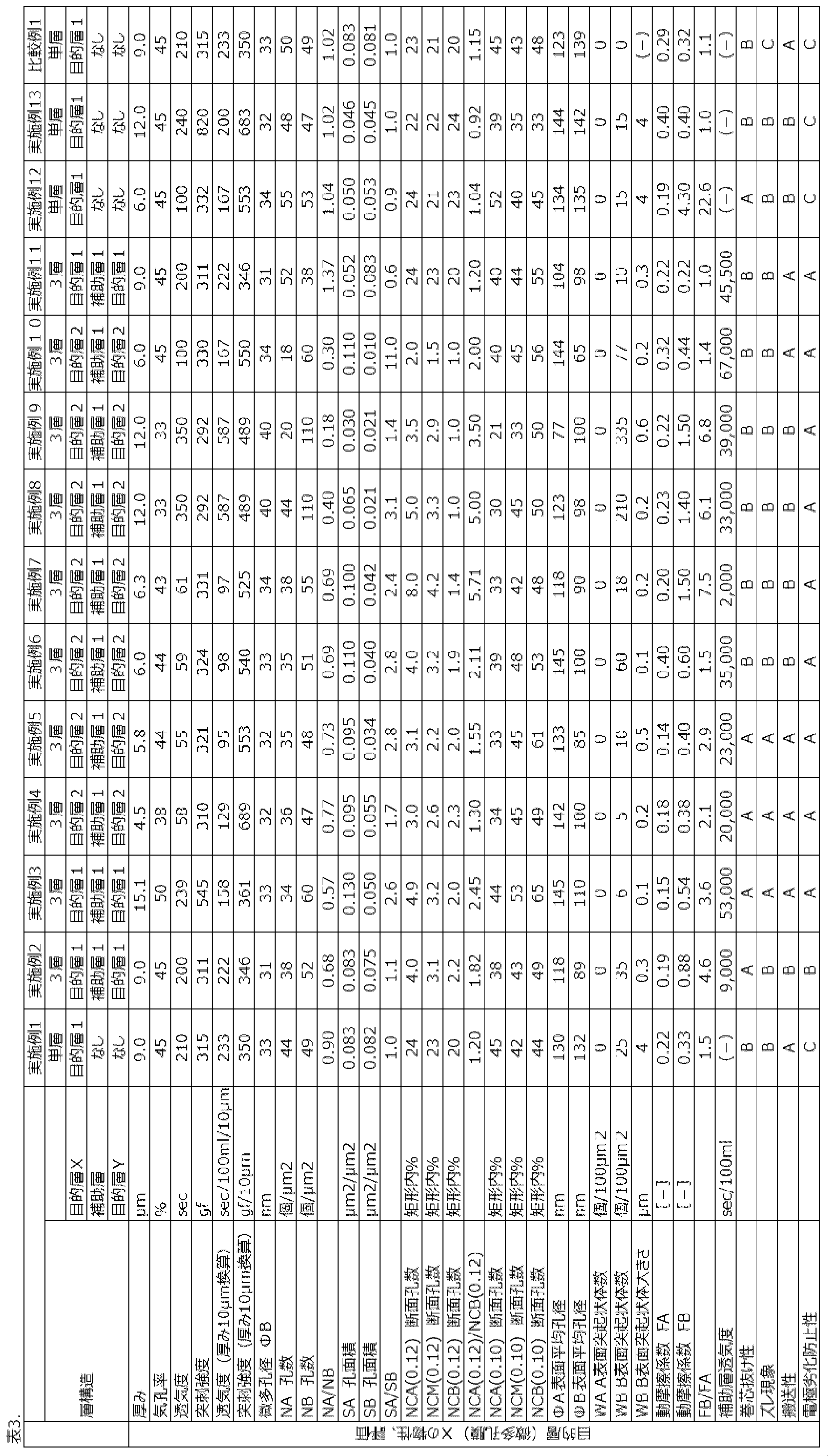

2 キャスト装置の冷却ロール(キャストロール)
3 溶融フィルム原反
3i 目的層X
3o 目的層Y
10 巻取機
11 巻取り上軸
12 巻取り下軸
13 ピンチロール
14 繰出し機
20 ピン
21 微多孔膜
22 ピンI
23 ピンII
24 微多孔膜の端部
30 微多孔膜
31 巻き取り軸
40 装置
41 固定バー
42 駆動巻取軸
43 微多孔膜
44 巻ずれ
60 微多孔膜の断面
61 A表面近傍を示す矩形
62 B表面近傍を示す矩形
63 中央付近を示す矩形
Claims (32)
- 表面A及び前記表面Aとは反対側の表面Bを有する、微多孔膜であって、
前記表面Aの動摩擦係数(FA)に対する、前記表面Bの動摩擦係数(FB)の比(FB/FA)が、1.2~20の範囲内である、微多孔膜。 - 前記表面A上の1μm2あたりの孔数(NA)が10個/μm2~100個/μm2であり、前記表面B上の1μm2あたりの孔数(NB)が20個/μm2~200個/μm2であり、NA/NBが0.2~0.98であり、前記表面A上の1μm2あたりの孔の面積の総和(SA)が0.02μm2~0.5μm2であり、前記表面B上の1μm2あたりの孔の面積の総和(SB)が0.01μm2~0.3μm2であり、SA/SBが1.1~10である、請求項1に記載の微多孔膜。
- 単独層から成る微多孔膜であって、
前記微多孔膜の厚みが3μm~18μmであり、
前記微多孔膜の一方の表面を表面Aとし、他方の表面を表面Bとし、表面A1μm2あたりの孔数をNAとし、表面B1μm2あたりの孔数をNBとしたとき、NAが10個/μm2~100個/μm2であり、NBが20個/μm2~200個/μm2であり、NA/NBが0.2~0.96であり、かつ
表面A1μm2あたりの孔の面積の総和をSAとし、表面B1μm2あたりの孔の面積の総和をSBとしたとき、SAが0.02μm2/μm2~0.5μm2/μm2であり、SBが0.01μm2/μm2~0.3μm2/μm2であり、SA/SBが1.1~10である、微多孔膜。 - 表面Aの動摩擦係数(FA)に対する表面Bの動摩擦係数(FB)の比FB/FAが1.2以上である、請求項3に記載の微多孔膜。
- 前記表面Bは複数の突起状体を有し、前記表面Bの100μm2あたりの前記突起状体の個数(WB)が0.2個/100μm2~1000個/100μm2の範囲内である、請求項1~4のいずれか一項に記載の微多孔膜。
- 表面A及び前記表面Aとは反対側の表面Bを有する、微多孔膜であって、
前記表面Bは複数の突起状体を有し、前記表面Bの100μm2あたりの前記突起状体の個数(WB)が0.2個/100μm2~1000個/100μm2の範囲内である、微多孔膜。 - 前記表面A上の1μm2あたりの孔数(NA)が10個/μm2~100個/μm2であり、前記表面B上の1μm2あたりの孔数(NB)が20個/μm2~200個/μm2であり、NA/NBが0.2~0.98であり、前記表面A上の1μm2あたりの孔の面積の総和(SA)が0.02μm2~0.5μm2であり、前記表面B上の1μm2あたりの孔の面積の総和(SB)が0.01μm2~0.3μm2であり、SA/SBが1.1~10である、請求項6に記載の微多孔膜。
- 表面Aの動摩擦係数(FA)に対する表面Bの動摩擦係数(FB)の比FB/FAが1.2以上である、請求項6又は7に記載の微多孔膜。
- 表面Aの動摩擦係数(FA)が0.3以下であり、かつ表面Bの動摩擦係数(FB)が0.9以下である、請求項1~8のいずれか一項に記載の微多孔膜。
- 前記微多孔膜の厚みが3μm~18μm、気孔率が20%~75%、厚み10μmに換算した突刺強度が300gf/10μm以上、厚み10μmに換算した透気度が30sec/100ml/10μm~1000sec/100ml/10μmである、請求項1~9のいずれか一項に記載の微多孔膜。
- 前記表面Aは複数の突起状体を有し、前記表面Aの100μm2あたりの前記突起状体の個数をWAとし、前記表面Bは複数の突起状体を有し、前記表面Bの100μm2あたりの前記突起状体の個数をWBとすると、WAが0.2個/100μm2未満であり、かつ、WB>10×WAである、請求項1~10のいずれか一項に記載の微多孔膜。
- 前記表面Bは複数の突起状体を有し、前記表面Bを正面から観察したときの前記表面Bの突起状体の大きさが0.01μm~5μmの範囲内である、請求項1~11のいずれか一項に記載の微多孔膜。
- 前記表面Bは複数の突起状体を有し、前記表面Bの突起状体がポリエチレン又はポリプロピレンを主成分として含有する、請求項1~12のいずれか一項に記載の微多孔膜。
- 前記微多孔膜の断面において、表面A近傍で観察される孔の総数のうち、孔径が0.12μm以上の孔の数の割合(%)をNCA(0.12)、断面方向中央付近で観察される孔の総数のうち、孔径が0.12μm以上の孔の数の割合(%)をNCM(0.12)、表面B近傍で観察される孔の総数のうち、孔径が0.12μm以上の孔の数の割合(%)をNCB(0.12)としたとき、
NCA(0.12)>NCM(0.12)>NCB(0.12)であり、
但し、前記微多孔膜の断面の厚み方向において、表面Aの位置を0%、表面Bの位置を100%としたとき、前記表面A近傍とは0%~10%の領域、前記中央付近とは45%~55%の領域、前記表面B近傍とは90%~100%の領域を意味する、請求項1~13のいずれか一項に記載の微多孔膜。 - NCA(0.12)/NCB(0.12)>1.2を更に満たす、請求項14に記載の微多孔膜。
- NCA(0.12)は2%~5%、NCB(0.12)は0.5%~3.0%である、請求項14又は15に記載の微多孔膜。
- 前記微多孔膜の断面において、表面A近傍で観察される孔の総数のうち、孔径が0.1μm未満の孔の数の割合(%)をNCA(0.10)、断面方向中央付近で観察される孔の総数のうち、孔径が0.10μm未満の孔の数の割合(%)をNCM(0.10)、表面B近傍で観察される孔の総数のうち、孔径が0.10μm未満の孔の数の割合(%)をNCB(0.10)としたとき、
NCA(0.10)<NCM(0.10)<NCB(0.10)であり、
但し、前記微多孔膜の断面の厚み方向において、表面Aの位置を0%、表面Bの位置を100%としたとき、前記表面A近傍とは0%~10%の領域、前記中央付近とは45%~55%の領域、前記表面B近傍とは90%~100%の領域を意味する、請求項1~16のいずれか一項に記載の微多孔膜。 - 前記微多孔膜の前記表面A及び前記表面Bが、ポリエチレンを主成分として含有する、請求項1~13のいずれか一項に記載の微多孔膜。
- 前記微多孔膜の前記表面A及び前記表面Bが、ポリエチレンを主成分として含有し、前記ポリエチレンは、粘度平均分子量が2,000,000以上の成分を5質量%~30質量%含む、請求項1~14のいずれか一項に記載の微多孔膜。
- 前記微多孔膜の前記表面A及び前記表面Bが、ポリエチレンを主成分として含有し、かつ前記ポリエチレンが、粘度平均分子量500,000~900,000の超高分子量ポリエチレンを10質量%以上含有する、請求項1~15のいずれか一項に記載の微多孔膜。
- 前記微多孔膜の前記表面A及び前記表面Bが、粘度平均分子量1,000,000以上の超高分子量成分を20質量%以上含む、請求項1~16のいずれか一項に記載の微多孔膜。
- 前記微多孔膜の厚み10μmに換算した突刺強度が、300gf/10μm以上、1200gf/10μm以下である、請求項1~17のいずれか一項に記載の微多孔膜。
- 前記微多孔膜の、表面Bに観察される孔の平均孔径をΦBとしたとき、ΦBが、5nm~100nmの範囲内である、請求項11~18のいずれか一項に記載の微多孔膜。
- 前記微多孔膜の表面Aに観察される孔の平均孔径をΦA、表面Bに観察される孔の平均孔径をΦBとしたとき、ΦA>ΦBである、請求項11~19のいずれか一項に記載の微多孔膜。
- 請求項1~20のいずれか一項に記載の微多孔膜を含む、リチウムイオン2次電池用セパレータ。
- 微多孔膜を製造する方法であって、以下:
湿式法により、表面A及び前記表面Aとは反対側の表面Bを有する微多孔膜を形成する工程と;
前記微多孔膜の表面Bに、繊維径1μm~10μmのポリエチレン又はポリプロピレンを主成分として含有する突起状体を貼り付ける工程とを含む、方法。 - 微多孔膜を製造する方法であって、以下:
表面A及び前記表面Aとは反対側の表面Bを有する目的層と、補助層との共押出によって、前記目的層及び前記目的層の前記表面B上に前記補助層を有する微多孔膜原反を成形する共押出工程であって、前記目的層は、前記目的層の全質量を基準として40質量%以上の可塑剤を含有し、前記補助層は、前記補助層の全質量を基準として60質量%以下の可塑剤を含有する、共押出工程と;
前記共押出工程の後に、以下(a)~(c):
(a)前記微多孔膜原反を延伸する延伸工程と;
(b)抽出溶媒の存在下、前記微多孔膜原反から前記可塑剤を抽出する抽出工程と; (c)前記目的層の前記表面Bから前記補助層を剥離して、前記目的層を微多孔膜として得る剥離工程と
を任意の順序で含む、方法。 - 前記目的層は単独層である、請求項23に記載の方法。
- 前記目的層の原料樹脂が、ポリエチレンを主成分として含有し、かつ前記補助層の原料樹脂が、ポリプロピレンを主成分として含有する、請求項23又は24に記載の方法。
- 前記剥離工程後に、前記補助層は、透気度が3000sec/100ml以上の微多孔膜、又は無孔膜である、請求項23~25のいずれか一項に記載の方法。
- 前記目的層中の前記可塑剤の含有量が、90質量%以下であり、かつ/又は前記補助層中の前記可塑剤の含有量が、0質量%より大きい、請求項23~26のいずれか一項に記載の方法。
- 前記剥離工程後に、前記目的層に塗料を塗工する塗工工程をさらに含む、請求項23~27のいずれか一項に記載の方法。
Priority Applications (5)
| Application Number | Priority Date | Filing Date | Title |
|---|---|---|---|
| EP21747554.0A EP4098437A4 (en) | 2020-01-31 | 2021-01-29 | Microporous film, and method for producing same |
| US17/795,210 US12370772B2 (en) | 2020-01-31 | 2021-01-29 | Microporous film, and method for producing same |
| JP2021574734A JP7437421B2 (ja) | 2020-01-31 | 2021-01-29 | 微多孔膜及びその製造方法 |
| KR1020227024065A KR102861550B1 (ko) | 2020-01-31 | 2021-01-29 | 미다공막 및 그의 제조 방법 |
| CN202180011714.0A CN115023460B (zh) | 2020-01-31 | 2021-01-29 | 微多孔膜及其制造方法 |
Applications Claiming Priority (4)
| Application Number | Priority Date | Filing Date | Title |
|---|---|---|---|
| JP2020-015775 | 2020-01-31 | ||
| JP2020015775 | 2020-01-31 | ||
| JP2020-111899 | 2020-06-29 | ||
| JP2020111899 | 2020-06-29 |
Publications (1)
| Publication Number | Publication Date |
|---|---|
| WO2021153792A1 true WO2021153792A1 (ja) | 2021-08-05 |
Family
ID=77078299
Family Applications (1)
| Application Number | Title | Priority Date | Filing Date |
|---|---|---|---|
| PCT/JP2021/003415 Ceased WO2021153792A1 (ja) | 2020-01-31 | 2021-01-29 | 微多孔膜及びその製造方法 |
Country Status (6)
| Country | Link |
|---|---|
| US (1) | US12370772B2 (ja) |
| EP (1) | EP4098437A4 (ja) |
| JP (1) | JP7437421B2 (ja) |
| KR (1) | KR102861550B1 (ja) |
| CN (1) | CN115023460B (ja) |
| WO (1) | WO2021153792A1 (ja) |
Cited By (2)
| Publication number | Priority date | Publication date | Assignee | Title |
|---|---|---|---|---|
| EP4205947A1 (en) * | 2021-12-29 | 2023-07-05 | W-Scope Korea Co., Ltd. | Stretching apparatus for manufacturing separator and method of manufacturing separator using the same |
| WO2023127508A1 (ja) * | 2021-12-27 | 2023-07-06 | パナソニックエナジ-株式会社 | 非水電解質二次電池 |
Families Citing this family (1)
| Publication number | Priority date | Publication date | Assignee | Title |
|---|---|---|---|---|
| CN117202981A (zh) * | 2021-03-05 | 2023-12-08 | 赛尔格有限责任公司 | 热稳定膜 |
Citations (11)
| Publication number | Priority date | Publication date | Assignee | Title |
|---|---|---|---|---|
| JPH05258741A (ja) | 1992-03-11 | 1993-10-08 | Matsushita Electric Ind Co Ltd | 非水電解質二次電池用セパレータ |
| JPH11123799A (ja) | 1997-10-24 | 1999-05-11 | Ube Ind Ltd | 積層多孔質フイルム |
| WO2004024808A1 (ja) * | 2002-09-12 | 2004-03-25 | Teijin Limited | ポリ−(メタフェニレン イソフタルアミド)からなる多孔膜およびその製造方法 |
| JP2004099799A (ja) * | 2002-09-11 | 2004-04-02 | Asahi Kasei Chemicals Corp | ポリオレフィン製微多孔膜捲回物 |
| JP2009001817A (ja) * | 2008-08-12 | 2009-01-08 | Asahi Kasei Corp | 通流体性微多孔フィルム及びその製造方法 |
| JP2009114434A (ja) | 2007-10-15 | 2009-05-28 | Toray Ind Inc | 多孔性フィルム |
| JP2010036355A (ja) | 2008-07-31 | 2010-02-18 | Asahi Kasei E-Materials Corp | 多層微多孔膜の製造方法および非水電解液二次電池用セパレータ |
| JP2011051330A (ja) | 2009-08-06 | 2011-03-17 | Asahi Kasei E-Materials Corp | 微多孔膜積合体及びその製造方法、並びに微多孔膜の製造方法 |
| JP5596768B2 (ja) | 2005-08-04 | 2014-09-24 | 東レバッテリーセパレータフィルム株式会社 | ポリエチレン微多孔膜及び電池用セパレータ |
| JP2017029338A (ja) | 2015-07-31 | 2017-02-09 | 株式会社サンセイアールアンドディ | 遊技機 |
| WO2018180713A1 (ja) * | 2017-03-30 | 2018-10-04 | 東レ株式会社 | ポリオレフィン微多孔膜およびそれを用いた電池 |
Family Cites Families (21)
| Publication number | Priority date | Publication date | Assignee | Title |
|---|---|---|---|---|
| US4376046A (en) * | 1981-06-01 | 1983-03-08 | Deutsch Daniel Harold | System with asymmetric microporous membrane for the circulation or movement of solutions |
| US5968643A (en) * | 1997-09-16 | 1999-10-19 | Kimberly-Clark Worldwide, Inc. | Microporous film with improved properties |
| JP4229504B2 (ja) * | 1999-01-06 | 2009-02-25 | 旭化成株式会社 | 通流体性微多孔フイルム及びその製造方法 |
| US20060141238A1 (en) | 2002-09-12 | 2006-06-29 | Takeshi Sasaki | Porous membrane of poly(metaphenylene isophthalamide) and process for producing the same |
| JP5202826B2 (ja) | 2005-08-04 | 2013-06-05 | 東レバッテリーセパレータフィルム株式会社 | ポリエチレン微多孔膜及びその製造方法並びに電池用セパレータ |
| JP4916195B2 (ja) * | 2006-03-09 | 2012-04-11 | 三菱樹脂株式会社 | 積層型多孔性フィルム |
| JP5245483B2 (ja) | 2008-03-24 | 2013-07-24 | 東レ株式会社 | ポリプロピレン多孔性フィルム、その製造方法、および蓄電デバイス |
| KR20160111547A (ko) | 2009-03-09 | 2016-09-26 | 아사히 가세이 이-매터리얼즈 가부시키가이샤 | 적층 세퍼레이터, 폴리올레핀 미다공막 및 축전 디바이스용 세퍼레이터 |
| WO2010147149A1 (ja) | 2009-06-19 | 2010-12-23 | 三菱樹脂株式会社 | 多孔性ポリプロピレンフィルム |
| EP2623309A4 (en) * | 2010-10-01 | 2015-01-28 | Mitsubishi Plastics Inc | LAMINATED POROUS FILM, SEPARATOR FOR ONE BATTERY AND BATTERY |
| JP5768359B2 (ja) * | 2010-11-17 | 2015-08-26 | ソニー株式会社 | 耐熱性微多孔膜、電池用セパレータ及びリチウムイオン二次電池 |
| WO2013146403A1 (ja) * | 2012-03-30 | 2013-10-03 | 東レバッテリーセパレータフィルム株式会社 | ポリオレフィン多層微多孔膜 |
| US9627673B2 (en) | 2012-11-27 | 2017-04-18 | W. L. Gore & Associates, Co., Ltd. | Second battery and separator used therein |
| BR112015014094A2 (pt) * | 2012-12-13 | 2017-07-11 | 3M Innovative Properties Co | construções para dispositivos de separação de fluidos por membrana |
| US20160214069A1 (en) * | 2013-09-26 | 2016-07-28 | The Regents Of The University Of Colorado, A Body Corporate | Novel nano-patterned thin film membranes and thin film composite membranes, and methods using same |
| JP6497082B2 (ja) * | 2014-01-28 | 2019-04-10 | 東レ株式会社 | 多孔性積層体 |
| CN106463679B (zh) | 2014-06-10 | 2019-04-19 | 东丽株式会社 | 电池用隔膜及其制造方法 |
| KR101713533B1 (ko) * | 2014-08-29 | 2017-03-08 | 스미또모 가가꾸 가부시키가이샤 | 적층체, 적층체를 포함하는 비수 전해액 이차 전지용 세퍼레이터 및 비수 전해액 이차 전지용 세퍼레이터를 포함하는 비수 전해액 이차 전지 |
| EP3340342B1 (en) * | 2016-12-20 | 2020-10-28 | Asahi Kasei Kabushiki Kaisha | Separator for power storage device, laminated body, roll, lithium-ion secondary battery or power storage device using it |
| JP6965092B2 (ja) * | 2017-10-13 | 2021-11-10 | 旭化成株式会社 | ポリオレフィン微多孔膜及びこれを用いたリチウムイオン二次電池 |
| JP2019206773A (ja) | 2018-05-29 | 2019-12-05 | 株式会社イノアックコーポレーション | フィルタおよびこれを用いたマスク |
-
2021
- 2021-01-29 US US17/795,210 patent/US12370772B2/en active Active
- 2021-01-29 KR KR1020227024065A patent/KR102861550B1/ko active Active
- 2021-01-29 EP EP21747554.0A patent/EP4098437A4/en active Pending
- 2021-01-29 WO PCT/JP2021/003415 patent/WO2021153792A1/ja not_active Ceased
- 2021-01-29 JP JP2021574734A patent/JP7437421B2/ja active Active
- 2021-01-29 CN CN202180011714.0A patent/CN115023460B/zh active Active
Patent Citations (11)
| Publication number | Priority date | Publication date | Assignee | Title |
|---|---|---|---|---|
| JPH05258741A (ja) | 1992-03-11 | 1993-10-08 | Matsushita Electric Ind Co Ltd | 非水電解質二次電池用セパレータ |
| JPH11123799A (ja) | 1997-10-24 | 1999-05-11 | Ube Ind Ltd | 積層多孔質フイルム |
| JP2004099799A (ja) * | 2002-09-11 | 2004-04-02 | Asahi Kasei Chemicals Corp | ポリオレフィン製微多孔膜捲回物 |
| WO2004024808A1 (ja) * | 2002-09-12 | 2004-03-25 | Teijin Limited | ポリ−(メタフェニレン イソフタルアミド)からなる多孔膜およびその製造方法 |
| JP5596768B2 (ja) | 2005-08-04 | 2014-09-24 | 東レバッテリーセパレータフィルム株式会社 | ポリエチレン微多孔膜及び電池用セパレータ |
| JP2009114434A (ja) | 2007-10-15 | 2009-05-28 | Toray Ind Inc | 多孔性フィルム |
| JP2010036355A (ja) | 2008-07-31 | 2010-02-18 | Asahi Kasei E-Materials Corp | 多層微多孔膜の製造方法および非水電解液二次電池用セパレータ |
| JP2009001817A (ja) * | 2008-08-12 | 2009-01-08 | Asahi Kasei Corp | 通流体性微多孔フィルム及びその製造方法 |
| JP2011051330A (ja) | 2009-08-06 | 2011-03-17 | Asahi Kasei E-Materials Corp | 微多孔膜積合体及びその製造方法、並びに微多孔膜の製造方法 |
| JP2017029338A (ja) | 2015-07-31 | 2017-02-09 | 株式会社サンセイアールアンドディ | 遊技機 |
| WO2018180713A1 (ja) * | 2017-03-30 | 2018-10-04 | 東レ株式会社 | ポリオレフィン微多孔膜およびそれを用いた電池 |
Non-Patent Citations (1)
| Title |
|---|
| See also references of EP4098437A4 |
Cited By (3)
| Publication number | Priority date | Publication date | Assignee | Title |
|---|---|---|---|---|
| WO2023127508A1 (ja) * | 2021-12-27 | 2023-07-06 | パナソニックエナジ-株式会社 | 非水電解質二次電池 |
| EP4205947A1 (en) * | 2021-12-29 | 2023-07-05 | W-Scope Korea Co., Ltd. | Stretching apparatus for manufacturing separator and method of manufacturing separator using the same |
| US12230831B2 (en) | 2021-12-29 | 2025-02-18 | W-Scope Korea Co., Ltd. | Stretching apparatus for manufacturing separator and method of manufacturing separator using the same |
Also Published As
| Publication number | Publication date |
|---|---|
| US12370772B2 (en) | 2025-07-29 |
| JPWO2021153792A1 (ja) | 2021-08-05 |
| CN115023460B (zh) | 2024-04-05 |
| US20230056490A1 (en) | 2023-02-23 |
| JP7437421B2 (ja) | 2024-02-22 |
| KR20220115606A (ko) | 2022-08-17 |
| EP4098437A1 (en) | 2022-12-07 |
| CN115023460A (zh) | 2022-09-06 |
| KR102861550B1 (ko) | 2025-09-19 |
| EP4098437A4 (en) | 2023-11-15 |
Similar Documents
| Publication | Publication Date | Title |
|---|---|---|
| US9853272B2 (en) | Laminated polyolefin microporous membrane including propylene-α-olefin copolymer and method of producing the same | |
| JP5450929B2 (ja) | ポリオレフィン多層微多孔膜、その製造方法、電池用セパレータ及び電池 | |
| KR101227325B1 (ko) | 다층 다공막 및 그의 제조 방법 | |
| KR101266607B1 (ko) | 폴리올레핀제 미다공막 및 권회물 | |
| JP4902455B2 (ja) | ポリオレフィン多層微多孔膜、その製造方法、電池用セパレータ及び電池 | |
| CN102264814B (zh) | 聚烯烃制微多孔膜 | |
| JP5813077B2 (ja) | 微多孔膜積合体及びその製造方法、並びに微多孔膜の製造方法 | |
| JP5717302B2 (ja) | 積層微多孔膜及び非水電解質二次電池用セパレータ | |
| JP5398016B2 (ja) | 微多孔膜及びその製造方法、並びに非水電解液2次電池用セパレータ | |
| JP7045862B2 (ja) | ポリオレフィン微多孔膜及びポリオレフィン微多孔膜の製造方法 | |
| KR20170019345A (ko) | 전지용 세퍼레이터 및 이의 제조 방법 | |
| JP7437421B2 (ja) | 微多孔膜及びその製造方法 | |
| KR20170016827A (ko) | 전지용 세퍼레이터 및 이의 제조 방법 | |
| JP2014012857A (ja) | 微多孔膜及びその製造方法、並びに非水電解液2次電池用セパレータ | |
| CN108623876A (zh) | 聚烯烃微多孔膜及聚烯烃微多孔膜的制备方法 | |
| JP5676286B2 (ja) | ポリオレフィン微多孔膜 | |
| JP2019199028A (ja) | 微多孔膜の製造方法およびそれを用いた微多孔膜 | |
| JP5189048B2 (ja) | 捲回体 | |
| JP2012022911A (ja) | 積層セパレータおよび蓄電デバイス |
Legal Events
| Date | Code | Title | Description |
|---|---|---|---|
| 121 | Ep: the epo has been informed by wipo that ep was designated in this application |
Ref document number: 21747554 Country of ref document: EP Kind code of ref document: A1 |
|
| ENP | Entry into the national phase |
Ref document number: 2021574734 Country of ref document: JP Kind code of ref document: A |
|
| ENP | Entry into the national phase |
Ref document number: 20227024065 Country of ref document: KR Kind code of ref document: A |
|
| NENP | Non-entry into the national phase |
Ref country code: DE |
|
| ENP | Entry into the national phase |
Ref document number: 2021747554 Country of ref document: EP Effective date: 20220831 |
|
| WWG | Wipo information: grant in national office |
Ref document number: 17795210 Country of ref document: US |