WO2021157134A1 - 制御システム - Google Patents
制御システム Download PDFInfo
- Publication number
- WO2021157134A1 WO2021157134A1 PCT/JP2020/038321 JP2020038321W WO2021157134A1 WO 2021157134 A1 WO2021157134 A1 WO 2021157134A1 JP 2020038321 W JP2020038321 W JP 2020038321W WO 2021157134 A1 WO2021157134 A1 WO 2021157134A1
- Authority
- WO
- WIPO (PCT)
- Prior art keywords
- control
- program
- node
- command
- unit
- Prior art date
- Legal status (The legal status is an assumption and is not a legal conclusion. Google has not performed a legal analysis and makes no representation as to the accuracy of the status listed.)
- Ceased
Links
Images

















Classifications
-
- G—PHYSICS
- G05—CONTROLLING; REGULATING
- G05B—CONTROL OR REGULATING SYSTEMS IN GENERAL; FUNCTIONAL ELEMENTS OF SUCH SYSTEMS; MONITORING OR TESTING ARRANGEMENTS FOR SUCH SYSTEMS OR ELEMENTS
- G05B19/00—Program-control systems
- G05B19/02—Program-control systems electric
- G05B19/04—Program control other than numerical control, i.e. in sequence controllers or logic controllers
- G05B19/042—Program control other than numerical control, i.e. in sequence controllers or logic controllers using digital processors
-
- G—PHYSICS
- G06—COMPUTING OR CALCULATING; COUNTING
- G06F—ELECTRIC DIGITAL DATA PROCESSING
- G06F13/00—Interconnection of, or transfer of information or other signals between, memories, input/output devices or central processing units
- G06F13/10—Program control for peripheral devices
- G06F13/102—Program control for peripheral devices where the program performs an interfacing function, e.g. device driver
-
- G—PHYSICS
- G05—CONTROLLING; REGULATING
- G05B—CONTROL OR REGULATING SYSTEMS IN GENERAL; FUNCTIONAL ELEMENTS OF SUCH SYSTEMS; MONITORING OR TESTING ARRANGEMENTS FOR SUCH SYSTEMS OR ELEMENTS
- G05B19/00—Program-control systems
- G05B19/02—Program-control systems electric
- G05B19/04—Program control other than numerical control, i.e. in sequence controllers or logic controllers
- G05B19/05—Programmable logic controllers, e.g. simulating logic interconnections of signals according to ladder diagrams or function charts
- G05B19/056—Programming the PLC
-
- Y—GENERAL TAGGING OF NEW TECHNOLOGICAL DEVELOPMENTS; GENERAL TAGGING OF CROSS-SECTIONAL TECHNOLOGIES SPANNING OVER SEVERAL SECTIONS OF THE IPC; TECHNICAL SUBJECTS COVERED BY FORMER USPC CROSS-REFERENCE ART COLLECTIONS [XRACs] AND DIGESTS
- Y02—TECHNOLOGIES OR APPLICATIONS FOR MITIGATION OR ADAPTATION AGAINST CLIMATE CHANGE
- Y02P—CLIMATE CHANGE MITIGATION TECHNOLOGIES IN THE PRODUCTION OR PROCESSING OF GOODS
- Y02P90/00—Enabling technologies with a potential contribution to greenhouse gas [GHG] emissions mitigation
- Y02P90/02—Total factory control, e.g. smart factories, flexible manufacturing systems [FMS] or integrated manufacturing systems [IMS]
Definitions
- the present invention relates to a control system that controls using a computer, for example, in the fields of factory automation (FA) and process automation (PA).
- FA factory automation
- PA process automation
- control systems using computers are introduced in manufacturing processes such as factories and production processes of chemical products.
- the control system is controlled by a computer such as a programmable logic controller (PLC) executing a computer program.
- PLC programmable logic controller
- the processing outline of such a control system will be explained.
- the computer acquires information necessary for control such as temperature, pressure, and rotation speed from the sensor.
- the computer operates the actuator, the motor, and the like based on the information.
- the content to be controlled is defined in the program, and the computer controls by executing the program. Control needs to be performed at an appropriate timing, and the performance and degree of control at an appropriate timing are called "punctuality".
- Patent Document 1 sequential control logic (various judgments, etc.) is executed by PLC, complicated arithmetic processing (numerical arithmetic such as convergence arithmetic) is executed on a general-purpose OS, and functions to be processed are distributed.
- the plant control system is disclosed.
- control system is required to continue operating. Therefore, the control system is made redundant by using two or more computers, and the operation of the control system is continued even if one computer fails.
- the program executed by each computer needs to have the performance of synchronizing the timing and information with the programs of other computers and not impairing the punctuality even in the event of a failure, which is difficult.
- Patent Document 1 does not disclose a technique for changing a control system program, a computer, or the like while operating a control system that requires such high punctuality.
- the present invention has been made in view of the above circumstances, and an object of the present invention is to enable changes in resources used in a control system without stopping the control system while maintaining punctuality. ..
- the control system of one aspect of the present invention is connected to at least one control node and one or more controlled devices, and at least one capable of communicating with the control node via a network. It is composed of I / O nodes.
- the control node includes a first operating system and a first processor that executes at least one control program on the first operating system.
- the I / O node has a second operating system that is more punctual than the first operating system, and a second processor that executes at least one I / O program on the second operating system.
- the control program of the control node has a determination execution unit that generates a control command based on the state control preset for the device to be controlled and transmits the control command to the I / O node.
- the I / O program of the I / O node has a control command execution unit that stores the control command received from the control node in a storage unit and executes processing related to the controlled device according to the control command stored in the storage unit. ..
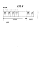
- Each I / O program when one I / O node is used and when the control cycle is staggered by using two I / O nodes (normal, standby) according to the fourth embodiment of the present invention is a chart which shows the example of the execution timing of.
- FIG. 1 is a block diagram showing an example of the overall configuration of the control system according to the first embodiment.
- the control system 100 shown in FIG. 1 includes a control node 1, an I / O node 2, an HMI node 3, a device 4 to be controlled, and a network 5 in which each node is communicably connected to each other.
- a control node 1 there is at least one control node 1 and at least one I / O node 2.
- the device 4 is, for example, a device used as a production facility in a factory, and the goal of the control system 100 is to make the device 4 perform a desired operation.
- the device 4 has a sensor 40 and an actuator 41.
- FIG. 1 shows only one sensor 40 and one actuator 41, in reality, there may be a plurality of sensors 40 and only one of the sensors 40 and the actuator 41.
- the sensor 40 is a device for grasping the state of the device 4 and the environment around it.
- the actuator 41 is a device for causing the device 4 to perform an actual operation or change the operation.
- Examples of the sensor 40 include a thermometer, a flow meter, a voltmeter, a switch, a video camera, a counter, and the like.
- Examples of the actuator 41 include motors, cylinders, electromagnets, relays, LEDs, lamps, buzzers and the like. As a matter of course, neither the sensor 40 nor the actuator 41 is limited to the above-mentioned example.
- the I / O node 2 is a computer composed of a CPU 20 (first processor), a storage device 21 (example of a storage unit), a network interface 22, and a memory 23.
- the HMI node (Human Machine Interface) 3 is a computer composed of a CPU 30, a storage device 31, a network interface 32, and a memory 33.
- the CPU 10 reads the general-purpose OS 14 (first operating system) from the storage device 11 onto the memory 13 and executes it. Further, the CPU 10 executes one or more control programs 7 on the general-purpose OS 14.
- the storage device 11 stores various tables and the like, which will be described later.
- the CPU 20 reads the real-time OS 24 (second operating system) from the storage device 21 onto the memory 23 and executes it. Further, the CPU 20 executes the I / O program 8 on the real-time OS 24.
- the storage device 21 stores the source list 87 and the like, which will be described later. Further, the I / O node 2 further has an I / O interface 25, and is connected to the device 4 by a cable 6.
- Specific examples of the cable 6 connecting the I / O interface 25 and the device 4 and the communication method between them include a method of directly wiring the device 4 via a screw terminal and an interface of the device 4.
- a method of communicating with the device 4 according to a specified protocol is assumed. In the present embodiment, any method may be used as long as the latency (delay) is small and communication with the sensor 40 and the actuator 41 of the device 4 is possible.
- Specific examples of the standard used for communication include USB (Universal Serial Bus), RS-232, and Ethernet (registered trademark), which can also be realized by wireless communication using Bluetooth (registered trademark) and the like.
- the CPU 30 reads the general-purpose OS 34 from the storage device 31 onto the memory 33 and executes it.
- the CPU 30 also executes the HMI program 9 on the general-purpose OS 34.
- the HMI node 3 includes a user interface 35 such as a display 35A and a keyboard 35B.
- Control node 1, I / O node 2, and HMI node 3 are connected to network 5 through their respective network interfaces 12, 22, and 32.
- Specific examples of the communication method of the network 5 include Ethernet (registered trademark) and CAN (Controller Area Network) (registered trademark).
- Ethernet registered trademark
- CAN Controller Area Network
- the control program 7, the I / O program 8, and the HMI program 9 communicate with each other using a protocol such as UDP over IP capable of one-to-one and one-to-many communication.
- the HMI program 9 has a plurality of screens for the administrator 36 of the control system 100 to set and confirm the state of the control system 100.
- the screen is implemented as a GUI (Graphical User Interface) and is operated by the administrator 36 of the control system 100 via the user interface 35.
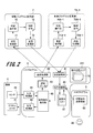
- FIG. 2 shows how the HMI program 9 transmits the switching signal generated by the switching signal transmission screen 90 to the command switching unit 84 of the I / O program 8.
- the switching signal transmission screen 90 will be described in detail in FIG. 11 described later.
- the command switching unit 84 registers the source information of the received control command 73 in the source list 87.
- the transmission data 83 is a telegram that describes information generated by the control command execution unit 80 of the I / O program 8 and transmitted to the judgment execution unit 70 of the control program 7 in accordance with the control command 73.
- the transmission data 83 includes the voltage value of the sensor 40, the value of the result calculated by the control command execution unit 80, and the like.
- the determination execution unit 70 acquires necessary information such as the status of the device 4 by receiving the contents of the transmission data 83.
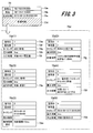
- FIG. 3 is a chart showing an example of the information contained in the control command 73.
- the control command 73 includes a source field 73a, a destination field 73b, a generation date / time field 73c, and a control content field 73d.
- the source field 73a stores the IP address and the port number that identify the control program 7 that generated the control command 73.
- the destination field 73b stores an IP address and a port number that identify the I / O program 8 in which the control program should be executed.
- the generation date / time column 73c stores the date and time when the control command 73 was generated.
- the control content column 73d stores the control content of the control command 73.
- the content of the timing can be specified in various cases such as when it is executed periodically at regular intervals, when conditions such as the state of the sensor are satisfied, and when the specified time is reached.
- the maximum time column 73h holds the maximum time (FIG. 8 described later) that can be allowed for processing one control command 73. If the maximum time column 73h is blank, it indicates that the maximum time has not been set.
- the control content columns 73d (1) to 73d (6) show specific examples of the control content for each process to be executed.
- the control content column 73d (1) is an example in the case of performing input processing, that is, information acquisition from the sensor 40.
- the control content field 73d (1) includes an input processing field 73i and holds an object for which information is to be acquired.
- the control content column 73d (2) is an example in the case of performing a calculation process, that is, a calculation process such as a moving average of the output value of the sensor 40.
- the control content column 73d (2) includes a calculation processing column 73j, and holds the content of the calculation process.
- the control content column 73d (3) is an example of a transmission process, that is, a case where information is transmitted to the control program 7.
- the control content column 73d (3) includes a transmission processing column 73k, and holds an object to be transmitted.
- the control content column 73d (4) is an example in the case of performing output processing, that is, operating an actuator or the like.
- the control content column 73d (4) includes an output processing column 73l, and holds a command ID to be operated and the content of the operation.
- the control content column 73d (5) is an example in the case of performing the control cycle setting process, that is, the setting related to the control cycle described later.
- the control content column 73d (5) includes a control cycle setting column 73m, and holds a designated control cycle and start timing.
- the control content column 73d (6) is an example of a stop process, that is, a case where the execution of the specific control command 73 is stopped.
- the control content column 73d (6) includes a cancel processing column 73n, and holds a command ID to be canceled.
- FIG. 4 is a chart showing an example of the information contained in the transmission data 83.
- the transmission data 83 includes a transmission source column 83a, a transmission date / time column 83b, a command ID column 83c, and a data column 83d.
- the source field 83a stores an IP address and a port number that identify the I / O program 8 that generated the transmission data 83.
- the transmission date / time field 83b stores the date and time when the transmission data 83 is transmitted by the I / O program 8.
- the command ID column 83c stores a command ID that identifies which control command 73 is instructed to transmit the transmission data 83.
- the data field 83d holds the contents (for example, target, value) of the data to be transmitted.
- the actual processing such as the operation of the device 4 is executed on the real-time OS 24 of the I / O node 2.
- the control command by the control command execution unit 80 of the I / O program 8 on the real-time OS 24 it is possible to achieve both complicated processing and highly punctual processing.
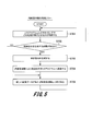
- FIG. 5 is a flowchart showing an example of a processing procedure by the determination execution unit 70.
- the determination execution unit 70 determines what kind of processing is to be executed by the I / O program 8 as the control system 100 at what timing (S701).
- the determination execution unit 70 determines whether or not it is necessary to generate a control command (S702), and if it is not necessary to generate a control command (NO in S702), proceeds to step S705.
- the determination execution unit 70 generates the control command 73 (S703) when it is necessary to generate the control command (YES in S702), and causes the transmission processing unit 72 to transmit the control command to the I / O program 8 (S704).
- the judgment execution unit 70 receives the new transmission data 83 from the reception processing unit 71 (S705).
- the determination execution unit 70 confirms that the transmission data 83 received by the reception processing unit 71 is transmitted from the I / O program 8 controlled by the transmission source column 83a (FIG. 4).
- the transmission data 83 is processed and used for the determination in the next step S701.
- the control program 7 constantly executes the processes of steps S701 to S705, and sends a control command 73 to the I / O node 2 (I / O program 8) at any time.
- the reception processing unit 81 of the I / O program 8 receives the control command 73 transmitted by the judgment execution unit 70 in step S704, the reception processing unit 81 passes the control command 73 to the command switching unit 84.
- the command switching unit 84 selects a control command 73 to be executed by a method described later, and passes the corresponding control command 73 to the control command execution unit 80.
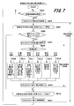
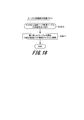
- FIG. 7 is a flowchart showing a procedure example of periodic processing of the control command execution unit 80.
- the control command execution unit 80 executes the control command within a fixed time cycle. This time cycle is called the "control cycle". The control cycle is set by the control command 73. First, the control command execution unit 80 determines whether or not the current time has reached the start time of the control cycle (S803), and if it has not yet reached the start time of the control cycle (NO in S803), the control cycle Continue monitoring the start time.
- control command execution unit 80 determines that it is time to start the control cycle (YES in S803), the control command execution unit 80 starts the operation of the cutoff timer for the control cycle (S804).
- the control command execution unit 80 determines the passage of time corresponding to the control cycle from the measurement time of the cutoff timer. If the process based on the control command 73 is not completed even after the time corresponding to the designated control cycle is exceeded, the control command execution unit 80 terminates (stops) the execution of the control command 73 being executed during that time.
- control command execution unit 80 starts a loop that executes the control command 73 in descending order of priority (S805).
- the control command execution unit 80 determines whether the current state satisfies the execution timing condition of the control command 73 (S806), and if the current state does not satisfy the execution timing condition (NO in S806), the step. Proceed to S816.
- control command execution unit 80 starts the operation of the cutoff timer for the maximum time (S807). If the process based on one control command 73 is not completed even after the specified maximum time is exceeded, the control command execution unit 80 terminates (stops) the execution of the control command 73 being executed at that time. The control command execution unit 80 does not start the cutoff timer when the maximum time column 73h is blank. Next, the control command execution unit 80 determines the processing type (control content) of the control command 73 (S808), and executes the processing of steps S809 to S814 according to the processing type.
- Step S809 is a step for input processing.
- the control command execution unit 80 acquires the information of the sensor 40 and stores the acquired information in a variable of the memory 23 so that the other steps can use it.
- Step S810 is a step for calculation processing.
- the control command execution unit 80 executes the calculation process and stores the result in a variable of the memory 23 so that the other steps can use it.
- Step S811 is a step for transmission processing.
- the control command execution unit 80 generates transmission data 83 including information to be transmitted, and causes the transmission processing unit 82 to transmit the transmission data 83 to all the control programs 7 on the network 5.
- Step S812 is a step for output processing.
- the control command execution unit 80 operates the actuator 41 of the device 4 to be controlled via the output processing unit 86.
- Step S813 is a step for setting processing.
- the control command execution unit 80 changes the control cycle.
- Step S814 is a step for canceling processing.
- the control command execution unit 80 deletes the control command
- control command execution unit 80 ends the cutoff timer for the maximum time (S815). During this time, the execution of one control command 73 ends.
- the control command execution unit 80 repeatedly executes the processes of steps S806 to S815 for all the control commands 73, and then ends the loop for executing the control commands 73 in descending order of priority (S816).
- control command execution unit 80 ends the cutoff timer for the control cycle (S817). Then, the control command execution unit 80 returns to step S803 and repeatedly executes the processes of steps S803 to S817.
- FIG. 8 shows an example of the execution timing of the control command 73 in the control command execution unit 80.
- the state of execution of the control command 73 in the periodic processing flow (FIG. 7) of the control command execution unit 80 is shown on the time axis. Due to the cutoff timer for the maximum time, each control command 73 (control commands 1 to 4 ...) Is not executed beyond the maximum time. Further, the cutoff timer for the control cycle does not cause each control command 73 (control commands 1 to 4 ...) to continue to be executed beyond the control cycle. Therefore, the control command execution unit 80 can execute the control command 73 with high punctuality.
- the control command execution unit 80 constantly executes the periodic processing flow, and all the control commands 73 are sequentially executed in order of priority for each control cycle. However, if the method can execute the control command 73 with high punctuality, this is used. Not exclusively.
- the control content of the control command 73 may be executed by the interrupt process. Further, the control command 73 being executed may be interrupted by the context switch so that the control command 73 having a higher priority is executed.
- the context switch is a function for saving and restoring the state of the CPU. Further, when the CPU 20 of the I / O node 2 has a plurality of cores, the control command processing may be executed in parallel.
- IP address and the port number are used as the information for identifying the control program 7 and the I / O program 8, if the information is used by the protocol on the network 5 and can uniquely identify the program on the network 5. Not limited to this. The same applies to the following description.
- control command execution unit 80 continues processing of the received control command 73 stored in the storage device 21, so that the control program can be changed without stopping the control system 100.
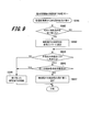
- FIG. 9 is a flowchart showing a procedure example of control command processing of the command switching unit 84.
- the command switching unit 84 When the command switching unit 84 receives the control command 73 from the reception processing unit 81 (S841), the command switching unit 84 starts the control command processing flow shown in FIG. First, the command switching unit 84 determines whether or not the control command 73 has been received for the first time (S842), and if the control command 73 has not been received for the first time (NO in S842), proceeds to step S844.
- step S843 the command switching unit 84 adds the IP address and the port number recorded in the source column 73a of the control command 73 received at the first activation of the control system 100 to the source list 87 (S843).
- step S843 the command switching unit 84 displays the source (IP address and port number) described in the source column 73a of the received control command 73 in the source list 87. It is determined whether or not it is included (S844). Then, when the source of the control command 73 is not included in the source list 87 (NO in S844), the command switching unit 84 proceeds to step S846, and the source is included in the source list 87. In the case (YES of S844), the process proceeds to step S845.
- the command switching unit 84 examines the received control commands 73 in the command storage area 211 in the order of newest generation date and time, and determines whether or not the control commands 73 having the same control contents have already been received (S845). Then, when the command switching unit 84 has received the control command 73 having the same content (YES in S845), the command switching unit 84 proceeds to step S846. If a NO determination is made in step S844 or a YES determination is made in step S845, the command switching unit 84 discards the received control command 73 (S846).
- the command switching unit 84 passes the control command 73 to the control command execution unit 80 (S847). That is, by switching the command switching unit 84, the control command executing unit 80 executes only the control command from the control program 7, which is the source of the first received control command 73. After the processing of step S846 or S847, the processing of the flowchart shown in FIG. 9 ends.
- FIG. 10 is a flowchart showing a procedure example of switching signal processing of the command switching unit 84.
- the manager 36 of the control system 100 shown in FIG. 2 operates the switching signal transmission screen 90 so that the control command 73A-1 generated by the control program 7A-1 is processed.
- the HMI program 9 transmits a switching signal to the command switching unit 84 based on the operation content for the switching signal transmission screen 90.
- the command switching unit 84 receives the switching signal from the HMI program 9 (S848), the command switching unit 84 starts the switching signal processing flow shown in FIG. That is, the command switching unit 84 changes the source information of the source list 87 to the source information included in the switching signal (S849).
- step S849 the process of the flowchart shown in FIG. 10 ends.
- FIG. 11 shows an example of the switching signal transmission screen 90 of the HMI program 9.
- the switching signal transmission screen 90 has an area 90a for inputting the IP address and port number of the I / O program 8, an area 90b for inputting the IP address and port number of the control program 7A-1 of the switching destination (after the change), and switching. It has a button 90c instructing the transmission of a signal.
- the administrator 36 of the control system 100 connects the changed control program 7A-1 to the network 5 and starts it, and then transmits a switching signal using the switching signal transmission screen 90, and the command switching unit 84 sends the control command 73A. Set to process -1.
- the transmission processing unit 82 of the I / O program 8 transmits the transmission data 83 to all the control programs on the network 5. Therefore, the control program 7 before the change and the control program 7A-1 after the change receive the same transmission data 83, and the control program 7 and the control program 7A-1 grasp the state of the device 4.
- the HMI program 9 is provided with the switching signal transmission screen 90, but the control node 1 and the I / O node 2 are provided with the same user interface, and the control program 7 and the I / O program 8 are provided with the switching signal transmission screen 90. May be provided. Further, it is sufficient that the administrator 36 of the control system 100 can notify the command switching unit 84 of the information specifying the control program 7A-1 to be switched, and the operation is not limited to the operation via the user interface. For example, it can be realized by connecting a storage device storing information for specifying the switching destination to the I / O node 2 and having the command switching unit 84 read this information.
- the command switching unit 84 adds the source information of the control command 73 at the time of initial reception to the source list 87, but the present invention is not limited to this example.
- the same step may be omitted, and the manager 36 of the control system 100 may specify the control system 100 via the HMI program 9 before the start of the control program 7.
- I / O node 2 exists in the network 5, but in reality, a plurality of I / O nodes may exist. Further, one control program may transmit control commands to a plurality of I / O programs.
- the resource is a program or a node (computer).
- control system 100 is connected to at least one control node (control node 1) and one or more controlled target devices (device 4) to form a network. It is composed of at least one I / O node (I / O node 2) capable of communicating with the control node via the control node.
- the control node includes a first operating system (general-purpose OS14) and a first processor (CPU10) that executes at least one control program (for example, control programs 7, 7A-1) on the first operating system. , Equipped with.
- the I / O node uses a second operating system (real-time OS24), which has higher punctuality than the first operating system, and at least one I / O program (for example, I / O program 8) as a second operating system. It includes a second processor (CPU 20) that runs on the system.
- the control program of the control node generates control commands (control commands 73, 73A-1) based on the state control set in advance for the device to be controlled, and transmits the control commands to the I / O node. (Judgment execution unit 70, 70A-1).
- control command execution unit when the control command execution unit (control command execution unit 80) stores a plurality of control commands in the storage unit (storage device 21), the control command execution unit (control command execution unit 80) stores a plurality of control commands. Executes the processes (input process, calculation process, transmission process, output process, setting process, stop process, etc.) specified in the control command in descending order of priority among a plurality of control commands in accordance with the control cycle. If the control command processing is not completed within the control cycle, the control command processing is stopped when the control cycle is exceeded.
- the I / O program (I / O program 8) is a control command to be executed from a plurality of control commands received from the plurality of control programs.
- a command switching unit (command switching unit 84) for selecting the above is provided.
- the command switching unit is configured to select a control command generated by the control program after switching from a plurality of control programs and transmit the control command to the control command execution unit (control command execution unit 80).
- Second embodiment> in the control system, a method of making the control node redundant by using a plurality of control nodes and automatically recovering to the redundant configuration after exchanging the failed control node will be described.
- the configuration management program 15 takes either a master or slave state. Only one configuration management program 15 in the master state exists on one network 5, and plays a role of distributing the corresponding data to the configuration management program 15 in the slave state in order to share the data necessary for control. Further, the instruction from the administrator 36 of the control system 100B is received through the HMI program 9.
- FIG. 13 is a block diagram showing an example of the overall configuration of the control system 100B according to the second embodiment.
- two control nodes 1B are used as control nodes 1B-1 and 1B-2.
- the control nodes 1B-1 and 1B-2 are connected to the I / O node 2 and the HMI node 3 via the network 5, respectively, as in the first embodiment.
- the control node 1B-1 includes a configuration management program 15B-1 and a control program 7B-1.
- the configuration management program 15B-1 includes a master selection unit 15B-1A, a program arrangement unit 15B-1B, an abnormality monitoring unit 15B-1C, a program registration unit 15B-1D, and a table synchronization unit 15B-1E (example of an information synchronization unit). It includes a control program management table 15B-1F and a control node management table 15B-1G.
- control node 1B-2 also includes the configuration management program 15B-2 and the control program 7B-2.
- the configuration management program 15B-2 includes a master selection unit 15B-2A, a program arrangement unit 15B-2B, an abnormality monitoring unit 15B-2C, a program registration unit 15B-2D, and a table synchronization unit 15B-2E (example of an information synchronization unit). It includes a control program management table 15B-2F and a control node management table 15B-2G.
- Control node 1B-3 is an example of a control node newly connected to restore the redundant configuration of the control system 100B.
- the control node 1B-3 has the same configuration as the control nodes 1B-1 and 1B-2. That is, the control node 1B-3 includes the configuration management program 15B-3 and the control program 7B-3.
- the configuration management program 15B-3 includes a master selection unit 15B-3A, a program arrangement unit 15B-3B, an abnormality monitoring unit 15B-3C, a program registration unit 15B-3D, and a table synchronization unit 15B-3E (example of an information synchronization unit). It includes a control program management table 15B-3F and a control node management table 15B-3G. The recovery of the redundant configuration using the control node 1B-3 will be described later.
- control node 1B When control nodes 1B-1, 1B-2 and 1B-3 are not distinguished, they are referred to as "control node 1B".
- the I / O node 2 executes the I / O program 8B in which the command switching unit 84 is changed to the command switching unit 84B. Further, the HMI node 3 executes the HMI program 9B in which a new screen is added to the HMI program 9 and the control program 7B.
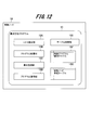
- the HMI program 9B has a control program registration screen 91, which is an operation screen by GUI, and a control node abnormality warning screen 92.
- Control program management table, control node management table] 14 and 15 show specific examples of each table of the configuration management program 15.
- FIG. 14 shows an example of the structure of the control program management table 15F used by the configuration management program 15.
- FIG. 15 shows an example of the structure of the control node management table 15G used by the configuration management program 15.
- the control program management table 15F includes a program ID column 15f-1, a storage destination column 15f-2, a type column 15f-3, and a configuration number column 15f-4.
- the program ID column 15f-1 stores a control program ID for uniquely identifying the control program.
- the save destination column 15f-2 stores information indicating the save destination location of the control program.
- the type column 15f-3 stores information indicating an execution method of the control system 100B.
- the configuration number column 15f-4 stores the number of control nodes used when executing the control program specified by the control program ID.
- the control node management table 15G includes a control node ID column 15g-1, a master / slave column 15g-2, an execution control program ID column 15g-3, and an execution enable / disable column 15g-4.
- the control node ID column 15g-1 stores a control node ID for uniquely identifying the control node.
- the master / slave column 15g-2 stores information indicating whether the state of the configuration management program (control node) is master or slave. There is only one control node in the master state per network. The master / slave information may be managed by another control node management table 15G instead of the control node management table 15G.
- the execution control program ID column 15g-3 stores a control program ID for uniquely identifying the control program being executed.
- the executability column 15g-4 stores information indicating whether the control program can be executed on the control node.
- FIG. 16 is a flowchart showing a procedure example of the start processing of the master selection unit 15A.
- the administrator 36 of the control system 100B starts the operation of the control nodes 1B-1 and 1B-2 by the user interface 35.
- the configuration management program 15B-1 starts the start flow of the master selection unit 15B-1A shown in FIG.
- the master selection unit 15B-1A of the control node 1B-1 determines whether or not the configuration management program (control node) in the master state exists on the network 5 (S1501).
- the master selection unit 15B-1A proceeds to step S1502 when the configuration management program 15 in the master state does not exist (NO in S1501), and steps S1502 when the configuration management program 15 in the master state exists (YES in S1501). Proceed to S1504.
- the master selection unit 15B-1A determines in step S1501 that the configuration management program 15 in the master state does not exist on the network 5 (NO in S1501), and sets the configuration management program 15B-1 as the master (S1502). ). Then, the master selection unit 15B-1A adds the information of its own control node 1B-1 to the control node management table 15B-1G by the table synchronization unit 15B-1E (S1503). After the process of step S1503, the process proceeds to step S1506.
- the master selection unit 15B-2A of the control node 1B-2 sets its own configuration management program 15B-2 as a slave (S1504). Then, the master selection unit 15B-2A notifies the master selection unit 15B-1A of the control node 1B-1 of the information of the control node 1B-2 (S1505).
- each master selection unit 15A of the configuration management programs 15B-1 and 15B-2 causes the abnormality monitoring unit 15C to start processing (S1506).
- the process of the abnormality monitoring unit 15C in step S1506 will be described later with reference to FIG. After the process of step S1506, the process of this flowchart ends.
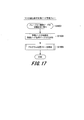
- FIG. 17 is a flowchart showing a procedure example of the control node management process of the master selection unit 15A.
- the master selection unit 15B-1A of the control node 1B-1 in the master state receives the information of the control node from the control node 1B-2 in the slave state (S1507)
- the control node management flow is started.
- the master selection unit 15B-1A additionally registers the received information of the control node 1B-2 in the control node management table 15B-1G by the table synchronization unit 15B-1E (S1508).
- the master selection unit 15B-1A causes the program arrangement unit 15B-1B to start the program arrangement flow shown in FIG. 21 (S1509).
- the control program is not registered in the control program management table 15B-1F, the control program is not arranged.
- the process of this flowchart ends.
- FIG. 18 is a flowchart showing a procedure example of the synchronization process of the table synchronization unit 15E.
- step S1523 of FIG. 21, which will be described later the contents of the control node management table 15B-1G are notified from the master state configuration management program 15B-1 to the table synchronization unit 15B-2E of the slave state configuration management program 15B-2. ..
- the table synchronization unit 15B-2E receives the contents of the control node management table 15B-1G (S1510)
- the table synchronization unit 15B-2E starts the synchronization flow shown in FIG. That is, the table synchronization unit 15B-2E stores the contents of the received control node management table 15B-1G in the control node management table 15B-2G (S1511).
- step S1511 the process of this flowchart ends.
- the table synchronization unit 15B-2E registers all the received information in the control node management table 15B-2G.
- the contents of the control node management table 15B-1G on the configuration management program 15B-1 in the master state are the contents of all the control node management tables 15G in the slave state. Is the same as.
- the configuration management program 15 starts executing the abnormality monitoring unit 15C, which will be described later, in step S1504.
- FIG. 19 shows an example of the control program registration screen 91.
- the administrator 36 of the control system 100B operates to arrange the execution file of the control program 7B in the storage device 31 of the HMI node 3 in order to start the execution of the control program 7B in a redundant configuration.
- the administrator 36 inputs the storage location of the execution file of the control program 7B into the control program storage destination field 91a on the control program registration screen 91 shown in FIG. 19 of the HMI program 9B. Further, the administrator 36 inputs the necessity of performing redundancy and the number of control nodes in the case of redundancy in the redundancy configuration setting field 91b, and presses the control program registration button 91c.
- FIG. 20 is a flowchart showing a procedure example of the program registration process of the program registration unit 15D.
- This process is a process for starting the control program.
- the control program registration screen 91 notifies the program registration unit 15B-1D of the configuration management program 15B-1 in the master state of the input information.
- the program registration unit 15B-1D receives the input information (S1512)
- the program registration unit 15B-1D adds the input information to the control program management table 15B-1F (S1513), and causes the program arrangement unit 15B-1B to start the program arrangement flow (S1514). ..
- the program registration unit 15B-1D transmits the contents of the control program management table 15B-1F to the table synchronization unit 15B-2E of the configuration management program 15B-2 and synchronizes (S1515).
- the contents of the master-state control program management table 15B-1F match the contents of all slave-state configuration management programs 15 in the control program management table 15F. ..
- FIG. 21 is a flowchart showing a procedure example of the program placement process of the program placement unit 15B.
- the program arrangement unit 15B-1B in the configuration management program 15B-1 in the master state starts the program arrangement flow shown in FIG. 21 according to an instruction from the program registration unit 15B-1D or the like (S1517).
- the program placement flow is looped for each control program registered in the control program management table 15B-1F.
- the program arrangement unit 15B-1B compares the number of configurations described in the control program management table 15B-1F with the contents of the control node management table 15B-1G (S1518). When the number of control nodes executing each control program and the number of the above configurations match (YES in S1518), the program arrangement unit 15B-1B proceeds to step S1522 and ends the loop.
- the program arrangement unit 15B-1B controls by referring to the control node management table 15B-1G. It is determined whether there is a control node capable of executing the program (S1519). The program arrangement unit 15B-1B proceeds to step S1522 when there is no control node capable of executing the control program (NO in S1519).
- the program arrangement unit 15B-1B notifies the program arrangement unit 15B of the corresponding control node and starts the program execution flow (YES in S1519). S1520).
- the program arrangement unit 15B-1B starts the program execution flow by the program arrangement unit 15B-1B itself, and the program arrangement unit 15B-1B itself starts the program execution flow. Let 15B-2B start the program execution flow.
- the program arrangement unit 15B-1B updates the execution control program ID column 15g-3 of the control node management table 15B-1G (S1521).
- the loop processing is terminated (S1522).
- the program arrangement unit 15B-1B notifies the table synchronization unit 15E of the other configuration management program 15 of the information of the control node management table 15B-1G.
- the information in the control node management table 15B-1G is synchronized with the information in all other control node management tables 15G (S1523).
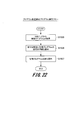
- FIG. 22 is a flowchart showing a procedure example of the program execution process of the program arrangement unit 15B.
- the program arrangement unit 15B-1B acquires the execution file of the target control program 7B-1 from the HMI node 3 and sets it in a state where it can be executed as the control program 7B-1 (S1525).
- the program arrangement unit 15B-1B notifies the command switching unit 84B in the I / O program 8B of the I / O node 2 of the IP address and port number of the control program 7B-1 (S1526), and the control program 7B- 1 is started to be executed (S1527).
- the program arrangement unit 15B-2B also operates in the same manner. After the end of step S1527, the process of this flowchart ends.
- FIG. 24 is a block diagram showing an example of a control command switching operation according to the second embodiment.
- the control programs 7B-1 and 7B-2 both transmit control commands 73B-1 and 73B-2 according to the processing flow of the judgment execution unit 70 shown in FIG. Since the contents of the control programs 7B-1 and 7B-2 are the same, exactly the same contents are described in the control contents column 73d of the control commands 73B-1 and 73B-2.
- the transmitted control commands 73B-1 and 73B-2 are received by the reception processing unit 81 of the I / O program 8B, and are processed by the command switching unit 84B according to the control command processing flow of FIG.
- the program arrangement units 15B-1B and 15B-2B of the configuration management programs 15B-1 and 15B-2 notify the command switching unit 84 of the I / O program 8B, and the control programs 7B-1, 7B- are displayed on the source list 87.
- the IP address and port number of 2 are added. As a result, a YES determination is made in step S844 of FIG. 9, and neither of the control commands 73B-1 and 73B-2 is discarded in step S846.
- FIG. 25 is a flowchart showing a procedure example of the monitoring process of the abnormality monitoring unit 15C.
- the abnormality monitoring unit 15C confirms the status of the control node to be monitored (S1530). For example, the abnormality monitoring unit 15C monitors a control node whose control node ID (for example, number) is one smaller than itself for an abnormality.
- the abnormality monitoring unit 15C of the control node having the control node ID “1” (minimum) monitors the control node having the maximum control node ID. That is, each control node 1B on the network 5 monitors each other in a string.
- the configuration management programs 15B-1 and 15B-2 monitor each other. Specific examples of the monitoring method include, but are not limited to, a method of confirming whether or not there is a response by a ping response, and a method of confirming whether or not the control node 1B to be monitored periodically transmits a control command.
- the abnormality monitoring unit 15C determines the presence / absence of an abnormality in the control node to be monitored (S1531), and if there is no abnormality in the control node (NO in S1531), the abnormality monitoring unit 15C continues the determination process for the presence / absence of an abnormality.
- the abnormality monitoring unit 15C detects an abnormality in the control node to be monitored (YES in S1531), it first determines whether or not the configuration management program 15 of the control node in which the abnormality has occurred is in the master state (S1532). If the corresponding configuration management program 15 is not in the master state (NO in S1532), the process proceeds to step S1534.
- the configuration management program 15 of the control node in which the abnormality has occurred is in the master state.
- 15B-2 is set as the master (S1533).
- the abnormality monitoring unit 15C notifies the abnormality monitoring unit 15C of the configuration management program 15 in the master state and the HMI program 9B of information on the occurrence of an abnormality, that is, the control node in which the abnormality has occurred (S1534).
- the abnormality monitoring unit 15B-2C in the slave state detects an abnormality in the control node 1B-1 in the master state, sets the configuration management program 15B-2 in the master state, and notifies itself of the occurrence of the abnormality.
- the abnormality monitoring unit 15C shifts to step S1530 after the process of step S1534.
- FIG. 26 shows an example of a control node abnormality warning screen.
- the HMI program 9B receives the notification of the occurrence of the abnormality of the control node, and by displaying the control node abnormality warning screen 92 shown in FIG. 26, notifies the administrator 36 of the control system 100B of the abnormality of the control node.
- the message “Control node [1] stopped!” Is displayed.
- the abnormality monitoring unit 15C excludes the information of the control node 1B-1 in which the abnormality has occurred from the control node management table 15G (S1536). Then, the abnormality monitoring unit 15C starts the program arrangement flow shown in FIG. 21 by the program arrangement unit 15B (S1537). If a control node that can be executed at this point exists on the network 5, the execution of the control program 7B is started by the program arrangement flow, and the redundant state is restored.
- the configuration management program 15B-3 starts execution on the control node 1B-3, and the configuration management program 15B-3 becomes a slave state according to the start flow (FIG. 16) of the master selection unit 15B-3A. Then, in step S1505 of FIG. 16, the master selection unit 15B-3A notifies the master selection unit 15B-2A that the control node 1B-3 has become available in the slave state.
- the control node management flow shown in FIG. 17 is started in the master selection unit 15B-2A of the control node 1B-2 (S1507). Then, the master selection unit 15B-2A adds the information of the control node 1B-3 to the control node management table 15B-2G (S1508), and the program placement flow is started (S1509). The newly connected control node 1B-3 is added as a slave. Then, in the program arrangement flow, the control program 7B is started to be executed on the control node 1B-3, and the control program 7B is restored to the redundant state again.
- control programs 7B-1, 7B-2 and 7B-3 in this embodiment do not need to manage the states of other control programs. Since the program that generates the control command 73 may be created as in the case of executing the control program without redundancy, the development of the control program is relatively easy.
- control command to be executed is selected by the command switching unit 84B from the control commands 73B-1 and 73B-2, but the present invention is not limited to this example.
- the control nodes 1B-4 and 1B-5 may be provided with the regular monitoring programs 16B-4 and 16B-5, respectively.
- the regular monitoring program 16B-5 when the control node 1B-4 transmits the control command 73B-4, the control command 73B-5 generated by the control program 7B-5 of the control node 1B-5 Is destroyed. Further, the regular monitoring program 16B-5 determines that the control node 1B-4 has failed if the control command 73B-4 is not transmitted even after a certain period of time has elapsed, and thereafter, the regular monitoring program 73B-5 is used as the regular monitoring program. It may be transmitted from 16B-5 to I / O node 2. If there is no other control node running the same control program 7B on the same network 5, the regular monitoring program does nothing.
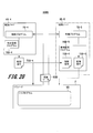
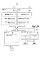
- FIG. 29 is a block diagram showing an example in which a plurality of control programs are operated on one control node according to a second modification of the second embodiment.
- one type of control program is executed on one control node, but a plurality of control programs may be operated on one control node.
- the I / O program (X) is stored as the I / O program 8B in the I / O node 2 (I / O node (1)) that controls the device (1), and the device.
- the I / O program (Y) is stored as the I / O program 8B in the I / O node 2B-1 (I / O node (2)) that controls (2).
- two control programs (X) 7B-6, 7B-9 and control programs (Y) 7B-7, 7B-8 for controlling the two I / O nodes 2 and 2B-1 are used. Arrange appropriately on the control nodes 1B-6 and 1B-7. Note that each of the I / O nodes 2 and 2B-1 may be able to control the devices (1) and (2).
- control program (X) 7B-6, the control program (Y) 7B-8, and the configuration management program 15B-6 are arranged in the control node 1B-6. Further, the control program (Y) 7B-7, the control program (X) 7B-9, and the configuration management program 15B-7 are arranged on the control node 1B-7. With such a configuration, control is continued even if either of the control nodes 1B-6 and 1B-7 fails, and the number of control nodes may be the same as that of the I / O nodes.
- the command switching unit 84B selects the first-come-first-served control command from the control commands 73B-1 and 73B-2, and executes the corresponding control command to perform only redundancy. ..
- a configuration in which a plurality of control programs are operated on one control node can be used for improving reliability.
- control system is configured to execute three or more of the same control programs on the same network 5. Then, in this control system, when all the contents of the control commands received at the same timing and transmitted by each control program do not match, the command switching unit 84B performs the first-come-first-served control among the many control commands whose control contents match. The command is passed to the control command execution unit 80.
- control system control node in the above example
- a control system capable of making resources (computer, software) redundant can be realized. Therefore, the availability of the control system is improved.
- the I / O program (I / O program 8B) should be executed from a plurality of control commands received from the plurality of control programs.
- a command switching unit (command switching unit 84B) for selecting a control command is provided, and a control program is executed on at least two control nodes (control nodes 1B-1 to 1B-3).
- the command switching unit is configured to send only the first-come-first-served control command from the control node to the control command execution unit (control command execution unit 80).
- the I / O program (I / O program 8B) is a control command to be executed from a plurality of control commands received from the plurality of control programs.
- a command switching unit (command switching unit 84B) for selecting is provided, and a control program is executed on at least three control nodes (control nodes 1B-1 to 1B-3).
- the command switching unit compares the control contents of the control commands received at the same timing, and when the control contents of different control contents are included, the control command is executed by selecting the control command having a large number of matching control contents. It is configured to be sent to a unit (control command execution unit 80).
- each control node includes a configuration management program (configuration management program 15).
- the configuration management program is Select a control node that operates in the master state from multiple control nodes, set its own control node to the slave state, and if there is no control node in the master state, set its own control node to the master state and set itself.
- Master selection unit master selection unit 15A
- An information synchronization unit (table synchronization unit 15E) that synchronizes the information of each control node in the control node in the master state and the control node in the slave state with the control node management table (control node management table 15G) provided in each control node.
- a program registration unit (program registration unit 15D) that receives control program information and redundancy configuration setting information specified in the user interface, and When a redundant configuration is requested, a program layout unit (program layout unit 15B) that refers to the control node management table to determine and execute two or more control nodes that execute the control program in the redundant configuration, and It has an abnormality monitoring unit (abnormality monitoring unit 15C) that monitors the control node and detects an abnormality. Then, in the master state configuration management program, when the abnormality monitoring unit receives the notification of the abnormality of the slave state control node, the information synchronization unit excludes the abnormal control node from the control node management table. However, the program placement unit is configured to select another control node that can be executed from the control node management table and execute the control program.
- control system 100B when there is no other control node that can be executed in the control node management table (control node management table 15G), a new control node (control system 100B) is used on the network.
- the master selection unit master selection unit 15A
- the program placement unit program placement
- Part 15B) is configured to determine the control node added to the control node management table as the control node that executes the control program in the redundant configuration.
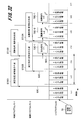
- FIG. 30 shows an example of execution timing of the control program and the I / O program of the control system according to the first embodiment.
- the control program 7 and the I / O program 8 show their respective execution timings in chronological order.
- the I / O program 8 that received the control command 73 transmits the transmission data 83.
- the transmission data 83 is received by the control program 7, and the control program 7 generates a control command 73 (S7101).
- FIG. 31 is a block diagram showing an example of the overall configuration of the control system according to the third embodiment.
- the control system 100C is configured as shown in FIG.
- the two control nodes 1B used in the second embodiment are set as control nodes 1C-1 and 1C-2, respectively, and the same control program 7 is executed.
- Each control program 7 is referred to as control programs 7C-1 and 7C-2.
- the control program 7C-1 and the configuration management program 15C-1 are arranged on the control node 1C-1
- the control program 7C-2 and the configuration management program 15C-2 are arranged on the control node 1C-2.
- the I / O node 2 executes the I / O program 8C.
- FIG. 32 shows an example of execution timing of the control program and the I / O program of the control system according to the third embodiment.
- the delay time can be shortened by adding 3 or 4 control nodes 1B according to the desired delay time.
- this embodiment is less costly than replacing it with a high-performance computer, and enables efficient investment.
- the I / O program 8C is a partial function of the I / O program 8 with additional changes. As shown in FIG. 31, the transmission processing unit 82C, the command switching unit 84 (not shown), and the source list 87C. (See FIG. 35) and has a scale-out configuration table 89 (see FIG. 36). Further, the HMI program 9C used in this configuration has a scale-out configuration setting screen 93.
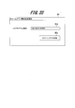
- the administrator 36 of the control system 100C first operates the control program 7C in a redundant configuration by the method shown in the second embodiment. Next, the administrator 36 uses the scale-out configuration setting screen 93 to send a signal to the transmission processing unit 82C of the I / O program 8C to adopt the scale-out configuration.
- a specific example of the scale-out configuration setting screen 93 is shown in FIG. 33.
- FIG. 34 is a flowchart showing a procedure example of the scale-out configuration start processing of the transmission processing unit 82C.
- the transmission processing unit 82C receives the scale-out start signal from the HMI program 9C (S8201), the transmission processing unit 82C starts the scale-out configuration start flow shown in FIG. 34.
- the transmission processing unit 82C refers to the source list 87C shown in FIG. 35 (S8202).
- FIG. 35 shows an example of the structure of the source list 87C.
- the source list 87C includes at least a source column 87a and an order column 87b.
- the source column 87a stores an IP address and a port number that specify a control program (for example, control command 73C1, 73C2) that generates a control command (for example, control command 73C1, 73C2).
- the order column 87b stores the execution order of a plurality of control programs designated by the control program.
- the control command 73 includes information on the source and order for specifying the control program, and the command switching unit 84 can create the source list 87C using the information.
- the transmission processing unit 82C determines the order in which the transmission data 83C is transmitted to the control program based on the contents of the source list 87C (S8203), and sets the scale-out configuration table 89 (S8204). After the end of step S8204, the process of this flowchart ends.
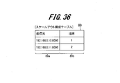
- FIG. 36 shows an example of the structure of the scale-out configuration table 89.
- the scale-out configuration table 89 includes at least a source column 89a and an order column 89b, similar to the source list 87C.
- the information in each column of the scale-out configuration table 89 is obtained from the source list 87C.
- the source column 89a stores an IP address and a port number that specify a control program (for example, control command 73C1, 73C2) that generates a control command (for example, control command 73C1, 73C2).
- the order column 89b stores the execution order of the plurality of control programs. In the order column 89b, numerical values are set in order from 1, which defines the order in which the transmission data 83C is transmitted.
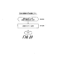
- FIG. 37 is a flowchart showing a procedure example of the transmission process of the transmission processing unit 82C.
- the transmission processing unit 82C receives the transmission data 83C from the control command execution unit 80 (S8205), and starts the transmission processing flow shown in FIG. 37.
- the transmission processing unit 82C confirms whether or not the scale-out configuration table 89 exists (S8206).
- the transmission processing unit 82C determines the transmission destination (destination control program) according to the order of the order field 89b, and transmits the transmission data (S8207). ). That is, the transmission processing unit 82C transmits the transmission data 83C to the control program 7C-1 in the order “1” in the scale-out configuration table 89, for example.
- the transmission data 83C is transmitted to the control program 7C-2 in the order "2".
- the transmission data is transmitted again from the order “1”.
- the transmission processing unit 82C is addressed to all the control programs on the network 5 as in the first embodiment or the second embodiment.
- the transmission data is transmitted (S8208). After the processing of step S8207 or S8208, the processing of this flowchart ends.
- control node 1 Since the control node 1 executes the control program 7 on the general-purpose OS 14, the maximum time required for processing cannot be guaranteed. Therefore, in practice, it is necessary to configure the control system using a number of control nodes 1 having a margin larger than the minimum required number.
- control system 100C at least processes the result processed by the I / O program (I / O program 8C) of the I / O node (I / O node 2).
- the two control nodes receive in order, and in each control node, the judgment execution unit (for example, the judgment execution unit 70) of the control program (control programs 7C-1, 7C-2) ) Is configured to generate a control command based on the result of the received process and sequentially transmit the control command to the I / O node.
- a control system capable of scale-out (dispersion of calculation processing) can be realized. Therefore, the performance of the control system can be improved.
- FIG. 38 is a block diagram showing an example of the overall configuration of the control system according to the fourth embodiment.
- the control system 100D of the present embodiment uses two I / O nodes 2 as I / O nodes 2D-1,2D-2.
- the I / O node 2D-1 is used as a regular system, and the I / O node 2D-2 is added as a standby system.
- the I / O node 2D-1 controls the device 4
- the I / O node 2D-2 controls the device 4 instead.
- the I / O node 2D-1 is connected to the device 4 by the cable 6 as in the first embodiment.
- the I / O node 2D-2 is also connected to the device 4 by using the cable 6D-2.
- the acquisition of information from the sensor 40 of the device 4 and the operation of the actuator 41 can be performed by the I / O node 2D-1 and the I / O node. It is configured so that both 2D-2 can be performed at the same time.
- the I / O programs 8D-1 and 8D-2 operating on the I / O nodes 2D-1 and 2D-2 include periodic synchronization units 88D-1 and 88D-2, respectively.
- the cycle synchronization unit 88D-1 operates as a server, and distributes the time information of the clock used as the reference of the control cycle by the control command execution unit 80D-1 via the network 5.
- the periodic synchronization unit 88D-2 operates as a client, and adjusts the clock of the control command execution unit 80D-2 based on the time received from the periodic synchronization unit 88D-1 to match the timing of the control cycle.
- the protocols specified in IEEE 1588 and IEEE 802.1AS can be used to realize the periodic synchronization units 88D-1 and 88D-2, but if the timing can be matched with the accuracy required for the control of the device 4, this can be used. Not limited to. Further, the periodic synchronization unit 88D-2 may determine that the I / O node 2D-1 is abnormal because the time cannot be received from the periodic synchronization unit 88D-1.
- the control program 7D generates the control command 73D and transmits the control command 73D to the I / O programs 8D-1 and 8D-2. Both the I / O programs 8D-1 and 8D-2 process the control command 73D in the same manner. Since the I / O programs 8D-1 and 8D-2 have the same control cycle and process the same control command 73D, the same input processing and output processing are performed on the device 4 at the same timing. When an abnormality occurs in the I / O node 2D-1, the control of the device 4 is continued by the I / O program 8D-2.
- the transmission processing unit 82D-2 of the I / O program 8D-2 receives a notification from the control command execution unit 80D-2 to transmit the transmission data 83D-2
- the transmission processing unit 82D-2 confirms with the periodic synchronization unit 88D-2 and I It is determined whether or not there is an abnormality in the / O node 2D-1.
- the transmission processing unit 82D-2 discards the transmission data 83D-2 without transmitting it, and when it is abnormal, the transmission data 83D-2 is sent to the control program 7D. To send. As a result, data is transmitted to the control program 7D from only one of the I / O programs 8D-1 and 8D-2.
- the I / O program 8D-1 is provided with a reception processing unit 81D-1, a transmission processing unit 82D-1, an input processing unit 85D-1, and an output processing unit 86D-1. Since the processing unit is the same as the corresponding processing unit of the first embodiment, detailed description thereof will be omitted. Further, although the I / O program 8D-2 is provided with a reception processing unit 81D-2, an input processing unit 85D-2, and an output processing unit 86D-2, detailed description thereof will be omitted in the same manner.
- the control cycle is synchronized in a string in order to detect the failure of the I / O node by the cycle synchronization unit. That is, one standby system I / O node that synchronizes the control cycle from the cycle synchronization unit of one regular system I / O node, and the cycle synchronization unit of this standby system I / O node synchronizes the control cycle. Connect to other standby I / O nodes in order.
- the I / O program 8D-2 controls the device 4 in parallel while the I / O program 8D-1 normally controls the device 4.
- the output processing unit 86D-2 in the I / O program 8D-2 is disabled so that all the instructions from the control command execution unit 80D-2 are ignored, and the periodic synchronization unit 88D-2 is the I / O node 2D.
- the output processing unit 86D-2 may be enabled so that the output processing for the device 4 is performed. In this case, it is possible to deal with the case where the actuator 41 of the device 4 cannot receive a plurality of signals for control.
- the configuration of this embodiment is used for the redundancy of the I / O node, it can also be used as a scale-out configuration in which the control processing is distributed.
- the configuration of this embodiment is used as a scale-out configuration.
- FIG. 39 shows an example of the execution timing of each I / O program when one I / O node is used and when two I / O nodes (regular, standby) according to the fourth embodiment are used. Is shown.
- FIG. 39 shows a configuration using one I / O node (one I / O program 8) and a state of processing in two I / O programs when scale-out is performed using this configuration.
- the present embodiment can be used in order to shorten the substantial control cycle seen from the device by executing the same process at different timings of the control cycle.
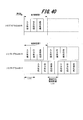
- FIG. 40 shows the respective I / O when one I / O node is used and when the control cycle is shifted by using the two I / O nodes (normal and standby) according to the fourth embodiment.
- An example of program execution timing is shown.
- FIG. 40 shows a configuration using one I / O node (one I / O program 8) and two I / O when scale-out is performed by shifting the control cycle using this configuration.
- This is an example showing the state of processing in the program in chronological order.
- the start timing of the control cycle of the I / O program 8D-4 is delayed by 1 / 2T with respect to the I / O program 8D-3, and the control commands T for both the I / O programs 8D-3 and 8D-4.
- Both I / O programs have a control cycle T, but when viewed from the device 4 to be controlled, the same processing is performed every 1 / 2T, so control equivalent to that executed in the control cycle 1 / 2T is realized. can.
- control program 7D exists on the network 5, but a plurality of control programs 7D may actually exist. Further, the configuration shown in the first to third embodiments can be used in combination with the present embodiment.
- control system 100D can acquire and operate information on at least two I / O nodes (I / O nodes 2D-1, 2D-2), respectively. It is connected to the device to be controlled so that it can be operated at the same time, and one of the plurality of I / O nodes is operated as a regular system and the other I / O nodes are operated as a standby system.
- control system 100D at least two I / O nodes (I / O nodes 2D-1, 2D-2) are in a state in which their control cycles are synchronized. Connect to the same controlled device with.
- the judgment execution unit for example, the judgment execution unit 70 of the control program (control program 7D) controls the I / O programs (I / O programs 8D-1, 8D-2) at each I / O node.
- a control command with the same control content is generated by shifting the start timing of the command execution unit (control command execution unit 80D-1, 80D-2) for each I / O program within the control cycle, and the control target is controlled.
- a control command is transmitted to two or more I / O nodes connected to the device, and the control command execution unit of the I / O program executes the control command at the set start timing at each I / O node. It is configured.
- each of the above-described embodiments describes the configuration of the control system in detail and concretely in order to explain the present invention in an easy-to-understand manner, and is not necessarily limited to the one including all the components described.
- each of the above configurations, functions, processing units, etc. may be realized by hardware, for example, by designing a part or all of them with an integrated circuit.
- FPGA Field Programmable Gate Array
- ASIC Application Specific Integrated Circuit
- a plurality of processes may be executed in parallel or the processing order may be changed as long as the processing results are not affected.
- control lines and information lines are shown as necessary for explanation, and not all the control lines and information lines are necessarily shown in the product. In practice, it can be considered that almost all components are interconnected.
- Real-time OS 25 ... I / O interface , 30 ... CPU, 31 ... storage device, 32 ... network interface, 33 ... memory, 34 ... general-purpose OS, 35 ... user interface, 40 ... sensor, 41 ... actuator, 70 ... judgment execution unit, 71 ... reception processing unit, 72 ... Transmission processing unit, 73 ... Control command, 80 ... Control command execution unit, 81 ... Reception processing unit, 82 ... Transmission processing unit, 83 ... Transmission data, 84 ... Command switching unit, 85 ... Input processing unit, 86 ... Output processing Unit, 87 ... Source list, 88 ... Time synchronization unit, 89 ... Scale-out configuration table, 90 ... Switching signal transmission screen, 91 ... Control program registration screen, 92 ... Control node error warning screen, 93 ... Scale-out configuration setting screen , 100, 100B, 100C, 100D ... Control system
Landscapes
- Engineering & Computer Science (AREA)
- Physics & Mathematics (AREA)
- General Physics & Mathematics (AREA)
- Theoretical Computer Science (AREA)
- Automation & Control Theory (AREA)
- General Engineering & Computer Science (AREA)
- Programmable Controllers (AREA)
Abstract
1台以上の制御ノードと、1台以上の機器に接続され、制御ノードと通信可能な1台以上のI/Oノードと、から構成された制御システムにおいて、制御ノードは、少なくとも1個の制御プログラムを第1のOS上で実行し、I/Oノードは、少なくとも1個のI/Oプログラムをより定時性の高い第2のOS上で実行する。制御プログラムは、機器に関して予め設定された状態制御に基づいて制御指令を生成してI/Oノードに送信する。I/Oプログラムは、制御ノードから受信した制御指令を記憶部に記憶し、その記憶部に記憶された制御指令に従って機器に関する処理を実行する。
Description
本発明は、例えばファクトリーオートメーション(FA)やプロセスオートメーション(PA)の分野において、コンピュータを用いて制御を行う制御システムに関する。
一般にファクトリー・オートメーション(FA)やプロセス・オートメーション(PA)の分野では、工場などにおける製造工程や化学製品などの生産工程などに、コンピュータを用いた制御システムが導入される。制御システムは、プログラマブル・ロジック・コントローラ(PLC)などのコンピュータがコンピュータプログラムを実行することで制御を行う。
こうした制御システムの処理概要を説明する。コンピュータは、温度や圧力、回転数など制御に必要となる情報をセンサから取得する。コンピュータは、その情報に基づき、アクチュエータやモータなどを操作する。制御する内容はプログラムに定義され、コンピュータはプログラムを実行することで制御を行う。制御は適切なタイミングで実施される必要があり、適切なタイミングに制御できる性能や度合いを「定時性」という。
例えば、特許文献1には、シーケンシャルな制御ロジック(各種判断等)をPLCで実行し、複雑な演算処理(収束演算等の数値演算)を汎用OS上で実行し、処理すべき機能を振り分けるようにしたプラント制御システムが開示されている。
近年、自動車の自動運転に代表される人工知能技術の発展がある。人工知能技術の分野では、ディープラーニングの推論処理などの複雑な計算処理による高度な判断処理を制御システムに導入することが求められている。この判断処理の実現には以下のような問題がある。
(問題点1)
制御システムは、定時性高く制御を行う必要がある。PLCなどは定時性の高いリアルタイムオペレーティングシステム(OS)上でプログラムを実行することで定時性を確保している。リアルタイムOSは、時間的な制約がある処理を実行するための機能や特性を備える。一方、推論処理のように複雑な処理を行うプログラムは、汎用OS上での実行を前提に開発されている場合があり、リアルタイムOS上で実行することは困難である。
制御システムは、定時性高く制御を行う必要がある。PLCなどは定時性の高いリアルタイムオペレーティングシステム(OS)上でプログラムを実行することで定時性を確保している。リアルタイムOSは、時間的な制約がある処理を実行するための機能や特性を備える。一方、推論処理のように複雑な処理を行うプログラムは、汎用OS上での実行を前提に開発されている場合があり、リアルタイムOS上で実行することは困難である。
(問題点2)
工場の製造工程などでは、設備を数ヶ月から数年にわたり稼動し続ける場合があり、制御システムを停止させないことを前提としている。一方で、制御システムに新たな機能を追加するためには、一時的に制御システムを停止する必要がある。また、老朽化により制御システムを構成するソフトウェア又はハードウェアの交換が必要となる場合であっても、頻繁に停止することはできず、交換が先送りにされる場合がある。
工場の製造工程などでは、設備を数ヶ月から数年にわたり稼動し続ける場合があり、制御システムを停止させないことを前提としている。一方で、制御システムに新たな機能を追加するためには、一時的に制御システムを停止する必要がある。また、老朽化により制御システムを構成するソフトウェア又はハードウェアの交換が必要となる場合であっても、頻繁に停止することはできず、交換が先送りにされる場合がある。
前述の通り、制御システムは動作し続けることが求められる。そのため2台以上のコンピュータを用いて制御システムを冗長化構成とし、1台のコンピュータが故障しても制御システムの動作を継続することが行われる。この際、各コンピュータが実行するプログラムは、他のコンピュータのプログラムとタイミングや情報を同期し、故障時にも定時性を損なわない性能を備える必要があり、難易度が高い。
このような高い定時性が要求される制御システムを稼動させたまま、制御システムのプログラムやコンピュータ等を変更する技術については、特許文献1に開示されていない。
本発明は、上記の状況に鑑みてなされたものであり、本発明は、定時性を保ちながら、制御システムを停止させることなく、制御システムで用いるリソースの変更を可能にすることを目的とする。
上記課題を解決するために、本発明の一態様の制御システムは、少なくとも1台の制御ノードと、1台以上の制御対象機器に接続され、ネットワークを介して制御ノードと通信可能な少なくとも1台のI/Oノードと、から構成される。
上記制御ノードは、第1のオペレーティングシステムと、少なくとも1個の制御プログラムを第1のオペレーティングシステム上で実行する第1のプロセッサと、を備える。
上記I/Oノードは、第1のオペレーティングシステムよりも定時性の高い第2のオペレーティングシステムと、少なくとも1個のI/Oプログラムを第2のオペレーティングシステム上で実行する第2のプロセッサと、を備える。
上記制御ノードの制御プログラムは、制御対象機器に関して予め設定された状態制御に基づいて制御指令を生成し、当該制御指令をI/Oノードに送信する判断実行部を有する。
上記I/OノードのI/Oプログラムは、制御ノードから受信した制御指令を記憶部に記憶し、その記憶部に記憶された制御指令に従って制御対象機器に関する処理を実行する制御指令実行部を有する。
上記制御ノードは、第1のオペレーティングシステムと、少なくとも1個の制御プログラムを第1のオペレーティングシステム上で実行する第1のプロセッサと、を備える。
上記I/Oノードは、第1のオペレーティングシステムよりも定時性の高い第2のオペレーティングシステムと、少なくとも1個のI/Oプログラムを第2のオペレーティングシステム上で実行する第2のプロセッサと、を備える。
上記制御ノードの制御プログラムは、制御対象機器に関して予め設定された状態制御に基づいて制御指令を生成し、当該制御指令をI/Oノードに送信する判断実行部を有する。
上記I/OノードのI/Oプログラムは、制御ノードから受信した制御指令を記憶部に記憶し、その記憶部に記憶された制御指令に従って制御対象機器に関する処理を実行する制御指令実行部を有する。
本発明の少なくとも一態様によれば、定時性を保ちながら、制御システムを停止させることなく、制御システムで用いるリソースの変更が可能になる。
上記した以外の課題、構成及び効果は、以下の実施形態の説明により明らかにされる。
上記した以外の課題、構成及び効果は、以下の実施形態の説明により明らかにされる。
以下、本発明を実施するための形態の例について、添付図面を参照して説明する。本明細書及び添付図面において実質的に同一の機能又は構成を有する構成要素については、同一の符号を付して重複する説明を省略する。
<1.第1の実施形態>
[制御システムの全体構成]
まず、本発明の第1の実施形態に係る制御システムの構成例について説明する。
図1は、第1の実施形態に係る制御システムの全体構成の例を示すブロック図である。
[制御システムの全体構成]
まず、本発明の第1の実施形態に係る制御システムの構成例について説明する。
図1は、第1の実施形態に係る制御システムの全体構成の例を示すブロック図である。
図1に示す制御システム100は、制御ノード1、I/Oノード2、HMIノード3、制御対象の機器4、及び、各ノードを相互に通信可能に接続したネットワーク5を含んで構成される。制御システム100において、制御ノード1は少なくとも1台以上であり、I/Oノード2も少なくとも1台以上である。
機器4は、例えば工場の生産設備として用いられる機器であり、機器4に所望の動作をさせることが制御システム100の目標である。機器4は、センサ40とアクチュエータ41を持つ。図1ではセンサ40とアクチュエータ41をそれぞれ1つのみ示しているが、実際には、複数個ある場合や、センサ40又はアクチュエータ41のどちらか一方のみを持つ場合もある。
センサ40は、機器4やその周辺の環境の状態を把握するための装置である。アクチュエータ41は、機器4に実際の動作を行わせたり、動作を変更させたりするための装置である。センサ40の例としては、温度計、流量計、電圧計、スイッチ、ビデオカメラ、カウンタなどが挙げられる。アクチュエータ41の例としては、モータ、シリンダー、電磁石、リレー、LED、ランプ、ブザーなどが挙げられる。当然のことながら、センサ40、アクチュエータ41とも上記に示す例に限定されない。
制御ノード1は、CPU(Central Processing Unit)10、記憶装置11(記憶部の例)、ネットワークインタフェース12、及びメモリ13から構成されるコンピュータである。CPU10は、第1のプロセッサの例である。CPU10の代わりに、MPU(Microprocessor)などの他のプロセッサを用いてもよい。メモリ13は、半導体メモリなどを用いた主記憶装置である。記憶装置11は、不揮発性の記憶装置であり、記憶装置11として、例えばハードディスクや半導体メモリなどが用いられる。
I/Oノード2も同様に、CPU20(第1のプロセッサ)、記憶装置21(記憶部の例)、ネットワークインタフェース22、及びメモリ23から構成されるコンピュータである。また、HMIノード(Human Machine Interface)3は、CPU30、記憶装置31、ネットワークインタフェース32、及びメモリ33から構成されるコンピュータである。
制御ノード1において、CPU10は、記憶装置11からメモリ13上に汎用OS14(第1のオペレーティングシステム)を読み込んで実行する。また、CPU10は、汎用OS14上で、1個以上の制御プログラム7を実行する。記憶装置11は、後述する各種テーブル等を記憶する。
I/Oノード2において、CPU20は、記憶装置21からメモリ23上にリアルタイムOS24(第2のオペレーティングシステム)を読み込んで実行する。また、CPU20は、リアルタイムOS24上で、I/Oプログラム8を実行する。記憶装置21は、後述する送信元リスト87等を記憶する。また、I/Oノード2はさらにI/Oインタフェース25を持ち、ケーブル6により機器4と接続している。
I/Oインタフェース25と機器4との間を接続するケーブル6、及び、その間の通信方式の具体例としては、ねじ端子を介し機器4を直接配線する方法や、機器4の持つインタフェースを介し、機器4で規定のプロトコルにより通信する方法が想定される。本実施形態においては、レイテンシ(遅延)が小さく機器4のセンサ40及びアクチュエータ41と通信可能であればいかなる方式でも構わない。通信に用いる規格の具体例としては、USB(Universal Serial Bus)、RS-232、Ethernet(登録商標)が挙げられ、Bluetooth(登録商標)等による無線通信によっても実現可能である。
HMIノード3において、CPU30は、記憶装置31よりメモリ33上に汎用OS34を読み込んで実行する。またCPU30は、汎用OS34上でHMIプログラム9を実行する。また、HMIノード3は、ディスプレイ35Aやキーボード35Bなどのユーザインタフェース35を備える。
制御ノード1、I/Oノード2、及びHMIノード3は、それぞれのネットワークインタフェース12,22,及び32を通してネットワーク5に接続している。ネットワーク5の通信方式の具体例として、Ethernet(登録商標)、CAN(Controller Area Network)(登録商標)などが挙げられる。ネットワーク5を通し、制御プログラム7、I/Oプログラム8、及びHMIプログラム9は、1対1及び1対多の通信が可能なUDP over IPといったプロトコルを用いて相互に通信する。
制御ノード1とI/Oノード2は、それぞれのCPUが実行する制御プログラム7、I/Oプログラム8の処理によって機器4の制御を実現する。以下、図2を参照して、制御プログラム7とI/Oプログラム8の機能構成を説明する。
[制御プログラムとI/Oプログラムの論理構成]
図2は、制御システム100の制御プログラム7とI/Oプログラム8の論理構成の例を示すブロック図である。
制御プログラム7は、判断実行部70、受信処理部71、及び送信処理部72を持つ。制御プログラム7の各部の機能については後述する。
I/Oプログラム8は、制御指令実行部80、受信処理部81、送信処理部82、指令切替部84、入力処理部85、出力処理部86、及び送信元リスト87を持つ。入力処理部85は、センサ40から情報(検出結果)を取得し、出力処理部86はアクチュエータ41に制御信号を送ってアクチュエータ41を操作する。I/Oプログラム8の各部の機能については後述する。
図2は、制御システム100の制御プログラム7とI/Oプログラム8の論理構成の例を示すブロック図である。
制御プログラム7は、判断実行部70、受信処理部71、及び送信処理部72を持つ。制御プログラム7の各部の機能については後述する。
I/Oプログラム8は、制御指令実行部80、受信処理部81、送信処理部82、指令切替部84、入力処理部85、出力処理部86、及び送信元リスト87を持つ。入力処理部85は、センサ40から情報(検出結果)を取得し、出力処理部86はアクチュエータ41に制御信号を送ってアクチュエータ41を操作する。I/Oプログラム8の各部の機能については後述する。
HMIプログラム9は、制御システム100の管理者36が制御システム100の状態の設定や確認を行うための複数の画面を持つ。画面はGUI(Graphical User Interface)として実装され、ユーザインタフェース35を介して制御システム100の管理者36に操作される。図2では、HMIプログラム9が切替信号送信画面90により生成された切替信号を、I/Oプログラム8の指令切替部84に送信する様子が示されている。切替信号送信画面90については、後述する図11において詳述する。指令切替部84は、受け取った制御指令73の送信元情報を送信元リスト87に登録する。
制御指令73は、制御プログラム7の判断実行部70によって生成される電文であり、特定の条件において、どのような処理、動作を行うかという指示が記されている。例えば、平易な表現で記せば、制御指令73は「30ミリ秒ごとにセンサ40の電圧値を制御プログラム7に送信せよ」、「時刻Xのタイミングでアクチュエータ41をYミリ秒間動作させよ」、「センサ40の電圧値の移動平均を計算せよ」といった内容である。
制御プログラム7からI/Oプログラム8に送信される制御指令73は、I/Oプログラム8の受信処理部81で順次受信される。受信処理部81は、受信した制御指令73を、記憶装置21(記憶部)の指令記憶エリア211に順次記憶する。
送信データ83は、制御指令73に従い、I/Oプログラム8の制御指令実行部80が生成して、制御プログラム7の判断実行部70に送信する情報を記した電文である。例えば、送信データ83には、センサ40の電圧値や、制御指令実行部80が計算した結果の値などが含まれる。判断実行部70は、送信データ83の内容を受信することで機器4の状態など必要な情報を取得する。
図3は、制御指令73が持つ情報の例を示す図表である。
制御指令73は、送信元欄73a、宛先欄73b、生成日時欄73c、及び制御内容欄73dを備える。
送信元欄73aは、制御指令73を生成した制御プログラム7を特定するIPアドレスとポート番号を格納する。
宛先欄73bは、制御プログラムを実行すべきI/Oプログラム8を特定するIPアドレスとポート番号を格納する。
生成日時欄73cは、制御指令73が生成された日付と時刻を格納する。
制御内容欄73dは、制御指令73の制御の内容を格納する。
制御指令73は、送信元欄73a、宛先欄73b、生成日時欄73c、及び制御内容欄73dを備える。
送信元欄73aは、制御指令73を生成した制御プログラム7を特定するIPアドレスとポート番号を格納する。
宛先欄73bは、制御プログラムを実行すべきI/Oプログラム8を特定するIPアドレスとポート番号を格納する。
生成日時欄73cは、制御指令73が生成された日付と時刻を格納する。
制御内容欄73dは、制御指令73の制御の内容を格納する。
制御内容欄73dは、制御指令73ごとにその内容が異なるが、共通して指令ID欄73e、優先度欄73f、タイミング欄73g、及び最大時間欄73hを持つ。
指令ID欄73eは、制御指令73を一意に特定する指令IDを保持する。指令IDは判断実行部70により制御指令73生成時に付与される。
優先度欄73fは、制御指令73の優先度を保持する。優先度欄73fが空欄の場合には、優先度が最も低いことを示す。
タイミング欄73gは、制御内容欄73dに記載された処理を実行すべきタイミングを保持する。タイミングの内容は、一定の間隔で周期的に実行する場合、センサの状態などの条件を満たした場合、指定の時刻になった場合など様々な場合を指定できる。
最大時間欄73hは、一つの制御指令73の処理に許容できる最大時間(後述する図8)を保持する。最大時間欄73hが空欄の場合は、最大時間が設定されていないことを示す。
指令ID欄73eは、制御指令73を一意に特定する指令IDを保持する。指令IDは判断実行部70により制御指令73生成時に付与される。
優先度欄73fは、制御指令73の優先度を保持する。優先度欄73fが空欄の場合には、優先度が最も低いことを示す。
タイミング欄73gは、制御内容欄73dに記載された処理を実行すべきタイミングを保持する。タイミングの内容は、一定の間隔で周期的に実行する場合、センサの状態などの条件を満たした場合、指定の時刻になった場合など様々な場合を指定できる。
最大時間欄73hは、一つの制御指令73の処理に許容できる最大時間(後述する図8)を保持する。最大時間欄73hが空欄の場合は、最大時間が設定されていないことを示す。
制御内容欄73d(1)~73d(6)は、実施する処理ごとの制御内容の具体例を示している。
制御内容欄73d(1)は、入力処理、すなわちセンサ40からの情報取得を行う場合の例である。制御内容欄73d(1)は入力処理欄73iを備え、情報を取得する対象を保持する。
制御内容欄73d(2)は、計算処理、すなわちセンサ40の出力値の移動平均などの計算処理を行う場合の例である。制御内容欄73d(2)は計算処理欄73jを備え、計算処理の内容を保持する。
制御内容欄73d(3)は、送信処理、すなわち制御プログラム7に情報を送信する場合の例である。制御内容欄73d(3)は送信処理欄73kを備え、送信する対象を保持する。
制御内容欄73d(1)は、入力処理、すなわちセンサ40からの情報取得を行う場合の例である。制御内容欄73d(1)は入力処理欄73iを備え、情報を取得する対象を保持する。
制御内容欄73d(2)は、計算処理、すなわちセンサ40の出力値の移動平均などの計算処理を行う場合の例である。制御内容欄73d(2)は計算処理欄73jを備え、計算処理の内容を保持する。
制御内容欄73d(3)は、送信処理、すなわち制御プログラム7に情報を送信する場合の例である。制御内容欄73d(3)は送信処理欄73kを備え、送信する対象を保持する。
制御内容欄73d(4)は、出力処理、すなわちアクチュエータなどの操作を行う場合の例である。制御内容欄73d(4)は出力処理欄73lを備え、操作対象の指令IDと操作の内容を保持する。
制御内容欄73d(5)は、制御周期設定処理、すなわち後述する制御周期に関する設定を行う場合の例である。制御内容欄73d(5)は制御周期設定欄73mを備え、指定する制御周期や開始タイミングを保持する。
制御内容欄73d(6)は、中止処理、すなわち特定の制御指令73の実行を中止する場合の例である。制御内容欄73d(6)は中止処理欄73nを備え、中止対象の指令IDを保持する。
制御内容欄73d(5)は、制御周期設定処理、すなわち後述する制御周期に関する設定を行う場合の例である。制御内容欄73d(5)は制御周期設定欄73mを備え、指定する制御周期や開始タイミングを保持する。
制御内容欄73d(6)は、中止処理、すなわち特定の制御指令73の実行を中止する場合の例である。制御内容欄73d(6)は中止処理欄73nを備え、中止対象の指令IDを保持する。
図4は、送信データ83が持つ情報の例を示す図表である。
送信データ83は、送信元欄83a、送信日時欄83b、指令ID欄83c、及びデータ欄83dを備える。
送信元欄83aは、送信データ83を生成したI/Oプログラム8を特定するIPアドレスとポート番号を格納する。
送信日時欄83bは、送信データ83をI/Oプログラム8が送信した日付と時刻を格納する。
指令ID欄83cは、送信データ83がどの制御指令73の指示によって送信されたのかを特定する指令IDを格納する。
データ欄83dは、送信するデータの内容(例えば対象、値)を保持する。
送信データ83は、送信元欄83a、送信日時欄83b、指令ID欄83c、及びデータ欄83dを備える。
送信元欄83aは、送信データ83を生成したI/Oプログラム8を特定するIPアドレスとポート番号を格納する。
送信日時欄83bは、送信データ83をI/Oプログラム8が送信した日付と時刻を格納する。
指令ID欄83cは、送信データ83がどの制御指令73の指示によって送信されたのかを特定する指令IDを格納する。
データ欄83dは、送信するデータの内容(例えば対象、値)を保持する。
制御システム100は、制御ノード1の汎用OS14上で実行される制御プログラム7の判断実行部70(図2)が、機器4に関して予め設定された状態制御に基づいて制御指令73を生成する。言い換えると、判断実行部70は、センサ40等から得られる情報に基づいて機器4をどのような状態に変化させるか、又は、どのように変化させるかを複雑な演算などを伴う処理によって検討し、その検討結果を制御指令73としてI/Oノード2(I/Oプログラム8)に送信する。この機器4に関する制御内容の検討は、周知の技術を用いて行うものとし、ここでは詳細な説明は省略する。
機器4の操作などの実際の処理はI/Oノード2のリアルタイムOS24上で実行される。リアルタイムOS24上で、I/Oプログラム8の制御指令実行部80が制御指令を実行することにより、複雑な処理と定時性の高い処理の両立を可能にする。
[判断実行部の処理]
以下、図5を参照し、制御プログラム7の判断実行部70の処理内容を説明する。
図5は、判断実行部70による処理の手順例を示すフローチャートである。
まず、判断実行部70は、制御システム100としてI/Oプログラム8にどのタイミングでどのような処理を実行させるかを判断する(S701)。次いで、判断実行部70は、制御指令を生成する必要があるかどうかを判断し(S702)、制御指令を生成する必要がない場合(S702のNO)にはステップS705へ進む。次いで、判断実行部70は、制御指令の生成が必要な場合(S702のYES)には制御指令73を生成し(S703)、送信処理部72にI/Oプログラム8へ送信させる(S704)。
以下、図5を参照し、制御プログラム7の判断実行部70の処理内容を説明する。
図5は、判断実行部70による処理の手順例を示すフローチャートである。
まず、判断実行部70は、制御システム100としてI/Oプログラム8にどのタイミングでどのような処理を実行させるかを判断する(S701)。次いで、判断実行部70は、制御指令を生成する必要があるかどうかを判断し(S702)、制御指令を生成する必要がない場合(S702のNO)にはステップS705へ進む。次いで、判断実行部70は、制御指令の生成が必要な場合(S702のYES)には制御指令73を生成し(S703)、送信処理部72にI/Oプログラム8へ送信させる(S704)。
次いで、判断実行部70は、新しい送信データ83があれば受信処理部71より受け取る(S705)。判断実行部70は、受信処理部71が受信した送信データ83について、送信元欄83a(図4)により自身が制御しているI/Oプログラム8から送信されたものであることを確認し、送信データ83を処理して次回のステップS701における判断に用いる。
制御プログラム7は、ステップS701~S705の処理を常時実行しており、随時制御指令73をI/Oノード2(I/Oプログラム8)へ送信する。
I/Oプログラム8の受信処理部81は、ステップS704にて判断実行部70が送信した制御指令73を受信すると、指令切替部84に制御指令73を渡す。指令切替部84は、後述する方法により実行すべき制御指令73を選択し、該当する制御指令73を制御指令実行部80に渡す。
[制御指令実行部の制御指令受付処理]
図6は、制御指令実行部80の制御指令受付処理の手順例を示すフローチャートである。
制御指令実行部80は、指令切替部84から新しい制御指令73を受け取ると(S801)、制御指令受付フローを開始する。すなわち、制御指令実行部80は、後述する図7に示す周期処理フローに沿って制御指令73が実行されるよう設定する(S802)。ステップS802の終了後、本フローチャートの処理を終了する。
図6は、制御指令実行部80の制御指令受付処理の手順例を示すフローチャートである。
制御指令実行部80は、指令切替部84から新しい制御指令73を受け取ると(S801)、制御指令受付フローを開始する。すなわち、制御指令実行部80は、後述する図7に示す周期処理フローに沿って制御指令73が実行されるよう設定する(S802)。ステップS802の終了後、本フローチャートの処理を終了する。
[制御指令実行部の周期処理]
次に、I/Oプログラム8の制御指令実行部80が制御指令73を実行する手順について図7を参照して説明する。
図7は、制御指令実行部80の周期処理の手順例を示すフローチャートである。
次に、I/Oプログラム8の制御指令実行部80が制御指令73を実行する手順について図7を参照して説明する。
図7は、制御指令実行部80の周期処理の手順例を示すフローチャートである。
制御指令実行部80は、一定の時間の周期内で制御指令の実行を行う。この時間の周期を「制御周期」と呼ぶ。制御周期は、制御指令73によって設定される。まず、制御指令実行部80は、現在時刻が制御周期の開始時刻になったかどうかを判定し(S803)、まだ制御周期の開始時刻になっていない場合には(S803のNO)、制御周期の開始時刻の監視を継続する。
次いで、制御指令実行部80は、制御周期を開始すべき時刻になったと判定した場合(S803のYES)、制御周期用の打ち切りタイマの動作を開始する(S804)。制御指令実行部80は、打ち切りタイマの計測時間から制御周期に相当する時間の経過を判断する。制御指令実行部80は、指定された制御周期に相当する時間を超えても制御指令73に基づく処理が完了しない場合、その間に実行されている制御指令73の実行を打ち切る(中止)。
次いで、制御指令実行部80は、制御指令73を優先度の高い順に実行するループを開始する(S805)。次いで、制御指令実行部80は、現在の状態が制御指令73の実行タイミングの条件を満たしているかを判定し(S806)、実行タイミングの条件を満たしていない場合には(S806のNO)、ステップS816へ進む。
次いで、制御指令実行部80は、最大時間用の打ち切りタイマの動作を開始する(S807)。制御指令実行部80は、指定された最大時間を超えても1つの制御指令73に基づく処理が完了しない場合、そのときに実行されている制御指令73の実行を打ち切る(中止)。制御指令実行部80は、最大時間欄73hが空欄の場合には打ち切りタイマを開始しない。次いで、制御指令実行部80は、制御指令73の処理種別(制御内容)を判断し(S808)、処理種別に沿ってステップS809~S814の処理を実行する。
ステップS809は、入力処理のためのステップである。制御指令実行部80は、センサ40の情報を取得し、取得した情報を他ステップが利用できるようメモリ23の変数に格納する。
ステップS810は、計算処理のためのステップである。制御指令実行部80は、計算処理を実行し、その結果を他ステップが利用できるようメモリ23の変数に格納する。 ステップS811は、送信処理のためのステップである。制御指令実行部80は、送信すべき情報を含む送信データ83を生成し、送信処理部82によりネットワーク5上の全ての制御プログラム7に送信させる。
ステップS812は、出力処理のためのステップである。制御指令実行部80は、出力処理部86を介して制御対象の機器4のアクチュエータ41を操作する。
ステップS813は、設定処理のためのステップである。制御指令実行部80は、制御周期の変更を行う。
ステップS814は、中止処理のためのステップである。制御指令実行部80は、指令IDで指定された制御指令73を実行されないように削除する。
ステップS810は、計算処理のためのステップである。制御指令実行部80は、計算処理を実行し、その結果を他ステップが利用できるようメモリ23の変数に格納する。 ステップS811は、送信処理のためのステップである。制御指令実行部80は、送信すべき情報を含む送信データ83を生成し、送信処理部82によりネットワーク5上の全ての制御プログラム7に送信させる。
ステップS812は、出力処理のためのステップである。制御指令実行部80は、出力処理部86を介して制御対象の機器4のアクチュエータ41を操作する。
ステップS813は、設定処理のためのステップである。制御指令実行部80は、制御周期の変更を行う。
ステップS814は、中止処理のためのステップである。制御指令実行部80は、指令IDで指定された制御指令73を実行されないように削除する。
次いで、制御指令実行部80は、最大時間用の打ち切りタイマを終了する(S815)。この間に、1つの制御指令73の実行が終了する。制御指令実行部80は、全ての制御指令73についてステップS806~S815の処理を繰り返し実行した後、制御指令73を優先度の高い順に実行するループを終了する(S816)。
次いで、制御指令実行部80は、制御周期用の打ち切りタイマを終了する(S817)。そして、制御指令実行部80は、ステップS803に戻り、ステップS803~S817の処理を繰り返し実行する。
図8に、制御指令実行部80における制御指令73の実行タイミングの例を示す。
図8では、制御指令実行部80の周期処理フロー(図7)における制御指令73の実行の様子を時間軸で表している。最大時間用の打ち切りタイマにより、各制御指令73(制御指令1~4…)は最大時間を超えて実行されない。また、制御周期用の打ち切りタイマにより、各制御指令73(制御指令1~4…)が制御周期を超えて実行され続けることもない。そのため、制御指令実行部80は、制御指令73を定時性高く実行することができる。
図8では、制御指令実行部80の周期処理フロー(図7)における制御指令73の実行の様子を時間軸で表している。最大時間用の打ち切りタイマにより、各制御指令73(制御指令1~4…)は最大時間を超えて実行されない。また、制御周期用の打ち切りタイマにより、各制御指令73(制御指令1~4…)が制御周期を超えて実行され続けることもない。そのため、制御指令実行部80は、制御指令73を定時性高く実行することができる。
制御指令実行部80は周期処理フローを常時実行し、制御周期毎に優先度順に全ての制御指令73を順次実行するようにしたが、制御指令73を定時性高く実行できる方法であればこれに限らない。リアルタイムOS24の機能により、制御指令73の実行タイミングの条件が満たされると、割り込み処理によって制御指令73の制御内容が実行されるようにしてもよい。また、実行中の制御指令73をコンテキストスイッチによって中断し、より優先度の高い制御指令73が実行されるようにしてもよい。コンテキストスイッチは、CPUの状態を保存したり復元したりする機能である。また、I/Oノード2のCPU20が複数のコアを持つ場合には、制御指令の処理を並列に実行してもよい。
また、制御プログラム7とI/Oプログラム8を特定する情報としてIPアドレスとポート番号を用いているが、ネットワーク5上のプロトコルが用いるもので、ネットワーク5上のプログラムを一意に特定できる情報ならばこれに限らない。以降の説明においても同様である。
[制御プログラムを変更する手順]
再び図2を参照して、本実施形態に係る制御システム100において、制御プログラム7を変更する手順を説明する。
制御システム100の管理者36は、制御ノード1の制御プログラムを変更するために、変更前の制御プログラム7を動作させた状態で、制御ノード1上で変更後の制御プログラム7A-1を動作させる。そして、I/Oプログラム8の制御指令実行部80が、制御プログラム7A-1の判断実行部70A-1が生成した制御指令73A-1を処理するように切り替え、変更前の制御プログラム7を停止させる。
再び図2を参照して、本実施形態に係る制御システム100において、制御プログラム7を変更する手順を説明する。
制御システム100の管理者36は、制御ノード1の制御プログラムを変更するために、変更前の制御プログラム7を動作させた状態で、制御ノード1上で変更後の制御プログラム7A-1を動作させる。そして、I/Oプログラム8の制御指令実行部80が、制御プログラム7A-1の判断実行部70A-1が生成した制御指令73A-1を処理するように切り替え、変更前の制御プログラム7を停止させる。
制御プログラムを切り替える間も、制御指令実行部80は、記憶装置21に格納された受信済みの制御指令73の処理を継続するので、制御システム100を停止させない状態で制御プログラムを変更できる。
変更前の制御プログラム7と同様に、変更後の制御プログラム7A-1の判断実行部70A-1は、その判断に従い制御指令73A-1を生成し、送信処理部72A-1からI/Oプログラム8に送信する。I/Oプログラム8の受信処理部81は、制御指令73と制御指令73A-1を受け取り、指令切替部84に渡す。
[指令切替部の制御指令処理]
次に、I/Oプログラム8の指令切替部84による制御指令処理の手順について図9を参照して説明する。
図9は、指令切替部84の制御指令処理の手順例を示すフローチャートである。
次に、I/Oプログラム8の指令切替部84による制御指令処理の手順について図9を参照して説明する。
図9は、指令切替部84の制御指令処理の手順例を示すフローチャートである。
指令切替部84は、受信処理部81から制御指令73を受け取ると(S841)、図9に示す制御指令処理フローを開始する。まず、指令切替部84は、初めて制御指令73を受け取ったかどうかを判定し(S842)、制御指令73の受け取りが初めてではない場合には(S842のNO)、ステップS844に進む。
次いで、指令切替部84は、制御指令73の受け取りが初めての場合には(S842のYES)、ステップS843に進む。例えば、指令切替部84は、制御システム100の初回起動時に受け取った制御指令73の送信元欄73aに記録されたIPアドレスとポート番号を、送信元リスト87に追記する(S843)。
次いで、ステップS843の処理後又はステップS842でNO判定の場合、指令切替部84は、受け取った制御指令73の送信元欄73aに記載の送信元(IPアドレスとポート番号)が送信元リスト87に含まれているかどうかを判定する(S844)。そして、指令切替部84は、制御指令73の送信元が送信元リスト87に含まれていない場合には(S844のNO)、ステップS846に進み、送信元が送信元リスト87に含まれている場合には(S844のYES)、ステップS845に進む。
次いで、指令切替部84は、指令記憶エリア211の受信済みの制御指令73を生成日時が新しい順に調べ、制御内容が同一の制御指令73を既に受信しているかどうかを判定する(S845)。そして、指令切替部84は、同一内容の制御指令73を受信済みの場合には(S845のYES)、ステップS846に進む。ステップS844でNO判定の場合、又は、ステップS845でYES判定の場合、指令切替部84は受け取った制御指令73を破棄する(S846)。
一方、指令切替部84は、同一内容の制御指令73を受信していない場合(S845のNO)、当該制御指令73を制御指令実行部80に渡す(S847)。すなわち、指令切替部84の切り替えによって、制御指令実行部80は、最初に受信した制御指令73の送信元である制御プログラム7からの制御指令のみを実行する。ステップS846又はS847の処理後、図9に示すフローチャートの処理を終了する。
[指令切替部の切替信号処理]
図10は、指令切替部84の切替信号処理の手順例を示すフローチャートである。
図2に示す制御システム100の管理者36は、制御プログラム7A-1で生成された制御指令73A-1が処理されるようにするため、切替信号送信画面90を操作する。HMIプログラム9は、切替信号送信画面90に対する操作内容に基づき、切替信号を指令切替部84に送信する。指令切替部84は、HMIプログラム9から切替信号を受け取ると(S848)、図10に示す切替信号処理フローを開始する。すなわち、指令切替部84は、送信元リスト87の送信元情報を、切替信号に含まれる送信元情報に変更する(S849)。ステップS849の処理後、図10に示すフローチャートの処理を終了する。
図10は、指令切替部84の切替信号処理の手順例を示すフローチャートである。
図2に示す制御システム100の管理者36は、制御プログラム7A-1で生成された制御指令73A-1が処理されるようにするため、切替信号送信画面90を操作する。HMIプログラム9は、切替信号送信画面90に対する操作内容に基づき、切替信号を指令切替部84に送信する。指令切替部84は、HMIプログラム9から切替信号を受け取ると(S848)、図10に示す切替信号処理フローを開始する。すなわち、指令切替部84は、送信元リスト87の送信元情報を、切替信号に含まれる送信元情報に変更する(S849)。ステップS849の処理後、図10に示すフローチャートの処理を終了する。
図11に、HMIプログラム9の切替信号送信画面90の例を示す。
切替信号送信画面90は、I/Oプログラム8のIPアドレスとポート番号を入力する領域90a、切替先(変更後)の制御プログラム7A-1のIPアドレスとポート番号を入力する領域90b、及び切替信号の送信を指示するボタン90cを持つ。制御システム100の管理者36は、変更後の制御プログラム7A-1をネットワーク5に接続して起動した後、切替信号送信画面90を用いて切替信号を送信し、指令切替部84が制御指令73A-1を処理するように設定する。
切替信号送信画面90は、I/Oプログラム8のIPアドレスとポート番号を入力する領域90a、切替先(変更後)の制御プログラム7A-1のIPアドレスとポート番号を入力する領域90b、及び切替信号の送信を指示するボタン90cを持つ。制御システム100の管理者36は、変更後の制御プログラム7A-1をネットワーク5に接続して起動した後、切替信号送信画面90を用いて切替信号を送信し、指令切替部84が制御指令73A-1を処理するように設定する。
ここで、I/Oプログラム8の送信処理部82は、ネットワーク5上の全ての制御プログラムに送信データ83を送信する。そのため、変更前の制御プログラム7と変更後の制御プログラム7A-1は同じ送信データ83を受領し、制御プログラム7と制御プログラム7A-1が機器4の状態を把握する。
上述例では、HMIプログラム9に切替信号送信画面90を備えたが、制御ノード1やI/Oノード2に同様のユーザインタフェースを設け、制御プログラム7やI/Oプログラム8に切替信号送信画面90を備えても構わない。また、制御システム100の管理者36が切替先の制御プログラム7A-1を特定する情報を指令切替部84に通知できればよく、ユーザインタフェースを介した操作に限定されない。例えば、切替先を特定する情報を格納した記憶装置をI/Oノード2に接続し、この情報を指令切替部84が読み込むようにすることでも実現できる。
また、ステップS842及びS843において、指令切替部84が、初回受け取り時の制御指令73の送信元情報を送信元リスト87に追加するようにしたが、この例に限らない。例えば、同ステップを排し、制御プログラム7の開始前に、HMIプログラム9を介して制御システム100の管理者36が指定するようにしてもよい。
また、変更後の制御プログラム7A-1は、制御ノード1上で実行するようにしたが、ネットワーク5に接続されていれば、別の制御ノード上で実行してもよい。
さらに、説明のためにネットワーク5中にI/Oノード2が1台のみ存在する構成としたが、実際には複数のI/Oノードが存在しても構わない。また、1つの制御プログラムが複数のI/Oプログラムに制御指令を送信するようにしても構わない。
上述した第1の実施形態によれば、定時性を保ちながら、制御システムを停止させることなく、制御システム(上記例では制御ノード)で用いるリソースの変更が可能になる。ここで、リソースは、プログラムやノード(コンピュータ)である。
制御システムに用いるコンピュータは、その制御の内容から必要な性能を見積もって用意するが、正確に必要な性能を見積もることは難しい。そのため、制御システムの稼動後に性能が不足してしまう場合がある。また、制御システムに新たな機能を追加する際にも性能が不足しうる。上記のように構成された本実施形態によれば、都度必要なリソースを追加することができる、スケーラビリティの高い制御システムを構築することができる。
以上のとおり、第1の実施形態に係る制御システム(制御システム100)は、少なくとも1台の制御ノード(制御ノード1)と、1台以上の制御対象機器(機器4)に接続され、ネットワークを介して制御ノードと通信可能な少なくとも1台のI/Oノード(I/Oノード2)と、から構成される。
上記制御ノードは、第1のオペレーティングシステム(汎用OS14)と、少なくとも1個の制御プログラム(例えば制御プログラム7,7A-1)を第1のオペレーティングシステム上で実行する第1のプロセッサ(CPU10)と、を備える。
上記I/Oノードは、第1のオペレーティングシステムよりも定時性の高い第2のオペレーティングシステム(リアルタイムOS24)と、少なくとも1個のI/Oプログラム(例えばI/Oプログラム8)を第2のオペレーティングシステム上で実行する第2のプロセッサ(CPU20)と、を備える。
上記制御ノードの制御プログラムは、制御対象機器に関して予め設定された状態制御に基づいて制御指令(制御指令73,73A-1)を生成し、当該制御指令をI/Oノードに送信する判断実行部(判断実行部70,70A-1)を有する。
上記I/OノードのI/Oプログラムは、制御ノードから受信した制御指令を記憶部(記憶装置21:指令記憶エリア211)に記憶し、その記憶部に記憶された制御指令に従って制御対象機器に関する処理を実行する制御指令実行部(制御指令実行部80)を有する。
上記制御ノードは、第1のオペレーティングシステム(汎用OS14)と、少なくとも1個の制御プログラム(例えば制御プログラム7,7A-1)を第1のオペレーティングシステム上で実行する第1のプロセッサ(CPU10)と、を備える。
上記I/Oノードは、第1のオペレーティングシステムよりも定時性の高い第2のオペレーティングシステム(リアルタイムOS24)と、少なくとも1個のI/Oプログラム(例えばI/Oプログラム8)を第2のオペレーティングシステム上で実行する第2のプロセッサ(CPU20)と、を備える。
上記制御ノードの制御プログラムは、制御対象機器に関して予め設定された状態制御に基づいて制御指令(制御指令73,73A-1)を生成し、当該制御指令をI/Oノードに送信する判断実行部(判断実行部70,70A-1)を有する。
上記I/OノードのI/Oプログラムは、制御ノードから受信した制御指令を記憶部(記憶装置21:指令記憶エリア211)に記憶し、その記憶部に記憶された制御指令に従って制御対象機器に関する処理を実行する制御指令実行部(制御指令実行部80)を有する。
また、第1の実施形態に係る制御システム(制御システム100)では、制御指令実行部(制御指令実行部80)は、記憶部(記憶装置21)に複数の制御指令が記憶されている場合には、複数の制御指令のうち、優先度の高い順に制御指令に規定された処理(入力処理、計算処理、送信処理、出力処理、設定処理、中止処理等)を制御周期に沿って実行し、制御周期内に制御指令の処理が完了しない場合には制御周期を超えた時点で制御指令の処理を中止するように構成されている。
また、第1の実施形態に係る制御システム(制御システム100)では、I/Oプログラム(I/Oプログラム8)は、複数の制御プログラムより受信した複数の制御指令の中から実行すべき制御指令を選択する指令切替部(指令切替部84)、を備える。指令切替部は、複数の制御プログラムのうち切り替え後の制御プログラムが生成した制御指令を選択し、当該制御指令を制御指令実行部(制御指令実行部80)に送信するように構成されている。
<2.第2の実施形態>
第2の実施形態では、制御システムにおいて、制御ノードを複数台用いて冗長化し、また故障した制御ノードを交換した後に自動的に冗長化構成へと回復させる方法を説明する。
第2の実施形態では、制御システムにおいて、制御ノードを複数台用いて冗長化し、また故障した制御ノードを交換した後に自動的に冗長化構成へと回復させる方法を説明する。
[構成管理プログラムの論理構成]
図12は、第2の実施形態に係る制御ノード1Bに導入された構成管理プログラム15の論理構成の例を示すブロック図である。
制御ノード1Bは、第1の実施形態で示した制御ノード1に構成管理プログラム15を加えた構成である。構成管理プログラム15も制御プログラム7と同様に、汎用OS14上でCPU10により実行される。構成管理プログラム15は、マスタ選出部15A、プログラム配置部15B、異常監視部15C、プログラム登録部15D、テーブル同期部15E(情報同期部の例)、制御プログラム管理テーブル15F、制御ノード管理テーブル15Gを備える。
図12は、第2の実施形態に係る制御ノード1Bに導入された構成管理プログラム15の論理構成の例を示すブロック図である。
制御ノード1Bは、第1の実施形態で示した制御ノード1に構成管理プログラム15を加えた構成である。構成管理プログラム15も制御プログラム7と同様に、汎用OS14上でCPU10により実行される。構成管理プログラム15は、マスタ選出部15A、プログラム配置部15B、異常監視部15C、プログラム登録部15D、テーブル同期部15E(情報同期部の例)、制御プログラム管理テーブル15F、制御ノード管理テーブル15Gを備える。
構成管理プログラム15は、マスタ又はスレーブのいずれかの状態をとる。マスタ状態の構成管理プログラム15は、一つのネットワーク5上に1個のみ存在し、スレーブ状態の構成管理プログラム15に対し、制御に必要なデータを共有するために該当データを配信する役割を果たす。また、HMIプログラム9を通して、制御システム100Bの管理者36からの指示を受け付ける。
[制御システムの全体構成]
図13は、第2の実施形態に係る制御システム100Bの全体構成の例を示すブロック図である。
制御システム100Bでは、2台の制御ノード1Bを制御ノード1B-1,1B-2として用いる。制御ノード1B-1,1B-2はそれぞれ、第1の実施形態と同様に、ネットワーク5を介してI/Oノード2及びHMIノード3と接続している。
図13は、第2の実施形態に係る制御システム100Bの全体構成の例を示すブロック図である。
制御システム100Bでは、2台の制御ノード1Bを制御ノード1B-1,1B-2として用いる。制御ノード1B-1,1B-2はそれぞれ、第1の実施形態と同様に、ネットワーク5を介してI/Oノード2及びHMIノード3と接続している。
制御ノード1B-1は、構成管理プログラム15B-1と、制御プログラム7B-1を備える。構成管理プログラム15B-1は、マスタ選出部15B-1A、プログラム配置部15B-1B、異常監視部15B-1C、プログラム登録部15B-1D、テーブル同期部15B-1E(情報同期部の例)、制御プログラム管理テーブル15B-1F、及び制御ノード管理テーブル15B-1Gを備える。
制御ノード1B-2も同様に、構成管理プログラム15B-2と、制御プログラム7B-2を備える。構成管理プログラム15B-2は、マスタ選出部15B-2A、プログラム配置部15B-2B、異常監視部15B-2C、プログラム登録部15B-2D、テーブル同期部15B-2E(情報同期部の例)、制御プログラム管理テーブル15B-2F、及び制御ノード管理テーブル15B-2Gを備える。
制御ノード1B-3は、制御システム100Bの冗長化構成を回復するために新たに接続される制御ノードの例である。制御ノード1B-3も、制御ノード1B-1及び1B-2と同様の構成である。すなわち、制御ノード1B-3は、構成管理プログラム15B-3と、制御プログラム7B-3を備える。構成管理プログラム15B-3は、マスタ選出部15B-3A、プログラム配置部15B-3B、異常監視部15B-3C、プログラム登録部15B-3D、テーブル同期部15B-3E(情報同期部の例)、制御プログラム管理テーブル15B-3F、及び制御ノード管理テーブル15B-3Gを備える。制御ノード1B-3を用いた冗長化構成の回復については、後述する。制御ノード1B-1,1B-2及び1B-3を区別しない場合には「制御ノード1B」と表記する。
I/Oノード2では、指令切替部84を指令切替部84Bに変更したI/Oプログラム8Bを実行する。また、HMIノード3では、HMIプログラム9に新たな画面を追加したHMIプログラム9Bと、制御プログラム7Bを実行する。HMIプログラム9Bは、GUIによる操作画面である制御プログラム登録画面91、及び制御ノード異常警告画面92を持つ。
[制御プログラム管理テーブル、制御ノード管理テーブル]
図14及び図15に、構成管理プログラム15の各テーブルの具体例を示している。 図14は、構成管理プログラム15が利用する制御プログラム管理テーブル15Fの構造の例を示す。
図15は、構成管理プログラム15が利用する制御ノード管理テーブル15Gの構造の例を示す。
図14及び図15に、構成管理プログラム15の各テーブルの具体例を示している。 図14は、構成管理プログラム15が利用する制御プログラム管理テーブル15Fの構造の例を示す。
図15は、構成管理プログラム15が利用する制御ノード管理テーブル15Gの構造の例を示す。
制御プログラム管理テーブル15Fは、プログラムID欄15f-1、保存先欄15f-2、種別欄15f-3、及び構成数欄15f-4を備える。
プログラムID欄15f-1は、制御プログラムを一意に特定するための制御プログラムIDを格納する。
保存先欄15f-2は、制御プログラムの保存先の場所を示す情報を格納する。
種別欄15f-3は、制御システム100Bの実行方式を示す情報を格納する。
構成数欄15f-4は、制御プログラムIDで特定される制御プログラムを実行する際に使用する制御ノードの数を格納する。
プログラムID欄15f-1は、制御プログラムを一意に特定するための制御プログラムIDを格納する。
保存先欄15f-2は、制御プログラムの保存先の場所を示す情報を格納する。
種別欄15f-3は、制御システム100Bの実行方式を示す情報を格納する。
構成数欄15f-4は、制御プログラムIDで特定される制御プログラムを実行する際に使用する制御ノードの数を格納する。
制御ノード管理テーブル15Gは、制御ノードID欄15g-1、マスタ/スレーブ欄15g-2、実行制御プログラムID欄15g-3、及び実行可否欄15g-4を備える。
制御ノードID欄15g-1は、制御ノードを一意に特定するための制御ノードIDを格納する。
マスタ/スレーブ欄15g-2は、構成管理プログラム(制御ノード)の状態がマスタとスレーブのいずれであるかを示す情報を格納する。マスタ状態の制御ノードは、1つのネットワークに1台のみである。なお、マスタ/スレーブの情報を、制御ノード管理テーブル15Gではなく他で管理してもよい。
実行制御プログラムID欄15g-3は、実行している制御プログラムを一意に特定するための制御プログラムIDを格納する。
実行可否欄15g-4は、制御ノード上で制御プログラムを実行可能であるかを示す情報を格納する。
制御ノードID欄15g-1は、制御ノードを一意に特定するための制御ノードIDを格納する。
マスタ/スレーブ欄15g-2は、構成管理プログラム(制御ノード)の状態がマスタとスレーブのいずれであるかを示す情報を格納する。マスタ状態の制御ノードは、1つのネットワークに1台のみである。なお、マスタ/スレーブの情報を、制御ノード管理テーブル15Gではなく他で管理してもよい。
実行制御プログラムID欄15g-3は、実行している制御プログラムを一意に特定するための制御プログラムIDを格納する。
実行可否欄15g-4は、制御ノード上で制御プログラムを実行可能であるかを示す情報を格納する。
なお、制御ノードID欄15g-1に格納される制御ノードIDは、制御ノードに対してそれらの起動した順に1から割り当てられる。構成管理プログラム15を実行開始した時点では、各テーブルは1レコードも情報を持たない。
[マスタ選出部の開始処理]
図16は、マスタ選出部15Aの開始処理の手順例を示すフローチャートである。
制御システム100Bの管理者36は、ユーザインタフェース35により制御ノード1B-1及び1B-2の動作を開始する。これに伴い構成管理プログラム15B-1は、図16に示すマスタ選出部15B-1Aの開始フローを開始する。
図16は、マスタ選出部15Aの開始処理の手順例を示すフローチャートである。
制御システム100Bの管理者36は、ユーザインタフェース35により制御ノード1B-1及び1B-2の動作を開始する。これに伴い構成管理プログラム15B-1は、図16に示すマスタ選出部15B-1Aの開始フローを開始する。
まず、制御ノード1B-1のマスタ選出部15B-1Aは、ネットワーク5上にマスタ状態の構成管理プログラム(制御ノード)が存在するかどうかを判定する(S1501)。マスタ選出部15B-1Aは、マスタ状態の構成管理プログラム15が存在しない場合(S1501のNO)にはステップS1502に進み、マスタ状態の構成管理プログラム15が存在する場合(S1501のYES)にはステップS1504に進む。
構成管理プログラム15B-1が最初に起動したとする。この場合、マスタ選出部15B-1AはステップS1501にてネットワーク5上にマスタ状態の構成管理プログラム15が存在しないと判断し(S1501のNO)、構成管理プログラム15B-1をマスタに設定する(S1502)。そして、マスタ選出部15B-1Aは、テーブル同期部15B-1Eにより制御ノード管理テーブル15B-1Gに、自身の制御ノード1B-1の情報を追加する(S1503)。ステップS1503の処理後、ステップS1506に進む。
制御ノード1B-2のマスタ選出部15B-2Aは、起動時に既に構成管理プログラム15B-1がマスタ状態のため、自身の構成管理プログラム15B-2をスレーブに設定する(S1504)。そして、マスタ選出部15B-2Aは、制御ノード1B-1のマスタ選出部15B-1Aに制御ノード1B-2の情報を通知する(S1505)。
そして、ステップS1503又はS1505の終了後、構成管理プログラム15B-1及び15B-2の各々のマスタ選出部15Aは、異常監視部15Cに処理を開始させる(S1506)。ステップS1506における異常監視部15Cの処理は、後で図25を用いて説明する。ステップS1506の処理後、本フローチャートの処理を終了する。
[マスタ選出部の制御ノード管理処理]
図17は、マスタ選出部15Aの制御ノード管理処理の手順例を示すフローチャートである。
マスタ状態の制御ノード1B-1のマスタ選出部15B-1Aは、スレーブ状態の制御ノード1B-2から制御ノードの情報を受け取ると(S1507)、制御ノード管理フローを開始する。
まず、マスタ選出部15B-1Aは、受け取った制御ノード1B-2の情報を、テーブル同期部15B-1Eにより制御ノード管理テーブル15B-1Gに追加登録する(S1508)。
次いで、マスタ選出部15B-1Aは、プログラム配置部15B-1Bに、図21に示すプログラム配置フローを開始させる(S1509)。このとき制御プログラム管理テーブル15B-1Fに制御プログラムの登録が無いため、制御プログラムの配置は行われない。ステップS1509の処理後、本フローチャートの処理を終了する。
図17は、マスタ選出部15Aの制御ノード管理処理の手順例を示すフローチャートである。
マスタ状態の制御ノード1B-1のマスタ選出部15B-1Aは、スレーブ状態の制御ノード1B-2から制御ノードの情報を受け取ると(S1507)、制御ノード管理フローを開始する。
まず、マスタ選出部15B-1Aは、受け取った制御ノード1B-2の情報を、テーブル同期部15B-1Eにより制御ノード管理テーブル15B-1Gに追加登録する(S1508)。
次いで、マスタ選出部15B-1Aは、プログラム配置部15B-1Bに、図21に示すプログラム配置フローを開始させる(S1509)。このとき制御プログラム管理テーブル15B-1Fに制御プログラムの登録が無いため、制御プログラムの配置は行われない。ステップS1509の処理後、本フローチャートの処理を終了する。
[テーブル同期部の同期処理]
図18は、テーブル同期部15Eの同期処理の手順例を示すフローチャートである。 後述する図21のステップS1523において、マスタ状態の構成管理プログラム15B-1から制御ノード管理テーブル15B-1Gの内容が、スレーブ状態の構成管理プログラム15B-2のテーブル同期部15B-2Eに通知される。テーブル同期部15B-2Eは、制御ノード管理テーブル15B-1Gの内容を受け取ると(S1510)、図18に示す同期フローを開始する。すなわち、テーブル同期部15B-2Eは、受け取った制御ノード管理テーブル15B-1Gの内容を、制御ノード管理テーブル15B-2Gに格納する(S1511)。ステップS1511の処理後、本フローチャートの処理を終了する。
図18は、テーブル同期部15Eの同期処理の手順例を示すフローチャートである。 後述する図21のステップS1523において、マスタ状態の構成管理プログラム15B-1から制御ノード管理テーブル15B-1Gの内容が、スレーブ状態の構成管理プログラム15B-2のテーブル同期部15B-2Eに通知される。テーブル同期部15B-2Eは、制御ノード管理テーブル15B-1Gの内容を受け取ると(S1510)、図18に示す同期フローを開始する。すなわち、テーブル同期部15B-2Eは、受け取った制御ノード管理テーブル15B-1Gの内容を、制御ノード管理テーブル15B-2Gに格納する(S1511)。ステップS1511の処理後、本フローチャートの処理を終了する。
テーブル同期部15B-2Eは、受信した情報を全て制御ノード管理テーブル15B-2Gに登録する。これにより、スレーブ状態の構成管理プログラム15が複数ある場合に、マスタ状態の構成管理プログラム15B-1上の制御ノード管理テーブル15B-1Gの内容が、スレーブ状態の全ての制御ノード管理テーブル15Gの内容と同一となる。マスタ、スレーブいずれの状態でも構成管理プログラム15は、ステップS1504において後述する異常監視部15Cの実行を開始する。
図19に、制御プログラム登録画面91の例を示す。
制御システム100Bの管理者36は、制御プログラム7Bを冗長構成で実行開始すべく、制御プログラム7Bの実行ファイルをHMIノード3の記憶装置31に配置するよう操作する。管理者36は、HMIプログラム9Bの図19に示す制御プログラム登録画面91にて、制御プログラム7Bの実行ファイルの保存場所を制御プログラム保存先欄91aに入力する。さらに、管理者36は、冗長化実施の要否、冗長化する場合の制御ノードの台数を冗長化構成設定欄91bに入力して、制御プログラム登録ボタン91cを押下する。
制御システム100Bの管理者36は、制御プログラム7Bを冗長構成で実行開始すべく、制御プログラム7Bの実行ファイルをHMIノード3の記憶装置31に配置するよう操作する。管理者36は、HMIプログラム9Bの図19に示す制御プログラム登録画面91にて、制御プログラム7Bの実行ファイルの保存場所を制御プログラム保存先欄91aに入力する。さらに、管理者36は、冗長化実施の要否、冗長化する場合の制御ノードの台数を冗長化構成設定欄91bに入力して、制御プログラム登録ボタン91cを押下する。
[プログラム登録部のプログラム登録処理]
図20は、プログラム登録部15Dのプログラム登録処理の手順例を示すフローチャートである。この処理は、制御プログラムを開始するための処理である。
制御プログラム登録画面91は、入力された情報をマスタ状態の構成管理プログラム15B-1におけるプログラム登録部15B-1Dに通知する。プログラム登録部15B-1Dは入力情報を受け取ると(S1512)、その入力情報を制御プログラム管理テーブル15B-1Fに追加し(S1513)、プログラム配置部15B-1Bにプログラム配置フローを開始させる(S1514)。
図20は、プログラム登録部15Dのプログラム登録処理の手順例を示すフローチャートである。この処理は、制御プログラムを開始するための処理である。
制御プログラム登録画面91は、入力された情報をマスタ状態の構成管理プログラム15B-1におけるプログラム登録部15B-1Dに通知する。プログラム登録部15B-1Dは入力情報を受け取ると(S1512)、その入力情報を制御プログラム管理テーブル15B-1Fに追加し(S1513)、プログラム配置部15B-1Bにプログラム配置フローを開始させる(S1514)。
次いで、プログラム登録部15B-1Dは、制御プログラム管理テーブル15B-1Fの内容を構成管理プログラム15B-2のテーブル同期部15B-2Eに伝えて同期する(S1515)。これにより、スレーブ状態の構成管理プログラム15が複数ある場合に、マスタ状態の制御プログラム管理テーブル15B-1Fの内容が、全てのスレーブ状態の構成管理プログラム15の制御プログラム管理テーブル15Fの内容と一致する。
[プログラム配置部のプログラム配置処理]
図21は、プログラム配置部15Bのプログラム配置処理の手順例を示すフローチャートである。
マスタ状態の構成管理プログラム15B-1におけるプログラム配置部15B-1Bは、プログラム登録部15B-1Dなどの指示により図21に示すプログラム配置フローを開始する(S1517)。プログラム配置フローは、制御プログラム管理テーブル15B-1Fに登録された制御プログラムごとにループ処理される。
図21は、プログラム配置部15Bのプログラム配置処理の手順例を示すフローチャートである。
マスタ状態の構成管理プログラム15B-1におけるプログラム配置部15B-1Bは、プログラム登録部15B-1Dなどの指示により図21に示すプログラム配置フローを開始する(S1517)。プログラム配置フローは、制御プログラム管理テーブル15B-1Fに登録された制御プログラムごとにループ処理される。
プログラム配置部15B-1Bは、制御プログラム管理テーブル15B-1Fに記されている構成数を、制御ノード管理テーブル15B-1Gの内容と比較する(S1518)。プログラム配置部15B-1Bは、各制御プログラムを実行している制御ノードの数と上記構成数が一致する場合(S1518のYES)、ステップS1522に進んでループを終了する。
一方、プログラム配置部15B-1Bは、各制御プログラムを実行している制御ノードの数が上記構成数よりも少ない場合には(S1518のNO)、制御ノード管理テーブル15B-1Gを参照して制御プログラムを実行可能な制御ノードが存在するかを判定する(S1519)。プログラム配置部15B-1Bは、制御プログラムを実行可能な制御ノードが存在しない場合(S1519のNO)、ステップS1522に進む。
次いで、プログラム配置部15B-1Bは、制御プログラムを実行可能な制御ノードが存在する場合には(S1519のYES)、該当する制御ノードのプログラム配置部15Bに通知してプログラム実行フローを開始させる(S1520)。例えば、制御ノード1B-1と制御ノード1B-2が制御プログラムを実行可能である場合、プログラム配置部15B-1Bは、プログラム配置部15B-1B自身でプログラム実行フローを開始するとともに、プログラム配置部15B-2Bにプログラム実行フローを開始させる。
次いで、プログラム配置部15B-1Bは、制御ノード管理テーブル15B-1Gの実行制御プログラムID欄15g-3を更新する(S1521)。制御プログラム管理テーブル15B-1Fのすべての制御プログラムについて処理が完了したらループ処理を終了する(S1522)。
次いで、プログラム配置部15B-1Bは、制御ノード管理テーブル15B-1Gの情報を他の構成管理プログラム15のテーブル同期部15Eに通知する。これにより、制御ノード管理テーブル15B-1Gの情報が、他のすべての制御ノード管理テーブル15Gの情報と同期される(S1523)。
[プログラム配置部のプログラム実行処理]
図22は、プログラム配置部15Bのプログラム実行処理の手順例を示すフローチャートである。
プログラム配置部15B-1Bは、図22に示すプログラム実行フローにおいて対象の制御プログラム7B-1の実行ファイルをHMIノード3より取得し、制御プログラム7B-1として実行できる状態とする(S1525)。次いで、プログラム配置部15B-1Bは、I/Oノード2のI/Oプログラム8Bにおける指令切替部84Bに、制御プログラム7B-1のIPアドレスとポート番号を通知し(S1526)、制御プログラム7B-1を実行開始する(S1527)。プログラム配置部15B-2Bも同じように動作する。ステップS1527が終了後、本フローチャートの処理を終了する。
図22は、プログラム配置部15Bのプログラム実行処理の手順例を示すフローチャートである。
プログラム配置部15B-1Bは、図22に示すプログラム実行フローにおいて対象の制御プログラム7B-1の実行ファイルをHMIノード3より取得し、制御プログラム7B-1として実行できる状態とする(S1525)。次いで、プログラム配置部15B-1Bは、I/Oノード2のI/Oプログラム8Bにおける指令切替部84Bに、制御プログラム7B-1のIPアドレスとポート番号を通知し(S1526)、制御プログラム7B-1を実行開始する(S1527)。プログラム配置部15B-2Bも同じように動作する。ステップS1527が終了後、本フローチャートの処理を終了する。
[指令切替部の構成通知処理]
図23は、指令切替部84の構成通知処理の手順例を示すフローチャートである。
I/Oプログラム8Bの指令切替部84Bは、構成管理プログラム15B-1から制御プログラム7B-1の送信元情報を受け取ると(S1528)、構成通知フローを開始する。すなわち、指令切替部84Bは、受け取った送信元情報を送信元リスト87に追加する(S1529)。これにより、制御プログラム7B-1、7B-2の両方が出力する制御指令73を処理できる状態となる。ステップS1529の処理後、本フローチャートの処理を終了する。
図23は、指令切替部84の構成通知処理の手順例を示すフローチャートである。
I/Oプログラム8Bの指令切替部84Bは、構成管理プログラム15B-1から制御プログラム7B-1の送信元情報を受け取ると(S1528)、構成通知フローを開始する。すなわち、指令切替部84Bは、受け取った送信元情報を送信元リスト87に追加する(S1529)。これにより、制御プログラム7B-1、7B-2の両方が出力する制御指令73を処理できる状態となる。ステップS1529の処理後、本フローチャートの処理を終了する。
次に、図24を参照し、同じ制御プログラム7Bを実行する制御ノード1B-1及び1B-2(図13)によってどのように冗長化が実現されるかを説明する。
図24は、第2の実施形態に係る制御指令の切替動作の例を示すブロック図である。
図24は、第2の実施形態に係る制御指令の切替動作の例を示すブロック図である。
制御プログラム7B-1及び7B-2は、図5に示した判断実行部70の処理フローに従い、どちらも制御指令73B-1,73B-2を送信する。制御プログラム7B-1及び7B-2の内容は同一であるから、制御指令73B-1及び73B-2の制御内容欄73dには全く同じ内容が記される。
送信された制御指令73B-1,73B-2は、I/Oプログラム8Bの受信処理部81が受信し、指令切替部84Bにより図9の制御指令処理フローに従い処理される。構成管理プログラム15B-1,15B-2のプログラム配置部15B-1B,15B-2Bは、I/Oプログラム8Bの指令切替部84に通知し、送信元リスト87に制御プログラム7B-1,7B-2のIPアドレスとポート番号を追加している。これにより、図9のステップS844でYES判定となり、制御指令73B-1及び73B-2はどちらもステップS846では破棄されない。
既述のとおりステップS845において、同じ制御指令が既に登録されていないか確認される。例えば、制御指令73B-1が指令切替部84に先着した場合、制御指令73B-2はステップS845でYES判定となりステップS846で破棄される。この処理により、常に先着した方の制御指令が制御指令実行部80に渡される。制御ノード1B-1又は1B-2が故障した場合には、指令切替部84Bによって残る片方の制御ノードが送信する制御指令73B-1又は73B-2が制御指令実行部80に渡されることで制御システム100Bの制御が継続される。
以降、制御ノード1B-1が故障した場合を例に、冗長化構成の回復を自動的に実現する方法について説明する。
既述のとおり、制御ノード1B-2上で実行されている制御プログラム7B-2により、制御そのものは継続されるが、制御ノード1B-2にも異常が発生すれば制御システム100Bが停止してしまう。そのため、新たな制御ノード1B-3によって故障した制御ノードを置き換え、冗長化構成を回復する必要がある。各制御ノードの故障(異常)は、各構成管理プログラム15に存在する異常監視部15Cにより検出される。異常監視部15Cの監視処理のフローチャートを図25に示す。
既述のとおり、制御ノード1B-2上で実行されている制御プログラム7B-2により、制御そのものは継続されるが、制御ノード1B-2にも異常が発生すれば制御システム100Bが停止してしまう。そのため、新たな制御ノード1B-3によって故障した制御ノードを置き換え、冗長化構成を回復する必要がある。各制御ノードの故障(異常)は、各構成管理プログラム15に存在する異常監視部15Cにより検出される。異常監視部15Cの監視処理のフローチャートを図25に示す。
図25は、異常監視部15Cの監視処理の手順例を示すフローチャートである。
異常監視部15Cは、監視対象の制御ノードの状態を確認する(S1530)。例えば、異常監視部15Cは、制御ノードID(例えば番号)が自身よりも1つ小さい制御ノードを対象に、異常が無いか監視する。制御ノードIDが“1”(最小)の制御ノードの異常監視部15Cは、制御ノードIDが最大の制御ノードを監視する。すなわちネットワーク5上の各制御ノード1Bは、数珠繋ぎにお互いを監視する。図13に示す制御システム100Bの構成では、構成管理プログラム15B-1,15B-2が互いを監視し合う。監視方法の具体例としては、ping応答による応答の有無を確認する、監視対象の制御ノード1Bが制御指令を定期的に送信するか確認する、などの方法があげられるが、これに限定されない。
異常監視部15Cは、監視対象の制御ノードの状態を確認する(S1530)。例えば、異常監視部15Cは、制御ノードID(例えば番号)が自身よりも1つ小さい制御ノードを対象に、異常が無いか監視する。制御ノードIDが“1”(最小)の制御ノードの異常監視部15Cは、制御ノードIDが最大の制御ノードを監視する。すなわちネットワーク5上の各制御ノード1Bは、数珠繋ぎにお互いを監視する。図13に示す制御システム100Bの構成では、構成管理プログラム15B-1,15B-2が互いを監視し合う。監視方法の具体例としては、ping応答による応答の有無を確認する、監視対象の制御ノード1Bが制御指令を定期的に送信するか確認する、などの方法があげられるが、これに限定されない。
次いで、異常監視部15Cは、監視対象の制御ノードの異常の有無を判定し(S1531)、制御ノードの異常がない場合(S1531のNO)には異常の有無の判定処理を継続する。異常監視部15Cは、監視対象の制御ノードの異常を検出すると(S1531のYES)、まず異常が発生した制御ノードの構成管理プログラム15がマスタ状態かどうかを判定する(S1532)。該当の構成管理プログラム15がマスタ状態ではない場合(S1532のNO)、ステップS1534に進む。
一方、異常監視部15Cは、監視対象の制御ノードがマスタ状態であると判定すると(S1532のYES)、異常が発生した制御ノードの構成管理プログラム15がマスタ状態であるので、自身の構成管理プログラム15B-2をマスタに設定する(S1533)。
次いで、異常監視部15Cは、マスタ状態の構成管理プログラム15の異常監視部15C、及びHMIプログラム9Bに対し、異常発生すなわち異常が発生した制御ノードの情報を通知する(S1534)。本実施形態では、マスタ状態の制御ノード1B-1の異常をスレーブ状態の異常監視部15B-2Cが検出し、構成管理プログラム15B-2をマスタ状態とし、自身に異常発生を通知する。異常監視部15Cは、ステップS1534の処理後、ステップS1530に移行する。
図26に、制御ノード異常警告画面の例を示す。
HMIプログラム9Bは制御ノードの異常発生の通知を受け、図26に示す制御ノード異常警告画面92を表示することで、制御ノードの異常を制御システム100Bの管理者36に通知する。図26では、“制御ノード[1]停止!”というメッセージが表示されている。
HMIプログラム9Bは制御ノードの異常発生の通知を受け、図26に示す制御ノード異常警告画面92を表示することで、制御ノードの異常を制御システム100Bの管理者36に通知する。図26では、“制御ノード[1]停止!”というメッセージが表示されている。
[異常監視部の回復処理]
図27は、異常監視部15Cの回復処理の手順例を示すフローチャートである。
マスタ状態の構成管理プログラム15の異常監視部15Cは、制御ノード1Bの異常発生の通知を受けると(S1535)、図27に示す回復フローを開始する。制御ノード1B-1に異常が発生した場合を例に説明する。
図27は、異常監視部15Cの回復処理の手順例を示すフローチャートである。
マスタ状態の構成管理プログラム15の異常監視部15Cは、制御ノード1Bの異常発生の通知を受けると(S1535)、図27に示す回復フローを開始する。制御ノード1B-1に異常が発生した場合を例に説明する。
まず異常監視部15Cは、異常が発生した制御ノード1B-1の情報を制御ノード管理テーブル15Gから除外する(S1536)。そして、異常監視部15Cは、プログラム配置部15Bにより図21に示したプログラム配置フローを開始させる(S1537)。仮に、この時点で実行可能な制御ノードがネットワーク5上に存在すれば、プログラム配置フローによって制御プログラム7Bの実行が開始され、冗長化された状態が回復する。
[新たに接続された制御ノードを用いて冗長化構成を回復する例]
次に、再度図13を参照し、制御ノード1B-1が故障した状態で、新しい制御ノード1Bを制御ノード1B-3としてネットワーク5に接続した場合の動作を説明する。
次に、再度図13を参照し、制御ノード1B-1が故障した状態で、新しい制御ノード1Bを制御ノード1B-3としてネットワーク5に接続した場合の動作を説明する。
制御ノード1B-3上で構成管理プログラム15B-3が実行を開始し、マスタ選出部15B-3Aの開始フロー(図16)に沿って構成管理プログラム15B-3がスレーブ状態となる。そして、図16のステップS1505において、マスタ選出部15B-3Aは、マスタ選出部15B-2Aに対し制御ノード1B-3がスレーブ状態で利用可能となったことを通知する。
これにより、制御ノード1B-2のマスタ選出部15B-2Aにおいて、図17に示す制御ノード管理フローが開始される(S1507)。そして、マスタ選出部15B-2Aにより制御ノード管理テーブル15B-2Gに制御ノード1B-3の情報が追加され(S1508)、プログラム配置フローが開始される(S1509)。新たに接続された制御ノード1B-3は、スレーブとして追加される。そして、プログラム配置フローにて、制御プログラム7Bが制御ノード1B-3上で実行開始され、制御プログラム7Bは再び冗長化した状態に回復する。
本実施形態における制御プログラム7B-1,7B-2及び7B-3は、他の制御プログラムの状態を管理する必要がない。冗長化しないで制御プログラムを実行する場合と同様に、制御指令73を生成するプログラムを作成すればよいので、制御プログラムの開発は比較的容易である。
上述した第2の実施形態によれば、第1の実施形態の効果に加えて、リソース(コンピュータ、ソフトウェア)の冗長化が可能な制御システムを実現できるという効果がある。そのため、制御システムの可用性が向上する。
[第2の実施形態の第1の変形例]
次に、第2の実施形態の第1の変形例として、制御ノードに常用監視プログラムを導入した例について図28を参照して説明する。
図28は、第2の実施形態の第1の変形例に係る制御ノードに常用監視プログラムを導入した例を示すブロック図である。
次に、第2の実施形態の第1の変形例として、制御ノードに常用監視プログラムを導入した例について図28を参照して説明する。
図28は、第2の実施形態の第1の変形例に係る制御ノードに常用監視プログラムを導入した例を示すブロック図である。
ここまで説明した実施形態の構成では、制御指令73B-1,73B-2のうち、実行する制御指令を指令切替部84Bで選別するようにしたが、この例に限らない。例えば、図28に示すように制御ノード1B-4,1B-5にそれぞれ常用監視プログラム16B-4,16B-5を設けた構成としてもよい。
図28に示す制御システム100Bでは、常用監視プログラム16B-4,16B-5は、同一の制御プログラム7Bを実行している制御ノードがネットワーク5上に存在する場合に、待機系となる。そして、常用監視プログラム16B-5は、制御ノード1B-4の制御プログラム7B-4が送信する制御指令73B-4を受け取り、制御ノード1B-4が制御指令73B-4を送信しているかを監視する。常用監視プログラム16B-5は、制御ノード1B-4が制御指令を正常に送信しているかを確認する目的で制御指令73B-4を受信するので、受け取った制御指令73B-4をI/Oノード2へ送信しない。
ここで、常用監視プログラム16B-5は、制御ノード1B-4が制御指令73B-4を送信している場合には、制御ノード1B-5の制御プログラム7B-5が生成した制御指令73B-5を破棄する。また、常用監視プログラム16B-5は、一定時間が経過しても制御指令73B-4が送信されない場合には制御ノード1B-4の故障と判断し、以降は制御指令73B-5を常用監視プログラム16B-5からI/Oノード2へ送信するようにしてもよい。同一のネットワーク5上に同一の制御プログラム7Bを実行している他の制御ノードが存在しない場合、常用監視プログラムは何もしない。
[第2の実施形態の第2の変形例]
図29は、第2の実施形態の第2の変形例に係る1台の制御ノード上で複数の制御プログラムを動作させる例を示すブロック図である。
図29は、第2の実施形態の第2の変形例に係る1台の制御ノード上で複数の制御プログラムを動作させる例を示すブロック図である。
ここまで説明した実施形態の構成では、1台の制御ノード上で1種類の制御プログラムを実行するようにしたが、1台の制御ノード上で複数の制御プログラムを動作させてもよい。図29に示すように、例えば、機器(1)を制御するI/Oノード2(I/Oノード(1))に、I/Oプログラム8BとしてI/Oプログラム(X)が格納され、機器(2)を制御するI/Oノード2B-1(I/Oノード(2))に、I/Oプログラム8BとしてI/Oプログラム(Y)が格納されている。これに対し、2台のI/Oノード2,2B-1を制御する制御プログラム(X)7B-6,7B-9と、制御プログラム(Y)7B-7,7B-8とを2台の制御ノード1B-6,1B-7上に適宜配置する。なお、I/Oノード2,2B-1の各々が機器(1),(2)を制御可能であってもよい。
一例として、制御ノード1B-6に、制御プログラム(X)7B-6と制御プログラム(Y)7B-8、及び構成管理プログラム15B-6が配置される。また、制御ノード1B-7に、制御プログラム(Y)7B-7と制御プログラム(X)7B-9、及び構成管理プログラム15B-7が配置される。このような構成にすると、制御ノード1B-6,1B-7のどちらかが故障しても制御は継続され、かつ、制御ノード数はI/Oノードと同じ台数でよい。
上述した図24に示す構成では、指令切替部84Bにより制御指令73B-1,73B-2のうち先着した制御指令を選択し、該当する制御指令を実行することで、冗長化のみを行っている。しかし、状況によって誤った判断をする可能性がある制御プログラムを用いる場合、1台の制御ノード上で複数の制御プログラムを動作させる構成を、信頼性の向上のために利用することができる。
すなわち、同一のネットワーク5上で同じ制御プログラムを3個以上実行するように制御システムを構成する。そして、この制御システムにおいて、同一タイミングで受信した、各制御プログラムが送信した制御指令の内容が全て一致しない場合、指令切替部84Bは、制御内容が一致する数の多い制御指令のうち先着した制御指令を制御指令実行部80に渡すようにする。
上述した第2の実施形態の第2の変形例によれば、信頼性と定時性を保ちながら、制御システムを停止させることなく、制御システム(上記例では制御ノード)で用いるリソースの変更が可能になる。また、リソース(コンピュータ、ソフトウェア)の冗長化が可能な制御システムを実現できる。そのため、制御システムの可用性が向上する。
以上のとおり、第2の実施形態に係る制御システム(制御システム100B)は、I/Oプログラム(I/Oプログラム8B)は、複数の制御プログラムより受信した複数の制御指令の中から実行すべき制御指令を選択する指令切替部(指令切替部84B)、を備え、制御プログラムを少なくとも2台の制御ノード(制御ノード1B-1~1B-3)上で実行する。指令切替部は、制御ノードから先着した制御指令のみを制御指令実行部(制御指令実行部80)に送るように構成されている。
また、第2の実施形態に係る制御システム(制御システム100B)では、I/Oプログラム(I/Oプログラム8B)は、複数の制御プログラムより受信した複数の制御指令の中から実行すべき制御指令を選択する指令切替部(指令切替部84B)、を備え、制御プログラムを少なくとも3台の制御ノード(制御ノード1B-1~1B-3)上で実行する。指令切替部は、同一のタイミングで受信した制御指令の制御内容を比較し、異なる制御内容の制御指令が含まれる場合には、制御内容が一致する数の多い制御指令を選択して制御指令実行部(制御指令実行部80)に送るように構成されている。
また、第2の実施形態に係る制御システム(制御システム100B)は、各制御ノードが構成管理プログラム(構成管理プログラム15)を備える。
構成管理プログラムは、
複数の制御ノードからマスタ状態で動作する制御ノードを選出して自身の制御ノードをスレーブ状態に設定し、マスタ状態の制御ノードが存在しない場合には自身の制御ノードをマスタ状態に設定し、自身の制御ノードの情報を他の制御ノードに送信するマスタ選出部(マスタ選出部15A)と、
マスタ状態の制御ノードとスレーブ状態の制御ノードにおけるそれぞれの制御ノードの情報を、各制御ノードが備える制御ノード管理テーブル(制御ノード管理テーブル15G)に同期する情報同期部(テーブル同期部15E)と、
ユーザインタフェースで指定される制御プログラムの情報と冗長化構成設定の情報を受け取るプログラム登録部(プログラム登録部15D)と、
冗長化構成が要求された場合に、制御ノード管理テーブルを参照して制御プログラムを冗長化構成で実行する2台以上の制御ノードを決定して実行させるプログラム配置部(プログラム配置部15B)と、
制御ノードを監視して異常を検出する異常監視部(異常監視部15C)と、を有する。 そして、制御システムは、マスタ状態の構成管理プログラムにおいて、異常監視部がスレーブ状態の制御ノードの異常の通知を受信した場合には、情報同期部が制御ノード管理テーブルから異常のある制御ノードを除外し、プログラム配置部が、制御ノード管理テーブルから実行可能な他の制御ノードを選択して制御プログラムを実行させるように構成されている。
構成管理プログラムは、
複数の制御ノードからマスタ状態で動作する制御ノードを選出して自身の制御ノードをスレーブ状態に設定し、マスタ状態の制御ノードが存在しない場合には自身の制御ノードをマスタ状態に設定し、自身の制御ノードの情報を他の制御ノードに送信するマスタ選出部(マスタ選出部15A)と、
マスタ状態の制御ノードとスレーブ状態の制御ノードにおけるそれぞれの制御ノードの情報を、各制御ノードが備える制御ノード管理テーブル(制御ノード管理テーブル15G)に同期する情報同期部(テーブル同期部15E)と、
ユーザインタフェースで指定される制御プログラムの情報と冗長化構成設定の情報を受け取るプログラム登録部(プログラム登録部15D)と、
冗長化構成が要求された場合に、制御ノード管理テーブルを参照して制御プログラムを冗長化構成で実行する2台以上の制御ノードを決定して実行させるプログラム配置部(プログラム配置部15B)と、
制御ノードを監視して異常を検出する異常監視部(異常監視部15C)と、を有する。 そして、制御システムは、マスタ状態の構成管理プログラムにおいて、異常監視部がスレーブ状態の制御ノードの異常の通知を受信した場合には、情報同期部が制御ノード管理テーブルから異常のある制御ノードを除外し、プログラム配置部が、制御ノード管理テーブルから実行可能な他の制御ノードを選択して制御プログラムを実行させるように構成されている。
また、第2の実施形態に係る制御システム(制御システム100B)では、制御ノード管理テーブル(制御ノード管理テーブル15G)に実行可能な他の制御ノードが存在しない場合に、ネットワーク上に新しい制御ノード(制御ノード1B-3)が接続された際にはマスタ選出部(マスタ選出部15A)が当該接続を検出して、新しい制御ノードの情報を制御ノード管理テーブルに追加し、プログラム配置部(プログラム配置部15B)が、制御ノード管理テーブルに追加された制御ノードを、制御プログラムを冗長化構成で実行する制御ノードに決定するように構成されている。
また、第2の実施形態に係る制御システム(制御システム100B)では、スレーブ状態の構成管理プログラム(構成管理プログラム15)において、異常監視部(異常監視部15C)がマスタ状態の制御ノードの異常を検出した場合には、マスタ選出部(マスタ選出部15A)が自身の制御ノードを新規にマスタ状態とするように構成されている。
<3.第3の実施形態>
次に、第3の実施形態として、制御プログラムの処理を、複数の制御ノードで分散して実行(スケールアウト)する方法を説明する。
次に、第3の実施形態として、制御プログラムの処理を、複数の制御ノードで分散して実行(スケールアウト)する方法を説明する。
図30に、第1の実施形態に係る制御システムの制御プログラムとI/Oプログラムの実行タイミングの例を示す。図30に示す例は、図2に示した制御システム100の構成において、制御プログラム7とI/Oプログラム8がそれぞれの実行タイミングを時系列に示したものである。
時刻t=1において、制御指令73を受けたI/Oプログラム8は送信データ83を送信する。この送信データ83は制御プログラム7が受信し、制御プログラム7は制御指令73を生成する(S7101)。この制御プログラム7の一連の処理に、仮に最大2Tの時間がかかるとすると、時刻t=1の送信データ83に基づく制御指令73C-1は時刻t=4に実行される。時刻t=5においては、新しい制御指令73が届いていないため、時刻t=4で受領した制御指令73C-1(破線)に基づく制御が行われる。
さらに、時刻t=6において、時刻t=3の送信データ83に基づいて生成(S7102)された制御指令73C-1が実行される。時刻t=7においては、新しい制御指令73が届いていない。すなわち、時刻t=5,7,…,2n+5(n≧0)においては、時刻が4T分過去の制御指令73に基づく制御しか行えない。もし、制御プログラム7の最大処理時間が2Tよりも長ければ、制御指令73が送信される間隔も長くなってしまう。
図31は、第3の実施形態に係る制御システムの全体構成の例を示すブロック図である。
短い遅延時間で制御を実現するために、図31に示すように制御システム100Cを構成する。第2の実施形態で用いた2台の制御ノード1Bをそれぞれ制御ノード1C-1,1C-2とし、同一の制御プログラム7を実行する。それぞれの制御プログラム7を、制御プログラム7C-1,7C-2と記す。図31では、制御ノード1C-1に、制御プログラム7C-1及び構成管理プログラム15C-1が配置され、制御ノード1C-2に、制御プログラム7C-2及び構成管理プログラム15C-2が配置されている。I/Oノード2は、I/Oプログラム8Cを実行する。
短い遅延時間で制御を実現するために、図31に示すように制御システム100Cを構成する。第2の実施形態で用いた2台の制御ノード1Bをそれぞれ制御ノード1C-1,1C-2とし、同一の制御プログラム7を実行する。それぞれの制御プログラム7を、制御プログラム7C-1,7C-2と記す。図31では、制御ノード1C-1に、制御プログラム7C-1及び構成管理プログラム15C-1が配置され、制御ノード1C-2に、制御プログラム7C-2及び構成管理プログラム15C-2が配置されている。I/Oノード2は、I/Oプログラム8Cを実行する。
図32は、第3の実施形態に係る制御システムの制御プログラムとI/Oプログラムの実行タイミングの例を示す。
先に、制御システム100Cの構成においてどのように制御が行われるのかを図32を用いて説明する。時刻t=1で生成された送信データ83Cは、制御プログラム7C-1によって処理され(S7101)、生成された制御指令73C-1は時刻t=4においてI/Oプログラム8Cの制御指令実行部80により実行される。次に、時刻t=2で生成された送信データ83Cは、ステップS7101の処理の途中から制御プログラム7C-2によって処理され(S7102)、生成された制御指令73C-2は時刻t=5において制御指令実行部80により実行される。次に、時刻t=3で生成された送信データ83Cは、ステップS7102の処理の途中で制御プログラム7C-1によって処理が開始される(S7103)。
先に、制御システム100Cの構成においてどのように制御が行われるのかを図32を用いて説明する。時刻t=1で生成された送信データ83Cは、制御プログラム7C-1によって処理され(S7101)、生成された制御指令73C-1は時刻t=4においてI/Oプログラム8Cの制御指令実行部80により実行される。次に、時刻t=2で生成された送信データ83Cは、ステップS7101の処理の途中から制御プログラム7C-2によって処理され(S7102)、生成された制御指令73C-2は時刻t=5において制御指令実行部80により実行される。次に、時刻t=3で生成された送信データ83Cは、ステップS7102の処理の途中で制御プログラム7C-1によって処理が開始される(S7103)。
このように、送信データ83Cの処理を制御プログラム7C-1,7C-2が順番に行うことで(S7101~S7104)、制御指令実行部80が常に最新の制御指令73C-1,73C-2を実行する。これにより、機器4の制御を少ない遅延時間で実行することができる。
制御プログラム7の実行に要する最大の時間が2Tより長い場合でも、求める遅延時間に合わせて、制御ノード1Bを3台、4台と追加していくことで遅延時間の短縮が図れる。これにより、例えば制御システム100C全体の性能が後から不足した場合にも、都度制御ノード1Bを追加して性能向上を測ることが可能となる。また、本実施形態は、高性能なコンピュータへと置き換えるよりもコストが掛からず、効率のよい投資が可能となる。
I/Oプログラム8Cは、I/Oプログラム8の一部機能に追加変更を加えたもので、図31に示すように、送信処理部82C、指令切替部84(図示略)、送信元リスト87C(図35参照)、スケールアウト構成テーブル89(図36参照)を持つ。また、本構成で用いるHMIプログラム9Cは、スケールアウト構成設定画面93を持つ。
制御システム100Cの管理者36は、まず第2の実施形態に示した方法で制御プログラム7Cを冗長構成で動作させる。次に、管理者36は、スケールアウト構成設定画面93を用いて、I/Oプログラム8Cの送信処理部82Cに対し、スケールアウト構成を取るよう信号を送る。スケールアウト構成設定画面93の具体例を図33に示す。
図33は、スケールアウト構成設定画面93の例を示す。
スケールアウト構成設定画面93は、I/Oプログラム設定欄93a、スケールアウト開始ボタン93bを備える。スケールアウト開始ボタン93bが押下されることにより、スケールアウト開始信号がI/Oプログラム8の送信処理部82Cに送信される。スケールアウト開始信号を受けた送信処理部82Cは、送信データ83Cを対象の制御ノードに設定された順序で送信(分散)する。
スケールアウト構成設定画面93は、I/Oプログラム設定欄93a、スケールアウト開始ボタン93bを備える。スケールアウト開始ボタン93bが押下されることにより、スケールアウト開始信号がI/Oプログラム8の送信処理部82Cに送信される。スケールアウト開始信号を受けた送信処理部82Cは、送信データ83Cを対象の制御ノードに設定された順序で送信(分散)する。
[送信処理部のスケールアウト構成開始処理]
図34は、送信処理部82Cのスケールアウト構成開始処理の手順例を示すフローチャートである。
送信処理部82Cは、HMIプログラム9Cからスケールアウト開始信号を受信すると(S8201)、図34に示すスケールアウト構成開始フローを開始する。まず、送信処理部82Cは、図35に示す送信元リスト87Cを参照する(S8202)。
図34は、送信処理部82Cのスケールアウト構成開始処理の手順例を示すフローチャートである。
送信処理部82Cは、HMIプログラム9Cからスケールアウト開始信号を受信すると(S8201)、図34に示すスケールアウト構成開始フローを開始する。まず、送信処理部82Cは、図35に示す送信元リスト87Cを参照する(S8202)。
図35は、送信元リスト87Cの構造の例を示す。
送信元リスト87Cは、少なくとも送信元欄87a、順序欄87bを備える。
送信元欄87aは、制御指令(例えば制御指令73C1,73C2)を生成する制御プログラム(例えば制御指令73C1,73C2)を特定するIPアドレスとポート番号を格納する。
順序欄87bには、制御プログラムから指定される複数の制御プログラムの実行順序が格納されている。
例えば、制御指令73の中に制御プログラムを特定する送信元及び順序の情報が含まれ、指令切替部84がそれらの情報を用いて送信元リスト87Cを作成することができる。
送信元リスト87Cは、少なくとも送信元欄87a、順序欄87bを備える。
送信元欄87aは、制御指令(例えば制御指令73C1,73C2)を生成する制御プログラム(例えば制御指令73C1,73C2)を特定するIPアドレスとポート番号を格納する。
順序欄87bには、制御プログラムから指定される複数の制御プログラムの実行順序が格納されている。
例えば、制御指令73の中に制御プログラムを特定する送信元及び順序の情報が含まれ、指令切替部84がそれらの情報を用いて送信元リスト87Cを作成することができる。
次いで、送信処理部82Cは、送信元リスト87Cの内容に基づいて、制御プログラムに送信データ83Cを送信する順序を決定し(S8203)、スケールアウト構成テーブル89を設定する(S8204)。ステップS8204の終了後、本フローチャートの処理を終了する。
図36は、スケールアウト構成テーブル89の構造の例を示す。
スケールアウト構成テーブル89は、送信元リスト87Cと同様に、少なくとも送信元欄89a、順序欄89bを備える。スケールアウト構成テーブル89の各欄の情報は、送信元リスト87Cから取得したものである。
送信元欄89aは、制御指令(例えば制御指令73C1,73C2)を生成する制御プログラム(例えば制御指令73C1,73C2)を特定するIPアドレスとポート番号を格納する。
順序欄89bは、複数の制御プログラムの実行順序を格納する。順序欄89bでは1から順に数値を設定しており、これにより送信データ83Cを送信する順序が規定される。
スケールアウト構成テーブル89は、送信元リスト87Cと同様に、少なくとも送信元欄89a、順序欄89bを備える。スケールアウト構成テーブル89の各欄の情報は、送信元リスト87Cから取得したものである。
送信元欄89aは、制御指令(例えば制御指令73C1,73C2)を生成する制御プログラム(例えば制御指令73C1,73C2)を特定するIPアドレスとポート番号を格納する。
順序欄89bは、複数の制御プログラムの実行順序を格納する。順序欄89bでは1から順に数値を設定しており、これにより送信データ83Cを送信する順序が規定される。
[送信処理部の送信処理]
図37は、送信処理部82Cの送信処理の手順例を示すフローチャートである。
送信処理部82Cは、制御指令実行部80より送信データ83Cを受け取る(S8205)、図37に示す送信処理フローを開始する。
図37は、送信処理部82Cの送信処理の手順例を示すフローチャートである。
送信処理部82Cは、制御指令実行部80より送信データ83Cを受け取る(S8205)、図37に示す送信処理フローを開始する。
まず、送信処理部82Cは、スケールアウト構成テーブル89が存在するかどうかを確認する(S8206)。スケールアウト構成テーブル89が設定されている場合(S8206のYES)、送信処理部82Cは、順序欄89bの順序に沿って送信先(宛先の制御プログラム)を決定し、送信データを送信する(S8207)。すなわち、送信処理部82Cは、例えばスケールアウト構成テーブル89で順序“1”の制御プログラム7C-1宛てに送信データ83Cを送信する。そして、次回送信処理フローを実行時には、順序“2”の制御プログラム7C-2宛てに送信データ83Cを送信する。スケールアウト構成テーブル89に記載のすべての制御プログラムに送信データを送信した場合は、順序“1”から再び送信する。
一方、スケールアウト構成テーブル89が設定されていない場合(S8206のNO)、送信処理部82Cは、第1の実施形態又は第2の実施形態と同様に、ネットワーク5上の全ての制御プログラム宛てに送信データを送信する(S8208)。ステップS8207又はS8208の処理後、本フローチャートの処理を終了する。
制御ノード1は汎用OS14上で制御プログラム7を実行するため、処理に要する最大時間を保証することはできない。よって実際上、最低限必要な数よりも余裕を持った数の制御ノード1を用いて制御システムを構成する必要がある。
以上のとおり、第3の実施形態に係る制御システム(制御システム100C)は、I/Oノード(I/Oノード2)のI/Oプログラム(I/Oプログラム8C)が処理した結果を、少なくとも2台の制御ノード(制御ノード1C-1,1C-2)で順番に受信し、各制御ノードにおいて、制御プログラム(制御プログラム7C-1,7C-2)の判断実行部(例えば判断実行部70)が、受信した当該処理の結果に基づいて制御指令を生成し、その制御指令をI/Oノードに順次送信するように構成されている。
上述した第3の実施形態によれば、第1の実施形態の効果に加えて、スケールアウト(計算処理の分散)が可能な制御システムを実現できる。そのため、制御システムの性能を向上させることができる。
<4.第4の実施形態>
次に、I/Oノード2を2台以上用いて冗長化構成を実現する方法を示す。
図38は、第4の実施形態に係る制御システムの全体構成の例を示すブロック図である。
次に、I/Oノード2を2台以上用いて冗長化構成を実現する方法を示す。
図38は、第4の実施形態に係る制御システムの全体構成の例を示すブロック図である。
本実施形態の制御システム100Dは、2台のI/Oノード2をI/Oノード2D-1,2D-2として用いる。制御システム100DではI/Oノード2D-1を常用系とし、付随して待機系としてI/Oノード2D-2を追加した構成をとる。普段はI/Oノード2D-1が機器4の制御を行い、I/Oノード2D-1が故障した際にはI/Oノード2D-2が代わりに機器4の制御を行う。
I/Oノード2D-1は、第1の実施形態と同様にケーブル6で機器4と接続している。また、I/Oノード2D-2もケーブル6D-2を用いて機器4と接続している。例えば、このケーブル6とケーブル6D-2は端子に並列に接続するなどによって、機器4が持つセンサ40からの情報の取得及びアクチュエータ41の操作を、I/Oノード2D-1とI/Oノード2D-2が共に同時に行えるように構成されている。
I/Oノード2D-1,2D-2上で動作するI/Oプログラム8D-1,8D-2は、それぞれ周期同期部88D-1,88D-2を備える。
周期同期部88D-1はサーバとして動作し、ネットワーク5を介して制御指令実行部80D-1が制御周期の基準として用いている時計の時刻情報を配信する。
周期同期部88D-2はクライアントとして動作し、周期同期部88D-1から受信した時刻を基に、制御指令実行部80D-2の時計を調整することで制御周期のタイミングを一致させる。
周期同期部88D-1はサーバとして動作し、ネットワーク5を介して制御指令実行部80D-1が制御周期の基準として用いている時計の時刻情報を配信する。
周期同期部88D-2はクライアントとして動作し、周期同期部88D-1から受信した時刻を基に、制御指令実行部80D-2の時計を調整することで制御周期のタイミングを一致させる。
周期同期部88D-1,88D-2の実現には、IEEE1588やIEEE802.1ASに規定されているプロトコルが利用可能であるが、機器4の制御に必要な精度でタイミングを一致させられるならばこれに限らない。また、周期同期部88D-2は、周期同期部88D-1から時刻を受信できないことをもって、I/Oノード2D-1が異常であると判断してもよい。
制御プログラム7Dは制御指令73Dを生成し、制御指令73DをI/Oプログラム8D-1,8D-2に送信する。I/Oプログラム8D-1,8D-2はどちらも同様に制御指令73Dを処理する。I/Oプログラム8D-1,8D-2は制御周期が一致しており、同じ制御指令73Dを処理しているので、機器4に対して同じタイミングで同じ入力処理及び出力処理を行う。I/Oノード2D-1に異常が発生した場合、I/Oプログラム8D-2により機器4の制御は継続する。
I/Oプログラム8D-2の送信処理部82D-2は、送信データ83D-2を送信するよう制御指令実行部80D-2から通知を受けた場合、周期同期部88D-2に確認してI/Oノード2D-1の異常の有無を判定する。送信処理部82D-2は、I/Oノード2D-1が正常である場合には、送信データ83D-2を送信せず破棄し、異常である場合には制御プログラム7Dへ送信データ83D-2を送信する。これにより、I/Oプログラム8D-1,8D-2のどちらか一方のみから制御プログラム7Dにデータを送信する。
図38において、I/Oプログラム8D-1に、受信処理部81D-1、送信処理部82D-1、入力処理部85D-1、及び出力処理部86D-1が設けられているが、これらの処理部は、第1の実施形態の対応する処理部と同様であるため、詳細な説明を省略する。また、I/Oプログラム8D-2に、受信処理部81D-2、入力処理部85D-2、及び出力処理部86D-2が設けられているが、同様に詳細な説明を省略する。
3台以上のI/Oノードを用いる場合は、周期同期部によってI/Oノードの故障を検出するために、数珠繋ぎに制御周期の同期を行う。すなわち、1台の常用系のI/Oノードの周期同期部から制御周期の同期を行う1台の待機系I/Oノード、この待機系I/Oノードの周期同期部から制御周期の同期を行う他の待機系I/Oノード、と順繰りに接続するようにする。
上述の例では、I/Oプログラム8D-2は、I/Oプログラム8D-1が正常に機器4の制御を実行している間も並行して機器4の制御を行うようにしたが、この例に限らない。例えば、まずI/Oプログラム8D-2における出力処理部86D-2を無効にして制御指令実行部80D-2からの指示を全て無視するようにし、周期同期部88D-2がI/Oノード2D-1の異常を検出した時点で出力処理部86D-2を有効にして機器4に対する出力処理が行われるようにしてもよい。この場合、機器4のアクチュエータ41が制御のための信号を複数受け付けできない場合にも対応可能である。
また、I/Oノードの冗長化のために本実施形態の構成を用いたが、制御の処理を分散するスケールアウト構成として用いることもできる。以下、本実施形態の構成を、スケールアウト構成として用いる場合の例を説明する。
[第4の実施形態の第1の変形例]
図39は、1台のI/Oノードを用いる場合、及び第4の実施形態に係る2台のI/Oノード(常用、待機)を用いる場合のそれぞれのI/Oプログラムの実行タイミングの例を示す。
図39は、1台のI/Oノードを用いる場合、及び第4の実施形態に係る2台のI/Oノード(常用、待機)を用いる場合のそれぞれのI/Oプログラムの実行タイミングの例を示す。
図39は、1台のI/Oノード(1個のI/Oプログラム8)を用いる構成と、本構成を用いてスケールアウトを実施した場合の、2個のI/Oプログラムにおける処理の様子を時系列に示した例である。例えば、図示するように2種の入力処理1,2、出力処理1,2、送信処理1,2の合計6件の処理を行う際、2個のI/Oプログラム8D-1,8D-2を用いて3件ずつ処理することができる。これにより、制御周期を短縮することが可能になる。あるいは、より性能の低いI/Oノードにより、同等の制御周期での制御を行うことが可能になる。
[第4の実施形態の第1の変形例]
または、同一の処理を制御周期のタイミングをずらして実行することで、機器から見た実質的な制御周期を短縮するために本実施形態を用いることもできる。
または、同一の処理を制御周期のタイミングをずらして実行することで、機器から見た実質的な制御周期を短縮するために本実施形態を用いることもできる。
図40は、1台のI/Oノードを用いる場合、及び第4の実施形態に係る2台のI/Oノード(常用、待機)を用いて制御周期をずらした場合のそれぞれのI/Oプログラムの実行タイミングの例を示す。
図40は、1台のI/Oノード(1個のI/Oプログラム8)を用いる構成と、本構成を用いて制御周期をずらしたスケールアウトを実施した際の、2個のI/Oプログラムにおける処理の様子を時系列に示した例である。図示するように、I/Oプログラム8D-3に対してI/Oプログラム8D-4の制御周期の開始タイミングを1/2T遅らせ、I/Oプログラム8D-3,8D-4を共に制御指令Tで動作させた場合を考える。どちらのI/Oプログラムも制御周期Tであるが、制御対象の機器4から見ると、同一処理が1/2T毎に行われるので、制御周期1/2Tで実行する場合と同等の制御が実現できる。
本構成を行う場合は、制御システムの実行開始時に、制御周期設定欄73m(図3)によって、開始タイミングをずらす設定処理を持つ制御指令をI/Oプログラム8D-4に送信する。さらに、I/Oプログラム8D-3,8D-4に同一の制御指令を送信する制御プログラム7Dを作成する。
図38の例では、制御プログラム7Dはネットワーク5上に1個しか存在しないが、実際には複数存在してもよい。また、第1~第3の実施形態に示した構成と本実施形態を組み合わせて用いることもできる。
以上のとおり、第4の実施形態に係る制御システム(制御システム100D)は、少なくとも2台のI/Oノード(I/Oノード2D-1,2D-2)を、それぞれ情報の取得と操作が同時に可能なように制御対象機器と接続し、複数のI/Oノードのうち1台を常用系、他のI/Oノードを待機系として動作させる。
また、第4の実施形態に係る制御システム(制御システム100D)では、少なくとも2台のI/Oノード(I/Oノード2D-1,2D-2)を、各々の制御周期を同期させた状態で同一の制御対象機器と接続する。この制御システムは、制御プログラムの判断実行部(例えば判断実行部70)が、実行すべき制御内容を少なくとも2個の制御指令に分割して記載し、制御対象機器に接続した各I/Oノードへ制御内容が分割された制御指令をそれぞれ送信するように構成されている。
また、第4の実施形態に係る制御システム(制御システム100D)では、少なくとも2台のI/Oノード(I/Oノード2D-1,2D-2)を、各々の制御周期を同期させた状態で同一の制御対象機器と接続する。この制御システムは、制御プログラム(制御プログラム7D)の判断実行部(例えば判断実行部70)が、各I/OノードにおけるI/Oプログラム(I/Oプログラム8D-1,8D-2)の制御指令実行部(制御指令実行部80D-1,80D-2)での開始タイミングを、制御周期の範囲内でI/Oプログラムごとにずらして設定した同一制御内容の制御指令を生成し、制御対象機器に接続した2台以上のI/Oノードへ制御指令をそれぞれ送信し、各I/OノードにおいてI/Oプログラムの制御指令実行部が、設定された開始タイミングで制御指令を実行するように構成されている。
なお、本発明は上述した各実施形態に限られるものではなく、請求の範囲に記載した本発明の要旨を逸脱しない限りにおいて、その他種々の応用例、変形例を取り得ることは勿論である。
例えば、上述した各実施形態は本発明を分かりやすく説明するために制御システムの構成を詳細かつ具体的に説明したものであり、必ずしも説明した全ての構成要素を備えるものに限定されない。また、ある実施形態の構成の一部を他の実施形態の構成要素に置き換えることが可能である。また、ある実施形態の構成に他の実施形態の構成要素を加えることも可能である。また、各実施形態の構成の一部について、他の構成要素の追加又は置換、削除をすることも可能である。
また、上記の各構成、機能、処理部等は、それらの一部又は全部を、例えば集積回路で設計するなどによりハードウェアで実現してもよい。ハードウェアとして、FPGA(Field Programmable Gate Array)やASIC(Application Specific Integrated Circuit)などを用いてもよい。
また、各図に示したフローチャートにおいて、処理結果に影響を及ぼさない範囲で、複数の処理を並列的に実行したり、処理順序を変更したりしてもよい。
また、上述した実施形態において、制御線や情報線は説明上必要と考えられるものを示しており、製品上必ずしも全ての制御線や情報線を示しているとは限らない。実際には殆ど全ての構成要素が相互に接続されていると考えてもよい。
1…制御ノード、2…I/Oノード、3…HMIノード、4…制御対象機器、5…ネットワーク、6…ケーブル、7…制御プログラム、8…I/Oプログラム、9…HMIプログラム、10…CPU、11…記憶装置、12…ネットワークインタフェース、13…メモリ、14…汎用OS、15…構成管理プログラム、15A…マスタ選出部、15B…プログラム配置部、15C…異常監視部、15D…プログラム登録部、15E…テーブル同期部、15F…制御プログラム管理テーブル、15G…制御ノード管理テーブル、20…CPU、21…記憶装置、22…ネットワークインタフェース、23…メモリ、24…リアルタイムOS、25…I/Oインタフェース、30…CPU、31…記憶装置、32…ネットワークインタフェース、33…メモリ、34…汎用OS、35…ユーザインタフェース、40…センサ、41…アクチュエータ、70…判断実行部、71…受信処理部、72…送信処理部、73…制御指令、80…制御指令実行部、81…受信処理部、82…送信処理部、83…送信データ、84…指令切替部、85…入力処理部、86…出力処理部、87…送信元リスト、88…時刻同期部、89…スケールアウト構成テーブル、90…切替信号送信画面、91…制御プログラム登録画面、92…制御ノード異常警告画面、93…スケールアウト構成設定画面、100,100B,100C,100D…制御システム
Claims (12)
- 少なくとも1台の制御ノードと、1台以上の制御対象機器に接続され、ネットワークを介して前記制御ノードと通信可能な少なくとも1台のI/Oノードと、から構成され、
前記制御ノードは、第1のオペレーティングシステムと、少なくとも1個の制御プログラムを前記第1のオペレーティングシステム上で実行する第1のプロセッサと、を備え、
前記I/Oノードは、前記第1のオペレーティングシステムよりも定時性の高い第2のオペレーティングシステムと、少なくとも1個のI/Oプログラムを前記第2のオペレーティングシステム上で実行する第2のプロセッサと、を備え、
前記制御ノードの前記制御プログラムは、前記制御対象機器に関して予め設定された状態制御に基づいて制御指令を生成し、前記制御指令を前記I/Oノードに送信する判断実行部を有し、
前記I/Oノードの前記I/Oプログラムは、前記制御ノードから受信した前記制御指令を記憶部に記憶し、前記記憶部に記憶された前記制御指令に従って前記制御対象機器に関する処理を実行する制御指令実行部を有する
制御システム。 - 前記制御指令実行部は、前記記憶部に複数の前記制御指令が記憶されている場合には、複数の前記制御指令のうち、優先度の高い順に前記制御指令に規定された処理を制御周期に沿って実行し、前記制御周期内に前記制御指令の処理が完了しない場合には前記制御周期を超えた時点で前記制御指令の処理を中止する
請求項1に記載の制御システム。 - 前記I/Oプログラムは、複数の前記制御プログラムより受信した複数の前記制御指令の中から実行すべき制御指令を選択する指令切替部、を備え、
前記指令切替部は、複数の前記制御プログラムのうち切り替え後の制御プログラムが生成した制御指令を選択し、当該制御指令を前記制御指令実行部に送信する
請求項1に記載の制御システム。 - 前記I/Oプログラムは、複数の前記制御プログラムより受信した複数の前記制御指令の中から実行すべき制御指令を選択する指令切替部、を備え、
前記制御プログラムを少なくとも2台の前記制御ノード上で実行し、
前記指令切替部は、前記制御ノードから先着した前記制御指令のみを前記制御指令実行部に送る
請求項1に記載の制御システム。 - 前記I/Oプログラムは、複数の前記制御プログラムより受信した複数の前記制御指令の中から実行すべき制御指令を選択する指令切替部、を備え、
前記制御プログラムを少なくとも3台の前記制御ノード上で実行し、
前記指令切替部は、同一のタイミングで受信した前記制御指令の制御内容を比較し、異なる制御内容の制御指令が含まれる場合には、制御内容が一致する数の多い前記制御指令を選択して前記制御指令実行部に送る
請求項1に記載の制御システム。 - 各制御ノードが構成管理プログラムを備え、
前記構成管理プログラムは、
複数の前記制御ノードからマスタ状態で動作する前記制御ノードを選出して自身の制御ノードをスレーブ状態に設定し、マスタ状態の前記制御ノードが存在しない場合には自身の制御ノードをマスタ状態に設定し、自身の制御ノードの情報を他の制御ノードに送信するマスタ選出部と、
マスタ状態の前記制御ノードとスレーブ状態の前記制御ノードにおけるそれぞれの制御ノードの情報を、各制御ノードが備える制御ノード管理テーブルに同期する情報同期部と、
ユーザインタフェースで指定される前記制御プログラムの情報と冗長化構成設定の情報を受け取るプログラム登録部と、
冗長化構成が要求された場合に、前記制御ノード管理テーブルを参照して前記制御プログラムを冗長化構成で実行する2台以上の前記制御ノードを決定して実行させるプログラム配置部と、
前記制御ノードを監視して異常を検出する異常監視部と、を有し、
マスタ状態の前記構成管理プログラムにおいて、前記異常監視部がスレーブ状態の前記制御ノードの異常の通知を受信した場合には、前記情報同期部は前記制御ノード管理テーブルから異常のある前記制御ノードを除外し、
前記プログラム配置部は、前記制御ノード管理テーブルから実行可能な他の制御ノードを選択して前記制御プログラムを実行させる
請求項4に記載の制御システム。 - 前記制御ノード管理テーブルに実行可能な他の制御ノードが存在しない場合に、
前記ネットワーク上に新しい前記制御ノードが接続された際には前記マスタ選出部が前記接続を検出して、新しい前記制御ノードの情報を前記制御ノード管理テーブルに追加し、
前記プログラム配置部は、前記制御ノード管理テーブルに追加された前記制御ノードを、前記制御プログラムを冗長化構成で実行する前記制御ノードに決定する
請求項6に記載の制御システム。 - スレーブ状態の前記構成管理プログラムにおいて、前記異常監視部がマスタ状態の前記制御ノードの異常を検出した場合には、前記マスタ選出部は自身の制御ノードを新規にマスタ状態とする
請求項6又は7に記載の制御システム。 - 前記I/Oノードの前記I/Oプログラムが処理した結果を、少なくとも2台の前記制御ノードで順番に受信し、
各制御ノードにおいて、前記制御プログラムの前記判断実行部は、受信した前記処理の結果に基づいて前記制御指令を生成し、前記制御指令を前記I/Oノードに順次送信する
請求項6に記載の制御システム。 - 少なくとも2台の前記I/Oノードを、それぞれ情報の取得と操作が同時に可能なように前記制御対象機器と接続し、
複数の前記I/Oノードのうち1台を常用系、他の前記I/Oノードを待機系として動作させる
請求項1、4、9のいずれか一項に記載の制御システム。 - 少なくとも2台の前記I/Oノードを、制御周期を同期させた状態で同一の前記制御対象機器と接続し、
前記制御プログラムの前記判断実行部は、実行すべき制御内容を少なくとも2個の前記制御指令に分割して記載し、前記制御対象機器に接続した各I/Oノードへ前記制御内容が分割された前記制御指令をそれぞれ送信する
請求項1、4、9のいずれか一項に記載の制御システム。 - 少なくとも2台の前記I/Oノードを、制御周期を同期させた状態で同一の前記制御対象機器と接続し、
前記制御プログラムの前記判断実行部は、各I/Oノードにおける前記I/Oプログラムの前記制御指令実行部での開始タイミングを、前記制御周期の範囲内で前記I/Oプログラムごとにずらして設定した同一制御内容の前記制御指令を生成し、前記制御対象機器に接続した2台以上の前記I/Oノードへ前記制御指令をそれぞれ送信し、
各I/Oノードにおいて、前記I/Oプログラムの前記制御指令実行部が、設定された前記開始タイミングで前記制御指令を実行する
請求項1、4、9のいずれか一項に記載の制御システム。
Priority Applications (2)
| Application Number | Priority Date | Filing Date | Title |
|---|---|---|---|
| US17/794,248 US11734201B2 (en) | 2020-02-04 | 2020-10-09 | Control system |
| EP20917997.7A EP4102314A4 (en) | 2020-02-04 | 2020-10-09 | Control system |
Applications Claiming Priority (2)
| Application Number | Priority Date | Filing Date | Title |
|---|---|---|---|
| JP2020-017325 | 2020-02-04 | ||
| JP2020017325A JP7132257B2 (ja) | 2020-02-04 | 2020-02-04 | 制御システム |
Publications (1)
| Publication Number | Publication Date |
|---|---|
| WO2021157134A1 true WO2021157134A1 (ja) | 2021-08-12 |
Family
ID=77199855
Family Applications (1)
| Application Number | Title | Priority Date | Filing Date |
|---|---|---|---|
| PCT/JP2020/038321 Ceased WO2021157134A1 (ja) | 2020-02-04 | 2020-10-09 | 制御システム |
Country Status (4)
| Country | Link |
|---|---|
| US (1) | US11734201B2 (ja) |
| EP (1) | EP4102314A4 (ja) |
| JP (1) | JP7132257B2 (ja) |
| WO (1) | WO2021157134A1 (ja) |
Families Citing this family (2)
| Publication number | Priority date | Publication date | Assignee | Title |
|---|---|---|---|---|
| US20240027984A1 (en) * | 2022-07-21 | 2024-01-25 | Yokogawa Electric Corporation | Device, system, and method |
| JP2025140898A (ja) * | 2024-03-14 | 2025-09-29 | 株式会社日立製作所 | 制御システム、制御仲介装置、および制御仲介方法 |
Citations (5)
| Publication number | Priority date | Publication date | Assignee | Title |
|---|---|---|---|---|
| JP2007148814A (ja) * | 2005-11-28 | 2007-06-14 | Toshiba Corp | 制御装置、及びその制御システム |
| JP2009093375A (ja) * | 2007-10-05 | 2009-04-30 | Nippon Steel Corp | プラント制御システム及び方法 |
| JP2017062758A (ja) * | 2015-09-24 | 2017-03-30 | 富士電機株式会社 | 制御システムおよび制御方法 |
| JP2018041405A (ja) * | 2016-09-09 | 2018-03-15 | 株式会社日立産機システム | コントローラ及びコントロール管理システム |
| JP2019016170A (ja) * | 2017-07-06 | 2019-01-31 | 株式会社 日立産業制御ソリューションズ | コントローラ装置、及び二重化システムの同期化方法 |
Family Cites Families (4)
| Publication number | Priority date | Publication date | Assignee | Title |
|---|---|---|---|---|
| JP2007536634A (ja) * | 2004-05-04 | 2007-12-13 | フィッシャー−ローズマウント・システムズ・インコーポレーテッド | プロセス制御システムのためのサービス指向型アーキテクチャ |
| JP4877424B1 (ja) * | 2011-03-15 | 2012-02-15 | オムロン株式会社 | Plcのcpuユニット、plc用のシステムプログラムおよびplc用のシステムプログラムを格納した記録媒体 |
| US10079883B2 (en) * | 2015-12-03 | 2018-09-18 | International Business Machines Corporation | Primary device selection at operating system initialization |
| US10739761B2 (en) * | 2017-11-16 | 2020-08-11 | Intel Corporation | Scalable edge compute in a distributed control environment |
-
2020
- 2020-02-04 JP JP2020017325A patent/JP7132257B2/ja active Active
- 2020-10-09 EP EP20917997.7A patent/EP4102314A4/en active Pending
- 2020-10-09 WO PCT/JP2020/038321 patent/WO2021157134A1/ja not_active Ceased
- 2020-10-09 US US17/794,248 patent/US11734201B2/en active Active
Patent Citations (5)
| Publication number | Priority date | Publication date | Assignee | Title |
|---|---|---|---|---|
| JP2007148814A (ja) * | 2005-11-28 | 2007-06-14 | Toshiba Corp | 制御装置、及びその制御システム |
| JP2009093375A (ja) * | 2007-10-05 | 2009-04-30 | Nippon Steel Corp | プラント制御システム及び方法 |
| JP2017062758A (ja) * | 2015-09-24 | 2017-03-30 | 富士電機株式会社 | 制御システムおよび制御方法 |
| JP2018041405A (ja) * | 2016-09-09 | 2018-03-15 | 株式会社日立産機システム | コントローラ及びコントロール管理システム |
| JP2019016170A (ja) * | 2017-07-06 | 2019-01-31 | 株式会社 日立産業制御ソリューションズ | コントローラ装置、及び二重化システムの同期化方法 |
Non-Patent Citations (1)
| Title |
|---|
| See also references of EP4102314A4 * |
Also Published As
| Publication number | Publication date |
|---|---|
| JP2021124907A (ja) | 2021-08-30 |
| JP7132257B2 (ja) | 2022-09-06 |
| US20230098444A1 (en) | 2023-03-30 |
| US11734201B2 (en) | 2023-08-22 |
| EP4102314A4 (en) | 2024-03-06 |
| EP4102314A1 (en) | 2022-12-14 |
Similar Documents
| Publication | Publication Date | Title |
|---|---|---|
| CN101076736B (zh) | 在监督处理控制系统中配置冗余的设备和方法 | |
| EP2897007B1 (en) | Process controller and updating method thereof | |
| CN101065731B (zh) | 用于处理控制网络环境的冗余主机对运行时间系统和方法 | |
| CN104137008B (zh) | 具有冗余控制装置的过程控制系统的防故障运行方法 | |
| JP7359199B2 (ja) | 制御システムにおいて実施される方法 | |
| CN105359110A (zh) | 故障监测方法、控制和数据传输设备以及控制装置 | |
| JP6937626B2 (ja) | コントローラ装置、及び二重化システムの同期化方法 | |
| JP2010505167A (ja) | 工作機械を操作するための操作装置 | |
| JP7132257B2 (ja) | 制御システム | |
| CN105988956B (zh) | 冗余pc系统 | |
| CN101095089A (zh) | 监督处理控制数据获取系统中活动冗余引擎的透明重定位 | |
| US20140100670A1 (en) | Method and a system for online and dynamic distribution and configuration of applications in a distributed control system | |
| US9568905B2 (en) | CPU of PLC, system program for PLC, and recording medium storing system program for PLC | |
| US11740604B2 (en) | Control device | |
| TW201530274A (zh) | 可程式邏輯控制器及可程式邏輯控制系統 | |
| JP7023722B2 (ja) | 二重化制御システム | |
| JP5921781B2 (ja) | プログラマブルコントローラおよびプログラマブルコントローラの制御方法 | |
| US12009914B2 (en) | Control system, communication control method of control system, and control device | |
| EP3940471B1 (en) | Control system | |
| US11374788B2 (en) | Network system having master device carrying out part of a process and slave device carrying out remainder of the process | |
| JP2011018223A (ja) | 情報通信システム及び情報通信方法 | |
| JP2009211279A (ja) | 操業データ管理サーバシステム | |
| JP6282222B2 (ja) | 通信装置 | |
| US20250351052A1 (en) | Control system, relay device, and communication method | |
| WO2019244327A1 (ja) | 管理装置、管理方法及びプログラム |
Legal Events
| Date | Code | Title | Description |
|---|---|---|---|
| 121 | Ep: the epo has been informed by wipo that ep was designated in this application |
Ref document number: 20917997 Country of ref document: EP Kind code of ref document: A1 |
|
| NENP | Non-entry into the national phase |
Ref country code: DE |
|
| ENP | Entry into the national phase |
Ref document number: 2020917997 Country of ref document: EP Effective date: 20220905 |