WO2021161621A1 - Ranノード、無線端末、及びこれらのための方法 - Google Patents
Ranノード、無線端末、及びこれらのための方法 Download PDFInfo
- Publication number
- WO2021161621A1 WO2021161621A1 PCT/JP2020/044526 JP2020044526W WO2021161621A1 WO 2021161621 A1 WO2021161621 A1 WO 2021161621A1 JP 2020044526 W JP2020044526 W JP 2020044526W WO 2021161621 A1 WO2021161621 A1 WO 2021161621A1
- Authority
- WO
- WIPO (PCT)
- Prior art keywords
- ran node
- type
- rrc
- control message
- data
- Prior art date
- Legal status (The legal status is an assumption and is not a legal conclusion. Google has not performed a legal analysis and makes no representation as to the accuracy of the status listed.)
- Ceased
Links
Images







Classifications
-
- H—ELECTRICITY
- H04—ELECTRIC COMMUNICATION TECHNIQUE
- H04W—WIRELESS COMMUNICATION NETWORKS
- H04W8/00—Network data management
-
- H—ELECTRICITY
- H04—ELECTRIC COMMUNICATION TECHNIQUE
- H04W—WIRELESS COMMUNICATION NETWORKS
- H04W76/00—Connection management
- H04W76/20—Manipulation of established connections
- H04W76/27—Transitions between radio resource control [RRC] states
-
- H—ELECTRICITY
- H04—ELECTRIC COMMUNICATION TECHNIQUE
- H04L—TRANSMISSION OF DIGITAL INFORMATION, e.g. TELEGRAPHIC COMMUNICATION
- H04L5/00—Arrangements affording multiple use of the transmission path
- H04L5/003—Arrangements for allocating sub-channels of the transmission path
- H04L5/0032—Distributed allocation, i.e. involving a plurality of allocating devices, each making partial allocation
- H04L5/0035—Resource allocation in a cooperative multipoint environment
-
- H—ELECTRICITY
- H04—ELECTRIC COMMUNICATION TECHNIQUE
- H04W—WIRELESS COMMUNICATION NETWORKS
- H04W48/00—Access restriction; Network selection; Access point selection
- H04W48/20—Selecting an access point
-
- H—ELECTRICITY
- H04—ELECTRIC COMMUNICATION TECHNIQUE
- H04W—WIRELESS COMMUNICATION NETWORKS
- H04W92/00—Interfaces specially adapted for wireless communication networks
- H04W92/04—Interfaces between hierarchically different network devices
- H04W92/10—Interfaces between hierarchically different network devices between terminal device and access point, i.e. wireless air interface
-
- H—ELECTRICITY
- H04—ELECTRIC COMMUNICATION TECHNIQUE
- H04W—WIRELESS COMMUNICATION NETWORKS
- H04W92/00—Interfaces specially adapted for wireless communication networks
- H04W92/16—Interfaces between hierarchically similar devices
- H04W92/20—Interfaces between hierarchically similar devices between access points
Definitions
- This disclosure relates to a wireless communication network, and particularly to data transmission of a wireless terminal in the Radio Resource Control (RRC) _INACTIVE state.
- RRC Radio Resource Control
- the 3rd Generation Partnership Project (3GPP) will start studying Release 17 from the first quarter of 2020. Release 17 plans to support small data transmission with RRC_INACTIVE (see Non-Patent Document 1).
- One of the objectives of this is to relocate the UE context from the Old Radio Access Network (RAN) node (last serving RAN node) to the New RAN node without anchor relocation. It is to enable small data transmission with RRC_INACTIVE without.
- RAN Radio Access Network
- EDT early data transmission
- LTE-M Long Term Evolution category M
- NB-IoT Narrow Band Internet of Things
- EDT technologies include control-plane EDT (CP-EDT) and user-plane EDT (UP-EDT).
- CP-EDT control-plane EDT
- UP-EDT user-plane EDT
- Msg3 third message
- Msg4 fourth message
- the RRC_INACTIVE wireless terminal (User Equipment (UE)) sends UL data together with the RRC Connection Resume Request message to the base station (eNB) in the third step of the contention-based random access procedure. do.
- the new eNB Upon receiving the RRCConnectionResumeRequest message, the new eNB acquires the UE context from the old eNB (that is, the last serving eNB) and requests the Mobility Management Entity (MME) for the path switch.
- MME Mobility Management Entity
- MME Mobility Management Entity
- MME Mobility Management Entity
- MME Mobility Management Entity
- MME Mobility Management Entity
- MME Mobility Management Entity
- the inventors examined small data transmission with RRC_INACTIVE and found various problems.
- One issue is that the UP-EDT introduced in Release 15 mentioned above cannot send UL data to the core network without relocating the UE context from old eNB (last serving eNB) to new eNB. That is.
- One of the objectives that the embodiments disclosed herein seek to achieve is a radio terminal that is RRC_INACTIVE without relocating the radio terminal context from the old RAN node (most recent serving RAN node) to the new RAN node.
- RRC_INACTIVE without relocating the radio terminal context from the old RAN node (most recent serving RAN node) to the new RAN node.
- This goal is only one of the goals that the plurality of embodiments disclosed herein seek to achieve.
- Other objectives or issues and novel features will be apparent from the description or accompanying drawings herein.
- the first Radio Access Network (RAN) node includes at least one memory and at least one processor coupled to the at least one memory.
- the at least one processor receives an RRC restart request message without uplink data from a radio terminal in the RadioResourceControl (RRC) _INACTIVE state, and the radio terminal context of the radio terminal is used in the first RAN node. If not possible, it is configured to send a first type control message requesting the wireless terminal context to a second RAN node, which is the nearest serving RAN node of the wireless terminal. Further, when the at least one processor receives the uplink data from the radio terminal in the RRC_INACTIVE state together with the RRC restart request message and the radio terminal context is not available at the first RAN node. It is configured to request the wireless terminal context and send a second type of control message distinct from the first type of control message to the second RAN node.
- RRC RadioResourceControl
- the second Radio Access Network (RAN) node includes at least one memory and at least one processor coupled to the at least one memory.
- the at least one processor is configured to hold the radio terminal context of the radio terminal in the RadioResourceControl (RRC) _INACTIVE state.
- the at least one processor is configured to receive a control message requesting the wireless terminal context from the first RAN node.
- the at least one processor is of a particular type used when the control message receives uplink data from the radio terminal in the RRC_INACTIVE state along with an RRC restart request message. It is configured to determine whether or not.
- the wireless terminal comprises at least one memory and at least one processor coupled to said at least one memory.
- the at least one processor when the wireless terminal is in the RadioResourceControl (RRC) _INACTIVE state, provides type information indicating the type of uplink data and data activity with a Radio Access Network (RAN) node along with an RRC restart request message. It is configured to send to.
- RRC RadioResourceControl
- the method performed by the first Radio Access Network (RAN) node includes the following steps: (A) When an RRC restart request message without uplink data is received from a radio terminal in the Radio Resource Control (RRC) _INACTIVE state, and the radio terminal context of the radio terminal is not available in the first RAN node. , Sending a first type of control message requesting the wireless terminal context to a second RAN node, which is the nearest serving RAN node of the wireless terminal, and (b) the uplink from the wireless terminal in the RRC_INACTIVE state. A third that requests the wireless terminal context and is distinguished from the first type of control message when data is received with the RRC restart request message and the wireless terminal context is not available at the first RAN node. Sending two types of control messages to the second RAN node.
- RRC Radio Resource Control
- the method performed by the second Radio Access Network (RAN) node includes the following steps: (A) Maintaining the wireless terminal context of the wireless terminal in the Radio Resource Control (RRC) _INACTIVE state, (B) Receiving a control message requesting the wireless terminal context from the first RAN node, and (c) the control message is uplink data from the wireless terminal in which the first RAN node is in the RRC_INACTIVE state. To determine if this is the particular type used when received with an RRC resume request message.
- RRC Radio Resource Control
- the method performed by the wireless terminal provides type information indicating the type of uplink data and data activity, along with an RRC restart request message, when the wireless terminal is in the RadioResourceControl (RRC) _INACTIVE state. Includes sending to the Radio Access Network (RAN) node.
- RRC RadioResourceControl
- the program includes an instruction group (software code) for causing the computer to perform the method according to the fourth, fifth, or sixth aspect described above when read by the computer.
- the UL data of the radio terminal which is RRC_INACTIVE, is transmitted to the core network without relocating the radio terminal context from the old RAN node (most recent serving RAN node) to the new RAN node.
- Equipment, methods, and programs that contribute to the enablement can be provided.
- the plurality of embodiments described below can be implemented independently or in combination as appropriate. These plurality of embodiments have novel features that differ from each other. Therefore, these plurality of embodiments contribute to solving different purposes or problems, and contribute to different effects.
- FIG. 1 shows a configuration example of a wireless communication network (ie, 5GS) according to some embodiments including the present embodiment.
- the radio communication network includes two radio access network (RAN) nodes (ie, gNBs) 1 and 2 and a radio terminal (ie, UE) 3.
- RAN radio access network
- UE3 can access gNB1 via air interface 101 to perform small data transmission on RRC_INACTIVE
- gNB1 is UE3 of UE3 which is RRC_INACTIVE via internode interface 102.
- the inter-node interface 102 between New gNB1 and old gNB2 is an Xn interface.
- the Xn interface includes a control plane interface (i.e., Xn-C interface) and a user plane interface (i.e., Xn-U interface).
- the Xn-C interface supports the Xn Application Protocol (XnAP) for signaling procedures.
- Xn-U interface uses the General Packet Radio Service (GPRS) Tunneling Protocol for User Plane (GTP-U) protocol.
- GPRS General Packet Radio Service
- the transport network layer (TNL) of the Xn-U interface is created on the User Datagram Protocol (UDP) / Internet Protocol (IP) network, and is created on the UDP / IP protocol (on top of UDP /. IP) Use the GTP-U protocol.
- UDP User Datagram Protocol
- IP Internet Protocol
- the UE3 should start the RRC connection restart procedure (RRC Resume procedure) in order to transition from the RRC_INACTIVE state to the RRC_CONNECTED state again and to notify NG-RAN of the RAN notification area (RAN Notification Area (RNA)) update. Can be done.
- RRC Resume procedure RRC Resume procedure
- the RRC_INACTIVE state can be said to be an intermediate state between the RRC_CONNETED state and the RRC_IDLE state.
- Some features of the RRC_INACTIVE state are similar to those of the RRC_CONNETED state, while some other features of the RRC_INACTIVE state are similar to those of the RRC_IDLE state.
- UE3 and Next Generation (NG) -RAN (including gNBs 1 and 2) maintain the UE (Access Stratum (AS)) context.
- the UE (AS) context maintained for UE3 in the RRC_INACTIVE state includes, for example, radio bearer configuration and AS security context.
- NG-RAN maintains a control plane and user plane connection with the core network (i.e., 5G Core Network (5GC)) for UE3 in the RRC_INACTIVE state.
- 5GC 5G Core Network
- CM 5GS Connection Management
- AMF Access and Mobility Management Function
- the mobility of UE3 in the RRC_INACTIVE state is similar to that of UE3 in the RRC_IDLE state. That is, the mobility of UE3 in the RRC_INACTIVE state is handled by cell reselection controlled by UE3.
- the position of UE3 in the RRC_INACTIVE state is known by NG-RAN at the level of the RAN notification area (RAN Notification Area (RNA)).
- the RAN notification area (RNA) contains one or more cells, is determined by NG-RAN, and is set to UE3 by NG-RAN.
- UE3 in the RRC_INACTIVE state does not need to notify (report) the cell reselection to NG-RAN even if it moves between cells by cell reselection in the RAN notification area.
- UE3 in the RRC_INACTIVE state starts the RRC Resume procedure when reselecting a cell outside the set RNA or performing periodic RAN update, and requests NG-RAN to update the RAN notification area. do.
- the new gNB 1 of the present embodiment sends a different type of control message depending on whether or not UL data is received from UE3 which is RRC_INACTIVE together with an RRC (connection) restart request message (eg, RRC Resume Request message). (Last serving gNB) Send to 2.
- new gNB1 receives an RRC Resume Request message without UL data from UE3 which is RRC_INACTIVE (step 201), and the UE context of UE3 is used in new gNB1. If not possible, send a first type control message to old gNB2 (step 202). The first type of control message requests old gNB2 to provide the UE context of UE3.
- new gNB1 receives UL data from UE3 which is RRC_INACTIVE together with an RRCResumeRequest message (step 221), and the UE context of UE3 is not available in new gNB1. Then, a second type control message is sent to old gNB2 (step 222).
- the second type of control message like the first type of control message, requires old gNB2 to provide the UE context of UE3. However, the second type of control message is distinguished from the first type of control message by new gNB1 and old gNB2.
- the second type of control message is with the first type of control message by including an indication that the second type of control message directly or indirectly represents the existence of UL data. It may be distinguished. More specifically, the first type of control message may be similar to the existing XnAP: RETRIEVEUE CONTEXT REQUEST message.
- the second type of control message is an improved RETRIEVE UE CONTEXT REQUEST message containing a new information element (IE) or a new cause value that directly or indirectly represents the existence of UL data. There may be.
- the indication that directly or indirectly represents the existence of UL data may be, for example, a new IE (eg, (small) data available) indicating that (small) data is available, or forward.
- the second type of control message may be a newly defined XnAP message that contains the information of the RETRIEVE UE CONTEXT REQUEST message but is different from it.
- the new gNB1 may use the new XnAP message to notify old gNB2 of the existence of UL data.
- the new XnAP message may be referred to, for example, a RETRIEVEUE CONTEXT REQUEST FOR DATA TRANSFER message or a DATA TRANSFER REQUEST message.
- the second type of control message includes a display indicating that the second type of control message represents a request for transport network layer (TNL) information for old gNB2.
- TNL information may be referred to as transport layer information.
- the first type of control message may be similar to the existing XnAP: RETRIEVEUE CONTEXT REQUEST message.
- the second type control message may be an improved RETRIEVE UE CONTEXT REQUEST message containing a new information element (Information Element (IE)) representing a request for TNL information of old gNB2 or a new cause value. ..
- IE Information Element
- the second type of control message may be a newly defined XnAP message that contains the information of the RETRIEVE UE CONTEXT REQUEST message but is different from it.
- the New gNB1 may use the new XnAP message to request the TNL information of the old gNB2 when it receives UL data from UE3 of RRC_INACTIVE.
- the new XnAP message may be referred to, for example, a RETRIEVEUE CONTEXT REQUEST FOR DATA TRANSFER message or a DATA TRANSFER REQUEST message.
- the TNL information (or transport layer information) of Old gNB2 can also be said to be the TNL address (or transport layer address) of old gNB2.
- the TNL information or TNL address of the Old gNB2 is used by the new gNB1 to transmit UL data from the new gNB1 to the old gNB2 via the user plane interface (i.e., Xn-U interface). Therefore, the TNL information or TNL address of old gNB2 may be a combination of the Tunnel Endpoint Identifier (TEID) indicating the endpoint of the GTP-U tunnel on the old gNB2 side and the IP address of old gNB2.
- TEID Tunnel Endpoint Identifier
- the IP address of old gNB2 used to transfer GTP-U / UDP / IP packets for the Xn-U interface is the XnAP / Stream Control Transmission Protocol for the Xn-C interface (XnAP protocol). It may be the same as or different from the IP address of old gNB2 used to transfer (SCTP) / IP packets.
- the second type of control message is such that the second type of control message contains the UL data (ie, Dedicated Traffic Channel (DTCH) data) itself. It may be distinguished from the type of control message. More specifically, the first type of control message may be similar to the existing XnAP: RETRIEVEUE CONTEXT REQUEST message. On the other hand, the second type control message may be a RETRIEVE UE CONTEXT REQUEST message improved so as to carry (piggyback) UL data (i.e., DTCH data). Instead, the second type of control message may be a newly defined XnAP message that contains the information of the RETRIEVE UE CONTEXT REQUEST message but is different from it.
- DTCH Dedicated Traffic Channel
- New gNB1 may use the new XnAP message to forward UL data to old gNB2 when it receives UL data from UE3 of RRC_INACTIVE.
- the new XnAP message may be referred to, for example, a RETRIEVEUE CONTEXT REQUEST FOR DATA TRANSFER message or a DATA TRANSFER REQUEST message.
- the New gNB1 may include additional information necessary for identifying or deciphering the UL data of UE3 in the second type control message.
- the additional information may include one or both of a data radio bearer identifier (Data Radio Bearer (DRB) ID) and a logical channel identifier (Logical Chanel ID (LCID)).
- DRB Data Radio Bearer
- LCID Logical Chanel ID
- Old gNB2 receives a control message (step 202 or 222) requesting the UE context of UE3 which is RRC_INACTIVE from new gNB1. Then, old gNB2 determines whether the received control message is the first type or the second type. In other words, old gNB2 identifies the type of control message received. Old gNB2 may perform different operations depending on the type of control message received.
- old gNB2 will not provide the UE context of UE3 to new gNB1 if the control message received from new gNB1 is of the second type, and will send the UL data of UE3 through the old gNB2 to the core network. It may work to allow transmission to (5GC). More specifically, old gNB2 sends an XnAP message (e.g., RETRIEVE UE CONTEXT FAILURE message) indicating that the UE context of UE3 is not relocated to new gNB1.
- the XnAP message may include TNL information of old gNB2. That is, the XnAP message may indicate permission for UL data transfer via old gNB2.
- the old gNB2 sends a message (eg, XN-U ADDRESS INDICATION message) indicating the TNL information of the old gNB2 in addition to the XnAP message (eg, RETRIEVE UE CONTEXT FAILURE message) indicating that the UE context of the UE 3 is not relocated. You may send it to new gNB1.
- New gNB1 transmits UL data of UE3 to old gNB2 via the Xn-U interface (i.e., GTP-U tunnel).
- old gNB2 extracts IP data (i.e., 1 or more IP packets) by decoding (ciphering) the UL data (i.e., DTCH data) received from new gNB1.
- old gNB2 transfers the IP data to the core network node (ie, N3 GTP-U tunnel) via the user plane connection (ie, N3 GTP-U tunnel) with the core network maintained for UE3, which is RRC_INACTIVE. 5 Send to User Plane Function (UPF) in GC).
- IP data i.e., 1 or more IP packets
- UL data i.e., DTCH data
- old gNB2 transfers the IP data to the core network node (ie, N3 GTP-U tunnel) via the user plane connection (ie, N3 GTP-U tunnel) with the core network maintained for UE3, which is RRC_INACTIVE. 5 Send to User Plane Function (UPF) in GC).
- the core network node ie, N3
- the old gNB2 transmits the UL data of UE3, which is RRC_INACTIVE, to the core network (5GC) via the old gNB2 when the control message received from the new gNB1 is the second type. May be determined.
- the old gNB 2 may operate as described above, depending on the decision to transmit UL data via the Old gNB 2.
- the old gNB 2 may provide the UE context of the UE 3 to the new gNB 1 in response to the decision not to transmit UL data via the old gNB 2.
- new gNB1 receives the UE context of UE3 from old gNB2, decodes the UL data of UE3 using the UE context, extracts the IP data, and extracts the data from the core network node (ie, 5GC). It may be sent directly to User Plane Function (UPF)) (that is, without going through old gNB2).
- UPF User Plane Function
- new gNB1 depends on whether or not UL data is received from UE3 which is RRC_INACTIVE together with an RRC (connection) restart request message (eg, RRC Resume Request message). Then, a different type of message is sent to old gNB (last serving gNB) 2.
- new gNB1 receives an RRC Resume Request message without UL data from UE3 which is RRC_INACTIVE (step 201), and when the UE context of UE3 is not available in new gNB1, it sends the first type control message to old gNB2. To (step 202).
- the first type of control message requests old gNB2 to provide the UE context of UE3.
- new gNB1 receives UL data from UE3 which is RRC_INACTIVE together with an RRCResumeRequest message (step 221), and the UE context of UE3 is not available in new gNB1.
- old gNB2 (step 222).
- the second type of control message like the first type of control message, requires old gNB2 to provide the UE context of UE3.
- the second type of control message is distinguished from the first type of control message by new gNB1 and old gNB2. Then, old gNB2 determines whether the received control message is the first type or the second type.
- new gNB1 can notify old gNB2 that UL data from UE3 which is RRC_INACTIVE exists, and old gNB2 can transmit UL data to the core network via old gNB2. Can work. Therefore, this embodiment contributes to making it possible to transmit the UL data of UE3, which is RRC_INACTIVE, to the core network without relocating the UE context from old gNB2 to new gNB1.
- the present embodiment provides a specific example of data transmission in RRC_INACTIVE described in the first embodiment.
- the configuration example of the wireless communication network according to the present embodiment is the same as the example shown in FIG.
- FIG. 3 shows a first example of data transmission in RRC_INACTIVE according to this embodiment.
- UE3 which is RRC_INACTIVE, transmits UL data (i.e., DTCH data) to new gNB1 together with an RRC Resume Request message (i.e., Common Control Channel (CCCH) data). More specifically, UE3 received an RRC Release message containing information (SuspendConfig IE) indicating an instruction to move from RRC_CONNECTED to RRC_INACTIVE from old gNB2 (old gNB, but it is a serving gNB when the RRC Release message is received).
- SuspendConfig IE information indicating an instruction to move from RRC_CONNECTED to RRC_INACTIVE from old gNB2 (old gNB, but it is a serving gNB when the RRC Release message is received).
- the setting information (eg, UE context) necessary for transmitting the UL data in the RRC Resume Request message is retained and used in step 301.
- the RRC Resume Request message and UL data may be sent in the third message of the 4-Step Contention Based Random Access (CBRA) procedure.
- the RRCResumeRequest message and UL data may be sent in the first message (message A (MsgA)) of the two-step contention-based random access (2-Step CBRA) procedure.
- new gNB1 is the transport block size (TBS) required to send RRCResumeRequest messages (CCCH data) and UL data (DTCH data).
- TBS transport block size
- the UL resource permission (UL grant) for sending the third message with) is sent to UE3 via the second message (Random Access Response) of the 4-step random access procedure.
- the UE3 RRC layer then resumes all signaling radio bearers (SRBs) and data radio bearers (DRBs), derives new security keys (keys), and reestablishes Access Stratum (AS) security. do.
- the UE3 Service Data Adaptation Protocol (SDAP) layer generates SDAP data from IP data (QoS flow) and passes it to the Packet Data Convergence Protocol (PDCP) layer. Subsequently, the PDCP layer of UE3 encrypts (ciphers) the SDAP data, generates PDCP data, and passes this to the RadioLink Control (RLC) layer of UE3.
- RLC RadioLink Control
- the UE3 RLC layer generates RLC data (also called DTCH data) from PDCP data and passes it to the UE3 Medium Access Control (MAC) layer.
- MAC Medium Access Control
- the MAC layer of UE3 combines a MAC sub-Protocol Data Unit (PDU) containing an RRC Resume Request message (CCCH data) and a MAC sub-PDU containing UL data (DTCH data) into one uplink MAC PDU. Multiplex.
- the Medium Access Control (MAC) layer of UE3 transmits an uplink MAC PDU (transport block) in the Uplink Shared Channel (UL-SCH) resource assigned in the second message.
- New gNB1 extracts RRC Resume Request message (CCCH data) and UL data (DTCH data) from the received uplink MAC PDU.
- the DRB that UE3 resumes may be only the DRB (s) that old gNB2 permits data transmission in RRC Resume of UE3 in the RRC Release message.
- the SDAP layer of UE3 passes the SDAP data to the PDCP layer based on the correspondence between the IP data (QoS flow) used at the time of the RRC_INACTIVE state and the DRB (QoS flow to DRB mapping rule). May be good.
- the PDCP layer of UE3 may pass the PDCP data to the RLC layer without ciphering the SDAP data.
- the RLC layer of UE3 may pass the PDCP data as it is as RLC data (DTCH data) to the MAC layer in Transparent Mode (TM).
- the UE3 MAC layer generates a first uplink MAC PDU containing RRCResumeRequest messages (CCCH data) and a second uplink MAC PDU containing UL data (DTCH data). These two MAC PDUs may be transmitted in sequence with consecutive UL-SCH resources in time.
- the RRCResumeRequest message may include information indicating that UL data will be sent in succession.
- these resources may be specified by new gNB1 via the second message of the 4-step random access (4-Step RA) procedure. If a two-step random access (2-Step RA) procedure is used, the UE 3 may transmit these two MAC PDUs with a predetermined first message (MsgA) resource.
- New gNB1 recognizes that it should first receive the first uplink MAC PDU, then receive the second uplink MAC PDU in succession from the first uplink MAC PDU, and the second uplink MAC. Further PDUs may be received. New gNB1 extracts an RRC Resume Request message (CCCH data) from the received first uplink MAC PDU, and extracts UL data (DTCH data) from the received second uplink MAC PDU. In this case, new gNB1 receives UL data from UE3 which is RRC_INACTIVE following the RRCResumeRequest message, and when the UE context of UE3 is not available in new gNB1, the second type control message is sent to old gNB2. You may send it.
- CCCH data RRC Resume Request message
- DTCH data UL data from the received second uplink MAC PDU.
- new gNB1 receives UL data from UE3 which is RRC_INACTIVE following the RRCResumeRequest message, and when the
- new gNB1 in response to receiving the UL data together with the RRCResumeRequest message, new gNB1 sends a second type control message to old gNB2. More specifically, in the example of FIG. 3, new gNB1 is an improved RETRIEVE UE CONTEXT REQUEST message containing a new IE or new cause value (eg, TNL INFORMATION REQUEST) representing a request for TNL information of old gNB2. To send.
- new gNB1 is an improved RETRIEVE UE CONTEXT REQUEST message containing a new IE or new cause value (eg, TNL INFORMATION REQUEST) representing a request for TNL information of old gNB2.
- Old gNB2 detects that the received RETRIEVEUE CONTEXT REQUEST message contains an IE or cause value that represents a request for TNL information for old gNB2. Then, old gNB2 decides not to relocate the UE context of UE3 to new gNB1. In step 303, old gNB2 transmits a RETRIEVEUE CONTEXT FAILURE message.
- the RETRIEVE UE CONTEXT FAILURE message includes IE indicating the TNL information (e.g., TEID and IP address) of old gNB2. Further, the RETRIEVE UE CONTEXT FAILURE message includes an RRC Release message to be transmitted to the UE 3.
- the RRC Release message is included in the Old NG-RAN node To New NG-RAN node Resume Container IE in the RETRIEVE UE CONTEXT FAILURE message.
- the RETRIEVE UE CONTEXT FAILURE message may include a cause value (e.g., Non-relocation of context) indicating that the UE context is not relocated.
- the RETRIEVE UE CONTEXT FAILURE message may include a cause value (e.g., Data transfer without context relocation) indicating data transfer without UE context relocation.
- step 304 new gNB1 transmits UL data (DTCH data) of UE3 to the TNL address received in step 303.
- the old gNB2 extracts IP data (i.e., 1 or more IP packets) by decoding (ciphering) the UL data (i.e., DTCH data) received from the new gNB1. More specifically, old gNB2 extracts SDAP PDU from the decrypted PDCP Service Data Unit (SDU). Then, based on the mapping between the QoS flow assigned to the stored UE3 and the DRB (QoS flow to DRB mapping rule), the SDAP SDU corresponding to the QoS flow is taken out and replaced with IP data.
- IP data i.e., 1 or more IP packets
- SDAP PDU from the decrypted PDCP Service Data Unit
- old gNB2 transfers the IP data to the core network node (ie, N3 GTP-U tunnel) via the user plane connection (ie, N3 GTP-U tunnel) with the core network maintained for UE3, which is RRC_INACTIVE. 5 Send to User Plane Function (UPF) in GC).
- the core network node ie, N3 GTP-U tunnel
- the user plane connection ie, N3 GTP-U tunnel
- UPF User Plane Function
- new gNB1 forwards the RRC Release message received in step 303 to UE3.
- New gNB1 may send an RRC Release message in the fourth message (Msg4) of the 4-step random access procedure.
- new gNB1 may send an RRC Release message in the second message (message B (MsgB)) of the two-step random access procedure.
- the second message (MsgB) may include information for contention resolution (Contention Resolution MAC Control Element (CE)) and an RRC Release message.
- CE Contention Resolution MAC Control Element
- UE3 Upon receiving the RRC Release message, UE3 remains in the RRC_INACTIVE state. As a result, UE3 can transmit UL data without moving from the RRC_INACTIVE state to the RRC_CONNECTED state.
- the procedure of FIG. 3 may be appropriately modified. For example, if new gNB1 already knows the TNL address of old gNB2, new gNB1 transfers the UL data of UE3 to old gNB2 on the Xn-U interface before receiving the RETRIEVE UE CONTEXT FAILURE message in step 303. You may send it. For example, new gNB1 may transmit the UL data of UE3 on the Xn-U interface immediately after transmitting the RETRIEVE UE CONTEXT REQUEST message in step 303 on the Xn-C interface.
- the new gNB 1 may transmit the UL data of the UE 3 on the Xn-U interface substantially at the same time as the transmission of the RETRIEVE UE CONTEXT REQUEST message in step 303 on the Xn-C interface. As a result, UL data can be transmitted quickly.
- the notification of the TNL address of Old gNB2 may be sent from old gNB2 to new gNB1 via another XnAP message independent of the RETRIEVE UE CONTEXT FAILURE message in step 303.
- the XnAP message may be an XN-U ADDRESS INDICATION message.
- the XnAP message (e.g., XN-U ADDRESS INDICATION message) may be sent before the RETRIEVE UE CONTEXT FAILURE message in step 303.
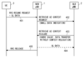
- FIG. 4 shows a second example of data transmission in RRC_INACTIVE according to this embodiment.
- Steps 401 to 405 of FIG. 4 are basically the same as steps 301 to 305 of FIG.
- the RETRIEVE UE CONTEXT REQUEST message in step 402 includes a new IE (e.g., UL DATA INDICATION) or a new cause value (e.g., Data available for transfer) indicating the existence of UL data.
- the RETRIEVE UE CONTEXT FAILURE message in step 403 includes a cause value (e.g., Data transfer without context relocation) indicating data transfer without UE context relocation.
- the RETRIEVE UE CONTEXT FAILURE message may include IE indicating the TNL information of old gNB2.
- FIG. 5 shows a third example of data transmission in RRC_INACTIVE according to this embodiment.
- new gNB1 already knows the TNL address of old gNB2, new gNB1 will be UL of UE3 prior to receiving the RETRIEVE UE CONTEXT FAILURE message (step 303). The data may be sent early.
- new gNB1 transmits UL data to old gNB2 after transmitting a RETRIEVE UE CONTEXT REQUEST message (step 502) (step 503).
- Steps 501, 502, 504, and 505 are similar to the corresponding steps of FIG. 3 or FIG.
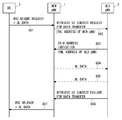
- FIG. 6 shows a fourth example of data transmission in RRC_INACTIVE according to this embodiment.
- Step 601 is the same as step 301 in FIG. 3, step 401 in FIG. 4, and step 501 in FIG.
- new gNB1 sends a different newly defined XnAP message to old gNB2 while including the information of the existing RETRIEVE UE CONTEXT REQUEST message.
- the new XnAP message may be a RETRIEVE UE CONTEXT REQUEST FOR DATA TRANSFER message, as shown in FIG.
- the notification of the TNL address of old gNB2 is sent from old gNB2 to new gNB1 via another XnAP message independent of the RETRIEVE UE CONTEXT FAILURE message (step 303). May be good.
- the old gNB 2 sends an XN-U ADDRESS INDICATION message to the new gNB 1 after receiving the RETRIEVE UE CONTEXT REQUEST FOR DATA TRANSFER message (step 602) (step 603).
- the XN-U ADDRESS INDICATION message indicates the TNL address (e.g., TEID and IP address) of old gNB2.
- the old gNB2 transmits a RETRIEVEUE CONTEXT FAILURE FOR DATA TRANSFER message (step 605).
- the Old gNB 2 may send a RETRIEVE UE CONTEXT FAILURE FOR DATA TRANSFER message after receiving the UL data of the UE 3 from the new gNB 1 (step 604) (step 605).
- the RETRIEVE UE CONTEXT FAILURE FOR DATA TRANSFER message includes an RRC Release message to be sent to the UE 3. Similar to step 305 of FIG. 3, in step 606, new gNB1 forwards the RRC Release message received in step 605 to UE3. Upon receiving the RRC Release message, UE3 remains in the RRC_INACTIVE state. As a result, UE3 can transmit UL data without moving from the RRC_INACTIVE state to the RRC_CONNECTED state.
- FIG. 7 shows a fifth example of data transmission in RRC_INACTIVE according to this embodiment.
- DL data is transmitted in addition to UL data.
- Steps 701 to 704 are, for example, the same as steps 301 to 304 in FIG. 3 or steps 401 to 404 in FIG.
- the old gNB 2 forwards the DL data of the UE 3 to the new gNB 1 via the Xn-U interface.
- the RETRIEVE UE CONTEXT REQUEST message in step 702 may include IE indicating the TNL information (e.g., TEID and IP address) of new gNB1.
- the IP address of new gNB1 used to transfer GTP-U / UDP / IP packets for the Xn-U interface is XnAP / SCTP / IP packets for the Xn-C interface (XnAP protocol). It may be the same as or different from the IP address of new gNB1 used for forwarding.
- the DL data transfer in step 705 may be performed before the UL data transfer in step 704, or may be performed in parallel with the UL data transfer in step 704.
- step 706 new gNB1 transmits the DL data received in step 705 to UE3 together with the RRC Release message included in the RETRIEVE UE CONTEXT FAILURE message received in step 703.
- UE3 Upon receiving the RRC Release message, UE3 remains in the RRC_INACTIVE state. As a result, UE3 can transmit UL data and receive DL data without moving from the RRC_INACTIVE state to the RRC_CONNECTED state.
- the procedure of FIG. 7 may be appropriately modified. For example, if new gNB1 already knows the TNL information of old gNB2, new gNB1 transfers the UL data of UE3 to old gNB2 on the Xn-U interface before receiving the RETRIEVE UE CONTEXT FAILURE message in step 703. You may send it. Furthermore, if old gNB2 already knows the TNL information of new gNB1, old gNB2 will transfer the DL data of UE3 to new gNB1 on the Xn-U interface before sending the RETRIEVE UE CONTEXT FAILURE message in step 703. You may send it. In addition, step 704 and step 705 may be performed before step 703.
- FIG. 8 shows a sixth example of data transmission in RRC_INACTIVE according to this embodiment.
- DL data transfer is added to the example shown in FIG.
- Step 801 is the same as step 601 of FIG.
- step 802 a newly defined XnAP message different from the existing RETRIEVE UE CONTEXT REQUEST message information is sent to old gNB2.
- the new XnAP message includes IE indicating the TNL information of new gNB1.
- the new XnAP message may be a RETRIEVE UE CONTEXT REQUEST FOR DATA TRANSFER message, as shown in FIG.
- Step 803 is the same as step 603 of FIG. Step 804 is similar to step 604 of FIG.
- the old gNB 2 forwards the DL data of the UE 3 to the new gNB 1 via the Xn-U interface.
- the DL data transfer in step 805 may be performed before the UL data transfer in step 804, or may be performed in parallel with the UL data transfer in step 804.
- Step 806 is the same as step 605 of FIG.
- the new gNB1 forwards the RRC Release message received via the RETRIEVE UE CONTEXT FAILURE FOR DATA TRANSFER message in step 806 to the UE 3.
- new gNB1 transmits the DL data received in step 805 to UE3 together with the RRC Release message.
- UE3 Upon receiving the RRC Release message, UE3 remains in the RRC_INACTIVE state. As a result, UE3 can transmit UL data and receive DL data without moving from the RRC_INACTIVE state to the RRC_CONNECTED state.
- the present embodiment provides a specific example of data transmission in RRC_INACTIVE described in the first embodiment.
- the configuration example of the wireless communication network according to the present embodiment is the same as the example shown in FIG.
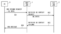
- FIG. 9 shows an example of data transmission in RRC_INACTIVE according to this embodiment.
- Step 901 is the same as step 301 in FIG.
- the new gNB1 sends a second type control message to the old gNB2 in response to receiving the UL data together with the RRCResumeRequest message. More specifically, in the example of FIG. 9, new gNB1 transmits an improved RETRIEVE UE CONTEXT REQUEST message containing a new IE containing the UL data (i.e., DTCH data) itself.
- the XnAP message in step 902 may be a new XnAP message that includes the information of the RETRIEVE UE CONTEXT REQUEST message but is different from the information.
- UL data (ie, DTCH data) is included in IE for a new transparent container (eg, New NG-RAN node To Old NG-RAN node Resume Container) from new gNB1 to old gNB2. May be good.
- the name of the new IE may be, for example, Data Over CP IE or Data Container IE.
- the New gNB1 may include in the XnAP message of step 902 additional information necessary to identify or decipher the UL data of UE3.
- the additional information may include a DRB ID and an LCID.
- Old gNB2 detects that the received RETRIEVE UE CONTEXT REQUEST message contains IE containing UL data (i.e., DTCH data). Then, old gNB2 decides not to relocate the UE context of UE3 to new gNB1. In step 903, the old gNB 2 transmits a RETRIEVE UE CONTEXT FAILURE message.
- the RETRIEVE UE CONTEXT FAILURE message includes an RRC Release message to be transmitted to the UE 3.
- the RRC Release message is included in the Old NG-RAN node To New NG-RAN node Resume Container IE in the RETRIEVE UE CONTEXT FAILURE message.
- the RETRIEVE UE CONTEXT FAILURE message may include a cause value (e.g., Non-relocation of context) indicating that the UE context is not relocated. Instead, the RETRIEVE UE CONTEXT FAILURE message may include a cause value (e.g., Data transfer without context relocation) indicating data transfer without UE context relocation.
- the XnAP message in step 903 may be a new XnAP message that includes the information of the RETRIEVEUE CONTEXT FAILURE message but is different from the information.
- new gNB1 forwards the RRC Release message received in step 903 to UE3.
- New gNB1 may send an RRC Release message in the fourth message (Msg4) of the 4-step random access procedure. Instead, new gNB1 may send an RRC Release message in the second message (message B (MsgB)) of the two-step random access procedure.
- MsgB messages B
- UE3 Upon receiving the RRC Release message, UE3 remains in the RRC_INACTIVE state. As a result, UE3 can transmit UL data without moving from the RRC_INACTIVE state to the RRC_CONNECTED state.
- the UL data of UE3 can be quickly transmitted at the same time as the first XnAP message from new gNB1 to old gNB2.
- the present embodiment provides a modified example of data transmission in RRC_INACTIVE described in the first to third embodiments.
- the configuration example of the wireless communication network according to the present embodiment is the same as the example shown in FIG.
- UE3 which is RRC_INACTIVE, transmits type information indicating the type of data activity to new gNB1 together with UL data and an RRC (connection) restart request message.
- the type information may be a new IE included in the RRC (connection) restart request message (e.g., RRC Resume Request message).
- the name of the new IE may be, for example, dataactivity IE.
- the new gNB1 of the present embodiment further receives the type information indicating the type of data activity of the UE3 from the UE3. Then, new gNB1 receives UL data from UE3 together with an RRCResumeRequest message, and sends a second type control message to old gNB2 when the UE context of UE3 is not available in new gNB1.
- the second type of control message requests old gNB2 to provide the UE context of UE3 and indicates the type of data activity of UE3.
- the second type of control message may be an improved RETRIEVE UE CONTEXT REQUEST message or a new XnAP message.
- the type of data activity in UE3 is the first type (eg, one-shot data) where there is only one UL data transmission, the occurrence of additional UL data transmissions following the first UL data transmission. From multiple types, including a second type (eg, more data) where is expected to occur, and a third type (eg, expect DL data) where DL data transmission is expected to occur after UL data transmission. May be selected.
- the data activity may be referred to as a data pattern or a traffic pattern.
- old gNB2 considers the type of data activity of UE3 and whether to send the (first) UL data of UE3, which is RRC_INACTIVE, to the core network (ie, 5GC) via old gNB2. You may decide. In other words, the old gNB 2 may decide whether to relocate (or provide) the UE context of the UE 3 to the new gNB 1 taking into account the type of data activity of the UE 3.
- FIG. 10 shows an example of the operation of new gNB1, old gNB2, and UE3 according to this embodiment.
- UE3 which is RRC_INACTIVE, transmits an RRC Resume Request message including IE (e.g., Data Activity IE) indicating the type of data activity and UL data to new gNB1.
- the RRCResumeRequest message and UL data may be sent in the third message of the 4-step contention-based random access procedure. Instead, the RRCResumeRequest message and UL data may be sent in the first message (message A (MsgA)) of the two-step contention-based random access procedure.
- MsgA message A
- new gNB1 transmits a RETRIEVE UE CONTEXT REQUEST message to old gNB2 in response to receiving UL data together with an RRC Resume Request message.
- old gNB2 is the last serving gNB of UE3.
- the RETRIEVE UE CONTEXT REQUEST message requests old gNB2 to provide the UE context of UE3.
- the RETRIEVE UE CONTEXT REQUEST message contains an information element (IE) indicating the type of data activity in UE3.
- the name of the IE may be Data Activity IE, Data Pattern IE, or Traffic Pattern IE.
- the RETRIEVE UE CONTEXT REQUEST message may include additional information elements as described in the first to third embodiments.
- the RETRIEVE UE CONTEXT REQUEST message may include a new IE or a new cause value indicating the existence of UL data. Further or instead, the RETRIEVE UE CONTEXT REQUEST message may include a new IE or new cause value representing a request for TNL information for old gNB2. Further or instead, the RETRIEVE UE CONTEXT REQUEST message may include a new IE containing the UL data (i.e., DTCH data) itself.
- old gNB2 determines whether to relocate (or provide) the UE context of UE3 to new gNB1 in consideration of the type of data activity of UE3. In other words, old gNB2 considers the type of data activity of UE3 and decides whether to send the (first) UL data of UE3, which is RRC_INACTIVE, to the core network (ie, 5GC) via old gNB2. do.
- old gNB2 does not relocate the UE context of UE3 to new gNB1 and outputs the UL data of UE3 which is RRC_INACTIVE. You may decide to send to the core network (ie, 5GC) via old gNB2. In contrast, old gNB2 sets the UE context of UE3 if the data activity type of UE3 is the above-mentioned second type (eg, more data) or third type (eg, expect DL data). You may decide to relocate to new gNB1.
- first type eg, one-shot data
- old gNB2 makes it possible to transfer the UL data (and DL data) of UE3 via old gNB2. This operation may be similar to any of the plurality of examples described in the first to fourth embodiments.
- old gNB2 provides the UE context of UE3 to new gNB1.
- new gNB1 receives the UE context of UE3 from old gNB2, decodes the UL data of UE3 using the UE context, extracts the IP data, and extracts the data from the core network node (ie, 5GC). It may be transmitted directly to (UPF) (that is, without going through old gNB2). Further, the new gNB1 may receive the DL data from the core network node and transmit it to the UE3.
- the core network node ie, 5GC
- new gNB1 is not an RRC Release message but an RRC Resume message. May be transmitted to UE3 in the fourth message of the 4-step random access procedure (or the second message of the 2-step random access procedure). In this case, UE3 may enter the RRC_CONNECTED state and transfer further (more) UL data, DL data, or both with new gNB1.
- UE3 which is RRC_INACTIVE, can provide its data activity type to new gNB1 and further provide it to old gNB2 via new gNB1. This can assist old gNB2 in deciding whether to relocate the UE context of UE3.
- the present embodiment provides a modified example of data transmission in RRC_INACTIVE described in the first to fourth embodiments.
- the data transmission in RRC_INACTIVE described in the first to fourth embodiments may be applied to the case of Inter-Radio Access Technology (RAT) ELISA mobility.
- RAT Inter-Radio Access Technology
- the LTE eNB may support the RRC_INACTIVE state of 5G UEs.
- UE3 in the RRC_INACTIVE state in the cell of NR gNB selects the cell of LTE ng-eNB (ie, inter-RAT cell reselection)
- UE3 remains in the RRC_INACTIVE state (that is, in the RRC_CONNECTED state or the RRC_IDLE state). You may stay in the cell of the ng-eNB (without moving).
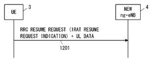
- UE3 becomes RRC_INACTIVE in the NR (New Radio) area (for example, cell of old gNB2), and then the cell of ng-eNB4 is selected by inter-RAT cell selection, and ng-eNB4 is selected. If the cell is included in the RNA specified by the RRC Release message of old gNB2, it may remain in the RRC_INACTIVE state.
- UE3 may transmit the RRC Resume Request message and UL data to ng-eNB 4 in the cell of ng-eNB 4.
- UE3 may include information (IE or Cause value) explicitly or implicitly indicating that it is an Inter-RAT resume in the RRC Resume Request message.
- the ng-eNB4 (ie, new RAN node) is transferred to the old gNB2 (ie, old RAN node or last serving RAN node).
- You may send a type of control message (eg, improved RETRIEVE UE CONTEXT REQUEST message or new XnAP message).
- UE3 becomes RRC_INACTIVE in the cell of ng-eNB (ie old ng-eNB), and after selecting the cell of gNB (ie new gNB), in the cell of gNB.
- UL data may be transmitted according to the RRC Resume procedure.
- the instruction to move from RRC_CONNECTED to RRC_INACTIVE to UE3 is whether UE3 can execute Inter-RAT INACTIVE mobility (that is, UE3 does it). Whether it is permitted or not) may be indicated explicitly or implicitly. To imply this, the indication may indicate that RNA contains cells of different RAT (e.g., LTE) or RAN area code (ranac). Further or instead, if the cell of the target RAT (eg, LTE ng-eNB) explicitly or implicitly indicates that Inter-RAT INACTIVE mobility is allowed, UE3 will do so. You may.
- the target RAT eg, LTE ng-eNB
- FIG. 13 is a block diagram showing a configuration example of gNB1 according to the above-described embodiment.
- the configuration examples of gNB2 and ng-eNB4 are the same as those in FIG.
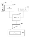
- gNB1 includes Radio Frequency (RF) transceiver 1301, network interface 1303, processor 1304, and memory 1305.
- RF transceiver 1301 performs analog RF signal processing to communicate with UEs including UE3.
- the RF transceiver 1301 may include a plurality of transceivers.
- the RF transceiver 1301 is coupled with the antenna array 1302 and the processor 1304.
- the RF transceiver 1301 receives the modulation symbol data from the processor 1304, generates a transmit RF signal, and supplies the transmit RF signal to the antenna array 1302. Further, the RF transceiver 1301 generates a baseband reception signal based on the reception RF signal received by the antenna array 1302, and supplies the baseband reception signal to the processor 1304.
- the RF transceiver 1301 may include an analog beamformer circuit for beamforming.
- the analog beamformer circuit includes, for example, a plurality of phase shifters and a plurality of power amplifiers.
- Network interface 1303 is used to communicate with network nodes (e.g., other gNBs, AMF, and User Plane Function (UPF)).
- the network interface 1303 may include, for example, a network interface card (NIC) compliant with the IEEE 802.3 series.
- Processor 1304 performs digital baseband signal processing (data plane processing) and control plane processing for wireless communication.
- Processor 1304 may include a plurality of processors.
- the processor 1304 includes a modem processor (eg, Digital Signal Processor (DSP)) that performs digital baseband signal processing and a protocol stack processor (eg, Central Processing Unit (CPU) or Micro Processing Unit (eg, Central Processing Unit (CPU)) that performs control plane processing. MPU)) may be included.
- DSP Digital Signal Processor
- MPU Central Processing Unit
- the digital baseband signal processing by the processor 1304 is performed by the ServiceDataAdaptationProtocol (SDAP) layer, the PacketDataConvergenceProtocol (PDCP) layer, the RadioLinkControl (RLC) layer, the MediumAccessControl (MAC) layer, and the Physical (PHY). ) Layer signal processing may be included.
- the control plane processing by the processor 1304 may include processing of Non-Access Stratum (NAS) messages, RRC messages, MAC CEs, and DCIs.
- NAS Non-Access Stratum
- Processor 1304 may include a digital beamformer module for beamforming.
- the digital beamformer module may include a MultipleInputMultipleOutput (MIMO) encoder and precoder.
- MIMO MultipleInputMultipleOutput
- the memory 1305 is composed of a combination of a volatile memory and a non-volatile memory.
- the volatile memory is, for example, Static Random Access Memory (SRAM) or Dynamic RAM (DRAM) or a combination thereof.
- the non-volatile memory is a mask ReadOnlyMemory (MROM), Electrically ErasableProgrammableROM (EEPROM), flash memory, or hard disk drive, or any combination thereof.
- Memory 1305 may include storage located away from processor 1304. In this case, processor 1304 may access memory 1305 via network interface 1303 or an I / O interface (not shown).
- the memory 1305 may store one or more software modules (computer programs) 1306 including instruction groups and data for performing processing by gNB1 described in the plurality of embodiments described above.
- processor 1304 may be configured to read the software module 1306 from memory 1305 and execute it to perform the processing of gNB1 described in the embodiments described above.
- gNB1 is a gNB Central Unit (gNB-CU) in a cloud RAN (C-RAN) deployment
- the gNB 1 does not have to include the RF transceiver 1301 (and the antenna array 1302).
- FIG. 14 is a block diagram showing a configuration example of UE3.
- Radio Frequency (RF) transceiver 1401 performs analog RF signal processing to communicate with NG-RAN nodes (e.g., gNB1, gNB2, and ng-eNB4).
- the RF transceiver 1401 may include a plurality of transceivers.
- the analog RF signal processing performed by the RF transceiver 1401 includes frequency up-conversion, frequency down-conversion, and amplification.
- the RF transceiver 1401 is coupled with the antenna array 1402 and the baseband processor 1403.
- the RF transceiver 1401 receives the modulation symbol data (or OFDM symbol data) from the baseband processor 1403, generates a transmit RF signal, and supplies the transmit RF signal to the antenna array 1402. Further, the RF transceiver 1401 generates a baseband reception signal based on the reception RF signal received by the antenna array 1402, and supplies the baseband reception signal to the baseband processor 1403.
- the RF transceiver 1401 may include an analog beamformer circuit for beamforming.
- the analog beamformer circuit includes, for example, a plurality of phase shifters and a plurality of power amplifiers.
- Baseband processor 1403 performs digital baseband signal processing (data plane processing) and control plane processing for wireless communication.
- Digital baseband signal processing includes (a) data compression / restoration, (b) data segmentation / concatenation, (c) transmission format (transmission frame) generation / decomposition, and (d) transmission path coding / decoding. , (E) Modulation (symbol mapping) / demodulation, and (f) Generation of OFDM symbol data (baseband OFDM signal) by Inverse Fast Fourier Transform (IFFT).
- the control plane processing includes layer 1 (eg, transmission power control), layer 2 (eg, wireless resource management, and hybrid automatic repeat request (HARQ) processing), and layer 3 (eg, attach, mobility, and call management). Includes communication management of).
- digital baseband signal processing by the baseband processor 1403 includes a ServiceDataAdaptationProtocol (SDAP) layer, a PacketDataConvergenceProtocol (PDCP) layer, a RadioLinkControl (RLC) layer, a MediumAccessControl (MAC) layer, and a Physical. (PHY) layer signal processing may be included.
- SDAP ServiceDataAdaptationProtocol
- PDCP PacketDataConvergenceProtocol
- RLC RadioLinkControl
- MAC MediumAccessControl
- PHY Physical.
- control plane processing by the baseband processor 1403 may include the processing of the Non-Access Stratum (NAS) protocol, the Radio Resource Control (RRC) protocol, and the MAC Control Elements (CEs).
- NAS Non-Access Stratum
- RRC Radio Resource Control
- CEs MAC Control Elements
- the baseband processor 1403 may perform Multiple Input Multiple Output (MIMO) encoding and precoding for beamforming.
- MIMO Multiple Input Multiple Output
- the baseband processor 1403 includes a modem processor (eg, Digital Signal Processor (DSP)) that performs digital baseband signal processing and a protocol stack processor (eg, Central Processing Unit (CPU) or Micro Processing Unit (eg, Central Processing Unit (CPU)) that performs control plane processing. MPU)) may be included.
- DSP Digital Signal Processor
- MPU Central Processing Unit
- the protocol stack processor that performs the control plane processing may be shared with the application processor 1404 described later.
- the application processor 1404 is also called a CPU, MPU, microprocessor, or processor core.
- the application processor 1404 may include a plurality of processors (a plurality of processor cores).
- the application processor 1404 includes a system software program (Operating System (OS)) read from memory 1406 or a memory (not shown) and various application programs (eg, call application, web browser, mailer, camera operation application, music playback). By executing the application), various functions of UE3 are realized.
- OS Operating System
- the baseband processor 1403 and application processor 1404 may be integrated on one chip, as shown by the dashed line (1405) in FIG.
- the baseband processor 1403 and the application processor 1404 may be implemented as one System on Chip (SoC) device 1405.
- SoC devices are sometimes referred to as system Large Scale Integration (LSI) or chipsets.
- Memory 1406 is a volatile memory, a non-volatile memory, or a combination thereof.
- the memory 1406 may include a plurality of physically independent memory devices.
- the volatile memory is, for example, Static Random Access Memory (SRAM) or Dynamic RAM (DRAM) or a combination thereof.
- the non-volatile memory is a mask ReadOnlyMemory (MROM), Electrically ErasableProgrammableROM (EEPROM), flash memory, or hard disk drive, or any combination thereof.
- MROM ReadOnlyMemory
- EEPROM Electrically ErasableProgrammableROM
- flash memory or hard disk drive, or any combination thereof.
- memory 1406 may include external memory devices accessible from baseband processor 1403, application processor 1404, and SoC 1405.
- the memory 1406 may include an internal memory device integrated in the baseband processor 1403, in the application processor 1404, or in the SoC 1405. Further, the memory 1406 may include the memory in the Universal Integrated Circuit Card (UICC).
- UICC Universal Integrated Circuit
- the memory 1406 may store one or more software modules (computer programs) 1407 that include instructions and data for performing processing by UE3 described in the plurality of embodiments described above.
- the baseband processor 1403 or application processor 1404 is configured to read the software module 1407 from memory 1406 and execute it to perform the UE3 processing described with reference to the drawings in the above embodiments. May be done.
- control plane processing and operation performed by UE3 described in the above-described embodiment is performed by other elements other than the RF transceiver 1401 and the antenna array 1402, that is, at least one of the baseband processor 1403 and the application processor 1404, and the software module 1407. It can be realized by the memory 1406 that stores the above.
- each of the processors included in the gNB1, gNB2, UE3, and ng-eNB4 causes the computer to perform the algorithm described with reference to the drawings.
- This program can be stored and supplied to a computer using various types of non-transitory computer readable medium.
- Non-temporary computer-readable media include various types of tangible storage mediums. Examples of non-temporary computer-readable media include magnetic recording media (eg flexible disks, magnetic tapes, hard disk drives), magneto-optical recording media (eg magneto-optical disks), CompactDiscReadOnlyMemory (CD-ROM), CD-ROM.
- the program may also be supplied to the computer by various types of temporary computer readable medium.
- temporary computer-readable media include electrical, optical, and electromagnetic waves.
- the temporary computer-readable medium can supply the program to the computer via a wired communication path such as an electric wire and an optical fiber, or a wireless communication path.
- the 2-step random access (2-Step RA) procedure is used to transmit UL data (DTCH data) by UE3 in the above embodiment
- fallback to the 4-step random access (4-Step RA) procedure May be done.
- UE3 transmits UL data together with an RRC (connection) restart request message (e.g., RRC Resume Request message) in the first message (MsgA) of the 2-Step RA procedure.
- RRC connection
- New gNB1 was able to detect the random access preamble of the first message (MsgA), but if it could not correctly decrypt the data (payload) of the first message (MsgA), it would fall back to the 4-Step RA procedure.
- a random access response (fallback RAR) indicating a notification may be sent to UE3 in the second message (MsgB) of the 2Step RA procedure.
- UE3 receives the fallback notification to the 4-Step RA procedure, it sends the RRC (connection) in the third message (Msg3) of the 4-Step RA procedure and the first message (MsgA) of the 2-Step RA procedure.
- RRC connection
- Msg3 third message
- MsgA first message
- new gNB1, old gNB2 and UE3 may perform the same operation as the above-described embodiment using the 4-Step RA procedure.
- the transmission of UL data (DTCH data) by UE3 in the above-described embodiment is performed in the RRC_INACTIVE state. More specifically, this may be done as follows.
- UE3 receives an RRC Release message including an instruction (SuspendConfig) to move from the RRC_CONNECTED state to the RRC_INACTIVE state, it saves the UE context.
- This UE context is also called a UE Access Stratum (AS) context or a UE Inactive AS context.
- AS UE Access Stratum
- the UE context includes, for example, the current security information, the cell identifier (cellIdentity, PCI) of the serving cell (PCell), the C-RNTI assigned to UE3, the IP data (QoS flow) of the SDAP layer, and the correspondence between the DRB (QoS). Information on flow to DRB mapping rule) is included. Further, the UE 3 may determine whether or not the information indicating that the UL data transmission in the RRC_INACTIVE state is permitted is included in the RRC Release message (for example, SuspendConfig).
- the RRC Release message for example, SuspendConfig
- UE3 when UE3 is in the RRC_INACTIVE state, when the upper layer (Non-access stratum (NAS) layer) of UE3 notifies that there is data to be transmitted to the RRC layer (AS layer), the RRC layer of UE3 is in the RRC_INACTIVE state. Determine if UL data transmission is permitted in. In addition, UE3 may determine if it is allowed (or supported) in the serving cell (Camping cell in the RRC_INACTIVE state). If UE3 is allowed to send UL data in the RRC_INACTIVE state (and if it is allowed in the serving cell), it retrieves the required information from the UE context it holds and resumes RRC (connection). Start the request procedure.
- NAS Non-access stratum
- UL data is transmitted by the third message (Msg3), and the 2-step random access (2-Step) is performed.
- RA When the procedure is performed, UL data is transmitted in the data part (MsgA payload) of the first message.
- the RRCResumeRequest message sent together with the UL data has a Cause value (eg UL-data-Inactive, mo-Data-Inactive) indicating that UL data transmission is involved (or is intended for it). It may be included.
- the UE 3 receives the RRC Release message in response to the RRC Resume Request message, the UE 3 remains in the RRC_INACTIVE state.
- the setting information may include, for example, RAN area information (e.g. ran-NotificationAreaInfo) and security information (e.g. nextHopChainingCount).
- the setting information may include information indicating whether or not the UE3 is permitted to perform data transmission in the RRC Resume (in other words, whether or not the UE3 is permitted to perform the data transmission).
- the information may further indicate which of the one or more DRBs set in UE3 is allowed to transmit data in the RRC Resume.
- the UE3 can transmit the UL data in the RRC_INACTIVE state in the serving cell in which the UL data is staying at the time when the UL data is generated again.
- the RRCResume message in response to the RRCResumeRequest message, it shifts to the RRC_CONNECTED state.
- the IP address of the old gNB2 used to transfer the GTP-U / UDP / IP packets for the Xn-U interface is the Xn-C interface (GTP-C tunnel). It may be the same as the IP address of old gNB2 used to transfer XnAP / SCTP / IP packets related to (XnAP protocol). Old gNB2 may signal new gNB1 in advance to notify new gNB1 that the same IP address will be used for both the Xn-U interface and the Xn-C interface.
- the IP address of new gNB1 used to transfer GTP-U / UDP / IP packets for the Xn-U interface is XnAP / SCTP / for the Xn-C interface (XnAP protocol). It may be the same as the IP address of new gNB1 used to transfer IP packets.
- New gNB1 may signal old gNB2 in advance to notify old gNB2 that the same IP address will be used for both the Xn-U interface and the Xn-C interface.
- the above embodiment may be implemented in LTE. Specifically, the above embodiment is applied when UE3 transmits UL data in the RRC_INACTIVE state in the LTE eNB (or its sophistication) cell connected to the EPC (or its sophistication). May be good. More specifically, if neweNB receives UL data from UE3 with an RRC (connection) restart request message and the UE context of UE3 is not available in neweNB, neweNB is the second type in the X2 interface. Send a control message to old eNB. The old eNB decides whether to send UL data to the core network (i.e. EPC) via the old eNB or to send the UE context to the new eNB.
- EPC core network
- the old eNB decides to send UL data to the core network via the old eNB, it may send the TNL information of the old eNB to the new eNB.
- the new eNB may send UL data to the old eNB.
- UL data can be transmitted to the core network without moving the UE context of UE3 from old eNB to new eNB.
- new gNB1 (or new ng-eNB4), old gNB2, and UE3 described in the above embodiment is a cell selection (intra-RAT inter) between the LTE eNB cell and the ng-eNB cell by the UE.
- -It may be carried out in the system cell selection), or it may be carried out in the inter-RAT cell selection between the LTE eNB cell and the gNB cell.
- the operations of new gNB1 (or new ng-eNB4) and old gNB2 described in the above-described embodiment may be performed between LTE eNB and ng-eNB, and between LTE eNB and gNB. It may be carried out.
- the first Radio Access Network (RAN) node With at least one memory With at least one processor coupled to the at least one memory With The at least one processor
- the radio when an RRC restart request message without uplink data is received from a radio terminal in the Radio Resource Control (RRC) _INACTIVE state and the radio terminal context of the radio terminal is not available at the first RAN node.
- RRC Radio Resource Control
- a first type of control message requesting terminal context is configured to be sent to the second RAN node, which is the nearest serving RAN node of the wireless terminal.
- a second type of control message distinguished from the first type of control message is configured to be sent to the second RAN node.
- First RAN node. (Appendix 2)
- the second type of control message is distinguished from the first type of control message by including an indication that the second type of control message directly or indirectly represents the presence of the uplink data.
- the first RAN node described in Appendix 1. (Appendix 3)
- the second type of control message is such that the first type of control message includes a display in which the second type of control message represents a request for transport network layer (TNL) information of the second type of RAN node.
- TNL transport network layer
- the at least one processor A third control message is configured to be received from the second RAN node after transmission of the second type control message.
- the third control message is configured to transmit the uplink data to the second RAN node in response to indicating that the radio terminal context is not being relocated.
- the first RAN node according to any one of Appendix 1 to 3.
- the at least one processor A third control message is configured to be received from the second RAN node after transmission of the second type control message.
- the third control message is configured to transmit the uplink data to the second RAN node in response to indicating permission to transfer uplink data through the second RAN node.
- the first RAN node according to any one of Appendix 1 to 3.
- the at least one processor After transmitting the second type control message, the at least one processor sends a third control message indicating transport network layer (TNL) information of the second RAN node from the second RAN node.
- the uplink data is configured to be transmitted to the second RAN node in response to the receipt.
- the first RAN node according to any one of Appendix 1 to 3.
- the second type of control message is distinguished from the first type of control message by the inclusion of the uplink data itself in the second type of control message.
- the at least one processor is configured to include additional information necessary to identify or decode the uplink data in the second type of control message.
- the additional information includes one or both of the data radio bearer identifier and the logical channel identifier.
- the first RAN node described in Appendix 8. (Appendix 10)
- the at least one processor It is configured to receive type information indicating the type of data activity from the wireless terminal along with the uplink data. It is configured to inform the second RAN node of the type of data activity via the control message of the second type.
- the first RAN node according to any one of Appendix 1 to 9.
- the type of data activity is a first type in which only the transmission of the uplink data is performed, a second type in which an additional uplink data transmission is expected following the transmission of the uplink data.
- the first RAN node according to Appendix 10.
- the at least one processor is configured to include the transport network layer (TNL) information of the first RAN node in the second type of control message.
- the first RAN node according to any one of Appendix 1 to 11.
- the second Radio Access Network (RAN) node With at least one memory With at least one processor coupled to the at least one memory With The at least one processor Radio Resource Control (RRC) _INACTIVE is configured to hold the radio terminal context of the radio terminal in the state.
- a control message requesting the wireless terminal context is configured to be received from the first RAN node.
- the control message is configured to determine if the first RAN node is of a particular type used when uplink data is received with the RRC restart request message from the radio terminal in the RRC_INACTIVE state.
- NS Second RAN node.
- the particular type is distinguished from the other types by including an indication that the control message directly or indirectly represents the presence of the uplink data.
- the particular type is distinguished from the other types by including a display in which the control message represents a request for transport network layer (TNL) information of the second RAN node.
- TNL transport network layer
- Appendix 16 The particular type is distinguished from the other types by the control message including the uplink data itself.
- the second RAN node described in Appendix 13. The at least one processor, if the control message is of the particular type, provides the uplink data via the second RAN node without providing the radio terminal context to the first RAN node. Configured to send to the core network, The second RAN node according to any one of Appendix 13 to 16. (Appendix 18) The at least one processor is configured to determine whether to transmit the uplink data to the core network via the second RAN node if the control message is of the particular type. The second RAN node according to any one of Appendix 13 to 17.
- the at least one processor transmits the uplink data to the core network via the second RAN node, taking into account the type of data activity of the radio terminal indicated by the control message. Configured to decide, The second RAN node according to Appendix 18.
- the type of data activity is a first type in which only the transmission of the uplink data is performed, a second type in which an additional uplink data transmission is expected following the transmission of the uplink data. And selected from a plurality of types, including a third type in which downlink data transmission is expected to occur after the uplink data transmission.
- the at least one processor has determined to transmit the uplink data to the core network via the second RAN node in response to the transport network layer of the second RAN node.
- TNL configured to send a control message indicating information to the first RAN node.
- the second RAN node according to any one of Appendix 18 to 20.
- the at least one processor indicates that the radio terminal context will not be relocated in response to the decision to transmit the uplink data to the core network via the second RAN node. It is configured to send a control message to the first RAN node.
- the second RAN node according to any one of Appendix 18 to 20.
- (Appendix 23) In response to the decision of the at least one processor to transmit the uplink data to the core network via the second RAN node, the uplink data transfer via the second RAN node.
- a control message indicating permission is configured to be sent to the first RAN node.
- the second RAN node according to any one of Appendix 18 to 20.
- (Appendix 24) It ’s a wireless terminal, With at least one memory With at least one processor coupled to the at least one memory With The at least one processor provides type information indicating the type of uplink data and data activity when the radio terminal is in the Radio Resource Control (RRC) _INACTIVE state, along with a Radio Access Network (RAN) node with an RRC restart request message. Configured to send to Wireless terminal.
- RRC Radio Resource Control
- RAN Radio Access Network
- the at least one processor expects the type of data activity to occur in the first type, which is only the transmission of the uplink data, an additional uplink data transmission following the uplink data. It is configured to select from a plurality of types, including a second type and a third type in which downlink data transmission is expected to occur after transmission of the uplink data.
- the wireless terminal according to Appendix 24. (Appendix 26) The type information is included in the RRC restart request message.
- RAN Radio Access Network
- the radio when an RRC restart request message without uplink data is received from a radio terminal in the Radio Resource Control (RRC) _INACTIVE state and the radio terminal context of the radio terminal is not available in the first RAN node.
- RRC Radio Resource Control
- a second type of control message that requests the wireless terminal context and is distinguished from the first type of control message when received with the message and the wireless terminal context is not available at the first RAN node. Sending to the second RAN node, How to prepare.
- (Appendix 28) A method performed by a second Radio Access Network (RAN) node, Preserving the radio terminal context of a radio terminal in the Radio Resource Control (RRC) _INACTIVE state, The control message requesting the wireless terminal context is received from the first RAN node, and the control message is the uplink data from the wireless terminal in which the first RAN node is in the RRC_INACTIVE state together with the RRC restart request message. Determining if it is a particular type used when received, How to prepare.
- RAN Radio Access Network
- RRC Radio Resource Control
- (Appendix 29) It is a method performed by a wireless terminal, Sending type information indicating the type of uplink data and data activity to the Radio Access Network (RAN) node along with an RRC resume request message when the radio terminal is in the Radio Resource Control (RRC) _INACTIVE state. How to prepare.
- (Appendix 30) A program that lets a computer do the method for the first Radio Access Network (RAN) node. The method is The radio when an RRC restart request message without uplink data is received from a radio terminal in the Radio Resource Control (RRC) _INACTIVE state and the radio terminal context of the radio terminal is not available at the first RAN node.
- a first-type control message requesting a terminal context to a second RAN node which is the nearest serving RAN node of the radio terminal, and requesting the uplink data from the radio terminal in the RRC_INACTIVE state to resume the RRC.
- a second type of control message that requests the wireless terminal context and is distinguished from the first type of control message when received with the message and the wireless terminal context is not available at the first RAN node.
- Sending to the second RAN node A program that includes. (Appendix 31) A program that lets a computer do the method for a second Radio Access Network (RAN) node.
- RAN Radio Access Network
- the method is Preserving the radio terminal context of a radio terminal in the Radio Resource Control (RRC) _INACTIVE state,
- the control message requesting the wireless terminal context is received from the first RAN node, and the control message is the uplink data from the wireless terminal in which the first RAN node is in the RRC_INACTIVE state together with the RRC restart request message.
- Determining if it is a particular type used when received A program that includes. (Appendix 32) A program that lets a computer do the method for a wireless terminal The method sends uplink data and type information indicating the type of data activity to the Radio Access Network (RAN) node along with an RRC restart request message when the radio terminal is in the Radio Resource Control (RRC) _INACTIVE state. Prepare for program.
- RAN Radio Access Network
- RRC Radio Resource Control
Landscapes
- Engineering & Computer Science (AREA)
- Signal Processing (AREA)
- Computer Networks & Wireless Communication (AREA)
- Computer Security & Cryptography (AREA)
- Databases & Information Systems (AREA)
- Mobile Radio Communication Systems (AREA)
Abstract
Description
(a)Radio Resource Control (RRC)_INACTIVE状態の無線端末からアップリンクデータを伴わないRRC再開要求メッセージを受信し、且つ前記無線端末の無線端末コンテキストが前記第1のRANノードにおいて利用可能でない場合に、前記無線端末コンテキストを要求する第1タイプの制御メッセージを前記無線端末の直近のサービングRANノードである第2のRANノードに送ること、及び
(b)前記RRC_INACTIVE状態の前記無線端末から前記アップリンクデータを前記RRC再開要求メッセージと共に受信し、且つ前記無線端末コンテキストが前記第1のRANノードにおいて利用可能でない場合に、前記無線端末コンテキストを要求し且つ前記第1タイプの制御メッセージと区別された第2タイプの制御メッセージを前記第2のRANノードに送ること。
(a)Radio Resource Control (RRC)_INACTIVE状態の無線端末の無線端末コンテキストを保持すること、
(b)前記無線端末コンテキストを要求する制御メッセージを第1のRANノードから受信すること、及び
(c)前記制御メッセージが、前記第1のRANノードが前記RRC_INACTIVE状態の前記無線端末からアップリンクデータをRRC再開要求メッセージと共に受信した場合に使用される特定のタイプであるか否かを判定すること。
図1は、本実施形態を含む幾つかの実施形態に係る無線通信ネットワーク(i.e., 5GS)の構成例を示している。図1の例は、無線通信ネットワークは、2つの無線アクセスネットワーク(Radio Access Network(RAN))ノード(i.e., gNBs)1及び2並びに無線端末(i.e., UE)3を含む。以下で詳細に説明するように、UE3はRRC_INACTIVEでのスモールデータ送信を行うためにエアインタフェース101を介してgNB1にアクセスすることができ、gNB1はノード間インタフェース102を介してRRC_INACTIVEであるUE3のUEコンテキストを持つgNB2と通信する。したがって、以下では、gNB1はnew gNBと呼ばれ、gNB2はold gNB又は(last serving gNBと呼ばれる。old gNBは、UE3に対する直近のサービングRANノードと表現することもできる。
本実施形態は、第1の実施形態で説明されたRRC_INACTIVEでのデータ送信の具体例を提供する。本実施形態に係る無線通信ネットワークの構成例は、図1に示された例と同様である。
本実施形態は、第1の実施形態で説明されたRRC_INACTIVEでのデータ送信の具体例を提供する。本実施形態に係る無線通信ネットワークの構成例は、図1に示された例と同様である。
本実施形態は、第1~第3の実施形態で説明されたRRC_INACTIVEでのデータ送信の変形例を提供する。本実施形態に係る無線通信ネットワークの構成例は、図1に示された例と同様である。
本実施形態は、第1~第4の実施形態で説明されたRRC_INACTIVEでのデータ送信の変形例を提供する。第1~第4の実施形態で説明されたRRC_INACTIVEでのデータ送信は、Inter-Radio Access Technology (RAT) INACTIVE mobilityのケースに適用されてもよい。より具体的には、5GSと協調動作する機能を持つLTE eNB(ng-eNBとも呼ばれる)が使用される場合、当該LTE eNBは、5G UEsのRRC_INACTIVE状態をサポートしてもよい。このとき、NR gNBのセルにおいてRRC_INACTIVE状態のUE3が、LTE ng-eNBのセルを選択(i.e., inter-RATセル再選択)する場合、UE3はRRC_INACTIVE状態のまま(つまり、RRC_CONNECTED状態またはRRC_IDLE状態に移ることなく)当該ng-eNBのセルに滞在してもよい。
上述の実施形態は、各々独立に実施されてもよいし、実施形態全体又はその一部が適宜組み合わせて実施されてもよい。
第1のRadio Access Network(RAN)ノードであって、
少なくとも1つのメモリと、
前記少なくとも1つのメモリに結合された少なくとも1つのプロセッサと、
を備え、
前記少なくとも1つのプロセッサは、
Radio Resource Control (RRC)_INACTIVE状態の無線端末からアップリンクデータを伴わないRRC再開要求メッセージを受信し、且つ前記無線端末の無線端末コンテキストが前記第1のRANノードにおいて利用可能でない場合に、前記無線端末コンテキストを要求する第1タイプの制御メッセージを前記無線端末の直近のサービングRANノードである第2のRANノードに送るよう構成され、
前記RRC_INACTIVE状態の前記無線端末から前記アップリンクデータを前記RRC再開要求メッセージと共に受信し、且つ前記無線端末コンテキストが前記第1のRANノードにおいて利用可能でない場合に、前記無線端末コンテキストを要求し且つ前記第1タイプの制御メッセージと区別された第2タイプの制御メッセージを前記第2のRANノードに送るよう構成される、
第1のRANノード。
(付記2)
前記第2タイプの制御メッセージは、前記第2タイプの制御メッセージが前記アップリンクデータの存在を直接的に又は間接的に表す表示を含むことによって、前記第1タイプの制御メッセージと区別される、
付記1に記載の第1のRANノード。
(付記3)
前記第2タイプの制御メッセージは、前記第2タイプの制御メッセージが前記第2のRANノードのトランスポート・ネットワーク・レイヤ(TNL)情報の要求を表す表示を含むことによって、前記第1タイプの制御メッセージと区別される、
付記1に記載の第1のRANノード。
(付記4)
前記少なくとも1つのプロセッサは、
前記第2タイプの制御メッセージの送信後に第3の制御メッセージを前記第2のRANノードから受信するよう構成され、
前記第3の制御メッセージが前記無線端末コンテキストのリロケーションが行われないことを示すことに応答して、前記アップリンクデータを前記第2のRANノードに送信するよう構成される、
付記1~3のいずれか1項に記載の第1のRANノード。
(付記5)
前記少なくとも1つのプロセッサは、
前記第2タイプの制御メッセージの送信後に第3の制御メッセージを前記第2のRANノードから受信するよう構成され、
前記第3の制御メッセージが前記第2のRANノードを介するアップリンクデータ転送の許可を示すことに応答して、前記アップリンクデータを前記第2のRANノードに送信するよう構成される、
付記1~3のいずれか1項に記載の第1のRANノード。
(付記6)
前記少なくとも1つのプロセッサは、前記第2タイプの制御メッセージの送信後に、前記第2のRANノードのトランスポート・ネットワーク・レイヤ(TNL)情報を示す第3の制御メッセージを前記第2のRANノードから受信したことに応答して、前記アップリンクデータを前記第2のRANノードに送信するよう構成される、
付記1~3のいずれか1項に記載の第1のRANノード。
(付記7)
前記第2タイプの制御メッセージは、前記第2タイプの制御メッセージが前記アップリンクデータそれ自体を含むことによって、前記第1タイプの制御メッセージと区別される、
付記1に記載の第1のRANノード。
(付記8)
前記少なくとも1つのプロセッサは、前記アップリンクデータを特定するため又は復号化するために必要な追加情報を前記第2タイプの制御メッセージに含めるよう構成される、
付記7に記載の第1のRANノード。
(付記9)
前記追加情報は、データ無線ベアラ識別子及び論理チャネル識別子のうち一方又は両方を含む、
付記8に記載の第1のRANノード。
(付記10)
前記少なくとも1つのプロセッサは、
データ活動のタイプを示すタイプ情報を前記アップリンクデータと共に前記無線端末から受信するよう構成され、
前記データ活動の前記タイプを前記第2のRANノードに前記第2タイプの制御メッセージを介して知らせるよう構成される、
付記1~9のいずれか1項に記載の第1のRANノード。
(付記11)
前記データ活動の前記タイプは、前記アップリンクデータの送信のみである第1のタイプ、前記アップリンクデータの送信に引き続く追加のアップリンクデータ送信の発生が予定される(expected)第2のタイプ、及び前記アップリンクデータの送信後にダウンリンクデータ送信の発生が予定される第3のタイプを含む複数のタイプから選択される、
付記10に記載の第1のRANノード。
(付記12)
前記少なくとも1つのプロセッサは、前記第1のRANノードのトランスポート・ネットワーク・レイヤ(TNL)情報を前記第2タイプの制御メッセージに含めるよう構成される、
付記1~11のいずれか1項に記載の第1のRANノード。
(付記13)
第2のRadio Access Network(RAN)ノードであって、
少なくとも1つのメモリと、
前記少なくとも1つのメモリに結合された少なくとも1つのプロセッサと、
を備え、
前記少なくとも1つのプロセッサは、
Radio Resource Control (RRC)_INACTIVE状態の無線端末の無線端末コンテキストを保持するよう構成され、
前記無線端末コンテキストを要求する制御メッセージを第1のRANノードから受信するよう構成され、
前記制御メッセージが、前記第1のRANノードが前記RRC_INACTIVE状態の前記無線端末からアップリンクデータをRRC再開要求メッセージと共に受信した場合に使用される特定のタイプであるか否かを判定するよう構成される、
第2のRANノード。
(付記14)
前記特定のタイプは、前記制御メッセージが前記アップリンクデータの存在を直接的に又は間接的に表す表示を含むことによって、他のタイプと区別される、
付記13に記載の第2のRANノード。
(付記15)
前記特定のタイプは、前記制御メッセージが前記第2のRANノードのトランスポート・ネットワーク・レイヤ(TNL)情報の要求を表す表示を含むことによって、他のタイプと区別される、
付記13に記載の第2のRANノード。
(付記16)
前記特定のタイプは、前記制御メッセージが前記アップリンクデータそれ自体を含むことによって、他のタイプと区別される、
付記13に記載の第2のRANノード。
(付記17)
前記少なくとも1つのプロセッサは、前記制御メッセージが前記特定のタイプであるなら、前記無線端末コンテキストを前記第1のRANノードに提供せずに、前記アップリンクデータを前記第2のRANノードを介してコアネットワークに送信するよう構成される、
付記13~16のいずれか1項に記載の第2のRANノード。
(付記18)
前記少なくとも1つのプロセッサは、前記制御メッセージが前記特定のタイプである場合、前記アップリンクデータを前記第2のRANノードを介してコアネットワークに送信するか否かを決定するよう構成される、
付記13~17のいずれか1項に記載の第2のRANノード。
(付記19)
前記少なくとも1つのプロセッサは、前記制御メッセージによって示される前記無線端末のデータ活動のタイプを考慮して、前記アップリンクデータを前記第2のRANノードを介して前記コアネットワークに送信するか否かを決定するよう構成される、
付記18に記載の第2のRANノード。
(付記20)
前記データ活動の前記タイプは、前記アップリンクデータの送信のみである第1のタイプ、前記アップリンクデータの送信に引き続く追加のアップリンクデータ送信の発生が予定される(expected)第2のタイプ、及び前記アップリンクデータの送信後にダウンリンクデータ送信の発生が予定される第3のタイプを含む複数のタイプから選択される、
付記19に記載の第2のRANノード。
(付記21)
前記少なくとも1つのプロセッサは、前記アップリンクデータを前記第2のRANノードを介して前記コアネットワークに送信することを決定したことに応答して、前記第2のRANノードのトランスポート・ネットワーク・レイヤ(TNL)情報を示す制御メッセージを前記第1のRANノードに送るよう構成される、
付記18~20のいずれか1項に記載の第2のRANノード。
(付記22)
前記少なくとも1つのプロセッサは、前記アップリンクデータを前記第2のRANノードを介して前記コアネットワークに送信することを決定したことに応答して、前記無線端末コンテキストのリロケーションが行われないことを示す制御メッセージを前記第1のRANノードに送るよう構成される、
付記18~20のいずれか1項に記載の第2のRANノード。
(付記23)
前記少なくとも1つのプロセッサは、前記アップリンクデータを前記第2のRANノードを介して前記コアネットワークに送信することを決定したことに応答して、前記第2のRANノードを介するアップリンクデータ転送の許可を示す制御メッセージを前記第1のRANノードに送るよう構成される、
付記18~20のいずれか1項に記載の第2のRANノード。
(付記24)
無線端末であって、
少なくとも1つのメモリと、
前記少なくとも1つのメモリに結合された少なくとも1つのプロセッサと、
を備え、
前記少なくとも1つのプロセッサは、前記無線端末がRadio Resource Control (RRC)_INACTIVE状態であるときに、アップリンクデータとデータ活動のタイプを示すタイプ情報を、RRC再開要求メッセージと共にRadio Access Network(RAN)ノードに送信するよう構成される、
無線端末。
(付記25)
前記少なくとも1つのプロセッサは、前記データ活動の前記タイプを、前記アップリンクデータの送信のみである第1のタイプ、前記アップリンクデータに引き続く追加のアップリンクデータ送信の発生が予定される(expected)第2のタイプ、及び前記アップリンクデータの送信後にダウンリンクデータ送信の発生が予定される第3のタイプを含む複数のタイプから選択するよう構成される、
付記24に記載の無線端末。
(付記26)
前記タイプ情報は、前記RRC再開要求メッセージに含まれる、
付記24又は25に記載の無線端末。
(付記27)
第1のRadio Access Network(RAN)ノードにより行われる方法であって、
Radio Resource Control (RRC)_INACTIVE状態の無線端末からアップリンクデータを伴わないRRC再開要求メッセージを受信し、且つ前記無線端末の無線端末コンテキストが前記第1のRANノードにおいて利用可能でない場合に、前記無線端末コンテキストを要求する第1タイプの制御メッセージを前記無線端末の直近のサービングRANノードである第2のRANノードに送ること、及び
前記RRC_INACTIVE状態の前記無線端末から前記アップリンクデータを前記RRC再開要求メッセージと共に受信し、且つ前記無線端末コンテキストが前記第1のRANノードにおいて利用可能でない場合に、前記無線端末コンテキストを要求し且つ前記第1タイプの制御メッセージと区別された第2タイプの制御メッセージを前記第2のRANノードに送ること、
を備える方法。
(付記28)
第2のRadio Access Network(RAN)ノードにより行われる方法であって、
Radio Resource Control (RRC)_INACTIVE状態の無線端末の無線端末コンテキストを保持すること、
前記無線端末コンテキストを要求する制御メッセージを第1のRANノードから受信すること、及び
前記制御メッセージが、前記第1のRANノードが前記RRC_INACTIVE状態の前記無線端末からアップリンクデータをRRC再開要求メッセージと共に受信した場合に使用される特定のタイプであるか否かを判定すること、
を備える方法。
(付記29)
無線端末により行われる方法であって、
前記無線端末がRadio Resource Control (RRC)_INACTIVE状態であるときに、アップリンクデータとデータ活動のタイプを示すタイプ情報を、RRC再開要求メッセージと共にRadio Access Network(RAN)ノードに送信すること、
を備える方法。
(付記30)
第1のRadio Access Network(RAN)ノードのための方法をコンピュータに行わせるプログラムであって、
前記方法は、
Radio Resource Control (RRC)_INACTIVE状態の無線端末からアップリンクデータを伴わないRRC再開要求メッセージを受信し、且つ前記無線端末の無線端末コンテキストが前記第1のRANノードにおいて利用可能でない場合に、前記無線端末コンテキストを要求する第1タイプの制御メッセージを前記無線端末の直近のサービングRANノードである第2のRANノードに送ること、及び
前記RRC_INACTIVE状態の前記無線端末から前記アップリンクデータを前記RRC再開要求メッセージと共に受信し、且つ前記無線端末コンテキストが前記第1のRANノードにおいて利用可能でない場合に、前記無線端末コンテキストを要求し且つ前記第1タイプの制御メッセージと区別された第2タイプの制御メッセージを前記第2のRANノードに送ること、
を備える、プログラム。
(付記31)
第2のRadio Access Network(RAN)ノードのための方法をコンピュータに行わせるプログラムであって、
前記方法は、
Radio Resource Control (RRC)_INACTIVE状態の無線端末の無線端末コンテキストを保持すること、
前記無線端末コンテキストを要求する制御メッセージを第1のRANノードから受信すること、及び
前記制御メッセージが、前記第1のRANノードが前記RRC_INACTIVE状態の前記無線端末からアップリンクデータをRRC再開要求メッセージと共に受信した場合に使用される特定のタイプであるか否かを判定すること、
を備える、プログラム。
(付記32)
無線端末のための方法をコンピュータに行わせるプログラムであって、
前記方法は、前記無線端末がRadio Resource Control (RRC)_INACTIVE状態であるときに、アップリンクデータとデータ活動のタイプを示すタイプ情報を、RRC再開要求メッセージと共にRadio Access Network(RAN)ノードに送信することを備える、
プログラム。
2 gNB
3 UE
4 ng-eNB
1304 プロセッサ
1305 メモリ
1306 モジュール(modules)
1403 ベースバンドプロセッサ
1404 アプリケーションプロセッサ
1406 メモリ
1407 モジュール(modules)
Claims (32)
- 第1のRadio Access Network(RAN)ノードであって、
少なくとも1つのメモリと、
前記少なくとも1つのメモリに結合された少なくとも1つのプロセッサと、
を備え、
前記少なくとも1つのプロセッサは、
Radio Resource Control (RRC)_INACTIVE状態の無線端末からアップリンクデータを伴わないRRC再開要求メッセージを受信し、且つ前記無線端末の無線端末コンテキストが前記第1のRANノードにおいて利用可能でない場合に、前記無線端末コンテキストを要求する第1タイプの制御メッセージを前記無線端末の直近のサービングRANノードである第2のRANノードに送るよう構成され、
前記RRC_INACTIVE状態の前記無線端末から前記アップリンクデータを前記RRC再開要求メッセージと共に受信し、且つ前記無線端末コンテキストが前記第1のRANノードにおいて利用可能でない場合に、前記無線端末コンテキストを要求し且つ前記第1タイプの制御メッセージと区別された第2タイプの制御メッセージを前記第2のRANノードに送るよう構成される、
第1のRANノード。 - 前記第2タイプの制御メッセージは、前記第2タイプの制御メッセージが前記アップリンクデータの存在を直接的に又は間接的に表す表示を含むことによって、前記第1タイプの制御メッセージと区別される、
請求項1に記載の第1のRANノード。 - 前記第2タイプの制御メッセージは、前記第2タイプの制御メッセージが前記第2のRANノードのトランスポート・ネットワーク・レイヤ(TNL)情報の要求を表す表示を含むことによって、前記第1タイプの制御メッセージと区別される、
請求項1に記載の第1のRANノード。 - 前記少なくとも1つのプロセッサは、
前記第2タイプの制御メッセージの送信後に第3の制御メッセージを前記第2のRANノードから受信するよう構成され、
前記第3の制御メッセージが前記無線端末コンテキストのリロケーションが行われないことを示すことに応答して、前記アップリンクデータを前記第2のRANノードに送信するよう構成される、
請求項1~3のいずれか1項に記載の第1のRANノード。 - 前記少なくとも1つのプロセッサは、
前記第2タイプの制御メッセージの送信後に第3の制御メッセージを前記第2のRANノードから受信するよう構成され、
前記第3の制御メッセージが前記第2のRANノードを介するアップリンクデータ転送の許可を示すことに応答して、前記アップリンクデータを前記第2のRANノードに送信するよう構成される、
請求項1~3のいずれか1項に記載の第1のRANノード。 - 前記少なくとも1つのプロセッサは、前記第2タイプの制御メッセージの送信後に、前記第2のRANノードのトランスポート・ネットワーク・レイヤ(TNL)情報を示す第3の制御メッセージを前記第2のRANノードから受信したことに応答して、前記アップリンクデータを前記第2のRANノードに送信するよう構成される、
請求項1~3のいずれか1項に記載の第1のRANノード。 - 前記第2タイプの制御メッセージは、前記第2タイプの制御メッセージが前記アップリンクデータそれ自体を含むことによって、前記第1タイプの制御メッセージと区別される、
請求項1に記載の第1のRANノード。 - 前記少なくとも1つのプロセッサは、前記アップリンクデータを特定するため又は復号化するために必要な追加情報を前記第2タイプの制御メッセージに含めるよう構成される、
請求項7に記載の第1のRANノード。 - 前記追加情報は、データ無線ベアラ識別子及び論理チャネル識別子のうち一方又は両方を含む、
請求項8に記載の第1のRANノード。 - 前記少なくとも1つのプロセッサは、
データ活動のタイプを示すタイプ情報を前記アップリンクデータと共に前記無線端末から受信するよう構成され、
前記データ活動の前記タイプを前記第2のRANノードに前記第2タイプの制御メッセージを介して知らせるよう構成される、
請求項1~9のいずれか1項に記載の第1のRANノード。 - 前記データ活動の前記タイプは、前記アップリンクデータの送信のみである第1のタイプ、前記アップリンクデータの送信に引き続く追加のアップリンクデータ送信の発生が予定される(expected)第2のタイプ、及び前記アップリンクデータの送信後にダウンリンクデータ送信の発生が予定される第3のタイプを含む複数のタイプから選択される、
請求項10に記載の第1のRANノード。 - 前記少なくとも1つのプロセッサは、前記第1のRANノードのトランスポート・ネットワーク・レイヤ(TNL)情報を前記第2タイプの制御メッセージに含めるよう構成される、
請求項1~11のいずれか1項に記載の第1のRANノード。 - 第2のRadio Access Network(RAN)ノードであって、
少なくとも1つのメモリと、
前記少なくとも1つのメモリに結合された少なくとも1つのプロセッサと、
を備え、
前記少なくとも1つのプロセッサは、
Radio Resource Control (RRC)_INACTIVE状態の無線端末の無線端末コンテキストを保持するよう構成され、
前記無線端末コンテキストを要求する制御メッセージを第1のRANノードから受信するよう構成され、
前記制御メッセージが、前記第1のRANノードが前記RRC_INACTIVE状態の前記無線端末からアップリンクデータをRRC再開要求メッセージと共に受信した場合に使用される特定のタイプであるか否かを判定するよう構成される、
第2のRANノード。 - 前記特定のタイプは、前記制御メッセージが前記アップリンクデータの存在を直接的に又は間接的に表す表示を含むことによって、他のタイプと区別される、
請求項13に記載の第2のRANノード。 - 前記特定のタイプは、前記制御メッセージが前記第2のRANノードのトランスポート・ネットワーク・レイヤ(TNL)情報の要求を表す表示を含むことによって、他のタイプと区別される、
請求項13に記載の第2のRANノード。 - 前記特定のタイプは、前記制御メッセージが前記アップリンクデータそれ自体を含むことによって、他のタイプと区別される、
請求項13に記載の第2のRANノード。 - 前記少なくとも1つのプロセッサは、前記制御メッセージが前記特定のタイプであるなら、前記無線端末コンテキストを前記第1のRANノードに提供せずに、前記アップリンクデータを前記第2のRANノードを介してコアネットワークに送信するよう構成される、
請求項13~16のいずれか1項に記載の第2のRANノード。 - 前記少なくとも1つのプロセッサは、前記制御メッセージが前記特定のタイプである場合、前記アップリンクデータを前記第2のRANノードを介してコアネットワークに送信するか否かを決定するよう構成される、
請求項13~17のいずれか1項に記載の第2のRANノード。 - 前記少なくとも1つのプロセッサは、前記制御メッセージによって示される前記無線端末のデータ活動のタイプを考慮して、前記アップリンクデータを前記第2のRANノードを介して前記コアネットワークに送信するか否かを決定するよう構成される、
請求項18に記載の第2のRANノード。 - 前記データ活動の前記タイプは、前記アップリンクデータの送信のみである第1のタイプ、前記アップリンクデータの送信に引き続く追加のアップリンクデータ送信の発生が予定される(expected)第2のタイプ、及び前記アップリンクデータの送信後にダウンリンクデータ送信の発生が予定される第3のタイプを含む複数のタイプから選択される、
請求項19に記載の第2のRANノード。 - 前記少なくとも1つのプロセッサは、前記アップリンクデータを前記第2のRANノードを介して前記コアネットワークに送信することを決定したことに応答して、前記第2のRANノードのトランスポート・ネットワーク・レイヤ(TNL)情報を示す制御メッセージを前記第1のRANノードに送るよう構成される、
請求項18~20のいずれか1項に記載の第2のRANノード。 - 前記少なくとも1つのプロセッサは、前記アップリンクデータを前記第2のRANノードを介して前記コアネットワークに送信することを決定したことに応答して、前記無線端末コンテキストのリロケーションが行われないことを示す制御メッセージを前記第1のRANノードに送るよう構成される、
請求項18~20のいずれか1項に記載の第2のRANノード。 - 前記少なくとも1つのプロセッサは、前記アップリンクデータを前記第2のRANノードを介して前記コアネットワークに送信することを決定したことに応答して、前記第2のRANノードを介するアップリンクデータ転送の許可を示す制御メッセージを前記第1のRANノードに送るよう構成される、
請求項18~20のいずれか1項に記載の第2のRANノード。 - 無線端末であって、
少なくとも1つのメモリと、
前記少なくとも1つのメモリに結合された少なくとも1つのプロセッサと、
を備え、
前記少なくとも1つのプロセッサは、前記無線端末がRadio Resource Control (RRC)_INACTIVE状態であるときに、アップリンクデータとデータ活動のタイプを示すタイプ情報を、RRC再開要求メッセージと共にRadio Access Network(RAN)ノードに送信するよう構成される、
無線端末。 - 前記少なくとも1つのプロセッサは、前記データ活動の前記タイプを、前記アップリンクデータの送信のみである第1のタイプ、前記アップリンクデータに引き続く追加のアップリンクデータ送信の発生が予定される(expected)第2のタイプ、及び前記アップリンクデータの送信後にダウンリンクデータ送信の発生が予定される第3のタイプを含む複数のタイプから選択するよう構成される、
請求項24に記載の無線端末。 - 前記タイプ情報は、前記RRC再開要求メッセージに含まれる、
請求項24又は25に記載の無線端末。 - 第1のRadio Access Network(RAN)ノードにより行われる方法であって、
Radio Resource Control (RRC)_INACTIVE状態の無線端末からアップリンクデータを伴わないRRC再開要求メッセージを受信し、且つ前記無線端末の無線端末コンテキストが前記第1のRANノードにおいて利用可能でない場合に、前記無線端末コンテキストを要求する第1タイプの制御メッセージを前記無線端末の直近のサービングRANノードである第2のRANノードに送ること、及び
前記RRC_INACTIVE状態の前記無線端末から前記アップリンクデータを前記RRC再開要求メッセージと共に受信し、且つ前記無線端末コンテキストが前記第1のRANノードにおいて利用可能でない場合に、前記無線端末コンテキストを要求し且つ前記第1タイプの制御メッセージと区別された第2タイプの制御メッセージを前記第2のRANノードに送ること、
を備える方法。 - 第2のRadio Access Network(RAN)ノードにより行われる方法であって、
Radio Resource Control (RRC)_INACTIVE状態の無線端末の無線端末コンテキストを保持すること、
前記無線端末コンテキストを要求する制御メッセージを第1のRANノードから受信すること、及び
前記制御メッセージが、前記第1のRANノードが前記RRC_INACTIVE状態の前記無線端末からアップリンクデータをRRC再開要求メッセージと共に受信した場合に使用される特定のタイプであるか否かを判定すること、
を備える方法。 - 無線端末により行われる方法であって、
前記無線端末がRadio Resource Control (RRC)_INACTIVE状態であるときに、アップリンクデータとデータ活動のタイプを示すタイプ情報を、RRC再開要求メッセージと共にRadio Access Network(RAN)ノードに送信すること、
を備える方法。 - 第1のRadio Access Network(RAN)ノードのための方法をコンピュータに行わせるプログラムを格納した非一時的なコンピュータ可読媒体であって、
前記方法は、
Radio Resource Control (RRC)_INACTIVE状態の無線端末からアップリンクデータを伴わないRRC再開要求メッセージを受信し、且つ前記無線端末の無線端末コンテキストが前記第1のRANノードにおいて利用可能でない場合に、前記無線端末コンテキストを要求する第1タイプの制御メッセージを前記無線端末の直近のサービングRANノードである第2のRANノードに送ること、及び
前記RRC_INACTIVE状態の前記無線端末から前記アップリンクデータを前記RRC再開要求メッセージと共に受信し、且つ前記無線端末コンテキストが前記第1のRANノードにおいて利用可能でない場合に、前記無線端末コンテキストを要求し且つ前記第1タイプの制御メッセージと区別された第2タイプの制御メッセージを前記第2のRANノードに送ること、
を備える、非一時的なコンピュータ可読媒体。 - 第2のRadio Access Network(RAN)ノードのための方法をコンピュータに行わせるプログラムを格納した非一時的なコンピュータ可読媒体であって、
前記方法は、
Radio Resource Control (RRC)_INACTIVE状態の無線端末の無線端末コンテキストを保持すること、
前記無線端末コンテキストを要求する制御メッセージを第1のRANノードから受信すること、及び
前記制御メッセージが、前記第1のRANノードが前記RRC_INACTIVE状態の前記無線端末からアップリンクデータをRRC再開要求メッセージと共に受信した場合に使用される特定のタイプであるか否かを判定すること、
を備える、非一時的なコンピュータ可読媒体。 - 無線端末のための方法をコンピュータに行わせるプログラムを格納した非一時的なコンピュータ可読媒体であって、
前記方法は、前記無線端末がRadio Resource Control (RRC)_INACTIVE状態であるときに、アップリンクデータとデータ活動のタイプを示すタイプ情報を、RRC再開要求メッセージと共にRadio Access Network(RAN)ノードに送信することを備える、
非一時的なコンピュータ可読媒体。
Priority Applications (4)
| Application Number | Priority Date | Filing Date | Title |
|---|---|---|---|
| JP2022500236A JP7290196B2 (ja) | 2020-02-13 | 2020-11-30 | Ranノード及びranノードにより行われる方法 |
| EP20918908.3A EP3993558A4 (en) | 2020-02-13 | 2020-11-30 | RAN NODE, RADIO DEVICE AND METHOD THEREOF |
| US17/629,841 US12245315B2 (en) | 2020-02-13 | 2020-11-30 | Ran node, radio terminal, and methods therefor |
| JP2023059768A JP7586218B2 (ja) | 2020-02-13 | 2023-04-03 | Ranノード及びranノードにより行われる方法 |
Applications Claiming Priority (2)
| Application Number | Priority Date | Filing Date | Title |
|---|---|---|---|
| JP2020022471 | 2020-02-13 | ||
| JP2020-022471 | 2020-02-13 |
Publications (1)
| Publication Number | Publication Date |
|---|---|
| WO2021161621A1 true WO2021161621A1 (ja) | 2021-08-19 |
Family
ID=77291738
Family Applications (1)
| Application Number | Title | Priority Date | Filing Date |
|---|---|---|---|
| PCT/JP2020/044526 Ceased WO2021161621A1 (ja) | 2020-02-13 | 2020-11-30 | Ranノード、無線端末、及びこれらのための方法 |
Country Status (4)
| Country | Link |
|---|---|
| US (1) | US12245315B2 (ja) |
| EP (1) | EP3993558A4 (ja) |
| JP (2) | JP7290196B2 (ja) |
| WO (1) | WO2021161621A1 (ja) |
Cited By (3)
| Publication number | Priority date | Publication date | Assignee | Title |
|---|---|---|---|---|
| WO2023133757A1 (en) * | 2022-01-13 | 2023-07-20 | Lenovo (Beijing) Limited | Dl sdt enhancement |
| JP2024544849A (ja) * | 2021-12-17 | 2024-12-05 | レノボ・(ベイジン)・リミテッド | Mt-sdtにおけるページング強化のための方法および装置 |
| US20240414802A1 (en) * | 2021-10-22 | 2024-12-12 | Datang Mobile Communications Equipment Co.,Ltd. | Data transmission method, device, and storage medium |
Families Citing this family (5)
| Publication number | Priority date | Publication date | Assignee | Title |
|---|---|---|---|---|
| CN113518476B (zh) * | 2020-04-10 | 2025-06-27 | 华为技术有限公司 | 通信方法及装置 |
| WO2021253417A1 (zh) * | 2020-06-19 | 2021-12-23 | Oppo广东移动通信有限公司 | 数据传输方法和网络设备 |
| JP7541478B2 (ja) * | 2020-12-24 | 2024-08-28 | ソフトバンク株式会社 | 飛行体、通信管理システム、制御システム、及び制御方法 |
| US20230039795A1 (en) * | 2021-08-06 | 2023-02-09 | Telefonaktiebolaget Lm Ericsson (Publ) | Identifying a user equipment, ue, for subsequent network reestablishment after a radio link failure during an initial network establishment attempt |
| WO2024094919A1 (en) * | 2022-11-01 | 2024-05-10 | Nokia Technologies Oy | Method for inter-plmn cell reselection in rrc_inactive without transition to rrc_connected or to rrc_idle |
Citations (2)
| Publication number | Priority date | Publication date | Assignee | Title |
|---|---|---|---|---|
| WO2018202148A1 (zh) * | 2017-05-05 | 2018-11-08 | 华为技术有限公司 | 一种数据传输方法、相关设备及系统 |
| JP2020022471A (ja) | 2014-05-23 | 2020-02-13 | ジェネンテック, インコーポレイテッド | Mitバイオマーカーとその使用方法 |
Family Cites Families (5)
| Publication number | Priority date | Publication date | Assignee | Title |
|---|---|---|---|---|
| PL4224983T3 (pl) | 2017-02-03 | 2026-03-09 | Telefonaktiebolaget Lm Ericsson (Publ) | Wznowienie sterowania zasobami radiowymi bez pobierania kontekstu |
| WO2020036460A1 (en) * | 2018-08-16 | 2020-02-20 | Lg Electronics Inc. | Method and apparatus for supporting early data transmission in inactive state in wireless communication system |
| WO2020087325A1 (en) * | 2018-10-31 | 2020-05-07 | Qualcomm Incorporated | Data transmission with expiration time |
| WO2020165846A1 (en) * | 2019-02-14 | 2020-08-20 | Telefonaktiebolaget Lm Ericsson (Publ) | Measurements for carrier aggregation/dual connectivity setup |
| CN115191133A (zh) * | 2020-01-30 | 2022-10-14 | Idac控股公司 | 用于支持零能量空中接口的操作过程的方法、装置和系统 |
-
2020
- 2020-11-30 EP EP20918908.3A patent/EP3993558A4/en active Pending
- 2020-11-30 WO PCT/JP2020/044526 patent/WO2021161621A1/ja not_active Ceased
- 2020-11-30 JP JP2022500236A patent/JP7290196B2/ja active Active
- 2020-11-30 US US17/629,841 patent/US12245315B2/en active Active
-
2023
- 2023-04-03 JP JP2023059768A patent/JP7586218B2/ja active Active
Patent Citations (2)
| Publication number | Priority date | Publication date | Assignee | Title |
|---|---|---|---|---|
| JP2020022471A (ja) | 2014-05-23 | 2020-02-13 | ジェネンテック, インコーポレイテッド | Mitバイオマーカーとその使用方法 |
| WO2018202148A1 (zh) * | 2017-05-05 | 2018-11-08 | 华为技术有限公司 | 一种数据传输方法、相关设备及系统 |
Non-Patent Citations (2)
| Title |
|---|
| ERICSSON: "Enhanced inter-system mobility in RRC_INACTIVE in spotty NR coverage", 3GPP DRAFT; R2-1910690 - ENHANCED INTER-SYSTEM MOBILITY IN RRC_INACTIVE IN SPOTTY NR COVERAGE, vol. RAN WG2, 15 August 2019 (2019-08-15), Prague, Czech Republic, pages 1 - 19, XP051768461 * |
| ZTE CORPORATION: "Work Item on NR small data transmissions in INACTIVE state", RP-193252, 3GPP TSG RAN MEETING #86, SITGES, SPAIN, DECEMBER 9-12, 2019 |
Cited By (6)
| Publication number | Priority date | Publication date | Assignee | Title |
|---|---|---|---|---|
| US20240414802A1 (en) * | 2021-10-22 | 2024-12-12 | Datang Mobile Communications Equipment Co.,Ltd. | Data transmission method, device, and storage medium |
| EP4422302A4 (en) * | 2021-10-22 | 2025-01-22 | Datang Mobile Communications Equipment Co., Ltd. | DATA TRANSMISSION METHOD AND APPARATUS, AND STORAGE MEDIUM |
| JP2024544849A (ja) * | 2021-12-17 | 2024-12-05 | レノボ・(ベイジン)・リミテッド | Mt-sdtにおけるページング強化のための方法および装置 |
| JP7794964B2 (ja) | 2021-12-17 | 2026-01-06 | レノボ・(ベイジン)・リミテッド | Mt-sdtにおけるページング強化のための方法および装置 |
| WO2023133757A1 (en) * | 2022-01-13 | 2023-07-20 | Lenovo (Beijing) Limited | Dl sdt enhancement |
| GB2629712A (en) * | 2022-01-13 | 2024-11-06 | Lenovo Beijing Ltd | DL SDT enhancement |
Also Published As
| Publication number | Publication date |
|---|---|
| JP7290196B2 (ja) | 2023-06-13 |
| US20220287137A1 (en) | 2022-09-08 |
| JPWO2021161621A1 (ja) | 2021-08-19 |
| EP3993558A1 (en) | 2022-05-04 |
| US12245315B2 (en) | 2025-03-04 |
| JP7586218B2 (ja) | 2024-11-19 |
| JP2023073492A (ja) | 2023-05-25 |
| EP3993558A4 (en) | 2023-04-05 |
Similar Documents
| Publication | Publication Date | Title |
|---|---|---|
| JP7318779B2 (ja) | マスター無線アクセスネットワークノード、amf、及びこれらの方法 | |
| JP7586218B2 (ja) | Ranノード及びranノードにより行われる方法 | |
| JP6962350B2 (ja) | 無線通信システム、無線局、無線端末、及び制御方法 | |
| JP6969636B2 (ja) | 無線端末、無線端末における方法、及び無線局 | |
| JP7290193B2 (ja) | 無線端末及び無線端末における方法 | |
| WO2021200234A1 (ja) | Amf装置、ue、及びこれらのための方法 | |
| JP7392722B2 (ja) | マスターノード、セカンダリノード、及びこれらの方法 | |
| JP7392721B2 (ja) | マスターノード、セカンダリノード、及びこれらの方法 | |
| WO2021200239A1 (ja) | Amf装置、アクセスネットワークノード、及びこれらのための方法 | |
| WO2017022166A1 (ja) | 基地局及びその方法 | |
| JP7416201B2 (ja) | 無線アクセスネットワークノード、User Equipment、及びこれらの方法 | |
| JP7816564B2 (ja) | マルチパスの設定方法、装置及びシステム | |
| WO2021221019A1 (ja) | Ue、af装置、smf装置、及びこれらの方法 | |
| WO2026026407A1 (zh) | 一种通信方法及装置 | |
| JP2026511913A (ja) | マルチ経路の通信方法及び装置 |
Legal Events
| Date | Code | Title | Description |
|---|---|---|---|
| 121 | Ep: the epo has been informed by wipo that ep was designated in this application |
Ref document number: 20918908 Country of ref document: EP Kind code of ref document: A1 |
|
| ENP | Entry into the national phase |
Ref document number: 2022500236 Country of ref document: JP Kind code of ref document: A |
|
| ENP | Entry into the national phase |
Ref document number: 2020918908 Country of ref document: EP Effective date: 20220128 |
|
| NENP | Non-entry into the national phase |
Ref country code: DE |
|
| WWG | Wipo information: grant in national office |
Ref document number: 17629841 Country of ref document: US |