WO2021164035A1 - 信号传输方法及装置 - Google Patents
信号传输方法及装置 Download PDFInfo
- Publication number
- WO2021164035A1 WO2021164035A1 PCT/CN2020/076284 CN2020076284W WO2021164035A1 WO 2021164035 A1 WO2021164035 A1 WO 2021164035A1 CN 2020076284 W CN2020076284 W CN 2020076284W WO 2021164035 A1 WO2021164035 A1 WO 2021164035A1
- Authority
- WO
- WIPO (PCT)
- Prior art keywords
- control signal
- signal
- terminal device
- channel
- network device
- Prior art date
- Legal status (The legal status is an assumption and is not a legal conclusion. Google has not performed a legal analysis and makes no representation as to the accuracy of the status listed.)
- Ceased
Links
Images


Classifications
-
- H—ELECTRICITY
- H04—ELECTRIC COMMUNICATION TECHNIQUE
- H04W—WIRELESS COMMUNICATION NETWORKS
- H04W72/00—Local resource management
- H04W72/20—Control channels or signalling for resource management
- H04W72/23—Control channels or signalling for resource management in the downlink direction of a wireless link, i.e. towards a terminal
-
- H—ELECTRICITY
- H04—ELECTRIC COMMUNICATION TECHNIQUE
- H04W—WIRELESS COMMUNICATION NETWORKS
- H04W28/00—Network traffic management; Network resource management
- H04W28/02—Traffic management, e.g. flow control or congestion control
- H04W28/0231—Traffic management, e.g. flow control or congestion control based on communication conditions
- H04W28/0236—Traffic management, e.g. flow control or congestion control based on communication conditions radio quality, e.g. interference, losses or delay
-
- H—ELECTRICITY
- H04—ELECTRIC COMMUNICATION TECHNIQUE
- H04W—WIRELESS COMMUNICATION NETWORKS
- H04W72/00—Local resource management
- H04W72/20—Control channels or signalling for resource management
-
- H—ELECTRICITY
- H04—ELECTRIC COMMUNICATION TECHNIQUE
- H04W—WIRELESS COMMUNICATION NETWORKS
- H04W74/00—Wireless channel access
- H04W74/08—Non-scheduled access, e.g. ALOHA
- H04W74/0808—Non-scheduled access, e.g. ALOHA using carrier sensing, e.g. carrier sense multiple access [CSMA]
Definitions
- This application relates to the field of communication technology, and in particular to a signal transmission method and device.
- Wireless communication technologies deployed on unlicensed spectrum generally use or share spectrum resources in a competitive manner.
- the station first monitors whether the unlicensed spectrum is free before sending a signal. For example, the received power on the unlicensed spectrum is used to determine its busy/idle status. If the received power is less than a certain threshold, the unlicensed spectrum is considered to be in an idle state. , The signal can be sent on the unlicensed spectrum, otherwise no signal is sent. This mechanism is called Carrier Sense Multiple Access with Collision Avoid (CSMA/CA) or Listen Before Talk (LBT).
- CSMA/CA Carrier Sense Multiple Access with Collision Avoid
- LBT Listen Before Talk
- 3rd Generation Partnership Project 3rd Generation Partnership Project, 3GPP
- LAA/eLAA/NRU 3rd Generation Partnership Project
- Wi-Fi wireless fidelity
- 802.11a/b/g/n/ac/ax 802.11a/b/g/n/ac/ax
- the traditional omnidirectional LBT In high-frequency application scenarios, if the traditional omnidirectional LBT is used at the receiving end, it may cause the problem of exposed nodes, that is, although the receiving end has detected interference, the interference direction is not in the direction of the received signal, and it will not cause serious reception. Interference. Therefore, the omnidirectional LBT at the receiving end will reduce the efficiency of space division multiplexing.
- the embodiments of the present application provide a signal transmission method and device, so that the signal receiving node instructs the signal sending node to send the signal before the network device dispatches the signal, so as to reduce the problem of exposed nodes.
- a signal transmission method which is applied to a network device, and the method includes:
- the first control signal includes indication information used to indicate the channel usage of the terminal device, and the channel usage indicates the result of detection performed by the terminal device according to the first spatial reception parameter .
- the indication information includes a channel sensing result
- the channel sensing result includes a channel being idle or not
- the first downlink shared signal is sent according to the first control signal include:
- the first downlink shared signal is sent.
- the indication information includes a channel interference detection result
- the sending of the first downlink shared signal according to the first control signal includes: when the channel interference detection result corresponds to an interference value When it is less than the preset threshold, send the first downlink shared signal.
- the method before the receiving the first control signal from the terminal device, the method further includes: sending a second control signal, where the second control signal is used to instruct the terminal device to send the The resources of the first control signal.
- the second control signal further includes a transmission configuration instruction, and the transmission configuration instruction is used by the terminal device to determine the first spatial receiving parameter, and the first spatial receiving parameter is related to the transmitting station.
- the spatial reception parameters of the first downlink shared signal are consistent.
- the first control signal is a signal sent according to a first period
- the first period is a sending interval of the first control signal
- the first control signal is received from the terminal device.
- the method further includes:
- the resource for instructing the terminal device to send the first control signal through upper-layer control signaling further includes:
- the upper-layer control signaling or the third control signal further includes a transmission configuration indication, and the transmission configuration indication is used by the terminal device to determine the first spatial reception parameter, and the second A space receiving parameter is consistent with the space receiving parameter for sending the first downlink shared signal.
- the first spatial receiving parameter corresponding to the signal of each period is different.
- the first control signal passes through the periodic physical uplink control channel PUCCH, semi-persistent scheduling physical uplink shared channel PUSCH, scheduling-free PUSCH, configuration scheduling PUSCH, channel sounding reference signal SRS, or physical Random access channel PRACH transmission.
- the channel is performed in the beam direction determined by the second spatial receiving parameter.
- the beam width determined by the second spatial receiving parameter is an omnidirectional beam width.
- channel sensing is performed according to the beam direction determined by the second spatial receiving parameter .
- the terminal device before the network device schedules the downlink shared signal, the terminal device prompts the network device to send the signal, so that the direction of the channel usage determined by the terminal device before receiving the downlink shared signal is the direction of receiving the downlink shared signal.
- Direction effectively reducing the problem of exposed nodes of terminal equipment (receiving nodes).
- a signal transmission method which is applied to a network device, and the method includes:
- the method before the sending the fourth control signal, the method further includes:
- a third spatial reception parameter is used for channel detection, where the third spatial reception parameter is the spatial reception of the first uplink shared signal parameter.
- the network device before the network device schedules the uplink shared signal, the network device prompts the terminal device to send the signal, so that the direction in which the network device performs channel sensing before receiving the uplink shared signal is the direction of receiving the uplink shared signal , Effectively reducing the problem of exposed nodes of network equipment (receiving nodes).
- a signal transmission method which is characterized in that it is applied to a terminal device, and the method includes:
- the performing channel sensing includes:
- Channel sensing is performed in the beam direction determined by the receiving parameter in the first space.
- the first control signal includes indication information for indicating channel usage of the terminal device, and the channel usage indicates that the terminal device receives parameters according to the first space The result of the test.
- the method before the performing channel sensing and sending the first control signal to the network device when the channel is idle, the method further includes:
- the second control signal further includes a transmission configuration indication, the transmission configuration indication is used to determine a first spatial reception parameter, and the first spatial reception parameter is different from the reception of the first download parameter.
- the space receiving parameters of the line sharing signal are consistent.
- the first control signal is a signal sent according to a first cycle
- the first cycle is a transmission interval of the first control signal.
- the resource for sending the first control signal is determined by the instruction of the upper layer control signaling.
- the determining the resource for sending the first control signal through an indication of upper-layer control signaling further includes:
- the upper layer control signaling or the third control signal further includes a transmission configuration indication, and the transmission configuration indication is used to determine a first spatial reception parameter, and the first spatial reception parameter Consistent with the spatial reception parameter for receiving the first downlink shared signal.
- the first spatial receiving parameter corresponding to the signal of each period is different.
- the format of the first control signal is format 0/1.
- the format of the first control signal is format 2/3
- the format 2/3 is scrambled by a first scrambling code
- the first scrambling code is used for demodulation by another terminal device The first control signal.
- a signal transmission method which is applied to a terminal device, and the method includes:
- the method before receiving the fourth control signal, the method further includes:
- channel sensing is performed in the beam direction determined by the fourth space receiving parameter, and the channel is sent when the channel is idle.
- the first uplink shared signal when the signal length of the first uplink shared signal is greater than the second preset length, channel sensing is performed in the beam direction determined by the fourth space receiving parameter, and the channel is sent when the channel is idle.
- the time interval between the fourth control signal and the first uplink shared signal is greater than a second preset value, channel sensing is performed in the beam direction determined by the fourth spatial receiving parameter, When the channel is idle, the first uplink shared signal is sent.
- a network device in a fifth aspect, includes:
- a receiving module configured to receive a first control signal from a terminal device, where the first control signal is used by the network device to determine whether to send the first downlink shared signal;
- the sending module is configured to send the first downlink shared signal according to the first control signal.
- the first control signal includes indication information used to indicate the channel usage of the terminal device, and the channel usage indicates the result of detection performed by the terminal device according to the first spatial reception parameter .
- the indication information includes a channel sensing result
- the channel sensing result includes a channel being idle or not
- the sending module is specifically configured to:
- the first downlink shared signal is sent.
- the indication information includes a channel interference detection result
- the sending module is specifically configured to:
- the first downlink shared signal is sent.
- the sending module is further used for:
- Sending a second control signal where the second control signal is used to instruct the terminal device to send the resource of the first control signal.
- the second control signal further includes a transmission configuration instruction, and the transmission configuration instruction is used by the terminal device to determine the first spatial receiving parameter, and the first spatial receiving parameter is related to the transmitting station.
- the spatial reception parameters of the first downlink shared signal are consistent.
- the first control signal is a signal sent according to a first period
- the first period is a sending interval of the first control signal
- the sending module is further configured to:
- the control signaling indicates the resource for the terminal device to send the first control signal.
- the sending module is further used for:
- the upper-layer control signaling or the third control signal further includes a transmission configuration indication, and the transmission configuration indication is used by the terminal device to determine the first spatial reception parameter, and the second A space receiving parameter is consistent with the space receiving parameter for sending the first downlink shared signal.
- the first spatial receiving parameter corresponding to the signal of each period is different.
- the first control signal passes through the periodic physical uplink control channel PUCCH, semi-persistent scheduling physical uplink shared channel PUSCH, scheduling-free PUSCH, configuration scheduling PUSCH, channel sounding reference signal SRS, or physical Random access channel PRACH transmission.
- the device further includes a processing module, configured to: when the signal length of the second control signal or the first downlink shared signal is greater than a first preset length Channel sensing is performed on the beam direction determined by the receiving parameter, and the beam width determined by the second spatial receiving parameter is an omnidirectional beam width.
- the processing module is further configured to: when the time interval between the first control signal and the first downlink shared signal is greater than a first preset value, receive parameters according to the second space Channel detection is performed on the determined beam direction.
- a network device in a sixth aspect, includes:
- a sending module configured to send a fourth control signal to a terminal device, where the fourth control signal is used to instruct the terminal device to send a first uplink shared signal
- the receiving module is configured to receive the first uplink shared signal sent according to the fourth control signal.
- the sending module is further used for:
- the device further includes a processing module, configured to use a third spatial reception parameter for channel detection before the fourth control signal is sent to the terminal device, and the third spatial reception parameter is The spatial reception parameter of the first uplink shared signal.
- the processing module is further configured to, when the signal length of the second control signal is greater than the first preset length, perform channel sensing in the beam direction determined by the fourth spatial receiving parameter, The beam coverage determined by the fourth spatial receiving parameter is greater than the beam coverage determined by the third spatial receiving parameter.
- a terminal device in a seventh aspect, includes:
- a sending module configured to send a first control signal to the network device when the channel is idle, and the first control signal is used to instruct the network device to send the first downlink shared signal;
- the receiving module is configured to receive the first downlink shared signal from a network device.
- the processing module is specifically configured to:
- Channel sensing is performed in the beam direction determined by the receiving parameter in the first space.
- the first control signal includes indication information for indicating channel usage of the terminal device, and the channel usage indicates that the terminal device receives parameters according to the first space The result of the test.
- the receiving module is further configured to:
- the second control signal further includes a transmission configuration indication, the transmission configuration indication is used to determine a first spatial reception parameter, and the first spatial reception parameter is different from the reception of the first download parameter.
- the space receiving parameters of the line sharing signal are consistent.
- the first control signal is a signal sent according to a first period
- the first period is a sending interval of the first control signal
- the receiving module is further configured to:
- the resource for sending the first control signal is determined by the instruction of the upper layer control signaling.
- the receiving module is further configured to:
- the upper layer control signaling or the third control signal further includes a transmission configuration indication, and the transmission configuration indication is used to determine a first spatial reception parameter, and the first spatial reception parameter Consistent with the spatial reception parameter for receiving the first downlink shared signal.
- the first spatial receiving parameter corresponding to the signal of each period is different.
- the format of the first control signal is format 0/1.
- the format of the first control signal is format 2/3
- the format 2/3 is scrambled by a first scrambling code
- the first scrambling code is used for demodulation by another terminal device The first control signal.
- a terminal device includes:
- a receiving module configured to receive a fourth control signal sent by a network device, where the fourth control signal is used to instruct the terminal device to send a first uplink shared signal;
- the sending module is configured to send a first uplink shared signal to the network device according to the fourth control signal.
- the receiving module is further configured to:
- the device further includes a processing module, configured to perform a channel in the beam direction determined by the fourth space receiving parameter when the signal length of the first uplink shared signal is greater than the second preset length. Listen, and send the first uplink shared signal when the channel is idle.
- the time interval between the fourth control signal and the first uplink shared signal is greater than a second preset value, channel sensing is performed in the beam direction determined by the fourth spatial receiving parameter, When the channel is idle, the first uplink shared signal is sent.
- a communication device in a ninth aspect, includes at least one processor, and the at least one processor is coupled with at least one memory:
- the at least one processor is configured to execute a computer program or instruction stored in the at least one memory, so that the apparatus executes the method according to any one of the first aspect or the second aspect.
- a communication device in a tenth aspect, includes at least one processor, and the at least one processor is coupled with at least one memory:
- the at least one processor is configured to execute a computer program or instruction stored in the at least one memory, so that the apparatus executes the method according to any one of the third aspect or the fourth aspect.
- an embodiment of the present application provides a chip system, including: a processor, the processor is coupled with a memory, the memory is used to store a program or instruction, when the program or instruction is executed by the processor
- the chip system implements the method in any possible implementation manner of the first aspect or the first aspect, or executes the method in any possible implementation manner of the second aspect or the second aspect, or Perform the method in the foregoing third aspect or any one of the possible implementation manners of the third aspect, and execute the method in any one of the foregoing fourth aspect or the fourth aspect in any possible implementation manner.
- the chip system further includes an interface circuit, which is used to exchange code instructions to the processor.
- processors in the chip system, and the processors may be implemented by hardware or software.
- the processor may be a logic circuit, an integrated circuit, or the like.
- the processor may be a general-purpose processor, which is implemented by reading software codes stored in the memory.
- the memory may be integrated with the processor, or may be provided separately from the processor, which is not limited in this application.
- the memory may be a non-transitory processor, such as a read-only memory ROM, which may be integrated with the processor on the same chip, or may be set on different chips.
- the setting method of the processor is not specifically limited.
- a readable storage medium which is characterized in that it is used to store instructions, and when the instructions are executed, the method according to any one of the first aspect or the second aspect is realized, Or enable the method according to any one of the third aspect or the fourth aspect to be implemented.
- a computer program product is provided.
- the computer reads and executes the computer program product, the computer is caused to execute the method described in the first or second aspect, or the computer is executed as claimed in the claims.
- a communication system which includes the network device described in the fifth aspect and the terminal device described in the sixth aspect, or includes the network device described in the sixth aspect and the network device described in the eighth aspect Terminal Equipment.
- FIG. 1 is a schematic diagram of a communication system provided by an embodiment of this application.
- 2A is a schematic flowchart of a signal transmission method provided by an embodiment of the application.
- 2B is a schematic diagram of a process of invoking a downlink shared signal according to an embodiment of the application
- 2C is a schematic diagram of a communication process based on terminal device channel sensing provided by an embodiment of this application;
- FIG. 2D is a schematic diagram of periodic signal sending according to an embodiment of this application.
- 2E is a schematic diagram of another periodic signal sending provided by an embodiment of this application.
- 3A is a schematic flowchart of another signal transmission method provided by an embodiment of this application.
- FIG. 3B is a schematic diagram of a process of invoking an uplink shared signal according to an embodiment of the application
- 3C is a schematic diagram of a communication process based on network device channel sensing provided by an embodiment of this application;
- FIG. 4 is a structural block diagram of a network device provided by an embodiment of this application.
- FIG. 5 is a structural block diagram of a terminal device provided by an embodiment of this application.
- FIG. 6 is a schematic structural diagram of a communication device provided by an embodiment of this application.
- FIG. 7 is a schematic diagram of a communication system provided by an embodiment of the application.
- Multiple means two or more.
- “And/or” describes the association relationship of the associated objects, indicating that there can be three types of relationships, for example, A and/or B, which can mean: A alone exists, A and B exist at the same time, and B exists alone.
- the character “/” generally indicates that the associated objects before and after are in an "or” relationship.
- Network equipment An entity on the network side that is used to transmit or receive signals. It is the information exchange center for mobile communications. It is mainly responsible for managing terminal equipment in a certain wireless coverage area, completing functions such as wireless signal transmission and reception and wireless resource management. It can be a base station, or an access point, or can refer to a device that communicates with a wireless terminal through one or more sectors on an air interface in an access network.
- the base station can be used to convert received air frames and IP packets into each other, and act as a router between the wireless terminal and the rest of the access network, where the rest of the access network can include an Internet Protocol (IP) network.
- IP Internet Protocol
- the base station can also coordinate the attribute management of the air interface.
- the base station can be the base station (Base Transceiver Station, BTS) in Global System of Mobile Communications (GSM) or Code Division Multiple Access (CDMA), or it can be Broadband Code Division Multiple Access (BTS).
- BTS Global System of Mobile Communications
- CDMA Code Division Multiple Access
- BTS Broadband Code Division Multiple Access
- the base station (NodeB, NB) in Wideband Code Division Multiple Access (WCDMA) can also be the evolved base station (Evolutional Node B, eNB or eNodeB) in Long Term Evolution (LTE), or a relay station or access point , Or a base station (gNB) in a 5G network, or an IAB node (integrated base station for access and backhaul), etc., which are not limited here.
- Terminal equipment is an entity on the user side for receiving or transmitting signals. Its behavior is mainly controlled by network equipment such as gNB, and sending and receiving signals is scheduled by the network equipment.
- the terminal device may be a device that provides voice and/or data connectivity to the user, for example, a handheld device with a wireless connection function, or a processing device connected to a wireless modem.
- the terminal device can communicate with the core network via a radio access network (RAN), and exchange voice and/or data with the RAN.
- RAN radio access network
- the terminal equipment may include user equipment (UE), wireless terminal equipment, mobile terminal equipment, device-to-device communication (device-to-device, D2D) terminal equipment, vehicle-to-everything (V2X) Terminal equipment, machine-to-machine/machine-type communications (M2M/MTC) terminal equipment, Internet of things (IoT) terminal equipment, subscriber unit, subscriber station (subscriber station), mobile station (mobile station), remote station (remote station), access point (access point, AP), remote terminal (remote terminal), access terminal (access terminal), user terminal (user terminal) , User agent (user agent), or user equipment (user device), etc.
- UE user equipment
- UE user equipment
- D2D device-to-device communication
- V2X vehicle-to-everything
- M2M/MTC machine-to-machine/machine-type communications
- IoT Internet of things
- subscriber unit subscriber station (subscriber station), mobile station (mobile station), remote station (remote station
- it may include mobile phones (or “cellular” phones), computers with mobile terminal equipment, portable, pocket-sized, hand-held, mobile devices with built-in computers, and so on.
- PCS personal communication service
- PCS cordless phones
- SIP session initiation protocol
- WLL wireless local loop
- PDA personal digital assistants
- restricted devices such as devices with low power consumption, or devices with limited storage capabilities, or devices with limited computing capabilities. Examples include barcodes, radio frequency identification (RFID), sensors, global positioning system (GPS), laser scanners and other information sensing equipment.
- RFID radio frequency identification
- GPS global positioning system
- laser scanners and other information sensing equipment.
- FIG. 1 is a schematic diagram of a communication system according to an embodiment of the application.
- the system includes a base station (BS) and UE1 to UE6.
- UE1 to UE6 can send uplink data to the base station, and the base station needs to receive the uplink data sent by UE1 to UE6 to UE1 to UE6.
- UE4 to UE6 can also form a communication system.
- the BS can send downlink information to UE1, UE2, UE5, etc.; UE5 can also send downlink information to UE4, UE6.
- the present invention can also be applied to other communication systems, as long as the communication system needs to interact with channel state information, and there are sending entities and receiving entities in the system for information interaction, so as to avoid collisions in channel listening.
- FIG. 2A is a schematic flowchart of a signal transmission method according to an embodiment of the application. As shown in FIG. 2A, the method includes the following steps:
- a terminal device performs channel sensing, and sends a first control signal to the network device when the channel is idle, where the first control signal is used to instruct the network device to send a first downlink shared signal.
- the network device sends the first downlink shared signal according to the first control signal.
- FIG. 2B is a schematic diagram of a process for invoking a downlink shared signal according to an embodiment of this application.
- Channel (PDCCH) sends downlink control information (Downlink Control Information, DCI).
- DCI Downlink Control Information
- the DCI may include resource allocation and other control information of the terminal device, such as control information for receiving downlink shared signals and receiving downlink shared time-frequency resources.
- the terminal device receives the user data sent by the network device through the physical downlink shared channel (Physical Downlink Shared Channel, PDSCH) at the time-frequency resource location indicated by the DCI.
- Physical Downlink Shared Channel Physical Downlink Shared Channel
- the terminal device before the network device sends user data to the terminal device, the terminal device first sends a first control signal to the network device to notify the network device to send the first downlink shared signal.
- a first control signal to the network device to notify the network device to send the first downlink shared signal.
- the terminal device first performs channel sensing to determine whether the channel is free. If the channel is idle, the first control signal PUCCH M1 is sent through the physical uplink channel PUCCH, the PUCCH resource scheduled by PUCCH M1 can be called PUCCH1, and other parameters or information such as Hybrid Automatic Repeat Request (HARQ) are sent.
- HARQ Hybrid Automatic Repeat Request
- the signal-scheduled PUCCH resource may be referred to as PUCCH2.
- PUCCH M1 is used to prompt the receiving node (network device) of the signal whether to send data. Therefore, the first control signal may be a sending instruction, which is used to directly instruct the network device to send or not to send the first downlink shared signal PDSCH M1. Or the first control signal may be some parameter information or indication information, and the network device determines whether to send the PDSCH M1 according to the received parameter information or indication information.
- the terminal device needs to perform channel sensing and sends a first control signal to the network device when it is determined that the channel is free.
- the terminal device performs channel sensing in the beam direction determined by the receiving parameter in the first space.
- the beam direction determined by the receiving parameter is the beam covered by the directional antenna.
- the PUCCH M1 sent by the terminal device may include indication information for indicating the channel usage of the terminal device.
- the channel usage indicates the detection result of the terminal device according to the first spatial reception parameter.
- the result of detection may include channel interference value, interference source or interference type, etc.
- the interference value obtained by the detection is compared with the preset threshold value, and the relationship between the interference value and the preset energy detection threshold ED (Energy Detection) is determined.
- the setting of ED can be determined according to the modulation and coding scheme (MCS) of the first downlink shared signal to be transmitted.
- MCS modulation and coding scheme
- the level of the modulation order MCS is inversely proportional to the level of the ED, that is, the modulation order A relatively low MCS can correspond to a relatively high ED.
- the correspondence between MCS and the detection threshold ED can be configured by upper-layer signaling or by default by the protocol. For the specific correspondence, refer to Table 1:
- the setting of the ED can also be determined according to the receiving capability of the terminal device.
- the receiving capability of the terminal device is inversely proportional to the level/ED value of the ED, that is, the terminal device can use another terminal device with a lower receiving capability than the terminal device.
- Higher ED/ED value; or the setting of ED can be determined according to the signal interference value in the indication information.
- the signal interference value currently detected by the terminal device is less than the channel state indication (CSI) reported by the terminal device before.
- the interference value carried in) can increase the ED value.
- the setting of the ED can also be determined according to the interference source or the interference type.
- the ED threshold used for the interference signal of the non-local cell may be higher than the ED threshold used for the interference signal from other cells.
- the comparison of the interference value and the ED can be performed in the terminal device.
- the terminal device first obtains the ED.
- the method of obtaining includes: predefined in the standard; or by the network device through upper-layer control signaling, such as radio resource control ( Radio Resource Control (RRC) is configured for terminal equipment; or network equipment is configured for terminal equipment through DCI.
- RRC Radio Resource Control
- Then determine the size relationship between the interference value and ED in the interference detection result, and generate a sending instruction according to the size relationship. If the interference value ⁇ ED, the generated sending instruction is "send", otherwise the generated sending instruction is "not send", The network device determines whether to send the first downlink shared signal according to the received sending instruction.
- the terminal device obtains the listening result according to the comparison between the interference value and the ED, and the listening result includes whether the channel is idle or not.
- the ED acquisition method can be pre-defined in the standard, RRC configuration or DCI configuration. If the interference value ⁇ ED, the listening result is that the channel is idle; if the interference value> ED, the listening result is that the channel is not idle.
- the indication information included in the PUCCH M1 can be the listening result. If the listening result in the PUCCH M1 is that the channel is idle, it means that the network device can send the PDSCH M1, otherwise the PDSCH M1 is not sent.
- the comparison between the interference value and the ED can also be performed in the network device, and the result of the terminal device's detection according to the first spatial reception parameter is used as the interference detection result, and then the indication information is sent to the network device through PUCCH M1, indicating The information includes the interference detection result, the interference detection result includes the interference value, and the network device compares the interference value with the ED value.
- the ED in the network device can be predefined in the standard, or it can be dynamically acquired by the network device according to the communication situation. If the network device determines that the interference value ⁇ ED, it sends the PDSCH M1 to the terminal device; otherwise, it does not send the PDSCH M1.
- the network device before the terminal device sends the PUCCH M1, the network device sends the second control signal PDCCH M1 through the PDCCH.
- the second control signal may be used to instruct the terminal device to send PUCCH M1 resources, including time domain resources and frequency domain resources. , Or codeword resources, etc.
- the time-frequency resource of PUCCH M1 is indicated by indicating the signal starting point and transmission duration of the PUCCH, and the transmission duration may be symbols or milliseconds; the PUCCH Resource Indication (PRI) is used to indicate the frequency domain resource location of PUCCH M1.
- the terminal device sends PUCCH M1 at the indicated time-frequency position.
- the PDCCH M1 can also include a transmission configuration indicator (Transmission Configuration Indicator, TCI).
- TCI Transmission Configuration Indicator
- the terminal device can determine the first spatial receiving parameter according to the TCI. After the terminal device determines the first spatial receiving parameter, the beam direction determined by the receiving parameter in the space Perform signal interference detection (or channel listening). After the network device receives PUCCH M1, if it determines to send the first downlink shared signal, it sends it in the beam direction determined by the first space receiving parameter. In this way, the beam direction for the terminal device to perform channel sensing is the same as the receiving first downlink sharing signal. The beam directions of the signals are the same.
- the transmission configuration indication information can be configured in the upper layer signaling RRC. At this time, the network device does not need to send the transmission configuration indication in the PDCCH M1, so as to save signaling overhead.
- the transmission configuration indication is used to indicate that there is a quasi co-location (QCL) relationship between the two received signals.
- QCL quasi co-location
- the QCL relationship in the transmission configuration indication is Type D, it is used to indicate the two reception signals indicated in the transmission configuration indication, such as signal A and signal B, the spatial reception parameters when receiving the A signal and the spatial reception when receiving the B signal
- the A signal can be a demodulation reference signal (Demodulation Reference Signal, DMRS) in a PDCCH signal or a DMRS in a synchronization signal block (Synchronization Signal Block, SSB), or it can be a channel state indication reference signal (Channel State Indication).
- Reference Signal, CSI-RS the B signal may be a PDSCH signal.
- the terminal device determines the beam direction according to the spatial receiving parameters, then the terminal device performs channel sensing in the beam direction, and the beam direction is the direction in which the terminal device receives the downlink shared signal.
- the terminal equipment performs channel sensing in a directional beam, which can be called a directional LBT.
- the beam direction for channel sensing or interference detection is the beam direction of the received signal, thereby reducing signal interference from other non-receiving signal directions , Effectively reducing the problem of node exposure by terminal equipment.
- the first control signal may be a periodic signal sent according to the first period.
- FIG. 2D is a schematic diagram of periodic signal sending according to an embodiment of the application. As shown in FIG. Determine whether to send the first downlink shared signal PDSCH M1 according to MU1.
- the terminal device before the terminal device sends MU1, it can perform directional LBT, that is, perform channel listening in the beam direction determined by the first space receiving parameter, and then send the listening result to the network device through MU1, so that the network device can follow the listening result Determine whether to send PDSCH M1; or the terminal device performs channel interference detection, and then sends the interference detection result to the network device through MU1, so that the network device determines whether to send PDSCH M1 according to the relationship between the interference value in the interference detection result and the ED.
- LBT directional LBT
- the first control signal is a signal sent according to the first cycle, that is, the first control signal is a periodic uplink resource
- the periodic uplink resource can be scheduled in two ways.
- One of the methods is called type1 resource scheduling method: network equipment configures uplink resources for terminal equipment through upper-layer control signaling, such as RRC, such as uplink resource cycle, frequency domain position, code word resource, MCS, maximum transmit power , Transmission configuration indication (used to determine the first space reception parameter) and other configuration information.
- RRC resource resource cycle
- MCS maximum transmit power
- Transmission configuration indication used to determine the first space reception parameter
- Another method is called type2 resource scheduling method: different from the type1 resource configuration method, the type2 resource configuration method adopts the RRC+DCI resource scheduling method.
- these Periodic uplink resources do not take effect immediately.
- These uplink resources need to be activated through DCI signaling. That is, after the network device receives the upper-layer control command, it also needs to receive the third control signal sent by the network device to activate the upper-layer control command.
- the indicated uplink resource at this time, part of the signaling sent in the RRC, such as MCS, etc., is sent by the third control signal (DCI).
- the network device may also configure the terminal device with the first downlink shared signal associated with the first control signal through upper-layer control signaling, such as RRC. Resource configuration information.
- the terminal device receives the downlink data on the resource of the first downlink shared signal associated with the first control signal.
- a network device can configure periodic first control signal resources for multiple terminal devices at the same time.
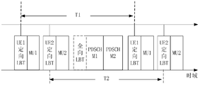
- FIG. 2E is another schematic diagram of sending periodic signals according to an embodiment of the application, as shown in FIG. 2E.
- the terminal device UE1 sends the first control signal MU1 to the terminal device according to the period T1
- the terminal device UE2 sends the first control signal MU2 to the terminal device according to the period T2, where T1 and T2 may be the same or different.
- the first spatial reception parameters obtained by UE1 and UE2 may be the same or different. That is, UE1 and UE2 may perform channel sensing in the same beam direction, or may perform channel sensing in different beam directions.
- the first control signal sent by the terminal device can pass the periodic PUCCH, semi-persistent scheduling PUSCH, scheduling-free PUSCH, configuration scheduling PUSCH, channel sounding reference signal (Sounding Reference Signal). Signal, SRS), or Physical Random Access Channel (PRACH) transmission.
- periodic PUCCH periodic Physical Uplink Control Channel
- semi-persistent scheduling PUSCH scheduling-free PUSCH
- configuration scheduling PUSCH configuration scheduling PUSCH
- channel sounding reference signal Sounding Reference Signal
- Signal SRS
- PRACH Physical Random Access Channel
- the terminal device periodically sends the first control signal to the network device, and at the same time periodically performs channel sensing before the first control signal, and can correspondingly receive the first downlink shared signal periodically, because The first control signal is scheduled by the upper layer control instruction and the third control signal. Therefore, this process reduces the number of times the network device needs to send scheduling signals or signaling for scheduling uplink and downlink resources, and improves communication efficiency.
- format 0/1 is a sequence, which means 1 bit of information, which can be used to send shorter signals, such as the send command in the above description, which only indicates “send” or “do not send”; or it can be the listening result, which means " Free” or “not free”.
- format 2/3 is a binary code of multiple bits, which can be used to send longer signals, such as interference detection results.
- format 2/3 can also include the remaining channel occupancy time (Channel Occupancy Time, COT).
- the terminal device recommends the offset of the PDSCH signal sent by the network device from the end of the PUCCH signal, the length, MCS, and the terminal device can receive Information such as the interference threshold for the base station can help the base station side adjust the subsequent transmission of PDSCH data signals.
- PUCCH format 2/3 can also carry other uplink control information (Uplink Control Information, UCI) information with high priority, such as Hybrid Automatic Repeat Request Acknowledge Character, HARQ-ACK) etc.
- UCI Uplink Control Information
- HARQ-ACK Hybrid Automatic Repeat Request Acknowledge Character
- the network device before using format 0/1 to send the first control signal, can pre-configure the same time-frequency resources for PUCCH1 of different terminal devices using format 0/1 through upper-layer signaling or protocol. , Then when the terminal device sends the first control signal, other terminal devices with the same time-frequency resource as the first control signal receive or detect the signal, stop sending the signal to the network device in the t1 time period.
- t1 can also be pre-configured by upper layer signaling or protocol.
- the network device Before format 2/3 is used to send the first control signal, the network device can pre-configure the same scrambling sequence and time-frequency resource for PUCCH1 of different terminal devices using format 2/3 through upper-layer signaling or protocol, then when the terminal device uses When format2/3 sends the first control signal, other terminal devices that have the same scrambling sequence as the first control signal receive or detect the signal, and stop sending the signal to the network device within the t2 time period. Wherein t2 can be carried by the first control signal.
- the network device sends the first downlink shared signal according to the first control signal.
- the network device after the network device receives the first control signal, it can determine whether to send or not send the first downlink shared signal according to the sending instruction therein, or determine whether to send or not send it according to the parameter information or instruction information therein.
- the first downlink shared signal That is, the network device performs a first downlink shared signal scheduling according to each first control signal.
- the spatial reception parameters for the terminal equipment to receive the first downlink shared signal are the same as the spatial reception parameters for the terminal equipment to perform channel sensing or channel interference detection, and both are the first spatial reception parameters.
- the network device may also schedule the first downlink shared signal according to the first cycle, or may randomly schedule the first downlink shared signal in a dynamic manner.
- the terminal device performs channel sensing or channel interference detection in the beam direction determined by the first spatial receiving parameter according to the first period.
- the first spatial receiving parameter corresponding to the signal of each period may be the same or different.
- the first spatial receiving parameter The determined beam direction may be a fixed beam direction, or may be a variable beam direction, for example, may be one or more beam directions with the highest strength of the signal received by the network device by the terminal device.
- channel sensing may also be performed to ensure that the channel meets the signal sending condition. That is, channel sensing is performed in the beam direction determined according to the second spatial receiving parameter.
- the beam width determined by the second spatial receiving parameter is the omnidirectional beam width.
- channel sensing in the beam direction determined by the second space receiving parameter is called omnidirectional LBT.
- the first preset value can be 16 ⁇ s (microseconds), 5 us, 9 us, etc.
- the first preset length may be 500 us. It means that the first downlink shared signal is a short signal, which has low interference to the channel, so the signal can be sent directly without performing omnidirectional LBT.
- omnidirectional LBT may also be performed before transmission, and when the signal length is less than or equal to the first preset length, the signal may be directly transmitted without performing omnidirectional LBT.
- the terminal device before the network device schedules the downlink shared signal, the terminal device prompts the network device to send the signal, so that the direction of the channel usage determined by the terminal device before receiving the downlink shared signal is the direction of receiving the downlink shared signal.
- Direction effectively reducing the problem of exposed nodes of terminal equipment (receiving nodes).
- FIG. 3A is a schematic flowchart of another signal transmission method according to an embodiment of the application. As shown in FIG. 3A, the method includes the following steps:
- a network device sends a fourth control signal to a terminal device, where the fourth control signal is used to instruct the terminal device to send a first uplink shared signal;
- the terminal device sends the first uplink shared signal according to the fourth control signal.
- DCI may include resource allocation of terminal equipment and other control information, such as control information for sending uplink shared signals, and time-frequency resources for sending uplink shared signals.
- the terminal device After receiving the DCI, the terminal device sends an uplink shared signal to the network device through the PUSCH corresponding to the time-frequency position.
- the process of invoking the uplink shared signal is also carried out by upper-layer control signaling, which specifically includes two methods: Method one, the network device configures uplink resources for the terminal device through the upper-layer control signaling, such as RRC, for the terminal device, such as the frequency of the uplink resource. Configuration information such as domain location, code word resources, MCS, maximum transmit power, etc., when the terminal device receives these configuration information, it can send the uplink shared signal on the corresponding resource. Method 2: After the network device configures the uplink resources for the terminal device, these uplink resources are not effective immediately, and DCI signaling needs to be used to activate these uplink resources, and then the terminal device sends an uplink shared signal on the corresponding resource. At this time, part of the signaling sent in RRC, such as MCS, is sent by DCI.
- RRC upper-layer control signaling
- the network device before the terminal device sends the first uplink sharing signal, the network device first sends a fourth control signal to the terminal device, which is used to instruct the terminal device to send the first uplink sharing signal.
- Figure 3C is a schematic diagram of a communication process based on network device channel sensing provided by an embodiment of the application.
- the fourth control signal PDCCH M2 is sent to the terminal device through the PDCCH.
- the PDCCH resources scheduled by the PDCCH M2 may be referred to as PDCCH schedule (schedule) B.
- the PDCCH M2 is used to prompt the node (terminal device) that receives the signal whether to send data.
- the PDCCH M2 may be a sending instruction, which is used to directly instruct the terminal device to send or not to send the first uplink shared signal PUSCH M1.
- the PDCCH M2 may be some parameter information or indication information, and the terminal device determines whether to send the first downlink shared signal according to the received parameter information or indication information.
- the PDCCH M2 may include indication information used to indicate the channel sensing result of the network device.
- the channel sensing result includes whether the channel is idle or not.
- the process for the network device to obtain the channel sensing result is: channel interference detection And obtain the interference detection result, the interference detection result can include the interference value, the signal interference source or the signal interference type, etc.
- the network device compares the interference value with a preset threshold (ED).
- ED preset threshold
- the setting of the ED can be determined according to the MCS of the first uplink shared signal, and the corresponding relationship between the MCS and the ED can refer to the specific description in the embodiment of step 201 to step 202.
- the setting of the ED can also be determined according to the receiving capability (Capability) of the network device.
- a network device with a strong receiving capability may use a higher ED corresponding to a network device with a lower receiving capability. If the interference value is less than or equal to ED, the channel listening result sent by the network device to the terminal device is idle, and the terminal device can send PUSCH M1 to the network device; if the interference value> ED, the channel listening result sent by the network device to the terminal device is If it is not idle, the terminal device cannot send PUSCH M1 to the network device.
- the setting of the ED can also be determined according to the interference source or the interference type. For example, the ED threshold used for the interference signal of the non-local cell may be higher than the ED threshold used for the interference signal from other cells.
- the network device determines that the interference value ⁇ ED according to the process of comparing the interference value with the preset threshold (ED), it directly generates the sending instruction as "sendable”, and after determining the interference value> ED, it directly generates the sending instruction as "Unsendable”.
- the terminal device determines whether to send PUSCH M1 according to the sending instruction.
- the fifth control signal PDCCH M3 may be sent to the terminal device, and the PDCCH resource scheduled by the PDCCH M1 may be called PDCCH schedule A.
- the PDCCH M3 may be used to instruct the terminal device to detect the resources of the PDCCH M2.
- the terminal equipment detects the PDCCH M2 on the time-frequency and code resources indicated by the resource. After receiving the PDCCH M2, if the terminal device determines to send the first uplink shared signal, it sends it in the beam direction determined by the receiving parameter in the third space, where the beam direction of the network device for channel sensing is the same as the beam receiving the first uplink shared signal The same direction.
- this process may be referred to as directed LBT.
- the beam direction for channel sensing or interference detection is the beam direction of the received signal, which reduces signal interference from other non-received signal directions. Effectively reduce the problem of network equipment exposing nodes.
- the terminal device sends the first uplink shared signal according to the fourth control signal.
- the terminal device after receiving the fourth control signal, the terminal device can directly determine whether to send or not send the first uplink shared signal according to the sending instruction therein, or determine whether to send or not send the first uplink shared signal according to the instruction information therein. Shared signal.
- omnidirectional channel sensing may also be performed to ensure that the signal sending condition is met.
- the omnidirectional operation may not be performed before the first uplink shared signal is sent.
- LBT sends the signal directly.
- the second preset value may be 16 ⁇ s (microseconds), 5 us or 9 us.
- the signal length of the first uplink shared signal is less than or equal to the second preset length, it means that the first uplink shared signal is a short signal, which has low requirements on channel interference, so it can be used directly without performing omnidirectional LBT.
- the second preset length may be 500us.
- the network device can perform channel sensing before transmitting to meet the signal transmission conditions, that is, perform channel sensing according to the beam direction determined by the fourth spatial receiving parameter, where the fourth spatial receiving parameter determines the beam
- the coverage area is larger than the beam coverage area determined by the third spatial receiving parameter.
- the beam coverage determined by the fourth spatial receiving parameter may be an omnidirectional beam coverage, then channel sensing in the beam direction determined by the fourth spatial receiving parameter is omnidirectional LBT, but when the signal length is less than or equal to the first When a preset length is used, the signal can be sent directly without performing omnidirectional LBT.
- the network device before the network device schedules the uplink shared signal, the network device prompts the terminal device to send the signal, so that the direction in which the network device performs channel sensing before receiving the uplink shared signal is the direction of receiving the uplink shared signal , Effectively reducing the problem of exposed nodes of network equipment (receiving nodes).
- Fig. 4 is a network device 400 provided by an embodiment of the application, which can be used to execute the signal transmission method and specific embodiments of the network device of Figs. 2A to 2E or Figs. 3A to 3C.
- the network device may be a network device.
- the device may also be a chip configured in a network device.
- the network device 400 includes a sending module 401 and a receiving module 402.
- the receiving module 401 is configured to receive a first control signal from a terminal device, where the first control signal is used to instruct the network device to send a first downlink shared signal;
- the sending module 402 is configured to send the first downlink shared signal according to the first control signal.
- the first control signal includes indication information used to indicate a channel usage status of the terminal device, and the channel usage status represents a detection result of the terminal device according to the first spatial reception parameter.
- the indication information includes a channel sensing result, and the channel sensing result includes a channel being idle or not, and the sending module 402 is specifically configured to send the first downlink shared signal when the channel is idle.
- the indication information includes a channel interference detection result
- the sending module 402 is specifically configured to: when the interference value corresponding to the channel interference detection result is less than a preset threshold, send the first downlink share Signal.
- the sending module 402 is further configured to send a second control signal, where the second control signal is used to instruct the terminal device to send the resource of the first control signal.
- the first control signal is a signal sent according to a first period, and the first period is a sending interval of the first control signal, and the sending module 402 is further configured to: instruct via upper layer control signaling The resource for sending the first control signal by the terminal device.
- the sending module 402 is further configured to send a third control signal, and activate the resource for sending the first control signal through the third control signal.
- the device further includes a processing module 403, configured to receive the parameter determined in the second space when the signal length of the second control signal or the first downlink shared signal is greater than a first preset length Channel sensing is performed in the beam direction of, and the beam width determined by the second spatial receiving parameter is an omnidirectional beam width.
- a processing module 403 configured to receive the parameter determined in the second space when the signal length of the second control signal or the first downlink shared signal is greater than a first preset length Channel sensing is performed in the beam direction of, and the beam width determined by the second spatial receiving parameter is an omnidirectional beam width.
- the processing module 403 is further configured to: when the time interval between the first control signal and the first downlink shared signal is greater than a first preset value, the beam direction determined according to the second spatial reception parameter Perform channel listening.
- the sending module 402 is configured to send a fourth control signal to a terminal device, where the fourth control signal is used to instruct the terminal device to send a first uplink shared signal;
- the receiving module 401 is configured to receive the first uplink shared signal sent according to the fourth control signal.
- the sending module 402 is further configured to send a fifth control signal, where the fifth control signal is used to instruct the terminal device to detect the resource of the fourth control signal.
- the device further includes a processing module 403, configured to use a third spatial receiving parameter for channel detection before the fourth control signal is sent to the terminal device, where the third spatial receiving parameter is the first The spatial reception parameters of the uplink shared signal.
- a processing module 403 configured to use a third spatial receiving parameter for channel detection before the fourth control signal is sent to the terminal device, where the third spatial receiving parameter is the first The spatial reception parameters of the uplink shared signal.
- the processing module 403 is further configured to, when the signal length of the second control signal is greater than the first preset length, perform channel sensing in the beam direction determined by the fourth spatial receiving parameter, and the fourth The beam coverage determined by the spatial receiving parameter is larger than the beam coverage determined by the third spatial receiving parameter.
- the foregoing receiving module 401 and sending module 402 may be interface circuits or transceivers.
- the receiving module 401 and the sending module 402 can be independent modules, or can be integrated as a transceiver module (not shown), and the transceiver module can implement the functions of the receiving module 401 and the sending module 402 described above.
- the above-mentioned processing module 403 may be a chip, an encoder, an encoding circuit or other integrated circuits that can implement the method of the present application.
- the network device 400 is used to execute the signal transmission method corresponding to the network device, so the specific description of the signal transmission method is involved, especially the functions of the receiving module 401 and the sending module 402 You can refer to the relevant part of the corresponding embodiment, which will not be repeated here.
- the network device 400 may also include a storage module (not shown in the figure).
- the storage module may be used to store data and/or signaling.
- the storage module may be coupled to the processing module 403, or may be coupled to the receiving module 401 or The sending module 402 is coupled.
- the processing module 403 may be used to read data and/or signaling in the storage module, so that the signal transmission method in the foregoing method embodiment is executed.
- FIG. 5 is a terminal device 500 provided by an embodiment of the present application, which may be used to execute the above-mentioned signal transmission method and specific embodiment of the terminal device of FIGS. 2A to 2E or FIGS. 3A to 3C.
- the terminal device may be The terminal device or the chip that can be configured in the terminal device.
- the terminal device 500 includes a receiving module 501, a sending module 502, and a processing module 503.
- the processing module 503 is configured to perform channel sensing. Specifically, the processing module 503 performs channel sensing according to the energy of the signal received by the receiving module 501;
- the sending module 502 is configured to send a first control signal to the network device when the channel is idle, and the first control signal is used to instruct the network device to send the first downlink shared signal;
- the receiving module 501 is configured to receive the first downlink shared signal from a network device.
- the processing module 503 is specifically configured to: perform channel sensing in the beam direction determined by the first spatial receiving parameter.
- the receiving module 501 is further configured to: receive a second control signal, and determine a resource for sending the first control signal according to the second control signal.
- the first control signal is a signal sent according to a first cycle
- the first cycle is a transmission interval of the first control signal
- the receiving module 501 is further configured to: Indicate determining the resource for sending the first control signal.
- the receiving module 501 is further configured to: receive a third control signal, and activate the resource for sending the first control signal through the third control signal.
- the receiving module 501 is configured to receive a fourth control signal sent by a network device, where the fourth control signal is used to instruct the terminal device to send a first uplink shared signal;
- the sending module 502 is configured to send a first uplink shared signal to the network device according to the fourth control signal.
- the receiving module 501 is further configured to: receive a fifth control signal, and determine a resource for detecting the fourth control signal according to the fifth control signal.
- the processing module 503 is configured to, when the signal length of the first uplink shared signal is greater than the second preset length, perform channel sensing in the beam direction determined by the fourth space receiving parameter, and when the channel is idle Sending the first uplink shared signal.
- the processing module 503 is configured to, when the time interval between the fourth control signal and the first uplink shared signal is greater than a second preset value, perform channel channeling in the beam direction determined by the fourth spatial receiving parameter Listen, and send the first uplink shared signal when the channel is idle.
- the receiving module 501 and the sending module 502 may be interface circuits or transceivers.
- the receiving module 501 and the sending module 502 can be independent modules, or can be integrated as a transceiver module (not shown in the figure), and the transceiver module can implement the functions of the receiving module 501 and the sending module 502 described above.
- the processing module 503 may be a chip, an encoder, an encoding circuit or other integrated circuits that can implement the method of the present application.
- the terminal device 500 is used to execute the signal transmission method corresponding to the terminal device, so the specific description of the signal transmission method is involved, including the receiving module 501, the sending module 502, and the processing module.
- the function of 503 please refer to the relevant part of the corresponding embodiment, which will not be repeated here.
- the terminal device 500 may also include a storage module (not shown in the figure).
- the storage module may be used to store data and/or signaling.
- the storage module may be coupled to the processing module 503, or may be coupled to the receiving module 501 or The sending module 502 is coupled.
- the processing module 503 may be used to read data and/or signaling in the storage module, so that the signal transmission method in the foregoing method embodiment is executed.
- FIG. 6 shows a schematic diagram of the hardware structure of a communication device in an embodiment of the present application.
- the structure of the transmitting end device and the receiving end device can refer to the structure shown in FIG. 6.
- the communication device 600 includes: a processor 111 and a communication transceiver 112, and the processor 111 and the transceiver 112 are electrically coupled;
- the processor 111 is configured to execute part or all of the computer program instructions in the memory, and when the part or all of the computer program instructions are executed, the device executes the method described in any of the foregoing embodiments.
- the transceiver 112 is used to communicate with other devices; for example, receiving a first uplink control signal from a terminal device, where the first uplink control signal is used to instruct the network device to send a first downlink shared signal; An uplink control signal sends the first downlink shared signal.
- the memory 113 for storing computer program instructions.
- the memory 113 (Memory#1) is located in the device, and the memory 113 (Memory#2) is integrated with the processor 111. Together, or the memory 113 (Memory#3) is located outside the device.
- the communication device 600 shown in FIG. 6 may be a chip or a circuit.
- a chip or circuit may be provided in a terminal device or a communication device.
- the aforementioned transceiver 112 may also be a communication interface.
- the transceiver includes a receiver and a transmitter.
- the communication device 600 may also include a bus system.
- the processor 111, the memory 113, and the transceiver 112 are connected by a bus system.
- the processor 111 is used to execute the instructions stored in the memory 113 to control the transceiver to receive signals and send signals to complete the first implementation method involved in this application.
- the memory 113 may be integrated in the processor 111, or may be provided separately from the processor 111.
- the function of the transceiver 112 may be implemented by a transceiver circuit or a dedicated transceiver chip.
- the processor 111 may be implemented by a dedicated processing chip, a processing circuit, a processor, or a general-purpose chip.
- the processor may be a central processing unit (CPU), a network processor (NP), or a combination of CPU and NP.
- the processor may further include a hardware chip or other general-purpose processors.
- the above-mentioned hardware chip may be an application-specific integrated circuit (ASIC), a programmable logic device (PLD) or a combination thereof.
- ASIC application-specific integrated circuit
- PLD programmable logic device
- the above-mentioned PLD can be a complex programmable logic device (CPLD), a field-programmable gate array (FPGA), a general array logic (generic array logic, GAL) and other programmable logic devices , Discrete gates or transistor logic devices, discrete hardware components, etc. or any combination thereof.
- the general-purpose processor may be a microprocessor or the processor may also be any conventional processor or the like.
- the memory mentioned in the embodiments of the present application may be a volatile memory or a non-volatile memory, or may include both volatile and non-volatile memory.
- the non-volatile memory can be read-only memory (Read-Only Memory, ROM), programmable read-only memory (Programmable ROM, PROM), erasable programmable read-only memory (Erasable PROM, EPROM), and electrically available Erase programmable read-only memory (Electrically EPROM, EEPROM) or flash memory.
- the volatile memory may be a random access memory (Random Access Memory, RAM), which is used as an external cache.
- RAM random access memory
- SRAM static random access memory
- DRAM dynamic random access memory
- DRAM synchronous dynamic random access memory
- DDR SDRAM Double Data Rate Synchronous Dynamic Random Access Memory
- Enhanced SDRAM, ESDRAM Enhanced Synchronous Dynamic Random Access Memory
- Synchronous Link Dynamic Random Access Memory Synchronous Link Dynamic Random Access Memory
- DR RAM Direct Rambus RAM
- FIG. 7 is a communication system 900 provided by an embodiment of the application, which includes a terminal device 901 and a network device 902.
- the terminal device 901 may include the terminal device 500 described in FIG. 5, and the network device 902 may Including the network device 400 as shown in FIG. 4, the hardware structure corresponding to the terminal device 901 and the network device 902 may be the communication device 600 as shown in FIG.
- the communication system 900 can be used to execute the aforementioned communication methods and specific embodiments applicable to the aforementioned terminal devices and network devices. For the specific execution process, refer to the description content of FIGS. 2A to 2E or FIGS. 3A to 3C.
- the embodiment of the present application provides a computer storage medium that stores a computer program, and the computer program includes a method for executing a corresponding method for a network device in the foregoing embodiment.
- the embodiment of the present application provides a computer storage medium that stores a computer program, and the computer program includes a method for executing a corresponding method for a network device in the foregoing embodiment.
- the embodiments of the present application provide a computer program product containing instructions, which when run on a computer, cause the computer to execute the method corresponding to the terminal device in the foregoing embodiment.
- the embodiments of the present application provide a computer program product containing instructions, which when run on a computer, cause the computer to execute the method corresponding to the terminal device in the foregoing embodiment.
- the size of the sequence number of the above-mentioned processes does not mean the order of execution, and the execution order of each process should be determined by its function and internal logic, and should not correspond to the embodiments of the present application.
- the implementation process constitutes any limitation.
- the disclosed system, device, and method can be implemented in other ways.
- the device embodiments described above are only illustrative.
- the division of the units is only a logical function division, and there may be other divisions in actual implementation, for example, multiple units or components may be combined or It can be integrated into another system, or some features can be ignored or not implemented.
- the displayed or discussed mutual coupling or direct coupling or communication connection may be indirect coupling or communication connection through some interfaces, devices or units, and may be in electrical, mechanical or other forms.
- the units described as separate components may or may not be physically separated, and the components displayed as units may or may not be physical units, that is, they may be located in one place, or they may be distributed on multiple network units. Some or all of the units may be selected according to actual needs to achieve the objectives of the solutions of the embodiments.
- the functional units in the various embodiments of the present application may be integrated into one processing unit, or each unit may exist alone physically, or two or more units may be integrated into one unit.
- the function is implemented in the form of a software functional unit and sold or used as an independent product, it can be stored in a computer readable storage medium.
- the technical solution of the present application essentially or the part that contributes to the existing technology or the part of the technical solution can be embodied in the form of a software product, and the computer software product is stored in a storage medium, including Several instructions are used to make a computer device (which may be a personal computer, a server, or a network device, etc.) execute all or part of the steps of the methods described in the various embodiments of the present application.
- the aforementioned storage media include: U disk, mobile hard disk, read-only memory (Read-Only Memory, ROM), random access memory (Random Access Memory, RAM), magnetic disks or optical disks and other media that can store program codes. .
Landscapes
- Engineering & Computer Science (AREA)
- Computer Networks & Wireless Communication (AREA)
- Signal Processing (AREA)
- Mobile Radio Communication Systems (AREA)
Abstract
Description
| MCS | ED |
| mcs0 | -26dbm |
| mcs1 | -28dbm |
| mcs2 | -30dbm |
| mcs3 | -32dbm |
| … | … |

Claims (41)
- 一种信号传输方法,其特征在于,应用于网络设备,所述方法包括:接收来自终端设备的第一控制信号,所述第一控制信号用于网络设备确定是否发送第一下行共享信号;根据所述第一控制信号发送所述第一下行共享信号。
- 根据权利要求1所述的方法,其特征在于,所述第一控制信号中包括用于指示所述终端设备的信道使用情况的指示信息,所述信道使用情况表示终端设备根据第一空间接收参数进行检测的结果。
- 根据权利要求2所述的方法,其特征在于,所述指示信息包括信道侦听结果,所述信道侦听结果包括信道空闲或不空闲,所述根据所述第一控制信号发送所述第一下行共享信号包括:当信道空闲时发送所述第一下行共享信号。
- 根据权利要求2所述的方法,其特征在于,所述指示信息包括信道干扰检测结果,所述根据所述第一控制信号发送所述第一下行共享信号包括:当所述信道干扰检测结果对应的干扰值小于预设门限值时,发送所述第一下行共享信号。
- 根据权利要求1-4任一项所述的方法,其特征在于,在所述接收来自终端设备的第一控制信号之前,所述方法还包括:发送第二控制信号,所述第二控制信号用于指示所述终端设备发送所述第一控制信号的资源。
- 根据权利要求5所述的方法,其特征在于,所述第二控制信号中还包括传输配置指示,所述传输配置指示用于所述终端设备确定第一空间接收参数,所述第一空间接收参数与发送所述第一下行共享信号的空间接收参数一致。
- 根据权利要求1-4任一项所述的方法,其特征在于,所述第一控制信号为按照第一周期发送的信号,所述第一周期为所述第一控制信号的发送间隔,在所述接收来自终端设备的第一控制信号之前,所述方法还包括:通过上层控制信令指示所述终端设备发送所述第一控制信号的资源。
- 根据权利要求7所述的方法,其特征在于,所述通过上层控制信令指示所述终端设备发送所述第一控制信号的资源还包括:发送第三控制信号,通过所述第三控制信号激活所述发送所述第一控制信号的资源。
- 根据权利要求7或8所述的方法,其特征在于,所述上层控制信令或所述第三控制信号中还包括传输配置指示,所述传输配置指示用于所述终端设备确定第一空间接收参数,所述第一空间接收参数与发送所述第一下行共享信号的空间接收参数一致。
- 根据权利要求9所述的方法,其特征在于,当所述第一控制信号为按照第一周期发送的信号时,每个周期的信号所对应的第一空间接收参数不同。
- 根据权利要求7-10任一项所述的方法,其特征在于,所述第一控制信号通过周期性的物理上行控制信道PUCCH,半静态调度物理上行共享信道PUSCH,免调度PUSCH,配置调度PUSCH,信道探测参考信号SRS,或物理随机接入信道PRACH发送。
- 根据权利要求5-11任一项所述的方法,其特征在于,当所述第二控制信号、或所述第一下行共享信号的信号长度大于第一预设长度时,在第二空间接收参数所确定的波束方向进行信道侦听,所述第二空间接收参数确定的波束宽度为全向波束宽度。
- 根据权利要求1-12任一项所述的方法,其特征在于,当所述第一控制信号与所述第一下行共享信号的时间间隔大于第一预设值时,根据第二空间接收参数确定的波束方向进行信道侦听。
- 一种信号传输方法,其特征在于,应用于网络设备,所述方法包括:向终端设备发送第四控制信号,所述第四控制信号用于指示所述终端设备发送第一上行共享信号;接收所述终端设备根据所述第四控制信号发送的所述第一上行共享信号。
- 根据权利要求14所述的方法,其特征在于,在所述发送第四控制信号之前,所述方法还包括:发送第五控制信号,所述第五控制信号用于指示所述终端设备检测所述第四控制信号的资源。
- 根据权利要求14或15所述的方法,其特征在于,在所述向终端设备发送第四控制信号之前,采用第三空间接收参数进行信道检测,所述第三空间接收参数为所述第一上行共享信号的空间接收参数。
- 根据权利要求15或16所述的方法,其特征在于,当所述第五控制信号的信号长度大于第二预设长度时,在第四空间接收参数确定的波束方向进行信道侦听,所述第四空间接收参数确定的波束覆盖范围大于所述第三空间接收参数确定的波束覆盖范围。
- 一种信号传输方法,其特征在于,应用于终端设备,所述方法包括:进行信道侦听,并在信道空闲时向网络设备发送第一控制信号,所述第一控制信号用于指示网络设备发送第一下行共享信号;接收来自网络设备的所述第一下行共享信号。
- 根据权利要求18所述的方法,其特征在于,所述进行信道侦听包括:在第一空间接收参数确定的波束方向进行信道侦听。
- 根据权利要求19所述的方法,其特征在于,所述第一控制信号中包括用于指示所述终端设备的信道使用情况的指示信息,所述信道使用情况表示所述终端设备根据所述第一空间接收参数进行检测的结果。
- 根据权利要求18-20任一项所述的方法,其特征在于,在所述进行信道侦听,并在信道空闲时向网络设备发送第一控制信号之前,所述方法还包括:接收第二控制信号,根据所述第二控制信号确定发送所述第一控制信号的资源。
- 根据权利要求21所述的方法,其特征在于,所述第二控制信号中还包括传输配置指示,所述传输配置指示用于确定第一空间接收参数,所述第一空间接收参数与接收所述第一下行共享信号的空间接收参数一致。
- 根据权利要求18-20任一项所述的方法,其特征在于,所述第一控制信号为按照 第一周期发送的信号,所述第一周期为所述第一控制信号的发送间隔,在所述进行信道侦听,并在信道空闲时向网络设备发送第一控制信号之前,所述方法还包括:通过上层控制信令的指示确定发送所述第一控制信号的资源。
- 根据权利要求23所述的方法,其特征在于,所述通过上层控制信令的指示确定发送所述第一控制信号的资源还包括:接收第三控制信号,通过所述第三控制信号激活发送所述第一控制信号的资源。
- 根据权利要求23或24所述的方法,其特征在于,所述上层控制信令或所述第三控制信号中还包括传输配置指示,所述传输配置指示用于确定第一空间接收参数,所述第一空间接收参数与接收所述第一下行共享信号的空间接收参数一致。
- 根据权利要求25所述的方法,其特征在于,当所述第一控制信号为按照第一周期发送的信号时,每个周期的信号所对应的第一空间接收参数不同。
- 根据权利要求20-26任一项所述的方法,其特征在于,所述第一控制信号的格式为format 0/1。
- 根据权利要求20-26任一项所述的方法,其特征在于,所述第一控制信号的格式为format 2/3,所述format2/3采用第一扰码加扰,所述第一扰码用于另一终端设备解调所述第一控制信号。
- 一种信号传输方法,其特征在于,应用于终端设备,所述方法包括:接收网络设备发送的第四控制信号,所述第四控制信号用于指示所述终端设备发送第一上行共享信号;根据所述第四控制信号向所述网络设备发送第一上行共享信号。
- 根据权利要求29所述的方法,其特征在于,在接收所述第四控制信号之前,所述方法还包括:接收第五控制信号,根据所述第五控制信号确定检测所述第四控制信号的资源。
- 根据权利要求29或30所述的方法,其特征在于,当所述第一上行共享信号的信号长度大于第二预设长度时,在第四空间接收参数确定的波束方向进行信道侦听,当信道空闲时发送所述第一上行共享信号。
- 根据权利要求29或30所述的方法,其特征在于,当所述第四控制信号与所述第一上行共享信号的时间间隔大于第二预设值时,在第四空间接收参数确定的波束方向进行信道侦听,当信道空闲时发送所述第一上行共享信号。
- 一种网络设备,其特征在于,所述网络设备包括:接收模块,用于接收来自终端设备的第一控制信号,所述第一控制信号用于网络设备确定是否发送第一下行共享信号;发送模块,用于根据所述第一控制信号发送所述第一下行共享信号。
- 一种网络设备,其特征在于,所述网络设备包括:发送模块,用于向终端设备发送第四控制信号,所述第四控制信号用于指示所述终端 设备发送第一上行共享信号;接收模块,用于接收根据所述第四控制信号发送的所述第一上行共享信号。
- 一种终端设备,其特征在于,所述设备包括:处理模块,用于进行信道侦听;发送模块,用于在信道空闲时向网络设备发送第一控制信号,所述第一控制信号用于指示网络设备发送第一下行共享信号;接收模块,用于接收来自网络设备的所述第一下行共享信号。
- 一种终端设备,其特征在于,所述设备包括:接收模块,用于接收网络设备发送的第四控制信号,所述第四控制信号用于指示所述终端设备发送第一上行共享信号;发送模块,用于根据所述第四控制信号向所述网络设备发送第一上行共享信号。
- 一种通信装置,其特征在于,所述装置包括至少一个处理器,所述至少一个处理器与至少一个存储器耦合:所述至少一个处理器,用于执行所述至少一个存储器中存储的计算机程序或指令,以使得所述装置执行如权利要求1-13或14-17中任一项所述的方法。
- 一种通信装置,其特征在于,所述装置包括至少一个处理器,所述至少一个处理器与至少一个存储器耦合:所述至少一个处理器,用于执行所述至少一个存储器中存储的计算机程序或指令,以使得所述装置执行如权利要求18-28或29-32中任一项所述的方法。
- 一种可读存储介质,其特征在于,用于存储指令,当所述指令被执行时,使如权利要求1-13或14-17中任一项所述的方法被实现,或者使如权利要18-28或29-32中任一项所述的方法被实现。
- 一种计算机程序产品,当计算机读取并执行所述计算机程序产品时,使得计算机执行如权利要求1-13或14-17中所述的方法,或者使计算机执行如权利要求18-28或29-32中所述的方法。
- 一种通信系统,包括如权利要求33中所述的网络设备和权利要求35中所述的终端设备,或者如权利要求34中所述的网络设备和权利要求36中所述的终端设备。
Priority Applications (5)
| Application Number | Priority Date | Filing Date | Title |
|---|---|---|---|
| EP20919973.6A EP4096286A4 (en) | 2020-02-21 | 2020-02-21 | SIGNAL TRANSMISSION METHOD AND DEVICE |
| CN202080096250.3A CN115066926B (zh) | 2020-02-21 | 2020-02-21 | 信号传输方法及装置 |
| PCT/CN2020/076284 WO2021164035A1 (zh) | 2020-02-21 | 2020-02-21 | 信号传输方法及装置 |
| CA3168746A CA3168746A1 (en) | 2020-02-21 | 2020-02-21 | Signal transmission method and apparatus |
| US17/821,040 US20220394684A1 (en) | 2020-02-21 | 2022-08-19 | Signal Transmission Method and Apparatus |
Applications Claiming Priority (1)
| Application Number | Priority Date | Filing Date | Title |
|---|---|---|---|
| PCT/CN2020/076284 WO2021164035A1 (zh) | 2020-02-21 | 2020-02-21 | 信号传输方法及装置 |
Related Child Applications (1)
| Application Number | Title | Priority Date | Filing Date |
|---|---|---|---|
| US17/821,040 Continuation US20220394684A1 (en) | 2020-02-21 | 2022-08-19 | Signal Transmission Method and Apparatus |
Publications (1)
| Publication Number | Publication Date |
|---|---|
| WO2021164035A1 true WO2021164035A1 (zh) | 2021-08-26 |
Family
ID=77390386
Family Applications (1)
| Application Number | Title | Priority Date | Filing Date |
|---|---|---|---|
| PCT/CN2020/076284 Ceased WO2021164035A1 (zh) | 2020-02-21 | 2020-02-21 | 信号传输方法及装置 |
Country Status (5)
| Country | Link |
|---|---|
| US (1) | US20220394684A1 (zh) |
| EP (1) | EP4096286A4 (zh) |
| CN (1) | CN115066926B (zh) |
| CA (1) | CA3168746A1 (zh) |
| WO (1) | WO2021164035A1 (zh) |
Cited By (1)
| Publication number | Priority date | Publication date | Assignee | Title |
|---|---|---|---|---|
| WO2023130480A1 (zh) * | 2022-01-10 | 2023-07-13 | Oppo广东移动通信有限公司 | 无线通信方法、装置、设备、存储介质及程序产品 |
Families Citing this family (5)
| Publication number | Priority date | Publication date | Assignee | Title |
|---|---|---|---|---|
| CN115669046A (zh) * | 2020-05-22 | 2023-01-31 | 株式会社Ntt都科摩 | 发送设备、接收设备、干扰信息发送方法和信道接入方法 |
| CN115835406B (zh) * | 2020-06-12 | 2024-10-18 | Oppo广东移动通信有限公司 | 无线通信的方法及设备 |
| CN117322119A (zh) * | 2021-05-21 | 2023-12-29 | 株式会社Ntt都科摩 | 终端以及通信方法 |
| US20240334425A1 (en) * | 2023-03-29 | 2024-10-03 | Qualcomm Incorporated | Techniques for random access channel resource selection for sub-band full duplex |
| WO2025129661A1 (zh) * | 2023-12-22 | 2025-06-26 | 北京小米移动软件有限公司 | 通信方法及装置、存储介质 |
Citations (4)
| Publication number | Priority date | Publication date | Assignee | Title |
|---|---|---|---|---|
| CN104247498A (zh) * | 2013-04-23 | 2014-12-24 | 华为技术有限公司 | 一种数据包传输的方法和设备 |
| CN105101435A (zh) * | 2015-07-29 | 2015-11-25 | 魅族科技(中国)有限公司 | 数据传输的方法和设备 |
| WO2018045586A1 (zh) * | 2016-09-12 | 2018-03-15 | 广东欧珀移动通信有限公司 | 导频信号的传输方法和设备 |
| WO2019051804A1 (zh) * | 2017-09-15 | 2019-03-21 | Oppo广东移动通信有限公司 | 传输数据的方法、终端设备和网络设备 |
Family Cites Families (12)
| Publication number | Priority date | Publication date | Assignee | Title |
|---|---|---|---|---|
| KR102049772B1 (ko) * | 2013-01-15 | 2019-11-28 | 삼성전자 주식회사 | 빔포밍 시스템에서 신호 측정 방법 및 장치 |
| US11102815B2 (en) * | 2017-10-02 | 2021-08-24 | Qualcomm Incorporated | Asynchronous spatial LBT |
| CN110034832B (zh) * | 2018-01-12 | 2020-08-07 | 华为技术有限公司 | 监控信道质量的方法和终端设备 |
| US10912128B2 (en) * | 2018-01-23 | 2021-02-02 | Samsung Electronics Co., Ltd. | Listen-before-talk for wideband operations of NR unlicensed spectrum |
| WO2019160741A1 (en) * | 2018-02-14 | 2019-08-22 | Idac Holdings, Inc. | Methods, apparatus, and system using multiple antenna techniques for new radio (nr) operations in unlicensed bands |
| US20190297603A1 (en) * | 2018-03-23 | 2019-09-26 | Samsung Electronics Co., Ltd. | Method and apparatus for beam management for multi-stream transmission |
| CN110351851B (zh) * | 2018-04-04 | 2023-08-25 | 华为技术有限公司 | 数据传输方法、终端设备和网络设备 |
| CN110536432B (zh) * | 2018-09-21 | 2025-07-22 | 中兴通讯股份有限公司 | 一种信息传输的方法、装置和设备 |
| DE102019202725A1 (de) * | 2019-02-28 | 2020-09-03 | Diehl Metering Gmbh | Signalisierung einer multicast-nachricht in nicht koordinierten netzen |
| US12452698B2 (en) * | 2019-03-28 | 2025-10-21 | Telefonaktiebolaget Lm Ericsson (Publ) | Collection and reporting of channel occupancy statistics for network tuning |
| US11272375B2 (en) * | 2019-04-15 | 2022-03-08 | Government Of The United States Of America, As Represented By The Secretary Of Commerce | Dynamic physical resource block control apparatus and process for dynamically controlling allocation of a physical resource block |
| CN115211218A (zh) * | 2020-02-12 | 2022-10-18 | Idac控股公司 | 未许可频谱中的信道接入 |
-
2020
- 2020-02-21 WO PCT/CN2020/076284 patent/WO2021164035A1/zh not_active Ceased
- 2020-02-21 CA CA3168746A patent/CA3168746A1/en active Pending
- 2020-02-21 EP EP20919973.6A patent/EP4096286A4/en active Pending
- 2020-02-21 CN CN202080096250.3A patent/CN115066926B/zh active Active
-
2022
- 2022-08-19 US US17/821,040 patent/US20220394684A1/en not_active Abandoned
Patent Citations (5)
| Publication number | Priority date | Publication date | Assignee | Title |
|---|---|---|---|---|
| CN104247498A (zh) * | 2013-04-23 | 2014-12-24 | 华为技术有限公司 | 一种数据包传输的方法和设备 |
| CN109219005A (zh) * | 2013-04-23 | 2019-01-15 | 华为技术有限公司 | 一种数据包传输的方法和设备 |
| CN105101435A (zh) * | 2015-07-29 | 2015-11-25 | 魅族科技(中国)有限公司 | 数据传输的方法和设备 |
| WO2018045586A1 (zh) * | 2016-09-12 | 2018-03-15 | 广东欧珀移动通信有限公司 | 导频信号的传输方法和设备 |
| WO2019051804A1 (zh) * | 2017-09-15 | 2019-03-21 | Oppo广东移动通信有限公司 | 传输数据的方法、终端设备和网络设备 |
Non-Patent Citations (2)
| Title |
|---|
| HUAWEI ET AL: "HARQ enhancements in NR unlicensed", 3GPP DRAFT; R1-1812196, 3RD GENERATION PARTNERSHIP PROJECT (3GPP), MOBILE COMPETENCE CENTRE ; 650, ROUTE DES LUCIOLES ; F-06921 SOPHIA-ANTIPOLIS CEDEX ; FRANCE, 16 November 2018 (2018-11-16), Mobile Competence Centre ; 650, route des Lucioles ; F-06921 Sophia-Antipolis Cedex ; France, pages 1 - 13, XP051478352 * |
| See also references of EP4096286A4 * |
Cited By (1)
| Publication number | Priority date | Publication date | Assignee | Title |
|---|---|---|---|---|
| WO2023130480A1 (zh) * | 2022-01-10 | 2023-07-13 | Oppo广东移动通信有限公司 | 无线通信方法、装置、设备、存储介质及程序产品 |
Also Published As
| Publication number | Publication date |
|---|---|
| EP4096286A4 (en) | 2023-01-11 |
| US20220394684A1 (en) | 2022-12-08 |
| CN115066926B (zh) | 2025-04-22 |
| CA3168746A1 (en) | 2021-08-26 |
| EP4096286A1 (en) | 2022-11-30 |
| CN115066926A (zh) | 2022-09-16 |
Similar Documents
| Publication | Publication Date | Title |
|---|---|---|
| CN115066926B (zh) | 信号传输方法及装置 | |
| CN113783663B (zh) | 传输信息的方法、终端设备和网络设备 | |
| EP4027738B1 (en) | Communication method and apparatus | |
| US20220078823A1 (en) | Communication method and communication apparatus | |
| WO2023274012A1 (zh) | 侧行链路反馈信息传输的方法和通信装置 | |
| CN113424621B (zh) | 上报csi的方法和终端设备 | |
| EP3694249B1 (en) | Method for transmitting data, terminal device and network device | |
| US12089260B2 (en) | Random access method, terminal device and network device | |
| CN109413744B (zh) | 通信方法与设备 | |
| WO2020042123A1 (zh) | 发送上行信号的方法和设备 | |
| CN116017751B (zh) | 随机接入方法和通信装置 | |
| CN104380645A (zh) | 灵活的harq ack/nack传输 | |
| WO2020211096A1 (zh) | 无线通信方法、终端设备和网络设备 | |
| WO2019213971A1 (zh) | 上行信号的发送方法和终端设备 | |
| WO2020029199A1 (zh) | 传输信息的方法、终端设备和网络设备 | |
| WO2021087955A1 (zh) | 功率分配方法以及装置 | |
| WO2022077396A1 (zh) | 一种上行控制信息的发送方法、接收方法及通信装置 | |
| CN110891311A (zh) | 反馈信息传输的方法和通信装置 | |
| WO2022247918A1 (zh) | 发送、接收数据的方法、资源指示方法、装置及系统 | |
| WO2018171725A1 (zh) | 上行通信的方法、终端设备和网络设备 | |
| WO2019192500A1 (zh) | 通信方法和通信装置 | |
| US20230198595A1 (en) | Csi reporting method, csi receiving method, and corresponding apparatus | |
| CN114745793B (zh) | 传输数据的方法、网络设备和终端设备 | |
| WO2020051767A1 (zh) | 传输信息、接收信息的方法和通信设备 | |
| CN112438029B (zh) | 反馈信息的方法、终端、芯片和存储介质 |
Legal Events
| Date | Code | Title | Description |
|---|---|---|---|
| 121 | Ep: the epo has been informed by wipo that ep was designated in this application |
Ref document number: 20919973 Country of ref document: EP Kind code of ref document: A1 |
|
| ENP | Entry into the national phase |
Ref document number: 3168746 Country of ref document: CA |
|
| ENP | Entry into the national phase |
Ref document number: 2020919973 Country of ref document: EP Effective date: 20220826 |
|
| NENP | Non-entry into the national phase |
Ref country code: DE |
|
| WWG | Wipo information: grant in national office |
Ref document number: 202080096250.3 Country of ref document: CN |