WO2021166310A1 - 光反応評価装置およびフォトン数算出方法 - Google Patents
光反応評価装置およびフォトン数算出方法 Download PDFInfo
- Publication number
- WO2021166310A1 WO2021166310A1 PCT/JP2020/036556 JP2020036556W WO2021166310A1 WO 2021166310 A1 WO2021166310 A1 WO 2021166310A1 JP 2020036556 W JP2020036556 W JP 2020036556W WO 2021166310 A1 WO2021166310 A1 WO 2021166310A1
- Authority
- WO
- WIPO (PCT)
- Prior art keywords
- light source
- light
- intensity distribution
- irradiation
- sample
- Prior art date
- Legal status (The legal status is an assumption and is not a legal conclusion. Google has not performed a legal analysis and makes no representation as to the accuracy of the status listed.)
- Ceased
Links
Images





Classifications
-
- G—PHYSICS
- G01—MEASURING; TESTING
- G01N—INVESTIGATING OR ANALYSING MATERIALS BY DETERMINING THEIR CHEMICAL OR PHYSICAL PROPERTIES
- G01N21/00—Investigating or analysing materials by the use of optical means, i.e. using sub-millimetre waves, infrared, visible or ultraviolet light
- G01N21/17—Systems in which incident light is modified in accordance with the properties of the material investigated
- G01N21/25—Colour; Spectral properties, i.e. comparison of effect of material on the light at two or more different wavelengths or wavelength bands
- G01N21/31—Investigating relative effect of material at wavelengths characteristic of specific elements or molecules, e.g. atomic absorption spectrometry
-
- G—PHYSICS
- G01—MEASURING; TESTING
- G01N—INVESTIGATING OR ANALYSING MATERIALS BY DETERMINING THEIR CHEMICAL OR PHYSICAL PROPERTIES
- G01N21/00—Investigating or analysing materials by the use of optical means, i.e. using sub-millimetre waves, infrared, visible or ultraviolet light
- G01N21/17—Systems in which incident light is modified in accordance with the properties of the material investigated
- G01N21/25—Colour; Spectral properties, i.e. comparison of effect of material on the light at two or more different wavelengths or wavelength bands
- G01N21/27—Colour; Spectral properties, i.e. comparison of effect of material on the light at two or more different wavelengths or wavelength bands using photo-electric detection ; circuits for computing concentration
-
- G—PHYSICS
- G01—MEASURING; TESTING
- G01N—INVESTIGATING OR ANALYSING MATERIALS BY DETERMINING THEIR CHEMICAL OR PHYSICAL PROPERTIES
- G01N21/00—Investigating or analysing materials by the use of optical means, i.e. using sub-millimetre waves, infrared, visible or ultraviolet light
- G01N21/17—Systems in which incident light is modified in accordance with the properties of the material investigated
- G01N21/25—Colour; Spectral properties, i.e. comparison of effect of material on the light at two or more different wavelengths or wavelength bands
- G01N21/27—Colour; Spectral properties, i.e. comparison of effect of material on the light at two or more different wavelengths or wavelength bands using photo-electric detection ; circuits for computing concentration
- G01N21/274—Calibration, base line adjustment, drift correction
-
- G—PHYSICS
- G01—MEASURING; TESTING
- G01J—MEASUREMENT OF INTENSITY, VELOCITY, SPECTRAL CONTENT, POLARISATION, PHASE OR PULSE CHARACTERISTICS OF INFRARED, VISIBLE OR ULTRAVIOLET LIGHT; COLORIMETRY; RADIATION PYROMETRY
- G01J3/00—Spectrometry; Spectrophotometry; Monochromators; Measuring colours
- G01J3/28—Investigating the spectrum
-
- G—PHYSICS
- G01—MEASURING; TESTING
- G01J—MEASUREMENT OF INTENSITY, VELOCITY, SPECTRAL CONTENT, POLARISATION, PHASE OR PULSE CHARACTERISTICS OF INFRARED, VISIBLE OR ULTRAVIOLET LIGHT; COLORIMETRY; RADIATION PYROMETRY
- G01J3/00—Spectrometry; Spectrophotometry; Monochromators; Measuring colours
- G01J3/28—Investigating the spectrum
- G01J3/42—Absorption spectrometry; Double beam spectrometry; Flicker spectrometry; Reflection spectrometry
-
- G—PHYSICS
- G01—MEASURING; TESTING
- G01N—INVESTIGATING OR ANALYSING MATERIALS BY DETERMINING THEIR CHEMICAL OR PHYSICAL PROPERTIES
- G01N21/00—Investigating or analysing materials by the use of optical means, i.e. using sub-millimetre waves, infrared, visible or ultraviolet light
- G01N21/17—Systems in which incident light is modified in accordance with the properties of the material investigated
- G01N21/25—Colour; Spectral properties, i.e. comparison of effect of material on the light at two or more different wavelengths or wavelength bands
- G01N21/255—Details, e.g. use of specially adapted sources, lighting or optical systems
-
- G—PHYSICS
- G01—MEASURING; TESTING
- G01N—INVESTIGATING OR ANALYSING MATERIALS BY DETERMINING THEIR CHEMICAL OR PHYSICAL PROPERTIES
- G01N21/00—Investigating or analysing materials by the use of optical means, i.e. using sub-millimetre waves, infrared, visible or ultraviolet light
- G01N21/17—Systems in which incident light is modified in accordance with the properties of the material investigated
- G01N21/25—Colour; Spectral properties, i.e. comparison of effect of material on the light at two or more different wavelengths or wavelength bands
- G01N21/31—Investigating relative effect of material at wavelengths characteristic of specific elements or molecules, e.g. atomic absorption spectrometry
- G01N21/314—Investigating relative effect of material at wavelengths characteristic of specific elements or molecules, e.g. atomic absorption spectrometry with comparison of measurements at specific and non-specific wavelengths
-
- G—PHYSICS
- G01—MEASURING; TESTING
- G01N—INVESTIGATING OR ANALYSING MATERIALS BY DETERMINING THEIR CHEMICAL OR PHYSICAL PROPERTIES
- G01N21/00—Investigating or analysing materials by the use of optical means, i.e. using sub-millimetre waves, infrared, visible or ultraviolet light
- G01N21/62—Systems in which the material investigated is excited whereby it emits light or causes a change in wavelength of the incident light
-
- G—PHYSICS
- G01—MEASURING; TESTING
- G01N—INVESTIGATING OR ANALYSING MATERIALS BY DETERMINING THEIR CHEMICAL OR PHYSICAL PROPERTIES
- G01N21/00—Investigating or analysing materials by the use of optical means, i.e. using sub-millimetre waves, infrared, visible or ultraviolet light
- G01N21/62—Systems in which the material investigated is excited whereby it emits light or causes a change in wavelength of the incident light
- G01N21/63—Systems in which the material investigated is excited whereby it emits light or causes a change in wavelength of the incident light optically excited
- G01N21/64—Fluorescence; Phosphorescence
-
- G—PHYSICS
- G01—MEASURING; TESTING
- G01N—INVESTIGATING OR ANALYSING MATERIALS BY DETERMINING THEIR CHEMICAL OR PHYSICAL PROPERTIES
- G01N21/00—Investigating or analysing materials by the use of optical means, i.e. using sub-millimetre waves, infrared, visible or ultraviolet light
- G01N21/62—Systems in which the material investigated is excited whereby it emits light or causes a change in wavelength of the incident light
- G01N21/63—Systems in which the material investigated is excited whereby it emits light or causes a change in wavelength of the incident light optically excited
- G01N21/64—Fluorescence; Phosphorescence
- G01N21/645—Specially adapted constructive features of fluorimeters
-
- G—PHYSICS
- G01—MEASURING; TESTING
- G01J—MEASUREMENT OF INTENSITY, VELOCITY, SPECTRAL CONTENT, POLARISATION, PHASE OR PULSE CHARACTERISTICS OF INFRARED, VISIBLE OR ULTRAVIOLET LIGHT; COLORIMETRY; RADIATION PYROMETRY
- G01J3/00—Spectrometry; Spectrophotometry; Monochromators; Measuring colours
- G01J3/28—Investigating the spectrum
- G01J2003/2866—Markers; Calibrating of scan
-
- G—PHYSICS
- G01—MEASURING; TESTING
- G01N—INVESTIGATING OR ANALYSING MATERIALS BY DETERMINING THEIR CHEMICAL OR PHYSICAL PROPERTIES
- G01N21/00—Investigating or analysing materials by the use of optical means, i.e. using sub-millimetre waves, infrared, visible or ultraviolet light
- G01N21/17—Systems in which incident light is modified in accordance with the properties of the material investigated
- G01N21/25—Colour; Spectral properties, i.e. comparison of effect of material on the light at two or more different wavelengths or wavelength bands
- G01N21/31—Investigating relative effect of material at wavelengths characteristic of specific elements or molecules, e.g. atomic absorption spectrometry
- G01N2021/3125—Measuring the absorption by excited molecules
-
- G—PHYSICS
- G01—MEASURING; TESTING
- G01N—INVESTIGATING OR ANALYSING MATERIALS BY DETERMINING THEIR CHEMICAL OR PHYSICAL PROPERTIES
- G01N21/00—Investigating or analysing materials by the use of optical means, i.e. using sub-millimetre waves, infrared, visible or ultraviolet light
- G01N21/62—Systems in which the material investigated is excited whereby it emits light or causes a change in wavelength of the incident light
- G01N21/63—Systems in which the material investigated is excited whereby it emits light or causes a change in wavelength of the incident light optically excited
- G01N21/64—Fluorescence; Phosphorescence
- G01N2021/6491—Measuring fluorescence and transmission; Correcting inner filter effect
-
- G—PHYSICS
- G01—MEASURING; TESTING
- G01N—INVESTIGATING OR ANALYSING MATERIALS BY DETERMINING THEIR CHEMICAL OR PHYSICAL PROPERTIES
- G01N21/00—Investigating or analysing materials by the use of optical means, i.e. using sub-millimetre waves, infrared, visible or ultraviolet light
- G01N21/17—Systems in which incident light is modified in accordance with the properties of the material investigated
- G01N21/25—Colour; Spectral properties, i.e. comparison of effect of material on the light at two or more different wavelengths or wavelength bands
- G01N21/27—Colour; Spectral properties, i.e. comparison of effect of material on the light at two or more different wavelengths or wavelength bands using photo-electric detection ; circuits for computing concentration
- G01N21/274—Calibration, base line adjustment, drift correction
- G01N21/276—Calibration, base line adjustment, drift correction with alternation of sample and standard in optical path
-
- G—PHYSICS
- G01—MEASURING; TESTING
- G01N—INVESTIGATING OR ANALYSING MATERIALS BY DETERMINING THEIR CHEMICAL OR PHYSICAL PROPERTIES
- G01N2201/00—Features of devices classified in G01N21/00
- G01N2201/12—Circuits of general importance; Signal processing
- G01N2201/127—Calibration; base line adjustment; drift compensation
-
- G—PHYSICS
- G01—MEASURING; TESTING
- G01N—INVESTIGATING OR ANALYSING MATERIALS BY DETERMINING THEIR CHEMICAL OR PHYSICAL PROPERTIES
- G01N2201/00—Features of devices classified in G01N21/00
- G01N2201/12—Circuits of general importance; Signal processing
- G01N2201/127—Calibration; base line adjustment; drift compensation
- G01N2201/12707—Pre-test of apparatus, e.g. dark test, sensor test
Definitions
- the present invention relates to a photochemical evaluation device and a method for calculating the number of photons.
- Quantum yield is used as an evaluation index for photochemical reactions.
- the quantum yield is expressed as (the number of molecules of the substance produced in the sample by irradiation with light) / (the number of photons absorbed by the sample).
- the excitation light source is referred to as an irradiation light source.
- the number of photons absorbed by the sample it is necessary to measure the number of photons absorbed by the sample.
- the number of photons of light irradiated to the sample by the irradiation light source (hereinafter referred to as the number of irradiation photons) differs depending on the irradiation light source, it is necessary to calibrate the number of irradiation photons.
- the number of irradiated photons changes depending on the wavelength of light. Therefore, it is necessary to calibrate the number of irradiated photons using a chemical actinometer according to the wavelength of the light of the irradiation light source. In this case, since the absorption peak by the chemical actinometer is rather broad, it is difficult to accurately measure the number of irradiated photons at each wavelength. Since it is usually not possible to measure the wavelength distribution of light energy with an optical power meter, it is difficult to calibrate the accurate wavelength distribution of the number of irradiated photons. Therefore, when an irradiation light source that generates light in a wide wavelength range is used for the photochemical reaction, it is difficult to accurately calibrate the distribution of the number of irradiated photons in the wide wavelength range.
- the present invention accurately distributes the number of irradiated photons depending on the wavelength not only when an irradiation light source that generates light having a specific wavelength is used but also when an irradiation light source that generates light having a wide wavelength range is used. It is an object of the present invention to provide a photochemical reaction evaluation device and a method for calculating the number of photons that can be calculated.
- the photoreaction evaluation device is a photoreaction evaluation device that evaluates the photoreaction of a sample placed at a sample position, and is arranged so that light can be irradiated as irradiation light at the sample position and is white.
- An irradiation light source that is interchangeably provided with a standard light source that generates light, a measurement light source that is arranged so that light can be irradiated at the sample position, and a detector that is arranged to detect the intensity distribution of light from the sample position.
- the first detection intensity is the intensity distribution of the light detected by the detection unit in the state where the spectrophotometer including the light is irradiated by the standard light source at the sample position where the sample does not exist and the light is not irradiated by the measurement light source at the sample position. Acquired as a distribution, during the first measurement operation, the light detected by the detection unit in a state where the sample position where the sample does not exist is irradiated with light as irradiation light by the irradiation light source and the sample position is not irradiated with light by the measurement light source.
- An intensity distribution acquisition unit that acquires the intensity distribution as a second detection intensity distribution, a first detection intensity distribution acquired by the intensity distribution acquisition unit, a second detection intensity distribution acquired by the intensity distribution acquisition unit, and a standard light source.
- the radiation intensity calculation unit that calculates the radiation intensity of the irradiation light of the irradiation light source at each wavelength based on the radiation characteristics of, and the irradiation light of the irradiation light source based on the radiation intensity at each wavelength calculated by the radiation intensity calculation unit. It is provided with an irradiation photon number calculation unit that calculates the number of photons at each wavelength of the above as the number of irradiation photons.
- the photon number calculation method is a photon number calculation method in a photoreaction evaluation device that evaluates a photoreaction of a sample placed at a sample position, and emits white light at a sample position where no sample exists.
- the intensity distribution of the light detected by the detection unit of the spectrophotometer in a state where the light is irradiated by the generated standard light source and the sample position is not irradiated with the light by the measurement light source of the spectrophotometer is acquired as the first detection intensity distribution.
- the intensity distribution of the light detected by the detection unit in a state where the sample position where the sample does not exist is irradiated with light as irradiation light by the irradiation light source and the sample position is not irradiated with light by the measurement light source.
- the step of acquiring the second detection intensity distribution, the acquired first detection intensity distribution, the acquired second detection intensity distribution, and the radiation characteristics of the standard light source each wavelength of the irradiation light of the irradiation light source.
- It includes a step of calculating the radiation intensity in the above and a step of calculating the number of photons at each wavelength of the irradiation light of the irradiation light source as the number of irradiation photons based on the calculated radiation intensity at each wavelength.
- the distribution of the number of irradiation photons depending on the wavelength can be obtained not only when an irradiation light source that generates light having a specific wavelength is used but also when an irradiation light source that generates light having a wide wavelength range is used. It is possible to calculate accurately.
- FIG. 1 is a block diagram showing a configuration of a photochemical reaction evaluation device according to an embodiment.
- FIG. 2 is a block diagram showing a functional configuration of the data processing unit of FIG.
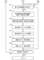
- FIG. 3 is a flowchart showing an optical reaction evaluation operation of the data processing unit of FIG.
- FIG. 4 is a flowchart showing an optical reaction evaluation operation of the data processing unit of FIG.
- FIG. 5 is a diagram for explaining a standard data acquisition operation.
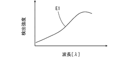
- FIG. 6 is a diagram showing an example of the first detection intensity distribution acquired by the standard data acquisition operation.
- FIG. 7 is a diagram for explaining the first measurement operation.
- FIG. 8 is a diagram showing an example of the second detected intensity distribution acquired by the first measurement operation.
- FIG. 9 is a diagram for explaining a method of calculating the radiation intensity at each wavelength of the irradiation light source.
- FIG. 1 is a block diagram showing a configuration of a photochemical evaluation device according to an embodiment.
- the photochemical reaction evaluation device 100 of FIG. 1 includes a measurement unit 10 and a data processing unit 30.
- the measuring unit 10 includes an irradiation light source 1, a spectrophotometer 2, and a sample cell 3.
- Sample S is set in the sample cell 3.
- the position of the sample cell 3 corresponds to the sample position.
- the evaluation of the photoreaction of the sample S includes the evaluation of the number of absorbed photons in the photochemical reaction of the sample S.
- the irradiation light source 1 irradiates the sample cell 3 with light as excitation light.
- a light source that generates light having a specific wavelength, light in a specific wavelength range, multi-wavelength light, or white light can be used.
- the irradiation light source 1 may be various light sources such as an LED (light emitting diode), a xenon lamp, a mercury lamp, or a deuterium lamp.
- the spectrophotometer 2 includes a measurement light source 21, a spectroscope (not shown), and a detection unit 22. In this embodiment, for example, a multi-channel spectrophotometer 2 using a polychromator can be used.
- the data processing unit 30 includes a CPU (central processing unit) 31, a RAM (random access memory) 32, a ROM (read-only memory) 33, an input / output I / F (interface) 34, and a storage device 35.
- the CPU 31, RAM 32, ROM 33, input / output I / F 34, and storage device 35 are connected to the bus 36.
- the operation unit 40 and the display unit 50 are connected to the bus 36 of the data processing unit 30.
- the operation unit 40 includes a keyboard, a mouse, and the like, and is operated by a user to input various commands and data to the data processing unit 30.
- the display unit 50 includes a liquid crystal display, an organic EL (electroluminescence) display, and the like, and displays various data and the like.
- the storage device 35 includes a storage medium such as a semiconductor memory or a memory card, and stores the photochemical evaluation program.
- the RAM 32 is used as a work area of the CPU 31.
- the system program is stored in the ROM 33.
- the CPU 31 controls the irradiation light source 1 and the spectrophotometer 2 through the input / output I / F 34 by executing the optical reaction evaluation program stored in the storage device 35 on the RAM 32, and inputs the output signal of the spectrophotometer 2. Received through output I / F34. As a result, the photoreaction evaluation method described later is carried out.
- the photochemical reaction evaluation method includes a method for calculating the number of photons.
- the photochemical evaluation apparatus 100 executes a standard data acquisition operation using the standard light source 1S (FIG. 2) described later, a first measurement operation using the irradiation light source 1, and a second measurement operation for measuring the sample S. do.
- FIG. 2 is a block diagram showing a functional configuration of the data processing unit 30 of FIG.
- the data processing unit 30 includes an intensity distribution acquisition unit 310, a storage unit 320, a radiation intensity calculation unit 330, an irradiation photon number calculation unit 340, an operation control unit 350, an absorbance spectrum acquisition unit 360, and an absorption photon number. It includes a calculation unit 370 and a display control unit 380.
- the functions of the above components (310 to 380) are realized by the CPU 31 of FIG. 1 executing a photoreaction evaluation program which is a computer program stored in a storage medium (recording medium) such as a storage device 35.
- a part or all the components of the data processing unit 30 may be realized by hardware such as an electronic circuit.
- the standard light source 1S shown by the alternate long and short dash line in FIG. 2 is attached to the measurement unit 10 (FIG. 1) instead of the irradiation light source 1.
- the standard light source 1S is a light source that generates light having a wavelength range equal to or larger than the wavelength range of the light generated by the irradiation light source 1.
- a white light source is used as the standard light source 1S.
- the white light source is, for example, an LED that generates white light, but other white light sources may be used.
- the standard light source 1S is a light source that generates light in a wide wavelength range.
- the radiation intensity distribution of the light generated by the standard light source 1S at all wavelengths is referred to as the radiation characteristic of the standard light source 1S.
- the radiation characteristics include the radiation intensity at each wavelength of the light generated by the standard light source 1S.
- the radiation characteristics of the standard light source 1S have been accurately measured in advance. Since the spectrophotometer 2 has a wavelength sensitivity distribution characteristic that depends on the wavelength, the radiation intensity distribution of the light generated by the standard light source 1S and the intensity distribution of the light from the standard light source 1S detected by the spectrophotometer 2 are usually used. Is different.
- the intensity distribution acquisition unit 310 acquires the light intensity distribution detected by the detection unit 22 of the spectrophotometer 2 as the first detection intensity distribution during the standard data acquisition operation.
- the first detected intensity distribution is the intensity distribution of the light detected at all wavelengths of the white light irradiated to the sample cell 3 by the standard light source 1S.
- the intensity distribution acquisition unit 310 acquires the light intensity distribution detected by the detection unit 22 of the spectrophotometer 2 as the second detection intensity distribution during the first measurement operation.
- the second detected intensity distribution is the intensity distribution of the light detected in the wavelength range of the light irradiated to the sample cell 3 by the irradiation light source 1.
- the second detected intensity distribution is the intensity distribution of the light detected at all wavelengths.
- the irradiation light source 1 is a light source that generates light having a specific wavelength or light in a specific wavelength range
- the second detection intensity distribution is the intensity distribution of the light detected in the specific wavelength or the specific wavelength range. be.
- the storage unit 320 stores the first detected intensity distribution acquired by the intensity distribution acquisition unit 310 at the time of standard data acquisition and the second detected intensity distribution acquired by the intensity distribution acquisition unit 310 during the first measurement operation. Further, the storage unit 320 stores in advance the radiation characteristics of the standard light source 1S. Further, the storage unit 320 stores the number of irradiated photons calculated by the irradiation photon number calculation unit 340, which will be described later, and the number of absorbed photons calculated by the absorption photon number calculation unit 370.
- the radiation intensity calculation unit 330 is based on the first detection intensity distribution, the second detection intensity distribution, and the radiation intensity at each wavelength of the standard light source 1S stored in the storage unit 320 during the first measurement operation. The radiation intensity at each wavelength of the irradiation light source 1 is calculated. The details of the calculation method will be described later.
- the irradiation photon number calculation unit 340 is based on the radiation intensity at each wavelength calculated by the radiation intensity calculation unit 330, and the irradiation photon number calculation unit 340 is the number of photons of the light irradiated to the sample cell 3 by the irradiation light source 1 (hereinafter, referred to as the irradiation photon number). ) Is calculated. The details of the calculation method will be described later.
- the operation control unit 350 controls the operation of each component of the data processing unit 30 in order to execute the standard data acquisition operation, the first measurement operation, and the second measurement operation based on the operation of the operation unit 40 by the user. At the same time, the operation of the standard light source 1S, the irradiation light source 1, and the measurement light source 21 of the spectrophotometer 2 is controlled.
- the absorbance spectrum acquisition unit 360 acquires the light intensity distribution detected by the detection unit 22 of the spectrophotometer 2 as an absorbance spectrum during the second measurement operation.
- the absorption photon number calculation unit 370 calculates the number of absorbed photons at each wavelength based on the absorbance spectrum acquired by the absorbance spectrum acquisition unit 360 and the irradiation photon number calculated by the irradiation photon number calculation unit 340. The details of the calculation method will be described later.
- the display control unit 380 is acquired by the irradiation photon number calculation unit 340 calculated by the irradiation photon number calculation unit 340, the absorption photon number calculated by the absorption photon number calculation unit 370, and the absorbance spectrum acquisition unit 360 based on the operation of the operation unit 40.
- the obtained absorbance spectrum is displayed on the display unit 50.
- FIGS. 3 and 4 are flowcharts showing a photochemical evaluation operation of the data processing unit 30 of FIG.
- FIG. 5 is a diagram for explaining a standard data acquisition operation.
- FIG. 6 is a diagram showing an example of the first detection intensity distribution acquired by the standard data acquisition operation.
- FIG. 7 is a diagram for explaining the first measurement operation.
- FIG. 8 is a diagram showing an example of the second detected intensity distribution acquired by the first measurement operation.
- FIG. 9 is a diagram for explaining a method of calculating the radiation intensity at each wavelength of the irradiation light source 1.
- the vertical axis of FIGS. 6, 8 and 9 represents the detection intensity at each wavelength detected by the spectrophotometer 2, and the horizontal axis represents the wavelength ⁇ .
- the photochemical evaluation operation of the photochemical evaluation device 100 includes a standard data acquisition operation, a first measurement operation, and a second measurement operation as described above.
- the photochemical reaction evaluation operation of FIGS. 3 and 4 is performed by the CPU 31 of FIG. 2 executing the photochemical evaluation program.
- the standard data acquisition operation is performed, for example, at the time of installation or maintenance of the photochemical reaction evaluation device 100.
- the standard data includes the first detection intensity distribution and the radiation characteristics of the standard light source 1S (radiant intensity at each wavelength).
- the first measurement operation is performed on a daily basis, for example.
- the second measurement operation is performed when the sample S is measured.
- the operator attaches the standard light source 1S to the operation unit 40 instead of the irradiation light source 1.
- Sample S is not set in the sample cell 3.
- the operation control unit 350 determines whether or not the standard data acquisition operation is instructed by the operation unit 40 (step S1).
- the operation control unit 350 controls the standard light source 1S so that the standard light source 1S irradiates the sample cell 3 with light (step S2).
- the light emitted from the standard light source 1S is applied to the sample cell 3, and the light from the sample cell 3 is incident on the spectrophotometer 2.
- the sample cell 3 is not irradiated with light from the measurement light source 21 of the spectrophotometer 2.
- the intensity distribution acquisition unit 310 acquires the light intensity distribution detected by the detection unit 22 of the spectrophotometer 2 as the first detection intensity distribution (step S3).
- the relationship between the detection intensity and the wavelength ⁇ is shown as the first detection intensity distribution E1.
- the intensity distribution acquisition unit 310 stores the acquired first detected intensity distribution E1 in the storage unit 320 (step S4). This completes the standard data acquisition operation.
- the user attaches the irradiation light source 1 to the measurement unit 10.
- Sample S is not set in the sample cell 3.
- the operation control unit 350 determines whether or not the first measurement operation is instructed by the operation unit 40 (step S5).
- the operation control unit 350 controls the irradiation light source 1 so that the irradiation light source 1 irradiates the sample cell 3 with light (step S6).
- the light emitted by the irradiation light source 1 is applied to the sample cell 3, and the light from the sample cell 3 is incident on the spectrophotometer 2.
- the sample cell 3 is not irradiated with light from the measurement light source 21 of the spectrophotometer 2.
- the intensity distribution acquisition unit 310 acquires the light intensity distribution detected by the detection unit 22 of the spectrophotometer 2 as the second detection intensity distribution (step S7).
- the relationship between the detection intensity and the wavelength ⁇ is shown as the second detection intensity distribution E2.
- the intensity distribution acquisition unit 310 stores the acquired second detected intensity distribution E2 in the storage unit 320 (step S8).
- the radiation intensity calculation unit 330 emits radiation at each wavelength of the irradiation light source 1 by the following method from the radiation characteristics of the first detection intensity distribution E1, the second detection intensity distribution E2, and the standard light source 1S stored in the storage unit 320.
- the intensity is calculated (step S9).
- each wavelength means a fixed wavelength section divided at a specific pitch.
- the first detection intensity distribution E1 is expressed by the following equation.
- the second detection intensity distribution E2 is expressed by the following equation.
- the radiation characteristic Filter of the irradiation light source 1 represents the radiation intensity distribution of the light generated by the irradiation light source 1.
- the radiation characteristic Filter includes the radiation intensity at each wavelength of the irradiation light source 1.
- the radiation characteristics Fstd of the first detected intensity distribution E1 and the standard light source 1S are known. Therefore, the radiation characteristics of the irradiation light source 1 can be obtained from the above equation (4) by obtaining the second detection intensity distribution E2 of the irradiation light source 1 using the spectrophotometer 2 capable of detecting the light intensity at each wavelength.
- the Filter can be calculated. As a result, not only a light source that generates light of a specific wavelength, but also a light source that generates light in a specific wavelength range, a light source that generates multi-wavelength light, and a light source that generates white light are obtained with radiation intensity at each wavelength. be able to.
- the radiation intensity calculation unit 330 can calculate the radiation intensity at each wavelength of the irradiation light source 1 by the following method.
- the first detection intensity distribution E1 and the second detection intensity distribution E2 are divided into a plurality of wavelength sections at a constant wavelength pitch.
- the radiation intensity calculation unit 330 calculates the area under the first and second detection intensity distributions E1 and E2 in each wavelength section.
- the area under the first detection intensity distribution E1 in the arbitrary wavelength section of the first detection intensity distribution E1 is E1i
- the second detection intensity distribution in the arbitrary wavelength section of the second detection intensity distribution E2 is defined as E1i.
- E2i be the area under E2. i is a natural number.
- the areas of the plurality of wavelength sections of the first detection intensity distribution E1 are E11, E12, ... E1i, ...
- the areas of the plurality of wavelength sections of the second detection intensity distribution E2 are E21, E22, ... E2i, ...
- the radiation intensity of the standard light source 1S in an arbitrary wavelength section is defined as Fstdi.
- the radiation intensity calculation unit 330 calculates the radiation intensity Firri of the irradiation light source 1 in an arbitrary wavelength section from the following equation (step S9).
- the number of irradiated photons Nirr ( ⁇ ) at the wavelength ⁇ is defined by the following equation from Einstein's energy equation using Planck's constant h, speed of light c and radiant intensity Firri.
- the wavelength ⁇ corresponds to the i-th wavelength interval.
- Nirr ( ⁇ ) ( ⁇ / hc) ⁇ Firri... (6)
- the irradiation photon number calculation unit 340 calculates the irradiation photon number Nirr ( ⁇ ) at each wavelength ⁇ from the above equation (6) by using the radiation intensity Firri in each wavelength section calculated from the above equation (5). (Step S10).
- the irradiation photon number calculation unit 340 stores the calculated irradiation photon number Nirr ( ⁇ ) at each wavelength ⁇ in the storage unit 320 (step S11). As a result, the first measurement operation is completed.
- the user sets the sample S in the sample cell 3 of the measurement unit 10 (FIG. 1).
- the operation control unit 350 determines whether or not the second measurement operation is instructed by the operation unit 40 (step S12).
- the operation control unit 350 controls the measurement light source 21 so that the measurement light source 21 of the spectrophotometer 2 irradiates the sample in the sample cell 3 with light as the measurement light (Ste S13).
- the operation control unit 350 controls the irradiation light source 1 so that the irradiation light source 1 irradiates the sample in the sample cell 3 with light as excitation light (step S14).
- the photons of the excitation light irradiated by the irradiation light source 1 are absorbed by the sample S, and a photochemical reaction occurs.
- the number of photons absorbed depends on the wavelength ⁇ .
- the detection unit 22 of the spectrophotometer 2 detects the intensity distribution of light from the sample S.
- the absorbance spectrum acquisition unit 360 acquires the light intensity distribution detected by the detection unit 22 of the spectrophotometer 2 as an absorbance spectrum (step S15). Further, the absorbance spectrum acquisition unit 360 stores the acquired absorbance spectrum in the storage unit 320 (step S16). During the measurement period, the sample S is irradiated with the excitation light having the number of irradiated photons Nirr ( ⁇ ) by the irradiation light source 1. The photochemical reaction proceeds according to the number of irradiated photons Nirr ( ⁇ ). Therefore, the absorbance spectrum acquisition unit 360 acquires the absorbance spectrum, which is time series data. Here, the absorbance spectrum at the time point t is defined as Abs (t, ⁇ ).
- the number of photons absorbed by the sample S at the wavelength ⁇ at the time point t is defined as the number of absorbed photons Nabs (t, ⁇ ).
- the number of absorbed photons Nabs (t, ⁇ ) is expressed by the following equation.
- Nabs (t, ⁇ ) ⁇ ⁇ (1-10 ⁇ Abs (t, ⁇ ) ) ⁇ Nirr ( ⁇ ) ... (7)
- ⁇ is a coefficient for correcting the irradiation light reflection component by the sample cell 3.
- the absorption photon number calculation unit 370 uses the above equation (7) using the irradiation photon number Nirr ( ⁇ ) calculated by the irradiation photon number calculation unit 340 and the absorbance spectrum Abs (t, ⁇ ) acquired by the absorbance spectrum acquisition unit 360. ) To calculate the number of absorbed photons Nabs (t, ⁇ ) (step S17). Further, the absorption photon number calculation unit 370 stores the calculated absorption photon number Nabs (t, ⁇ ) in the storage unit 320 (step S18). As a result, the second measurement operation is completed.
- the operation control unit 350 determines whether or not the operation end is instructed by the operation unit 40 (step S19). If the end of operation is not instructed, the operation control unit 350 returns to step S1. If the standard data acquisition operation is not instructed in step S1, the operation control unit 350 proceeds to step S5. If the first measurement operation is not instructed in step S5, the operation control unit 350 proceeds to step S12. If the second measurement operation is not instructed in step S12, the operation control unit 350 proceeds to step S19. When the operation end is instructed in step S19, the operation control unit 350 ends the photoreaction evaluation operation.
- the quantum yield in the photochemical reaction can be calculated using the number of molecules (atoms or molecules) of the substance (atom or molecule) produced by the photochemical reaction in the sample S and the number of absorbed photons calculated by the second measurement operation described above.
- the number of molecules of the substance produced by the photochemical reaction in Sample S can be obtained, for example, by analyzing Sample S using a gas chromatograph or a liquid chromatograph.
- the first detection intensity distribution E1 obtained by using the standard light source 1S that generates white light has each wavelength in a wide wavelength range.
- the radiation characteristic Fstd of the standard light source 1S includes the radiation intensity at each wavelength in a wide wavelength range. Therefore, during the first measurement operation, the radiation intensity at each wavelength in the wavelength range of the irradiation light of the irradiation light source 1 can be accurately calculated. Thereby, the number of irradiated photons at each wavelength in the wavelength range of the irradiation light of the irradiation light source 1 can be accurately calculated.
- the distribution of the number of irradiation photons depending on the wavelength is accurate not only when the irradiation light source 1 that generates light having a specific wavelength is used but also when the irradiation light source 1 that generates light having a wide wavelength range is used. It is possible to calculate.
- the wavelength of the irradiation light of the irradiation light source 1 is calculated during the second measurement operation.
- the number of absorbed photons at each wavelength in the range can be calculated accurately.
- the first detection intensity distribution E1 acquired at the time of standard data acquisition is stored in the storage unit 320. As a result, it is not necessary to detect the first detection intensity distribution E1 using the standard light source 1S during the first measurement operation. Therefore, the time and labor required for the first measurement operation can be reduced.
- a white light source is used as the standard light source 1S
- a light source that generates light of various wavelengths or wavelength ranges can be used as the irradiation light source 1.
- the number of irradiated photons at each wavelength of various irradiation light sources 1 can be accurately calculated. Therefore, the number of absorbed photons by the sample S can be accurately calculated by using the light having a desired wavelength.
- the position of the sample cell 3 corresponds to the sample position, but the sample position is not limited to the position of the sample cell 3, and another sample in which the sample S is held or supported is not limited. It may be the position of the holding part or the sample supporting part.
- the data processing unit 30 of the optical reaction evaluation device 100 may be configured by a personal computer, a portable electronic terminal such as a smartphone, or a server connected to a network.
- the photochemical evaluation device is a photoreaction evaluation device that evaluates the photochemical reaction of a sample placed at a sample position.
- An irradiation light source that is arranged so that light can be irradiated as irradiation light at the sample position and is interchangeably provided with a standard light source that generates white light.
- a spectrophotometer including a measurement light source arranged so as to irradiate the sample position with light, and a detection unit arranged to detect the intensity distribution of light from the sample position.
- the light intensity distribution detected by the detection unit in a state where the sample position where the sample does not exist is irradiated with light by the standard light source and the sample position is not irradiated with light by the measurement light source is defined as the first detection intensity distribution. It is detected by the detection unit in a state where the sample position where the sample does not exist is irradiated with light as irradiation light by the irradiation light source and the sample position is not irradiated with light by the measurement light source during the first measurement operation.
- An intensity distribution acquisition unit that acquires the intensity distribution of the light source as the second detected intensity distribution, Each of the irradiation light of the irradiation light source is based on the first detection intensity distribution acquired by the intensity distribution acquisition unit, the second detection intensity distribution acquired by the intensity distribution acquisition unit, and the radiation characteristics of the standard light source.
- a radiant intensity calculation unit that calculates the radiant intensity at a wavelength
- An irradiation photon number calculation unit that calculates the number of photons at each wavelength of the irradiation light of the irradiation light source as the irradiation photon number based on the radiation intensity at each wavelength calculated by the radiation intensity calculation unit may be provided.
- the first detection intensity distribution obtained by using a standard light source is acquired.
- the radiation characteristics of standard illuminants are known.
- the intensity distribution of the light detected by the detection unit in the state where the sample position is irradiated with the light by the irradiation light source is acquired as the second detection intensity distribution.
- the radiation intensity at each wavelength of the irradiation light of the irradiation light source is calculated based on the acquired first detection intensity distribution, the acquired second detection intensity distribution, and the radiation characteristics of the standard light source.
- the number of irradiated photons of the irradiation light source is calculated based on the calculated radiation intensity at each wavelength.
- the first detection intensity distribution obtained by using the standard light source that generates white light includes the detection intensity at each wavelength in a wide wavelength range
- the radiation characteristic of the standard light source includes the detection intensity at each wavelength in a wide wavelength range. Including radiation intensity. Therefore, during the first measurement operation, the radiation intensity at each wavelength in the wavelength range of the irradiation light of the irradiation light source can be accurately calculated. Thereby, the number of irradiated photons at each wavelength in the wavelength range of the irradiation light of the irradiation light source can be accurately calculated.
- the distribution of the number of irradiation photons depending on the wavelength is accurately calculated not only when an irradiation light source that generates light having a specific wavelength is used but also when an irradiation light source that generates light having a wide wavelength range is used. It is possible to do.
- the photochemical evaluation device is In the second measurement operation, the intensity distribution of the light detected by the detection unit in a state where the sample at the sample position is irradiated with light by the measurement light source and the sample at the sample position is irradiated with light by the irradiation light source.
- As an absorbance spectrum acquisition unit During the second measurement operation, the number of photons absorbed at each wavelength by the sample is absorbed based on the number of irradiated photons calculated by the irradiation photon number calculation unit and the absorbance spectrum acquired by the absorbance spectrum acquisition unit.
- a unit for calculating the number of absorbed photons, which is calculated as the number of photons, may be further provided.
- the absorbance spectrum is the intensity distribution of light detected by the spectrophotometer in a state where the sample at the sample position is irradiated with light by the irradiation light source during the second measurement operation. Is obtained as.
- the number of absorbed photons is calculated based on the number of irradiated photons and the absorbance spectrum. In this case, during the first measurement operation, the number of irradiated photons at each wavelength in the wavelength range of the irradiation light of the irradiation light source is accurately calculated. Therefore, the number of absorbed photons at each wavelength in the wavelength range of the irradiation light of the irradiation light source can be accurately calculated.
- a storage unit that stores the first detected intensity distribution acquired by the intensity distribution acquisition unit may be further provided during the first measurement operation and before the second measurement operation.
- the intensity distribution acquisition unit may acquire the first detection intensity distribution stored in the storage unit during the first measurement operation.
- the first detection intensity distribution acquired before the first measurement operation and the second measurement operation is stored in the storage unit. As a result, it is not necessary to detect the first detection intensity distribution using a standard light source during the first measurement operation. Therefore, the time and labor required for the first measurement operation can be reduced.
- a light source that generates white light, monochromatic light, or light in a certain wavelength range may be selectively provided.
- a light source that generates light of various wavelengths or wavelength ranges can be used as an irradiation light source. Thereby, it is possible to accurately evaluate the photoreaction of various samples using light of a desired wavelength.
- the photon number calculation method is a photon number calculation method in a photoreaction evaluation device that evaluates a photoreaction of a sample placed at a sample position. Light detected by the detector of the spectrophotometer in a state where the sample position is irradiated with light by a standard light source that generates white light and the sample position is not irradiated with light by the measurement light source of the spectrophotometer.
- the step of acquiring the distribution as the second detected intensity distribution A step of calculating the radiation intensity at each wavelength of the irradiation light of the irradiation light source based on the acquired first detection intensity distribution, the acquired second detection intensity distribution, and the radiation characteristics of the standard light source. , A step of calculating the number of photons at each wavelength of the irradiation light of the irradiation light source as the number of irradiation photons based on the calculated radiation intensity at each wavelength may be included.
- the first detection intensity distribution corresponding to the standard light source that generates white light includes the detection intensity at each wavelength in a wide wavelength range, and the radiation characteristic of the standard light source is Includes radiant intensity at each wavelength over a wide wavelength range. Therefore, during the first measurement operation, the radiation intensity at each wavelength in the wavelength range of the irradiation light of the irradiation light source can be accurately calculated. Thereby, the number of irradiated photons at each wavelength in the wavelength range of the irradiation light of the irradiation light source can be accurately calculated.
- the distribution of the number of irradiation photons depending on the wavelength is accurately calculated not only when an irradiation light source that generates light having a specific wavelength is used but also when an irradiation light source that generates light having a wide wavelength range is used. It is possible to do.
- the number of irradiated photons at each wavelength is accurately calculated during the first measurement operation. Therefore, during the second measurement operation, the number of absorbed photons at each wavelength of the irradiation light of the irradiation light source can be accurately calculated.
Landscapes
- Physics & Mathematics (AREA)
- Spectroscopy & Molecular Physics (AREA)
- Health & Medical Sciences (AREA)
- General Physics & Mathematics (AREA)
- Chemical & Material Sciences (AREA)
- Analytical Chemistry (AREA)
- Biochemistry (AREA)
- General Health & Medical Sciences (AREA)
- Life Sciences & Earth Sciences (AREA)
- Immunology (AREA)
- Pathology (AREA)
- Nuclear Medicine, Radiotherapy & Molecular Imaging (AREA)
- Engineering & Computer Science (AREA)
- Mathematical Physics (AREA)
- Theoretical Computer Science (AREA)
- Investigating Or Analysing Materials By Optical Means (AREA)
- Investigating, Analyzing Materials By Fluorescence Or Luminescence (AREA)
- Spectrometry And Color Measurement (AREA)
- Testing Or Measuring Of Semiconductors Or The Like (AREA)
Abstract
Description
図1は一実施の形態に係る光反応評価装置の構成を示すブロック図である。図1の光反応評価装置100は、測定部10およびデータ処理部30を備える。測定部10は、照射光源1、分光光度計2および試料セル3を含む。試料セル3には、試料Sがセットされる。本実施の形態では、試料セル3の位置が試料位置に相当する。また、本実施の形態において、試料Sについての光反応の評価は、試料Sの光化学反応における吸収フォトン数の評価を含む。
図2は図1のデータ処理部30の機能的な構成を示すブロック図である。図2に示すように、データ処理部30は、強度分布取得部310、記憶部320、放射強度算出部330、照射フォトン数算出部340、動作制御部350、吸光度スペクトル取得部360、吸収フォトン数算出部370および表示制御部380を含む。上記の構成要素(310~380)の機能は、図1のCPU31が記憶装置35等の記憶媒体(記録媒体)に記憶されたコンピュータプログラムである光反応評価プログラムを実行することにより実現される。なお、データ処理部30の一部または全ての構成要素が電子回路等のハードウエアにより実現されてもよい。
図3および図4は図2のデータ処理部30の光反応評価動作を示すフローチャートである。図5は標準データ取得動作を説明するための図である。図6は標準データ取得動作により取得された第1の検出強度分布の例を示す図である。図7は第1の測定動作を説明するための図である。図8は第1の測定動作により取得された第2の検出強度分布の例を示す図である。図9は照射光源1の各波長での放射強度の算出方法を説明するための図である。図6、図8および図9の縦軸は、分光光度計2により検出される各波長での検出強度を表し、横軸は波長λを表す。
照射光源1の放射特性をFirrとすると、第2の検出強度分布E2は次式で表される。ここで、照射光源1の放射特性Firrは、照射光源1により発生される光の放射強度分布を表す。放射特性Firrは、照射光源1の各波長での放射強度を含む。
上式(1)および(2)より次式が得られる。
上式(3)より次式が得られる。
第1の検出強度分布E1および標準光源1Sの放射特性Fstdは既知である。したがって、各波長での光の強度を検出することができる分光光度計2を用いて、照射光源1の第2の検出強度分布E2を得ることにより上式(4)から照射光源1の放射特性Firrを算出することができる。それにより、特定波長の光を発生する光源だけでなく、特定の波長範囲の光を発生する光源、多波長の光を発生する光源および白色光を発生する光源について各波長での放射強度を得ることができる。
波長λにおける照射フォトン数Nirr(λ)は、プランク定数h、光の速度cおよび放射強度Firriを用いてアインシュタインのエネルギーの式より次式で定義される。本実施の形態では、波長λは、i番目の波長区間に相当する。
照射フォトン数算出部340は、上式(5)より算出される各波長区間での放射強度Firriを用いて、上式(6)より各波長λでの照射フォトン数Nirr(λ)を算出する(ステップS10)。照射フォトン数算出部340は、算出された各波長λでの照射フォトン数Nirr(λ)を記憶部320に記憶させる(ステップS11)。これにより、第1の測定動作が完了する。
…(7)
上式(7)において、αは試料セル3による照射光反射成分を補正するための係数である。吸収フォトン数算出部370は、照射フォトン数算出部340により算出された照射フォトン数Nirr(λ)および吸光度スペクトル取得部360により取得された吸光度スペクトルAbs(t,λ)を用いて上式(7)より吸収フォトン数Nabs(t,λ)を算出する(ステップS17)。また、吸収フォトン数算出部370は、算出された吸収フォトン数Nabs(t,λ)を記憶部320に記憶させる(ステップS18)。これにより、第2の測定動作が完了する。
本実施の形態に係る光反応評価装置100においては、白色光を発生する標準光源1Sを用いて得られた第1の検出強度分布E1は広い波長範囲における各波長での検出強度を含み、標準光源1Sの放射特性Fstdは広い波長範囲における各波長での放射強度を含む。そのため、第1の測定動作時に、照射光源1の照射光の波長範囲における各波長での放射強度を正確に算出することができる。それにより、照射光源1の照射光の波長範囲における各波長での照射フォトン数を正確に算出することができる。
上記実施の形態では、試料セル3の位置が試料位置に相当するが、試料位置は試料セル3の位置に限らず、試料Sが保持または支持される他の試料保持部または試料支持部の位置であってもよい。
上述した複数の例示的な実施の形態は、以下の態様の具体例であることが当業者により理解される。
前記試料位置に光を照射光として照射可能に配置されるとともに、白色光を発生する標準光源に交換可能に設けられた照射光源と、
前記試料位置に光を照射可能に配置された測定光源、および前記試料位置からの光の強度分布を検出するように配置された検出部を含む分光光度計と、
試料が存在しない前記試料位置に前記標準光源により光が照射されかつ前記試料位置に前記測定光源により光が照射されない状態で前記検出部により検出された光の強度分布を第1の検出強度分布として取得し、第1の測定動作時に、試料が存在しない前記試料位置に前記照射光源により光が照射光として照射されかつ前記試料位置に前記測定光源により光が照射されない状態で前記検出部により検出された光の強度分布を第2の検出強度分布として取得する強度分布取得部と、
前記強度分布取得部により取得された第1の検出強度分布、前記強度分布取得部により取得された第2の検出強度分布および前記標準光源の放射特性に基づいて、前記照射光源の照射光の各波長での放射強度を算出する放射強度算出部と、
前記放射強度算出部により算出された各波長での放射強度に基づいて前記照射光源の照射光の各波長でのフォトン数を照射フォトン数として算出する照射フォトン数算出部とを備えてもよい。
第2の測定動作時に、前記試料位置の試料に前記測定光源により光が照射されかつ前記試料位置の試料に前記照射光源により光が照射された状態で前記検出部により検出された光の強度分布を吸光度スペクトルとして取得する吸光度スペクトル取得部と、
前記第2の測定動作時に、前記照射フォトン数算出部により算出された照射フォトン数および前記吸光度スペクトル取得部により取得された吸光度スペクトルに基づいて、試料により各波長で吸収されたフォトンの数を吸収フォトン数として算出する吸収フォトン数算出部とをさらに備えてもよい。
前記第1の測定動作時および前記第2の測定動作時より前に、前記強度分布取得部により取得された第1の検出強度分布を記憶する記憶部をさらに備えてもよく、
前記強度分布取得部は、前記第1の測定動作時に、前記記憶部に記憶された第1の検出強度分布を取得してもよい。
前記照射光源として、白色光、単色光または一定波長範囲の光を発生する光源が選択的に設けられてもよい。
試料が存在しない前記試料位置に白色光を発生する標準光源により光が照射されかつ前記試料位置に分光光度計の測定光源により光が照射されない状態で前記分光光度計の検出部により検出された光の強度分布を第1の検出強度分布として取得するステップと、
第1の測定動作時に、試料が存在しない前記試料位置に照射光源により光が照射光として照射されかつ前記試料位置に前記測定光源により光が照射されない状態で前記検出部により検出された光の強度分布を第2の検出強度分布として取得するステップと、
前記取得された第1の検出強度分布、前記取得された第2の検出強度分布および前記標準光源の放射特性に基づいて、前記照射光源の照射光の各波長での放射強度を算出するステップと、
前記算出された各波長での放射強度に基づいて前記照射光源の照射光の各波長でのフォトン数を照射フォトン数として算出するステップとを含んでもよい。
第2の測定動作時に、前記試料位置の試料に前記測定光源により光が照射されかつ前記試料位置の試料に前記照射光源により光が照射された状態で前記検出部により生成された光の強度分布を吸光度スペクトルとして取得するステップと、
前記第2の測定動作時に、前記算出された照射フォトン数および前記取得された吸光度スペクトルに基づいて、試料により各波長で吸収されたフォトンの数を吸収フォトン数として算出するステップとをさらに含んでもよい。
Claims (6)
- 試料位置に配置された試料の光反応を評価する光反応評価装置であって、
前記試料位置に光を照射光として照射可能に配置されるとともに、白色光を発生する標準光源に交換可能に設けられた照射光源と、
前記試料位置に光を照射可能に配置された測定光源、および前記試料位置からの光の強度分布を検出するように配置された検出部を含む分光光度計と、
試料が存在しない前記試料位置に前記標準光源により光が照射されかつ前記試料位置に前記測定光源により光が照射されない状態で前記検出部により検出された光の強度分布を第1の検出強度分布として取得し、第1の測定動作時に、試料が存在しない前記試料位置に前記照射光源により光が照射光として照射されかつ前記試料位置に前記測定光源により光が照射されない状態で前記検出部により検出された光の強度分布を第2の検出強度分布として取得する強度分布取得部と、
前記強度分布取得部により取得された第1の検出強度分布、前記強度分布取得部により取得された第2の検出強度分布および前記標準光源の放射特性に基づいて、前記照射光源の照射光の各波長での放射強度を算出する放射強度算出部と、
前記放射強度算出部により算出された各波長での放射強度に基づいて前記照射光源の照射光の各波長でのフォトン数を照射フォトン数として算出する照射フォトン数算出部とを備えた、光反応評価装置。 - 第2の測定動作時に、前記試料位置の試料に前記測定光源により光が照射されかつ前記試料位置の試料に前記照射光源により光が照射された状態で前記検出部により検出された光の強度分布を吸光度スペクトルとして取得する吸光度スペクトル取得部と、
前記第2の測定動作時に、前記照射フォトン数算出部により算出された照射フォトン数および前記吸光度スペクトル取得部により取得された吸光度スペクトルに基づいて、試料により各波長で吸収されたフォトンの数を吸収フォトン数として算出する吸収フォトン数算出部とをさらに備えた、請求項1記載の光反応評価装置。 - 前記第1の測定動作時および前記第2の測定動作時より前に、前記強度分布取得部により取得された第1の検出強度分布を記憶する記憶部をさらに備え、
前記強度分布取得部は、前記第1の測定動作時に、前記記憶部に記憶された第1の検出強度分布を取得する、請求項1または2記載の光反応評価装置。 - 前記照射光源として、白色光、単色光または一定波長範囲の光を発生する光源が選択的に設けられる、請求項1~3のいずれか一項に記載の光反応評価装置。
- 試料位置に配置された試料についての光反応を評価する光反応評価装置におけるフォトン数算出方法であって、
試料が存在しない前記試料位置に白色光を発生する標準光源により光が照射されかつ前記試料位置に分光光度計の測定光源により光が照射されない状態で前記分光光度計の検出部により検出された光の強度分布を第1の検出強度分布として取得するステップと、
第1の測定動作時に、試料が存在しない前記試料位置に照射光源により光が照射光として照射されかつ前記試料位置に前記測定光源により光が照射されない状態で前記検出部により検出された光の強度分布を第2の検出強度分布として取得するステップと、
前記取得された第1の検出強度分布、前記取得された第2の検出強度分布および前記標準光源の放射特性に基づいて、前記照射光源の照射光の各波長での放射強度を算出するステップと、
前記算出された各波長での放射強度に基づいて前記照射光源の照射光の各波長でのフォトン数を照射フォトン数として算出するステップとを含む、フォトン数算出方法。 - 第2の測定動作時に、前記試料位置の試料に前記測定光源により光が照射されかつ前記試料位置の試料に前記照射光源により光が照射された状態で前記検出部により生成された光の強度分布を吸光度スペクトルとして取得するステップと、
前記第2の測定動作時に、前記算出された照射フォトン数および前記取得された吸光度スペクトルに基づいて、試料により各波長で吸収されたフォトンの数を吸収フォトン数として算出するステップとをさらに含む、請求項5記載のフォトン数算出方法。
Priority Applications (5)
| Application Number | Priority Date | Filing Date | Title |
|---|---|---|---|
| EP20919516.3A EP4109075A4 (en) | 2020-02-20 | 2020-09-28 | Photoreaction evaluation device and photon count calculation method |
| CN202080096404.9A CN115104023A (zh) | 2020-02-20 | 2020-09-28 | 光反应评价装置和光子数计算方法 |
| US17/792,572 US20230082052A1 (en) | 2020-02-20 | 2020-09-28 | Photoreaction evaluation device and photon count calculation method |
| JP2022501618A JP7315088B2 (ja) | 2020-02-20 | 2020-09-28 | 光反応評価装置およびフォトン数算出方法 |
| KR1020227027926A KR102775938B1 (ko) | 2020-02-20 | 2020-09-28 | 광 반응 평가 장치 및 포톤수 산출 방법 |
Applications Claiming Priority (2)
| Application Number | Priority Date | Filing Date | Title |
|---|---|---|---|
| JP2020027514 | 2020-02-20 | ||
| JP2020-027514 | 2020-02-20 |
Publications (1)
| Publication Number | Publication Date |
|---|---|
| WO2021166310A1 true WO2021166310A1 (ja) | 2021-08-26 |
Family
ID=77390601
Family Applications (1)
| Application Number | Title | Priority Date | Filing Date |
|---|---|---|---|
| PCT/JP2020/036556 Ceased WO2021166310A1 (ja) | 2020-02-20 | 2020-09-28 | 光反応評価装置およびフォトン数算出方法 |
Country Status (6)
| Country | Link |
|---|---|
| US (1) | US20230082052A1 (ja) |
| EP (1) | EP4109075A4 (ja) |
| JP (1) | JP7315088B2 (ja) |
| KR (1) | KR102775938B1 (ja) |
| CN (1) | CN115104023A (ja) |
| WO (1) | WO2021166310A1 (ja) |
Cited By (2)
| Publication number | Priority date | Publication date | Assignee | Title |
|---|---|---|---|---|
| JPWO2022234715A1 (ja) * | 2021-05-06 | 2022-11-10 | ||
| JPWO2023112358A1 (ja) * | 2021-12-14 | 2023-06-22 |
Citations (5)
| Publication number | Priority date | Publication date | Assignee | Title |
|---|---|---|---|---|
| JP2001060010A (ja) * | 1999-08-24 | 2001-03-06 | Fuji Xerox Co Ltd | 短波長レーザ用電子写真感光体及びそれを用いた画像形成装置 |
| US20100029952A1 (en) * | 2008-05-23 | 2010-02-04 | Kent State University | Fluorogenic compounds converted to fluorophores by photochemical or chemical means and their use in biological systems |
| JP2015034717A (ja) | 2013-08-08 | 2015-02-19 | 株式会社島津製作所 | 励起光照射装置 |
| CN108033977A (zh) * | 2018-01-17 | 2018-05-15 | 上海科技大学 | 一种有机锡卤化合物发光材料的制备及应用 |
| JP2019128202A (ja) * | 2018-01-23 | 2019-08-01 | 浜松ホトニクス株式会社 | 光測定装置及び光測定方法 |
Family Cites Families (11)
| Publication number | Priority date | Publication date | Assignee | Title |
|---|---|---|---|---|
| WO2001013094A1 (en) * | 1999-08-19 | 2001-02-22 | Washington State University Research Foundation | Methods for determining the physiological state of a plant |
| EP2171434A1 (de) * | 2007-06-25 | 2010-04-07 | Fraunhofer-Gesellschaft zur Förderung der angewandten Forschung e.V. | Messgerät und verfahren zur bestimmung optischer kenngrössen zum nachweis photo- und elektrochemischer abbaureaktionen |
| DE102008038968A1 (de) | 2008-08-13 | 2010-02-18 | Schad Gmbh | System zur Überwachung, Steuerung und Datenerfassung technischer Prozesse |
| US20100292581A1 (en) * | 2009-05-13 | 2010-11-18 | Peter Guy Howard | Dynamic Calibration of an Optical Spectrometer |
| JP6279399B2 (ja) * | 2014-05-23 | 2018-02-14 | 浜松ホトニクス株式会社 | 光計測装置及び光計測方法 |
| JP6693694B2 (ja) * | 2014-12-02 | 2020-05-13 | 浜松ホトニクス株式会社 | 分光測定装置および分光測定方法 |
| CN105738339B (zh) * | 2016-03-30 | 2018-09-21 | 东南大学 | 一种荧光粉量子效率测量装置 |
| CN110139827B (zh) * | 2016-10-26 | 2023-04-14 | 得克萨斯州大学系统董事会 | 用于反射和透射纳米光子器件的高吞吐量、高分辨率光学计量 |
| JP2018179884A (ja) * | 2017-04-19 | 2018-11-15 | 株式会社島津製作所 | 量子収率算出方法、分光蛍光光度計及び量子収率算出プログラム |
| CN110582692B (zh) * | 2017-04-28 | 2021-08-20 | 株式会社岛津制作所 | 荧光分光光度计、分光测定方法以及荧光分光光度计用控制软件 |
| JP6763995B2 (ja) * | 2019-04-18 | 2020-09-30 | 浜松ホトニクス株式会社 | 分光測定装置および分光測定方法 |
-
2020
- 2020-09-28 US US17/792,572 patent/US20230082052A1/en not_active Abandoned
- 2020-09-28 JP JP2022501618A patent/JP7315088B2/ja active Active
- 2020-09-28 WO PCT/JP2020/036556 patent/WO2021166310A1/ja not_active Ceased
- 2020-09-28 KR KR1020227027926A patent/KR102775938B1/ko active Active
- 2020-09-28 EP EP20919516.3A patent/EP4109075A4/en not_active Withdrawn
- 2020-09-28 CN CN202080096404.9A patent/CN115104023A/zh not_active Withdrawn
Patent Citations (5)
| Publication number | Priority date | Publication date | Assignee | Title |
|---|---|---|---|---|
| JP2001060010A (ja) * | 1999-08-24 | 2001-03-06 | Fuji Xerox Co Ltd | 短波長レーザ用電子写真感光体及びそれを用いた画像形成装置 |
| US20100029952A1 (en) * | 2008-05-23 | 2010-02-04 | Kent State University | Fluorogenic compounds converted to fluorophores by photochemical or chemical means and their use in biological systems |
| JP2015034717A (ja) | 2013-08-08 | 2015-02-19 | 株式会社島津製作所 | 励起光照射装置 |
| CN108033977A (zh) * | 2018-01-17 | 2018-05-15 | 上海科技大学 | 一种有机锡卤化合物发光材料的制备及应用 |
| JP2019128202A (ja) * | 2018-01-23 | 2019-08-01 | 浜松ホトニクス株式会社 | 光測定装置及び光測定方法 |
Non-Patent Citations (1)
| Title |
|---|
| See also references of EP4109075A4 |
Cited By (4)
| Publication number | Priority date | Publication date | Assignee | Title |
|---|---|---|---|---|
| JPWO2022234715A1 (ja) * | 2021-05-06 | 2022-11-10 | ||
| JP7639899B2 (ja) | 2021-05-06 | 2025-03-05 | 株式会社島津製作所 | 光反応評価装置 |
| JPWO2023112358A1 (ja) * | 2021-12-14 | 2023-06-22 | ||
| JP7837348B2 (ja) | 2021-12-14 | 2026-03-30 | 株式会社島津製作所 | 分光光度計 |
Also Published As
| Publication number | Publication date |
|---|---|
| EP4109075A4 (en) | 2024-04-03 |
| US20230082052A1 (en) | 2023-03-16 |
| JP7315088B2 (ja) | 2023-07-26 |
| EP4109075A1 (en) | 2022-12-28 |
| KR102775938B1 (ko) | 2025-03-04 |
| CN115104023A (zh) | 2022-09-23 |
| KR20220123469A (ko) | 2022-09-06 |
| JPWO2021166310A1 (ja) | 2021-08-26 |
Similar Documents
| Publication | Publication Date | Title |
|---|---|---|
| AU2008312804B2 (en) | Ultraviolet protection effect evaluation method, evaluation device, evaluation program, and recording medium where the program is recorded | |
| EP2607891A1 (en) | Method of calibrating and calibration apparatus for a moisture concentration measurement apparatus | |
| EP3136085A1 (en) | Spectroscopic quantification method, and spectroscopic quantification device and program | |
| JP4044659B2 (ja) | 分析情報を変換するための方法及び装置及びスペクトル情報の変換において利用するためのコンピュータ読み取り可能な記憶媒体 | |
| US11385168B2 (en) | Spectroscopic analysis apparatus, spectroscopic analysis method, and readable medium | |
| CN113324973A (zh) | 一种结合光谱内标的多因素校正拉曼光谱定量分析方法 | |
| JP7315088B2 (ja) | 光反応評価装置およびフォトン数算出方法 | |
| Ma et al. | A simple and sensitive approach to monitor the spectrum change during the electrochemiluminescence process and reveal the mutual promotion between g-C3N4 and co-reactant of S2O82 | |
| CN108169215B (zh) | 一种发射光谱仪积分时间上限的设定方法 | |
| CN105004707B (zh) | Ccd阵列在线拉曼光谱仪谱图标准化方法 | |
| JP2024501959A (ja) | 放射線量測定方法 | |
| CN110967111A (zh) | 一种真空紫外光探测器的光谱响应标定系统及测试方法 | |
| JP7639899B2 (ja) | 光反応評価装置 | |
| JP2008522171A (ja) | 分光光度計 | |
| JP6061031B2 (ja) | 分光分析システムおよび該方法 | |
| JP5902883B2 (ja) | 分光蛍光光度計 | |
| CN211374503U (zh) | 光谱检测装置 | |
| JP2014224812A (ja) | 成分濃度計測装置と方法 | |
| CN117881949A (zh) | 分光光度计 | |
| Mantena et al. | Diffuse Reflectance Illumination Module Improvements in Near-Infrared Spectrometer for Heterogeneous Sample Analysis | |
| JP2004177147A (ja) | 発光測定装置 | |
| Prihhapso et al. | Development of holmium oxide glass calibration system measured using mathematical modelling | |
| JP6248460B2 (ja) | 励起光照射装置 | |
| CN116106247B (zh) | 一种紫外可见分光光度计的校准方法 | |
| JP3128163U (ja) | 分光光度計 |
Legal Events
| Date | Code | Title | Description |
|---|---|---|---|
| 121 | Ep: the epo has been informed by wipo that ep was designated in this application |
Ref document number: 20919516 Country of ref document: EP Kind code of ref document: A1 |
|
| ENP | Entry into the national phase |
Ref document number: 2022501618 Country of ref document: JP Kind code of ref document: A |
|
| ENP | Entry into the national phase |
Ref document number: 20227027926 Country of ref document: KR Kind code of ref document: A |
|
| NENP | Non-entry into the national phase |
Ref country code: DE |
|
| ENP | Entry into the national phase |
Ref document number: 2020919516 Country of ref document: EP Effective date: 20220920 |