WO2021166911A1 - 積層体、及び積層体の製造方法 - Google Patents
積層体、及び積層体の製造方法 Download PDFInfo
- Publication number
- WO2021166911A1 WO2021166911A1 PCT/JP2021/005714 JP2021005714W WO2021166911A1 WO 2021166911 A1 WO2021166911 A1 WO 2021166911A1 JP 2021005714 W JP2021005714 W JP 2021005714W WO 2021166911 A1 WO2021166911 A1 WO 2021166911A1
- Authority
- WO
- WIPO (PCT)
- Prior art keywords
- layer
- resin
- resin layer
- laminate
- inorganic substance
- Prior art date
- Legal status (The legal status is an assumption and is not a legal conclusion. Google has not performed a legal analysis and makes no representation as to the accuracy of the status listed.)
- Ceased
Links
Images











Classifications
-
- B—PERFORMING OPERATIONS; TRANSPORTING
- B05—SPRAYING OR ATOMISING IN GENERAL; APPLYING FLUENT MATERIALS TO SURFACES, IN GENERAL
- B05D—PROCESSES FOR APPLYING FLUENT MATERIALS TO SURFACES, IN GENERAL
- B05D5/00—Processes for applying liquids or other fluent materials to surfaces to obtain special surface effects, finishes or structures
- B05D5/02—Processes for applying liquids or other fluent materials to surfaces to obtain special surface effects, finishes or structures to obtain a matt or rough surface
-
- C—CHEMISTRY; METALLURGY
- C09—DYES; PAINTS; POLISHES; NATURAL RESINS; ADHESIVES; COMPOSITIONS NOT OTHERWISE PROVIDED FOR; APPLICATIONS OF MATERIALS NOT OTHERWISE PROVIDED FOR
- C09D—COATING COMPOSITIONS, e.g. PAINTS, VARNISHES OR LACQUERS; FILLING PASTES; CHEMICAL PAINT OR INK REMOVERS; INKS; CORRECTING FLUIDS; WOODSTAINS; PASTES OR SOLIDS FOR COLOURING OR PRINTING; USE OF MATERIALS THEREFOR
- C09D5/00—Coating compositions, e.g. paints, varnishes or lacquers, characterised by their physical nature or the effects produced; Filling pastes
- C09D5/28—Coating compositions, e.g. paints, varnishes or lacquers, characterised by their physical nature or the effects produced; Filling pastes for wrinkle, crackle, orange-peel, or similar decorative effects
-
- B—PERFORMING OPERATIONS; TRANSPORTING
- B05—SPRAYING OR ATOMISING IN GENERAL; APPLYING FLUENT MATERIALS TO SURFACES, IN GENERAL
- B05D—PROCESSES FOR APPLYING FLUENT MATERIALS TO SURFACES, IN GENERAL
- B05D1/00—Processes for applying liquids or other fluent materials
- B05D1/60—Deposition of organic layers from vapour phase
-
- B—PERFORMING OPERATIONS; TRANSPORTING
- B05—SPRAYING OR ATOMISING IN GENERAL; APPLYING FLUENT MATERIALS TO SURFACES, IN GENERAL
- B05D—PROCESSES FOR APPLYING FLUENT MATERIALS TO SURFACES, IN GENERAL
- B05D1/00—Processes for applying liquids or other fluent materials
- B05D1/62—Plasma-deposition of organic layers
-
- B—PERFORMING OPERATIONS; TRANSPORTING
- B05—SPRAYING OR ATOMISING IN GENERAL; APPLYING FLUENT MATERIALS TO SURFACES, IN GENERAL
- B05D—PROCESSES FOR APPLYING FLUENT MATERIALS TO SURFACES, IN GENERAL
- B05D3/00—Pretreatment of surfaces to which liquids or other fluent materials are to be applied; After-treatment of applied coatings, e.g. intermediate treating of an applied coating preparatory to subsequent applications of liquids or other fluent materials
- B05D3/02—Pretreatment of surfaces to which liquids or other fluent materials are to be applied; After-treatment of applied coatings, e.g. intermediate treating of an applied coating preparatory to subsequent applications of liquids or other fluent materials by baking
- B05D3/0209—Multistage baking
-
- B—PERFORMING OPERATIONS; TRANSPORTING
- B05—SPRAYING OR ATOMISING IN GENERAL; APPLYING FLUENT MATERIALS TO SURFACES, IN GENERAL
- B05D—PROCESSES FOR APPLYING FLUENT MATERIALS TO SURFACES, IN GENERAL
- B05D3/00—Pretreatment of surfaces to which liquids or other fluent materials are to be applied; After-treatment of applied coatings, e.g. intermediate treating of an applied coating preparatory to subsequent applications of liquids or other fluent materials
- B05D3/04—Pretreatment of surfaces to which liquids or other fluent materials are to be applied; After-treatment of applied coatings, e.g. intermediate treating of an applied coating preparatory to subsequent applications of liquids or other fluent materials by exposure to gases
-
- B—PERFORMING OPERATIONS; TRANSPORTING
- B05—SPRAYING OR ATOMISING IN GENERAL; APPLYING FLUENT MATERIALS TO SURFACES, IN GENERAL
- B05D—PROCESSES FOR APPLYING FLUENT MATERIALS TO SURFACES, IN GENERAL
- B05D3/00—Pretreatment of surfaces to which liquids or other fluent materials are to be applied; After-treatment of applied coatings, e.g. intermediate treating of an applied coating preparatory to subsequent applications of liquids or other fluent materials
- B05D3/06—Pretreatment of surfaces to which liquids or other fluent materials are to be applied; After-treatment of applied coatings, e.g. intermediate treating of an applied coating preparatory to subsequent applications of liquids or other fluent materials by exposure to radiation
- B05D3/061—Pretreatment of surfaces to which liquids or other fluent materials are to be applied; After-treatment of applied coatings, e.g. intermediate treating of an applied coating preparatory to subsequent applications of liquids or other fluent materials by exposure to radiation using U.V.
- B05D3/065—After-treatment
- B05D3/067—Curing or cross-linking the coating
-
- B—PERFORMING OPERATIONS; TRANSPORTING
- B05—SPRAYING OR ATOMISING IN GENERAL; APPLYING FLUENT MATERIALS TO SURFACES, IN GENERAL
- B05D—PROCESSES FOR APPLYING FLUENT MATERIALS TO SURFACES, IN GENERAL
- B05D3/00—Pretreatment of surfaces to which liquids or other fluent materials are to be applied; After-treatment of applied coatings, e.g. intermediate treating of an applied coating preparatory to subsequent applications of liquids or other fluent materials
- B05D3/10—Pretreatment of surfaces to which liquids or other fluent materials are to be applied; After-treatment of applied coatings, e.g. intermediate treating of an applied coating preparatory to subsequent applications of liquids or other fluent materials by other chemical means
-
- B—PERFORMING OPERATIONS; TRANSPORTING
- B05—SPRAYING OR ATOMISING IN GENERAL; APPLYING FLUENT MATERIALS TO SURFACES, IN GENERAL
- B05D—PROCESSES FOR APPLYING FLUENT MATERIALS TO SURFACES, IN GENERAL
- B05D5/00—Processes for applying liquids or other fluent materials to surfaces to obtain special surface effects, finishes or structures
- B05D5/06—Processes for applying liquids or other fluent materials to surfaces to obtain special surface effects, finishes or structures to obtain multicolour or other optical effects
-
- B—PERFORMING OPERATIONS; TRANSPORTING
- B05—SPRAYING OR ATOMISING IN GENERAL; APPLYING FLUENT MATERIALS TO SURFACES, IN GENERAL
- B05D—PROCESSES FOR APPLYING FLUENT MATERIALS TO SURFACES, IN GENERAL
- B05D5/00—Processes for applying liquids or other fluent materials to surfaces to obtain special surface effects, finishes or structures
- B05D5/08—Processes for applying liquids or other fluent materials to surfaces to obtain special surface effects, finishes or structures to obtain an anti-friction or anti-adhesive surface
-
- B—PERFORMING OPERATIONS; TRANSPORTING
- B05—SPRAYING OR ATOMISING IN GENERAL; APPLYING FLUENT MATERIALS TO SURFACES, IN GENERAL
- B05D—PROCESSES FOR APPLYING FLUENT MATERIALS TO SURFACES, IN GENERAL
- B05D7/00—Processes, other than flocking, specially adapted for applying liquids or other fluent materials to particular surfaces or for applying particular liquids or other fluent materials
- B05D7/24—Processes, other than flocking, specially adapted for applying liquids or other fluent materials to particular surfaces or for applying particular liquids or other fluent materials for applying particular liquids or other fluent materials
-
- B—PERFORMING OPERATIONS; TRANSPORTING
- B32—LAYERED PRODUCTS
- B32B—LAYERED PRODUCTS, i.e. PRODUCTS BUILT-UP OF STRATA OF FLAT OR NON-FLAT, e.g. CELLULAR OR HONEYCOMB, FORM
- B32B27/00—Layered products comprising a layer of synthetic resin
- B32B27/06—Layered products comprising a layer of synthetic resin as the main or only constituent of a layer, which is next to another layer of the same or of a different material
- B32B27/08—Layered products comprising a layer of synthetic resin as the main or only constituent of a layer, which is next to another layer of the same or of a different material of synthetic resin
-
- B—PERFORMING OPERATIONS; TRANSPORTING
- B32—LAYERED PRODUCTS
- B32B—LAYERED PRODUCTS, i.e. PRODUCTS BUILT-UP OF STRATA OF FLAT OR NON-FLAT, e.g. CELLULAR OR HONEYCOMB, FORM
- B32B27/00—Layered products comprising a layer of synthetic resin
- B32B27/36—Layered products comprising a layer of synthetic resin comprising polyesters
-
- C—CHEMISTRY; METALLURGY
- C08—ORGANIC MACROMOLECULAR COMPOUNDS; THEIR PREPARATION OR CHEMICAL WORKING-UP; COMPOSITIONS BASED THEREON
- C08G—MACROMOLECULAR COMPOUNDS OBTAINED OTHERWISE THAN BY REACTIONS ONLY INVOLVING UNSATURATED CARBON-TO-CARBON BONDS
- C08G18/00—Polymeric products of isocyanates or isothiocyanates
- C08G18/06—Polymeric products of isocyanates or isothiocyanates with compounds having active hydrogen
- C08G18/28—Polymeric products of isocyanates or isothiocyanates with compounds having active hydrogen characterised by the compounds used containing active hydrogen
- C08G18/40—High-molecular-weight compounds
- C08G18/62—Polymers of compounds having carbon-to-carbon double bonds
- C08G18/6216—Polymers of alpha-beta ethylenically unsaturated carboxylic acids or of derivatives thereof
- C08G18/622—Polymers of esters of alpha-beta ethylenically unsaturated carboxylic acids
- C08G18/6225—Polymers of esters of acrylic or methacrylic acid
- C08G18/6229—Polymers of hydroxy groups containing esters of acrylic or methacrylic acid with aliphatic polyalcohols
-
- C—CHEMISTRY; METALLURGY
- C08—ORGANIC MACROMOLECULAR COMPOUNDS; THEIR PREPARATION OR CHEMICAL WORKING-UP; COMPOSITIONS BASED THEREON
- C08G—MACROMOLECULAR COMPOUNDS OBTAINED OTHERWISE THAN BY REACTIONS ONLY INVOLVING UNSATURATED CARBON-TO-CARBON BONDS
- C08G18/00—Polymeric products of isocyanates or isothiocyanates
- C08G18/06—Polymeric products of isocyanates or isothiocyanates with compounds having active hydrogen
- C08G18/70—Polymeric products of isocyanates or isothiocyanates with compounds having active hydrogen characterised by the isocyanates or isothiocyanates used
- C08G18/72—Polyisocyanates or polyisothiocyanates
- C08G18/77—Polyisocyanates or polyisothiocyanates having heteroatoms in addition to the isocyanate or isothiocyanate nitrogen and oxygen or sulfur
- C08G18/78—Nitrogen
- C08G18/7806—Nitrogen containing -N-C=0 groups
- C08G18/7818—Nitrogen containing -N-C=0 groups containing ureum or ureum derivative groups
- C08G18/7831—Nitrogen containing -N-C=0 groups containing ureum or ureum derivative groups containing biuret groups
-
- C—CHEMISTRY; METALLURGY
- C08—ORGANIC MACROMOLECULAR COMPOUNDS; THEIR PREPARATION OR CHEMICAL WORKING-UP; COMPOSITIONS BASED THEREON
- C08J—WORKING-UP; GENERAL PROCESSES OF COMPOUNDING; AFTER-TREATMENT NOT COVERED BY SUBCLASSES C08B, C08C, C08F, C08G or C08H
- C08J7/00—Chemical treatment or coating of shaped articles made of macromolecular substances
- C08J7/04—Coating
- C08J7/042—Coating with two or more layers, where at least one layer of a composition contains a polymer binder
- C08J7/0423—Coating with two or more layers, where at least one layer of a composition contains a polymer binder with at least one layer of inorganic material and at least one layer of a composition containing a polymer binder
-
- C—CHEMISTRY; METALLURGY
- C08—ORGANIC MACROMOLECULAR COMPOUNDS; THEIR PREPARATION OR CHEMICAL WORKING-UP; COMPOSITIONS BASED THEREON
- C08J—WORKING-UP; GENERAL PROCESSES OF COMPOUNDING; AFTER-TREATMENT NOT COVERED BY SUBCLASSES C08B, C08C, C08F, C08G or C08H
- C08J7/00—Chemical treatment or coating of shaped articles made of macromolecular substances
- C08J7/04—Coating
- C08J7/0427—Coating with only one layer of a composition containing a polymer binder
-
- C—CHEMISTRY; METALLURGY
- C08—ORGANIC MACROMOLECULAR COMPOUNDS; THEIR PREPARATION OR CHEMICAL WORKING-UP; COMPOSITIONS BASED THEREON
- C08J—WORKING-UP; GENERAL PROCESSES OF COMPOUNDING; AFTER-TREATMENT NOT COVERED BY SUBCLASSES C08B, C08C, C08F, C08G or C08H
- C08J7/00—Chemical treatment or coating of shaped articles made of macromolecular substances
- C08J7/04—Coating
- C08J7/054—Forming anti-misting or drip-proofing coatings
-
- C—CHEMISTRY; METALLURGY
- C09—DYES; PAINTS; POLISHES; NATURAL RESINS; ADHESIVES; COMPOSITIONS NOT OTHERWISE PROVIDED FOR; APPLICATIONS OF MATERIALS NOT OTHERWISE PROVIDED FOR
- C09D—COATING COMPOSITIONS, e.g. PAINTS, VARNISHES OR LACQUERS; FILLING PASTES; CHEMICAL PAINT OR INK REMOVERS; INKS; CORRECTING FLUIDS; WOODSTAINS; PASTES OR SOLIDS FOR COLOURING OR PRINTING; USE OF MATERIALS THEREFOR
- C09D1/00—Coating compositions, e.g. paints, varnishes or lacquers, based on inorganic substances
-
- C—CHEMISTRY; METALLURGY
- C09—DYES; PAINTS; POLISHES; NATURAL RESINS; ADHESIVES; COMPOSITIONS NOT OTHERWISE PROVIDED FOR; APPLICATIONS OF MATERIALS NOT OTHERWISE PROVIDED FOR
- C09D—COATING COMPOSITIONS, e.g. PAINTS, VARNISHES OR LACQUERS; FILLING PASTES; CHEMICAL PAINT OR INK REMOVERS; INKS; CORRECTING FLUIDS; WOODSTAINS; PASTES OR SOLIDS FOR COLOURING OR PRINTING; USE OF MATERIALS THEREFOR
- C09D133/00—Coating compositions based on homopolymers or copolymers of compounds having one or more unsaturated aliphatic radicals, each having only one carbon-to-carbon double bond, and at least one being terminated by only one carboxyl radical, or of salts, anhydrides, esters, amides, imides, or nitriles thereof; Coating compositions based on derivatives of such polymers
-
- C—CHEMISTRY; METALLURGY
- C09—DYES; PAINTS; POLISHES; NATURAL RESINS; ADHESIVES; COMPOSITIONS NOT OTHERWISE PROVIDED FOR; APPLICATIONS OF MATERIALS NOT OTHERWISE PROVIDED FOR
- C09D—COATING COMPOSITIONS, e.g. PAINTS, VARNISHES OR LACQUERS; FILLING PASTES; CHEMICAL PAINT OR INK REMOVERS; INKS; CORRECTING FLUIDS; WOODSTAINS; PASTES OR SOLIDS FOR COLOURING OR PRINTING; USE OF MATERIALS THEREFOR
- C09D175/00—Coating compositions based on polyureas or polyurethanes; Coating compositions based on derivatives of such polymers
- C09D175/04—Polyurethanes
- C09D175/14—Polyurethanes having carbon-to-carbon unsaturated bonds
-
- C—CHEMISTRY; METALLURGY
- C09—DYES; PAINTS; POLISHES; NATURAL RESINS; ADHESIVES; COMPOSITIONS NOT OTHERWISE PROVIDED FOR; APPLICATIONS OF MATERIALS NOT OTHERWISE PROVIDED FOR
- C09D—COATING COMPOSITIONS, e.g. PAINTS, VARNISHES OR LACQUERS; FILLING PASTES; CHEMICAL PAINT OR INK REMOVERS; INKS; CORRECTING FLUIDS; WOODSTAINS; PASTES OR SOLIDS FOR COLOURING OR PRINTING; USE OF MATERIALS THEREFOR
- C09D201/00—Coating compositions based on unspecified macromolecular compounds
-
- C—CHEMISTRY; METALLURGY
- C09—DYES; PAINTS; POLISHES; NATURAL RESINS; ADHESIVES; COMPOSITIONS NOT OTHERWISE PROVIDED FOR; APPLICATIONS OF MATERIALS NOT OTHERWISE PROVIDED FOR
- C09D—COATING COMPOSITIONS, e.g. PAINTS, VARNISHES OR LACQUERS; FILLING PASTES; CHEMICAL PAINT OR INK REMOVERS; INKS; CORRECTING FLUIDS; WOODSTAINS; PASTES OR SOLIDS FOR COLOURING OR PRINTING; USE OF MATERIALS THEREFOR
- C09D5/00—Coating compositions, e.g. paints, varnishes or lacquers, characterised by their physical nature or the effects produced; Filling pastes
- C09D5/002—Priming paints
-
- C—CHEMISTRY; METALLURGY
- C09—DYES; PAINTS; POLISHES; NATURAL RESINS; ADHESIVES; COMPOSITIONS NOT OTHERWISE PROVIDED FOR; APPLICATIONS OF MATERIALS NOT OTHERWISE PROVIDED FOR
- C09D—COATING COMPOSITIONS, e.g. PAINTS, VARNISHES OR LACQUERS; FILLING PASTES; CHEMICAL PAINT OR INK REMOVERS; INKS; CORRECTING FLUIDS; WOODSTAINS; PASTES OR SOLIDS FOR COLOURING OR PRINTING; USE OF MATERIALS THEREFOR
- C09D5/00—Coating compositions, e.g. paints, varnishes or lacquers, characterised by their physical nature or the effects produced; Filling pastes
- C09D5/16—Antifouling paints; Underwater paints
- C09D5/1681—Antifouling coatings characterised by surface structure, e.g. for roughness effect giving superhydrophobic coatings or Lotus effect
-
- C—CHEMISTRY; METALLURGY
- C09—DYES; PAINTS; POLISHES; NATURAL RESINS; ADHESIVES; COMPOSITIONS NOT OTHERWISE PROVIDED FOR; APPLICATIONS OF MATERIALS NOT OTHERWISE PROVIDED FOR
- C09D—COATING COMPOSITIONS, e.g. PAINTS, VARNISHES OR LACQUERS; FILLING PASTES; CHEMICAL PAINT OR INK REMOVERS; INKS; CORRECTING FLUIDS; WOODSTAINS; PASTES OR SOLIDS FOR COLOURING OR PRINTING; USE OF MATERIALS THEREFOR
- C09D5/00—Coating compositions, e.g. paints, varnishes or lacquers, characterised by their physical nature or the effects produced; Filling pastes
- C09D5/16—Antifouling paints; Underwater paints
- C09D5/1693—Antifouling paints; Underwater paints as part of a multilayer system
-
- C—CHEMISTRY; METALLURGY
- C09—DYES; PAINTS; POLISHES; NATURAL RESINS; ADHESIVES; COMPOSITIONS NOT OTHERWISE PROVIDED FOR; APPLICATIONS OF MATERIALS NOT OTHERWISE PROVIDED FOR
- C09J—ADHESIVES; NON-MECHANICAL ASPECTS OF ADHESIVE PROCESSES IN GENERAL; ADHESIVE PROCESSES NOT PROVIDED FOR ELSEWHERE; USE OF MATERIALS AS ADHESIVES
- C09J175/00—Adhesives based on polyureas or polyurethanes; Adhesives based on derivatives of such polymers
- C09J175/04—Polyurethanes
- C09J175/14—Polyurethanes having carbon-to-carbon unsaturated bonds
-
- C—CHEMISTRY; METALLURGY
- C23—COATING METALLIC MATERIAL; COATING MATERIAL WITH METALLIC MATERIAL; CHEMICAL SURFACE TREATMENT; DIFFUSION TREATMENT OF METALLIC MATERIAL; COATING BY VACUUM EVAPORATION, BY SPUTTERING, BY ION IMPLANTATION OR BY CHEMICAL VAPOUR DEPOSITION, IN GENERAL; INHIBITING CORROSION OF METALLIC MATERIAL OR INCRUSTATION IN GENERAL
- C23C—COATING METALLIC MATERIAL; COATING MATERIAL WITH METALLIC MATERIAL; SURFACE TREATMENT OF METALLIC MATERIAL BY DIFFUSION INTO THE SURFACE, BY CHEMICAL CONVERSION OR SUBSTITUTION; COATING BY VACUUM EVAPORATION, BY SPUTTERING, BY ION IMPLANTATION OR BY CHEMICAL VAPOUR DEPOSITION, IN GENERAL
- C23C14/00—Coating by vacuum evaporation, by sputtering or by ion implantation of the coating forming material
- C23C14/0021—Reactive sputtering or evaporation
- C23C14/0036—Reactive sputtering
-
- C—CHEMISTRY; METALLURGY
- C23—COATING METALLIC MATERIAL; COATING MATERIAL WITH METALLIC MATERIAL; CHEMICAL SURFACE TREATMENT; DIFFUSION TREATMENT OF METALLIC MATERIAL; COATING BY VACUUM EVAPORATION, BY SPUTTERING, BY ION IMPLANTATION OR BY CHEMICAL VAPOUR DEPOSITION, IN GENERAL; INHIBITING CORROSION OF METALLIC MATERIAL OR INCRUSTATION IN GENERAL
- C23C—COATING METALLIC MATERIAL; COATING MATERIAL WITH METALLIC MATERIAL; SURFACE TREATMENT OF METALLIC MATERIAL BY DIFFUSION INTO THE SURFACE, BY CHEMICAL CONVERSION OR SUBSTITUTION; COATING BY VACUUM EVAPORATION, BY SPUTTERING, BY ION IMPLANTATION OR BY CHEMICAL VAPOUR DEPOSITION, IN GENERAL
- C23C14/00—Coating by vacuum evaporation, by sputtering or by ion implantation of the coating forming material
- C23C14/06—Coating by vacuum evaporation, by sputtering or by ion implantation of the coating forming material characterised by the coating material
- C23C14/10—Glass or silica
-
- C—CHEMISTRY; METALLURGY
- C23—COATING METALLIC MATERIAL; COATING MATERIAL WITH METALLIC MATERIAL; CHEMICAL SURFACE TREATMENT; DIFFUSION TREATMENT OF METALLIC MATERIAL; COATING BY VACUUM EVAPORATION, BY SPUTTERING, BY ION IMPLANTATION OR BY CHEMICAL VAPOUR DEPOSITION, IN GENERAL; INHIBITING CORROSION OF METALLIC MATERIAL OR INCRUSTATION IN GENERAL
- C23C—COATING METALLIC MATERIAL; COATING MATERIAL WITH METALLIC MATERIAL; SURFACE TREATMENT OF METALLIC MATERIAL BY DIFFUSION INTO THE SURFACE, BY CHEMICAL CONVERSION OR SUBSTITUTION; COATING BY VACUUM EVAPORATION, BY SPUTTERING, BY ION IMPLANTATION OR BY CHEMICAL VAPOUR DEPOSITION, IN GENERAL
- C23C14/00—Coating by vacuum evaporation, by sputtering or by ion implantation of the coating forming material
- C23C14/22—Coating by vacuum evaporation, by sputtering or by ion implantation of the coating forming material characterised by the process of coating
- C23C14/24—Vacuum evaporation
-
- C—CHEMISTRY; METALLURGY
- C23—COATING METALLIC MATERIAL; COATING MATERIAL WITH METALLIC MATERIAL; CHEMICAL SURFACE TREATMENT; DIFFUSION TREATMENT OF METALLIC MATERIAL; COATING BY VACUUM EVAPORATION, BY SPUTTERING, BY ION IMPLANTATION OR BY CHEMICAL VAPOUR DEPOSITION, IN GENERAL; INHIBITING CORROSION OF METALLIC MATERIAL OR INCRUSTATION IN GENERAL
- C23C—COATING METALLIC MATERIAL; COATING MATERIAL WITH METALLIC MATERIAL; SURFACE TREATMENT OF METALLIC MATERIAL BY DIFFUSION INTO THE SURFACE, BY CHEMICAL CONVERSION OR SUBSTITUTION; COATING BY VACUUM EVAPORATION, BY SPUTTERING, BY ION IMPLANTATION OR BY CHEMICAL VAPOUR DEPOSITION, IN GENERAL
- C23C16/00—Chemical coating by decomposition of gaseous compounds, without leaving reaction products of surface material in the coating, i.e. chemical vapour deposition [CVD] processes
- C23C16/22—Chemical coating by decomposition of gaseous compounds, without leaving reaction products of surface material in the coating, i.e. chemical vapour deposition [CVD] processes characterised by the deposition of inorganic material, other than metallic material
- C23C16/26—Deposition of carbon only
-
- C—CHEMISTRY; METALLURGY
- C23—COATING METALLIC MATERIAL; COATING MATERIAL WITH METALLIC MATERIAL; CHEMICAL SURFACE TREATMENT; DIFFUSION TREATMENT OF METALLIC MATERIAL; COATING BY VACUUM EVAPORATION, BY SPUTTERING, BY ION IMPLANTATION OR BY CHEMICAL VAPOUR DEPOSITION, IN GENERAL; INHIBITING CORROSION OF METALLIC MATERIAL OR INCRUSTATION IN GENERAL
- C23C—COATING METALLIC MATERIAL; COATING MATERIAL WITH METALLIC MATERIAL; SURFACE TREATMENT OF METALLIC MATERIAL BY DIFFUSION INTO THE SURFACE, BY CHEMICAL CONVERSION OR SUBSTITUTION; COATING BY VACUUM EVAPORATION, BY SPUTTERING, BY ION IMPLANTATION OR BY CHEMICAL VAPOUR DEPOSITION, IN GENERAL
- C23C16/00—Chemical coating by decomposition of gaseous compounds, without leaving reaction products of surface material in the coating, i.e. chemical vapour deposition [CVD] processes
- C23C16/22—Chemical coating by decomposition of gaseous compounds, without leaving reaction products of surface material in the coating, i.e. chemical vapour deposition [CVD] processes characterised by the deposition of inorganic material, other than metallic material
- C23C16/30—Deposition of compounds, mixtures or solid solutions, e.g. borides, carbides, nitrides
- C23C16/32—Carbides
- C23C16/325—Silicon carbide
-
- C—CHEMISTRY; METALLURGY
- C23—COATING METALLIC MATERIAL; COATING MATERIAL WITH METALLIC MATERIAL; CHEMICAL SURFACE TREATMENT; DIFFUSION TREATMENT OF METALLIC MATERIAL; COATING BY VACUUM EVAPORATION, BY SPUTTERING, BY ION IMPLANTATION OR BY CHEMICAL VAPOUR DEPOSITION, IN GENERAL; INHIBITING CORROSION OF METALLIC MATERIAL OR INCRUSTATION IN GENERAL
- C23C—COATING METALLIC MATERIAL; COATING MATERIAL WITH METALLIC MATERIAL; SURFACE TREATMENT OF METALLIC MATERIAL BY DIFFUSION INTO THE SURFACE, BY CHEMICAL CONVERSION OR SUBSTITUTION; COATING BY VACUUM EVAPORATION, BY SPUTTERING, BY ION IMPLANTATION OR BY CHEMICAL VAPOUR DEPOSITION, IN GENERAL
- C23C16/00—Chemical coating by decomposition of gaseous compounds, without leaving reaction products of surface material in the coating, i.e. chemical vapour deposition [CVD] processes
- C23C16/22—Chemical coating by decomposition of gaseous compounds, without leaving reaction products of surface material in the coating, i.e. chemical vapour deposition [CVD] processes characterised by the deposition of inorganic material, other than metallic material
- C23C16/30—Deposition of compounds, mixtures or solid solutions, e.g. borides, carbides, nitrides
- C23C16/40—Oxides
- C23C16/401—Oxides containing silicon
-
- B—PERFORMING OPERATIONS; TRANSPORTING
- B05—SPRAYING OR ATOMISING IN GENERAL; APPLYING FLUENT MATERIALS TO SURFACES, IN GENERAL
- B05D—PROCESSES FOR APPLYING FLUENT MATERIALS TO SURFACES, IN GENERAL
- B05D2201/00—Polymeric substrate or laminate
- B05D2201/04—Laminate
-
- B—PERFORMING OPERATIONS; TRANSPORTING
- B05—SPRAYING OR ATOMISING IN GENERAL; APPLYING FLUENT MATERIALS TO SURFACES, IN GENERAL
- B05D—PROCESSES FOR APPLYING FLUENT MATERIALS TO SURFACES, IN GENERAL
- B05D2252/00—Sheets
-
- B—PERFORMING OPERATIONS; TRANSPORTING
- B05—SPRAYING OR ATOMISING IN GENERAL; APPLYING FLUENT MATERIALS TO SURFACES, IN GENERAL
- B05D—PROCESSES FOR APPLYING FLUENT MATERIALS TO SURFACES, IN GENERAL
- B05D2502/00—Acrylic polymers
-
- B—PERFORMING OPERATIONS; TRANSPORTING
- B05—SPRAYING OR ATOMISING IN GENERAL; APPLYING FLUENT MATERIALS TO SURFACES, IN GENERAL
- B05D—PROCESSES FOR APPLYING FLUENT MATERIALS TO SURFACES, IN GENERAL
- B05D2503/00—Polyurethanes
-
- B—PERFORMING OPERATIONS; TRANSPORTING
- B05—SPRAYING OR ATOMISING IN GENERAL; APPLYING FLUENT MATERIALS TO SURFACES, IN GENERAL
- B05D—PROCESSES FOR APPLYING FLUENT MATERIALS TO SURFACES, IN GENERAL
- B05D2506/00—Halogenated polymers
- B05D2506/10—Fluorinated polymers
-
- B—PERFORMING OPERATIONS; TRANSPORTING
- B05—SPRAYING OR ATOMISING IN GENERAL; APPLYING FLUENT MATERIALS TO SURFACES, IN GENERAL
- B05D—PROCESSES FOR APPLYING FLUENT MATERIALS TO SURFACES, IN GENERAL
- B05D2508/00—Polyesters
-
- B—PERFORMING OPERATIONS; TRANSPORTING
- B05—SPRAYING OR ATOMISING IN GENERAL; APPLYING FLUENT MATERIALS TO SURFACES, IN GENERAL
- B05D—PROCESSES FOR APPLYING FLUENT MATERIALS TO SURFACES, IN GENERAL
- B05D2518/00—Other type of polymers
- B05D2518/10—Silicon-containing polymers
-
- B—PERFORMING OPERATIONS; TRANSPORTING
- B05—SPRAYING OR ATOMISING IN GENERAL; APPLYING FLUENT MATERIALS TO SURFACES, IN GENERAL
- B05D—PROCESSES FOR APPLYING FLUENT MATERIALS TO SURFACES, IN GENERAL
- B05D2601/00—Inorganic fillers
-
- B—PERFORMING OPERATIONS; TRANSPORTING
- B05—SPRAYING OR ATOMISING IN GENERAL; APPLYING FLUENT MATERIALS TO SURFACES, IN GENERAL
- B05D—PROCESSES FOR APPLYING FLUENT MATERIALS TO SURFACES, IN GENERAL
- B05D7/00—Processes, other than flocking, specially adapted for applying liquids or other fluent materials to particular surfaces or for applying particular liquids or other fluent materials
- B05D7/50—Multilayers
- B05D7/52—Two layers
- B05D7/54—No clear coat specified
- B05D7/542—No clear coat specified the two layers being cured or baked together
-
- B—PERFORMING OPERATIONS; TRANSPORTING
- B05—SPRAYING OR ATOMISING IN GENERAL; APPLYING FLUENT MATERIALS TO SURFACES, IN GENERAL
- B05D—PROCESSES FOR APPLYING FLUENT MATERIALS TO SURFACES, IN GENERAL
- B05D7/00—Processes, other than flocking, specially adapted for applying liquids or other fluent materials to particular surfaces or for applying particular liquids or other fluent materials
- B05D7/50—Multilayers
- B05D7/56—Three layers or more
- B05D7/58—No clear coat specified
- B05D7/582—No clear coat specified all layers being cured or baked together
-
- B—PERFORMING OPERATIONS; TRANSPORTING
- B32—LAYERED PRODUCTS
- B32B—LAYERED PRODUCTS, i.e. PRODUCTS BUILT-UP OF STRATA OF FLAT OR NON-FLAT, e.g. CELLULAR OR HONEYCOMB, FORM
- B32B2255/00—Coating on the layer surface
- B32B2255/10—Coating on the layer surface on synthetic resin layer or on natural or synthetic rubber layer
-
- B—PERFORMING OPERATIONS; TRANSPORTING
- B32—LAYERED PRODUCTS
- B32B—LAYERED PRODUCTS, i.e. PRODUCTS BUILT-UP OF STRATA OF FLAT OR NON-FLAT, e.g. CELLULAR OR HONEYCOMB, FORM
- B32B2307/00—Properties of the layers or laminate
- B32B2307/70—Other properties
- B32B2307/73—Hydrophobic
-
- B—PERFORMING OPERATIONS; TRANSPORTING
- B32—LAYERED PRODUCTS
- B32B—LAYERED PRODUCTS, i.e. PRODUCTS BUILT-UP OF STRATA OF FLAT OR NON-FLAT, e.g. CELLULAR OR HONEYCOMB, FORM
- B32B33/00—Layered products characterised by particular properties or particular surface features, e.g. particular surface coatings; Layered products designed for particular purposes not covered by another single class
-
- C—CHEMISTRY; METALLURGY
- C08—ORGANIC MACROMOLECULAR COMPOUNDS; THEIR PREPARATION OR CHEMICAL WORKING-UP; COMPOSITIONS BASED THEREON
- C08J—WORKING-UP; GENERAL PROCESSES OF COMPOUNDING; AFTER-TREATMENT NOT COVERED BY SUBCLASSES C08B, C08C, C08F, C08G or C08H
- C08J2367/00—Characterised by the use of polyesters obtained by reactions forming a carboxylic ester link in the main chain; Derivatives of such polymers
- C08J2367/02—Polyesters derived from dicarboxylic acids and dihydroxy compounds
-
- C—CHEMISTRY; METALLURGY
- C08—ORGANIC MACROMOLECULAR COMPOUNDS; THEIR PREPARATION OR CHEMICAL WORKING-UP; COMPOSITIONS BASED THEREON
- C08J—WORKING-UP; GENERAL PROCESSES OF COMPOUNDING; AFTER-TREATMENT NOT COVERED BY SUBCLASSES C08B, C08C, C08F, C08G or C08H
- C08J2433/00—Characterised by the use of homopolymers or copolymers of compounds having one or more unsaturated aliphatic radicals, each having only one carbon-to-carbon double bond, and only one being terminated by only one carboxyl radical, or of salts, anhydrides, esters, amides, imides, or nitriles thereof; Derivatives of such polymers
- C08J2433/04—Characterised by the use of homopolymers or copolymers of compounds having one or more unsaturated aliphatic radicals, each having only one carbon-to-carbon double bond, and only one being terminated by only one carboxyl radical, or of salts, anhydrides, esters, amides, imides, or nitriles thereof; Derivatives of such polymers esters
-
- C—CHEMISTRY; METALLURGY
- C08—ORGANIC MACROMOLECULAR COMPOUNDS; THEIR PREPARATION OR CHEMICAL WORKING-UP; COMPOSITIONS BASED THEREON
- C08J—WORKING-UP; GENERAL PROCESSES OF COMPOUNDING; AFTER-TREATMENT NOT COVERED BY SUBCLASSES C08B, C08C, C08F, C08G or C08H
- C08J2475/00—Characterised by the use of polyureas or polyurethanes; Derivatives of such polymers
- C08J2475/04—Polyurethanes
- C08J2475/14—Polyurethanes having carbon-to-carbon unsaturated bonds
Definitions
- the present invention relates to a laminate having irregularities on its surface and a method for producing the same.
- Patent Document 1 includes a base material, an organic solvent-resistant sealant film layer, and an adhesion-preventing layer in this order, and the adhesion-preventing layer is a thermoplastic resin, water-repellent fine particles, and average particles rather than the water-repellent fine particles.
- a water-repellent laminate is disclosed, which comprises bead particles having a large diameter. In such a laminate, since the adhesion prevention layer contains two types of particles having different sizes, a concavo-convex structure peculiar to the surface is formed, and the adhesion prevention property and water repellency of the viscous contents are remarkably improved. It has been shown that it can be done.
- Patent Document 1 if irregularities are formed by particles, it is not possible to eliminate the particles existing near the surface from falling off. For example, when used as a packaging material, foreign matter may be mixed into the contents. It was easy to raise and it was difficult to apply it to anything other than the lid material. Further, Patent Document 1 does not specifically disclose a method for controlling a concavo-convex structure, and further improvement is required in order to control the concavo-convex structure.
- an object of the present invention is to provide a laminate having surface irregularities in which the surface irregularities can be controlled and there is no risk of particles falling off.
- the gist of the present invention is as shown in the following [1] to [15].
- a laminate comprising a base material and a resin layer provided on at least one surface of the base material.
- the resin layer is formed from a thermosetting or active energy ray-curable resin composition.
- a laminate in which the outermost surface of the laminate on one surface side of the substrate has irregularities including a wrinkle structure.
- the laminate according to the above [1] or [2], wherein the specific surface area (S / A) of the outermost surface is 1.005 or more.
- a step of applying a thermosetting resin composition to at least one surface of a base material to form a resin layer precursor Production of a laminate comprising a step of further surface-treating the semi-cured or uncured resin layer precursor by a dry process to form irregularities including a wrinkle structure on the surface on one surface side of the base material.
- Method. [14] The method for producing a laminate according to [13], wherein the surface treatment is any one of chemical vapor deposition, physical vapor deposition, and plasma treatment.
- a step of semi-curing the resin layer precursor formed by the coating is provided. The method for producing a laminate according to [13] or [14], wherein the surface treatment is performed on the semi-cured resin layer precursor.
- the present invention by forming wrinkle-structured irregularities on the outermost surface of the laminated body, it is possible to provide a laminated body having surface irregularities in which the surface uneven shape can be controlled and there is no risk of particles falling off.
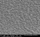
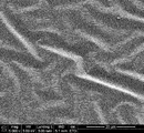
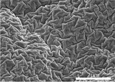
- 6 is an observation image obtained by observing the outermost surface of the laminated body having irregularities in Example 3 with a scanning microscope (SEM) at a magnification of 5,000 times.
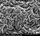
- 6 is an observation image obtained by observing the outermost surface of the laminated body having irregularities in Example 3 with a scanning microscope (SEM) at a magnification of 50,000 times.
- 6 is an observation image obtained by observing the outermost surface of the laminated body having irregularities in Example 5 with a scanning microscope (SEM) at a magnification of 5,000 times.
- 6 is an observation image obtained by observing the outermost surface of the laminated body having irregularities in Example 5 with a scanning microscope (SEM) at a magnification of 50,000 times.
- 6 is an observation image obtained by observing the outermost surface of the laminated body having irregularities in Example 9 with a scanning microscope (SEM) at a magnification of 5,000 times.
- 6 is an observation image obtained by observing the outermost surface of the laminated body having irregularities in Example 9 with a scanning microscope (SEM) at a magnification of 50,000 times.
- 6 is an observation image obtained by observing the outermost surface of the laminated body having irregularities in Example 13 with a scanning microscope (SEM) at a magnification of 5,000 times.
- 6 is an observation image obtained by observing the outermost surface of the laminated body having irregularities in Example 13 with a scanning microscope (SEM) at a magnification of 50,000 times.
- 6 is an observation image obtained by observing the outermost surface of the laminated body having irregularities in Example 17 with a stereomicroscope.
- 6 is an observation image obtained by observing the outermost surface of the laminated body having irregularities in Example 17 with a scanning microscope (SEM) at a magnification of 5,000 times.
- 6 is an observation image obtained by observing the outermost surface of the laminated body having irregularities in Example 17 with a scanning microscope (SEM) at a magnification of 50,000 times. It is an observation image which observed the outermost surface of the laminated body having unevenness in Comparative Example 1 by magnifying 5,000 times with a scanning microscope (SEM). It is an observation image which observed the outermost surface of the laminated body having unevenness in Comparative Example 1 by magnifying 50,000 times with a scanning microscope (SEM).
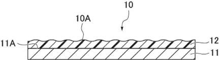
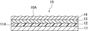
- the laminate 10 according to the first embodiment of the present invention has, for example, as shown in FIGS. 1 to 3, a base material 11 and a resin layer 12 provided on at least one surface 11A of the base material 11.
- the resin layer 12 is formed from a thermosetting or active energy ray-curable resin composition.
- the laminated body 10 no other layer is provided on the resin layer 12, and as shown in FIG. 1, the resin layer 12 becomes the outermost surface 10A of the laminated body 10 on one surface 11A side of the base material 11. You may. Further, the laminated body 10 preferably has a cover layer 13 provided on the resin layer 12 as shown in FIGS. 2 and 3, and further overcovers the laminated body 10 on the cover layer 13 as shown in FIG. Layer 14 may be provided. When the cover layer 13 is provided and the overcover layer 14 is not provided on the cover layer 13, the cover layer 13 constitutes the outermost surface 10A of the laminated body 10, as shown in FIG. When the overcover layer 14 is further provided on the cover layer 13, the overcover layer 14 constitutes the outermost surface 10A of the laminated body 10, as shown in FIG.
- the resin layer 12 may be formed so as to be in direct contact with the base material 11, but a layer such as an adhesive layer may be appropriately provided between the resin layer 12 and the base material 11.
- a layer such as an adhesive layer
- the laminated body of the present embodiment will be described in more detail.
- the laminate 10, the base material 11, the resin layer 12, the cover layer 13 and the overcover layer 14 in the present embodiment are referred to as "laminate (I)", “base material (I)” and “resin layer”, respectively. It may be referred to as “(I)”, “cover layer (I)", or “overcover layer (I)".
- the outermost surface 10A of the laminated body (I) 10 on one surface 11A side of the base material (I) 11 has irregularities including a wrinkle structure. Since the laminate (I) 10 has irregularities including a wrinkle structure, it can be applied to various applications (adhesion prevention, light transmission, etc.) utilizing fine irregularities on the surface. For example, if a liquid-repellent material is selected as the layer constituting the outermost surface 10A of the laminate (I) 10, the contents are less likely to adhere to the surface of the laminate (I) and can be applied to a packaging material. Further, if the adhesiveness of cells, bacteria, etc. can be reduced by controlling the uneven structure, it can be applied to sanitary materials. Furthermore, by having the unevenness including the wrinkle structure, good cloudiness can be exhibited, and for example, the haze and light transmission of the laminated body (I) can be controlled.
- the wrinkle structure is a wrinkle shape generated by buckling of the resin layer (I) 12, and is different from the uneven shape having many point-like protrusions such as the uneven shape formed by particles. be.
- the wrinkle structure is spontaneously formed, a mold such as a transfer sheet is unnecessary.
- FIG. 4 shows a schematic diagram of the wrinkle structure.
- the wrinkle structure is composed of a plurality of undulations c, and the plurality of undulations c have a ridge portion a and a groove portion b, respectively.
- the ridge portion a and the groove portion b have a straight line, a curved line, or a combination thereof, respectively.
- the ridge a is irregularly formed.
- the ridge portion a may be formed continuously or discontinuously.
- the wrinkle structure is formed by applying a compressive stress along the plane direction to the resin layer (I) 12.
- the compressive stress is applied along a number of directions along the plane direction, whereby the ridge portion a and the groove portion b are irregularly formed.
- the presence or absence of the wrinkle structure can be confirmed by a microscope such as a scanning electron microscope (SEM) at a magnification of, for example, about 1,000 to 100,000 times on the outermost surface of the laminate (I) (FIGS. 6 to 12, 14 and 16). ⁇ 18).
- SEM scanning electron microscope
- the presence or absence of the wrinkle structure can also be confirmed by a three-dimensional image obtained by a three-dimensional non-contact surface shape measuring machine or the like.
- the ridge portion a and the groove portion b appear to form a waviness c.
- the swell c is preferably observed in either a square or rectangular observation image having a side of, for example, 3 to 500 ⁇ m, preferably about 4 to 100 ⁇ m.
- the ridges a forming the wrinkle structure are irregular, and the waviness c also appears in a cycle on the order of a micrometer. Therefore, as shown in FIGS. 6 to 12, 14 and 16 to 18, the waviness c formed by the ridges a and the grooves b is in multiple directions such as the vertical direction, the horizontal direction, and the diagonal direction in the above observation image.
- the top of the ridge portion a and the bottom of the groove portion b appear a plurality of times (for example, five times or more).
- the period of the swell c is typically not constant, and therefore the distance between the tops of the ridges a, the distance between the bottoms of the grooves b, and the like are also not constant.
- the “period of swell c” refers to the distance d between the apex of the ridge portion a and the apex of the ridge portion a adjacent to the groove portion b adjacent to the ridge portion a. say.
- the wrinkle structure may have an embodiment having two or more wrinkle structures (hereinafter, also referred to as “higher-order wrinkle structures”) having different swell periods.
- the wrinkle structure may include a primary wrinkle structure and a secondary wrinkle structure having a smaller swell period than the primary wrinkle structure.
- FIG. 5 shows a schematic view when a primary wrinkle structure and a secondary wrinkle structure are included.
- the primary wrinkle structure is composed of a plurality of undulations c
- the secondary wrinkle structure is a plurality of ridges a and grooves b constituting the plurality of undulations c having a period smaller than that of the undulations c. It is composed of swell c'.
- the wrinkle structure is a primary wrinkle structure and a secondary wrinkle structure formed by finer ridges a'and b'in each of the relatively large ridges a and grooves b forming the primary wrinkle structure. And should have.
- having a secondary wrinkle structure in addition to the primary wrinkle structure makes it possible to form a pseudo-fractal surface.
- Whether or not it has a primary and secondary wrinkle structure can be determined by whether or not undulations appear in both of the two observation images observed at different magnifications. For example, even if the ratio (Y / X) of the magnification (Y) of the other observation image to the magnification (X) of one observation image is 10 or more (Y> X), the swell in both observation images. Is observed, it can be determined that there are primary and secondary wrinkle structures.
- the wrinkle structure may include a primary wrinkle structure, a secondary wrinkle structure having a smaller swell period than the primary wrinkle structure, and a tertiary wrinkle structure having a larger swell period than the primary wrinkle structure.
- Whether or not the image has a primary, secondary and tertiary wrinkle structure can be determined by whether or not undulations appear in all three observation images observed at different magnifications.
- the magnification (X) of the first observation image, the magnification (Y) of the second observation image, and the magnification (Z) of the third observation image are 10X ⁇ Y and 10Y ⁇ Z.
- the above-mentioned waviness is observed in all the observed images, it can be determined that there are primary, secondary and tertiary wrinkle structures.
- Sk is a parameter indicating the degree of bias of the unevenness of the surface.
- This degree of bias Sk represents the mean square of Z (x, y) on the reference plane made dimensionless by the cube of the root mean square height Sq, and means the skewness. It is a numerical value that represents the symmetry of the peaks and valleys centered on the average plane. Therefore, when the degree of deviation Sk ⁇ 0, it means that the deviation is biased downward with respect to the average line, that is, there are more concave valleys than convex peaks.
- the wrinkle structure of the outermost surface 10A of the laminated body (I) 10 is a wrinkle shape formed by buckling of the resin layer (I) 12. Therefore, the symmetry between the convex peaks and the concave valleys is higher than that of the uneven shape formed by the particles. Therefore, it is considered that the Ssk of the wrinkle structure of the laminated body (I) 10 is closer to 0 than the Ssk of the uneven shape formed by the particles.
- the absolute value of Sk on the outermost surface 10A of the laminated body (I) 10 is preferably 5 or less, more preferably 3 or less, further preferably 1 or less, and 0. It is even more preferably 8 or less. Above all, it is preferably 0.5 or less, more preferably 0.3 or less, and further preferably 0.1 or less.
- Sk is a parameter based on ISO25178, and can be calculated by, for example, the following method.
- a three-dimensional non-contact surface shape measuring device (VertScan2.0 R5200G manufactured by Ryoka System Co., Ltd.), measure with the device CCD camera SONY HR-50 1/3 inch (objective lens 10 times, wavelength filter 530 nm white).
- Mode Wave
- measurement area 469.17 ⁇ m ⁇ 351.89 ⁇ m
- the undulation component is removed by polynomial fourth-order approximation plane correction on the shooting screen with the attached analysis software (VS-Viewer Version 51.3).
- it can be calculated by performing an interpolation process (a process of supplementing a pixel whose height data could not be acquired with height data calculated from surrounding pixels).
- the outermost surface 10A of the laminated body (I) preferably has a specific surface area (S / A) of 1.005 or more.
- S / A a specific surface area of 1.005 or more.
- the specific surface area (S / A) is more preferably 1.01 or more, further preferably 1.05 or more, and even more preferably 1.1 or more.
- the specific surface area (S / A) is not particularly limited, but is preferably 2 or less, more preferably 1.7 or less, in order to prevent the ridges of the wrinkle structure from becoming too high and reducing the structural strength. It is preferable, and 1.5 or less is more preferable.
- the specific surface area (S / A) can be calculated by S / A, where A is the area of the measurement target area and S is the surface area of the measurement target area on the outermost surface 10A. More specifically, it can be obtained by the method shown in Examples described later.
- the Sa (arithmetic mean roughness) of the outermost surface 10A of the laminated body (I) is not particularly limited, but is, for example, 50 nm or more. By setting Sa to 50 nm or more, it means that unevenness is sufficiently formed by the wrinkle structure, and when applied to an optical material, for example, the fogging property can be adjusted. From these viewpoints, Sa (arithmetic mean roughness) is preferably 100 nm or more, more preferably 200 nm or more, and further preferably 300 nm or more.
- Sa is not particularly limited, but from the viewpoint of maintaining the physical strength of the wrinkle structure, it is preferably 3000 nm or less, more preferably 2000 nm or less, still more preferably 1800 nm or less, still more preferably 1600 nm or less. Above all, it is preferably 1300 nm or less.
- the Sz (maximum height) of the outermost surface 10A of the laminated body (I) is not particularly limited, but is preferably 4000 nm or more, more preferably 5000 nm or more, and further preferably 6000 nm or more.
- Sz is equal to or higher than these lower limit values, it means that sufficient buckling has progressed and a wrinkle structure having high ridges has been formed. Therefore, for example, when applied to an optical material, the fogging property can be adjusted.
- the Sz (maximum height) is not particularly limited, but is preferably 20000 nm or less, more preferably 15000 nm or less, still more preferably 13000 nm or less, still more preferably 10000 nm or less, from the viewpoint of maintaining the physical strength of the wrinkle structure.
- Sa and Sz can be measured by the method shown in Examples described later.
- the base material (I) used for the laminate (I) is not particularly limited, and examples of the material include an organic substance such as a resin, an inorganic substance such as a metal or a metal oxide, and an organic-inorganic composite.
- Examples of the shape of the base material (I) include a sheet, a film, a substrate, a three-dimensional shape product including a container and a tube, and the like.
- the base material (I) is preferably made of a resin, more preferably a resin film or a plastic container. According to the manufacturing method described later, the laminated body (I) can easily form irregularities on a base material having a complicated shape, the inside of a container, and the like.
- the resin film used as the base material (I) is not limited in material and composition as long as it is a film having necessary and sufficient rigidity.
- the resin film may have a single-layer structure or a multi-layer structure. When the resin film has a multi-layer structure, it may have a multi-layer structure of 4 layers or more as long as the effect of the present invention is not impaired other than the 2-layer and 3-layer structure.
- Resins used for resin films include polyester, polyarylates, polyethersulfone, polycarbonate, polyetherketone, polysulfone, polyphenylene sulfide, polyester-based liquid crystal polymer, triacetyl cellulose, cellulose derivative, polypropylene, polyamides, polyimide, poly. Cycloolefins and the like can be exemplified. These resins may be used alone in the resin film, or may be used in combination of two or more. When the resin film has multiple layers, the resins constituting each layer may be of different types or may be of the same type. Further, the resin film may be formed into a single layer or a multilayer by combining two or more kinds of the above resins to form each layer.
- the main component resin of each layer is a polyester film.
- the "main component resin” means the resin having the highest content ratio among the resins constituting the polyester film, for example, 50% by mass or more, preferably 70% by mass or more of the resins constituting the polyester film. More preferably, it is a resin that accounts for 80% by mass or more (including 100% by mass).
- Each layer of the resin film may contain a resin other than polyester or a component other than the resin as long as it contains polyester as the main component resin.
- the polyester may be a homopolyester or a copolymerized polyester.
- it is preferably obtained by polycondensing an aromatic dicarboxylic acid and an aliphatic glycol.
- aromatic dicarboxylic acid include terephthalic acid and 2,6-naphthalenedicarboxylic acid.
- aliphatic glycol include ethylene glycol, diethylene glycol, 1,4-cyclohexanedimethanol and the like.
- examples of the dicarboxylic acid component of the copolymerized polyester include one or more of isophthalic acid, phthalic acid, terephthalic acid, 2,6-naphthalenedicarboxylic acid, sebacic acid and the like, and ethylene as the glycol component.
- One or more kinds such as glycol, diethylene glycol, propylene glycol, butanediol, 4-cyclohexanedimethanol, neopentyl glycol and the like can be mentioned.
- polyester examples include polyethylene terephthalate (PET), polyethylene naphthalate (PEN), polybutylene terephthalate (PBT), and polybutylene terephthalate (PBN).
- PET polyethylene terephthalate
- PEN polyethylene naphthalate
- PBT polybutylene terephthalate
- PBN polybutylene terephthalate
- PET and PEN are preferable, and PET is more preferable.
- the resin film may contain particles for the purpose of forming fine uneven structures on the film surface to impart various functions and for the main purpose of preventing scratches in each step.
- the type of the particles is not particularly limited as long as the particles can be easily slippery.
- inorganic particles such as silica, calcium carbonate, magnesium carbonate, barium carbonate, calcium sulfate, calcium phosphate, magnesium phosphate, kaolin, aluminum oxide, titanium oxide, acrylic resin, styrene resin, urea resin, phenol resin, epoxy resin, benzoguanamine.
- organic particles such as resin. These may be used alone or in combination of two or more of them.
- precipitated particles in which a part of a metal compound such as a catalyst is precipitated and finely dispersed can also be used.
- the shape of the particles is not particularly limited. For example, it may be spherical, lumpy, rod-shaped, flat-shaped, or the like. Further, the hardness, specific gravity, color and the like of the particles are not particularly limited. Two or more kinds of these series of particles may be used in combination, if necessary.
- the average particle size of the particles is preferably 5 ⁇ m or less, more preferably 0.01 ⁇ m or more and 3 ⁇ m or less, and further preferably 0.5 ⁇ m or more and 2.5 ⁇ m or less.
- the content of the particles is preferably 5% by mass or less, more preferably 0.0003% by mass or more and 3% by mass or less, and further preferably 0.01% by mass or more and 2% by mass or less with respect to 100% by mass of the resin film. be.
- the method of adding particles to the resin film is not particularly limited, and a conventionally known method can be adopted.
- it can be added in the process of producing the resin component.
- polyester film it can be added at any stage in the production of polyester. It is preferable to add the ester after the esterification or transesterification reaction is completed.
- antioxidants can be added to the resin film.
- antistatic agents can be added to the resin film.
- heat stabilizers can be added to the resin film.
- lubricants can be added to the resin film.
- the thickness of the resin film is not particularly limited as long as it can be formed as a film, but is preferably 12 ⁇ m or more and 250 ⁇ m or less, more preferably 25 ⁇ m or more and 250 ⁇ m or less, and further preferably 50 ⁇ m or more and 200 ⁇ m or less.
- the resin film can be formed, for example, by forming the resin composition into a film shape by a melt film forming method or a solution film forming method. In the case of a multi-layer structure, co-extrusion may be performed. Further, it may be uniaxially stretched or biaxially stretched, and a biaxially stretched film is preferable from the viewpoint of rigidity.
- the plastic container used as the base material (I) is not particularly limited, and may be a bottomed cylindrical container or a container having an elliptical cross section with a rounded bottom. Further, the container may have a substantially rectangular cross section with the mouth portion reduced in diameter with respect to the body portion. The diameter of the container may be reduced.
- plastic material constituting the plastic container examples include polyethylene terephthalate resin (PET), polyethylene terephthalate copolymer resin (copolymer resin using cyclohexanedimethanol or the like as a comonomer instead of ethylene glycol as the alcohol component of polyester).
- PET polyethylene terephthalate resin
- copolymer resin using cyclohexanedimethanol or the like as a comonomer instead of ethylene glycol as the alcohol component of polyester examples include polyethylene terephthalate resin (PET), polyethylene terephthalate copolymer resin (copolymer resin using cyclohexanedimethanol or the like as a comonomer instead of ethylene glycol as the alcohol component of polyester).
- Polybutylene terephthalate resin polyethylene naphthalate resin, polyethylene resin, polypropylene resin (PP), cycloolefin copolymer resin (COC, cyclic olefin copolymer), ionomer resin, poly-4-methylpentene-1 resin, polymethacryl Methyl acid acid resin, polystyrene resin, ethylene-vinyl alcohol copolymer resin, acrylonitrile resin, polyvinyl chloride resin, polyvinylidene chloride resin, polyamide resin, polyamideimide resin, polyacetal resin, polycarbonate resin (PC), polysulfone resin, tetrafluoride Examples thereof include ethylene resin, acrylonitrile-styrene resin, acrylonitrile-butadiene-styrene resin, and among these, polyethylene terephthalate resin (PET) and polycarbonate resin (PC) are preferable in terms of versatility.
- PET polyethylene terephthalate resin
- the base material other than the resin is not particularly limited as long as the resin layer (I) described later can be fixed on the base material (I), and examples thereof include metals, semimetals, ceramics, and composite materials.
- the metal include aluminum, copper, silver, gold, iron, nickel and the like, and these metals may be used alone or as an alloy, and aluminum, copper, SUS, which is a steel-based material, and the like are preferable.
- the semimetal include silicon and germanium, and these semimetals may be used alone or as an alloy.
- the ceramics include inorganic solid materials such as oxides, carbides, nitrides, and borides, and preferably glass, ceramics, and the like.
- the composite material is a material in which two or more different materials made of resin, metal, semi-metal, ceramic, etc. are integrally combined, and examples thereof include glass fiber reinforced plastic, carbon fiber reinforced plastic, and nanocomposite material.
- a metal container, a glass container and the like are suitable as the base material other than these resins.
- the resin layer (I) is formed from a thermosetting or active energy ray-curable resin composition (hereinafter, may be simply referred to as “curable resin composition”).
- the resin layer (I) is a cured product formed by curing the curable resin composition. When the curable resin composition is cured, it can be easily adhered to the base material (I), the cover layer (I), and the like. Further, when the resin layer (I) is surface-treated by a dry process in a semi-cured state or the like as described later, the resin layer (I) can buckle and form a wrinkle structure following the compressive stress applied along the surface direction.
- thermosetting resin composition When the curable resin composition is a thermosetting resin composition, the thermosetting resin composition preferably contains a binder resin, and more preferably contains a binder resin and a curing agent. By containing the binder resin and the curing agent, the thermosetting resin composition is likely to buckle when compressive stress is applied while ensuring adhesiveness to the base material (I), the cover layer (I), and the like. It is easy to form a wrinkle structure.
- the binder resin is a thermosetting resin that can be cured by heating, and is a resin that cures in the presence of a curing agent when the thermosetting resin composition contains a curing agent.
- Binder resins include polyester resin, urethane resin, acrylic resin, vinyl alcohol resin, ethylene vinyl alcohol resin, vinyl modified resin, oxazoline group-containing resin, carbodiimide group-containing resin, epoxy group-containing resin, isocyanate group-containing resin, and alkoxyl group. Examples thereof include resins, modified styrene resins, modified silicone resins, and the like, and these can be used alone or in combination of two or more.
- the binder resin may be formed by reacting the binder resins with each other to form the resin layer (I).
- polyester resin urethane resin, acrylic resin, epoxy group-containing resin, and alkoxyl group-containing resin from the viewpoint of adhesion to the base material (I) or the base material (I) and the cover layer (I) and heat resistance and water resistance. It is preferable to use at least one selected from the above alone or in combination of two or more, and an acrylic resin is more preferable.
- the binder resin may be any resin that can be thermally crosslinked such as urethane curing and epoxy curing, and from the viewpoint of reactivity with the isocyanate compound used as a curing agent described later, two hydroxyl groups are contained in one molecule.
- the polyol having the above is preferable, and the acrylic polyol is particularly preferable.
- the acrylic resin examples include (meth) acrylic polymers obtained by polymerizing a polymerizable monomer containing a (meth) acrylic monomer.
- the (meth) acrylic polymer may be a homopolymer, a copolymer, or a copolymer with a polymerizable monomer other than the (meth) acrylic monomer. ..
- the (meth) acrylic monomer is a monomer having a (meth) acryloyl group.
- the polymerizable monomer other than the (meth) acrylic monomer is a monomer having a polymerizable functional group, and the polymerizable functional group has a carbon-carbon unsaturated bond other than the (meth) acryloyl group such as a vinyl group. Examples include functional groups containing.
- the expression (meth) acryloyl group when used in this specification, it means one or both of "acryloyl group” and "methacryloyl group", and the same applies to other similar terms.
- An example is a hydrocarbon-based (meth) acrylate in which a portion other than the above is composed of a hydrocarbon.
- alkyl (meth) acrylate or cyclic alkyl (meth) acrylate is preferable, and methyl (meth) acrylate, ethyl (meth) acrylate, isopropyl (meth) acrylate, n-butyl (meth) acrylate, and isobutyl (meth) acrylate are preferable.
- the constituent unit derived from the hydrocarbon-based (meth) acrylate is preferably, for example, 20% by mass or more and 90% by mass or less, and 30% by mass or more and 80% by mass or less.
- a monomer component other than the hydrocarbon-based (meth) acrylate may be used, and specifically, a hydroxyl group-containing monomer is preferably used.
- the hydroxyl group-containing monomer include 2-hydroxyethyl (meth) acrylate, 2-hydroxypropyl (meth) acrylate, 2-hydroxybutyl (meth) acrylate, 4-hydroxybutyl (meth) acrylate, and 6-hydroxyhexyl (meth).
- Hydroxyalkyl (meth) acrylate such as acrylate can be mentioned.
- the hydroxyl group in the hydroxyl group-containing monomer is a hydroxyl group that does not directly bond to the aromatic ring.
- the acrylic resin is a (meth) acrylic copolymer obtained by copolymerizing the hydrocarbon-based (meth) acrylate and the hydroxyl group-containing monomer.
- a (meth) acrylic copolymer obtained by copolymerizing a hydrocarbon-based (meth) acrylate, a hydroxyl group-containing monomer, and other monomer components (other monomer components) is preferable.
- the (meth) acrylic copolymer can be made into an acrylic polyol containing a plurality of hydroxyl groups.
- the structural unit derived from the hydroxyl group-containing monomer is, for example, preferably 0.5% by mass or more and 80% by mass or less, and more preferably 1% by mass or more and 70% by mass or less.
- a monomer component (other monomer component) other than the hydrocarbon-based (meth) acrylate and the hydroxyl group-containing monomer may be used, and specifically, acrylic acid, methacrylic acid, crotonic acid, and itaconic acid.
- Carboxyl group-containing monomers such as fumaric acid, maleic acid, citraconic acid; amino group-containing monomers such as dimethylaminoethyl (meth) acrylate, dimethylaminoethyl (meth) methacrylate, diethylaminoethyl (meth) acrylate; glycidyl (meth) Acrylate, ⁇ -methylglycidyl (meth) acrylate, o-vinylbenzyl glycidyl ether, m-vinylbenzyl glycidyl ether, p-vinylbenzyl glycidyl ether, ⁇ -methyl-o-vinylbenzyl glycidyl ether, ⁇ -methyl-m-vinyl Epoxy group-containing monomers such as benzyl glycidyl ether, ⁇ -methyl-p-vinylbenzyl glycidyl ether, 3,4-epoxy
- Acrylate compounds such as ether (meth) acrylate (meth) acrylamide, diacetone acrylamide, and N-methylol acrylamide; (meth) acrylonitrile; styrene derivatives such as styrene, ⁇ -methylstyrene, divinylbenzene, and vinyltoluene; vinyl chloride, chloride. Examples include various vinyl halides such as vinylidene.
- a monomer having a functional group having an ultraviolet absorbing function may be used from the viewpoint of improving the light resistance of the resin layer (I).
- UV-absorbing functional group such as a benzotriazole skeleton, a benzophenone skeleton, a triazine skeleton, and a hindered amine skeleton
- polymerizable functional group such as a (meth) acryloyl group
- the content of the structural unit derived from other monomer components is, for example, 50% by mass or less, preferably 40% by mass, in the (meth) acrylic polymer. It is as follows.
- the lower limit is not particularly limited, and may be 0% by mass or more.
- Each of the above-mentioned monomer components is a monofunctional monomer having one polymerizable functional group in the molecule as illustrated above.
- a polyfunctional monomer having two or more polymerizable functional groups may be appropriately contained as long as the effects of the present invention are not impaired.
- the curing agent a compound that can be cured by reacting with the binder resin may be used, but from the viewpoint of curability with the binder resin, an isocyanate compound is preferably used.
- the binder resin is preferably having a functional group capable of reacting with an isocyanate group, and examples of the functional group include a hydroxyl group, a carboxyl group, and an amino group, from the viewpoint of reactivity with the isocyanate group. , A hydroxyl group is preferable.
- an isocyanate compound as a curing agent and a polyol as a binder resin
- the acrylic resin is preferably an acrylic polyol containing a plurality of hydroxyl groups in one molecule as described above. ..
- the isocyanate compound is preferably an aromatic or aliphatic diisocyanate or a trivalent or higher valent polyisocyanate.
- the isocyanate compound include tetramethylene diisocyanate, hexamethylene diisocyanate, toluene diisocyanate, diphenylmethane diisocyanate, hydride diphenylmethane diisocyanate, xylylene diisocyanate, hydride xylylene diisocyanate, isophorone diisocyanate, cyclohexane diisocyanate, dicyclohexyl diisocyanate, or three amounts thereof. You can use your body.
- excess amounts of these isocyanate compounds and low molecular weight active hydrogen compounds such as ethylene glycol, propylene glycol, trimethylolpropane, glycerin, sorbitol, biuret, cyanuric acid, ethylenediamine, monoethanolamine, diethanolamine and triethanolamine,
- a terminal isocyanate group-containing compound obtained by reacting with an active hydrogen polymer compound such as a polyester polyol, a polyether polyol, and a polyamide may be used.
- the blending ratio of the binder resin and the curing agent may be adjusted by adjusting the ratio of the number of hydroxyl groups of the binder resin to the number of isocyanate groups of the curing agent (number of isocyanate groups) /.
- Number of hydroxyl groups is preferably 0.05 or more and 30 or less, more preferably 0.1 or more and 20 or less, and further preferably 0.2 or more and 15 or less.
- the resin layer (I) When the resin layer (I) is formed from a thermosetting resin composition, the resin layer (I) preferably contains a resin having a urethane bond. Flexibility is ensured by using a resin having a urethane bond, and it becomes easy to buckle due to the compressive stress generated when the surface is treated by the dry process.
- the urethane bond is preferably formed by at least one of the reaction between the binder resins and the reaction between the binder resin and the curing agent, and more preferably the urethane bond is formed by the reaction between the binder resin and the curing agent.
- the active energy ray-curable resin composition contains a photopolymerizable compound.
- the photopolymerizable compound is a compound that can be polymerized by being irradiated with active energy rays. The details of the active energy ray are as described in the manufacturing method described later.
- the resin component of the resin layer (I) formed by the active energy ray-curable resin composition is a prepolymer such as epoxy (meth) acrylate, urethane (meth) acrylate, polyester (meth) acrylate, and acrylic (meth) acrylate.
- a mixture with a photopolymerizable monomer or a photopolymerizable monomer can be used alone.
- the photopolymerizable monomer is not particularly limited as long as it is a compound having a radically polymerizable group, and examples thereof include a polyfunctional photopolymerizable monomer.
- the number of radically polymerizable groups contained in one molecule of the polyfunctional photopolymerizable monomer is not particularly limited, and may be 2 or more.
- Examples of the radically polymerizable group include functional groups containing carbon-carbon unsaturated bonds such as (meth) acryloyl group and vinyl group, and among them, (meth) acryloyl group is preferable.
- Examples of the photopolymerizable monomer include a polyfunctional (meth) acrylate having an aromatic ring, and specifically, a polyfunctional (meth) having a benzene ring, a naphthalene ring, an anthracene ring, a fluorene ring, a phenanthrene ring, a phenalene ring, and the like.
- Acrylate is preferable, and among these, fluorene-based polyfunctional (meth) acrylate having a fluorene ring is preferable.
- fluorene-based polyfunctional (meth) acrylate examples include 9,9-bis [4- (2- (meth) acryloyloxyethoxy) phenyl] fluorene and 9,9-bis [4- (2- (meth) acryloyl) acrylate.
- various polyfunctional (meth) acrylates can be used in addition to the polyfunctional (meth) acrylate having an aromatic ring, and ethylene glycol di (meth) acrylate and polyethylene glycol di (meth) can be used.
- a polyfunctional (meth) acrylate having an aromatic ring is preferable, and the polyfunctional (meth) acrylate having an aromatic ring may be used in combination with another photopolymerizable compound.
- the photopolymerizable monomer may be used alone or in combination with a monofunctional photopolymerizable compound described later.
- the photopolymerizable monomer is not limited to polyfunctionality, and may be a monofunctional photopolymerizable monomer.
- the monofunctional photopolymerizable monomer may be used alone, or may be used in combination with the polyfunctional photopolymerizable monomer as described above.
- the monofunctional photopolymerizable monomer includes alkyl (meth) acrylate, cyclic alkyl (meth) acrylate, (meth) acrylate having an aromatic ring, hydroxyl group-containing monomer, carboxyl group-containing monomer, amino group-containing monomer, epoxy group-containing monomer, and acrylamide. Examples include system compounds, (meth) acrylonitrile, styrene derivatives, vinyl halides and the like. As these specific compounds, those exemplified in the above-mentioned (meth) acrylic polymer can be appropriately used.
- the curable resin composition contains a photopolymerizable compound, it preferably further contains a photopolymerization initiator.
- the resin layer (I) precursor can be easily cured by irradiating the resin layer (I) precursor with active energy rays as described later.
- the photopolymerization initiator include benzyl, benzophenone and its derivatives, thioxanthones, benzyl dimethyl ketals, ⁇ -hydroxyalkylphenone, ⁇ -hydroxyacetophenone, hydroxyketone, aminoalkylphenone, and acylphosphine oxide. , Oxime ester compound and the like. Among them, ⁇ -hydroxyalkylphenones are preferable because they are less likely to cause yellowing during curing and a transparent cured product can be obtained.
- the content of the photopolymerization initiator is preferably in the range of 0.05 parts by mass or more and 5 parts by mass or less, more preferably 0.2 parts by mass or more and 3 parts by mass with respect to 100 parts by mass of the curable resin composition.
- the range is as follows. When the content of the photoinitiator is 0.05 parts by mass or more, the desired starting effect can be obtained, and when the content of the photoinitiator is 5 parts by mass or less, irradiation with active energy rays is performed. As a result, the curable resin composition is not over-cured, and it becomes easier to keep it in a semi-cured state.
- the mode in which the curable resin composition has either thermosetting property or active energy ray curability has been described, but heat and active energy rays that can be cured by both heat and active energy rays have been described.
- It may be a curable resin composition.
- the curable resin composition may contain both the binder resin and the photopolymerizable compound.
- the curable resin composition is, if necessary, an internal defoaming agent, a coatability improver, a thickener, an organic lubricant, an ultraviolet absorber, an antioxidant, and foaming, as long as the gist of the present invention is not impaired. It may contain agents, dyes, pigments, inorganic particles, organic particles and the like. These additives may be used alone or in combination of two or more as required.
- the thickness (tb) of the resin layer (I) may be adjusted according to the level difference of the unevenness to be formed and the application, and is not limited, but is preferably 0.1 ⁇ m or more and 15 ⁇ m or less. If it is 15 ⁇ m or less, it can be prevented from peeling from the base material (I) due to the internal stress of the resin layer (I) itself. When the thickness is 0.1 ⁇ m or more, the thickness of the resin layer (I) can be kept uniform, and the wrinkle structure can secure a certain roughness or more.
- the thickness (tb) of the resin layer (I) is more preferably 0.5 ⁇ m or more, further preferably 1 ⁇ m or more, still more preferably 2 ⁇ m or more, and preferably 10 ⁇ m or less, more preferably. Is 7 ⁇ m or less.
- the thickness of the resin layer (I) and the cover layer (I) and the overcover layer (I) described later can be measured by step measurement using a fine shape measuring machine, or a scanning electron microscope (SEM) and / or a transmission electron microscope.
- SEM scanning electron microscope
- the maximum thickness (convex peak) and the minimum thickness (concave valley) can be measured by cross-sectional observation using (TEM), and can be obtained by averaging these values.
- cover layer (I) On the resin layer (I).
- the cover layer (I) may be formed as a layer that comes into direct contact with the resin layer (I).
- Specific examples of the cover layer (I) include an inorganic substance-containing layer and a cover resin layer. Among these, the inorganic substance-containing layer is preferable.
- the inorganic substance-containing layer constituting the cover layer (I) may be referred to as an inorganic substance-containing layer (1) in order to distinguish it from the inorganic substance-containing layer constituting the overcover layer (I) described later. ..
- the inorganic substance-containing layer (1) is a layer formed of an inorganic substance and containing the inorganic substance as a main component.
- the inclusion of an inorganic substance as a main component means that the inorganic substance accounts for 50% by mass or more, particularly 70% by mass or more, particularly 80% by mass or more, particularly 90% by mass or more, and particularly 100% by mass of the inorganic substance-containing layer. do.
- the inorganic substance-containing layer (1) may be formed of an inorganic substance having good adhesion to the resin layer (I). Further, it is preferable that the inorganic substance-containing layer (1) is formed by using a material that can be easily formed on the resin layer (I) by a dry process.
- the inorganic substance-containing layer (1) is preferably formed as an inorganic substance from at least one selected from diamond-like carbon (DLC), metal, metal oxide, metal nitride, metal carbide, or a composite thereof.
- the metal referred to here also includes so-called metalloids such as silicon, boron, and germanium.
- the metals constituting the metal, metal oxide, metal nitride, metal carbide, or a composite thereof include silicon, aluminum, zinc, titanium, niobium, gold, silver, copper, and indium. , Tin, nickel and the like, among which silicon and niobium are preferable, and silicon is more preferable.
- the inorganic substances used in the inorganic substance-containing layer (1) are silicon-based compounds such as silicon oxide, silicon nitride, silicon oxide nitride, silicon oxide, silicon oxide carbide, silicon carbide, fluorine-containing silicon oxide, and fluorine-containing silicon carbide.
- silicon-based compounds such as silicon oxide, silicon nitride, silicon oxide nitride, silicon oxide, silicon oxide carbide, silicon carbide, fluorine-containing silicon oxide, and fluorine-containing silicon carbide.
- Aluminum compounds such as aluminum oxide, aluminum nitride, aluminum oxide and aluminum oxide, niobium compounds such as niobide oxide, zinc compounds such as zinc oxide, titanium compounds such as titanium oxide, diamond-like carbon, and fluorine-containing diamonds. It is preferably at least one selected from like carbon and conductive oxides such as ITO and IZO.
- the inorganic substance-containing layer (1) can increase the hardness of the laminated body (I) and improve the durability of the laminated body (I), among the above-mentioned inorganic substances, diamond-like carbon (DLC), silicon oxide, etc.
- a layer containing at least one of niobium oxide, silicon carbide, and silicon carbide is preferable, and a layer containing at least one of DLC, silicon oxide, and niobium oxide is more preferable.
- the inorganic substance-containing layer is more preferably a DLC layer formed of diamond-like carbon (DLC).
- the cover resin layer is preferably formed on the resin layer (I) by a dry process described later.
- the cover resin layer is a layer formed of a resin component and containing the resin component as a main component.
- the fact that the resin component is contained as the main component means that the resin component accounts for 50% by mass or more, particularly 70% by mass or more, particularly 80% by mass or more, particularly 90% by mass or more, and 100% by mass in particular, of the cover resin layer. Means that.
- the resin component used for the cover resin layer a resin component that can form a film on the resin layer (I) by a dry process can be preferably used.
- the resin component include fluorine-based resin, polyethylene, polystyrene, and the like, and among them, a fluorine-based resin layer formed of a fluorine-based resin is preferable.
- the fluororesin By using the fluororesin, the cover resin layer can be easily formed on the resin layer (I) by the dry process.
- the fluorine-based resin when the cover resin layer is the outermost surface, it becomes easy to impart chemical resistance, slipperiness or liquid repellency to the laminate (I).
- the fluorine-based resin include polytetrafluoroethylene and tetrafluoroethylene-ethylene copolymer.
- the cover layer (I) is preferably formed by a dry process as described later, but does not necessarily have to be formed by a dry process.
- unevenness including a wrinkle structure is formed in the resin layer (I) in advance by another dry process as shown in Example 13, and then the cover layer (I) is formed. Should be formed.
- the cover layer (I) is formed in addition to the dry process as described above, other than the above can be used as the inorganic substance-containing layer, the inorganic substance used for the cover resin layer, and the resin component.
- those exemplified as resin components that can be used for the overcover layer (I) described later may be used.
- the thickness (ta) of the cover layer (I) is preferably 5 nm or more and 300 nm or less.
- an appropriate film stress is generated when the film is formed by a dry process, and an appropriate compressive stress is applied to the resin layer (I).
- the thickness (ta) of the cover layer (I) is more preferably 10 nm or more and 250 nm or less, and further preferably 20 nm or more and 200 nm or less.
- the ratio (ta / tb) of the thickness (ta, unit: nm) of the cover layer (I) to the thickness (tb, unit: ⁇ m) of the resin layer (I) is preferably 0.1 or more and 3500 or less. ..
- the thickness ratio is more preferably 1 or more and 500 or less, further preferably 2 or more and 400 or less, and further preferably 5 or more and 250 or less.
- the overcover layer (I) is a layer further provided on the cover layer (I).
- Examples of the overcover layer (I) include an inorganic substance-containing layer and an overcover resin layer.
- the overcover layer (I) can be provided with various functions on the outermost surface of the laminated body (I) by appropriately changing the material.
- the overcover layer (I) may be composed of one single layer or two or more layers may be laminated. When two or more overcover layers (I) are provided, for example, a combination of one or more inorganic substance-containing layers and one or more overcover resin layers may be used.
- the inorganic substance-containing layer constituting the overcover layer (I) is referred to as the inorganic substance-containing layer (2) in order to distinguish it from the inorganic substance-containing layer (1) constituting the cover layer (I) described above. There is.
- the inorganic substance-containing layer (2) is a layer formed of an inorganic substance and containing the inorganic substance as a main component.
- the inorganic substance-containing layer (2) is preferably different in composition from the inorganic substance-containing layer (1), and is contained in, for example, the inorganic substance-containing layer (1). It is preferable to contain an inorganic substance different from the inorganic substance.
- the inorganic substance-containing layer (2) may be formed of an inorganic substance having good adhesion to the cover layer (I). Further, the inorganic substance-containing layer (2) is preferably a material that can be formed on the cover layer (I) by a dry process, but may be a material that can be formed on the cover layer (I) by a method other than the dry process.
- the inorganic substance-containing layer (2) may be formed from a thin film containing at least one selected from diamond-like carbon (DLC), metal, metal oxide and metal nitride, metal carbide, or a composite thereof as an inorganic substance. preferable.
- the metals constituting the metal, metal oxide, metal nitride, metal carbide, or a composite thereof include silicon, aluminum, zinc, titanium, niobium, gold, silver, copper, and indium. , Tin, nickel and the like, among which silicon and niobium are preferable, and silicon is more preferable.
- the inorganic substances used in the inorganic substance-containing layer (2) are silicon-based compounds such as silicon oxide, silicon nitride, silicon oxide nitride, silicon oxide, silicon oxide carbide, silicon carbide, fluorine-containing silicon oxide, and fluorine-containing silicon carbide.
- silicon-based compounds such as silicon oxide, silicon nitride, silicon oxide nitride, silicon oxide, silicon oxide carbide, silicon carbide, fluorine-containing silicon oxide, and fluorine-containing silicon carbide.
- Aluminum compounds such as aluminum oxide, aluminum nitride, aluminum oxide and aluminum oxide, niobium compounds such as niobide oxide, zinc compounds such as zinc oxide, titanium compounds such as titanium oxide, diamond-like carbon, and fluorine-containing diamonds. It is preferably at least one selected from like carbon and a conductive oxide such as ITO and IZO.
- the inorganic substance-containing layer (2) is preferably a layer containing silicon carbide as an inorganic substance, that is, the inorganic substance-containing layer is preferably a silicon carbide layer using silicon carbide as an inorganic substance.
- silicon carbon By using silicon carbon, the hardness of the outermost surface of the laminated body (I) can be increased, and the heat resistance and durability of the laminated body (I) can be improved.
- the overcover resin layer is a layer formed of a resin component and containing the resin component as a main component.
- the overcover resin layer may have a composition different from that of the cover layer (I), for example, if it contains a resin component different from the resin component contained in the cover resin layer. good.
- the resin component that can be used for the overcover resin layer is not particularly limited as long as it can be adhered to the cover coat layer, and examples thereof include a fluororesin, a silicone resin, an acrylic resin, and an epoxy resin.
- a fluorine-based resin layer using a fluorine-based resin is preferable.
- the fluororesin layer By using the fluororesin layer, it becomes easy to impart chemical resistance, slipperiness or liquid repellency to the laminate (I).
- the specific compounds of the fluororesin are as described in the cover layer (I).
- the overcover resin layer can be formed by a dry process.
- the thickness of the overcover layer (I) is not particularly limited as long as the unevenness of the wrinkle structure formed by the resin layer (I) appears on the outermost surface, but is preferably 5 nm or more and 300 nm or less, more preferably 10 nm or more and 250 nm or less, and more preferably 20 nm. More preferably 200 nm or less.
- the laminated body (I) may be manufactured by any manufacturing method, but the manufacturing method of the laminated body (I) according to an example of the present embodiment includes the following steps 1 to 3.
- Step 1 A curable resin composition is applied to at least one surface of the base material (I) to form a resin layer (I) precursor.
- Step 2 The resin layer (I) precursor formed in step 1 is formed.
- Semi-curing step Step 3 The resin layer (I) precursor semi-cured in step 2 is further subjected to surface treatment by a dry process, and a wrinkle structure is contained on the surface on one surface side of the base material (I). Step of forming unevenness
- step 2 may be omitted as described later, and therefore, in step 3, the surface treatment of the uncured resin layer (I) precursor may be performed.
- each step will be described in more detail.
- a curable resin composition is applied to at least one surface of the base material (I) to form a resin layer (I) precursor.
- the details of the curable resin composition used in step 1 are as described above.
- the curable resin composition may be diluted with a solvent such as water or an organic solvent, if necessary.
- a solvent such as water or an organic solvent
- the amount of the curable resin composition (parts by mass, etc.) described above and the amount of each component constituting the composition mean the solid content standard. ..
- the organic solvent used is not particularly limited, and may be selected from the viewpoint of solubility, dispersibility, etc. according to the composition of the curable resin composition.
- Alcohol-based solvents such as methyl alcohol, ethyl alcohol, and isopropyl alcohol, and dimethyl glycol.
- Ether solvents such as ethylene glycol monoethyl ether, ester solvents such as ethyl acetate, acetate solvents such as propylene glycol monomethyl ether acetate, ketone solvents such as methyl isobutyl ketone and methyl ethyl ketone, aliphatic hydrocarbons such as various alkanes. Examples include system solvents, aromatic hydrocarbon solvents such as toluene, xylene, and benzene. Only one kind of organic solvent may be used, and two or more kinds may be used as appropriate.
- the components constituting the curable resin composition may be dissolved in a solvent or dispersed in the solvent.
- the solid content concentration is, for example, 0.1% by mass or more and 50% by mass or less, preferably 3% by mass or more and 40% by mass or less. It is preferable to adjust to.
- the curable resin composition may be applied by in-line coating.
- In-line coating refers to applying a curable resin composition on a production line on which a resin film is formed.
- heat drying in an oven or unheated drying in a vacuum dryer can be used.
- the surface of the base material (I) to which the curable resin composition is applied may be subjected to surface treatment such as corona treatment, plasma treatment, and UV ozone treatment in advance.
- step 2 the curable resin composition in the resin layer (I) precursor formed in step 1 is put into a semi-cured state.
- semi-cured means a state in which the curable resin composition is not completely cured, and a state in which the curable resin composition is further cured when further irradiated with heat or energy rays. say. Whether or not the curable resin composition is semi-curable is determined by, for example, whether or not the surface of the resin layer (I) precursor is lightly rubbed 50 times with a cotton swab soaked in a solvent to expose the surface of the base material (I). You can check with.
- the surface of the base material (I) is not exposed even if the surface of the resin layer (I) precursor is rubbed.
- the degree of semi-curing can be determined from the number of times the surface of the resin layer (I) precursor begins to decrease and the number of times it is rubbed until the surface of the base material (I) is exposed.
- the solvent for immersing the cotton swab is preferably the same as the solvent obtained by diluting the curable resin composition.
- the purpose of semi-curing is to make the resin layer (I) precursor obtained in step 1 easy to handle before bringing it into the vacuum dry process of step 3, and to control the wrinkle structure formed in step 3.
- the resin layer (I) precursor obtained in step 1 has a strong tack and is difficult to handle, it is preferable to perform a semi-hardening treatment, but if there is no problem in handling, this step 2 is not essential and heating is performed. And energy beam irradiation does not have to be performed.
- the curable resin composition in a semi-cured state, the resin layer (I) precursor is likely to buckle due to the surface treatment by the dry process in step 3, and unevenness including a wrinkle structure is easily formed.
- the resin layer (I) precursor formed in the above step 1 is semi-cured by heating.
- the method of semi-curing the resin layer (I) precursor may be carried out at room temperature as in natural drying, but from a practical point of view, it is preferably carried out by heating such as heat drying.
- the solvent in step 1 is dried by heating, the solvent may also be dried in this step 2.
- the curable resin composition has active energy ray curability, in this step 2, the resin layer (I) precursor formed in step 1 is irradiated with active energy rays to cause the resin layer (I) precursor. Is semi-cured.
- the heating temperature and heating time may be set according to the components contained in the curable resin composition, and are preferably 50 ° C. or higher and 200 ° C. or lower, for example. Heats the resin layer (I) precursor at a temperature of 70 ° C. or higher and 150 ° C. or lower, for example, for a time of 3 seconds or more and 30 minutes or less, preferably 30 seconds or more and 10 minutes or less, more preferably 40 seconds or more and 5 minutes or less. ..
- the active energy rays used are far ultraviolet rays, ultraviolet rays, near ultraviolet rays, rays such as infrared rays, X-rays, and ⁇ -rays.
- electromagnetic waves such as, electron beams, proton rays, neutron rays, etc. can be used, but curing by ultraviolet irradiation is advantageous in terms of curing speed, availability of irradiation equipment, price, and the like.
- the resin layer (I) precursor When the resin layer (I) precursor is semi-cured by ultraviolet irradiation, a high-pressure mercury lamp, an ultra-high pressure mercury lamp, a carbon arc lamp, a metal halide lamp, a xenon lamp, a chemical lamp, and no electrode are used to emit light in the wavelength range of 150 to 450 nm. A discharge lamp, an LED lamp, or the like may be used.
- the ultraviolet may be irradiated such that the resin layer (I) precursor is partially cured, the irradiation amount is not particularly limited, for example, 0.5 ⁇ 5000mJ / cm 2, preferably 1 ⁇ 2000mJ / cm 2 It suffices to irradiate ultraviolet rays with an integrated amount of light.
- step 3 the resin layer (I) precursor semi-cured in step 2 or the uncured resin layer (I) precursor is further surface-treated by a dry process, and one of the base materials (I) is subjected to surface treatment.
- This is a step of forming irregularities including a wrinkle structure on the surface on the surface side.
- the cover layer (I) may be formed by a dry process, but the dry process process may be performed without forming the cover layer (I) and without forming a film.
- the wrinkle structure may have a higher-order wrinkle structure as described above, but the higher-order wrinkle structure may be formed in step 3.
- the dry process is a method of surface-treating a semi-cured resin layer (I) precursor or an uncured resin layer (I) precursor under reduced pressure or in a vacuum.
- the principle of forming irregularities including a wrinkle structure and the principle of forming a higher-order wrinkle structure by surface treatment by a dry process are not clear, but are presumed as follows.
- the resin layer (I) precursor has energy (light from plasma, radiant heat, electrons) due to the dry process treatment. It is considered that the curing proceeds by receiving the energy received from the particles, ions, or incident particles.
- a process in which the resin layer (I) precursor that has received energy from the dry process treatment cures and shrinks as the temperature rises and loses fluidity, and a film stress is generated when the cover layer (I) grows.
- the process goes on at the same time.
- the compressive stress along the plane direction of the resin layer (I) precursor becomes large, and buckling occurs when the resin layer (I) precursor cannot resist the compressive stress, and the wrinkle structure is formed. Presumed to be formed.
- the energy of the dry process treatment also generates compressive stress in the resin layer (I) precursor along the plane direction. It is presumed that buckling occurs and a wrinkle structure is formed when the resin layer (I) precursor cannot resist the compressive stress.
- the cover layer (I) When the cover layer (I) is formed, if the film stress generated during the film formation of the cover layer (I) is large, the first buckling occurs at an early stage and a large swell (primary wrinkle structure) occurs. It is considered that a small swell (secondary wrinkle structure) is generated when the second buckling occurs at the stage where the resin fluidity is slightly lowered after the formation.
- the size of the waviness in the wrinkle structure is the thickness of the resin layer (I) and the cover layer (I), and the resin layer.
- the size of the waviness can be adjusted by appropriately changing the thickness of the resin layer (I) and the cover layer (I), the components contained in the resin layer (I) and the cover layer (I), the curing conditions, and the like. can.
- the surface treatment by the dry process advances the curing of the resin layer (I) precursor as described above, and in step 3, for example, the resin layer (I) may be completely cured.
- the total curing means a state in which curing does not substantially proceed even if the resin layer (I) is heated or irradiated with active energy rays.
- the cover layer (I) it is preferable to form the cover layer (I) by surface treatment by a dry process.
- the cover layer (I) is formed by surface treatment by a dry process, film stress is generated as described above, and it becomes easy to form a wrinkle structure, and further, a higher-order wrinkle structure can be formed.
- the cover layer (I) can be formed while forming the unevenness including the wrinkle structure in the step 3, so that the process can be simplified. Whether or not the dry process treatment has been performed can be determined by observing the cross section with SEM and / or TEM.
- the cover layer (I) is made of a crystalline material
- the dry process treatment is performed if the crystal grain size changes in the thickness direction of the cover layer (I).
- the crystal nuclei formed on the surface of the resin layer (I) grow and the particle size gradually expands, so that the crystal particle size on the surface of the cover layer (I) becomes the largest.
- the crystal grain size tends to decrease as it approaches the resin layer (I).
- such a change in crystal grain size is not observed when the wet treatment of applying a solvent is performed.
- the solvent evaporates in the process of drying the coating film minute voids are likely to be generated over the entire thickness direction of the cover layer (I), and a low-density film is likely to be formed.
- the surface treatment by the dry process includes, for example, chemical vapor deposition (CVD) and physical vapor deposition (PVD).
- the dry process is preferably a process performed under vacuum or reduced pressure.
- the surface treatment is performed under vacuum or reduced pressure, the semi-cured or uncured resin layer (I) precursor is placed in an atmosphere low in oxygen, and the curing is facilitated by the dry process. Therefore, when the dry process is performed under vacuum or reduced pressure, a wrinkle structure is likely to be formed.
- an active energy ray-curable resin composition oxygen inhibition that hinders radical polymerization is suppressed, so that cross-linking easily proceeds.
- the pressure in the dry process performed under vacuum or reduced pressure depends on the method of the dry process, but is, for example, 15 Pa or less, preferably 10 Pa or less, and more preferably 1 Pa or less.
- the lower limit of the pressure in the dry process is not particularly limited, but is, for example, 1 ⁇ 10 -7 Pa in consideration of the performance limit of each device.
- the CVD is not particularly limited, and includes plasma CVD, thermal CVD, cat-CVD (catalytic chemical vapor deposition), and the like, but plasma CVD is preferable.
- plasma CVD By using plasma CVD, it becomes easy to form a wrinkle structure.
- CVD is preferably performed under reduced pressure from the viewpoint of facilitating the formation of a wrinkle structure, and the pressure at the time of forming the cover layer (I) is preferably 15 Pa or less from the viewpoint of the film forming speed and the uneven structure forming property. , More preferably 1 ⁇ 10 ⁇ 2 Pa or more and 10 Pa or less, and further preferably 1 ⁇ 10 -1 Pa or more and 1 Pa or less.
- the output conditions for forming the cover layer (I) are preferably 100 W or more and 1500 W or less, more preferably 300 W or more and 1200 W or less, and further preferably 400 W, from the viewpoint of generating necessary and sufficient film stress in the cover layer (I). It is 1000 W or less.
- the film thickness of the cover layer (I) can be adjusted by a known method. For example, when plasma CVD is used, the output, the pressure of the raw material gas, the concentration of the raw material gas, the plasma generation time, etc. are adjusted. Can be done by When surface treatment is performed by CVD, the cover layer (I) may be crosslinked by electron beam irradiation, if necessary, in order to improve water resistance and durability.
- CVD is preferably used, for example, when forming the inorganic substance-containing layer (1) and the cover resin layer, and in particular, the inorganic substance-containing layer containing DLC as an inorganic substance, and the inorganic substance-containing layer containing silicon carbide and / or silicon oxide as an inorganic substance.
- It can be suitably used when forming a fluorine-based resin layer or the like containing a fluorine-based resin or the like as a resin component.
- PVD examples include vacuum deposition, sputtering, ion plating and the like, and among these, vacuum deposition and sputtering are preferable.
- PVD is suitable, for example, when a metal, niobium oxide, a metal oxide such as silicon oxide, a metal nitride, or the like is used as the inorganic substance to be contained in the inorganic substance-containing layer (1).
- the inorganic substances contained in the inorganic substance-containing layer (1) are metals such as gold, silver, copper and aluminum, metal oxides such as silicon oxide, titanium oxide and aluminum oxide, and fluorides such as calcium fluoride.
- the inorganic substances contained in the inorganic substance-containing layer (1) are metals such as gold, silver, copper and aluminum, titanium oxide, aluminum oxide, niobium oxide, ITO, IZO and the like. It is suitable when the metal oxide of is used.
- the pressure when the cover layer (I) is formed by PVD is preferably 1 ⁇ 10 -7 Pa or more and 20 Pa or less, more preferably 1 ⁇ 10 -6 Pa or more, from the viewpoint of uneven structure forming property and vacuum exhaust capacity. It is 10 Pa or less, more preferably 1 ⁇ 10 -4 Pa or more and 5 Pa or less.
- the raw material for forming the cover layer (I) may be appropriately selected and the dry process may be performed.
- a hydrocarbon or the like may be used as a raw material.
- each compound may be used alone, or two or more kinds may be mixed and used. Further, the raw material gas may be diluted with a rare gas such as argon (Ar) or helium (He) before use.
- a rare gas such as argon (Ar) or helium (He) before use.
- the inorganic substance-containing layer (1) containing DLC may be formed by PVD.
- an organosilane such as tetramethylsilane or hexamethyldisilane may be used as a raw material.
- hydrogen gas may be appropriately mixed with the mixed gas of the silicon component such as silane and disilane and the carbon component such as alkane having 1 to 6 carbon atoms.
- other raw materials may be used as long as silicon carbide can be formed.
- fluorine-based materials such as CF 4 , C 2 F 4 , C 2 F 6 , C 3 F 8 , C 4 F 8 , and C 5 F 8 are used as raw materials. Gas may be used.
- a silicon compound as a raw material (hereinafter, also referred to as "silicon compound raw material”) may be used.
- the silicon compound raw material can be used in any of gas, liquid, and solid states under normal temperature and pressure. In the case of a gas, it can be directly introduced into the reactor (for example, a discharge space). In the case of liquid or solid, it can be vaporized by means such as heating, bubbling, depressurization, and ultrasonic irradiation.
- the solvent may be diluted before use, and the solvent may be an organic solvent such as methanol, ethanol or n-hexane, or a mixed solvent thereof.
- silicon compound raw material examples include silane, tetramethoxysilane, tetraethoxysilane, tetra n-propoxysilane, tetraisopropoxysilane, tetra n-butoxysilane, tetrat-butoxysilane, dimethyldimethoxysilane, dimethyldiethoxysilane, and diethyl.
- the cover layer (I) may not be formed in the surface treatment by the dry process in the step 3.
- the surface treatment when the cover layer (I) is not formed is not particularly limited as long as the resin layer (I) precursor is buckled by the surface treatment to form irregularities including a wrinkle structure, and examples thereof include plasma treatment.
- the plasma treatment is not particularly limited, but may be performed by a method such as vacuum or vacuum plasma treatment, and among these, vacuum plasma treatment is preferable. Further, in the plasma treatment, the gas may be converted into plasma and the plasma treatment may be performed.
- the type of gas used includes, for example, oxygen gas, hydrogen gas, nitrogen gas, or a rare gas such as argon or helium. As the gas, only one of these gases may be used, or two or more kinds of gases may be mixed and used. Of these, argon is preferred.
- the surface treatment of the resin layer (I) precursor which has not been sufficiently cured as described above, is performed by a dry process. Therefore, in order to stably form the wrinkle structure, the time and storage temperature until the resin layer (I) precursor is semi-cured (step 2) and then moved to the surface treatment by the dry process (step 3) are adjusted. It is preferable to do so.
- the interval between step 2 and step 3 (that is, the time from the end of heating and / or active energy ray irradiation to the start of surface treatment by the dry process) is the resin layer (that is, the time from the end of heating and / or active energy ray irradiation to the start of surface treatment by the dry process) when the surface treatment is started.
- the time is not particularly limited as long as the precursor is in a desired semi-cured state, but is, for example, 24 hours or less, preferably 10 hours or less, and more preferably 5 hours or less.
- the lower limit of the interval is not particularly limited, and may be 0 minutes or more.
- the interval between the steps 2 and 3 is not particularly limited, but the base material (I) on which the resin layer (I) precursor is formed is, for example, 0 ° C. or higher and 40 ° C. or lower, preferably 5 ° C. or higher and 30 ° C. It may be left at the following temperature. Further, when the interval time is long, the heating conditions in the step 2, the irradiation conditions of the active energy rays, and the like may be appropriately selected in consideration of the progress of curing between the steps 2 and 3.
- the resin layer (I), the resin layer (I), and the cover layer (I) are placed on the base material (I) by going through the above steps 1 to 3, or steps 1 and 3. ) Is formed, and unevenness including a wrinkle structure can be formed on the surface of the resin layer (I) or the surface of the cover layer (I).
- Step 4 In the present manufacturing method, the following step 4 may be further provided after the steps 1 to 3 or the steps 1 and 3.
- Step of forming I) When the production method includes step 4, the cover layer (I) or the cover layer (I) is already provided on the resin layer (I) which has been subjected to the above-mentioned surface treatment.
- An overcover layer (I) can be formed on the surface.
- the cover layer (I) or the overcover layer (I) can be formed by the same method as the method for forming the inorganic substance-containing layer and the resin layer (I) in step 3, that is, the inorganic substance-containing layer.
- the resin layer (I) may be formed by surface treatment by a dry process. Since the specific description of the method for forming each of these layers is as described in Step 3, the description thereof will be omitted.
- the cover layer (I) or the overcover layer (I) can be formed by a method other than the dry process, and for example, an inorganic substance, a resin component, or a coating liquid containing an inorganic substance and a resin component is applied to a base material ( I) may be applied to one surface side to form a coating film, and the coating film may be formed by drying, curing, etc., if necessary.
- the laminate (I) can be suitably used for food packaging, daily necessities packaging, industrial products, pharmaceutical packaging, and the like. Specifically, it can be used as a packaging material for foods, cosmetics, daily necessities such as shampoos and conditioners, bottle containers for pharmaceuticals and various industrial products, various containers such as pouch containers, and packaging materials such as films. By imparting water repellency and oil repellency to the packaging material, it can be suitably used as a constituent member for preventing adhesion of the contents.
- the laminate (I) can also be used as an optical material. Examples of the optical material include window glass, a lens, and a substrate. In the optical material, the haze and light transmission of the optical material can be controlled by imparting cloudiness by the unevenness of the wrinkle structure.
- the laminate (I) may be a resin layer (I), a cover layer (I), or an overcover layer (I), which is the outermost surface of the laminate (I), depending on the application, to the extent that the effect of the present embodiment is not impaired.
- a coat layer may be provided on top of I).
- the adhesion prevention property can be imparted to the surface of the laminated body (I) by providing a coat layer having a liquid repellent effect.
- the liquid repellency of the laminate can be improved by forming the cover layer with an inorganic substance-containing layer formed of a silicon-based compound.
- the laminate according to the second embodiment of the present invention includes a base material, a resin layer and an inorganic substance-containing layer provided in this order on at least one surface of the base material, and the resin layer is heat or active energy ray-cured. It is formed from a sex resin composition, the inorganic substance-containing layer is formed from a silicon-based compound, and the outermost surface of the laminate on one surface side of the base material has irregularities.
- the laminate of the present embodiment can improve the liquid repellency of the surface of the laminate.
- laminated body of the present embodiment will be described in more detail.
- laminated body of the present embodiment is referred to as “laminate (II)", “base material (II)”, “resin layer (II)” and “inorganic substance-containing”, respectively.
- layer (II) sometimes referred to as "layer (II)".
- the unevenness on the outermost surface of the laminated body (II) preferably has a wrinkle structure.
- This wrinkle structure is the same as the wrinkle structure described in the laminated body (I) of the above ⁇ first embodiment >>.
- the preferred range of Sk (bias) on the outermost surface of the laminated body (II) is the same as that of the laminated body (I) described in the above ⁇ first embodiment >>.
- the outermost surface of the laminated body (II) preferably has a specific surface area (S / A) of 1.005 or more.
- S / A a specific surface area of 1.005 or more.
- the specific surface area (S / A) is more preferably 1.01 or more, and further preferably 1.05 or more.
- the specific surface area (S / A) is not particularly limited, but is preferably 2 or less, more preferably 1.7 or less, in order to prevent the structural strength from being lowered due to the unevenness becoming too large. It is more preferably 5.5 or less, and even more preferably 1.3 or less.
- the Sa (arithmetic mean roughness) on the outermost surface of the laminated body (II) is not particularly limited, but is, for example, 50 nm or more. By setting Sa to 50 nm or more, it means that unevenness is sufficiently formed, and the liquid repellency of the laminated body (II) is further improved. For example, in the case of packaging material use, the contents adhere to the laminated body (II). It becomes easier to prevent this. From these viewpoints, Sa (arithmetic mean roughness) is preferably 100 nm or more, more preferably 300 nm or more.
- the Sa (arithmetic mean roughness) is not particularly limited, but is preferably 3000 nm or less, more preferably 1800 nm or less, and further preferably 1300 nm or less from the viewpoint of maintaining the physical strength of the uneven structure.
- the Sz (maximum height) of the outermost surface of the laminated body (II) is not particularly limited, but is preferably 1000 nm or more, more preferably 2000 nm or more, and further preferably 3000 nm or more.
- Sz is equal to or higher than these lower limit values, it means that sufficient buckling has progressed and sufficient unevenness has been formed. Therefore, the liquid repellency of the laminate (II) is likely to be improved, and for example, in the case of packaging material use, it is easy to prevent the contents from adhering to the laminate (II).
- the Sz (maximum height) is not particularly limited, but is preferably 20000 nm or less, more preferably 15000 nm or less, and further preferably 10000 nm or less from the viewpoint of preventing the structural strength from being lowered due to the unevenness becoming too large. be.
- the laminated body (II) preferably has a contact angle with pure water of 80 ° or more.
- the contact angle of the laminated body (II) may be measured on one surface of the laminated body (II) on which the resin layer (II) and the cover layer (inorganic substance-containing layer (II)) are provided.
- the contact angle with pure water is more preferably 90 ° or more, further preferably 100 ° or more.
- the contact angle with pure water is not particularly limited with respect to the upper limit, but is, for example, 150 ° or less.
- Base material (II) and resin layer (II)> The base material (II) and the resin layer (II) are the same as the base material (I) and the resin layer (I) described in the above ⁇ first embodiment >>, respectively.
- the laminate (II) forms the inorganic substance-containing layer (II) on the resin layer (II).
- the laminated body (II) has an inorganic substance-containing layer (II), so that the liquid repellency is improved. Further, the barrier property can be ensured by the inorganic substance-containing layer (II), and for example, when the base material (II) is a container, elution of the contents can be prevented.
- the inorganic substance-containing layer (II) is a layer formed of a silicon-based compound which is an inorganic substance, and is a layer containing a silicon-based compound which is an inorganic substance as a main component.
- the inclusion of the silicon compound as the main component means that the inorganic substance-containing layer (II) contains 50% by mass or more, preferably 70% by mass or more, more preferably 80% by mass or more, and further preferably 90% by mass or more (100% by mass). It means that the silicon-based compound occupies) (including%).
- the silicon-based compound is at least one selected from, for example, silicon oxide, silicon nitride, silicon oxide, silicon oxide, silicon oxide, silicon carbide, silicon carbide, fluorine-containing silicon oxide, and fluorine-containing silicon carbide.
- silicon oxide, silicon carbide, silicon nitride nitride, silicon nitride, and silicon oxide carbide are preferable from the viewpoint of liquid repellency and ease of practical use, and among them, oxidative silicon carbide Silicon and silicon carbide are more preferable. From the viewpoint of water repellency, silicon oxide is more preferable.
- Oxide Silicon carbide from the viewpoint of water repellency and good, it is an oxide of silicon carbide which is represented by SiO x C y (0.5 ⁇ x ⁇ 1.5,1.2 ⁇ y ⁇ 2.9) preferable.
- the composition can be confirmed by XPS analysis or the like.
- the oxygen (O) component is an index of the degree of hydrophilicity of the obtained silicon carbide film itself.
- the carbon (C) component is an index of water repellency.
- the larger the value of x the stronger the hydrophilicity. Normally, there is a tendency to increase the ratio of oxygen (O) components in order to impart hydrophilicity, and the x value is generally in the range larger than 1.5, but x is 1.5 or less.
- x is more preferably 0.5 or more and 1.2 or less
- y is more preferably 1.2 or more and 2.5 or less.
- the inorganic substance-containing layer (II) is preferably formed by a dry process as described later, but does not necessarily have to be formed by a dry process.
- a wrinkle structure may be formed in the resin layer (II) in advance by another dry process, and then the inorganic substance-containing layer (II) may be formed.
- the thickness (ta) of the inorganic substance-containing layer (II) is preferably 10 nm or more and 250 nm or less. By setting the thickness (ta) of the inorganic substance-containing layer (II) within the above range, an appropriate film stress is generated when a film is formed by a dry process, and an appropriate compressive stress is applied to the resin layer (II). It facilitates the formation of irregularities having a desired roughness and structure.
- the thickness (ta) of the inorganic substance-containing layer (II) is more preferably 15 nm or more and 200 nm or less, and further preferably 20 nm or more and 150 nm or less. Further, when the inorganic substance-containing layer (II) is formed thicker, barrier properties can be imparted. From the viewpoint of increasing the barrier property, the thickness (ta) of the inorganic substance-containing layer (II) is preferably 100 nm or more and 600 nm or less. If it exceeds 600 nm, film stress may remain in the inorganic substance-containing layer (II) and it may become brittle.
- the ratio (ta / tb) of the thickness (ta, unit: nm) of the inorganic substance-containing layer (II) to the thickness (tb, unit: ⁇ m) of the resin layer (II) is 0.1 or more and 3500 or less. Is preferable.
- the thickness ratio is more preferably 1 or more and 500 or less, further preferably 2 or more and 250 or less, and even more preferably 3 or more and 100 or less.
- the inorganic substance-containing layer (II) may be multi-layered, and for example, first and second inorganic substance-containing layers (II) formed of silicon-based compounds having different compositions may be provided. Further, the inorganic substance-containing layer (II) is preferably formed so as to be in direct contact with the resin layer (II) described above. By forming the layers so as to be in direct contact with each other, the inorganic substance-containing layer (II) can be formed while forming irregularities by a simplified manufacturing method. Further, the inorganic substance-containing layer (II) preferably constitutes the outermost surface of the laminated body (II). By forming the outermost surface with the inorganic substance-containing layer (II), the liquid repellency can be easily enhanced by the inorganic substance-containing layer (II).
- a resin layer (II) is provided on one surface of the substrate (II), and an inorganic substance-containing layer (II) is formed on the resin layer (II). Stacked. Then, the surface of the inorganic substance-containing layer (II) constitutes the outermost surface of the laminated body (II), and irregularities are formed on the outermost surface.
- another layer may be provided between the inorganic substance-containing layer (II) and the resin layer (II) as long as the effects of the present invention are not impaired. Further, another layer may be provided on the inorganic substance-containing layer (II) as long as the effect of the present embodiment is not impaired.
- Examples of these other layers include layers formed of inorganic substances other than silicon compounds, and specifically, diamond-like carbon (DLC), aluminum, zinc, titanium, niobium, gold, silver, copper, indium, and the like.
- DLC diamond-like carbon
- examples thereof include metals other than silicon such as tin and nickel, and layers formed by inorganic substances such as oxides, nitrides, and carbides of these metals.
- Specific inorganic substances include aluminum-based compounds such as diamond-like carbon, aluminum oxide, aluminum nitride, aluminum oxide nitride, and aluminum oxide, niobium-based compounds such as niobium oxide, zinc-based compounds such as zinc oxide, and titanium oxide. Examples include titanium compounds.
- the layer formed by these inorganic substances can be formed by surface treatment by a dry process described later. Further, the resin layer (II) may be formed so as to be in direct contact with the base material (II), but a layer such as an adhesive layer may be appropriately provided between the resin layer (II) and the base material (II). ..
- the laminate (II) may be produced by any production method, but it is preferable to use the same method as the method for producing the laminate (I) described in ⁇ First Embodiment >> above. That is, the manufacturing method according to a preferable example of the laminated body (II) includes the following steps 1 to 3.
- Step 1 Apply the curable resin composition to at least one surface of the base material (II) to form a resin layer (II) precursor.
- Step 2 Form the resin layer (II) precursor formed in Step 1.
- Semi-curing step Step 3 The resin layer (II) precursor semi-cured in step 2 is further surface-treated by a dry process to form irregularities on one surface side of the base material (II).
- Step 2 may be omitted. Therefore, in step 3, the uncured resin layer (II) precursor may be surface-treated. Further, in the present production method, the inorganic substance-containing layer (II) formed from the silicon-based compound may be formed by the dry process of the above step 3, or the surface-treated base material (II) by the dry process may be formed. A step 4 of further forming the inorganic substance-containing layer (II) may be provided on one surface side. The unevenness formed in step 3 is preferably a wrinkle structure as described above. Further, in step 3, the inorganic substance-containing layer (II) may be formed by a dry process, but the dry process process may be performed without forming the inorganic substance-containing layer (II) and without forming a film.
- a layer other than the above-mentioned inorganic substance-containing layer (II) may be formed by CVD or PVD. Even if a layer other than the inorganic substance-containing layer (II) is formed, unevenness having a wrinkle structure can be formed on the surface of the layer other than the inorganic substance-containing layer (II) by CVD or PVD.
- the step 4 may be further provided as described above, and the step 4 is a step of forming the inorganic substance-containing layer after the steps 1 to 3 or after the steps 1 and 3. Details of each step other than the above points are as described in the first embodiment.
- the laminate (II) can be used for food packaging, daily necessities packaging, industrial products, pharmaceutical packaging, and the like. Specifically, it can be used as a packaging material for foods, cosmetics, daily necessities such as shampoos and conditioners, bottle containers for pharmaceuticals and various industrial products, various containers such as pouch containers, and packaging materials such as films. Among these, the laminate (II) can be suitably used for food packaging and daily necessities packaging. By imparting liquid repellency to the packaging material, it can be suitably used as a constituent member for preventing adhesion of the contents.
- the laminate (II) is a coat layer on the resin layer (II) or the inorganic substance-containing layer (II) which is the outermost surface of the laminate (II), depending on the application, to the extent that the effect of the present invention is not impaired. May be provided. For example, by providing a coat layer having a liquid repellent effect on the outermost surface, the liquid repellent property of the surface of the laminated body (II) can be improved.
- the laminate of the present invention has a fluorine-based compound on the surface of the cover layer, so that the liquid repellency of the laminate can be improved.
- the laminate according to the third embodiment of the present invention includes a base material and a resin layer and a cover layer provided in this order on at least one surface of the base material, and the resin layer is thermally or active energy ray-curable. Formed from the resin composition, the cover layer has at least a fluorine-based compound on the surface, and the outermost surface of the laminate on one surface side of the base material has irregularities.
- the laminated body of the present embodiment will be described in more detail.
- the laminate, the base material, the resin layer and the cover layer in the present embodiment are referred to as "laminate (III)", “base material (III)”, “resin layer (III)” and “cover layer (3)”, respectively. III) ".
- the unevenness on the outermost surface of the laminated body (III) preferably has a wrinkle structure.
- This wrinkle structure is the same as the wrinkle structure described in the laminated body (I) of the above ⁇ first embodiment >>.
- the preferred range of Sk (bias) on the outermost surface of the laminated body (III) is the same as that of the laminated body (I) described in the above ⁇ first embodiment >>.
- the outermost surface of the laminated body (III) preferably has a specific surface area (S / A) of 1.005 or more.
- the specific surface area (S / A) is more preferably 1.01 or more, and further preferably 1.03 or more.
- the specific surface area (S / A) is not particularly limited, but is preferably 2 or less, more preferably 1.7 or less, in order to prevent the structural strength from being lowered due to the unevenness becoming too large. It is more preferably 5.5 or less, and even more preferably 1.3 or less.
- the Sa (arithmetic mean roughness) on the outermost surface of the laminated body (III) is not particularly limited, but is, for example, 50 nm or more. By setting Sa to 50 nm or more, it means that unevenness is sufficiently formed, and the liquid repellency of the laminated body (III) is further improved. For example, in the case of packaging material use, the contents adhere to the laminated body (III). It becomes easier to prevent this. From these viewpoints, Sa (arithmetic mean roughness) is preferably 100 nm or more, more preferably 300 nm or more.
- Sa is not particularly limited, but from the viewpoint of maintaining the physical strength of the uneven structure, it is preferably 3000 nm or less, more preferably 2000 nm or less, still more preferably 1800 nm or less, still more preferably 1600 nm or less. Above all, it is preferably 1500 nm or less.
- the Sz (maximum height) of the outermost surface of the laminated body (III) is not particularly limited, but is preferably 1000 nm or more, more preferably 2000 nm or more, and further preferably 3000 nm or more.
- Sz is equal to or higher than these lower limit values, it means that sufficient buckling has progressed and sufficient unevenness has been formed. Therefore, the liquid repellency of the laminate (III) is likely to be improved, and for example, in the case of packaging material use, it is easy to prevent the contents from adhering to the laminate (III).
- the Sz (maximum height) is not particularly limited, but is preferably 20000 nm or less, more preferably 15000 nm or less, still more preferably 13000 nm or less, from the viewpoint of preventing the structural strength from being lowered due to the unevenness becoming too large. Even more preferably, it is 12000 nm or less.
- the laminated body (III) preferably has a contact angle with pure water of 100 ° or more.
- the contact angle of the laminated body (III) may be measured on one surface of the laminated body (III) on which the resin layer (III) and the cover layer (III) are provided.
- the contact angle with pure water is more preferably 115 ° or more, further preferably 125 ° or more, and even more preferably 130 ° or more.
- the contact angle with pure water is not particularly limited with respect to the upper limit, but is, for example, 150 ° or less.
- Base material (III) and resin layer (III) are the same as the base material (I) and the resin layer (I) described in the above ⁇ first embodiment >>, respectively.
- the laminate (III) has a cover layer (III) on the resin layer (III), and the cover layer (III) has at least a fluorine-based compound on its surface.
- the laminated body (III) is provided with a cover layer (III) having a fluorine-based compound on its surface, so that the liquid repellency is improved. Further, the barrier property can be ensured by the cover layer (III), and for example, when the base material (III) is a container, elution of the contents can be prevented.
- the surface of the cover layer (III) may contain a fluorine-based compound by containing the fluorine-based compound in the material itself forming the cover layer (III), or the surface of the cover layer (III) may be fluorinated.
- the fluorine-based compound may be contained by the treatment.
- Specific examples of the cover layer (III) include an inorganic substance-containing layer and a cover resin layer. Among these, an inorganic substance-containing layer is preferable from the viewpoint of further improving the liquid repellency.
- the inorganic substance-containing layer is a layer formed of an inorganic substance and containing the inorganic substance as a main component.
- the inclusion of an inorganic substance as a main component means that the inorganic substance accounts for 50% by mass or more, particularly 70% by mass or more, particularly 80% by mass or more, particularly 90% by mass or more, and particularly 100% by mass of the inorganic substance-containing layer. do.
- the inorganic substance-containing layer may be formed of an inorganic substance having good adhesion to the resin layer. Further, it is preferable that the inorganic substance-containing layer is formed by using a material that can be easily formed on the resin layer by a dry process.
- the inorganic substance-containing layer of the present embodiment is preferably formed from at least one selected from diamond-like carbon (DLC), metal, metal oxide, metal nitride, metal carbide, or a composite thereof as the inorganic substance.
- DLC diamond-like carbon
- metal metal oxide, metal nitride, metal carbide, or a composite thereof as the inorganic substance.
- a fluoride such as calcium fluoride may be further contained, or a fluorine-containing substance may be used as described later.
- the surface of the cover layer (III) can contain a fluorine-based compound without treating the surface of the inorganic substance-containing layer with fluoride.
- the metal referred to here also includes so-called metalloids such as silicon, boron, and germanium.
- the metals constituting the metal, metal oxide, metal nitride, metal carbide, or a composite thereof include silicon, aluminum, zinc, titanium, niobium, gold, silver, copper, indium, tin, and the like. Examples thereof include nickel, and silicon is particularly preferable from the viewpoint of liquid repellency.
- Suitable specific examples of the inorganic substance used in the inorganic substance-containing layer include silicon-based compounds such as silicon oxide, silicon nitride, silicon oxide nitride, silicon oxide, silicon oxide carbide, and silicon carbide, aluminum oxide, aluminum nitride, and oxidation.
- silicon-based compounds such as silicon oxide, silicon nitride, silicon oxide nitride, silicon oxide, silicon oxide carbide, and silicon carbide, aluminum oxide, aluminum nitride, and oxidation.
- Aluminum compounds such as aluminum nitride and aluminum oxide carbide, niobium compounds such as niobium oxide, zinc compounds such as zinc oxide, titanium compounds such as titanium oxide, diamond-like carbon (DLC), and ITO, IZO, etc.
- Examples include conductive oxides.
- fluorine-containing inorganic substance examples include fluorine-containing silicon-based compounds such as fluorine-containing silicon oxide and fluorine-containing silicon carbide, and fluorine-containing diamond-like carbon (fluorine-containing DLC).
- fluorine-containing silicon-based compounds such as fluorine-containing silicon oxide and fluorine-containing silicon carbide, and fluorine-containing diamond-like carbon (fluorine-containing DLC).
- fluorine-containing DLC fluorine-containing diamond-like carbon
- the inorganic substance-containing layer can increase the hardness of the laminated body (III), improve the durability of the laminated body (III), and from the viewpoint of liquid repellency.
- Silicon carbide, fluorine-containing silicon carbide (fluorine-containing SiC), and a layer containing at least fluorine-containing DLC are more preferable. Further, among these, a silicon carbide layer formed of silicon carbide, a DLC layer formed of DLC, and a fluorine-containing DLC layer formed of fluorine-containing DLC are more preferable.
- the film stress generated during the formation of the inorganic substance-containing layer tends to increase, the wrinkle structure tends to be formed, and the liquid repellency also tends to improve.
- the fluorine-containing DLC it is possible to contain a fluorine-based compound on the surface of the cover layer (III) without subjecting the surface to a fluorine treatment.
- Whether or not the surface of the cover layer (III) contains a fluorine-based compound is determined by surface chemical analysis such as XPS (X-ray photoelectron spectroscopy) and TOF-SIMS (time-of-flight secondary ion mass spectrometry). It is possible to judge.
- XPS X-ray photoelectron spectroscopy
- TOF-SIMS time-of-flight secondary ion mass spectrometry
- the cover resin layer of the present embodiment is the same as the cover resin layer of the cover layer (I) described in the above ⁇ first embodiment >>.
- the thickness (ta) of the cover layer (III) of the present embodiment is preferably 10 nm or more and 250 nm or less.
- the thickness (ta) of the cover layer (III) is more preferably 15 nm or more and 200 nm or less, and further preferably 20 nm or more and 150 nm or less, from the viewpoint of facilitating the formation of desired irregularities on the outermost surface of the laminated body (III). Further, if the cover layer (III) is formed thicker, barrier properties can be imparted. From the viewpoint of increasing the barrier property, the thickness (ta) of the cover layer (III) is preferably 100 nm or more and 600 nm or less. If it exceeds 600 nm, film stress may remain in the cover layer (III) and the cover layer (III) may become brittle.
- the ratio (ta / tb) of the thickness (ta, unit: nm) of the cover layer (III) to the thickness (tb, unit: ⁇ m) of the resin layer (III) is 0.1 or more and 3500 or less. preferable.
- the thickness ratio is more preferably 1 or more and 500 or less, further preferably 2 or more and 250 or less, and even more preferably 3 or more and 200 or less.
- the cover layer (III) may be multi-layered, and for example, first and second cover layers (III) formed by inorganic material-containing layers having different compositions may be provided. Further, for example, first and second cover layers (III) formed by cover resin layers having different compositions may be provided. Further, it may be a laminate (III) of an inorganic substance-containing layer and a cover resin layer. However, in the present specification, the layer formed on the outermost surface of the cover layer (III) and formed by the fluorine-based compound described later is referred to as a “fluorine-based compound layer” described later. Further, the cover layer (III) is preferably formed so as to be in direct contact with the resin layer (III) described above. By forming the cover layer (III) so as to be in direct contact with each other, the cover layer (III) can be formed while forming irregularities by a simplified manufacturing method.
- the surface of the cover layer (III) may contain a fluorine-based compound by being subjected to a fluorination treatment as described above.
- the fluorine-based compound layer may be formed on the surface of the cover layer (III) by the fluorine-based compound, but if the fluorine-based compound is attached to the surface of the cover layer (III), It is not necessary to form a fluorine-based compound layer.
- the fluorine-based compound layer may be formed of, for example, the fluorine-based compound alone, or may be formed of a fluorine-based compound and a compound other than the fluorine-based compound.
- the fluorine-based compound layer may contain the fluorine-based compound as a main component.
- the inclusion of a fluorine-based compound as a main component means that the fluorine-based compound accounts for 50% by mass or more, particularly 70% by mass or more, particularly 80% by mass or more, particularly 90% by mass or more, and particularly 100% by mass of the fluorine-based compound layer. Means that.
- the thickness of the fluorine-based compound layer is not particularly limited as long as the unevenness of the wrinkle structure formed by the resin layer (III) appears on the outermost surface, but is preferably 1 nm or more and 200 nm or less, more preferably 3 nm or more and 100 nm or less, and 5 nm or more and 50 nm. The following are more preferred.
- a fluorine-based compound having a reactive group capable of reacting with a functional group on the surface of the cover layer (III) (hereinafter, also referred to as “reactive group-containing fluorine-based compound”) is used. It is preferable to attach it to the surface of the cover layer (III).
- a fluorine-based silane coupling agent is preferable.
- the reactive group-containing fluorine-based compound may be attached to the surface of the cover layer (III) by PVD, wet treatment, or the like.
- the fluorine-based silane coupling agent is not particularly limited as long as it is a fluorine-containing silane coupling agent, but is preferably a compound having an alkoxy group (Si—OR) directly bonded to Si as a reactive group.
- the alkoxy group include an alkoxy group having 1 to 4 carbon atoms such as a methoxy group, an ethoxy group, a propoxy group and a butoxy group.
- the alkoxy group is preferably an alkoxy group having 1 to 2 carbon atoms, and a methoxy group is more preferable from the viewpoint of reaction rate.
- the fluorine-based silane coupling agent preferably contains two or more of the above-mentioned alkoxy groups, and may contain two or more kinds of alkoxy groups. Further, the alkoxy group (Si—OR) directly bonded to Si may react with water in the environment to form a silanol group (Si—OH), and may contain a silanol group.
- the fluorine-based silane coupling agent can be easily bonded to the surface of the cover layer (III) by containing an alkoxy group directly bonded to Si. Further, the fluorine-based silane coupling agent preferably contains a perfluoroalkyl group, and more preferably contains a perfluoroalkyl ether group.
- the perfluoroalkyl ether group is a functional group represented by -ORf (Rf is a perfluoroalkyl group).
- the perfluoroalkyl ether group may contain one or more structures selected from the group consisting of diorganosylylene groups such as amide bonds, ether bonds, ester bonds, vinyl bonds, and dimethylsilylene groups. Alternatively, it may be bonded to Si via a divalent organic group having 2 to 12 carbon atoms, preferably a divalent hydrocarbon group having 2 to 12 carbon atoms.
- fluorine-based silane coupling agent examples include trialkoxysilane and dialkoxysilane having a perfluoroalkyl ether group, and more preferably trimethoxysilane having a perfluoroalkyl ether group.
- a fluorine-based silane coupling agent that does not contain a perfluoroalkyl ether group may be used, for example, trimethoxy (3,3,3-trifluoropropyl) silane, triethoxy (3,3).
- 3-Trifluoropropyl) silane trimethoxy (1H, 1H, 2H, 2H-nonafluorohexyl) silane, triethoxy (1H, 1H, 2H, 2H-nonafluorohexyl) silane, trimethoxy-1H, 1H, 2H, 2H -Tridecafluoro-n-octylsilane, triethoxy-1H, 1H, 2H, 2H-tridecafluoro-n-octylsilane, trimethoxy-1H, 1H, 2H, 2H-heptadecafluorodecylsilane, triethoxy-1H, 1H , 2H, 2H-heptadecafluorodecylsilane, trimethoxy [5,5,6,6,7,7,7-heptafluoro-4,4-bis (trifluoromethyl) heptyl] silane, triethoxy [
- the surface of the cover layer (III) may have a functional group such as a hydroxyl group that reacts with the reactive group.
- the cover layer (III) is preferably an inorganic substance-containing layer, and silicon oxide, silicon nitride, silicon nitride nitride, and carbide oxide are used. It is preferably an inorganic substance-containing layer containing silicon, silicon oxide silicon nitride, silicon carbide, DLC, aluminum oxide, niobium oxide and the like.
- the fluorinated treatment may be carried out by adhering the fluorinated resin to the surface of the cover layer (III) by, for example, CVD or wet treatment.
- the fluororesin include polytetrafluoroethylene, tetrafluoroethylene-ethylene copolymer, polyhexafluoropropylene, tetrafluoroethylene-hexafluoropropylene copolymer, tetrafluoroethylene-perfluoroalkoxyethylene copolymer and the like. Be done.
- a fluorine-based resin it is preferable that the fluorine-based compound layer forms a fluorine-based compound layer.
- the fluorine-based compound layer may be formed of the fluorine-based compound alone, or may contain other compounds.
- a binder resin or the like may be added in addition to the fluorine-based resin. It may be contained.
- the fluorine treatment may be other than the above as long as the fluorine atom can be introduced into the surface of the cover layer (III).
- the fluorine atom may be introduced into the surface of the cover layer (III) by plasma treatment or the like.
- the type of gas used include fluorine-based gases such as CF 4 , SF 6 , NF 3 , BF 3 , and XeF 2, and only one of these gases may be used, or two or more types of gases may be used. May be mixed and used.
- a rare gas such as argon or helium may be mixed with these fluorine-based gases.
- a resin layer (III) is provided on one surface of the substrate (III), and a cover layer (III) is laminated on the resin layer (III). Will be done.
- the fluorine-based compound is attached to the surface of the cover layer (III), whereby the surface of the cover layer (III) contains the fluorine compound.
- the surface (III) of the cover layer 13 constitutes the outermost surface of the laminated body 10, and the outermost surface thereof has irregularities.
- a layer other than the fluorine-based compound layer (III) may be provided on the surface of the cover layer (III) as long as the effects of the present invention are not impaired.
- the laminated body (III) is provided with a resin layer (III) on one surface of the substrate (III), and a cover layer (III) is provided on the resin layer (III). ) Are stacked. Further, a fluorine-based compound layer is laminated on the cover layer (III), whereby the surface of the cover layer (III) contains the fluorine-based compound.
- the surface of the fluorine-based compound layer constitutes the outermost surface of the laminate (III), and the outermost surface has irregularities.
- a layer other than the fluorine-based compound layer may be provided on the fluorine-based compound layer as long as the effects of the present invention are not impaired.
- another layer may be provided between the cover layer (III) and the resin layer (II) as long as the effects of the present invention are not impaired.
- the resin layer (III) may be formed so as to be in direct contact with the base material (III), but a layer such as an adhesive layer may be appropriately provided between the resin layer (III) and the base material (III). ..
- the laminate (III) may be produced by any production method, but the production method according to an example of the laminate (III) according to the present embodiment includes the following steps 1 to 3.
- Step 1 Applying a heat or active energy ray-curable resin composition to at least one surface of the base material (III) to form a resin layer (III) precursor
- Step 2 Resin layer formed in Step 1 ( III) Step of semi-curing the precursor
- Step 3 The surface of the resin layer (III) precursor semi-cured in step 2 is further subjected to surface treatment by a dry process, and the surface of the base material (III) on one surface side.
- the step 2 may be omitted, and therefore, the uncured resin layer (III) precursor may be surface-treated in the step 3.
- the cover layer (III) may be formed by the dry process of the above step 3. However, it is not always necessary to form the cover layer (III) by the dry process, and the cover layer (III) is further formed on one surface side of the base material (III) surface-treated by the dry process. Step 4 may be provided. Further, the unevenness formed in step 3 is preferably unevenness including a wrinkle structure. Further, in this production method, the surface of the cover layer (III) is contained with a fluorine-based compound. For example, by including the fluorine-based compound in the material forming the cover layer (III), the surface of the cover layer (III) is formed. It is preferable to contain a fluorine-based compound.
- the present production method includes a step 5 of performing a fluorination treatment on the surface of the cover layer (III) formed in the step 3 or the step 4, and the cover layer (III) is subjected to the fluorination treatment of the step 5.
- a fluorination treatment on the surface of the cover layer (III) formed in the step 3 or the step 4, and the cover layer (III) is subjected to the fluorination treatment of the step 5.
- steps 1, 2, and 3 are as described in the first embodiment, but CVD in step 3 is also suitable for forming an inorganic substance-containing layer containing fluorine-containing DLC as an inorganic substance.
- CVD can be preferably used.
- a fluorine-based gas or the like may be used as a raw material.
- Fluorocarbons such as fluorocarbons CF 4 , C 2 F 4 , C 2 F 6 , C 3 F 8 , C 4 F 8 , and C 5 F 8 can be mentioned.
- each substance may be used alone, or two or more kinds of gases may be mixed and used.
- the above-mentioned hydrocarbons may be mixed and used.
- the raw material gas may be diluted with a rare gas such as argon (Ar) or helium (He) before use.
- PVD is suitable when a metal, a metal oxide such as niobium oxide or silicon oxide, or a metal nitride is used as the inorganic substance to be contained in the inorganic substance-containing layer.
- PVD include vacuum deposition, sputtering, ion plating and the like, and among these, vacuum deposition and sputtering are preferable.
- vacuum vapor deposition uses metals such as gold, silver, copper and aluminum, metal oxides such as silicon oxide, titanium oxide and aluminum oxide, and fluorides such as calcium fluoride as inorganic substances contained in the inorganic substance-containing layer.
- metals such as gold, silver, copper and aluminum
- metal oxides such as titanium oxide, aluminum oxide, niobium oxide, ITO and IZO as the inorganic substances contained in the inorganic substance-containing layer. It is suitable when The other steps 1, step 2, and step 3 are described in the same manner as in the first embodiment, and the description thereof will be omitted.
- a step 4 for forming the cover layer (III) as described above may be further provided after the steps 1 to 3 or after the steps 1 and 3.
- the cover layer (III) is formed on the resin layer subjected to the surface treatment described above. Can be formed.
- the multi-layered cover layer (III) can be obtained by carrying out the step 4.
- the step 4 may be repeated, and in this case as well, the cover layer (III) has a plurality of layers.
- the cover layer (III) can be formed by the same method as the method for forming the cover layer (III) in step 3, that is, it is preferable to form the cover layer (III) by surface treatment by a dry process. Since the specific description of the method for forming each of these layers is the same as in step 3, the description thereof will be omitted.
- the laminated body (III) may be subjected to a fluorination treatment on the surface of the cover layer (III) formed in the step 3 or the step 4 (step 5).
- a fluorinated compound is adhered to the surface of the cover layer (III), or a fluorinated compound layer is formed.
- the surface of the cover layer (III) can contain the fluorine-based compound.
- the fluorination treatment may be carried out by any of chemical vapor deposition (CVD), physical vapor deposition (PVD), plasma treatment, and wet treatment. Of these, CVD, PVD, or wet treatment is preferred.
- the CVD is not particularly limited, and includes plasma CVD, thermal CVD, cat-CVD (catalytic chemical vapor deposition), and the like, but plasma CVD is preferable.
- CVD is preferably used as the fluorine-based compound layer, for example, when forming a fluorine-based resin layer.
- fluorine-based gas such as CF 4 , C 2 F 4 , C 2 F 6 , C 3 F 8 , C 4 F 8 , C 5 F 8 is used as a raw material. You can use it.
- PVD performed as the fluorination treatment examples include vacuum deposition, sputtering, ion plating and the like, and among these, vacuum deposition and sputtering are preferable.
- Vacuum deposition is suitable for adhering a reactive group-containing fluorine-based compound such as a fluorine-based silane coupling agent to the surface of the cover layer (III). Since the details of CVD and PVD performed as the fluorination treatment are the same as those described in step 3, the details will be omitted.
- the plasma treatment performed as the fluorine treatment can also be performed by the atmospheric pressure plasma treatment. Further, in the plasma treatment, the gas may be converted into plasma and the plasma treatment may be performed.
- a gas containing a fluorine-based gas may be used, and for example, a gas containing a fluorine-based gas such as CF 4 and SF 6 is preferably used.
- a fluorine-based gas and a gas other than the fluorine-based gas may be used in combination.
- nitrogen, argon or the like may be used as the gas other than the fluorine-based gas.
- the treatment liquid obtained by diluting the fluorinated compound with a solvent is applied to the surface of the cover layer (III) and heated, dried, etc. to cover the fluorinated compound (the cover layer (III). It is recommended to attach it to the surface of III).
- the fluorine-based compound used in the wet treatment include reactive group-containing fluorine-based compounds, and a fluorine-based silane coupling agent is preferable.
- the wet treatment performed as the fluorinated treatment can also be used when a fluorinated resin is used as the fluorinated compound.
- the fluorine-based compound may be attached to the surface of the cover layer (III) by applying a treatment liquid containing a fluorine-based resin to the surface of the cover layer (III), heating, and drying. At that time, it is preferable to form a fluorine-based compound layer.
- the treatment liquid may appropriately contain a resin component other than the fluororesin as a binder resin.
- the solvent used for the wet treatment is not particularly limited, and examples thereof include organic solvents exemplified as those used for the curable resin composition.
- conventionally known coatings such as reverse gravure coat, direct gravure coat, roll coat, die coat, bar coat, curtain coat, spray coat, dip coat, spin coat and the like The method can be used.
- the laminate (III) can be used for food packaging, daily necessities packaging, industrial products, pharmaceutical packaging, and the like. Specifically, it can be used as a packaging material for foods, cosmetics, daily necessities such as shampoos and conditioners, bottle containers for pharmaceuticals and various industrial products, various containers such as pouch containers, and packaging materials such as films. Among these, the laminate (III) can be suitably used for food packaging and daily necessities packaging. Further, the laminate (III) is suitable for liquid packaging in which the content contains a liquid. By imparting liquid repellency to the packaging material, it can be suitably used as a constituent member for preventing adhesion of the contents.
- the resin layer is formed of an active energy ray-curable resin composition, and the content of the polymerization initiator of the active energy ray-curable resin composition is adjusted to control and handle the uneven structure. Can make sexual adjustments.
- the laminate according to the fourth embodiment of the present invention includes a base material and resin layers provided in this order on at least one surface of the base material, and the resin layer is formed from an active energy ray-curable resin composition.
- the outermost surface of the laminate on one surface side of the base material has irregularities, and the active energy ray-curable resin composition does not contain an active energy ray polymerization initiator or is 2.5% by mass or less. It is contained in the ratio of.
- laminated body of the present embodiment will be described in more detail.
- laminated body of the present embodiment the laminate, the base material, the resin layer, the cover layer and the overcover layer in the present embodiment are referred to as “laminate (IV)", “base material (IV)”, “resin layer (IV)”, respectively. It may be referred to as “cover layer (IV)” or “overcover layer (IV)”.
- the unevenness on the outermost surface of the laminated body (IV) preferably has a wrinkle structure.
- This wrinkle structure is the same as the wrinkle structure described in the laminated body (I) of the above ⁇ first embodiment >>.
- the outermost surface of the laminated body (IV) preferably has a specific surface area (S / A) of 1.003 or more.
- the specific surface area (S / A) is more preferably 1.01 or more, further preferably 1.05 or more, and even more preferably 1.1 or more.
- the specific surface area (S / A) is not particularly limited, but is preferably 2 or less, more preferably 1.7 or less, in order to prevent the structural strength from being lowered due to the unevenness becoming too large. It is more preferably 5.5 or less, and even more preferably 1.3 or less.
- the Sz (maximum height) of the outermost surface of the laminated body (IV) is not particularly limited, but is preferably 400 nm or more, more preferably 500 nm or more, and further preferably 600 nm or more. When Sz is equal to or higher than these lower limit values, it means that sufficient buckling has progressed and a high convex portion has been formed. Therefore, for example, when applied to an optical material, the fogging property can be adjusted.
- the Sz (maximum height) is not particularly limited, but is preferably 20000 nm or less, more preferably 15000 nm or less, and further preferably 10000 nm or less from the viewpoint of maintaining the physical strength of the uneven structure.
- the surface uneven shape of the laminated body (IV) can be controlled, and the haze value of the laminated body (IV) can be controlled by adjusting the uneven shape to exhibit good cloudiness.
- the haze value of the laminate (IV) is not particularly limited and may be appropriately adjusted depending on the intended use, but in order to exhibit good cloudiness, for example, 15% or more, preferably 30% or more, more preferably 40% or more. Is.
- the haze value is not particularly limited with respect to the upper limit, and may be 100% or less. The haze value can be measured by the method described in Examples.
- Base material (IV) is the same as the base material (I) described in the above ⁇ first embodiment >>.
- the resin layer (IV) is formed from an active energy ray-curable resin composition.
- the active energy ray-curable resin composition of the present embodiment contains an active energy ray-polymerizable compound.
- the active energy ray-polymerizable compound is a compound that can be polymerized by being irradiated with active energy rays.
- the active energy ray-curable resin composition is preferably an ultraviolet curable resin composition.
- the resin component of the resin layer (IV) formed by the active energy ray-curable resin composition is a prepolymer such as epoxy (meth) acrylate, urethane (meth) acrylate, polyester (meth) acrylate, and acrylic (meth) acrylate.
- a mixture with an active energy ray-polymerizable monomer or an active energy ray-polymerizable monomer can be used alone.
- the photopolymerizable monomer described in the above ⁇ first embodiment >> can be used.
- the active energy ray-curable resin composition of the present embodiment does not contain the active energy ray polymerization initiator, or even if it contains the active energy ray-curable resin composition, the content thereof is 2.5% by mass or less.
- the laminate (IV) forms irregularities by carrying out a dry process in which the active energy ray-curable resin composition is in an uncured or semi-cured state. Therefore, since the curable resin composition is not completely cured at the stage of irradiation with active energy rays, the active energy ray polymerization initiator may not be contained or the content thereof may be reduced as described above.
- the curable resin composition does not contain an active energy ray polymerization initiator or has a small content, so that the sensitivity to active energy rays is lowered, and even if it is cured by irradiation with active energy rays, it is moderately semi-cured. It becomes easier to keep the state, and when the unevenness is formed by the dry process described later, the unevenness is sufficiently formed, and the shape of the unevenness can be easily controlled. Further, by reducing the amount of the active energy ray polymerization initiator, it is advantageous in terms of cost.
- the polymerization reaction easily proceeds by overcoming the oxygen inhibition that hinders radical polymerization, and the curing proceeds too much by irradiation with active energy rays, and the desired unevenness by the dry process.
- the shape may not be formed.
- the content of the active energy ray polymerization initiator in the curable resin composition is 0% by mass or more from the viewpoint of maintaining an appropriate semi-cured state by irradiation with active energy rays to facilitate control of the uneven shape and cost. .0% by mass or less is preferable, 0% by mass or more and 1.5% by mass or less is more preferable, 0% by mass or more and 1.0% by mass or less is further preferable, and 0% by mass or more and 0.7% by mass or less is further preferable. ..
- the curable resin composition contains a certain amount or more of the active energy ray polymerization initiator, so that the curing is appropriately advanced by irradiation with active energy rays, and the stickiness of the surface of the resin layer (IV) precursor is suppressed. And the handling is improved.
- the content of the active energy ray polymerization initiator is more preferably 0.2% by mass or more and 1.0% by mass or less, and from the viewpoint of achieving both the controllability of the uneven shape and the handleability, it is 0. More preferably, it is 2% by mass or more and 0.8% by mass or less.
- the content of 0% by mass means that the curable resin composition does not contain an active energy ray polymerization initiator.
- the content of the active energy ray polymerization initiator is the content when the curable resin composition is 100% by mass.
- Examples of the active energy ray polymerization initiator include benzyl; benzophenone, 4-methylbenzophenone, 2-methylbenzophenone, 4,4'-bis (diethylamino) benzophenone, 2,4,6-trimethylbenzophenone, 4-phenylbenzophenone.
- Benzophenone derivatives such as 2-isopropylthioxanthone, 4-isopropylthioxanthone, 2,4-diethylthioxanthone, 2,4-dichlorothioxanthone, 1-chloro-4-propoxythioxanthone, 2- (3-dimethylamino-2-hydroxy).
- ⁇ -hydroxyalkylphenones are preferable because they are less likely to cause yellowing during curing and a transparent cured product can be obtained, and 1-hydroxycyclohexyl-phenylketone is particularly preferable.
- the active energy ray polymerization initiator one type may be used alone, or two or more types may be used in combination.
- the curable resin composition is, if necessary, an internal defoaming agent, a coatability improver, a thickener, an organic lubricant, an ultraviolet absorber, an antioxidant, and foaming, as long as the gist of the present invention is not impaired. It may contain agents, dyes, pigments, inorganic particles, organic particles and the like. These additives may be used alone or in combination of two or more as required.
- the thickness (tb) of the resin layer (IV) may be adjusted according to the level difference of the unevenness to be formed and the application, and is not limited, but is preferably 0.1 ⁇ m or more and 15 ⁇ m or less. If it is 15 ⁇ m or less, it can be prevented from peeling from the base material (IV) due to the internal stress of the resin layer (IV) itself. When the thickness is 0.1 ⁇ m or more, the thickness of the resin layer (IV) can be kept uniform, and the roughness of a certain level or more can be secured due to the unevenness.
- the thickness (tb) of the resin layer (IV) is more preferably 0.5 ⁇ m or more, further preferably 1 ⁇ m or more, still more preferably 2 ⁇ m or more, and preferably 10 ⁇ m or less, more preferably. Is 7 ⁇ m or less.
- the laminate (IV) may have a cover layer (IV) and an overcover layer (IV).
- the cover layer (IV) and the overcover layer (IV) are the same as the cover layer (I) and the overcover layer (I) described in the above ⁇ first embodiment >>.
- the layer structure of the laminated body (IV) is as described with reference to FIGS. 1 to 3 in the first embodiment.
- the laminate (IV) may be produced by any production method, but it is preferable to use the same method as the method for producing the laminate (I) described in ⁇ First Embodiment >> above. That is, the manufacturing method according to a preferable example of the laminated body (IV) includes the following steps 1 to 3.
- Step 1 Apply the active energy ray-curable resin composition to at least one surface of the base material to form a resin layer (IV) precursor.
- Step 2 Form the resin layer (IV) precursor formed in Step 1.
- Step 3 The resin layer (IV) precursor semi-cured in step 2 is further subjected to surface treatment by a dry process to form irregularities on the surface on one surface side of the base material (IV).
- step 2 may be omitted, and therefore, in step 3, the uncured resin layer (IV) precursor may be surface-treated. Further, in step 2 of the present production method, the resin layer (IV) precursor is semi-cured by irradiating the resin layer (IV) precursor formed in step 1 with active energy rays. Further, the unevenness formed in the step 3 is preferably a wrinkle structure as described above. Further, also in this manufacturing method, the following step 4 may be further provided after the steps 1 to 3 or the steps 1 and 3. Details of each step other than the above points are as described in the first embodiment.
- the laminate of the present invention can also form a higher-order wrinkle structure on the outermost surface.
- the laminate according to the fifth embodiment of the present invention (hereinafter, also referred to as “laminate (V)”) includes a base material and a resin layer provided in this order on at least one surface of the base material, and is a base.
- the outermost surface of the laminate on one surface side of the material has irregularities including a wrinkle structure, and this wrinkle structure has a primary wrinkle structure and a secondary wrinkle structure having a smaller swell period than the primary wrinkle structure. include.
- the laminated body of the present embodiment will be described in more detail.
- the laminate, the base material, the resin layer, the cover layer and the overcover layer in the present embodiment are referred to as “laminate (V)", “base material (V)”, “resin layer (V)”, respectively. It may be referred to as “cover layer (V)” or “overcover layer (V)”.
- the laminated body (V) has irregularities including a wrinkle structure on the outermost surface.
- the primary wrinkle structure and the secondary wrinkle structure in this wrinkle structure are the same as the primary wrinkle structure and the secondary wrinkle structure described in the laminated body (I) of the above ⁇ first embodiment >>.
- the absolute value of Ssk on the outermost surface of the laminate (V) is preferably 5 or less, more preferably 3 or less, further preferably 1 or less, and even more preferably 0.8 or less. preferable. Further, among them, it is preferably 0.6 or less, more preferably 0.4 or less, and further preferably 0.2 or less.
- the outermost surface of the laminated body (V) preferably has a specific surface area (S / A) of 1.01 or more.
- S / A a specific surface area of 1.01 or more.
- the specific surface area (S / A) is more preferably 1.05 or more, further preferably 1.1 or more, and even more preferably 1.12 or more.
- the specific surface area (S / A) is not particularly limited, but is preferably 2 or less, more preferably 1.7 or less, in order to prevent the ridges of the wrinkle structure from becoming too high and reducing the structural strength. It is preferable, and 1.5 or less is more preferable.
- the Sa (arithmetic mean roughness) on the outermost surface of the laminated body (V) is not particularly limited, but is, for example, 200 nm or more. By setting Sa to 200 nm or more, it means that unevenness is sufficiently formed by the wrinkle structure, and when applied to an optical material, for example, the fogging property can be adjusted. From these viewpoints, Sa (arithmetic mean roughness) is preferably 300 nm or more, more preferably 400 nm or more, still more preferably 500 nm or more, and even more preferably 800 nm or more.
- the Sa (arithmetic mean roughness) is not particularly limited, but is preferably 5000 nm or less, more preferably 4000 nm or less, and further preferably 3000 nm or less from the viewpoint of maintaining the physical strength of the wrinkle structure.
- the Sz (maximum height) of the outermost surface 10A of the laminated body (V) is not particularly limited, but is preferably 3000 nm or more, more preferably 4000 nm or more, and further preferably 6000 nm or more.
- St is equal to or higher than these lower limit values, it means that sufficient buckling has progressed and a wrinkle structure having high ridges has been formed. Therefore, for example, when applied to an optical material, the fogging property can be adjusted.
- the Sz (maximum height) is not particularly limited, but is preferably 30,000 nm or less, more preferably 20,000 nm or less, and further preferably 15,000 nm or less from the viewpoint of maintaining the physical strength of the wrinkle structure.
- Base material (V) is the same as the base material (I) described in the above ⁇ first embodiment >>.
- the resin layer (V) is preferably formed from a thermosetting resin composition.
- thermosetting resin composition preferably contains a binder resin or a curing agent, and more preferably contains both a binder resin and a curing agent.
- the thermosetting resin composition is likely to buckle when compressive stress is applied while ensuring adhesiveness to the base material (V), the cover layer (V), and the like. It is easy to form a wrinkle structure.
- the binder resin is a thermosetting resin that can be cured by heating, and is a resin that cures in the presence of a curing agent when the thermosetting resin composition contains a curing agent.
- Binder resins include polyester resin, urethane resin, acrylic resin, vinyl alcohol resin, ethylene vinyl alcohol resin, vinyl modified resin, oxazoline group-containing resin, carbodiimide group-containing resin, epoxy group-containing resin, isocyanate group-containing resin, and alkoxyl group. Examples thereof include resins, modified styrene resins, modified silicone resins, and the like, and these can be used alone or in combination of two or more.
- the binder resin may be formed by reacting the binder resins with each other to form a resin layer (V).
- resin layer (V) polyester resin, urethane resin, acrylic resin, epoxy group-containing resin, and alkoxyl group-containing resin are considered from the viewpoint of adhesion to the base material (V) or the base material (V) and the cover layer (V) and heat resistance and water resistance. It is preferable to use at least one selected from the above alone or in combination of two or more, and an acrylic resin is more preferable.
- the binder resin may be any resin that can be thermally crosslinked such as urethane curing and epoxy curing, and from the viewpoint of reactivity with an isocyanate compound preferably used as a curing agent described later, a hydroxyl group, a carboxyl group or an amino.
- a resin having a group is preferable, and a resin having a hydroxyl group is more preferable.
- a polyol having two or more hydroxyl groups in one molecule is preferable, and an acrylic polyol is particularly preferable.
- the acrylic resin in this embodiment the acrylic resin described in the above ⁇ first embodiment >> can be used.
- the curing agent is preferably an isocyanate compound from the viewpoint of curability.
- the thermosetting resin composition contains a binder resin, a compound that can be cured by reacting with the binder resin may be used.
- the isocyanate compound in this embodiment the isocyanate compound described in the above ⁇ first embodiment >> can be used.
- the resin layer (V) preferably contains a resin having a urethane bond and / or a urea bond. Flexibility is ensured by using a resin having a urethane bond and / or a urea bond, and it becomes easy to buckle due to the compressive stress generated when the surface is treated by the dry process, and it becomes easy to form a secondary wrinkle structure. ..
- the urethane bond and the urea bond are preferably formed by at least one of the above-mentioned reaction between the binder resins, the reaction of the curing agent, and the reaction between the binder resin and the curing agent, and above all, the reaction between the binder resin and the curing agent. It is more preferably formed. When a urethane bond and / or a urea bond is formed by these reactions, it becomes easy to improve the adhesion of the resin layer (V) to the cover layer (V), the base material (V), and the like.
- An isocyanate compound is used as a curing agent from the viewpoints of promoting curability with a binder resin, adhesion of the resin layer (V) to a cover layer (V), a base material (V), etc., and easiness of forming a secondary wrinkle structure.
- a binder resin and a curing agent are used as the thermosetting resin composition, it is preferable to use an isocyanate compound as the curing agent, and a polyol is preferably used as the binder resin.
- an acrylic resin is used as the binder resin, acrylic is used.
- the resin is preferably an acrylic polyol containing a plurality of hydroxyl groups in one molecule.
- the shape of the primary and secondary wrinkle structures can be controlled by adjusting the blending ratio of the binder resin and the curing agent.
- an isocyanate compound is used as the curing agent and a polyol is used as the binder resin
- the smaller the amount of the polyol blended with the isocyanate compound the longer the fluidity of the thermosetting resin composition during curing is maintained. It becomes easy to form.
- R ((number of isocyanate groups of the curing agent) / (number of hydroxyl groups of the binder resin)) in the thermosetting resin composition is preferably 2 or more, more preferably 4 or more, and further 6 or more. preferable.
- R is more preferably 100 or less, further preferably 80 or less, and even more preferably 60 or less.
- the above R in the resin layer (V) can be obtained by combining analytical methods such as NMR, thermal decomposition GC / MS, and TOF-SIMS. More specifically, first, an unreacted curing agent is extracted from the cured resin layer (V), and the matrix skeleton of the curing agent and the number (valence) of isocyanate groups are specified by the above analysis method. Then, the structure of the monomer constituting the binder resin and the number of hydroxyl groups (valences) are specified from the cured resin layer (V) by the above analysis method, and a single amount constituting the parent skeleton of the curing agent and the binder resin. R can be obtained from the ratio of the body and the valence of each.
- the cured resin layer (V) is a urethane formed by the reaction of the polyol and the isocyanate compound. It has a bond and a urea bond formed from an excess of isocyanate compound. Therefore, the above R can also be obtained from the ratio of the urethane bond and the urea bond of the cured resin layer (V) by using solid-state NMR, FT-IR, or the like.
- thermosetting resin composition may be, if necessary, an internal defoaming agent, a coatability improver, a thickener, an organic lubricant, an ultraviolet absorber, an antioxidant, as long as the gist of the present invention is not impaired. It may contain a foaming agent, a dye, a pigment, inorganic particles, organic particles and the like. These additives may be used alone or in combination of two or more as required.
- the thickness (tb) of the resin layer (V) may be adjusted according to the level difference of the unevenness to be formed and the application, and is not limited, but is preferably 0.1 ⁇ m or more and 15 ⁇ m or less. If it is 15 ⁇ m or less, it can be prevented from peeling from the base material (V) due to the internal stress of the resin layer (V) itself. When the thickness is 0.1 ⁇ m or more, the thickness of the resin layer (V) can be kept uniform, and the wrinkle structure can secure a certain roughness or more.
- the thickness (tb) of the resin layer (V) is more preferably 0.5 ⁇ m or more, further preferably 1 ⁇ m or more, still more preferably 2 ⁇ m or more, and preferably 10 ⁇ m or less, more preferably. Is 7 ⁇ m or less.
- the laminate (V) may have a cover layer (V) and an overcover layer (V).
- the cover layer (V) and the overcover layer (V) are the same as the cover layer (I) and the overcover layer (I) described in the above ⁇ first embodiment >>.
- the layer structure of the laminated body (V) is as described with reference to FIGS. 1 to 3 in the first embodiment.
- the laminate (V) may be produced by any production method, but it is preferable to use the same method as the method for producing the laminate (I) described in ⁇ First Embodiment >> above. That is, the manufacturing method according to a preferable example of the laminated body (V) includes the following steps 1 to 3. Step 1: Forming a resin layer (V) precursor on at least one surface of the base material Step 2: Semi-curing the resin layer (V) precursor formed in Step 1: Step 3: Semi-curing in Step 2. A step of further surface-treating the formed resin layer (V) precursor by a dry process to form irregularities including a wrinkle structure on the surface on one surface side of the base material (V). However, step 2 will be described later.
- the uncured resin layer (V) precursor may be surface-treated.
- the resin layer (V) precursor is formed from the thermosetting resin composition described above.
- the thermosetting resin composition may be applied to at least one surface of the base material (V) to form the composition.
- the resin layer (V) precursor formed in the above step 1 is semi-cured by heating.
- step 1 to step 3 or step 4 may be further provided after steps 1 and 3. Details of each step other than the points described above are as described in the first embodiment.
- film shall include the “sheet”
- sheet shall include the “film”.
- Test Example 4 the outermost surface of the laminate on one surface side of the base material was observed with a 50x objective lens using the above three-dimensional non-contact surface shape measuring instrument, and was 94.33 ⁇ m ⁇ 70.75 ⁇ m. A three-dimensional observation image was obtained. In each observation image, when irregular wrinkle-like unevenness (unevenness of wrinkle structure) is observed, it is evaluated as A (good), and when no unevenness of wrinkle structure is observed in any of the observation images. It was evaluated as B (poor).
- Carbon content and oxygen content of the inorganic substance-containing layer XPS (X-ray photoelectron spectroscopy) was used for the laminate of Test Example 2 using an XPS analyzer (“K-Alpha” manufactured by Thermo Fisher Scientific Co., Ltd.). The binding energy was measured by the method), and the element composition (at.%) was calculated by converting from the area of the peak corresponding to Si2P, C1S, N1S, O1S and the like.
- Test Example 1 Examples 1 to 17 and Comparative Examples 1 to 3>
- Test Example 1 laminates of Examples 1 to 17 and Comparative Examples 1 to 3 were prepared, and the wrinkle structure on the surface was evaluated.
- Example 1 (Preparation of Thermosetting Resin Composition (AC1)) 2.00 parts by mass of acrylic polyol (manufactured by Nippon Catalyst Co., Ltd., product name "UV-G301”) as a binder resin and isocyanate compound (manufactured by Mitsui Chemicals Co., Ltd., product name "Takenate D-165N”) as a curing agent. , Hexamethylene diisocyanate compound) 2.46 parts by mass and 10.70 parts by mass of ethyl acetate as a solvent are mixed to dilute the thermosetting resin composition (AC1) with a solid content concentration of 21.83% by mass. The liquid was prepared.
- thermosetting resin composition A diluted solution of the obtained thermosetting resin composition (AC1) was applied onto one surface of a PET film (manufactured by Mitsubishi Chemical Corporation, product name "T100 type", thickness 188 ⁇ m) as a base material after curing.
- the film was applied so as to have a thickness as shown in Table 1 and heated at 80 ° C. for 1 minute to dry and cure to form a semi-cured resin layer precursor. Then, after leaving it at room temperature (23 ° C.) for 3 hours, the CVD treatment shown below was immediately started.
- FIGS. 6 and 7 Images of the outermost surface of the laminate of Example 1 taken at 5,000 times and 50,000 times are shown in FIGS. 6 and 7. As shown in FIGS. 6 and 7, irregular ridges appeared in each observation image, and a wrinkle structure was observed. Further, since the wrinkle structure was observed in both observation images having a magnification ratio of 10 times, it can be understood that the unevenness appearing on the outermost surface has a primary and secondary wrinkle structure.
- Example 2-5 The same procedure as in Example 1 was carried out except that the thickness of the resin layer was changed as shown in Table 1. Representatively, observation images of 5,000 times and 50,000 times of Example 3 are shown in FIGS. 8 and 9, and observation images of 5,000 times and 50,000 times of Example 5 are shown in FIGS. 10 and 11.
- Example 6 After the cover layer was formed, the same procedure as in Example 4 was carried out except that the overcover layer was formed on the cover layer by the method shown below, and a laminated structure of the base material / resin layer / cover layer / overcover layer was formed. A laminate having was obtained.
- (Formation of overcover layer) Using a plasma CVD device (manufactured by Shinko Seiki Co., Ltd.), tetramethylsilane was introduced as a raw material gas at 20 sccm, argon was further introduced at 50 sccm, and CVD was performed at a power of 500 W under a reduced pressure of 0.15 Pa. A silicon carbide (SiC) layer having a thickness of 20 nm was formed on the cover layer.
- SiC silicon carbide
- Examples 7 and 8 The same procedure as in Example 4 was carried out except that the DLC layer was formed so that the thickness of the inorganic substance-containing layer (1) (DLC layer) was as shown in Table 1.
- Example 9 The cover layer was formed in the same manner as in Example 4 except that the cover layer was formed as a niobium oxide (NbOx) layer by the following method. Observation images of 5,000 times and 50,000 times the outermost surface of the laminate on one surface side of the base material are shown in FIGS. 12 and 13. (Formation of cover layer) Using a sputtering device (manufactured by Eiko Co., Ltd.), using niobium as a target material, introducing 4 sccm of argon and 6 sccm of oxygen, reactive sputtering is performed under a reduced pressure of 0.8 Pa and a power of 100 W. Then, an inorganic substance-containing layer (1) (niobium oxide layer) having a thickness of 90 nm was formed on the semi-cured resin layer precursor.
- NbOx niobium oxide
- Example 10 (Preparation of active energy ray-curable resin composition (AC2)) 99.5 parts by mass of fluorene-based bifunctional acrylate (manufactured by Osaka Gas Chemical Co., Ltd., product name "Ogsol EA-0250P") as a photopolymerizable compound, and photopolymerization initiator (IGM Resins B.V. , 1-Hydroxycyclohexyl-phenylketone) 0.5 parts by mass is added and dissolved in methylisobutylketone (MIBK) as a solvent so that the solid content concentration is 10% by mass, and the active energy ray-curable resin is dissolved. A diluent for the composition was obtained.
- fluorene-based bifunctional acrylate manufactured by Osaka Gas Chemical Co., Ltd., product name "Ogsol EA-0250P”
- IGM Resins B.V. 1-Hydroxycyclohexyl-phenylketone
- the obtained diluted solution of the active energy ray-curable resin composition (AC2) is dried on one surface of a PET film (manufactured by Mitsubishi Chemical Corporation, product name "T100 type", thickness 188 ⁇ m) as a base material. Apply so that the subsequent thickness is as shown in Table 1, heat at 80 ° C. for 1 minute to dry, and then use an ultraviolet irradiation device (manufactured by Ushio Denki Co., Ltd.) to apply high pressure.
- the ultraviolet rays of the mercury lamp were irradiated with an integrated light amount of 427 mJ / cm 2 and cured to form a semi-cured resin layer precursor.
- Example 11 The cover layer was formed in the same manner as in Example 10 except that the cover layer was formed as a silicon oxide (SiOx) layer by the following method. (Formation of cover layer) Using a vacuum vapor deposition apparatus (manufactured by ULVAC Co., Ltd.), vacuum deposition is performed using silicon oxide as a vapor deposition source, and an inorganic substance-containing layer (1) (silicon oxide layer) having a thickness of 50 nm is placed on a semi-cured resin layer precursor. Was formed.
- a vacuum vapor deposition apparatus manufactured by ULVAC Co., Ltd.
- Example 12 A PET bottle (PET wide-mouthed bottle manufactured by Nippon Medical Science Co., Ltd., capacity 100 ml, side wall thickness 800 ⁇ m) is used as a base material, and a thermosetting resin composition (AC1) is applied to the inner surface (one surface) of the side wall surface of the PET bottle.
- a thermosetting resin composition AC1
- the same procedure as in Example 6 was carried out except that the diluted solution of No. 3 was applied to form a semi-cured resin layer precursor and the thickness of the silicon carbide layer (overcover layer) was changed as shown in Table 2. , A laminate was obtained.
- Example 13 Instead of forming a cover layer on the semi-cured resin layer precursor, only argon gas (100 sccm) is used in a plasma CVD apparatus (manufactured by U-Tech Co., Ltd.), and the surface of the semi-cured resin layer precursor is powered by 500 W.
- argon gas 100 sccm
- the plasma treatment was carried out in (1) to obtain a laminated body having a laminated structure of a base material / resin layer. Observation images of 5,000 times and 50,000 times the outermost surface of the laminate on one surface side of the base material are shown in FIGS. 14 and 15.
- Example 14 The same procedure as in Example 4 was carried out except that a glass plate (manufactured by Matsunami Glass Ind. Co., Ltd., product name "white slide glass", thickness 800 ⁇ m) was used as a base material, and a resin layer was applied to one surface of the glass plate. A laminated body in which DLC layers were provided in this order was obtained.
- a glass plate manufactured by Matsunami Glass Ind. Co., Ltd., product name "white slide glass", thickness 800 ⁇ m
- Example 15 The same procedure as in Example 4 was carried out except that an aluminum plate (product name "aluminum flat plate", thickness 800 ⁇ m) was used as a base material, and a resin layer and a DLC layer were provided in this order on one surface of the aluminum plate. I got a body.
- an aluminum plate product name "aluminum flat plate", thickness 800 ⁇ m
- Example 16 The cover layer was formed by the following method, and was carried out in the same manner as in Example 4 except that the cover layer was a fluorine-based resin layer.
- Formation of cover layer Using a plasma CVD device (manufactured by Shinko Seiki Co., Ltd.), perfluoroethylene 10 sccm was introduced as a fluororesin component, CVD was performed under a vacuum of 5 Pa, and the film was placed on a semi-cured resin layer precursor.
- Example 17 To implement the formation of the over the cover layer in the following manner, except that the over-cover layer and the fluorine-based resin (C 3 F 8) layer was performed as in Example 12. Observation images of 1 times, 5,000 times, and 50,000 times the outermost surface of the laminated body on one surface side of the base material are shown in FIGS. 16 to 18. (Formation of overcover layer) Using a plasma CVD apparatus (Shinko Seiki Co.), octafluoropropane the (C 3 F 8) and 10sccm introducing performs CVD under vacuum 5 Pa, the thickness 10nm on the cover layer fluorine A based resin (C 3 F 8 ) layer was formed.
- Comparative Example 1 A single base material made of PET film (manufactured by Mitsubishi Chemical Corporation, product name "T100 type", thickness 188 ⁇ m) was used as the laminate of Comparative Example 1. Observation images of 5,000 times and 50,000 times the surface of the PET film are shown in FIGS. 19 and 20.
- Comparative Example 2 The same procedure as in Example 1 was carried out except that the formation of the semi-cured resin layer precursor was omitted and a laminated body having a laminated structure of a base material / cover layer was obtained.
- Comparative Example 3 The same procedure as in Example 4 was carried out except that the formation of the cover layer was omitted and a laminated body having a laminated structure of the base material / resin layer was obtained.
- the laminated body of each comparative example did not have unevenness including a wrinkle structure on the outermost surface.
- Test Example 2 Examples 18 to 20 and Comparative Examples 1 and 3>
- Test Example 2 the wrinkle structure and water repellency of the surface of the laminates of Examples 18 to 20 in which the cover layer was an inorganic substance-containing layer were confirmed and compared with Comparative Examples 1 and 3.
- Example 18 (Formation of resin layer precursor) A diluted solution of the same thermosetting resin composition (AC1) as in Test Example 1 was applied onto one surface of a PET film (manufactured by Mitsubishi Chemical Corporation, product name "T100 type", thickness 188 ⁇ m) as a base material. The film was applied so that the thickness after curing was as shown in Table 3, and heated at 80 ° C. for 1 minute to dry and cure to form a semi-cured resin layer precursor. Then, after leaving it at room temperature (23 ° C.) for 3 hours, the CVD treatment shown below was immediately started.
- AC1 thermosetting resin composition
- HMDSO hexamethyldisiloxane
- Example 20 (Formation of resin layer precursor)
- a PET bottle PET wide-mouthed bottle manufactured by Nippon Medical Science Co., Ltd., capacity 100 ml, side wall thickness 800 ⁇ m
- a thermosetting resin composition (AC1) is applied to the inner surface (one surface) of the side wall surface of the PET bottle.
- AC1 thermosetting resin composition
- Comparative Examples 1 and 3 The same laminates of Comparative Examples 1 and 3 as in Test Example 1 were used.
- the surface roughness (Sa, Sz) of the outermost surface of the laminated body is formed by forming a cover layer (inorganic substance-containing layer) on the semi-cured resin layer precursor by a dry process. And the specific surface area could be increased. Therefore, in combination with the provision of the inorganic substance-containing layer formed from the silicon-based compound, the contact angle with water is increased, and the liquid repellency is good.
- the cover layer (inorganic substance-containing layer) is not formed, and the surface roughness (Sa, Sz) and the specific surface area of the outermost surface of the laminate are both small, so that the contact angle with water is small. Until then, good liquid repellency could not be obtained.
- Test Example 3 Examples 17, 21 to 24, Comparative Examples 1, 2, 4 and Reference Example 1>
- Test Example 3 As a laminate having a fluorine-based compound on the surface of the cover layer, the wrinkle structure and water repellency of the surfaces of the laminates of Examples 17 and 21 to 24 were confirmed, and Comparative Examples 1, 2, and 4 were confirmed. And compared with Reference Example 1.
- Example 17 The same laminate of Example 17 as in Test Example 1 was used.
- Example 21 (Formation of resin layer precursor) A diluted solution of the same thermosetting resin composition (AC1) as in Test Example 1 was applied onto one surface of a PET film (manufactured by Mitsubishi Chemical Corporation, product name "T100 type", thickness 188 ⁇ m) as a base material. The laminate was coated so that the thickness of the laminate was as shown in Table 4, and heated at 80 ° C. for 1 minute to dry and cure to form a semi-cured resin layer precursor. Then, after leaving it at room temperature (23 ° C.) for 3 hours, the CVD treatment shown below was immediately started.
- AC1 thermosetting resin composition
- Example 22 and 23 The same procedure as in Example 21 was carried out except that the resin layer was formed so that the thickness of the obtained laminate was as shown in Table 4.
- Example 24 After forming the resin layer and the cover layer on the base material in the same manner as in Example 23, the following fluorine treatment was performed to form a fluorine-based compound layer. As a result, a laminate having a laminated structure of a base material / resin layer / cover layer / fluorine-based compound layer was obtained.
- Fluorine treatment Using a plasma CVD apparatus (Shinko Seiki Co.), octafluoropropane the (C 3 F 8) and 10sccm introducing performs CVD under vacuum 5 Pa, the thickness 10nm on the cover layer fluorine A system compound layer (fluorine resin layer) was formed.
- Comparative Examples 1 and 2 The same laminates of Comparative Examples 1 and 2 as in Test Example 1 were used.
- Comparative Example 4 The same procedure as in Example 24 was carried out except that the formation of the resin layer precursor and the cover layer was omitted to obtain a laminate having a laminated structure of the base material / fluorine-based resin layer.
- Reference example 1 A single base material made of a Teflon (registered trademark) plate (PTFE plate, manufactured by AS ONE Corporation, product name "3-3282-01", thickness 1000 ⁇ m) was used as the laminate of Reference Example 1.
- PTFE plate Teflon (registered trademark) plate
- Comparative Example 4 although the laminated body had a fluorine-based compound on the outermost surface, it did not have irregularities including a wrinkle structure, so that the contact angle with water was smaller than in Examples 17, 21 to 24. Further, from Reference Example 1, it was confirmed that the laminates of Examples 17 and 21 to 24 had a larger contact angle with water than the general Teflon plate.
- Test Example 4 Examples 25 to 28 and Comparative Examples 1 and 5>
- Test Example 4 the wrinkle structure and haze on the surface of the laminates of Examples 25 to 28 were confirmed and compared with Comparative Examples 1 and 5.
- Example 25 (Formation of resin layer precursor) A diluted solution of the same active energy ray-curable resin composition (AC2) as in Test Example 1 is applied to one surface of a PET film (manufactured by Mitsubishi Chemical Corporation, product name "T100 type", thickness 188 ⁇ m) as a base material. Then, apply the film so that the thickness after drying is as shown in Table 5, heat it at 80 ° C. for 1 minute to dry it, and then use an ultraviolet irradiation device (manufactured by Ushio Denki Co., Ltd.). Then, the ultraviolet rays of the high-pressure mercury lamp were irradiated with an integrated light amount of 427 mJ / cm 2 and cured to form a semi-cured resin layer precursor. The stickiness of the surface of the semi-cured resin layer precursor was weak. Then, after leaving it at room temperature (23 ° C.) for 3 hours, the vacuum deposition shown below was immediately started.
- AC2 active energy ray-curable resin composition
- Example 26 The cover layer was formed in the same manner as in Example 1 except that the cover layer was formed as a DLC layer by the following method. (Formation of cover layer) Using a plasma CVD device (manufactured by U-Tech Co., Ltd.), acetylene gas is introduced, the partial pressure is set to 1 Pa, CVD is performed with a power of 500 W under a vacuum of 1 Pa, and the thickness is placed on the semi-cured resin layer precursor. A 100 nm inorganic substance-containing layer (1) (DLC layer) was formed to obtain a laminate having a laminated structure of a base material / resin layer / cover layer.
- a plasma CVD device manufactured by U-Tech Co., Ltd.
- Examples 27, 28 (Preparation of active energy ray-curable resin composition (AC3)) Fluorene-based bifunctional acrylate (manufactured by Osaka Gas Chemical Co., Ltd., product name "Ogsol EA-0250P") as a photopolymerizable compound is added to the solvent methyl isobutyl ketone (MIBK) so that the solid content concentration is 10% by mass. It was added and dissolved to obtain a diluted solution of the active energy ray-curable resin composition (AC3).
- MIBK solvent methyl isobutyl ketone
- Comparative Example 1 The same laminate of Comparative Example 1 as in Test Example 1 was used.
- Comparative Example 5 The same procedure as in Example 25 was carried out except that the formation of the resin layer precursor was omitted and a laminated body having a laminated structure of the base material / cover layer was obtained.
- the resin layer precursor formed by the active energy ray-curable resin composition is irradiated with active energy rays and then surface-treated by a dry process to form a laminate. Concavities and convexities including a wrinkle structure could be formed on the outermost surface of the plastic. On the other hand, in Comparative Examples 1 and 5, since the resin layer was not formed or the resin layer was not surface-treated by a dry process, unevenness including a wrinkle structure was not formed on the outermost surface of the laminated body. ..
- the size of the unevenness can be controlled by the presence or absence of the active energy ray polymerization initiator and the difference in the dry process, and fine unevenness on the surface can be obtained. It is possible to form an uneven structure suitable for various uses (adhesion prevention, light transmission, etc.).
- Examples 25 and 26 by containing a small amount of the active energy ray polymerization initiator, the surface of the resin layer precursor after the energy ray irradiation became slightly sticky, and the handleability was also excellent.
- Test Example 5 Examples 29 to 36> In Test Example 5, the wrinkle structure on the surface of the laminate of Examples 29 to 36 was observed.
- thermosetting resin composition (AC4) 2.12 parts by mass of solid content of acrylic polyol (manufactured by Nippon Catalyst Co., Ltd., product name "UV-G301", ethyl acetate solution with 42.4% solid content) as a binder resin, and an isocyanate compound as a curing agent ( Mitsui Chemicals Co., Ltd., product name "Takenate D-165N", hexamethylene diisocyanate compound, solid content 100%)
- Ethyl acetate as a solvent has a solid content concentration of 21.83% by mass based on 0.06 parts by mass.
- a diluted solution of the thermosetting resin composition (AC4) was prepared.
- thermosetting resin composition A diluted solution of the obtained thermosetting resin composition (AC4) was applied onto one surface of a PET film (manufactured by Mitsubishi Chemical Corporation, product name "T100 type", thickness 188 ⁇ m) as a base material after curing.
- the film was applied so as to have a thickness as shown in Table 6 and heated at 80 ° C. for 1 minute to dry and cure to form a semi-cured resin layer precursor. Then, after leaving it at room temperature (23 ° C.) for 3 hours, the CVD treatment shown below was immediately started.
- Example 30-36 The same procedure as in Example 29 was carried out except that the composition of the thermosetting resin composition was changed as shown in Table 6.
- the laminated bodies of Examples 29 to 31 had only a primary wrinkle structure, whereas the laminated bodies of Examples 32 to 36 had a primary wrinkle structure and a period of swelling more than that of the primary wrinkle structure. It had irregularities (hierarchical uneven structure) including a small secondary wrinkle structure. From Examples 29 to 36, it can be seen that the unevenness can be easily controlled by adjusting the blending ratio of the binder resin and the curing agent in the resin layer.
Landscapes
- Chemical & Material Sciences (AREA)
- Organic Chemistry (AREA)
- Engineering & Computer Science (AREA)
- Materials Engineering (AREA)
- Chemical Kinetics & Catalysis (AREA)
- Life Sciences & Earth Sciences (AREA)
- Wood Science & Technology (AREA)
- Metallurgy (AREA)
- Mechanical Engineering (AREA)
- Inorganic Chemistry (AREA)
- Polymers & Plastics (AREA)
- Health & Medical Sciences (AREA)
- Medicinal Chemistry (AREA)
- General Chemical & Material Sciences (AREA)
- Plasma & Fusion (AREA)
- Physics & Mathematics (AREA)
- Crystallography & Structural Chemistry (AREA)
- Laminated Bodies (AREA)
Abstract
積層体は、基材(11)と、基材(11)の少なくとも一方の面(11A)に設けられる樹脂層(12)とを有する積層体(10)であって、樹脂層(12)が、熱又は活性エネルギー線硬化性樹脂組成物から形成され、基材(11)の一方の面(11A)側における積層体(10)の最表面(10A)が、リンクル構造を含む凹凸を有する。
Description
本発明は、表面に凹凸を有する積層体、及びその製造方法に関する。
従来、各種材料に対して、表面に微細な凹凸を形成する技術が開発されている。
例えば、包装材料では、蓋材や容器内周面に内容物が付着することを防止するために、凹凸を形成することが知られている。また、例えば光学材料に微細な凹凸を形成して曇り性を高くして透過を抑制したり、表面反射を抑制したりする技術なども知られている。
これら各用途に対しては、それぞれ最適な表面凹凸構造があり、凹凸構造を制御して形成されている。
例えば、包装材料では、蓋材や容器内周面に内容物が付着することを防止するために、凹凸を形成することが知られている。また、例えば光学材料に微細な凹凸を形成して曇り性を高くして透過を抑制したり、表面反射を抑制したりする技術なども知られている。
これら各用途に対しては、それぞれ最適な表面凹凸構造があり、凹凸構造を制御して形成されている。
特許文献1には、基材と、耐有機溶剤性シーラントフィルム層と、付着防止層とをこの順に備え、前記付着防止層が、熱可塑性樹脂、撥水性微粒子および前記撥水性微粒子よりも平均粒子径の大きいビーズ粒子を含むことを特徴とする、撥水性積層体について開示されている。
かかる積層体は、付着防止層が大きさの異なる2種類の粒子を含んでなるため、表面に特有の凹凸構造が形成され、粘性を有する内容物の付着防止性及び撥水性を顕著に向上させることができることが示されている。
かかる積層体は、付着防止層が大きさの異なる2種類の粒子を含んでなるため、表面に特有の凹凸構造が形成され、粘性を有する内容物の付着防止性及び撥水性を顕著に向上させることができることが示されている。
しかしながら、特許文献1に開示されるように、粒子により凹凸を形成すると、表面付近に存在する粒子の脱落を無くすことはできず、例えば包装材料に使用する場合には、内容物に対する異物混入を起こしやすく、蓋材以外への適用は困難であった。
また、特許文献1には凹凸構造制御の方法について具体的に開示されておらず、凹凸構造を制御するためにはさらなる改良が求められていた。
また、特許文献1には凹凸構造制御の方法について具体的に開示されておらず、凹凸構造を制御するためにはさらなる改良が求められていた。
そこで、本発明は、表面凹凸形状が制御可能で、粒子脱落のおそれがない表面凹凸を有する積層体を提供することを課題とする。
本発明の要旨は、以下の[1]~[15]に示すとおりである。
[1]基材と、前記基材の少なくとも一方の面に設けられる樹脂層とを備える積層体であって、
前記樹脂層が、熱又は活性エネルギー線硬化性樹脂組成物から形成され、
前記基材の前記一方の面側における前記積層体の最表面が、リンクル構造を含む凹凸を有する積層体。
[2]前記樹脂層が座屈してリンクル構造を形成している、上記[1]に記載の積層体。
[3]前記最表面の比表面積(S/A)が、1.005以上である上記[1]又は[2]に記載の積層体。
[4]前記最表面のSa(算術平均粗さ)が50nm以上である、上記[1]~[3]のいずれか1項に記載の積層体。
[5]前記最表面のSz(最大高さ)が4000nm以上である、上記[1]~[4]のいずれか1項に記載の積層体。
[6]前記最表面のSsk(偏り度)の絶対値が5以下である、上記[1]~[5]のいずれか1項に記載の積層体。
[7]前記樹脂層上にさらにカバー層を備える上記[1]~[6]のいずれか1項に記載の積層体。
[8]前記カバー層が、無機物含有層及びカバー樹脂層のいずれかである上記[1]~[7]のいずれか1項に記載の積層体。
[9]前記無機物含有層が、ダイヤモンドライクカーボン、金属、金属酸化物、金属窒化物、金属炭化物、及びこれらの複合物からなる群から選ばれる少なくとも一種から形成される上記[8]に記載の積層体。
[10]前記無機物含有層がケイ素系化合物から形成される、上記[8]又は[9]に記載の積層体。
[11]前記カバー層が、少なくとも表面にフッ素系化合物を含有する、上記[7]~[10]のいずれか1項に記載の積層体。
[12]前記リンクル構造が一次リンクル構造と、前記一次リンクル構造よりもうねりの周期が小さい二次リンクル構造とを含む、上記[1]~[11]のいずれか1項に記載の積層体。
[13]基材の少なくとも一方の面に熱又は活性エネルギー線硬化性樹脂組成物を塗布して樹脂層前駆体を形成する工程と、
半硬化又は未硬化の前記樹脂層前駆体に対してさらにドライプロセスによる表面処理を行い、前記基材の一方の面側の表面においてリンクル構造を含む凹凸を形成する工程と
を備える積層体の製造方法。
[14]前記表面処理が、化学的気相蒸着、物理的気相蒸着、及びプラズマ処理のいずれかである[13]に記載の積層体の製造方法。
[15]前記塗布により形成した樹脂層前駆体を半硬化させる工程を備え、
前記表面処理を前記半硬化させた樹脂層前駆体に対して行う[13]又は[14]に記載の積層体の製造方法。
[1]基材と、前記基材の少なくとも一方の面に設けられる樹脂層とを備える積層体であって、
前記樹脂層が、熱又は活性エネルギー線硬化性樹脂組成物から形成され、
前記基材の前記一方の面側における前記積層体の最表面が、リンクル構造を含む凹凸を有する積層体。
[2]前記樹脂層が座屈してリンクル構造を形成している、上記[1]に記載の積層体。
[3]前記最表面の比表面積(S/A)が、1.005以上である上記[1]又は[2]に記載の積層体。
[4]前記最表面のSa(算術平均粗さ)が50nm以上である、上記[1]~[3]のいずれか1項に記載の積層体。
[5]前記最表面のSz(最大高さ)が4000nm以上である、上記[1]~[4]のいずれか1項に記載の積層体。
[6]前記最表面のSsk(偏り度)の絶対値が5以下である、上記[1]~[5]のいずれか1項に記載の積層体。
[7]前記樹脂層上にさらにカバー層を備える上記[1]~[6]のいずれか1項に記載の積層体。
[8]前記カバー層が、無機物含有層及びカバー樹脂層のいずれかである上記[1]~[7]のいずれか1項に記載の積層体。
[9]前記無機物含有層が、ダイヤモンドライクカーボン、金属、金属酸化物、金属窒化物、金属炭化物、及びこれらの複合物からなる群から選ばれる少なくとも一種から形成される上記[8]に記載の積層体。
[10]前記無機物含有層がケイ素系化合物から形成される、上記[8]又は[9]に記載の積層体。
[11]前記カバー層が、少なくとも表面にフッ素系化合物を含有する、上記[7]~[10]のいずれか1項に記載の積層体。
[12]前記リンクル構造が一次リンクル構造と、前記一次リンクル構造よりもうねりの周期が小さい二次リンクル構造とを含む、上記[1]~[11]のいずれか1項に記載の積層体。
[13]基材の少なくとも一方の面に熱又は活性エネルギー線硬化性樹脂組成物を塗布して樹脂層前駆体を形成する工程と、
半硬化又は未硬化の前記樹脂層前駆体に対してさらにドライプロセスによる表面処理を行い、前記基材の一方の面側の表面においてリンクル構造を含む凹凸を形成する工程と
を備える積層体の製造方法。
[14]前記表面処理が、化学的気相蒸着、物理的気相蒸着、及びプラズマ処理のいずれかである[13]に記載の積層体の製造方法。
[15]前記塗布により形成した樹脂層前駆体を半硬化させる工程を備え、
前記表面処理を前記半硬化させた樹脂層前駆体に対して行う[13]又は[14]に記載の積層体の製造方法。
本発明では、積層体の最表面にリンクル(wrinkle)構造の凹凸を形成することで、表面凹凸形状が制御可能で、粒子脱落のおそれがない表面凹凸を有する積層体を提供できる。
次に、本発明の実施形態に基づいて本発明を具体的に説明するが、本発明が次に説明する実施形態に何ら限定されるものではない。
<<第一の実施形態>>
本発明の第一の実施形態に係る積層体10は、例えば、図1~3に示すように、基材11と、基材11の少なくとも一方の面11Aに設けられる樹脂層12とを有し、樹脂層12が、熱又は活性エネルギー線硬化性樹脂組成物から形成される。
本発明の第一の実施形態に係る積層体10は、例えば、図1~3に示すように、基材11と、基材11の少なくとも一方の面11Aに設けられる樹脂層12とを有し、樹脂層12が、熱又は活性エネルギー線硬化性樹脂組成物から形成される。
積層体10においては、樹脂層12上に他の層が設けられず、図1に示すように、樹脂層12が、基材11の一方の面11A側における積層体10の最表面10Aとなってもよい。また、積層体10は、図2、3に示すように、樹脂層12の上にカバー層13が設けられることが好ましく、また、図3に示すように、カバー層13の上にさらにオーバーカバー層14が設けられてもよい。
カバー層13が設けられ、かつカバー層13の上にオーバーカバー層14が設けられない場合には、図2に示すように、カバー層13が積層体10の最表面10Aを構成する。
また、カバー層13の上にさらにオーバーカバー層14が設けられる場合には、図3に示すように、オーバーカバー層14が積層体10の最表面10Aを構成する。
なお、積層体10において、樹脂層12は、基材11の上に直接接触するように形成されてもよいが、基材11との間に接着層などの層が適宜設けられてもよい。
以下、本実施形態の積層体についてより詳細に説明する。以下の説明では、本実施形態における積層体10、基材11、樹脂層12、カバー層13及びオーバーカバー層14をそれぞれ「積層体(I)」、「基材(I)」、「樹脂層(I)」、「カバー層(I)」、「オーバーカバー層(I)」ということがある。
カバー層13が設けられ、かつカバー層13の上にオーバーカバー層14が設けられない場合には、図2に示すように、カバー層13が積層体10の最表面10Aを構成する。
また、カバー層13の上にさらにオーバーカバー層14が設けられる場合には、図3に示すように、オーバーカバー層14が積層体10の最表面10Aを構成する。
なお、積層体10において、樹脂層12は、基材11の上に直接接触するように形成されてもよいが、基材11との間に接着層などの層が適宜設けられてもよい。
以下、本実施形態の積層体についてより詳細に説明する。以下の説明では、本実施形態における積層体10、基材11、樹脂層12、カバー層13及びオーバーカバー層14をそれぞれ「積層体(I)」、「基材(I)」、「樹脂層(I)」、「カバー層(I)」、「オーバーカバー層(I)」ということがある。
<リンクル構造を含む凹凸>
積層体(I)10では、基材(I)11の一方の面11A側における積層体(I)10の最表面10Aが、リンクル構造を含む凹凸を有する。
積層体(I)10は、リンクル構造を含む凹凸を有することで、表面の微細な凹凸を活用する各種用途(付着防止、光透過性など)に適用可能である。
例えば、積層体(I)10の最表面10Aを構成する層として撥液性の材料を選択すれば、積層体(I)の表面に内容物が付着しにくくなり包装材料への適用ができる。
また、凹凸構造を制御することで、細胞、細菌などの付着性を低減できれば、衛生材料への適用もできる。
さらには、リンクル構造を含む凹凸を有することで、良好な曇り性も発現でき、例えば積層体(I)のヘイズや光透過性を制御できる。
積層体(I)10では、基材(I)11の一方の面11A側における積層体(I)10の最表面10Aが、リンクル構造を含む凹凸を有する。
積層体(I)10は、リンクル構造を含む凹凸を有することで、表面の微細な凹凸を活用する各種用途(付着防止、光透過性など)に適用可能である。
例えば、積層体(I)10の最表面10Aを構成する層として撥液性の材料を選択すれば、積層体(I)の表面に内容物が付着しにくくなり包装材料への適用ができる。
また、凹凸構造を制御することで、細胞、細菌などの付着性を低減できれば、衛生材料への適用もできる。
さらには、リンクル構造を含む凹凸を有することで、良好な曇り性も発現でき、例えば積層体(I)のヘイズや光透過性を制御できる。
ここで、リンクル構造とは、樹脂層(I)12が座屈することで生じるしわ形状であり、粒子により形成される凹凸形状のように、点状の突起が多数ある凹凸形状とは異なる形状である。本実施形態では、樹脂層(I)自体の座屈により凹凸を形成することで、粒子脱落のおそれがない凹凸表面を形成できる。また、このリンクル構造は自発的に形成されるため、転写シートのような型は不要である。
図4に、リンクル構造の概略図を示す。リンクル構造は、複数のうねりcで構成されており、当該複数のうねりcは、それぞれ突条部aと、溝部bとを有する。突条部a及び溝部bは、それぞれ直線、曲線又はこれらを組み合わせた形状を有する。突条部aは、不規則に形成される。突条部aは、連続的に形成されてもよいし、不連続に形成されてもよい。
リンクル構造は、後述するように、樹脂層(I)12に面方向に沿う圧縮応力が作用されたことに伴い形成される。ここで、圧縮応力は、面方向に沿う多数の方向に沿って作用され、それにより、突条部a及び溝部bが不規則に形成されると推定される。
リンクル構造の有無は、積層体(I)の最表面を、走査電子顕微鏡(SEM)などの顕微鏡により、例えば1000~10万倍程度の倍率で確認できる(図6~12、図14及び図16~18参照)。また、リンクル構造の有無は、三次元非接触表面形状計測機などにより得られる三次元画像などによっても確認できる。なお、リンクル構造を有する場合には、突条部aと溝部bがうねりcを形成するように現れる。うねりcは、一辺が例えば3~500μm、好ましくは4~100μm程度の方形又は矩形の観察画像のいずれかにおいて観察されるとよい。
なお、リンクル構造を形成する突条部aは、不規則であり、また上記うねりcもマイクロメーターオーダーの周期で現れる。そのため、図6~12、図14及び図16~18に示すとおり、突条部a及び溝部bにより形成されるうねりcは、上記観察画像において縦方向、横方向、及び斜め方向などの多方向(例えば、3方向)に沿って見ても、突条部aの頂部と溝部bの底部とがそれぞれ複数回(例えば、5回以上)現れる。なお、うねりcの周期は、典型的には一定ではなく、したがって、突条部aの頂部間の距離、溝部bの底部間の距離なども一定ではない。
なお、「うねりcの周期」とは、図4に示すように、突条部aの頂点と、該突条部aに隣接する溝部bに隣接する突条部aの頂点との距離dをいう。
リンクル構造の有無は、積層体(I)の最表面を、走査電子顕微鏡(SEM)などの顕微鏡により、例えば1000~10万倍程度の倍率で確認できる(図6~12、図14及び図16~18参照)。また、リンクル構造の有無は、三次元非接触表面形状計測機などにより得られる三次元画像などによっても確認できる。なお、リンクル構造を有する場合には、突条部aと溝部bがうねりcを形成するように現れる。うねりcは、一辺が例えば3~500μm、好ましくは4~100μm程度の方形又は矩形の観察画像のいずれかにおいて観察されるとよい。
なお、リンクル構造を形成する突条部aは、不規則であり、また上記うねりcもマイクロメーターオーダーの周期で現れる。そのため、図6~12、図14及び図16~18に示すとおり、突条部a及び溝部bにより形成されるうねりcは、上記観察画像において縦方向、横方向、及び斜め方向などの多方向(例えば、3方向)に沿って見ても、突条部aの頂部と溝部bの底部とがそれぞれ複数回(例えば、5回以上)現れる。なお、うねりcの周期は、典型的には一定ではなく、したがって、突条部aの頂部間の距離、溝部bの底部間の距離なども一定ではない。
なお、「うねりcの周期」とは、図4に示すように、突条部aの頂点と、該突条部aに隣接する溝部bに隣接する突条部aの頂点との距離dをいう。
また、リンクル構造は、互いにうねりの周期が異なる2以上のリンクル構造(以下、「高次リンクル構造」ともいう)を有する態様であってもよい。
例えば、リンクル構造は、一次リンクル構造と、一次リンクル構造よりもうねりの周期が小さい二次リンクル構造を含んでもよい。
図5に、一次リンクル構造と二次リンクル構造を含む場合の概略図を示す。図5において、一次リンクル構造は複数のうねりcで構成され、二次リンクル構造は、当該複数のうねりcを構成する突条部a及び溝部bのそれぞれにおいて、うねりcよりも周期が小さい複数のうねりc’で構成される。
すなわち、リンクル構造は、一次リンクル構造と、一次リンクル構造を形成する比較的大きな突条部a及び溝部bそれぞれにおいて、より微細な突条部a’と溝部b’により形成される二次リンクル構造とを有するとよい。このように、一次リンクル構造に加えて二次リンクル構造を有すると、疑似フラクタル表面を形成することが可能である。
なお、一次及び二次リンクル構造を有するか否かは、異なる倍率で観察した2つの観察画像の両方にうねりが現れるか否かにより判断できる。例えば一方の観察画像の倍率(X)に対する他方の観察画像の倍率(Y)の比(Y/X)が、10以上(Y>Xとする)であっても、両方の観察画像において上記うねりが観察されると、一次及び二次リンクル構造があると判断できる。
例えば、リンクル構造は、一次リンクル構造と、一次リンクル構造よりもうねりの周期が小さい二次リンクル構造を含んでもよい。
図5に、一次リンクル構造と二次リンクル構造を含む場合の概略図を示す。図5において、一次リンクル構造は複数のうねりcで構成され、二次リンクル構造は、当該複数のうねりcを構成する突条部a及び溝部bのそれぞれにおいて、うねりcよりも周期が小さい複数のうねりc’で構成される。
すなわち、リンクル構造は、一次リンクル構造と、一次リンクル構造を形成する比較的大きな突条部a及び溝部bそれぞれにおいて、より微細な突条部a’と溝部b’により形成される二次リンクル構造とを有するとよい。このように、一次リンクル構造に加えて二次リンクル構造を有すると、疑似フラクタル表面を形成することが可能である。
なお、一次及び二次リンクル構造を有するか否かは、異なる倍率で観察した2つの観察画像の両方にうねりが現れるか否かにより判断できる。例えば一方の観察画像の倍率(X)に対する他方の観察画像の倍率(Y)の比(Y/X)が、10以上(Y>Xとする)であっても、両方の観察画像において上記うねりが観察されると、一次及び二次リンクル構造があると判断できる。
また、リンクル構造は、一次リンクル構造と、一次リンクル構造よりもうねりの周期が小さい二次リンクル構造に加えて、一次リンクル構造よりもうねりの周期が大きい三次リンクル構造を含んでもよい。
なお、一次、二次及び三次リンクル構造を有するか否かは、異なる倍率で観察した3つの観察画像全てにうねりが現れるか否かにより判断できる。例えば、第一の観察画像の倍率(X)と、第二の観察画像の倍率(Y)と、第三の観察画像の倍率(Z)が、10X≦Y、かつ、10Y≦Zであっても、全ての観察画像において上記うねりが観察されると、一次、二次及び三次リンクル構造があると判断できる。
なお、一次、二次及び三次リンクル構造を有するか否かは、異なる倍率で観察した3つの観察画像全てにうねりが現れるか否かにより判断できる。例えば、第一の観察画像の倍率(X)と、第二の観察画像の倍率(Y)と、第三の観察画像の倍率(Z)が、10X≦Y、かつ、10Y≦Zであっても、全ての観察画像において上記うねりが観察されると、一次、二次及び三次リンクル構造があると判断できる。
積層体(I)10の最表面10Aの凹凸が自発的に形成されたリンクル構造を有していることは、例えばSsk(スキューネス)の値に現れる。
Sskは、表面の凹凸の偏り度を示すパラメータである。この偏り度Sskは、二乗平均平方根高さSqの三乗によって無次元化した基準面において、Z(x,y)の三乗平均を表したもので、歪度(わいど)を意味し、平均面を中心とした山部と谷部の対称性を表す数値である。そのため、偏り度Ssk<0の場合は平均線に対して下側に偏っている、つまり凸の山部よりも凹の谷部が多く存在することを意味する。他方、Ssk>0の場合は平均線に対して上側に偏っている、つまり凹の谷部よりも凸の山部が多く存在することを意味する。そして偏り度Ssk=0の場合は、平均線に対して対称(正規分布)な状態を意味する。
Sskは、表面の凹凸の偏り度を示すパラメータである。この偏り度Sskは、二乗平均平方根高さSqの三乗によって無次元化した基準面において、Z(x,y)の三乗平均を表したもので、歪度(わいど)を意味し、平均面を中心とした山部と谷部の対称性を表す数値である。そのため、偏り度Ssk<0の場合は平均線に対して下側に偏っている、つまり凸の山部よりも凹の谷部が多く存在することを意味する。他方、Ssk>0の場合は平均線に対して上側に偏っている、つまり凹の谷部よりも凸の山部が多く存在することを意味する。そして偏り度Ssk=0の場合は、平均線に対して対称(正規分布)な状態を意味する。
積層体(I)10の最表面10Aが有するリンクル構造は、樹脂層(I)12が座屈することで生じるしわ形状である。そのため、粒子により形成される凹凸形状に比べて、凸の山部と凹の谷部の対称性が高い。よって、積層体(I)10が有するリンクル構造のSskは、粒子により形成される凹凸形状のSskよりも0に近い値となると考えられる。
このような観点から、積層体(I)10の最表面10AのSskの絶対値が5以下であることが好ましく、3以下であることがより好ましく、1以下であることがさらに好ましく、0.8以下であることがよりさらに好ましい。中でも、0.5以下であることが好ましく、0.3以下であることがより好ましく、0.1以下であることがさらに好ましい。
このような観点から、積層体(I)10の最表面10AのSskの絶対値が5以下であることが好ましく、3以下であることがより好ましく、1以下であることがさらに好ましく、0.8以下であることがよりさらに好ましい。中でも、0.5以下であることが好ましく、0.3以下であることがより好ましく、0.1以下であることがさらに好ましい。
なお、SskはISO25178に基づいたパラメータであり、例えば以下の方法で算出できる。
三次元非接触表面形状計測機((株)菱化システム製のVertScan2.0 R5200G)を使用し、装置CCDカメラ SONY HR-50 1/3インチ(対物レンズ10倍、波長フィルタ530nm white)で測定モード;Wave、測定面積:469.17μm×351.89μmでの測定を行い、付属の解析ソフト(VS-Viewer Version5.1.3)により撮影画面を多項式4次近似面補正にてうねり成分を除去し、次いで補間処理(高さデータの取得ができなかった画素に対し周囲の画素より算出した高さデータで補う処理)を行うことで算出できる。
三次元非接触表面形状計測機((株)菱化システム製のVertScan2.0 R5200G)を使用し、装置CCDカメラ SONY HR-50 1/3インチ(対物レンズ10倍、波長フィルタ530nm white)で測定モード;Wave、測定面積:469.17μm×351.89μmでの測定を行い、付属の解析ソフト(VS-Viewer Version5.1.3)により撮影画面を多項式4次近似面補正にてうねり成分を除去し、次いで補間処理(高さデータの取得ができなかった画素に対し周囲の画素より算出した高さデータで補う処理)を行うことで算出できる。
積層体(I)の最表面10Aは、その比表面積(S/A)が1.005以上であることが好ましい。比表面積を1.005以上とすることで、リンクル構造により十分に表面積が大きくなったことを意味する。そのため、光学用途においては曇り性も発現しやすくなり、比表面積を調整することで積層体(I)のヘイズ値を調整できる。
これら観点から比表面積(S/A)は、1.01以上がより好ましく、1.05以上がさらに好ましく、1.1以上がよりさらに好ましい。
また、比表面積(S/A)は、特に限定されないが、リンクル構造の突条が高くなりすぎて構造的強度が低下することを防止するために、2以下が好ましく、1.7以下がより好ましく、1.5以下がさらに好ましい。
なお、比表面積(S/A)は、最表面10Aにおいて、測定対象エリアの面積をA、測定対象エリアの表面積をSとすると、S/Aにより算出できる。より詳細には、後述する実施例に示す方法で求めることができる。
これら観点から比表面積(S/A)は、1.01以上がより好ましく、1.05以上がさらに好ましく、1.1以上がよりさらに好ましい。
また、比表面積(S/A)は、特に限定されないが、リンクル構造の突条が高くなりすぎて構造的強度が低下することを防止するために、2以下が好ましく、1.7以下がより好ましく、1.5以下がさらに好ましい。
なお、比表面積(S/A)は、最表面10Aにおいて、測定対象エリアの面積をA、測定対象エリアの表面積をSとすると、S/Aにより算出できる。より詳細には、後述する実施例に示す方法で求めることができる。
積層体(I)の最表面10AのSa(算術平均粗さ)は、特に限定されないが、例えば50nm以上である。Saを50nm以上とすることで、リンクル構造により十分に凹凸が形成されたことを意味し、例えば光学材料に適用すれば曇り性の調整を行える。これら観点から、Sa(算術平均粗さ)は、好ましくは100nm以上、より好ましくは200nm以上、さらに好ましくは300nm以上である。
また、Sa(算術平均粗さ)は、特に限定されないが、リンクル構造の物理的強度を保つ観点から、好ましくは3000nm以下、より好ましくは2000nm以下、さらに好ましくは1800nm以下、よりさらに好ましくは1600nm以下、中でも好ましくは1300nm以下である。
また、Sa(算術平均粗さ)は、特に限定されないが、リンクル構造の物理的強度を保つ観点から、好ましくは3000nm以下、より好ましくは2000nm以下、さらに好ましくは1800nm以下、よりさらに好ましくは1600nm以下、中でも好ましくは1300nm以下である。
積層体(I)の最表面10AのSz(最大高さ)は、特に限定されないが、好ましくは4000nm以上、より好ましくは5000nm以上、さらに好ましくは6000nm以上である。Szがこれら下限値以上であると、十分な座屈が進み、突条の高いリンクル構造が形成されたことを意味する。したがって、例えば光学材料に適用すれば曇り性の調整を行える。
Sz(最大高さ)は、特に限定されないが、リンクル構造の物理的強度を保つ観点から、好ましくは20000nm以下、より好ましくは15000nm以下、さらに好ましくは13000nm以下、よりさらに好ましくは10000nm以下である。
なお、Sa及びSzは、後述する実施例に示す方法で測定することができる。
Sz(最大高さ)は、特に限定されないが、リンクル構造の物理的強度を保つ観点から、好ましくは20000nm以下、より好ましくは15000nm以下、さらに好ましくは13000nm以下、よりさらに好ましくは10000nm以下である。
なお、Sa及びSzは、後述する実施例に示す方法で測定することができる。
<基材(I)>
積層体(I)に用いられる基材(I)は、特に限定されず、材料としては樹脂などの有機物、金属や金属酸化物などの無機物、有機無機複合体などが挙げられる。基材(I)の形状としてはシートやフィルム、基板、容器や管を含む立体形状品などが挙げられる。基材(I)は、樹脂からなることが好ましく、樹脂フィルム又はプラスチック容器がより好ましい。積層体(I)は、後述する製造方法によると、複雑な形状を有する基材や、容器の内側などにも容易に凹凸を形成できる。
積層体(I)に用いられる基材(I)は、特に限定されず、材料としては樹脂などの有機物、金属や金属酸化物などの無機物、有機無機複合体などが挙げられる。基材(I)の形状としてはシートやフィルム、基板、容器や管を含む立体形状品などが挙げられる。基材(I)は、樹脂からなることが好ましく、樹脂フィルム又はプラスチック容器がより好ましい。積層体(I)は、後述する製造方法によると、複雑な形状を有する基材や、容器の内側などにも容易に凹凸を形成できる。
[樹脂フィルム]
基材(I)として用いられる樹脂フィルムは、必要十分な剛性を備えたフィルムであれば、材質及び構成を限定するものではない。樹脂フィルムは、単層構成であっても、多層構成であってもよい。樹脂フィルムが多層構成の場合、2層、3層構成以外にも本発明の効果を阻害しない限り、4層又はそれ以上の多層であってもよい。
基材(I)として用いられる樹脂フィルムは、必要十分な剛性を備えたフィルムであれば、材質及び構成を限定するものではない。樹脂フィルムは、単層構成であっても、多層構成であってもよい。樹脂フィルムが多層構成の場合、2層、3層構成以外にも本発明の効果を阻害しない限り、4層又はそれ以上の多層であってもよい。
樹脂フィルムに使用する樹脂としては、ポリエステル、ポリアリレート類、ポリエーテルスルホン、ポリカーボネート、ポリエーテルケトン、ポリスルホン、ポリフェニレンサルファイド、ポリエステル系液晶ポリマー、トリアセチルセルロース、セルロース誘導体、ポリプロピレン、ポリアミド類、ポリイミド、ポリシクロオレフィン類等を例示することができる。これら樹脂は、樹脂フィルムにおいて1種単独で使用してもよいし、2種以上を併用してもよい。
また、樹脂フィルムが多層である場合、各層を構成する樹脂は互いに異なる種類であってもよいし、互いに同じ種類であってもよい。また、樹脂フィルムは、上記各樹脂を2種以上組み合わせて各層を構成して、単層又は多層としてもよい。
また、樹脂フィルムが多層である場合、各層を構成する樹脂は互いに異なる種類であってもよいし、互いに同じ種類であってもよい。また、樹脂フィルムは、上記各樹脂を2種以上組み合わせて各層を構成して、単層又は多層としてもよい。
樹脂フィルムが単層構成であっても多層構成であっても、各層の主成分樹脂がポリエステルであるポリエステルフィルムであることが好ましい。
この際、「主成分樹脂」とは、ポリエステルフィルムを構成する樹脂のうち最も含有割合の多い樹脂を意味し、例えばポリエステルフィルムを構成する樹脂のうち50質量%以上、好ましくは70質量%以上、より好ましくは80質量%以上(100質量%を含む)を占める樹脂である。
樹脂フィルムの各層は、ポリエステルを主成分樹脂として含有すれば、ポリエステル以外の樹脂或いは樹脂以外の成分を含有していてもよい。
この際、「主成分樹脂」とは、ポリエステルフィルムを構成する樹脂のうち最も含有割合の多い樹脂を意味し、例えばポリエステルフィルムを構成する樹脂のうち50質量%以上、好ましくは70質量%以上、より好ましくは80質量%以上(100質量%を含む)を占める樹脂である。
樹脂フィルムの各層は、ポリエステルを主成分樹脂として含有すれば、ポリエステル以外の樹脂或いは樹脂以外の成分を含有していてもよい。
上記ポリエステルは、ホモポリエステルであっても、共重合ポリエステルであってもよい。ホモポリエステルからなる場合、芳香族ジカルボン酸と脂肪族グリコールとを重縮合させて得られるものが好ましい。前記芳香族ジカルボン酸としては、テレフタル酸、2,6-ナフタレンジカルボン酸等を挙げることができる。前記脂肪族グリコールとしては、エチレングリコール、ジエチレングリコール、1,4-シクロヘキサンジメタノール等を挙げることができる。
他方、共重合ポリエステルのジカルボン酸成分としては、イソフタル酸、フタル酸、テレフタル酸、2,6-ナフタレンジカルボン酸、セバシン酸等の1種又は2種以上を挙げることができ、グリコール成分として、エチレングリコール、ジエチレングリコール、プロピレングリコール、ブタンジオール、4-シクロヘキサンジメタノール、ネオペンチルグリコール等の1種又は2種以上を挙げることができる。
ポリエステルの具体例としては、例えばポリエチレンテレフタレート(PET)、ポリエチレンナフタレート(PEN)、ポリブチレンテレフタレート(PBT)、ポリブチレンナフタレート(PBN)が例示される。これらのなかでは、PET、PENが好ましく、より好ましくはPETである。
樹脂フィルムは、フィルム表面に微細な凹凸構造を形成して各種機能を付与する目的及び各工程での傷発生防止を主たる目的として、粒子を含有してもよい。
当該粒子の種類は、易滑性付与可能な粒子であれば特に限定されるものではない。例えば、シリカ、炭酸カルシウム、炭酸マグネシウム、炭酸バリウム、硫酸カルシウム、リン酸カルシウム、リン酸マグネシウム、カオリン、酸化アルミニウム、酸化チタン等の無機粒子、アクリル樹脂、スチレン樹脂、尿素樹脂、フェノール樹脂、エポキシ樹脂、ベンゾグアナミン樹脂等の有機粒子等を挙げることができる。これらは1種単独で用いても、これらのうちの2種以上を組み合わせて用いてもよい。さらに、ポリエステルなどの樹脂成分を製造する工程で、触媒等の金属化合物の一部を沈殿、微分散させた析出粒子を用いることもできる。
上記粒子の形状は、特に限定されるわけではない。例えば球状、塊状、棒状、扁平状等のいずれであってもよい。また、上記粒子の硬度、比重、色等についても特に制限はない。これら一連の粒子は、必要に応じて2種類以上を併用してもよい。
当該粒子の種類は、易滑性付与可能な粒子であれば特に限定されるものではない。例えば、シリカ、炭酸カルシウム、炭酸マグネシウム、炭酸バリウム、硫酸カルシウム、リン酸カルシウム、リン酸マグネシウム、カオリン、酸化アルミニウム、酸化チタン等の無機粒子、アクリル樹脂、スチレン樹脂、尿素樹脂、フェノール樹脂、エポキシ樹脂、ベンゾグアナミン樹脂等の有機粒子等を挙げることができる。これらは1種単独で用いても、これらのうちの2種以上を組み合わせて用いてもよい。さらに、ポリエステルなどの樹脂成分を製造する工程で、触媒等の金属化合物の一部を沈殿、微分散させた析出粒子を用いることもできる。
上記粒子の形状は、特に限定されるわけではない。例えば球状、塊状、棒状、扁平状等のいずれであってもよい。また、上記粒子の硬度、比重、色等についても特に制限はない。これら一連の粒子は、必要に応じて2種類以上を併用してもよい。
上記粒子の平均粒径は、好ましくは5μm以下、より好ましくは0.01μm以上3μm以下、さらに好ましくは0.5μm以上2.5μm以下である。5μm以下とすることで、樹脂フィルムの表面粗度が粗くなるのを防止し、樹脂層(I)、カバー層(I)を形成させる際に不具合が生じにくくなる。
粒子の含有量は、樹脂フィルム100質量%に対して、好ましくは5質量%以下、より好ましくは0.0003質量%以上3質量%以下、さらに好ましくは0.01質量%以上2質量%以下である。粒子含有量をこのような範囲とすることで、フィルムの滑り性と透明性との両立が可能となる。
樹脂フィルムに粒子を添加する方法としては、特に限定されるものではなく、従来公知の方法を採用することができる。例えば、樹脂成分を製造する過程において添加することができる。例えば、ポリエステルフィルムの場合には、ポリエステルを製造する任意の段階において添加することができる。好ましくはエステル化もしくはエステル交換反応終了後、添加するのがよい。
樹脂フィルムには、必要に応じて、従来公知の酸化防止剤、帯電防止剤、熱安定剤、潤滑剤、染料、顔料、紫外線吸収剤等を添加することができる。
樹脂フィルムの厚みは、フィルムとして製膜可能な範囲であれば特に限定されるものではないが、好ましくは12μm以上250μm以下、より好ましくは25μm以上250μm以下、さらに好ましくは50μm以上200μm以下である。
樹脂フィルムは、例えば樹脂組成物を溶融製膜方法や溶液製膜方法によりフィルム形状にすることにより形成することができる。多層構造の場合は、共押出してもよい。また、一軸延伸又は二軸延伸したものであってもよく、剛性の点から、二軸延伸フィルムが好ましい。
[プラスチック容器]
基材(I)として用いられるプラスチック容器には特に制限はなく、有底円筒形状の容器であってもよく、底部が丸みを帯びた断面楕円形状の容器であってもよい。また、胴部に対して口部が縮径された断面略長方形状の容器であってもよい。容器の口径が縮径されたものであってもよい。
基材(I)として用いられるプラスチック容器には特に制限はなく、有底円筒形状の容器であってもよく、底部が丸みを帯びた断面楕円形状の容器であってもよい。また、胴部に対して口部が縮径された断面略長方形状の容器であってもよい。容器の口径が縮径されたものであってもよい。
プラスチック容器を構成するプラスチック材料としては、例えば、ポリエチレンテレフタレート樹脂(PET)、ポリエチレンテレフタレート系共重合樹脂(ポリエステルのアルコール成分にエチレングリコールの代わりに、シクロヘキサンジメタノール等をコモノマーとして使用した共重合樹脂等)、ポリブチレンテレフタレート樹脂、ポリエチレンナフタレート樹脂、ポリエチレン樹脂、ポリプロピレン樹脂(PP)、シクロオレフィンコポリマー樹脂(COC、環状オレフィン共重合体)、アイオノマー樹脂、ポリ-4-メチルペンテン-1樹脂、ポリメタクリル酸メチル樹脂、ポリスチレン樹脂、エチレン-ビニルアルコール共重合樹脂、アクリロニトリル樹脂、ポリ塩化ビニル樹脂、ポリ塩化ビニリデン樹脂、ポリアミド樹脂、ポリアミドイミド樹脂、ポリアセタール樹脂、ポリカーボネート樹脂(PC)、ポリスルホン樹脂、四フッ化エチレン樹脂、アクリロニトリル-スチレン樹脂、アクリロニトリル-ブタジエン-スチレン樹脂等が挙げられ、これらの中でも、汎用性の面でポリエチレンテレフタレート樹脂(PET)やポリカーボネート樹脂(PC)が好ましい。
[樹脂以外の基材]
樹脂以外の基材としては、後述する樹脂層(I)が基材(I)上に定着できる限り特に限定されないが、金属、半金属、セラミックス、複合材料などが挙げられる。
金属としては、アルミニウム、銅、銀、金、鉄、ニッケルなどが挙げられ、これらの金属を単体あるいは合金で用いてもよく、好ましくはアルミニウム、銅、鉄鋼系材料のSUSなどが挙げられる。
半金属としては、シリコン、ゲルマニウムなどが挙げられ、これらの半金属を単体あるいは合金で用いてもよい。
セラミックスとしては、酸化物、炭化物、窒化物、ホウ化物などの無機固体材料が挙げられ、好ましくはガラス、陶磁器などが挙げられる。
複合材料は、樹脂、金属、半金属及びセラミックなどからなる2種以上の異なる材料を一体的に組み合わせた材料であり、ガラス繊維強化プラスチック、炭素繊維強化プラスチック、ナノコンポジット材料などが挙げられる。
これら樹脂以外の基材としては、金属容器、ガラス容器などが好適である。
樹脂以外の基材としては、後述する樹脂層(I)が基材(I)上に定着できる限り特に限定されないが、金属、半金属、セラミックス、複合材料などが挙げられる。
金属としては、アルミニウム、銅、銀、金、鉄、ニッケルなどが挙げられ、これらの金属を単体あるいは合金で用いてもよく、好ましくはアルミニウム、銅、鉄鋼系材料のSUSなどが挙げられる。
半金属としては、シリコン、ゲルマニウムなどが挙げられ、これらの半金属を単体あるいは合金で用いてもよい。
セラミックスとしては、酸化物、炭化物、窒化物、ホウ化物などの無機固体材料が挙げられ、好ましくはガラス、陶磁器などが挙げられる。
複合材料は、樹脂、金属、半金属及びセラミックなどからなる2種以上の異なる材料を一体的に組み合わせた材料であり、ガラス繊維強化プラスチック、炭素繊維強化プラスチック、ナノコンポジット材料などが挙げられる。
これら樹脂以外の基材としては、金属容器、ガラス容器などが好適である。
<樹脂層(I)>
樹脂層(I)は、熱又は活性エネルギー線硬化性樹脂組成物(以下、単に「硬化性樹脂組成物」ということがある)から形成される。樹脂層(I)は、硬化性樹脂組成物が硬化することで形成される硬化物である。硬化性樹脂組成物は硬化することで、基材(I)、カバー層(I)などに対して容易に接着できる。また、樹脂層(I)は、後述するように半硬化状態などでドライプロセスによる表面処理を行うと、面方向に沿って作用される圧縮応力に追従して座屈しリンクル構造を形成できる。
樹脂層(I)は、熱又は活性エネルギー線硬化性樹脂組成物(以下、単に「硬化性樹脂組成物」ということがある)から形成される。樹脂層(I)は、硬化性樹脂組成物が硬化することで形成される硬化物である。硬化性樹脂組成物は硬化することで、基材(I)、カバー層(I)などに対して容易に接着できる。また、樹脂層(I)は、後述するように半硬化状態などでドライプロセスによる表面処理を行うと、面方向に沿って作用される圧縮応力に追従して座屈しリンクル構造を形成できる。
[熱硬化性樹脂組成物]
硬化性樹脂組成物が熱硬化性樹脂組成物である場合、当該熱硬化性樹脂組成物はバインダー樹脂を含有することが好ましく、バインダー樹脂と硬化剤を含むことがより好ましい。熱硬化性樹脂組成物は、バインダー樹脂と硬化剤を含むことで、基材(I)、カバー層(I)などに対する接着性を確保しつつ、圧縮応力が作用されると座屈しやすくなり、リンクル構造を形成しやすい。
硬化性樹脂組成物が熱硬化性樹脂組成物である場合、当該熱硬化性樹脂組成物はバインダー樹脂を含有することが好ましく、バインダー樹脂と硬化剤を含むことがより好ましい。熱硬化性樹脂組成物は、バインダー樹脂と硬化剤を含むことで、基材(I)、カバー層(I)などに対する接着性を確保しつつ、圧縮応力が作用されると座屈しやすくなり、リンクル構造を形成しやすい。
(バインダー樹脂)
バインダー樹脂は、加熱することで硬化することが可能な熱硬化性樹脂であり、熱硬化性樹脂組成物が硬化剤を含む場合には、硬化剤の存在下に硬化する樹脂である。
バインダー樹脂としては、ポリエステル樹脂、ウレタン樹脂、アクリル樹脂、ビニルアルコール樹脂、エチレンビニルアルコール樹脂、ビニル変性樹脂、オキサゾリン基含有樹脂、カルボジイミド基含有樹脂、エポキシ基含有樹脂、イソシアネート基含有樹脂、アルコキシル基含有樹脂、変性スチレン樹脂及び変性シリコーン樹脂等を挙げることができ、これらを単独或いは2種以上組み合わせて使用することができる。バインダー樹脂は、バインダー樹脂同士を反応させて樹脂層(I)を形成してもよい。
中でも、基材(I)又は基材(I)及びカバー層(I)との密着性、及び耐熱水性の点から、ポリエステル樹脂、ウレタン樹脂、アクリル樹脂、エポキシ基含有樹脂、及びアルコキシル基含有樹脂から選ばれる少なくとも1種を単独で又は2種以上を組み合わせて用いることが好ましく、アクリル樹脂がより好ましい。
また、バインダー樹脂は、ウレタン硬化やエポキシ硬化などの熱架橋が可能な樹脂であればよく、後述する硬化剤として使用されるイソシアネート化合物との反応性の観点から、一分子中に水酸基を2つ以上有するポリオールであることが好ましく、中でもアクリルポリオールが好ましい。
バインダー樹脂は、加熱することで硬化することが可能な熱硬化性樹脂であり、熱硬化性樹脂組成物が硬化剤を含む場合には、硬化剤の存在下に硬化する樹脂である。
バインダー樹脂としては、ポリエステル樹脂、ウレタン樹脂、アクリル樹脂、ビニルアルコール樹脂、エチレンビニルアルコール樹脂、ビニル変性樹脂、オキサゾリン基含有樹脂、カルボジイミド基含有樹脂、エポキシ基含有樹脂、イソシアネート基含有樹脂、アルコキシル基含有樹脂、変性スチレン樹脂及び変性シリコーン樹脂等を挙げることができ、これらを単独或いは2種以上組み合わせて使用することができる。バインダー樹脂は、バインダー樹脂同士を反応させて樹脂層(I)を形成してもよい。
中でも、基材(I)又は基材(I)及びカバー層(I)との密着性、及び耐熱水性の点から、ポリエステル樹脂、ウレタン樹脂、アクリル樹脂、エポキシ基含有樹脂、及びアルコキシル基含有樹脂から選ばれる少なくとも1種を単独で又は2種以上を組み合わせて用いることが好ましく、アクリル樹脂がより好ましい。
また、バインダー樹脂は、ウレタン硬化やエポキシ硬化などの熱架橋が可能な樹脂であればよく、後述する硬化剤として使用されるイソシアネート化合物との反応性の観点から、一分子中に水酸基を2つ以上有するポリオールであることが好ましく、中でもアクリルポリオールが好ましい。
アクリル樹脂としては、例えば(メタ)アクリル系モノマーを含む重合性モノマーを重合した(メタ)アクリル系重合体が挙げられる。(メタ)アクリル系重合体は、単独重合体であってもよいし共重合体であってもよいし、さらには(メタ)アクリル系モノマー以外の重合性モノマーとの共重合体のいずれでもよい。
(メタ)アクリル系モノマーとは、(メタ)アクリロイル基を有するモノマーである。また、(メタ)アクリル系モノマー以外の重合性モノマーは、重合性官能基を有するモノマーであり、重合性官能基としては、ビニル基などの(メタ)アクリロイル基以外の炭素-炭素不飽和結合を含む官能基が挙げられる。
なお、本明細書において、(メタ)アクリロイル基という表現を用いた場合、「アクリロイル基」と「メタクリロイル基」の一方又は両方を意味するものとし、他の類似する用語も同様である。
(メタ)アクリル系モノマーとは、(メタ)アクリロイル基を有するモノマーである。また、(メタ)アクリル系モノマー以外の重合性モノマーは、重合性官能基を有するモノマーであり、重合性官能基としては、ビニル基などの(メタ)アクリロイル基以外の炭素-炭素不飽和結合を含む官能基が挙げられる。
なお、本明細書において、(メタ)アクリロイル基という表現を用いた場合、「アクリロイル基」と「メタクリロイル基」の一方又は両方を意味するものとし、他の類似する用語も同様である。
重合性モノマーとしては、メチル(メタ)アクリレート、エチル(メタ)アクリレート、n-プロピル(メタ)アクリレート、イソプロピル(メタ)アクリレート、n-ブチル(メタ)アクリレート、イソブチル(メタ)アクリレート、sec-ブチル(メタ)アクリレート、tert-ブチル(メタ)アクリレート、アミル(メタ)アクリレート、イソアミル(メタ)アクリレート、n-ヘキシル(メタ)アクリレート、2-エチルヘキシル(メタ)アクリレート、ペンタデシル(メタ)アクリレート、ドデシル(メタ)アクリレートなどのアルキル(メタ)アクリレート;シクロヘキシル(メタ)アクリレート、イソボルニル(メタ)アクリレートなどの環状アルキル(メタ)アクリレート;フェニル(メタ)アクリレートなどの芳香環を有する(メタ)アクリレートなどの重合性官能基以外の部分が炭化水素からなる炭化水素系(メタ)アクリレートが例示できる。
これらの中では、アルキル(メタ)アクリレート又は環状アルキル(メタ)アクリレートが好ましく、メチル(メタ)アクリレート、エチル(メタ)アクリレート、イソプロピル(メタ)アクリレート、n-ブチル(メタ)アクリレート、イソブチル(メタ)アクリレート、2-エチルヘキシル(メタ)アクリレート、シクロヘキシル(メタ)アクリレートがより好ましく、メチル(メタ)アクリレート、n-ブチル(メタ)アクリレート、イソブチル(メタ)アクリレート、2-エチルヘキシル(メタ)アクリレート、シクロヘキシル(メタ)アクリレートがさらに好ましい。
(メタ)アクリル系重合体において、炭化水素系(メタ)アクリレート由来の構成単位は、例えば20質量%以上90質量%以下、30質量%以上80質量%以下であることが好ましい。
これらの中では、アルキル(メタ)アクリレート又は環状アルキル(メタ)アクリレートが好ましく、メチル(メタ)アクリレート、エチル(メタ)アクリレート、イソプロピル(メタ)アクリレート、n-ブチル(メタ)アクリレート、イソブチル(メタ)アクリレート、2-エチルヘキシル(メタ)アクリレート、シクロヘキシル(メタ)アクリレートがより好ましく、メチル(メタ)アクリレート、n-ブチル(メタ)アクリレート、イソブチル(メタ)アクリレート、2-エチルヘキシル(メタ)アクリレート、シクロヘキシル(メタ)アクリレートがさらに好ましい。
(メタ)アクリル系重合体において、炭化水素系(メタ)アクリレート由来の構成単位は、例えば20質量%以上90質量%以下、30質量%以上80質量%以下であることが好ましい。
重合性モノマーとしては、炭化水素系(メタ)アクリレート以外のモノマー成分を使用してもよく、具体的には水酸基含有モノマーを使用することが好ましい。水酸基含有モノマーとしては、例えば、2-ヒドロキシエチル(メタ)アクリレート、2-ヒドロキシプロピル(メタ)アクリレート、2-ヒドロキシブチル(メタ)アクリレート、4-ヒドロキシブチル(メタ)アクリレート、6-ヒドロキシヘキシル(メタ)アクリレート等のヒドロキシアルキル(メタ)アクリレートなどが挙げられる。なお、水酸基含有モノマーでいう水酸基は、芳香族環に直接結合しない水酸基である。これらの中では、2-ヒドロキシエチル(メタ)アクリレート、2-ヒドロキシプロピル(メタ)アクリレート、2-ヒドロキシブチル(メタ)アクリレートが好ましい。
水酸基含有モノマーは、上記炭化水素系(メタ)アクリレートと併用することが好ましく、したがって、アクリル樹脂は、炭化水素系(メタ)アクリレートと水酸基含有モノマーを共重合した(メタ)アクリル系共重合体、又は炭化水素系(メタ)アクリレートと水酸基含有モノマーとこれら以外のモノマー成分(その他のモノマー成分)を共重合した(メタ)アクリル系共重合体が好ましい。これにより、(メタ)アクリル系共重合体を、複数の水酸基を含有するアクリルポリオールとすることができる。
(メタ)アクリル系重合体において、水酸基含有モノマー由来の構成単位は、例えば0.5質量%以上80質量%以下が好ましく、1質量%以上70質量%以下であることがより好ましい。
水酸基含有モノマーは、上記炭化水素系(メタ)アクリレートと併用することが好ましく、したがって、アクリル樹脂は、炭化水素系(メタ)アクリレートと水酸基含有モノマーを共重合した(メタ)アクリル系共重合体、又は炭化水素系(メタ)アクリレートと水酸基含有モノマーとこれら以外のモノマー成分(その他のモノマー成分)を共重合した(メタ)アクリル系共重合体が好ましい。これにより、(メタ)アクリル系共重合体を、複数の水酸基を含有するアクリルポリオールとすることができる。
(メタ)アクリル系重合体において、水酸基含有モノマー由来の構成単位は、例えば0.5質量%以上80質量%以下が好ましく、1質量%以上70質量%以下であることがより好ましい。
重合性モノマーとしては、炭化水素系(メタ)アクリレート及び水酸基含有モノマー以外のモノマー成分(その他のモノマー成分)を使用してもよく、具体的には、アクリル酸、メタクリル酸、クロトン酸、イタコン酸、フマル酸、マレイン酸、シトラコン酸のようなカルボキシル基含有モノマー;ジメチルアミノエチル(メタ)アクリレート、ジメチルアミノエチル(メタ)メタクリレート、ジエチルアミノエチル(メタ)アクリレートなどのアミノ基含有モノマー;グリシジル(メタ)アクリレート、β-メチルグリシジル(メタ)アクリレート、o-ビニルベンジルグリシジルエーテル、m-ビニルベンジルグリシジルエーテル、p-ビニルベンジルグリシジルエーテル、α-メチル-o-ビニルベンジルグリシジルエーテル、α-メチル-m-ビニルベンジルグリシジルエーテル、α-メチル-p-ビニルベンジルグリシジルエーテル、3,4-エポキシシクロヘキシルメチル(メタ)アクリレートなどのエポキシ基含有モノマー;エチレングリコールモノメチルエーテルアクリレート、エチレングリコールモノメチルエーテルメタクリレートなどのアルキレングリコールモノアルキルエーテル(メタ)アクリレート(メタ)アクリルアミド、ジアセトンアクリルアミド、N-メチロールアクリルアミドなどのアクリルアミド系化合物;(メタ)アクリロニトリル;スチレン、α-メチルスチレン、ジビニルベンゼン、ビニルトルエンなどのスチレン誘導体;塩化ビニル、塩化ビニリデンのような各種のハロゲン化ビニルなどが挙げられる。
また、重合性モノマーは、樹脂層(I)の耐光性などを向上させる観点から、紫外線吸収機能を有する官能基を有するモノマーを使用してもよい。具体的には、ベンゾトリアゾール骨格、ベンゾフェノン骨格、トリアジン骨格、ヒンダードアミン骨格などの紫外線吸収性官能基と、(メタ)アクリロイル基などの重合性官能基を有するモノマーが挙げられる。
また、重合性モノマーは、樹脂層(I)の耐光性などを向上させる観点から、紫外線吸収機能を有する官能基を有するモノマーを使用してもよい。具体的には、ベンゾトリアゾール骨格、ベンゾフェノン骨格、トリアジン骨格、ヒンダードアミン骨格などの紫外線吸収性官能基と、(メタ)アクリロイル基などの重合性官能基を有するモノマーが挙げられる。
その他のモノマー成分(炭化水素系(メタ)アクリレート及び水酸基含有モノマー以外のモノマー成分)由来の構成単位の含有量は、(メタ)アクリル系重合体において、例えば50質量%以下、好ましくは40質量%以下である。下限は特に限定されず、0質量%以上であればよい。
なお、上記各モノマー成分(炭化水素系(メタ)アクリレート、水酸基含有モノマー、その他のモノマー成分)は、上記で例示したように、分子中に重合性官能基を1つ有する単官能モノマーであることが好ましいが、本発明の効果を損なわない範囲で重合性官能基を2つ以上有する多官能モノマーを適宜含んでもよい。
なお、上記各モノマー成分(炭化水素系(メタ)アクリレート、水酸基含有モノマー、その他のモノマー成分)は、上記で例示したように、分子中に重合性官能基を1つ有する単官能モノマーであることが好ましいが、本発明の効果を損なわない範囲で重合性官能基を2つ以上有する多官能モノマーを適宜含んでもよい。
(硬化剤)
硬化剤としては、上記バインダー樹脂に反応して硬化できる化合物を使用すればよいが、バインダー樹脂との硬化性の観点から好ましくはイソシアネート化合物を使用する。イソシアネート化合物を使用する場合には、バインダー樹脂はイソシアネート基と反応可能な官能基を有するとよく、官能基としては水酸基、カルボキシル基、アミノ基などが挙げられ、イソシアネート基との反応性の観点から、水酸基が好ましい。
したがって、硬化剤としてイソシアネート化合物、バインダー樹脂としてポリオールを使用することが好ましく、アクリル樹脂を使用する場合には、アクリル樹脂は上記のとおり1分子中に水酸基を複数含有するアクリルポリオールであることが好ましい。
硬化剤としては、上記バインダー樹脂に反応して硬化できる化合物を使用すればよいが、バインダー樹脂との硬化性の観点から好ましくはイソシアネート化合物を使用する。イソシアネート化合物を使用する場合には、バインダー樹脂はイソシアネート基と反応可能な官能基を有するとよく、官能基としては水酸基、カルボキシル基、アミノ基などが挙げられ、イソシアネート基との反応性の観点から、水酸基が好ましい。
したがって、硬化剤としてイソシアネート化合物、バインダー樹脂としてポリオールを使用することが好ましく、アクリル樹脂を使用する場合には、アクリル樹脂は上記のとおり1分子中に水酸基を複数含有するアクリルポリオールであることが好ましい。
イソシアネート化合物は、芳香族又は脂肪族ジイソシアネート或いは3価以上のポリイソシアネートが好ましい。イソシアネート化合物としては、例えば、テトラメチレンジイソシアネート、ヘキサメチレンジイソシアネート、トルエンジイソシアネート、ジフェニルメタンジイソシアネート、水素化ジフェニルメタンジイソシアネート、キシリレンジイソシアネート、水素化キシリレンジイソシアネート、イソホロンジイソシアネート、シクロヘキサンジイソシアネート、ジシクロヘキシルジイソシアネート、又はこれらの三量体を使用することができる。
また、これらイソシアネート化合物の過剰量と、例えば、エチレングリコール、プロピレングリコール、トリメチロールプロパン、グリセリン、ソルビトール、ビウレット、シアヌル酸、エチレンジアミン、モノエタノールアミン、ジエタノールアミン及びトリエタノールアミン等の低分子活性水素化合物、又は、ポリエステルポリオール、ポリエーテルポリオール及びポリアミド等の活性水素高分子化合物とを反応させて得られる末端イソシアネート基含有化合物を使用してもよい。
また、これらイソシアネート化合物の過剰量と、例えば、エチレングリコール、プロピレングリコール、トリメチロールプロパン、グリセリン、ソルビトール、ビウレット、シアヌル酸、エチレンジアミン、モノエタノールアミン、ジエタノールアミン及びトリエタノールアミン等の低分子活性水素化合物、又は、ポリエステルポリオール、ポリエーテルポリオール及びポリアミド等の活性水素高分子化合物とを反応させて得られる末端イソシアネート基含有化合物を使用してもよい。
(各成分の配合比)
熱硬化性樹脂組成物において、バインダー樹脂と硬化剤の配合比は、バインダー樹脂の水酸基の数と硬化剤のイソシアネート基の数の比を調整して混合すればよく、(イソシアネート基の数)/(水酸基の数)は0.05以上30以下が好ましく、0.1以上20以下がより好ましく、0.2以上15以下がさらに好ましい。
熱硬化性樹脂組成物において、バインダー樹脂と硬化剤の配合比は、バインダー樹脂の水酸基の数と硬化剤のイソシアネート基の数の比を調整して混合すればよく、(イソシアネート基の数)/(水酸基の数)は0.05以上30以下が好ましく、0.1以上20以下がより好ましく、0.2以上15以下がさらに好ましい。
(熱硬化性樹脂組成物の好ましい形態)
樹脂層(I)が熱硬化性樹脂組成物から形成される場合、当該樹脂層(I)はウレタン結合を有する樹脂を含有することが好ましい。ウレタン結合を有する樹脂を使用することで柔軟性が確保され、ドライプロセスにより表面処理がされた際に発生する圧縮応力により座屈しやすくなる。
ウレタン結合は、上記バインダー樹脂同士の反応、及びバインダー樹脂と硬化剤との反応の少なくともいずれかにより形成されることが好ましく、中でもバインダー樹脂と硬化剤との反応により形成されることがより好ましい。これら反応によりウレタン結合を形成すると、樹脂層(I)のカバー層(I)、基材(I)などに対する密着性を良好にしやすくなる。
また、バインダー樹脂との硬化性促進及び上記密着性の観点から、硬化剤としてイソシアネート化合物を用いるのが好ましい。
樹脂層(I)が熱硬化性樹脂組成物から形成される場合、当該樹脂層(I)はウレタン結合を有する樹脂を含有することが好ましい。ウレタン結合を有する樹脂を使用することで柔軟性が確保され、ドライプロセスにより表面処理がされた際に発生する圧縮応力により座屈しやすくなる。
ウレタン結合は、上記バインダー樹脂同士の反応、及びバインダー樹脂と硬化剤との反応の少なくともいずれかにより形成されることが好ましく、中でもバインダー樹脂と硬化剤との反応により形成されることがより好ましい。これら反応によりウレタン結合を形成すると、樹脂層(I)のカバー層(I)、基材(I)などに対する密着性を良好にしやすくなる。
また、バインダー樹脂との硬化性促進及び上記密着性の観点から、硬化剤としてイソシアネート化合物を用いるのが好ましい。
[活性エネルギー線硬化性樹脂組成物]
(光重合性化合物)
硬化性樹脂組成物が活性エネルギー線硬化性樹脂組成物である場合、当該活性エネルギー線硬化性樹脂組成物は光重合性化合物を含有する。光重合性化合物は、活性エネルギー線が照射されることで重合することが可能な化合物である。なお、活性エネルギー線の詳細は、後述する製造方法で述べる通りである。
活性エネルギー線硬化性樹脂組成物により形成される樹脂層(I)の樹脂成分は、エポキシ(メタ)アクリレート、ウレタン(メタ)アクリレート、ポリエステル(メタ)アクリレート、アクリル(メタ)アクリレートなどのプレポリマーと光重合性モノマーとを混合したもの、あるいは光重合性モノマーを単独で用いることができる。
(光重合性化合物)
硬化性樹脂組成物が活性エネルギー線硬化性樹脂組成物である場合、当該活性エネルギー線硬化性樹脂組成物は光重合性化合物を含有する。光重合性化合物は、活性エネルギー線が照射されることで重合することが可能な化合物である。なお、活性エネルギー線の詳細は、後述する製造方法で述べる通りである。
活性エネルギー線硬化性樹脂組成物により形成される樹脂層(I)の樹脂成分は、エポキシ(メタ)アクリレート、ウレタン(メタ)アクリレート、ポリエステル(メタ)アクリレート、アクリル(メタ)アクリレートなどのプレポリマーと光重合性モノマーとを混合したもの、あるいは光重合性モノマーを単独で用いることができる。
光重合性モノマーは、ラジカル重合性基を有する化合物であれば特に限定されないが、例えば、多官能の光重合性モノマーが挙げられる。多官能の光重合性モノマーにおいて一分子中に含まれるラジカル重合性基の数は特に限定されず、2以上であればよい。
ラジカル重合性基は、(メタ)アクリロイル基、ビニル基などの炭素-炭素不飽和結合を含む官能基が挙げられ、中でも(メタ)アクリロイル基が好ましい。
ラジカル重合性基は、(メタ)アクリロイル基、ビニル基などの炭素-炭素不飽和結合を含む官能基が挙げられ、中でも(メタ)アクリロイル基が好ましい。
光重合性モノマーとして、芳香環を有する多官能(メタ)アクリレートが挙げられ、具体的には、ベンゼン環、ナフタレン環、アントラセン環、フルオレン環、フェナントレン環、フェナレン環などを有する多官能(メタ)アクリレートが好ましく、これらの中ではフルオレン環を有するフルオレン系多官能(メタ)アクリレートが好ましい。
フルオレン系多官能(メタ)アクリレートとしては、例えば、9,9-ビス[4-(2-(メタ)アクリロイルオキシエトキシ)フェニル]フルオレン、9,9-ビス[4-(2-(メタ)アクリロイルオキシエトキシ)-3-メチルフェニル]フルオレン、9,9-ビス[4-(2-(メタ)アクリロイルオキシプロポキシ)-3-メチルフェニル]フルオレン、9,9-ビス[4-(2-(メタ)アクリロイルオキシエトキシ)-3,5-ジメチルフェニル]フルオレン、9,9-ビス[4-((メタ)アクリロイルオキシポリ(エチレンオキシ))フェニル]フルオレン、9,9-ビス[4-((メタ)アクリロイルオキシポリエチレンオキシ)-3-メチルフェニル]フルオレン、9,9-ビス[4-((メタ)アクリロイルオキシポリ(プロピレンオキシ))-3-メチルフェニル]フルオレン、9,9-ビス[4-((メタ)アクリロイルオキシポリ(エチレンオキシ))-3,5-ジメチルフェニル]フルオレンなどが挙げられる。
フルオレン系多官能(メタ)アクリレートとしては、例えば、9,9-ビス[4-(2-(メタ)アクリロイルオキシエトキシ)フェニル]フルオレン、9,9-ビス[4-(2-(メタ)アクリロイルオキシエトキシ)-3-メチルフェニル]フルオレン、9,9-ビス[4-(2-(メタ)アクリロイルオキシプロポキシ)-3-メチルフェニル]フルオレン、9,9-ビス[4-(2-(メタ)アクリロイルオキシエトキシ)-3,5-ジメチルフェニル]フルオレン、9,9-ビス[4-((メタ)アクリロイルオキシポリ(エチレンオキシ))フェニル]フルオレン、9,9-ビス[4-((メタ)アクリロイルオキシポリエチレンオキシ)-3-メチルフェニル]フルオレン、9,9-ビス[4-((メタ)アクリロイルオキシポリ(プロピレンオキシ))-3-メチルフェニル]フルオレン、9,9-ビス[4-((メタ)アクリロイルオキシポリ(エチレンオキシ))-3,5-ジメチルフェニル]フルオレンなどが挙げられる。
また、光重合性モノマーとしては、芳香環を有する多官能(メタ)アクリレート以外にも様々な多官能(メタ)アクリレートを使用可能であり、エチレングリコールジ(メタ)アクリレート、ポリエチレングリコールジ(メタ)アクリレート、プロピレングリコールジ(メタ)アクリレート、ポリプロピレングリコールジ(メタ)アクリレート、ブタンジオールジ(メタ)アクリレート、ヘキサンジオールジ(メタ)アクリレート、ノナンジオールジ(メタ)アクリレート、トリメチロールプロパントリ(メタ)アクリレート、トリシクロデカンジメタノールジ(メタ)アクリレートなどの脂肪族多官能(メタ)アクリレートなどが挙げられる。
上記した光重合性モノマーは、1種単独で使用してもよいし、2種以上を併用してもよい。
上記した中では、芳香環を有する多官能(メタ)アクリレートが好ましく、芳香環を有する多官能(メタ)アクリレートは他の光重合性化合物と併用してもよい。
光重合性モノマーは、単独で使用してもよいし、後述する単官能の光重合性化合物と併用してもよい。
上記した光重合性モノマーは、1種単独で使用してもよいし、2種以上を併用してもよい。
上記した中では、芳香環を有する多官能(メタ)アクリレートが好ましく、芳香環を有する多官能(メタ)アクリレートは他の光重合性化合物と併用してもよい。
光重合性モノマーは、単独で使用してもよいし、後述する単官能の光重合性化合物と併用してもよい。
光重合性モノマーは、多官能に限定されず、単官能光重合性モノマーでもよい。単官能の光重合性モノマーは、単独で使用してもよいが、上記のとおり多官能の光重合性モノマーと併用してもよい。
単官能光重合性モノマーは、アルキル(メタ)アクリレート、環状アルキル(メタ)アクリレート、芳香環を有する(メタ)アクリレート、水酸基含有モノマー、カルボキシル基含有モノマー、アミノ基含有モノマー、エポキシ基含有モノマー、アクリルアミド系化合物、(メタ)アクリロニトリル、スチレン誘導体、ハロゲン化ビニルなどが挙げられる。これらの具体的な化合物としては、上記した(メタ)アクリル系重合体において例示したものが適宜使用できる。
単官能光重合性モノマーは、アルキル(メタ)アクリレート、環状アルキル(メタ)アクリレート、芳香環を有する(メタ)アクリレート、水酸基含有モノマー、カルボキシル基含有モノマー、アミノ基含有モノマー、エポキシ基含有モノマー、アクリルアミド系化合物、(メタ)アクリロニトリル、スチレン誘導体、ハロゲン化ビニルなどが挙げられる。これらの具体的な化合物としては、上記した(メタ)アクリル系重合体において例示したものが適宜使用できる。
(光重合開始剤)
硬化性樹脂組成物は、光重合性化合物を含む場合、さらに光重合開始剤を含有することが好ましい。光重合開始剤を含有することで、後述するように樹脂層(I)前駆体に活性エネルギー線を照射することで樹脂層(I)前駆体を容易に硬化させることができる。
光重合開始剤としては、例えば、ベンジル、ベンゾフェノンやその誘導体、チオキサントン類、ベンジルジメチルケタール類、α-ヒドロキシアルキルフェノン類、α-ヒドロキシアセトフェノン類、ヒドロキシケトン類、アミノアルキルフェノン類、アシルホスフィンオキサイド類、オキシムエステル化合物などが挙げられる。中でも、α-ヒドロキシアルキルフェノン類は硬化時に黄変を起こしにくく、透明な硬化物が得られるので好ましい。
硬化性樹脂組成物は、光重合性化合物を含む場合、さらに光重合開始剤を含有することが好ましい。光重合開始剤を含有することで、後述するように樹脂層(I)前駆体に活性エネルギー線を照射することで樹脂層(I)前駆体を容易に硬化させることができる。
光重合開始剤としては、例えば、ベンジル、ベンゾフェノンやその誘導体、チオキサントン類、ベンジルジメチルケタール類、α-ヒドロキシアルキルフェノン類、α-ヒドロキシアセトフェノン類、ヒドロキシケトン類、アミノアルキルフェノン類、アシルホスフィンオキサイド類、オキシムエステル化合物などが挙げられる。中でも、α-ヒドロキシアルキルフェノン類は硬化時に黄変を起こしにくく、透明な硬化物が得られるので好ましい。
光重合開始剤の含有量は、硬化性樹脂組成物100質量部に対して0.05質量部以上5質量部以下の範囲であることが好ましく、さらに好ましくは0.2質量部以上3質量部以下の範囲である。光重合開始剤の含有量が0.05質量部以上であることで、所望する開始効果が得られ、また、光開始剤の含有量が5質量部以下であることで、活性エネルギー線の照射より、硬化性樹脂組成物が硬化されすぎず、半硬化状態に留めやすくなる。
なお、以上の説明では、硬化性樹脂組成物は、熱硬化性又は活性エネルギー線硬化性のいずれかを有する態様について説明したが、熱及び活性エネルギー線の両方により硬化可能な熱及び活性エネルギー線硬化性樹脂組成物であってもよい。この場合には、硬化性樹脂組成物は、バインダー樹脂及び光重合性化合物の両方を含むとよい。
硬化性樹脂組成物は、必要に応じて、本発明の主旨を損なわない範囲で、内消泡剤、塗布性改良剤、増粘剤、有機系潤滑剤、紫外線吸収剤、酸化防止剤、発泡剤、染料、顔料、無機粒子及び有機粒子等を含有してもよい。これらの添加剤は単独で用いてもよいし、必要に応じて2種類以上を併用してもよい。
[樹脂層(I)の厚み]
樹脂層(I)の厚み(tb)は、形成したい凹凸の段差や用途に応じて調整すればよく制約はないが、0.1μm以上15μm以下であることが好ましい。15μm以下であれば、樹脂層(I)自体の内部応力によって基材(I)から剥離することなどを防止できる。0.1μm以上の厚みであれば、樹脂層(I)の厚みを均一に保つことができ、リンクル構造により一定以上の粗さを確保できる。かかる観点から、樹脂層(I)の厚み(tb)は、より好ましくは0.5μm以上、さらに好ましくは1μm以上であり、よりさらに好ましくは2μm以上であり、また、好ましくは10μm以下、より好ましくは7μm以下である。
なお、樹脂層(I)、並びに後述するカバー層(I)及びオーバーカバー層(I)の厚みは、微細形状測定機を使用した段差測定、あるいは走査電子顕微鏡(SEM)及び/又は透過電子顕微鏡(TEM)を使用した断面観察により、最大厚み(凸の山部)と最小厚み(凹の谷部)を測定し、これらの平均値により求めることができる。
樹脂層(I)の厚み(tb)は、形成したい凹凸の段差や用途に応じて調整すればよく制約はないが、0.1μm以上15μm以下であることが好ましい。15μm以下であれば、樹脂層(I)自体の内部応力によって基材(I)から剥離することなどを防止できる。0.1μm以上の厚みであれば、樹脂層(I)の厚みを均一に保つことができ、リンクル構造により一定以上の粗さを確保できる。かかる観点から、樹脂層(I)の厚み(tb)は、より好ましくは0.5μm以上、さらに好ましくは1μm以上であり、よりさらに好ましくは2μm以上であり、また、好ましくは10μm以下、より好ましくは7μm以下である。
なお、樹脂層(I)、並びに後述するカバー層(I)及びオーバーカバー層(I)の厚みは、微細形状測定機を使用した段差測定、あるいは走査電子顕微鏡(SEM)及び/又は透過電子顕微鏡(TEM)を使用した断面観察により、最大厚み(凸の山部)と最小厚み(凹の谷部)を測定し、これらの平均値により求めることができる。
<カバー層(I)>
本発明においては、上記のとおり、樹脂層(I)の上にカバー層(I)を形成することが好ましい。カバー層(I)は、樹脂層(I)の上に直接接触する層として形成すればよい。カバー層(I)は、具体的には、無機物含有層、カバー樹脂層などが挙げられる。これらの中では、無機物含有層が好ましい。
なお、以下の説明においては、後述するオーバーカバー層(I)を構成する無機物含有層と区別するために、カバー層(I)を構成する無機物含有層を無機物含有層(1)ということがある。
本発明においては、上記のとおり、樹脂層(I)の上にカバー層(I)を形成することが好ましい。カバー層(I)は、樹脂層(I)の上に直接接触する層として形成すればよい。カバー層(I)は、具体的には、無機物含有層、カバー樹脂層などが挙げられる。これらの中では、無機物含有層が好ましい。
なお、以下の説明においては、後述するオーバーカバー層(I)を構成する無機物含有層と区別するために、カバー層(I)を構成する無機物含有層を無機物含有層(1)ということがある。
[無機物含有層(1)]
無機物含有層(1)は、無機物により形成され、無機物を主成分として含有する層である。なお、無機物を主成分として含有するとは、無機物含有層の50質量%以上、中でも70質量%以上、中でも80質量%以上、中でも90質量%以上、中でも100質量%を無機物が占めるということを意味する。無機物含有層(1)は、樹脂層(I)との密着性が良好な無機物により形成するとよい。また、無機物含有層(1)は、ドライプロセスにより樹脂層(I)の上に容易に成膜できる材料を使用して形成することが好ましい。
無機物含有層(1)は、無機物により形成され、無機物を主成分として含有する層である。なお、無機物を主成分として含有するとは、無機物含有層の50質量%以上、中でも70質量%以上、中でも80質量%以上、中でも90質量%以上、中でも100質量%を無機物が占めるということを意味する。無機物含有層(1)は、樹脂層(I)との密着性が良好な無機物により形成するとよい。また、無機物含有層(1)は、ドライプロセスにより樹脂層(I)の上に容易に成膜できる材料を使用して形成することが好ましい。
無機物含有層(1)は、無機物として、ダイヤモンドライクカーボン(DLC)、金属、金属酸化物、金属窒化物、金属炭化物、又はこれらの複合物から選ばれる少なくとも一種から形成されることが好ましい。なお、ここでいう金属には、ケイ素、ホウ素、ゲルマニウムなどのいわゆる半金属も含まれる。
無機物含有層(1)において、金属、金属酸化物、金属窒化物、金属炭化物、又はこれらの複合物を構成する金属としては、ケイ素、アルミニウム、亜鉛、チタン、ニオブ、金、銀、銅、インジウム、スズ、ニッケルなどが挙げられ、中でもケイ素、ニオブが好ましく、より好ましくはケイ素である。
無機物含有層(1)において、金属、金属酸化物、金属窒化物、金属炭化物、又はこれらの複合物を構成する金属としては、ケイ素、アルミニウム、亜鉛、チタン、ニオブ、金、銀、銅、インジウム、スズ、ニッケルなどが挙げられ、中でもケイ素、ニオブが好ましく、より好ましくはケイ素である。
無機物含有層(1)に使用される無機物は、酸化ケイ素、窒化ケイ素、酸化窒化ケイ素、酸化炭化ケイ素、酸化炭化窒化ケイ素、炭化ケイ素、フッ素含有酸化ケイ素、フッ素含有炭化ケイ素などのケイ素系化合物、酸化アルミニウム、窒化アルミニウム、酸化窒化アルミニウム、酸化炭化アルミニウムなどのアルミニウム系化合物、酸化ニオブなどのニオブ系化合物、酸化亜鉛などの亜鉛系化合物、酸化チタンなどのチタン系化合物、ダイヤモンドライクカーボン、フッ素含有ダイヤモンドライクカーボン及び、ITO、IZOなどの導電性酸化物から選択される少なくとも一種であることが好ましい。
無機物含有層(1)は、積層体(I)の硬度を高くでき、積層体(I)の耐久性を良好にできる観点から、上記した中でも、無機物としてダイヤモンドライクカーボン(DLC)、酸化ケイ素、酸化ニオブ、酸化炭化ケイ素、及び炭化ケイ素の少なくともいずれかを含む層であることが好ましく、DLC、酸化ケイ素及び酸化ニオブの少なくともいずれかを含む層であることがより好ましい。これらの中でも、無機物含有層は、ダイヤモンドライクカーボン(DLC)により形成されたDLC層がより好ましい。DLCを使用することで、無機物含有層(1)成膜時に発生する膜応力が大きくなりやすく、上記した高次リンクル構造を形成しやすくなる。
[カバー樹脂層]
カバー樹脂層は、後述するドライプロセスにより樹脂層(I)の上に成膜することが好ましい。カバー樹脂層は、樹脂成分により形成され、樹脂成分を主成分として含有する層である。ここで、樹脂成分を主成分として含有するとは、カバー樹脂層の50質量%以上、中でも70質量%以上、中でも80質量%以上、中でも90質量%以上、中でも100質量%が樹脂成分が占めるということを意味する。
カバー樹脂層は、後述するドライプロセスにより樹脂層(I)の上に成膜することが好ましい。カバー樹脂層は、樹脂成分により形成され、樹脂成分を主成分として含有する層である。ここで、樹脂成分を主成分として含有するとは、カバー樹脂層の50質量%以上、中でも70質量%以上、中でも80質量%以上、中でも90質量%以上、中でも100質量%が樹脂成分が占めるということを意味する。
カバー樹脂層に使用される樹脂成分としては、ドライプロセスにより樹脂層(I)の上に成膜できる樹脂成分を好ましく使用できる。具体的な樹脂成分としては、フッ素系樹脂、ポリエチレン、ポリスチレンなどが挙げられ、中でもフッ素系樹脂により形成されたフッ素系樹脂層が好ましい。フッ素系樹脂を使用することで、ドライプロセスにより容易に樹脂層(I)の上にカバー樹脂層を成膜できる。また、フッ素系樹脂を使用することで、カバー樹脂層が最表面となる場合には、積層体(I)に耐薬品性、滑り性又は撥液性を付与しやすくなる。
フッ素系樹脂としては、ポリテトラフルオロエチレン、テトラフルオロエチレン-エチレン共重合体などが挙げられる。
フッ素系樹脂としては、ポリテトラフルオロエチレン、テトラフルオロエチレン-エチレン共重合体などが挙げられる。
[カバー層(I)の形成]
なお、カバー層(I)は、後述するようにドライプロセスにより形成されることが好ましいが、必ずしもドライプロセスにより形成される必要はない。カバー層(I)をドライプロセスにより形成しない場合には、実施例13に示すように予め別のドライプロセスにより樹脂層(I)にリンクル構造を含む凹凸を形成し、その後にカバー層(I)を成膜すればよい。
このようにドライプロセス以外にカバー層(I)を形成する場合には、無機物含有層、カバー樹脂層に使用される無機物、樹脂成分には上記以外のものも使用できる。具体的には、上記した樹脂成分以外にも、後述するオーバーカバー層(I)に使用できる樹脂成分として例示したものを使用してもよい。
なお、カバー層(I)は、後述するようにドライプロセスにより形成されることが好ましいが、必ずしもドライプロセスにより形成される必要はない。カバー層(I)をドライプロセスにより形成しない場合には、実施例13に示すように予め別のドライプロセスにより樹脂層(I)にリンクル構造を含む凹凸を形成し、その後にカバー層(I)を成膜すればよい。
このようにドライプロセス以外にカバー層(I)を形成する場合には、無機物含有層、カバー樹脂層に使用される無機物、樹脂成分には上記以外のものも使用できる。具体的には、上記した樹脂成分以外にも、後述するオーバーカバー層(I)に使用できる樹脂成分として例示したものを使用してもよい。
[カバー層(I)の厚み]
カバー層(I)の厚み(ta)は、5nm以上300nm以下が好ましい。カバー層(I)の厚み(ta)を上記範囲内にすることで、ドライプロセスにより成膜した際に適度に膜応力が発生し、樹脂層(I)に対して適度に圧縮応力を作用させ、所望の粗さのリンクル構造を形成しやすくなる。積層体(I)の最表面に所望の凹凸を形成しやすくする観点から、カバー層(I)の厚み(ta)は、10nm以上250nm以下がより好ましく、20nm以上200nm以下がさらに好ましい。
カバー層(I)の厚み(ta)は、5nm以上300nm以下が好ましい。カバー層(I)の厚み(ta)を上記範囲内にすることで、ドライプロセスにより成膜した際に適度に膜応力が発生し、樹脂層(I)に対して適度に圧縮応力を作用させ、所望の粗さのリンクル構造を形成しやすくなる。積層体(I)の最表面に所望の凹凸を形成しやすくする観点から、カバー層(I)の厚み(ta)は、10nm以上250nm以下がより好ましく、20nm以上200nm以下がさらに好ましい。
[カバー層(I)と樹脂層(I)との厚み比率(ta/tb)]
本発明において、樹脂層(I)の厚み(tb、単位:μm)に対するカバー層(I)の厚み(ta、単位:nm)の比(ta/tb)は、0.1以上3500以下が好ましい。厚み比を上記範囲内とすることで、ドライプロセスによりカバー層(I)を成膜した際に、該ドライプロセスにより所望の粗さのリンクル構造の凹凸を形成しやすくなる。また、カバー層(I)成膜前に予めリンクル構造を含む凹凸を樹脂層(I)表面に形成している場合には、カバー層(I)による凹凸の平滑化が防止できる。
積層体(I)の最表面に所望の凹凸を形成しやすくする観点から、上記厚み比は、1以上500以下がより好ましく、2以上400以下がさらに好ましく、5以上250以下がよりさらに好ましい。
本発明において、樹脂層(I)の厚み(tb、単位:μm)に対するカバー層(I)の厚み(ta、単位:nm)の比(ta/tb)は、0.1以上3500以下が好ましい。厚み比を上記範囲内とすることで、ドライプロセスによりカバー層(I)を成膜した際に、該ドライプロセスにより所望の粗さのリンクル構造の凹凸を形成しやすくなる。また、カバー層(I)成膜前に予めリンクル構造を含む凹凸を樹脂層(I)表面に形成している場合には、カバー層(I)による凹凸の平滑化が防止できる。
積層体(I)の最表面に所望の凹凸を形成しやすくする観点から、上記厚み比は、1以上500以下がより好ましく、2以上400以下がさらに好ましく、5以上250以下がよりさらに好ましい。
<オーバーカバー層(I)>
オーバーカバー層(I)は、カバー層(I)の上にさらに設けられる層である。オーバーカバー層(I)としては、無機物含有層、オーバーカバー樹脂層などが挙げられる。オーバーカバー層(I)は、材料を適宜変更することで様々な機能を積層体(I)の最表面に付与することができる。オーバーカバー層(I)は、1層単層からなるものでもよいし、2層以上が積層されてもよい。2層以上のオーバーカバー層(I)が設けられる場合、例えば、1層以上の無機物含有層と、1層以上のオーバーカバー樹脂層の組み合わせでもよい。
なお、以下の説明においては、上記したカバー層(I)を構成する無機物含有層(1)と区別するためにオーバーカバー層(I)を構成する無機物含有層を無機物含有層(2)ということがある。
オーバーカバー層(I)は、カバー層(I)の上にさらに設けられる層である。オーバーカバー層(I)としては、無機物含有層、オーバーカバー樹脂層などが挙げられる。オーバーカバー層(I)は、材料を適宜変更することで様々な機能を積層体(I)の最表面に付与することができる。オーバーカバー層(I)は、1層単層からなるものでもよいし、2層以上が積層されてもよい。2層以上のオーバーカバー層(I)が設けられる場合、例えば、1層以上の無機物含有層と、1層以上のオーバーカバー樹脂層の組み合わせでもよい。
なお、以下の説明においては、上記したカバー層(I)を構成する無機物含有層(1)と区別するためにオーバーカバー層(I)を構成する無機物含有層を無機物含有層(2)ということがある。
[無機物含有層(2)]
無機物含有層(2)は、無機物により形成され、無機物を主成分として含有する層である。無機物含有層(2)は、カバー層(I)が無機物含有層(1)である場合には、無機物含有層(1)と組成が異なるとよく、例えば無機物含有層(1)に含有される無機物と異なる無機物を含むとよい。
無機物含有層(2)は、カバー層(I)との密着性が良好な無機物により形成するとよい。また、無機物含有層(2)は、ドライプロセスによりカバー層(I)の上に成膜できる材料がよいが、ドライプロセス以外の方法によりカバー層(I)の上に成膜できる材料でもよい。
無機物含有層(2)は、無機物により形成され、無機物を主成分として含有する層である。無機物含有層(2)は、カバー層(I)が無機物含有層(1)である場合には、無機物含有層(1)と組成が異なるとよく、例えば無機物含有層(1)に含有される無機物と異なる無機物を含むとよい。
無機物含有層(2)は、カバー層(I)との密着性が良好な無機物により形成するとよい。また、無機物含有層(2)は、ドライプロセスによりカバー層(I)の上に成膜できる材料がよいが、ドライプロセス以外の方法によりカバー層(I)の上に成膜できる材料でもよい。
無機物含有層(2)は、無機物として、ダイヤモンドライクカーボン(DLC)、金属、金属酸化物及び金属窒化物、金属炭化物、又はこれらの複合物から選ばれる少なくとも一種を含む薄膜から形成されることが好ましい。
無機物含有層(2)において、金属、金属酸化物、金属窒化物、金属炭化物、又はこれらの複合物を構成する金属としては、ケイ素、アルミニウム、亜鉛、チタン、ニオブ、金、銀、銅、インジウム、スズ、ニッケルなどが挙げられ、中でもケイ素、ニオブが好ましく、より好ましくはケイ素である。
無機物含有層(2)において、金属、金属酸化物、金属窒化物、金属炭化物、又はこれらの複合物を構成する金属としては、ケイ素、アルミニウム、亜鉛、チタン、ニオブ、金、銀、銅、インジウム、スズ、ニッケルなどが挙げられ、中でもケイ素、ニオブが好ましく、より好ましくはケイ素である。
無機物含有層(2)に使用される無機物は、酸化ケイ素、窒化ケイ素、酸化窒化ケイ素、酸化炭化ケイ素、酸化炭化窒化ケイ素、炭化ケイ素、フッ素含有酸化ケイ素、フッ素含有炭化ケイ素などのケイ素系化合物、酸化アルミニウム、窒化アルミニウム、酸化窒化アルミニウム、酸化炭化アルミニウムなどのアルミニウム系化合物、酸化ニオブなどのニオブ系化合物、酸化亜鉛などの亜鉛系化合物、酸化チタンなどのチタン系化合物、ダイヤモンドライクカーボン、フッ素含有ダイヤモンドライクカーボン及び、ITO、IZOなどの導電性酸化物からなる選択される少なくとも一種であることが好ましい。
無機物含有層(2)は、上記した中でも、無機物として炭化ケイ素を含む層であることが好ましく、すなわち、無機物含有層は、無機物として炭化ケイ素を使用した炭化ケイ素層であることが好ましい。炭素ケイ素を使用することで、積層体(I)の最表面の硬度を高くでき、積層体(I)の耐熱性、耐久性なども良好にできる。
[オーバーカバー樹脂層]
オーバーカバー樹脂層は、樹脂成分により形成され、樹脂成分を主成分として含有する層である。オーバーカバー樹脂層は、カバー層(I)がカバー樹脂層である場合には、カバー層(I)と組成が異なるとよく、例えばカバー樹脂層に含有される樹脂成分と異なる樹脂成分を含むとよい。
オーバーカバー樹脂層に使用できる樹脂成分としては、カバーコート層に接着できる限り特に限定されず、フッ素系樹脂、シリコーン樹脂、アクリル樹脂、エポキシ樹脂などが挙げられる。
オーバーカバー樹脂層は、樹脂成分により形成され、樹脂成分を主成分として含有する層である。オーバーカバー樹脂層は、カバー層(I)がカバー樹脂層である場合には、カバー層(I)と組成が異なるとよく、例えばカバー樹脂層に含有される樹脂成分と異なる樹脂成分を含むとよい。
オーバーカバー樹脂層に使用できる樹脂成分としては、カバーコート層に接着できる限り特に限定されず、フッ素系樹脂、シリコーン樹脂、アクリル樹脂、エポキシ樹脂などが挙げられる。
上記した中では、フッ素系樹脂を使用したフッ素系樹脂層が好ましい。フッ素樹脂層を使用することで、積層体(I)に耐薬品性、滑り性又は撥液性を付与しやすくなる。また、フッ素系樹脂の具体的な化合物は、上記カバー層(I)で述べたとおりである。これら樹脂を使用することで、オーバーカバー樹脂層をドライプロセスにより形成可能である。
[オーバーカバー層(I)の厚み]
オーバーカバー層(I)の厚みは、樹脂層(I)によって形成されたリンクル構造の凹凸が最表面において現れる限り特に限定されないが、5nm以上300nm以下が好ましく、10nm以上250nm以下がより好ましく、20nm以上200nm以下がさらに好ましい。
オーバーカバー層(I)の厚みは、樹脂層(I)によって形成されたリンクル構造の凹凸が最表面において現れる限り特に限定されないが、5nm以上300nm以下が好ましく、10nm以上250nm以下がより好ましく、20nm以上200nm以下がさらに好ましい。
<積層体(I)の製造方法>
積層体(I)はいかなる製造方法で製造してもよいが、本実施形態の一例に係る積層体(I)の製造方法は、以下の工程1~工程3を備える。
工程1:基材(I)の少なくとも一方の面に硬化性樹脂組成物を塗布して樹脂層(I)前駆体を形成する工程
工程2:工程1で形成した樹脂層(I)前駆体を半硬化させる工程
工程3:工程2で半硬化させた樹脂層(I)前駆体に対してさらにドライプロセスによる表面処理を行い、基材(I)の一方の面側の表面においてリンクル構造を含む凹凸を形成する工程
ただし、工程2は、後述するように省略してもよく、したがって、工程3では未硬化の樹脂層(I)前駆体に対して表面処理を行ってもよい。
以下、各工程についてより詳細に説明する。
積層体(I)はいかなる製造方法で製造してもよいが、本実施形態の一例に係る積層体(I)の製造方法は、以下の工程1~工程3を備える。
工程1:基材(I)の少なくとも一方の面に硬化性樹脂組成物を塗布して樹脂層(I)前駆体を形成する工程
工程2:工程1で形成した樹脂層(I)前駆体を半硬化させる工程
工程3:工程2で半硬化させた樹脂層(I)前駆体に対してさらにドライプロセスによる表面処理を行い、基材(I)の一方の面側の表面においてリンクル構造を含む凹凸を形成する工程
ただし、工程2は、後述するように省略してもよく、したがって、工程3では未硬化の樹脂層(I)前駆体に対して表面処理を行ってもよい。
以下、各工程についてより詳細に説明する。
[工程1]
工程1では、基材(I)の少なくとも一方の面に硬化性樹脂組成物を塗布して樹脂層(I)前駆体を形成する。
工程1で使用される硬化性樹脂組成物の詳細は上記で説明したとおりである。硬化性樹脂組成物は、必要に応じて水、有機溶剤などの溶媒により希釈されていてもよい。なお、水、有機溶剤などの溶媒により希釈される場合、上記で述べた硬化性樹脂組成物の量(質量部など)、及び組成物を構成する各成分の量は、固形分基準を意味する。
使用する有機溶剤としては特に限定されず、硬化性樹脂組成物の組成に応じて溶解性や分散性などの観点から選べばよく、メチルアルコール、エチルアルコール、イソプロピルアルコールなどのアルコール系溶媒、ジメチルグリコール、エチレングリコールモノエチルエーテルなどのエーテル系溶媒、酢酸エチルなどのエステル系溶媒、プロピレングリコールモノメチルエーテルアセテートなどのアセテート系溶媒、メチルイソブチルケトン、メチルエチルケトンなどのケトン系溶媒、各種アルカンなどの脂肪族炭化水素系溶媒、トルエン、キシレン、ベンゼンなどの芳香族炭化水素系溶媒などが挙げられる。
有機溶剤は1種類のみでもよく、適宜、2種類以上を使用してもよい。硬化性樹脂組成物を構成する成分は、溶媒に溶解していてもよいし、溶媒中に分散していてもよい。
硬化性樹脂組成物は、水、有機溶剤などにより希釈される場合には、固形分濃度が例えば0.1質量%以上50質量%以下、好ましくは3質量%以上40質量%以下程度となるように調整することが好ましい。
工程1では、基材(I)の少なくとも一方の面に硬化性樹脂組成物を塗布して樹脂層(I)前駆体を形成する。
工程1で使用される硬化性樹脂組成物の詳細は上記で説明したとおりである。硬化性樹脂組成物は、必要に応じて水、有機溶剤などの溶媒により希釈されていてもよい。なお、水、有機溶剤などの溶媒により希釈される場合、上記で述べた硬化性樹脂組成物の量(質量部など)、及び組成物を構成する各成分の量は、固形分基準を意味する。
使用する有機溶剤としては特に限定されず、硬化性樹脂組成物の組成に応じて溶解性や分散性などの観点から選べばよく、メチルアルコール、エチルアルコール、イソプロピルアルコールなどのアルコール系溶媒、ジメチルグリコール、エチレングリコールモノエチルエーテルなどのエーテル系溶媒、酢酸エチルなどのエステル系溶媒、プロピレングリコールモノメチルエーテルアセテートなどのアセテート系溶媒、メチルイソブチルケトン、メチルエチルケトンなどのケトン系溶媒、各種アルカンなどの脂肪族炭化水素系溶媒、トルエン、キシレン、ベンゼンなどの芳香族炭化水素系溶媒などが挙げられる。
有機溶剤は1種類のみでもよく、適宜、2種類以上を使用してもよい。硬化性樹脂組成物を構成する成分は、溶媒に溶解していてもよいし、溶媒中に分散していてもよい。
硬化性樹脂組成物は、水、有機溶剤などにより希釈される場合には、固形分濃度が例えば0.1質量%以上50質量%以下、好ましくは3質量%以上40質量%以下程度となるように調整することが好ましい。
硬化性樹脂組成物を基材(I)上に塗布する方法としてはリバースグラビアコート、ダイレクトグラビアコート、ロールコート、ダイコート、バーコート、カーテンコート、スプレーコート、ディップコート、スピンコート等の従来公知の塗工方式を用いることができる。
また、基材(I)が樹脂フィルムの場合には、硬化性樹脂組成物をインラインコーティングによって塗布してもよい。インラインコーティングとは、樹脂フィルムを形成した製造ライン上で硬化性樹脂組成物を塗布することをいう。
塗布後の溶剤の乾燥は、オーブンによる加熱乾燥や減圧乾燥機による無加熱の乾燥を用いることができる。
なお、硬化性樹脂組成物を塗布する基材(I)表面には、予めコロナ処理、プラズマ処理、UVオゾン処理等の表面処理を施してもよい。
また、基材(I)が樹脂フィルムの場合には、硬化性樹脂組成物をインラインコーティングによって塗布してもよい。インラインコーティングとは、樹脂フィルムを形成した製造ライン上で硬化性樹脂組成物を塗布することをいう。
塗布後の溶剤の乾燥は、オーブンによる加熱乾燥や減圧乾燥機による無加熱の乾燥を用いることができる。
なお、硬化性樹脂組成物を塗布する基材(I)表面には、予めコロナ処理、プラズマ処理、UVオゾン処理等の表面処理を施してもよい。
[工程2]
工程2では、上記工程1で形成した樹脂層(I)前駆体中の硬化性樹脂組成物を半硬化状態とする。ここでいう半硬化とは、硬化性樹脂組成物を完全に硬化させていない状態をいい、さらに熱を照射させ、又はエネルギー線を照射すると、硬化性樹脂組成物の硬化が更に進行する状態をいう。
硬化性樹脂組成物が半硬化であるか否かは、例えば、溶剤を浸した綿棒で樹脂層(I)前駆体の表面を軽く50回擦り、基材(I)の表面が露出するか否かで確認できる。硬化性樹脂組成物が完全に硬化していれば、樹脂層(I)前駆体の表面を擦っても基材(I)の表面が露出しない。半硬化の度合いは、樹脂層(I)前駆体の表面が膜減り始める擦り回数や基材(I)の表面が露出するまでの擦り回数などから判断できる。なお、綿棒を浸す溶剤は、硬化性樹脂組成物を希釈した溶媒と同じものを用いることが好ましい。
工程2では、上記工程1で形成した樹脂層(I)前駆体中の硬化性樹脂組成物を半硬化状態とする。ここでいう半硬化とは、硬化性樹脂組成物を完全に硬化させていない状態をいい、さらに熱を照射させ、又はエネルギー線を照射すると、硬化性樹脂組成物の硬化が更に進行する状態をいう。
硬化性樹脂組成物が半硬化であるか否かは、例えば、溶剤を浸した綿棒で樹脂層(I)前駆体の表面を軽く50回擦り、基材(I)の表面が露出するか否かで確認できる。硬化性樹脂組成物が完全に硬化していれば、樹脂層(I)前駆体の表面を擦っても基材(I)の表面が露出しない。半硬化の度合いは、樹脂層(I)前駆体の表面が膜減り始める擦り回数や基材(I)の表面が露出するまでの擦り回数などから判断できる。なお、綿棒を浸す溶剤は、硬化性樹脂組成物を希釈した溶媒と同じものを用いることが好ましい。
半硬化とする目的は、工程1で得た樹脂層(I)前駆体を工程3の真空ドライプロセスに持ち込む前にハンドリングしやすい性状とすること、及び、工程3で形成するリンクル構造を制御することにある。
よって例えば、工程1で得た樹脂層(I)前駆体のタックが強くて取り扱いが難しい場合は半硬化処理を行うことが好ましいが、取り扱い上問題がなければ本工程2は必須ではなく、加熱やエネルギー線照射を行わなくてもよい。
また、硬化性樹脂組成物を半硬化状態とすることで、工程3におけるドライプロセスによる表面処理により樹脂層(I)前駆体が座屈しやすくなり、リンクル構造を含む凹凸を形成しやすくなる。
よって例えば、工程1で得た樹脂層(I)前駆体のタックが強くて取り扱いが難しい場合は半硬化処理を行うことが好ましいが、取り扱い上問題がなければ本工程2は必須ではなく、加熱やエネルギー線照射を行わなくてもよい。
また、硬化性樹脂組成物を半硬化状態とすることで、工程3におけるドライプロセスによる表面処理により樹脂層(I)前駆体が座屈しやすくなり、リンクル構造を含む凹凸を形成しやすくなる。
硬化性樹脂組成物が熱硬化性を有する場合、本工程2では、上記工程1で形成した樹脂層(I)前駆体を加熱により半硬化させる。樹脂層(I)前駆体を半硬化させる方法は、自然乾燥などのように常温で行ってもよいが、実用上の観点から、加熱乾燥などのように加熱により行うことが好ましい。なお、工程1の溶剤の乾燥を加熱乾燥で行う場合は、当該溶剤の乾燥が本工程2を兼ねていてもよい。
また、硬化性樹脂組成物が活性エネルギー線硬化性を有する場合、本工程2では、工程1で形成した樹脂層(I)前駆体に活性エネルギー線を照射することで樹脂層(I)前駆体を半硬化させる。ただし、樹脂層(I)成分として熱及び活性エネルギー線硬化性樹脂組成物を用いる場合などには、加熱のみ、あるいは活性エネルギー線の照射のみで樹脂層(I)前駆体を半硬化させてもよいし、加熱と活性エネルギー照射を併用して樹脂層(I)前駆体を半硬化させてもよい。
また、硬化性樹脂組成物が活性エネルギー線硬化性を有する場合、本工程2では、工程1で形成した樹脂層(I)前駆体に活性エネルギー線を照射することで樹脂層(I)前駆体を半硬化させる。ただし、樹脂層(I)成分として熱及び活性エネルギー線硬化性樹脂組成物を用いる場合などには、加熱のみ、あるいは活性エネルギー線の照射のみで樹脂層(I)前駆体を半硬化させてもよいし、加熱と活性エネルギー照射を併用して樹脂層(I)前駆体を半硬化させてもよい。
樹脂層(I)前駆体を加熱により半硬化させる場合、その加熱温度及び加熱時間は、硬化性樹脂組成物に含まれる成分に応じて設定すればよいが、例えば50℃以上200℃以下、好ましくは70℃以上150℃以下の温度で、例えば3秒以上30分以下、好ましくは30秒以上10分以下、より好ましくは40秒以上5分以下の時間で樹脂層(I)前駆体を加熱する。
また、活性エネルギー線を照射することで樹脂層(I)前駆体を半硬化させる場合、使用される活性エネルギー線としては、遠紫外線、紫外線、近紫外線、赤外線等の光線、X線、γ線等の電磁波の他、電子線、プロトン線、中性子線等が利用できるが、硬化速度、照射装置の入手のし易さ、価格等から紫外線照射による硬化が有利である。
紫外線照射により樹脂層(I)前駆体を半硬化させる場合には、150~450nm波長域の光を発する高圧水銀ランプ、超高圧水銀灯、カーボンアーク灯、メタルハライドランプ、キセノンランプ、ケミカルランプ、無電極放電ランプ、LEDランプ等を用いればよい。また、紫外線は、樹脂層(I)前駆体が半硬化する程度に照射すればよく、その照射量は特に限定されないが、例えば0.5~5000mJ/cm2、好ましくは1~2000mJ/cm2程度の積算光量で紫外線を照射すればよい。
紫外線照射により樹脂層(I)前駆体を半硬化させる場合には、150~450nm波長域の光を発する高圧水銀ランプ、超高圧水銀灯、カーボンアーク灯、メタルハライドランプ、キセノンランプ、ケミカルランプ、無電極放電ランプ、LEDランプ等を用いればよい。また、紫外線は、樹脂層(I)前駆体が半硬化する程度に照射すればよく、その照射量は特に限定されないが、例えば0.5~5000mJ/cm2、好ましくは1~2000mJ/cm2程度の積算光量で紫外線を照射すればよい。
[工程3]
工程3は、工程2で半硬化させた樹脂層(I)前駆体、又は未硬化の樹脂層(I)前駆体に対してさらにドライプロセスによる表面処理を行い、基材(I)の一方の面側の表面にリンクル構造を含む凹凸を形成する工程である。工程3ではドライプロセスによってカバー層(I)を形成してもよいが、カバー層(I)を形成せず、成膜を伴わないドライプロセス処理を行ってもよい。
また、リンクル構造は、上記のとおり高次リンクル構造を有することがあるが、高次リンクル構造は、工程3において形成されるとよい。
なお、ドライプロセスは、半硬化させた樹脂層(I)前駆体、又は未硬化の樹脂層(I)前駆体に減圧下又は真空中で表面処理を行う手法である。
工程3は、工程2で半硬化させた樹脂層(I)前駆体、又は未硬化の樹脂層(I)前駆体に対してさらにドライプロセスによる表面処理を行い、基材(I)の一方の面側の表面にリンクル構造を含む凹凸を形成する工程である。工程3ではドライプロセスによってカバー層(I)を形成してもよいが、カバー層(I)を形成せず、成膜を伴わないドライプロセス処理を行ってもよい。
また、リンクル構造は、上記のとおり高次リンクル構造を有することがあるが、高次リンクル構造は、工程3において形成されるとよい。
なお、ドライプロセスは、半硬化させた樹脂層(I)前駆体、又は未硬化の樹脂層(I)前駆体に減圧下又は真空中で表面処理を行う手法である。
本実施形態において、ドライプロセスによる表面処理でリンクル構造を含む凹凸が形成される原理、及び高次リンクル構造が形成される原理は定かではないが、以下のように推定される。
半硬化又は未硬化の樹脂層(I)前駆体に対してドライプロセスによってカバー層(I)を形成すると、樹脂層(I)前駆体がドライプロセス処理によるエネルギー(プラズマからの光、輻射熱、電子やイオン、あるいは、入射粒子から受けるエネルギー)を受けて硬化が進むと考えられる。その際、ドライプロセス処理によるエネルギーを受けた樹脂層(I)前駆体が昇温しながら硬化収縮し流動性を失っていく過程と、カバー層(I)が成長するときに膜応力を生成する過程が同時に進行する。その中で、樹脂層(I)前駆体の面方向に沿う圧縮応力が大きくなり、樹脂層(I)前駆体がその圧縮応力に対して抵抗できなくなった時点で座屈が起こり、リンクル構造が形成されると推定される。
また、カバー層(I)を形成せず、成膜を伴わないドライプロセスであっても、同様にドライプロセス処理によるエネルギーにより樹脂層(I)前駆体に面方向に沿う圧縮応力が生成し、樹脂層(I)前駆体がその圧縮応力に対して抵抗できなくなった時点で座屈が起こりリンクル構造が形成されると推定される。
なお、カバー層(I)を形成する際に、カバー層(I)成膜時に発生する膜応力が大きい場合には、早い段階で1度目の座屈が起こって大きなうねり(一次リンクル構造)が生成し、その後、樹脂流動性が少し下がった段階で2度目の座屈が起こると小さなうねり(二次リンクル構造)が生成すると考えられる。
半硬化又は未硬化の樹脂層(I)前駆体に対してドライプロセスによってカバー層(I)を形成すると、樹脂層(I)前駆体がドライプロセス処理によるエネルギー(プラズマからの光、輻射熱、電子やイオン、あるいは、入射粒子から受けるエネルギー)を受けて硬化が進むと考えられる。その際、ドライプロセス処理によるエネルギーを受けた樹脂層(I)前駆体が昇温しながら硬化収縮し流動性を失っていく過程と、カバー層(I)が成長するときに膜応力を生成する過程が同時に進行する。その中で、樹脂層(I)前駆体の面方向に沿う圧縮応力が大きくなり、樹脂層(I)前駆体がその圧縮応力に対して抵抗できなくなった時点で座屈が起こり、リンクル構造が形成されると推定される。
また、カバー層(I)を形成せず、成膜を伴わないドライプロセスであっても、同様にドライプロセス処理によるエネルギーにより樹脂層(I)前駆体に面方向に沿う圧縮応力が生成し、樹脂層(I)前駆体がその圧縮応力に対して抵抗できなくなった時点で座屈が起こりリンクル構造が形成されると推定される。
なお、カバー層(I)を形成する際に、カバー層(I)成膜時に発生する膜応力が大きい場合には、早い段階で1度目の座屈が起こって大きなうねり(一次リンクル構造)が生成し、その後、樹脂流動性が少し下がった段階で2度目の座屈が起こると小さなうねり(二次リンクル構造)が生成すると考えられる。
なお、リンクル構造におけるうねりの大きさ(すなわち、表面粗さ(Sa、Sz)、比表面積S/A、Sskの値など)は、樹脂層(I)及びカバー層(I)の厚み、樹脂層(I)前駆体の半硬化又は未硬化状態における硬さ、樹脂流動性のバランスで変化すると推定される。したがって、うねりの大きさは、樹脂層(I)及びカバー層(I)の厚み、樹脂層(I)及びカバー層(I)に含有される成分、及び硬化条件などを適宜変更することで調整できる。
また、ドライプロセスによる表面処理は、上記のとおり樹脂層(I)前駆体の硬化を進行させるものであり、工程3では例えば樹脂層(I)を全硬化させてもよい。なお、全硬化とは、樹脂層(I)を加熱し、又は活性エネルギー線を照射させても、硬化が実質的に進行しない状態を意味する。
また、ドライプロセスによる表面処理は、上記のとおり樹脂層(I)前駆体の硬化を進行させるものであり、工程3では例えば樹脂層(I)を全硬化させてもよい。なお、全硬化とは、樹脂層(I)を加熱し、又は活性エネルギー線を照射させても、硬化が実質的に進行しない状態を意味する。
本製造方法では、ドライプロセスによる表面処理によってカバー層(I)を形成することが好ましい。ドライプロセスによる表面処理によってカバー層(I)を形成すると、上記のとおり膜応力が生じて、リンクル構造を形成しやすくなり、さらには高次リンクル構造も形成可能となる。また、ドライプロセスによる表面処理によってカバー層(I)を形成することで、工程3において、リンクル構造を含む凹凸を形成しつつ、カバー層(I)も形成できるので工程を簡略化できる。
なお、ドライプロセス処理を行ったか否かは、断面をSEM及び/又はTEMで観察することによって判断できる。例えば、カバー層(I)が結晶性材料からなる場合、カバー層(I)の厚み方向で結晶粒径が変化していれば、ドライプロセス処理を行っていると判断できる。ドライプロセスによる成膜が進行するにつれて樹脂層(I)表面に生成した結晶核が成長し、徐々に粒径が拡大していくため、カバー層(I)表面の結晶粒径が最も大きくなり、樹脂層(I)に近づくにしたがって結晶粒径が小さくなる傾向がある。
一方で、溶剤を塗布するウェット処理を行っている場合はこのような結晶粒径の変化は見られない。ウェット処理の場合は、塗膜を乾燥させる過程で溶剤が蒸発するため、カバー層(I)の厚み方向全体にわたって微小なボイドが生じやすく低密度な膜となりやすい。
なお、ドライプロセス処理を行ったか否かは、断面をSEM及び/又はTEMで観察することによって判断できる。例えば、カバー層(I)が結晶性材料からなる場合、カバー層(I)の厚み方向で結晶粒径が変化していれば、ドライプロセス処理を行っていると判断できる。ドライプロセスによる成膜が進行するにつれて樹脂層(I)表面に生成した結晶核が成長し、徐々に粒径が拡大していくため、カバー層(I)表面の結晶粒径が最も大きくなり、樹脂層(I)に近づくにしたがって結晶粒径が小さくなる傾向がある。
一方で、溶剤を塗布するウェット処理を行っている場合はこのような結晶粒径の変化は見られない。ウェット処理の場合は、塗膜を乾燥させる過程で溶剤が蒸発するため、カバー層(I)の厚み方向全体にわたって微小なボイドが生じやすく低密度な膜となりやすい。
ドライプロセスによる表面処理によってカバー層(I)を形成する場合、当該ドライプロセスによる表面処理は、例えば、化学的気相蒸着(CVD)、物理的気相蒸着(PVD)などが挙げられる。
ドライプロセスは、真空又は減圧下で行われる処理であることが好ましい。真空又は減圧下で表面処理が行われると、半硬化又は未硬化の樹脂層(I)前駆体は酸素が少ない雰囲気下に置かれることになり、ドライプロセスにより硬化が進行しやすくなる。そのため、真空又は減圧下でドライプロセスを行うと、リンクル構造を形成しやすい。特に、活性エネルギー線硬化性樹脂組成物の場合は、ラジカル重合を妨げる酸素阻害が抑制されることから架橋が進みやすくなる。
真空又は減圧下で行われるドライプロセスにおける圧力は、ドライプロセスの手法にもよるが、例えば15Pa以下、好ましくは10Pa以下、より好ましくは1Pa以下である。また、ドライプロセスにおける圧力の下限は、特に限定されないが、各装置の性能限界を考慮すると、例えば、1×10⁻⁷Paである。
ドライプロセスは、真空又は減圧下で行われる処理であることが好ましい。真空又は減圧下で表面処理が行われると、半硬化又は未硬化の樹脂層(I)前駆体は酸素が少ない雰囲気下に置かれることになり、ドライプロセスにより硬化が進行しやすくなる。そのため、真空又は減圧下でドライプロセスを行うと、リンクル構造を形成しやすい。特に、活性エネルギー線硬化性樹脂組成物の場合は、ラジカル重合を妨げる酸素阻害が抑制されることから架橋が進みやすくなる。
真空又は減圧下で行われるドライプロセスにおける圧力は、ドライプロセスの手法にもよるが、例えば15Pa以下、好ましくは10Pa以下、より好ましくは1Pa以下である。また、ドライプロセスにおける圧力の下限は、特に限定されないが、各装置の性能限界を考慮すると、例えば、1×10⁻⁷Paである。
CVDは、特に限定されず、プラズマCVD、熱CVD、cat-CVD(触媒化学気相成長法)などがあるが、プラズマCVDが好ましい。プラズマCVDを使用することで、リンクル構造を形成しやすくなる。CVDは、リンクル構造を形成しやすくする観点から減圧下で行うことが好ましく、カバー層(I)を形成する際の圧力は、成膜速度と凹凸構造形成性との観点から、好ましくは15Pa以下、より好ましくは1×10⁻²Pa以上10Pa以下、更に好ましくは1×10⁻¹Pa以上1Pa以下である。
カバー層(I)を形成する際の出力条件は、カバー層(I)に必要十分な膜応力を発生させる観点から、好ましくは100W以上1500W以下、より好ましくは300W以上1200W以下、更に好ましくは400W以上1000W以下である。
カバー層(I)の膜厚調整は、公知の方法で行うことができ、例えば、プラズマCVDを使用する場合、出力、原料ガスの圧力、原料ガスの濃度、プラズマ発生時間等を調節することなどによりできる。
CVDにより表面処理を行う場合、カバー層(I)には耐水性、耐久性向上のため、必要に応じて、電子線照射による架橋処理を施してもよい。
カバー層(I)の膜厚調整は、公知の方法で行うことができ、例えば、プラズマCVDを使用する場合、出力、原料ガスの圧力、原料ガスの濃度、プラズマ発生時間等を調節することなどによりできる。
CVDにより表面処理を行う場合、カバー層(I)には耐水性、耐久性向上のため、必要に応じて、電子線照射による架橋処理を施してもよい。
CVDは、例えば、無機物含有層(1)、カバー樹脂層を形成する際に使用することが好ましく、特にDLCを無機物として含む無機物含有層、炭化ケイ素及び/又は酸化ケイ素を無機物として含む無機物含有層、フッ素系樹脂などを樹脂成分として含むフッ素系樹脂層などを形成する際に好適に使用できる。
PVDとしては、真空蒸着、スパッタリング、イオンプレーティングなどが挙げられ、これらの中では、真空蒸着、スパッタリングが好ましい。PVDは、例えば、無機物含有層(1)に含有させる無機物として、金属、酸化ニオブ、酸化ケイ素などの金属酸化物、金属窒化物などを使用する場合に好適である。
また、真空蒸着は、無機物含有層(1)に含有される無機物が金、銀、銅、アルミニウムなどの金属、酸化ケイ素、酸化チタン、酸化アルミニウムなどの金属酸化物、フッ化カルシウムなどのフッ化物を使用する場合に好適であり、また、スパッタリングは、無機物含有層(1)に含有される無機物が金、銀、銅、アルミニウムなどの金属、酸化チタン、酸化アルミニウム、酸化ニオブ、ITO、IZOなどの金属酸化物を使用する場合に好適である。
また、真空蒸着は、無機物含有層(1)に含有される無機物が金、銀、銅、アルミニウムなどの金属、酸化ケイ素、酸化チタン、酸化アルミニウムなどの金属酸化物、フッ化カルシウムなどのフッ化物を使用する場合に好適であり、また、スパッタリングは、無機物含有層(1)に含有される無機物が金、銀、銅、アルミニウムなどの金属、酸化チタン、酸化アルミニウム、酸化ニオブ、ITO、IZOなどの金属酸化物を使用する場合に好適である。
PVDによりカバー層(I)を形成する際の圧力は、凹凸構造形成性と真空排気能力などの観点から、好ましくは1×10⁻⁷Pa以上20Pa以下、より好ましくは1×10⁻⁶Pa以上10Pa以下、更に好ましくは1×10⁻⁴Pa以上5Pa以下である。
ドライプロセスによる表面処理によりカバー層(I)を形成する場合には、カバー層(I)を形成するための原料を適宜選択して、ドライプロセスを行うとよい。
例えば、無機物としてDLCを含む無機物含有層をCVDにより形成する場合には、原料として炭化水素などを使用するとよい。具体的には、式C4n+6H4n+12で(nは1以上の整数)表される脂環式炭化水素、例えば、アダマンタン、ジアマンタン、トリアマンタン、ペンタマンタン、テトラマンタン等の脂環式炭化水素、ベンゼン、トルエン、キシレン等の芳香族炭化水素、アセチレン、エチレン、プロピレン、メタン、エタン、プロパン等の脂肪族炭化水素等が挙げられる。これら原料は、各化合物を単独で用いてもよく、2種以上混合して用いてもよい。また、原料ガスをアルゴン(Ar)、ヘリウム(He)等の希ガスで希釈して使用してもよい。
もちろん、DLCを含む無機物含有層(1)は、PVDにより形成してもよい。
例えば、無機物としてDLCを含む無機物含有層をCVDにより形成する場合には、原料として炭化水素などを使用するとよい。具体的には、式C4n+6H4n+12で(nは1以上の整数)表される脂環式炭化水素、例えば、アダマンタン、ジアマンタン、トリアマンタン、ペンタマンタン、テトラマンタン等の脂環式炭化水素、ベンゼン、トルエン、キシレン等の芳香族炭化水素、アセチレン、エチレン、プロピレン、メタン、エタン、プロパン等の脂肪族炭化水素等が挙げられる。これら原料は、各化合物を単独で用いてもよく、2種以上混合して用いてもよい。また、原料ガスをアルゴン(Ar)、ヘリウム(He)等の希ガスで希釈して使用してもよい。
もちろん、DLCを含む無機物含有層(1)は、PVDにより形成してもよい。
また、例えば無機物として炭化ケイ素を含む無機物含有層をCVDにより形成する場合には、原料としてテトラメチルシラン、ヘキサメチルジシランなどのオルガノシランを使用するとよい。また、シラン、ジシランなどのケイ素成分と、炭素原子数1~6のアルカンなどの炭素成分の混合ガスに適宜水素ガスも混入させてもよい。ただし、炭化ケイ素を形成できる限り、他の原料を使用してもよい。
さらに、例えば、フッ素樹脂層をCVDにより形成する場合には、原料として、CF4、C2F4、C2F6、C3F8、C4F8 、C5F8などのフッ素系ガスを使用すればよい。
さらに、例えば、フッ素樹脂層をCVDにより形成する場合には、原料として、CF4、C2F4、C2F6、C3F8、C4F8 、C5F8などのフッ素系ガスを使用すればよい。
さらに、例えば無機物として炭化酸化ケイ素を含む無機物含有層をCVDにより形成する場合には、原料としてのケイ素化合物(以下、「ケイ素化合物原料」ともいう)を使用すればよい。ケイ素化合物原料は、常温常圧下で気体、液体、固体いずれの状態であっても使用できる。気体の場合にはそのまま反応器内部(例えば、放電空間)に導入することもできる。液体、固体の場合は、加熱、バブリング、減圧、超音波照射等の手段により気化させて使用することができる。また、溶媒希釈してから使用してもよく、溶媒は、メタノール、エタノール、n-ヘキサン等の有機溶媒及びこれらの混合溶媒を使用することができる。
上記ケイ素化合物原料としては、シラン、テトラメトキシシラン、テトラエトキシシラン、テトラn-プロポキシシラン、テトライソプロポキシシラン、テトラn-ブトキシシラン、テトラt-ブトキシシラン、ジメチルジメトキシシラン、ジメチルジエトキシシラン、ジエチルジメトキシシラン、ジフェニルジメトキシシラン、メチルトリエトキシシラン、エチルトリメトキシシラン、フェニルトリエトキシシラン、(3,3,3-トリフルオロプロピル)トリメトキシシラン、ヘキサメチルジシロキサン、ビス(ジメチルアミノ)ジメチルシラン、ビス(ジメチルアミノ)メチルビニルシラン、ビス(エチルアミノ)ジメチルシラン、N,O-ビス(トリメチルシリル)アセトアミド、ビス(トリメチルシリル)カルボジイミド、ジエチルアミノトリメチルシラン、ジメチルアミノジメチルシラン、ヘキサメチルジシラザン、ヘキサメチルシクロトリシラザン、ヘプタメチルジシラザン、ノナメチルトリシラザン、オクタメチルシクロテトラシラザン、テトラキス(ジメチルアミノ)シラン、テトライソシアナートシラン、テトラメチルジシラザン、トリス(ジメチルアミノ)シラン、トリエトキシフルオロシラン、アリルジメチルシラン、アリルトリメチルシラン、ベンジルトリメチルシラン、ビス(トリメチルシリル)アセチレン、1,4-ビストリメチルシリル-1,3-ブタジイン、ジ-t-ブチルシラン、1,3-ジシラブタン、ビス(トリメチルシリル)メタン、シクロペンタジエニルトリメチルシラン、フェニルジメチルシラン、フェニルトリメチルシラン、プロパルギルトリメチルシラン、テトラメチルシラン、トリメチルシリルアセチレン、1-(トリメチルシリル)-1-プロピン、トリス(トリメチルシリル)メタン、トリス(トリメチルシリル)シラン、ビニルトリメチルシラン、ヘキサメチルジシラン、オクタメチルシクロテトラシロキサン、テトラメチルシクロテトラシロキサン、ヘキサメチルシクロテトラシロキサン、メチルシリケート(例えば、コルコート株式会社製「メチルシリケート51」)等を挙げることができる。
工程3におけるドライプロセスによる表面処理において、カバー層(I)が形成されなくてもよい。カバー層(I)が形成されない場合の表面処理は、表面処理により樹脂層(I)前駆体が座屈してリンクル構造を含む凹凸を形成できる限り特に限定されないが、プラズマ処理などが挙げられる。
プラズマ処理としては、特に限定されないが、真空又は減圧プラズマ処理などの方法で行うとよいが、これらの中では真空プラズマ処理が好ましい。また、プラズマ処理は、ガスをプラズマ化してプラズマ処理を行えばよい。使用するガスの種類は、例えば、酸素ガス、水素ガス、窒素ガス、又はアルゴンやヘリウムのような希ガスが挙げられる。ガスは、これらのガスの1種のみを用いてもよく、2種類以上のガスを混合して用いてもよい。これらの中ではアルゴンが好ましい。
プラズマ処理としては、特に限定されないが、真空又は減圧プラズマ処理などの方法で行うとよいが、これらの中では真空プラズマ処理が好ましい。また、プラズマ処理は、ガスをプラズマ化してプラズマ処理を行えばよい。使用するガスの種類は、例えば、酸素ガス、水素ガス、窒素ガス、又はアルゴンやヘリウムのような希ガスが挙げられる。ガスは、これらのガスの1種のみを用いてもよく、2種類以上のガスを混合して用いてもよい。これらの中ではアルゴンが好ましい。
本実施形態では、上記したように硬化が十分に進んでいない樹脂層(I)前駆体に対してドライプロセスによる表面処理を行う。したがって、リンクル構造を安定的に形成するために、樹脂層(I)前駆体を半硬化させた後(工程2)、ドライプロセスによる表面処理(工程3)に移るまでの時間や保存温度を調整することが好ましい。
工程2と工程3の間のインターバル(すなわち、加熱及び/又は活性エネルギー線照射が終了してから、ドライプロセスによる表面処理を開始するまでの時間)は、表面処理を開始させる際に樹脂層(I)前駆体が所望の半硬化状態になる限り特に限定されないが、例えば24時間以下、好ましくは10時間以下、より好ましくは5時間以下である。当該インターバルの下限は特に限定されず、0分以上であればよい。
また、工程2と工程3の間のインターバルでは、特に限定されないが、樹脂層(I)前駆体が形成された基材(I)を例えば0℃以上40℃以下、好ましくは5℃以上30℃以下の温度で放置すればよい。
また、インターバル時間が長い場合には、工程2と工程3の間で硬化が進行することも考慮して、工程2における加熱条件、活性エネルギー線の照射条件などを適宜選択すればよい。
工程2と工程3の間のインターバル(すなわち、加熱及び/又は活性エネルギー線照射が終了してから、ドライプロセスによる表面処理を開始するまでの時間)は、表面処理を開始させる際に樹脂層(I)前駆体が所望の半硬化状態になる限り特に限定されないが、例えば24時間以下、好ましくは10時間以下、より好ましくは5時間以下である。当該インターバルの下限は特に限定されず、0分以上であればよい。
また、工程2と工程3の間のインターバルでは、特に限定されないが、樹脂層(I)前駆体が形成された基材(I)を例えば0℃以上40℃以下、好ましくは5℃以上30℃以下の温度で放置すればよい。
また、インターバル時間が長い場合には、工程2と工程3の間で硬化が進行することも考慮して、工程2における加熱条件、活性エネルギー線の照射条件などを適宜選択すればよい。
本製造方法においては、以上の工程1~工程3、又は工程1及び工程3を経ることで、基材(I)の上に樹脂層(I)、又は樹脂層(I)及びカバー層(I)が形成されるとともに、樹脂層(I)表面又はカバー層(I)表面にリンクル構造を含む凹凸を形成することができる。
[工程4]
本製造方法では、上記工程1~工程3、又は工程1及び工程3の後に以下の工程4をさらに備えてもよい。
工程4:工程3で表面処理を行った基材(I)の一方の面側にカバー層(I)を形成し、又は表面処理により形成されたカバー層(I)の上にオーバーカバー層(I)を形成する工程
本製造方法は、工程4を備えることで、上記した表面処理が施された樹脂層(I)の上にカバー層(I)、又は既にカバー層(I)がある場合にはオーバーカバー層(I)を形成できる。
本製造方法では、上記工程1~工程3、又は工程1及び工程3の後に以下の工程4をさらに備えてもよい。
工程4:工程3で表面処理を行った基材(I)の一方の面側にカバー層(I)を形成し、又は表面処理により形成されたカバー層(I)の上にオーバーカバー層(I)を形成する工程
本製造方法は、工程4を備えることで、上記した表面処理が施された樹脂層(I)の上にカバー層(I)、又は既にカバー層(I)がある場合にはオーバーカバー層(I)を形成できる。
工程4において、カバー層(I)又はオーバーカバー層(I)は、工程3において無機物含有層、樹脂層(I)を形成する方法と同様の方法で形成することができ、すなわち、無機物含有層、樹脂層(I)は、ドライプロセスによる表面処理により形成するとよい。これら各層の形成方法の具体的な説明は、工程3において説明したとおりであるので、その説明は省略する。
また、工程4においてカバー層(I)又はオーバーカバー層(I)は、ドライプロセス以外の方法によっても形成でき、例えば、無機物、樹脂成分、又は無機物及び樹脂成分を含む塗布液を、基材(I)の一方の面側に塗布して塗膜を形成し、その塗膜を必要に応じて乾燥、硬化などすることで形成してもよい。
また、工程4においてカバー層(I)又はオーバーカバー層(I)は、ドライプロセス以外の方法によっても形成でき、例えば、無機物、樹脂成分、又は無機物及び樹脂成分を含む塗布液を、基材(I)の一方の面側に塗布して塗膜を形成し、その塗膜を必要に応じて乾燥、硬化などすることで形成してもよい。
<積層体(I)の用途>
積層体(I)は、食品包装用、日用品包装用、工業品、医薬品の包装用などに好適に使用できる。具体的には、食品、化粧品、シャンプー、リンス等の日用品、医薬品、各種工業品などのボトル容器、パウチ容器などの各種容器や、フィルムなどの包装材料として使用できる。包装材料では、撥水性、撥油性を付与することで、内容物の付着防止のための構成部材として好適に使用できる。
また、積層体(I)は、光学材料にも使用できる。光学材料としては、窓ガラス、レンズ、基板などが挙げられる。光学材料では、リンクル構造の凹凸により曇り性を付与することで、光学材料のヘイズ、光透過性を制御することができる。
積層体(I)は、食品包装用、日用品包装用、工業品、医薬品の包装用などに好適に使用できる。具体的には、食品、化粧品、シャンプー、リンス等の日用品、医薬品、各種工業品などのボトル容器、パウチ容器などの各種容器や、フィルムなどの包装材料として使用できる。包装材料では、撥水性、撥油性を付与することで、内容物の付着防止のための構成部材として好適に使用できる。
また、積層体(I)は、光学材料にも使用できる。光学材料としては、窓ガラス、レンズ、基板などが挙げられる。光学材料では、リンクル構造の凹凸により曇り性を付与することで、光学材料のヘイズ、光透過性を制御することができる。
積層体(I)は、本実施形態の効果を損なわない程度において、用途に応じて、当該積層体(I)の最表面となる樹脂層(I)、カバー層(I)又はオーバーカバー層(I)の上にコート層を設けてもよい。例えば、付着防止用途においては、撥液効果を有するコート層を設けることによって、積層体(I)の表面に付着防止性を付与できる。
<<第二の実施形態>>
本発明の積層体は、カバー層をケイ素系化合物から形成される無機物含有層とすることで、積層体の撥液性を良好にできる。
本発明の第二の実施形態に係る積層体は、基材と、基材の少なくとも一方の面にこの順に設けられる樹脂層及び無機物含有層とを備え、樹脂層が、熱又は活性エネルギー線硬化性樹脂組成物から形成され、無機物含有層が、ケイ素系化合物から形成され、かつ、基材の一方の面側における積層体の最表面が凹凸を有する。
本実施形態の積層体は、上記のとおり、積層体表面の撥液性を良好にできる。そのため、例えば、包装材料用途においては積層体の表面に内容物が付着しにくくなる。
以下、本実施形態の積層体についてより詳細に説明する。以下の説明では、本実施形態における積層体、基材、樹脂層及び無機物含有層をそれぞれ「積層体(II)」、「基材(II)」、「樹脂層(II)」、「無機物含有層(II)」ということがある。
本発明の積層体は、カバー層をケイ素系化合物から形成される無機物含有層とすることで、積層体の撥液性を良好にできる。
本発明の第二の実施形態に係る積層体は、基材と、基材の少なくとも一方の面にこの順に設けられる樹脂層及び無機物含有層とを備え、樹脂層が、熱又は活性エネルギー線硬化性樹脂組成物から形成され、無機物含有層が、ケイ素系化合物から形成され、かつ、基材の一方の面側における積層体の最表面が凹凸を有する。
本実施形態の積層体は、上記のとおり、積層体表面の撥液性を良好にできる。そのため、例えば、包装材料用途においては積層体の表面に内容物が付着しにくくなる。
以下、本実施形態の積層体についてより詳細に説明する。以下の説明では、本実施形態における積層体、基材、樹脂層及び無機物含有層をそれぞれ「積層体(II)」、「基材(II)」、「樹脂層(II)」、「無機物含有層(II)」ということがある。
<最表面の凹凸>
積層体(II)の最表面の凹凸は、リンクル構造を有することが好ましい。このリンクル構造は、上記<<第一の実施形態>>の積層体(I)で説明したリンクル構造と同じである。
積層体(II)の最表面の凹凸は、リンクル構造を有することが好ましい。このリンクル構造は、上記<<第一の実施形態>>の積層体(I)で説明したリンクル構造と同じである。
また、積層体(II)の最表面のSsk(偏り度)の好適な範囲は、上記<<第一の実施形態>>で説明した積層体(I)と同じである。
積層体(II)の最表面は、その比表面積(S/A)が1.005以上であることが好ましい。比表面積を1.005以上とすることで、最表面の凹凸が十分に大きくなったことを意味する。そのため、撥液性が向上し、例えば包装材料用途では、内容物が包装材料に付着することなどを防止しやすくなる。これら観点から比表面積(S/A)は、1.01以上がより好ましく、1.05以上がさらに好ましい。
また、比表面積(S/A)は、特に限定されないが、凹凸が大きくなりすぎることで構造的強度が低下することを防止するために、2以下が好ましく、1.7以下がより好ましく、1.5以下がさらに好ましく、1.3以下がよりさらに好ましい。
また、比表面積(S/A)は、特に限定されないが、凹凸が大きくなりすぎることで構造的強度が低下することを防止するために、2以下が好ましく、1.7以下がより好ましく、1.5以下がさらに好ましく、1.3以下がよりさらに好ましい。
積層体(II)の最表面のSa(算術平均粗さ)は、特に限定されないが、例えば50nm以上である。Saを50nm以上とすることで、十分に凹凸が形成されたことを意味し、積層体(II)の撥液性がより向上し、例えば包装材料用途では内容物が積層体(II)に付着することを防止しやすくなる。これら観点から、Sa(算術平均粗さ)は、好ましくは100nm以上、より好ましくは300nm以上である。
また、Sa(算術平均粗さ)は、特に限定されないが、凹凸構造の物理的強度を保つ観点から、好ましくは3000nm以下、より好ましくは1800nm以下、さらに好ましくは1300nm以下である。
また、Sa(算術平均粗さ)は、特に限定されないが、凹凸構造の物理的強度を保つ観点から、好ましくは3000nm以下、より好ましくは1800nm以下、さらに好ましくは1300nm以下である。
積層体(II)の最表面のSz(最大高さ)は、特に限定されないが、好ましくは1000nm以上、より好ましくは2000nm以上、さらに好ましくは3000nm以上である。Szがこれら下限値以上であると、十分な座屈が進み、十分な凹凸が形成されたことを意味する。したがって、積層体(II)の撥液性が向上しやすく、例えば包装材料用途では内容物が積層体(II)に付着することを防止しやすくなる。
Sz(最大高さ)は、特に限定されないが、凹凸が大きくなりすぎることで構造的強度が低下することを防止する観点から、好ましくは20000nm以下、より好ましくは15000nm以下、さらに好ましくは10000nm以下である。
Sz(最大高さ)は、特に限定されないが、凹凸が大きくなりすぎることで構造的強度が低下することを防止する観点から、好ましくは20000nm以下、より好ましくは15000nm以下、さらに好ましくは10000nm以下である。
積層体(II)は、純水との接触角が80°以上であることが好ましい。接触角を80°以上とすることで、撥液性をより高くして、例えば、包装材料用途においては積層体(II)の表面に内容物が付着しにくくなる。なお、積層体(II)の接触角は、積層体(II)の樹脂層(II)、及びカバー層(無機物含有層(II))が設けられる一方の面において測定するとよい。
純水との接触角は、撥液性の観点から、90°以上がより好ましく、100°以上がさらに好ましい。
純水との接触角は、上限に関しては特に限定されないが、例えば150°以下である。
純水との接触角は、撥液性の観点から、90°以上がより好ましく、100°以上がさらに好ましい。
純水との接触角は、上限に関しては特に限定されないが、例えば150°以下である。
<基材(II)及び樹脂層(II)>
基材(II)及び樹脂層(II)は、それぞれ上記<<第一の実施形態>>で説明した基材(I)及び樹脂層(I)と同じである。
基材(II)及び樹脂層(II)は、それぞれ上記<<第一の実施形態>>で説明した基材(I)及び樹脂層(I)と同じである。
<無機物含有層(II)>
積層体(II)は、上記のとおり、樹脂層(II)の上に無機物含有層(II)を形成する。積層体(II)は、無機物含有層(II)を有することで撥液性が向上する。また、無機物含有層(II)によりバリア性を確保でき、例えば基材(II)が容器である場合には内容物の溶出を防止できる。
無機物含有層(II)は、無機物であるケイ素系化合物より形成される層であり、無機物であるケイ素系化合物を主成分として含有する層である。なお、ケイ素系化合物を主成分として含有するとは、無機物含有層(II)の50質量%以上、好ましくは70質量%以上、より好ましくは80質量%以上、さらに好ましくは90質量%以上(100質量%を含む)をケイ素系化合物が占めるということを意味する。
積層体(II)は、上記のとおり、樹脂層(II)の上に無機物含有層(II)を形成する。積層体(II)は、無機物含有層(II)を有することで撥液性が向上する。また、無機物含有層(II)によりバリア性を確保でき、例えば基材(II)が容器である場合には内容物の溶出を防止できる。
無機物含有層(II)は、無機物であるケイ素系化合物より形成される層であり、無機物であるケイ素系化合物を主成分として含有する層である。なお、ケイ素系化合物を主成分として含有するとは、無機物含有層(II)の50質量%以上、好ましくは70質量%以上、より好ましくは80質量%以上、さらに好ましくは90質量%以上(100質量%を含む)をケイ素系化合物が占めるということを意味する。
ケイ素系化合物は、例えば、酸化ケイ素、窒化ケイ素、酸化窒化ケイ素、酸化炭化ケイ素、酸化炭化窒化ケイ素、炭化ケイ素、フッ素含有酸化ケイ素、フッ素含有炭化ケイ素などから選択される少なくとも一種である。
ケイ素系化合物は、上記した中でも、撥液性の観点、及び実用化の容易さなどの観点から、酸化炭化ケイ素、炭化ケイ素、酸化窒化ケイ素、窒化ケイ素、酸化炭化窒化ケイ素が好ましく、中でも酸化炭化ケイ素、炭化ケイ素がより好ましい。撥水性の観点からは、酸化炭化ケイ素がさらに好ましい。
酸化炭化ケイ素は、撥水性を良好とする観点から、SiOxCy(0.5≦x≦1.5、1.2≦y≦2.9)で表される酸化炭化ケイ素であることが好ましい。なお、上記組成であることはXPS分析等で確認することが可能である。
上記組成において、酸素(O)成分は得られる酸化炭化ケイ素皮膜自体の親水性の程度の指標になる。一方、炭素(C)成分は撥水性の指標になる。xの数値が大きいほど、親水性が強いことを示す。通常は親水性を付与するために酸素(O)成分の比率をより多くする傾向にあり、x値は1.5より大きい範囲とするのが一般的であるが、xを1.5以下とすることで、良好な撥水性皮膜を形成することができる。また、xは0.5以上とすることで、無機物含有層(II)が黄色性を帯びて透明性が低くなったりすることを防止できる。
xの値は、より好ましくは0.5以上1.2以下であり、また、yの値はより好ましくは1.2以上2.5以下である。
上記組成において、酸素(O)成分は得られる酸化炭化ケイ素皮膜自体の親水性の程度の指標になる。一方、炭素(C)成分は撥水性の指標になる。xの数値が大きいほど、親水性が強いことを示す。通常は親水性を付与するために酸素(O)成分の比率をより多くする傾向にあり、x値は1.5より大きい範囲とするのが一般的であるが、xを1.5以下とすることで、良好な撥水性皮膜を形成することができる。また、xは0.5以上とすることで、無機物含有層(II)が黄色性を帯びて透明性が低くなったりすることを防止できる。
xの値は、より好ましくは0.5以上1.2以下であり、また、yの値はより好ましくは1.2以上2.5以下である。
無機物含有層(II)は、後述するようにドライプロセスにより形成されることが好ましいが、必ずしもドライプロセスにより形成される必要はない。無機物含有層(II)をドライプロセスにより形成しない場合には、予め別のドライプロセスにより樹脂層(II)にリンクル構造を形成し、その後に無機物含有層(II)を成膜すればよい。
無機物含有層(II)の厚み(ta)は、10nm以上250nm以下が好ましい。無機物含有層(II)の厚み(ta)を上記範囲内にすることで、ドライプロセスにより成膜した際に適度に膜応力が発生し、樹脂層(II)に対して適度に圧縮応力を作用させ、所望の粗さ及び構造を有する凹凸を形成しやすくなる。積層体(II)の最表面に所望の凹凸を形成しやすくする観点から、無機物含有層(II)の厚み(ta)は、15nm以上200nm以下がより好ましく、20nm以上150nm以下がさらに好ましい。
また、無機物含有層(II)を厚めに成膜するとバリア性を付与することができる。バリア性を高くする観点からは、無機物含有層(II)の厚み(ta)は100nm以上600nm以下が好ましい。600nmを超えると無機物含有層(II)に膜応力が残って脆くなる場合がある。
また、無機物含有層(II)を厚めに成膜するとバリア性を付与することができる。バリア性を高くする観点からは、無機物含有層(II)の厚み(ta)は100nm以上600nm以下が好ましい。600nmを超えると無機物含有層(II)に膜応力が残って脆くなる場合がある。
[無機物含有層(II)と樹脂層(II)との厚み比率(ta/tb)]
本実施形態において、樹脂層(II)の厚み(tb、単位:μm)に対する無機物含有層(II)の厚み(ta、単位:nm)の比(ta/tb)は、0.1以上3500以下が好ましい。厚み比を上記範囲内とすることで、後述のとおりドライプロセスにより無機物含有層(II)を成膜した際に、該ドライプロセスにより所望の粗さ及び形状を有する凹凸を形成しやすくなる。また、無機物含有層(II)成膜前に予め凹凸を樹脂層(II)表面に形成している場合には、無機物含有層(II)による凹凸の平滑化が防止できる。
積層体(II)の最表面に所望の凹凸を形成しやすくする観点から、上記厚み比は、1以上500以下がより好ましく、2以上250以下がさらに好ましく、3以上100以下がよりさらに好ましい。
本実施形態において、樹脂層(II)の厚み(tb、単位:μm)に対する無機物含有層(II)の厚み(ta、単位:nm)の比(ta/tb)は、0.1以上3500以下が好ましい。厚み比を上記範囲内とすることで、後述のとおりドライプロセスにより無機物含有層(II)を成膜した際に、該ドライプロセスにより所望の粗さ及び形状を有する凹凸を形成しやすくなる。また、無機物含有層(II)成膜前に予め凹凸を樹脂層(II)表面に形成している場合には、無機物含有層(II)による凹凸の平滑化が防止できる。
積層体(II)の最表面に所望の凹凸を形成しやすくする観点から、上記厚み比は、1以上500以下がより好ましく、2以上250以下がさらに好ましく、3以上100以下がよりさらに好ましい。
無機物含有層(II)は多層であってもよく、例えば互いに組成が異なるケイ素系化合物より形成される第1及び第2の無機物含有層(II)が設けられてもよい。
また、無機物含有層(II)は、上記した樹脂層(II)に直接接触するように形成されることが好ましい。直接接触するように形成することで、簡略化した製造方法で凹凸を形成しつつ、無機物含有層(II)を形成できる。
さらに、無機物含有層(II)は、積層体(II)の上記最表面を構成することが好ましい。無機物含有層(II)により最表面を構成することで、無機物含有層(II)により撥液性を高めやすくなる。
また、無機物含有層(II)は、上記した樹脂層(II)に直接接触するように形成されることが好ましい。直接接触するように形成することで、簡略化した製造方法で凹凸を形成しつつ、無機物含有層(II)を形成できる。
さらに、無機物含有層(II)は、積層体(II)の上記最表面を構成することが好ましい。無機物含有層(II)により最表面を構成することで、無機物含有層(II)により撥液性を高めやすくなる。
本実施形態の好ましい一例において、積層体(II)は、基板(II)の一方の面上に樹脂層(II)が設けられ、その樹脂層(II)の上に無機物含有層(II)が積層される。そして、無機物含有層(II)の表面が、積層体(II)の最表面を構成し、その最表面に凹凸が形成される。ただし、本発明の効果を損なわない限り、無機物含有層(II)と樹脂層(II)の間には、他の層が設けられてもよい。また、本実施形態の効果を損なわない限り、無機物含有層(II)の上に他の層が設けられてもよい。
これら他の層としては、ケイ素化合物以外の無機物により形成される層などが例示され、具体的には、ダイヤモンドライクカーボン(DLC)、アルミニウム、亜鉛、チタン、ニオブ、金、銀、銅、インジウム、スズ、ニッケルなどのケイ素以外の金属、これら金属の酸化物、窒化物、炭化物などの無機物により形成される層などが例示される。具体的な無機物としては、ダイヤモンドライクカーボン、酸化アルミニウム、窒化アルミニウム、酸化窒化アルミニウム、酸化炭化アルミニウムなどのアルミニウム系化合物、酸化ニオブなどのニオブ系化合物、酸化亜鉛などの亜鉛系化合物、酸化チタンなどのチタン系化合物などが挙げられる。
これら無機物により形成される層は、後述するドライプロセスによる表面処理により成膜可能である。
また、樹脂層(II)は、基材(II)の上に直接接触するように形成されてもよいが、基材(II)との間に接着層などの層が適宜設けられてもよい。
これら他の層としては、ケイ素化合物以外の無機物により形成される層などが例示され、具体的には、ダイヤモンドライクカーボン(DLC)、アルミニウム、亜鉛、チタン、ニオブ、金、銀、銅、インジウム、スズ、ニッケルなどのケイ素以外の金属、これら金属の酸化物、窒化物、炭化物などの無機物により形成される層などが例示される。具体的な無機物としては、ダイヤモンドライクカーボン、酸化アルミニウム、窒化アルミニウム、酸化窒化アルミニウム、酸化炭化アルミニウムなどのアルミニウム系化合物、酸化ニオブなどのニオブ系化合物、酸化亜鉛などの亜鉛系化合物、酸化チタンなどのチタン系化合物などが挙げられる。
これら無機物により形成される層は、後述するドライプロセスによる表面処理により成膜可能である。
また、樹脂層(II)は、基材(II)の上に直接接触するように形成されてもよいが、基材(II)との間に接着層などの層が適宜設けられてもよい。
<積層体(II)の製造方法>
積層体(II)はいかなる製造方法で製造してもよいが、上記<<第一の実施形態>>で説明した積層体(I)の製造方法と同じ方法とすることが好ましい。
すなわち、積層体(II)の好ましい一例に係る製造方法は、以下の工程1~工程3を備える。
工程1:基材(II)の少なくとも一方の面に硬化性樹脂組成物を塗布して樹脂層(II)前駆体を形成する工程
工程2:工程1で形成した樹脂層(II)前駆体を半硬化させる工程
工程3:工程2で半硬化させた樹脂層(II)前駆体に対してさらにドライプロセスによる表面処理を行い、基材(II)の一方の面側の表面に凹凸を形成する工程
なお、工程2は省略してもよく、したがって、工程3では未硬化の樹脂層(II)前駆体に対して表面処理を行ってもよい。
また、本製造方法は、上記工程3のドライプロセスにより、ケイ素系化合物から形成される無機物含有層(II)を成膜してもよいし、ドライプロセスによる表面処理された基材(II)の一方の面側に、さらに上記無機物含有層(II)を成膜する工程4を備えてもよい。
工程3で形成される凹凸は上記の通りリンクル構造であるとよい。また、工程3ではドライプロセスによって無機物含有層(II)を形成してもよいが、無機物含有層(II)を形成せず、成膜を伴わないドライプロセス処理を行ってもよい。さらに、工程3では、CVD,PVDにより上記した無機物含有層(II)以外の他の層(例えば、ケイ素系化合物以外の無機物により形成される層)を成膜してもよい。無機物含有層(II)以外の層を形成しても、CVD,PVDにより、無機物含有層(II)以外の層表面にリンクル構造を有する凹凸を形成できる。
本製造方法では、上記のとおり工程4をさらに備えてもよく、工程4は、工程1~3の後、又は工程1及び工程3の後に、無機物含有層を成膜する工程である。
以上述べた点以外の各工程の詳細は、第一の実施形態で述べたとおりである。
積層体(II)はいかなる製造方法で製造してもよいが、上記<<第一の実施形態>>で説明した積層体(I)の製造方法と同じ方法とすることが好ましい。
すなわち、積層体(II)の好ましい一例に係る製造方法は、以下の工程1~工程3を備える。
工程1:基材(II)の少なくとも一方の面に硬化性樹脂組成物を塗布して樹脂層(II)前駆体を形成する工程
工程2:工程1で形成した樹脂層(II)前駆体を半硬化させる工程
工程3:工程2で半硬化させた樹脂層(II)前駆体に対してさらにドライプロセスによる表面処理を行い、基材(II)の一方の面側の表面に凹凸を形成する工程
なお、工程2は省略してもよく、したがって、工程3では未硬化の樹脂層(II)前駆体に対して表面処理を行ってもよい。
また、本製造方法は、上記工程3のドライプロセスにより、ケイ素系化合物から形成される無機物含有層(II)を成膜してもよいし、ドライプロセスによる表面処理された基材(II)の一方の面側に、さらに上記無機物含有層(II)を成膜する工程4を備えてもよい。
工程3で形成される凹凸は上記の通りリンクル構造であるとよい。また、工程3ではドライプロセスによって無機物含有層(II)を形成してもよいが、無機物含有層(II)を形成せず、成膜を伴わないドライプロセス処理を行ってもよい。さらに、工程3では、CVD,PVDにより上記した無機物含有層(II)以外の他の層(例えば、ケイ素系化合物以外の無機物により形成される層)を成膜してもよい。無機物含有層(II)以外の層を形成しても、CVD,PVDにより、無機物含有層(II)以外の層表面にリンクル構造を有する凹凸を形成できる。
本製造方法では、上記のとおり工程4をさらに備えてもよく、工程4は、工程1~3の後、又は工程1及び工程3の後に、無機物含有層を成膜する工程である。
以上述べた点以外の各工程の詳細は、第一の実施形態で述べたとおりである。
<積層体(II)の用途>
積層体(II)は、食品包装用、日用品包装用、工業品、医薬品の包装用などに使用できる。具体的には、食品、化粧品、シャンプー、リンス等の日用品、医薬品、各種工業品などのボトル容器、パウチ容器などの各種容器や、フィルムなどの包装材料として使用できる。積層体(II)は、これらの中でも食品包装用、日用品包装用に好適に使用できる。包装材料では、撥液性を付与することで、内容物の付着防止のための構成部材として好適に使用できる。
積層体(II)は、食品包装用、日用品包装用、工業品、医薬品の包装用などに使用できる。具体的には、食品、化粧品、シャンプー、リンス等の日用品、医薬品、各種工業品などのボトル容器、パウチ容器などの各種容器や、フィルムなどの包装材料として使用できる。積層体(II)は、これらの中でも食品包装用、日用品包装用に好適に使用できる。包装材料では、撥液性を付与することで、内容物の付着防止のための構成部材として好適に使用できる。
積層体(II)は、本発明の効果を損なわない程度において、用途に応じて、当該積層体(II)の最表面となる樹脂層(II)又は無機物含有層(II)の上にコート層を設けてもよい。例えば、最表面に撥液効果を有するコート層を設けることによって、積層体(II)の表面の撥液性を向上できる。
<<第三の実施形態>>
本発明の積層体は、カバー層の表面にフッ素系化合物を有することで、積層体の撥液性を良好にできる。
本発明の第三の実施形態に係る積層体は、基材と、基材の少なくとも一方の面にこの順に設けられる樹脂層及びカバー層とを備え、樹脂層が、熱又は活性エネルギー線硬化性樹脂組成物から形成され、カバー層が、少なくとも表面にフッ素系化合物を有し、基材の一方の面側における積層体の最表面が凹凸を有する。
本実施形態に係る積層体は、上記構成を備えることにより、積層体表面の撥液性を良好にできる。そのため、例えば、包装材料用途においては積層体の表面に内容物が付着しにくくなる。
以下、本実施形態の積層体についてより詳細に説明する。以下の説明では、本実施形態における積層体、基材、樹脂層及びカバー層をそれぞれ「積層体(III)」、「基材(III)」、「樹脂層(III)」、「カバー層(III)」ということがある。
本発明の積層体は、カバー層の表面にフッ素系化合物を有することで、積層体の撥液性を良好にできる。
本発明の第三の実施形態に係る積層体は、基材と、基材の少なくとも一方の面にこの順に設けられる樹脂層及びカバー層とを備え、樹脂層が、熱又は活性エネルギー線硬化性樹脂組成物から形成され、カバー層が、少なくとも表面にフッ素系化合物を有し、基材の一方の面側における積層体の最表面が凹凸を有する。
本実施形態に係る積層体は、上記構成を備えることにより、積層体表面の撥液性を良好にできる。そのため、例えば、包装材料用途においては積層体の表面に内容物が付着しにくくなる。
以下、本実施形態の積層体についてより詳細に説明する。以下の説明では、本実施形態における積層体、基材、樹脂層及びカバー層をそれぞれ「積層体(III)」、「基材(III)」、「樹脂層(III)」、「カバー層(III)」ということがある。
<最表面の凹凸>
積層体(III)の最表面の凹凸は、リンクル構造を有することが好ましい。このリンクル構造は、上記<<第一の実施形態>>の積層体(I)で説明したリンクル構造と同じである。
積層体(III)の最表面の凹凸は、リンクル構造を有することが好ましい。このリンクル構造は、上記<<第一の実施形態>>の積層体(I)で説明したリンクル構造と同じである。
また、積層体(III)の最表面のSsk(偏り度)の好適な範囲は、上記<<第一の実施形態>>で説明した積層体(I)と同じである。
積層体(III)の最表面は、その比表面積(S/A)が1.005以上であることが好ましい。比表面積を1.005以上とすることで、最表面の凹凸が十分に大きくなったことを意味する。そのため、撥液性が向上し、例えば包装材料用途では、内容物が包装材料に付着することなどを防止しやすくなる。これら観点から比表面積(S/A)は、1.01以上がより好ましく、1.03以上がさらに好ましい。
また、比表面積(S/A)は、特に限定されないが、凹凸が大きくなりすぎることで構造的強度が低下することを防止するために、2以下が好ましく、1.7以下がより好ましく、1.5以下がさらに好ましく、1.3以下がよりさらに好ましい。
また、比表面積(S/A)は、特に限定されないが、凹凸が大きくなりすぎることで構造的強度が低下することを防止するために、2以下が好ましく、1.7以下がより好ましく、1.5以下がさらに好ましく、1.3以下がよりさらに好ましい。
積層体(III)の最表面のSa(算術平均粗さ)は、特に限定されないが、例えば50nm以上である。Saを50nm以上とすることで、十分に凹凸が形成されたことを意味し、積層体(III)の撥液性がより向上し、例えば包装材料用途では内容物が積層体(III)に付着することを防止しやすくなる。これら観点から、Sa(算術平均粗さ)は、好ましくは100nm以上、より好ましくは300nm以上である。
また、Sa(算術平均粗さ)は、特に限定されないが、凹凸構造の物理的強度を保つ観点から、好ましくは3000nm以下、より好ましくは2000nm以下、さらに好ましくは1800nm以下、よりさらに好ましくは1600nm以下、中でも好ましくは1500nm以下である。
また、Sa(算術平均粗さ)は、特に限定されないが、凹凸構造の物理的強度を保つ観点から、好ましくは3000nm以下、より好ましくは2000nm以下、さらに好ましくは1800nm以下、よりさらに好ましくは1600nm以下、中でも好ましくは1500nm以下である。
積層体(III)の最表面のSz(最大高さ)は、特に限定されないが、好ましくは1000nm以上、より好ましくは2000nm以上、さらに好ましくは3000nm以上である。Szがこれら下限値以上であると、十分な座屈が進み、十分な凹凸が形成されたことを意味する。したがって、積層体(III)の撥液性が向上しやすく、例えば包装材料用途では内容物が積層体(III)に付着することを防止しやすくなる。
Sz(最大高さ)は、特に限定されないが、凹凸が大きくなりすぎることで構造的強度が低下することを防止する観点から、好ましくは20000nm以下、より好ましくは15000nm以下、さらに好ましくは13000nm以下、よりさらに好ましくは12000nm以下である。
Sz(最大高さ)は、特に限定されないが、凹凸が大きくなりすぎることで構造的強度が低下することを防止する観点から、好ましくは20000nm以下、より好ましくは15000nm以下、さらに好ましくは13000nm以下、よりさらに好ましくは12000nm以下である。
また、積層体(III)は、純水との接触角が100°以上であることが好ましい。接触角を100°以上とすることで、撥液性をより高くして、例えば、包装材料用途においては積層体(III)の表面に内容物が付着しにくくなる。なお、積層体(III)の接触角は、積層体(III)の樹脂層(III)、及びカバー層(III)が設けられる一方の面において測定するとよい。
純水との接触角は、撥液性の観点から、115°以上がより好ましく、125°以上がさらに好ましく、130°以上がよりさらに好ましい。
純水との接触角は、上限に関しては特に限定されないが、例えば150°以下である。
純水との接触角は、撥液性の観点から、115°以上がより好ましく、125°以上がさらに好ましく、130°以上がよりさらに好ましい。
純水との接触角は、上限に関しては特に限定されないが、例えば150°以下である。
<基材(III)及び樹脂層(III)>
基材(III)及び樹脂層(III)は、それぞれ上記<<第一の実施形態>>で説明した基材(I)及び樹脂層(I)と同じである。
基材(III)及び樹脂層(III)は、それぞれ上記<<第一の実施形態>>で説明した基材(I)及び樹脂層(I)と同じである。
<カバー層(III)>
積層体(III)は、上記のとおり、樹脂層(III)の上にカバー層(III)を有し、そのカバー層(III)は、少なくとも表面にフッ素系化合物を有する。積層体(III)は、表面にフッ素系化合物を有するカバー層(III)を備えることで、上記のとおり、撥液性が向上する。また、カバー層(III)によりバリア性を確保させることもでき、例えば基材(III)が容器である場合には内容物の溶出を防止できる。
カバー層(III)の表面には、カバー層(III)を形成する材料自体にフッ素系化合物を含有させることでフッ素系化合物を含有させてもよいし、カバー層(III)の表面をフッ化処理することでフッ素系化合物を含有させてもよい。
カバー層(III)は、具体的には、無機物含有層、カバー樹脂層などが挙げられる。これらの中では、撥液性をより向上させる観点から、無機物含有層が好ましい。
積層体(III)は、上記のとおり、樹脂層(III)の上にカバー層(III)を有し、そのカバー層(III)は、少なくとも表面にフッ素系化合物を有する。積層体(III)は、表面にフッ素系化合物を有するカバー層(III)を備えることで、上記のとおり、撥液性が向上する。また、カバー層(III)によりバリア性を確保させることもでき、例えば基材(III)が容器である場合には内容物の溶出を防止できる。
カバー層(III)の表面には、カバー層(III)を形成する材料自体にフッ素系化合物を含有させることでフッ素系化合物を含有させてもよいし、カバー層(III)の表面をフッ化処理することでフッ素系化合物を含有させてもよい。
カバー層(III)は、具体的には、無機物含有層、カバー樹脂層などが挙げられる。これらの中では、撥液性をより向上させる観点から、無機物含有層が好ましい。
[無機物含有層]
無機物含有層は、無機物により形成され、無機物を主成分として含有する層である。なお、無機物を主成分として含有するとは、無機物含有層の50質量%以上、中でも70質量%以上、中でも80質量%以上、中でも90質量%以上、中でも100質量%を無機物が占めるということを意味する。無機物含有層は、樹脂層との密着性が良好な無機物により形成するとよい。また、無機物含有層は、ドライプロセスにより樹脂層の上に容易に成膜できる材料を使用して形成することが好ましい。
無機物含有層は、無機物により形成され、無機物を主成分として含有する層である。なお、無機物を主成分として含有するとは、無機物含有層の50質量%以上、中でも70質量%以上、中でも80質量%以上、中でも90質量%以上、中でも100質量%を無機物が占めるということを意味する。無機物含有層は、樹脂層との密着性が良好な無機物により形成するとよい。また、無機物含有層は、ドライプロセスにより樹脂層の上に容易に成膜できる材料を使用して形成することが好ましい。
本実施形態の無機物含有層は、無機物として、ダイヤモンドライクカーボン(DLC)、金属、金属酸化物、金属窒化物、金属炭化物、又はこれらの複合物から選ばれる少なくとも一種から形成されることが好ましい。これら無機物は、さらにフッ化カルシウムなどのフッ化物を含有してもよいし、後述するようにフッ素を含有するものを使用してもよい。無機物含有層は、フッ化物を使用したり、フッ素を含有させたりすることで、無機物含有層の表面をフッ化処理することなく、カバー層(III)の表面にフッ素系化合物を含有させることができる。
なお、ここでいう金属には、ケイ素、ホウ素、ゲルマニウムなどのいわゆる半金属も含まれる。
無機物含有層において、金属、金属酸化物、金属窒化物、金属炭化物、又はこれらの複合物を構成する金属としては、ケイ素、アルミニウム、亜鉛、チタン、ニオブ、金、銀、銅、インジウム、スズ、ニッケルなどが挙げられ、中でも撥液性の観点からケイ素が好ましい。
なお、ここでいう金属には、ケイ素、ホウ素、ゲルマニウムなどのいわゆる半金属も含まれる。
無機物含有層において、金属、金属酸化物、金属窒化物、金属炭化物、又はこれらの複合物を構成する金属としては、ケイ素、アルミニウム、亜鉛、チタン、ニオブ、金、銀、銅、インジウム、スズ、ニッケルなどが挙げられ、中でも撥液性の観点からケイ素が好ましい。
無機物含有層に使用される無機物の好適な具体的としては、酸化ケイ素、窒化ケイ素、酸化窒化ケイ素、酸化炭化ケイ素、酸化炭化窒化ケイ素、炭化ケイ素などのケイ素系化合物、酸化アルミニウム、窒化アルミニウム、酸化窒化アルミニウム、酸化炭化アルミニウムなどのアルミニウム系化合物、酸化ニオブなどのニオブ系化合物、酸化亜鉛などの亜鉛系化合物、酸化チタンなどのチタン系化合物、ダイヤモンドライクカーボン(DLC)、及び、ITO、IZOなどの導電性酸化物などが挙げられる。また、フッ素を含有する無機物の好適な具体例としては、フッ素含有酸化ケイ素、フッ素含有炭化ケイ素などのフッ素含有ケイ素系化合物、フッ素含有ダイヤモンドライクカーボン(フッ素含有DLC)などが挙げられる。
無機物含有層に使用される無機物は、1種単独で使用してもよいし、2種以上を併用してもよい。
無機物含有層に使用される無機物は、1種単独で使用してもよいし、2種以上を併用してもよい。
無機物含有層は、積層体(III)の硬度を高くでき、積層体(III)の耐久性を良好にできる観点、及び撥液性の観点から、上記した中でも、DLC、酸化ケイ素、酸化炭化ケイ素、炭化ケイ素、フッ素含有炭化ケイ素(フッ素含有SiC)、フッ素含有DLCを少なくとも含む層がより好ましい。また、これらの中でも炭化ケイ素により形成された炭化ケイ素層、DLCにより形成されたDLC層,フッ素含有DLCにより形成されたフッ素含有DLC層がより好ましい。
炭化ケイ素、DLC又はフッ素含有DLCを使用することで、無機物含有層成膜時に発生する膜応力が大きくなりやすく、リンクル構造を形成しやすくなり、撥液性も向上させやすくなる。また、フッ素含有DLCを使用することで、カバー層(III)の表面に対してフッ化処理をしなくても、表面にフッ素系化合物を含有させることができる。
炭化ケイ素、DLC又はフッ素含有DLCを使用することで、無機物含有層成膜時に発生する膜応力が大きくなりやすく、リンクル構造を形成しやすくなり、撥液性も向上させやすくなる。また、フッ素含有DLCを使用することで、カバー層(III)の表面に対してフッ化処理をしなくても、表面にフッ素系化合物を含有させることができる。
なお、カバー層(III)の表面にフッ素系化合物を含有するか否かは、XPS(X線光電子分光法)、TOF―SIMS(飛行時間型二次イオン質量分析法)などの表面化学分析により判断することが可能である。
[カバー樹脂層]
本実施形態のカバー樹脂層は、上記<<第一の実施形態>>で説明したカバー層(I)のカバー樹脂層と同じである。
本実施形態のカバー樹脂層は、上記<<第一の実施形態>>で説明したカバー層(I)のカバー樹脂層と同じである。
[カバー層(III)の厚み(ta)]
本実施形態のカバー層(III)の厚み(ta)は、10nm以上250nm以下が好ましい。カバー層(III)の厚み(ta)を上記範囲内にすることで、ドライプロセスにより成膜した際に適度に膜応力が発生し、樹脂層(III)に対して適度に圧縮応力を作用させ、所望の粗さ及び構造を有する凹凸を形成しやすくなる。積層体(III)の最表面に所望の凹凸を形成しやすくする観点から、カバー層(III)の厚み(ta)は、15nm以上200nm以下がより好ましく、20nm以上150nm以下がさらに好ましい。
また、カバー層(III)を厚めに成膜するとバリア性を付与することができる。バリア性を高くする観点からは、カバー層(III)の厚み(ta)は100nm以上600nm以下が好ましい。600nmを超えるとカバー層(III)に膜応力が残って脆くなる場合がある。
本実施形態のカバー層(III)の厚み(ta)は、10nm以上250nm以下が好ましい。カバー層(III)の厚み(ta)を上記範囲内にすることで、ドライプロセスにより成膜した際に適度に膜応力が発生し、樹脂層(III)に対して適度に圧縮応力を作用させ、所望の粗さ及び構造を有する凹凸を形成しやすくなる。積層体(III)の最表面に所望の凹凸を形成しやすくする観点から、カバー層(III)の厚み(ta)は、15nm以上200nm以下がより好ましく、20nm以上150nm以下がさらに好ましい。
また、カバー層(III)を厚めに成膜するとバリア性を付与することができる。バリア性を高くする観点からは、カバー層(III)の厚み(ta)は100nm以上600nm以下が好ましい。600nmを超えるとカバー層(III)に膜応力が残って脆くなる場合がある。
[カバー層(III)と樹脂層(III)との厚み比率(ta/tb)]
本実施形態において、樹脂層(III)の厚み(tb、単位:μm)に対するカバー層(III)の厚み(ta、単位:nm)の比(ta/tb)は、0.1以上3500以下が好ましい。厚み比を上記範囲内とすることで、後述のとおりドライプロセスによりカバー層(III)を成膜した際に、該ドライプロセスにより所望の粗さ及び形状を有する凹凸を形成しやすくなる。また、カバー層(III)成膜前に予め凹凸を樹脂層(III)表面に形成している場合には、カバー層(III)による凹凸の平滑化が防止できる。
積層体(III)の最表面に所望の凹凸を形成しやすくする観点から、上記厚み比は、1以上500以下がより好ましく、2以上250以下がさらに好ましく、3以上200以下がよりさらに好ましい。
本実施形態において、樹脂層(III)の厚み(tb、単位:μm)に対するカバー層(III)の厚み(ta、単位:nm)の比(ta/tb)は、0.1以上3500以下が好ましい。厚み比を上記範囲内とすることで、後述のとおりドライプロセスによりカバー層(III)を成膜した際に、該ドライプロセスにより所望の粗さ及び形状を有する凹凸を形成しやすくなる。また、カバー層(III)成膜前に予め凹凸を樹脂層(III)表面に形成している場合には、カバー層(III)による凹凸の平滑化が防止できる。
積層体(III)の最表面に所望の凹凸を形成しやすくする観点から、上記厚み比は、1以上500以下がより好ましく、2以上250以下がさらに好ましく、3以上200以下がよりさらに好ましい。
カバー層(III)は多層であってもよく、例えば互いに組成が異なる無機物含有層により形成される第1及び第2のカバー層(III)が設けられてもよい。また、例えば互いに組成が異なるカバー樹脂層により形成される第1及び第2のカバー層(III)が設けられてもよい。さらに、無機物含有層とカバー樹脂層との積層体(III)であってもよい。ただし、本明細書において、カバー層(III)の最表面に形成され、かつ後述するフッ素系化合物により形成される層は、後述する「フッ素系化合物層」という。
また、カバー層(III)は、上記した樹脂層(III)に直接接触するように形成されることが好ましい。直接接触するように形成することで、簡略化した製造方法によって、凹凸を形成しつつカバー層(III)を形成できる。
また、カバー層(III)は、上記した樹脂層(III)に直接接触するように形成されることが好ましい。直接接触するように形成することで、簡略化した製造方法によって、凹凸を形成しつつカバー層(III)を形成できる。
[フッ化処理]
上記カバー層(III)の表面は、上記のとおり、フッ化処理がされることで、フッ素系化合物を含有するとよい。フッ化処理を行うことで、フッ素系化合物によりフッ素系化合物層がカバー層(III)の表面に形成されてもよいが、カバー層(III)の表面にフッ素系化合物が付着していれば、フッ素系化合物層を形成する必要はない。
フッ素系化合物層は、例えばフッ素系化合物単独で形成されてもよいが、フッ素系化合物と、フッ素系化合物以外の化合物で形成されていてもよい。フッ素系化合物層は、フッ素系化合物を主成分として含有するとよい。フッ素系化合物を主成分として含有するとは、フッ素系化合物層の50質量%以上、中でも70質量%以上、中でも80質量%以上、中でも90質量%以上、中でも100質量%をフッ素系化合物が占めるということを意味する。
フッ素系化合物層の厚みは、樹脂層(III)によって形成されたリンクル構造の凹凸が最表面において現れる限り特に限定されないが、1nm以上200nm以下が好ましく、3nm以上100nm以下がより好ましく、5nm以上50nm以下がさらに好ましい。
上記カバー層(III)の表面は、上記のとおり、フッ化処理がされることで、フッ素系化合物を含有するとよい。フッ化処理を行うことで、フッ素系化合物によりフッ素系化合物層がカバー層(III)の表面に形成されてもよいが、カバー層(III)の表面にフッ素系化合物が付着していれば、フッ素系化合物層を形成する必要はない。
フッ素系化合物層は、例えばフッ素系化合物単独で形成されてもよいが、フッ素系化合物と、フッ素系化合物以外の化合物で形成されていてもよい。フッ素系化合物層は、フッ素系化合物を主成分として含有するとよい。フッ素系化合物を主成分として含有するとは、フッ素系化合物層の50質量%以上、中でも70質量%以上、中でも80質量%以上、中でも90質量%以上、中でも100質量%をフッ素系化合物が占めるということを意味する。
フッ素系化合物層の厚みは、樹脂層(III)によって形成されたリンクル構造の凹凸が最表面において現れる限り特に限定されないが、1nm以上200nm以下が好ましく、3nm以上100nm以下がより好ましく、5nm以上50nm以下がさらに好ましい。
フッ化処理は、後述する通り、例えば、カバー層(III)の表面の官能基と反応可能な反応性基を有するフッ素系化合物(以下、「反応性基含有フッ素系化合物」ともいう)を、カバー層(III)の表面に付着させることで行うとよい。反応性基含有フッ素系化合物は、フッ素系シランカップリング剤が好ましい。反応性基含有フッ素系化合物は、PVD,ウェット処理などによりカバー層(III)の表面に付着させるとよい。
フッ素系シランカップリング剤は、フッ素を含有するシランカップリング剤であれば特に限定されないが、反応性基としてSiに直接結合したアルコキシ基(Si-OR)を有する化合物であることが好ましい。アルコキシ基としては、メトキシ基、エトキシ基、プロポキシ基、ブトキシ基等の炭素数1~4のアルコキシ基が挙げられる。また、アルコキシ基は、好ましくは炭素数1~2のアルコキシ基であり、反応速度の観点からメトキシ基がより好ましい。フッ素系シランカップリング剤は、上記アルコキシ基を2以上含有することが好ましく、2種以上のアルコキシ基を含有させてもよい。また、Siに直接結合したアルコキシ基(Si-OR)は環境中の水分と反応してシラノール基(Si-OH)を生じることがあり、シラノール基を含んでいてもよい。フッ素系シランカップリング剤は、Siに直接結合したアルコキシ基を含有することで、カバー層(III)の表面に容易に結合できる。
また、フッ素系シランカップリング剤は、パーフルオロアルキル基を含有することが好ましく、中でもパーフルオロアルキルエーテル基を含有することがより好ましい。パーフルオロアルキルエーテル基は、-ORf(Rfがパーフルオロアルキル基)で表される官能基である。
パーフルオロアルキルエーテル基は、アミド結合、エーテル結合、エステル結合、ビニル結合、及びジメチルシリレン基等のジオルガノシリレン基からなる群より選ばれる1種又は2種以上の構造を含んでよい非置換、又は置換の炭素数2~12の2価の有機基、好ましくは炭素数2~12の2価の炭化水素基を介してSiに結合されるとよい。
フッ素系シランカップリング剤としては、好ましくはパーフルオロアルキルエーテル基を有するトリアルコキシシラン、ジアルコキシシランなどが挙げられ、より好ましくはパーフルオロアルキルエーテル基を有するトリメトキシシシランが挙げられる。
フッ素系シランカップリング剤としては、パーフルオロアルキルエーテル基を含有しないフッ素系シランカップリング剤を使用してもよく、例えばトリメトキシ(3,3,3-トリフルオロプロピル)シラン、トリエトキシ(3,3,3-トリフルオロプロピル)シラン、トリメトキシ(1H,1H,2H,2H-ノナフルオロヘキシル)シラン、トリエトキシ(1H,1H,2H,2H-ノナフルオロヘキシル)シラン、トリメトキシ-1H,1H,2H,2H-トリデカフルオロ-n-オクチルシラン、トリエトキシ-1H,1H,2H,2H-トリデカフルオロ-n-オクチルシラン、トリメトキシ-1H,1H,2H,2H-ヘプタデカフルオロデシルシラン、トリエトキシ-1H,1H,2H,2H-ヘプタデカフルオロデシルシラン、トリメトキシ[5,5,6,6,7,7,7-ヘプタフルオロ-4,4-ビス(トリフルオロメチル)へプチル]シラン、トリエトキシ[5,5,6,6,7,7,7-ヘプタフルオロ-4,4-ビス(トリフルオロメチル)へプチル]シラン等が挙げられる。
また、フッ素系シランカップリング剤としては、ケイ素原子(Si)を2以上有してもよく、シロキサン構造を有してもよい。
また、フッ素系シランカップリング剤は、パーフルオロアルキル基を含有することが好ましく、中でもパーフルオロアルキルエーテル基を含有することがより好ましい。パーフルオロアルキルエーテル基は、-ORf(Rfがパーフルオロアルキル基)で表される官能基である。
パーフルオロアルキルエーテル基は、アミド結合、エーテル結合、エステル結合、ビニル結合、及びジメチルシリレン基等のジオルガノシリレン基からなる群より選ばれる1種又は2種以上の構造を含んでよい非置換、又は置換の炭素数2~12の2価の有機基、好ましくは炭素数2~12の2価の炭化水素基を介してSiに結合されるとよい。
フッ素系シランカップリング剤としては、好ましくはパーフルオロアルキルエーテル基を有するトリアルコキシシラン、ジアルコキシシランなどが挙げられ、より好ましくはパーフルオロアルキルエーテル基を有するトリメトキシシシランが挙げられる。
フッ素系シランカップリング剤としては、パーフルオロアルキルエーテル基を含有しないフッ素系シランカップリング剤を使用してもよく、例えばトリメトキシ(3,3,3-トリフルオロプロピル)シラン、トリエトキシ(3,3,3-トリフルオロプロピル)シラン、トリメトキシ(1H,1H,2H,2H-ノナフルオロヘキシル)シラン、トリエトキシ(1H,1H,2H,2H-ノナフルオロヘキシル)シラン、トリメトキシ-1H,1H,2H,2H-トリデカフルオロ-n-オクチルシラン、トリエトキシ-1H,1H,2H,2H-トリデカフルオロ-n-オクチルシラン、トリメトキシ-1H,1H,2H,2H-ヘプタデカフルオロデシルシラン、トリエトキシ-1H,1H,2H,2H-ヘプタデカフルオロデシルシラン、トリメトキシ[5,5,6,6,7,7,7-ヘプタフルオロ-4,4-ビス(トリフルオロメチル)へプチル]シラン、トリエトキシ[5,5,6,6,7,7,7-ヘプタフルオロ-4,4-ビス(トリフルオロメチル)へプチル]シラン等が挙げられる。
また、フッ素系シランカップリング剤としては、ケイ素原子(Si)を2以上有してもよく、シロキサン構造を有してもよい。
反応性基含有フッ素系化合物により表面処理をする場合、カバー層(III)の表面は、上記反応性基と反応する水酸基などの官能基を有するとよい。フッ素系シランカップリング剤などの反応性基含有フッ素系化合物によりフッ化処理を行う場合、カバー層(III)は無機物含有層であることが好ましく、酸化ケイ素、窒化ケイ素、酸化窒化ケイ素、酸化炭化ケイ素、酸化炭化窒化ケイ素、炭化ケイ素、DLC、酸化アルミニウム、酸化ニオブなどを含有する無機物含有層であることが好ましい。
フッ化処理は、例えば、CVD又はウェット処理などにより、フッ素系樹脂をカバー層(III)の表面に付着させることにより行ってもよい。フッ素系樹脂としては、ポリテトラフルオロエチレン、テトラフルオロエチレン-エチレン共重合体、ポリヘキサフルオロプロピレン、テトラフルオロエチレン-ヘキサフルオロプロピレン共重合体、テトラフルオロエチレン-パーフルオロアルコキシエチレン共重合体などが挙げられる。
フッ素系樹脂を使用する場合、フッ素系化合物により、フッ素系化合物層が形成されるとよい。フッ素系化合物層は、フッ素系化合物単独で形成されてもよいが、他の化合物を含有してもよく、例えば、ウェット処理を行う場合などには、フッ素系樹脂に加えて、バインダー樹脂などを含有してもよい。
フッ素系樹脂を使用する場合、フッ素系化合物により、フッ素系化合物層が形成されるとよい。フッ素系化合物層は、フッ素系化合物単独で形成されてもよいが、他の化合物を含有してもよく、例えば、ウェット処理を行う場合などには、フッ素系樹脂に加えて、バインダー樹脂などを含有してもよい。
フッ化処理は、上記カバー層(III)の表面にフッ素原子を導入できる限り、上記以外でもよく、例えば、プラズマ処理などによりフッ素原子をカバー層(III)の表面に導入してもよい。使用するガスの種類は、例えば、CF4、SF6、NF3、BF3、XeF2などのフッ素系ガスが挙げられ、これらのガスの1種のみを用いてもよく、2種類以上のガスを混合して用いてもよい。これらのフッ素系ガスにアルゴン又はヘリウムのような希ガスを混合して用いてもよい。
本実施形態の好ましい一例において、積層体(III)は、基板(III)の一方の面上に樹脂層(III)が設けられ、その樹脂層(III)の上にカバー層(III)が積層される。積層体(III)において、カバー層(III)の表面にはフッ素系化合物が付着され、それにより、カバー層(III)の表面はフッ素化合物を含有する。カバー層13の表面(III)は、積層体10の最表面を構成し、その最表面が凹凸を有する。ただし、本実施形態では、本発明の効果を損なわない限り、カバー層(III)の表面上にフッ素系化合物層(III)以外の他の層が設けられてもよい。
また、本実施形態の別の好ましい一例において、積層体(III)は、基板(III)の一方の面に樹脂層(III)が設けられ、その樹脂層(III)の上にカバー層(III)が積層される。また、カバー層(III)の上には、フッ素系化合物層が積層され、それにより、カバー層(III)の表面が、フッ素系化合物を含有する。フッ素系化合物層の表面は、積層体(III)の最表面を構成し、その最表面が凹凸を有する。ただし、本発明の効果を損なわない限り、フッ素系化合物層の上にはフッ素系化合物層以外の他の層が設けられてもよい。
また、本実施形態の各例において、本発明の効果を損なわない限り、カバー層(III)と樹脂層(II)の間に他の層が設けられてもよい。さらに、樹脂層(III)は、基材(III)の上に直接接触するように形成されてもよいが、基材(III)との間に接着層などの層が適宜設けられてもよい。
また、本実施形態の別の好ましい一例において、積層体(III)は、基板(III)の一方の面に樹脂層(III)が設けられ、その樹脂層(III)の上にカバー層(III)が積層される。また、カバー層(III)の上には、フッ素系化合物層が積層され、それにより、カバー層(III)の表面が、フッ素系化合物を含有する。フッ素系化合物層の表面は、積層体(III)の最表面を構成し、その最表面が凹凸を有する。ただし、本発明の効果を損なわない限り、フッ素系化合物層の上にはフッ素系化合物層以外の他の層が設けられてもよい。
また、本実施形態の各例において、本発明の効果を損なわない限り、カバー層(III)と樹脂層(II)の間に他の層が設けられてもよい。さらに、樹脂層(III)は、基材(III)の上に直接接触するように形成されてもよいが、基材(III)との間に接着層などの層が適宜設けられてもよい。
<積層体(III)の製造方法>
積層体(III)はいかなる製造方法で製造してもよいが、本実施形態に係る積層体(III)の一例に係る製造方法は、以下の工程1~工程3を備える。
工程1:基材(III)の少なくとも一方の面に熱又は活性エネルギー線硬化性樹脂組成物を塗布して樹脂層(III)前駆体を形成する工程
工程2:工程1で形成した樹脂層(III)前駆体を半硬化させる工程
工程3:工程2で半硬化させた樹脂層(III)前駆体に対してさらにドライプロセスによる表面処理を行い、基材(III)の一方の面側の表面に凹凸を形成する工程
ただし、工程2は、省略してもよく、したがって、工程3では未硬化の樹脂層(III)前駆体に対して表面処理を行ってもよい。
積層体(III)はいかなる製造方法で製造してもよいが、本実施形態に係る積層体(III)の一例に係る製造方法は、以下の工程1~工程3を備える。
工程1:基材(III)の少なくとも一方の面に熱又は活性エネルギー線硬化性樹脂組成物を塗布して樹脂層(III)前駆体を形成する工程
工程2:工程1で形成した樹脂層(III)前駆体を半硬化させる工程
工程3:工程2で半硬化させた樹脂層(III)前駆体に対してさらにドライプロセスによる表面処理を行い、基材(III)の一方の面側の表面に凹凸を形成する工程
ただし、工程2は、省略してもよく、したがって、工程3では未硬化の樹脂層(III)前駆体に対して表面処理を行ってもよい。
本製造方法は、上記工程3のドライプロセスにより、カバー層(III)を成膜してもよい。ただし、ドライプロセスにより必ずしもカバー層(III)を成膜する必要はなく、ドライプロセスによる表面処理を行った基材(III)の一方の面側に、さらに上記カバー層(III)を成膜する工程4を備えてもよい。また、工程3で形成する凹凸は、リンクル構造を含む凹凸であるとよい。
さらに、本製造方法ではカバー層(III)の表面にフッ素系化合物を含有させるが、例えば、カバー層(III)を形成する材料にフッ素系化合物を含めることで、カバー層(III)の表面にフッ素系化合物を含有させるとよい。また、本製造方法は、工程3又は工程4にて形成されたカバー層(III)の表面に対して、フッ化処理を行う工程5を備え、工程5のフッ化処理により、カバー層(III)の表面にフッ素系化合物を含有させてもよい。
さらに、本製造方法ではカバー層(III)の表面にフッ素系化合物を含有させるが、例えば、カバー層(III)を形成する材料にフッ素系化合物を含めることで、カバー層(III)の表面にフッ素系化合物を含有させるとよい。また、本製造方法は、工程3又は工程4にて形成されたカバー層(III)の表面に対して、フッ化処理を行う工程5を備え、工程5のフッ化処理により、カバー層(III)の表面にフッ素系化合物を含有させてもよい。
本製造方法において、工程1、工程2、工程3は第一の実施形態で説明したとおりであるが、工程3におけるCVDは、フッ素含有DLCを無機物として含む無機物含有層を形成する際にも好適に使用できる。
すなわち、DLC又はフッ素含有DLCを無機物として含む無機物含有層、炭化ケイ素及び/又は酸化ケイ素を無機物として含む無機物含有層、フッ素系樹脂などを樹脂成分として含むフッ素系樹脂層などを形成する際には、CVDを好適に使用できる。
例えば、フッ素含有DLCを含む無機物含有層をCVDにより形成する場合には、原料としてフッ素系ガスなどを使用するとよい。フッ素系ガスCF4、C2F4、C2F6、C3F8、C4F8 、C5F8などのフルオロカーボンなどが挙げられる。これら原料は、各物質を単独で用いてもよく、2種以上のガスを混合して用いても良い。更に、上記した炭化水素を混合して用いるとよい。また、原料ガスをアルゴン(Ar)、ヘリウム(He)等の希ガスで希釈して使用してもよい。
すなわち、DLC又はフッ素含有DLCを無機物として含む無機物含有層、炭化ケイ素及び/又は酸化ケイ素を無機物として含む無機物含有層、フッ素系樹脂などを樹脂成分として含むフッ素系樹脂層などを形成する際には、CVDを好適に使用できる。
例えば、フッ素含有DLCを含む無機物含有層をCVDにより形成する場合には、原料としてフッ素系ガスなどを使用するとよい。フッ素系ガスCF4、C2F4、C2F6、C3F8、C4F8 、C5F8などのフルオロカーボンなどが挙げられる。これら原料は、各物質を単独で用いてもよく、2種以上のガスを混合して用いても良い。更に、上記した炭化水素を混合して用いるとよい。また、原料ガスをアルゴン(Ar)、ヘリウム(He)等の希ガスで希釈して使用してもよい。
また、工程3では、無機物含有層に含有させる無機物として、金属、酸化ニオブ、酸化ケイ素などの金属酸化物、金属窒化物などを使用する場合には、PVDが好適である。PVDとしては、真空蒸着、スパッタリング、イオンプレーティングなどが挙げられ、これらの中では、真空蒸着、スパッタリングが好ましい。
また、真空蒸着は、無機物含有層に含有される無機物として金、銀、銅、アルミニウムなどの金属、酸化ケイ素、酸化チタン、酸化アルミニウムなどの金属酸化物、フッ化カルシウムなどのフッ化物を使用する場合に好適であり、また、スパッタリングは、無機物含有層に含有される無機物として金、銀、銅、アルミニウムなどの金属、酸化チタン、酸化アルミニウム、酸化ニオブ、ITO、IZOなどの金属酸化物を使用する場合に好適である。
その他の工程1,工程2,工程3の説明は第一の実施形態と同様であり、その説明は省略する。
また、真空蒸着は、無機物含有層に含有される無機物として金、銀、銅、アルミニウムなどの金属、酸化ケイ素、酸化チタン、酸化アルミニウムなどの金属酸化物、フッ化カルシウムなどのフッ化物を使用する場合に好適であり、また、スパッタリングは、無機物含有層に含有される無機物として金、銀、銅、アルミニウムなどの金属、酸化チタン、酸化アルミニウム、酸化ニオブ、ITO、IZOなどの金属酸化物を使用する場合に好適である。
その他の工程1,工程2,工程3の説明は第一の実施形態と同様であり、その説明は省略する。
本製造方法では、工程1~3の後、又は工程1及び工程3の後に、上記したとおりカバー層(III)を成膜する工程4をさらに備えてもよい。
本製造方法は、工程4を備えることで、例えば工程3のドライプロセスによりカバー層(III)が形成されない場合に、上記した表面処理が施された樹脂層の上に、カバー層(III)を形成できる。また、工程3においてカバー層(III)を形成した場合でも、工程4を実施することで多層のカバー層(III)を得ることができる。また、工程4は繰り返し行ってもよく、この場合にもカバー層(III)は多層となる。
本製造方法は、工程4を備えることで、例えば工程3のドライプロセスによりカバー層(III)が形成されない場合に、上記した表面処理が施された樹脂層の上に、カバー層(III)を形成できる。また、工程3においてカバー層(III)を形成した場合でも、工程4を実施することで多層のカバー層(III)を得ることができる。また、工程4は繰り返し行ってもよく、この場合にもカバー層(III)は多層となる。
工程4において、カバー層(III)は、工程3においてカバー層(III)を形成する方法と同様の方法で形成することができ、すなわち、ドライプロセスによる表面処理により形成するとよい。これら各層の形成方法の具体的な説明は、工程3と同様であるので、その説明は省略する。
積層体(III)は、工程3又は工程4にて形成されたカバー層(III)の表面に対して、フッ化処理を行ってもよい(工程5)。工程5のフッ化処理により、カバー層(III)の表面にフッ素系化合物が付着され、又はフッ素系化合層が形成される。工程5を行うことで、カバー層(III)自体が、フッ素系化合物を含有しなくても、カバー層(III)の表面にフッ素系化合物を含有させることが可能になる。
フッ化処理は、化学的気相蒸着(CVD)、物理的気相蒸着(PVD)、プラズマ処理、及びウェット処理のいずれかで行うとよい。これらの中では、CVD、PVD,又はウェット処理が好ましい。
CVDは、特に限定されず、プラズマCVD、熱CVD、cat-CVD(触媒化学気相成長法)などがあるが、プラズマCVDが好ましい。CVDは、フッ素系化合物層として、例えばフッ素系樹脂層を形成する際に使用することが好ましい。フッ素系樹脂層は、CVDにより形成する場合には、原料として、CF4、C2F4、C2F6、C3F8、C4F8 、C5F8などのフッ素系ガスを使用すればよい。
CVDは、特に限定されず、プラズマCVD、熱CVD、cat-CVD(触媒化学気相成長法)などがあるが、プラズマCVDが好ましい。CVDは、フッ素系化合物層として、例えばフッ素系樹脂層を形成する際に使用することが好ましい。フッ素系樹脂層は、CVDにより形成する場合には、原料として、CF4、C2F4、C2F6、C3F8、C4F8 、C5F8などのフッ素系ガスを使用すればよい。
フッ化処理として行うPVDは、真空蒸着、スパッタリング、イオンプレーティングなどが挙げられ、これらの中では、真空蒸着、スパッタリングが好ましい。真空蒸着は、フッ素系シランカップリング剤などの反応性基含有フッ素系化合物をカバー層(III)の表面に付着させる際に好適である。
なお、フッ化処理として行うCVD、PVDの詳細は、工程3において説明した内容と同様であるのでその詳細は省略する。
なお、フッ化処理として行うCVD、PVDの詳細は、工程3において説明した内容と同様であるのでその詳細は省略する。
フッ化処理として行うプラズマ処理は、大気圧プラズマ処理で行うこともできる。また、プラズマ処理は、ガスをプラズマ化してプラズマ処理を行えばよい。使用するガスは、フッ素系ガスを含有するガスを使用すればよく、例えば、CF4、SF6などのフッ素系ガスを含有するガスなどを使用することが好ましい。また、使用するガスは、フッ素系ガスと、フッ素系ガス以外のガスとを併用するとよい。フッ素系ガス以外のガスとしては、窒素、アルゴンなどを使用するとよい。
フッ化処理として行うウェット処理は、フッ素系化合物を溶媒に希釈して得た処理液を、カバー層(III)の表面に塗布して加熱、乾燥などすることで、フッ素系化合物をカバー層(III)の表面に付着させるとよい。ウェット処理に使用するフッ素系化合物としては、反応性基含有フッ素系化合物が挙げられ、フッ素系シランカップリング剤が好ましい。
また、フッ化処理として行うウェット処理は、フッ素系化合物としてフッ素系樹脂を使用する場合にも使用できる。ウェット処理は、フッ素系樹脂を含む処理液をカバー層(III)の表面に塗布して加熱、乾燥などすることで、フッ素系化合物をカバー層(III)の表面に付着させてもよく、この際、フッ素系化合物層を形成するとよい。また、処理液には、適宜、フッ素系樹脂以外の樹脂成分をバインダー樹脂として配合させてもよい。
ウェット処理に使用する溶媒としては、特に限定されないが、硬化性樹脂組成物に使用するものとして例示した有機溶剤などが挙げられる。
処理液をカバー層(III)の表面に塗布する方法としてはリバースグラビアコート、ダイレクトグラビアコート、ロールコート、ダイコート、バーコート、カーテンコート、スプレーコート、ディップコート、スピンコート等の従来公知の塗工方式を用いることができる。
処理液をカバー層(III)の表面に塗布する方法としてはリバースグラビアコート、ダイレクトグラビアコート、ロールコート、ダイコート、バーコート、カーテンコート、スプレーコート、ディップコート、スピンコート等の従来公知の塗工方式を用いることができる。
<積層体(III)の用途>
積層体(III)は、食品包装用、日用品包装用、工業品、医薬品の包装用などに使用できる。具体的には、食品、化粧品、シャンプー、リンス等の日用品、医薬品、各種工業品などのボトル容器、パウチ容器などの各種容器や、フィルムなどの包装材料として使用できる。積層体(III)は、これらの中でも食品包装用、日用品包装用に好適に使用できる。また、積層体(III)は、内容物が液体を含む液体包装用に好適である。包装材料では、撥液性を付与することで、内容物の付着防止のための構成部材として好適に使用できる。
積層体(III)は、食品包装用、日用品包装用、工業品、医薬品の包装用などに使用できる。具体的には、食品、化粧品、シャンプー、リンス等の日用品、医薬品、各種工業品などのボトル容器、パウチ容器などの各種容器や、フィルムなどの包装材料として使用できる。積層体(III)は、これらの中でも食品包装用、日用品包装用に好適に使用できる。また、積層体(III)は、内容物が液体を含む液体包装用に好適である。包装材料では、撥液性を付与することで、内容物の付着防止のための構成部材として好適に使用できる。
<<第四の実施形態>>
本発明の積層体は、樹脂層を活性エネルギー線硬化性樹脂組成物で形成し、当該活性エネルギー線硬化性樹脂組成物の重合開始剤の含有量を調整することで、凹凸構造の制御とハンドリング性の調節を行うことができる。
本発明の第四の実施形態に係る積層体は、基材と、基材の少なくとも一方の面にこの順に設けられる樹脂層とを備え、樹脂層が、活性エネルギー線硬化性樹脂組成物から形成され、基材の一方の面側における積層体の最表面が凹凸を有し、活性エネルギー線硬化性樹脂組成物が、活性エネルギー線重合開始剤を含有せず、または、2.5質量%以下の割合で含有する。
以下、本実施形態の積層体についてより詳細に説明する。以下の説明では、本実施形態における積層体、基材、樹脂層、カバー層及びオーバーカバー層をそれぞれ「積層体(IV)」、「基材(IV)」、「樹脂層(IV)」、「カバー層(IV)」、「オーバーカバー層(IV)」ということがある。
本発明の積層体は、樹脂層を活性エネルギー線硬化性樹脂組成物で形成し、当該活性エネルギー線硬化性樹脂組成物の重合開始剤の含有量を調整することで、凹凸構造の制御とハンドリング性の調節を行うことができる。
本発明の第四の実施形態に係る積層体は、基材と、基材の少なくとも一方の面にこの順に設けられる樹脂層とを備え、樹脂層が、活性エネルギー線硬化性樹脂組成物から形成され、基材の一方の面側における積層体の最表面が凹凸を有し、活性エネルギー線硬化性樹脂組成物が、活性エネルギー線重合開始剤を含有せず、または、2.5質量%以下の割合で含有する。
以下、本実施形態の積層体についてより詳細に説明する。以下の説明では、本実施形態における積層体、基材、樹脂層、カバー層及びオーバーカバー層をそれぞれ「積層体(IV)」、「基材(IV)」、「樹脂層(IV)」、「カバー層(IV)」、「オーバーカバー層(IV)」ということがある。
<最表面の凹凸>
積層体(IV)の最表面の凹凸は、リンクル構造を有することが好ましい。このリンクル構造は、上記<<第一の実施形態>>の積層体(I)で説明したリンクル構造と同じである。
積層体(IV)の最表面の凹凸は、リンクル構造を有することが好ましい。このリンクル構造は、上記<<第一の実施形態>>の積層体(I)で説明したリンクル構造と同じである。
また、積層体(IV)の最表面のSsk(偏り度)及びSa(算術平均粗さ)の好適な範囲は、上記<<第一の実施形態>>で説明した積層体(I)と同じである。
積層体(IV)の最表面は、その比表面積(S/A)が1.003以上であることが好ましい。比表面積を1.003以上とすることで、最表面の凹凸が十分に大きくなったことを意味する。そのため、撥液性が向上し、例えば包装材料用途では、内容物が包装材料に付着することなどを防止しやすくなる。これら観点から比表面積(S/A)は、1.01以上がより好ましく、1.05以上がさらに好ましく、1.1以上がよりさらに好ましい。
また、比表面積(S/A)は、特に限定されないが、凹凸が大きくなりすぎることで構造的強度が低下することを防止するために、2以下が好ましく、1.7以下がより好ましく、1.5以下がさらに好ましく、1.3以下がよりさらに好ましい。
また、比表面積(S/A)は、特に限定されないが、凹凸が大きくなりすぎることで構造的強度が低下することを防止するために、2以下が好ましく、1.7以下がより好ましく、1.5以下がさらに好ましく、1.3以下がよりさらに好ましい。
積層体(IV)の最表面のSz(最大高さ)は、特に限定されないが、好ましくは400nm以上、より好ましくは500nm以上、さらに好ましくは600nm以上である。Szがこれら下限値以上であると、十分な座屈が進み、高い凸部が形成されたことを意味する。したがって、例えば光学材料に適用すれば曇り性の調整を行える。
Sz(最大高さ)は、特に限定されないが、凹凸構造の物理的強度を保つ観点から、好ましくは20000nm以下、より好ましくは15000nm以下、さらに好ましくは10000nm以下である。
Sz(最大高さ)は、特に限定されないが、凹凸構造の物理的強度を保つ観点から、好ましくは20000nm以下、より好ましくは15000nm以下、さらに好ましくは10000nm以下である。
積層体(IV)は、上記の通り、表面凹凸形状の制御が可能であり、凹凸形状の調整により、積層体(IV)のヘイズ値を制御して、良好な曇り性を発現できる。積層体(IV)のヘイズ値は、特に限定されず用途によって適宜調整すればよいが、良好な曇り性を発現するために、例えば15%以上、好ましくは30%以上、より好ましくは40%以上である。また、ヘイズ値は、上限に関しては特に限定されず、100%以下であればよい。なお、ヘイズ値は、実施例記載の方法により測定できる。
<基材(IV)>
基材(IV)は、上記<<第一の実施形態>>で説明した基材(I)と同じである。
基材(IV)は、上記<<第一の実施形態>>で説明した基材(I)と同じである。
<樹脂層(IV)>
樹脂層(IV)は、活性エネルギー線硬化性樹脂組成物から形成される。
樹脂層(IV)は、活性エネルギー線硬化性樹脂組成物から形成される。
[活性エネルギー線硬化性樹脂組成物]
(活性エネルギー線重合性化合物)
本実施形態の活性エネルギー線硬化性樹脂組成物は活性エネルギー線重合性化合物を含有する。活性エネルギー線重合性化合物は、活性エネルギー線が照射されることで重合することが可能な化合物である。活性エネルギー線硬化性樹脂組成物は、紫外線硬化性樹脂組成物であることが好ましい。
活性エネルギー線硬化性樹脂組成物により形成される樹脂層(IV)の樹脂成分は、エポキシ(メタ)アクリレート、ウレタン(メタ)アクリレート、ポリエステル(メタ)アクリレート、アクリル(メタ)アクリレートなどのプレポリマーと活性エネルギー線重合性モノマーとを混合したもの、あるいは活性エネルギー線重合性モノマーを単独で用いることができる。
(活性エネルギー線重合性化合物)
本実施形態の活性エネルギー線硬化性樹脂組成物は活性エネルギー線重合性化合物を含有する。活性エネルギー線重合性化合物は、活性エネルギー線が照射されることで重合することが可能な化合物である。活性エネルギー線硬化性樹脂組成物は、紫外線硬化性樹脂組成物であることが好ましい。
活性エネルギー線硬化性樹脂組成物により形成される樹脂層(IV)の樹脂成分は、エポキシ(メタ)アクリレート、ウレタン(メタ)アクリレート、ポリエステル(メタ)アクリレート、アクリル(メタ)アクリレートなどのプレポリマーと活性エネルギー線重合性モノマーとを混合したもの、あるいは活性エネルギー線重合性モノマーを単独で用いることができる。
活性エネルギー線重合性モノマーとしては、上記<<第一の実施形態>>で説明した光重合性モノマーを用いることができる。
(活性エネルギー線重合開始剤)
本実施形態の活性エネルギー線硬化性樹脂組成物は、活性エネルギー線重合開始剤を含有しないか、または、含有していてもその含有量が2.5質量%以下である。
積層体(IV)は、活性エネルギー線硬化性樹脂組成物を未硬化ないし半硬化の状態にして、ドライプロセスを行うことで凹凸を形成するものである。したがって、硬化性樹脂組成物は、活性エネルギー線照射の段階では完全に硬化させないので、上記のように、活性エネルギー線重合開始剤を含有せず、又はその含有量を少なくしてもよい。
また、硬化性樹脂組成物は、活性エネルギー線重合開始剤を含有せず、又は含有量が少ないことで、活性エネルギー線に対する感度が低くなり、活性エネルギー線照射により硬化しても適度な半硬化状態に留めやすくなり、後述するドライプロセスによって凹凸を形成する際に凹凸が十分にでき、凹凸の形状も制御しやすくなる。さらに、活性エネルギー線重合開始剤を少なくすることで、コスト面でも優位である。一方で、含有量が2.5質量%より多くなると、ラジカル重合を妨げる酸素阻害に打ち勝って重合反応が進行しやすくなり、活性エネルギー線照射により硬化が進行しすぎて、ドライプロセスによって所望の凹凸形状を形成できないおそれがある。
本実施形態の活性エネルギー線硬化性樹脂組成物は、活性エネルギー線重合開始剤を含有しないか、または、含有していてもその含有量が2.5質量%以下である。
積層体(IV)は、活性エネルギー線硬化性樹脂組成物を未硬化ないし半硬化の状態にして、ドライプロセスを行うことで凹凸を形成するものである。したがって、硬化性樹脂組成物は、活性エネルギー線照射の段階では完全に硬化させないので、上記のように、活性エネルギー線重合開始剤を含有せず、又はその含有量を少なくしてもよい。
また、硬化性樹脂組成物は、活性エネルギー線重合開始剤を含有せず、又は含有量が少ないことで、活性エネルギー線に対する感度が低くなり、活性エネルギー線照射により硬化しても適度な半硬化状態に留めやすくなり、後述するドライプロセスによって凹凸を形成する際に凹凸が十分にでき、凹凸の形状も制御しやすくなる。さらに、活性エネルギー線重合開始剤を少なくすることで、コスト面でも優位である。一方で、含有量が2.5質量%より多くなると、ラジカル重合を妨げる酸素阻害に打ち勝って重合反応が進行しやすくなり、活性エネルギー線照射により硬化が進行しすぎて、ドライプロセスによって所望の凹凸形状を形成できないおそれがある。
硬化性樹脂組成物における活性エネルギー線重合開始剤の含有量は、活性エネルギー線照射により適度な半硬化状態に維持して凹凸形状を制御しやすくする点、及びコスト面から、0質量%以上2.0質量%以下が好ましく、0質量%以上1.5質量%以下がより好ましく、0質量%以上1.0質量%以下がさらに好ましく、0質量%以上0.7質量%以下がよりさらに好ましい。
また、硬化性樹脂組成物は、一定量以上の活性エネルギー線重合開始剤を含有することで活性エネルギー線照射により硬化を適度に進行させ、樹脂層(IV)前駆体の表面のべたつきを抑えることができ、ハンドリング性が向上する。そのような観点から、上記活性エネルギー線重合開始剤の含有量は、0.2質量%以上1.0質量%以下がさらに好ましく、凹凸形状の制御性と、ハンドリング性の両立の観点から、0.2質量%以上0.8質量%以下がよりさらに好ましい。
なお、ここでいう含有量が0質量%とは、硬化性樹脂組成物が活性エネルギー線重合開始剤を含有しないことを意味する。また、活性エネルギー線重合開始剤の含有量は、硬化性樹脂組成物を100質量%としたときの含有量である。
また、硬化性樹脂組成物は、一定量以上の活性エネルギー線重合開始剤を含有することで活性エネルギー線照射により硬化を適度に進行させ、樹脂層(IV)前駆体の表面のべたつきを抑えることができ、ハンドリング性が向上する。そのような観点から、上記活性エネルギー線重合開始剤の含有量は、0.2質量%以上1.0質量%以下がさらに好ましく、凹凸形状の制御性と、ハンドリング性の両立の観点から、0.2質量%以上0.8質量%以下がよりさらに好ましい。
なお、ここでいう含有量が0質量%とは、硬化性樹脂組成物が活性エネルギー線重合開始剤を含有しないことを意味する。また、活性エネルギー線重合開始剤の含有量は、硬化性樹脂組成物を100質量%としたときの含有量である。
活性エネルギー線重合開始剤としては、例えば、ベンジル;ベンゾフェノン、4-メチルベンゾフェノン、2-メチルベンゾフェノン、4,4’-ビス(ジエチルアミノ)ベンゾフェノン、2,4,6-トリメチルベンゾフェン、4-フェニルベンゾフェノン等のベンゾフェノン誘導体;2-イソプロピルチオキサントン、4-イソプロピルチオキサントン、2,4-ジエチルチオキサントン、2,4-ジクロロチオキサントン、1-クロロ-4-プロポキシチオキサントン、2-(3-ジメチルアミノ-2-ヒドロキシ)-3,4-ジメチル-9H-チオキサントン-9-オンメソクロリド等のチオキサントン類;ベンジルジメチルケタールなどのベンジルジメチルケタール類;2-ヒドロキシ-2-メチル-1-フェニルプロパン-1-オン、1-ヒドロキシシクロヘキシル-フェニルケトン、1-[4-(2-ヒドロキシエトキシ)-フェニル]-2-ヒドロキシメチルプロパン-1-オン、2-ヒドロキシ-1-{4-[4-(2-ヒドロキシ-2-メチルプロピオニル)ベンジル]フェニル}-2-メチルプロパン-1-オン、オリゴ{2-ヒドロキシ-2-メチル-1-[4-(1-メチルビニル)フェニル]プロパノン}などのα-ヒドロキシアルキルフェノン類;2-ヒドロキシアセトフェノンなどのα-ヒドロキシアセトフェノン類;これら以外のヒドロキシケトン類;2-ベンジル-2-ジメチルアミノ-4-モルホリノブチロフェノン、2-ベンジル-2-ジメチルアミノ-1-(4-モルホリノフェニル)-ブタノン-1、2-メチル-1-[4-(メチルチオ)フェニル]-2-モルフォリノプロパン-1-オン、2-(ジメチルアミノ)-2-(4-メチルベンジル)-1-(4-モルホリノフェニル)-ブタン-1-オン等のアミノアルキルフェノン類;2,4,6-トリメチルベンゾイルジフェニルホスフィンオキサイド、ビス(2,6-ジメトキシベンゾイル)-2,4,4-トリメチルペンチルホスフィンオキサイド、ビス(2,4,6-トリメチルベンゾイル)-フェニルホスフィンオキサイド等のアシルホスフィンオキサイド類、オキシムエステル化合物などが挙げられる。
中でも、α-ヒドロキシアルキルフェノン類は硬化時に黄変を起こしにくく、透明な硬化物が得られるので好ましく、特に1-ヒドロキシシクロヘキシル-フェニルケトンが好ましい。
活性エネルギー線重合開始剤としては、1種単独で使用してもよいし、2種以上を併用してもよい
中でも、α-ヒドロキシアルキルフェノン類は硬化時に黄変を起こしにくく、透明な硬化物が得られるので好ましく、特に1-ヒドロキシシクロヘキシル-フェニルケトンが好ましい。
活性エネルギー線重合開始剤としては、1種単独で使用してもよいし、2種以上を併用してもよい
硬化性樹脂組成物は、必要に応じて、本発明の主旨を損なわない範囲で、内消泡剤、塗布性改良剤、増粘剤、有機系潤滑剤、紫外線吸収剤、酸化防止剤、発泡剤、染料、顔料、無機粒子及び有機粒子等を含有してもよい。これらの添加剤は単独で用いてもよいし、必要に応じて2種類以上を併用してもよい。
[樹脂層(IV)の厚み]
樹脂層(IV)の厚み(tb)は、形成したい凹凸の段差や用途に応じて調整すればよく制約はないが、0.1μm以上15μm以下であることが好ましい。15μm以下であれば、樹脂層(IV)自体の内部応力によって基材(IV)から剥離することなどを防止できる。0.1μm以上の厚みであれば、樹脂層(IV)の厚みを均一に保つことができ、凹凸により一定以上の粗さを確保できる。かかる観点から、樹脂層(IV)の厚み(tb)は、より好ましくは0.5μm以上、さらに好ましくは1μm以上であり、よりさらに好ましくは2μm以上であり、また、好ましくは10μm以下、より好ましくは7μm以下である。
樹脂層(IV)の厚み(tb)は、形成したい凹凸の段差や用途に応じて調整すればよく制約はないが、0.1μm以上15μm以下であることが好ましい。15μm以下であれば、樹脂層(IV)自体の内部応力によって基材(IV)から剥離することなどを防止できる。0.1μm以上の厚みであれば、樹脂層(IV)の厚みを均一に保つことができ、凹凸により一定以上の粗さを確保できる。かかる観点から、樹脂層(IV)の厚み(tb)は、より好ましくは0.5μm以上、さらに好ましくは1μm以上であり、よりさらに好ましくは2μm以上であり、また、好ましくは10μm以下、より好ましくは7μm以下である。
<カバー層(IV)及びオーバーカバー層(IV)>
積層体(IV)は、カバー層(IV)及びオーバーカバー層(IV)を有していてもよい。カバー層(IV)及びオーバーカバー層(IV)は、上記<<第一の実施形態>>で説明したカバー層(I)及びオーバーカバー層(I)と同じである。
また、積層体(IV)の層構成は、第一の実施形態で図1~3を用いて説明したとおりである。
積層体(IV)は、カバー層(IV)及びオーバーカバー層(IV)を有していてもよい。カバー層(IV)及びオーバーカバー層(IV)は、上記<<第一の実施形態>>で説明したカバー層(I)及びオーバーカバー層(I)と同じである。
また、積層体(IV)の層構成は、第一の実施形態で図1~3を用いて説明したとおりである。
<積層体(IV)の製造方法>
積層体(IV)はいかなる製造方法で製造してもよいが、上記<<第一の実施形態>>で説明した積層体(I)の製造方法と同じ方法とすることが好ましい。
すなわち、積層体(IV)の好ましい一例に係る製造方法は、以下の工程1~工程3を備える。
工程1:基材の少なくとも一方の面に活性エネルギー線硬化性樹脂組成物を塗布して樹脂層(IV)前駆体を形成する工程
工程2:工程1で形成した樹脂層(IV)前駆体を半硬化させる工程
工程3:工程2で半硬化させた樹脂層(IV)前駆体に対してさらにドライプロセスによる表面処理を行い、基材(IV)の一方の面側の表面において凹凸を形成する工程
ただし、工程2は、省略してもよく、したがって、工程3では未硬化の樹脂層(IV)前駆体に対して表面処理を行ってもよい。また、本製造方法の工程2では、工程1で形成した樹脂層(IV)前駆体に活性エネルギー線を照射することで樹脂層(IV)前駆体を半硬化させる。さらに、工程3で形成される凹凸は上記の通りリンクル構造であるとよい。また、本製造方法でも、上記工程1~工程3、又は工程1及び工程3の後に以下の工程4をさらに備えてもよい。以上述べた点以外の各工程の詳細は、第一の実施形態で述べたとおりである。
積層体(IV)はいかなる製造方法で製造してもよいが、上記<<第一の実施形態>>で説明した積層体(I)の製造方法と同じ方法とすることが好ましい。
すなわち、積層体(IV)の好ましい一例に係る製造方法は、以下の工程1~工程3を備える。
工程1:基材の少なくとも一方の面に活性エネルギー線硬化性樹脂組成物を塗布して樹脂層(IV)前駆体を形成する工程
工程2:工程1で形成した樹脂層(IV)前駆体を半硬化させる工程
工程3:工程2で半硬化させた樹脂層(IV)前駆体に対してさらにドライプロセスによる表面処理を行い、基材(IV)の一方の面側の表面において凹凸を形成する工程
ただし、工程2は、省略してもよく、したがって、工程3では未硬化の樹脂層(IV)前駆体に対して表面処理を行ってもよい。また、本製造方法の工程2では、工程1で形成した樹脂層(IV)前駆体に活性エネルギー線を照射することで樹脂層(IV)前駆体を半硬化させる。さらに、工程3で形成される凹凸は上記の通りリンクル構造であるとよい。また、本製造方法でも、上記工程1~工程3、又は工程1及び工程3の後に以下の工程4をさらに備えてもよい。以上述べた点以外の各工程の詳細は、第一の実施形態で述べたとおりである。
<積層体(IV)の用途>
積層体(IV)の用途は、上記<<第一の実施形態>>で説明した積層体(I)と同じである。
積層体(IV)の用途は、上記<<第一の実施形態>>で説明した積層体(I)と同じである。
<<第五の実施形態>>
本発明の積層体は、上記のとおり、最表面に高次リンクル構造を形成することもできる。
本発明の第五の実施形態に係る積層体(以下、「積層体(V)」ともいう)は、基材と、基材の少なくとも一方の面にこの順に設けられる樹脂層とを備え、基材の一方の面側における積層体の最表面が、リンクル構造を含む凹凸を有し、このリンクル構造が、一次リンクル構造と、前記一次リンクル構造よりもうねりの周期が小さい二次リンクル構造とを含む。
以下、本実施形態の積層体についてより詳細に説明する。以下の説明では、本実施形態における積層体、基材、樹脂層、カバー層及びオーバーカバー層をそれぞれ「積層体(V)」、「基材(V)」、「樹脂層(V)」、「カバー層(V)」、「オーバーカバー層(V)」ということがある。
本発明の積層体は、上記のとおり、最表面に高次リンクル構造を形成することもできる。
本発明の第五の実施形態に係る積層体(以下、「積層体(V)」ともいう)は、基材と、基材の少なくとも一方の面にこの順に設けられる樹脂層とを備え、基材の一方の面側における積層体の最表面が、リンクル構造を含む凹凸を有し、このリンクル構造が、一次リンクル構造と、前記一次リンクル構造よりもうねりの周期が小さい二次リンクル構造とを含む。
以下、本実施形態の積層体についてより詳細に説明する。以下の説明では、本実施形態における積層体、基材、樹脂層、カバー層及びオーバーカバー層をそれぞれ「積層体(V)」、「基材(V)」、「樹脂層(V)」、「カバー層(V)」、「オーバーカバー層(V)」ということがある。
<リンクル構造を含む凹凸>
積層体(V)は、最表面にリンクル構造を含む凹凸を有する。このリンクル構造における一次リンクル構造及び二次リンクル構造は、上記<<第一の実施形態>>の積層体(I)で説明した一次リンクル構造及び二次リンクル構造と同じである。
積層体(V)は、最表面にリンクル構造を含む凹凸を有する。このリンクル構造における一次リンクル構造及び二次リンクル構造は、上記<<第一の実施形態>>の積層体(I)で説明した一次リンクル構造及び二次リンクル構造と同じである。
積層体(V)の最表面のSskの絶対値は5以下であることが好ましく、3以下であることがより好ましく、1以下であることがさらに好ましく、0.8以下であることがよりさらに好ましい。さらにその中でも、0.6以下であることが好ましく、0.4以下であることがより好ましく、0.2以下であることがさらに好ましい。
積層体(V)の最表面は、その比表面積(S/A)が1.01以上であることが好ましい。比表面積を1.01以上とすることで、リンクル構造により十分に表面積が大きくなったことを意味する。そのため、光学用途においては曇り性も発現しやすくなり、比表面積を調整することで積層体(V)のヘイズ値を調整できる。
これら観点から比表面積(S/A)は、1.05以上がより好ましく、1.1以上がさらに好ましく、1.12以上がよりさらに好ましい。
また、比表面積(S/A)は、特に限定されないが、リンクル構造の突条が高くなりすぎて構造的強度が低下することを防止するために、2以下が好ましく、1.7以下がより好ましく、1.5以下がさらに好ましい。
これら観点から比表面積(S/A)は、1.05以上がより好ましく、1.1以上がさらに好ましく、1.12以上がよりさらに好ましい。
また、比表面積(S/A)は、特に限定されないが、リンクル構造の突条が高くなりすぎて構造的強度が低下することを防止するために、2以下が好ましく、1.7以下がより好ましく、1.5以下がさらに好ましい。
積層体(V)の最表面のSa(算術平均粗さ)は、特に限定されないが、例えば200nm以上である。Saを200nm以上とすることで、リンクル構造により十分に凹凸が形成されたことを意味し、例えば光学材料に適用すれば曇り性の調整を行える。これら観点から、Sa(算術平均粗さ)は、好ましくは300nm以上、より好ましくは400nm以上、さらに好ましくは500nm以上であり、よりさらに好ましくは800nm以上である。
また、Sa(算術平均粗さ)は、特に限定されないが、リンクル構造の物理的強度を保つ観点から、好ましくは5000nm以下、より好ましくは4000nm以下、さらに好ましくは3000nm以下である。
また、Sa(算術平均粗さ)は、特に限定されないが、リンクル構造の物理的強度を保つ観点から、好ましくは5000nm以下、より好ましくは4000nm以下、さらに好ましくは3000nm以下である。
積層体(V)の最表面10AのSz(最大高さ)は、特に限定されないが、好ましくは3000nm以上、より好ましくは4000nm以上、さらに好ましくは6000nm以上である。Stがこれら下限値以上であると、十分な座屈が進み、突条の高いリンクル構造が形成されたことを意味する。したがって、例えば光学材料に適用すれば曇り性の調整を行える。
Sz(最大高さ)は、特に限定されないが、リンクル構造の物理的強度を保つ観点から、好ましくは30000nm以下、より好ましくは20000nm以下、さらに好ましくは15000nm以下である。
Sz(最大高さ)は、特に限定されないが、リンクル構造の物理的強度を保つ観点から、好ましくは30000nm以下、より好ましくは20000nm以下、さらに好ましくは15000nm以下である。
<基材(V)>
基材(V)は、上記<<第一の実施形態>>で説明した基材(I)と同じである。
基材(V)は、上記<<第一の実施形態>>で説明した基材(I)と同じである。
<樹脂層(V)>
樹脂層(V)は、熱硬化性樹脂組成物から形成されることが好ましい。
樹脂層(V)は、熱硬化性樹脂組成物から形成されることが好ましい。
[熱硬化性樹脂組成物]
熱硬化性樹脂組成物はバインダー樹脂又は硬化剤を含有することが好ましく、バインダー樹脂と硬化剤の両方を含むことがより好ましい。熱硬化性樹脂組成物は、バインダー樹脂と硬化剤を含むことで、基材(V)、カバー層(V)などに対する接着性を確保しつつ、圧縮応力が作用されると座屈しやすくなり、リンクル構造を形成しやすい。
熱硬化性樹脂組成物はバインダー樹脂又は硬化剤を含有することが好ましく、バインダー樹脂と硬化剤の両方を含むことがより好ましい。熱硬化性樹脂組成物は、バインダー樹脂と硬化剤を含むことで、基材(V)、カバー層(V)などに対する接着性を確保しつつ、圧縮応力が作用されると座屈しやすくなり、リンクル構造を形成しやすい。
(バインダー樹脂)
バインダー樹脂は、加熱することで硬化することが可能な熱硬化性樹脂であり、熱硬化性樹脂組成物が硬化剤を含む場合には、硬化剤の存在下に硬化する樹脂である。
バインダー樹脂としては、ポリエステル樹脂、ウレタン樹脂、アクリル樹脂、ビニルアルコール樹脂、エチレンビニルアルコール樹脂、ビニル変性樹脂、オキサゾリン基含有樹脂、カルボジイミド基含有樹脂、エポキシ基含有樹脂、イソシアネート基含有樹脂、アルコキシル基含有樹脂、変性スチレン樹脂及び変性シリコーン樹脂等を挙げることができ、これらを単独或いは2種以上組み合わせて使用することができる。バインダー樹脂は、バインダー樹脂同士を反応させて樹脂層(V)を形成してもよい。
中でも、基材(V)又は基材(V)及びカバー層(V)との密着性、及び耐熱水性の点から、ポリエステル樹脂、ウレタン樹脂、アクリル樹脂、エポキシ基含有樹脂、及びアルコキシル基含有樹脂から選ばれる少なくとも1種を単独で又は2種以上を組み合わせて用いることが好ましく、アクリル樹脂がより好ましい。
また、バインダー樹脂は、ウレタン硬化やエポキシ硬化などの熱架橋が可能な樹脂であればよく、後述する硬化剤として好適に使用されるイソシアネート化合物との反応性の観点から、水酸基、カルボキシル基又はアミノ基を有する樹脂が好ましく、水酸基を有する樹脂がより好ましい。
さらにその中でも、一分子中に水酸基を2つ以上有するポリオールが好ましく、中でもアクリルポリオールが好ましい。
バインダー樹脂は、加熱することで硬化することが可能な熱硬化性樹脂であり、熱硬化性樹脂組成物が硬化剤を含む場合には、硬化剤の存在下に硬化する樹脂である。
バインダー樹脂としては、ポリエステル樹脂、ウレタン樹脂、アクリル樹脂、ビニルアルコール樹脂、エチレンビニルアルコール樹脂、ビニル変性樹脂、オキサゾリン基含有樹脂、カルボジイミド基含有樹脂、エポキシ基含有樹脂、イソシアネート基含有樹脂、アルコキシル基含有樹脂、変性スチレン樹脂及び変性シリコーン樹脂等を挙げることができ、これらを単独或いは2種以上組み合わせて使用することができる。バインダー樹脂は、バインダー樹脂同士を反応させて樹脂層(V)を形成してもよい。
中でも、基材(V)又は基材(V)及びカバー層(V)との密着性、及び耐熱水性の点から、ポリエステル樹脂、ウレタン樹脂、アクリル樹脂、エポキシ基含有樹脂、及びアルコキシル基含有樹脂から選ばれる少なくとも1種を単独で又は2種以上を組み合わせて用いることが好ましく、アクリル樹脂がより好ましい。
また、バインダー樹脂は、ウレタン硬化やエポキシ硬化などの熱架橋が可能な樹脂であればよく、後述する硬化剤として好適に使用されるイソシアネート化合物との反応性の観点から、水酸基、カルボキシル基又はアミノ基を有する樹脂が好ましく、水酸基を有する樹脂がより好ましい。
さらにその中でも、一分子中に水酸基を2つ以上有するポリオールが好ましく、中でもアクリルポリオールが好ましい。
本実施形態におけるアクリル樹脂としては、上記<<第一の実施形態>>で説明したアクリル樹脂を用いることができる。
(硬化剤)
硬化剤は、硬化性の観点からイソシアネート化合物が好ましい。熱硬化性樹脂組成物がバインダー樹脂を含む場合には、上記バインダー樹脂に反応して硬化できる化合物を使用すればよい。
硬化剤は、硬化性の観点からイソシアネート化合物が好ましい。熱硬化性樹脂組成物がバインダー樹脂を含む場合には、上記バインダー樹脂に反応して硬化できる化合物を使用すればよい。
本実施形態におけるイソシアネート化合物としては、上記<<第一の実施形態>>で説明したイソシアネート化合物を用いることができる。
(熱硬化性樹脂組成物の好ましい形態)
樹脂層(V)はウレタン結合及び/又はウレア結合を有する樹脂を含有することが好ましい。ウレタン結合及び/又はウレア結合を有する樹脂を使用することで柔軟性が確保され、ドライプロセスにより表面処理がされた際に発生する圧縮応力により座屈しやすくなり、二次リンクル構造を形成しやすくなる。
ウレタン結合及びウレア結合は、上記バインダー樹脂同士の反応、硬化剤の反応、及びバインダー樹脂と硬化剤との反応の少なくともいずれかにより形成されることが好ましく、中でもバインダー樹脂と硬化剤との反応により形成されることがより好ましい。これら反応によりウレタン結合及び/又はウレア結合を形成すると、樹脂層(V)のカバー層(V)、基材(V)などに対する密着性を良好にしやすくなる。
樹脂層(V)はウレタン結合及び/又はウレア結合を有する樹脂を含有することが好ましい。ウレタン結合及び/又はウレア結合を有する樹脂を使用することで柔軟性が確保され、ドライプロセスにより表面処理がされた際に発生する圧縮応力により座屈しやすくなり、二次リンクル構造を形成しやすくなる。
ウレタン結合及びウレア結合は、上記バインダー樹脂同士の反応、硬化剤の反応、及びバインダー樹脂と硬化剤との反応の少なくともいずれかにより形成されることが好ましく、中でもバインダー樹脂と硬化剤との反応により形成されることがより好ましい。これら反応によりウレタン結合及び/又はウレア結合を形成すると、樹脂層(V)のカバー層(V)、基材(V)などに対する密着性を良好にしやすくなる。
バインダー樹脂との硬化性促進や、樹脂層(V)のカバー層(V)、基材(V)などに対する密着性、及び二次リンクル構造の形成しやすさの観点から、硬化剤としてイソシアネート化合物を用いるのが好ましい。
熱硬化性樹脂組成物としてバインダー樹脂と硬化剤の両方を用いる場合には、硬化剤としてイソシアネート化合物、バインダー樹脂としてポリオールを使用することが好ましく、バインダー樹脂としてアクリル樹脂を使用する場合には、アクリル樹脂は上記のとおり1分子中に水酸基を複数含有するアクリルポリオールであることが好ましい。
熱硬化性樹脂組成物としてバインダー樹脂と硬化剤の両方を用いる場合には、硬化剤としてイソシアネート化合物、バインダー樹脂としてポリオールを使用することが好ましく、バインダー樹脂としてアクリル樹脂を使用する場合には、アクリル樹脂は上記のとおり1分子中に水酸基を複数含有するアクリルポリオールであることが好ましい。
バインダー樹脂と硬化剤の配合比を調整することで、前記一次及び二次リンクル構造の形状を制御することができる。
硬化剤としてイソシアネート化合物、バインダー樹脂としてポリオールを使用する場合、イソシアネート化合物に対するポリオールの配合量が少なくなるほど、熱硬化性樹脂組成物の硬化途中における流動性が長く保たれるので、二次リンクル構造を形成しやすくなる。
上記の観点から、熱硬化性樹脂組成物中のR((硬化剤のイソシアネート基の数)/(バインダー樹脂の水酸基の数))は2以上が好ましく、4以上がより好ましく、6以上がさらに好ましい。
また、熱硬化性樹脂組成物はバインダー樹脂を含有しなくてもよく、すなわち、水酸基の数が0であってもよい(R=∞)。Rは100以下がより好ましく、80以下がさらに好ましく、60以下がよりさらに好ましい。
硬化剤としてイソシアネート化合物、バインダー樹脂としてポリオールを使用する場合、イソシアネート化合物に対するポリオールの配合量が少なくなるほど、熱硬化性樹脂組成物の硬化途中における流動性が長く保たれるので、二次リンクル構造を形成しやすくなる。
上記の観点から、熱硬化性樹脂組成物中のR((硬化剤のイソシアネート基の数)/(バインダー樹脂の水酸基の数))は2以上が好ましく、4以上がより好ましく、6以上がさらに好ましい。
また、熱硬化性樹脂組成物はバインダー樹脂を含有しなくてもよく、すなわち、水酸基の数が0であってもよい(R=∞)。Rは100以下がより好ましく、80以下がさらに好ましく、60以下がよりさらに好ましい。
樹脂層(V)における上記Rは、NMR、熱分解GC/MS、TOF-SIMS等の分析方法を組み合わせて求めることができる。より具体的には、まず、硬化後の樹脂層(V)から未反応の硬化剤を抽出し、上記分析方法で硬化剤の母骨格とイソシアネート基の数(価数)を特定する。その後、上記分析方法で硬化後の樹脂層(V)からバインダー樹脂を構成する単量体の構造と水酸基の数(価数)を特定し、硬化剤の母骨格とバインダー樹脂を構成する単量体の比率及びそれぞれの価数から、Rを求めることができる。
熱硬化性樹脂組成物において、ポリオールに対してイソシアネート化合物が過剰に含まれる場合(Rが1を超える)、硬化後の樹脂層(V)は、ポリオールとイソシアネート化合物が反応して形成されたウレタン結合と、過剰分のイソシアネート化合物から形成されたウレア結合を有する。よって、上記Rは、固体NMR及びFT-IR等を用いて、硬化後の樹脂層(V)のウレタン結合とウレア結合との比からも求めることができる。
熱硬化性樹脂組成物は、必要に応じて、本発明の主旨を損なわない範囲で、内消泡剤、塗布性改良剤、増粘剤、有機系潤滑剤、紫外線吸収剤、酸化防止剤、発泡剤、染料、顔料、無機粒子及び有機粒子等を含有してもよい。これらの添加剤は単独で用いてもよいし、必要に応じて2種類以上を併用してもよい。
[樹脂層(V)の厚み]
樹脂層(V)の厚み(tb)は、形成したい凹凸の段差や用途に応じて調整すればよく制約はないが、0.1μm以上15μm以下であることが好ましい。15μm以下であれば、樹脂層(V)自体の内部応力によって基材(V)から剥離することなどを防止できる。0.1μm以上の厚みであれば、樹脂層(V)の厚みを均一に保つことができ、リンクル構造により一定以上の粗さを確保できる。かかる観点から、樹脂層(V)の厚み(tb)は、より好ましくは0.5μm以上、さらに好ましくは1μm以上であり、よりさらに好ましくは2μm以上であり、また、好ましくは10μm以下、より好ましくは7μm以下である。
樹脂層(V)の厚み(tb)は、形成したい凹凸の段差や用途に応じて調整すればよく制約はないが、0.1μm以上15μm以下であることが好ましい。15μm以下であれば、樹脂層(V)自体の内部応力によって基材(V)から剥離することなどを防止できる。0.1μm以上の厚みであれば、樹脂層(V)の厚みを均一に保つことができ、リンクル構造により一定以上の粗さを確保できる。かかる観点から、樹脂層(V)の厚み(tb)は、より好ましくは0.5μm以上、さらに好ましくは1μm以上であり、よりさらに好ましくは2μm以上であり、また、好ましくは10μm以下、より好ましくは7μm以下である。
<カバー層(V)及びオーバーカバー層(V)>
積層体(V)は、カバー層(V)及びオーバーカバー層(V)を有していてもよい。カバー層(V)及びオーバーカバー層(V)は、上記<<第一の実施形態>>で説明したカバー層(I)及びオーバーカバー層(I)と同じである。
また、積層体(V)の層構成は、第一の実施形態で図1~3を用いて説明したとおりである。
積層体(V)は、カバー層(V)及びオーバーカバー層(V)を有していてもよい。カバー層(V)及びオーバーカバー層(V)は、上記<<第一の実施形態>>で説明したカバー層(I)及びオーバーカバー層(I)と同じである。
また、積層体(V)の層構成は、第一の実施形態で図1~3を用いて説明したとおりである。
<積層体(V)の製造方法>
積層体(V)はいかなる製造方法で製造してもよいが、上記<<第一の実施形態>>で説明した積層体(I)の製造方法と同じ方法とすることが好ましい。
すなわち、積層体(V)の好ましい一例に係る製造方法は、以下の工程1~工程3を備える。
工程1:基材の少なくとも一方の面に樹脂層(V)前駆体を形成する工程
工程2:工程1で形成した樹脂層(V)前駆体を半硬化させる工程
工程3:工程2で半硬化させた樹脂層(V)前駆体に対してさらにドライプロセスによる表面処理を行い、基材(V)の一方の面側の表面においてリンクル構造を含む凹凸を形成する工程
ただし、工程2は、後述するように省略してもよく、したがって、工程3では未硬化の樹脂層(V)前駆体に対して表面処理を行ってもよい。
工程1において、樹脂層(V)前駆体は、上記した熱硬化性樹脂組成物から形成される。例えば熱硬化性樹脂組成物を基材(V)の少なくとも一方の面に塗布して形成すればよい。また、本製造方法の工程2では、上記工程1で形成した樹脂層(V)前駆体を加熱により半硬化させる。また、本製造方法でも、上記工程1~工程3、又は工程1及び工程3の後に工程4をさらに備えてもよい。上記で述べた点以外の各工程の詳細は、第一の実施形態で述べたとおりである。
積層体(V)はいかなる製造方法で製造してもよいが、上記<<第一の実施形態>>で説明した積層体(I)の製造方法と同じ方法とすることが好ましい。
すなわち、積層体(V)の好ましい一例に係る製造方法は、以下の工程1~工程3を備える。
工程1:基材の少なくとも一方の面に樹脂層(V)前駆体を形成する工程
工程2:工程1で形成した樹脂層(V)前駆体を半硬化させる工程
工程3:工程2で半硬化させた樹脂層(V)前駆体に対してさらにドライプロセスによる表面処理を行い、基材(V)の一方の面側の表面においてリンクル構造を含む凹凸を形成する工程
ただし、工程2は、後述するように省略してもよく、したがって、工程3では未硬化の樹脂層(V)前駆体に対して表面処理を行ってもよい。
工程1において、樹脂層(V)前駆体は、上記した熱硬化性樹脂組成物から形成される。例えば熱硬化性樹脂組成物を基材(V)の少なくとも一方の面に塗布して形成すればよい。また、本製造方法の工程2では、上記工程1で形成した樹脂層(V)前駆体を加熱により半硬化させる。また、本製造方法でも、上記工程1~工程3、又は工程1及び工程3の後に工程4をさらに備えてもよい。上記で述べた点以外の各工程の詳細は、第一の実施形態で述べたとおりである。
<積層体(V)の用途>
積層体(V)の用途は、上記<<第一の実施形態>>で説明した積層体(I)と同じである。
積層体(V)の用途は、上記<<第一の実施形態>>で説明した積層体(I)と同じである。
<語句の説明>
本発明においては、「フィルム」と称する場合でも「シート」を含むものとし、「シート」と称する場合でも「フィルム」を含むものとする。
本発明においては、「フィルム」と称する場合でも「シート」を含むものとし、「シート」と称する場合でも「フィルム」を含むものとする。
以下、実施例により本発明を具体的に説明する。但し、本発明は、以下の実施例により何ら限定されるものではない。
本発明で用いた測定法及び評価方法は次のとおりである。
本発明で用いた測定法及び評価方法は次のとおりである。
(1)樹脂層の厚みの測定方法
樹脂層の表面をRuO4で染色し、エポキシ樹脂中に包埋した。その後、超薄切片法により作成した切片を再度RuO4染色し、樹脂層断面をTEM(株式会社日立ハイテクノロジーズ製「H-7650」、加速電圧100kV)を用いて測定した。
なお、厚みは、最大厚みと最小厚みの平均値を用いた。
樹脂層の表面をRuO4で染色し、エポキシ樹脂中に包埋した。その後、超薄切片法により作成した切片を再度RuO4染色し、樹脂層断面をTEM(株式会社日立ハイテクノロジーズ製「H-7650」、加速電圧100kV)を用いて測定した。
なお、厚みは、最大厚みと最小厚みの平均値を用いた。
(2)カバー層、オーバーカバー層又はフッ化処理層の厚みの測定方法
エポキシ樹脂包埋超薄切片法で試料を調整し、断面TEM装置(日本電子株式会社製「JEM-1200EXII」)により加速電圧120kVの条件で測定した。
エポキシ樹脂包埋超薄切片法で試料を調整し、断面TEM装置(日本電子株式会社製「JEM-1200EXII」)により加速電圧120kVの条件で測定した。
(3)Sa(算術平均粗さ)、Sz(最大高さ)及び比表面積(S/A)
三次元非接触表面形状計測機((株)菱化システムのVertScan2.0 R5200G)を用いて積層体における最表面のSa、Sz、及び比表面積(S/A)を測定した。試験例1~3及び5の測定は10倍対物レンズで496.17μm×351.89μmの範囲で行い、試験例4の測定は50倍対物レンズで94.33μm×70.75μmの範囲で行った。
なお、比表面積(S/A)において、Aは測定対象エリアの面積、Sは測定対象エリアの表面積、S/Aは測定対象エリアの比表面積を表す。
三次元非接触表面形状計測機((株)菱化システムのVertScan2.0 R5200G)を用いて積層体における最表面のSa、Sz、及び比表面積(S/A)を測定した。試験例1~3及び5の測定は10倍対物レンズで496.17μm×351.89μmの範囲で行い、試験例4の測定は50倍対物レンズで94.33μm×70.75μmの範囲で行った。
なお、比表面積(S/A)において、Aは測定対象エリアの面積、Sは測定対象エリアの表面積、S/Aは測定対象エリアの比表面積を表す。
(4)偏り度の測定
ISO25178に基づき、明細書記載の方法で得られた積層体における最表面の偏り度Sskを測定した。
ISO25178に基づき、明細書記載の方法で得られた積層体における最表面の偏り度Sskを測定した。
(5)表面観察
試験例1~3及び5では、基材の一方の面側における積層体の最表面を、走査型顕微鏡を用いて5千倍、5万倍で撮影して、60μm×40μmの観察画像、及び6μm×4μmの観察画像を得た。各観察画像のいずれかにおいて、不規則なしわのような凹凸(リンクル構造の凹凸)が見られた場合にA(good)と評価し、いずれの観察画像においてもリンクル構造の凹凸が見られなかった場合にB(poor)と評価した。
また、高次リンクル構造の有無については、60μm×40μmの観察画像と6μm×4μmの観察画像の両方でリンクル構造の凹凸が見られた場合にAと評価し、いずれか一方又は両方の観察画像においてリンクル構造の凹凸が見られなかった場合にBと評価した。さらに、実体顕微鏡(ライカマイクロシステムズ(株)のLEICA S9i)を用いて1倍で観察した、5.2mm×6.9mmの観察画像においてもリンクル構造の凹凸が見られた場合には、Sと評価した。
試験例4では、基材の一方の面側における積層体の最表面を、上記の三次元非接触表面形状計測機を用いて50倍対物レンズで観察して、94.33μm×70.75μmの3次元観察画像を得た。各観察画像において、不規則なしわのような凹凸(リンクル構造の凹凸)が見られた場合にA(good)と評価し、いずれの観察画像においてもリンクル構造の凹凸が見られなかった場合をB(poor)と評価した。
試験例1~3及び5では、基材の一方の面側における積層体の最表面を、走査型顕微鏡を用いて5千倍、5万倍で撮影して、60μm×40μmの観察画像、及び6μm×4μmの観察画像を得た。各観察画像のいずれかにおいて、不規則なしわのような凹凸(リンクル構造の凹凸)が見られた場合にA(good)と評価し、いずれの観察画像においてもリンクル構造の凹凸が見られなかった場合にB(poor)と評価した。
また、高次リンクル構造の有無については、60μm×40μmの観察画像と6μm×4μmの観察画像の両方でリンクル構造の凹凸が見られた場合にAと評価し、いずれか一方又は両方の観察画像においてリンクル構造の凹凸が見られなかった場合にBと評価した。さらに、実体顕微鏡(ライカマイクロシステムズ(株)のLEICA S9i)を用いて1倍で観察した、5.2mm×6.9mmの観察画像においてもリンクル構造の凹凸が見られた場合には、Sと評価した。
試験例4では、基材の一方の面側における積層体の最表面を、上記の三次元非接触表面形状計測機を用いて50倍対物レンズで観察して、94.33μm×70.75μmの3次元観察画像を得た。各観察画像において、不規則なしわのような凹凸(リンクル構造の凹凸)が見られた場合にA(good)と評価し、いずれの観察画像においてもリンクル構造の凹凸が見られなかった場合をB(poor)と評価した。
(6)無機物含有層の炭素含有量及び酸素含有量
試験例2の積層体について、XPS分析装置(サーモフィッシャーサイエンティフィック株式会社製「K-Alpha」)を使用し、XPS(X線光電子分光法)により結合エネルギーを測定し、Si2P、C1S、N1S、O1S等に対応するピークの面積から換算することによって元素組成(at.%)を算出した。
試験例2の積層体について、XPS分析装置(サーモフィッシャーサイエンティフィック株式会社製「K-Alpha」)を使用し、XPS(X線光電子分光法)により結合エネルギーを測定し、Si2P、C1S、N1S、O1S等に対応するピークの面積から換算することによって元素組成(at.%)を算出した。
(7)接触角
試験例2及び3の積層体について、接触角計(協和界面科学株式会社製、「DropMaster 500」)を用いて、水滴に対する接触角を測定した。
試験例2及び3の積層体について、接触角計(協和界面科学株式会社製、「DropMaster 500」)を用いて、水滴に対する接触角を測定した。
(8)ヘイズ値
試験例4の積層体のヘイズ値(%)は、JIS K7136:2000に準拠して、ヘーズメーター(日本電色工業株式会社製「NDH5000」)により測定した。
試験例4の積層体のヘイズ値(%)は、JIS K7136:2000に準拠して、ヘーズメーター(日本電色工業株式会社製「NDH5000」)により測定した。
<試験例1:実施例1~17及び比較例1~3>
試験例1では、実施例1~17及び比較例1~3の積層体を作製し、表面のリンクル構造について評価を行った。
試験例1では、実施例1~17及び比較例1~3の積層体を作製し、表面のリンクル構造について評価を行った。
実施例1
(熱硬化性樹脂組成物(AC1)の調製)
バインダー樹脂としてのアクリルポリオール(株式会社日本触媒製、製品名「UV-G301」)2.00質量部と、硬化剤としてのイソシアネート系化合物(三井化学株式会社製、製品名「タケネートD-165N」、ヘキサメチレンジイソシアネート系化合物)2.46質量部と、溶剤としての酢酸エチル10.70質量部とを混合して、固形分濃度21.83質量%の熱硬化性樹脂組成物(AC1)の希釈液を用意した。
(熱硬化性樹脂組成物(AC1)の調製)
バインダー樹脂としてのアクリルポリオール(株式会社日本触媒製、製品名「UV-G301」)2.00質量部と、硬化剤としてのイソシアネート系化合物(三井化学株式会社製、製品名「タケネートD-165N」、ヘキサメチレンジイソシアネート系化合物)2.46質量部と、溶剤としての酢酸エチル10.70質量部とを混合して、固形分濃度21.83質量%の熱硬化性樹脂組成物(AC1)の希釈液を用意した。
(樹脂層前駆体の形成)
得られた熱硬化性樹脂組成物(AC1)の希釈液を、基材としてのPETフィルム(三菱ケミカル株式会社製、製品名「T100タイプ」、厚み188μm)の一方の面上に、硬化後の厚みが表1に記載される通りになるように塗布して、80℃で1分間加熱することで、乾燥かつ硬化して、半硬化の樹脂層前駆体を形成した。その後、室温(23℃)で3時間放置した後、直ちに以下に示すCVD処理を開始した。
得られた熱硬化性樹脂組成物(AC1)の希釈液を、基材としてのPETフィルム(三菱ケミカル株式会社製、製品名「T100タイプ」、厚み188μm)の一方の面上に、硬化後の厚みが表1に記載される通りになるように塗布して、80℃で1分間加熱することで、乾燥かつ硬化して、半硬化の樹脂層前駆体を形成した。その後、室温(23℃)で3時間放置した後、直ちに以下に示すCVD処理を開始した。
(カバー層の形成)
プラズマCVD装置(ユーテック株式会社製)を使用して、アセチレンガスを導入して、分圧を1Paとし、1Paの真空下にて電力500WでCVDを行い、半硬化の樹脂層前駆体上に厚み90nmの無機物含有層(1)(DLC層)を形成し、基材/樹脂層/カバー層の積層構造を有する積層体を得た。
プラズマCVD装置(ユーテック株式会社製)を使用して、アセチレンガスを導入して、分圧を1Paとし、1Paの真空下にて電力500WでCVDを行い、半硬化の樹脂層前駆体上に厚み90nmの無機物含有層(1)(DLC層)を形成し、基材/樹脂層/カバー層の積層構造を有する積層体を得た。
(表面観察)
実施例1の積層体の最表面を5千倍、5万倍で撮影した画像を図6、7に示す。図6、7に示すように、各観察画像において、不規則な突条が現れており、リンクル構造が見られた。また、倍率比が10倍である両観察画像でリンクル構造が見られたことから、最表面に現れた凹凸は、一次及び二次リンクル構造を有することが理解できる。
実施例1の積層体の最表面を5千倍、5万倍で撮影した画像を図6、7に示す。図6、7に示すように、各観察画像において、不規則な突条が現れており、リンクル構造が見られた。また、倍率比が10倍である両観察画像でリンクル構造が見られたことから、最表面に現れた凹凸は、一次及び二次リンクル構造を有することが理解できる。
実施例2~5
樹脂層の厚みを表1に記載の通りに変更した以外は、実施例1と同様に実施した。なお、代表的に実施例3の5千倍、5万倍の観察画像を図8、9、実施例5の5千倍、5万倍の観察画像を図10、11に示す。
樹脂層の厚みを表1に記載の通りに変更した以外は、実施例1と同様に実施した。なお、代表的に実施例3の5千倍、5万倍の観察画像を図8、9、実施例5の5千倍、5万倍の観察画像を図10、11に示す。
実施例6
カバー層を形成した後に、以下に示す方法でカバー層の上にオーバーカバー層を形成した以外は実施例4と同様に実施し、基材/樹脂層/カバー層/オーバーカバー層の積層構造を有する積層体を得た。
(オーバーカバー層の形成)
プラズマCVD装置(神港精機(株)製)を用いて、原料ガスとしてテトラメチルシランを20sccmで導入し、さらにアルゴンを50sccmで導入して、0.15Paの減圧下にて電力500WでCVDを行い、カバー層の上に、厚み20nmの炭化ケイ素(SiC)層を形成した。
カバー層を形成した後に、以下に示す方法でカバー層の上にオーバーカバー層を形成した以外は実施例4と同様に実施し、基材/樹脂層/カバー層/オーバーカバー層の積層構造を有する積層体を得た。
(オーバーカバー層の形成)
プラズマCVD装置(神港精機(株)製)を用いて、原料ガスとしてテトラメチルシランを20sccmで導入し、さらにアルゴンを50sccmで導入して、0.15Paの減圧下にて電力500WでCVDを行い、カバー層の上に、厚み20nmの炭化ケイ素(SiC)層を形成した。
実施例7、8
無機物含有層(1)(DLC層)の厚みが表1に記載されるとおりになるようにDLC層を形成した以外は、実施例4と同様に実施した。
無機物含有層(1)(DLC層)の厚みが表1に記載されるとおりになるようにDLC層を形成した以外は、実施例4と同様に実施した。
実施例9
カバー層の形成を以下の方法で実施して、カバー層を酸化ニオブ(NbOx)層とした以外は、実施例4と同様に実施した。基材の一方の面側における積層体の最表面の5千倍、5万倍の観察画像を図12、13に示す。
(カバー層の形成)
スパッタリング装置((株)エイコー製)を使用して、ニオブをターゲット材料として用い、アルゴン4sccmと酸素6sccmを導入して、0.8Paの減圧下にて電力100Wの条件下で、反応性スパッタリングを行い、半硬化の樹脂層前駆体上に厚み90nmの無機物含有層(1)(酸化ニオブ層)を形成した。
カバー層の形成を以下の方法で実施して、カバー層を酸化ニオブ(NbOx)層とした以外は、実施例4と同様に実施した。基材の一方の面側における積層体の最表面の5千倍、5万倍の観察画像を図12、13に示す。
(カバー層の形成)
スパッタリング装置((株)エイコー製)を使用して、ニオブをターゲット材料として用い、アルゴン4sccmと酸素6sccmを導入して、0.8Paの減圧下にて電力100Wの条件下で、反応性スパッタリングを行い、半硬化の樹脂層前駆体上に厚み90nmの無機物含有層(1)(酸化ニオブ層)を形成した。
実施例10
(活性エネルギー線硬化性樹脂組成物(AC2)の調製)
光重合性化合物としてのフルオレン系2官能アクリレート(大阪ガスケミカル社製、製品名「オグソールEA-0250P」)99.5質量部と、光重合開始剤(IGM Resins B.V.社製品名「Omnirad184」、1-ヒドロキシシクロヘキシル-フェニルケトン)0.5質量部を、溶剤であるメチルイソブチルケトン(MIBK)に固形分濃度が10質量%となるように添加し溶解させて、活性エネルギー線硬化性樹脂組成物の希釈液を得た。
(活性エネルギー線硬化性樹脂組成物(AC2)の調製)
光重合性化合物としてのフルオレン系2官能アクリレート(大阪ガスケミカル社製、製品名「オグソールEA-0250P」)99.5質量部と、光重合開始剤(IGM Resins B.V.社製品名「Omnirad184」、1-ヒドロキシシクロヘキシル-フェニルケトン)0.5質量部を、溶剤であるメチルイソブチルケトン(MIBK)に固形分濃度が10質量%となるように添加し溶解させて、活性エネルギー線硬化性樹脂組成物の希釈液を得た。
(半硬化の樹脂層前駆体の形成)
得られた活性エネルギー線硬化性樹脂組成物(AC2)の希釈液を、基材としてのPETフィルム(三菱ケミカル株式会社製、製品名「T100タイプ」、厚み188μm)の一方の面上に、乾燥後の厚みが表1に記載される通りになるように塗布して、80℃で1分間加熱することで乾燥させ、その後、紫外線照射装置(ウシオ電機(株)製)を使用して、高圧水銀ランプの紫外線を積算光量427mJ/cm2照射して硬化して、半硬化の樹脂層前駆体を形成した。その後、室温(23℃)で3時間放置した後に、以下に示すCVD処理を開始した。
(カバー層の形成)
その後、無機物含有層(1)(DLC層)の厚みが表1に記載されるとおりになるように、DLC層を形成した以外は、実施例1と同様にカバー層を形成した。
得られた活性エネルギー線硬化性樹脂組成物(AC2)の希釈液を、基材としてのPETフィルム(三菱ケミカル株式会社製、製品名「T100タイプ」、厚み188μm)の一方の面上に、乾燥後の厚みが表1に記載される通りになるように塗布して、80℃で1分間加熱することで乾燥させ、その後、紫外線照射装置(ウシオ電機(株)製)を使用して、高圧水銀ランプの紫外線を積算光量427mJ/cm2照射して硬化して、半硬化の樹脂層前駆体を形成した。その後、室温(23℃)で3時間放置した後に、以下に示すCVD処理を開始した。
(カバー層の形成)
その後、無機物含有層(1)(DLC層)の厚みが表1に記載されるとおりになるように、DLC層を形成した以外は、実施例1と同様にカバー層を形成した。
実施例11
カバー層の形成を以下の方法で実施して、カバー層を酸化ケイ素(SiOx)層とした以外は、実施例10と同様に実施した。
(カバー層の形成)
真空蒸着装置((株)アルバック製)を使用して、酸化ケイ素を蒸着源として、真空蒸着を行い、半硬化の樹脂層前駆体上に厚み50nmの無機物含有層(1)(酸化ケイ素層)を形成した。
カバー層の形成を以下の方法で実施して、カバー層を酸化ケイ素(SiOx)層とした以外は、実施例10と同様に実施した。
(カバー層の形成)
真空蒸着装置((株)アルバック製)を使用して、酸化ケイ素を蒸着源として、真空蒸着を行い、半硬化の樹脂層前駆体上に厚み50nmの無機物含有層(1)(酸化ケイ素層)を形成した。
実施例12
基材としてPETボトル(日本メデカルサイエンス社製のPET広口瓶、容量100ml、側壁面厚み800μm)を使用し、PETボトルの側壁面の内面(一方の面)に熱硬化性樹脂組成物(AC1)の希釈液を塗布して半硬化の樹脂層前駆体を形成し、炭化ケイ素層(オーバーカバー層)の厚みを表2に記載のとおりに変更した以外は、実施例6と同様に実施して、積層体を得た。
基材としてPETボトル(日本メデカルサイエンス社製のPET広口瓶、容量100ml、側壁面厚み800μm)を使用し、PETボトルの側壁面の内面(一方の面)に熱硬化性樹脂組成物(AC1)の希釈液を塗布して半硬化の樹脂層前駆体を形成し、炭化ケイ素層(オーバーカバー層)の厚みを表2に記載のとおりに変更した以外は、実施例6と同様に実施して、積層体を得た。
実施例13
半硬化の樹脂層前駆体上にカバー層を形成する代わりに、プラズマCVD装置(ユーテック(株)製)においてアルゴンガスのみ(100sccm)を使用し、半硬化の樹脂層前駆体の表面を電力500Wでプラズマ処理した以外は、実施例4と同様に実施し、基材/樹脂層の積層構造を有する積層体を得た。基材の一方の面側における積層体の最表面の5千倍、5万倍の観察画像を図14、15に示す。
半硬化の樹脂層前駆体上にカバー層を形成する代わりに、プラズマCVD装置(ユーテック(株)製)においてアルゴンガスのみ(100sccm)を使用し、半硬化の樹脂層前駆体の表面を電力500Wでプラズマ処理した以外は、実施例4と同様に実施し、基材/樹脂層の積層構造を有する積層体を得た。基材の一方の面側における積層体の最表面の5千倍、5万倍の観察画像を図14、15に示す。
実施例14
基材としてガラス板(松浪硝子工業(株)製、製品名「白スライドガラス」、厚み800μm)を使用した以外は実施例4と同様に実施して、ガラス板の一方の面に樹脂層、DLC層がこの順に設けられた積層体を得た。
基材としてガラス板(松浪硝子工業(株)製、製品名「白スライドガラス」、厚み800μm)を使用した以外は実施例4と同様に実施して、ガラス板の一方の面に樹脂層、DLC層がこの順に設けられた積層体を得た。
実施例15
基材としてアルミニウム板(製品名「アルミ平板」、厚み800μm)を使用した以外は実施例4と同様に実施して、アルミニウム板の一方の面に樹脂層、DLC層がこの順に設けられた積層体を得た。
基材としてアルミニウム板(製品名「アルミ平板」、厚み800μm)を使用した以外は実施例4と同様に実施して、アルミニウム板の一方の面に樹脂層、DLC層がこの順に設けられた積層体を得た。
実施例16
カバー層の形成を以下の方法で実施して、カバー層をフッ素系樹脂層とした以外は、実施例4と同様に実施した。
(カバー層の形成)
プラズマCVD装置(神港精機(株)製)を使用して、フッ素系樹脂成分としてパーフルオロエチレン10sccmを導入して、5Paの真空下にてCVDを行い、半硬化の樹脂層前駆体上に厚み10nmのカバー樹脂層(1)(フッ素系樹脂層)を形成した。
カバー層の形成を以下の方法で実施して、カバー層をフッ素系樹脂層とした以外は、実施例4と同様に実施した。
(カバー層の形成)
プラズマCVD装置(神港精機(株)製)を使用して、フッ素系樹脂成分としてパーフルオロエチレン10sccmを導入して、5Paの真空下にてCVDを行い、半硬化の樹脂層前駆体上に厚み10nmのカバー樹脂層(1)(フッ素系樹脂層)を形成した。
実施例17
オーバーカバー層の形成を以下の方法で実施して、オーバーカバー層をフッ素系樹脂(C3F8)層とした以外は、実施例12と同様に実施した。基材の一方の面側における積層体の最表面の1倍、5千倍、5万倍の観察画像を図16~18に示す。
(オーバーカバー層の形成)
プラズマCVD装置(神港精機(株))を使用して、オクタフルオロプロパン(C3F8)を10sccm導入して、5Paの真空下にてCVDを行い、カバー層の上に厚み10nmのフッ素系樹脂(C3F8)層を形成した。
オーバーカバー層の形成を以下の方法で実施して、オーバーカバー層をフッ素系樹脂(C3F8)層とした以外は、実施例12と同様に実施した。基材の一方の面側における積層体の最表面の1倍、5千倍、5万倍の観察画像を図16~18に示す。
(オーバーカバー層の形成)
プラズマCVD装置(神港精機(株))を使用して、オクタフルオロプロパン(C3F8)を10sccm導入して、5Paの真空下にてCVDを行い、カバー層の上に厚み10nmのフッ素系樹脂(C3F8)層を形成した。
比較例1
PETフィルム(三菱ケミカル株式会社製、製品名「T100タイプ」、厚み188μm)からなる基材単体を比較例1の積層体とした。PETフィルム表面の5千倍、5万倍の観察画像を図19、20に示す。
PETフィルム(三菱ケミカル株式会社製、製品名「T100タイプ」、厚み188μm)からなる基材単体を比較例1の積層体とした。PETフィルム表面の5千倍、5万倍の観察画像を図19、20に示す。
比較例2
半硬化の樹脂層前駆体の形成を省略して、基材/カバー層の積層構造を有する積層体を得た点を除いて実施例1と同様に実施した。
半硬化の樹脂層前駆体の形成を省略して、基材/カバー層の積層構造を有する積層体を得た点を除いて実施例1と同様に実施した。
比較例3
カバー層の形成を省略して、基材/樹脂層の積層構造を有する積層体を得た点を除いて実施例4と同様に実施した。
カバー層の形成を省略して、基材/樹脂層の積層構造を有する積層体を得た点を除いて実施例4と同様に実施した。
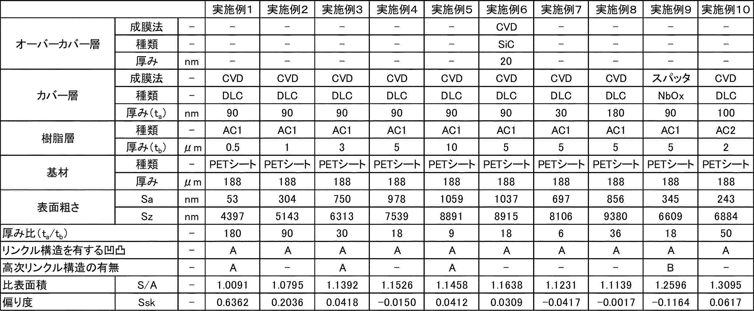

表1、2に示すように、各実施例では、半硬化した樹脂層前駆体にドライプロセスによる表面処理を施すことで、積層体の最表面にリンクル構造を含む凹凸を形成できた。実施例1から実施例5より、樹脂層の厚さを変えることで凹凸段差の制御が容易に実施可能なことがわかる。また、例えば実施例3と実施例9より、ドライプロセス処理の変更で、単純なリンクル構造と複雑なリンクル構造(一次リンクル構造と二次リンクルの一括形成)の作り分けが可能なことがわかる。さらに、実施例12及び実施例17より、容器内面のような立体形状にも適用可能なことがわかる。そのため、表面の微細な凹凸を活用する各種用途(付着防止、光透過性など)に対して、最適な凹凸構造が形成可能となる。
それに対して、各比較例の積層体は、最表面にリンクル構造を含む凹凸を有していなかった。
それに対して、各比較例の積層体は、最表面にリンクル構造を含む凹凸を有していなかった。
<試験例2:実施例18~20及び比較例1、3>
試験例2では、カバー層を無機物含有層とした実施例18~20の積層体について、表面のリンクル構造及び撥水性を確認し、比較例1及び3と比較した。
試験例2では、カバー層を無機物含有層とした実施例18~20の積層体について、表面のリンクル構造及び撥水性を確認し、比較例1及び3と比較した。
実施例18
(樹脂層前駆体の形成)
上記試験例1と同じ熱硬化性樹脂組成物(AC1)の希釈液を、基材としてのPETフィルム(三菱ケミカル株式会社製、製品名「T100タイプ」、厚み188μm)の一方の面上に、硬化後の厚みが表3に記載される通りになるように塗布して、80℃で1分間加熱することで、乾燥かつ硬化して、半硬化の樹脂層前駆体を形成した。その後、室温(23℃)で3時間放置した後、直ちに以下に示すCVD処理を開始した。
(樹脂層前駆体の形成)
上記試験例1と同じ熱硬化性樹脂組成物(AC1)の希釈液を、基材としてのPETフィルム(三菱ケミカル株式会社製、製品名「T100タイプ」、厚み188μm)の一方の面上に、硬化後の厚みが表3に記載される通りになるように塗布して、80℃で1分間加熱することで、乾燥かつ硬化して、半硬化の樹脂層前駆体を形成した。その後、室温(23℃)で3時間放置した後、直ちに以下に示すCVD処理を開始した。
(カバー層の形成)
プラズマCVD装置(株式会社島津製作所製)を使用し、原料ガスとしてヘキサメチルジシロキサン(HMDSO)を60sccm導入して、0.5Paの圧力下にて放電出力500Wの条件下でCVDを行い、半硬化の樹脂層前駆体上に、カバー層として厚み23nmの無機物含有層(SiOxCy層、x=1.2、y=2.0)を形成し、積層体を得た。
プラズマCVD装置(株式会社島津製作所製)を使用し、原料ガスとしてヘキサメチルジシロキサン(HMDSO)を60sccm導入して、0.5Paの圧力下にて放電出力500Wの条件下でCVDを行い、半硬化の樹脂層前駆体上に、カバー層として厚み23nmの無機物含有層(SiOxCy層、x=1.2、y=2.0)を形成し、積層体を得た。
実施例19
厚みが42nmとなるようにカバー層として無機物含有層(SiOxCy層、x=1.2、y=2.0)を形成した以外は、実施例18と同様に実施した。
厚みが42nmとなるようにカバー層として無機物含有層(SiOxCy層、x=1.2、y=2.0)を形成した以外は、実施例18と同様に実施した。
実施例20
(樹脂層前駆体の形成)
基材としてPETボトル(日本メデカルサイエンス社製のPET広口瓶、容量100ml、側壁面厚み800μm)を使用し、PETボトルの側壁面の内面(一方の面)に熱硬化性樹脂組成物(AC1)の希釈液を塗布して、80℃で1分間加熱することで、乾燥かつ硬化して、半硬化の樹脂層前駆体を形成した。その後、室温(23℃)で3時間放置した後、直ちに以下に示すCVD処理を開始した。
(樹脂層前駆体の形成)
基材としてPETボトル(日本メデカルサイエンス社製のPET広口瓶、容量100ml、側壁面厚み800μm)を使用し、PETボトルの側壁面の内面(一方の面)に熱硬化性樹脂組成物(AC1)の希釈液を塗布して、80℃で1分間加熱することで、乾燥かつ硬化して、半硬化の樹脂層前駆体を形成した。その後、室温(23℃)で3時間放置した後、直ちに以下に示すCVD処理を開始した。
(カバー層の形成)
プラズマCVD装置(神港精機(株)社製)を用いて、原料ガスとしてテトラメチルシランを20sccm導入し、さらにアルゴンを50sccm導入して、0.15Paの減圧下にてCVDを行い、半硬化の樹脂層前駆体の上に、カバー層として厚み140nmの炭化ケイ素(SiC)層を形成し、積層体を得た。
プラズマCVD装置(神港精機(株)社製)を用いて、原料ガスとしてテトラメチルシランを20sccm導入し、さらにアルゴンを50sccm導入して、0.15Paの減圧下にてCVDを行い、半硬化の樹脂層前駆体の上に、カバー層として厚み140nmの炭化ケイ素(SiC)層を形成し、積層体を得た。
比較例1、3
上記試験例1と同じ比較例1及び3の積層体を用いた。
上記試験例1と同じ比較例1及び3の積層体を用いた。
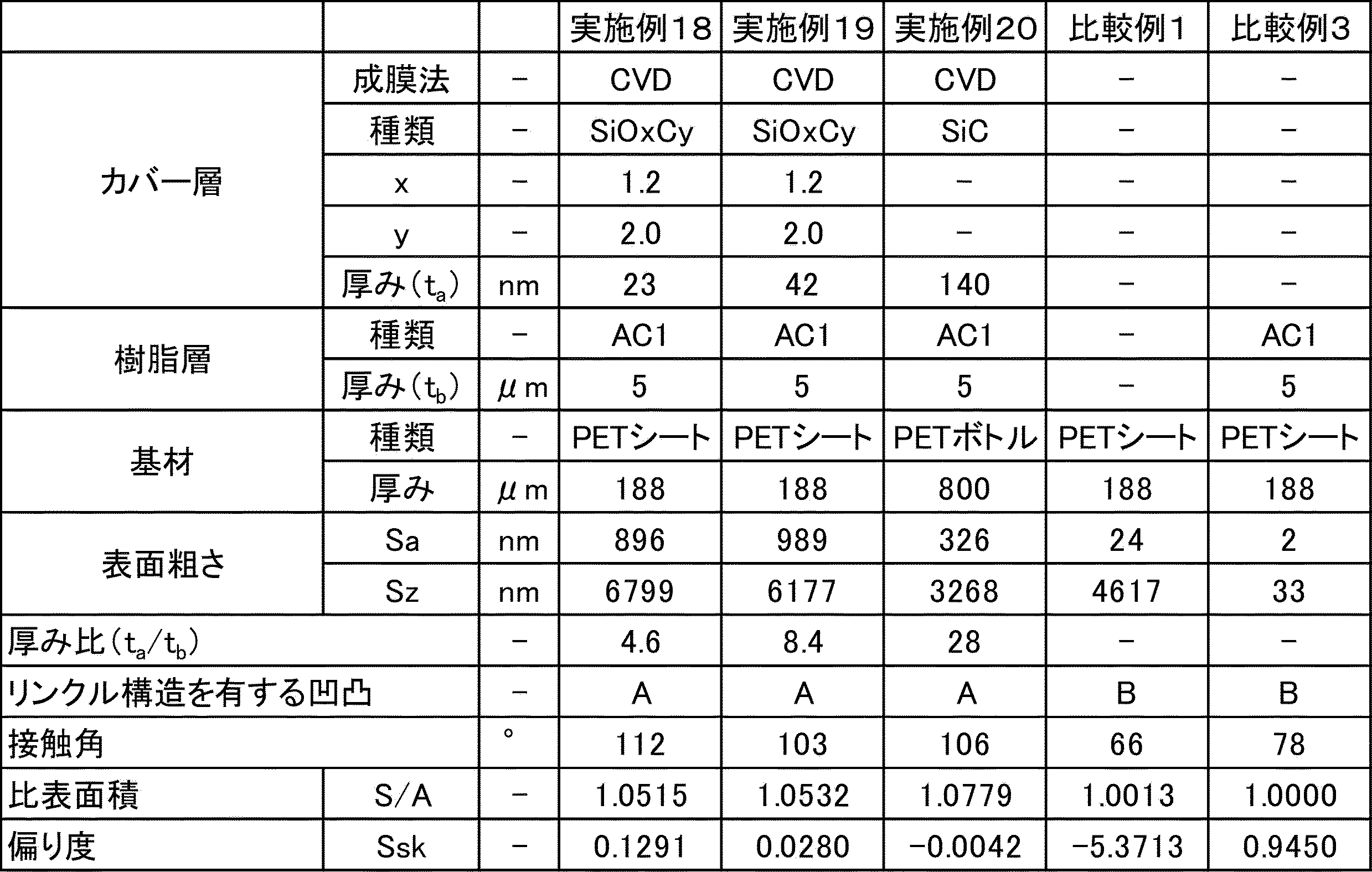
表3に示すように、各実施例では、半硬化した樹脂層前駆体にドライプロセスによりカバー層(無機物含有層)を形成することで、積層体の最表面の表面粗さ(Sa,Sz)及び比表面積をいずれも大きくすることができた。そのため、ケイ素系化合物から形成される無機物含有層が設けられることも相まって、水に対する接触角が大きくなり、良好な撥液性を有していた。
それに対して、比較例では、カバー層(無機物含有層)が形成されず、また積層体の最表面の表面粗さ(Sa,Sz)及び比表面積がいずれも小さいため、水に対する接触角が小さいままであり、良好な撥液性を得られなかった。
それに対して、比較例では、カバー層(無機物含有層)が形成されず、また積層体の最表面の表面粗さ(Sa,Sz)及び比表面積がいずれも小さいため、水に対する接触角が小さいままであり、良好な撥液性を得られなかった。
<試験例3:実施例17、21~24、比較例1、2、4及び参考例1>
試験例3では、カバー層の表面にフッ素系化合物を有する積層体として、実施例17、実施例21~24の積層体の表面のリンクル構造及び撥水性を確認し、比較例1、2、4及び参考例1と比較した。
試験例3では、カバー層の表面にフッ素系化合物を有する積層体として、実施例17、実施例21~24の積層体の表面のリンクル構造及び撥水性を確認し、比較例1、2、4及び参考例1と比較した。
実施例17
上記試験例1と同じ実施例17の積層体を用いた。
上記試験例1と同じ実施例17の積層体を用いた。
実施例21
(樹脂層前駆体の形成)
上記試験例1と同じ熱硬化性樹脂組成物(AC1)の希釈液を、基材としてのPETフィルム(三菱ケミカル株式会社製、製品名「T100タイプ」、厚み188μm)の一方の面上に、積層体における厚みが表4に記載される通りになるように塗布して、80℃で1分間加熱することで、乾燥かつ硬化して、半硬化の樹脂層前駆体を形成した。その後、室温(23℃)で3時間放置した後、直ちに以下に示すCVD処理を開始した。
(樹脂層前駆体の形成)
上記試験例1と同じ熱硬化性樹脂組成物(AC1)の希釈液を、基材としてのPETフィルム(三菱ケミカル株式会社製、製品名「T100タイプ」、厚み188μm)の一方の面上に、積層体における厚みが表4に記載される通りになるように塗布して、80℃で1分間加熱することで、乾燥かつ硬化して、半硬化の樹脂層前駆体を形成した。その後、室温(23℃)で3時間放置した後、直ちに以下に示すCVD処理を開始した。
(カバー層の形成)
プラズマCVD装置(ユーテック株式会社製)を使用して、アセチレンガスを導入して、分圧を1Paとし、1Paの真空下にて電力500WでCVDを行い、半硬化の樹脂層前駆体上に、カバー層として厚み90nmの無機物含有層(DLC層)を形成した。
プラズマCVD装置(ユーテック株式会社製)を使用して、アセチレンガスを導入して、分圧を1Paとし、1Paの真空下にて電力500WでCVDを行い、半硬化の樹脂層前駆体上に、カバー層として厚み90nmの無機物含有層(DLC層)を形成した。
(フッ化処理)
パーフルオロアルキルエーテル基を有するトリメトキシシランであるシランカップリング剤(キャノンオプトロン(株)社製、商品名「SURFCLEAR100」。以下「SC」とも表記する)を使用して、10nmの膜厚で真空蒸着を行い、カバー層の表面をフッ化処理して、カバー層の表面にフッ素系化合物を含有させた。これにより、基材/樹脂層/カバー層の積層構造を有し、かつカバー層の表面がフッ素系化合物を有する積層体を得た。
パーフルオロアルキルエーテル基を有するトリメトキシシランであるシランカップリング剤(キャノンオプトロン(株)社製、商品名「SURFCLEAR100」。以下「SC」とも表記する)を使用して、10nmの膜厚で真空蒸着を行い、カバー層の表面をフッ化処理して、カバー層の表面にフッ素系化合物を含有させた。これにより、基材/樹脂層/カバー層の積層構造を有し、かつカバー層の表面がフッ素系化合物を有する積層体を得た。
実施例22、23
得られた積層体における厚みが表4に記載となるよう樹脂層を形成した以外は、実施例21と同様に実施した。
得られた積層体における厚みが表4に記載となるよう樹脂層を形成した以外は、実施例21と同様に実施した。
実施例24
実施例23と同様に基材の上に樹脂層、及びカバー層を形成した後、以下のフッ化処理を行って、フッ素系化合物層を形成した。これにより、基材/樹脂層/カバー層/フッ素系化合物層の積層構造を有する積層体を得た。
(フッ化処理)
プラズマCVD装置(神港精機(株))を使用して、オクタフルオロプロパン(C3F8)を10sccm導入して、5Paの真空下にてCVDを行い、カバー層の上に厚み10nmのフッ素系化合物層(フッ素系樹脂層)を形成した。
実施例23と同様に基材の上に樹脂層、及びカバー層を形成した後、以下のフッ化処理を行って、フッ素系化合物層を形成した。これにより、基材/樹脂層/カバー層/フッ素系化合物層の積層構造を有する積層体を得た。
(フッ化処理)
プラズマCVD装置(神港精機(株))を使用して、オクタフルオロプロパン(C3F8)を10sccm導入して、5Paの真空下にてCVDを行い、カバー層の上に厚み10nmのフッ素系化合物層(フッ素系樹脂層)を形成した。
比較例1、2
上記試験例1と同じ比較例1、2の積層体を用いた。
上記試験例1と同じ比較例1、2の積層体を用いた。
比較例4
樹脂層前駆体及びカバー層の形成を省略して、基材/フッ素系樹脂層の積層構造を有する積層体を得た点を除いて実施例24と同様に実施した。
樹脂層前駆体及びカバー層の形成を省略して、基材/フッ素系樹脂層の積層構造を有する積層体を得た点を除いて実施例24と同様に実施した。
参考例1
テフロン(登録商標)板(PTFE板、アズワン株式会社製、製品名「3-3282-01」、厚み1000μm)からなる基材単体を参考例1の積層体とした。
テフロン(登録商標)板(PTFE板、アズワン株式会社製、製品名「3-3282-01」、厚み1000μm)からなる基材単体を参考例1の積層体とした。

表4に示すように、各実施例では、樹脂層前駆体上にドライプロセスによりカバー層を形成することで、積層体の最表面にリンクル構造を含む凹凸を形成でき、表面粗さ(Sa,Sz)及び比表面積をいずれも大きくすることができた。そのため、カバー層の表面にフッ素系化合物を含有させることも相まって、水に対する接触角が大きくなり、良好な撥液性を発揮することができた。
それに対して、比較例1、2では、樹脂層が設けられず、又はドライプロセスにより凹凸を形成しなかったため、積層体の最表面にリンクル構造を含む凹凸を形成できず、表面粗さ(Sa,Sz)及び比表面積をいずれも大きくすることができなかった。そのため、水に対する接触角が小さく、良好な撥液性を得られなかった。
比較例4では、積層体の最表面にフッ素系化合物を有するが、リンクル構造を含む凹凸を有しないため、実施例17、21~24に比べて水に対する接触角が小さかった。
さらに、参考例1より、実施例17、21~24の積層体は一般的なテフロン板よりも水に対する接触角が大きいことが確認できた。
それに対して、比較例1、2では、樹脂層が設けられず、又はドライプロセスにより凹凸を形成しなかったため、積層体の最表面にリンクル構造を含む凹凸を形成できず、表面粗さ(Sa,Sz)及び比表面積をいずれも大きくすることができなかった。そのため、水に対する接触角が小さく、良好な撥液性を得られなかった。
比較例4では、積層体の最表面にフッ素系化合物を有するが、リンクル構造を含む凹凸を有しないため、実施例17、21~24に比べて水に対する接触角が小さかった。
さらに、参考例1より、実施例17、21~24の積層体は一般的なテフロン板よりも水に対する接触角が大きいことが確認できた。
<試験例4:実施例25~28及び比較例1、5>
試験例4では、実施例25~28の積層体の表面のリンクル構造及びヘイズを確認し、比較例1、5と比較した。
試験例4では、実施例25~28の積層体の表面のリンクル構造及びヘイズを確認し、比較例1、5と比較した。
実施例25
(樹脂層前駆体の形成)
上記試験例1と同じ活性エネルギー線硬化性樹脂組成物(AC2)の希釈液を、基材としてのPETフィルム(三菱ケミカル株式会社製、製品名「T100タイプ」、厚み188μm)の一方の面上に、乾燥後の厚みが表5に記載される通りになるように塗布して、80℃で1分間加熱することで乾燥させ、その後、紫外線照射装置(ウシオ電機(株)製)を使用して、高圧水銀ランプの紫外線を積算光量427mJ/cm2照射して硬化して、半硬化の樹脂層前駆体を形成した。なお、半硬化の樹脂層前駆体表面のべたつきは微弱であった。その後、室温(23℃)で3時間放置した後に、以下に示す真空蒸着を直ちに開始した。
(樹脂層前駆体の形成)
上記試験例1と同じ活性エネルギー線硬化性樹脂組成物(AC2)の希釈液を、基材としてのPETフィルム(三菱ケミカル株式会社製、製品名「T100タイプ」、厚み188μm)の一方の面上に、乾燥後の厚みが表5に記載される通りになるように塗布して、80℃で1分間加熱することで乾燥させ、その後、紫外線照射装置(ウシオ電機(株)製)を使用して、高圧水銀ランプの紫外線を積算光量427mJ/cm2照射して硬化して、半硬化の樹脂層前駆体を形成した。なお、半硬化の樹脂層前駆体表面のべたつきは微弱であった。その後、室温(23℃)で3時間放置した後に、以下に示す真空蒸着を直ちに開始した。
(カバー層の形成)
真空蒸着装置((株)アルバック製)を使用して、酸化ケイ素を蒸着源として、真空蒸着を行い、半硬化の樹脂層前駆体上に厚み50nmの無機物含有層(1)(酸化ケイ素(SiOx)層)を形成し、基材/樹脂層/カバー層の積層構造を有する積層体を得た。
真空蒸着装置((株)アルバック製)を使用して、酸化ケイ素を蒸着源として、真空蒸着を行い、半硬化の樹脂層前駆体上に厚み50nmの無機物含有層(1)(酸化ケイ素(SiOx)層)を形成し、基材/樹脂層/カバー層の積層構造を有する積層体を得た。
実施例26
カバー層の形成を以下の方法で実施して、カバー層をDLC層とした以外は、実施例1と同様に実施した。
(カバー層の形成)
プラズマCVD装置(ユーテック株式会社製)を使用して、アセチレンガスを導入して、分圧を1Paとし、1Paの真空下にて電力500WでCVDを行い、半硬化の樹脂層前駆体上に厚み100nmの無機物含有層(1)(DLC層)を形成し、基材/樹脂層/カバー層の積層構造を有する積層体を得た。
カバー層の形成を以下の方法で実施して、カバー層をDLC層とした以外は、実施例1と同様に実施した。
(カバー層の形成)
プラズマCVD装置(ユーテック株式会社製)を使用して、アセチレンガスを導入して、分圧を1Paとし、1Paの真空下にて電力500WでCVDを行い、半硬化の樹脂層前駆体上に厚み100nmの無機物含有層(1)(DLC層)を形成し、基材/樹脂層/カバー層の積層構造を有する積層体を得た。
実施例27、28
(活性エネルギー線硬化性樹脂組成物(AC3)の調製)
光重合性化合物としてのフルオレン系2官能アクリレート(大阪ガスケミカル社製、製品名「オグソールEA-0250P」)を、溶剤であるメチルイソブチルケトン(MIBK)に固形分濃度が10質量%となるように添加し溶解させて、活性エネルギー線硬化性樹脂組成物(AC3)の希釈液を得た。
(活性エネルギー線硬化性樹脂組成物(AC3)の調製)
光重合性化合物としてのフルオレン系2官能アクリレート(大阪ガスケミカル社製、製品名「オグソールEA-0250P」)を、溶剤であるメチルイソブチルケトン(MIBK)に固形分濃度が10質量%となるように添加し溶解させて、活性エネルギー線硬化性樹脂組成物(AC3)の希釈液を得た。
活性エネルギー線硬化性樹脂組成物(A3)を用いた点を除いて、実施例25、26と同様に実施した。なお、半硬化の樹脂層前駆体の表面は多少のべたつきがあった。
比較例1
試験例1と同じ比較例1の積層体を用いた。
試験例1と同じ比較例1の積層体を用いた。
比較例5
樹脂層前駆体の形成を省略して、基材/カバー層の積層構造を有する積層体を得た点を除いて実施例25と同様に実施した。
樹脂層前駆体の形成を省略して、基材/カバー層の積層構造を有する積層体を得た点を除いて実施例25と同様に実施した。
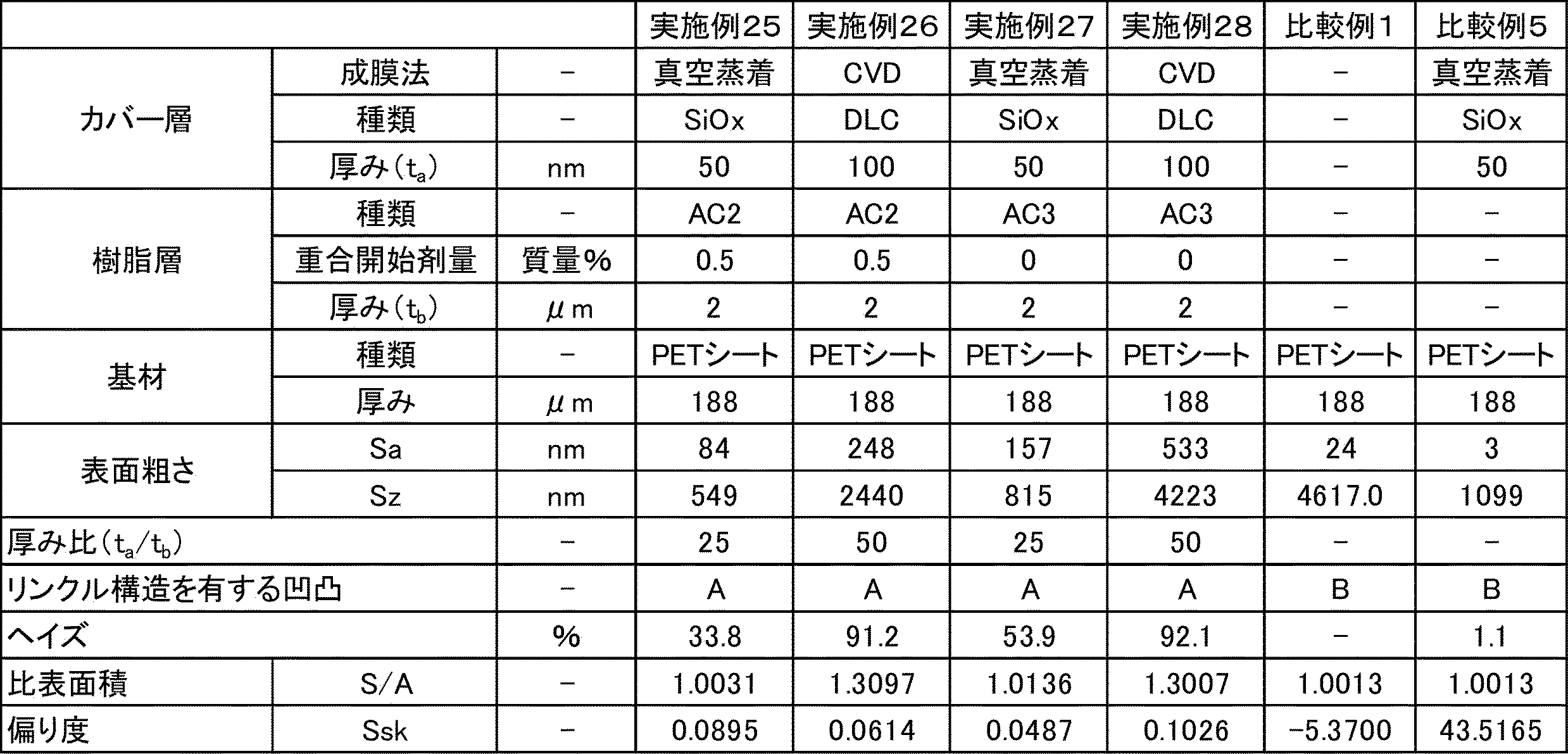
表5に示すように、各実施例では、活性エネルギー線硬化性樹脂組成物により形成した樹脂層前駆体に、活性エネルギー線を照射し、その後、ドライプロセスによる表面処理を施すことで、積層体の最表面にリンクル構造を含む凹凸を形成できた。
一方で、比較例1、5では、樹脂層を形成せずに、又は樹脂層に対してドライプロセスによる表面処理を施さなかったため、積層体の最表面にリンクル構造を含む凹凸が形成されなかった。
加えて、実施例25~28の対比から明らかなように、活性エネルギー線重合開始剤の配合の有無、及び、ドライプロセスの違いによって、凹凸の大きさの制御ができ、表面の微細な凹凸を活用する各種用途(付着防止、光透過性など)に適した凹凸構造を形成できる。なお、実施例25、26では、活性エネルギー線重合開始剤を微量含むことで、エネルギー線照射後の樹脂層前駆体は、表面のべたつきが微弱となり、ハンドリング性にも優れていた。
一方で、比較例1、5では、樹脂層を形成せずに、又は樹脂層に対してドライプロセスによる表面処理を施さなかったため、積層体の最表面にリンクル構造を含む凹凸が形成されなかった。
加えて、実施例25~28の対比から明らかなように、活性エネルギー線重合開始剤の配合の有無、及び、ドライプロセスの違いによって、凹凸の大きさの制御ができ、表面の微細な凹凸を活用する各種用途(付着防止、光透過性など)に適した凹凸構造を形成できる。なお、実施例25、26では、活性エネルギー線重合開始剤を微量含むことで、エネルギー線照射後の樹脂層前駆体は、表面のべたつきが微弱となり、ハンドリング性にも優れていた。
<試験例5:実施例29~36>
試験例5では、実施例29~36の積層体の表面のリンクル構造を観察した。
試験例5では、実施例29~36の積層体の表面のリンクル構造を観察した。
実施例29
(熱硬化性樹脂組成物(AC4)の調製)
バインダー樹脂としてのアクリルポリオール(株式会社日本触媒製、製品名「UV-G301」、固形分42.4%の酢酸エチル溶液)の固形分2.12質量部と、硬化剤としてのイソシアネート系化合物(三井化学株式会社製、製品名「タケネートD-165N」、ヘキサメチレンジイソシアネート系化合物、固形分100%)0.06質量部に対して、溶剤としての酢酸エチルを固形分濃度21.83質量%になるように添加して混合し、熱硬化性樹脂組成物(AC4)の希釈液を用意した。
(熱硬化性樹脂組成物(AC4)の調製)
バインダー樹脂としてのアクリルポリオール(株式会社日本触媒製、製品名「UV-G301」、固形分42.4%の酢酸エチル溶液)の固形分2.12質量部と、硬化剤としてのイソシアネート系化合物(三井化学株式会社製、製品名「タケネートD-165N」、ヘキサメチレンジイソシアネート系化合物、固形分100%)0.06質量部に対して、溶剤としての酢酸エチルを固形分濃度21.83質量%になるように添加して混合し、熱硬化性樹脂組成物(AC4)の希釈液を用意した。
(樹脂層前駆体の形成)
得られた熱硬化性樹脂組成物(AC4)の希釈液を、基材としてのPETフィルム(三菱ケミカル株式会社製、製品名「T100タイプ」、厚み188μm)の一方の面上に、硬化後の厚みが表6に記載される通りになるように塗布して、80℃で1分間加熱することで、乾燥かつ硬化して、半硬化の樹脂層前駆体を形成した。その後、室温(23℃)で3時間放置した後、直ちに以下に示すCVD処理を開始した。
得られた熱硬化性樹脂組成物(AC4)の希釈液を、基材としてのPETフィルム(三菱ケミカル株式会社製、製品名「T100タイプ」、厚み188μm)の一方の面上に、硬化後の厚みが表6に記載される通りになるように塗布して、80℃で1分間加熱することで、乾燥かつ硬化して、半硬化の樹脂層前駆体を形成した。その後、室温(23℃)で3時間放置した後、直ちに以下に示すCVD処理を開始した。
(カバー層の形成)
プラズマCVD装置(ユーテック株式会社製)を使用して、アセチレンガスを導入して、分圧を1Paとし、1Paの真空下にて電力500WでCVDを行い、半硬化の樹脂層前駆体上に厚み90nmの無機物含有層(1)(DLC層)を形成し、基材/樹脂層/カバー層の積層構造を有する積層体を得た。
プラズマCVD装置(ユーテック株式会社製)を使用して、アセチレンガスを導入して、分圧を1Paとし、1Paの真空下にて電力500WでCVDを行い、半硬化の樹脂層前駆体上に厚み90nmの無機物含有層(1)(DLC層)を形成し、基材/樹脂層/カバー層の積層構造を有する積層体を得た。
実施例30~36
熱硬化性樹脂組成物の配合を表6に記載の通りに変更した以外は、実施例29と同様に実施した。
熱硬化性樹脂組成物の配合を表6に記載の通りに変更した以外は、実施例29と同様に実施した。

表6に示すように、実施例29~31の積層体は一次リンクル構造のみであったのに対し、実施例32~36の積層体は一次リンクル構造と、一次リンクル構造よりもうねりの周期が小さい二次リンクル構造を含む凹凸(階層的凹凸構造)を有していた。実施例29~36より、樹脂層におけるバインダー樹脂と硬化剤の配合比を調節することで、凹凸の制御が容易に実施可能なことがわかる。
10 積層体
10A 積層体の最表面
11 基材
11A 基材の一方の面
12 樹脂層
13 カバー層
14 オーバーカバー層
10A 積層体の最表面
11 基材
11A 基材の一方の面
12 樹脂層
13 カバー層
14 オーバーカバー層
Claims (15)
- 基材と、前記基材の少なくとも一方の面に設けられる樹脂層とを備える積層体であって、
前記樹脂層が、熱又は活性エネルギー線硬化性樹脂組成物から形成され、
前記基材の前記一方の面側における前記積層体の最表面が、リンクル構造を含む凹凸を有する積層体。 - 前記樹脂層が座屈してリンクル構造を形成している、請求項1に記載の積層体。
- 前記最表面の比表面積(S/A)が、1.005以上である請求項1又は2に記載の積層体。
- 前記最表面のSa(算術平均粗さ)が50nm以上である、請求項1~3のいずれか1項に記載の積層体。
- 前記最表面のSz(最大高さ)が4000nm以上である、請求項1~4のいずれか1項に記載の積層体。
- 前記最表面のSsk(偏り度)の絶対値が5以下である、請求項1~5のいずれか1項に記載の積層体。
- 前記樹脂層上にさらにカバー層を備える請求項1~6のいずれか1項に記載の積層体。
- 前記カバー層が、無機物含有層及びカバー樹脂層のいずれかである請求項1~7のいずれか1項に記載の積層体。
- 前記無機物含有層が、ダイヤモンドライクカーボン、金属、金属酸化物、金属窒化物、金属炭化物、及びこれらの複合物からなる群から選ばれる少なくとも一種から形成される請求項8に記載の積層体。
- 前記無機物含有層がケイ素系化合物から形成される、請求項8又は9に記載の積層体。
- 前記カバー層が、少なくとも表面にフッ素系化合物を含有する、請求項7~10のいずれか1項に記載の積層体。
- 前記リンクル構造が一次リンクル構造と、前記一次リンクル構造よりもうねりの周期が小さい二次リンクル構造とを含む、請求項1~11のいずれか1項に記載の積層体。
- 基材の少なくとも一方の面に熱又は活性エネルギー線硬化性樹脂組成物を塗布して樹脂層前駆体を形成する工程と、
半硬化又は未硬化の前記樹脂層前駆体に対してさらにドライプロセスによる表面処理を行い、前記基材の一方の面側の表面においてリンクル構造を含む凹凸を形成する工程と
を備える積層体の製造方法。 - 前記表面処理が、化学的気相蒸着、物理的気相蒸着、及びプラズマ処理のいずれかである請求項13に記載の積層体の製造方法。
- 前記塗布により形成した樹脂層前駆体を半硬化させる工程を備え、
前記表面処理を前記半硬化させた樹脂層前駆体に対して行う請求項13又は14に記載の積層体の製造方法。
Priority Applications (4)
| Application Number | Priority Date | Filing Date | Title |
|---|---|---|---|
| EP21756541.5A EP4108445A4 (en) | 2020-02-17 | 2021-02-16 | LAMINATE AND METHOD FOR MANUFACTURING LAMINATE |
| CN202180014449.1A CN115151410A (zh) | 2020-02-17 | 2021-02-16 | 层叠体和层叠体的制造方法 |
| KR1020227028120A KR20220143033A (ko) | 2020-02-17 | 2021-02-16 | 적층체, 및 적층체의 제조 방법 |
| US17/887,943 US20220389240A1 (en) | 2020-02-17 | 2022-08-15 | Laminate and method for manufacturing laminate |
Applications Claiming Priority (18)
| Application Number | Priority Date | Filing Date | Title |
|---|---|---|---|
| JP2020024719 | 2020-02-17 | ||
| JP2020-024719 | 2020-02-17 | ||
| JP2020-029713 | 2020-02-25 | ||
| JP2020029713 | 2020-02-25 | ||
| JP2020-052995 | 2020-03-24 | ||
| JP2020052995 | 2020-03-24 | ||
| JP2020057970A JP7661676B2 (ja) | 2020-03-27 | 2020-03-27 | 積層体、及び積層体の製造方法 |
| JP2020-057970 | 2020-03-27 | ||
| JP2020098000 | 2020-06-04 | ||
| JP2020-098000 | 2020-06-04 | ||
| JP2020189447A JP2021133682A (ja) | 2020-02-25 | 2020-11-13 | 積層体、及び積層体の製造方法 |
| JP2020-189433 | 2020-11-13 | ||
| JP2020-189432 | 2020-11-13 | ||
| JP2020189433A JP2021151768A (ja) | 2020-03-24 | 2020-11-13 | 積層体、及び積層体の製造方法 |
| JP2020189432A JP2021126898A (ja) | 2020-02-17 | 2020-11-13 | 積層体、及び積層体の製造方法 |
| JP2020-189447 | 2020-11-13 | ||
| JP2020-189442 | 2020-11-13 | ||
| JP2020189442A JP2021191624A (ja) | 2020-06-04 | 2020-11-13 | 積層体、及び積層体の製造方法 |
Related Child Applications (1)
| Application Number | Title | Priority Date | Filing Date |
|---|---|---|---|
| US17/887,943 Continuation US20220389240A1 (en) | 2020-02-17 | 2022-08-15 | Laminate and method for manufacturing laminate |
Publications (1)
| Publication Number | Publication Date |
|---|---|
| WO2021166911A1 true WO2021166911A1 (ja) | 2021-08-26 |
Family
ID=77391881
Family Applications (1)
| Application Number | Title | Priority Date | Filing Date |
|---|---|---|---|
| PCT/JP2021/005714 Ceased WO2021166911A1 (ja) | 2020-02-17 | 2021-02-16 | 積層体、及び積層体の製造方法 |
Country Status (5)
| Country | Link |
|---|---|
| US (1) | US20220389240A1 (ja) |
| EP (1) | EP4108445A4 (ja) |
| KR (1) | KR20220143033A (ja) |
| CN (1) | CN115151410A (ja) |
| WO (1) | WO2021166911A1 (ja) |
Cited By (2)
| Publication number | Priority date | Publication date | Assignee | Title |
|---|---|---|---|---|
| WO2025075203A1 (ja) * | 2023-10-06 | 2025-04-10 | Agc株式会社 | 物品、及び物品の製造方法 |
| WO2025115759A1 (ja) * | 2023-11-29 | 2025-06-05 | Toppanホールディングス株式会社 | 化粧シート及びその製造方法 |
Families Citing this family (3)
| Publication number | Priority date | Publication date | Assignee | Title |
|---|---|---|---|---|
| CA3176601A1 (en) | 2020-03-25 | 2021-09-30 | Flexcon Company, Inc. | Isotropic non-aqueous electrode sensing material |
| US12474507B2 (en) * | 2021-07-15 | 2025-11-18 | Samsung Electro-Mechanics Co., Ltd. | Lens, lens assembly, and mobile electronic device |
| KR102662848B1 (ko) * | 2022-05-02 | 2024-05-03 | 삼성전기주식회사 | 렌즈, 렌즈 어셈블리 및 휴대용 전자기기 |
Citations (8)
| Publication number | Priority date | Publication date | Assignee | Title |
|---|---|---|---|---|
| JPS4933588B1 (ja) * | 1968-08-14 | 1974-09-07 | ||
| JPH0953024A (ja) * | 1995-08-10 | 1997-02-25 | Dainippon Ink & Chem Inc | 艶消し表面形成用樹脂組成物及び艶消し表面の形成方法 |
| JP2000284302A (ja) * | 1999-04-01 | 2000-10-13 | Toppan Printing Co Ltd | 反射型液晶表示装置用電極基板及びその製造方法 |
| JP2011140190A (ja) * | 2010-01-08 | 2011-07-21 | Mitsubishi Rayon Co Ltd | フィルムおよびフィルムの製造方法 |
| WO2012043828A1 (ja) * | 2010-09-30 | 2012-04-05 | 三菱レイヨン株式会社 | 微細凹凸構造を表面に有するモールド、微細凹凸構造を表面に有する物品の製造方法、物品の用途、虹彩色を発現する積層体および面発光体 |
| JP2014008470A (ja) * | 2012-06-29 | 2014-01-20 | Fujitsu Ltd | ラメ模様の加飾方法及びラメ模様の加飾構造 |
| JP2018157180A (ja) * | 2017-03-17 | 2018-10-04 | スタンレー電気株式会社 | 樹脂成形体及び発光装置の製造方法並びに発光装置 |
| JP2021024179A (ja) * | 2019-08-02 | 2021-02-22 | 三菱ケミカル株式会社 | 積層体 |
Family Cites Families (7)
| Publication number | Priority date | Publication date | Assignee | Title |
|---|---|---|---|---|
| WO2010073781A1 (ja) * | 2008-12-26 | 2010-07-01 | 帝人株式会社 | 透明導電性積層体及びそれを用いた透明タッチパネル |
| JPWO2014192709A1 (ja) * | 2013-05-27 | 2017-02-23 | 三菱レイヨン株式会社 | 積層体及びその製造方法 |
| WO2015027371A1 (en) * | 2013-08-26 | 2015-03-05 | Logitech Europe S.A. | Touch surface for an electronic device and method for manufacturing the same |
| JP2015074137A (ja) * | 2013-10-08 | 2015-04-20 | デクセリアルズ株式会社 | 親油性積層体、及びその製造方法、並びに物品 |
| JP6349683B2 (ja) * | 2013-11-11 | 2018-07-04 | Dic株式会社 | 積層体 |
| JP6761594B2 (ja) | 2016-06-24 | 2020-09-30 | 大日本印刷株式会社 | 撥水性積層体および撥水性積層体の製造方法 |
| TWI842673B (zh) * | 2017-06-05 | 2024-05-21 | 日商日本化工塗料股份有限公司 | 用以在環狀烯烴系樹脂基材上形成硬化被膜之活性能量線硬化型組成物、以及以環狀烯烴系樹脂為基材之硬塗薄膜及積層體 |
-
2021
- 2021-02-16 EP EP21756541.5A patent/EP4108445A4/en not_active Withdrawn
- 2021-02-16 WO PCT/JP2021/005714 patent/WO2021166911A1/ja not_active Ceased
- 2021-02-16 CN CN202180014449.1A patent/CN115151410A/zh active Pending
- 2021-02-16 KR KR1020227028120A patent/KR20220143033A/ko not_active Withdrawn
-
2022
- 2022-08-15 US US17/887,943 patent/US20220389240A1/en not_active Abandoned
Patent Citations (8)
| Publication number | Priority date | Publication date | Assignee | Title |
|---|---|---|---|---|
| JPS4933588B1 (ja) * | 1968-08-14 | 1974-09-07 | ||
| JPH0953024A (ja) * | 1995-08-10 | 1997-02-25 | Dainippon Ink & Chem Inc | 艶消し表面形成用樹脂組成物及び艶消し表面の形成方法 |
| JP2000284302A (ja) * | 1999-04-01 | 2000-10-13 | Toppan Printing Co Ltd | 反射型液晶表示装置用電極基板及びその製造方法 |
| JP2011140190A (ja) * | 2010-01-08 | 2011-07-21 | Mitsubishi Rayon Co Ltd | フィルムおよびフィルムの製造方法 |
| WO2012043828A1 (ja) * | 2010-09-30 | 2012-04-05 | 三菱レイヨン株式会社 | 微細凹凸構造を表面に有するモールド、微細凹凸構造を表面に有する物品の製造方法、物品の用途、虹彩色を発現する積層体および面発光体 |
| JP2014008470A (ja) * | 2012-06-29 | 2014-01-20 | Fujitsu Ltd | ラメ模様の加飾方法及びラメ模様の加飾構造 |
| JP2018157180A (ja) * | 2017-03-17 | 2018-10-04 | スタンレー電気株式会社 | 樹脂成形体及び発光装置の製造方法並びに発光装置 |
| JP2021024179A (ja) * | 2019-08-02 | 2021-02-22 | 三菱ケミカル株式会社 | 積層体 |
Non-Patent Citations (1)
| Title |
|---|
| See also references of EP4108445A4 * |
Cited By (2)
| Publication number | Priority date | Publication date | Assignee | Title |
|---|---|---|---|---|
| WO2025075203A1 (ja) * | 2023-10-06 | 2025-04-10 | Agc株式会社 | 物品、及び物品の製造方法 |
| WO2025115759A1 (ja) * | 2023-11-29 | 2025-06-05 | Toppanホールディングス株式会社 | 化粧シート及びその製造方法 |
Also Published As
| Publication number | Publication date |
|---|---|
| CN115151410A (zh) | 2022-10-04 |
| KR20220143033A (ko) | 2022-10-24 |
| US20220389240A1 (en) | 2022-12-08 |
| EP4108445A1 (en) | 2022-12-28 |
| EP4108445A4 (en) | 2024-03-20 |
Similar Documents
| Publication | Publication Date | Title |
|---|---|---|
| WO2021166911A1 (ja) | 積層体、及び積層体の製造方法 | |
| JP6416964B2 (ja) | ハードコート | |
| JP6258012B2 (ja) | ハードコートフィルム、透明導電性フィルムおよび静電容量タッチパネル | |
| WO2006064884A1 (ja) | 活性エネルギー線硬化性樹脂組成物およびその用途 | |
| JP2009013384A (ja) | 易滑性アンチブロッキング光硬化性樹脂組成物、それを基材上に被覆硬化したアンチブロッキング性構造体およびその製法 | |
| JP2014151496A (ja) | 透明積層フィルム及び透明基板 | |
| JP2016155241A (ja) | ガスバリアフィルム積層体とそれを用いた電子部品 | |
| JP6085186B2 (ja) | 透明積層フィルム及び透明基板 | |
| CN107466306A (zh) | 形成双重固化纳米结构转印膜的方法 | |
| US12179189B2 (en) | Film for microfluidic device, microfluidic device and method for manufacturing same | |
| JP2009125965A (ja) | ガスバリアフィルム | |
| JP7651847B2 (ja) | 積層体、及び積層体の製造方法 | |
| JP7661676B2 (ja) | 積層体、及び積層体の製造方法 | |
| JP7782148B2 (ja) | 積層体の製造方法 | |
| KR20180063161A (ko) | 다층 배리어 스택 | |
| JP2021126898A (ja) | 積層体、及び積層体の製造方法 | |
| JP2021151768A (ja) | 積層体、及び積層体の製造方法 | |
| JP2006212987A (ja) | 転写材 | |
| WO2015190572A1 (ja) | ガスバリアフィルム積層体とそれを用いた電子部品 | |
| JP2021133682A (ja) | 積層体、及び積層体の製造方法 | |
| JP2021191624A (ja) | 積層体、及び積層体の製造方法 | |
| JP2019131664A (ja) | 活性エネルギー線硬化性樹脂組成物およびその用途 | |
| JP6307909B2 (ja) | ガスバリア性積層フィルム及び透明基板 | |
| JP2010058476A (ja) | ハードコート層付積層体 | |
| JP6179211B2 (ja) | 透明基板用積層フィルム及びこれを用いたディスプレイパネル |
Legal Events
| Date | Code | Title | Description |
|---|---|---|---|
| 121 | Ep: the epo has been informed by wipo that ep was designated in this application |
Ref document number: 21756541 Country of ref document: EP Kind code of ref document: A1 |
|
| NENP | Non-entry into the national phase |
Ref country code: DE |
|
| ENP | Entry into the national phase |
Ref document number: 2021756541 Country of ref document: EP Effective date: 20220919 |