WO2021171340A1 - 回転式圧縮機および冷凍サイクル装置 - Google Patents
回転式圧縮機および冷凍サイクル装置 Download PDFInfo
- Publication number
- WO2021171340A1 WO2021171340A1 PCT/JP2020/007348 JP2020007348W WO2021171340A1 WO 2021171340 A1 WO2021171340 A1 WO 2021171340A1 JP 2020007348 W JP2020007348 W JP 2020007348W WO 2021171340 A1 WO2021171340 A1 WO 2021171340A1
- Authority
- WO
- WIPO (PCT)
- Prior art keywords
- eccentric
- shaft
- balancer
- compression mechanism
- rotary compressor
- Prior art date
- Legal status (The legal status is an assumption and is not a legal conclusion. Google has not performed a legal analysis and makes no representation as to the accuracy of the status listed.)
- Ceased
Links
Images


Classifications
-
- F—MECHANICAL ENGINEERING; LIGHTING; HEATING; WEAPONS; BLASTING
- F04—POSITIVE - DISPLACEMENT MACHINES FOR LIQUIDS; PUMPS FOR LIQUIDS OR ELASTIC FLUIDS
- F04C—ROTARY-PISTON, OR OSCILLATING-PISTON, POSITIVE-DISPLACEMENT MACHINES FOR LIQUIDS; ROTARY-PISTON, OR OSCILLATING-PISTON, POSITIVE-DISPLACEMENT PUMPS
- F04C23/00—Combinations of two or more pumps, each being of rotary-piston or oscillating-piston type, specially adapted for elastic fluids; Pumping installations specially adapted for elastic fluids; Multi-stage pumps specially adapted for elastic fluids
- F04C23/001—Combinations of two or more pumps, each being of rotary-piston or oscillating-piston type, specially adapted for elastic fluids; Pumping installations specially adapted for elastic fluids; Multi-stage pumps specially adapted for elastic fluids of similar working principle
-
- F—MECHANICAL ENGINEERING; LIGHTING; HEATING; WEAPONS; BLASTING
- F25—REFRIGERATION OR COOLING; COMBINED HEATING AND REFRIGERATION SYSTEMS; HEAT PUMP SYSTEMS; MANUFACTURE OR STORAGE OF ICE; LIQUEFACTION SOLIDIFICATION OF GASES
- F25B—REFRIGERATION MACHINES, PLANTS OR SYSTEMS; COMBINED HEATING AND REFRIGERATION SYSTEMS; HEAT PUMP SYSTEMS
- F25B31/00—Compressor arrangements
- F25B31/02—Compressor arrangements of motor-compressor units
- F25B31/026—Compressor arrangements of motor-compressor units with compressor of rotary type
-
- F—MECHANICAL ENGINEERING; LIGHTING; HEATING; WEAPONS; BLASTING
- F04—POSITIVE - DISPLACEMENT MACHINES FOR LIQUIDS; PUMPS FOR LIQUIDS OR ELASTIC FLUIDS
- F04C—ROTARY-PISTON, OR OSCILLATING-PISTON, POSITIVE-DISPLACEMENT MACHINES FOR LIQUIDS; ROTARY-PISTON, OR OSCILLATING-PISTON, POSITIVE-DISPLACEMENT PUMPS
- F04C18/00—Rotary-piston pumps specially adapted for elastic fluids
- F04C18/30—Rotary-piston pumps specially adapted for elastic fluids having the characteristics covered by two or more of groups F04C18/02, F04C18/08, F04C18/22, F04C18/24, F04C18/48, or having the characteristics covered by one of these groups together with some other type of movement between co-operating members
- F04C18/34—Rotary-piston pumps specially adapted for elastic fluids having the characteristics covered by two or more of groups F04C18/02, F04C18/08, F04C18/22, F04C18/24, F04C18/48, or having the characteristics covered by one of these groups together with some other type of movement between co-operating members having the movement defined in group F04C18/08 or F04C18/22 and relative reciprocation between the co-operating members
- F04C18/356—Rotary-piston pumps specially adapted for elastic fluids having the characteristics covered by two or more of groups F04C18/02, F04C18/08, F04C18/22, F04C18/24, F04C18/48, or having the characteristics covered by one of these groups together with some other type of movement between co-operating members having the movement defined in group F04C18/08 or F04C18/22 and relative reciprocation between the co-operating members with vanes reciprocating with respect to the outer member
- F04C18/3562—Rotary-piston pumps specially adapted for elastic fluids having the characteristics covered by two or more of groups F04C18/02, F04C18/08, F04C18/22, F04C18/24, F04C18/48, or having the characteristics covered by one of these groups together with some other type of movement between co-operating members having the movement defined in group F04C18/08 or F04C18/22 and relative reciprocation between the co-operating members with vanes reciprocating with respect to the outer member the inner and outer member being in contact along one line or continuous surfaces substantially parallel to the axis of rotation
- F04C18/3564—Rotary-piston pumps specially adapted for elastic fluids having the characteristics covered by two or more of groups F04C18/02, F04C18/08, F04C18/22, F04C18/24, F04C18/48, or having the characteristics covered by one of these groups together with some other type of movement between co-operating members having the movement defined in group F04C18/08 or F04C18/22 and relative reciprocation between the co-operating members with vanes reciprocating with respect to the outer member the inner and outer member being in contact along one line or continuous surfaces substantially parallel to the axis of rotation the surfaces of the inner and outer member, forming the working space, being surfaces of revolution
-
- F—MECHANICAL ENGINEERING; LIGHTING; HEATING; WEAPONS; BLASTING
- F04—POSITIVE - DISPLACEMENT MACHINES FOR LIQUIDS; PUMPS FOR LIQUIDS OR ELASTIC FLUIDS
- F04C—ROTARY-PISTON, OR OSCILLATING-PISTON, POSITIVE-DISPLACEMENT MACHINES FOR LIQUIDS; ROTARY-PISTON, OR OSCILLATING-PISTON, POSITIVE-DISPLACEMENT PUMPS
- F04C23/00—Combinations of two or more pumps, each being of rotary-piston or oscillating-piston type, specially adapted for elastic fluids; Pumping installations specially adapted for elastic fluids; Multi-stage pumps specially adapted for elastic fluids
- F04C23/008—Hermetic pumps
-
- F—MECHANICAL ENGINEERING; LIGHTING; HEATING; WEAPONS; BLASTING
- F04—POSITIVE - DISPLACEMENT MACHINES FOR LIQUIDS; PUMPS FOR LIQUIDS OR ELASTIC FLUIDS
- F04C—ROTARY-PISTON, OR OSCILLATING-PISTON, POSITIVE-DISPLACEMENT MACHINES FOR LIQUIDS; ROTARY-PISTON, OR OSCILLATING-PISTON, POSITIVE-DISPLACEMENT PUMPS
- F04C29/00—Component parts, details or accessories of pumps or pumping installations, not provided for in groups F04C18/00 - F04C28/00
- F04C29/0042—Driving elements, brakes, couplings, transmissions specially adapted for pumps
- F04C29/005—Means for transmitting movement from the prime mover to driven parts of the pump, e.g. clutches, couplings, transmissions
- F04C29/0057—Means for transmitting movement from the prime mover to driven parts of the pump, e.g. clutches, couplings, transmissions for eccentric movement
-
- F—MECHANICAL ENGINEERING; LIGHTING; HEATING; WEAPONS; BLASTING
- F04—POSITIVE - DISPLACEMENT MACHINES FOR LIQUIDS; PUMPS FOR LIQUIDS OR ELASTIC FLUIDS
- F04C—ROTARY-PISTON, OR OSCILLATING-PISTON, POSITIVE-DISPLACEMENT MACHINES FOR LIQUIDS; ROTARY-PISTON, OR OSCILLATING-PISTON, POSITIVE-DISPLACEMENT PUMPS
- F04C2230/00—Manufacture
- F04C2230/60—Assembly methods
- F04C2230/605—Balancing
-
- F—MECHANICAL ENGINEERING; LIGHTING; HEATING; WEAPONS; BLASTING
- F04—POSITIVE - DISPLACEMENT MACHINES FOR LIQUIDS; PUMPS FOR LIQUIDS OR ELASTIC FLUIDS
- F04C—ROTARY-PISTON, OR OSCILLATING-PISTON, POSITIVE-DISPLACEMENT MACHINES FOR LIQUIDS; ROTARY-PISTON, OR OSCILLATING-PISTON, POSITIVE-DISPLACEMENT PUMPS
- F04C2240/00—Components
- F04C2240/60—Shafts
-
- F—MECHANICAL ENGINEERING; LIGHTING; HEATING; WEAPONS; BLASTING
- F04—POSITIVE - DISPLACEMENT MACHINES FOR LIQUIDS; PUMPS FOR LIQUIDS OR ELASTIC FLUIDS
- F04C—ROTARY-PISTON, OR OSCILLATING-PISTON, POSITIVE-DISPLACEMENT MACHINES FOR LIQUIDS; ROTARY-PISTON, OR OSCILLATING-PISTON, POSITIVE-DISPLACEMENT PUMPS
- F04C2240/00—Components
- F04C2240/80—Other components
- F04C2240/807—Balance weight, counterweight
-
- F—MECHANICAL ENGINEERING; LIGHTING; HEATING; WEAPONS; BLASTING
- F04—POSITIVE - DISPLACEMENT MACHINES FOR LIQUIDS; PUMPS FOR LIQUIDS OR ELASTIC FLUIDS
- F04C—ROTARY-PISTON, OR OSCILLATING-PISTON, POSITIVE-DISPLACEMENT MACHINES FOR LIQUIDS; ROTARY-PISTON, OR OSCILLATING-PISTON, POSITIVE-DISPLACEMENT PUMPS
- F04C2270/00—Control; Monitoring or safety arrangements
- F04C2270/12—Vibration
Definitions
- An embodiment of the present invention relates to a rotary compressor and a refrigeration cycle device.
- a multi-cylinder rotary compressor with high compression performance In the refrigeration cycle equipment, a multi-cylinder rotary compressor with high compression performance is used.
- the multi-cylinder rotary compressor includes a plurality of compression mechanism portions, a shaft, and a plurality of eccentric portions.
- the plurality of eccentric portions are provided on the shaft and are arranged in each of the plurality of compression mechanism portions.
- the eccentric directions of the plurality of eccentric portions are different in the circumferential direction of the shaft.
- An object to be solved by the present invention is to provide a rotary compressor and a refrigeration cycle device capable of suppressing vibration.
- the rotary compressor of the embodiment has a shaft, a plurality of compression mechanism portions, a plurality of eccentric portions, a first balancer, and a second balancer.
- the shaft is rotatable around the central axis.
- the plurality of compression mechanism units include a first compression mechanism unit, a second compression mechanism unit, and a third compression mechanism unit arranged side by side from one side to the other side in the central axis direction of the shaft.
- the plurality of eccentric portions have a first eccentric portion, a second eccentric portion, and a third eccentric portion, which are provided on the shaft and are arranged in the first compression mechanism portion, the second compression mechanism portion, and the third compression mechanism portion, respectively.
- the first balancer rotates with the shaft.
- the second balancer is located on the other side of the first balancer and rotates with the shaft.
- the angle between the eccentric direction of the first balancer with respect to the central axis of the shaft and the eccentric direction of the plurality of eccentric portions with respect to the central axis of the shaft increases in the order of the third eccentric portion, the second eccentric portion, and the first eccentric portion.
- the angle between the eccentric direction of the second balancer with respect to the central axis of the shaft and the eccentric direction of the plurality of eccentric portions with respect to the central axis of the shaft increases in the order of the first eccentric portion, the second eccentric portion, and the third eccentric portion.
- FIG. 3 is a cross-sectional view of a rotary compressor according to a first modification of the embodiment.
- FIG. 3 is a cross-sectional view of a rotary compressor according to a second modification of the embodiment.
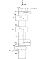
- FIG. 1 is a schematic configuration diagram of a refrigeration cycle apparatus including a cross-sectional view of the rotary compressor of the embodiment.
- the Z direction is the central axis direction of the shaft 13.
- the + Z direction (one side) is the direction from the compression mechanism unit 20 toward the motor unit 15, and the ⁇ Z direction (the other side) is the opposite side of the + Z direction.
- the Z direction is the vertical direction
- the + Z direction is the vertical upper direction.
- the X direction and the Y direction are the radial directions of the shaft 13.
- the X direction is the eccentric direction of the third eccentric portion 33 with respect to the central axis of the shaft 13.
- the X and Y directions are horizontal.
- the refrigeration cycle apparatus 1 will be briefly described.
- the refrigeration cycle device 1 includes a rotary compressor 2, a radiator (for example, a condenser) 3 connected to the rotary compressor 2, an expansion device (for example, an expansion valve) 4 connected to the radiator 3, and expansion. It has a heat absorber (for example, an evaporator) 5 connected to the device 4.
- the refrigeration cycle device 1 contains a refrigerant such as carbon dioxide (CO 2). The refrigerant circulates in the refrigeration cycle device 1 while changing the phase.
- CO 2 carbon dioxide
- the rotary compressor 2 is a so-called rotary compressor.
- the rotary compressor 2 compresses the low-pressure gas refrigerant (fluid) taken into the inside into a high-temperature, high-pressure gas refrigerant.
- the specific configuration of the rotary compressor 2 will be described later.
- the radiator 3 dissipates heat from the high-temperature / high-pressure gas refrigerant discharged from the rotary compressor 2 and turns the high-temperature / high-pressure gas refrigerant into a high-pressure liquid refrigerant.
- the expansion device 4 lowers the pressure of the high-pressure liquid refrigerant sent from the radiator 3 and turns the high-pressure liquid refrigerant into a low-temperature / low-pressure liquid refrigerant.
- the heat absorber 5 vaporizes the low-temperature / low-pressure liquid refrigerant sent from the expansion device 4 into a low-pressure gas refrigerant.
- the heat absorber 5 when the low-pressure liquid refrigerant vaporizes, the surroundings are cooled by removing the heat of vaporization from the surroundings.
- the low-pressure gaseous refrigerant that has passed through the heat absorber 5 is taken into the inside of the rotary compressor 2 described above.
- the refrigerant as the working fluid circulates between the gas refrigerant and the liquid refrigerant while changing the phase.
- the refrigerant dissipates heat in the process of phase change from gas refrigerant to liquid refrigerant, and absorbs heat in the process of phase change from liquid refrigerant to gas refrigerant. Heating and cooling are performed using these heat dissipation and heat absorption.
- the rotary compressor 2 will be described.
- the rotary compressor 2 includes an accumulator 6 and a compressor main body 10.
- the accumulator 6 separates the refrigerant sent from the heat absorber 5 into a gas refrigerant and a liquid refrigerant.
- the gaseous refrigerant is taken into the compressor main body 10 through the suction pipe.
- the compressor main body 10 includes a case 11, a shaft 13, an electric motor unit 15, and a plurality of compression mechanism units 20.
- the case 11 is formed in a cylindrical shape with both ends closed.
- the case 11 houses the shaft 13, the motor unit 15, and the plurality of compression mechanism units 20.
- the case 11 has a discharge portion 19 at the upper end portion.
- the discharge unit 19 supplies the gaseous refrigerant inside the case 11 to the radiator 3.
- the shaft 13 is arranged along the central axis of the compressor main body 10.
- the shaft 13 has a plurality of eccentric portions 30. Details of the plurality of eccentric portions 30 will be described later.
- the motor unit 15 is arranged in the + Z direction of the shaft 13.
- the motor unit 15 has a stator 15a and a rotor 15b.
- the stator 15a is fixed to the inner peripheral surface of the case 11.
- the rotor 15b is fixed to the outer peripheral surface of the shaft 13.
- the electric motor unit 15 drives the shaft 13 to rotate.
- the plurality of compression mechanism units 20 compress the gaseous refrigerant by the rotation of the shaft 13.
- the plurality of compression mechanism units 20 are arranged in the ⁇ Z direction of the shaft 13.
- the plurality of compression mechanism units 20 include three sets of compression mechanism units 20 of a first compression mechanism unit 21, a second compression mechanism unit 22, and a third compression mechanism unit 23.
- the first compression mechanism unit 21, the second compression mechanism unit 22, and the third compression mechanism unit 23 are arranged side by side in this order from the + Z direction to the ⁇ Z direction.
- the configuration of the first compression mechanism unit 21 will be described below as a representative.
- the configuration of the second compression mechanism portion 22 and the third compression mechanism portion 23 is the same as that of the first compression mechanism portion 21 except for the eccentric direction of the eccentric portion 30.
- the first compression mechanism portion 21 includes a first eccentric portion 31, a roller 35, and a cylinder 37.
- the first eccentric portion 31 has a columnar shape and is integrally formed with the shaft 13. When viewed from the + Z direction, the center of the first eccentric portion 31 is eccentric from the central axis of the shaft 13.
- the roller 35 is formed in a cylindrical shape and is arranged along the outer circumference of the first eccentric portion 31.
- the cylinder 37 is fixed to the frame 12.
- the outer peripheral surface of the frame 12 is fixed to the inner peripheral surface of the case 11.
- the cylinder 37 has a first cylinder chamber 21c, a vane (not shown), and a suction hole 39.
- the first cylinder chamber 21c is formed so as to penetrate the center of the cylinder 37 in the Z direction.
- the first cylinder chamber 21c houses the first eccentric portion 31 and the roller 35 inside.
- the vane is housed in a vane groove formed in the cylinder 37 and can move forward and backward inside the first cylinder chamber 21c. The vane is urged so that the tip end abuts on the outer peripheral surface of the roller 35.
- the vane together with the first eccentric portion 31 and the roller 35, partitions the inside of the first cylinder chamber 21c into a suction chamber and a compression chamber.
- the suction hole 39 takes in the gaseous refrigerant from the accumulator 6 into the suction chamber of the first cylinder chamber 21c.
- the rotary compressor 2 has a first bearing 17, a second bearing 18, a first partition 41, a second partition 42, a first muffler 27, and a second muffler 28.
- the first bearing 17 is arranged in the + Z direction of the plurality of compression mechanism portions 20 and supports the shaft 13.
- the second bearing 18 is arranged in the ⁇ Z direction of the plurality of compression mechanism portions 20 and supports the shaft 13.
- the first partition portion 41 is arranged between the first compression mechanism portion 21 and the second compression mechanism portion 22.
- the second partition portion 42 is arranged between the second compression mechanism portion 22 and the third compression mechanism portion 23.
- the first muffler 27 forms a first muffler chamber 27c with the first bearing 17.
- the gaseous refrigerant compressed by the first compression mechanism unit 21 is discharged to the first muffler chamber 27c.
- the gaseous refrigerant discharged into the first muffler chamber 27c is discharged into the case 11.
- the second muffler 28 forms a second muffler chamber 28c with the second bearing 18.
- the gaseous refrigerant compressed by the third compression mechanism unit 23 is discharged to the second muffler chamber 28c.
- the second muffler chamber 28c communicates with the first muffler chamber 27c via a passage between muffler chambers (not shown).
- the gaseous refrigerant compressed by the second compression mechanism portion 22 is discharged into the partition portion passage 46 formed in the second partition portion 42.
- the partition passage 46 communicates with the above-mentioned muffler chamber passage.
- the first region R1 is between the center of gravity 31 g of the first eccentric portion 31 and the center of gravity 32 g of the second eccentric portion 32.
- the second region R2 is located between the center of gravity 32 g of the second eccentric portion 32 and the center of gravity 33 g of the third eccentric portion 33.
- the distance of the second region R2 in the Z direction is larger than the distance of the first region R1 in the Z direction.
- An intermediate bearing 45 that supports the shaft 13 is arranged in the second region R2.
- the above-mentioned second partition 42 is arranged in the second region R2.
- the second partition portion 42 has a partition member 43 and an intermediate bearing 45.
- the partition member 43 is arranged in the ⁇ Z direction, and the intermediate bearing 45 is arranged in the + Z direction.
- the enlarged diameter portion 14 of the shaft 13 is formed at a position in the Z direction in which the intermediate bearing 45 is arranged.
- a through hole 47 formed in the center of the intermediate bearing 45 supports the enlarged diameter portion 14 of the shaft 13.
- a plurality of compression mechanism units 20 are arranged between the first bearing 17 and the second bearing 18.
- the deflection of the shaft 13 increases between the first bearing 17 and the second bearing 18.
- the intermediate bearing 45 is arranged near the center of the plurality of compression mechanism portions 20 in the Z direction. The intermediate bearing 45 suppresses the bending of the shaft 13. This makes it possible to provide a rotary compressor 2 having low vibration, high reliability, and high performance.
- the plurality of eccentric portions 30 have a first eccentric portion 31, a second eccentric portion 32, and a third eccentric portion 33.
- the first eccentric portion 31, the second eccentric portion 32, and the third eccentric portion 33 are arranged in the first compression mechanism portion 21, the second compression mechanism portion 22, and the third compression mechanism portion 23, respectively.
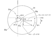
- FIG. 2 is a bottom view of a plurality of eccentric portions.
- the plurality of eccentric portions 30 are eccentric with respect to the central axis of the shaft 13.
- the eccentric directions of the plurality of eccentric portions 30 are different in the circumferential direction of the shaft 13. It is desirable that the eccentric directions of the plurality of eccentric portions 30 are equiangular intervals in the circumferential direction of the shaft 13.
- the eccentric directions of the first eccentric portion 31, the second eccentric portion 32, and the third eccentric portion 33 are equal angles of 120 ° in the circumferential direction of the shaft 13.
- the ⁇ direction is the rotation direction of the right-hand screw traveling in the + Z direction.
- the eccentric direction of the third eccentric portion 33 is the X direction.
- the eccentric direction of the second eccentric portion 32 is 120 ° in the ⁇ direction from the X direction, which is the eccentric direction of the third eccentric portion 33.
- the eccentric direction of the first eccentric portion 31 is 120 ° in the ⁇ direction from the eccentric direction of the second eccentric portion 32.
- centrifugal force F acts on the centers of gravity of the plurality of eccentric portions 30.
- the magnitudes of the centrifugal forces F acting on the plurality of eccentric portions 30 are the same.
- the X-direction component of the centrifugal force acting on the center of gravity 33 g of the third eccentric portion 33 is F, and the Y-direction component is 0.
- the X-direction component of the centrifugal force acting on the center of gravity 32 g of the second eccentric portion 32 is ⁇ F / 2
- the Y-direction component is ⁇ 3 ⁇ F / 2.
- the X-direction component of the centrifugal force acting on the center of gravity 31 g of the first eccentric portion 31 is ⁇ F / 2
- the Y-direction component is ⁇ 3 ⁇ F / 2.
- Centrifugal force F acting on the plurality of eccentric portions 30 causes a force moment (swinging moment, rotational moment) to act on the shaft 13.
- the rotary compressor 2 shown in FIG. 1 has a balancer (counter balancer) that suppresses the moment of the force acting on the shaft 13.
- the rotary compressor 2 has a first balancer 51 and a second balancer 52.
- the first balancer 51 and the second balancer 52 rotate together with the shaft 13.
- the second balancer 52 is arranged in the ⁇ Z direction of the first balancer 51.
- the plurality of eccentric portions 30 are arranged between the first balancer 51 and the second balancer 52 in the Z direction.
- the first balancer 51 is arranged in the + Z direction of the plurality of eccentric portions 30.
- the first balancer 51 is arranged in the + Z direction of the motor unit 15.
- the first balancer 51 is fixed to the end face of the rotor 15b of the motor unit 15 in the + Z direction.
- the first balancer 51 rotates together with the rotor 15b and the shaft 13.
- the second balancer 52 is arranged in the ⁇ Z direction of the plurality of eccentric portions 30.
- the second balancer 52 is arranged inside the second muffler 28 in the ⁇ Z direction of the second bearing 18.
- the second balancer 52 is formed separately from the shaft 13.
- the second balancer 52 is fixed to the shaft 13 by a fixing means such as a screw.
- the second balancer 52 rotates together with the shaft 13.
- FIG. 3 is a schematic front view of the shaft.
- FIG. 4 is a schematic side view of the shaft. 3 and 4 schematically show the shapes and positions of the shaft 13, the first balancer 51 and the second balancer 52 for ease of understanding.
- the first distance in the Z direction between the center of gravity 31 g of the first eccentric portion 31 and the center of gravity 32 g of the second eccentric portion 32 is L.
- the second distance in the Z direction between the center of gravity 32 g of the second eccentric portion 32 and the center of gravity 33 g of the third eccentric portion 33 is kL.
- k is the ratio of the second distance to the first distance.
- the distance in the Z direction between the center of gravity 51 g of the first balancer 51 and the center of gravity 52 g of the second balancer 52 is B.
- the X-direction component Fbx of the centrifugal force acting on the first balancer 51 is obtained so that the moment of the force acting on the shaft 13 around the Y-axis is set to 0.
- the center of gravity 33g of the third eccentric portion 33 is set as a reference point.
- the center of gravity 52 g of the second balancer 52 is set as a reference point.
- Fbx be the X-direction component of the centrifugal force acting on the first balancer 51 due to the rotation of the shaft 13.
- Mby B ⁇ Fbx ⁇ ⁇ ⁇ (2)
- the X-direction component of the centrifugal force acting on the second balancer 52 by the rotation of the shaft 13 is ⁇ Fbx.
- -Fbx is expressed by the formula 5.
- -Fbx -(2k + 1) LF / 2B ... (5)
- the mass, position, and shape of the second balancer 52 are set so that the X-direction component of the centrifugal force acting on the second balancer 52-Fbx satisfies Equation 5.
- the Y-direction component Fby of the centrifugal force acting on the first balancer 51 is obtained so that the moment of the force acting on the shaft 13 around the X-axis is set to 0.
- the center of gravity 33g of the third eccentric portion 33 is set as a reference point.
- the moment Mx of the force around the X axis acting on the shaft 13 due to the Y-direction component of the centrifugal force F acting on the plurality of eccentric portions 30 is expressed by Equation 6.
- Mx kL ⁇ - ⁇ 3 ⁇ F / 2 + (k + 1)
- L ⁇ ⁇ 3 ⁇ F / 2 ⁇ 3 ⁇ LF / 2 ⁇ ⁇ ⁇ (6)
- the center of gravity 52 g of the second balancer 52 is set as a reference point.
- Fby be the Y-direction component of the centrifugal force acting on the first balancer 51 due to the rotation of the shaft 13.
- the moment Mbx of the force around the X axis acting on the shaft 13 due to the Y-direction component Fby of the centrifugal force acting on the first balancer 51 is expressed by the mathematical formula 7.
- Mbx B ⁇ Fby ⁇ ⁇ ⁇ (7)
- the Y-direction component of the centrifugal force acting on the second balancer 52 by the rotation of the shaft 13 is ⁇ Fby.
- -Fby is represented by Equation 10.
- -Fby ⁇ 3 ⁇ LF / 2B ⁇ ⁇ ⁇ (10)
- the mass, position, and shape of the second balancer 52 are set so that the Y-direction component Fby of the centrifugal force acting on the second balancer 52 satisfies Equation 10.
- FIG. 5 is a bottom view of the first balancer.
- the X-direction component Fbx of the centrifugal force acting on the first balancer 51 such that the moment of force acting on the shaft 13 is set to 0 is expressed by Equation 4
- the Y-direction component Fby is expressed by Equation 9.
- the angle ⁇ 1 (rad) in the ⁇ direction in the eccentric direction of the center of gravity 51 g of the first balancer 51 with respect to the central axis of the shaft 13 with respect to the + X direction is expressed by Equation 11.
- ⁇ 1 arctan (A)
- A ⁇ 3 / (2k + 1) ... (11)
- the angle between the eccentric direction of the center of gravity 51g of the first balancer 51 with respect to the central axis of the shaft 13 and the eccentric direction of the centers of gravity of the plurality of eccentric portions 30 with respect to the central axis of the shaft 13 is defined as follows.
- the angle of the center of gravity 31g of the first eccentric portion 31 with respect to the eccentric direction is ⁇ 11.
- the angle of the center of gravity 32g of the second eccentric portion 32 with respect to the eccentric direction is ⁇ 12.
- the angle of the center of gravity 33g of the third eccentric portion 33 with respect to the eccentric direction is ⁇ 13.
- the angle between the eccentric direction of the center of gravity 51g of the first balancer 51 with respect to the central axis of the shaft 13 and the eccentric direction of the centers of gravity of the plurality of eccentric portions 30 with respect to the central axis of the shaft 13 satisfies Equation 12. ⁇ 13 ⁇ 12 ⁇ 11 ... (12) That is, it increases in the order of ⁇ 13, ⁇ 12, and ⁇ 11 from the smallest.
- the plurality of eccentric portions 30 and the first balancer 51 are set so as to satisfy the mathematical formula 12. Even when the eccentric directions of the plurality of eccentric portions 30 are not equiangular intervals, the moment of the force of the shaft 13 is suppressed by satisfying the mathematical formula 12. Even when the centrifugal force acting on the first balancer 51 does not satisfy the formula 4 or 9, the moment of the force of the shaft 13 is suppressed by satisfying the formula 12.
- FIG. 6 is a bottom view of the second balancer.
- the X-direction component-Fbx of the centrifugal force acting on the second balancer 52 such that the moment of force acting on the shaft 13 is set to 0 is expressed by Equation 5
- the Y-direction component-Fby is expressed by Equation 10. It is represented by.
- the angle ⁇ 2 (rad) in the ⁇ direction in the eccentric direction of the center of gravity 52 g of the second balancer 52 with respect to the central axis of the shaft 13 with respect to the + X direction is expressed by the mathematical formula 13.
- ⁇ 2 arctan (A) + ⁇
- A ⁇ 3 / (2k + 1) ⁇ ⁇ ⁇ (13)
- the angle between the eccentric direction of the center of gravity 52 g of the second balancer 52 with respect to the central axis of the shaft 13 and the eccentric direction of the centers of gravity of the plurality of eccentric portions 30 with respect to the central axis of the shaft 13 is defined as follows.
- the angle of the center of gravity 31g of the first eccentric portion 31 with respect to the eccentric direction is ⁇ 21.
- the angle of the center of gravity 32g of the second eccentric portion 32 with respect to the eccentric direction is ⁇ 22.
- the angle of the center of gravity 33g of the third eccentric portion 33 with respect to the eccentric direction is ⁇ 23.
- Equation 14 The angle between the eccentric direction of the center of gravity 52 g of the second balancer 52 with respect to the central axis of the shaft 13 and the eccentric direction of the centers of gravity of the plurality of eccentric portions 30 with respect to the central axis of the shaft 13 satisfies Equation 14. ⁇ 21 ⁇ 22 ⁇ 23 ... (14) That is, it increases in the order of ⁇ 21, ⁇ 22, and ⁇ 23 from the smallest.
- the plurality of eccentric portions 30 and the second balancer 52 are set so as to satisfy the mathematical formula 14. Even when the eccentric directions of the plurality of eccentric portions 30 are not equiangular intervals, the moment of the force of the shaft 13 is suppressed by satisfying the mathematical formula 14. Even when the centrifugal force acting on the second balancer 52 does not satisfy the formula 5 or 10, the moment of the force of the shaft 13 is suppressed by satisfying the formula 14.
- FIG. 7 is a graph showing the relationship between the deviation angle of the balancer and the vibration amplitude of the compressor body.
- the horizontal axis of FIG. 7 is the deviation angle (°) of the angles ⁇ 1 and ⁇ 2 of the balancers 51 and 52 described above.
- the vertical axis of FIG. 7 is the vibration amplitude ( ⁇ m) of the compressor main body 10.
- the vibration amplitude of the compressor main body 10 is 10 ⁇ m or less.
- the rotary compressor of the embodiment includes a shaft 13, a plurality of compression mechanism portions 20, a plurality of eccentric portions 30, a first balancer 51, and a second balancer 52.
- the plurality of eccentric portions 30 have a first eccentric portion 31, a second eccentric portion 32, and a third eccentric portion 33 arranged side by side in the ⁇ Z direction from the + Z direction in the central axis direction of the shaft 13.
- the second balancer 52 is arranged in the ⁇ Z direction of the first balancer 51.
- the angle between the eccentric direction of the first balancer 51 and the eccentric direction of the plurality of eccentric portions 30 satisfies Equation 12.
- the angle between the eccentric direction of the second balancer 52 and the eccentric direction of the plurality of eccentric portions 30 satisfies the formula 14.
- the moment of force of the shaft 13 generated by the three eccentric portions 31, 32, 33 is suppressed by the two balancers 51, 52.
- the vibration of the rotary compressor 2 is suppressed.
- the deterioration of reliability and performance of the rotary compressor 2 due to the bending of the shaft 13 is suppressed. Therefore, it is possible to provide a rotary compressor 2 having low vibration, high reliability, and high performance.
- ⁇ 1 (rad) be the angle in the eccentric direction of the first balancer 51 with respect to the + X direction.
- ⁇ 2 (rad) be the angle in the eccentric direction of the second balancer 52 with respect to the + X direction.
- ⁇ 1 and ⁇ 2 satisfy equations 15 and 16.
- the vibration amplitude of the compressor body 10 is suppressed to 10 ⁇ m or less. Therefore, the low vibration rotary compressor 2 can be provided by satisfying the equations 15 and 16.
- the plurality of eccentric portions 30 are arranged between the first balancer 51 and the second balancer 52 in the Z direction.
- the center of the force moment acting on the shaft 13 due to the centrifugal force of the plurality of eccentric portions 30 and the center of the force moment acting on the shaft 13 due to the centrifugal force of the two balancers 51 and 52 approach each other. Therefore, the bending of the shaft 13 due to the deviation of the center of the moment of force is suppressed. Therefore, it is possible to provide a rotary compressor 2 having low vibration, high reliability, and high performance.
- the intermediate bearing 45 that supports the shaft 13 is arranged in the region of R2 where the distance in the Z direction is large. Since the intermediate bearings 45 are arranged near the center of the plurality of compression mechanism portions 20, bending of the shaft 13 and the like are suppressed. This makes it possible to provide a rotary compressor 2 having low vibration, high reliability, and high performance.
- the rotary compressor 2 further includes an electric motor unit 15, a first bearing 17, and a second bearing 18.
- the first balancer 51 is arranged in the + Z direction of the motor unit 15.
- the second balancer 52 is arranged in the ⁇ Z direction of the second bearing 18. Since the distance between the balancers 51 and 52 becomes long, the mass of the balancers 51 and 52 is suppressed. As a result, the rotary compressor 2 can be made lighter, smaller, and resource-saving.
- the refrigeration cycle device 1 of the embodiment is connected to the rotary compressor 2 described above, a radiator 3 connected to the rotary compressor 2, an expansion device 4 connected to the radiator 3, and an expansion device 4. It also has a heat absorber 5. This makes it possible to provide a refrigeration cycle device 1 having low vibration, high reliability, and high performance.
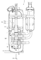
- FIG. 8 is a cross-sectional view of the rotary compressor of the first modification of the embodiment.
- the first modification differs from the embodiment in that the positions and shapes of the balancers 51 and 52 are different. Similar to the embodiment, the first balancer 51 and the second balancer 52 rotate together with the shaft 13. The second balancer 52 is arranged in the ⁇ Z direction of the first balancer 51. The plurality of eccentric portions 30 are arranged between the first balancer 51 and the second balancer 52 in the Z direction.
- the first balancer 51 is arranged in the + Z direction of the plurality of eccentric portions 30.
- the first balancer 51 is arranged in the ⁇ Z direction of the motor unit 15.
- the first balancer 51 is fixed to the end face of the rotor 15b of the motor unit 15 in the ⁇ Z direction.
- the second balancer 52 is arranged in the ⁇ Z direction of the plurality of eccentric portions 30.
- the second balancer 52 is arranged in the ⁇ Z direction of the second bearing 18.
- the surface of the second balancer 52 in the + Z direction is arranged along the surface of the second bearing 18 in the ⁇ Z direction.
- the rotary compressor 2 of the first modification satisfies equations 12, 14, 15 and 16.
- the plurality of eccentric portions 30 are arranged between the first balancer 51 and the second balancer 52 in the Z direction. This makes it possible to provide a rotary compressor 2 having low vibration, high reliability, and high performance.
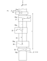
- FIG. 9 is a cross-sectional view of the rotary compressor of the second modification of the embodiment.
- the second modification differs from the embodiment in that the positions and shapes of the balancers 51 and 52 are different. Similar to the embodiment, the first balancer 51 and the second balancer 52 rotate together with the shaft 13. The second balancer 52 is arranged in the ⁇ Z direction of the first balancer 51.
- the first balancer 51 is arranged in the + Z direction of the plurality of eccentric portions 30.
- the first balancer 51 is arranged in the + Z direction of the motor unit 15.
- the first balancer 51 is fixed to the end face of the rotor 15b of the motor unit 15 in the + Z direction.
- the second balancer 52 is arranged in the + Z direction of the plurality of eccentric portions 30.
- the second balancer 52 is arranged in the ⁇ Z direction of the motor unit 15.
- the second balancer 52 is fixed to the end face of the rotor 15b of the motor unit 15 in the ⁇ Z direction.
- the rotary compressor 2 of the second modification satisfies equations 12, 14, 15 and 16. This makes it possible to provide a rotary compressor 2 having low vibration, high reliability, and high performance.
- the rotary compressor 2 of the embodiment shown in FIG. 1 is a so-called rotary compressor in which a blade (not shown) and a roller 35 are separate bodies.
- the rotary compressor may be a swing type compressor in which a blade and a roller are integrated.
- the balancers 51 and 52 satisfy the formulas 12 and 14. This makes it possible to provide a rotary compressor 2 having low vibration, high reliability, and high performance.
Landscapes
- Engineering & Computer Science (AREA)
- Mechanical Engineering (AREA)
- General Engineering & Computer Science (AREA)
- Physics & Mathematics (AREA)
- Thermal Sciences (AREA)
- Applications Or Details Of Rotary Compressors (AREA)
Abstract
Description
図1は、実施形態の回転式圧縮機の断面図を含む冷凍サイクル装置の概略構成図である。本願において、直交座標系のZ方向、X方向およびY方向が以下のように定義される。Z方向は、シャフト13の中心軸方向である。+Z方向(一方側)は圧縮機構部20から電動機部15に向かう方向であり、-Z方向(他方側)は+Z方向の反対側である。例えば、Z方向は鉛直方向であり、+Z方向は鉛直上方である。X方向およびY方向は、シャフト13の径方向である。X方向は、シャフト13の中心軸に対する第3偏心部33の偏心方向である。例えば、X方向およびY方向は水平方向である。
冷凍サイクル装置1は、回転式圧縮機2と、回転式圧縮機2に接続された放熱器(例えば凝縮器)3と、放熱器3に接続された膨張装置(例えば膨張弁)4と、膨張装置4に接続された吸熱器(例えば蒸発器)5と、を有する。冷凍サイクル装置1は、二酸化炭素(CO2)等の冷媒を含む。冷媒は、相変化しながら冷凍サイクル装置1を循環する。
膨張装置4は、放熱器3から送り込まれる高圧の液体冷媒の圧力を下げ、高圧の液体冷媒を低温・低圧の液体冷媒にする。
吸熱器5は、膨張装置4から送り込まれる低温・低圧の液体冷媒を気化させ、低圧の気体冷媒にする。吸熱器5において、低圧の液体冷媒が気化する際に周囲から気化熱を奪うことで周囲が冷却される。吸熱器5を通過した低圧の気体冷媒は、上述した回転式圧縮機2の内部に取り込まれる。
回転式圧縮機2は、アキュムレータ6と、圧縮機本体10と、を有する。アキュムレータ6は、吸熱器5から送り込まれる冷媒を、気体冷媒と液体冷媒とに分離する。気体冷媒は、吸入管を通って圧縮機本体10に取り込まれる。
ケース11は、両端部が閉塞された円筒状に形成される。ケース11は、シャフト13、電動機部15および複数の圧縮機構部20を収容する。ケース11は、上端部に吐出部19を有する。吐出部19は、ケース11の内部の気体冷媒を放熱器3に供給する。
電動機部15は、シャフト13の+Z方向に配置される。電動機部15は、固定子15aと、回転子15bと、を有する。固定子15aは、ケース11の内周面に固定される。回転子15bは、シャフト13の外周面に固定される。電動機部15は、シャフト13を回転駆動する。
第1偏心部31は、円柱状で、シャフト13と一体に形成される。+Z方向から見て、第1偏心部31の中心は、シャフト13の中心軸から偏心している。
ローラ35は、円筒状に形成され、第1偏心部31の外周に沿って配置される。
第1軸受17は、複数の圧縮機構部20の+Z方向に配置され、シャフト13を支持する。第2軸受18は、複数の圧縮機構部20の-Z方向に配置され、シャフト13を支持する。
第1仕切部41は、第1圧縮機構部21と第2圧縮機構部22との間に配置される。第2仕切部42は、第2圧縮機構部22と第3圧縮機構部23との間に配置される。
第2マフラ28は、第2軸受18との間に第2マフラ室28cを形成する。第3圧縮機構部23で圧縮された気体冷媒は、第2マフラ室28cに吐出される。第2マフラ室28cは、マフラ室間通路(不図示)を介して、第1マフラ室27cに連通している。
第2圧縮機構部22で圧縮された気体冷媒は、第2仕切部42に形成された仕切部通路46に吐出される。仕切部通路46は、前述したマフラ室間通路に連通している。
複数の偏心部30は、第1偏心部31、第2偏心部32および第3偏心部33を有する。第1偏心部31、第2偏心部32および第3偏心部33は、それぞれ第1圧縮機構部21、第2圧縮機構部22および第3圧縮機構部23に配置される。
前述したように、第3偏心部33の偏心方向はX方向である。第2偏心部32の偏心方向は、第3偏心部33の偏心方向であるX方向から、θ方向に120°の方向である。第1偏心部31の偏心方向は、第2偏心部32の偏心方向から、θ方向に120°の方向である。
第2バランサ52は、複数の偏心部30の-Z方向に配置される。第2バランサ52は、第2軸受18の-Z方向であって、第2マフラ28の内側に配置される。第2バランサ52は、シャフト13と別体に形成される。第2バランサ52は、ネジ等の固定手段によりシャフト13に固定される。第2バランサ52は、シャフト13と共に回転する。
My=kL・-F/2+(k+1)L・-F/2
=-(2k+1)LF/2 ・・・(1)
Mby=B・Fbx ・・・(2)
My+Mby=0 ・・・(3)
数式3を満たすFbxは、数式4で表される。
Fbx=(2k+1)LF/2B ・・・(4)
第1バランサ51に作用する遠心力のX方向成分Fbxが数式4を満たすように、第1バランサ51の質量、位置および形状が設定される。
-Fbx=-(2k+1)LF/2B ・・・(5)
第2バランサ52に作用する遠心力のX方向成分-Fbxが数式5を満たすように、第2バランサ52の質量、位置および形状が設定される。
Mx=kL・-√3・F/2+(k+1)L・√3・F/2
=√3・LF/2 ・・・(6)
Mbx=B・Fby ・・・(7)
Mx+Mbx=0 ・・・(8)
数式8を満たすFbyは、数式9で表される。
Fby=-√3・LF/2B ・・・(9)
第1バランサ51に作用する遠心力のY方向成分Fbyが数式9を満たすように、第1バランサ51の質量、位置および形状が設定される。
-Fby=√3・LF/2B ・・・(10)
第2バランサ52に作用する遠心力のY方向成分Fbyが数式10を満たすように、第2バランサ52の質量、位置および形状が設定される。
θ1=arctan(A)、A=√3/(2k+1) ・・・(11)
θ13<θ12<θ11 ・・・(12)
すなわち、小さい方からθ13、θ12、θ11の順に大きくなる。
θ2=arctan(A)+π、A=√3/(2k+1) ・・・(13)
θ21<θ22<θ23 ・・・(14)
すなわち、小さい方からθ21、θ22、θ23の順に大きくなる。
arctan(A)-π/36 ≦θ1≦arctan(A)+π/36 ・・(15)
arctan(A)+π-π/36≦θ2≦arctan(A)+π+π/36 ・・(16)
複数の偏心部30の遠心力によりシャフト13に作用する力のモーメントの中心と、2個のバランサ51,52の遠心力によりシャフト13に作用する力のモーメントの中心とが接近する。そのため、力のモーメントの中心のズレによるシャフト13の撓み等が抑制される。したがって、低振動、高信頼性、高性能の回転式圧縮機2を提供することができる。
複数の圧縮機構部20の中央付近に中間軸受45が配置されるので、シャフト13の撓み等が抑制される。これにより、低振動、高信頼性、高性能の回転式圧縮機2を提供することができる。
各バランサ51,52の間の距離が長くなるので、各バランサ51,52の質量が抑制される。これにより、回転式圧縮機2の軽量化、小型化、省資源化を図ることができる。
これにより、低振動、高信頼性、高性能の冷凍サイクル装置1を提供することができる。
実施形態と同様に、第1バランサ51および第2バランサ52は、シャフト13と共に回転する。第2バランサ52は、第1バランサ51の-Z方向に配置される。複数の偏心部30は、Z方向において第1バランサ51と第2バランサ52との間に配置される。
第2バランサ52は、複数の偏心部30の-Z方向に配置される。第2バランサ52は、第2軸受18の-Z方向に配置される。第2バランサ52の+Z方向の表面は、第2軸受18の-Z方向の表面に沿って配置される。
実施形態と同様に、第1バランサ51および第2バランサ52は、シャフト13と共に回転する。第2バランサ52は、第1バランサ51の-Z方向に配置される。
第2バランサ52は、複数の偏心部30の+Z方向に配置される。第2バランサ52は、電動機部15の-Z方向に配置される。第2バランサ52は、電動機部15の回転子15bの-Z方向の端面に固定される。
Claims (6)
- 中心軸の周りに回転可能なシャフトと、
前記シャフトの中心軸方向の一方側から他方側に並んで配置された第1圧縮機構部、第2圧縮機構部および第3圧縮機構部を有する複数の圧縮機構部と、
前記シャフトに設けられ、前記第1圧縮機構部、前記第2圧縮機構部および前記第3圧縮機構部にそれぞれ配置された第1偏心部、第2偏心部および第3偏心部を有する複数の偏心部と、
前記シャフトと共に回転する第1バランサと、
前記第1バランサの前記他方側に配置され、前記シャフトと共に回転する第2バランサと、を備え、
前記シャフトの中心軸に対する前記第1バランサの偏心方向と、前記シャフトの中心軸に対する前記複数の偏心部の偏心方向との角度が、前記第3偏心部、前記第2偏心部、前記第1偏心部の順に大きくなり、
前記シャフトの中心軸に対する前記第2バランサの偏心方向と、前記シャフトの中心軸に対する前記複数の偏心部の偏心方向との角度が、前記第1偏心部、前記第2偏心部、前記第3偏心部の順に大きくなる、
回転式圧縮機。 - 前記第1偏心部の重心と前記第2偏心部の重心との間の前記中心軸方向の距離に対する、前記第2偏心部の重心と前記第3偏心部の重心との間の前記中心軸方向の距離の割合をkとし、
前記シャフトの中心軸に対する前記第3偏心部の偏心方向と、前記シャフトの中心軸に対する前記第1バランサの偏心方向との角度をθ1(rad)とし、
前記シャフトの中心軸に対する前記第3偏心部の偏心方向と、前記シャフトの中心軸に対する前記第2バランサの偏心方向との角度をθ2(rad)としたとき、
arctan(A)-π/36 ≦θ1≦arctan(A)+π/36
arctan(A)+π-π/36≦θ2≦arctan(A)+π+π/36
A=√3/(2k+1)
を満たす、
請求項1に記載の回転式圧縮機。 - 前記複数の偏心部は、前記中心軸方向において前記第1バランサと前記第2バランサとの間に配置される、
請求項1または2に記載の回転式圧縮機。 - 前記第1偏心部の重心と前記第2偏心部の重心との間の第1領域および前記第2偏心部の重心と前記第3偏心部の重心との間の第2領域のうち、前記中心軸方向の距離が大きい方の領域に、前記シャフトを支持する中間軸受が配置される、
請求項1から3のいずれか1項に記載の回転式圧縮機。 - 前記複数の圧縮機構部の前記一方側に配置され、前記シャフトを回転駆動する電動機部と、
前記複数の圧縮機構部の前記一方側に配置され、前記シャフトを支持する第1軸受と、
前記複数の圧縮機構部の前記他方側に配置され、前記シャフトを支持する第2軸受と、をさらに有し、
前記第1バランサは、前記電動機部の前記一方側に配置され、
前記第2バランサは、前記第2軸受の前記他方側に配置される、
請求項1から4のいずれか1項に記載の回転式圧縮機。 - 請求項1から5のいずれか1項に記載の回転式圧縮機と、
前記回転式圧縮機に接続された放熱器と、
前記放熱器に接続された膨張装置と、
前記膨張装置に接続された吸熱器と、を有する、
冷凍サイクル装置。
Priority Applications (5)
| Application Number | Priority Date | Filing Date | Title |
|---|---|---|---|
| PCT/JP2020/007348 WO2021171340A1 (ja) | 2020-02-25 | 2020-02-25 | 回転式圧縮機および冷凍サイクル装置 |
| CN202080076436.2A CN114630963B (zh) | 2020-02-25 | 2020-02-25 | 旋转式压缩机以及冷冻循环装置 |
| EP20921005.3A EP4112939B1 (en) | 2020-02-25 | 2020-02-25 | Rotary compressor and refrigeration cycle device |
| JP2022502348A JP7389220B2 (ja) | 2020-02-25 | 2020-02-25 | 回転式圧縮機および冷凍サイクル装置 |
| US17/819,020 US12140347B2 (en) | 2020-02-25 | 2022-08-11 | Rotary compressor and refrigeration cycle device |
Applications Claiming Priority (1)
| Application Number | Priority Date | Filing Date | Title |
|---|---|---|---|
| PCT/JP2020/007348 WO2021171340A1 (ja) | 2020-02-25 | 2020-02-25 | 回転式圧縮機および冷凍サイクル装置 |
Related Child Applications (1)
| Application Number | Title | Priority Date | Filing Date |
|---|---|---|---|
| US17/819,020 Continuation US12140347B2 (en) | 2020-02-25 | 2022-08-11 | Rotary compressor and refrigeration cycle device |
Publications (1)
| Publication Number | Publication Date |
|---|---|
| WO2021171340A1 true WO2021171340A1 (ja) | 2021-09-02 |
Family
ID=77491278
Family Applications (1)
| Application Number | Title | Priority Date | Filing Date |
|---|---|---|---|
| PCT/JP2020/007348 Ceased WO2021171340A1 (ja) | 2020-02-25 | 2020-02-25 | 回転式圧縮機および冷凍サイクル装置 |
Country Status (5)
| Country | Link |
|---|---|
| US (1) | US12140347B2 (ja) |
| EP (1) | EP4112939B1 (ja) |
| JP (1) | JP7389220B2 (ja) |
| CN (1) | CN114630963B (ja) |
| WO (1) | WO2021171340A1 (ja) |
Families Citing this family (1)
| Publication number | Priority date | Publication date | Assignee | Title |
|---|---|---|---|---|
| CN118974409A (zh) * | 2022-03-31 | 2024-11-15 | 大金工业株式会社 | 压缩机及制冷装置 |
Citations (4)
| Publication number | Priority date | Publication date | Assignee | Title |
|---|---|---|---|---|
| CN103452844A (zh) * | 2012-06-04 | 2013-12-18 | 广东美芝制冷设备有限公司 | 旋转压缩机 |
| JP2014129755A (ja) * | 2012-12-28 | 2014-07-10 | Daikin Ind Ltd | ロータリ式圧縮機 |
| WO2019171540A1 (ja) * | 2018-03-08 | 2019-09-12 | 株式会社 東芝 | ロータリコンプレッサおよび冷凍サイクル装置 |
| WO2019186695A1 (ja) | 2018-03-27 | 2019-10-03 | 東芝キヤリア株式会社 | ロータリコンプレッサおよび冷凍サイクル装置 |
Family Cites Families (10)
| Publication number | Priority date | Publication date | Assignee | Title |
|---|---|---|---|---|
| JPH05187374A (ja) * | 1992-01-13 | 1993-07-27 | Sanyo Electric Co Ltd | 密閉型圧縮機 |
| JPH0610863A (ja) * | 1992-06-26 | 1994-01-21 | Daikin Ind Ltd | 3気筒型ロータリー圧縮機 |
| KR19980073118A (ko) * | 1997-03-12 | 1998-11-05 | 구자홍 | 로터리 압축기의 밸런서 |
| JP2004270654A (ja) * | 2003-03-12 | 2004-09-30 | Denso Corp | 回転型圧縮機 |
| JP2008063973A (ja) * | 2006-09-05 | 2008-03-21 | Toshiba Kyaria Kk | 2気筒回転圧縮機、冷凍サイクル装置 |
| JP5304868B2 (ja) * | 2011-09-30 | 2013-10-02 | ダイキン工業株式会社 | スクロール圧縮機 |
| JP6077352B2 (ja) * | 2013-03-26 | 2017-02-08 | 東芝キヤリア株式会社 | 多気筒回転式圧縮機及び冷凍サイクル装置 |
| WO2016017281A1 (ja) * | 2014-08-01 | 2016-02-04 | 東芝キヤリア株式会社 | 回転式圧縮機及び冷凍サイクル装置 |
| CN104728118B (zh) * | 2015-04-01 | 2017-06-16 | 广东美芝制冷设备有限公司 | 旋转式压缩机 |
| CN204532830U (zh) * | 2015-04-01 | 2015-08-05 | 广东美芝制冷设备有限公司 | 旋转式压缩机 |
-
2020
- 2020-02-25 CN CN202080076436.2A patent/CN114630963B/zh active Active
- 2020-02-25 JP JP2022502348A patent/JP7389220B2/ja active Active
- 2020-02-25 WO PCT/JP2020/007348 patent/WO2021171340A1/ja not_active Ceased
- 2020-02-25 EP EP20921005.3A patent/EP4112939B1/en active Active
-
2022
- 2022-08-11 US US17/819,020 patent/US12140347B2/en active Active
Patent Citations (4)
| Publication number | Priority date | Publication date | Assignee | Title |
|---|---|---|---|---|
| CN103452844A (zh) * | 2012-06-04 | 2013-12-18 | 广东美芝制冷设备有限公司 | 旋转压缩机 |
| JP2014129755A (ja) * | 2012-12-28 | 2014-07-10 | Daikin Ind Ltd | ロータリ式圧縮機 |
| WO2019171540A1 (ja) * | 2018-03-08 | 2019-09-12 | 株式会社 東芝 | ロータリコンプレッサおよび冷凍サイクル装置 |
| WO2019186695A1 (ja) | 2018-03-27 | 2019-10-03 | 東芝キヤリア株式会社 | ロータリコンプレッサおよび冷凍サイクル装置 |
Non-Patent Citations (1)
| Title |
|---|
| See also references of EP4112939A4 |
Also Published As
| Publication number | Publication date |
|---|---|
| US20220390153A1 (en) | 2022-12-08 |
| JP7389220B2 (ja) | 2023-11-29 |
| JPWO2021171340A1 (ja) | 2021-09-02 |
| EP4112939A1 (en) | 2023-01-04 |
| CN114630963B (zh) | 2024-07-02 |
| US12140347B2 (en) | 2024-11-12 |
| EP4112939A4 (en) | 2023-11-08 |
| EP4112939B1 (en) | 2025-07-23 |
| CN114630963A (zh) | 2022-06-14 |
Similar Documents
| Publication | Publication Date | Title |
|---|---|---|
| JP5441982B2 (ja) | 回転圧縮機 | |
| JP4897867B2 (ja) | 多シリンダロータリ圧縮機及びその製造方法 | |
| WO2014155938A1 (ja) | 多気筒回転式圧縮機及び冷凍サイクル装置 | |
| US20200333055A1 (en) | Compressor and refrigeration cycle device | |
| US12140347B2 (en) | Rotary compressor and refrigeration cycle device | |
| WO2017065032A1 (ja) | 圧縮機 | |
| JP2004270654A (ja) | 回転型圧縮機 | |
| ES2551406T3 (es) | Compresor hermético | |
| JP6454177B2 (ja) | 回転式圧縮機及び冷凍サイクル装置 | |
| JPWO2018216654A1 (ja) | 密閉型冷媒圧縮機および冷凍装置 | |
| US11466687B2 (en) | Rotary compressor and refrigeration cycle apparatus | |
| WO2016017281A1 (ja) | 回転式圧縮機及び冷凍サイクル装置 | |
| CN108980044A (zh) | 压缩机及具有其的空调器 | |
| JP6758412B2 (ja) | 回転式圧縮機および冷凍サイクル装置 | |
| JP6619658B2 (ja) | 回転式圧縮機及び冷凍サイクル装置 | |
| WO2019102748A1 (ja) | ロータリ圧縮機 | |
| JP2006233860A (ja) | 油分離装置及び圧縮機、並びに空気調和装置 | |
| JP2015055187A (ja) | 圧縮機および冷凍サイクル装置 | |
| JP2024073799A (ja) | 圧縮機および冷凍サイクル装置 | |
| KR20240056229A (ko) | 스크롤 압축 장치 | |
| JP4855118B2 (ja) | 可変容量型圧縮機 | |
| WO2026070622A1 (ja) | ロータリ圧縮機及び冷凍装置 | |
| WO2003029673A1 (en) | Rotary machine | |
| JP2020118053A (ja) | 回転式圧縮機および冷凍サイクル装置 | |
| WO2021100141A1 (ja) | スクロール圧縮機および冷凍サイクル装置 |
Legal Events
| Date | Code | Title | Description |
|---|---|---|---|
| 121 | Ep: the epo has been informed by wipo that ep was designated in this application |
Ref document number: 20921005 Country of ref document: EP Kind code of ref document: A1 |
|
| ENP | Entry into the national phase |
Ref document number: 2022502348 Country of ref document: JP Kind code of ref document: A |
|
| NENP | Non-entry into the national phase |
Ref country code: DE |
|
| ENP | Entry into the national phase |
Ref document number: 2020921005 Country of ref document: EP Effective date: 20220926 |
|
| WWG | Wipo information: grant in national office |
Ref document number: 2020921005 Country of ref document: EP |