WO2021172143A1 - 検査方法、並びに二次電池用積層体の製造方法及び二次電池の製造方法 - Google Patents
検査方法、並びに二次電池用積層体の製造方法及び二次電池の製造方法 Download PDFInfo
- Publication number
- WO2021172143A1 WO2021172143A1 PCT/JP2021/006000 JP2021006000W WO2021172143A1 WO 2021172143 A1 WO2021172143 A1 WO 2021172143A1 JP 2021006000 W JP2021006000 W JP 2021006000W WO 2021172143 A1 WO2021172143 A1 WO 2021172143A1
- Authority
- WO
- WIPO (PCT)
- Prior art keywords
- secondary battery
- separator
- paint
- adhesive material
- electrode
- Prior art date
- Legal status (The legal status is an assumption and is not a legal conclusion. Google has not performed a legal analysis and makes no representation as to the accuracy of the status listed.)
- Ceased
Links
Images
Classifications
-
- H—ELECTRICITY
- H01—ELECTRIC ELEMENTS
- H01M—PROCESSES OR MEANS, e.g. BATTERIES, FOR THE DIRECT CONVERSION OF CHEMICAL ENERGY INTO ELECTRICAL ENERGY
- H01M50/00—Constructional details or processes of manufacture of the non-active parts of electrochemical cells other than fuel cells, e.g. hybrid cells
- H01M50/40—Separators; Membranes; Diaphragms; Spacing elements inside cells
- H01M50/46—Separators, membranes or diaphragms characterised by their combination with electrodes
- H01M50/461—Separators, membranes or diaphragms characterised by their combination with electrodes with adhesive layers between electrodes and separators
-
- B—PERFORMING OPERATIONS; TRANSPORTING
- B32—LAYERED PRODUCTS
- B32B—LAYERED PRODUCTS, i.e. PRODUCTS BUILT-UP OF STRATA OF FLAT OR NON-FLAT, e.g. CELLULAR OR HONEYCOMB, FORM
- B32B37/00—Methods or apparatus for laminating, e.g. by curing or by ultrasonic bonding
- B32B37/12—Methods or apparatus for laminating, e.g. by curing or by ultrasonic bonding characterised by using adhesives
- B32B37/1284—Application of adhesive
-
- B—PERFORMING OPERATIONS; TRANSPORTING
- B32—LAYERED PRODUCTS
- B32B—LAYERED PRODUCTS, i.e. PRODUCTS BUILT-UP OF STRATA OF FLAT OR NON-FLAT, e.g. CELLULAR OR HONEYCOMB, FORM
- B32B41/00—Arrangements for controlling or monitoring lamination processes; Safety arrangements
-
- G—PHYSICS
- G01—MEASURING; TESTING
- G01B—MEASURING LENGTH, THICKNESS OR SIMILAR LINEAR DIMENSIONS; MEASURING ANGLES; MEASURING AREAS; MEASURING IRREGULARITIES OF SURFACES OR CONTOURS
- G01B11/00—Measuring arrangements characterised by the use of optical techniques
- G01B11/24—Measuring arrangements characterised by the use of optical techniques for measuring contours or curvatures
-
- H—ELECTRICITY
- H01—ELECTRIC ELEMENTS
- H01M—PROCESSES OR MEANS, e.g. BATTERIES, FOR THE DIRECT CONVERSION OF CHEMICAL ENERGY INTO ELECTRICAL ENERGY
- H01M10/00—Secondary cells; Manufacture thereof
- H01M10/04—Construction or manufacture in general
-
- H—ELECTRICITY
- H01—ELECTRIC ELEMENTS
- H01M—PROCESSES OR MEANS, e.g. BATTERIES, FOR THE DIRECT CONVERSION OF CHEMICAL ENERGY INTO ELECTRICAL ENERGY
- H01M10/00—Secondary cells; Manufacture thereof
- H01M10/05—Accumulators with non-aqueous electrolyte
- H01M10/052—Li-accumulators
-
- H—ELECTRICITY
- H01—ELECTRIC ELEMENTS
- H01M—PROCESSES OR MEANS, e.g. BATTERIES, FOR THE DIRECT CONVERSION OF CHEMICAL ENERGY INTO ELECTRICAL ENERGY
- H01M10/00—Secondary cells; Manufacture thereof
- H01M10/05—Accumulators with non-aqueous electrolyte
- H01M10/058—Construction or manufacture
-
- H—ELECTRICITY
- H01—ELECTRIC ELEMENTS
- H01M—PROCESSES OR MEANS, e.g. BATTERIES, FOR THE DIRECT CONVERSION OF CHEMICAL ENERGY INTO ELECTRICAL ENERGY
- H01M4/00—Electrodes
- H01M4/02—Electrodes composed of, or comprising, active material
- H01M4/13—Electrodes for accumulators with non-aqueous electrolyte, e.g. for lithium-accumulators; Processes of manufacture thereof
- H01M4/139—Processes of manufacture
-
- H—ELECTRICITY
- H01—ELECTRIC ELEMENTS
- H01M—PROCESSES OR MEANS, e.g. BATTERIES, FOR THE DIRECT CONVERSION OF CHEMICAL ENERGY INTO ELECTRICAL ENERGY
- H01M50/00—Constructional details or processes of manufacture of the non-active parts of electrochemical cells other than fuel cells, e.g. hybrid cells
- H01M50/40—Separators; Membranes; Diaphragms; Spacing elements inside cells
- H01M50/403—Manufacturing processes of separators, membranes or diaphragms
-
- B—PERFORMING OPERATIONS; TRANSPORTING
- B32—LAYERED PRODUCTS
- B32B—LAYERED PRODUCTS, i.e. PRODUCTS BUILT-UP OF STRATA OF FLAT OR NON-FLAT, e.g. CELLULAR OR HONEYCOMB, FORM
- B32B2457/00—Electrical equipment
- B32B2457/10—Batteries
-
- B—PERFORMING OPERATIONS; TRANSPORTING
- B32—LAYERED PRODUCTS
- B32B—LAYERED PRODUCTS, i.e. PRODUCTS BUILT-UP OF STRATA OF FLAT OR NON-FLAT, e.g. CELLULAR OR HONEYCOMB, FORM
- B32B37/00—Methods or apparatus for laminating, e.g. by curing or by ultrasonic bonding
- B32B37/14—Methods or apparatus for laminating, e.g. by curing or by ultrasonic bonding characterised by the properties of the layers
-
- B—PERFORMING OPERATIONS; TRANSPORTING
- B32—LAYERED PRODUCTS
- B32B—LAYERED PRODUCTS, i.e. PRODUCTS BUILT-UP OF STRATA OF FLAT OR NON-FLAT, e.g. CELLULAR OR HONEYCOMB, FORM
- B32B37/00—Methods or apparatus for laminating, e.g. by curing or by ultrasonic bonding
- B32B37/14—Methods or apparatus for laminating, e.g. by curing or by ultrasonic bonding characterised by the properties of the layers
- B32B37/16—Methods or apparatus for laminating, e.g. by curing or by ultrasonic bonding characterised by the properties of the layers with all layers existing as coherent layers before laminating
- B32B37/20—Methods or apparatus for laminating, e.g. by curing or by ultrasonic bonding characterised by the properties of the layers with all layers existing as coherent layers before laminating involving the assembly of continuous webs only
-
- H—ELECTRICITY
- H01—ELECTRIC ELEMENTS
- H01M—PROCESSES OR MEANS, e.g. BATTERIES, FOR THE DIRECT CONVERSION OF CHEMICAL ENERGY INTO ELECTRICAL ENERGY
- H01M10/00—Secondary cells; Manufacture thereof
- H01M10/05—Accumulators with non-aqueous electrolyte
- H01M10/052—Li-accumulators
- H01M10/0525—Rocking-chair batteries, i.e. batteries with lithium insertion or intercalation in both electrodes; Lithium-ion batteries
-
- Y—GENERAL TAGGING OF NEW TECHNOLOGICAL DEVELOPMENTS; GENERAL TAGGING OF CROSS-SECTIONAL TECHNOLOGIES SPANNING OVER SEVERAL SECTIONS OF THE IPC; TECHNICAL SUBJECTS COVERED BY FORMER USPC CROSS-REFERENCE ART COLLECTIONS [XRACs] AND DIGESTS
- Y02—TECHNOLOGIES OR APPLICATIONS FOR MITIGATION OR ADAPTATION AGAINST CLIMATE CHANGE
- Y02E—REDUCTION OF GREENHOUSE GAS [GHG] EMISSIONS, RELATED TO ENERGY GENERATION, TRANSMISSION OR DISTRIBUTION
- Y02E60/00—Enabling technologies; Technologies with a potential or indirect contribution to GHG emissions mitigation
- Y02E60/10—Energy storage using batteries
-
- Y—GENERAL TAGGING OF NEW TECHNOLOGICAL DEVELOPMENTS; GENERAL TAGGING OF CROSS-SECTIONAL TECHNOLOGIES SPANNING OVER SEVERAL SECTIONS OF THE IPC; TECHNICAL SUBJECTS COVERED BY FORMER USPC CROSS-REFERENCE ART COLLECTIONS [XRACs] AND DIGESTS
- Y02—TECHNOLOGIES OR APPLICATIONS FOR MITIGATION OR ADAPTATION AGAINST CLIMATE CHANGE
- Y02P—CLIMATE CHANGE MITIGATION TECHNOLOGIES IN THE PRODUCTION OR PROCESSING OF GOODS
- Y02P70/00—Climate change mitigation technologies in the production process for final industrial or consumer products
- Y02P70/50—Manufacturing or production processes characterised by the final manufactured product
Definitions
- the present invention relates to a method of inspecting a poor coating of an adhesive material on the surface of a battery member, and a method of manufacturing a laminate for a secondary battery and a secondary battery through the inspection.
- Secondary batteries such as lithium-ion secondary batteries are small and lightweight, have high energy density, and can be repeatedly charged and discharged, and are used in a wide range of applications.
- a secondary battery generally includes a positive electrode, a negative electrode, and a battery member such as a separator that separates the positive electrode and the negative electrode to prevent a short circuit between the positive electrode and the negative electrode.
- the electrode and the separator before being immersed in the electrolytic solution are crimped to form a laminate (hereinafter, may be referred to as a “laminate for secondary battery”), which is necessary.
- a laminate for secondary battery a laminate
- it may be cut to the desired size, laminated, folded or wound.
- the crimped electrode and the separator may be misaligned, which may cause problems such as defects and a decrease in productivity.
- Patent Document 1 a paint containing a predetermined thermoplastic polymer is applied to a separator, and the coating film is dried to remove a solvent in the coating liquid to produce a separator having an adhesive material on the surface. ..
- the battery members are bonded to each other via the adhesive material, there may be a portion where the adhesive material is not unintentionally formed (application defective portion) due to poor coating of the paint.
- the bonded surface on which the adhesive material is formed by drying may be inspected with a CCD camera or the like before bonding.
- it is required to identify a poorly applied portion with higher accuracy.
- it has been attempted to reduce the amount of adhesive material formed which can be a resistance component.
- the amount of paint used is reduced in order to reduce the amount of adhesive material formed, the adhesive material formed after drying will be buried in the unevenness of the bonded surface. It became clear by the examination of the present inventor that it is difficult to identify.
- the present invention is a new technique capable of sufficiently suppressing bonding defects by identifying poorly coated parts with high accuracy in manufacturing a laminate for a secondary battery in which battery members are bonded to each other via an adhesive material.
- the purpose is to provide.
- the present inventor conducted a diligent study for the purpose of solving the above problems.
- the present invention aims to advantageously solve the above problems, and the inspection method of the present invention applies a coating material containing a binder and a solvent to at least one bonding surface of the electrode and the separator.
- An inspection method used when forming the adhesive material on the bonded surface through a step of applying and a step of drying the paint applied to the bonded surface to form an adhesive material.
- the step of forming the adhesive material Prior to the step of forming the adhesive material, it is characterized by comprising a step of measuring the displacement of the bonded surface to which the paint is applied with a laser displacement meter and identifying a poorly applied portion.
- the paint before drying tends to have a larger displacement (height) of the solvent removed by drying from the bonded surface than the adhesive material formed after drying.
- the difference in displacement between the coated part and the poorly applied part becomes clear, and the defectively applied part can be identified with high accuracy.
- the production line is immediately stopped, the cause of the defective coating parts (clogging of the coating nozzle, etc.) is investigated, and the said. It is possible to take prompt action such as removing the cause. As a result, it is possible to reduce the rate of occurrence of poor bonding between the electrodes and the separator.
- the average height of the paint from the bonded surface is 2 ⁇ m or more and 150 ⁇ m or less in the step of applying the paint.
- the average height of the paint applied to the bonded surface is within the above-mentioned range, the difference in displacement between the coated portion and the poorly coated portion becomes clearer, and as a result, the accuracy of identifying the defective coating portion can be improved.
- the drying efficiency of the paint can be improved.
- the "average height of the paint from the bonded surface" of the paint can be calculated as an average value of the heights of any 1000 points of the paint measured by a laser displacement meter or the like.
- the adhesive material in the step of forming the adhesive material, is formed in a dot shape, and the average diameter of the adhesive material formed in the dot shape is 5 ⁇ m or more and 300 ⁇ m or less. It is preferable to have.
- the average diameter of the dot-shaped adhesive material applied to the bonding surface is within the above-mentioned range, the electrode and the separator can be bonded well.
- the "average diameter of the adhesive material formed in a dot shape" is the maximum diameter (1) of any 1000 dots in the plan view image of the bonded surface obtained by observation with a laser microscope or the like. It can be calculated as the average value of the maximum length of the line segment connecting two points on the outer edge of one dot.
- the solid content concentration of the paint is 20% by mass or less in the step of applying the paint.
- a paint having a solid content concentration of 20% by mass or less is excellent in handleability without excessively increasing the viscosity. Therefore, it is possible to sufficiently suppress the occurrence of poor coating and reduce the rate of poor bonding of the electrode and the separator.
- the coating is performed by an inkjet method in the step of applying the coating material.
- the inkjet method has an excellent degree of freedom in the shape (coating shape) in which the paint is applied, and if the paint is applied by the inkjet method, the productivity of the laminate can be sufficiently ensured.
- the present invention aims to advantageously solve the above problems, and the method for producing a laminate for a secondary battery of the present invention is for a secondary battery in which an electrode and a separator are bonded together.
- a method for producing a laminate wherein an inspection is performed according to any of the above-mentioned inspection methods, and after the inspection, the electrode and the separator are passed through the bonding surface on which the adhesive material is formed. It is characterized by including a process of bonding and. If the inspection is carried out according to the above-mentioned inspection method, if a large number of defective coating parts occur, the production line can be immediately stopped and the problem can be solved promptly. As a result, the rate of occurrence of poor bonding between the electrodes and the separator can be reduced, and the laminated body can be efficiently manufactured.
- the present invention aims to advantageously solve the above problems, and the method for manufacturing a secondary battery of the present invention is to use a laminated body for a secondary battery in which an electrode and a separator are bonded together.
- a method for manufacturing a secondary battery which comprises a step of manufacturing the laminated battery for a secondary battery by using the above-described method for manufacturing a laminated battery for a secondary battery, the laminated battery for a secondary battery, and an electrolytic solution. It is characterized by including a step of assembling a secondary battery using the above.
- the laminate manufactured according to the above-mentioned manufacturing method of the laminate the occurrence rate of poor bonding between the electrode and the separator is reduced. Therefore, if the laminate is used, a secondary battery having excellent battery characteristics can be efficiently manufactured. can do.
- the inspection method of the present invention when manufacturing a laminate for a secondary battery in which battery members are bonded to each other via an adhesive material, it is possible to identify a poorly applied portion with high accuracy. Further, according to the method for manufacturing a laminated body for a secondary battery of the present invention, it is possible to efficiently manufacture a laminated body for a secondary battery by reducing the occurrence rate of poor bonding between the electrode and the separator. Then, according to the method for manufacturing a secondary battery of the present invention, a secondary battery having excellent battery characteristics can be efficiently manufactured.
- the inspection method of the present invention is a coating defective portion on the bonded surface of the electrode and / or the separator when the electrode (positive electrode and / or the negative electrode) and the separator are bonded to each other to manufacture a laminate for a secondary battery. Can be used to identify.
- the method for producing a laminate for a secondary battery of the present invention is a method for producing a laminate for a secondary battery through an inspection according to the above-described inspection method of the present invention, and the laminate for a secondary battery is continuously produced. It can be particularly preferably used in the production.
- a non-aqueous secondary battery for example, lithium ion secondary
- a non-aqueous secondary battery for example, lithium ion secondary
- a secondary battery manufactured according to the above-described method for manufacturing a laminated battery for a secondary battery of the present invention It can be used when manufacturing a secondary battery such as a secondary battery).
- the inspection method of the present invention is used in the process of manufacturing a laminate for a secondary battery.
- the manufacturing process of the laminated body for a secondary battery for carrying out the inspection method of the present invention is at least A step of applying a paint containing a binder and a solvent to at least one bonding surface of the electrode and the separator (coating step).
- the displacement of the bonded surface to which the paint has been applied is measured with a laser displacement meter to identify the defective coating area (inspection process).
- drying step After the above inspection step, a step of drying the paint applied to the bonded surface to form an adhesive material (drying step) and After the above drying step, a step of bonding the electrode and the separator via the bonding surface on which the adhesive material is formed (bonding step) and To be equipped.
- the coating defective part is high. It can be specified with accuracy. Therefore, it is possible to suppress the occurrence of poor bonding between the electrodes and the separator, and to efficiently manufacture the laminated body. Further, according to such a manufacturing process, it is possible to manufacture the laminate by in-line production in which the coating step, the inspection step, the drying step, and the bonding step are carried out on one line. Therefore, in the conventional manufacturing process, there is no problem of the adhesive material falling off or blocking caused by the winding / slitting that has been performed for the transfer of the battery member.
- the electrode and the separator are bonded to each other via the bonding surface.
- the electrodes that are bonded to the separator to form the laminate may be only the positive electrode, only the negative electrode, or both the positive electrode and the negative electrode.
- the number of the positive electrode, the negative electrode and the separator of the laminate may be one or two or more, respectively. good. That is, the structure of the laminated body may be any of the following (1) to (6).
- Separator / positive electrode / separator / negative electrode (6) Multiple positive electrodes and negative electrodes are separators (For example, "separator / negative electrode / separator / positive electrode / separator / negative electrode ... / separator / positive electrode", etc.)
- the laminate having a plurality of electrodes and / or separators can be produced, for example, by repeatedly carrying out the above-mentioned coating step, inspection step, drying step, and bonding step.
- the electrode is not particularly limited, and is, for example, an electrode made of an electrode base material formed by forming an electrode mixture layer on one side or both sides of a current collector, or an electrode mixture layer of an electrode base material.
- An electrode formed by further forming a porous membrane layer on the electrode can be used.
- the current collector, the electrode mixture layer, and the porous film layer are not particularly limited, and any collection that can be used in the field of secondary batteries, such as those described in JP2013-145763A.
- An electric body, an electrode mixture layer and a porous membrane layer can be used.
- the porous membrane layer refers to a layer containing non-conductive particles as described in, for example, Japanese Patent Application Laid-Open No. 2013-145763.
- the electrodes used in the production of the laminate may be wound in a roll shape or may be cut in advance.
- the thickness of the electrode is not particularly limited, but is preferably 30 ⁇ m or more and 250 ⁇ m or less.
- the separator is not particularly limited, and for example, a separator made of a separator base material or a separator having a porous film layer formed on one side or both sides of the separator base material can be used.
- the separator base material and the porous film layer are not particularly limited, and can be used in the field of secondary batteries, for example, those described in JP2012-204303 and JP2013-145763. Any separator substrate and porous membrane layer can be used.
- the separator used in the production of the laminated body may be wound in a roll shape or may be cut in advance. Above all, from the viewpoint of efficiently and continuously producing the laminated body, it is preferable to use a separator wound in a roll shape.
- the thickness of the separator is not particularly limited, but is preferably 1 ⁇ m or more and 30 ⁇ m or less.
- the paint is applied to the bonded surface of the electrode and / or the separator.
- the paint is a component that can form an adhesive material by being dried on the bonded surface.
- the coating material contains a binder and a solvent, and optionally contains a component other than the binder and the solvent such as non-conductive particles.
- the binder is not particularly limited as long as it can bond the electrode and the separator and does not interfere with the battery reaction, and is any binder used in the field of secondary batteries. Can be used. Above all, from the viewpoint of satisfactorily adhering the electrode and the separator, it is preferable to use a binder made of a polymer as the binder.
- the polymer constituting the binder may be of only one type or of two or more types.
- the polymer that can be used as the binder is not particularly limited, and is a fluoropolymer such as polyvinylidene fluoride-hexafluoropropylene (PVdF-HFP) copolymer; styrene.
- Conjugated diene-based polymers such as -butadiene copolymer (SBR) and acrylonitrile-butadiene copolymer (NBR); hydrides of conjugated diene-based polymers; polymers containing (meth) acrylic acid alkyl ester monomer units (Acrylic polymer); a polyvinyl alcohol-based polymer such as polyvinyl alcohol (PVA); and the like.
- (meth) acrylic acid means acrylic acid and / or methacrylic acid.
- the shape of the binder made of the polymer is not particularly limited, and may be particulate, non-particulate, or a combination of particulate and non-particulate. You may.
- the binder made of the polymer is in the form of particles
- the binder in the form of particles may be particles having a single-phase structure formed from a single polymer, or may be different from each other. It may be a particle having a heterogeneous structure formed by physically or chemically bonding one or more polymers.
- the heterophase structure a core-shell structure in which spherical particles are formed from polymers in which the central portion (core portion) and the outer shell portion (shell portion) are different; two or more polymers.
- the "core-shell structure” includes a structure in which the shell portion completely covers the outer surface of the core portion and a structure in which the shell portion partially covers the outer surface of the core portion.
- the shell is formed as long as the holes communicating the inside and outside of the shell portion are formed.
- the portion is a shell portion that partially covers the outer surface of the core portion.
- the volume average particle diameter of the particulate binder is preferably 0.1 ⁇ m or more, more preferably 0.15 ⁇ m or more. , 0.18 ⁇ m or more, more preferably 10 ⁇ m or less, more preferably 8 ⁇ m or less, still more preferably 6 ⁇ m or less.
- the volume average particle diameter of the particulate binder is 0.1 ⁇ m or more, the adhesive force between the electrode and the separator can be enhanced. Further, when the volume average particle diameter of the particulate binder is 10 ⁇ m or less, the energy density of the secondary battery manufactured by using the laminated body can be increased.
- the "volume average particle size” represents a particle size in which the cumulative volume calculated from the small diameter side is 50% in the volume-based particle size distribution measured by the laser diffraction method.
- the volume average particle size of the polymer having the core-shell structure is preferably 0.1 ⁇ m or more, preferably 0.15 ⁇ m or more. Is more preferably 0.2 ⁇ m or more, more preferably 8 ⁇ m or less, further preferably 6 ⁇ m or less, still more preferably 4 ⁇ m or less.
- the volume average particle size of the binder made of a polymer having a core-shell structure is 0.1 ⁇ m or more, the adhesive force between the electrode and the separator can be enhanced. Further, when the volume average particle size of the binder made of the polymer having a core-shell structure is 8 ⁇ m or less, the energy density of the secondary battery manufactured by using the laminated body can be increased.
- the diameter of the core portion of the polymer having the core-shell structure is 100% of the volume average particle diameter of the polymer having the core-shell structure. It is preferably 5% or more and less than 100%, more preferably 10% or more and less than 100%, and further preferably 20% or more and less than 100%.
- the diameter of the core portion is at least the above lower limit value, the particle shape can be kept good even after being supplied to the bonded surface and dried, and the electrode and the separator can be adhered well.
- the polymer constituting the binder preferably contains a low Tg polymer having a glass transition temperature of 25 ° C. or lower. If the polymer constituting the binder contains a low Tg polymer, the adhesive force between the electrode and the separator can be enhanced.
- the glass transition temperature of the low Tg polymer is preferably ⁇ 120 ° C. or higher.
- the glass transition temperature can be measured by the following procedure using a differential thermal analysis measuring device.
- the polymer in the core portion and the polymer in the shell portion have each weight.
- an aqueous dispersion containing the polymer as a measurement sample was prepared under the same polymerization conditions as the polymerization condition of the polymer, and the aqueous dispersion was dried. By allowing the polymer to be obtained, a polymer as a measurement sample can be obtained.
- the glass transition temperature of the shell portion of the polymer having the core-shell structure is higher than the glass transition temperature of the core portion.
- the glass transition temperature of the core portion of the polymer having a core-shell structure is preferably ⁇ 40 ° C. or higher and 200 ° C. or lower, more preferably ⁇ 40 ° C. or higher and 100 ° C. or lower, and ⁇ 40 ° C. or higher and 70 ° C. The following is more preferable.
- the battery members can be more firmly bonded to each other via the adhesive material. Further, when the glass transition temperature of the core portion is 100 ° C. or lower, the polymerization stability of the particulate polymer can be ensured.
- the glass transition temperature of the shell portion of the polymer having a core-shell structure is preferably 10 ° C. or higher, more preferably 20 ° C. or higher, further preferably 30 ° C. or higher, and 130 ° C. or lower. It is preferably present, and more preferably 120 ° C. or lower. When the glass transition temperature of the shell portion is 10 ° C. or higher, the particle shape can be kept good even after being supplied to the bonded surface.
- the polymer having a core-shell structure preferably has at least one glass transition temperature of 25 ° C. or lower.
- the solvent is not particularly limited, and for example, water, an organic solvent, and a mixture thereof can be used.
- the organic solvent is not particularly limited, and cyclic aliphatic hydrocarbons such as cyclopentane and cyclohexane; aromatic hydrocarbons such as toluene and xylene; ketones such as ethylmethylketone and cyclohexanone; ethyl acetate.
- Esters such as butyl acetate, ⁇ -butyrolactone, ⁇ -caprolactone; nitriles such as acetonitrile and propionitrile; ethers such as tetrahydrofuran and ethylene glycol diethyl ether: methanol, ethanol, isopropanol, ethylene glycol and ethylene glycol monomethyl ether.
- Alcohols such as; Among the above, water and alcohol are preferable as the solvent, and water is more preferable, from the viewpoint of efficiently producing the laminate.
- Non-conductive particles are particles that do not dissolve in the solvent of the paint and the electrolytic solution of the secondary battery, and the shape of the non-conductive particles is maintained even in them.
- a coating material containing non-conductive particles in addition to the above-mentioned binder and solvent, the non-conductive particles can be included in the adhesive material formed after drying.
- Such non-conductive particles can contribute to improving the heat-resistant shrinkage of the laminate and preventing short circuits in the secondary battery.
- non-conductive particles for example, various inorganic fine particles and organic fine particles can be used.
- the non-conductive particles both inorganic fine particles and organic fine particles made of a polymer other than the above-mentioned binder can be used, but inorganic fine particles are usually used.
- the material of the non-conductive particles a material that exists stably in the usage environment of the secondary battery and is electrochemically stable is preferable. From this point of view, preferred examples of non-conductive particles include aluminum oxide (alumina), aluminum oxide hydrate (bemite (AlOOH), gibsite (Al (OH) 3 )), silicon oxide, and magnesium oxide (magnesia).
- Non-conductive particles Calcium oxide, titanium oxide (titania), barium titanate (BaTIO 3 ), ZrO, alumina-silica composite oxide and other oxide particles; aluminum nitride, boron nitride and other nitride particles; silicon, diamond and the like shared Bonding crystal particles; sparingly soluble ion crystal particles such as barium sulfate, calcium fluoride, and barium fluoride; clay fine particles such as talc and montmorillonite; and the like. Surface treatment, solid solution formation, etc. may be performed. Among these, barium sulfate particles and alumina particles are preferable as the non-conductive particles.
- the above-mentioned non-conductive particles may be used alone or in combination of two or more.
- the volume average particle diameter of the non-conductive particles is not particularly limited, but is preferably 0.1 ⁇ m or more and 2.0 ⁇ m or less, for example.
- the amount of the non-conductive particles used is not particularly limited and can be appropriately determined within the range of the normal amount used.
- the solid content concentration of the coating material is preferably 50% by mass or less, more preferably 40% by mass or less, further preferably 20% by mass or less, and further preferably 15% by mass or less. It is particularly preferably 10% by mass or less.
- the coating material can have a sufficient average height on the bonded surface, and detection by a laser displacement meter becomes easy.
- a paint having a solid content concentration of 20% by mass or less is excellent in handleability without excessively increasing the viscosity. Therefore, it is possible to sufficiently suppress the occurrence of poor coating and reduce the rate of poor bonding of the electrode and the separator.
- the lower limit of the solid content concentration of the coating material is not particularly limited, but from the viewpoint of ensuring the drying efficiency, the solid content concentration is preferably 1% by mass or more, and more preferably 5% by mass or more.
- the viscosity of the coating material is preferably 1 mPa ⁇ s or more and 50 mPa ⁇ s or less, more preferably 1 mPa ⁇ s or more and 40 mPa ⁇ s or less, and further preferably 1 mPa ⁇ s or more and 30 mPa ⁇ s or less. ..
- a paint having a viscosity within the above range is excellent in handleability. Therefore, it is possible to sufficiently suppress the occurrence of poor coating and reduce the rate of poor bonding of the electrode and the separator.
- the "viscosity" can be measured in accordance with JIS Z8803. Specifically, the value of "viscosity" can be the value of viscosity at a temperature of 25 ° C. measured using a co-axis double-cylindrical rotational viscometer.
- the coating of the paint on the bonded surface is not particularly limited, and can be performed by using, for example, an inkjet method, a spray method, a dispenser method, a gravure coating method, a screen printing method, or the like. Above all, from the viewpoint of productivity and high degree of freedom in forming shape, the coating method is preferably an inkjet method.
- the paint may be applied to the entire surface of the bonded surface or only a part of the bonded surface.
- the paint can be applied so as to have an arbitrary plan view shape such as a stripe shape, a dot shape, or a grid shape without particular limitation. ..
- the paint is preferably applied in a dot shape.
- the dot-shaped paint may be uniformly arranged (applied) on the entire surface of the bonded surface, or may be arranged (applied) in a predetermined pattern such as a stripe shape, a dot shape, or a grid shape. You may.
- the average height of the paint applied to the bonded surface is preferably 2 ⁇ m or more, preferably 150 ⁇ m or less, and more preferably 125 ⁇ m or less.
- the average height of the paint is 2 ⁇ m or more, the difference in displacement between the coated portion and the poorly coated portion becomes clearer, and as a result, the accuracy of identifying the defective coating portion can be improved.
- the average height of the paint is 150 ⁇ m or less, the drying efficiency of the paint in the drying step described later can be improved.
- the surface roughness Sa of the bonded surface to which the paint is applied is not particularly limited, but the electrode is preferably 0.2 ⁇ m or more and 1.0 ⁇ m or less, and the separator is 0.1 ⁇ m. It is preferably 1.0 ⁇ m or less. According to the inspection method of the present invention in which the bonded surface before drying to which the paint containing the solvent is applied is inspected using a laser displacement meter, the bonded surface has a surface roughness Sa within the above-mentioned range. Even if there is, it is possible to sufficiently secure the accuracy of identifying the poorly applied portion.
- the "surface roughness Sa" of the bonded surface is measured at 10 points on an arbitrary 100 ⁇ m square region on the bonded surface using a laser displacement microscope (manufactured by KEYENCE, model: VK-X1000). And can be calculated.
- the displacement of the bonded surface to which the paint is applied in the above coating step is measured by a laser displacement meter to identify a coating defective portion.
- the laser displacement meter is not particularly limited as long as it is an inspection device capable of measuring the displacement of the measurement surface in contact with the laser beam, and a known laser displacement meter can be used.
- a laser displacement meter as an inspection device, it is possible to accurately measure the displacement of the bonded surface.
- the laser displacement meter also has an advantage that it can detect even a dilute liquid having high light transmittance.
- the inspection process it is possible to identify (the number, location, etc.) of poor coating from the displacement data of the bonded surface measured by the laser displacement meter.
- the dot-shaped paint is applied to the bonded surface so as to have a desired pattern, it is actually specified from the desired pattern and the displacement data measured by the laser displacement meter.
- the formed pattern it is possible to easily specify the number of poorly applied parts and the like in the middle of the process of continuously (in-line) manufacturing the laminated body.
- the production line can be immediately stopped to solve the problem.
- the measurement conditions (inspection conditions) by the laser displacement meter can be appropriately set according to the material of the battery member provided with the bonded surface and the properties of the paint on the bonded surface.
- Drying can be performed using a heating device such as a heater, a dryer, or a heat roller without any particular limitation.
- the drying temperature of the electrode and / or separator coated with the paint is not particularly limited, and is preferably 0 ° C. or higher, more preferably 10 ° C. or higher, and 15 ° C. or higher. It is more preferably 200 ° C. or lower, more preferably 150 ° C. or lower, and even more preferably 100 ° C. or lower. If the drying temperature is set to 10 ° C. or higher, the drying rate can be sufficiently increased and the laminate can be efficiently produced. Further, if the drying temperature is set to 200 ° C. or lower, the shape of the adhesive material formed by drying the paint can be improved, and the electrode and the separator can be adhered well.
- the adhesive material formed by drying the paint is preferably in the form of dots.
- the average diameter of the dot-shaped adhesive material is preferably 5 ⁇ m or more, preferably 300 ⁇ m or less, and more preferably 250 ⁇ m or less. When the average diameter of the dot-shaped adhesive material formed on the bonding surface is within the above-mentioned range, the electrode and the separator can be bonded well.
- the amount of adhesive material that forms the bonding surface is more preferably is preferably 0.01 g / m 2 or more 100 g / m 2 or less, 0.01 g / m 2 or more 50 g / m 2 or less , 0.01 g / m 2 or more and 10 g / m 2 or less, and 0.01 g / m 2 or more and 1 g / m 2 or less is particularly preferable.
- the amount of the adhesive material formed is 0.01 g / m 2 or more, the electrode and the separator can be sufficiently adhered. Further, when the amount of the adhesive material formed is 100 g / m 2 or less, the laminated body can be efficiently produced.
- the cross-sectional shape of the adhesive material is not particularly limited, and may be a convex shape, a concave-convex shape, or a concave shape. Among them, the concave-convex shape is used from the viewpoint of better adhering the electrode and the separator. Is preferable.
- the cross-sectional shape of the adhesive material can be changed, for example, by adjusting the drying conditions when the paint is dried to form the adhesive material.
- the forming area of the adhesive material formed on the bonded surface is preferably 15 ⁇ m 2 or more per place.
- the formation area of the adhesive material per location is 15 ⁇ m 2 or more, the electrode and the separator can be sufficiently adhered. Further, when the formation area of the adhesive material per place is 150,000 ⁇ m 2 or less, the laminated body can be efficiently manufactured.
- the formed area can be adjusted by changing the amount, shape, and range of the paint applied to the bonded surface.
- the gradation of the paint ejected from the nozzle of the inkjet head (the number of times the paint is ejected to the same point) is changed. Can be adjusted with.
- the bonding step after the drying step, the electrode and the separator are bonded via the bonding surface on which the adhesive material is formed.
- the bonding is not particularly limited, and can be performed, for example, by pressurizing and / or heating the laminated body of the electrodes and the separator that are overlapped via the bonding surface.
- the pressure applied to the laminate in the bonding step, the temperature at which the electrode and the separator are bonded, and the time for pressurizing and / or heating the laminate are determined by the binder (including the adhesive material) to be used. It can be adjusted as appropriate according to the type and amount.
- the method for producing a laminate for a secondary battery of the present invention is a method for producing a laminate for a secondary battery in which an electrode and a separator are bonded together, and a step of performing an inspection according to the above-described inspection method of the present invention is performed.
- one aspect of the method for producing a laminate for a secondary battery of the present invention includes at least the coating step, the inspection step, the drying step, and the bonding step described in the section of "Inspection method".
- the method for manufacturing a laminated body for a secondary battery of the present invention it is possible to identify a coating defective portion with high accuracy in an inspection process, and if a large number of coating defective portions occur, the production line is immediately set. It is possible to take prompt action such as stopping the battery and solving the problem. As a result, if the method for producing a laminate for a secondary battery of the present invention is used, the rate at which the electrode and the separator are poorly bonded can be reduced, and the laminate for a secondary battery can be efficiently produced.
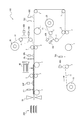
- Example of a manufacturing device for a laminated body for a secondary battery The production of the secondary battery laminate using the inspection method of the present invention and the method for producing the secondary battery laminate of the present invention is not particularly limited, and the manufacturing apparatus as shown in FIG. 1, for example. It can be done using 100.
- the manufacturing apparatus 100 shown in FIG. 1 is a laminated body for a secondary battery in which electrodes (positive electrode and negative electrode) and separators are laminated in the order of “positive electrode / separator / negative electrode / separator” from the upper side to the lower side. It is an apparatus for manufacturing 200.
- the obtained laminated body 200 for a secondary battery is cut into an appropriate size and then further laminated before being used in the manufacture of a secondary battery.
- the manufacturing apparatus 100 is previously cut into a negative electrode roll 10 in which the negative electrode 11 is wound in a roll shape, and a first separator roll 20 and a second separator roll 30 in which the separators 21 and 31 are wound in a roll shape. It is provided with a positive electrode stocker 40 for accommodating the positive electrode 41. Further, the manufacturing apparatus 100 includes a plurality of transfer rollers 1 (11 in the illustrated example), a plurality of press rollers 2 (3 sets in the illustrated example), and a plurality of coating machines 60A (6 in the illustrated example). It further includes 60B, 60C, 60D, 60E, 60F, a plurality of laser displacement meters 70A, 70B, 70C, 70D, 70E, 70F (six in the illustrated example), and a cutting machine 50.
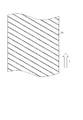
- a coating pattern having a diagonal stripe shape as shown in FIG. 2 is formed on the bonded surface of the negative electrode 11 that is fed out from the negative electrode roll 10 and conveyed via the transfer roller 1.
- the paint 61 is supplied from the coating machine 60A (coating step).
- the displacement of the bonded surface of the negative electrode 11 coated with the paint 61 is measured by a laser displacement meter 70A, and the number of poorly coated portions on the bonded surface is specified (inspection step). For example, when the number of poorly applied parts exceeds a predetermined reference value, it is possible to take prompt action such as immediately stopping the production line to solve the problem (hereinafter, the same applies to the "inspection process").
- the negative electrode 11 that has been inspected by the laser displacement meter 70A is heated by the heat roller using the transfer roller 1 located between the laser displacement meter 70A and the press roller 2 as a heat roller.
- the coating material 61 is dried by this heating, and an adhesive material is formed on the bonded surface of the negative electrode 11 (drying step).
- the negative electrode 11 on which the adhesive material is formed and the separator 21 unwound from the first separator roll 20 are bonded by the press roller 2 (bonding step).
- the negative electrode 11 and the separator 21 need only have an adhesive material formed on at least one of the bonded surfaces. That is, the adhesive material may be formed only on the bonded surface of the negative electrode 11 as described above, the adhesive material may be formed only on the bonded surface of the separator 21, or both the negative electrode 11 and the separator 21 may be formed. An adhesive material may be formed on the bonded surface.
- the adhesive material is formed on the bonding surface of the separator 21, it is oblique to the bonding surface of the separator 21 conveyed from the first separator roll 20 via the transfer roller 1, for example, as shown in FIG.
- the paint 61 is applied from the coating machine 60B so as to have a striped coating pattern (coating step), and the displacement of the bonding surface of the separator 21 coated with the paint 61 is measured by a laser displacement meter 70B.
- the number of coating defects on the bonded surface is specified (inspection process), and the transport roller 1 located between the laser displacement meter 70B and the press roller 2 is used as a heat roller and heated by the heat roller to separate the separator.
- An adhesive material is formed on the bonded surface of 21 (drying step).
- the paint 61 is supplied from the coating machine 60C.
- the displacement of the bonded surface of the negative electrode 11 coated with the paint 61 is measured by the laser displacement meter 70C, and the number of poorly coated portions on the bonded surface is specified (inspection step).
- the laminate that has been inspected by the laser displacement meter 70C is heated by the heat roller using the transfer roller 1 located between the laser displacement meter 70C and the press roller 2 as a heat roller.
- the coating material 61 is dried by this heating, and an adhesive material is formed on the bonded surface of the negative electrode 11 in the laminate (drying step). Then, the laminate including the negative electrode 11 on which the adhesive material is formed and the separator 31 unwound from the second separator roll 30 are bonded by the press roller 2 (bonding step).
- the negative electrode 11 and the separator 31 constituting the laminate have an adhesive material formed on at least one of the bonded surfaces. That is, the adhesive material may be formed only on the bonded surface of the negative electrode 11 as described above, the adhesive material may be formed only on the bonded surface of the separator 31, or both the negative electrode 11 and the separator 31 may be formed. An adhesive material may be formed on the bonded surface.
- the adhesive material is formed on the bonding surface of the separator 31, it is oblique to the bonding surface of the separator 31 conveyed from the second separator roll 30 via the transfer roller 1, for example, as shown in FIG.
- the paint 61 is supplied from the coating machine 60D so as to have a striped coating pattern (coating step), and the displacement of the bonding surface of the separator 31 coated with the paint 61 is measured by a laser displacement meter 70D.
- the number of coating defects on the bonded surface is specified (inspection process), and the transport roller 1 located between the laser displacement meter 70D and the press roller 2 is used as a heat roller and heated by the heat roller to separate the separator.
- An adhesive material is formed on the bonded surface of 31 (drying step).
- the surface of the laminate of the negative electrode 11 and the separators 21 and 31 bonded together using an adhesive material on the separator 31 side is coated with an oblique stripe shape similar to that shown in FIG. 2, for example.
- the paint 61 is supplied from the coating machine 60E so as to form a pattern.
- the displacement of the bonded surface of the separator 31 coated with the paint 61 is measured by the laser displacement meter 70E, and the number of poorly coated portions on the bonded surface is specified (inspection step).
- the laminate that has been inspected by the laser displacement meter 70E is heated by the heat roller using the transfer roller 1 located between the laser displacement meter 70E and the press roller 2 as a heat roller.
- the coating material 61 is dried by this heating, and an adhesive material is formed on the bonded surface on the separator 31 in the laminate (drying step). Then, the laminate provided with the separator 31 on which the adhesive material is formed and the positive electrode 41 supplied from the positive electrode stocker 40 are bonded by the press roller 2 (bonding step).
- the manufacturing apparatus 100 with respect to the surface on the positive electrode side of the laminated body 200 for a secondary battery, which is laminated in the order of "positive electrode / separator / negative electrode / separator" from the upper side to the lower side, for example, FIG.
- the transfer roller 1 After supplying the paint 61 from the coating machine 60F and inspecting it with the laser displacement meter 70F so that the coating pattern has a diagonal stripe shape similar to the one shown, the transfer roller 1 is used as a heat roller as needed.
- the laminated body 200 for the secondary battery is cut by the cutting machine 50.
- the laminated body (cut piece) obtained by cutting the laminated body 200 for a secondary battery with a cutting machine 50 is used for manufacturing a secondary battery after being further laminated.
- the method for manufacturing a secondary battery of the present invention includes a step of manufacturing a laminate for a secondary battery using the method for producing a laminate for a secondary battery of the present invention described above, a laminate for a secondary battery, and an electrolytic solution. Includes the process of assembling the secondary battery using and (assembly process).
- the rate of occurrence of poor bonding between the electrodes and the separator is reduced when the laminated body is manufactured, so that a secondary battery having excellent battery characteristics can be efficiently manufactured. ..
- the electrolytic solution an organic electrolytic solution in which a supporting electrolyte is dissolved in an organic solvent is usually used.
- a lithium salt is used as the supporting electrolyte.
- lithium salts include LiPF 6 , LiAsF 6 , LiBF 4 , LiSbF 6 , LiAlCl 4 , LiClO 4 , CF 3 SO 3 Li, C 4 F 9 SO 3 Li, CF 3 COOLi, (CF 3 CO) 2 NLi. , (CF 3 SO 2 ) 2 NLi, (C 2 F 5 SO 2 ) NLi and the like.
- LiPF 6 , LiClO 4 , CF 3 SO 3 Li are preferable, and LiPF 6 is particularly preferable because they are easily dissolved in a solvent and show a high degree of dissociation.
- One type of electrolyte may be used alone, or two or more types may be used in combination at an arbitrary ratio. Normally, the more the supporting electrolyte with a higher degree of dissociation is used, the higher the lithium ion conductivity tends to be. Therefore, the lithium ion conductivity can be adjusted depending on the type of the supporting electrolyte.
- the organic solvent used in the electrolytic solution is not particularly limited as long as it can dissolve the supporting electrolyte, and for example, dimethyl carbonate (DMC), ethylene carbonate (EC), diethyl carbonate (DEC), and propylene carbonate (PC). ), Butylene carbonate (BC), ethyl methyl carbonate (EMC), vinylene carbonate (VC) and other carbonates; esters such as ⁇ -butyrolactone and methyl formate; ethers such as 1,2-dimethoxyethane and tetrahydrofuran; , Sulfur-containing compounds such as dimethyl sulfoxide; and the like are preferably used. Further, a mixed solution of these solvents may be used.
- the dielectric constant is high and the stable potential region is wide.
- the lower the viscosity of the solvent used the higher the lithium ion conductivity tends to be. Therefore, the lithium ion conductivity can be adjusted depending on the type of solvent.
- the concentration of the electrolyte in the electrolytic solution can be adjusted as appropriate. Further, a known additive may be added to the electrolytic solution.
- additional battery members are further laminated as necessary on the secondary battery laminate manufactured according to the method for manufacturing the secondary battery laminate of the present invention.
- the obtained laminate can be assembled by winding or folding it according to the shape of the battery, putting it in a battery container, injecting an electrolytic solution into the battery container, and sealing the battery container.
- overcurrent prevention elements such as fuses and PTC elements, expanded metal, lead plates, etc. may be provided as necessary. ..
- the shape of the secondary battery may be, for example, a coin type, a button type, a sheet type, a cylindrical type, a square type, a flat type, or the like.
- Example 1 Preparation of the first binder> 100 parts of ion-exchanged water and 0.3 part of ammonium persulfate were supplied to a reactor equipped with a stirrer, the gas phase part was replaced with nitrogen gas, and the temperature was raised to 80 ° C. On the other hand, in another container, 40 parts of ion-exchanged water, 0.2 parts of sodium dodecylbenzenesulfonate as an emulsifier, 40.3 parts of styrene as an aromatic monovinyl monomer, and as a monofunctional (meth) acrylic acid ester monomer.
- a monomer composition for forming a shell portion containing 29.7 parts of styrene as an aromatic monovinyl monomer and 0.3 parts of methacrylic acid as an acidic group-containing monomer was added to this aqueous dispersion for 60 minutes. It was continuously supplied over a period of time, and the polymerization was continued.
- An aqueous dispersion of the first binder (particulate polymer having a core-shell structure, volume average particle size: 0.7 ⁇ m) by cooling when the polymerization conversion rate reaches 98% and stopping the reaction. was prepared.
- Neoperex G15 manufactured by Kao Chemical Co., Ltd.
- aqueous dispersion of the second binder (particulate polymer having no core-shell structure, volume average particle diameter: 0.2 ⁇ m) was prepared.
- Propylene glycol was further added to the obtained mixture to adjust the solid content concentration to 10% to obtain a coating material.
- a polypropylene (PP) separator product name “Cellguard 2500”, surface roughness Sa: 0.1 ⁇ m
- Inkjet head of an inkjet coating machine manufactured by Konica, "KM1024 (shear mode type)
- the coating was performed so that the dot-shaped paint (diameter: 5 ⁇ m) formed a pattern in which the dot-shaped paints (diameter: 5 ⁇ m) were arranged at a distance of 500 ⁇ m between the centers. Then, while transporting the separator, the displacement of the surface (bonded surface) coated with the paint is measured with a laser displacement meter (“LJ-V7060” manufactured by KEYENCE CORPORATION), and the coating defective portion (the above desired) for 10 m of the separator is measured. The number of places where the dot-shaped paint is not placed) was specified based on the pattern of. The average height of the paint from the bonded surface was calculated from the measurement results by the laser displacement meter. The results are shown in Table 1.
- the paint on the separator was dried by using a heat roller as a part of the transport roller (drying temperature: 70 ° C., drying time: 1 second) to form an adhesive material on the separator.
- the average diameter of the dot-shaped adhesive material was calculated from the measurement results by a laser microscope (“VR-3100” manufactured by KEYENCE CORPORATION). The results are shown in Table 1. ⁇ Evaluation of specific accuracy of defective coating> 100 m of the separator having an adhesive material formed on one surface was collected. The surface of the collected separator on which the adhesive material was formed was observed with a laser microscope (“VR-3100” manufactured by KEYENCE CORPORATION), and the number of poorly applied parts for 100 m of the separator was specified.
- Examples 2 to 4 A paint and a separator were prepared in the same manner as in Example 1. Then, with respect to the dot-shaped paint applied on the separator, the procedure was the same as that of Example 1 except that the diameters were changed to 40 ⁇ m (Example 2), 100 ⁇ m (Example 3), and 250 ⁇ m (Example 4), respectively. Coating, inspection and drying were performed, and the accuracy of identifying defective coating areas was evaluated. The results are shown in Table 1.
- Example 5 to 8 A paint was prepared in the same manner as in Example 1. Then, coating, inspection, and drying were performed in the same procedure as in Examples 1 to 4 except that the negative electrode prepared as described below was used instead of the separator, and the identification accuracy of the coating defective portion was evaluated. .. The results are shown in Table 1. The coating was applied to the surface of the negative electrode mixture layer of the negative electrode.
- a 5% aqueous sodium hydroxide solution was added to the mixture containing the binder for the negative electrode mixture layer to adjust the pH to 8, and then unreacted monomers were removed by hot vacuum distillation. Then, the temperature was cooled to 30 ° C. or lower to obtain an aqueous dispersion containing a desired binder for the negative electrode mixture layer.
- 100 parts of artificial graphite (volume average particle size: 15.6 ⁇ m) as a negative electrode active material and a 2% aqueous solution of carboxymethyl cellulose sodium salt (manufactured by Nippon Paper Industries, Inc., product name “MAC350HC”) as a viscosity modifier are solidified.
- the mixture was further mixed at a temperature of 25 ° C. for 60 minutes. Further, after adjusting the solid content concentration to 62% with ion-exchanged water, the mixture was further mixed at a temperature of 25 ° C. for 15 minutes. To the obtained mixed liquid, 1.5 parts of an aqueous dispersion containing the above-mentioned binder for the negative electrode mixture layer and ion-exchanged water are added so that the final solid content concentration becomes 52%. It was adjusted and mixed for an additional 10 minutes. This was defoamed under reduced pressure to obtain a slurry composition for a negative electrode of a secondary battery having good fluidity.
- the obtained slurry composition for the negative electrode of the secondary battery is applied on both sides of a copper foil having a thickness of 20 ⁇ m, which is a current collector, with a comma coater so that the film thickness after drying is about 150 ⁇ m, and dried. rice field.
- This drying was carried out by transporting the copper foil at a rate of 0.5 m / min in an oven at a temperature of 60 ° C. over 2 minutes. Then, it was heat-treated at a temperature of 120 degreeC for 2 minutes, and the negative electrode raw fabric before pressing was obtained.
- the negative electrode raw material before pressing was rolled by a roll press to obtain a negative electrode (thickness of the negative electrode mixture layer: 80 ⁇ m, surface roughness Sa of the negative electrode mixture layer: 0.3 ⁇ m).
- Example 9 A paint and a separator were prepared in the same manner as in Example 1. Then, instead of the inkjet coating machine, the paint was applied onto the separator using a gravure printing machine and a gravure roll having a gravure plate having a desired dot shape. The diameters of the dots were set to 20 ⁇ m (Example 9), 40 ⁇ m (Example 10), 100 ⁇ m (Example 11), and 250 ⁇ m (Example 12). The inspection and drying were carried out in the same procedure as in Example 1, and the accuracy of identifying the poorly applied portion was evaluated. The results are shown in Table 1.
- Comparative Examples 9 to 12 In the inspection, the same procedure as in Comparative Examples 1 to 4 was carried out except that a CCD camera was used instead of the laser displacement meter as the inspection device, and the accuracy of identifying the defective coating portion was evaluated. The results are shown in Table 1.
- the inspection method of the present invention when manufacturing a laminate for a secondary battery in which battery members are bonded to each other via an adhesive material, it is possible to identify a poorly applied portion with high accuracy. Further, according to the method for manufacturing a laminated body for a secondary battery of the present invention, it is possible to efficiently manufacture a laminated body for a secondary battery by reducing the occurrence rate of poor bonding between the electrode and the separator. Then, according to the method for manufacturing a secondary battery of the present invention, a secondary battery having excellent battery characteristics can be efficiently manufactured.
Landscapes
- Chemical & Material Sciences (AREA)
- Chemical Kinetics & Catalysis (AREA)
- Electrochemistry (AREA)
- General Chemical & Material Sciences (AREA)
- Engineering & Computer Science (AREA)
- Manufacturing & Machinery (AREA)
- Materials Engineering (AREA)
- Physics & Mathematics (AREA)
- General Physics & Mathematics (AREA)
- Secondary Cells (AREA)
- Battery Electrode And Active Subsutance (AREA)
Abstract
Description
しかしながら、上記従来の検査方法には、塗布不良箇所を一層高い精度で特定することが求められていた。特に近年、二次電池の内部抵抗を低くして電池特性を高めるために、抵抗成分となり得る接着材料の形成量低減が試みられている。しかしながら、接着材料の形成量を低減すべく塗料の使用量を低減すると、乾燥後に形成される接着材料が貼り合わせ面の凹凸に埋もれてしまう等の理由により、上記従来の検査方法では塗布不良箇所の特定が困難であることが、本発明者の検討により明らかとなった。
乾燥前の塗料は、乾燥後に形成される接着材料に比して、乾燥で除去される溶媒の分貼り合わせ面からの変位(高さ)が大きくなり易い。そのため、塗料を塗布した貼り合わせ面について、乾燥前にレーザー変位計によりその変位を測定することで、塗布箇所と塗布不良箇所の変位の差が明確となり塗布不良箇所を高い精度で特定することができる。即ち、このような検査を実施すれば、仮に塗布不良箇所が多量に発生した場合は、生産ラインを即座に停止させ、塗布不良箇所が生じた原因(塗布ノズルの詰まり等)を究明し、当該原因を取り除くといった迅速な対応が可能となる。結果として、電極とセパレータの貼り合わせ不良の発生割合を低減することができる。
なお、本発明において、塗料の「貼り合わせ面からの塗料の平均高さ」は、レーザー変位計等により測定した任意の1000点の塗料の高さの平均値として算出することができる。
なお、本発明において、「ドット状に形成された接着材料の平均径」は、レーザー顕微鏡等による観察で得られた、貼り合わせ面の平面視画像における任意の1000個のドットの最大径(1つのドットの外縁上の2点を結ぶ線分の長さのうち、最大の長さ)の平均値として算出することができる。
また、本発明の二次電池用積層体の製造方法によれば、電極とセパレータの貼り合わせ不良の発生割合を低減して、二次電池用積層体を効率良く製造することができる。
そして、本発明の二次電池の製造方法によれば、電池特性に優れる二次電池を効率良く製造することができる。
ここで、本発明の検査方法は、電極(正極及び/又は負極)と、セパレータとを貼り合わせて二次電池用積層体を製造するに際し、電極及び/又はセパレータの貼り合わせ面における塗布不良箇所を特定するために用いることができる。
また、本発明の二次電池用積層体の製造方法は、上述した本発明の検査方法に従う検査を経て二次電池用積層体を製造する方法であり、二次電池用積層体を連続的に製造する際に特に好適に用いることができる。
そして、本発明の二次電池の製造方法は、上述した本発明の二次電池用積層体の製造方法に従い作製した二次電池用積層体を用い、非水系二次電池(例えば、リチウムイオン二次電池)などの二次電池を製造する際に用いることができる。
本発明の検査方法は、上述した通り、二次電池用積層体を製造する過程において使用する。具体的に、本発明の検査方法を実施する二次電池用積層体の製造過程は、少なくとも、
電極とセパレータの少なくとも一方の貼り合わせ面に、結着材及び溶媒を含む塗料を塗布する工程(塗布工程)と、
上記塗布工程後、塗料が塗布された貼り合わせ面の変位をレーザー変位計により測定して、塗布不良箇所を特定する工程(検査工程)と、
上記検査工程後、貼り合わせ面に塗布された塗料を乾燥して接着材料を形成する工程(乾燥工程)と、
上記乾燥工程後、接着材料が形成された貼り合わせ面を介して、電極とセパレータとを貼り合わる工程(貼り合わせ工程)と、
を備える。
更に、このような製造過程によれば、塗布工程、検査工程、乾燥工程、及び貼り合わせ工程を一つのラインで実施するインライン生産により積層体を製造することが可能となる。そのため、従来の製造過程において、電池部材の移送のため行っていた捲回・スリットにより生じる接着材料の脱落やブロッキングといった問題が生じることもない。
積層体は、電極とセパレータとが貼り合わせ面を介して貼り合わされたものである。ここで、セパレータと貼り合わされて積層体を構成する電極は、正極のみであってもよいし、負極のみであってもよいし、正極及び負極の双方であってもよい。また、正極及び負極の双方をセパレータと貼り合わせて積層体とする場合、積層体が有する正極、負極及びセパレータの数は、それぞれ、1つであってもよいし、2つ以上であってもよい。
即ち、積層体の構造は、下記(1)~(6)の何れであってもよい。
(1)正極/セパレータ
(2)負極/セパレータ
(3)正極/セパレータ/負極
(4)正極/セパレータ/負極/セパレータ
(5)セパレータ/正極/セパレータ/負極
(6)複数の正極及び負極がセパレータを介して交互に積層された構造(例えば、「セパレータ/負極/セパレータ/正極/セパレータ/負極・・・・・/セパレータ/正極」など)
なお、複数の電極及び/又はセパレータを有する積層体は、例えば、上述した塗布工程、検査工程、乾燥工程、及び貼り合わせ工程を繰り返し実施することにより製造することができる。
ここで、電極としては、特に限定されることなく、例えば、集電体の片面又は両面に電極合材層を形成してなる電極基材からなる電極、或いは、電極基材の電極合材層上に多孔膜層を更に形成してなる電極を用いることができる。
なお、集電体、電極合材層及び多孔膜層としては、特に限定されることなく、例えば特開2013-145763号公報に記載のもの等、二次電池の分野において使用され得る任意の集電体、電極合材層及び多孔膜層を使用し得る。ここで、多孔膜層とは、例えば特開2013-145763号公報に記載されているような非導電性粒子を含む層を指す。
そして、積層体の製造に用いられる電極は、ロール状に巻かれていてもよいし、予め切断されていてもよい。
また、電極の厚みは、特に限定されないが、30μm以上250μm以下であることが好ましい。
また、セパレータとしては、特に限定されることなく、例えば、セパレータ基材からなるセパレータ、又は、セパレータ基材の片面又は両面に多孔膜層を形成してなるセパレータを用いることができる。
なお、セパレータ基材及び多孔膜層としては、特に限定されることなく、例えば特開2012-204303号公報や特開2013-145763号公報に記載のもの等、二次電池の分野において使用され得る任意のセパレータ基材及び多孔膜層を使用し得る。
そして、積層体の製造に用いられるセパレータは、ロール状に巻かれていてもよいし、予め切断されていてもよい。中でも、積層体を効率良く連続的に製造する観点からは、セパレータとしては、ロール状に巻かれているものを用いることが好ましい。
ここで、セパレータの厚みは、特に限定されないが、1μm以上30μm以下であることが好ましい。
塗布工程では、電極及び/又はセパレータの貼り合わせ面に、塗料を塗布する。
塗料は、貼り合わせ面上で乾燥されることにより接着材料を形成し得る成分である。そして、塗料は、結着材及び溶媒を含み、任意に、非導電性粒子などの結着材及び溶媒以外の成分を含む。
結着材としては、電極とセパレータとを接着可能であり、且つ、電池反応を阻害しないものであれば、特に限定されることなく、二次電池の分野において使用されている任意の結着材を用いることができる。中でも、電極とセパレータとを良好に接着させる観点からは、結着材としては、重合体からなる結着材を用いることが好ましい。なお、結着材を構成する重合体は、1種類のみであってもよいし、2種類以上であってもよい。
なお、本発明において、「(メタ)アクリル酸」とは、アクリル酸及び/又はメタクリル酸を意味する。
なお、重合体よりなる結着材が粒子状である場合、当該粒子状の結着材は、単一の重合体から形成された単一相構造の粒子であってもよいし、互いに異なる2つ以上の重合体が物理的又は化学的に結合して形成された異相構造の粒子であってもよい。ここで、異相構造の具体例としては、球状の粒子であって中心部(コア部)と外殻部(シェル部)とが異なる重合体から形成されているコアシェル構造;2つ以上の重合体が並置された構造であるサイドバイサイド構造;などが挙げられる。なお、本発明において、「コアシェル構造」には、コア部の外表面をシェル部が完全に覆う構造の他、コア部の外表面をシェル部が部分的に覆う構造も含まれるものとする。そして、本発明では、外観上、コア部の外表面がシェル部によって完全に覆われているように見える場合であっても、シェル部の内外を連通する孔が形成されていれば、そのシェル部はコア部の外表面を部分的に覆うシェル部とする。
なお、本発明において、「体積平均粒子径」とは、レーザー回折法で測定された体積基準の粒子径分布において、小径側から計算した累積体積が50%となる粒子径を表す。
更に、粒子状の結着材がコアシェル構造を有する重合体を含む場合、当該コアシェル構造を有する重合体の体積平均粒子径は、0.1μm以上であることが好ましく、0.15μm以上であることがより好ましく、0.2μm以上であることが更に好ましく、8μm以下であることが好ましく、6μm以下であることがより好ましく、4μm以下であることが更に好ましい。コアシェル構造を有する重合体よりなる結着材の体積平均粒子径が0.1μm以上であれば、電極とセパレータとの接着力を高めることができる。また、コアシェル構造を有する重合体よりなる結着材の体積平均粒子径が8μm以下であれば、積層体を用いて作製した二次電池のエネルギー密度を高めることができる。
ここで、本発明において、ガラス転移温度は、示差熱分析測定装置を用いた下記の手順で測定することができる。
まず、示差熱分析測定装置(エスアイアイ・ナノテクノロジー社製、製品名「EXSTAR DSC6220」)を用い、乾燥させた測定試料としての重合体10mgをアルミパンに計量し、リファレンスとして空のアルミパンを用い、測定温度範囲-120℃~200℃の間で、昇温速度10℃/分、常温常湿下で、DSC曲線を測定する。この昇温過程で、微分信号(DDSC)が0.05mW/分/mg以上となるDSC曲線の吸熱ピークが出る直前のベースラインと、吸熱ピーク後に最初に現れる変曲点でのDSC曲線の接線との交点として、ガラス転移温度を求めることができる。
なお、重合体が後述のコアシェル構造を有しており、測定試料として、コア部の重合体又はシェル部の重合体を用いる場合、コア部の重合体及びシェル部の重合体については、各重合体の調製に使用した単量体組成物を使用し、当該重合体の重合条件と同様の重合条件で、測定試料となる重合体を含む水分散液をそれぞれ作製し、当該水分散液を乾燥させることで測定試料としての重合体を得ることができる。
そして、コアシェル構造を有する重合体のコア部のガラス転移温度は、-40℃以上200℃以下であることが好ましく、-40℃以上100℃以下であることがより好ましく、-40℃以上70℃以下であることが更に好ましい。コア部のガラス転移温度が-40℃以上であれば、接着材料を介して電池部材同士を更に強固に接着させることができる。また、コア部のガラス転移温度が100℃以下であれば、粒子状重合体の重合安定性を確保することができる。
また、コアシェル構造を有する重合体のシェル部のガラス転移温度は、10℃以上であることが好ましく、20℃以上であることがより好ましく、30℃以上であることが更に好ましく、130℃以下であることが好ましく、120℃以下であることがより好ましい。シェル部のガラス転移温度が10℃以上であれば、貼り合わせ面に供給された後も粒子形状を良好に保つことができる。また、シェル部のガラス転移温度が130℃以下であれば、電極とセパレータとを良好に接着することができる。
ここで、コアシェル構造を有する重合体は、25℃以下に少なくとも一つのガラス転移温度を有することが好ましい。
溶媒としては、特に限定されることなく、例えば、水、有機溶媒及びそれらの混合物を用いることができる。なお、有機溶媒としては、特に限定されることなく、シクロペンタン、シクロヘキサン等の環状脂肪族炭化水素類;トルエン、キシレン等の芳香族炭化水素類;エチルメチルケトン、シクロヘキサノン等のケトン類;酢酸エチル、酢酸ブチル、γ-ブチロラクトン、ε-カプロラクトン等のエステル類;アセトニトリル、プロピオニトリル等のニトリル類;テトラヒドロフラン、エチレングリコールジエチルエーテル等のエーテル類:メタノール、エタノール、イソプロパノール、エチレングリコール、エチレングリコールモノメチルエーテル等のアルコール類;などが挙げられる。
上述した中でも、積層体を効率的に製造する観点からは、溶媒としては、水及びアルコールが好ましく、水がより好ましい。
塗料が任意に含有し得る非導電性粒子は、塗料の溶媒及び二次電池の電解液に溶解せず、それらの中においても、その形状が維持される粒子である。上述した結着材及び溶媒に加え、非導電性粒子を含有する塗料を用いれば、乾燥後に形成される接着材料に非導電性粒子を包含させることができる。このような非導電性粒子は、積層体の耐熱収縮性の向上や、二次電池内における短絡の防止に寄与し得る。
具体的には、非導電性粒子としては、無機微粒子と、上述した結着材以外の重合体からなる有機微粒子との双方を用いることができるが、通常は無機微粒子が用いられる。なかでも、非導電性粒子の材料としては、二次電池の使用環境下で安定に存在し、電気化学的に安定である材料が好ましい。このような観点から非導電性粒子の好ましい例を挙げると、酸化アルミニウム(アルミナ)、酸化アルミニウムの水和物(ベーマイト(AlOOH)、ギブサイト(Al(OH)3)、酸化ケイ素、酸化マグネシウム(マグネシア)、酸化カルシウム、酸化チタン(チタニア)、チタン酸バリウム(BaTiO3)、ZrO、アルミナ-シリカ複合酸化物等の酸化物粒子;窒化アルミニウム、窒化ホウ素等の窒化物粒子;シリコン、ダイヤモンド等の共有結合性結晶粒子;硫酸バリウム、フッ化カルシウム、フッ化バリウム等の難溶性イオン結晶粒子;タルク、モンモリロナイト等の粘土微粒子;などが挙げられる。また、これらの粒子は、必要に応じて元素置換、表面処理、固溶体化等が施されていてもよい。これらの中でも、非導電性粒子としては、硫酸バリウム粒子、アルミナ粒子が好ましい。
なお、上述した非導電性粒子は、1種類を単独で使用してもよいし、2種類以上を組み合わせて用いてもよい。
塗料は、固形分濃度が、50質量%以下であることが好ましく、40質量%以下であることがより好ましく、20質量%以下であることが更に好ましく、15質量%以下であることが一層好ましく、10質量%以下であることが特に好ましい。固形分濃度が50質量%以下であれば、貼り合わせ面において塗料が十分な平均高さを有することが可能となり、レーザー変位計よる検出が容易となる。そして更に、固形分濃度が20質量%以下の塗料は、粘度が過度に高まることもなく取り扱い性に優れる。そのため塗布不良箇所の発生を十分に抑制して、電極とセパレータの貼り合わせ不良の発生割合を低減することができる。
なお、塗料の固形分濃度の下限値は特に限定されないが、乾燥効率を確保する観点から、固形分濃度は、1質量%以上であることが好ましく、5質量%以上であることがより好ましい。
なお、本発明において、「粘度」とは、JIS Z8803に準拠して測定することができる。具体的には、「粘度」の値は、共軸二重円筒形回転粘度計を用いて測定された、温度25℃での粘度の値とすることができる。
そして、貼り合わせ面への塗料の塗布は、特に限定されることなく、例えば、インクジェット法、スプレー法、ディスペンサー法、グラビアコーティング法、スクリーン印刷法などの方法を用いて行うことができる。中でも、生産性及び形成形状の自由度の高さの観点からは、塗布方法は、インクジェット法であることが好ましい。
なお、本発明において、貼り合わせ面の「表面粗さSa」は、レーザー変位計顕微鏡(キーエンス製、型式:VK-X1000)を用いて貼り合わせ面上の任意の100μm四方の領域を10箇所測定して、算出することができる。
検査工程では、上記塗布工程において塗料が塗布された貼り合わせ面の変位を、レーザー変位計により測定して塗布不良箇所を特定する。
例えば、上述した塗布工程において、ドット状の塗料を所望のパターンとなるように貼り合わせ面に塗布した場合、当該所望のパターンと、レーザー変位計により測定された変位のデータから特定される実際に形成されたパターンとを比較することで、積層体を連続して(インラインで)製造する過程の途中で、塗布不良箇所の数などの特定を容易に行うことができる。
ここで、検査工程において塗布不良箇所が多量に発生し、例えば所定の基準値を超える場合には、生産ラインを即座に停止させて問題を解決するといった迅速な対応が可能となる。このような対応を即座に行うことができるため、結果として電極とセパレータの貼り合わせ不良の発生割合を低減することができる。
なお、レーザー変位計による測定条件(検査条件)は、貼り合わせ面を備える電池部材の材質、貼り合わせ面上の塗料の性状に応じて、適宜設定することができる。
乾燥工程では、上記検査工程後、貼り合わせ面上に塗布された塗料を乾燥して接着材料を形成する。
ここで、貼り合わせ面上の一箇所以上、好ましくは二箇所以上に接着材料を形成する場合、貼り合わせ面に形成する接着材料の形成面積は、一箇所当たり、15μm2以上であることが好ましく、25μm2以上であることがより好ましく、50μm2以上であることが更に好ましく、150000μm2以下であることが好ましく、100000μm2以下であることがより好ましく、80000μm2以下であることが更に好ましい。一箇所当たりの接着材料の形成面積が15μm2以上であれば、電極とセパレータとを十分に接着させることができる。また、一箇所当たりの接着材料の形成面積が150000μm2以下であれば、積層体を効率的に製造することができる。
なお、上記の形成面積は、塗料を貼り合わせ面に塗布する量、形状及び範囲を変更することで調整することができる。具体的には、形成面積は、例えば、接塗料をインクジェット法により貼り合わせ面に塗布する場合には、インクジェットヘッドのノズルからの塗料の吐出の諧調(同じポイントに吐出した回数)を変更することで調整することができる。
貼り合わせ工程では、上記乾燥工程後、接着材料が形成された貼り合わせ面を介して、電極とセパレータとを貼り合わる。ここで、貼り合わせは、特に限定されることなく、例えば、貼り合わせ面を介して重ね合わせた電極とセパレータとの積層体を加圧及び/又は加熱することにより行うことができる。
本発明の二次電池用積層体の製造方法は、電極と、セパレータとを貼り合わせてなる二次電池用積層体の製造方法であって、上述した本発明の検査方法に従って検査を行う工程を含む。
具体的には、本発明の二次電池用積層体の製造方法の一態様は、「検査方法」の項で上述した塗布工程、検査工程、乾燥工程、及び貼り合わせ工程を少なくとも含む。そして、本発明の二次電池用積層体の製造方法を用いれば、検査工程において塗布不良箇所を高い精度で特定することができ、仮に塗布不良箇所が多量に発生した場合は、生産ラインを即座に停止させて問題を解決するといった迅速な対応が可能となる。結果として、本発明の二次電池用積層体の製造方法を用いれば、電極とセパレータの貼り合わせ不良が発生する割合が低減して、効率良く二次電池用積層体を作製することができる。
そして、本発明の検査方法、及び本発明の二次電池用積層体の製造方法を用いた二次電池用積層体の製造は、特に限定されることなく、例えば図1に示すような製造装置100を用いて行うことができる。
なお、切断機50で二次電池用積層体200を切断して得られる積層体(切断片)は、更に重ね合わせてから二次電池の製造に用いられる。
本発明の二次電池の製造方法は、上述した本発明の二次電池用積層体の製造方法を用いて二次電池用積層体を製造する工程と、二次電池用積層体と、電解液とを用いて二次電池を組み立てる工程(組み立て工程)とを含む。
本発明の二次電池の製造方法を用いれば、積層体の作製に際して電極とセパレータの貼り合わせ不良の発生割合が低減されているため、電池特性に優れる二次電池を効率良く製造することができる。
ここで、電解液としては、通常、有機溶媒に支持電解質を溶解した有機電解液が用いられる。例えば、二次電池がリチウムイオン二次電池である場合には、支持電解質としては、リチウム塩が用いられる。リチウム塩としては、例えば、LiPF6、LiAsF6、LiBF4、LiSbF6、LiAlCl4、LiClO4、CF3SO3Li、C4F9SO3Li、CF3COOLi、(CF3CO)2NLi、(CF3SO2)2NLi、(C2F5SO2)NLiなどが挙げられる。なかでも、溶媒に溶けやすく高い解離度を示すので、LiPF6、LiClO4、CF3SO3Liが好ましく、LiPF6が特に好ましい。なお、電解質は1種類を単独で用いてもよく、2種類以上を任意の比率で組み合わせて用いてもよい。通常は、解離度の高い支持電解質を用いるほどリチウムイオン伝導度が高くなる傾向があるので、支持電解質の種類によりリチウムイオン伝導度を調節することができる。
なお、電解液中の電解質の濃度は適宜調整することができる。また、電解液には、既知の添加剤を添加してもよい。
<第一の結着材の調製>
撹拌機を備えた反応器に、イオン交換水100部、過硫酸アンモニウム0.3部を、それぞれ供給し、気相部を窒素ガスで置換し、温度80℃に昇温した。一方、別の容器で、イオン交換水40部、乳化剤としてドデシルベンゼンスルホン酸ナトリウム0.2部、芳香族モノビニル単量体としてスチレン40.3部、単官能(メタ)アクリル酸エステル単量体として2-エチルヘキシルアクリレート27.3部、酸性基含有単量体としてメタクリル酸2.1部、架橋性単量体としてのエチレングリコールジメタクリレート0.3部を混合して、コア部形成用単量体組成物を得た。このコア部形成用単量体組成物を3時間かけて前記反応器に連続的に添加して温度80℃で重合反応を行った。重合転化率が95%になるまで重合を継続させることにより、コア部を構成する粒子状の重合体を含む水分散液を得た。次いで、この水分散液に、芳香族モノビニル単量体としてのスチレン29.7部、及び酸性基含有単量体としてメタクリル酸0.3部を含むシェル部形成用単量体組成物を60分間かけて連続で供給し、重合を継続した。重合転化率が98%になった時点で冷却して反応を停止することにより、第一の結着材(コアシェル構造を有する粒子状重合体、体積平均粒子径:0.7μm)の水分散液を調製した。
<第二の結着材の調製>
撹拌機を備えた反応器に、イオン交換水90部、及び過流酸アンモニウム0.5部を、それぞれ供給し、気相部を窒素ガスで置換し、温度80℃に昇温した。一方、別の容器でイオン交換水15部、乳化剤としてネオぺレックスG15(花王ケミカル社製)1.0部、そして単官能(メタ)アクリル酸エステル単量体として2-エチルヘキシルアクリレート70.0部、芳香族モノビニル単量体としてスチレン25.0部、架橋性単量体としてアリルグリシジルエーテル1.7部及びアリルメタクリレート0.3部、並びに、酸性基含有単量体としてアクリル酸3.0部を混合して単量体組成物を得た。この単量体組成物を4時間かけて前記反応器に連続的に添加して重合を行った。連続添加中は、温度80℃で反応を行った。連続添加終了後、さらに温度80℃で3時間撹拌して反応を終了した。得られた水分散体を温度25℃に冷却後、これに水酸化ナトリウム水溶液を添加してpHを8.0に調整し、その後スチームを導入して未反応の単量体を除去し、第二の結着材(コアシェル構造を有しない粒子状重合体、体積平均粒子径:0.2μm)の水分散液を調製した。
<塗料の調製>
上記第一の結着材の水分散液と、上記第二の結着材の水分散液とを、固形分量の質量比が第一の結着材:第二の結着材=100:10になるように混合し、さらにイオン交換水を加えて、固形分濃度が10.5%になるように希釈した。得られた混合物に対して、プロピレングリコールを更に加えて固形分濃度が10%になるように調整して塗料を得た。
<セパレータの準備>
塗布体として、ポリプロピレン(PP)製のセパレータ(製品名「セルガード2500」、表面粗さSa:0.1μm)を準備した。
<塗布、検査、及び乾燥>
セパレータ原反から繰り出された上記セパレータを10m/分の速度で搬送しながら、セパレータの一方の表面に対し、インクジェット方式の塗工機(コニカ製、「KM1024(シアモードタイプ)」)のインクジェットヘッドから、上記塗料を塗布した。なお塗布は、ドット状の塗料(直径:5μm)が、中心間距離で500μm離れて配置されるパターンを形成するように行った。
そして、セパレータを搬送しながら、塗料を塗布した面(貼り合わせ面)の変位をレーザー変位計(キーエンス社製、「LJ-V7060」)により測定して、セパレータ10m分の塗布不良箇所(上記所望のパターンを基準として、ドット状の塗料が配置されていない箇所)の数を特定した。なお、貼り合わせ面からの塗料の平均高さを、上記レーザー変位計による測定結果から算出した。結果を表1に示す。
さらに上記検査後に、セパレータ上の塗料を、搬送ローラの一部にヒートローラを用いることで乾燥し(乾燥温度:70℃、乾燥時間:1秒)、セパレータ上に接着材料を形成した。ドット状の接着材料の平均径を、レーザー顕微鏡(キーエンス社製、「VR-3100」)による測定結果から算出した。結果を表1に示す。
<塗布不良箇所の特定精度評価>
一方の面に接着材料が形成された上記セパレータを100m採取した。採取したセパレータの接着材料形成面を、レーザー顕微鏡(キーエンス社製、「VR-3100」)で観察し、セパレータ100m分の塗布不良箇所の数を特定した。
そして、乾燥後にレーザー顕微鏡により特定した塗布不良箇所の数(N1)と、乾燥前にレーザー変位計により特定した塗布不良箇所の数(N2)の差、即ち塗布不良箇所の特定数の差(N1-N2)を算出し、下記の基準で評価した。結果を表1に示す。塗布不良箇所の特定数の差が小さいほど、搬送中のセパレータ表面の塗布不良箇所を、高い精度で特定可能であると言える。
A:塗布不良箇所の特定数の差が10個未満
B:塗布不良箇所の特定数の差が10個以上50個未満
C:塗布不良箇所の特定数の差が50個以上300個未満
D:塗布不良箇所の特定数の差が300個以上
実施例1と同様に塗料とセパレータを準備した。そして、セパレータ上に塗布するドット状の塗料について、直径をそれぞれ40μm(実施例2)、100μm(実施例3)、250μm(実施例4)に変更した以外は実施例1と同様の手順で、塗布、検査及び乾燥を行い、塗布不良箇所の特定精度を評価した。結果を表1に示す。
実施例1と同様に塗料を準備した。そして、セパレータに代えて下記のようにして調製した負極を塗布体とした以外は、実施例1~4と同様の手順で、塗布、検査及び乾燥を行い、塗布不良箇所の特定精度を評価した。結果を表1に示す。なお、塗布は負極の負極合材層表面に行った。
<負極の作製>
撹拌機付き5MPa耐圧容器に、1,3-ブタジエン33部、イタコン酸3.5部、スチレン63.5部、乳化剤としてドデシルベンゼンスルホン酸ナトリウム0.4部、イオン交換水150部及び重合開始剤としての過硫酸カリウム0.5部を入れ、十分に撹拌した後、温度50℃に加温して重合を開始した。重合転化率が96%になった時点で冷却して反応を停止し、負極合材層用結着材(SBR)を含む混合物を得た。上記負極合材層用結着材を含む混合物に、5%水酸化ナトリウム水溶液を添加して、pH8に調整後、加熱減圧蒸留によって未反応単量体の除去を行った。その後、温度30℃以下まで冷却し、所望の負極合材層用結着材を含む水分散液を得た。
次に、負極活物質としての人造黒鉛(体積平均粒子径:15.6μm)100部、粘度調整剤としてのカルボキシメチルセルロースナトリウム塩(日本製紙社製、製品名「MAC350HC」)の2%水溶液を固形分相当で1部、及びイオン交換水を混合して固形分濃度68%に調整した後、温度25℃で60分間さらに混合した。更に、イオン交換水で固形分濃度を62%に調整した後、温度25℃で15分間更に混合した。得られた混合液に、上記の負極合材層用結着材を含む水分散液を固形分相当で1.5部、及びイオン交換水を入れ、最終固形分濃度が52%となるように調整し、さらに10分間混合した。これを減圧下で脱泡処理して流動性の良い二次電池負極用スラリー組成物を得た。
得られた二次電池負極用スラリー組成物を、コンマコーターで、集電体である厚さ20μmの銅箔の両面上に、乾燥後の膜厚が150μm程度になるように塗布し、乾燥させた。この乾燥は、銅箔を0.5m/分の速度で温度60℃のオーブン内を2分間かけて搬送することにより行った。その後、温度120℃にて2分間加熱処理して、プレス前の負極原反を得た。このプレス前の負極原反をロールプレスで圧延して、負極(負極合材層の厚み:80μm、負極合材層の表面粗さSa:0.3μm)を得た。
実施例1と同様に塗料とセパレータを準備した。そして、インクジェット方式の塗工機に代えて、グラビア印刷機と所望のドット形状となるグラビア版目を有するグラビアロールを使用してセパレータ上に塗料を塗布した。ドットの直径は20μm(実施例9)、40μm(実施例10)、100μm(実施例11)、250μm(実施例12)となるようにした。検査及び乾燥を実施例1と同様の手順で行い、塗布不良箇所の特定精度を評価した。結果を表1に示す。
検査を乾燥の後に行った(即ち、「塗布不良箇所の数(N2)」を、乾燥前でなく乾燥後の貼り合わせ面をレーザー変位計で検査することにより特定した)以外は、それぞれ実施例1~8と同様に実施し、塗布不良箇所の特定精度を評価した。結果を表1に示す。
検査に際して、検査装置としてレーザー変位計に代えてCCDカメラを用いた以外は、比較例1~4と同様に実施し、塗布不良箇所の特定精度を評価した。結果を表1に示す。

一方、表1より、比較例1~12では、セパレータ又は電極上の塗布不良箇所を、高い精度では特定できないことが分かる。
また、本発明の二次電池用積層体の製造方法によれば、電極とセパレータの貼り合わせ不良の発生割合を低減して、二次電池用積層体を効率良く製造することができる。
そして、本発明の二次電池の製造方法によれば、電池特性に優れる二次電池を効率良く製造することができる。
2 プレスローラ
10 負極ロール
11 負極
20 第一セパレータロール
30 第二セパレータロール
21,31 セパレータ
40 正極ストッカー
41 正極
50 切断機
60A,60B,60C,60D,60E,60F 塗工機
61 塗料
70A,70B,70C,70D,70E レーザー変位計
100 製造装置
200 二次電池用積層体
T 搬送方向
Claims (7)
- 電極とセパレータの少なくとも一方の貼り合わせ面に、結着材及び溶媒を含む塗料を塗布する工程と、
前記貼り合わせ面に塗布された前記塗料を乾燥して接着材料を形成する工程とを経て、前記貼り合わせ面に前記接着材料を形成するに際し用いられる検査方法であって、
前記接着材料を形成する工程に先んじて、前記塗料が塗布された前記貼り合わせ面の変位をレーザー変位計により測定して、塗布不良箇所を特定する工程を備える、検査方法。 - 前記塗料を塗布する工程において、前記貼り合わせ面からの前記塗料の平均高さが2μm以上150μm以下である、請求項1に記載の検査方法。
- 前記接着材料を形成する工程において、前記接着材料がドット状に形成されており、前記ドット状に形成された前記接着材料の平均径が5μm以上300μm以下である、請求項1又は2に記載の検査方法。
- 前記塗料を塗布する工程において、前記塗料の固形分濃度が20質量%以下である、請求項1~3の何れかに記載の検査方法。
- 前記塗料を塗布する工程において、前記塗布をインクジェット法により行う、請求項1~4の何れかに記載の検査方法。
- 電極と、セパレータとを貼り合わせてなる二次電池用積層体の製造方法であって、
請求項1~5の何れかに記載の検査方法に従って検査を行う工程と、
前記検査を行った後に、前記接着材料が形成された前記貼り合わせ面を介して、前記電極と前記セパレータとを貼り合わる工程と、
を含む、二次電池用積層体の製造方法。 - 電極と、セパレータとを貼り合わせてなる二次電池用積層体を備える二次電池の製造方法であって、
請求項6に記載の二次電池用積層体の製造方法を用いて前記二次電池用積層体を製造する工程と、
前記二次電池用積層体と、電解液とを用いて二次電池を組み立てる工程とを備える、二次電池の製造方法。
Priority Applications (5)
| Application Number | Priority Date | Filing Date | Title |
|---|---|---|---|
| US17/904,481 US12567653B2 (en) | 2020-02-27 | 2021-02-17 | Inspection method, method of manufacturing secondary battery laminate, and method of manufacturing secondary battery |
| JP2022503297A JP7732448B2 (ja) | 2020-02-27 | 2021-02-17 | 検査方法、並びに二次電池用積層体の製造方法及び二次電池の製造方法 |
| EP21760054.3A EP4112189A4 (en) | 2020-02-27 | 2021-02-17 | TEST METHOD, PRODUCTION METHOD FOR LAMINATE FOR SECONDARY BATTERY, AND PRODUCTION METHOD FOR SECONDARY BATTERY |
| KR1020227028428A KR20220147590A (ko) | 2020-02-27 | 2021-02-17 | 검사 방법, 그리고 이차 전지용 적층체의 제조 방법 및 이차 전지의 제조 방법 |
| CN202180015006.4A CN115135422A (zh) | 2020-02-27 | 2021-02-17 | 检查方法、以及二次电池用层叠体的制造方法和二次电池的制造方法 |
Applications Claiming Priority (2)
| Application Number | Priority Date | Filing Date | Title |
|---|---|---|---|
| JP2020-032151 | 2020-02-27 | ||
| JP2020032151 | 2020-02-27 |
Publications (1)
| Publication Number | Publication Date |
|---|---|
| WO2021172143A1 true WO2021172143A1 (ja) | 2021-09-02 |
Family
ID=77490934
Family Applications (1)
| Application Number | Title | Priority Date | Filing Date |
|---|---|---|---|
| PCT/JP2021/006000 Ceased WO2021172143A1 (ja) | 2020-02-27 | 2021-02-17 | 検査方法、並びに二次電池用積層体の製造方法及び二次電池の製造方法 |
Country Status (6)
| Country | Link |
|---|---|
| US (1) | US12567653B2 (ja) |
| EP (1) | EP4112189A4 (ja) |
| JP (1) | JP7732448B2 (ja) |
| KR (1) | KR20220147590A (ja) |
| CN (1) | CN115135422A (ja) |
| WO (1) | WO2021172143A1 (ja) |
Cited By (3)
| Publication number | Priority date | Publication date | Assignee | Title |
|---|---|---|---|---|
| US20220299417A1 (en) * | 2021-03-16 | 2022-09-22 | Honda Motor Co., Ltd. | Porosity deriving method and porosity deriving device |
| JPWO2022209997A1 (ja) * | 2021-03-30 | 2022-10-06 | ||
| WO2024203927A1 (ja) * | 2023-03-31 | 2024-10-03 | 日本ゼオン株式会社 | 二次電池用積層体の製造方法 |
Families Citing this family (1)
| Publication number | Priority date | Publication date | Assignee | Title |
|---|---|---|---|---|
| CN115244745A (zh) * | 2020-03-25 | 2022-10-25 | 株式会社Lg新能源 | 制造单元电芯的设备和方法 |
Citations (9)
| Publication number | Priority date | Publication date | Assignee | Title |
|---|---|---|---|---|
| JP2011029084A (ja) * | 2009-07-28 | 2011-02-10 | Toyota Motor Corp | 検査装置 |
| WO2012132056A1 (ja) * | 2011-03-31 | 2012-10-04 | 大日本スクリーン製造株式会社 | 塗布装置および塗布膜形成システム |
| JP2012204303A (ja) | 2011-03-28 | 2012-10-22 | Nippon Zeon Co Ltd | 二次電池用電極、二次電池電極用バインダー、製造方法及び二次電池 |
| JP2012225848A (ja) * | 2011-04-21 | 2012-11-15 | Toyota Motor Corp | 膜厚分布測定装置および塗膜形成装置 |
| JP2013145763A (ja) | 2013-04-30 | 2013-07-25 | Nippon Zeon Co Ltd | 二次電池多孔膜用スラリー組成物、二次電池用電極、二次電池用セパレータおよび二次電池 |
| JP2016031812A (ja) * | 2014-07-28 | 2016-03-07 | 株式会社豊田自動織機 | 蓄電装置の製造方法および蓄電装置の製造装置 |
| JP2016046091A (ja) * | 2014-08-22 | 2016-04-04 | 株式会社Screenホールディングス | 塗工装置および塗工方法、並びに、膜・触媒層接合体の製造装置および製造方法 |
| JP2017168353A (ja) * | 2016-03-17 | 2017-09-21 | 株式会社Screenホールディングス | 塗膜検査装置、塗膜検査方法および膜・触媒層接合体の製造装置 |
| JP2020024861A (ja) * | 2018-08-08 | 2020-02-13 | 大野ロール株式会社 | レーザー変位計を用いた電極板伸び率測定装置とその方法 |
Family Cites Families (11)
| Publication number | Priority date | Publication date | Assignee | Title |
|---|---|---|---|---|
| JP5383471B2 (ja) | 2009-12-22 | 2014-01-08 | 三菱重工業株式会社 | 電極製造システム |
| WO2013047856A1 (ja) * | 2011-09-26 | 2013-04-04 | 住友化学株式会社 | 二次電池用接着樹脂組成物 |
| KR101369326B1 (ko) | 2011-12-27 | 2014-03-04 | 주식회사 엘지화학 | 세퍼레이터의 제조방법 및 이에 따라 제조된 세퍼레이터를 구비한 전기화학소자 |
| KR101185003B1 (ko) * | 2012-03-21 | 2012-10-02 | (주)대흥정밀산업 | 도막두께 측정장치 |
| US10490796B2 (en) * | 2014-02-19 | 2019-11-26 | Sion Power Corporation | Electrode protection using electrolyte-inhibiting ion conductor |
| JP6520938B2 (ja) * | 2014-06-27 | 2019-05-29 | 日本ゼオン株式会社 | 非水系二次電池機能層用組成物、非水系二次電池用機能層および非水系二次電池 |
| US10985355B2 (en) * | 2015-10-23 | 2021-04-20 | Sumitomo Chemical Company, Limited | Method for producing functional film, control device, and control method |
| US10734627B2 (en) | 2016-04-01 | 2020-08-04 | Lg Chen, Ltd. | Separator comprising an adhesion layer for an electrochemical device and an electrode assembly comprising the same |
| US12230765B2 (en) * | 2018-02-26 | 2025-02-18 | Zeon Corporation | Method of producing laminate for secondary battery |
| JP2018170281A (ja) | 2018-05-31 | 2018-11-01 | 旭化成株式会社 | 蓄電デバイス用セパレータ、蓄電デバイス及びリチウムイオン二次電池 |
| DE102020104668A1 (de) * | 2020-02-21 | 2021-08-26 | Volkswagen Aktiengesellschaft | Inspektionssystem für Batterieelektroden |
-
2021
- 2021-02-17 JP JP2022503297A patent/JP7732448B2/ja active Active
- 2021-02-17 CN CN202180015006.4A patent/CN115135422A/zh active Pending
- 2021-02-17 KR KR1020227028428A patent/KR20220147590A/ko active Pending
- 2021-02-17 EP EP21760054.3A patent/EP4112189A4/en active Pending
- 2021-02-17 WO PCT/JP2021/006000 patent/WO2021172143A1/ja not_active Ceased
- 2021-02-17 US US17/904,481 patent/US12567653B2/en active Active
Patent Citations (9)
| Publication number | Priority date | Publication date | Assignee | Title |
|---|---|---|---|---|
| JP2011029084A (ja) * | 2009-07-28 | 2011-02-10 | Toyota Motor Corp | 検査装置 |
| JP2012204303A (ja) | 2011-03-28 | 2012-10-22 | Nippon Zeon Co Ltd | 二次電池用電極、二次電池電極用バインダー、製造方法及び二次電池 |
| WO2012132056A1 (ja) * | 2011-03-31 | 2012-10-04 | 大日本スクリーン製造株式会社 | 塗布装置および塗布膜形成システム |
| JP2012225848A (ja) * | 2011-04-21 | 2012-11-15 | Toyota Motor Corp | 膜厚分布測定装置および塗膜形成装置 |
| JP2013145763A (ja) | 2013-04-30 | 2013-07-25 | Nippon Zeon Co Ltd | 二次電池多孔膜用スラリー組成物、二次電池用電極、二次電池用セパレータおよび二次電池 |
| JP2016031812A (ja) * | 2014-07-28 | 2016-03-07 | 株式会社豊田自動織機 | 蓄電装置の製造方法および蓄電装置の製造装置 |
| JP2016046091A (ja) * | 2014-08-22 | 2016-04-04 | 株式会社Screenホールディングス | 塗工装置および塗工方法、並びに、膜・触媒層接合体の製造装置および製造方法 |
| JP2017168353A (ja) * | 2016-03-17 | 2017-09-21 | 株式会社Screenホールディングス | 塗膜検査装置、塗膜検査方法および膜・触媒層接合体の製造装置 |
| JP2020024861A (ja) * | 2018-08-08 | 2020-02-13 | 大野ロール株式会社 | レーザー変位計を用いた電極板伸び率測定装置とその方法 |
Non-Patent Citations (1)
| Title |
|---|
| See also references of EP4112189A4 |
Cited By (4)
| Publication number | Priority date | Publication date | Assignee | Title |
|---|---|---|---|---|
| US20220299417A1 (en) * | 2021-03-16 | 2022-09-22 | Honda Motor Co., Ltd. | Porosity deriving method and porosity deriving device |
| US11796442B2 (en) * | 2021-03-16 | 2023-10-24 | Honda Motor Co., Ltd. | Porosity deriving method and porosity deriving device |
| JPWO2022209997A1 (ja) * | 2021-03-30 | 2022-10-06 | ||
| WO2024203927A1 (ja) * | 2023-03-31 | 2024-10-03 | 日本ゼオン株式会社 | 二次電池用積層体の製造方法 |
Also Published As
| Publication number | Publication date |
|---|---|
| JPWO2021172143A1 (ja) | 2021-09-02 |
| US12567653B2 (en) | 2026-03-03 |
| CN115135422A (zh) | 2022-09-30 |
| US20230097190A1 (en) | 2023-03-30 |
| KR20220147590A (ko) | 2022-11-03 |
| EP4112189A1 (en) | 2023-01-04 |
| EP4112189A4 (en) | 2024-07-24 |
| JP7732448B2 (ja) | 2025-09-02 |
Similar Documents
| Publication | Publication Date | Title |
|---|---|---|
| JP7732448B2 (ja) | 検査方法、並びに二次電池用積層体の製造方法及び二次電池の製造方法 | |
| JP7517146B2 (ja) | 二次電池用積層体の製造方法 | |
| JP7363777B2 (ja) | 非水系二次電池用スラリー、非水系二次電池用セパレータ、非水系二次電池用電極、非水系二次電池用積層体および非水系二次電池 | |
| CN113454838B (zh) | 非水系二次电池功能层用浆料组合物、非水系二次电池用间隔件以及非水系二次电池 | |
| CN112655106B (zh) | 二次电池及其制造方法 | |
| JP7259752B2 (ja) | 非水系二次電池用積層体およびその製造方法、非水系二次電池用捲回体、並びに非水系二次電池用電極の製造方法 | |
| WO2020054801A1 (ja) | 二次電池用積層体および二次電池、並びに、それらの製造方法 | |
| JP7268675B2 (ja) | 非水系二次電池用積層体の製造方法および非水系二次電池の製造方法 | |
| US20240322374A1 (en) | Laminate for non-aqueous secondary battery, composition for adhesion, and non-aqueous secondary battery | |
| JPWO2016031163A1 (ja) | 非水系二次電池用積層体および非水系二次電池部材の製造方法 | |
| CN114830397B (zh) | 二次电池及其制造方法 | |
| JP7652083B2 (ja) | 二次電池およびその製造方法 | |
| JP6891392B2 (ja) | 非水系二次電池用積層体 | |
| CN117223145A (zh) | 非水系二次电池黏合层用组合物、非水系二次电池用黏合层及其制造方法、非水系二次电池用层叠体及其制造方法、以及非水系二次电池 | |
| JP7707925B2 (ja) | 二次電池用積層体及び二次電池 | |
| US20240120617A1 (en) | Composition for non-aqueous secondary battery adhesive layer, adhesive layer for non-aqueous secondary battery and method for producing the same, laminate for non-aqueous secondary battery and method for producing the same, and non-aqueous secondary battery | |
| CN117642920A (zh) | 非水系二次电池黏合层用组合物、非水系二次电池用黏合层及其制造方法、非水系二次电池用层叠体及其制造方法、以及非水系二次电池 | |
| WO2024203927A1 (ja) | 二次電池用積層体の製造方法 | |
| CN117642879A (zh) | 非水系二次电池用层叠体、非水系二次电池用层叠体的制造方法以及非水系二次电池 |
Legal Events
| Date | Code | Title | Description |
|---|---|---|---|
| 121 | Ep: the epo has been informed by wipo that ep was designated in this application |
Ref document number: 21760054 Country of ref document: EP Kind code of ref document: A1 |
|
| ENP | Entry into the national phase |
Ref document number: 2022503297 Country of ref document: JP Kind code of ref document: A |
|
| NENP | Non-entry into the national phase |
Ref country code: DE |
|
| ENP | Entry into the national phase |
Ref document number: 2021760054 Country of ref document: EP Effective date: 20220927 |
|
| WWG | Wipo information: grant in national office |
Ref document number: 17904481 Country of ref document: US |