WO2021176637A1 - 空気調和機 - Google Patents
空気調和機 Download PDFInfo
- Publication number
- WO2021176637A1 WO2021176637A1 PCT/JP2020/009328 JP2020009328W WO2021176637A1 WO 2021176637 A1 WO2021176637 A1 WO 2021176637A1 JP 2020009328 W JP2020009328 W JP 2020009328W WO 2021176637 A1 WO2021176637 A1 WO 2021176637A1
- Authority
- WO
- WIPO (PCT)
- Prior art keywords
- indoor
- predetermined
- unit
- heat exchanger
- control unit
- Prior art date
- Legal status (The legal status is an assumption and is not a legal conclusion. Google has not performed a legal analysis and makes no representation as to the accuracy of the status listed.)
- Ceased
Links
Images





Classifications
-
- F—MECHANICAL ENGINEERING; LIGHTING; HEATING; WEAPONS; BLASTING
- F24—HEATING; RANGES; VENTILATING
- F24F—AIR-CONDITIONING; AIR-HUMIDIFICATION; VENTILATION; USE OF AIR CURRENTS FOR SCREENING
- F24F11/00—Control or safety arrangements
- F24F11/30—Control or safety arrangements for purposes related to the operation of the system, e.g. for safety or monitoring
- F24F11/41—Defrosting; Preventing freezing
- F24F11/43—Defrosting; Preventing freezing of indoor units
-
- F—MECHANICAL ENGINEERING; LIGHTING; HEATING; WEAPONS; BLASTING
- F24—HEATING; RANGES; VENTILATING
- F24F—AIR-CONDITIONING; AIR-HUMIDIFICATION; VENTILATION; USE OF AIR CURRENTS FOR SCREENING
- F24F11/00—Control or safety arrangements
- F24F11/30—Control or safety arrangements for purposes related to the operation of the system, e.g. for safety or monitoring
- F24F11/46—Improving electric energy efficiency or saving
-
- F—MECHANICAL ENGINEERING; LIGHTING; HEATING; WEAPONS; BLASTING
- F24—HEATING; RANGES; VENTILATING
- F24F—AIR-CONDITIONING; AIR-HUMIDIFICATION; VENTILATION; USE OF AIR CURRENTS FOR SCREENING
- F24F11/00—Control or safety arrangements
- F24F11/30—Control or safety arrangements for purposes related to the operation of the system, e.g. for safety or monitoring
- F24F11/48—Control or safety arrangements for purposes related to the operation of the system, e.g. for safety or monitoring prior to normal operation, e.g. pre-heating or pre-cooling
-
- F—MECHANICAL ENGINEERING; LIGHTING; HEATING; WEAPONS; BLASTING
- F24—HEATING; RANGES; VENTILATING
- F24F—AIR-CONDITIONING; AIR-HUMIDIFICATION; VENTILATION; USE OF AIR CURRENTS FOR SCREENING
- F24F11/00—Control or safety arrangements
- F24F11/50—Control or safety arrangements characterised by user interfaces or communication
- F24F11/54—Control or safety arrangements characterised by user interfaces or communication using one central controller connected to several sub-controllers
-
- F—MECHANICAL ENGINEERING; LIGHTING; HEATING; WEAPONS; BLASTING
- F24—HEATING; RANGES; VENTILATING
- F24F—AIR-CONDITIONING; AIR-HUMIDIFICATION; VENTILATION; USE OF AIR CURRENTS FOR SCREENING
- F24F11/00—Control or safety arrangements
- F24F11/50—Control or safety arrangements characterised by user interfaces or communication
- F24F11/61—Control or safety arrangements characterised by user interfaces or communication using timers
-
- F—MECHANICAL ENGINEERING; LIGHTING; HEATING; WEAPONS; BLASTING
- F24—HEATING; RANGES; VENTILATING
- F24F—AIR-CONDITIONING; AIR-HUMIDIFICATION; VENTILATION; USE OF AIR CURRENTS FOR SCREENING
- F24F11/00—Control or safety arrangements
- F24F11/62—Control or safety arrangements characterised by the type of control or by internal processing, e.g. using fuzzy logic, adaptive control or estimation of values
-
- F—MECHANICAL ENGINEERING; LIGHTING; HEATING; WEAPONS; BLASTING
- F24—HEATING; RANGES; VENTILATING
- F24F—AIR-CONDITIONING; AIR-HUMIDIFICATION; VENTILATION; USE OF AIR CURRENTS FOR SCREENING
- F24F13/00—Details common to, or for air-conditioning, air-humidification, ventilation or use of air currents for screening
- F24F13/22—Means for preventing condensation or evacuating condensate
-
- F—MECHANICAL ENGINEERING; LIGHTING; HEATING; WEAPONS; BLASTING
- F24—HEATING; RANGES; VENTILATING
- F24F—AIR-CONDITIONING; AIR-HUMIDIFICATION; VENTILATION; USE OF AIR CURRENTS FOR SCREENING
- F24F1/00—Room units for air-conditioning, e.g. separate or self-contained units or units receiving primary air from a central station
- F24F1/0007—Indoor units, e.g. fan coil units
- F24F1/0059—Indoor units, e.g. fan coil units characterised by heat exchangers
-
- F—MECHANICAL ENGINEERING; LIGHTING; HEATING; WEAPONS; BLASTING
- F24—HEATING; RANGES; VENTILATING
- F24F—AIR-CONDITIONING; AIR-HUMIDIFICATION; VENTILATION; USE OF AIR CURRENTS FOR SCREENING
- F24F11/00—Control or safety arrangements
- F24F11/50—Control or safety arrangements characterised by user interfaces or communication
- F24F11/56—Remote control
- F24F11/59—Remote control for presetting
-
- Y—GENERAL TAGGING OF NEW TECHNOLOGICAL DEVELOPMENTS; GENERAL TAGGING OF CROSS-SECTIONAL TECHNOLOGIES SPANNING OVER SEVERAL SECTIONS OF THE IPC; TECHNICAL SUBJECTS COVERED BY FORMER USPC CROSS-REFERENCE ART COLLECTIONS [XRACs] AND DIGESTS
- Y02—TECHNOLOGIES OR APPLICATIONS FOR MITIGATION OR ADAPTATION AGAINST CLIMATE CHANGE
- Y02B—CLIMATE CHANGE MITIGATION TECHNOLOGIES RELATED TO BUILDINGS, e.g. HOUSING, HOUSE APPLIANCES OR RELATED END-USER APPLICATIONS
- Y02B30/00—Energy efficient heating, ventilation or air conditioning [HVAC]
- Y02B30/70—Efficient control or regulation technologies, e.g. for control of refrigerant flow, motor or heating
Definitions
- the present invention relates to an air conditioner.
- Patent Document 1 As a technique for cleaning the indoor heat exchanger of an air conditioner, for example, in Patent Document 1, a control device heats the indoor heat exchanger after cooling and frosting the indoor heat exchanger. The cleaning operation for defrosting is described.
- Patent Document 1 describes a cleaning operation of an air conditioner including one outdoor unit and one indoor unit, but a cleaning operation of a multi-type air conditioner including a plurality of indoor units in one system. Is not described. For example, in a multi-type air conditioner, if the cleaning operation is performed individually for each indoor unit that satisfies the start condition of the cleaning operation, the frequency of driving the compressor increases, and as a result, the power consumption of the air conditioner is increased. The amount may also increase.
- a part of the piping (for example, a common part of the piping through which the gas refrigerant flows). ) Is also cooled.
- the cleaning operation is performed individually for each of the plurality of indoor units, the power consumption per unit capacity of the indoor units is increased. In consideration of such a thing, it is desired to save energy in the cleaning operation.
- an object of the present invention is to provide an air conditioner that saves energy in cleaning a plurality of indoor heat exchangers.
- an outdoor unit having a compressor and an outdoor heat exchanger and a plurality of indoor units having an indoor expansion valve and an indoor heat exchanger are connected.
- a refrigerant circuit connected via the above is provided, and at least a control unit for controlling the compressor and a plurality of the indoor expansion valves is provided, and the control unit is a predetermined indoor unit included in the plurality of the indoor units.
- the other indoor units would not start the process until the process of freezing or condensing the indoor heat exchanger was started.
- FIG. 1 is a configuration diagram including a refrigerant circuit Q of the air conditioner 100 according to the first embodiment.
- the flow of the refrigerant in the cooling cycle is indicated by a solid line arrow
- the flow of the refrigerant in the heating cycle is indicated by a broken line arrow.
- the air flow in the vicinity of the outdoor heat exchanger 2 and the four indoor heat exchangers 10 is indicated by white arrows.
- the air conditioner 100 is a device that performs air conditioning such as cooling operation and heating operation.
- air conditioning such as cooling operation and heating operation.
- FIG. 1 as an example, one system of multi-type air conditioner 100 in which one outdoor unit Uo and four indoor units U1, U2, U3, and U4 are predeterminedly connected via piping is used. Shown.
- the air conditioner 100 includes a compressor 1, an outdoor heat exchanger 2, an outdoor fan 3, an outdoor expansion valve 4, a four-way valve 5, an accumulator 6, and an outdoor temperature sensor as devices provided in the outdoor unit Uo. 7 and blocking valves 8 and 9 are provided.
- the compressor 1 is a device that compresses a low-temperature low-pressure gas refrigerant and discharges it as a high-temperature high-pressure gas refrigerant, and includes a compressor motor 1a (see FIG. 3) as a drive source.
- a compressor 1 for example, a scroll type compressor or a rotary type compressor is used.
- the outdoor heat exchanger 2 is a heat exchanger in which heat exchange is performed between the refrigerant passing through the heat transfer tube (not shown) and the outside air sent from the outdoor fan 3.
- One end g1 of the outdoor heat exchanger 2 is connected to the suction side or the discharge side of the compressor 1 by switching the four-way valve 5, and the other end g2 is connected to the liquid side pipe J1.
- the outdoor fan 3 is a fan that sends outside air to the outdoor heat exchanger 2.
- the outdoor fan 3 includes an outdoor fan motor 3a as a drive source, and is installed in the vicinity of the outdoor heat exchanger 2.
- the outdoor expansion valve 4 is an electronic expansion valve that adjusts the flow rate of the refrigerant flowing through the outdoor heat exchanger 2 and reduces the pressure of the refrigerant when the outdoor heat exchanger 2 functions as an evaporator. It is provided in J1.
- the four-way valve 5 is a valve that switches the flow path of the refrigerant to a predetermined value according to the operation mode during air conditioning.
- the accumulator 6 is a shell-shaped member that gas-liquid separates the refrigerant flowing through the four-way valve 5. After gas-liquid separation by the accumulator 6, the gaseous refrigerant is guided to the suction side of the compressor 1.
- the outdoor temperature sensor 7 is a sensor that detects the outdoor temperature, which is the temperature of the outside air, and is installed at a predetermined position of the outdoor unit Uo (in the example of FIG. 1, the air suction side of the outdoor heat exchanger 2). Although not shown in FIG. 1, each sensor for detecting one or more of the discharge pressure, the discharge temperature, the suction pressure, and the suction temperature of the compressor 1 may be appropriately provided.
- the blocking valves 8 and 9 are valves that are opened after the installation of the air conditioner 100 to spread the refrigerant sealed in the outdoor unit Uo throughout the refrigerant circuit Q.
- One blocking valve 8 is provided in the gas side pipe J10, and the other blocking valve 9 is provided in the liquid side pipe J1.
- the air conditioner 100 includes an indoor heat exchanger 10, an indoor fan 11, an indoor expansion valve 12, an indoor temperature sensor 13, an indoor heat exchanger temperature sensor 14, and other devices provided in the indoor unit U1. It has.
- the indoor heat exchanger 10 is a heat exchanger in which heat is exchanged between the refrigerant passing through the heat transfer tube (not shown) and the indoor air (air in the air conditioning room) sent from the indoor fan 11. be.
- One end h1 of the indoor heat exchanger 10 is connected to the gas side pipe J3, and the other end h2 is connected to the liquid side pipe J2.
- the indoor fan 11 is a fan that sends indoor air to the indoor heat exchanger 10.
- the indoor fan 11 has an indoor fan motor 11a as a drive source, and is installed in the vicinity of the indoor heat exchanger 10.
- the indoor expansion valve 12 is an electronic expansion valve that adjusts the flow rate of the refrigerant flowing through the indoor heat exchanger 10 and reduces the pressure of the refrigerant when the indoor heat exchanger 10 functions as an evaporator, and is a pipe on the liquid side. It is provided in J2.
- the indoor temperature sensor 13 is a sensor that detects the temperature of the indoor air, which is the temperature of the air conditioning room. In the example of FIG. 1, the indoor temperature sensor 13 is installed on the air suction side of the indoor heat exchanger 10.
- the indoor heat exchanger temperature sensor 14 is a sensor that detects the temperature of the indoor heat exchanger 10. In the example of FIG. 1, the indoor heat exchanger temperature sensor 14 is installed near the other end h2 of the indoor heat exchanger 10 in the pipe J2.
- the position of the indoor heat exchanger temperature sensor 14 is not limited to the example of FIG. For example, in the pipe J3, the indoor heat exchanger temperature sensor 14 may be installed near one end h1 of the indoor heat exchanger 10. Further, the indoor heat exchanger temperature sensor 14 may be installed directly on the indoor heat exchanger 10.
- the remaining three indoor units U2, U3, and U4 have the same configuration as the indoor unit U1 described above, and thus the description thereof will be omitted.
- the liquid side connection portions K1, K2, and K3 split the refrigerant during the cooling cycle and merge the refrigerant during the heating cycle. For example, during the cooling cycle, the refrigerant flowing through the pipe J1 is sequentially distributed to the four indoor heat exchangers 10 via the liquid side connection portions K1, K2, and K3. ..
- the gas side connection portions K4, K5, and K6 combine the refrigerant during the cooling cycle and divide the refrigerant during the heating cycle. For example, during the cooling cycle, the refrigerants merge from the four indoor heat exchangers 10 through the gas side connection portions K4, K5, and K6 in sequence.
- the refrigerant circulates in a well-known refrigeration cycle (cooling cycle or heating cycle shown in FIG. 1) in the refrigerant circuit Q according to the operation mode at the time of air conditioning.
- a well-known refrigeration cycle cooling cycle or heating cycle shown in FIG. 1
- the refrigerant circulates in sequence through the compressor 1, the outdoor heat exchanger 2 (condenser), the outdoor expansion valve 4, the indoor expansion valve 12, and the indoor heat exchanger 10 (evaporator).
- the refrigerant circulates in sequence through the compressor 1, the indoor heat exchanger 10 (condenser), the indoor expansion valve 12, the outdoor expansion valve 4, and the outdoor heat exchanger 2 (evaporator).
- FIG. 2 is an explanatory diagram showing a connection relationship of each device of the air conditioner 100.
- the air conditioner 100 includes a remote controller 15 and a centralized management device 16 in addition to the above-described configuration.
- the outdoor unit Uo includes an outdoor control circuit 17, while the indoor units U1, U2, U3, and U4 each include an indoor control circuit 18.
- the outdoor control circuit 17 and the indoor control circuit 18 are configured to include electronic circuits such as a CPU (Central Processing Unit), a ROM (Read Only Memory), a RAM (Random Access Memory), and various interfaces. .. Then, the program stored in the ROM is read out and expanded in the RAM, and the CPU executes various processes.
- a CPU Central Processing Unit
- ROM Read Only Memory
- RAM Random Access Memory
- the outdoor control circuit 17 is connected to the outdoor temperature sensor 7 via the wiring m1. Then, the outdoor control circuit 17 calculates the control command value of each device based on the detection value of each sensor including the outdoor temperature sensor 7 and the signal from the remote controller 15.
- the outdoor control circuit 17 is connected to the indoor control circuit 18 via the communication line m3.
- the indoor control circuit 18 is connected to the indoor temperature sensor 13 via the wiring m21, and is also connected to the indoor heat exchanger temperature sensor 14 via the wiring m22. Each of these detected values is transmitted from the indoor control circuit 18 to the outdoor control circuit 17 via the communication line m3. Then, the indoor control circuit 18 predeterminedly controls the indoor fan motor 11a (see FIG. 1) and the indoor expansion valve 12 (see FIG. 1) based on the control command value calculated by the outdoor control circuit 17.
- the four remote controllers 15 are connected via the wiring m4 so as to have a one-to-one correspondence with the indoor control circuits 18 of the four indoor units U1, U2, U3, and U4.
- a plurality of indoor units may be connected to one remote controller 15.
- the remote controller 15 connected to the indoor unit U1 has a function of giving a predetermined control command to the indoor unit U1 by a user operation. Examples of the control command described above include operation / stop of the air conditioner 100, switching of the operation mode, change of the set temperature, air volume, and wind direction, and start of the cleaning process described later. The same applies to the other indoor units U2, U3, and U4.
- the centralized management device 16 is a device that controls the display and settings of the four remote controllers 15, and is connected to the outdoor control circuit 17 via the communication line m5.
- the user operating the centralized management device 16 in a predetermined manner, it is possible to change not only the air conditioning setting but also the display method on the four remote controllers 15.
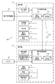
- FIG. 3 is a functional block diagram of the air conditioner 100.
- the outdoor control circuit 17 includes a storage unit 17a and an outdoor control unit 17b.
- the storage unit 17a in addition to a predetermined program and detection values of each sensor, data input from the centralized management device 16 and the like are stored.
- the outdoor control unit 17b controls the compressor motor 1a, the four-way valve 5, the outdoor expansion valve 4, the outdoor fan motor 3a, and the like based on the data stored in the storage unit 17a.
- the indoor control circuit 18 includes a storage unit 18a and an indoor control unit 18b.
- the indoor control unit 18b predeterminedly controls the indoor expansion valve 12, the indoor fan motor 11a, the wind direction plate motor 19, and the like based on the data stored in the storage unit 18a.
- the outdoor control circuit 17 and the indoor control circuit 18 are collectively referred to as “control unit 20”.
- the wind direction plate motor 19 shown in FIG. 3 is a motor that adjusts the wind direction of the air blown into the room by adjusting the angle of the wind direction plate (not shown) of the indoor unit U1.
- a filter (not shown) for collecting dust and dirt is often provided on the air suction side of the indoor heat exchanger 10. However, fine dust and dirt may pass through the filter and adhere to the indoor heat exchanger 10. Therefore, it is desirable to clean the indoor heat exchanger 10 on a regular basis. Therefore, in the first embodiment, after the indoor heat exchanger 10 is frozen (frosted), the indoor heat exchanger 10 is washed by melting the ice and frost of the indoor heat exchanger 10. Such a series of processes is referred to as "cleaning process" of the indoor heat exchanger 10.
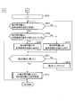
- FIG. 4 is a flowchart of processing executed by the control unit of the air conditioner (see FIGS. 1 and 3 as appropriate). Note that FIG. 4 shows a process related to the cleaning process, and omits other processes (normal air conditioning operation, etc.).
- step S101 the control unit 20 determines whether or not all the indoor units U1, U2, U3, and U4 are stopped. When all the indoor units U1, U2, U3, and U4 are stopped (S101: Yes), the process of the control unit 20 proceeds to step S102. On the other hand, in step S101, when there is at least one indoor unit that is performing air conditioning operation (that is, it is not stopped) (S101: No), the process of the control unit 20 returns to "START" (RETURN).
- the operating point of the pressure in the compressor 1 is significantly different between the cleaning process of freezing the indoor heat exchanger 10 and the normal air conditioning operation. Therefore, when all the indoor units U1, U2, U3, and U4 are stopped, the control unit 20 performs a predetermined determination process (next step S102) regarding the cleaning process.
- step S102 the control unit 20 determines whether or not the integrated value of the air-conditioning operation time of the representative indoor unit (predetermined indoor unit) has reached the predetermined value.
- the representative indoor unit may be appropriately changed by operating the centralized management device 16.
- the integrated value of the air conditioning operation time of the representative indoor unit U1 is, for example, the time during which normal air conditioning operation such as cooling operation or heating operation is performed with reference to the end of the previous cleaning process. Is the sum of the values (the sum of the values).
- step S102 when the integrated value of the air-conditioning operation time of the representative indoor unit U1 has reached a predetermined value (S102: Yes), the process of the control unit 20 proceeds to step S103.
- the processing of the control unit 20 returns to "START" (RETURN). Then, the control unit 20 repeats the processes of steps S101 and S102 until the condition of step S102 is satisfied.
- the representative indoor unit U1 and the other indoor units U2, U3, and U4 are not cleaned.
- control unit 20 is the other indoor unit U2 until the predetermined indoor unit U1 included in the plurality of indoor units U1, U2, U3, U4 starts processing such as freezing of the indoor heat exchanger 10.
- the above-mentioned processing (freezing) is not started.
- the driving frequency of the compressor 1 can be reduced, and the power consumption of the air conditioner 100 can be significantly reduced, as compared with the case where the cleaning process is individually performed for each indoor unit.
- do not start the processing such as freezing of the indoor heat exchanger 10 in the other indoor units U2, U3, U4 means that after the previous cleaning treatment in the other indoor units U2, U3, U4 is performed. This means that the control unit 20 has not yet started the current cleaning process on the other indoor units U2, U3, and U4.
- step S103 the control unit 20 executes the cleaning process not only with the representative indoor unit U1 but also with the other indoor units U2, U3, and U4. That is, the control unit 20 causes the representative indoor unit U1 and the other indoor units U2, U3, and U4 to overlap at least a part of the time zone for performing the cleaning process.
- the timing at which the control unit 20 starts the cleaning process in the indoor units U1, U2, U3, and U4 may be substantially the same.
- the timing at which the control unit 20 ends the cleaning process in the indoor units U1, U2, U3, and U4 may be substantially the same.
- step S103 the process of the control unit 20 returns to "START" (RETURN).
- FIG. 5 is a flowchart of a cleaning process in an air conditioner. That is, FIG. 5 specifically shows the cleaning treatment performed in each of the indoor units U1, U2, U3, and U4 with respect to step S103 of FIG.
- the control unit 20 freezes the indoor heat exchanger 10.
- the control unit 20 causes the indoor heat exchanger 10 to function as an evaporator and frosts the indoor heat exchanger 10.
- the control unit 20 defrosts the indoor heat exchanger 10.
- the control unit 20 causes the indoor heat exchanger 10 to function as a condenser to melt the frost in the indoor heat exchanger 10.
- the dust and dirt of the indoor heat exchanger 10 are washed away by the water accompanying the thawing of the frost.
- step S103c the control unit 20 dries the indoor heat exchanger 10.
- the control unit 20 prohibits the air conditioning operation for a predetermined period from the time of thawing, and dries the indoor heat exchanger 10 by natural convection of air.
- the control unit 20 ends a series of processes related to the cleaning process (END).
- FIG. 6 is a time chart of the cleaning process in the air conditioner (see FIGS. 1 and 3 as appropriate).
- each indoor expansion valve 12 of the indoor units U1, U2, U3, and U4 is described as an “indoor expansion valve”
- each indoor fan 11 is described as an “indoor fan”.
- the air conditioner 100 is stopped at time t0, and the valve body (not shown) of the four-way valve 5 is in the position of the heating cycle.
- the control unit 20 drives the indoor fans 11 of the indoor units U1, U2, U3, and U4 at a predetermined rotation speed Nfi1 at times t1 to t3.
- the control unit 20 drives the outdoor fan 3 at a predetermined rotation speed Nfo1 from the time t2.
- the control unit 20 keeps the outdoor expansion valve 4 in the closed state while driving the outdoor fan 3, and drives the compressor 1 at a relatively low rotation speed Nc2.
- the differential pressure between the high pressure side and the low pressure side of the four-way valve 4 is appropriately adjusted.
- the control unit 20 After performing such a process, the control unit 20 performs a process of freezing the indoor heat exchangers 10 of the indoor units U1, U2, U3, and U4 at times t4 to t5 (S103a in FIG. 5). That is, the control unit 20 switches the four-way valve 5 from the heating cycle to the cooling cycle at time t4. Further, at times t4 to t5, the control unit 20 keeps the outdoor expansion valve 4 open (fully open in the example of FIG. 6), while the indoor expansion valve 12 is narrowed down to a predetermined opening Ei1 and the compressor 1 is set to a predetermined position. It is driven at a rotation speed Nc1.
- the control unit 20 narrows the indoor expansion valves 12 of the indoor units U1, U2, U3, and U4 to a predetermined opening degree Ei1, so that each indoor heat exchanger 10 functions as an evaporator.
- the low-temperature low-pressure refrigerant flows through the indoor heat exchanger 10, and the indoor heat exchanger 10 freezes.
- the control unit 20 keeps the state where the detected value of the indoor heat exchanger temperature sensor 14 (see FIG. 3) is below the freezing point for a predetermined time.
- the control unit 20 drives the outdoor fan 3 at a predetermined rotation speed Nfo1 while stopping each indoor fan 11.
- Nfo1 a predetermined rotation speed
- the control unit 20 may drive the indoor fan 11 at a low speed.
- the control unit 20 After freezing each indoor heat exchanger 10, the control unit 20 drives the compressor 1 at a relatively low rotation speed Nc2 in preparation for thawing of the indoor heat exchanger 10 at times t5 to t6. As a result, the differential pressure between the high pressure side and the low pressure side of the four-way valve 5 is appropriately adjusted. By the way, when the differential pressure on the high pressure side and the low pressure side of the four-way valve 5 is relatively large, as shown in FIG. 6, the control unit 20 decelerates the compressor 1 as a preparation for thawing, but the differential pressure described above. If is too small, the control unit 20 accelerates the compressor 1. Further, the control unit 20 maintains the opening degree of the indoor expansion valve 12 at a predetermined opening degree Ei1 at the time of freezing.
- the control unit 20 switches the four-way valve 5 from the cooling cycle to the heating cycle.
- the four-way valve 5 can be switched while continuing to drive the compressor 1.
- the control unit 20 may temporarily stop the compressor 1, switch the four-way valve 5 from the cooling cycle to the heating cycle, and then thaw the indoor heat exchanger 10. ..
- each indoor heat exchanger 10 time t6 to t7, the control unit 20 narrows the outdoor expansion valve 4 to a predetermined opening Eo1 while opening each indoor expansion valve 12 (in the example of FIG. 6). Fully open).
- the indoor heat exchanger 10 functions as a condenser, and the high-temperature refrigerant flows through the heat transfer tube (not shown) of the indoor heat exchanger 10.
- control unit 20 drives the outdoor fan 3 at a predetermined rotation speed Nfo2 while thawing each indoor heat exchanger 10 (time t6 to t7), while maintaining each indoor fan 11 in a stopped state.
- Nfo2 a predetermined rotation speed
- the control unit 20 may drive the indoor fan 11 at a low speed.
- the control unit 20 dries the indoor heat exchanger 10 for a predetermined time from time t7 (S103c in FIG. 5).
- the control unit 20 stops each device including each indoor fan 11.
- the control unit 20 may prohibit the air conditioning operation based on the operation of the remote controller 15 for a predetermined time from the end of thawing of the indoor heat exchanger 10 (time t7). This prevents cold air from flowing from the indoor units U1, U2, U3, and U4 into the air conditioning chamber, and allows the indoor heat exchanger 10 to be dried by natural convection.
- the control unit 20 uses the other indoor units U1, U2, U3, and U4 until the predetermined indoor unit U1 starts the process of freezing the indoor heat exchanger 10.
- the indoor units U2, U3, and U4 do not start freezing the indoor heat exchanger 10.
- the driving frequency of the compressor 1 can be reduced, and the power consumption of the air conditioner 100 can be significantly reduced, as compared with the case where the cleaning process is individually performed for each indoor unit.
- the indoor heat exchangers 10 are frozen at once, so that the common area of the piping through which the gas refrigerant flows is cooled by the freezing. Can be reduced. Therefore, the power consumption per unit capacity of the indoor units U1, U2, U3, and U4 can be reduced. As described above, according to the first embodiment, it is possible to provide the air conditioner 100 that saves energy in cleaning the plurality of indoor heat exchangers 10.
- the time (total value) required for the cleaning process can be shortened during the predetermined period as compared with the case where the cleaning process is individually performed for each indoor unit.
- the indoor unit can perform air conditioning operation based on the operation of the remote controller 15.
- Second Embodiment For the representative indoor unit U1 and other indoor units U2, U3, and U4, whether or not the cleaning treatment setting is valid, and whether or not the conditions such as the cleaning treatment time zone are satisfied.
- Others configuration of the air conditioner 100, etc .: see FIGS. 1 to 3 are the same as those in the first embodiment. Therefore, a part different from the first embodiment will be described, and a description of the overlapping part will be omitted.
- step S203 is a predetermined value in step S202 (S202: Yes).
- step S202 when the integrated value of the air-conditioning operation time of the representative indoor unit U1 has not reached the predetermined value in step S202 (S202: No), the processing of the control unit 20 returns to "START"("RETURN" in FIG. 7B). ..
- step S203 the control unit 20 determines whether or not the cleaning process setting of the representative indoor unit U1 is valid.
- the cleaning process setting can be enabled / disabled by, for example, the operation of the centralized management device 16 (see FIG. 3) by the administrator (user).
- step S203 when the setting of the cleaning process of the representative indoor unit U1 is enabled (S203: Yes), the process of the control unit 20 proceeds to step S204.
- step S203: No when the setting of the cleaning process of the representative indoor unit U1 is invalid (S203: No), the process of the control unit 20 returns to "START" ("RETURN" in FIG. 7B).
- step S204 the control unit 20 determines whether or not the representative indoor unit U1 satisfies the conditions such as the time zone of the cleaning process.
- the time zone in which the cleaning process is performed the day of the week, the date, and the like can be set by the operation of the centralized management device 16 (see FIG. 3) by the administrator (user).
- step S204 if the representative indoor unit U1 satisfies the conditions such as the cleaning processing time zone (S204: Yes), the processing of the control unit 20 proceeds to step S205.
- the cleaning process is set to be performed during the time zone from 18:00 to 23:00 on Sunday, when the current time is 19:00 on Sunday, the conditions such as the cleaning process time zone are satisfied. Yes (S204: Yes).
- the process of the control unit 20 returns to "START" ("RETURN" in FIG. 7B).
- step S205 the control unit 20 determines the execution of the cleaning process.
- the cleaning treatment is actually performed (S213 in FIG. 7B) after the treatments in steps S206 to S212 in FIG. 7B have been performed on the remaining indoor units U2, U3, and U4.
- This value n is a value used when any one of the indoor units U2, U3, and U4 is designated as the indoor unit Un, and is appropriately incremented (S212).
- the setting of the cleaning process of the other indoor unit Un is enabled (S207: Yes)
- the process of the control unit 20 proceeds to step S208.
- step S208 the control unit 20 determines whether or not the other indoor unit Un satisfies the conditions such as the time zone of the cleaning process.
- step S208 when the other indoor unit Un satisfies the conditions such as the time zone of the cleaning process (S208: Yes), the process of the control unit 20 proceeds to step S209.
- step S209 the control unit 20 includes another indoor unit Un (for example, indoor unit U2) as the target of the cleaning process.
- step S210 the control unit 20 excludes the other indoor unit Un from the cleaning process. For example, when the cleaning process setting of the indoor unit U4 is invalid (S207: No), the control unit 20 excludes the indoor unit U4 from the cleaning process.
- the control unit 20 is the indoor unit in which the setting of the cleaning process (processing such as freezing of the indoor heat exchanger 10) is invalid, or the cleaning process. Exclude indoor units that do not meet at least one of the day, date, and time of day from the cleaning process. Then, after performing the process of step S209 or S210, the process of the control unit 20 proceeds to step S211.
- step S211 the control unit 20 determines whether or not the value n has reached the value N.
- the value N is the total number of indoor units U1, U2, U3, and U4 (4 in the second embodiment), and is stored in advance in the control unit 20. If the value n has not reached the value N in step S211 (S211: No), the process of the control unit 20 proceeds to step S212.
- step S212 the control unit 20 increments the value n. Then, after incrementing the value n, the process of the control unit 20 returns to step S207. In this way, the control unit 20 sequentially determines whether or not the indoor units U2, U3, and U4 can be cleaned.
- step S211 the control unit 20 performs cleaning processing on other indoor units (for example, indoor units U2 and U3) together with the representative indoor unit U1. That is, the control unit 20 executes the cleaning process so that the time zone of the cleaning process of the representative indoor unit U1 and the time zone of the cleaning process of the other indoor units U2 and U3 overlap at least partially.
- the control unit 20 prevents the cleaning process from being performed this time.
- FIG. 8 is a time chart of the cleaning process in the air conditioner. Note that FIG. 8 shows the indoor units U1, U2, and U3 that are included in the cleaning treatment and the indoor units U4 that are excluded from the cleaning treatment separately. , It is different from FIG. 6 of the first embodiment, but is the same as that of FIG. 6 in other points. In the following, the indoor unit U4 that has been excluded from the cleaning treatment will be mainly described, and the description of the other units will be omitted.
- the control unit 20 performs the following processing during the process of freezing the indoor heat exchangers 10 of the indoor units U1, U2, and U3 (time t4 to t5). That is, the control unit 20 causes the indoor heat exchanger 10 of the indoor units U1, U2, U3, which is the target of processing (freezing), to function as an evaporator among the plurality of indoor units U1, U2, U3, U4. , The indoor expansion valve 12 of the indoor unit U4, which is not subject to processing (freezing), is closed. This makes it possible to prevent the low-temperature refrigerant from flowing into the indoor unit U4.
- the control unit 20 exchanges indoor heat of the indoor units U1, U2, U3 which are the targets of the treatment (freezing) among the plurality of indoor units U1, U2, U3, U4.
- the vessel 10 functions as a condenser
- the indoor expansion valve 12 of the indoor unit U4 which is not subject to processing (freezing)
- the frost in each of the indoor heat exchangers 10 of the indoor units U1, U2, and U3 is melted, and the indoor heat exchanger 10 is washed away.
- opening the indoor expansion valve 12 of the indoor unit U4, which is not subject to the cleaning treatment it is possible to prevent the refrigerant from accumulating in the indoor heat exchanger 10 of the indoor unit U4.
- the air conditioner 100 according to the present invention has been described above in each embodiment, the present invention is not limited to these descriptions, and various modifications can be made.
- the process of freezing the indoor heat exchanger 10 has been described, but the present invention is not limited to this. That is, instead of freezing the indoor heat exchanger 10, dew condensation may occur on the indoor heat exchanger 10.
- the control unit 20 determines that the temperature of the indoor heat exchanger 10 is equal to or lower than the dew point of the outside air and is higher than the predetermined freezing temperature.
- the opening degree of 12 and the like are adjusted, and the state is continued for a predetermined time.
- the above-mentioned “freezing temperature” is a temperature at which the moisture contained in the air begins to freeze in the indoor heat exchanger 10 when the temperature of the indoor heat exchanger 10 is gradually lowered.
- the control content is the same as in the case of “freezing” except that the opening degree of the indoor expansion valve 12 is larger in “condensation” than in the case of “freezing” the indoor heat exchanger 10. The same can be said for the second embodiment.
- the control unit 20 has described the process of causing the indoor heat exchanger 10 to function as a condenser and thawing the indoor heat exchanger 10, but the present invention is not limited to this. ..
- the control unit 20 may set the opening degree of the indoor expansion valve 12 to be larger than that at the time of freezing (for example, fully open). As a result, the high-temperature refrigerant flows from the outdoor heat exchanger 2 through the indoor expansion valve 12 into the indoor heat exchanger 10, and the indoor heat exchanger 10 is thawed.
- the cleaning process is executed.
- the starting point for accumulating the air conditioning operation time may be the end of freezing of the indoor unit U1 or the like. That is, when the integrated value of the air-conditioning operation time from the previous end of the process of freezing the indoor heat exchanger 10 of the representative indoor unit U1 reaches a predetermined value, the control unit 20, together with the representative indoor unit U1, other The indoor units U2, U3, and U4 of the above may also execute the above-mentioned processing (freezing).
- the control unit 20 may appropriately drive the indoor fan 11 even when the air conditioning operation such as the cooling operation or the heating operation is not performed. Therefore, the air-conditioning operation time and the driving time of the indoor fan 11 may be different.
- the other indoor units U2, U3, U4 can be operated by operating the remote controller 15. It is preferable that the control unit 20 does not accept this start command when there is a start command for the process (freezing of the indoor heat exchanger 10). As a result, it is possible to prevent the cleaning process from being performed unnecessarily frequently by the operation of each remote controller 15 by a user other than the administrator. Therefore, the power consumption of the air conditioner 100 can be reduced.
- the number of representative indoor units U1 is one has been described, but the number of representative indoor units (predetermined indoor units) may be two or more. Then, for two or more representative indoor units, the sum of the integrated values of the air-conditioning operation times from the previous end of the process of freezing the indoor heat exchanger 10 (or the sum of the sum is the representative indoor unit). When the value) reaches a predetermined value, the control unit 20 executes a process of freezing the indoor heat exchanger 10 not only with two or more representative indoor units but also with other indoor units. It may be. Similarly, for two or more representative indoor units, the sum of the integrated values of the drive times of the indoor fans 11 from the previous end of the process of freezing the indoor heat exchanger 10 (or the sum).
- the control unit 20 freezes the indoor heat exchanger 10 in other indoor units as well as in two or more representative indoor units. May be executed. As a result, the control unit 20 can execute the cleaning process based on the average air-conditioning operation time of two or more representative indoor units. All of the indoor units U1 to U4 may be set as representative indoor units. Even in this case, the control unit 20 can execute the cleaning process at an appropriate frequency based on the above-mentioned air conditioning operation time and the driving time of the indoor fan 11.
- the representative indoor unit U1 may be set based on the identification information of the remote controller 15. That is, the plurality of indoor units U1, U2, U3, and U4 are connected to the representative remote controller 15 (predetermined remote controller) via the wiring m4 (see FIG. 2) to the representative indoor unit U1 (predetermined indoor unit). The machine) and other indoor units U2, U3, U4 connected to the other remote controller 15 via another wiring m4 (see FIG. 2) are included. In such a configuration, it is preferable that the representative remote controller 15 is preset or can be changed based on the operation of the centralized management device 16. As a result, the administrator can appropriately set the representative indoor unit U1 based on the identification information of each remote controller 15.
- a plurality of indoor units may be connected to the representative remote controller 15. Then, the plurality of indoor units are connected to two or more indoor units connected to the representative remote controller 15 (predetermined remote controller) via the wiring m4 and to another remote controller via another wiring m4. Includes other indoor units and.
- the representative indoor unit predetermined indoor unit is a predetermined one indoor unit included in two or more indoor units connected to the representative remote controller 15 via the wiring m4. Is preferable. As a result, the administrator can set a specific indoor unit as a representative even if a plurality of indoor units are connected to one remote controller 15.
- the control unit 20 sends a command. It is preferable to stop the processing (freezing) in the representative indoor unit U1 and the other indoor units U2, U3, and U4, and execute the air conditioning operation in the representative indoor unit U1. As a result, the user's intention to perform air conditioning operation with the representative indoor unit U1 can be appropriately reflected.
- the control unit 20 it is preferable to stop the processing (freezing) of the representative indoor unit U1 (predetermined indoor unit) and the other indoor units U2, U3, and U4, and execute the air conditioning operation with at least one other indoor unit. .. Thereby, for example, the user's intention to perform the air-conditioning operation with the other indoor unit U2 can be appropriately reflected.
- the present invention is not limited to this.
- one or both of thawing and drying of the indoor heat exchanger 10 may be omitted as appropriate. This is because the natural convection of air in the indoor unit promotes thawing or drying of the indoor heat exchanger 10.
- the types of indoor units U1 to U4 are not particularly limited. For example, any one of a plurality of types such as a four-way cassette type, a ceiling-embedded type, a floor-standing type, and a wall-mounted type may be used, or a plurality of types of indoor units may be mixed.
- the configuration in which the outdoor unit Uo (see FIG. 1) includes the outdoor expansion valve 4 and the four-way valve 5 has been described, but the present invention is not limited to this.
- the outdoor expansion valve 4 and the four-way valve 5 may be omitted.
- the configuration in which four indoor units U1, U2, U3, U4 (see FIG. 1) are provided has been described, but the number of indoor units connected in parallel in one system is two or three. It may be a stand, or it may be 5 or more.
- each embodiment the configuration in which the air conditioner 100 (see FIG. 1) includes one outdoor unit Uo has been described, but a configuration in which a plurality of outdoor units are connected in parallel in one system may be used. .. Further, each embodiment can be applied to various types of air conditioners such as a multi air conditioner for buildings (VRF: Variable Refrigerant Flow) and a packaged air conditioner (PAC: Packaged Air Conditioner).
- VRF Variable Refrigerant Flow
- PAC Packaged Air Conditioner
- each embodiment is described in detail in order to explain the present invention in an easy-to-understand manner, and is not necessarily limited to the one including all the configurations described. Further, it is possible to add / delete / replace other configurations with respect to a part of the configurations of each embodiment.
- the above-mentioned mechanism and configuration show what is considered necessary for explanation, and do not necessarily show all the mechanisms and configurations in the product.
- Control unit 100 Air conditioner J1, J2, J3, J4 , J5, J6, J7, J8, J9, J10, J11, J12, J13, J14 piping m4 Wiring Q Refrigerant circuit Uo Outdoor unit U1 Indoor unit (predetermined indoor unit) U2, U3, U4 indoor unit (other indoor unit)
Landscapes
- Engineering & Computer Science (AREA)
- Chemical & Material Sciences (AREA)
- Combustion & Propulsion (AREA)
- Mechanical Engineering (AREA)
- General Engineering & Computer Science (AREA)
- Human Computer Interaction (AREA)
- Physics & Mathematics (AREA)
- Fuzzy Systems (AREA)
- Mathematical Physics (AREA)
- Signal Processing (AREA)
- Air Conditioning Control Device (AREA)
- Air Filters, Heat-Exchange Apparatuses, And Housings Of Air-Conditioning Units (AREA)
Abstract
Description
<空気調和機の構成>
図1は、第1実施形態に係る空気調和機100の冷媒回路Qを含む構成図である。
なお、図1では、冷房サイクル(冷房運転時の冷凍サイクル)における冷媒の流れを実線矢印で示す一方、暖房サイクル(暖房運転時の冷凍サイクル)における冷媒の流れを破線矢印で示している。また、図1では、室外熱交換器2や4つの室内熱交換器10の付近での空気の流れを白抜き矢印で示している。
圧縮機1は、低温低圧のガス冷媒を圧縮し、高温高圧のガス冷媒として吐出する機器であり、駆動源である圧縮機モータ1a(図3参照)を備えている。このような圧縮機1として、例えば、スクロール式圧縮機やロータリ式圧縮機が用いられる。
室外膨張弁4は、室外熱交換器2に流れる冷媒の流量を調整したり、室外熱交換器2を蒸発器として機能させる際に冷媒を減圧したりする電子膨張弁であり、液側の配管J1に設けられている。
アキュムレータ6は、四方弁5を介して流れ込む冷媒を気液分離する殻状部材である。アキュムレータ6によって気液分離された後、ガス状の冷媒が、圧縮機1の吸入側に導かれるようになっている。
なお、図1では図示していないが、圧縮機1の吐出圧力・吐出温度・吸入圧力・吸入温度のうち一つ又は複数を検出するための各センサが適宜に設けられていてもよい。
室内熱交換器10は、その伝熱管(図示せず)を通流する冷媒と、室内ファン11から送り込まれる室内空気(空調室の空気)と、の間で熱交換が行われる熱交換器である。室内熱交換器10の一端h1はガス側の配管J3に接続され、他端h2は液側の配管J2に接続されている。
室内膨張弁12は、室内熱交換器10に流れる冷媒の流量を調整したり、室内熱交換器10を蒸発器として機能させる際に冷媒を減圧したりする電子膨張弁であり、液側の配管J2に設けられている。
室内熱交換器温度センサ14は、室内熱交換器10の温度を検出するセンサである。図1の例では、配管J2において室内熱交換器10の他端h2付近に室内熱交換器温度センサ14が設置されている。
なお、室内熱交換器温度センサ14の位置は、図1の例に限定されない。例えば、配管J3において室内熱交換器10の一端h1付近に室内熱交換器温度センサ14が設置されていてもよい。また、室内熱交換器10に直接的に室内熱交換器温度センサ14が設置されていてもよい。
液側接続部K1,K2,K3は、冷房サイクル中には冷媒を分流させ、また、暖房サイクル中に冷媒を合流させるものである。例えば、冷房サイクル中には、配管J1を通流する冷媒が、液側接続部K1,K2,K3を順次に介して、4つの室内熱交換器10に所定に分配されるようになっている。
図2に示すように、空気調和機100は、前記した構成の他に、リモコン15と、集中管理機器16と、を備えている。また、室外機Uoは室外制御回路17を備える一方、室内機U1,U2,U3,U4は、それぞれ、室内制御回路18を備えている。
例えば、室内機U1に接続されているリモコン15は、ユーザの操作によって、室内機U1に所定の制御指令を与える機能を有している。前記した制御指令として、空気調和機100の運転/停止や、運転モードの切替えや設定温度・風量・風向の変更の他、後記する洗浄処理の開始が挙げられる。なお、他の室内機U2,U3,U4についても同様である。
なお、図3では、4台の室内機U1,U2,U3,U4のうち1台の室内機U1を図示し、残り3台の室内機U2,U3,U4の図示を省略している。
図3に示すように、室外制御回路17は、記憶部17aと、室外制御部17bと、を備えている。記憶部17aには、所定のプログラムや各センサの検出値の他、集中管理機器16から入力されたデータ等が格納される。室外制御部17bは、記憶部17aに格納されているデータに基づいて、圧縮機モータ1a、四方弁5、室外膨張弁4、室外ファンモータ3a等を制御する。
記憶部18aには、所定のプログラムや各センサの検出値の他、リモコン15を介して入力されたデータ等が格納される。室内制御部18bは、記憶部18aに格納されているデータに基づいて、室内膨張弁12や室内ファンモータ11aの他、風向板用モータ19等を所定に制御する。以下では、室外制御回路17及び室内制御回路18を総称して、「制御部20」という。
なお、図3に示す風向板用モータ19は、室内機U1の風向板(図示せず)の角度を調整することで、室内に吹き出される空気の風向きを調整するモータである。
室内熱交換器10の空気吸込側には、塵や埃を捕集するためのフィルタ(図示せず)が設けられていることが多い。しかしながら、細かい塵や埃がフィルタを通り抜けて、室内熱交換器10に付着する可能性がある。したがって、室内熱交換器10を定期的に洗浄することが望ましい。そこで、第1実施形態では、室内熱交換器10を凍結(着霜)させた後、室内熱交換器10の氷や霜を溶かすことで、室内熱交換器10を洗浄するようにしている。このような一連の処理を、室内熱交換器10の「洗浄処理」という。
なお、図4では、洗浄処理に関する処理を示し、他の処理(通常の空調運転等)については省略している。
ステップS101において制御部20は、全ての室内機U1,U2,U3,U4が停止中であるか否かを判定する。全ての室内機U1,U2,U3,U4が停止中である場合(S101:Yes)、制御部20の処理はステップS102に進む。一方、ステップS101において、空調運転を行っている(つまり、停止中ではない)室内機が少なくとも一台存在する場合(S101:No)、制御部20の処理は「START」に戻る(RETURN)。
例えば、制御部20が、室内機U1,U2,U3,U4で洗浄処理を開始するタイミングを略一致させてもよい。また、例えば、制御部20が、室内機U1,U2,U3,U4で洗浄処理を終了するタイミングを略一致させてもよい。また、室内機U1,U2,U3,U4の機種や室内熱交換器10の容量に違いがある場合、室内熱交換器10の凍結時間の長さが異なるものが混在していてもよい。ステップS103の処理を行った後、制御部20の処理は「START」に戻る(RETURN)。
すなわち、図5は、図4のステップS103に関して、それぞれの室内機U1,U2,U3,U4で行われる洗浄処理を具体的に示したものである。
図5のステップS103aにおいて制御部20は、室内熱交換器10を凍結させる。詳細については後記するが、制御部20は、室内熱交換器10を蒸発器として機能させ、室内熱交換器10を着霜させる。
次に、ステップS103bにおいて制御部20は、室内熱交換器10を解凍する。例えば、制御部20は、室内熱交換器10を凝縮器として機能させ、室内熱交換器10の霜を溶かす。これによって、霜の解凍に伴う水で、室内熱交換器10の塵や埃が洗い流される。
以下では、一例として、全ての室内機U1,U2,U3,U4で洗浄処理が行われる場合について説明する。なお、図6では、室内機U1,U2,U3,U4のそれぞれの室内膨張弁12を「室内膨張弁」と記載し、また、それぞれの室内ファン11を「室内ファン」と記載している。
第1実施形態によれば、制御部20は、複数台の室内機U1,U2,U3,U4のうち所定の室内機U1が、室内熱交換器10を凍結させる処理を開始するまで、他の室内機U2,U3,U4では、室内熱交換器10の凍結を開始しない。これによって、室内機ごとに個別に洗浄処理が行われる場合に比べて、圧縮機1の駆動頻度を低減し、ひいては、空気調和機100の消費電力量を大幅に削減できる。
第2実施形態は、代表の室内機U1や他の室内機U2,U3,U4について、洗浄処理の設定が有効であるか否かの他、洗浄処理の時間帯等の条件が満たされているか否かを制御部20が判定する点が、第1実施形態とは異なっている。なお、その他(空気調和機100の構成等:図1~図3参照)については、第1実施形態と同様である。したがって、第1実施形態とは異なる部分について説明し、重複する部分については説明を省略する。
なお、図7AのステップS201,S202の処理は、この順で、図4のステップS101,S102の処理と同様であるから、説明を省略する。
ステップS202において代表の室内機U1の空調運転時間の積算値が所定値に達している場合(S202:Yes)、制御部20の処理はステップS203に進む。一方、ステップS202において代表の室内機U1の空調運転時間の積算値が所定値に達していない場合(S202:No)、制御部20の処理は「START」に戻る(図7Bの「RETURN」)。
ステップS207において制御部20は、他の室内機Unの洗浄処理の設定が有効になっているか否かを判定する。例えば、n=2の場合には、ステップS207において制御部20は、室内機U2の洗浄処理の設定が有効になっているか否かを判定する。他の室内機Unの洗浄処理の設定が有効になっている場合(S207:Yes)、制御部20の処理はステップS208に進む。
ステップS209において制御部20は、他の室内機Un(例えば、室内機U2)を洗浄処理の対象に含める。
ステップS210において制御部20は、他の室内機Unを洗浄処理の対象から外す。例えば、室内機U4の洗浄処理の設定が無効になっている場合(S207:No)、制御部20は、この室内機U4を洗浄処理の対象から外す。
ステップS211において値nが値Nに達していない場合(S211:No)、制御部20の処理はステップS212に進む。
ステップS212において制御部20は、値nをインクリメントする。そして、値nをインクリメントした後、制御部20の処理はステップS207に戻る。このように制御部20は、室内機U2,U3,U4について、洗浄処理の可否を順次に判定する。
ステップS213において制御部20は、代表の室内機U1とともに、他の室内機(例えば、室内機U2,U3)でも洗浄処理を行う。つまり、制御部20は、代表の室内機U1の洗浄処理の時間帯と、他の室内機U2,U3の洗浄処理の時間帯と、が少なくとも部分的に重なるように、洗浄処理を実行する。一方、洗浄処理の対象から外された室内機(例えば、室内機U4)については、制御部20は、今回の洗浄処理を行わないようにする。
なお、図8は、洗浄処理の対象に含まれる室内機U1,U2,U3の各機器と、洗浄処理の対象から外された室内機U4の各機器と、を分けて記載している点が、第1実施形態の図6とは異なるが、それ以外の点については図6と同様である。以下では主に、洗浄処理の対象から外された室内機U4について説明し、それ以外については説明を省略する。
第2実施形態によれば、代表の室内機U1や他の室内機U2,U3,U4のそれぞれについて、洗浄処理の設定が有効になっているか否かの他、洗浄処理の時間帯等の条件が満たされているか否かが判定される。これによって、洗浄処理に関するユーザの設定の自由度を高めることができる。
以上、本発明に係る空気調和機100について各実施形態で説明したが、本発明はこれらの記載に限定されるものではなく、種々の変更を行うことができる。
例えば、第1実施形態では、室内熱交換器10を凍結させる処理について説明したが、これに限らない。すなわち、室内熱交換器10の凍結に代えて、室内熱交換器10を結露させてもよい。このように室内熱交換器10を結露させる場合、制御部20は、室内熱交換器10の温度が、外気の露点以下であり、かつ、所定の凍結温度よりも高くなるように、室内膨張弁12の開度等を調整し、その状態を所定時間継続させる。前記した「凍結温度」とは、室内熱交換器10の温度を徐々に低下させたとき、空気に含まれる水分が室内熱交換器10で凍結し始める温度である。
なお、室内熱交換器10を「凍結」させる場合よりも、「結露」の方が室内膨張弁12の開度が大きい点以外は、「凍結」の場合の制御内容と同様である。また、第2実施形態についても同様のことがいえる。
同様に、2台以上である代表の室内機について、室内熱交換器10を凍結させる処理の前回終了時からの室内ファン11の駆動時間の積算値の和をとった値(若しくは、当該和を代表の室内機の台数で平均した値)が所定値に達した場合、制御部20が、2台以上である代表の室内機とともに、他の室内機でも、室内熱交換器10を凍結させる処理を実行するようにしてもよい。これによって、制御部20は、2台以上である代表の室内機の平均的な空調運転時間等に基づき、洗浄処理を実行できる。
なお、室内機U1~U4の全てが代表の室内機として設定されるようにしてもよい。この場合でも、前記した空調運転時間や室内ファン11の駆動時間に基づいて、制御部20が、洗浄処理を適切な頻度で実行できる。
また、室内機U1~U4の種類は、特に限定されるものではない。例えば、4方向カセット型、天井埋込型、床置型、壁掛型等の複数種類うち、いずれか1種類が用いられてもよいし、また、複数種類の室内機が混在していてもよい。
また、各実施形態では、4台の室内機U1,U2,U3,U4(図1参照)が設けられる構成について説明したが、1系統において並列接続される室内機の台数は、2台や3台であってもよいし、また、5台以上であってもよい。
また、各実施形態は、ビル用マルチエアコン(VRF:Variable Refrigerant Flow)やパッケージエアコン(PAC:Packaged Air Conditioner)といった様々な種類の空気調和機に適用可能である。
また、前記した機構や構成は説明上必要と考えられるものを示しており、製品上必ずしも全ての機構や構成を示しているとは限らない。
2 室外熱交換器
3 室外ファン
4 室外膨張弁
5 四方弁
10 室内熱交換器
11 室内ファン
12 室内膨張弁
15 リモコン
16 集中管理機器
20 制御部
100 空気調和機
J1,J2,J3,J4,J5,J6,J7,J8,J9,J10,J11,J12,J13,J14 配管
m4 配線
Q 冷媒回路
Uo 室外機
U1 室内機(所定の室内機)
U2,U3,U4 室内機(他の室内機)
Claims (10)
- 圧縮機及び室外熱交換器を有する室外機と、室内膨張弁及び室内熱交換器を有する複数台の室内機と、が配管を介して接続されてなる冷媒回路を備えるとともに、
少なくとも前記圧縮機及び複数の前記室内膨張弁を制御する制御部を備え、
前記制御部は、複数台の前記室内機に含まれる所定の室内機が、前記室内熱交換器を凍結又は結露させる処理を開始するまで、他の室内機では、前記処理を開始しない空気調和機。 - 前記制御部は、前記所定の室内機における前記処理の前回終了時からの空調運転時間の積算値、又は、前記所定の室内機における前記処理の前回終了時からの室内ファンの駆動時間の積算値が所定値に達した場合、前記所定の室内機とともに、他の室内機でも前記処理を実行すること
を特徴とする請求項1に記載の空気調和機。 - 前記所定の室内機における前記空調運転時間の積算値又は前記室内ファンの駆動時間の積算値が前記所定値に達していない場合において、リモコンの操作で他の室内機への前記処理の開始指令があったとき、前記制御部は、前記開始指令を受け付けないこと
を特徴とする請求項2に記載の空気調和機。 - 前記所定の室内機の台数は2台以上であり、
2台以上である前記所定の室内機について、前記処理の前回終了時からの空調運転時間の積算値の和をとった値、若しくは、当該和を前記所定の室内機の台数で平均した値が所定値に達した場合、
又は、
2台以上である前記所定の室内機について、前記処理の前回終了時からの室内ファンの駆動時間の積算値の和をとった値、若しくは、当該和を前記所定の室内機の台数で平均した値が所定値に達した場合、
前記制御部は、2台以上である前記所定の室内機とともに、他の室内機でも前記処理を実行すること
を特徴とする請求項1に記載の空気調和機。 - 複数台の前記室内機には、配線を介して所定のリモコンに接続されている前記所定の室内機と、別の配線を介して他のリモコンに接続されている他の室内機と、が含まれ、
前記所定のリモコンは、予め設定されている、又は、集中管理機器の操作に基づいて変更可能であること
を特徴とする請求項1に記載の空気調和機。 - 複数台の前記室内機には、配線を介して所定のリモコンに接続されている2台以上の室内機と、別の配線を介して他のリモコンに接続されている他の室内機と、が含まれ、
前記所定の室内機は、前記所定のリモコンに配線を介して接続されている2台以上の前記室内機に含まれる所定の1台の室内機であること
を特徴とする請求項1に記載の空気調和機。 - 前記制御部は、他の室内機のうち、前記処理の設定が無効になっている室内機、又は、前記処理を行う曜日、日付、及び時間帯のうち少なくとも一つの条件が満たされていない室内機を前記処理の対象から外すこと
を特徴とする請求項1に記載の空気調和機。 - 前記制御部は、
前記処理中、複数台の前記室内機のうち、前記処理の対象である前記室内機の前記室内熱交換器を蒸発器として機能させる一方、前記処理の対象外である前記室内機の前記室内膨張弁を閉じ、
前記処理後、複数台の前記室内機のうち、前記処理の対象である前記室内機の前記室内熱交換器を凝縮器として機能させる一方、前記処理の対象外である前記室内機の前記室内膨張弁を開くこと
を特徴とする請求項7に記載の空気調和機。 - 前記制御部は、前記処理中、リモコン又は集中管理機器の操作で前記所定の室内機への空調運転の指令があった場合、前記所定の室内機及び前記他の室内機での前記処理を中止し、前記所定の室内機で空調運転を実行すること
を特徴とする請求項2に記載の空気調和機。 - 前記制御部は、前記処理中、リモコン又は集中管理機器の操作で前記他の室内機のうち少なくとも一台に空調運転の指令があった場合、前記所定の室内機及び前記他の室内機での前記処理を中止し、少なくとも一台の前記他の室内機で空調運転を実行すること
を特徴とする請求項2に記載の空気調和機。
Priority Applications (6)
| Application Number | Priority Date | Filing Date | Title |
|---|---|---|---|
| KR1020217007972A KR102450678B1 (ko) | 2020-03-05 | 2020-03-05 | 공기 조화기 |
| JP2020539876A JP6786019B1 (ja) | 2020-03-05 | 2020-03-05 | 空気調和機 |
| PCT/JP2020/009328 WO2021176637A1 (ja) | 2020-03-05 | 2020-03-05 | 空気調和機 |
| CN202080005591.5A CN113614459A (zh) | 2020-03-05 | 2020-03-05 | 空调机 |
| EP20891468.9A EP4116635B1 (en) | 2020-03-05 | 2020-03-05 | Air conditioner |
| TW109130715A TWI780478B (zh) | 2020-03-05 | 2020-09-08 | 空調機 |
Applications Claiming Priority (1)
| Application Number | Priority Date | Filing Date | Title |
|---|---|---|---|
| PCT/JP2020/009328 WO2021176637A1 (ja) | 2020-03-05 | 2020-03-05 | 空気調和機 |
Publications (1)
| Publication Number | Publication Date |
|---|---|
| WO2021176637A1 true WO2021176637A1 (ja) | 2021-09-10 |
Family
ID=73219989
Family Applications (1)
| Application Number | Title | Priority Date | Filing Date |
|---|---|---|---|
| PCT/JP2020/009328 Ceased WO2021176637A1 (ja) | 2020-03-05 | 2020-03-05 | 空気調和機 |
Country Status (6)
| Country | Link |
|---|---|
| EP (1) | EP4116635B1 (ja) |
| JP (1) | JP6786019B1 (ja) |
| KR (1) | KR102450678B1 (ja) |
| CN (1) | CN113614459A (ja) |
| TW (1) | TWI780478B (ja) |
| WO (1) | WO2021176637A1 (ja) |
Cited By (1)
| Publication number | Priority date | Publication date | Assignee | Title |
|---|---|---|---|---|
| WO2024034328A1 (ja) * | 2022-08-09 | 2024-02-15 | 三菱重工サーマルシステムズ株式会社 | 空調機及び制御方法 |
Families Citing this family (5)
| Publication number | Priority date | Publication date | Assignee | Title |
|---|---|---|---|---|
| JP7477475B2 (ja) * | 2021-03-12 | 2024-05-01 | ダイキン工業株式会社 | 空気調和機 |
| JP7193750B2 (ja) * | 2021-03-12 | 2022-12-21 | ダイキン工業株式会社 | 空気調和機 |
| JP7227509B2 (ja) * | 2021-03-12 | 2023-02-22 | ダイキン工業株式会社 | 空気調和機 |
| CN114216215B (zh) * | 2021-11-19 | 2023-04-25 | 珠海格力电器股份有限公司 | 水系统的防冻控制方法、装置及相关设备 |
| CN114216203B (zh) * | 2021-12-16 | 2022-10-25 | 珠海格力电器股份有限公司 | 一种多联机空调的自清洁控制方法、多联机空调 |
Citations (5)
| Publication number | Priority date | Publication date | Assignee | Title |
|---|---|---|---|---|
| JP2005098659A (ja) * | 2003-09-26 | 2005-04-14 | Mitsubishi Heavy Ind Ltd | 空気調和設備及び空気調和設備の制御方法 |
| JP2012207867A (ja) * | 2011-03-30 | 2012-10-25 | Hitachi Appliances Inc | 空調管理システム |
| JP6296633B1 (ja) | 2017-04-28 | 2018-03-20 | 日立ジョンソンコントロールズ空調株式会社 | 空気調和機 |
| WO2019220488A1 (ja) * | 2018-05-14 | 2019-11-21 | 日立ジョンソンコントロールズ空調株式会社 | 空気調和機 |
| JP2019215149A (ja) * | 2019-03-26 | 2019-12-19 | 日立ジョンソンコントロールズ空調株式会社 | 空気調和機 |
Family Cites Families (12)
| Publication number | Priority date | Publication date | Assignee | Title |
|---|---|---|---|---|
| TWM305885U (en) * | 2006-08-25 | 2007-02-01 | Wen-Yau Lin | Improved cooling control device for spilt type air-conditioner |
| JP2016138666A (ja) * | 2015-01-26 | 2016-08-04 | ジョンソンコントロールズ ヒタチ エア コンディショニング テクノロジー(ホンコン)リミテッド | 空気調和機 |
| TWI592617B (zh) * | 2016-12-08 | 2017-07-21 | Matsushita Electric (Taiwan) Co Ltd | One to many air-conditioned room where each room air-conditioning power consumption meter Calculation method and one to many air conditioning system |
| CN106969469B (zh) * | 2017-04-07 | 2019-11-29 | 广东美的制冷设备有限公司 | 空调器的控制方法、系统及空调器 |
| JP6387197B1 (ja) * | 2017-04-28 | 2018-09-05 | 日立ジョンソンコントロールズ空調株式会社 | 空気調和機 |
| JP6276450B1 (ja) * | 2017-04-28 | 2018-02-07 | 日立ジョンソンコントロールズ空調株式会社 | 空気調和機 |
| JP6517877B2 (ja) * | 2017-05-26 | 2019-05-22 | 日立ジョンソンコントロールズ空調株式会社 | 空気調和機 |
| JP6360593B1 (ja) * | 2017-05-26 | 2018-07-18 | 日立ジョンソンコントロールズ空調株式会社 | 空気調和機 |
| CN107642866B (zh) * | 2017-08-28 | 2020-04-14 | 青岛海尔空调器有限总公司 | 一种空调自清洁的控制方法及装置 |
| CN108361931B (zh) * | 2018-02-26 | 2020-05-01 | 宁波奥克斯电气股份有限公司 | 多联机自清洁方法及多联机空调系统 |
| CN109882992A (zh) * | 2019-03-08 | 2019-06-14 | 广东美的制冷设备有限公司 | 空调器的滤网清洁控制方法、空调器及可读存储介质 |
| CN110230857B (zh) * | 2019-06-10 | 2020-12-29 | 青岛海尔空调器有限总公司 | 一拖多空调器及其自清洁控制方法 |
-
2020
- 2020-03-05 CN CN202080005591.5A patent/CN113614459A/zh active Pending
- 2020-03-05 EP EP20891468.9A patent/EP4116635B1/en active Active
- 2020-03-05 KR KR1020217007972A patent/KR102450678B1/ko active Active
- 2020-03-05 JP JP2020539876A patent/JP6786019B1/ja active Active
- 2020-03-05 WO PCT/JP2020/009328 patent/WO2021176637A1/ja not_active Ceased
- 2020-09-08 TW TW109130715A patent/TWI780478B/zh active
Patent Citations (5)
| Publication number | Priority date | Publication date | Assignee | Title |
|---|---|---|---|---|
| JP2005098659A (ja) * | 2003-09-26 | 2005-04-14 | Mitsubishi Heavy Ind Ltd | 空気調和設備及び空気調和設備の制御方法 |
| JP2012207867A (ja) * | 2011-03-30 | 2012-10-25 | Hitachi Appliances Inc | 空調管理システム |
| JP6296633B1 (ja) | 2017-04-28 | 2018-03-20 | 日立ジョンソンコントロールズ空調株式会社 | 空気調和機 |
| WO2019220488A1 (ja) * | 2018-05-14 | 2019-11-21 | 日立ジョンソンコントロールズ空調株式会社 | 空気調和機 |
| JP2019215149A (ja) * | 2019-03-26 | 2019-12-19 | 日立ジョンソンコントロールズ空調株式会社 | 空気調和機 |
Non-Patent Citations (1)
| Title |
|---|
| See also references of EP4116635A4 |
Cited By (1)
| Publication number | Priority date | Publication date | Assignee | Title |
|---|---|---|---|---|
| WO2024034328A1 (ja) * | 2022-08-09 | 2024-02-15 | 三菱重工サーマルシステムズ株式会社 | 空調機及び制御方法 |
Also Published As
| Publication number | Publication date |
|---|---|
| EP4116635A4 (en) | 2023-12-06 |
| JP6786019B1 (ja) | 2020-11-18 |
| TW202134572A (zh) | 2021-09-16 |
| TWI780478B (zh) | 2022-10-11 |
| JPWO2021176637A1 (ja) | 2021-09-10 |
| EP4116635A1 (en) | 2023-01-11 |
| EP4116635B1 (en) | 2025-09-17 |
| KR102450678B1 (ko) | 2022-10-06 |
| CN113614459A (zh) | 2021-11-05 |
| KR20210113152A (ko) | 2021-09-15 |
Similar Documents
| Publication | Publication Date | Title |
|---|---|---|
| JP6786019B1 (ja) | 空気調和機 | |
| CN103874892B (zh) | 空气调节装置 | |
| CN111033152B (zh) | 制冷机 | |
| KR100640858B1 (ko) | 공기조화기 및 그 제어방법 | |
| EP2188576A1 (en) | Methods and systems for controlling integrated air conditioning systems | |
| KR101045451B1 (ko) | 멀티 공기 조화기 및 그 제어방법 | |
| JPH09119736A (ja) | 多室型冷暖房装置及びその運転方法 | |
| KR101203995B1 (ko) | 공기조화기 및 그 제상운전방법 | |
| JP7105372B2 (ja) | 空気調和機 | |
| JP7198918B2 (ja) | 空気調和機 | |
| CN114909776A (zh) | 空调器和空调器除霜控制方法 | |
| JP7477475B2 (ja) | 空気調和機 | |
| WO2021192074A1 (ja) | 空気調和機 | |
| JPH02223757A (ja) | 空気調和機 | |
| JP3748620B2 (ja) | 空気調和装置 | |
| JP7749147B1 (ja) | 冷凍サイクル装置 | |
| JP4148676B2 (ja) | 冷凍システム | |
| JP2007298218A (ja) | 冷凍装置 | |
| KR20050065694A (ko) | 보조히터가 장착된 공기조화기의 난방사이클 제어방법 | |
| JP2001330347A (ja) | 空気調和機 | |
| CN115540079A (zh) | 一种空调外机及热泵空调、热泵空调控制方法及装置 | |
| CN115574378A (zh) | 空调器及其控制方法 |
Legal Events
| Date | Code | Title | Description |
|---|---|---|---|
| ENP | Entry into the national phase |
Ref document number: 2020539876 Country of ref document: JP Kind code of ref document: A |
|
| ENP | Entry into the national phase |
Ref document number: 20217007972 Country of ref document: KR Kind code of ref document: A |
|
| 121 | Ep: the epo has been informed by wipo that ep was designated in this application |
Ref document number: 20891468 Country of ref document: EP Kind code of ref document: A1 |
|
| NENP | Non-entry into the national phase |
Ref country code: DE |
|
| ENP | Entry into the national phase |
Ref document number: 2020891468 Country of ref document: EP Effective date: 20221005 |
|
| WWG | Wipo information: grant in national office |
Ref document number: 2020891468 Country of ref document: EP |