WO2021177215A1 - 強化繊維複合材料 - Google Patents
強化繊維複合材料 Download PDFInfo
- Publication number
- WO2021177215A1 WO2021177215A1 PCT/JP2021/007642 JP2021007642W WO2021177215A1 WO 2021177215 A1 WO2021177215 A1 WO 2021177215A1 JP 2021007642 W JP2021007642 W JP 2021007642W WO 2021177215 A1 WO2021177215 A1 WO 2021177215A1
- Authority
- WO
- WIPO (PCT)
- Prior art keywords
- reinforcing fiber
- discontinuous reinforcing
- composite material
- discontinuous
- aggregate
- Prior art date
- Legal status (The legal status is an assumption and is not a legal conclusion. Google has not performed a legal analysis and makes no representation as to the accuracy of the status listed.)
- Ceased
Links
Images


Classifications
-
- B—PERFORMING OPERATIONS; TRANSPORTING
- B29—WORKING OF PLASTICS; WORKING OF SUBSTANCES IN A PLASTIC STATE IN GENERAL
- B29B—PREPARATION OR PRETREATMENT OF THE MATERIAL TO BE SHAPED; MAKING GRANULES OR PREFORMS; RECOVERY OF PLASTICS OR OTHER CONSTITUENTS OF WASTE MATERIAL CONTAINING PLASTICS
- B29B15/00—Pretreatment of the material to be shaped, not covered by groups B29B7/00 - B29B13/00
- B29B15/08—Pretreatment of the material to be shaped, not covered by groups B29B7/00 - B29B13/00 of reinforcements or fillers
- B29B15/10—Coating or impregnating independently of the moulding or shaping step
- B29B15/12—Coating or impregnating independently of the moulding or shaping step of reinforcements of indefinite length
- B29B15/122—Coating or impregnating independently of the moulding or shaping step of reinforcements of indefinite length with a matrix in liquid form, e.g. as melt, solution or latex
-
- C—CHEMISTRY; METALLURGY
- C08—ORGANIC MACROMOLECULAR COMPOUNDS; THEIR PREPARATION OR CHEMICAL WORKING-UP; COMPOSITIONS BASED THEREON
- C08J—WORKING-UP; GENERAL PROCESSES OF COMPOUNDING; AFTER-TREATMENT NOT COVERED BY SUBCLASSES C08B, C08C, C08F, C08G or C08H
- C08J5/00—Manufacture of articles or shaped materials containing macromolecular substances
- C08J5/04—Reinforcing macromolecular compounds with loose or coherent fibrous material
- C08J5/0405—Reinforcing macromolecular compounds with loose or coherent fibrous material with inorganic fibres
- C08J5/042—Reinforcing macromolecular compounds with loose or coherent fibrous material with inorganic fibres with carbon fibres
-
- C—CHEMISTRY; METALLURGY
- C08—ORGANIC MACROMOLECULAR COMPOUNDS; THEIR PREPARATION OR CHEMICAL WORKING-UP; COMPOSITIONS BASED THEREON
- C08J—WORKING-UP; GENERAL PROCESSES OF COMPOUNDING; AFTER-TREATMENT NOT COVERED BY SUBCLASSES C08B, C08C, C08F, C08G or C08H
- C08J5/00—Manufacture of articles or shaped materials containing macromolecular substances
- C08J5/24—Impregnating materials with prepolymers which can be polymerised in situ, e.g. manufacture of prepregs
- C08J5/241—Impregnating materials with prepolymers which can be polymerised in situ, e.g. manufacture of prepregs using inorganic fibres
- C08J5/243—Impregnating materials with prepolymers which can be polymerised in situ, e.g. manufacture of prepregs using inorganic fibres using carbon fibres
-
- B—PERFORMING OPERATIONS; TRANSPORTING
- B29—WORKING OF PLASTICS; WORKING OF SUBSTANCES IN A PLASTIC STATE IN GENERAL
- B29B—PREPARATION OR PRETREATMENT OF THE MATERIAL TO BE SHAPED; MAKING GRANULES OR PREFORMS; RECOVERY OF PLASTICS OR OTHER CONSTITUENTS OF WASTE MATERIAL CONTAINING PLASTICS
- B29B11/00—Making preforms
- B29B11/14—Making preforms characterised by structure or composition
- B29B11/16—Making preforms characterised by structure or composition comprising fillers or reinforcement
-
- C—CHEMISTRY; METALLURGY
- C08—ORGANIC MACROMOLECULAR COMPOUNDS; THEIR PREPARATION OR CHEMICAL WORKING-UP; COMPOSITIONS BASED THEREON
- C08J—WORKING-UP; GENERAL PROCESSES OF COMPOUNDING; AFTER-TREATMENT NOT COVERED BY SUBCLASSES C08B, C08C, C08F, C08G or C08H
- C08J2333/00—Characterised by the use of homopolymers or copolymers of compounds having one or more unsaturated aliphatic radicals, each having only one carbon-to-carbon double bond, and only one being terminated by only one carboxyl radical, or of salts, anhydrides, esters, amides, imides, or nitriles thereof; Derivatives of such polymers
- C08J2333/04—Characterised by the use of homopolymers or copolymers of compounds having one or more unsaturated aliphatic radicals, each having only one carbon-to-carbon double bond, and only one being terminated by only one carboxyl radical, or of salts, anhydrides, esters, amides, imides, or nitriles thereof; Derivatives of such polymers esters
-
- C—CHEMISTRY; METALLURGY
- C08—ORGANIC MACROMOLECULAR COMPOUNDS; THEIR PREPARATION OR CHEMICAL WORKING-UP; COMPOSITIONS BASED THEREON
- C08J—WORKING-UP; GENERAL PROCESSES OF COMPOUNDING; AFTER-TREATMENT NOT COVERED BY SUBCLASSES C08B, C08C, C08F, C08G or C08H
- C08J2363/00—Characterised by the use of epoxy resins; Derivatives of epoxy resins
- C08J2363/10—Epoxy resins modified by unsaturated compounds
Definitions
- the present invention relates to a reinforcing fiber composite material composed of a discontinuous reinforcing fiber and a matrix resin.
- Reinforced fiber composite material consisting of reinforcing fiber and matrix resin is used in the manufacture of various molded products because it can obtain high mechanical properties, and the demand for it is increasing year by year in various fields.
- the reinforcing fiber composite material having high functional properties uses carbon fiber as the reinforcing fiber, and as a molding method of the carbon fiber composite material, it is in the middle of a semi-cured state in which continuous carbon fiber called prepreg is impregnated with a matrix resin.
- the most common practice is autoclave molding, in which a continuous fiber-reinforced composite material in which a matrix resin is cured by laminating base materials and heating and pressurizing in a high-temperature and high-pressure kettle is formed.
- RTM resin transfer molding
- the carbon fiber composite material obtained by these molding methods has excellent mechanical properties because it is a continuous fiber. Further, since the continuous fibers have a regular arrangement, it is possible to design the required mechanical characteristics by arranging the base material, and the variation in the mechanical characteristics is small. However, on the other hand, it is difficult to form a complicated shape such as a three-dimensional shape because it is a continuous fiber, and it is mainly limited to a member having a nearly planar shape.
- Molding methods suitable for complex shapes such as three-dimensional shapes include molding using SMC (sheet molding compound) and stampable sheets.
- SMC sheet molding compound
- the SMC molded product is a sheet-like group in which strands of reinforcing fibers are cut in the direction perpendicular to the fibers so that the fiber length is, for example, about 25 mm, and the chopped strands are impregnated with a matrix resin which is a thermosetting resin to be in a semi-cured state. It is obtained by heating and pressurizing the material (SMC) using a heating type press machine.
- stampable sheet molded product for example, a sheet-like base material (stampable sheet) in which a non-woven fabric mat made of chopped strands cut to about 25 mm or discontinuous reinforcing fibers is impregnated with a thermoplastic resin is once heated with an infrared heater or the like. It is obtained by heating above the melting point of the plastic resin and cooling and pressurizing with a mold having a predetermined temperature.
- stampable sheet a sheet-like base material (stampable sheet) in which a non-woven fabric mat made of chopped strands cut to about 25 mm or discontinuous reinforcing fibers is impregnated with a thermoplastic resin is once heated with an infrared heater or the like. It is obtained by heating above the melting point of the plastic resin and cooling and pressurizing with a mold having a predetermined temperature.
- SMC or stampable sheet is cut smaller than the shape of the molded body, placed on the molding die, and stretched (flowed) into the shape of the molded body by pressurization to perform molding. Therefore, the flow makes it possible to follow a complicated shape such as a three-dimensional shape.
- uneven distribution and uneven orientation of chopped strands and non-woven fabric mats inevitably occur, so that the mechanical properties deteriorate or the values vary widely. ..
- due to the uneven distribution and uneven orientation, warpage, sink marks, etc. are likely to occur especially in thin members.
- Patent Document 1 describes the chopped fiber bundle in the direction of the reinforcing fibers, starting from both ends in the fiber orientation direction in the bundle and toward the center of the chopped fiber bundle. Chopped fiber bundles and molding materials having sections where the number of reinforcing fibers increases have been proposed.
- the discontinuous fiber bundle lengths are different from each other, and the longer the discontinuous fiber bundle length is, the smaller the tip angle forming the acute angle of the end portion of the discontinuous reinforcing fiber bundle when projected on a two-dimensional plane.
- a discontinuous fiber reinforced composite material characterized by the above has been proposed.
- discontinuous reinforcing fibers when discontinuous reinforcing fibers are contained in the matrix resin, the fluidity of the composite material decreases during molding, but the decrease in fluidity is caused by the discontinuous reinforcing fibers. It can be suppressed by increasing the blending amount of the discontinuous reinforcing fiber which is an aggregate form.
- the discontinuous reinforcing fiber bundle has a strip shape when projected onto a two-dimensional plane, the starting point of fracture is around the portion where the fiber bundles overlap and the fiber bundle end portion when the reinforcing fiber composite material is used. Structural defects are likely to occur, and the mechanical properties tend to be inferior.
- the longer the fiber length of the discontinuous reinforcing fiber the better the mechanical properties when it is used as a reinforcing fiber composite material, but the entanglement between the fibers increases and the fluidity is inferior.
- the shorter the fiber length of the discontinuous reinforcing fiber the better the fluidity when the reinforcing fiber composite material is made, but the mechanical property tends to be inferior. That is, the optimum form of the reinforcing fiber composite material that emphasizes good fluidity and the optimum form of the reinforcing fiber composite material that emphasizes mechanical properties are not necessarily the same form.
- the shorter the fiber length of the discontinuous reinforcing fiber the better the fluidity when made into the reinforcing fiber composite material, but the sheet-like base material such as SMC or the stampable sheet which is the precursor of the discontinuous reinforcing fiber composite material.
- the binding force between the discontinuous reinforcing fibers is weak, and the discontinuous reinforcing fibers unintentionally flow as the resin flows, resulting in discontinuity. It causes anisotropy and variation in mechanical properties when it becomes a reinforced fiber composite material.
- the object of the present invention can achieve both high fluidity during molding and high mechanical properties at a high level, which could not be achieved by the conventional reinforcing fiber composite material composed of discontinuous reinforcing fibers and matrix resin.
- the conventional reinforcing fiber composite material composed of discontinuous reinforcing fibers and matrix resin.
- sheet-shaped molding materials such as SMC and stampable sheets, which are precursors of discontinuous reinforcing fiber composite materials
- the matrix resin is pressure-impregnated into the sheet-shaped base material, it is not due to the flow of the resin. It is an object of the present invention to provide an excellent reinforcing fiber composite material which can suppress the flow of continuous reinforcing fibers and has a well-balanced mechanical property.
- the reinforcing fiber composite material of the present invention has the following features.
- the discontinuous reinforcing fiber is contained in an amount of 20 wt% or more and less than 70 wt% and a matrix resin, at least a part of the discontinuous reinforcing fiber forms a fiber aggregate, and at least one bundle of the fiber aggregate is a surface.
- A an arch-shaped discontinuous reinforcing fiber aggregate
- discontinuous reinforcing fiber aggregates when the long side length of the minimum circumscribing rectangle is 30 mm or more as the discontinuous reinforcing fiber aggregate (1), 2 wt% or more in the entire discontinuous reinforcing fibers.
- the discontinuous reinforcing fiber composite material according to [2], wherein at least one bundle of the discontinuous reinforcing fiber aggregate (1) is a bow-shaped discontinuous reinforcing fiber aggregate (A).
- the discontinuous reinforcing fiber aggregate (2) is The ratio of "long side length of number average minimum circumscribing rectangle: number average fiber length" is "1.5: 1.0" to "2.0: 1.0", [1] to [3].
- the number average angle of the acute angle of the tip portion on the longitudinal direction with respect to the longitudinal direction of the projected surface when a certain surface is projected on a two-dimensional plane is 5 ° or more and 30.
- the discontinuous reinforcing fiber is contained in the reinforcing fiber composite material in an amount of 20 wt% or more and less than 70 wt%. It is more preferably 30 wt% or more and 65 wt% or less, and further preferably 40 wt% or more and 60 wt% or less.
- the discontinuous reinforcing fiber is contained in the composite material in an amount of 20 wt% or more, and in order to exhibit high fluidity and moldability, it is contained in an amount of less than 70 wt%.
- the discontinuous reinforcing fiber is contained in an amount of 70 wt% or more, the fluidity and moldability are deteriorated, and at the same time, defects such as voids are likely to be contained in the reinforcing fiber composite material.
- discontinuous reinforcing fibers constitute a fiber aggregate.
- At least one bundle of such fiber aggregates has a projected surface when a certain surface is projected on a two-dimensional plane at both ends in the longitudinal direction of the minimum circumscribing rectangle and at positions other than both ends.
- There is one or more regions in which the number of single yarns constituting the above is reduced hereinafter, may be referred to as a region in which the number of single yarns is reduced).
- the number of fibers decreases toward the ends, and there is one or more regions other than both ends where the number of fibers decreases from the ends toward the center.
- discontinuous reinforcing fiber aggregate A
- the thickness of the fiber bundle in the region where the single yarn is reduced becomes thin, and the fiber bundle can be broken around the end of the discontinuous reinforcing fiber bundle and at the overlapping portion of the discontinuous reinforcing fiber bundles. This is preferable because structural defects that serve as the starting point of the above are less likely to occur.
- the shape of the projected surface obtained by projecting a certain surface onto a two-dimensional plane is a shape as shown in FIG. 2 and a shape in which these are combined. Since the bow-shaped discontinuous reinforcing fiber aggregate (A) has these shapes, structural defects formed around the discontinuous reinforcing fiber bundle end portion and the overlapping portion of the discontinuous reinforcing fiber bundles are less likely to occur. Therefore, it is preferable.
- discontinuous reinforcing fibers do not have to form the bow-shaped discontinuous reinforcing fiber aggregate (A), and other than that, the single yarn level produced when the discontinuous reinforcing fiber sheet is produced.
- Discontinuous reinforcing fibers that have been opened up to, chopped strands that are cut from the strands as they are, split fiber chopped strands in which the chopped strands are divided in the width direction, chopped strands that do not satisfy the bow-shaped discontinuous reinforcing fiber aggregate (A) shape, It may include a widened chopped strand in which the entire chopped strand is widened, a widened split strand in which the entire chopped strand is widened and divided, and the like.
- a discontinuous reinforcing fiber aggregate (1) having a long side length of a minimum circumscribing rectangle of 30 mm or more is 2 wt% of the total discontinuous reinforcing fibers. As mentioned above, it is preferable that it is contained in an amount of 15 wt% or less.
- the matrix resin is used as a sheet-like base in the manufacturing process of a sheet-shaped molding material such as SMC or a stampable sheet which is a precursor of the reinforcing fiber composite material.
- the binding force between the discontinuous reinforcing fibers can be strengthened. Therefore, the unintended flow of the discontinuous reinforcing fiber due to the flow of the resin can be suppressed, and the anisotropy and variation of the mechanical properties when the discontinuous reinforcing fiber composite material is obtained can be reduced.
- the discontinuous reinforcing fiber aggregate (1) is 15 wt% or less, it is possible to suppress a decrease in the fluidity of the discontinuous reinforcing fiber composite material, which is preferable.
- the discontinuous reinforcing fiber aggregate (1) preferably contains at least one bundle of bow-shaped discontinuous reinforcing fiber aggregates (A). Since the long side length of the minimum circumscribing rectangle is relatively long when the discontinuous reinforcing fiber aggregate (1) is projected on a two-dimensional plane, the circumference of the discontinuous reinforcing fiber bundle end and the discontinuous reinforcing fiber bundle Structural defects that are the starting point of fracture may occur in the overlapping parts, but rather, the discontinuous reinforcing fiber aggregate (1) contains at least one bundle of bow-shaped ones, which causes fracture. Structural defects that serve as the starting point are less likely to occur.
- the bow-shaped discontinuous reinforcing fiber aggregate (A) is contained in an amount of 1 wt% or more and 15 wt% or less of the total discontinuous reinforcing fibers so that structural defects that are the starting points of fracture are less likely to occur.
- the discontinuous reinforcing fiber aggregate contained in the discontinuous reinforcing fiber includes the discontinuous reinforcing fiber aggregate (2) in which the long side length of the minimum circumscribing rectangle when projected onto a two-dimensional plane is less than 30 mm.
- the ratio of "long side length of number average minimum circumscribing rectangle: number average fiber length" is preferably "1.5: 1.0" to "2.0: 1.0". Since the long side length of the number average minimum circumscribing rectangle is 1.5 times or more the number average fiber length, structural defects that are the starting points of fracture are unlikely to occur around the discontinuous reinforcing fiber bundle end. Therefore, it is preferable. It is preferable that the long side length of the number average minimum circumscribing rectangle is 2.0 times or less the number average fiber length because the decrease in fluidity of the discontinuous reinforcing fiber composite material can be suppressed.
- the number average angle of the acute angle ⁇ at the tip with respect to the longitudinal direction when projected onto a two-dimensional plane is 5 ° or more and 30 ° or less.
- the number average angle of the acute angle ⁇ at the tip is 5 ° or more, it is possible to suppress a decrease in the fluidity of the discontinuous reinforcing fiber composite material.
- the number average angle of the acute angle ⁇ at the tip portion is 30 ° or less, structural defects that are the starting points of fracture are less likely to occur around the discontinuous reinforcing fiber bundle end portion, which is preferable.
- the bow-shaped discontinuous reinforcing fiber aggregate (A) has a gradient of a region where single threads existing at positions other than both ends decrease with respect to the longitudinal direction of the minimum circumscribing rectangle on the projection plane when projected onto a two-dimensional plane. It is preferable that the number average angle of the obtuse angle ⁇ formed by the object is 135 ° or more and 175 ° or less. When the number average angle of the obtuse angle ⁇ is within the range of 135 ° or more and 175 ° or less, the thickness of the fiber bundles tends to be thin when the discontinuous reinforcing fiber bundles overlap each other, and there are structural defects that are the starting points of fracture. It is preferable because it is less likely to occur.
- the discontinuous reinforcing fiber preferably has a number average fiber length of 3 mm or more and less than 100 mm. It is preferable that the length of the number average fiber length is within the range of 3 mm or more and less than 100 mm because good fluidity and mechanical properties can be compatible with each other in a well-balanced manner.
- the reinforcing fibers used in the present invention include organic fibers such as aramid fibers, polyethylene fibers and polyparaphenylene benzoxador (PBO) fibers, glass fibers, carbon fibers, silicon carbide fibers, alumina fibers, tyranno fibers, genbuiwa fibers and ceramics. Reinforcing fiber bundles using inorganic fibers such as fibers, metal fibers such as stainless steel fibers and steel fibers, boron fibers, natural fibers, and modified natural fibers are preferable.
- organic fibers such as aramid fibers, polyethylene fibers and polyparaphenylene benzoxador (PBO) fibers, glass fibers, carbon fibers, silicon carbide fibers, alumina fibers, tyranno fibers, genbuiwa fibers and ceramics.
- Reinforcing fiber bundles using inorganic fibers such as fibers, metal fibers such as stainless steel fibers and steel fibers, boron fibers, natural fibers,
- carbon fibers are the lightest of these reinforcing fibers, and have particularly excellent properties in terms of specific strength and specific elastic modulus, and further have heat resistance and chemical resistance. It is preferable because it has excellent properties.
- PAN polyacrylonitrile
- the carbon fiber is not particularly limited, but high-strength, high elastic modulus carbon fiber can be used, and these may be used alone or in combination of two or more. Among them, PAN-based, pitch-based, rayon-based and other carbon fibers can be mentioned. From the viewpoint of the balance between the strength and elastic modulus of the obtained molded product, PAN-based carbon fibers are preferable.
- the density of the carbon fiber is preferably one having 1.65 ⁇ 1.95g / cm 3, further more preferably from 1.70 ⁇ 1.85g / cm 3. If the density is too high, the lightweight performance of the obtained carbon fiber composite material may be inferior, and if the density is too low, the mechanical properties of the obtained carbon fiber composite material may be low.
- the carbon fibers used in the present invention are preferably carbon fiber strands in which single yarns are converged from the viewpoint of productivity, and those having a large number of single yarns in the carbon fiber strands are preferable.
- the number of single yarns in the case of carbon fiber strands is preferably in the range of 1,000 to 100,000, and particularly preferably in the range of 10,000 to 70,000.
- a split carbon fiber strand obtained by dividing the carbon fiber strand into a desired number of strands using a strand fiber slitter or the like, or a partially split carbon fiber strand partially fiber-treated is specified as needed. It may be cut to the length of. By splitting the strands into a desired number of strands, the uniformity of the carbon fiber composite material is improved as compared with the untreated strands, and the mechanical properties are excellent, which is preferably exemplified.
- the partial defibration treatment comprises a widening treatment and a partial defibration treatment
- the widening treatment includes, for example, passing a reinforcing fiber strand through a vibrating roll and heating, rubbing, and rocking by each opening bar.
- Examples thereof include a vibration widening method in which the fiber bundle is widened in the width direction, and an air widening method in which compressed air is blown onto the reinforcing fiber bundle.
- the widening width of the reinforcing fiber strand a preferable example is that the widening ratio is 300 to 1,200%.
- a rotary defibration means for example, defibration
- the processing iron plate is inserted into the widening reinforcing fiber strand to generate a fiber-dividing treatment portion, and an entangled portion in which single yarns are entangled is formed at a contact portion with a protruding portion in at least one fiber-dividing processing portion.
- a method of pulling out the defibrating means from the widening reinforcing fiber strand, passing through the entangled accumulating portion including the entangled portion, and then inserting the defibrating means into the widening reinforcing fiber strand again is preferably exemplified.
- thermoplastic resin As the matrix resin used in the present invention, a thermoplastic resin and / or a thermosetting resin is used.
- the thermoplastic resin is not particularly limited, and can be appropriately selected as long as it does not significantly deteriorate the mechanical properties of the molded product.
- polyolefin resins such as polyethylene resin and polypropylene resin
- polyamide resins such as nylon 6 resin and nylon 6,6 resin
- polyester resins such as polyethylene terephthalate resin and polybutylene terephthalate resin
- polyphenylene sulfide resin polyether ketone resin
- Polyether sulfone resin, aromatic polyamide resin and the like can be used.
- any of polyamide resin, polypropylene resin, and polyphenylene sulfide resin is preferable.
- thermosetting resin is not particularly limited, and can be appropriately selected as long as the mechanical properties of the molded product are not significantly deteriorated.
- epoxy resin, unsaturated polyester resin, vinyl ester resin, phenol resin, epoxy acrylate resin, urethane acrylate resin, phenoshiki resin, alkyd resin, urethane resin, maleimide resin, cyanate resin and the like can be used.
- any one of epoxy resin, unsaturated polyester resin, vinyl ester resin, and phenol resin, or a mixture thereof is preferable.
- the thermosetting resins to be mixed have compatibility with each other or have a high affinity with each other.
- the viscosity of the thermosetting resin used in the present invention is not particularly limited, but the resin viscosity at room temperature (25 ° C.) is preferably 100 to 100,000 mPa ⁇ s.
- thermoplastic resin used in the present invention
- various additives can be added to the thermoplastic resin and / or the thermosetting resin as long as the object of the present invention can be achieved.
- Fillers such as titanium, zinc oxide, antimony oxide, calcium polyphosphate, graphite, barium sulfate, magnesium sulfate, zinc borate, subcalcium borate, aluminum borate whisker, potassium titanate whisker and polymer compounds, Conductivity imparting materials such as metal-based, metal oxide-based, carbon black and graphite powder, Halogen flame retardants such as brominated resin, antimon flame retardants such as antimon trioxide and antimon pentoxide, phosphorus flame retardants such as ammonium polyphosphate, aromatic phosphate and red phosphorus, metal borate salts, metal carboxylates Organic acid metal salt flame retardants such as salts and aromatic sulfonimide metal salts, inorganic flame retardants such as zinc borate, zinc, zinc oxide and zirconium compounds, cyanulic acid, isocyanuric acid, melamine, melamine cyanurate, melamine phosphate and Nitrogen-based flame retardants such as guanidine nitrogenized, fluorine-
- Flame retardants such as cadmium oxide, zinc oxide, cuprous oxide, cupric oxide, ferrous oxide, ferric oxide, cobalt oxide, manganese oxide, molybdenum oxide, tin oxide and titanium oxide, pigments and dyes.
- Lubricants, mold release agents, compatibilizers, dispersants, crystal nucleating agents such as mica, talc and kaolin, plasticizing agents such as phosphate esters, heat stabilizers, antioxidants, color inhibitors, UV absorbers, fluidization Sex modifiers, foaming agents, antibacterial agents, vibration damping agents, deodorants, slidable modifiers, antistatic agents such as polyether ester amide and the like may be added.
- thermosetting resin When a thermosetting resin is used as the matrix resin, additives such as a low shrinkage agent can be added as long as the object of the present invention can be achieved.
- the step of obtaining the molding material which is the precursor of the reinforcing fiber composite material of the present invention is not particularly limited as long as the object of the present invention can be achieved.
- the first carrier sheet is pulled out from the first sheet roll 11 and supplied to the conveyor 12, and the matrix resin paste is spread by the doctor blade by the first resin bath 13 to a predetermined thickness.
- the first resin sheet 14 is traveling at a constant speed by the conveyor 12.
- a continuous reinforcing fiber strand 22 is pulled out from the bobbin 21, continuously cut by a cutting machine 23 so as to have a predetermined length, and then collided with a distributor (distributor) 24 to form a plurality of discontinuous reinforcing fiber aggregates.
- the discontinuous reinforcing fibers containing the fibers are generated and sprayed on the first resin sheet 14.
- an aggregate 31 in which discontinuous reinforcing fibers including the discontinuous reinforcing fiber aggregate are randomly scattered is continuously formed on the traveling first resin sheet 14.
- a long second carrier sheet is pulled out from the second sheet roll 15, and a matrix resin paste is applied onto the surface of the second carrier sheet by the second resin bath 16.
- the second resin sheet 17 is formed by applying the above to a predetermined thickness.
- the second resin sheet 17 is traveling at a constant speed by the conveyor 12, and the second resin sheet 17 is laminated so that the upper surface of the aggregate 31 and the surface coated with the matrix resin paste are in contact with each other.
- the matrix resin applied to the first resin sheet 14 and the second resin sheet 17 is partially inside the aggregate 31 in which the discontinuous reinforcing fibers including the discontinuous reinforcing fiber aggregate are randomly sprayed.
- the aggregate 32 impregnated with is continuously formed.
- the aggregate 32 is pressed from both sides or one side by the pressurizing mechanism 33 to impregnate the discontinuous reinforcing fibers with the matrix resin (impregnation step), and the discontinuous reinforcement is performed between the first carrier sheet and the second carrier sheet.
- a molding material 34 which is a precursor of the fiber composite material, is formed. An example is a step in which the molding material 34 is wound into a roll together with the first carrier sheet 14 and the second carrier sheet 17.
- the cutting machine 23 is not particularly limited as long as it does not hinder the subject of the present invention, and a guillotine blade type or a disk blade type is exemplified.
- the disk blade type is a cutter roll so that the blade portions 42 of the disk blade are adjacent to or in contact with the cutter roll 41 having a shape protruding at predetermined intervals on the roll surface 40.
- From the traverse guide 51 that guides the reinforcing fiber strand 22 while reciprocating left and right when the nip roll 50 and the reinforcing fiber strand 22 which are installed substantially parallel to the rotation axis direction and have a flat surface shape are put into the cutter roll 41.
- the nip roll 50 acts as a cutting board with respect to the cutter roll 41, it is preferable to use an elastic material such as rubber or urethane as the material of the roll surface.
- the traverse guide 51 that guides the reinforcing fiber strand 22 while reciprocating left and right moves from right to left or vice versa.
- the distance between the blade portions 42 of the disk blades protruding from the peripheral cutter roll surface 40 into which the reinforcing fiber strands 22 are charged is narrower than the width of the reinforcing fiber strands charged into the cutter roll. It can be illustrated.
- the relationship between the distance between the blade portions 42 of the disk blade protruding on the surface of the cutter roll and the width of the reinforcing fiber strands is 0.1: 1.0 to 0.9: 1.0, which can be exemplified as a preferable example. ..
- the acceleration when the traverse guide that guides the reinforcing fiber strands reciprocate to the left and right turns from right to left or vice versa is 1 G (gravitational acceleration) or more.
- the discontinuous reinforcing fibers applied to the cut surface obtained by cutting the sample so as to have a size of 150 mm ⁇ 150 mm are excluded from the measurement target.
- the extracted discontinuous reinforcing fiber aggregate is placed on a flat table and projected onto a two-dimensional plane using a camera or the like, and the minimum circumscribing rectangle is obtained for the obtained shape, and the length of the minimum circumscribing rectangle is obtained. Record the lengths of the side L and the short side W.
- the short side length W of the minimum circumscribing rectangle is less than 0.5 mm.
- Discontinuous reinforcing fiber aggregates having a W of 0.5 mm or more are summarized as discontinuous reinforcing fiber aggregates (1) for discontinuous reinforcing fiber aggregates having a long side length L of 30 mm or more, and have a long side length.
- the discontinuous reinforcing fiber aggregates having an L of less than 30 mm were summarized as the discontinuous reinforcing fiber aggregates (2).
- the same measurement may be performed from the discontinuous reinforcing fiber sheet that is not impregnated with the matrix resin.
- W1 Discontinuous reinforcing fiber aggregate (1) Total weight W2: Discontinuous reinforcing fiber aggregate (2) Total weight W3: Discontinuous reinforcing fiber aggregate (3) Total weight.
- the average value of the two tip angles ( ⁇ 1, ⁇ 2) was taken as the individual tip angle ⁇ i of the discontinuous reinforcing fiber aggregate.
- ⁇ i the average value of the two tip angles
- Number average tip angle ⁇ ⁇ i / n ⁇ i: Individual tip angles of discontinuous reinforcing fiber aggregates (1) and (2) n: Number of fiber aggregates obtained by determining individual tip angles of discontinuous reinforcing fiber aggregates (1) and (2).
- the discontinuous reinforcing fiber aggregate (1) contains at least one bundle and the bow-shaped discontinuous reinforcing fiber aggregate (A) is included (Yes), and if not even one bundle is contained (No). bottom.
- Wy W4 / (W1 + W2 + W3) x 100 (%) W4: The total weight of the bow-shaped discontinuous reinforcing fiber aggregate (A) existing in the discontinuous reinforcing fiber aggregate (1) and the discontinuous reinforcing fiber aggregate (2).
- obtuse angle the same value is used. If there are two obtuse angles, two obtuse angles are used. The average value of the angles was taken as the individual obtuse angle ⁇ i of the bow-shaped discontinuous reinforcing fiber aggregate (A). However, if the obtuse angle apex in the area where the number of single threads starts to decrease is unclear, a tangent line is drawn on each side, the point where the extension lines of the tangent line intersect is the obtuse angle apex, and the angle formed by the extension line of the tangent line is the obtuse angle. Often, if measurement is difficult, such as when the edge shape is clearly distorted, only one side may be used, and if both sides are clearly distorted, it is excluded from the measurement target.
- Number average obtuse angle ⁇ ⁇ i / m ⁇ i: Individual obtuse angle of the bow-shaped discontinuous reinforcing fiber assembly (A) m: Number of fiber aggregates obtained by obtaining the individual obtuse angle of the bow-shaped discontinuous reinforcing fiber assembly (A).
- Number average fiber length l ⁇ li / p li: Individual fiber length of discontinuous reinforcing fiber aggregate (2) p: Number of fiber aggregates obtained by determining individual fiber length of discontinuous reinforcing fiber aggregate (2).
- the bending strength was measured according to JIS-K7171: 2016. Regarding the bending strength, the CV value of the bending strength (coefficient of variation [%]) was also calculated, and a CV value of 10% or less was judged to have a small variation (OK), and a CV value of more than 10% was regarded as a large variation (NG).
- the sample to be subjected to the bending test is measured in the arbitrary direction (0 ° direction) of the two-dimensional plane and in the 90 ° direction with respect to the 0 ° direction, and the average value in the 0 ° direction / the average value in the 90 ° direction. When is in the range of 1.2 to 0.83, it is determined to be isotropic (OK), and otherwise, it is determined to be anisotropic (NG).
- Reinforcing fiber strand (1) A continuous carbon fiber strand having a fiber diameter of 7 ⁇ m, a tensile elastic modulus of 230 GPa, a number of filaments of 12,000, and a strand width of 6 mm was used.
- Reinforcing fiber strand (2) A continuous carbon fiber strand having a fiber diameter of 7.2 ⁇ m, a tensile elastic modulus of 242 GPa, a number of filaments of 50,000, and a strand width of 10 mm was used.
- Matrix resin (1) Vinyl ester resin (VE) resin (manufactured by Dow Chemical Co., Ltd., Deraken 790) 100 parts by mass, tert-butyl peroxybenzoate (manufactured by Nippon Oil & Fats Co., Ltd., perbutyl Z) 1 part by mass, zinc stearate (Sakai Chemical Co., Ltd.) A resin obtained by mixing 2 parts by mass of SZ-2000 manufactured by Kogyo Co., Ltd. and 4 parts by mass of magnesium oxide (MgO # 40 manufactured by Kyowa Chemical Industry Co., Ltd.) was used.
- VE Vinyl ester resin
- SZ-2000 manufactured by Kogyo Co., Ltd.
- MgO # 40 manufactured by Kyowa Chemical Industry Co., Ltd.
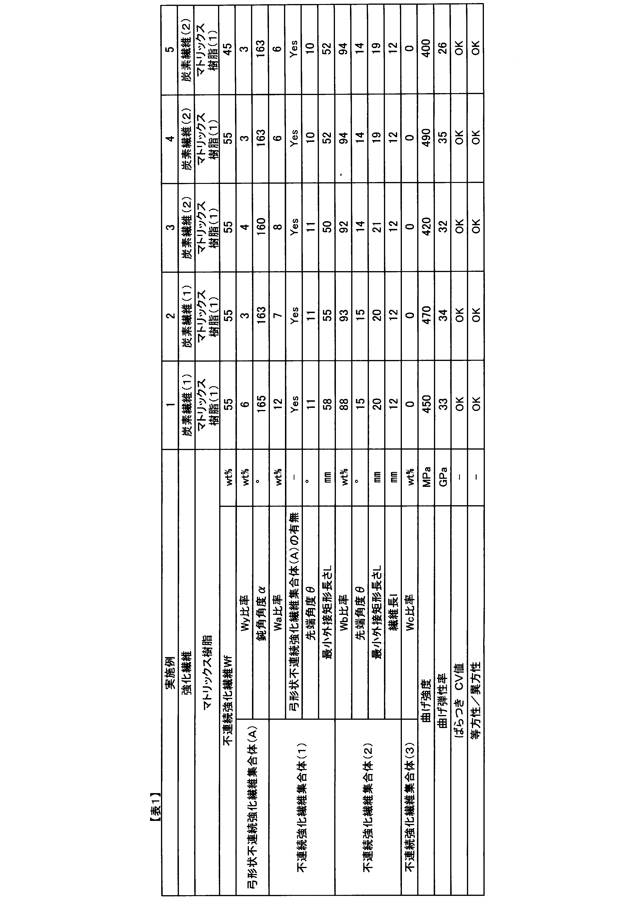
- Example 1 An SMC sheet, which is a precursor of a discontinuous reinforcing fiber composite material, was prepared using an apparatus as shown in FIG. A polypropylene first carrier sheet is pulled out from the first raw fabric roll (first sheet roll) and supplied to the first conveyor, and a matrix resin paste is applied to a predetermined thickness using a doctor blade to apply the first resin. A sheet was formed.
- the reinforcing fiber strand (1) is continuously cut to a predetermined length without slack by a disk blade type cutting machine consisting of a nip roll installed substantially parallel to the rotation axis direction of the cutter roll so as to make contact with each other.
- the discontinuous reinforcing fibers including a plurality of discontinuous reinforcing fiber aggregates continuously generate sheet-shaped discontinuous reinforcing fibers in which the discontinuous reinforcing fibers including a plurality of discontinuous reinforcing fiber aggregates are randomly oriented by colliding with and dispersing the disperser. Dropped on the seat. At this time, the ratio of the pull-out speed and the traverse speed is 3.7: 1.0, the folding distance of the traverse guide is 100 mm, and the ratio of the distance between the blades of the disk blade and the width of the reinforcing fiber strand (1) is 0. 4: 1.0, the rotation speed of the distributor was 400 rpm.
- a polypropylene second carrier sheet is pulled out from the second raw fabric roll (second sheet roll) and supplied to the second conveyor, and the matrix resin paste is applied to a predetermined thickness using a doctor blade. A second resin sheet was formed.
- a second resin sheet is laminated together with a second carrier sheet on a first resin sheet containing a discontinuous reinforcing fiber aggregate, and pressure is applied from both sides to impregnate the sheet composed of the discontinuous reinforcing fiber aggregate with a matrix resin.
- the SMC sheet which is a precursor of the discontinuous reinforcing fiber composite material, was prepared. With respect to the obtained SMC sheet, an SMC sheet having a predetermined width could be obtained without the SMC sheet flowing in the sheet width direction in the direction perpendicular to the transport direction in the impregnation step. Then, the produced SMC sheet was cured at a temperature of 25 ⁇ 5 ° C. for one week after production, and each evaluation was carried out.
- the obtained SMC sheet was cut out to a predetermined size, the upper and lower carrier sheets were peeled off, organic substances such as matrix resin were burned off, and the Wf was measured.
- the bow-shaped discontinuous reinforcing fiber aggregate was contained in the discontinuous reinforcing fiber in an amount of 6 wt%. The evaluation results are shown in Table 1.
- the SMC sheet was cut out to 265 x 265 mm, the transport direction (MD direction) in the SMC sheet manufacturing apparatus was aligned, three sheets were stacked, and placed in the center of a flat plate mold having a cavity of 300 x 300 mm (charge rate). After that, it was cured by a heating type press molding machine under a pressure of 10 MPa under the condition of about 140 ° C. ⁇ 5 minutes to obtain a flat molded product of 300 ⁇ 300 mm ⁇ 3 mm.
- Example 2 A molded product was manufactured and evaluated in the same manner as in Example 1 except that the folding distance of the traverse guide was set to 160 mm and an SMC sheet which was a precursor of the composite material was obtained. The results are shown in Table 1.
- Example 3 Using the reinforcing fiber strand (2), the folding distance of the traverse guide is set to 160 mm, the ratio of the distance between the blades of the disk blade and the width of the reinforcing fiber strand (2) is 0.24: 1.0, and the precursor of the composite material is set.
- a molded product was manufactured and evaluated in the same manner as in Example 1 except that the SMC sheet which was the body was obtained. The results are shown in Table 1.
- Example 4 The reinforcing fiber strand (2) is unwound at a constant speed by a winder, and the unwound reinforcing fiber strand (2) is passed through a vibrating widening roll that vibrates in the axial direction at 10 Hz to widen the reinforcing fiber bundle, and then regulated to a width of 50 mm. A widening reinforcing fiber strand (2) widened to 50 mm was obtained by passing through the width-regulating roll. Next, the iron plates for fiber splitting having a protruding shape having a thickness of 0.3 mm, a width of 3 mm, and a height of 20 mm were arranged at equal intervals of 3 mm with respect to the width direction of the widening reinforcing fiber strand (2). After the processing means was intermittently inserted and removed, a partially fiber-reinforced fiber strand (2) whose width was regulated to 10 mm was prepared by passing it through a width regulating roll regulated to a width of 10 mm.
- the folding distance of the traverse guide was set to 160 mm, and the ratio of the distance between the blades of the disk blade and the width of the partially fiber-reinforced fiber strand (2) was 0.24 :.
- a molded product was produced and evaluated in the same manner as in Example 1 except that the SMC sheet, which was a precursor of the reinforcing fiber composite material, was set to 1.0. The results are shown in Table 1.
- Example 5 When organic substances such as matrix resin were burned off on the SMC sheet and Wf was measured, the speed at which the carrier sheet was pulled out so that it was 45 wt% and the clearance between the doctor blade and the carrier sheet were adjusted to be a precursor of the reinforcing fiber composite material. A molded product was produced and evaluated in the same manner as in Example 4 except that an SMC sheet was obtained. The results are shown in Table 1.
- Comparative Example 1 The first guillotine type cutting machine in which one blade is set diagonally with respect to the strand transport direction and the minimum circumscribing rectangular length is 20 mm so that the minimum circumscribing rectangular length is 60 mm and the tip cutting angle is 15 °.
- a second guillotine cutting machine in which one blade is set diagonally with respect to the strand transport direction so that the tip cutting angle is 15 °, the reinforcing fiber strand (2) is subjected to the first guillotine.
- the speed ratio between the type cutting machine and the second guillotine type cutting machine is 12:88, so that the reinforcing fiber strands (2) have a predetermined length without slack in each guillotine type cutting machine.
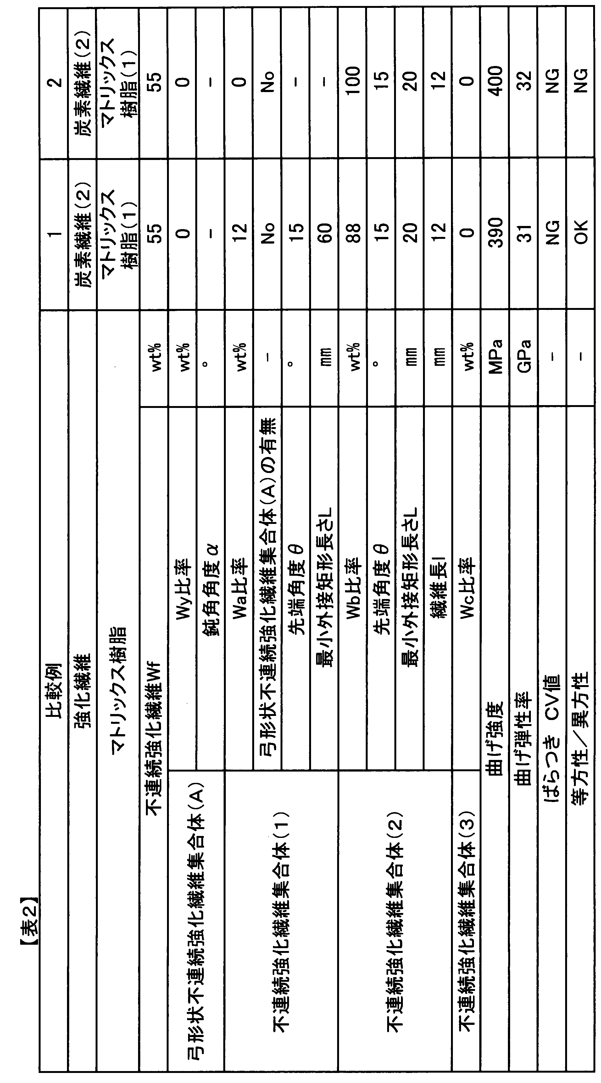
- the obtained molded product is inferior in bending strength and flexural modulus, and in particular, since it does not contain an arch-shaped discontinuous reinforcing fiber aggregate, structural defects formed in the overlapping portion of the discontinuous reinforcing fiber bundles are likely to occur. Probably because of this, the CV value exceeded 10%, and the molded product had a large variation.
- Comparative Example 2 Reinforcing fiber strands using only a second guillotine type cutting machine in which one blade is set diagonally with respect to the strand transport direction so that the minimum circumscribing rectangular length is 20 mm and the tip cutting angle is 15 °. (2) is continuously cut with a guillotine type cutting machine so as to have a predetermined length without sagging, collides with and dispersed in a disperser (distributor), and discontinuously strengthened including a plurality of discontinuous reinforcing fiber aggregates.
- a molded product was produced and evaluated in the same manner as in Example 3 except that sheet-shaped discontinuous reinforcing fibers in which the fibers were randomly oriented were continuously produced to obtain an SMC sheet as a precursor of the composite material. .. The results are shown in Table 2.
- the obtained SMC sheet flowed in the sheet width direction perpendicular to the transport direction in the impregnation step, and became an SMC sheet exceeding a predetermined width.
- the molded product is inferior in bending strength and flexural modulus, and in particular, the SMC sheet flows in the sheet width direction in the impregnation process, and the average value in the 0 ° direction / the average value in the 90 ° direction is in the range of 1.2 to 0.83. It was a molded product having anisotropy exceeding the above.
- the reinforcing fiber composite material of the present invention can achieve both high fluidity during molding and high mechanical properties at a high level, which could not be achieved by the conventional reinforcing fiber composite material composed of discontinuous reinforcing fibers and matrix resin.
- sheet-shaped molding materials such as SMC sheets and stampable sheets, which are precursors of composite materials
- the matrix resin when the matrix resin is pressure-impregnated into the sheet-shaped base material, it is discontinuous due to the flow of the resin. The flow of reinforcing fibers can be suppressed.
- Example of the form of the bow-shaped discontinuous reinforcing fiber assembly (A) 2
- Example of the minimum circumscribing rectangle of the bow-shaped discontinuous reinforcing fiber assembly (A) L Example of the long side length of the minimum circumscribing rectangle W Short of the minimum circumscribing rectangle Example of side length ⁇ 1 , ⁇ 2
- Example of blunt angle of discontinuous reinforcing fiber assembly 11
- Example of first sheet roll 12
- Example of 1st resin bath 14 Example of 1st resin sheet coated with matrix resin paste to a predetermined thickness 15
- Example of 2nd sheet roll 16
- Example of 2nd resin sheet 21 Example of reinforcing fiber strand bobbin 22
- Example of continuous reinforcing fiber strand 23
- Example of cutting machine 24
Landscapes
- Chemical & Material Sciences (AREA)
- Engineering & Computer Science (AREA)
- Materials Engineering (AREA)
- Inorganic Chemistry (AREA)
- Manufacturing & Machinery (AREA)
- Health & Medical Sciences (AREA)
- Chemical Kinetics & Catalysis (AREA)
- Medicinal Chemistry (AREA)
- Polymers & Plastics (AREA)
- Organic Chemistry (AREA)
- Mechanical Engineering (AREA)
- Reinforced Plastic Materials (AREA)
Abstract
Description
[1]不連続強化繊維を20wt%以上70wt%未満と、マトリックス樹脂とを含み、前記不連続強化繊維の少なくとも一部は繊維集合体をなし、前記繊維集合体の少なくとも1束は、ある面を2次元平面上に投影した際に、投影面の最小外接矩形長手方向における両端部と、両端部以外のそれぞれに、前記繊維集合体を構成する単糸本数が減少する領域が1ヵ所以上存在する(以下、弓形状不連続強化繊維集合体(A)という)、不連続強化繊維複合材料。
[2]前記不連続強化繊維集合体のうち、前記最小外接矩形の長辺長さが30mm以上あるものを不連続強化繊維集合体(1)としたとき、不連続強化繊維全体における2wt%以上15wt%以下が不連続強化繊維集合体(1)を形成する、[1]に記載の不連続強化繊維複合材料。
[3]前記不連続強化繊維集合体(1)の少なくとも1束は弓形状不連続強化繊維集合体(A)である、[2]に記載の不連続強化繊維複合材料。
[4]前記繊維集合体のうち、前記最小外接矩形の長辺長さが30mm未満であるものを不連続強化繊維集合体(2)としたとき、不連続強化繊維集合体(2)は、「数平均最小外接矩形の長辺長さ:数平均繊維長」の比が、「1.5:1.0」~「2.0:1.0」である、[1]~[3]に記載の不連続強化繊維複合材料。
[5]前記不連続強化繊維集合体(1)は、ある面を2次元平面上に投影した際の投影面の長手方向に対する前記長手方向上の先端部鋭角の数平均角度が、5°以上30°以下である、[2]~[4]に記載の不連続強化繊維複合材料。
[6]前記不連続強化繊維集合体(2)は、ある面を2次元平面上に投影した際の投影面の長手方向に対する前記長手方向上の先端部鋭角の数平均角度が5°以上30°以下である、[4]~[5]に記載の不連続強化繊維複合材料。
[7]弓形状不連続強化繊維集合体(A)の前記投影面の最小外接矩形長手方向に対し、両端部以外の位置に存在する前記単糸本数が減少する領域の勾配がなす数平均鈍角角度が135°以上175°以下である、[1]~[7]に記載の不連続強化繊維複合材料。
[8]前記不連続強化繊維は、数平均繊維長の長さが3mm以上100mm未満である、[1]~[8]に記載の不連続強化繊維複合材料。
例えば、マイカ、タルク、カオリン、ハイドロタルサイト、セリサイト、ベントナイト、ゾノトライト、セピオライト、スメクタイト、モンモリロナイト、ワラステナイト、シリカ、炭酸カルシウム、ガラスビーズ、ガラスフレーク、ガラスマイクロバルーン、クレー、二硫化モリブデン、酸化チタン、酸化亜鉛、酸化アンチモン、ポリリン酸カルシウム、グラファイト、硫酸バリウム、硫酸マグネシウム、ホウ酸亜鉛、ホウ酸亜カルシウム、ホウ酸アルミニウムウィスカ、チタン酸カリウムウィスカおよび高分子化合物などの充填材、
金属系、金属酸化物系、カーボンブラックおよびグラファイト粉末などの導電性付与材、
臭素化樹脂などのハロゲン系難燃剤、三酸化アンチモンや五酸化アンチモンなどのアンチモン系難燃剤、ポリリン酸アンモニウム、芳香族ホスフェートおよび赤燐などのリン系難燃剤、有ホウ酸金属塩、カルボン酸金属塩および芳香族スルホンイミド金属塩などの有機酸金属塩系難燃剤、硼酸亜鉛、亜鉛、酸化亜鉛およびジルコニウム化合物などの無機系難燃剤、シアヌル酸、イソシアヌル酸、メラミン、メラミンシアヌレート、メラミンホスフェートおよび窒素化グアニジンなどの窒素系難燃剤、PTFEなどのフッ素系難燃剤、ポリオルガノシロキサンなどのシリコーン系難燃剤、水酸化アルミニウムや水酸化マグネシウムなどの金属水酸化物系難燃剤、その他の難燃剤、
酸化カドミウム、酸化亜鉛、酸化第一銅、酸化第二銅、酸化第一鉄、酸化第二鉄、酸化コバルト、酸化マンガン、酸化モリブデン、酸化スズおよび酸化チタンなどの難燃助剤、顔料、染料、滑剤、離型剤、相溶化剤、分散剤、マイカ、タルクおよびカオリンなどの結晶核剤、リン酸エステルなどの可塑剤、熱安定剤、酸化防止剤、着色防止剤、紫外線吸収剤、流動性改質剤、発泡剤、抗菌剤、制振剤、防臭剤、摺動性改質剤、およびポリエーテルエステルアミドなどの帯電防止剤等を添加しても良い。
不連続強化繊維複合材料もしくは前駆体である成形材料から150mm×150mmとなるサンプルを切り出し、その切り出したサンプルを500~600℃に加熱した電気炉の中で1~2時間程度加熱し、マトリックス樹脂等の有機物を焼き飛ばし、そのサンプルから不連続強化繊維シートを取り出した。ピンセット等を用いて、不連続強化繊維シートから不連続強化繊維を集合体単位で全て形が崩れないように慎重に抽出した。この際に、150mm×150mmとなるようにサンプルを切り出した切断面にかかる不連続強化繊維は測定対象から除外する。抽出した不連続強化繊維集合体について、平らな台の上に置き、カメラ等を用いて2次元平面上に投影し、得られた形状に対して、最小外接矩形を求め、最小外接矩形の長辺Lと短辺Wの長さを記録する。
1/10,000gまで測定が可能な天秤を用いて、前記不連続強化繊維集合体(1)、不連続強化繊維集合体(2)、不連続強化繊維集合体(3)の全ての重量を測定し、下記式を用いて、不連続強化繊維全体重量に対する不連続強化繊維集合体(1)の重量比率Wa、不連続強化繊維集合体(2)の重量比率Wb、不連続強化繊維集合体(3)の重量比率Wcを求める。
Wa=W1/(W1+W2+W3)×100(%)
Wb=W2/(W1+W2+W3)×100(%)
Wc=W3/(W1+W2+W3)×100(%)
W1:不連続強化繊維集合体(1)総重量
W2:不連続強化繊維集合体(2)総重量
W3:不連続強化繊維集合体(3)総重量。
デジタルマイクロスコープ(キーエンス社製)を用いて、前記不連続強化繊維集合体(1)、不連続強化繊維集合体(2)に対して、個々に2次元平面上に投影した際に、図5に示すように、不連続強化繊維集合体の長手方向に対する端部鋭角頂点と端部鋭角頂点を中心として、半径2mmの円を描いた際に円と辺が交わる点を直線で結んだ際のなす角の角度を不連続強化繊維集合体の片側先端角度θ1とし、対となる端部に対しても同様の測定を行い、2つの先端角度(θ1、θ2)の平均値を不連続強化繊維集合体の個々の先端角度θiとした。ただし、先端形状が明らかに崩れている等の測定が困難な場合は片側のみを用いてもよく、両側とも測定が困難な場合は、測定対象から除外する。
数平均先端角度θ=Σθi/n
θi:不連続強化繊維集合体(1)、(2)の個々の先端角度
n:不連続強化繊維集合体(1)、(2)の個々の先端角度を求めた繊維集合体本数。
前記不連続強化繊維集合体(1)、不連続強化繊維集合体(2)に対して、目視にて図2に示す弓形状不連続強化繊維集合体(A)に該当する束を全て抽出し、1/10,000gまで測定が可能な天秤を用いて、弓形状不連続強化繊維集合体(A)の全ての重量を測定し、下記式を用いて、弓形状不連続強化繊維集合体(A)の重量比率Wyを求める。
このとき不連続強化繊維集合体(1)に少なくとも1束以上、弓形状不連続強化繊維集合体(A)が含まれていれば(Yes)、1束も含まれていなければ(No)とした。
Wy=W4/(W1+W2+W3)×100(%)
W4:不連続強化繊維集合体(1)、不連続強化繊維集合体(2)中に存在する弓形状不連続強化繊維集合体(A)総重量。
数平均鈍角角度α=Σαi/m
αi:弓形状不連続強化繊維集合体(A)の個々の鈍角角度
m:弓形状不連続強化繊維集合体(A)の個々の鈍角角度を求めた繊維集合体本数。
デジタルマイクロスコープ(キーエンス社製)を用いて、前記不連続強化繊維集合体(2)に対して、個々に2次元平面上に投影した際に、不連続強化繊維集合体中の繊維配向方向に平行な2端辺を0.1mm単位まで測定し、平均値を不連続強化繊維集合体(2)の個々の繊維長liとした。ただし、端辺形状が明らかに崩れている等の測定が困難な場合は片側のみを用いてもよく、両側が明らかに崩れている場合は、測定対象から除外する。
数平均繊維長l=Σli/p
li:不連続強化繊維集合体(2)の個々の繊維長
p:不連続強化繊維集合体(2)の個々の繊維長を求めた繊維集合体本数。
強化繊維複合材料から150mm×150mmとなるサンプルを切り出し、その重量を測定した。その後、サンプルを500~600℃に加熱した電気炉の中で1~2時間程度加熱してマトリックス樹脂等の有機物を焼き飛ばし、室温まで冷却してから、残った不連続強化繊維の重量を測定した。マトリックス樹脂等の有機物を焼き飛ばす前のサンプルの重量に対する不連続強化繊維の重量の比率を測定し、不連続強化繊維の含有率とした。
JIS-K7171:2016に準拠して曲げ強度を測定した。曲げ強度については曲げ強度のCV値(変動係数[%])も算出し、CV値が10%以下をばらつきが小さい(OK)と判定し、10%超をばらつきが大きい(NG)とした。また、曲げ試験を行うサンプルは2次元平面の任意の方向(0°方向)と0°方向に対して90°方向に対して測定を行い、0°方向の平均値/90°方向の平均値が1.2~0.83の範囲に入る場合は等方性(OK)と判定し、それ以外を異方性(NG)と判定した。
本発明の実施例、比較例で用いた強化繊維、マトリックス樹脂について説明する。
繊維径7μm、引張弾性率230GPa、フィラメント数12,000本、ストランド幅6mmの連続した炭素繊維ストランドを用いた。
繊維径7.2μm、引張弾性率242GPa、フィラメント数50,000本、ストランド幅10mmの連続した炭素繊維ストランドを用いた。
ビニルエステル樹脂(VE)樹脂(ダウ・ケミカル(株)製、デラケン790)100質量部、tert-ブチルパーオキシベンゾエート(日本油脂(株)製、パーブチルZ)1質量部、ステアリン酸亜鉛(堺化学工業(株)製、SZ-2000)2質量部、酸化マグネシウム(協和化学工業(株)製、MgO#40)4質量部を混合した樹脂を用いた。
図3に示すような装置を用いて不連続強化繊維複合材料の前駆体であるSMCシートを作成した。第1の原反ロール(第1シートロール)からポリプロピレン製の第1キャリアシートを引き出して第1コンベヤへと供給し、マトリックス樹脂ペーストをドクターブレードを用いて所定の厚みで塗布して第1樹脂シートを形成した。
トラバースガイドの折り返し距離を160mmにし、複合材料の前駆体であるSMCシートを得た以外は実施例1と同様にして成形品を製造し、評価を実施した。結果を表1に示す。
強化繊維ストランド(2)を用い、トラバースガイドの折り返し距離を160mmにし、円盤刃の刃部の間隔と強化繊維ストランド(2)の幅の比率を0.24:1.0とし、複合材料の前駆体であるSMCシートを得た以外は実施例1と同様にして成形品を製造し、評価を実施した。結果を表1に示す。
強化繊維ストランド(2)をワインダーによって一定速度で巻出し、巻き出した強化繊維ストランド(2)を10Hzで軸方向に振動する振動拡幅ロールに通して強化繊維束を拡幅した後に、50mm幅に規制された幅規制ロールを通すことで50mmへ拡幅した拡幅強化繊維ストランド(2)を得た。次に厚み0.3mm、幅3mm、高さ20mmの突出形状を具備する分繊処理用鉄製プレートを、拡幅強化繊維ストランド(2)の幅方向に対して、3mmの等間隔に並べた分繊処理手段を間欠式に抜き挿しした後に、10mm幅に規制された幅規制ロールを通すことで10mmへ幅を規制した部分分繊強化繊維ストランド(2)を作成した。
SMCシートにマトリックス樹脂等の有機物を焼き飛ばし、Wfを測定したところ、45wt%となるようにキャリアシートを引き出す速度、ドクターブレードとキャリアシート間のクリアランスを調整し強化繊維複合材料の前駆体であるSMCシートを得た以外は実施例4と同様にして成形品を製造し、評価を実施した。結果を表1に示す。
最小外接矩形長さが60mm、先端切断角度が15°となるように、ストランド搬送方向に対して1枚の刃が斜めにセットされた第1のギロチン式切断機と最小外接矩形長さが20mm、先端切断角度が15°となるように、ストランド搬送方向に対して1枚の刃が斜めにセットされた第2のギロチン式切断機を用いて、強化繊維ストランド(2)を第1のギロチン式切断機と第2のギロチン式切断機に搬送する速度比が12:88となるように搬送し、強化繊維ストランド(2)がそれぞれのギロチン式切断機でたるみなく所定の長さとなるように連続的に切断し、分散器(ディストリビューター)に衝突、分散させて、複数の不連続強化繊維集合体を含む不連続強化繊維がランダムに配向したシート状不連続強化繊維を連続的に生成し、複合材料の前駆体であるSMCシートを得た以外は実施例3と同様にして成形品を製造し、評価を実施した。結果を表2に示す。
最小外接矩形長さが20mm、先端切断角度が15°となるように、ストランド搬送方向に対して1枚の刃が斜めにセットされた第2のギロチン式切断機のみを用いて、強化繊維ストランド(2)をギロチン式切断機でたるみなく所定の長さとなるように連続的に切断し、分散器(ディストリビューター)に衝突、分散させて、複数の不連続強化繊維集合体を含む不連続強化繊維がランダムに配向したシート状不連続強化繊維を連続的に生成し、複合材料の前駆体であるSMCシートを得た以外は実施例3と同様にして成形品を製造し、評価を実施した。結果を表2に示す。
2 弓形状不連続強化繊維集合体(A)の最小外接矩形の一例
L 最小外接矩形の長辺長さの一例
W 最小外接矩形の短辺長さの一例
θ1、θ2 不連続強化繊維集合体の先端鋭角角の一例
α1、α2 不連続強化繊維集合体の鈍角角の一例
11 第1シートロールの一例
12 コンベヤの一例
13 第1樹脂バスの一例
14 マトリックス樹脂のペーストを所定の厚みで塗布した第1樹脂シートの一例
15 第2シートロールの一例
16 第2樹脂バスの一例
17 マトリックス樹脂のペーストを所定の厚みで塗布した第2樹脂シートの一例
21 強化繊維ストランドボビンの一例
22 連続強化繊維ストランドの一例
23 切断機の一例
24 分散器(ディストリビューター)の一例
31 第1樹脂シート上に、不連続強化繊維がランダムに散布された集合体の一例
32 第1樹脂シート及び第2樹脂シートに塗布されたマトリックス樹脂が部分的に含浸した集合体
33 加圧機構の一例
34 不連続強化繊維複合材料の前駆体である成形材料の一例
40 円盤刃式切断機のカッターロール表面の一例
41 円盤刃式切断機のカッターロールの一例
42 円盤刃の刃部の一例
50 円盤刃式切断機のニップロールの一例
51 円盤刃式切断機のトラバースガイドの一例
60 円盤刃式切断機で得られる不連続強化繊維集合体の一例
70 不連続強化繊維集合体(2)の一例
l1、l2 不連続強化繊維集合体の繊維長の一例
Claims (8)
- 不連続強化繊維を20wt%以上70wt%未満と、マトリックス樹脂とを含み、前記不連続強化繊維の少なくとも一部は繊維集合体をなし、
前記繊維集合体の少なくとも1束は、ある面を2次元平面上に投影した際に、投影面の最小外接矩形長手方向における両端部と、両端部以外のそれぞれに、前記繊維集合体を構成する単糸本数が減少する領域が1ヵ所以上存在する(以下、弓形状不連続強化繊維集合体(A)という)、強化繊維複合材料。 - 前記繊維集合体のうち、前記最小外接矩形の長辺長さが30mm以上あるものを不連続強化繊維集合体(1)としたとき、
不連続強化繊維全体における2wt%以上15wt%以下が不連続強化繊維集合体(1)を形成する、請求項1に記載の強化繊維複合材料。 - 前記不連続強化繊維集合体(1)の少なくとも1束は弓形状不連続強化繊維集合体(A)である、請求項2に記載の強化繊維複合材料。
- 前記繊維集合体のうち、前記最小外接矩形の長辺長さが30mm未満であるものを不連続強化繊維集合体(2)としたとき、
不連続強化繊維集合体(2)は、「数平均最小外接矩形の長辺長さ:数平均繊維長」の比が、「1.5:1.0」~「2.0:1.0」である、請求項1~3のいずれかに記載の強化繊維複合材料。 - 前記不連続強化繊維集合体(1)は、ある面を2次元平面上に投影した際の投影面の長手方向に対する前記長手方向上の先端部鋭角の数平均角度が、5°以上30°以下である、請求項2~4のいずれかに記載の強化繊維複合材料。
- 前記不連続強化繊維集合体(2)は、ある面を2次元平面上に投影した際の投影面の長手方向に対する前記長手方向上の先端部鋭角の数平均角度が5°以上30°以下である、請求項4または5に記載の強化繊維複合材料。
- 弓形状不連続強化繊維集合体(A)の前記投影面の最小外接矩形長手方向に対し、両端部以外の位置に存在する前記単糸本数が減少する領域の勾配がなす数平均鈍角角度が135°以上175°以下である、請求項1~6のいずれかに記載の強化繊維複合材料。
- 前記不連続強化繊維は、数平均繊維長が3mm以上100mm未満である、請求項1~7のいずれかに記載の強化繊維複合材料。
Priority Applications (5)
| Application Number | Priority Date | Filing Date | Title |
|---|---|---|---|
| ES21765040T ES3022265T3 (en) | 2020-03-02 | 2021-03-01 | Reinforcing-fiber composite material |
| JP2021512292A JP7743787B2 (ja) | 2020-03-02 | 2021-03-01 | 強化繊維複合材料 |
| CN202180017769.2A CN115243854B (zh) | 2020-03-02 | 2021-03-01 | 增强纤维复合材料 |
| US17/800,922 US12528924B2 (en) | 2020-03-02 | 2021-03-01 | Reinforcing-fiber composite material |
| EP21765040.7A EP4116054B1 (en) | 2020-03-02 | 2021-03-01 | Reinforcing-fiber composite material |
Applications Claiming Priority (2)
| Application Number | Priority Date | Filing Date | Title |
|---|---|---|---|
| JP2020-034762 | 2020-03-02 | ||
| JP2020034762 | 2020-03-02 |
Publications (1)
| Publication Number | Publication Date |
|---|---|
| WO2021177215A1 true WO2021177215A1 (ja) | 2021-09-10 |
Family
ID=77613334
Family Applications (1)
| Application Number | Title | Priority Date | Filing Date |
|---|---|---|---|
| PCT/JP2021/007642 Ceased WO2021177215A1 (ja) | 2020-03-02 | 2021-03-01 | 強化繊維複合材料 |
Country Status (6)
| Country | Link |
|---|---|
| US (1) | US12528924B2 (ja) |
| EP (1) | EP4116054B1 (ja) |
| JP (1) | JP7743787B2 (ja) |
| CN (1) | CN115243854B (ja) |
| ES (1) | ES3022265T3 (ja) |
| WO (1) | WO2021177215A1 (ja) |
Citations (6)
| Publication number | Priority date | Publication date | Assignee | Title |
|---|---|---|---|---|
| WO2008149615A1 (ja) | 2007-06-04 | 2008-12-11 | Toray Industries, Inc. | チョップド繊維束、成形材料、および、繊維強化プラスチック、ならびに、これらの製造方法 |
| JP2009062474A (ja) * | 2007-09-07 | 2009-03-26 | Toray Ind Inc | 成形材料、繊維強化プラスチックおよびそれらの製造方法 |
| WO2016047412A1 (ja) * | 2014-09-25 | 2016-03-31 | 東レ株式会社 | 強化繊維複合材料 |
| WO2017145884A1 (ja) | 2016-02-25 | 2017-08-31 | 東レ株式会社 | 不連続繊維強化複合材料 |
| WO2018143067A1 (ja) * | 2017-02-02 | 2018-08-09 | 東レ株式会社 | 部分分繊繊維束およびその製造方法、ならびにそれを用いたチョップド繊維束および繊維強化樹脂成形材料 |
| WO2020067058A1 (ja) * | 2018-09-28 | 2020-04-02 | 東レ株式会社 | 繊維強化樹脂成形材料および成形品 |
Family Cites Families (9)
| Publication number | Priority date | Publication date | Assignee | Title |
|---|---|---|---|---|
| GB0222753D0 (en) * | 2002-10-02 | 2002-11-06 | Carbon Fibre Technology Ltd | Method of production of advanced composite materials |
| JP2009062648A (ja) * | 2007-09-07 | 2009-03-26 | Toray Ind Inc | チョップド繊維束、成形材料、および繊維強化プラスチックの製造方法 |
| JP2009114611A (ja) * | 2007-10-16 | 2009-05-28 | Toray Ind Inc | チョップド繊維束および成形材料の製造方法、成形材料、繊維強化プラスチック |
| JP2009274412A (ja) * | 2008-05-19 | 2009-11-26 | Toray Ind Inc | 不連続繊維からなる一方向シート基材の製造方法 |
| KR102339964B1 (ko) * | 2015-07-01 | 2021-12-17 | 도레이 카부시키가이샤 | 촙드 섬유 다발의 제조 장치 및 그 제조 방법 |
| WO2017145883A1 (ja) * | 2016-02-25 | 2017-08-31 | 東レ株式会社 | 不連続繊維強化複合材料 |
| JP6774651B2 (ja) * | 2016-10-05 | 2020-10-28 | 東レ株式会社 | チョップド繊維束の製造装置 |
| US10994510B2 (en) * | 2016-12-22 | 2021-05-04 | Toray Industries, Inc. | Composite structure and method for manufacturing same |
| JP7013873B2 (ja) * | 2016-12-22 | 2022-02-01 | 東レ株式会社 | 加工品の製造方法および加工品 |
-
2021
- 2021-03-01 CN CN202180017769.2A patent/CN115243854B/zh active Active
- 2021-03-01 WO PCT/JP2021/007642 patent/WO2021177215A1/ja not_active Ceased
- 2021-03-01 JP JP2021512292A patent/JP7743787B2/ja active Active
- 2021-03-01 EP EP21765040.7A patent/EP4116054B1/en active Active
- 2021-03-01 US US17/800,922 patent/US12528924B2/en active Active
- 2021-03-01 ES ES21765040T patent/ES3022265T3/es active Active
Patent Citations (6)
| Publication number | Priority date | Publication date | Assignee | Title |
|---|---|---|---|---|
| WO2008149615A1 (ja) | 2007-06-04 | 2008-12-11 | Toray Industries, Inc. | チョップド繊維束、成形材料、および、繊維強化プラスチック、ならびに、これらの製造方法 |
| JP2009062474A (ja) * | 2007-09-07 | 2009-03-26 | Toray Ind Inc | 成形材料、繊維強化プラスチックおよびそれらの製造方法 |
| WO2016047412A1 (ja) * | 2014-09-25 | 2016-03-31 | 東レ株式会社 | 強化繊維複合材料 |
| WO2017145884A1 (ja) | 2016-02-25 | 2017-08-31 | 東レ株式会社 | 不連続繊維強化複合材料 |
| WO2018143067A1 (ja) * | 2017-02-02 | 2018-08-09 | 東レ株式会社 | 部分分繊繊維束およびその製造方法、ならびにそれを用いたチョップド繊維束および繊維強化樹脂成形材料 |
| WO2020067058A1 (ja) * | 2018-09-28 | 2020-04-02 | 東レ株式会社 | 繊維強化樹脂成形材料および成形品 |
Non-Patent Citations (1)
| Title |
|---|
| See also references of EP4116054A4 |
Also Published As
| Publication number | Publication date |
|---|---|
| US20230077555A1 (en) | 2023-03-16 |
| ES3022265T3 (en) | 2025-05-28 |
| CN115243854A (zh) | 2022-10-25 |
| EP4116054B1 (en) | 2025-03-12 |
| JP7743787B2 (ja) | 2025-09-25 |
| EP4116054A4 (en) | 2024-04-03 |
| US12528924B2 (en) | 2026-01-20 |
| CN115243854B (zh) | 2025-03-04 |
| EP4116054A1 (en) | 2023-01-11 |
| JPWO2021177215A1 (ja) | 2021-09-10 |
Similar Documents
| Publication | Publication Date | Title |
|---|---|---|
| JP6874677B2 (ja) | 不連続繊維強化複合材料 | |
| JP6874678B2 (ja) | 不連続繊維強化複合材料 | |
| JP5843048B1 (ja) | スタンパブルシート | |
| JP5920546B1 (ja) | 強化繊維複合材料 | |
| TWI701273B (zh) | 強化纖維複合材料 | |
| WO2021177215A1 (ja) | 強化繊維複合材料 |
Legal Events
| Date | Code | Title | Description |
|---|---|---|---|
| ENP | Entry into the national phase |
Ref document number: 2021512292 Country of ref document: JP Kind code of ref document: A |
|
| 121 | Ep: the epo has been informed by wipo that ep was designated in this application |
Ref document number: 21765040 Country of ref document: EP Kind code of ref document: A1 |
|
| NENP | Non-entry into the national phase |
Ref country code: DE |
|
| ENP | Entry into the national phase |
Ref document number: 2021765040 Country of ref document: EP Effective date: 20221004 |
|
| WWG | Wipo information: grant in national office |
Ref document number: 202180017769.2 Country of ref document: CN |
|
| WWG | Wipo information: grant in national office |
Ref document number: 17800922 Country of ref document: US |