WO2021181602A1 - シール構造及びそれを備えた計量装置 - Google Patents
シール構造及びそれを備えた計量装置 Download PDFInfo
- Publication number
- WO2021181602A1 WO2021181602A1 PCT/JP2020/010785 JP2020010785W WO2021181602A1 WO 2021181602 A1 WO2021181602 A1 WO 2021181602A1 JP 2020010785 W JP2020010785 W JP 2020010785W WO 2021181602 A1 WO2021181602 A1 WO 2021181602A1
- Authority
- WO
- WIPO (PCT)
- Prior art keywords
- top plate
- connecting portion
- feeder
- seal structure
- center substrate
- Prior art date
- Legal status (The legal status is an assumption and is not a legal conclusion. Google has not performed a legal analysis and makes no representation as to the accuracy of the status listed.)
- Ceased
Links
Images

Classifications
-
- B—PERFORMING OPERATIONS; TRANSPORTING
- B65—CONVEYING; PACKING; STORING; HANDLING THIN OR FILAMENTARY MATERIAL
- B65G—TRANSPORT OR STORAGE DEVICES, e.g. CONVEYORS FOR LOADING OR TIPPING, SHOP CONVEYOR SYSTEMS OR PNEUMATIC TUBE CONVEYORS
- B65G27/00—Jigging conveyors
- B65G27/08—Supports or mountings for load-carriers, e.g. framework, bases, spring arrangements
-
- G—PHYSICS
- G01—MEASURING; TESTING
- G01G—WEIGHING
- G01G19/00—Weighing apparatus or methods adapted for special purposes not provided for in the preceding groups
- G01G19/387—Weighing apparatus or methods adapted for special purposes not provided for in the preceding groups for combinatorial weighing, i.e. selecting a combination of articles whose total weight or number is closest to a desired value
- G01G19/393—Weighing apparatus or methods adapted for special purposes not provided for in the preceding groups for combinatorial weighing, i.e. selecting a combination of articles whose total weight or number is closest to a desired value using two or more weighing units
-
- G—PHYSICS
- G01—MEASURING; TESTING
- G01G—WEIGHING
- G01G21/00—Details of weighing apparatus
- G01G21/30—Means for preventing contamination by dust
-
- F—MECHANICAL ENGINEERING; LIGHTING; HEATING; WEAPONS; BLASTING
- F16—ENGINEERING ELEMENTS AND UNITS; GENERAL MEASURES FOR PRODUCING AND MAINTAINING EFFECTIVE FUNCTIONING OF MACHINES OR INSTALLATIONS; THERMAL INSULATION IN GENERAL
- F16J—PISTONS; CYLINDERS; SEALINGS
- F16J15/00—Sealings
- F16J15/50—Sealings between relatively-movable members, by means of a sealing without relatively-moving surfaces, e.g. fluid-tight sealings for transmitting motion through a wall
- F16J15/52—Sealings between relatively-movable members, by means of a sealing without relatively-moving surfaces, e.g. fluid-tight sealings for transmitting motion through a wall by means of sealing bellows or diaphragms
Definitions
- the present invention relates to a seal structure suitable for a transport mechanism for vibrating and transporting an article, and a weighing device provided with the seal structure.
- a dispersion feeder that radially disperses and conveys articles supplied from above and an article that is dispersed and conveyed by the dispersion feeder are placed on the upper part of a center substrate. Furthermore, it is equipped with a plurality of straight-ahead feeders that carry outwards. Further, on the outer peripheral portion of the center substrate, a plurality of supply hoppers for temporarily holding and discharging articles from each straight-moving feeder, and a plurality of measuring hoppers for temporarily holding and weighing articles discharged from each supply hopper. Is provided.
- a combination calculation is performed based on the weights of articles of a plurality of weighing hoppers, a combination of hoppers within a predetermined weight range is selected, and the gate of the selected hopper is opened to discharge the articles.
- the discharged articles are collectively guided to the center side of the center substrate via the collecting chute and thrown into the lower packaging device or the like.
- a seal structure is provided to prevent water from entering the center substrate.
- the vibration head of the exciter installed in the center substrate is projected upward from the opening of the top plate of the center substrate.
- a top cone of a distributed feeder or a trough of a straight-ahead feeder, in which an article is placed and vibrated and conveyed, is connected to the protruding vibration head.
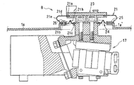
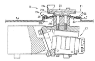
- FIG. 12 shows an example of the conventional seal structure C used for the straight-ahead feeder.
- An opening 32 is formed in the top plate 31a of the center base 31 in which the exciter 30 is housed and deployed.
- the vibration head 33 of the exciter 30 projects from the opening 32.
- a trough (not shown) of a straight-moving feeder is detachably attached to the vibrating head 33.
- the protruding vibration head 33 is covered with an annular bellows 35 as a sealing member.
- the bellows 35 is made of a flexible rubber material or the like.
- the annular upper end 35a on the upper part of the bellows 35 is connected and supported on the upper part of the vibration head 33.
- the lower annular lower end portion 35b of the bellows 35 is connected and supported by the top plate 31a, respectively.
- the vibration displacement of the vibration head 33 is allowed by the elastic deformation of the bellows 35, and the intrusion of the washing water or the like into the opening 32 is prevented.
- the trough, topcon, etc. are usually removed from the vibration head of the exciter, so there is a risk that the removed trough, etc. may be inadvertently hit against the bellows and damaged.
- a combination scale since a large number of straight feeders are arranged in close proximity in a circular shape, there is a risk of hitting a nearby bellows if the trough is not handled carefully when attaching or detaching the trough. If you hit it hard, it will crack the bellows and impair the waterproof effect.
- the bellows surface is scratched even if it does not cause cracks, the scratches may progress and lead to cracks due to repeated elastic deformation during continuous operation.
- the present invention has been made by paying attention to such a situation, and has a seal structure capable of exerting a high waterproof function even if a seal member such as a bellows is damaged, and a weighing device provided with the seal structure.
- the purpose is to provide.
- the present invention is configured as follows.
- the vibrating head of the vibrating machine is projected upward from the opening of the top plate of the housing accommodating the vibrating machine, and between the vibrating head and the top plate.
- the seal member includes an upper connecting portion connected to the upper part of the vibrating head, an intermediate connecting portion connected to the upper connecting portion and connected to the top plate, and connected to the intermediate connecting portion of the vibrating head. It is provided with a lower connecting portion connected to the lower part.
- the portion of the seal member extending from the upper connecting portion connected to the upper part of the vibration head to the intermediate connecting portion connected to the top plate is exposed to the outside, so that another object collides with the seal member. May be damaged.
- the intermediate connecting portion connected to the top plate is extended so as to be connected to the lower connecting portion connected to the lower part of the vibration head.
- the seal member is connected to the outer seal extending from the upper connecting portion connected to the upper part of the vibrating head to the intermediate connecting portion connected to the top plate, and from the intermediate connecting portion connected to the top plate to the lower part of the vibrating head.
- the infiltrated washing water, etc. is effectively prevented from entering the inside of the housing by the inner seal portion extending from the intermediate connecting portion connected to the top plate to the lower connecting portion connected to the lower part of the vibration head.
- the seal member has an outwardly bulging portion that can be curved and deformed between the upper connecting portion and the intermediate connecting portion.
- the bulging portion of the seal member between the upper connecting portion connected to the upper part of the vibrating head and the intermediate connecting portion connected to the top plate is curved and deformed with the vibration displacement of the vibrating head.
- the seal member has a bent-deformed portion that is bent and deformed between the intermediate connecting portion and the lower connecting portion.
- the bending deformation portion of the seal member between the intermediate connecting portion connected to the top plate and the lower connecting portion connected to the lower part of the vibration head is bent and deformed according to the displacement of the vibration head. Therefore, it is suppressed that the vibration of the vibration head is propagated to the top plate of the housing. Further, since the bent and deformed portion is easily deformed, the drive load of the vibration head due to the deformation resistance of the seal member becomes small.
- the bent deformed portion is a concave groove.
- the groove-shaped bent deformed portion can not only absorb the vibration but also collect the infiltrated washing water and the like. As a result, it is possible to prevent the infiltrated washing water or the like from flowing to the vibration head side.
- the sealing member is made of a transparent or translucent material.
- the degree of infiltration of cleaning water or the like into the inside of the seal member can be visually recognized from the outside. As a result, it is possible to accurately recognize whether or not washing water or the like has entered due to damage to the seal member and whether or not the seal member needs to be replaced, and maintainability is improved.
- the top plate of the housing has a partially raised raised portion, and the intermediate connecting portion of the sealing member is connected to the upper surface of the raised portion. There is.
- the seal member is arranged one step higher on the top plate.
- the upper surface of the top plate can be cleaned and wiped without touching the seal member, and the cleaning work becomes easy.
- the weighing device includes a dispersion feeder that radially disperses and conveys articles on the upper part of a center substrate as a housing, and a plurality of dispersion feeders that further convey the articles dispersed and conveyed by the dispersion feeder to the outside.
- a straight-moving feeder is provided, and a plurality of supply hoppers for temporarily holding and discharging articles from each straight-moving feeder and articles discharged from each supply hopper are held and weighted on the outer peripheral portion of the center substrate.
- the exciters of the plurality of straight feeders are housed in the center substrate, and the trough of the linear feeder is attached to the vibrating head of the vibrating machine protruding upward from the opening of the top plate of the center substrate.
- the seal structure (1) to (6) is provided with an elastically deformable annular seal member interposed between the vibration head of the vibrator of the straight-moving feeder and the top plate of the center substrate.
- the weighing device in a weighing device in which a large number of straight feeders are deployed in close proximity to each other, there are many chances that the trough hits a nearby sealing member when the trough is attached or detached.
- the sealing structure of the present invention that double-seals the inside and outside with the sealing member, even if the cleaning water or the like is infiltrated due to the damage of the sealing member, the cleaning water or the like infiltrates into the center substrate (housing). It is possible to effectively prevent this from occurring, and to perform good weighing operation without failure for a long period of time.
- the vibrating head of the exciter is housed in the center substrate and protrudes upward from the opening of the top plate of the center substrate.
- the top cone of the dispersion feeder is mounted therein, and an elastically deformable annular seal member is interposed between the vibration head of the exciter of the dispersion feeder and the top plate of the center substrate (1).
- the top cone In the weighing device in which the top cone is placed in the center of the upper part of the center base, a relatively large and heavy top cone is attached and detached by reaching out from the outer periphery of the center base, so that the top cone is dropped and the sealing member is damaged. There is a risk that it will end up.
- the sealing structure of the present invention that double-seals the inside and outside with a single sealing member, even if the washing water or the like is infiltrated due to the damage of the sealing member, the washing water or the like is provided. Can be effectively prevented from infiltrating into the center substrate (housing), and good weighing operation without failure can be performed for a long period of time.
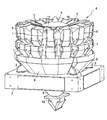
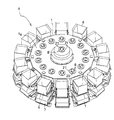
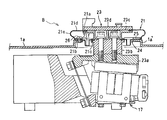
- FIG. 1 is an external perspective view of a combination scale, which is a weighing device according to an embodiment of the present invention.
- FIG. 2 is a vertical cross-sectional view showing a schematic configuration of the combination scale of FIG.
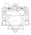
- FIG. 3 is a vertical cross-sectional view showing a removed state of the top cone of the distributed feeder and the trough of the straight feeder.
- FIG. 4 is a perspective view of the center substrate with the top cone and trough removed.
- FIG. 5 is a vertical cross-sectional view showing the seal structure of the straight feeder.
- FIG. 6 is a perspective view in which a part of the bellows as a sealing member used for the sealing structure is cut out.
- FIG. 7 is a plan view in which a part of the bellows is cut out.
- FIG. 1 is an external perspective view of a combination scale, which is a weighing device according to an embodiment of the present invention.
- FIG. 2 is a vertical cross-sectional view showing a schematic configuration of the combination scale of
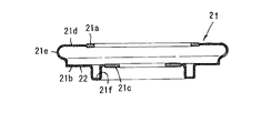
- FIG. 8 is a vertical cross-sectional view of the bellows.
- FIG. 9 is a vertical cross-sectional view showing a seal structure provided in the dispersion feeder.
- FIG. 10 is a vertical cross-sectional view showing another embodiment of the seal structure.
- FIG. 11 is a vertical cross-sectional view showing still another embodiment of the seal structure.
- FIG. 12 is a vertical cross-sectional view showing a conventional seal structure.
- FIG. 1 shows an external perspective view of the combination scale A, which is a weighing device
- FIG. 2 shows a vertical cross-sectional view showing a schematic configuration thereof.
- This combination scale A is used, for example, in a packaging line that weighs articles such as confectionery and other foods, discharges articles in a predetermined weight range into a lower packaging device (not shown), and packs them in a bag. ..
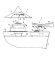
- a center base 1 as a substantially columnar housing is supported on a base 2 via a plurality of legs 3 in the center thereof.
- the base 2 has an opening that penetrates vertically through which the lower portion of the combination scale A is inserted, and is installed on the floor surface F as shown in FIG.
- the upper part of the center substrate 1 is equipped with a dispersion feeder 4 that radially disperses and conveys articles that are dropped and supplied from a supply device (not shown) by vibration. Further, around the distributed feeder 4, a plurality of (14 in this example) straight-moving feeders 5 for linearly transporting the distributed-conveyed articles outward by vibration are provided radially. Further, a supply hopper 6 and a measuring hopper 7 are provided below the end of each straight feeder 5, respectively. A plurality of (14 stations in this example) measuring units including the straight feeder 5, the supply hopper 6, and the measuring hopper 7 are arranged in a circle around the center base 1.
- a collecting chute 8 for collecting articles discharged from a plurality of measuring hoppers 7 combined and selected so as to be within a predetermined weight range is arranged.
- a funnel-shaped collective funnel 9 that collects articles that have slid down from the collective chute 8 is deployed.
- a gathering hopper 10 is provided, which temporarily receives and holds an article guided downward in the center along the gathering funnel 9, and then opens and operates based on a discharge request command from the packaging device.
- the dispersion feeder 4 includes a top cone 11 to which an article is supplied and an electromagnetic vibration exciter 12 that vibrates and drives the top cone 11.
- the exciter 12 is mounted and connected to the center of the support frame 13 arranged above the center substrate 1 via the weight sensor 14.
- the straight feeder 5 includes a gutter-shaped trough rough (feeder pan) 16 along the inward and outward directions, and an electromagnetic exciter 17 that vibrates and drives the trough rough (feeder pan) 16.
- the exciter 17 is mounted and supported on the support frame 13 in the center substrate 1 so as to surround the exciter 13 of the dispersion feeder 5.
- FIG. 3 is a vertical cross-sectional view showing a removed state of the top cone 11 of the distributed feeder 4 and the trough 16 of the straight-ahead feeder 5, and
- FIG. 4 is a perspective view of the center substrate 1 from which the top cone 11 and the trough 16 have been removed. ..
- the dispersion feeder 4 positions and engages the buckle-type connector 15 provided inside the top cone 11 with the exposed upper end of the exciter 12, and swings the operating lever 15a up and down over the dead center. Then, the top cone 11 can be tightened and connected to the exciter 12, or can be removed from the exciter 12.
- the straight-ahead feeder 5 positions and engages a buckle-type connector 18 provided on the lower surface of the bottom of the trough 16 with the exposed upper end of the exciter 17, and swings the operating lever 18a up and down over the dead center. Then, the trough 16 can be tightened and connected to the exciter 17, or can be removed from the exciter 17.
- a drive unit 19 such as a drive device for opening and closing the gates of the supply hopper 6 and the measuring hopper 7 is housed in the outer peripheral portion of the center substrate 1. Further, a weight sensor such as a load cell that measures the weight of an article in each measuring hopper 7 is also housed in the center substrate 1 together with the drive unit 19.
- the weight of the article placed on the top cone 11 is detected by the weight sensor 14, and the amount of articles supplied to the distributed feeder 4 so that the article within a certain weight range exists on the top cone 11. Is controlled.
- a seal structure B is provided at the attachment portion of the dispersion feeder 4 and the straight feeder 5 so that the washing water or the like does not enter the inside of the center substrate 1.
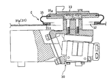
- FIG. 5 is a vertical cross-sectional view showing the seal structure B of the straight feeder 5
- FIG. 6 is a perspective view in which a part of a bellows as a seal member used for the seal structure B is cut out.
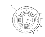
- FIG. 7 is a plan view in which a part of the bellows is cut out
- FIG. 8 is a vertical sectional view of the bellows.
- annular bellows 21 made of a transparent rubber material such as silicon rubber, which is easily elastically deformed, is used as the seal member.
- the bellows 21 includes an annular upper connecting portion 21a connected to the upper part of the vibration head 23, an annular intermediate connecting portion 21b connected to the upper connecting portion 21a and connected to the top plate 1a of the center substrate 1, and the annular intermediate connecting portion 21b. It is provided with an annular lower connecting portion 21c that is connected to the intermediate connecting portion 21b and connected to the lower part of the vibration head 23.
- the upper connecting portion 21a is formed thickly on the edge of the annular bellows 12 on the upper center (upper inward) side.
- the lower connecting portion 21c is formed thickly on the edge of the bellows 21 on the lower center (lower inward) side.
- the intermediate connecting portion 21b is formed in a flat shape along the top plate 1a of the center substrate 1.
- a plurality of (five in this example) connecting holes 22 for connecting the center substrate 1 to the top plate 1a are formed at a constant pitch along the circumferential direction.
- a bulging portion 21e that is curved and bulged outward and is easily elastically deformed is provided. It is formed in a ring shape.
- the intermediate connecting portion 21b extends from the lower portion of the bulging portion 21e toward the center (inward) side of the annular bellows 21, and the bending between the intermediate connecting portion 21b and the lower connecting portion 21c is easily elastically deformed.
- the concave groove 21f as a deformed portion is formed in an annular shape.
- the vibrating machine 17 is provided with a vibrating head 23 that is electromagnetically driven and vibrates and displaces.
- the trough mounting portion of the top plate 1a of the center substrate 1 is formed to be raised one step higher to form the top plate raised portion 1a'.
- the vibration head 23 projects upward from the opening 24 formed on the upper surface of the top plate raised portion 1a'.
- the vibrating head 23 is connected on a vibrating body 23a that is electromagnetically driven and vibrated at a predetermined frequency and amplitude, a first support member 23b that is connected on the vibrating body 23a, and a first support member 23b. It includes a second support member 23c and an engagement connecting member 23d provided on the second support member 23c.
- the lower connecting portion 21c of the bellows 21 is sandwiched and connected between the first support member 23b and the second support member 23c.
- the upper connecting portion 21a of the bellows 21 is sandwiched and connected between the second support member 23c and the engaging connecting portion 23d.
- the intermediate connecting portion 21b of the bellows 21 is sandwiched between the pressing ring 25 incorporated in the bellows 21 and the upper surface of the top plate raised portion 1a'.
- the bulging portion 21e of the bellows 21 elastically deforms with the vibration displacement of the vibration head 23, so that the vibration of the vibration head 23 is absorbed and the vibration to the top plate 1a. Propagation is suppressed.
- the vibration of the vibration head 23 is also absorbed by the elastic deformation of the concave groove 21f due to the vibration displacement of the vibration head 23.
- the seal structure B the intermediate connecting portion 21b connected to the top plate raised portion 1a'extends to the lower connecting portion 21c connected to the lower part of the vibration head 23 via the concave groove 21f.
- the outer seal is formed by the upper surface portion 21d, the bulging portion 21e, and the portion extending from the bulging portion 21a to the intermediate connecting portion 21b that are exposed to the outside, while the concave groove 21f is formed from the intermediate connecting portion 21b.
- An inner seal is formed by a portion reaching the lower connecting portion 21c via the lower connecting portion 21c. That is, the inner and outer double seals are made.
- the infiltrated washing water can be removed by the inner seal extending from the intermediate connecting portion 21b to the lower connecting portion 21c through the concave groove 21f. , It is possible to prevent the inflow to the inside of the center substrate 1. Further, the washing water that has entered the bellows 21 will be stored in the recessed groove 21g.
- the bellows 21 is made of a transparent rubber material and the inside can be easily visually recognized, it is possible to timely monitor whether or not washing water or the like has accumulated in the concave groove 21 g. Thereby, it is possible to determine whether or not the bellows 21 is damaged and whether or not the bellows needs to be replaced.
- the bellows is not limited to silicone rubber, and may be made of a translucent material such as EPDM.
- the seal structure B can also be used for waterproofing the distributed feeder 4, and FIG. 9 shows a state in which the distributed feeder 4 is provided in the mounting portion.
- a top plate raised portion 1a'composed of another member is provided so as to project greatly upward.
- the vibration head 27 of the exciter 12 arranged inside the top plate raised portion 1a' projects upward from the opening at the center of the upper surface of the top plate raised portion 1a'.
- a top cone 11 is detachably connected to the upper end of the vibration head 27 via a buckle-type connector 15.
- a bellows 21 having the same specifications as that used for the seal structure B of the straight feeder 5 is formed in the same manner as in the case of the straight feeder 5. It is attached to form the seal structure B.
- a ridge 21h that rises upward as a bending deformation portion may be formed between the intermediate connecting portion 21b and the lower connecting portion 21c of the bellows 21.
- the intermediate connecting portion 21b of the bellows 21 is tilted so as to rise toward the lower connecting portion 21c, and the washing water or the like that has penetrated into the bellows 21 reaches the lower connecting portion 21c. It can also be carried out in a form of suppressing the flow.
- the seal structure according to the present invention can also be used as a seal structure for a straight-moving feeder in a combination scale in which multiple measuring units are arranged in a horizontal row instead of being arranged in a circle as described above.
- the seal structure according to the present invention can also be used simply as a waterproof means for an article conveying device that vibrates and conveys an article with a straight feeder.
Landscapes
- Physics & Mathematics (AREA)
- General Physics & Mathematics (AREA)
- Engineering & Computer Science (AREA)
- Mechanical Engineering (AREA)
- Jigging Conveyors (AREA)
- Feeding Of Articles To Conveyors (AREA)
Abstract
Description
前記シール部材は、前記振動ヘッドの上部に連結される上方連結部と、該上方連結部に連なって前記天板に連結される中間連結部と、該中間連結部に連なって、前記振動ヘッドの下部に連結される下方連結部とを備える。
前記複数の直進フィーダの加振機が、前記センター基体に収容され、該センター基体の天板の開口から上方へ突出した前記加振機の振動ヘッドに、前記直進フィーダのトラフが装着され、前記直進フィーダの加振機の振動ヘッドと前記センター基体の天板との間に、弾性変形可能な環状のシール部材を介在させた上記(1)ないし(6)のシール構造を備えている。
本発明は、以下のような形態で実施することもできる。
1a 天板
1a´ 天板隆起部
4 分散フィーダ
5 直進フィーダ
6 供給ホッパ
7 計量ホッパ
11 トップコーン
12 加振機
23 振動ヘッド
16 トラフ
17 加振機
21 ベローズ(シール部材)
21a 上方連結部
21b 中間連結部
21c 下方連結部
21d 上面部
21e 膨出部
21f 凹溝(屈曲変形部)
23 振動ヘッド
A 計量装置(組合せ秤)
B シール構造
Claims (12)
- 加振機を収容した筐体の天板の開口から、前記加振機の振動ヘッドを上方に突出させ、前記振動ヘッドと前記天板との間に、弾性変形可能な環状のシール部材を介在させたシール構造であって、
前記シール部材は、前記振動ヘッドの上部に連結される上方連結部と、該上方連結部に連なって前記天板に連結される中間連結部と、該中間連結部に連なって、前記振動ヘッドの下部に連結される下方連結部とを備える、
シール構造。 - 前記シール部材は、前記上方連結部と前記中間連結部との間に、湾曲変形可能な外方へ膨出した膨出部を有する、
請求項1に記載のシール構造。 - 前記シール部材は、前記中間連結部と前記下方連結部との間に、屈曲変形した屈曲変形部を有する、
請求項1に記載のシール構造。 - 前記シール部材は、前記中間連結部と前記下方連結部との間に、屈曲変形した屈曲変形部を有する、
請求項2に記載のシール構造。 - 前記屈曲変形部が凹溝である、
請求項3記載のシール構造。 - 前記屈曲変形部が凹溝である、
請求項4記載のシール構造。 - 前記シール部材は、透明又は半透明材料で構成されている、
請求項1ないし6のいずれか一項に記載のシール構造。 - 前記筐体の前記天板は、部分的に隆起した隆起部を有し、該隆起部の上面に、前記シール部材の前記中間連結部が連結されている、
請求項1ないし6のいずれか一項に記載のシール構造。 - 筐体としてのセンター基体の上部に、物品を放射状に分散搬送する分散フィーダと、該分散フィーダで分散搬送された物品を更に外方に搬送する複数の直進フィーダとが設けられ、前記センター基体の外周部に、各直進フィーダからの物品を一時保持して排出する複数の供給ホッパと、各供給ホッパから排出された物品を保持して、その重量を計量する複数の計量ホッパとが設けられた計量装置であって、
前記複数の直進フィーダの加振機が、前記センター基体に収容され、該センター基体の天板の開口から上方へ突出した前記加振機の振動ヘッドに、前記直進フィーダのトラフが装着され、
前記直進フィーダの加振機の振動ヘッドと前記センター基体の天板との間に、弾性変形可能な環状のシール部材を介在させた前記請求項7に記載のシール構造を備える、
計量装置。 - 前記分散フィーダの加振機が、前記センター基体に収容され、該センター基体の天板の開口から上方へ突出した前記加振機の振動ヘッドに、前記分散フィーダのトップコーンが装着され、
前記分散フィーダの加振機の振動ヘッドと前記センター基体の前記天板との間に、弾性変形可能な環状のシール部材を介在させた前記請求項7に記載のシール構造を備える、
請求項9に記載の計量装置。 - 筐体としてのセンター基体の上部に、物品を放射状に分散搬送する分散フィーダと、該分散フィーダで分散搬送された物品を更に外方に搬送する複数の直進フィーダとが設けられ、前記センター基体の外周部に、各直進フィーダからの物品を一時保持して排出する複数の供給ホッパと、各供給ホッパから排出された物品を保持して、その重量を計量する複数の計量ホッパとが設けられた計量装置であって、
前記複数の直進フィーダの加振機が、前記センター基体に収容され、該センター基体の天板の開口から上方へ突出した前記加振機の振動ヘッドに、前記直進フィーダのトラフが装着され、
前記直進フィーダの加振機の振動ヘッドと前記センター基体の天板との間に、弾性変形可能な環状のシール部材を介在させた前記請求項8に記載のシール構造を備える、
計量装置。 - 前記分散フィーダの加振機が、前記センター基体に収容され、該センター基体の天板の開口から上方へ突出した前記加振機の振動ヘッドに、前記分散フィーダのトップコーンが装着され、
前記分散フィーダの加振機の振動ヘッドと前記センター基体の前記天板との間に、弾性変形可能な環状のシール部材を介在させた前記請求項8に記載のシール構造を備える、
請求項11に記載の計量装置。
Priority Applications (5)
| Application Number | Priority Date | Filing Date | Title |
|---|---|---|---|
| PCT/JP2020/010785 WO2021181602A1 (ja) | 2020-03-12 | 2020-03-12 | シール構造及びそれを備えた計量装置 |
| EP20924935.8A EP4119471B1 (en) | 2020-03-12 | 2020-03-12 | Seal structure and weighing machine comprising same |
| JP2022507110A JP7332269B2 (ja) | 2020-03-12 | 2020-03-12 | シール構造及びそれを備えた計量装置 |
| CN202080097992.8A CN115210154B (zh) | 2020-03-12 | 2020-03-12 | 密封结构及具备该密封结构的计量装置 |
| US17/910,249 US12351395B2 (en) | 2020-03-12 | 2020-03-12 | Seal structure and weighing machine comprising same |
Applications Claiming Priority (1)
| Application Number | Priority Date | Filing Date | Title |
|---|---|---|---|
| PCT/JP2020/010785 WO2021181602A1 (ja) | 2020-03-12 | 2020-03-12 | シール構造及びそれを備えた計量装置 |
Publications (1)
| Publication Number | Publication Date |
|---|---|
| WO2021181602A1 true WO2021181602A1 (ja) | 2021-09-16 |
Family
ID=77671459
Family Applications (1)
| Application Number | Title | Priority Date | Filing Date |
|---|---|---|---|
| PCT/JP2020/010785 Ceased WO2021181602A1 (ja) | 2020-03-12 | 2020-03-12 | シール構造及びそれを備えた計量装置 |
Country Status (5)
| Country | Link |
|---|---|
| US (1) | US12351395B2 (ja) |
| EP (1) | EP4119471B1 (ja) |
| JP (1) | JP7332269B2 (ja) |
| CN (1) | CN115210154B (ja) |
| WO (1) | WO2021181602A1 (ja) |
Families Citing this family (2)
| Publication number | Priority date | Publication date | Assignee | Title |
|---|---|---|---|---|
| EP3879246B1 (en) * | 2020-03-10 | 2023-09-13 | Ishida Co., Ltd. | Conveyance mechanism and combination weighing apparatus |
| JP2022125749A (ja) * | 2021-02-17 | 2022-08-29 | 株式会社イシダ | 組合せ計量装置 |
Citations (2)
| Publication number | Priority date | Publication date | Assignee | Title |
|---|---|---|---|---|
| JPS5751063A (en) * | 1980-09-11 | 1982-03-25 | Iseki & Co Ltd | Dustboot for cabin |
| JP2014235141A (ja) | 2013-06-05 | 2014-12-15 | 大和製衡株式会社 | 組合せ秤 |
Family Cites Families (19)
| Publication number | Priority date | Publication date | Assignee | Title |
|---|---|---|---|---|
| JPS54180120U (ja) | 1978-06-09 | 1979-12-20 | ||
| JPS5885529A (ja) * | 1981-11-18 | 1983-05-21 | Nec Corp | 半導体装置の製造方法 |
| JPS5885529U (ja) | 1981-12-08 | 1983-06-10 | 日産車体株式会社 | シフトレバ−ブ−ツ |
| EP0362567B1 (en) * | 1988-09-07 | 1992-12-09 | Ishida Scales Mfg. Co., Ltd. | Waterproof automatic weighing apparatus |
| JPH0551820U (ja) * | 1991-12-20 | 1993-07-09 | アンリツ株式会社 | 分散供給装置 |
| JP3485630B2 (ja) * | 1994-04-15 | 2004-01-13 | 株式会社イシダ | 加振式搬送装置のトラフ取り付け構造 |
| DE19617821C2 (de) * | 1996-05-03 | 1998-07-16 | Multipond Waegetechnik Gmbh | Kombinationswaage |
| JP3836351B2 (ja) * | 2001-10-09 | 2006-10-25 | 株式会社イシダ | 計量装置および組合せ計量装置 |
| JP2006116602A (ja) * | 2004-09-24 | 2006-05-11 | Bondotekku:Kk | 加圧装置の平行調整方法及び装置 |
| JP2008298716A (ja) * | 2007-06-04 | 2008-12-11 | Ishida Co Ltd | 計量装置の洗浄方法、計量装置、計量包装装置および計量包装検査システム |
| JP2009235971A (ja) * | 2008-03-26 | 2009-10-15 | Mitsubishi Heavy Ind Ltd | シール部材、蒸気タービン及び共振回避方法 |
| WO2010113932A1 (ja) * | 2009-03-31 | 2010-10-07 | イーグル工業株式会社 | ベローズ型メカニカルシール |
| JP2011163957A (ja) * | 2010-02-10 | 2011-08-25 | Yamato Scale Co Ltd | 扉の防水構造および計量装置 |
| JP3174285U (ja) * | 2011-10-17 | 2012-03-15 | 株式会社イシダ | 防水構造物および組合計量装置 |
| JP6050690B2 (ja) * | 2013-01-21 | 2016-12-21 | 株式会社イシダ | 組合せ計量装置 |
| JP6086759B2 (ja) * | 2013-03-05 | 2017-03-01 | 大和製衡株式会社 | ロードセル |
| DE102013105647B4 (de) * | 2013-05-31 | 2014-12-11 | Wipotec Wiege- Und Positioniersysteme Gmbh | Gehäuse für eine Wägevorrichtung |
| CN203385476U (zh) * | 2013-08-26 | 2014-01-08 | 佛山市顺力德智能机器有限公司 | 一种组合秤中振动头与机箱之间的防水结构 |
| JP2015068721A (ja) * | 2013-09-30 | 2015-04-13 | 株式会社イシダ | 計量ユニット |
-
2020
- 2020-03-12 WO PCT/JP2020/010785 patent/WO2021181602A1/ja not_active Ceased
- 2020-03-12 US US17/910,249 patent/US12351395B2/en active Active
- 2020-03-12 EP EP20924935.8A patent/EP4119471B1/en active Active
- 2020-03-12 CN CN202080097992.8A patent/CN115210154B/zh active Active
- 2020-03-12 JP JP2022507110A patent/JP7332269B2/ja active Active
Patent Citations (2)
| Publication number | Priority date | Publication date | Assignee | Title |
|---|---|---|---|---|
| JPS5751063A (en) * | 1980-09-11 | 1982-03-25 | Iseki & Co Ltd | Dustboot for cabin |
| JP2014235141A (ja) | 2013-06-05 | 2014-12-15 | 大和製衡株式会社 | 組合せ秤 |
Non-Patent Citations (1)
| Title |
|---|
| See also references of EP4119471A4 |
Also Published As
| Publication number | Publication date |
|---|---|
| US12351395B2 (en) | 2025-07-08 |
| EP4119471A1 (en) | 2023-01-18 |
| JPWO2021181602A1 (ja) | 2021-09-16 |
| US20230091619A1 (en) | 2023-03-23 |
| CN115210154A (zh) | 2022-10-18 |
| EP4119471B1 (en) | 2024-07-17 |
| CN115210154B (zh) | 2024-08-09 |
| JP7332269B2 (ja) | 2023-08-23 |
| EP4119471A4 (en) | 2023-11-29 |
Similar Documents
| Publication | Publication Date | Title |
|---|---|---|
| JP5406381B2 (ja) | 組合せ秤 | |
| WO2021181602A1 (ja) | シール構造及びそれを備えた計量装置 | |
| EP3214908B1 (en) | Article handling device | |
| EP3196611B1 (en) | Combination weighing device | |
| JP7403934B2 (ja) | ホッパ取付け構造及びそれを備えた計量装置 | |
| JP6034652B2 (ja) | 組合せ計量装置 | |
| JP6242086B2 (ja) | 組合せ秤 | |
| CN210145974U (zh) | 一种带有固体物料计量功能的多肽合成釜 | |
| CN113252154B (zh) | 组合秤 | |
| EP4700339A1 (en) | Waterproof structure of combination weighing device | |
| CN214134745U (zh) | 一种酸奶杯盖自动组装用的酸奶勺提升机 | |
| EP4700340A1 (en) | Waterproof structure of combination weighing apparatus | |
| JP3836351B2 (ja) | 計量装置および組合せ計量装置 | |
| JP7692668B2 (ja) | 組合せ秤 | |
| JP7812190B2 (ja) | 組合せ計量装置の防水構造 | |
| JP2020143906A (ja) | 直進フィーダ用のトラフ及びこれを備えた組合せ秤 | |
| CN218464687U (zh) | 一种新型球形散装食品下料装置 | |
| JP7537854B2 (ja) | ホッパ及び組合せ秤 | |
| JP2006038720A (ja) | 組合せ秤 | |
| JP6714054B2 (ja) | 物品処理装置 | |
| JP2503733Y2 (ja) | 組合せ計量装置 | |
| JP2021148540A (ja) | 計量機構 | |
| CN110803493A (zh) | 一种称重上料装置 | |
| CN118419424A (zh) | 一种密胺粉料料仓 | |
| JP2006038719A (ja) | 組合せ秤 |
Legal Events
| Date | Code | Title | Description |
|---|---|---|---|
| 121 | Ep: the epo has been informed by wipo that ep was designated in this application |
Ref document number: 20924935 Country of ref document: EP Kind code of ref document: A1 |
|
| ENP | Entry into the national phase |
Ref document number: 2022507110 Country of ref document: JP Kind code of ref document: A |
|
| NENP | Non-entry into the national phase |
Ref country code: DE |
|
| ENP | Entry into the national phase |
Ref document number: 2020924935 Country of ref document: EP Effective date: 20221012 |
|
| WWG | Wipo information: grant in national office |
Ref document number: 17910249 Country of ref document: US |
|
| WWG | Wipo information: grant in national office |
Ref document number: 202227051484 Country of ref document: IN |