WO2021181619A1 - 電池モジュール及び電池システム - Google Patents
電池モジュール及び電池システム Download PDFInfo
- Publication number
- WO2021181619A1 WO2021181619A1 PCT/JP2020/010876 JP2020010876W WO2021181619A1 WO 2021181619 A1 WO2021181619 A1 WO 2021181619A1 JP 2020010876 W JP2020010876 W JP 2020010876W WO 2021181619 A1 WO2021181619 A1 WO 2021181619A1
- Authority
- WO
- WIPO (PCT)
- Prior art keywords
- battery
- metal plate
- case
- base
- battery group
- Prior art date
- Legal status (The legal status is an assumption and is not a legal conclusion. Google has not performed a legal analysis and makes no representation as to the accuracy of the status listed.)
- Ceased
Links
Images




Classifications
-
- H—ELECTRICITY
- H01—ELECTRIC ELEMENTS
- H01M—PROCESSES OR MEANS, e.g. BATTERIES, FOR THE DIRECT CONVERSION OF CHEMICAL ENERGY INTO ELECTRICAL ENERGY
- H01M10/00—Secondary cells; Manufacture thereof
- H01M10/60—Heating or cooling; Temperature control
- H01M10/65—Means for temperature control structurally associated with the cells
- H01M10/655—Solid structures for heat exchange or heat conduction
- H01M10/6556—Solid parts with flow channel passages or pipes for heat exchange
-
- H—ELECTRICITY
- H01—ELECTRIC ELEMENTS
- H01M—PROCESSES OR MEANS, e.g. BATTERIES, FOR THE DIRECT CONVERSION OF CHEMICAL ENERGY INTO ELECTRICAL ENERGY
- H01M10/00—Secondary cells; Manufacture thereof
- H01M10/60—Heating or cooling; Temperature control
- H01M10/61—Types of temperature control
- H01M10/613—Cooling or keeping cold
-
- H—ELECTRICITY
- H01—ELECTRIC ELEMENTS
- H01M—PROCESSES OR MEANS, e.g. BATTERIES, FOR THE DIRECT CONVERSION OF CHEMICAL ENERGY INTO ELECTRICAL ENERGY
- H01M10/00—Secondary cells; Manufacture thereof
- H01M10/60—Heating or cooling; Temperature control
- H01M10/65—Means for temperature control structurally associated with the cells
- H01M10/655—Solid structures for heat exchange or heat conduction
- H01M10/6554—Rods or plates
-
- H—ELECTRICITY
- H01—ELECTRIC ELEMENTS
- H01M—PROCESSES OR MEANS, e.g. BATTERIES, FOR THE DIRECT CONVERSION OF CHEMICAL ENERGY INTO ELECTRICAL ENERGY
- H01M50/00—Constructional details or processes of manufacture of the non-active parts of electrochemical cells other than fuel cells, e.g. hybrid cells
- H01M50/10—Primary casings; Jackets or wrappings
- H01M50/102—Primary casings; Jackets or wrappings characterised by their shape or physical structure
- H01M50/103—Primary casings; Jackets or wrappings characterised by their shape or physical structure prismatic or rectangular
-
- H—ELECTRICITY
- H01—ELECTRIC ELEMENTS
- H01M—PROCESSES OR MEANS, e.g. BATTERIES, FOR THE DIRECT CONVERSION OF CHEMICAL ENERGY INTO ELECTRICAL ENERGY
- H01M50/00—Constructional details or processes of manufacture of the non-active parts of electrochemical cells other than fuel cells, e.g. hybrid cells
- H01M50/10—Primary casings; Jackets or wrappings
- H01M50/116—Primary casings; Jackets or wrappings characterised by the material
- H01M50/117—Inorganic material
- H01M50/119—Metals
-
- H—ELECTRICITY
- H01—ELECTRIC ELEMENTS
- H01M—PROCESSES OR MEANS, e.g. BATTERIES, FOR THE DIRECT CONVERSION OF CHEMICAL ENERGY INTO ELECTRICAL ENERGY
- H01M50/00—Constructional details or processes of manufacture of the non-active parts of electrochemical cells other than fuel cells, e.g. hybrid cells
- H01M50/20—Mountings; Secondary casings or frames; Racks, modules or packs; Suspension devices; Shock absorbers; Transport or carrying devices; Holders
- H01M50/204—Racks, modules or packs for multiple batteries or multiple cells
- H01M50/207—Racks, modules or packs for multiple batteries or multiple cells characterised by their shape
- H01M50/209—Racks, modules or packs for multiple batteries or multiple cells characterised by their shape adapted for prismatic or rectangular cells
-
- H—ELECTRICITY
- H01—ELECTRIC ELEMENTS
- H01M—PROCESSES OR MEANS, e.g. BATTERIES, FOR THE DIRECT CONVERSION OF CHEMICAL ENERGY INTO ELECTRICAL ENERGY
- H01M2220/00—Batteries for particular applications
- H01M2220/20—Batteries in motive systems, e.g. vehicle, ship, plane
-
- Y—GENERAL TAGGING OF NEW TECHNOLOGICAL DEVELOPMENTS; GENERAL TAGGING OF CROSS-SECTIONAL TECHNOLOGIES SPANNING OVER SEVERAL SECTIONS OF THE IPC; TECHNICAL SUBJECTS COVERED BY FORMER USPC CROSS-REFERENCE ART COLLECTIONS [XRACs] AND DIGESTS
- Y02—TECHNOLOGIES OR APPLICATIONS FOR MITIGATION OR ADAPTATION AGAINST CLIMATE CHANGE
- Y02E—REDUCTION OF GREENHOUSE GAS [GHG] EMISSIONS, RELATED TO ENERGY GENERATION, TRANSMISSION OR DISTRIBUTION
- Y02E60/00—Enabling technologies; Technologies with a potential or indirect contribution to GHG emissions mitigation
- Y02E60/10—Energy storage using batteries
Definitions
- Embodiments of the present invention relate to battery modules and battery systems.
- a group of batteries equipped with a plurality of batteries (cells) is stored in the storage space of the case.
- a metal plate is provided to dissipate heat from the metal plate.
- a plastic member is brought into close contact with each of the battery group and the metal plate. Then, heat is transferred from the battery group to the metal plate through the member having plasticity, and the heat transferability from the battery group to the metal plate is improved.
- an insulating material having an electrical insulating property is used as the above-mentioned plastic member.
- the problem to be solved by the present invention is a battery module and a battery in which charging of the metal plate and discharge from the metal plate are effectively prevented in a configuration in which a metal plate that dissipates heat transmitted from the battery group to the outside is provided. To provide the system.
- the battery module includes a battery group, a case, a metal plate, an insulator, and an electrical connection path.
- the battery group includes a plurality of batteries, and each of the plurality of batteries includes an electrode group and a metal outer container in which the electrode group is housed.
- the case is provided with a case peripheral wall that surrounds the storage space of the battery group, and has electrical insulation.
- the metal plate is provided between the battery group and the base, and has a clearance between the base and the metal plate.
- the insulating material has plasticity and electrical insulation, and is sandwiched between the battery group and the metal plate.
- the outer container of each of the plurality of batteries and the metal plate are electrically insulated by an insulating material.
- the electrical connection path electrically connects the metal plate to the base.
- the battery system comprises the battery module described above and a metal base. A battery module is installed on the base with a metal plate located between the battery group and the base.
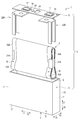
- FIG. 1 is a perspective view schematically showing an example of a single battery used in the battery module according to the embodiment.
- FIG. 2 is a perspective view showing a battery module provided in the battery system according to the first embodiment.
- FIG. 3 is a perspective view showing the battery module of FIG. 2 in a state where a part of the case is omitted.
- FIG. 4 is a perspective view showing a part of the case of the battery module of FIG.
- FIG. 5 is a perspective view showing the battery module of FIG. 2 in an exploded manner for each member.
- FIG. 6 is a cross-sectional view schematically showing the battery system according to the first embodiment.
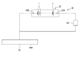
- FIG. 7 is a schematic view showing an example of the circuit configuration of the battery system according to the first embodiment.
- FIG. 1 is a perspective view schematically showing an example of a single battery used in the battery module according to the embodiment.
- FIG. 2 is a perspective view showing a battery module provided in the battery system according to the first embodiment.
- FIG. 3 is
- FIG. 8 is a cross-sectional view schematically showing a configuration of an electrical connection path and its vicinity in the battery system according to the first embodiment.
- FIG. 9 is a cross-sectional view schematically showing the configuration of an electrical connection path and its vicinity in a battery system according to a modified example.
- the battery system includes a base and a battery module installed on the base.
- a battery group including a plurality of batteries (cells) is mounted on the battery module.
- the batteries constituting the battery group are, for example, secondary batteries such as a lithium ion secondary battery.
- FIG. 1 shows an example of a single battery 1.
- the battery 1 includes an electrode group 2 and an outer container 3 in which the electrode group 2 is housed.
- the outer container 3 is formed of a metal such as aluminum, aluminum alloy, iron or stainless steel.
- the outer container 3 includes a container body 5 and a lid 6.
- the vertical direction (direction indicated by arrow X1 and arrow X2) and the horizontal direction (vertical or substantially vertical) intersecting the vertical direction (direction indicated by arrow Y1 and arrow Y2).
- the height directions (directions indicated by arrows Z1 and Z2) that intersect (vertically or substantially vertical) with respect to both the vertical and horizontal directions are defined.
- the dimensions in the vertical direction are much smaller than the dimensions in the horizontal direction and the dimensions in the height direction.
- the container body 5 includes a bottom wall 7 and a peripheral wall 8.
- the internal cavity 10 in which the electrode group 2 is housed is defined by the bottom wall 7 and the peripheral wall 8.
- the internal cavity 10 opens in the height direction toward the side opposite to the side where the bottom wall 7 is located.
- the peripheral wall 8 includes two pairs of side walls 11 and 12.
- the pair of side walls 11 face each other with the internal cavity 10 interposed therebetween in the lateral direction.
- the pair of side walls 12 face each other with the internal cavity 10 interposed therebetween in the vertical direction.
- Each of the side walls 11 extends continuously along the longitudinal direction between the side walls 12.
- Each of the side walls 12 extends continuously along the lateral direction between the side walls 11.
- the lid 6 is attached to the container body 5 at the opening of the internal cavity 10. Therefore, the lid 6 is attached to the peripheral wall 8 at the end opposite to the bottom wall 7.
- the lid 6 and the bottom wall 7 face each other with the internal cavity 10 interposed therebetween in the height direction.
- the electrode group 2 is formed in a flat shape, for example, and includes a positive electrode 15 and a negative electrode 16. Further, in the electrode group 2, a separator (not shown) is interposed between the positive electrode 15 and the negative electrode 16. The separator is formed of a material having electrical insulating properties, and electrically insulates the positive electrode 15 from the negative electrode 16.
- the positive electrode 15 includes a positive electrode current collector 15A such as a positive electrode current collector foil, and a positive electrode active material-containing layer (not shown) supported on the surface of the positive electrode current collector 15A.
- the positive electrode current collector 15A is not limited to these, but is, for example, an aluminum foil or an aluminum alloy foil, and has a thickness of about 10 ⁇ m to 20 ⁇ m.
- the positive electrode active material-containing layer includes a positive electrode active material, and may optionally contain a binder and a conductive agent. Examples of the positive electrode active material include, but are not limited to, oxides, sulfides, polymers, and the like that can occlude and release lithium ions.
- the positive electrode current collector 15A includes a positive electrode current collector tab 15B as a portion in which the positive electrode active material-containing layer is not supported.
- the negative electrode 16 includes a negative electrode current collector 16A such as a negative electrode current collector foil, and a negative electrode active material-containing layer (not shown) supported on the surface of the negative electrode current collector 16A.
- the negative electrode current collector 16A is not limited to these, but is, for example, an aluminum foil, an aluminum alloy foil, a copper foil, or the like, and has a thickness of about 10 ⁇ m to 20 ⁇ m.
- the negative electrode active material-containing layer includes a negative electrode active material, and may optionally contain a binder and a conductive agent.
- the negative electrode active material is not particularly limited, and examples thereof include metal oxides, metal sulfides, metal nitrides, and carbon materials capable of occluding and releasing lithium ions.
- the negative electrode current collector 16A includes a negative electrode current collector tab 16B as a portion in which the negative electrode active material-containing layer is not supported.
- the positive electrode current collecting tab 15B protrudes with respect to the negative electrode 16. Then, the negative electrode current collecting tab 16B projects to the positive electrode 15 in the direction opposite to the protruding direction of the positive electrode current collecting tab 15B.
- the electrode group 2 is arranged so that the positive electrode current collecting tab 15B projects laterally to one side with respect to the negative electrode 16. Then, in the electrode group 2, the negative electrode current collecting tab 16B protrudes with respect to the positive electrode 15 in the lateral direction of the battery 1 to the side opposite to the side on which the positive electrode current collecting tab 15B protrudes.
- an electrolytic solution (not shown) is held (impregnated) in the electrode group 2.
- the electrolytic solution may be a non-aqueous electrolytic solution in which an electrolyte is dissolved in an organic solvent, or an aqueous electrolytic solution such as an aqueous solution.
- a gel-like electrolyte may be used, or a solid electrolyte may be used.
- the solid electrolyte is interposed between the positive electrode 15 and the negative electrode 16 instead of the separator. In this case, the solid electrolyte electrically insulates the positive electrode 15 from the negative electrode 16.
- a pair of electrode terminals 17 are attached to the outer surface (upper surface) of the lid 6 of the outer container 3.
- the electrode terminal 17 is formed of a conductive material such as metal.
- One of the electrode terminals 17 is the positive electrode terminal of the battery 1, and the other of the electrode terminals 17 is the negative electrode terminal of the battery 1.
- An insulating member 18 is provided between each of the electrode terminals 17 and the lid 6.
- Each of the electrode terminals 17 is electrically insulated from the outer container 3 including the lid 6 by the insulating member 18.
- the positive electrode current collecting tab 15B of the electrode group 2 is electrically connected to the corresponding positive electrode terminal of the electrode terminal 17 via one or more positive electrode leads such as the backup lead 21A and the lead 22A.
- the negative electrode current collecting tab 16B of the electrode group 2 is electrically connected to the corresponding negative electrode terminal of the electrode terminal 17 via one or more negative electrode leads such as the backup lead 21B and the lead 22B. ..
- Each of the positive electrode lead and the negative electrode lead is formed of a conductive material such as metal.
- each of the positive electrode current collecting tab 15B and the positive electrode lead is electrically connected to the outer container 3 (container body 5 and lid 6) by one or more insulating members (not shown). Is insulated.
- each of the negative electrode current collecting tab 16B and the negative electrode lead is electrically insulated from the outer container 3 by one or more insulating members (not shown).
- a gas release valve 23 and a liquid injection port are formed on the lid 6. Then, a sealing plate 25 that closes the liquid injection port is welded to the outer surface of the lid 6.
- the gas release valve 23, the liquid injection port, and the like do not have to be provided in the battery.
- the outer container 3 has the potential (positive electrode potential) of the positive electrode terminal (corresponding one of 17) and the negative electrode terminal due to conduction through the electrolytic solution or the like. It may be a potential between the potential (negative electrode potential).
- the battery system includes a battery module and a base on which the battery module is installed.
- the battery module includes a battery group, and the battery group includes a plurality of batteries (cell cells).
- the plurality of batteries constituting the battery group have, for example, the same configuration as the above-mentioned battery 1.
- the battery module 31 includes a battery group 32 and a case 33 in which the battery group 32 is housed.
- the case 33 defines the storage space 35 for the battery group 32.
- the battery group 32 includes a plurality of the above-mentioned batteries (cell cells) 1, and in the battery group 32, the plurality of batteries 1 are electrically connected via a bus bar (not shown) or the like.
- a series connection structure in which a plurality of batteries 1 are electrically connected in series
- a parallel connection structure in which a plurality of batteries 1 are electrically connected in parallel are formed.
- the case 33 is formed of a material having electrical insulation. Examples of the material forming the case 33 include resins such as polyphenylene ether, polycarbonate and polybutylene terephthalate. In one example of FIGS. 2 and 3, the case 33 is formed of a plurality of members including the case member 36. In FIG. 3, parts other than the case member 36 in the case 33 are omitted.
- the vertical direction (directions indicated by arrows X3 and X4) and the horizontal direction (vertical or substantially vertical) intersecting the vertical direction (arrows Y3 and arrows).
- the direction indicated by Y4) and the height direction (direction indicated by arrow Z3 and arrow Z4) intersecting (vertical or substantially vertical) with respect to both the vertical direction and the horizontal direction are defined.
- FIG. 4 shows a case member 36 forming a part of the case 33.
- the case 33 includes a case top wall (case upper wall) 41, a case bottom wall 42, and a case peripheral wall 43.
- the case top wall 41 and the case bottom wall 42 face each other with the storage space 35 in the height direction.
- the case peripheral wall 43 extends continuously along the height direction between the case top wall 41 and the case bottom wall 42. Further, the case peripheral wall 43 surrounds the storage space 35 over the entire circumference in the circumferential direction of the battery module 31.
- the case peripheral wall 43 includes two pairs of case side walls 45 and 46.
- the pair of case side walls 45 face each other with the storage space 35 in the lateral direction.
- the pair of case side walls 46 face each other with the storage space 35 in the vertical direction.
- Each of the case side walls 45 extends continuously along the longitudinal direction between the case side walls 46.
- Each of the case side walls 46 extends continuously along the lateral direction between the case side walls 45.
- the case 33 includes two partition walls 47.
- the partition walls 47 are arranged between the pair of case side walls 45 in the lateral direction and separated from each other in the lateral direction. Further, each of the partition walls 47 is arranged apart from each of the case side walls 45 in the lateral direction.
- Each of the partition walls 47 extends continuously along the height direction between the case top wall 41 and the case bottom wall 42. Further, each of the partition walls 47 is continuously extended along the vertical direction between the case side walls 46. Since the two partition walls 47 are formed as described above, in the example of FIGS. 2 to 4, the storage space 35 of the battery group 32 is partitioned into three regions 48 by the partition wall 47. That is, the storage space 35 is divided into three in the lateral direction by the partition wall 47.
- the case bottom wall 42 supports the battery group 32 from one side in the height direction.
- Three through holes 51 are formed in the case bottom wall 42.
- each of the through holes 51 is formed at a position corresponding to one of the regions 48.
- Each of the regions 48 of the storage space 35 opens to the outside of the case 33 through the corresponding one of the through holes 51.
- the case bottom wall 42 projects inward from each of the case side walls 45 and 46 and the partition wall 47, and the protruding ends of the case bottom wall 42.
- the edge of the through hole 51 is formed by.
- the case bottom wall 42 protrudes inward from each of the case side wall 46 and the partition wall 47, and the protruding end of the case bottom wall 42 projects.
- the edge of the through hole 51 is formed. Therefore, in each of the regions 48, the case bottom wall 42 is formed so as to project toward the inner peripheral side over the entire circumference, and in each of the through holes 51, the protruding end of the case bottom wall 42 extends over the entire circumference. Edges are formed.
- FIG. 5 shows the battery module 31 disassembled for each member.
- the battery group 32 includes three battery rows 52.
- Each of the battery rows 52 is arranged in the corresponding one of the areas 48 in the storage space 35.
- the battery rows 52 adjacent to each other in the lateral direction of the battery module 31 are partitioned by a partition wall 47.
- a plurality of batteries 1 are arranged, and in an example such as FIG. 3, eight batteries 1 are arranged in each of the battery rows 52.
- the batteries 1 are arranged so that the arrangement direction of the batteries 1 coincides with or substantially coincides with the vertical direction of the battery module 31 (case 33).
- the battery row 52 is supported by an inner peripherally projecting portion of the case bottom wall 42.
- each vertical direction of the battery 1 coincides with or substantially coincides with the vertical direction of the battery module 31 (case 33), and each horizontal direction of the battery 1 is a battery. It coincides with or substantially matches the lateral direction of the module 31.
- the height direction of each of the batteries 1 coincides with or substantially coincides with the height direction of the battery module 31.
- the storage space 35 is in a state where the outer surface of the bottom wall 7 faces the side where the case bottom wall 42 is located and the outer surface of the lid 6 faces the side where the case top wall 41 is located. Is placed in.
- the plurality of batteries 1 are arranged in the lateral direction and the height direction of the battery module 31 with no deviation from each other or with almost no deviation from each other. Further, the three battery rows 52 are arranged so as not to be displaced from each other or to be substantially displaced from each other in the vertical direction and the height direction of the battery module 31.
- a partition plate (separator) 53 is provided between the batteries 1 adjacent to each other in the arrangement direction (vertical direction of the battery module 31).
- One or more partition plates 53 are provided in each of the battery rows 52, and in an example such as FIG. 3, seven partition plates 53 are provided in each of the battery rows 52.
- Each of the partition plates 53 is formed of a material whose outer surface has at least an electrically insulating property. Examples of the material forming at least the outer surface of the partition plate 53 include resins having electrical insulating properties such as polyphenylene ether (PPE), polycarbonate (PC), and polybutylene terephthalate (PBT).
- a dividing plate 54 is formed by the case 33.
- Each of the regions 48 is divided by the dividing plate 54 into a dividing range having the same number as the number of batteries 1 forming the corresponding one of the battery rows 52.
- each of the batteries 1 is arranged in the corresponding one of the aforementioned division ranges.
- the battery module 31 includes a metal plate (bottom plate) 55 on which the battery group 32 and the case 33 are installed.
- the metal plate (heat sink) 55 has higher thermal conductivity than the case 33.
- Examples of the material forming the metal plate 55 include aluminum and an aluminum alloy.
- the metal plate 55 is attached to the case 33 from the side where the case bottom wall 42 is located in the height direction of the battery module 31.
- the metal plate 55 is formed in an appropriate size and shape as needed, and in one example, it is formed in a flat plate shape or a substantially flat plate shape having a thickness of 0.5 mm or more and 5 mm or less.
- FIG. 6 schematically shows a battery system 30 including the above-mentioned battery module 31.
- the battery module 31 includes three insulating sheets (insulators) 56.
- Each of the insulating sheets 56 has plasticity and electrical insulation, and has higher thermal conductivity than the case 33 and air.
- Examples of the material forming each of the insulating sheets 56 include resins having plasticity and electrical insulation such as silicone.
- each of the insulating sheets 56 has a lower thermal conductivity than the metal plate 55.
- Each of the insulating sheets 56 is sandwiched between the battery group 32 and the metal plate 55 in the height direction of the battery module 31.
- Each of the insulating sheets 56 is arranged in the corresponding one of the areas 48 in the storage space 35. Each of the insulating sheets 56 comes into close contact with and abuts on the corresponding one of the battery rows 52 in the corresponding one of the regions 48. In each of the battery rows 52, the corresponding one of the insulating sheets 56 comes into close contact with and abuts on the respective outer container 3 (bottom wall 7) of the battery 1 from the side where the metal plate 55 is located in the height direction of the battery module 31. .. In each of the battery rows 52, in each of the batteries 1, a part of the bottom wall 7 of the outer container 3 abuts on the case bottom wall 42 or adheres to the case bottom wall 42 via an adhesive or the like. Will be done.
- each of the battery rows 52 is supported by the protruding portion of the case bottom wall 42 toward the inner circumference. Then, in each of the batteries 1 of the battery row 52, the corresponding one of the insulating sheets 56 adheres to and hits the bottom wall 7 of the outer container 3 other than the contact portion and the adhesive portion with the case bottom wall 42. Get in touch. Further, each part of the insulating sheet 56 is arranged in the corresponding one of the through holes 51. Then, a corresponding one of the insulating sheets 56 is inserted into each of the through holes 51, and each of the through holes 51 is substantially filled with the corresponding one of the insulating sheets 56. However, a slight gap is formed in manufacturing between the insulating sheet 56 arranged in each of the through holes 51 and the protruding end of the case bottom wall 42.
- the insulating film 57 is formed on the surface of the metal plate 55 facing the side where the battery group 32 is located. Therefore, the insulating film 57 is formed between the insulating sheet 56 and the case bottom wall 42 and the metal plate 55 in the height direction of the battery module 31.
- the insulating film 57 has an electrical insulating property.
- the insulating film 57 is, for example, an epoxy resin film or the like, and is formed of an electrically insulating resin.
- the case bottom wall 42 comes into contact with the insulating film 57 of the metal plate 55 from the side where the battery group 32 is located in the height direction.
- each of the insulating sheets 56 comes into close contact with and abuts on the insulating film 57 of the metal plate 55 from the side where the battery group 32 is located in the height direction of the battery module 31. Therefore, the gap between each of the battery rows 52 of the battery group 32 and the metal plate 55 and the like is filled with the corresponding one of the insulating sheets 56. Further, the battery group 32 is electrically insulated from the metal plate 55 by the insulating sheet 56, the insulating film 57, and the like. Further, in each of the regions 48, the case bottom wall 42 projects toward the inner peripheral side with respect to the insulating film 57.
- each of the insulating sheet 56 and the case bottom wall 42 has the battery group 32 and the metal plate 55 (including the insulating film 57) in the height direction of the battery module 31. It is sandwiched between. Further, in the battery module 31, the heat generated in each of the battery rows 52 is transferred to the metal plate 55 through the corresponding one of the insulating sheets 56 and the insulating film 57. Each of the insulating sheets 56 transfers the heat transferred from the battery group 32 to the metal plate 55. Therefore, the insulating sheet 56 or the like forms a heat transfer path that does not pass through the air from the battery group 32 to the metal plate 55.
- the battery system 30 includes a metal base (cooling plate) 61 on which the battery module 31 is installed. Therefore, the battery group 32, the case 33, and the metal plate 55 are installed on the base 61.
- the base 61 has higher thermal conductivity than the case 33 and the insulating sheet 56, and has, for example, the same thermal conductivity as the metal plate 55.
- the battery module 31 is used as a stationary power source, a railway vehicle power source, or the like.
- a large number of batteries are connected in series, and high cooling performance is required.
- a base 61 is provided as a cooling plate at a portion in contact with the battery module 31, and for example, a flow path through which a cooling fluid containing a cooling liquid, a cooling gas, or the like flows is provided inside the base 61 which is a cooling plate. It may be forcibly cooled.
- the base 61 is arranged in the height direction of the battery module 31 on the side opposite to the side where the battery group 32 is located with respect to the metal plate 55. Further, the base 61 is arranged on the side opposite to the side where the battery group 32 is located, away from the metal plate 55. That is, a clearance is formed between the metal plate 55 and the base 61 in the height direction of the battery module 31. In one example, the clearance between the metal plate 55 and the base 61 is about 0.2 mm.
- an insulating layer 62 is formed in the clearance between the metal plate 55 and the base 61.
- the insulating layer 62 has plasticity and electrical insulation.
- the insulating layer 62 is formed of, for example, a plastic and electrically insulating resin such as silicone grease.
- the clearance between the metal plate 55 and the base 61 is filled with the insulating layer 62. Therefore, the insulating layer 62 is sandwiched between the metal plate 55 and the base 61 in the height direction of the battery module 31. Further, the insulating layer 62 comes into close contact with and abuts on the metal plate 55 and the base 61, respectively.
- the insulating layer 62 has lower thermal conductivity than the metal plate 55 and the base 61. Since the battery system 30 is formed as described above, the heat generated in each of the battery rows 52 passes through the corresponding one of the insulating sheet 56, the insulating film 57, the metal plate 55, and the insulating layer 62 in order, and is used as a base. It is transmitted to 61. That is, the insulating layer 62 transfers the heat transferred from the metal plate 55 to the base 61. Therefore, the insulating sheet 56, the metal plate 55, the insulating layer 62, and the like form a heat transfer path that does not pass through the air from the battery group 32 to the base 61.
- FIG. 7 shows an example of the circuit configuration of the battery system 30.
- the battery group 32 includes a pair of external terminals 63A and 63B.
- the external terminal 63A is the positive electrode external terminal of the battery group 32 (battery module 31), and the external terminal 63B is the negative electrode external terminal of the battery group 32.
- the battery group 32 is electrically connected to a power source and a load (indicated by reference numeral 64 in FIG. 7).
- the battery group 32 (battery module 31) is charged by supplying electric power to the battery group 32 from the power source. Further, when electric power is supplied from the battery group 32 to the load, the battery group 32 (battery module 31) is discharged.
- the base 61 is grounded and the base 61 becomes GND. Then, the GND side path of the current path of the current flowing through the battery group 32 is connected to the base 61.
- the external terminal (positive electrode external terminal) 63A has a load or the like (for example, a load or the like) without interposing the battery group or the like of another battery module or interposing the battery group or the like of another battery module. 64) is connected.
- the external terminal (negative electrode external terminal) 63B is on the ground side without interposing a battery group or the like of another battery module or interposing a battery group or the like of another battery module. It is connected to the route (base 61).
- the potential of the external terminal 63B of the battery group 32 (negative electrode potential) is one with the potential of the base 61. Then, it becomes the GND potential.
- the base 61 is GND as shown in an example of FIG.
- IEC62497-1 defines the insulation distance between two conductors.
- the insulation distance of IEC62497-1 is defined by the creepage distance or spatial distance between two conductors that are separated from each other.
- the allowable limit value of the insulation distance is set as a lower limit value in a range in which discharge does not occur between the two conductors when a voltage (potential difference) is generated between the two conductors.
- the allowable limit value of the insulation distance changes depending on the voltage between the two conductors. For example, according to the provisions of IEC62497-1, when the creepage distance between two conductors is 12 mm and the spatial distance is 6.7 mm, the rated impulse withstand voltage between the two conductors is 6 kV. That is, when the rated impulse voltage between the two conductors is 6 kV, the permissible limit value of the insulation distance is 12 mm in the creepage distance and 6.7 mm in the space distance.
- each outer container 3 of the battery 1 may have a potential different from that of the GND (base 61) due to conduction or the like via an electrolytic solution or the like.
- a potential difference (voltage) is generated between the base 61 and the battery group 32 (the outer container 3 of the battery 1), or a potential difference (voltage) is generated between the metal plate 55 and the battery group 32 (the outer container 3 of the battery 1).
- Voltage is generated.
- the insulating sheet 56 and the insulating film 57 are arranged between the metal plate 55 and the battery group 32.
- the case bottom wall 42 projects from the case peripheral wall 43 and the partition wall 47 toward the inner peripheral side, and the case bottom wall 42 projects toward the inner peripheral side with respect to the insulating film 57.
- the creepage distance between the metal plate 55 and the battery group 32 is secured to a certain size. Therefore, the insulation distance (creeping distance) between the metal plate 55 and the battery group 32 is equal to or greater than the above-mentioned allowable limit value.
- the creepage distance is secured to a certain extent by the insulating layer 62, the case 33, and the like. Therefore, the insulation distance (creeping distance) between the base 61 and the battery group 32 is equal to or greater than the above-mentioned allowable limit value.
- each of the connecting screws 72 is located in the vicinity of one corresponding connecting screw 71.
- each of the connecting screws 71 and 72 is conductive and is formed of, for example, metal.
- each of the connecting screws 71 and 72 is provided on the outside of the storage space 35, and is arranged on the side opposite to the side where the storage space 35 is located with respect to the case peripheral wall 43.
- an electric connection path 65 for electrically connecting the metal plates 55 and the base 61, which are separated from each other, is formed.
- the connecting screw 71A which is one of the connecting screws 71, forms a part of the electrical connection path 65.
- the connecting screw 72A which is one located in the vicinity of the connecting screw 71A in the connecting screw 72, forms a part different from the connecting screw 71A in the electrical connection path 65.
- the electrical connection path 65 is formed on the outside of the storage space 35, and is formed on the side opposite to the side where the storage space 35 is located with respect to the case peripheral wall 43.
- FIG. 8 shows the configuration of the electrical connection path 65 and its vicinity.
- FIG. 8 shows the mounting structure of the connecting screw 71A to the metal plate 55 and the case bottom wall 42
- the connecting screw 71 other than the connecting screw 71A also has a mounting structure to the metal plate 55 and the case bottom wall 42. Is the same as that of the connecting screw 71A.
- FIG. 8 shows the mounting structure of the connecting screw 72A to the base 61 and the case bottom wall 42
- the mounting structure of the connecting screw 72 other than the connecting screw 72A to the base 61 and the case bottom wall 42 is also different. This is the same as the connecting screw 71A.
- the metal plate 55 is provided with four projecting pieces 77 projecting outward with respect to the case peripheral wall 43 of the case 33.
- four holes 81 are formed in the case bottom wall 42 along the height direction of the battery module 31.
- Each of the holes 81 is arranged so as not to deviate from the corresponding one of the projecting pieces 77 in the vertical direction and the horizontal direction of the battery module 31. Therefore, each of the holes 81 overlaps with the corresponding one of the projecting pieces 77.
- Each of the connecting screws 71 penetrates the corresponding one of the projecting pieces 77 and is inserted into the corresponding one of the holes 81.
- a metal cylinder 75 is arranged in each of the holes 81. In each of the holes 81, the insertion portion of the connecting screw 71 engages with the metal cylinder 75 by, for example, screwing a male screw and a female screw, and comes into contact with the metal cylinder 75.
- each of the projecting pieces 77 is formed with a recess 78 on the surface facing the side on which the base 61 is located.
- the recess 78 is recessed in the height direction of the battery module 31 toward the side where the battery group 32 is located (the side opposite to the side where the base 61 is located).
- one corresponding head of the connecting screw 71 is arranged in the recess 78. Therefore, each head of the connecting screw 71 does not project to the side where the base 61 is located with respect to the portion of the metal plate 55 other than the recess 78.
- the case bottom wall 42 is formed with four through holes 83 penetrating the case bottom wall 42 in the height direction of the battery module 31.
- Each of the through holes 83 is formed in the vicinity of one corresponding hole 81.
- Each of the connecting screws 72 is inserted into the corresponding one of the through holes 83.
- each of the connecting screws 72 penetrates the insulating layer 62 and is inserted into the base 61.
- each of the connecting screws 72 engages with the base 61, for example, by screwing a male screw and a female screw.
- each head of the connecting screw 72 is arranged on the side opposite to the side where the base 61 is located with respect to the case bottom wall 42 and the through hole 83.
- the connecting screws 71A and 72A are electrically connected via the metal cylinder 75, the connecting screw 73, and the relay plate 76.
- the relay plate 76 is attached to the case bottom wall 42 of the case 33 via the connecting screw 73.
- Each of the relay plate 76 and the connecting screw 73 has conductivity and is formed of, for example, metal.
- the relay plate 76 comes into contact with the case bottom wall 42 from the side opposite to the side where the base 61 is located in the height direction of the battery module 31.
- the relay plate 76 is sandwiched between the head of the connecting screw 72A and the case bottom wall 42, and is sandwiched between the head of the connecting screw 73 and the case bottom wall 42. Further, the connecting screw 73 penetrates the relay plate 76. Then, the connecting screw 73 is inserted into the hole 81A, which is one of the holes 81 into which the connecting screw 71A is inserted.
- the hole 81A is a through hole that penetrates the case bottom wall 42 in the height direction of the battery module 31. Then, in the hole 81A, the insertion portion of the connecting screw 73 engages with the metal cylinder 75 by, for example, screwing the male screw and the female screw, and comes into contact with the metal cylinder 75.
- the holes 81 other than the holes 81A do not penetrate the case bottom wall 42.
- the metal plate 55 is electrically connected to the base 61 via the connecting screw 71A, the metal cylinder 75, the connecting screw 73, the relay plate 76, and the connecting screw 72 in this order. That is, the electrical connection path 65 from the metal plate 55 to the base 61 is formed through the connecting screw 71A, the metal cylinder 75, the connecting screw 73, the relay plate 76, and the connecting screw 72 in this order.
- the metal plate 55 and the base 61 are electrically connected by the electrical connection path 65.
- the metal plate 55 when the metal plate 55 is electrically connected to the base 61, the metal plate 55 is also grounded, and the metal plate 55 also becomes GND.
- the electrical connection path 65 By forming the electrical connection path 65, even if the metal plate 55 is provided on the battery module 31, charging on the metal plate 55 is effectively prevented, and a potential difference (voltage) between the metal plate 55 and the base 61 is provided. Is effectively prevented from occurring. As a result, electric discharge between the base 61 and the metal plate 55 is effectively prevented. Therefore, in the configuration in which the metal plate 55 that dissipates the heat transferred from the battery group 32 to the outside is provided, the charging of the metal plate 55 and the discharge from the metal plate 55 are effectively prevented.
- the outer container 3 of the battery 1 has a potential different from that of the GND (base 61) in charging and discharging the battery group 32, so that each of the batteries 1 has a potential different from that of the GND (base 61).
- a potential difference (voltage) is generated between the outer container 3 and the metal plate 55.
- the metal plate 55 is charged, and a potential difference (voltage) is generated between the base 61 and the metal plate 55.
- the insulating layer 62 between the base 61 and the metal plate 55 is thin, and the clearance between the base 61 and the metal plate 55 is small.
- Insulation distance may be smaller than the permissible limit value defined by IEC62497-1.
- the insulating layer 62 is partially thin due to the unevenness of the surfaces of the base 61 and the metal plate 55, and the entrainment (void) of the air layer in the insulating layer 62 due to the manufacturing process. May become.
- a voltage exceeding the withstand voltage for dielectric breakdown may be applied to a partially thin portion of the insulating layer 62, and a discharge from the metal plate 55 to the base 61 may occur.
- the electrical connection path 65 does not generate a potential difference (voltage) between the base 61 and the metal plate 55. Therefore, even if the insulating layer 62 between the base 61 and the metal plate 55 is thin, the generation of electric discharge between the metal plate 55 and the base 61 is effectively prevented.
- the battery system 30 or the like When the battery system 30 or the like is used for railways, for example, a large number of batteries are connected in series. In this case, depending on the battery module, the potential difference between the battery group 32 and GND becomes large. Here, the insulation distance between the battery group 32 and the metal plate 55 is sufficiently maintained, but it is difficult to secure a sufficient insulation distance between the metal plate 55 and the base 61 as well. Therefore, in the present embodiment, by providing the electrical connection path 65 between the metal plate 55 and the base 61, a configuration that does not generate a potential difference between the metal plate 55 and the base 61 is realized.
- an insulating sheet 56 and an insulating film 57 are arranged between the metal plate 55 and the battery group 32. Further, in each of the regions 48, the case bottom wall 42 projects from the case peripheral wall 43 and the partition wall 47 toward the inner peripheral side, and the case bottom wall 42 projects toward the inner peripheral side with respect to the insulating film 57. As a result, when the battery group 32 is being charged or discharged, the insulation distance (creeping distance) between the metal plate 55 and the battery group 32 becomes equal to or greater than the permissible limit value defined by IEC62497-1. Therefore, the discharge between the metal plate 55 and the battery group 32 is also effectively prevented.
- the base 61 and the battery group 32 are electrically insulated by the insulating layer 62, the case 33, and the like.
- the insulation distance (creeping distance) between the base 61 and the battery group 32 is equal to or greater than the permissible limit value defined by IEC62497-1. Therefore, the discharge between the base 61 and the battery group 32 is also effectively prevented.
- the metal plate 55 is provided between the battery group 32 and the base 61, and heat is dissipated from the metal plate 55 to the base 61. Since heat is dissipated from the battery module 31 through the metal plate 55 having high thermal conductivity, the heat transferability from the battery group 32 to the base 61, that is, the heat dissipation from the battery module 31 to the base 61 is improved.
- the insulating sheet 56 having plasticity is sandwiched between the battery group 32 and the metal plate 55. Then, each of the insulating sheets 56 is in close contact with the battery group 32 and the metal plate 55 (insulating film 57). Further, the insulating sheet 56 has higher thermal conductivity than air and the case 33. Therefore, the heat transferability from the battery group 32 to the metal plate 55 is improved.
- the insulating layer 62 having plasticity is sandwiched between the base 61 and the metal plate 55. Then, the insulating layer 62 is in close contact with the base 61 and the metal plate 55. Further, the insulating layer 62 has higher thermal conductivity than air and the case 33. Therefore, the heat transferability from the metal plate 55 to the base 61 is improved.
- the electrical connection path 65 is formed on the outside of the storage space 35, and is formed on the side opposite to the side where the storage space 35 is located with respect to the case peripheral wall 43. Therefore, the battery group 32 of the storage space 35 is electrically insulated from the electrical connection path 65 by the case peripheral wall 43. Therefore, the insulation distance (creeping distance) between the battery group 32 and the electric connection path 65 is appropriately secured in the charging and discharging of the battery group 32, and the discharge between the electric connection path 65 and the battery group 32 is also performed. , Effectively prevented.
- one of the connecting screws 71 (71A) for connecting the metal plate 55 to the case 33 forms a part of the electrical connection path 65
- one of the connecting screws 72 for connecting the base 61 to the case 33 forms a part of the electrical connection path 65
- one of the connecting screws 72 for connecting the base 61 to the case 33 forms part of the electrical connection path 65. Therefore, even if the electrical connection path 65 is formed, the number of additional parts can be reduced.
- by engaging the connecting screw 72A with the base 61 the metal plate 55 is electrically connected to the base 61, and the metal plate 55 is grounded. Therefore, when grounding the metal plate 55, it is not necessary to use additional parts other than the connecting screw 72 used for installing the battery module 31 on the base 61.
- the operator or the like can confirm whether or not the metal plate 55 is electrically connected to the base 61 by visually observing from the opposite side (upper side) of the base 61. Therefore, the operator or the like will not forget the work of electrically connecting the metal plate 55 to the base 61, that is, the work of grounding the metal plate 55.
- the configuration of the electrical connection path 65 is not limited to the configuration of the above-described embodiment and the like.
- the connecting screw 71A which is one of the connecting screws 71, forms a part of the electrical connection path 65, and the metal cylinder 75 and the connecting screw 73. Form a part of the electrical connection path 65.
- the relay plate 76 is not provided, and the connecting screw 72 provided in the vicinity of the connecting screw 71A is not included in the electrical connection path 65.
- an electric wiring 85 such as a conducting wire is provided. Then, one end of the electric wiring 85 is connected to the connecting screw 73, and the other end of the electric wiring 85 is connected to the base 61. As a result, the connecting screw 73 is electrically connected to the base 61 via the electric wiring 85.
- the metal plate 55 is electrically connected to the base 61 via the connecting screw 71A, the metal cylinder 75, the connecting screw 73, and the electrical wiring 85 in this order. That is, the electrical connection path 65 from the metal plate 55 to the base 61 is formed through the connecting screw 71A, the metal cylinder 75, the connecting screw 73, and the electrical wiring 85 in this order.
- the electrical connection path 65 is formed, the discharge between the base 61 and the metal plate 55 is effectively prevented and the discharge from the metal plate 55 is effective, as in the above-described embodiment. Is prevented.
- a nut may be provided instead of the connecting screw 73 and the metal cylinder 75.
- the connecting screw 71A penetrates the hole 81A, and the nut engages with the connecting screw 71A, for example, by screwing a male screw and a female screw. Further, the nut comes into contact with the relay plate 76 from the side opposite to the side where the base 61 is located.
- the electrical connection path 65 from the metal plate 55 to the base 61 is formed through the connecting screw 71A, the nut, the relay plate 76, and the connecting screw 72A in this order.
- the electrical connection path 65 since the electrical connection path 65 is formed, the discharge between the base 61 and the metal plate 55 is effectively prevented and the discharge from the metal plate 55 is effective, as in the above-described embodiment. Is prevented.
- the base 61 comes into contact with the metal plate 55 due to an elastic force such as a spring (not shown) in a part of the clearance between the base 61 and the metal plate 55.
- an electrical connection path (65) for electrically connecting the metal plate 55 and the base 61 is formed at the contact portion between the base 61 and the metal plate 55.
- the electrical connection path 65 is formed, the discharge between the base 61 and the metal plate 55 is effectively prevented and the discharge from the metal plate 55 is effective, as in the above-described embodiment. Is prevented.
- a sheet having plasticity and conductivity is arranged in the clearance between the base 61 and the metal plate 55. Then, the sheet arranged in the clearance comes into contact with the metal plate 55 and also with the base 61.
- the sheet is, for example, a rubber sheet kneaded with silver.
- an electrical connection path 65 is formed from the metal plate 55 through the above-mentioned sheet to the base 61. In this modified example as well, since the electrical connection path 65 is formed, the discharge between the base 61 and the metal plate 55 is effectively prevented and the discharge from the metal plate 55 is effective, as in the above-described embodiment. Is prevented.
- one electrical connection path 65 is formed in the battery module 31, but a plurality of electrical connection paths similar to any of the above-described configurations may be provided in the battery module 31. ..
- the battery group 32 may include a plurality of batteries.
- the metal body is provided between the battery group and the metal base and has a clearance between the base.
- the insulator has plasticity and electrical insulation, and is sandwiched between the battery group and the metal body.
- the metal plate is then electrically connected to the base by an electrical connection path.
Landscapes
- Chemical & Material Sciences (AREA)
- Chemical Kinetics & Catalysis (AREA)
- Electrochemistry (AREA)
- General Chemical & Material Sciences (AREA)
- Engineering & Computer Science (AREA)
- Manufacturing & Machinery (AREA)
- Inorganic Chemistry (AREA)
- Battery Mounting, Suspending (AREA)
- Secondary Cells (AREA)
Abstract
Description
実施形態によれば、電池システムは、前述の電池モジュールと、金属製の土台と、を備える。土台には、電池群と土台との間に金属板が位置する状態で、電池モジュールが設置される。
まず、電池(単電池)について、説明する。図1は、電池1単体の一例を示す。電池1は、電極群2と、電極群2が収納される外装容器3と、を備える。外装容器3は、アルミニウム、アルミニウム合金、鉄又はステンレス等の金属から形成される。外装容器3は、容器本体5と、蓋6と、を備える。ここで、電池1及び外装容器3では、縦方向(矢印X1及び矢印X2で示す方向)、縦方向に対して交差する(垂直又は略垂直な)横方向(矢印Y1及び矢印Y2で示す方向)、及び、縦方向及び横方向の両方に対して交差する(垂直又は略垂直な)高さ方向(矢印Z1及び矢印Z2で示す方向)が、規定される。電池1及び外装容器3のそれぞれでは、縦方向についての寸法が、横方向についての寸法、及び、高さ方向についての寸法のそれぞれに比べて、遥かに小さい。
以下、電池モジュール及び電池モジュールを備える電池システムについて説明する。電池システムは、電池モジュールと、電池モジュールが設置される土台と、を備える。電池モジュールは、電池群を備え、電池群は、複数の電池(単電池)を備える。電池群を構成する複数の電池は、例えば、前述の電池1と同様の構成である。
以下、電池システムの第1の実施形態について説明する。図2及び図3は、本実施形態の電池システムに設けられる電池モジュール31を示す。図2及び図3等に示すように、電池モジュール31は、電池群32と、電池群32が収納されるケース33と、を備える。ケース33によって、電池群32の収納空間35が規定される。電池群32は、前述の電池(単電池)1を複数備え、電池群32では、複数の電池1がバスバー(図示しない)等を介して電気的に接続される。電池群32では、複数の電池1が電気的に直列に接続される直列接続構造、及び、複数の電池1が電気的に並列に接続される並列接続構造の少なくとも一方が、形成される。
なお、電気接続経路65の構成は、前述の実施形態等の構成に限るものではない。図9に示すある変形例でも、前述の実施形態等と同様に、連結ネジ71の中の1つである連結ネジ71Aが電気接続経路65の一部を形成し、金属筒75及び連結ネジ73が、電気接続経路65の一部を形成する。ただし、本変形例では、中継板76が設けられず、連結ネジ71Aの近傍に設けられる連結ネジ72は、電気接続経路65に含まれない。本変形例では、導線等の電気配線85が設けられる。そして、電気配線85の一端が連結ネジ73に接続され、電気配線85の他端が、土台61に接続される。これにより、連結ネジ73が、電気配線85を介して、土台61に電気的に接続される。
Claims (12)
- 金属製の土台に設置される電池モジュールであって、
複数の電池を備え、前記複数の電池のそれぞれは、電極群と、前記電極群が収納される金属製の外装容器と、を備える電池群と、
前記電池群の収納空間を囲むケース周壁を備え、電気的絶縁性を有するケースと、
前記電池群と前記土台との間に設けられ、前記土台との間にクリアランスを有する金属板と、
可塑性及び電気的絶縁性を有し、前記電池群と前記金属板との間で挟まれる絶縁体であって、前記複数の電池のそれぞれの前記外装容器と前記金属板との間を電気的に絶縁する絶縁体と、
前記金属板を前記土台に電気的に接続する電気接続経路と、
を具備する電池モジュール。 - 前記絶縁体は、前記電池群から伝達された熱を前記金属板に伝達し、
前記絶縁体は、空気及び前記ケースに比べて熱伝導性が高い、
請求項1の電池モジュール。 - 前記金属板と前記電池群との間の電気的な絶縁距離は、IEC62497-1で定められる絶縁距離の許容限界値以上になる、請求項1又は2の電池モジュール。
- 前記電気接続経路は、前記電池群の前記収納空間の外側に形成され、前記ケース周壁に対して前記収納空間が位置する側とは反対側に形成される、請求項1乃至3のいずれか1項の電池モジュール。
- 前記ケースと前記金属板との間を連結し、前記電気接続経路の一部を形成する金属製の第1の連結部材と、
前記ケースと前記土台との間を連結し、前記電気接続経路において前記第1の連結部材とは別の一部を形成する金属製の第2の連結部材と、
をさらに具備する、請求項1乃至4のいずれか1項の電池モジュール。 - 前記ケースに取付けられる金属製の中継板と、
前記中継板と前記ケースとの間を連結する金属製の第3の連結部材と、
をさらに具備し、
前記中継板及び前記第3の連結部材は、前記電気接続経路において前記第1の連結部材と前記第2の連結部材との間を電気的に接続する、
請求項5の電池モジュール。 - 前記ケースは、前記金属板が位置する側から前記電池群を支持し、前記電池群が位置する側とは反対側から前記金属板が取付けられるケース底壁を備え、
前記ケース底壁は、前記ケース周壁から内周側へ突出し、
前記ケース底壁には、前記電池群の前記収納空間を前記ケースの外部に対して開口させる貫通孔が形成されるとともに、前記ケース底壁の前記ケース周壁からの突出端が、前記貫通孔の縁の少なくとも一部を形成し、
前記絶縁体は、前記貫通孔に配置される、
請求項1乃至6のいずれか1項の電池モジュール。 - 請求項1乃至7のいずれか1項の電池モジュールと、
前記電池群との間に前記金属板が位置する状態で前記電池モジュールが設置される金属製の前記土台と、
を具備する電池システム。 - 前記金属板と前記土台との間の前記クリアランスに形成され、可塑性及び電気的絶縁性を有する絶縁層をさらに具備する、請求項8の電池システム。
- 前記絶縁層は、前記金属板から伝達された熱を前記土台に伝達し、
前記絶縁層は、空気及び前記ケースに比べて熱伝導性が高い、
請求項9の電池システム。 - 前記土台と前記電池群との間の電気的な絶縁距離は、IEC62497-1で定められる絶縁距離の許容限界以上になる、請求項8乃至10のいずれか1項の電池システム。
- 前記土台がGNDになる、請求項8乃至11のいずれか1項の電池システム。
Priority Applications (5)
| Application Number | Priority Date | Filing Date | Title |
|---|---|---|---|
| EP20924890.5A EP4120433A4 (en) | 2020-03-12 | 2020-03-12 | BATTERY MODULE AND BATTERY SYSTEM |
| CN202080088575.7A CN114830411B (zh) | 2020-03-12 | 2020-03-12 | 电池模块及电池系统 |
| PCT/JP2020/010876 WO2021181619A1 (ja) | 2020-03-12 | 2020-03-12 | 電池モジュール及び電池システム |
| JP2022507126A JP7166486B2 (ja) | 2020-03-12 | 2020-03-12 | 電池モジュール及び電池システム |
| US17/814,050 US20220359930A1 (en) | 2020-03-12 | 2022-07-21 | Battery module and battery system |
Applications Claiming Priority (1)
| Application Number | Priority Date | Filing Date | Title |
|---|---|---|---|
| PCT/JP2020/010876 WO2021181619A1 (ja) | 2020-03-12 | 2020-03-12 | 電池モジュール及び電池システム |
Related Child Applications (1)
| Application Number | Title | Priority Date | Filing Date |
|---|---|---|---|
| US17/814,050 Continuation US20220359930A1 (en) | 2020-03-12 | 2022-07-21 | Battery module and battery system |
Publications (1)
| Publication Number | Publication Date |
|---|---|
| WO2021181619A1 true WO2021181619A1 (ja) | 2021-09-16 |
Family
ID=77670559
Family Applications (1)
| Application Number | Title | Priority Date | Filing Date |
|---|---|---|---|
| PCT/JP2020/010876 Ceased WO2021181619A1 (ja) | 2020-03-12 | 2020-03-12 | 電池モジュール及び電池システム |
Country Status (5)
| Country | Link |
|---|---|
| US (1) | US20220359930A1 (ja) |
| EP (1) | EP4120433A4 (ja) |
| JP (1) | JP7166486B2 (ja) |
| CN (1) | CN114830411B (ja) |
| WO (1) | WO2021181619A1 (ja) |
Cited By (1)
| Publication number | Priority date | Publication date | Assignee | Title |
|---|---|---|---|---|
| EP4287355A1 (en) * | 2022-05-25 | 2023-12-06 | Kabushiki Kaisha Toshiba | Battery assembly and method for manufacturing battery assembly |
Citations (4)
| Publication number | Priority date | Publication date | Assignee | Title |
|---|---|---|---|---|
| JP2013125617A (ja) * | 2011-12-13 | 2013-06-24 | Sanyo Electric Co Ltd | 電源装置及びこれを備える車両並びに蓄電装置 |
| JP2016029624A (ja) | 2014-07-25 | 2016-03-03 | 日立オートモティブシステムズ株式会社 | 電池ブロックおよび電池モジュール |
| JP2016201186A (ja) * | 2015-04-07 | 2016-12-01 | 株式会社東芝 | 電池モジュール |
| JP2018060595A (ja) | 2015-02-27 | 2018-04-12 | 三洋電機株式会社 | 電源装置及びこれを備える車両 |
Family Cites Families (6)
| Publication number | Priority date | Publication date | Assignee | Title |
|---|---|---|---|---|
| JP2000243435A (ja) * | 1999-02-23 | 2000-09-08 | Ngk Insulators Ltd | 集合電池 |
| WO2013084937A1 (ja) * | 2011-12-09 | 2013-06-13 | 本田技研工業株式会社 | バッテリの固定構造 |
| DE102014202240A1 (de) * | 2014-02-07 | 2015-08-27 | MAHLE Behr GmbH & Co. KG | Kühlvorrichtung zum Kühlen wenigstens einer Batterie, insbesondere einer Lithium-Ionen-Batterie |
| GB2537431B (en) * | 2015-04-13 | 2018-01-03 | Tata Motors European Technical Ct Plc | Battery Module |
| JP6922683B2 (ja) * | 2017-11-17 | 2021-08-18 | トヨタ自動車株式会社 | 電池パック、電池パックの製造方法及び介在部材 |
| CN112026546A (zh) * | 2019-07-18 | 2020-12-04 | 陈明会 | 锂电池充电器的承载控制方法 |
-
2020
- 2020-03-12 JP JP2022507126A patent/JP7166486B2/ja active Active
- 2020-03-12 WO PCT/JP2020/010876 patent/WO2021181619A1/ja not_active Ceased
- 2020-03-12 CN CN202080088575.7A patent/CN114830411B/zh active Active
- 2020-03-12 EP EP20924890.5A patent/EP4120433A4/en active Pending
-
2022
- 2022-07-21 US US17/814,050 patent/US20220359930A1/en active Pending
Patent Citations (4)
| Publication number | Priority date | Publication date | Assignee | Title |
|---|---|---|---|---|
| JP2013125617A (ja) * | 2011-12-13 | 2013-06-24 | Sanyo Electric Co Ltd | 電源装置及びこれを備える車両並びに蓄電装置 |
| JP2016029624A (ja) | 2014-07-25 | 2016-03-03 | 日立オートモティブシステムズ株式会社 | 電池ブロックおよび電池モジュール |
| JP2018060595A (ja) | 2015-02-27 | 2018-04-12 | 三洋電機株式会社 | 電源装置及びこれを備える車両 |
| JP2016201186A (ja) * | 2015-04-07 | 2016-12-01 | 株式会社東芝 | 電池モジュール |
Non-Patent Citations (1)
| Title |
|---|
| See also references of EP4120433A4 |
Cited By (1)
| Publication number | Priority date | Publication date | Assignee | Title |
|---|---|---|---|---|
| EP4287355A1 (en) * | 2022-05-25 | 2023-12-06 | Kabushiki Kaisha Toshiba | Battery assembly and method for manufacturing battery assembly |
Also Published As
| Publication number | Publication date |
|---|---|
| CN114830411A (zh) | 2022-07-29 |
| JP7166486B2 (ja) | 2022-11-07 |
| US20220359930A1 (en) | 2022-11-10 |
| EP4120433A4 (en) | 2024-07-31 |
| CN114830411B (zh) | 2025-03-14 |
| EP4120433A1 (en) | 2023-01-18 |
| JPWO2021181619A1 (ja) | 2021-09-16 |
Similar Documents
| Publication | Publication Date | Title |
|---|---|---|
| JP7400110B2 (ja) | 電池モジュール及び電池システム | |
| CN110140233B (zh) | 电池系统及包括其的车辆 | |
| CN100382374C (zh) | 蓄电池组件 | |
| US20130045409A1 (en) | Battery Having a Plurality of Single Cells | |
| KR20160024311A (ko) | 이차 전지 모듈 | |
| US20230113878A1 (en) | Battery, battery module, battery pack and electric vehicle | |
| CN113381104B (zh) | 电池用盖板组件及电池装置 | |
| KR101147172B1 (ko) | 이차 전지 및 전지 모듈 | |
| EP3496179B1 (en) | Connector for a battery pack | |
| US20240006680A1 (en) | Battery module | |
| JP2016015253A (ja) | 蓄電モジュール | |
| US20220359930A1 (en) | Battery module and battery system | |
| WO2018116735A1 (ja) | 蓄電装置 | |
| JP7651720B2 (ja) | 電池モジュール及び蓄電システム | |
| WO2020144985A1 (ja) | 電池パック | |
| KR20240042987A (ko) | 이차전지 모듈 및 이를 포함하는 이차전지 팩 | |
| KR102962066B1 (ko) | 전지셀 어셈블리, 배터리팩 및 그것을 포함한 이동수단 | |
| US20250007033A1 (en) | Bdu apparatus and battery pack | |
| US10622604B2 (en) | Integrated battery modules in electric vehicles | |
| KR20260055112A (ko) | 배터리 모듈 | |
| KR20240100265A (ko) | 전기 기기 및 전지 팩 시스템 | |
| JP2023100002A (ja) | 蓄電装置及び蓄電設備 | |
| CN120073169A (zh) | 蓄电设备模块 |
Legal Events
| Date | Code | Title | Description |
|---|---|---|---|
| 121 | Ep: the epo has been informed by wipo that ep was designated in this application |
Ref document number: 20924890 Country of ref document: EP Kind code of ref document: A1 |
|
| ENP | Entry into the national phase |
Ref document number: 2022507126 Country of ref document: JP Kind code of ref document: A |
|
| NENP | Non-entry into the national phase |
Ref country code: DE |
|
| ENP | Entry into the national phase |
Ref document number: 2020924890 Country of ref document: EP Effective date: 20221012 |
|
| WWG | Wipo information: grant in national office |
Ref document number: 202080088575.7 Country of ref document: CN |