WO2021182094A1 - 車両用空調装置 - Google Patents
車両用空調装置 Download PDFInfo
- Publication number
- WO2021182094A1 WO2021182094A1 PCT/JP2021/006619 JP2021006619W WO2021182094A1 WO 2021182094 A1 WO2021182094 A1 WO 2021182094A1 JP 2021006619 W JP2021006619 W JP 2021006619W WO 2021182094 A1 WO2021182094 A1 WO 2021182094A1
- Authority
- WO
- WIPO (PCT)
- Prior art keywords
- flow path
- heat medium
- air conditioner
- low temperature
- cycle
- Prior art date
- Legal status (The legal status is an assumption and is not a legal conclusion. Google has not performed a legal analysis and makes no representation as to the accuracy of the status listed.)
- Ceased
Links
Images


Classifications
-
- B—PERFORMING OPERATIONS; TRANSPORTING
- B60—VEHICLES IN GENERAL
- B60N—SEATS SPECIALLY ADAPTED FOR VEHICLES; VEHICLE PASSENGER ACCOMMODATION NOT OTHERWISE PROVIDED FOR
- B60N2/00—Seats specially adapted for vehicles; Arrangement or mounting of seats in vehicles
- B60N2/56—Heating or ventilating devices
- B60N2/5607—Heating or ventilating devices characterised by convection
- B60N2/5614—Heating or ventilating devices characterised by convection by liquid
-
- B—PERFORMING OPERATIONS; TRANSPORTING
- B60—VEHICLES IN GENERAL
- B60H—ARRANGEMENTS OF HEATING, COOLING, VENTILATING OR OTHER AIR-TREATING DEVICES SPECIALLY ADAPTED FOR PASSENGER OR GOODS SPACES OF VEHICLES
- B60H1/00—Heating, cooling or ventilating devices
- B60H1/00642—Control systems or circuits; Control members or indication devices for heating, cooling or ventilating devices
- B60H1/00814—Control systems or circuits characterised by their output, for controlling particular components of the heating, cooling or ventilating installation
- B60H1/00878—Control systems or circuits characterised by their output, for controlling particular components of the heating, cooling or ventilating installation the components being temperature regulating devices
- B60H1/00885—Controlling the flow of heating or cooling liquid, e.g. valves or pumps
-
- B—PERFORMING OPERATIONS; TRANSPORTING
- B60—VEHICLES IN GENERAL
- B60H—ARRANGEMENTS OF HEATING, COOLING, VENTILATING OR OTHER AIR-TREATING DEVICES SPECIALLY ADAPTED FOR PASSENGER OR GOODS SPACES OF VEHICLES
- B60H1/00—Heating, cooling or ventilating devices
- B60H1/00271—HVAC devices specially adapted for particular vehicle parts or components and being connected to the vehicle HVAC unit
- B60H1/00285—HVAC devices specially adapted for particular vehicle parts or components and being connected to the vehicle HVAC unit for vehicle seats
-
- B—PERFORMING OPERATIONS; TRANSPORTING
- B60—VEHICLES IN GENERAL
- B60H—ARRANGEMENTS OF HEATING, COOLING, VENTILATING OR OTHER AIR-TREATING DEVICES SPECIALLY ADAPTED FOR PASSENGER OR GOODS SPACES OF VEHICLES
- B60H1/00—Heating, cooling or ventilating devices
- B60H1/00271—HVAC devices specially adapted for particular vehicle parts or components and being connected to the vehicle HVAC unit
- B60H1/00292—HVAC devices specially adapted for particular vehicle parts or components and being connected to the vehicle HVAC unit for steering wheels
-
- B—PERFORMING OPERATIONS; TRANSPORTING
- B60—VEHICLES IN GENERAL
- B60H—ARRANGEMENTS OF HEATING, COOLING, VENTILATING OR OTHER AIR-TREATING DEVICES SPECIALLY ADAPTED FOR PASSENGER OR GOODS SPACES OF VEHICLES
- B60H1/00—Heating, cooling or ventilating devices
- B60H1/00642—Control systems or circuits; Control members or indication devices for heating, cooling or ventilating devices
- B60H1/00814—Control systems or circuits characterised by their output, for controlling particular components of the heating, cooling or ventilating installation
- B60H1/00878—Control systems or circuits characterised by their output, for controlling particular components of the heating, cooling or ventilating installation the components being temperature regulating devices
- B60H1/00899—Controlling the flow of liquid in a heat pump system
-
- B—PERFORMING OPERATIONS; TRANSPORTING
- B60—VEHICLES IN GENERAL
- B60H—ARRANGEMENTS OF HEATING, COOLING, VENTILATING OR OTHER AIR-TREATING DEVICES SPECIALLY ADAPTED FOR PASSENGER OR GOODS SPACES OF VEHICLES
- B60H1/00—Heating, cooling or ventilating devices
- B60H1/32—Cooling devices
- B60H1/3204—Cooling devices using compression
- B60H1/3205—Control means therefor
- B60H1/3216—Control means therefor for improving a change in operation duty of a compressor in a vehicle
-
- B—PERFORMING OPERATIONS; TRANSPORTING
- B60—VEHICLES IN GENERAL
- B60H—ARRANGEMENTS OF HEATING, COOLING, VENTILATING OR OTHER AIR-TREATING DEVICES SPECIALLY ADAPTED FOR PASSENGER OR GOODS SPACES OF VEHICLES
- B60H1/00—Heating, cooling or ventilating devices
- B60H1/32—Cooling devices
- B60H1/3204—Cooling devices using compression
- B60H1/3228—Cooling devices using compression characterised by refrigerant circuit configurations
- B60H1/32284—Cooling devices using compression characterised by refrigerant circuit configurations comprising two or more secondary circuits, e.g. at evaporator and condenser side
-
- B—PERFORMING OPERATIONS; TRANSPORTING
- B60—VEHICLES IN GENERAL
- B60N—SEATS SPECIALLY ADAPTED FOR VEHICLES; VEHICLE PASSENGER ACCOMMODATION NOT OTHERWISE PROVIDED FOR
- B60N2/00—Seats specially adapted for vehicles; Arrangement or mounting of seats in vehicles
- B60N2/56—Heating or ventilating devices
- B60N2/5607—Heating or ventilating devices characterised by convection
- B60N2/5621—Heating or ventilating devices characterised by convection by air
- B60N2/5628—Heating or ventilating devices characterised by convection by air coming from the vehicle ventilation system, e.g. air-conditioning system
-
- B—PERFORMING OPERATIONS; TRANSPORTING
- B60—VEHICLES IN GENERAL
- B60N—SEATS SPECIALLY ADAPTED FOR VEHICLES; VEHICLE PASSENGER ACCOMMODATION NOT OTHERWISE PROVIDED FOR
- B60N2/00—Seats specially adapted for vehicles; Arrangement or mounting of seats in vehicles
- B60N2/56—Heating or ventilating devices
- B60N2/5678—Heating or ventilating devices characterised by electrical systems
- B60N2/5692—Refrigerating means
-
- B—PERFORMING OPERATIONS; TRANSPORTING
- B60—VEHICLES IN GENERAL
- B60H—ARRANGEMENTS OF HEATING, COOLING, VENTILATING OR OTHER AIR-TREATING DEVICES SPECIALLY ADAPTED FOR PASSENGER OR GOODS SPACES OF VEHICLES
- B60H1/00—Heating, cooling or ventilating devices
- B60H1/00271—HVAC devices specially adapted for particular vehicle parts or components and being connected to the vehicle HVAC unit
- B60H2001/00307—Component temperature regulation using a liquid flow
-
- B—PERFORMING OPERATIONS; TRANSPORTING
- B60—VEHICLES IN GENERAL
- B60H—ARRANGEMENTS OF HEATING, COOLING, VENTILATING OR OTHER AIR-TREATING DEVICES SPECIALLY ADAPTED FOR PASSENGER OR GOODS SPACES OF VEHICLES
- B60H1/00—Heating, cooling or ventilating devices
- B60H1/00642—Control systems or circuits; Control members or indication devices for heating, cooling or ventilating devices
- B60H1/00814—Control systems or circuits characterised by their output, for controlling particular components of the heating, cooling or ventilating installation
- B60H1/00878—Control systems or circuits characterised by their output, for controlling particular components of the heating, cooling or ventilating installation the components being temperature regulating devices
- B60H2001/00928—Control systems or circuits characterised by their output, for controlling particular components of the heating, cooling or ventilating installation the components being temperature regulating devices comprising a secondary circuit
Definitions
- the present disclosure relates to an air conditioner for a vehicle that can control the temperature of a seat provided in a vehicle interior.
- Patent Document 1 cools brine by using the latent heat of vaporization of a flammable gas in a brine-refrigerant heat exchanger.
- Patent Document 1 circulates this low-temperature brine in a cooling heat exchanger including a seat installed in the vehicle interior to improve comfort in the vehicle interior.
- brine refers to water to which a component for lowering the freezing temperature is added.
- Patent Document 2 improves the comfort of the occupant seated on the seat by sending the temperature-controlled air to the air chamber in the seat through the air duct for the seat and blowing the wind from the breathable seat.
- the vehicle air conditioner according to the present disclosure includes a refrigeration cycle in which a refrigerant circulates, a high temperature cycle in which a liquid first heat medium heated by the refrigeration cycle circulates, and a liquid second heat medium cooled by the refrigeration cycle. It includes a circulating low-temperature cycle and a seat that is provided in the vehicle interior and has a hot flow path and a cold flow path that are arranged close to each other.
- the hot flow path is provided in the middle of the high temperature cycle
- the cold flow path is provided in the middle of the low temperature cycle.
- the hot flow path and the cold flow path are arranged close to each other on the seat.
- the seat can be cooled and heated by adjusting the amounts of the first heat medium and the second heat medium flowing through the hot flow path and the cold flow path, respectively.
- the first heat medium and the second heat medium supplied to the hot flow path and the cold flow path of the seat seat are liquid, it is easy to maintain comfort when getting on and off or when the device is stopped.
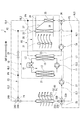
- FIG. 5 is a circuit diagram in which the vehicle air conditioner of FIG. 1 is provided with a temperature control function for a plurality of seats.
- the vehicle air conditioner 1 includes a refrigeration cycle 10 that constitutes a primary loop, and a high temperature cycle HS and a low temperature cycle CS that form a secondary loop having a flow path independent of the refrigeration cycle 10.
- the vehicle air conditioner 1 is used not only for heating and cooling the vehicle interior IN, but also for heating and cooling the seats provided in the vehicle interior IN.
- Refrigerant R circulates in the refrigeration cycle 10.
- the first heat medium HW and the second heat medium CW which are each liquid, circulate.
- the vehicle air conditioner 1 heats or cools the vehicle interior based on the refrigeration cycle 10 and the refrigerant R cooled and heated in the refrigeration cycle 10, as an example, an HVAC unit (Heating Ventilation and). It includes a temperature control mechanism 30 including an Air Conditioning Unit) and a heat radiating unit 50 that dissipates the heat of the first heat medium HW to the atmosphere.
- the refrigeration cycle 10 the temperature control mechanism 30, and the heat radiating unit 50 are connected by pipes to form a high temperature cycle HS and a low temperature cycle CS.
- the first heat medium HW flowing through the high temperature cycle HS and the second heat medium CW flowing through the low temperature cycle CS are supplied to the seat 60 provided in the vehicle interior IN.
- the refrigeration cycle 10 absorbs heat from the second heat medium CW that circulates in the low temperature cycle CS by compressing and depressurizing the circulating refrigerant R, and dissipates heat to the first heat medium HW that circulates in the high temperature cycle HS.
- the refrigeration cycle 10 includes a compressor 11, a condenser (condenser) 13, a decompression unit 15, and an evaporator (evaporator) 17.
- the condenser 13 and the evaporator 17 are connected by a refrigerant flow path L1 and a refrigerant flow path L2.
- a compressor 11 is provided in the refrigerant flow path L1, and a decompression unit 15 is provided in the refrigerant flow path L2.
- the refrigeration cycle 10 is provided at the outdoor OUT of the vehicle.
- the electric compressor 11 is applied to the compressor 11.
- the compressor 11 sucks in the low-temperature / low-pressure refrigerant R discharged from the evaporator 17, compresses it, and discharges it toward the condenser 13 as a high-temperature / high-pressure gaseous refrigerant R.
- the condenser 13 condenses the gaseous high-temperature and high-pressure refrigerant R into a high-temperature and high-pressure liquid refrigerant R.
- the condenser 13 is a heat exchanger for heating, and heats the second heat medium CW flowing through the high temperature side heat exchanger 23 constituting the high temperature cycle HS by the heat of the high temperature / high pressure refrigerant R. That is, the condenser 13 is a water-refrigerant heat exchanger that realizes heat exchange between the refrigeration cycle 10 and the high temperature cycle HS.
- the decompression unit 15 decompresses and expands the high-temperature and high-pressure liquid refrigerant R discharged from the condenser 13, and discharges the refrigerant R toward the evaporator 17.
- the evaporator 17 evaporates the refrigerant R decompressed by the decompression unit 15 to obtain a low-temperature, low-pressure gaseous refrigerant R.
- the evaporator 17 is a heat exchanger for cooling, and cools the second heat medium CW flowing through the low temperature side heat exchanger 21 constituting the low temperature cycle CS by evaporating the refrigerant R. That is, the evaporator 17 is a water-refrigerant heat exchanger that realizes heat exchange between the refrigeration cycle 10 and the low temperature cycle CS, similarly to the condenser 13.
- the temperature control mechanism 30 switches either the inside air or the outside air from the vehicle interior via an inside / outside air switching damper (not shown) to transfer the introduced air (inside air or outside air) to the downstream side.
- a blower 31 for pumping is provided.
- the temperature control mechanism 30 includes a cooler 33 which is connected to the blower 31 and is provided in the air flow path 39 inside the duct 38, a heater 35 which is provided on the downstream side of the cooler 33, and a cooler 33 and a heater. It is provided with a temperature control damper 37 provided between the 35.
- the temperature control mechanism 30 is installed in the instrument panel in front of the vehicle interior IN, for example, and blows out the air temperature-controlled by the cooler 33 and the heater 35 toward the vehicle interior, and faces the temperature control mechanism 30. It blows out to the passenger compartment IN according to either the blowout mode or the foot blowout mode, and adjusts the passenger compartment to the set temperature.
- the heat radiating unit 50 radiates the heat of the second heat medium CW flowing through the low temperature side heat exchanger 21 to the outside air.
- the heat radiating unit 50 includes a radiator 51 provided on the upstream side and a fan 53 provided on the downstream side of the radiator 51.
- the fan 53 generates an air flow by rotationally driving the motor, and the air flow passes through the radiator 51 to promote heat exchange in the radiator 51.
- heat is exchanged between the outside air and the second heat medium CW flowing inside, and heat is dissipated to the outside air.
- the vehicle air conditioner 1 includes a high temperature cycle HS whose element is a high temperature side heat exchanger 23 that exchanges heat with a condenser 13 through which a high temperature / high pressure refrigerant R flows.
- the high temperature cycle HS controls the temperature inside the vehicle interior by using the first heat medium HW heated by the high temperature side heat exchanger 23, and also controls the temperature of the seat 60 in the vehicle interior.
- the high temperature cycle HS includes the heater 35 of the temperature control mechanism 30 as an element, and further includes the following elements.
- the high temperature flow path HL1 connecting the high temperature side heat exchanger 23 and the heater 35 and the high temperature flow path connected to the heater 35 on the opposite side of the high temperature flow path HL1.
- HL2 and.
- the high temperature flow path HL1 is provided with a high temperature side pump 34 and a three-way valve 36 in this order from the side of the high temperature side heat exchanger 23.
- the high temperature side pump 34 feeds the first heat medium HW that has passed through the high temperature side heat exchanger 23 toward the heater 35.
- the three-way valve 36 controls the direction of the first heat medium HW flowing through the high temperature flow path HL1.
- the high temperature cycle HS one end is connected to the connection point P4 and the other end is connected to the three-way valve 24 which is an element of the low temperature cycle CS, and one end is connected to the three-way valve 36 and the other end is low temperature. It includes a high temperature flow path HL5 connected to the four-way valve 25, which is an element of the cycle CS.
- the three-way valve 24 includes three flow paths, a flow path 24A, a flow path 24B, and a flow path 24C, each of which is independently controlled to open and close. The same applies to the other three-way valves 32 and 36.
- the four-way valve 25 includes four flow paths, a flow path 25A, a flow path 25B, a flow path 25C, and a flow path 25D, each of which is independently controlled to open and close. The same applies to the other four-way valves 41.
- the vehicle air conditioner 1 includes a low temperature cycle CS having a low temperature side heat exchanger 21 that exchanges heat with an evaporator 17 through which a low temperature / low pressure refrigerant R flows.
- the low temperature cycle CS controls the temperature inside the vehicle interior by using the second heat medium CW cooled by the low temperature side heat exchanger 21, and also controls the temperature of the seats in the vehicle interior.
- the low temperature cycle CS includes the radiator 51 of the heat radiating unit 50 as an element, and further includes the following elements.
- the low temperature flow path CL1 connecting the radiator 51 and the low temperature side heat exchanger 21 as the flow path of the second heat medium CW, and the low temperature side heat exchanger having one end opposite to the low temperature flow path CL1. It is provided with a low temperature flow path CL2 which is connected to 21 and the other end is connected to the radiator 51.
- the low temperature flow path CL1 is provided with a four-way valve 25 and a low temperature side pump 27 in this order from the radiator 51 side. Further, the low temperature flow path CL2 is provided with a three-way valve 24.
- one end is connected to the low temperature flow path CL2 at the connection point P1 and the other end is connected to the cooler 33, and one end is connected to the cooler 33 and the other end is four-way.
- a low temperature flow path CL5 connected to the valve 25 is provided.
- the first heat medium HW and the second heat medium CW having the same components circulate respectively.
- This heat medium can be, for example, brine, that is, water containing an antifreeze solution, which does not cause a phase change in the pressure / temperature range used.
- the first heat medium HW and the second heat medium CW flow independently of each other.
- the high temperature cycle HS includes a high temperature side pump 34 and a heater 35.
- the high temperature side pump 34 circulates the first heat medium HW inside the high temperature cycle HS.
- the high temperature side pump 34 controls the water supply direction so that the refrigerant R flowing through the condenser 13 and the first heat medium HW flowing through the high temperature side heat exchanger 23 are countercurrent.
- the high temperature side pump 34 causes the first heat medium HW that has passed through the high temperature side heat exchanger 23 to flow into the heater 35.
- the first heat medium HW passes through the high temperature side heat exchanger 23, it is heated by the high temperature / high pressure refrigerant R flowing through the condenser 13. Therefore, the high temperature first heat medium HW flows into the heater 35.
- the low temperature cycle CS includes a radiator 51 and a low temperature side pump 27.
- the low temperature side pump 27 circulates the second heat medium CW in the low temperature cycle CS.
- the low temperature side pump 27 controls the water supply direction so that the refrigerant R flowing through the evaporator 17 and the second heat medium CW flowing through the low temperature side heat exchanger 21 are countercurrent.
- the low temperature side pump 27 causes the second heat medium CW that has passed through the low temperature side heat exchanger 21 to flow into the radiator 51.
- the second heat medium CW is cooled by the low-temperature / low-pressure refrigerant R flowing through the evaporator 17 when passing through the low-temperature side heat exchanger 21.
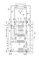
- FIG. 2 An example of controlling the temperature of the seat 60 provided in the vehicle interior by using the vehicle air conditioner 1 shown in FIG. 1 will be described with reference to FIGS. 2 to 5.
- a three-way valve 32 is provided in place of the flow control valve 29, and a four-way valve 41 is provided in place of the three-way valve 36.
- the connection point P4 and the four-way valve 41 are connected by a high temperature flow path HL6.
- the three-way valve 32 and the connection point P4 are connected by the low temperature flow path CL4. Further, as shown in FIG.
- a seat seat 60 is provided in the vehicle interior, and a hot flow path 61 and a cold flow path 63 are provided inside the seat seat 60.
- This circuit is the same in FIGS. 3 and 4.
- the hot flow path 61 is provided in the middle of the high temperature flow path HL6, and the cold flow path 63 is provided in the middle of the low temperature flow path CL4. Further, the direction in which the first heat medium HW flows in the hot flow path 61 and the direction in which the second heat medium CW flows in the cold flow path 63 are opposite to each other.
- the temperature of the seat 60 is adjusted as follows.
- the first heat medium HW heated by the high temperature side heat exchanger 23 is circulated through the high temperature flow path HL1, the high temperature flow path HL2, and the high temperature flow path HL6 to continue the first heat medium HW heated to the hot flow path 61.
- the second heat medium CW cooled by the low temperature side heat exchanger 21 is circulated through the low temperature flow path CL3, the low temperature flow path CL4, the low temperature flow path CL5, the low temperature flow path CL1 and a part of the low temperature flow path CL2.
- the cooled second heat medium CW is continuously supplied to the cold flow path 63.
- the vehicle air conditioner 1 adjusts the temperature of the seat 60 by exchanging heat between the hot flow path 61 and the cold flow path 63.
- the first heat medium HW that has passed through the heater 35 flows to the high temperature side heat exchanger 23 via the high temperature flow path HL2.
- the second heat medium CW that has passed through the low temperature side heat exchanger 21 branches into the low temperature flow path CL2 and the low temperature flow path CL3, and flows through the low temperature flow path CL2. Reaches the radiator 51, and the second heat medium CW flowing through the low temperature flow path CL3 reaches the cold flow path 63.
- the second heat medium CW that has passed through the cold flow path 63 flows into the low temperature flow path CL1 through the four-way valve 25 and reaches the low temperature side heat exchanger 21.
- the three-way valves 32 have three flow paths open, the second heat medium CW flows toward the cooler 33, and the second heat medium passes through the cooler 33.
- the CW reaches the four-way valve 25 through the low temperature flow path CL5 and flows into the low temperature side heat exchanger 21.
- the open / closed states of the flow paths of the three-way valve 24, the four-way valve 25, the three-way valve 32, and the four-way valve 41 during the dehumidifying and heating operation are as follows.
- the difference from the heating operation shown in FIG. 2 is the opening / closing of the flow path 32C of the three-way valve 32.
- a part of the first heat medium HW heated by the high temperature side heat exchanger 23 flows into the high temperature flow path HL5 through the four-way valve 41, and is further supplied to the radiator 51 through the four-way valve 25.
- the first heat medium HW that has passed through the radiator 51 flows through the high temperature flow path HL4 through the three-way valve 24 and reaches the high temperature side heat exchanger 23.
- a circulation path including the low temperature side heat exchanger 21 and the cooler 33 is formed for the cooled second heat medium CW.
- cooling operation is realized.
- a circulation pathway containing 50 radiators 51 is formed.
- the open / closed states of the flow paths of the three-way valve 24, the four-way valve 25, the three-way valve 32, and the four-way valve 41 during the cooling operation are as follows.
- the hot flow path 61 and the cold flow path 63 in the seat seat 60 are made of flexible pipe members and are provided close to each other. Proximity in the present disclosure may be in contact with or separated from each other at small intervals.
- the seat seat 60 includes a seat surface 60a, a backrest 60b rising from the seating surface 60a, and a headrest 60c attached to the upper part of the backrest 60b.
- the warm flow path 61 is provided with an introduction port 61a of the heated first heat medium HW and an discharge port 61b of the heated first heat medium HW on the seat surface 60a. ..
- the introduction port 61a is provided with a pipe 61c between the introduction port 61a and the discharge port 61b, and the first heat medium HW supplied from the introduction port 61a is discharged from the discharge port 61b through the pipe 61c.
- the pipe 61c is provided so as to meander in the order of the seat surface 60a and the backrest 60b, and is folded downward at the upper part of the backrest 60b as indicated by an arrow, and meanders in the order of the backrest 60b and the seat surface 60a, and the seat surface 60a. Is connected to the discharge port 61b.
- the cold flow path 63 is provided with an introduction port 63a for the cooled second heat medium CW and an discharge port 63b for the cooled second heat medium CW on the seat surface 60a. ..
- the introduction port 63a is provided with a pipe 63c between the introduction port 63a and the discharge port 63b, and the second heat medium CW supplied from the introduction port 63a is discharged from the discharge port 63b through the pipe 63c.
- the pipe 63c is provided so as to meander in the order of the seat surface 60a and the backrest 60b, and is folded downward at the upper part of the backrest 60b as indicated by an arrow, and meanders in the order of the backrest 60b and the seat surface 60a, and the seat surface 60a. Is connected to the discharge port 63b.
- the pipe 61c of the hot flow path 61 and the pipe 63c of the cold flow path 63 are provided adjacent to each other while meandering on the seat surface 60a and the backrest 60b. Therefore, by adjusting the amounts of the first heat medium HW and the second heat medium CW flowing through the hot flow path 61 and the cold flow path 63, the hot flow path 61 and the cold flow path 63 exchange heat with each other while exchanging heat with each other.
- the seat 60 can be cooled and heated.
- the hot flow path 61 and the cold flow path 63 are arranged close to each other on the seat seat 60.
- the seat seat 60 can be cooled and heated by adjusting the amounts of the first heat medium HW and the second heat medium CW flowing through the hot flow path 61 and the cold flow path 63, respectively.
- the first heat medium HW and the second heat medium CW supplied to the hot flow path 61 and the cold flow path 63 of the seat seat 60 are liquid. Since a liquid is used as the heat medium, the heat storage property is higher than that of air, and comfort can be maintained even when getting on and off or when the device is stopped.
- the hot flow path 61 and the cold flow path 63 are independently independent of each other. Therefore, according to the first embodiment, since the first heat medium HW and the second heat medium CW are not mixed, the volume required for mixing is not required. Further, since the roles of the first heat medium HW and the second heat medium CW can be maintained, heat management for other in-vehicle devices can be performed.
- the second embodiment proposes a vehicle air conditioner 2 capable of individually controlling the temperature of each of a plurality of, specifically four seats 60 (60A, 60B, 60C, 60D).
- the vehicle air conditioner 2 has a high temperature cycle HS in which the high temperature flow path HL6 branches into four first branch flow paths HL6A, HL6B, HL6C and HL6D.
- the high temperature flow path HL6 includes a first total amount valve 43 for adjusting the amount of the first heat medium HW flowing into the first branch flow paths HL6A, HL6B, HL6C and HL6D, and the first total amount valve 43 is a four-way valve. It is provided between 41 and the portion where the high temperature flow path HL6 branches.
- the first total amount valve 43 is provided upstream of the portion where the high temperature flow path HL6 branches, based on the direction in which the first heat medium HW flows. Upstream and downstream in the high temperature channel HL6 follow this criterion.
- the first branch flow paths HL6A, HL6B, HL6C and HL6D are provided with first individual valves 65A, 65B, 65C and 65D on the upstream side of the seat seats 60A, 60B, 60C and 60D, respectively.
- Each of the first individual valves 65A, 65B, 65C, 65D adjusts the amount of the first heat medium HW flowing into the warm flow paths 61A, 61B, 61C, 61D provided in the seat seats 60A, 60B, 60C, 60D. do. That is, the vehicle air conditioner 2 can individually adjust the amount of the first heat medium HW flowing through the hot flow paths 61A, 61B, 61C, 61D.
- the vehicle air conditioner 2 has a low temperature cycle CS in which the low temperature flow path CL4 branches into four branch flow paths CL4A, CL4B, CL4C and CL4D.
- the low temperature flow path CL4 includes a second total amount valve 45 for adjusting the amount of the second heat medium CW flowing into the second branch flow paths CL4A, CL4B, CL4C and CL4D, and the second total amount valve 45 is a four-way valve. It is provided between 41 and the portion where the low temperature flow path CL4 branches.
- the second total amount valve 45 is provided upstream of the portion where the low temperature flow path CL4 branches, based on the direction in which the second heat medium CW flows. Upstream and downstream in the low temperature channel CL4 follow this criterion.
- the second branch flow paths CL4A, CL4B, CL4C and CL4D are provided with second individual valves 67A, 67B, 67C and 67D on the upstream side of the seat seats 60A, 60B, 60C and 60D, respectively.
- Each of the second individual valves 67A, 67B, 67C, 67D adjusts the magnitude of the amount of the second heat medium CW flowing into the cold flow paths 63A, 63B, 63C, 63D provided in the seat seats 60A, 60B, 60C, 60D. do. That is, the vehicle air conditioner 2 can individually adjust the amount of the second heat medium CW flowing through the cold flow paths 63A, 63B, 63C, 63D.
- the vehicle air conditioner 2 can operate the refrigeration cycle 10 in the same manner as the vehicle air conditioner 1 to perform a heating operation (FIG. 7), a dehumidifying heating operation (FIG. 8), and a cooling operation (FIG. 9).
- a heating operation FIG. 7
- a dehumidifying heating operation FIG. 8
- a cooling operation FIG. 9
- the temperature of the seat seats 60A, 60B, 60C, and 60D is adjusted by flowing the first heat medium HW and the second heat medium CW as follows.
- the vehicle air conditioner 2 has hot channels 61A, 61B, 61C, 61D and cold channels 63A, 63B, 63C, while being heated, dehumidified, heated, or cooled by the temperature control mechanism 30.
- the amount of the second heat medium CW flowing through the 63D the temperature of the seats 60A, 60B, 60C, and 60D can be adjusted.
- the vehicle air conditioner 2 can adjust the amount of the second heat medium CW flowing in each of the hot flow paths 61A, 61B, 61C, 61D and the cold flow paths 63A, 63B, 63C, 63D.
- the vehicle air conditioner 2 according to the second embodiment exhibits the following effects 5 to 6 in addition to the effects 1 to 4 produced by the vehicle air conditioner 1.
- the amount of the second heat medium CW flowing in each of the hot flow paths 61A, 61B, 61C, 61D and the cold flow paths 63A, 63B, 63C, 63D can be adjusted. Therefore, it is possible to individually adjust the temperature of each of the plurality of seats 60A, 60B, 60C, and 60D according to the preference of the occupant.
- the vehicle air conditioner 1 according to the first aspect is cooled by a refrigeration cycle 10 in which a refrigerant circulates, a high temperature cycle HS in which a first heat medium HW heated by the refrigeration cycle 10 circulates, and a refrigeration cycle 10.
- the two heat mediums CW are provided with a low temperature cycle CS in which the CW circulates, and a seat seat 60 provided in the vehicle interior and having a hot flow path 61 and a cold flow path 63 arranged close to each other.
- the hot flow path 61 is provided in the middle of the high temperature cycle HS
- the cold flow path 63 is provided in the middle of the low temperature cycle CS.
- the hot flow path 61 and the cold flow path 63 are arranged close to each other on the seat seat 60.
- the seat seat 60 can be cooled and heated by adjusting the amounts of the first heat medium HW and the second heat medium CW flowing through the hot flow path 61 and the cold flow path 63, respectively.
- the first heat medium HW and the second heat medium CW supplied to the hot flow path 61 and the cold flow path 63 of the seat seat 60 are liquid, they can be used as heat media.
- the hot flow path 61 and the cold flow path 63 are independently independent of each other. Therefore, according to the first embodiment, since the first heat medium HW and the second heat medium CW are not mixed, the volume required for mixing is not required. Further, since the roles of the first heat medium HW and the second heat medium CW can be maintained, heat management for other in-vehicle devices can be performed.
- the vehicle air conditioner 1 according to the second aspect is provided in the vehicle interior IN and includes a temperature control mechanism 30 for adjusting the temperature of the air supplied to the vehicle interior, and the temperature control mechanism 30 provides the supplied air.
- a heater 35 for heating and a cooler 33 for cooling the supplied air are provided.
- the heater 35 is provided in parallel with the hot flow path 61 in the middle of the high temperature cycle HS, and the cooler 33 is provided in parallel with the cold flow path 63 in the middle of the low temperature cycle CS.
- the seat seat 60 can be cooled and heated while controlling the temperature of the vehicle interior IN such as heating and cooling.
- the refrigeration cycle 10 in the vehicle air conditioner 1 according to the third aspect includes a compressor 11 that compresses the refrigerant, a condenser 13 that condenses the refrigerant compressed by the compressor 11, and a refrigerant condensed by the condenser 13.
- a decompression unit 15 for depressurizing the refrigerant and an evaporator 17 for evaporating the refrigerant decompressed by the decompression unit 15 are provided.
- the high temperature cycle HS includes a high temperature side heat exchanger 23 for heat exchange between the refrigerant flowing through the condenser 13 and the first heat medium, and the low temperature cycle CS heats the refrigerant flowing through the evaporator 17 and the second heat medium.
- a low temperature side heat exchanger 21 to be replaced is provided.
- the seat seat 60 can be cooled and heated while controlling the temperature of the vehicle interior IN such as heating and cooling.
- a plurality of seat seats 60 provided in the vehicle interior, a hot flow path 61 and a cold flow path 63 provided in the respective seat seats 60, and a plurality of seats from the high temperature cycle HS.
- a first total amount valve 43 that adjusts the amount of the first heat medium HW supplied to the seat 60, and a second total amount that adjusts the amount of the second heat medium CW supplied to the plurality of seats 60 from the low temperature cycle CS.
- a valve 45 is provided.
- the air from the temperature control mechanism 30 is adjusted by adjusting the balance of the flow rates of the first heat medium HW and the second heat medium CW in the plurality of seats 60. It is possible to set the temperature to each individual's preference without depending on the blowout temperature.
- the second branch flow path CL4A, CL4B, CL4C, CL4D and the like are provided.
- the first branch flow paths HL6A, HL6B, HL6C, and HL6D are provided in each of the first branch flow paths HL6A, HL6B, HL6C, and HL6D, and are supplied to a plurality of first branch flow paths HL6A, HL6B, HL6C, and HL6D.
- a plurality of second branch flow paths CL4A, CL4B which are provided in the first individual valves 65A, 65B, 65C, 65D for adjusting the flow rate of the heat medium HW and the second branch flow paths CL4A, CL4B, CL4C, CL4D, respectively.
- the second individual valves 67A, 67B, 67C, 67D for adjusting the flow rate of the second heat medium CW supplied to the CL4C and CL4D are provided.
- the total flow rate of the heat medium required for individual temperature control is adjusted by the opening degree of the first total amount valve 43 and the second total amount valve 45.
- the opening degree of the first total amount valve 43 and the second total amount valve 45 it is possible to minimize the influence of the change in the flow rate balance when one of the occupants changes the temperature of the seat on the temperature control of the other seat.
- energy saving effect can be expected because energy is consumed only in the seat where the occupant is.
Landscapes
- Engineering & Computer Science (AREA)
- Mechanical Engineering (AREA)
- Physics & Mathematics (AREA)
- Thermal Sciences (AREA)
- Aviation & Aerospace Engineering (AREA)
- Transportation (AREA)
- Power Engineering (AREA)
- Air-Conditioning For Vehicles (AREA)
- Chair Legs, Seat Parts, And Backrests (AREA)
- Seats For Vehicles (AREA)
Abstract
Description
例えば、特許文献1は、ブライン-冷媒熱交換器において可燃性ガスの蒸発潜熱を用いて、ブラインを冷却する。特許文献1は、この低温ブラインを車室内に設置したシートを含む冷却用熱交換器に循環させて、車室内の快適性を向上させる。なお、ブラインとは、凍結温度を低くする成分が添加された水のことをいう。
また、特許文献2の提案においては、温度調節される空気の蓄熱量が不足するため、乗降時や装置の停止時には、快適性が即時に失われる。
以上より、本開示は、シートの冷却および加熱ができるのに加えて、乗降時や装置の停止時に快適性を維持しやすい車両用空調装置を提供することを目的とする。
本開示に係る車両用空調装置において、温流路は高温サイクルの途中に設けられ、冷流路は低温サイクルの途中に設けられる。
車両用空調装置1は、1次ループを構成する冷凍サイクル10と、冷凍サイクル10とは独立した流路を有する、2次ループを構成する高温サイクルHSおよび低温サイクルCSと、を備える。これにより、座席シートの冷却および加熱ができるのに加えて、乗降時や装置の停止時に快適性を維持しやすい。車両用空調装置1は車室内INの暖房および冷房に用いられるのに加えて、車室内INに設けられる座席シートの加熱および冷却に用いられる。冷凍サイクル10は、冷媒Rが循環する。高温サイクルHSおよび低温サイクルCSは、それぞれが液状の第1熱媒体HWおよび第2熱媒体CWが循環する。
車両用空調装置1は、図1に示すように、冷凍サイクル10と、冷凍サイクル10で冷却および加熱された冷媒Rに基づいて車室内の暖房または冷房をする、一例としてHVACユニット(Heating Ventilation and Air Conditioning Unit)からなる温度調節機構30と、第1熱媒体HWの熱を大気に放熱する放熱部50と、を備えている。車両用空調装置1は、冷凍サイクル10、温度調節機構30および放熱部50が配管で繋がれることで、高温サイクルHSおよび低温サイクルCSが構成される。高温サイクルHSを流れる第1熱媒体HWおよび低温サイクルCSを流れる第2熱媒体CWが、車室内INに設けられる座席シート60に供給される。
冷凍サイクル10は、循環する冷媒Rを圧縮および減圧などすることによって、低温サイクルCSを循環する第2熱媒体CWから吸熱し、高温サイクルHSを循環する第1熱媒体HWに放熱する。
冷凍サイクル10は、図1に示すように、圧縮機11、凝縮器(コンデンサ:condenser)13、減圧部15および蒸発器(エバポレータ:evaporator)17を備える。凝縮器13と蒸発器17は冷媒流路L1および冷媒流路L2で接続される。冷媒流路L1には圧縮機11が設けられ、冷媒流路L2には減圧部15が設けられる。冷凍サイクル10は、車両の車室外OUTに設けられる。
圧縮機11は、蒸発器17から放出される低温・低圧の冷媒Rを吸入して圧縮し、高温・高圧のガス状の冷媒Rとして凝縮器13に向けて吐出する。
凝縮器13は、ガス状の高温・高圧の冷媒Rを凝縮して高温・高圧の液状の冷媒Rにする。凝縮器13は、加熱用の熱交換器であって、高温・高圧の冷媒Rの熱によって高温サイクルHSを構成する高温側熱交換器23を流れる第2熱媒体CWを加熱する。つまり、凝縮器13は、冷凍サイクル10と高温サイクルHSとの間の熱交換を実現する、水-冷媒熱交換器である。
蒸発器17は、減圧部15によって減圧された冷媒Rを蒸発させて低温・低圧のガス状の冷媒Rにする。蒸発器17は、冷却用の熱交換器であって、冷媒Rの蒸発によって低温サイクルCSを構成する低温側熱交換器21を流れる第2熱媒体CWを冷却する。つまり、蒸発器17は、凝縮器13と同様に、冷凍サイクル10と低温サイクルCSとの間の熱交換を実現する、水-冷媒熱交換器である。
次に、温度調節機構30について説明する。
温度調節機構30は、図1に示すように、図示を省略する内外気切替えダンパを介して車室内からの内気または外気のいずれかを切替えて導入された空気(内気または外気)を下流側に圧送するブロア31を備えている。また、温度調節機構30は、ブロア31に連なりダクト38の内部の空気流路39に設けられる冷却器33と、冷却器33よりも下流側に設けられる加熱器35と、冷却器33と加熱器35の間に設けられる温調ダンパ37と、を備えている。
次に、放熱部50は、低温側熱交換器21を流れる第2熱媒体CWの熱を外気に放熱する。放熱部50は、上流側に設けられるラジエータ51と、ラジエータ51の下流側に設けられるファン53と、を備える。
ファン53は、モータが回転駆動されることによって、空気流れを発生させて、この空気流がラジエータ51を通過することで、ラジエータ51における熱交換を促進させる。これによってラジエータ51では、外気と内部を流れる第2熱媒体CWとが熱交換され、外気に放熱される。
車両用空調装置1は、高温・高圧の冷媒Rが流れる凝縮器13と熱交換する高温側熱交換器23を要素とする高温サイクルHSを備える。高温サイクルHSは、高温側熱交換器23で加熱された第1熱媒体HWを用いて車室内の温度調節をするとともに、車室内の座席シート60の温度調節を行う。
まず、第1熱媒体HWの流路として、高温側熱交換器23と加熱器35を接続する高温流路HL1と、高温流路HL1とは反対側で加熱器35に接続される高温流路HL2と、を備える。高温流路HL1には、高温側熱交換器23の側から高温側ポンプ34と、三方弁36と、がこの順で設けられる。高温側ポンプ34は、高温側熱交換器23を通過した第1熱媒体HWを加熱器35に向けて送給する。三方弁36は、高温流路HL1を流れる第1熱媒体HWの向きを制御する。
高温サイクルHSは、一端が接続点P4に接続され、他端が低温サイクルCSの要素である三方弁24に接続される高温流路HL4と、一端が三方弁36に接続され、他端が低温サイクルCSの要素である四方弁25に接続される高温流路HL5と、を備える。
三方弁24は、流路24A、流路24Bおよび流路24Cの三つの流路を備えており、それぞれ独立して開閉が制御される。他の三方弁32,36も同様である。
四方弁25は、流路25A、流路25B、流路25Cおよび流路25Dの四つの流路を備えており、それぞれ独立して開閉が制御される。他の四方弁41も同様である。
また、車両用空調装置1は、低温・低圧の冷媒Rが流れる蒸発器17と熱交換する低温側熱交換器21を要素とする低温サイクルCSを備える。低温サイクルCSは、低温側熱交換器21で冷却された第2熱媒体CWを用いて車室内の温度調節をするとともに、車室内の座席シートの温度調節を行う。
まず、低温サイクルCSは、第2熱媒体CWの流路としてラジエータ51と低温側熱交換器21を接続する低温流路CL1と、一端が低温流路CL1とは反対側で低温側熱交換器21と接続され、他端がラジエータ51に接続される低温流路CL2と、を備える。低温流路CL1には、ラジエータ51の側から四方弁25および低温側ポンプ27がこの順で設けられる。また、低温流路CL2には、三方弁24が設けられる。さらに、低温サイクルCSは、一端が接続点P1で低温流路CL2と接続され、他端が冷却器33に接続される低温流路CL3と、一端が冷却器33に接続され、他端が四方弁25に接続される低温流路CL5と、を備える。
本実施形態は、図1に示される車両用空調装置1を用いて、車室内に設けられる座席シート60の温度調節する例を、図2~図5を参照して説明する。
はじめに、図2を参照して、座席シート60の温度調節機能を有する車両用空調装置1の図1と異なる構成を説明する。流量調節弁29の代わりに三方弁32が設けられ、また、三方弁36の代わりに四方弁41が設けられる。また、接続点P4と四方弁41は高温流路HL6で接続される。また、三方弁32と接続点P4は低温流路CL4で接続される。
また、図2に示すように、車室内には、座席シート60が設けられ、座席シート60の内部には温流路61と冷流路63が併設されている。なお、理解を容易にするため、ここでは一つの座席だけを抽出して説明する。この回路は図3および図4においても同様である。温流路61は高温流路HL6の途中に設けられ、冷流路63は低温流路CL4の途中に設けられる。また、温流路61における第1熱媒体HWの流れる向きと冷流路63における第2熱媒体CWが流れる向きとが逆向きをなす。
図2を参照して、車両用空調装置1が暖房運転される際の冷媒R、第1熱媒体HWおよび第2熱媒体CWの流れを説明する。
車両用空調装置1における暖房運転は、高温側熱交換器23で加熱された第1熱媒体HWを高温流路HL1および高温流路HL2を循環させることで加熱器35に第1熱媒体HWを継続して供給して車室内の暖房を行う。冷却器33に第2熱媒体CWが流れていないため、ブロア31で圧送される空気は冷却器33で冷却されることなく加熱器35に至る。
なお、図2において、第1熱媒体HWおよび第2熱媒体CWが流れる流路は太く描かれている。図3以降も同様である。
高温側熱交換器23で加熱された第1熱媒体HWを高温流路HL1、高温流路HL2および高温流路HL6を循環させることで温流路61に加熱された第1熱媒体HWを継続して供給する。また、低温側熱交換器21で冷却された第2熱媒体CWを低温流路CL3、低温流路CL4、低温流路CL5および低温流路CL1と低温流路CL2の一部を循環させることで冷流路63に冷却された第2熱媒体CWを継続して供給する。車両用空調装置1は、温流路61と冷流路63で熱交換することで、座席シート60の温度調節を行う。
また、暖房運転の際に、低温側熱交換器21を通過した第2熱媒体CWは、低温流路CL2と低温流路CL3に分岐して流れ、低温流路CL2を流れる第2熱媒体CWはラジエータ51に至り、低温流路CL3を流れる第2熱媒体CWは冷流路63に至る。冷流路63を通過した第2熱媒体CWは、四方弁25を通って低温流路CL1に流れ込み、低温側熱交換器21に至る。
三方弁24 流路24A:開,流路24B:開,流路24C:閉
四方弁25 流路25A:開,流路25B:開,流路25C:開,
流路25D:閉
三方弁32 流路32A:開,流路32B:開,流路32C:閉
四方弁41 流路41A:開,流路41B:開,流路41C:開,
流路41D:閉
次に、図3を参照して、車両用空調装置1が除湿暖房運転される際の冷媒R、第1熱媒体HWおよび第2熱媒体CWの流れを説明する。なお、除湿暖房運転においては、図2を参照して説明した暖房運転と共通する部分があるため、以下では暖房運転との相違点について、除湿暖房運転を説明する。
三方弁24 流路24A:開,流路24B:開,流路24C:閉
四方弁25 流路25A:開,流路25B:開,流路25C:開,
流路25D:閉
三方弁32 流路32A:開,流路32B:開,流路32C:開
四方弁41 流路41A:開,流路41B:開,流路41C:開,
流路41D:閉
次に、図4を参照して、車両用空調装置1が冷房運転される際の冷媒R、第1熱媒体HWおよび第2熱媒体CWの流れを説明する。なお、冷房運転においても、図3を参照して説明した除湿暖房運転と共通する部分があるため、以下では除湿暖房運転との相違点について、冷房運転を説明する。
三方弁24 流路24A:開,流路24B:閉,流路24C:開
四方弁25 流路25A:開,流路25B:開,流路25C:開,
流路25D:開
三方弁32 流路32A:開,流路32B:開,流路32C:開
四方弁41 流路41A:開,流路41B:閉,流路41C:開,
流路41D:開
次に、図5を参照して、座席シート60における温流路61と冷流路63の配置例を説明する。この例における温流路61および冷流路63は可撓性の管部材から構成され、互いに近接して設けられる。本開示における近接とは、接していてもよいし、少しの間隔をあけて離れていてもよい。
座席シート60は、座面60aと、座面60aから立ち上がる背もたれ60bと、背もたれ60bの上部に取り付けられるヘッドレスト60cと、を備える。
次に、車両用空調装置1が奏する効果を説明する。
本開示の車両用空調装置1によれば、座席シート60に温流路61と冷流路63とが互いに近接して配置される。温流路61と冷流路63のそれぞれを流れる第1熱媒体HWと第2熱媒体CWの量を調整することにより、座席シート60の冷却および加熱ができる。
また、本開示の車両用空調装置1によれば、座席シート60の温流路61と冷流路63のそれぞれに供給される第1熱媒体HWと第2熱媒体CWは液状であるから、熱媒体として液体を用いているため、空気に比べて蓄熱性が高く、乗降時や装置の停止時においても快適性を維持することができる。
さらに、本開示の車両用空調装置1によれば、温流路61と冷流路63とは、それぞれが個別に独立している。
したがって、第1実施形態によれば、第1熱媒体HWと第2熱媒体CWを混合しないため、混合するために必要な容積が不要となる。
また、第1熱媒体HWと第2熱媒体CWとしての役割を維持することができるため、他の車載機器に対する熱マネジメントを行うことができる。
[複数座席シートの温度調節]
次に、図6~図9を参照して、第2実施形態を説明する。第2実施形態は、複数、具体的には四つの座席シート60(60A,60B,60C,60D)のそれぞれを個別に温度調節できる車両用空調装置2を提案する。
はじめに、図6を参照して、車両用空調装置2の回路構成を説明する。なお、車両用空調装置2は車両用空調装置1と共通する回路構成を備えているため、以下では車両用空調装置1と相違する部分を中心に車両用空調装置2を説明する。また、図6~図9において、車両用空調装置1と同じ部位、部材には図1と同じ符号を付す。
車両用空調装置2は、高温流路HL6が第1分岐流路HL6A、HL6B、HL6CおよびHL6Dの四つに分岐する高温サイクルHSを有している。高温流路HL6は、第1分岐流路HL6A、HL6B、HL6CおよびHL6Dに流入する第1熱媒体HWの量の大小を調節する第1総量弁43を備え、この第1総量弁43は四方弁41と高温流路HL6が分岐する部位との間に設けられる。第1総量弁43は、第1熱媒体HWが流れる向きを基準にすると、高温流路HL6が分岐する部位よりも上流に設けられる。高温流路HL6における上流および下流はこの基準に従う。
車両用空調装置2は、低温流路CL4が第2分岐流路CL4A、CL4B、CL4CおよびCL4Dの四つに分岐する低温サイクルCSを有している。低温流路CL4は、第2分岐流路CL4A、CL4B、CL4CおよびCL4Dに流入する第2熱媒体CWの量の大小を調節する第2総量弁45を備え、この第2総量弁45は四方弁41と低温流路CL4が分岐する部位との間に設けられる。第2総量弁45は、第2熱媒体CWが流れる向きを基準にすると、低温流路CL4が分岐する部位よりも上流に設けられる。低温流路CL4における上流および下流はこの基準に従う。
次に、図7~図9を参照して、車両用空調装置2における暖房運転、除湿暖房および冷房運転を説明する。これらの運転においても、車両用空調装置1との相違点を中心に説明する。
暖房運転において、四方弁41の流路41Aと流路41Cが開いているため、第1熱媒体HWは第1総量弁43を通って、温流路61A,61B,61C,61Dに流れる。このとき、第1総量弁43において温流路61A,61B,61C,61Dの全体に対して流れる第1熱媒体HWの量が調節される。また、温流路61A,61B,61C,61Dのそれぞれに流れる第1熱媒体HWの量が調節される。
暖房運転においては、三方弁32の流路32Aと流路32Bが開いているため、第2熱媒体CWは第2総量弁45を通って、冷流路63A,63B,63C,63Dに流れる。このとき、第2総量弁45において冷流路63A,63B,63C,63Dの全体に対して流れる第2熱媒体CWの量が調節される。また、冷流路63A,63B,63C,63Dのそれぞれに流れる第1熱媒体HWの量が調節される。
第2実施形態にかかる車両用空調装置2は、車両用空調装置1が奏する効果1~効果4に加えて、以下の効果5~効果6を奏する。
[効果5]
車両用空調装置2によれば、温流路61A,61B,61C,61Dと冷流路63A,63B,63C,63Dのそれぞれに流れる第2熱媒体CWの量を調節することができる。したがって、複数の座席シート60A,60B,60C,60Dのそれぞれにおいて乗員の好みに応じた個別の温度調整が可能である。
以上の実施形態に記載の車両用空調装置1は、以下のように把握される。
第1の態様に係る車両用空調装置1は、冷媒が循環する冷凍サイクル10と、冷凍サイクル10により加熱される第1熱媒体HWが循環する高温サイクルHSと、冷凍サイクル10により冷却される第2熱媒体CWが循環する低温サイクルCSと、車室内に設けられ、互いに近接して配置される温流路61と冷流路63とを有する座席シート60と、を備える。
車両用空調装置1において、温流路61は高温サイクルHSの途中に設けられ、冷流路63は低温サイクルCSの途中に設けられる。
第1の態様に係る車両用空調装置1によれば、座席シート60に温流路61と冷流路63とが互いに近接して配置される。温流路61と冷流路63のそれぞれを流れる第1熱媒体HWと第2熱媒体CWの量を調整することにより、座席シート60の冷却および加熱ができる。
また、車両用空調装置1によれば、座席シート60の温流路61と冷流路63のそれぞれに供給される第1熱媒体HWと第2熱媒体CWは液状であるから、熱媒体として液体を用いているため、空気に比べて蓄熱性が高く、乗降時や装置の停止時においても快適性を維持することができる。
さらに、車両用空調装置1によれば、温流路61と冷流路63とは、それぞれが個別に独立している。したがって、第1実施形態によれば、第1熱媒体HWと第2熱媒体CWを混合しないため、混合するために必要な容積が不要となる。また、第1熱媒体HWと第2熱媒体CWとしての役割を維持することができるため、他の車載機器に対する熱マネジメントを行うことができる。
第2の態様に係る車両用空調装置1は、車室内INに設けられ、車室内に供給される空気の温度を調節する温度調節機構30を備え、温度調節機構30は、供給される空気を加熱する加熱器35と、供給される空気を冷却する冷却器33と、を備える。加熱器35は、高温サイクルHSの途中に、温流路61と並列に設けられ、冷却器33は、低温サイクルCSの途中に、冷流路63と並列に設けられる。
第2の態様に係る車両用空調装置1によれば、車室内INの暖房、冷房などの温度調節を行いながら、座席シート60の冷却および加熱ができる。
第3の態様に係る車両用空調装置1における冷凍サイクル10は、冷媒を圧縮する圧縮機11と、圧縮機11で圧縮された冷媒を凝縮させる凝縮器13と、凝縮器13で凝縮された冷媒を減圧させる減圧部15と、減圧部15で減圧された冷媒を蒸発させる蒸発器17と、を備える。
高温サイクルHSは、凝縮器13を流れる冷媒と第1熱媒体とを熱交換させる高温側熱交換器23を、備え、低温サイクルCSは、蒸発器17を流れる冷媒と第2熱媒体とを熱交換させる低温側熱交換器21を、備える。
第3の態様に係る車両用空調装置1によれば、車室内INの暖房、冷房などの温度調節を行いながら、座席シート60の冷却および加熱ができる。
第4の態様に係る車両用空調装置1において、温流路61における第1熱媒体HWの流れる向きと冷流路63における第2熱媒体CWが流れる向きとが逆向きである。
第4の態様に係る車両用空調装置1によれば、対流を起こすためのファンが不要となる。
第6の態様に係る車両用空調装置1において、車室内に設けられる複数の座席シート60と、それぞれの座席シート60に設けられる温流路61および冷流路63と、高温サイクルHSから複数の座席シート60に供給される第1熱媒体HWの量を調節する第1総量弁43と、低温サイクルCSから複数の座席シート60に供給される第2熱媒体CWの量を調節する第2総量弁45と、を備える。
第5の態様に係る車両用空調装置1によれば、複数の座席シート60において第1熱媒体HWと第2熱媒体CWの流量のバランスを調節することで、温度調節機構30からの空気の吹き出し温度に依存せずに各個人の好みの温度にすることが可能となる。
第6の態様に係る車両用空調装置1によれば、複数の温流路61のそれぞれが設けられる第1分岐流路HL6A,HL6B,HL6C,HL6Dと、複数の冷流路63のそれぞれが設けられる第2分岐流路CL4A,CL4B,CL4C,CL4Dと、を備える。加えて、車両用空調装置1によれば、第1分岐流路HL6A,HL6B,HL6C,HL6Dのそれぞれに設けられ、複数の第1分岐流路HL6A,HL6B,HL6C,HL6Dに供給される第1熱媒体HWの流量を調節する第1個別弁65A,65B,65C,65Dと、第2分岐流路CL4A,CL4B,CL4C,CL4Dのそれぞれに設けられ、複数の第2分岐流路CL4A,CL4B,CL4C,CL4Dに供給される第2熱媒体CWの流量を調節する第2個別弁67A,67B,67C,67Dと、を備える。
第6の態様に係る車両用空調装置1によれば、個別の温度調節に必要な熱媒体の全流量を第1総量弁43および第2総量弁45の開度によって調節する。これにより、乗員の一人が座席の温度を変化させた時に伴う流量バランスの変化が、他の座席の温調に与える影響を最小限に抑えることができる。また、乗員がいる座席だけでエネルギーが消費されるため、省エネ効果が期待できる。
L1 冷媒流路
L2 冷媒流路
HS 高温サイクル
HL1,HL2,HL4,HL5,HL6 高温流路
HL6A,HL6B,HL6C,HL6D 第1分岐流路
CS 低温サイクル
CL1,CL2,CL3,CL4,CL5 低温流路
CL4A,CL4B,CL4C,CL4D 第2分岐流路
R 冷媒
HW 第1熱媒体
CW 第2熱媒体
10 冷凍サイクル
21 低温側熱交換器
23 高温側熱交換器
24,32,36 三方弁
25,41 四方弁
27 低温側ポンプ
30 温度調節機構
31 ブロア
43 第1総量弁
45 第2総量弁
60,60A,60B,60C,60D 座席シート
61,61A,61B,61C,61D 温流路
63,63A,63B,63C,63D 冷流路
65A,65B,65C,65D 第1個別弁
67A,67B,67C,67D 第2個別弁
Claims (6)
- 冷媒が循環する冷凍サイクルと、
前記冷凍サイクルにより加熱される液状の第1熱媒体が循環する高温サイクルと、
前記冷凍サイクルにより冷却される液状の第2熱媒体が循環する低温サイクルと、
車室内に設けられ、互いに近接して配置される温流路と冷流路とを有する座席シートと、を備え、
前記温流路は前記高温サイクルの途中に設けられ、
前記冷流路は前記低温サイクルの途中に設けられる、
車両用空調装置。
- 前記車室内に設けられ、前記車室内に供給される空気の温度を調節する温度調節機構を備え、
前記温度調節機構は、
供給される空気を加熱する加熱器と、供給される空気を冷やす冷却器と、を備え、
前記加熱器は、前記高温サイクルの途中に、前記温流路と並列に設けられ、
前記冷却器は、前記低温サイクルの途中に、前記冷流路と並列に設けられる、
請求項1に記載の車両用空調装置。
- 前記冷凍サイクルは、
前記冷媒を圧縮する圧縮機と、
前記圧縮機で圧縮された前記冷媒を凝縮させる凝縮器と、
前記凝縮器で凝縮された前記冷媒を減圧させる減圧部と、
前記減圧部で減圧された前記冷媒を蒸発させる蒸発器と、を備え、
前記高温サイクルは、前記凝縮器を流れる前記冷媒と前記第1熱媒体とを熱交換させる高温側熱交換器を、備え、
前記低温サイクルは、前記蒸発器を流れる前記冷媒と前記第2熱媒体とを熱交換させる低温側熱交換器を、備える、
請求項1または請求項2に記載の車両用空調装置。
- 前記温流路における前記第1熱媒体の流れる向きと前記冷流路における前記第2熱媒体が流れる向きとが逆向きである、
請求項1から請求項3のいずれか一項に記載の車両用空調装置。
- 前記車室内に設けられる複数の前記座席シートと、
それぞれの前記座席シートに設けられる前記温流路および前記冷流路と、
前記高温サイクルから前記複数の前記座席シートに供給される前記第1熱媒体の量を調節する第1総量弁と、
前記低温サイクルから前記複数の前記座席シートに供給される前記第2熱媒体の量を調節する第2総量弁と、を備える、
請求項1~請求項4のいずれか一項に記載の車両用空調装置。
- 複数の前記温流路のそれぞれが設けられる第1分岐流路と、
複数の前記冷流路のそれぞれが設けられる第2分岐流路と、
前記第1分岐流路のそれぞれに設けられ、複数の前記第1分岐流路に供給される前記第
1熱媒体の流量を調節する第1個別弁と、
前記第2分岐流路のそれぞれに設けられ、複数の前記第2分岐流路に供給される前記第2熱媒体の流量を調節する第2個別弁と、を備える、
請求項1~請求項5のいずれか一項に記載の車両用空調装置。
Priority Applications (3)
| Application Number | Priority Date | Filing Date | Title |
|---|---|---|---|
| US17/911,092 US12187098B2 (en) | 2020-03-13 | 2021-02-22 | Air conditioner for adjusting a temperature of a seat and an interior in a vehicle |
| CN202180020035.XA CN115243909B (zh) | 2020-03-13 | 2021-02-22 | 车辆用空调装置 |
| EP21768227.7A EP4119007B1 (en) | 2020-03-13 | 2021-02-22 | Air conditioning device for vehicle |
Applications Claiming Priority (2)
| Application Number | Priority Date | Filing Date | Title |
|---|---|---|---|
| JP2020043949A JP7388956B2 (ja) | 2020-03-13 | 2020-03-13 | 車両用空調装置 |
| JP2020-043949 | 2020-03-13 |
Publications (1)
| Publication Number | Publication Date |
|---|---|
| WO2021182094A1 true WO2021182094A1 (ja) | 2021-09-16 |
Family
ID=77670634
Family Applications (1)
| Application Number | Title | Priority Date | Filing Date |
|---|---|---|---|
| PCT/JP2021/006619 Ceased WO2021182094A1 (ja) | 2020-03-13 | 2021-02-22 | 車両用空調装置 |
Country Status (5)
| Country | Link |
|---|---|
| US (1) | US12187098B2 (ja) |
| EP (1) | EP4119007B1 (ja) |
| JP (1) | JP7388956B2 (ja) |
| CN (1) | CN115243909B (ja) |
| WO (1) | WO2021182094A1 (ja) |
Families Citing this family (1)
| Publication number | Priority date | Publication date | Assignee | Title |
|---|---|---|---|---|
| JP2025001369A (ja) * | 2023-06-20 | 2025-01-08 | サンデン株式会社 | 熱マネジメントシステム |
Citations (6)
| Publication number | Priority date | Publication date | Assignee | Title |
|---|---|---|---|---|
| JPH0258490B2 (ja) | 1985-02-22 | 1990-12-07 | Kuesters Eduard Maschf | |
| JP4677960B2 (ja) | 2006-07-26 | 2011-04-27 | 株式会社デンソー | 車両用空調装置 |
| JP2012011929A (ja) * | 2010-07-02 | 2012-01-19 | Panasonic Corp | 車両用液体循環システム |
| JP2014181574A (ja) * | 2013-03-18 | 2014-09-29 | Denso Corp | 車両用熱管理システム |
| JP2016107931A (ja) * | 2014-12-10 | 2016-06-20 | 株式会社デンソー | 車両用空調装置 |
| JP2017523073A (ja) * | 2014-06-12 | 2017-08-17 | ジェンサーム オートモーティブ システムズ チャイナリミテッド | 車両座席に座っている乗客に空気を供給するための換気装置 |
Family Cites Families (17)
| Publication number | Priority date | Publication date | Assignee | Title |
|---|---|---|---|---|
| JPH05278451A (ja) * | 1992-03-31 | 1993-10-26 | Nippondenso Co Ltd | 座席用空調装置 |
| FR2697210B1 (fr) * | 1992-10-26 | 1994-12-09 | Valeo Thermique Habitacle | Dispositif de climatisation plus particulièrement pour véhicule électrique. |
| FR2782788B1 (fr) * | 1998-08-31 | 2001-02-23 | Armines Ass Pour La Rech Et Le | Echangeur souple a effet caloduc associe a des circuits caloporteurs |
| FR2812243B1 (fr) * | 2000-07-28 | 2003-05-09 | Valeo Climatisation | Dispositif de chauffage-climatisation de l'habitacle d'un vehicule automobile |
| US20060059933A1 (en) * | 2004-09-21 | 2006-03-23 | W.E.T. Automotive Systems Ag | Heating, cooling and ventilation system for a vehicle seat |
| JP4677980B2 (ja) | 2006-01-12 | 2011-04-27 | 日産自動車株式会社 | 電圧検出装置 |
| US7950735B2 (en) * | 2008-04-07 | 2011-05-31 | GM Global Technology Operations LLC | Temperature controlled vehicle seats |
| US8136874B2 (en) * | 2009-05-29 | 2012-03-20 | GM Global Technology Operations LLC | Fluidic climate control system for a seat |
| JP6112039B2 (ja) * | 2013-04-08 | 2017-04-12 | 株式会社デンソー | 車両用熱管理システム |
| JP6197657B2 (ja) * | 2014-01-14 | 2017-09-20 | 株式会社デンソー | 車両用熱管理システム |
| WO2017065847A1 (en) * | 2015-10-14 | 2017-04-20 | Gentherm Incorporated | Systems and methods for controlling thermal conditioning of vehicle regions |
| JP6558490B2 (ja) | 2016-02-23 | 2019-08-14 | 株式会社デンソー | 車両用空調装置 |
| JP6794250B2 (ja) | 2016-12-27 | 2020-12-02 | ローム株式会社 | 位相補償回路及びこれを用いたdc/dcコンバータ |
| JP2018131006A (ja) * | 2017-02-14 | 2018-08-23 | 株式会社デンソー | 車両用空調装置 |
| CN107415636B (zh) * | 2017-08-07 | 2023-08-08 | 珠海格力电器股份有限公司 | 一种汽车、车用空调系统及车用空调控制方法 |
| KR102518177B1 (ko) | 2017-12-08 | 2023-04-07 | 현대자동차주식회사 | 차량의 공조시스템 |
| KR102751293B1 (ko) * | 2019-12-05 | 2025-01-09 | 현대자동차주식회사 | 차량용 기후제어시스템 및 그 제어방법 |
-
2020
- 2020-03-13 JP JP2020043949A patent/JP7388956B2/ja active Active
-
2021
- 2021-02-22 US US17/911,092 patent/US12187098B2/en active Active
- 2021-02-22 EP EP21768227.7A patent/EP4119007B1/en active Active
- 2021-02-22 WO PCT/JP2021/006619 patent/WO2021182094A1/ja not_active Ceased
- 2021-02-22 CN CN202180020035.XA patent/CN115243909B/zh active Active
Patent Citations (6)
| Publication number | Priority date | Publication date | Assignee | Title |
|---|---|---|---|---|
| JPH0258490B2 (ja) | 1985-02-22 | 1990-12-07 | Kuesters Eduard Maschf | |
| JP4677960B2 (ja) | 2006-07-26 | 2011-04-27 | 株式会社デンソー | 車両用空調装置 |
| JP2012011929A (ja) * | 2010-07-02 | 2012-01-19 | Panasonic Corp | 車両用液体循環システム |
| JP2014181574A (ja) * | 2013-03-18 | 2014-09-29 | Denso Corp | 車両用熱管理システム |
| JP2017523073A (ja) * | 2014-06-12 | 2017-08-17 | ジェンサーム オートモーティブ システムズ チャイナリミテッド | 車両座席に座っている乗客に空気を供給するための換気装置 |
| JP2016107931A (ja) * | 2014-12-10 | 2016-06-20 | 株式会社デンソー | 車両用空調装置 |
Non-Patent Citations (1)
| Title |
|---|
| See also references of EP4119007A4 |
Also Published As
| Publication number | Publication date |
|---|---|
| US12187098B2 (en) | 2025-01-07 |
| CN115243909B (zh) | 2025-05-02 |
| EP4119007A4 (en) | 2024-04-24 |
| EP4119007B1 (en) | 2025-04-23 |
| CN115243909A (zh) | 2022-10-25 |
| US20230158859A1 (en) | 2023-05-25 |
| JP2021142933A (ja) | 2021-09-24 |
| JP7388956B2 (ja) | 2023-11-29 |
| EP4119007A1 (en) | 2023-01-18 |
Similar Documents
| Publication | Publication Date | Title |
|---|---|---|
| JP4505510B2 (ja) | 車両用空調システム | |
| KR101745147B1 (ko) | 통합 독립공조 시스템 및 그 제어방법 | |
| JP2007278624A (ja) | ヒートポンプサイクル | |
| KR20060106507A (ko) | 차량용 시트 공조장치 | |
| US11485196B2 (en) | Air conditioning system for a motor vehicle | |
| JP2000052757A (ja) | 自動車用冷暖房装置 | |
| JP7848659B2 (ja) | 車両の熱管理システム | |
| JP6079477B2 (ja) | 車両用空調装置 | |
| JP2005289152A (ja) | 空調制御装置 | |
| JP3969099B2 (ja) | 車両用空調装置 | |
| WO2021182094A1 (ja) | 車両用空調装置 | |
| JP5117944B2 (ja) | 車両用空気調和システム | |
| CN114889396A (zh) | 热管理系统 | |
| JP2000289440A (ja) | 車両用空調装置 | |
| US20200086718A1 (en) | Vehicle hvac system with auxiliary coolant loop for heating and cooling vehicle interior | |
| US10589592B2 (en) | Air conditioning device for vehicles | |
| JP2007518624A (ja) | 空調装置 | |
| JP4859768B2 (ja) | 車両用空気調和装置 | |
| JP2000108640A (ja) | 空気調和装置 | |
| JP2010095127A (ja) | 車両用空気調和システム | |
| KR100457661B1 (ko) | 자동차용 냉난방 겸용 공조장치 | |
| JP2005247114A (ja) | 車両用空調装置 | |
| WO2023139767A1 (ja) | 車両用空調装置 | |
| WO2025057662A1 (ja) | 車両用空調装置、二次電池の加熱システム、及び二次電池の加熱方法 | |
| WO2023243367A1 (ja) | 車両用空調装置 |
Legal Events
| Date | Code | Title | Description |
|---|---|---|---|
| 121 | Ep: the epo has been informed by wipo that ep was designated in this application |
Ref document number: 21768227 Country of ref document: EP Kind code of ref document: A1 |
|
| WWE | Wipo information: entry into national phase |
Ref document number: 2021768227 Country of ref document: EP |
|
| ENP | Entry into the national phase |
Ref document number: 2021768227 Country of ref document: EP Effective date: 20221013 |
|
| NENP | Non-entry into the national phase |
Ref country code: DE |
|
| WWG | Wipo information: grant in national office |
Ref document number: 2021768227 Country of ref document: EP |
|
| WWG | Wipo information: grant in national office |
Ref document number: 202180020035.X Country of ref document: CN |