WO2021182294A1 - 測量方法、測量システム、およびプログラム - Google Patents
測量方法、測量システム、およびプログラム Download PDFInfo
- Publication number
- WO2021182294A1 WO2021182294A1 PCT/JP2021/008425 JP2021008425W WO2021182294A1 WO 2021182294 A1 WO2021182294 A1 WO 2021182294A1 JP 2021008425 W JP2021008425 W JP 2021008425W WO 2021182294 A1 WO2021182294 A1 WO 2021182294A1
- Authority
- WO
- WIPO (PCT)
- Prior art keywords
- control unit
- measurement point
- worker
- terminal
- terminal control
- Prior art date
- Legal status (The legal status is an assumption and is not a legal conclusion. Google has not performed a legal analysis and makes no representation as to the accuracy of the status listed.)
- Ceased
Links
Images


Classifications
-
- G—PHYSICS
- G01—MEASURING; TESTING
- G01C—MEASURING DISTANCES, LEVELS OR BEARINGS; SURVEYING; NAVIGATION; GYROSCOPIC INSTRUMENTS; PHOTOGRAMMETRY OR VIDEOGRAMMETRY
- G01C21/00—Navigation; Navigational instruments not provided for in groups G01C1/00 - G01C19/00
- G01C21/005—Navigation; Navigational instruments not provided for in groups G01C1/00 - G01C19/00 with correlation of navigation data from several sources, e.g. map or contour matching
-
- G—PHYSICS
- G01—MEASURING; TESTING
- G01C—MEASURING DISTANCES, LEVELS OR BEARINGS; SURVEYING; NAVIGATION; GYROSCOPIC INSTRUMENTS; PHOTOGRAMMETRY OR VIDEOGRAMMETRY
- G01C15/00—Surveying instruments or accessories not provided for in groups G01C1/00 - G01C13/00
- G01C15/002—Active optical surveying means
- G01C15/004—Reference lines, planes or sectors
-
- G—PHYSICS
- G01—MEASURING; TESTING
- G01C—MEASURING DISTANCES, LEVELS OR BEARINGS; SURVEYING; NAVIGATION; GYROSCOPIC INSTRUMENTS; PHOTOGRAMMETRY OR VIDEOGRAMMETRY
- G01C15/00—Surveying instruments or accessories not provided for in groups G01C1/00 - G01C13/00
- G01C15/02—Means for marking measuring points
-
- G—PHYSICS
- G01—MEASURING; TESTING
- G01S—RADIO DIRECTION-FINDING; RADIO NAVIGATION; DETERMINING DISTANCE OR VELOCITY BY USE OF RADIO WAVES; LOCATING OR PRESENCE-DETECTING BY USE OF THE REFLECTION OR RERADIATION OF RADIO WAVES; ANALOGOUS ARRANGEMENTS USING OTHER WAVES
- G01S17/00—Systems using the reflection or reradiation of electromagnetic waves other than radio waves, e.g. lidar systems
- G01S17/88—Lidar systems specially adapted for specific applications
- G01S17/89—Lidar systems specially adapted for specific applications for mapping or imaging
-
- G—PHYSICS
- G01—MEASURING; TESTING
- G01S—RADIO DIRECTION-FINDING; RADIO NAVIGATION; DETERMINING DISTANCE OR VELOCITY BY USE OF RADIO WAVES; LOCATING OR PRESENCE-DETECTING BY USE OF THE REFLECTION OR RERADIATION OF RADIO WAVES; ANALOGOUS ARRANGEMENTS USING OTHER WAVES
- G01S19/00—Satellite radio beacon positioning systems; Determining position, velocity or attitude using signals transmitted by such systems
- G01S19/38—Determining a navigation solution using signals transmitted by a satellite radio beacon positioning system
- G01S19/39—Determining a navigation solution using signals transmitted by a satellite radio beacon positioning system the satellite radio beacon positioning system transmitting time-stamped messages, e.g. GPS [Global Positioning System], GLONASS [Global Orbiting Navigation Satellite System] or GALILEO
- G01S19/42—Determining position
Definitions
- the present invention relates to a surveying method, a surveying system, and a program, and more specifically, to a surveying method, a surveying system, and a program for observing a line construction and a controlled cross-section for line construction.
- route survey such as center line survey and cross survey
- 3D design data based on the result of route survey.
- center points set at predetermined intervals on the center line are set.
- constituent points indicating the road width are set.
- constituent points which are change points of the terrain on the cross section orthogonal to the center line are set.
- route measurement will be carried out by installing piles and studs at the designated center points and constituent points, and based on this, work such as cutting and embankment will be carried out.
- a controlled cross-section finished shape observation will be performed to measure the designated center points and constituent points in order to confirm the finished shape.
- Patent Document 1 describes a surveying system in which three-dimensional design data is read into a mobile terminal such as a PDA (Personal / Digital / Assistant) when surveying is performed by a total station, and surveying data is collected and a surveying assistant is guided. It is disclosed.
- a mobile terminal such as a PDA (Personal / Digital / Assistant) when surveying is performed by a total station, and surveying data is collected and a surveying assistant is guided. It is disclosed.
- PDA Personal / Digital / Assistant
- Non-Patent Document 1 the three-dimensional design data in which the center line and the center point of the route are set are read into a mobile terminal capable of communicating with the surveying instrument, and the total station and the target can be combined to perform the route measurement and the management cross section. Technologies that support the execution of form observations are disclosed.
- Non-Patent Document 1 the operator selects the cross section to be measured from the mobile terminal at the start of measurement, sets the left and right offset values from the center point in the cross section, and proceeds with the observation for each point. It has become.
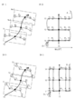
- CL is the center line
- No. 1, No. 2 ... Indicates the cross section at the center points (pile) P1 CL , P2 CL , ..., P1 1 , P1 2 , ... Indicates the constituent points
- P1 1 , P1 2 , ... Indicates the cross section No.
- the constituent points on 1 , P2 1, P2 2 , ... Are the cross-sectional Nos. 2 The above constituent points are shown.
- the worker O first receives a cross-section No. 1 from the mobile terminal. 1 is selected, as left offset value ( ⁇ from discontinued points), the point P1 1, set by entering the distance between points P CL. Then, in the surveying instrument, while tracking the target, the operator O in accordance with guidance display displayed on the display unit of the portable terminal, moves to point P1 1. Then, as shown in FIG. 1 (A-2), established the target point P1 1, thereby measuring the target to the surveying instrument from the mobile terminal. The measurement data is input to the mobile terminal. After that, as shown by the arrow A, the measurement is performed while sequentially moving P1 2 ⁇ P1 CL ⁇ ... At this time, every time the point is moved, the worker O needs to reset the cross section and the offset value from the mobile terminal, which is complicated.
- the present invention has been made in view of the above circumstances, and an object of the present invention is to provide a technique capable of efficient observation according to the topography by a simple operation in route measurement or management cross-section observation. And.
- the measuring method is configured so that the position coordinates of the worker can be acquired, and a position acquisition device including a communication unit and a terminal capable of communicating with the position acquisition device.
- This is a measurement method using a communication unit, a terminal display unit, a terminal operation unit, and a mobile terminal including a terminal control unit.
- a step of causing the acquisition device to acquire the position coordinates of the worker (e) a step of guiding the worker to the first measurement point by the terminal control unit, and (f) the terminal control unit of the terminal control unit.
- a step of setting a measurement point and (h) a step of guiding the worker to the second measurement point by the terminal control unit are provided, and then the steps (f) to (h) are repeated. Then, the operator is sequentially guided to the remaining measurement points.
- the step (c) is executed after the step (d), and in the step (c), the terminal control unit is the most from the worker who acquired the position coordinates in the step (d). It is also preferable to set a close point as the first measurement point.
- the position acquisition device transmits the target configured to be held by the operator and the distance measuring light to the target, receives the reflected light from the target, and receives the reflected light. It is a surveying instrument configured to measure a distance and an angle of a target, and the terminal control unit is based on measurement data obtained by measuring the distance and the angle of the target held by the operator. It is also preferable to acquire the position coordinates of the worker.
- the surveying instrument emits two colors of guide light so that the horizontal direction can be identified with respect to the collimation axis of the surveying instrument, and the surveying instrument can be viewed with respect to the collimation axis of the surveying instrument.
- the first first which includes a guide light irradiation unit capable of identifying a position in the quasi-axis direction, and in steps (e) and (h), the terminal control unit directs the surveying instrument to the collimation axis. It is also preferable to collimate the measurement point or the second measurement point and drive the guide light irradiation unit on the surveying instrument.
- the position acquisition device is a GNSS device that is configured to be held by the operator and can acquire a self-position value based on a navigation signal.
- the terminal control unit causes the position acquisition device to acquire the position coordinates of the worker, and the terminal control unit receives the position coordinates of the worker from the worker.
- the distance and direction to the first measurement point or the second measurement point, which is the guidance destination, are calculated, and the terminal control unit displays a compass display according to the distance and the direction on the terminal display unit. It is also preferable to do so.
- the measuring system is configured to be capable of acquiring the position coordinates of the worker, and includes a position acquisition device including a communication unit, a terminal communication unit capable of communicating with the position acquisition device, and a terminal operation unit.
- a mobile terminal including a terminal display unit and a terminal control unit, and the terminal control unit passes through a plurality of center points set at predetermined intervals on the center line of the route and orthogonal to the center line.
- the 3D design data including a plurality of measurement points set on the cross section is read, the traveling direction of observation is set in the 3D design data, and the first measurement point is set in the 3D design data.
- the position acquisition device installed at a known point acquires the position coordinates of the worker, guides the worker to the first measurement point, and causes the position acquisition device to acquire the position coordinates at the first measurement point.
- the position coordinates of the worker are acquired, the point closest to the traveling direction from the first measurement point is set as the second measurement point, and the worker is guided to the second measurement point. Has been done.
- the program according to another aspect of the present invention includes a terminal communication unit, a terminal display unit, and a terminal operation unit, which are configured to be able to acquire the position coordinates of an operator and can communicate with a position acquisition device including a communication unit.
- a computer terminal including a terminal control unit, (i) the terminal control unit crosses a plurality of center points set at predetermined intervals on the center line of a line, passes through each center point, and is orthogonal to the center line.
- a step of reading three-dimensional design data including a plurality of measurement points set on a surface, (j) a step of the terminal control unit setting an observation traveling direction in the three-dimensional design data, and (k).
- the step of acquiring the above, (o) the terminal control unit sets the point closest to the traveling direction from the first measurement point as the second measurement point, and (p) the terminal control unit The step of guiding the worker holding the target to the second measurement point, (q), and then the steps (f) to (h) are repeated to sequentially move the worker to the remaining measurement points. It is intended to execute the step of guiding.
- the operator is sequentially guided to the next measuring point and adjusted to the terrain by simply performing a simple operation of setting the starting point and the traveling direction. It is possible to carry out efficient cross-sectional surveys or controlled cross-section observations.
- (A-1) is a diagram schematically showing three-dimensional design data of a site where the height difference is small, and (A-2) is a diagram for explaining a conventional observation method.
- (B-1) is a diagram schematically showing three-dimensional design data of a site having a large height difference, and (B-2) is a diagram for explaining a preferable observation method.
- It is an overall schematic diagram of the surveying system which concerns on 1st Embodiment. It is a block diagram of the structure of the surveying system. It is a figure which shows an example of 3D design data used for the surveying method using the same surveying system. It is a flowchart of the processing of the mobile terminal in the surveying method 1 using the same surveying system.
- FIG. 2 is an overall schematic view of the surveying system (hereinafter, simply referred to as “system”) 100 according to the first embodiment of the present invention
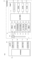
- FIG. 3 is a block diagram of the system 100.
- the system 100 includes a position acquisition device 30 and a mobile terminal 50.
- the position acquisition device 30 includes a surveying instrument 10 and a target 40.
- the surveying instrument 10 is a total station (electronic distance measuring angler).
- the surveying instrument 10 is installed at a known point via a tripod 2.
- "installing a surveying instrument at a known point” means not only “installing a surveying instrument at a known point", but also after installing the surveying instrument 10, the coordinates are known by, for example, the backward association method. Including. Further, the coordinate data of the surveying instrument 10 is input to the mobile terminal 50 and stored in the terminal storage unit 53.
- the surveying instrument 10 has a base portion 5 provided on the leveling portion 3, a suspension portion 7 that rotates horizontally around an axis HH on the base portion 5, and a shaft on the suspension portion 7. It has a telescope 9 that rotates vertically around VV.
- the bracket 7 includes a control calculation unit 23, which will be described later.
- the surveying instrument 10 has an automatic collimation function and an automatic tracking function, and the telescope 9 includes a range-finding optical system and a tracking optical system (not shown).
- the configurations of the ranging optical system and the tracking optical system are conventionally known.
- the distance measuring light and the tracking light are irradiated over the entire circumference by the cooperation of the horizontal rotation of the rack portion 7 and the vertical rotation of the telescope 9.
- the surveying instrument 10 includes a distance measuring unit 11, a tracking unit 12, a horizontal rotation drive unit 13, a vertical rotation drive unit 14, a horizontal angle detector 15, a vertical right angle detector 16, a communication unit 17, and a tilt. It includes a sensor 18, a storage unit 19, an operation unit 21, a display unit 22, and a control calculation unit 23.
- the ranging unit 11 emits ranging light using the ranging optical system, receives the reflected light from the target 40, and automatically collimates and measures the target 40.
- the tracking unit 12 emits tracking light using the tracking optical system, captures the position of the target 40 from the reflected light from the target 40, and automatically tracks the target 40 when the target 40 moves.
- the horizontal rotation drive unit 13 is a motor provided on the base unit 5.
- the horizontal rotation drive unit 13 rotates the suspension unit 7 around the axis HH with respect to the base unit 5.
- the vertical rotation drive unit 14 is a motor provided on the bracket portion 7.
- the vertical rotation drive unit 14 rotates the telescope 9 around the axis VV.
- the horizontal angle detector 15 and the vertical angle detector 16 are rotary encoders.
- the horizontal angle detector 15 detects the angle around the axis HH of the bracket 7, and the vertical angle detector 16 detects the angle around the axis VV of the telescope 9.
- the horizontal angle detector 15 and the vertical angle detector 16 form an angle measuring unit for measuring the angle of the target 40.
- the communication unit 17 is a communication control device that connects the surveying instrument 10 and the mobile terminal 50 by wire or wirelessly.
- Wi-Fi registered trademark
- 4G fourth generation mobile communication system
- short-range wireless communication standards such as Bluetooth (registered trademark) and infrared communication may be adopted.
- the tilt sensor 18 is a tilt sensor of a bubble tube type, a capacitance type, or the like, and is fixed to the upper surface of a rotation shaft (not shown) of the base portion 5.
- the storage unit 19 is a storage medium that stores, stores, and transmits information in a format that can be processed by the control calculation unit 23.
- an HDD Hard Disk, Drive
- a flash memory or the like is adopted.
- the storage unit 19 stores the measured survey data and programs for various processes.
- the operation unit 21 is a plurality of buttons provided on the outer surface of the bracket 7. Various information regarding the operation of the surveying instrument 10 can be input via the operation unit 21.
- the display unit 22 is a liquid crystal display provided on the outer surface of the bracket portion 7 and displays various information related to the survey.
- the control calculation unit 23 is a microcomputer in which a CPU (Central / Processing / Unit), a ROM (Read / Only / Memory), a RAM (Randam / Access / Memory), and the like are mounted on an integrated circuit.
- the control calculation unit 23 is connected to each unit of the surveying instrument 10.
- the control calculation unit 23 reads a program for executing various functions of the surveying instrument 10 from the storage unit 19 or RAM, controls each part of the surveying instrument 10, and performs various functions such as automatic tracking, distance measurement, and angle measurement. To execute.
- arithmetic processing is performed on the data obtained by distance measurement, angle measurement, and the like. Further, it communicates with the mobile terminal 50 via the communication unit 17, executes processing according to the instruction of the mobile terminal 50, and transmits data to the mobile terminal 50.
- the target 40 is a so-called omnidirectional prism composed of a plurality of triangular pyramid-shaped prisms radially combined, but is not limited to this.
- the target 40 reflects the incident light in the direction opposite to the incident direction.
- a length H 1 to the center O 1 comprises a known supporting member 41.
- the support member 41 is provided with a spirit level (not shown) so that it can be installed vertically.
- the target 40 was placed vertically to the measuring point via a support member 41, by ranging and angle measurement by the surveying machine 10 is installed at a known point, it is possible to obtain the three-dimensional coordinates of the center O 1. Further, by using a length H 1, it is possible to obtain the three-dimensional coordinates of the installation point P 1.
- the mobile terminal 50 is a so-called computer terminal such as a mobile phone, a smartphone, a tablet, a PDA, or a data collector.
- the mobile terminal 50 includes a terminal display unit 51, a terminal operation unit 52, a terminal storage unit 53, a terminal communication unit 54, and a terminal control unit 55.
- the terminal display unit 51 is a touch panel type liquid crystal display integrally configured with the terminal operation unit 52, but the terminal display unit 51 and the terminal operation unit 52 may be provided separately.
- the terminal display unit 51 displays screens according to the work content, and each screen can be switched according to the work content.
- the terminal storage unit 53 is, for example, an HDD.
- the terminal storage unit 53 stores a communication program, an image display program for displaying communication contents, etc. on the display unit, various programs for executing cross-sectional survey, management cross-section finished shape observation, and the like. ..
- the terminal storage unit 53 stores various information related to surveying such as the coordinates of the surveying instrument 10 and the height of the target 40. Further, the distance measurement data and the angle measurement data received from the surveying instrument 10 are stored.
- the terminal communication unit 54 is a communication control device that enables wireless communication with the surveying instrument 10 via the communication unit 17 of the surveying instrument 10, and has the same communication standard as the communication unit 17.
- the terminal control unit 55 is a control unit including at least a CPU and a memory (ROM, RAM).
- the terminal control unit 55 controls the mobile terminal 50 and the surveying instrument 10 based on the input signals from the terminal communication unit 54, the terminal operation unit 52, and the like.
- the terminal control unit 55 calls and executes a program stored in the RAM or the terminal storage unit 53 for executing the surveying method described later.
- FIG. 4 is three-dimensional design data of the work range described as an example.
- FIG. 5 is a flowchart of processing of the mobile terminal 50 when the surveying method 1 is carried out.
- FIG. 6 is an example of a screen displayed on the terminal display unit 51.
- the surveying instrument 10 is installed at a known point where the entire work range can be seen.
- the worker turns on the automatic tracking function of the surveying instrument 10 and starts the observation with the target 40 and the mobile terminal 50.
- the surveying instrument 10 continues to automatically track the target 40 held by the operator during the work.
- the terminal control unit 55 reads the three-dimensional design data.
- the three-dimensional design data may be stored in the terminal storage unit 53 in advance, or may be received from the surveying instrument 10.
- the three-dimensional design data 61 is displayed on the terminal display unit 51.
- various information such as a cross-sectional view 62, a traveling direction switching button 63 (63a, 63b) indicating the traveling direction of the selected observation, and the like are displayed on the terminal display unit 51.
- Reference numeral 64 indicates the current position mark of the target.
- step S02 the operator switches the crossing direction 63a and the route direction 63b by pressing the traveling direction switching button 63 from the terminal display unit 51 and the terminal operating unit 52, and inputs the traveling direction.
- the terminal control unit 55 sets the selected traveling direction.
- the measurement proceeds across the cross section from the start point (for example, the point P1 1 of the cross section No. 1) set in the next step S02, and the most. Move to a closer constituent point (here, point P2 1). Then, it proceeds in order from the closest point in the route direction, and when all the constituent points on the same line are measured, it moves to the point closest to the transverse direction of the same cross section, and further advances in the opposite direction in the route direction.
- the worker can judge and select the direction in which he / she can work efficiently from the topography and situation of the site.
- the crossing direction is set.
- step S03 the operator selects an arbitrary point from the terminal display unit 51 and the terminal operation unit 52 to specify a start point (for example, P1 CL , the same applies hereinafter) as the first measurement point.
- the terminal control unit 55 sets a start point accordingly, and displays the next measurement point mark 65 on the terminal display unit 51.
- step S04 the mobile terminal 50 causes the surveying instrument 10 to acquire the position coordinates of the worker.
- the 40 position coordinates of the target can be treated as the position coordinates of the operator.
- FIG. 8 is a detailed flowchart of step S04.
- the terminal control unit 55 transmits a measurement command of the target 40 to the surveying instrument 10.
- the surveying instrument 10 receives the command in step S42, the target 40 being tracked is measured (distance measuring, angle measuring) in response to the command in step S43.
- the surveying instrument 10 transmits the measurement data to the mobile terminal 50, and in step S45, the mobile terminal 50 receives the measurement data and stores it in the terminal storage unit 53.
- step S46 the terminal control unit 55 calculates and acquires the position coordinates of the target 40 from the measurement data.
- the control calculation unit 23 of the surveying instrument 10 is made to calculate the position coordinates of the target 40 from the distance measurement and angle measurement data and transmit the measurement data to the mobile terminal 50, and the mobile terminal 50 receives the measurement data. To acquire the position coordinates of the target 40.
- the terminal display unit 51 updates the current position mark 64.
- step S05 the mobile terminal 50 guides the operator to the start point (next measurement point) set in step S02.
- Guidance of the worker is performed by displaying the compass display 66 for guidance shown in FIG. 9 on the terminal display unit 51. Specifically, when the guidance is started, the mobile terminal 50 constantly repeats the operation of step S04, causes the surveying instrument 10 to measure the distance and angle of the target, and monitors the position coordinates of the target.
- the terminal control unit 55 calculates the direction of the start point from the distance D between the start point (next measurement point) and the current position of the target 40 and the target 40 for each acquired position coordinate.
- the terminal control unit 55 causes the terminal display unit 51 to display the first compass display 66.
- the first compass display 66 indicates, for example, the direction toward the starting point in a red circle indicating the compass.
- the second compass display 66 is displayed on the terminal display unit 51.
- the second compass display 66 shows, for example, an arrow indicating a direction toward the start point and a distance value for each direction in a red circle indicating the compass.
- the terminal control unit 55 displays the third compass display 66 on the terminal display unit 51.
- the third compass display 66 is, for example, a double circle of a green line, and indicates an OK state in which guidance is completed. The operator holds the target 40, moves from the current position to the next measurement point (start point), and installs the target 40 at the start point.
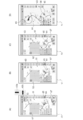
- FIG. 6D shows a compass display 66 displayed on the terminal display unit 51 together with the three-dimensional design data 61.
- the current position mark 64, the next measurement point mark 65, and the compass display 66 are displayed on the three-dimensional design data 61 indicating the site.
- the three-dimensional design data 61 and the compass display 66 are displayed according to the orientation of the mobile terminal 50, for example, based on the detection result of the electronic compass (not shown) built in the mobile terminal 50. ..
- the terminal control unit 55 When induction is completed, the terminal control unit 55, at step S06, as in step S04, the surveying instrument 10, the target 40 as the current position of the worker at the next measurement point P1 CL, was placed on the measurement points P1 1 the by ranging and angle measuring, obtains the position coordinates of the target 40 (i.e., the operator coordinates at the measurement point P CL). The acquired position coordinates are stored in the terminal storage unit 53. Then, the terminal control unit 55 changes the point display of the measurement point of the three-dimensional design data from, for example, a white circle to a colored circle (see FIGS. 6B and 6C). As a result, the operator can grasp the progress of the observation at a glance, which improves convenience.
- step S07 the terminal control unit 55 determines whether or not there is an unmeasured measurement point (next measurement point) in the work range.
- step S08 the terminal control unit 55 determines the unmeasured measurement point closest to the current position of the target 40, that is, the transverse direction from the point P1 CL to the observation traveling direction. (Point P1 2 ) is set as the next measurement point (second measurement point). Specifically, the terminal control unit 55 extracts measurement points close to the worker's current position in the direction of observation, calculates the distance between each measurement point and the worker's current position, and the distance is calculated. Set the shortest one to the next measurement point.
- step S09 similarly to step S05, the terminal control unit 55 further guided to the next measuring point (point P1 2) workers.
- step S06 when there are no unmeasured measurement points (No), the observation is terminated.
- the operator simply sets the direction of observation and the starting point, which is the first measurement point, on the mobile terminal 50, and the mobile terminal 50 guides the operator to the first measurement point. Then, the measurement of the first measurement point is performed. Then, the point closest to the observation traveling direction from the first measurement point is set as the second measurement point, and the operator is guided to the second measurement point. Therefore, the operator does not have to perform the work of setting the cross section for each measurement point, which simplifies the work.
- the worker can efficiently move to the next measurement point by simply following the guidance of the mobile terminal 50, thus reducing the work load of the worker and reducing the time. Loss can be reduced.
- the mobile terminal 50 guides the operator by displaying the compass display 66 according to the distance to the guidance destination on the terminal display unit 51 together with the three-dimensional design data 61.
- the operator can move while intuitively and clearly recognizing the distance and direction to the target measurement point, so that workability is improved.
- FIG. 10 is a flowchart of processing of the mobile terminal 50 when the surveying method 2 is carried out.
- the conditions such as the working range are the same as those used in the explanation of the surveying method 1.
- the operator sets the start point by inputting the start point, which is the first measurement point, from the terminal operation unit 52, whereas in the survey method 2, the current position of the worker is set. Is acquired, and the point closest to the current position of the worker is set as the starting point.
- the terminal control unit 55 reads the three-dimensional design data and sets the direction of observation in the same manner as in steps S01 and S02.
- step S13 as in step S04, the terminal control unit 55 causes the surveying instrument 10 to measure the target 40, and acquires the position coordinates of the target 40 as the position coordinates of the operator.
- step S14 the terminal control unit 55 sets the measurement point closest to the current position of the operator as the start point (next measurement point) which is the first measurement point. After that, in steps S16 to S19, observation is performed in the same manner as in steps S06 to S09, and the process is continued until all the measurement points are observed.
- the position acquisition device 30 is made to acquire the current position of the worker, and the measurement point closest to the current position of the worker is automatically set as the start point (first measurement point). Then, in the set observation traveling direction, the point closest to the operator at the measurement point is set as the next measurement point (second measurement point), and the operator repeats the guidance and measurement in sequence. You can proceed with the observation by an efficient route just by continuing the observation according to the guidance without paying particular attention to your own position or which cross section you are measuring.
- the process may be configured to start from step S12 while holding the three-dimensional design data.
- the operator is observing the route direction in accordance derived from the measurement point P1 1.
- the traveling direction of the observation is set in the transverse direction, and the next measurement point is set at the point P3 CL closest to the current position of the operator.
- the observation is continued in the transverse direction in the order of P3 2 ⁇ P3 1 ⁇ ....
- the same can be applied to the above-mentioned surveying method 1. In this way, if the traveling direction of the observation can be switched at any time during the observation, not only unnecessary waiting time can be avoided, but also the observation can be efficiently continued without the need for complicated settings.
- a guide point switching button 67 is provided on the display unit, and by pressing the guide point switching button 67, the current three-dimensional design data is retained and the process starts from step S13.
- It may be configured as follows. Specifically, it is assumed that the observation is being carried out as shown in FIG. 11 (A) as described above. After measuring the measurement point P3 1, the operator O is, when information is to be induced in the work impossible region, move so as to avoid unworkable areas, by pressing the induction point switch button 67 , As shown in FIG. 11 (C), the closest point P3 CL from the current position of the operator regardless of the traveling direction is set as the next measurement point, and then the point P2 CL ⁇ P1 CL ⁇ ... Continue observing.
- the guidance point (next measurement point) to be set at any time during observation, unnecessary waiting time can be avoided, and observation can be continued efficiently without the need for complicated settings. can.
- the above surveying methods 1 and 2 can be applied to line measurement by installing piles and studs at each measurement point, and can be applied to management cross-section observation after line construction by measuring each measurement point. be able to.
- FIG. 12 is a block diagram of the surveying system 200 according to the second embodiment.
- the system 200 has the same configuration as the system 100, except that the surveying instrument 210 of the position acquisition device 230 does not include the tracking unit 12.
- the operation of the mobile terminal 50 in the surveying methods 1 and 2 using the system 200 is substantially the same, except that the surveying instrument 210 does not automatically collimate the target 40. Specifically, in the process of acquiring and guiding the position coordinates of S04, S06, S13, and S16 (S05, S09, S15, S19), the operation when the surveying instrument 210 measures the distance and angle of the target 40 is different. ..
- FIG. 13 shows the operation of the system 200 when the position acquisition device 230 is made to acquire the position coordinates of the worker (target 40) at the time of acquiring and guiding the position coordinates.
- step S241 the terminal control unit 55 transmits a target measurement command to the surveying instrument 210.
- the terminal display unit 51 may be displayed to indicate that the measurement command is being transmitted, and the target operator may be notified that the measurement command is being transmitted.
- step S242 the surveying instrument 210 displays a message requesting the operator on the surveying instrument side to measure the target 40 on the display unit 22 in response to the command.
- step S243 the surveying instrument side operator operates the surveying instrument 210 according to the message, and in step S244, the surveying instrument 210 measures the distance and angle of the target.
- step S245 the surveying instrument 210 transmits the measurement data to the mobile terminal 50.
- step S246 when the mobile terminal 50 receives the measurement data, the terminal control unit 55 stores the measurement data in the terminal storage unit 53.
- step S247 the terminal control unit 55 calculates and acquires the position coordinates of the target 40 as the position coordinates of the operator from the measurement data.
- the system 200 even if the surveying instrument 210 does not have the tracking unit 12, the same effect as that of the system 100 can be obtained by the cooperation of the two workers.
- FIG. 14 is a block diagram of the surveying system 300 according to the third embodiment.
- the system 300 has substantially the same configuration as the system 100, except that the surveying instrument 310 of the position measuring device 330 further includes a guide light irradiation unit 24.
- the guide light irradiation unit 24 is arranged on the surveying instrument 310 so as to be aligned with the collimation axis of the surveying instrument 310 in the horizontal direction.
- the guide light irradiation unit 24 emits two colors of guide light (for example, red and green visible light) that are different on the left and right with respect to the collimation axis, and can identify the horizontal direction with respect to the collimation axis of the surveying instrument.
- it is configured so that the position in the collimation axis direction can be identified with respect to the collimation axis of the surveying instrument.
- the operator can be guided to a predetermined guidance point by setting the guidance point and irradiating the guide light.
- Various configurations are known as such a guide light irradiation unit 24, and for example, the configuration disclosed in Patent Document 2 can be applied.
- the light emission of the guide light irradiation unit 24 is controlled by the control of the control calculation unit 23.
- the operator holding the target 40 moves to the next measurement point set while checking the guide light.
- the guidance of the worker corresponding to steps S05, S09, S15, and S19 includes the information of the next measurement point of the guidance destination from the mobile terminal 50 to the surveying instrument 310.
- a guidance command is transmitted, the surveying instrument 310 collimates the next measurement point according to the command, drives the guide light irradiation unit 24, and controls the irradiation of the guide light.
- FIG. 15 is a schematic external view of the surveying system 400 according to the fourth embodiment
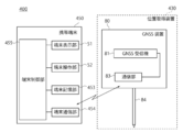
- FIG. 16 is a block diagram of the configuration of the system 400.
- the system 400 includes a position acquisition device 430 and a mobile terminal 50.
- the position acquisition device 430 is a GNSS (Global Navigation Satellite System: Global / Navigation / Satellite / System) device 80.
- GNSS Global Navigation Satellite System: Global / Navigation / Satellite / System
- the GNSS device 80 includes a GNSS receiver 81 and a communication unit 83.
- the GNSS receiver 81 is a navigation signal receiver with an integrated antenna.
- the GNSS receiver 81 can acquire its own position by receiving a navigation signal transmitted from a navigation satellite, measuring the transmission time of the navigation signal, and performing positioning.
- the GNSS receiver 81 converts the received navigation signal into an electric signal and outputs it as positioning data to the mobile terminal 50 via the communication unit 83 and the terminal communication unit 454, which will be described later.
- the GNSS receiver 81, the pole-shaped supporting member 84 the upper end having a known length H 2 is supported by the orthogonal on the surface the support member 84.
- the operator can vertically support the support member 84 and perform positioning while the GNSS receiver 81 is horizontally supported, thereby acquiring the three-dimensional coordinates of the reference point O 2 of the GNSS receiver 81. can.
- a spirit level may be provided on the support member 84, or the GNSS device 80 may be provided with a tilt sensor as disclosed in Patent Document 3.
- the communication unit 83 is a communication control device that connects the GNSS receiver 81 and the mobile terminal 540 by wire or wirelessly.
- a short-range wireless communication standard such as Bluetooth (registered trademark) or infrared communication may be adopted.
- Wi-Fi (registered trademark) or 4G (4th generation mobile communication system) which is one of the wireless LAN standards, may be adopted.
- the mobile terminal 450 is a computer terminal similar to the mobile terminal 50.
- the mobile terminal 450 includes a terminal display unit 51, a terminal operation unit 52, a terminal storage unit 453, a terminal communication unit 454, and a terminal control unit 455.
- the terminal storage unit 453 contains a communication program with the GNSS device 80, various programs for controlling the GNSS device 80, and performing road surface measurement and management cross-sectional shape observation, and controlling the display of the terminal display unit 51. Programs etc. are stored. Further, the terminal storage unit 453 stores the positioning data received from the GNSS device 80, and stores various data obtained by the arithmetic processing.
- the terminal communication unit 454 is a communication control device that enables wired or wireless communication with the GNSS device 80 via the communication unit 83 of the GNSS device 80, and has the same communication standard as the communication unit 83.
- the terminal control unit 455 is a control unit having the same configuration as the terminal control unit 55.
- the terminal control unit 455 controls the mobile terminal 50 and the GNSS device 80 based on the input signals from the terminal communication unit 454, the terminal operation unit 52, and the like.
- the terminal control unit 455 reads out various programs stored in the RAM and the terminal storage unit 453, and executes a survey method for route measurement and management cross-section observation. Further, the terminal control unit 455 acquires the three-dimensional position coordinates of the reference point O 2 of the GNSS device 80 as the position coordinates of the operator based on the positioning data received from the GNSS device 80. Further, the portable terminal 450, the operator, by entering the length H 2 of the supporting member 84, it is possible to calculate the coordinate installation point P 2 the GNSS device 80.
- the worker is the GNSS device 80. Hold and move the measurement point. Then, in step S04, S06, S13, S16 and in the worker guidance (S05, S09, S15, S19), in the acquisition of the position coordinates of the worker, the mobile terminal 450 instead of causing the surveying instrument 10 to measure the target 40.
- the GNSS device 80 is positioned, and the position coordinates of the reference point Q of the GNSS device are calculated as the position coordinates of the worker based on the positioning data.
- the position acquisition device is a GNSS device
- the same surveying methods 1 and 2 as the system 100 can be executed, and the same effect as the system 100 can be obtained.
- all or at least a part of the steps constituting the method according to the embodiment of the present invention can be realized by arbitrary hardware (processor, storage device, input / output device, etc.), software, or a combination thereof. ..
- the program or data for executing the method according to the embodiment is stored in a computer-readable storage device (storage medium).
- the storage device includes, but is not limited to, an optical disk, a magnetic disk, a magneto-optical disk, a semiconductor memory, and the like.
Landscapes
- Engineering & Computer Science (AREA)
- Radar, Positioning & Navigation (AREA)
- Remote Sensing (AREA)
- Physics & Mathematics (AREA)
- General Physics & Mathematics (AREA)
- Automation & Control Theory (AREA)
- Computer Networks & Wireless Communication (AREA)
- Electromagnetism (AREA)
- Position Fixing By Use Of Radio Waves (AREA)
Abstract
路線測設または管理断面出来形観測において、簡易な操作で、地形に合わせた効率的な観測を可能とする技術を提供する。作業者の位置座標を取得する位置取得装置(30)と、位置取得装置(30)と通信可能な携帯端末(50)を用いる測量方法であって、携帯端末(50)が、3次元設計データにおいて、観測の進行方向と第1の測定点とを設定し、位置取得装置(30)に作業者の位置座標を取得させ、携帯端末(50)が作業者を第1の測定点に誘導し、位置取得装置(30)に第1の測定点における作業者の位置座標を取得させ、第1の測定点から進行方向に最も近い点を第2の測定点に設定し、その後、作業者の位置、次の測定点の設定、次の測定点への誘導を繰り返す。
Description
本発明は、測量方法、測量システム、およびプログラムに関し、より詳細には、路線建設に係る路線測設および管理断面出来形観測のための測量方法、測量システム、およびプログラムに関する。
道路等の路線を建設する場合、まず、中心線測量、横断測量等の路線測量を行い、路線測量の結果に基づいて、3次元設計データを作成する。3次元設計データには、中心線上に所定の間隔で設定した中心点、道路幅を示す構成点、中心線に直交する断面上の地形の変化点である構成点が設定されている。現場では、指定された中心点、構成点に杭や鋲などを設置する路線測設を行い、これを基準として、切土、盛土等の作業を行う。また、路線の建設後には、出来形確認のため、指定された中心点、構成点を測定する管理断面出来形観測を行う。
近年、横断測量や管理断面出来形観測には、一般的にトータルステーション等の光波装置や、GNSS装置が用いられる。特許文献1には、トータルステーションによる測量を行う際、3次元設計データを、PDA(Personal・Digital・Assistant)等の携帯端末に読み込ませ、測量データの収集や測量補助者の誘導を行う測量システムが開示されている。
さらに、非特許文献1には、路線の中心線、中心点を設定した3次元設計データを測量機と通信可能な携帯端末に読み込ませ、トータルステーションおよびターゲットを組み合わせて、路線測設や管理断面出来形観測の実行を支援する技術が開示されている。
株式会社トプコン データコレクター FC-500 監督さん.V取扱説明書
非特許文献1の方法では、作業者は、測定の開始時に、携帯端末から測定する断面を選択し、断面における中心点からの左右のオフセット値を設定し、1点ごとに観測を進めるようになっている。図1を参照して説明する。なお、図1において、CLは中心線を、P1CL,P2CL,・・・は中心点(杭)を、No.1,No.2,…は、それぞれ中心点(杭)P1CL,P2CL,…における横断面を、P11,P12,…は、構成点を示し、P11,P12,…は、横断面No.1上の構成点を,P21,P22,…は、横断面No.2上の構成点を示す。
例えば、図1(A-1)の現場を、点P11から観測すると仮定する。作業者Oは、まず、携帯端末から断面No.1を選択し、左のオフセット値(中止点からの支距)として、点P11,点PCL間の距離を入力して設定する。次に、測量機で、ターゲットを追尾させながら、作業者Oは、携帯端末の表示部に表示される誘導表示に従って、点P11に移動する。そして、図1(A-2)に示すように、ターゲットを点P11に設置し、携帯端末から測量機にターゲットを測定させる。測定データは携帯端末に入力される。その後、矢印Aで示すように、P12→P1CL→・・・を順次移動しながら測定する。この時、点を移動するごとに、作業者Oが、携帯端末から断面とオフセット値を設定し直す必要があり作業が煩雑であった。
また、図1(B-1)のように、断面に高低差がある地形の場合、断面毎に測定すると、作業者Oは上下の移動を繰り返す必要があり効率が悪い。そこで、図1(B-2)に矢印Bで示すように、同じ高さの測定点をP11→P21→P31→・・・の順序で観測作業を進めることが好ましい。しかし、この場合も、断面を移動する毎に、携帯端末で断面とオフセット値を設定し直す必要があり、作業が煩雑であった。
本発明は、係る事情を鑑みてなされたものであり、路線測設または管理断面出来形観測において、簡易な操作で、地形に合わせた効率的な観測を可能とする技術を提供することを目的とする。
上記目的を達成するために、本発明の1つの態様に係る測量方法は、作業者の位置座標を取得可能に構成され、通信部を備える位置取得装置と、前記位置取得装置と通信可能な端末通信部、端末表示部、端末操作部および端末制御部を備える携帯端末とを用いる測量方法であって、(a)前記端末制御部が、路線の中心線上に所定の間隔で設定された複数の中心点と、各中心点を通り前記中心線に直交する横断面上に設定された複数の測定点とを備える3次元設計データを読み込むステップと、(b)前記端末制御部が、前記3次元設計データにおいて観測の進行方向を設定するステップと、(c)前記端末制御部が、前記3次元設計データにおいて第1の測定点を設定するステップと、(d)前記端末制御部が、前記位置取得装置に前記作業者の位置座標を取得させるステップと、(e)前記端末制御部が、前記作業者を前記第1の測定点まで誘導するステップと、(f)前記端末制御部が、前記位置取得装置に前記第1の測定点における前記作業者の位置座標を取得させるステップと、(g)前記端末制御部が、前記第1の測定点から前記進行方向に最も近い点を第2の測定点に設定するステップと、(h)前記端末制御部が、前記作業者を前記第2の測定点まで誘導するステップとを備え、その後、前記ステップ(f)~前記ステップ(h)を繰り返して、順次作業者を残りの測定点に誘導する。
上記態様において、前記ステップ(c)は、前記ステップ(d)の後に実行され、前記ステップ(c)において、前記端末制御部は、前記ステップ(d)で位置座標を取得した前記作業者から最も近い点を、前記第1の測定点として設定することも好ましい。
また、上記態様において、前記位置取得装置は、前記作業者に保持されるように構成されたターゲットと、測距光を前記ターゲットに送光し、前記ターゲットからの反射光を受光して、前記ターゲットを測距および測角するように構成された測量機であり、前記端末制御部は、前記作業者に保持された前記ターゲットを測距および測角することにより得られる測定データに基づいて、前記作業者の位置座標を取得することも好ましい。
また、上記態様において、前記測量機は、2色のガイド光を発光し、前記測量機の視準軸に対して水平方向を識別可能とするとともに、前記測量機の視準軸に対して視準軸方向の位置を識別可能とするガイド光照射部を備え、ステップ(e)およびステップ(h)において、前記端末制御部が、前記測量機に視準軸が誘導先である前記第1の測定点または前記第2の測定点を視準させ、前記測量機に前記ガイド光照射部を駆動させることにより行うことも好ましい。
また、上記態様において、前記位置取得装置は、前記作業者に保持されるように構成され、航法信号に基づいて、自位値を取得可能なGNSS装置であることも好ましい。
また、上記態様において、前記ステップ(e)および前記ステップ(h)において、前記端末制御部が、前記位置取得装置に前記作業者の位置座標を取得させ、前記端末制御部が、前記作業者から誘導先である前記第1の測定点または前記第2の測定点までの距離および方向を計算し、前記端末制御部が、前記端末表示部に、前記距離および前記方向に応じたコンパス表示を表示することも好ましい。
また、本発明の別の態様に係る測量システムは、作業者の位置座標を取得可能に構成され、通信部を備える位置取得装置と、前記位置取得装置と通信可能な端末通信部、端末操作部、端末表示部および端末制御部を備える携帯端末とを備え、前記端末制御部が、路線の中心線上に所定の間隔で設定された複数の中心点と、各中心点を通り前記中心線に直交する横断面上に設定された複数の測定点とを備える3次元設計データを読み込み、前記3次元設計データにおいて観測の進行方向を設定し、前記3次元設計データにおいて第1の測定点を設定し、既知点に設置された前記位置取得装置に、前記作業者の位置座標を取得させ、前記作業者を前記第1の測定点まで誘導し,前記位置取得装置に、前記第1の測定点における前記作業者の位置座標を取得させ、前記第1の測定点から前記進行方向に最も近い点を第2の測定点に設定し、前記作業者を前記第2の測定点まで誘導するように構成されている。
また、本発明の別の態様に係るプログラムは、作業者の位置座標を取得可能に構成され、通信部を備える位置取得装置と通信可能な端末通信部と、端末表示部と、端末操作部と、端末制御部とを備えるコンピュータ端末に、(i)前記端末制御部が、路線の中心線上に所定の間隔で設定された複数の中心点と、各中心点を通り前記中心線に直交する横断面上に設定された複数の測定点とを備える3次元設計データを読み込むステップと、(j)前記端末制御部が、前記3次元設計データにおいて観測の進行方向を設定するステップと、(k)前記端末制御部が、前記3次元設計データにおいて第1の測定点を設定するステップと、(l)前記端末制御部が、前記位置取得装置に、作業者の位置座標を取得するステップと、(m)前記端末制御部が、前記作業者を前記第1の測定点まで誘導するステップと、(n)前記端末制御部が、前記位置取得装置に前記第1の測定点における作業者の位置座標を取得するステップと、(o)前記端末制御部が、前記第1の測定点から前記進行方向に最も近い点を第2の測定点に設定するステップと、(p)前記端末制御部が、前記ターゲットを保持する作業者を前記第2の測定点まで誘導するステップと、(q)その後、前記ステップ(f)~前記ステップ(h)を繰り返して、順次作業者を残りの測定点へと誘導するステップを実行させるものである。
上記態様に係る測量方法、測量システム、およびプログラムによれば、開始点と、進行方向の設定という簡単な操作を行うだけで、作業者を順次、次の測定点へと誘導し、地形に合わせた効率的な横断測量または管理断面出来形観測を実行することができる。
以下、本発明の好適な実施の形態について、図面を参照して説明するが、本発明はこれに限定されるものではない。また、各実施の形態において、同一の機能および構成を有する部材には、同一の符号を付し、対応する機能を有する部材には、同一の名称を付し、重複する説明は適宜省略する。
(第1の実施形態)
(システムの全体構成)
図2は、本発明の第1の実施の形態に係る測量システム(以下、単に「システム」という。)100の全体概略図であり、図3は、システム100の構成ブロック図である。システム100は、位置取得装置30と、携帯端末50とを備える。
(システムの全体構成)
図2は、本発明の第1の実施の形態に係る測量システム(以下、単に「システム」という。)100の全体概略図であり、図3は、システム100の構成ブロック図である。システム100は、位置取得装置30と、携帯端末50とを備える。
(位置取得装置30の構成)
位置取得装置30は、測量機10とターゲット40とで構成されている。
測量機10は、トータルステーション(電子式測距測角儀)である。測量機10は、三脚2を介して、既知点に設置される。なお、本明細書において、「測量機を既知点に設置する」とは、「座標既知の点に設置すること」のみならず、測量機10を設置した後、例えば後方交会法等により座標既知とすることも含む。また、測量機10の座標データは、携帯端末50に入力され、端末記憶部53に格納される。
位置取得装置30は、測量機10とターゲット40とで構成されている。
測量機10は、トータルステーション(電子式測距測角儀)である。測量機10は、三脚2を介して、既知点に設置される。なお、本明細書において、「測量機を既知点に設置する」とは、「座標既知の点に設置すること」のみならず、測量機10を設置した後、例えば後方交会法等により座標既知とすることも含む。また、測量機10の座標データは、携帯端末50に入力され、端末記憶部53に格納される。
測量機10は、外観上、整準部3の上に設けられた基盤部5と、基盤部5の上で軸H-H周りに水平回転する托架部7と、托架部7に軸V-V周りに鉛直回転する望遠鏡9と、を有する。托架部7には、後述する制御演算部23が収容されている。
測量機10は、自動視準機能および自動追尾機能を備え、望遠鏡9に、図示しない測距光学系および追尾光学系が収容されている。測距光学系および追尾光学系の構成は、従来公知である。測量機10では、托架部7の水平回転と、望遠鏡9の鉛直回転の協働により測距光および追尾光が全周にわたって照射される。
図3に示すように、測量機10は、測距部11、追尾部12、水平回転駆動部13、鉛直回転駆動部14、水平角検出器15、鉛直角検出器16、通信部17、チルトセンサ18、記憶部19、操作部21、表示部22、および制御演算部23を備える。
測距部11は、上記測距光学系を用いて測距光を出射し、ターゲット40からの反射光を受光して、自動視準およびターゲット40を測距する。
追尾部12は、上記追尾光学系を用いて追尾光を出射し、ターゲット40からの反射光からターゲット40の位置を捕捉して、ターゲット40が移動した場合にターゲット40を自動追尾する。
水平回転駆動部13は、基盤部5に設けられたモータである。水平回転駆動部13は、基盤部5に対して托架部7を軸H-H周りに回転する。鉛直回転駆動部14は、托架部7に設けられたモータである、鉛直回転駆動部14は、望遠鏡9を軸V-V周りに回転する。
水平角検出器15、鉛直角検出器16は、ロータリエンコーダである。水平角検出器15は、托架部7の軸H-H周りの角度を検出し、鉛直角検出器16は、望遠鏡9の軸V-V周りの角度を検出する。この結果、水平角検出器15と鉛直角検出器16が、ターゲット40を測角する測角部を構成する。
通信部17は、測量機10と携帯端末50を有線または無線で接続する通信制御装置である。通信部17を実現する通信規格として、無線LAN規格の一つであるWi-Fi(登録商標)や4G(第4世代移動通信システム)を採用してもよい。あるいはBluetooth(登録商標)、赤外線通信等の近距離無線通信規格を採用してもよい。
チルトセンサ18は、気泡管式、静電容量式等の傾斜センサであり、基盤部5の回転軸(図示せず)の上面に固定されている。水平回転駆動部13の回転軸が1回ずつ正反回転したときのチルトセンサ18の値が読み取られ、正反回転でのずれ量に基づき、整準部3の水平が調整される。
記憶部19は、情報を制御演算部23が処理可能な形式で記憶、保存及び伝達する記憶媒体であり、例えば、HDD(Hard・Disc・Drive)、フラッシュメモリ等が採用される。記憶部19には、測定した測量データと、各種処理のためのプログラムが格納される。
操作部21は、托架部7の外面に設けられた複数のボタンである。操作部21を介して、測量機10の動作に関する各種情報が入力可能である。
表示部22は、托架部7の外面に設けられた液晶ディスプレイであり、測量に関する各種情報を表示する。
制御演算部23は、CPU(Central・Processing・Unit)、ROM(Read・Only・Memory),RAM(Randam・Access・Memory)等を集積回路に実装したマイクロコンピュータである。制御演算部23は、測量機10の各部と接続されている。制御演算部23は、測量機10の各種機能を実行するためのプログラムを、記憶部19またはRAMから読み出して、測量機10の各部を制御して、自動追尾、測距、測角等各種機能を実行する。また、測距、測角等により得られたデータに演算処理を行う。また、通信部17を介して、携帯端末50と通信し、携帯端末50の命令に従って処理を実行し、携帯端末50にデータを送信する。
ターゲット40は、複数の三角錐状のプリズムを放射状に組み合わせて構成された、いわゆる全方位プリズムであるが、これに限定されない。ターゲット40は、入射光を、入射方向と反対の方向に反射する。
ターゲット40は、中心O1までの長さH1が既知の支持部材41を備える。支持部材41は、図示しない水準器を備え、鉛直に設置できるようになっている。支持部材41を介して測定点に鉛直に設置したターゲット40を、既知点に設置した測量機10で測距・測角することにより、中心O1の3次元座標を求めることができる。また、長さH1を用いて、設置点P1の3次元座標を求めることができる。
(携帯端末50の構成)
携帯端末50は、携帯電話、スマートフォン、タブレット、PDA、データコレクタ等の、いわゆるコンピュータ端末である。
携帯端末50は、携帯電話、スマートフォン、タブレット、PDA、データコレクタ等の、いわゆるコンピュータ端末である。
携帯端末50は、端末表示部51、端末操作部52、端末記憶部53、端末通信部54および端末制御部55を備える。
端末表示部51は、端末操作部52と一体に構成されたタッチパネル式の液晶ディスプレイであるが、端末表示部51と端末操作部52が、別個に設けられていてもよい。端末表示部51は、作業内容に応じた画面を表示し、各画面は作業内容に応じて切り替えられるようになっている。
端末記憶部53は、例えばHDDである。端末記憶部53には、通信プログラム、表示部に作業内容等、通信内容等を表示するための画像表示プログラム、横断測量、管理断面出来形観測を実行するための各種プログラム等が記憶されている。
また、端末記憶部53には、測量機10の座標、ターゲット40の高さ等の測量に関する各種情報が記憶される。また、測量機10から受信した、測距データ、測角データが記憶される。
端末通信部54は、測量機10の通信部17を介して、測量機10と無線通信可能とする通信制御装置であり、通信部17と同じ通信規格を有する。
端末制御部55は、少なくともCPU及びメモリ(ROM,RAM)等を備える制御ユニットである。端末制御部55は、端末通信部54、端末操作部52等からの入力信号に基づいて、携帯端末50および測量機10を制御する。端末制御部55は、RAMや、端末記憶部53に記憶された、後述する測量方法を実行するためのプログラムを呼び出して実行する。
(測量方法1)
次に、システム100を用いた測量方法1について説明する。図4は、例として説明する作業範囲の3次元設計データである。図5は、測量方法1を実施する際の携帯端末50の処理のフローチャートである。図6は、端末表示部51に表示される画面の例である。
次に、システム100を用いた測量方法1について説明する。図4は、例として説明する作業範囲の3次元設計データである。図5は、測量方法1を実施する際の携帯端末50の処理のフローチャートである。図6は、端末表示部51に表示される画面の例である。
まず、図4に示すような、路線の中心線CL上に所定の間隔で設定された複数の中心点P1CL,P2CL,…と、各中心点を通り前記中心線に直交する横断面No.1,No.2,…上に設定された複数の測定点P11,P12,…,P21,P22,…とを備える3次元設計データを用意する。
次に、現場において、測量機10を、作業範囲全体を見通せる既知点に設置する。
そして、作業者は、測量機10の自動追尾機能をONにして、ターゲット40と、携帯端末50を持って観測を開始する。これにより、測量機10は、作業中、作業者が保持するターゲット40を自動追尾し続ける。
観測を開始すると、まず、ステップS01で、端末制御部55は、3次元設計データを読み込む。3次元設計データは、予め端末記憶部53に保存しておいてもよく、測量機10から受信してもよい。3次元設計データ61は、図6(A)に示すように、端末表示部51に表示される。また、端末表示部51には、断面図62,選択されている観測の進行方向示す進行方向切替ボタン63(63a,63b)等種々の情報が表示される。また、符号64は、ターゲットの現在位置マークを示す。
次に、ステップS02で、作業者が、端末表示部51および端末操作部52から、進行方向切替ボタン63を押すことで、横断方向63aと路線方向63bを切り替えて、進行方向を入力する。これにより、端末制御部55は選択された進行方向を設定する。
横断方向を選択すると、図7(A)に示すように、次のステップS02で設定する第1の測定点である開始点(例えば断面No.1の点P1CL)から、横断方向に向かって最も近い点から順に進行し、断面上の点を全て測定すると、最も近い断面(No.2)に移動し、これを繰り返す。
一方、路線方向を選択すると、図7(B)に示すように、次のステップS02で設定する開始点(例えば断面No.1の点P11)から、断面をまたいで測定が進行し、最も近い構成点(ここでは、点P21)に移動する。そして、路線方向に向かって最も近い点から順に進行し、同一線上の構成点を全て測定すると、同一断面の横断方向に最も近い点に移動し、さらに路線方向に逆方向に進行する。
作業者は、現場の地形や状況から、効率よく作業することができる方向を判断し、選択することができる。ここでは横断方向を設定したと仮定する。
次に、ステップS03で、作業者が端末表示部51および端末操作部52から、任意の点を選択することにより第1の測定点として開始点(例えばP1CL,以下同じ)を指定する。端末制御部55はこれに応じて、開始点を設定し、端末表示部51に次の測定点マーク65を表示する。
次に、ステップS04で、携帯端末50は、測量機10に作業者の位置座標を取得させる。ターゲットの40の位置座標は、作業者の位置座標として扱うことができる。
図8は、ステップS04の詳細なフローチャートである。位置座標の取得を開始すると、ステップS41で、端末制御部55は、測量機10にターゲット40の測定命令を送信する。ステップS42で、測量機10が命令を受信すると、ステップS43で、命令に応じて追尾中のターゲット40を測定(測距、測角)する。次に、ステップS44で、測量機10は、測定データを携帯端末50に送信し、ステップS45で、携帯端末50は、測定データを受信して、端末記憶部53に記憶する。
次に、ステップS46で、端末制御部55が、測定データから、ターゲット40の位置座標を算出して取得する。あるいは、測量機10の制御演算部23に、測距、測角データからターゲット40の位置座標を算出させて、測定データとして、携帯端末50に送信させ、携帯端末50が、測定データを受信してターゲット40の位置座標を取得する。
なお、システム100において、携帯端末50がターゲット40の位置座標を取得すると、端末表示部51は、現在位置マーク64を更新する。
次に、ステップS05で、携帯端末50は、ステップS02で設定した開始点(次の測定点)まで、作業者を誘導する。
作業者の誘導は、端末表示部51に、図9に示す、誘導のためのコンパス表示66を表示することにより行う。具体的には、誘導を開始すると、携帯端末50は、ステップS04の動作を常時繰り返して、測量機10にターゲットを測距・測角させてターゲットの位置座標をモニターする。
次に、端末制御部55は、取得した位置座標毎に、開始点(次の測定点)とターゲット40の現在位置との距離Dおよびターゲット40から開始点の方向を算出する。距離Dが所定の上限値(例えば、3m)以上の場合、端末制御部55は、端末表示部51に、第1のコンパス表示66を表示させる。第1のコンパス表示66は、例えば、コンパスを示す赤い丸の中に、開始点に向かう方向を示す。これにより、作業者は、ターゲット40を保持しながら、第1のコンパス表示66に従って移動するだけで、設定した開始点に近づくことができる。
そして、距離Dが所定の下限値(例えば0.5m)以上かつ所定の上限値(例えば、3m)未満である場合、端末表示部51に、第2のコンパス表示66を表示する。第2のコンパス表示66は、例えばコンパスを示す赤い丸の中に、開始点に向かう方向を示す矢印と、その方向ごとの距離値を示す。これにより、作業者は、距離の意識を明確にした状態で、行きすぎたりすることなく、的確に開始点に近づくことができる。
そして、距離Dが所定の下限値(例えば0.5m)未満となったときに、端末制御部55は、端末表示部51に、第3のコンパス表示66を表示する。第3のコンパス表示66は、例えば緑色線の二重丸であり、誘導が完了したOK状態を示す。作業者は、ターゲット40を保持して現在位置から次の測定点(開始点)に移動し、開始点にターゲット40を設置する。
図6(D)は、端末表示部51に、3次元設計データ61と共に表示されたコンパス表示66を示す。このように現場を示す3次元設計データ61に重ねて、現在位置マーク64、次の測定点マーク65およびコンパス表示66が表示される。これにより、作業者は、現在位置、誘導先および移動すべき方向を直観的に理解して円滑に次の測定点まで移動することができる。3次元設計データ61およびコンパス表示66は、例えば、携帯端末50に内蔵される電子コンパス(図示せず)の検出結果に基づいて、携帯端末50の向きに応じて表示されるようになっている。
誘導が完了すると、端末制御部55は、ステップS06で、ステップS04と同様にして、測量機10に、次の測定点P1CLにおける作業者の現在位置として、測定点P11に設置したターゲット40を測距および測角させて、ターゲット40の位置座標(すなわち、測定点PCLにおける作業者の位置座標)を取得する。取得した位置座標は、端末記憶部53に記憶される。
そして、端末制御部55は、3次元設計データの測定点のポイント表示を、例えば、白抜き丸から色付きの丸というように変更する(図6(B),(C)参照)。これにより、作業者は、観測の進捗状況を一見して把握することができるので利便性が向上する。
そして、端末制御部55は、3次元設計データの測定点のポイント表示を、例えば、白抜き丸から色付きの丸というように変更する(図6(B),(C)参照)。これにより、作業者は、観測の進捗状況を一見して把握することができるので利便性が向上する。
次に、ステップS07で、端末制御部55は、作業範囲において未測定の測定点(次の測定点)があるか否かを判断する。
未測定の測定点がある場合(Yes)、ステップS08で、端末制御部55は、ターゲット40の現在位置、すなわち点P1CLから観測の進行方向である横断方向に、最も近い未測定の測定点(点P12)を、次の測定点(第2の測定点)として設定する。具体的には、端末制御部55が、観測の進行方向に作業者の現在位置に近接する測定点を抽出し、それぞれの測定点と作業者の現在位置との距離を算出し、その距離が最も短いものを次の測定点に設定する。
次に、ステップS09で、ステップS05と同様に、端末制御部55は、作業者をさらに次の測定点(点P12)まで誘導する。
そして、ステップS06に戻り、ステップS07で未測定の測定点がなくなるまで、ステップS06~S09を繰り返す。一方、ステップS06で、未測定の測定点がなくなった場合(No)、観測を終了する。
本測量方法では、作業者が、携帯端末50で、観測の進行方向と、第1の測定点である開始点を設定するだけで、携帯端末50は、作業者を第1の測定点まで誘導し、第1の測定点の測定を行う。そして、第1の測定点から、観測の進行方向に最も近い点を、第2の測定点として設定し、第2の測定点まで作業者を誘導する。したがって、作業者は、測定点ごとに、横断面を設定するという作業を行わなくてもよいので作業が簡便になる。
また、各測定点間において、作業者は、単に携帯端末50の誘導に従って、移動していけば、効率よく次の測定点に移動することができるので、作業者の作業負担を低減し、時間的なロスを低減することができる。
また、携帯端末50は、端末表示部51に、誘導先までの距離に応じたコンパス表示66を3次元設計データ61と合わせて表示して作業者を誘導する。これにより作業者は、目的の測定点までの距離および方向を、直観的かつ明確に認識しながら移動することができるので、作業性が向上する。
(測量方法2)
次に、システム100を用いる測量方法2について説明する。図10は、測量方法2を実施する際の携帯端末50の処理のフローチャートである。作業範囲等の条件は測量方法1の説明で用いたものと同じである。
次に、システム100を用いる測量方法2について説明する。図10は、測量方法2を実施する際の携帯端末50の処理のフローチャートである。作業範囲等の条件は測量方法1の説明で用いたものと同じである。
しかし、測量方法1では、作業者が端末操作部52から第1の測定点である開始点を入力することにより開始点の設定を行うのに対して、測量方法2では、作業者の現在位置を取得し、作業者の現在位置から、最も近い点を開始点として設定する。
具体的には、ステップS11,S12で、ステップS01,S02と同様に、端末制御部55が、3次元設計データを読み込み、観測の進行方向を設定する。
次に、ステップS13で、ステップS04と同様に、端末制御部55が、測量機10にターゲット40の測定を行わせ、ターゲット40の位置座標を作業者の位置座標として取得する。
次に、ステップS14で、端末制御部55が、作業者の現在位置から最も近い測定点を、第1の測定点である開始点(次の測定点)として設定する。その後、ステップS16~S19で、ステップS06~S09と同様にして観測を行い、全ての測定点を観測するまで、処理を続行する。
このように、測量方法2では、位置取得装置30に作業者の現在位置を取得させ、作業者の現在位置から最も近い測定点を開始点(第1の測定点)として自動的に設定する。そして、設定された観測の進行方向に、測定点における作業者から最も近い点を、次の測定点(第2の測定点)として設定し、順次誘導、測定を繰り返すことで、作業者は、自身の位置や、どの断面を測定中かなどを特に意識せず、誘導に従って観測を続行するだけで、効率的なルートで観測を進めることができる。
本方法において、例えば、作業途中に、進行方向切替ボタン63(63a,63b)を押すことで、3次元設計データを保持しながら、ステップS12から開始するように構成されていてもよい。
具体的には、図11(A)に示すように、作業者が、測定点P11から誘導に従って路線方向に観測中であると仮定する。測定点P31を測定後、作業者Oが、重機が一時的に作業中等で作業不可能な領域に誘導されそうになった場合に、その場で、進行方向切替ボタン63を押すことで、図11(B)に示すように、観測の進行方向を横断方向に設定し、作業者の現在位置から最も近い点P3CLを次の測定点を設定する。その後、P32→P31→…と、横断方向に観測を続行する。上記測量方法1においても同様にすることができる。このように、観測中に観測の進行方向を随時切替可能に構成すると、無駄な待ち時間が回避できるだけでなく、煩雑な設定を行う必要なく、効率よく観測を続行することができる。
また、本方法において、図6に示すように、表示部に誘導点切替ボタン67を設け、誘導点切替ボタン67を押すことで、現在の3次元設計データを保持しながら、ステップS13から開始するように構成されていてもよい。具体的には、上記同様図11(A)に示すように観測中であると仮定する。測定点P31を測定後、作業者Oが、作業不可能な領域に誘導されそうになった場合に、作業不可能な領域を避けるように移動して、誘導点切替ボタン67を押すことで、図11(C)に示すように、作業者の現在位置から進行方向に関わらず最も近い点P3CLを次の測定点に設定し、その後、点P2CL→P1CL→…と、路線方向に観測を続行する。
このように、観測中に誘導点(次の測定点)を、随時設定可能に構成することにより、無駄な待ち時間が回避でき、煩雑な設定を行う必要なく、効率よく観測を続行することができる。このことは、設定された観測方向に最も近い未測定な測定点が複数ある場合や、携帯端末50が設定する次の測定点(誘導点)以外の点を次の測定点としたい場合に、特に有利である。
なお、上記測量方法1、2は、各測定点に杭や鋲を設置することで路線測設に適用でき、各測定点を測定を行うことで路線建設後の管理断面出来形観測に適用することができる。
(第2の実施の形態)
図12は、第2の実施の形態に係る測量システム200の構成ブロック図である。システム200は概略システム100と同様の構成を有するが、位置取得装置230の測量機210が、追尾部12を備えない点で異なる。
図12は、第2の実施の形態に係る測量システム200の構成ブロック図である。システム200は概略システム100と同様の構成を有するが、位置取得装置230の測量機210が、追尾部12を備えない点で異なる。
システム200を用いる場合、ターゲット40を保持して、測定点を移動するターゲット側作業者と、測量機を操作する測量機側作業者の2名で観測を行う。
システム200を用いる測量方法1および2における、携帯端末50の動作は、概略同じであるが、測量機210が、ターゲット40の自動視準を行わない点で異なる。具体的には、S04,S06,S13,S16の位置座標の取得および誘導(S05,S09,S15,S19)の処理において、測量機210にターゲット40を測距・測角させる際の動作が異なる。
図13は、位置座標の取得および誘導の際に、位置取得装置230に作業者(ターゲット40)の位置座標を取得させるときの、システム200の動作である。
開始すると、ステップS241で、端末制御部55は、測量機210にターゲット測定命令を送信する。同時に、端末表示部51に測定命令を送信中であることを表示し、ターゲット側作業者にも、測定命令中であることを知らせてもよい。次にステップS242で、測量機210は、命令に応じて測量機側作業者に、表示部22に、ターゲット40の測定を要求するメッセージを表示する。
次にステップS243で、測量機側作業者は、メッセージに従って、測量機210を操作すると、ステップS244で、測量機210は、ターゲットを測距・測角する。次に、ステップS245で、測量機210は、測定データを、携帯端末50に送信する。
そして、ステップS246で、携帯端末50が、測定データを受信すると、端末制御部55は、端末記憶部53に測定データを記憶する。次に、ステップS247で端末制御部55が、測定データから、ターゲット40の位置座標を、作業者の位置座標として算出して、取得する。
したがって、システム200によれば、測量機210が追尾部12を備えない場合でも、2人の作業者が協働することで、システム100と同様の効果を奏することができる。
(第3の実施の形態)
図14は、第3の実施の形態に係る測量システム300の構成ブロック図である。システム300は、システム100と概略同様の構成であるが、位置測定装置330の測量機310が、さらに、ガイド光照射部24を備える点で異なる。
図14は、第3の実施の形態に係る測量システム300の構成ブロック図である。システム300は、システム100と概略同様の構成であるが、位置測定装置330の測量機310が、さらに、ガイド光照射部24を備える点で異なる。
ガイド光照射部24は、測量機310の視準軸と、水平方向に合致するように測量機310に配置されている。ガイド光照射部24は、視準軸に対して左右で異なる2色のガイド光(例えば赤と緑の可視光)を発光し、前記測量機の視準軸に対して水平方向を識別可能とするとともに、前記測量機の視準軸に対して視準軸方向の位置を識別可能とするように構成されている。この結果、誘導点を設定して、ガイド光を照射することにより、作業者を所定の誘導点へ誘導することができるようになっている。このようなガイド光照射部24としては、種々の構成が公知とされており、例えば特許文献2に開示された構成を適用することができる。
そして、ガイド光照射部24は、制御演算部23の制御により、発光が制御される。ターゲット40を保持する作業者は、ガイド光を確認しながら設定された次の測定点に移動する。
従って、システム300を用いた測量方法1および2においては、ステップS05,S09,S15,S19に相当する作業者の誘導は、携帯端末50から測量機310に誘導先の次の測定点情報と、誘導命令とを送信し、測量機310が命令に従って、次の測定点を視準し、ガイド光照射部24を駆動して、ガイド光の照射を制御することにより行う。
このように、作業者の誘導を、測量機310のガイド光機能により行っても、作業者は、誘導にしたがって移動していくだけで、煩雑な操作を行うことなく、地形に合わせた効率的な観測を行うことができるという第1の実施の形態と同じ効果を奏することができる。
(第4の実施の形態)
図15は、第4の実施の形態に係る測量システム400の外観概略図、図16は、システム400の構成ブロック図である。
図15は、第4の実施の形態に係る測量システム400の外観概略図、図16は、システム400の構成ブロック図である。
システム400は、位置取得装置430と携帯端末50とを備える。位置取得装置430は、GNSS(全地球航法衛星システム:Global・Navigation・Satelite・System)装置80である。
図16に示すように、GNSS装置80は、GNSS受信機81および通信部83を備える。
GNSS受信機81は、アンテナ一体型の航法信号受信装置である。GNSS受信機81は、航法衛星から発信される航法信号を受信し、航法信号の送信時刻を計測して測位を行うことで、自位置を取得可能である。GNSS受信機81は、受信した航法信号を電気信号に変換し、測位データとして後述する通信部83、端末通信部454を介して携帯端末50に出力する。
GNSS受信機81は、既知の長さH2を有するポール状の支持部材84上端の、支持部材84に直交する面上に支持されている。作業者が支持部材84を鉛直に支持して、GNSS受信機81が水平に支持されている状態で測位を行うことにより、GNSS受信機81の基準点O2の3次元座標を取得することができる。
GNSS受信機81を水平にするために、例えば、支持部材84に水準器を設けたり、特許文献3に開示されているように、GNSS装置80にチルトセンサを備える構成としたりすることができる。
通信部83は、GNSS受信機81と携帯端末540を有線または無線で接続する通信制御装置である。通信部83を実現する通信規格として、Bluetooth(登録商標)、赤外線通信等の近距離無線通信規格を採用してもよい。あるいは、無線LAN規格の一つであるWi-Fi(登録商標)や4G(第4世代移動通信システム)を採用してもよい。
(携帯端末450の構成)
携帯端末450は、携帯端末50と同様のコンピュータ端末である。携帯端末450は、端末表示部51、端末操作部52、端末記憶部453、端末通信部454および端末制御部455を備える。
携帯端末450は、携帯端末50と同様のコンピュータ端末である。携帯端末450は、端末表示部51、端末操作部52、端末記憶部453、端末通信部454および端末制御部455を備える。
端末記憶部453には、GNSS装置80との通信プログラム、GNSS装置80の制御し、路面測設および管理断面出来形観測を実行するための各種プログラム、端末表示部51の表示を制御するためのプログラム等が記憶されている。また、端末記憶部453は、GNSS装置80から受信した、測位データを保存し、演算処理により得られる各種データを保存する。
端末通信部454は、GNSS装置80の通信部83を介して、GNSS装置80と有線または無線での通信を可能とする通信制御装置であり、通信部83と同じ通信規格を有する。
端末制御部455は、端末制御部55と同様の構成の制御ユニットである。端末制御部455は、端末通信部454、端末操作部52等からの入力信号に基づいて、携帯端末50およびGNSS装置80を制御する。端末制御部455は、RAMや、端末記憶部453に記憶された、各種プログラムを読み出して、路線測設および管理断面出来形観測のための測量方法を実行する。また、端末制御部455は、GNSS装置80から受信した測位データに基づいて、GNSS装置80の基準点O2の3次元位置座標を作業者の位置座標として取得する。また、携帯端末450に、作業者が、支持部材84の長さH2を入力することで、GNSS装置80を設置点P2の座標を算出することができる。
システム400を用いて、第1の実施の形態で説明した測量方法1,2を実行する場合、作業者がターゲット40を保持して測定点を移動するのに代えて、作業者はGNSS装置80を保持して測定点を移動する。そして、ステップS04,S06,S13,S16および作業者の誘導(S05,S09,S15,S19)における、作業者の位置座標取得においては、携帯端末450が、測量機10にターゲット40を測定させる代わりに、GNSS装置80に測位させ、測位データに基づいて、GNSS装置の基準点Qの位置座標を、作業者の位置座標として算出する。
このように、位置取得装置がGNSS装置の場合であっても、システム100と同じ測量方法1,2を実行することができ、システム100と同じ効果を奏することができる。
なお、本発明の実施の形態に係る方法を構成するステップの全て又は少なくとも一部は、任意のハードウェア(プロセッサ、記憶装置、入出力装置等)、ソフトウェア又はそれらの組合わせで実現可能である。また、該実施の形態に係る方法を実行するためのプログラムやデータは、コンピュータが読取可能な記憶装置(記憶媒体)に記憶される。記憶装置は、光ディスク、磁気ディスク、光磁気ディスク、半導体メモリ等を含むが、これらに限定されない。
また、本願の発明の詳細な説明等を参照することで、当業者は、当該技術分野における通常の知識(基本回路設計知識、基本プログラミングテクニック等)に基づいて、上記実施の形態に係る方法を実施することが可能である。
以上、本発明の好ましい実施の形態について述べたが、上記の実施の形態は本発明の一例であり、これらを当業者の知識に基づいて組み合わせることが可能であり、そのような形態も本発明の範囲に含まれる。
10 :測量機
30 :位置取得装置
17 :(測量機の)通信部
21 :操作部
22 :表示部
24 :ガイド光照射部
40 :ターゲット
50 :携帯端末
51 :端末表示部
52 :端末操作部
53 :端末記憶部
54 :端末通信部
55 :端末制御部
80 :GNSS装置
83 :(GNSS装置の)通信部
100 :測量システム
200 :測量システム
210 :測量機
230 :位置取得装置
300 :測量システム
310 :測量機
330 :位置取得装置
400 :測量システム
430 :位置取得装置
450 :携帯端末
454 :端末通信部
455 :端末制御部
30 :位置取得装置
17 :(測量機の)通信部
21 :操作部
22 :表示部
24 :ガイド光照射部
40 :ターゲット
50 :携帯端末
51 :端末表示部
52 :端末操作部
53 :端末記憶部
54 :端末通信部
55 :端末制御部
80 :GNSS装置
83 :(GNSS装置の)通信部
100 :測量システム
200 :測量システム
210 :測量機
230 :位置取得装置
300 :測量システム
310 :測量機
330 :位置取得装置
400 :測量システム
430 :位置取得装置
450 :携帯端末
454 :端末通信部
455 :端末制御部
Claims (8)
- 作業者の位置座標を取得可能に構成され、通信部を備える位置取得装置と、
前記位置取得装置と通信可能な端末通信部、端末表示部、端末操作部および端末制御部を備える携帯端末とを用いる測量方法であって、
(a)前記端末制御部が、路線の中心線上に所定の間隔で設定された複数の中心点と、各中心点を通り前記中心線に直交する横断面上に設定された複数の測定点とを備える3次元設計データを読み込むステップと、
(b)前記端末制御部が、前記3次元設計データにおいて観測の進行方向を設定するステップと、
(c)前記端末制御部が、前記3次元設計データにおいて第1の測定点を設定するステップと、
(d)前記端末制御部が、前記位置取得装置に前記作業者の位置座標を取得させるステップと、
(e)前記端末制御部が、前記作業者を前記第1の測定点まで誘導するステップと、
(f)前記端末制御部が、前記位置取得装置に前記第1の測定点における前記作業者の位置座標を取得させるステップと、
(g)前記端末制御部が、前記第1の測定点から前記進行方向に最も近い点を第2の測定点に設定するステップと、
(h)前記端末制御部が、前記作業者を前記第2の測定点まで誘導するステップとを備え、
その後、前記ステップ(f)~前記ステップ(h)を繰り返して、順次前記作業者を残りの測定点に誘導することを特徴とする方法。 - 前記ステップ(c)は、前記ステップ(d)の後に実行され、
前記ステップ(c)において、前記端末制御部は、前記ステップ(d)で位置座標を取得した前記作業者から最も近い点を、前記第1の測定点として設定することを特徴とする請求項1に記載の方法。 - 前記位置取得装置は、
前記作業者に保持されるように構成されたターゲットと、
測距光を前記ターゲットに送光し、前記ターゲットからの反射光を受光して、前記ターゲットを測距および測角するように構成された測量機であり、
前記端末制御部は、前記作業者に保持された前記ターゲットを測距および測角することにより得られる測定データに基づいて、前記作業者の位置座標を取得することを特徴とする請求項1または2に記載の方法。 - 前記測量機は、2色のガイド光を発光し、前記測量機の視準軸に対して水平方向を識別可能とするとともに、前記測量機の視準軸に対して視準軸方向の位置を識別可能とするガイド光照射部を備え、
前記ステップ(e)および前記ステップ(h)において、
前記端末制御部が、前記測量機に視準軸が誘導先である前記第1の測定点または前記第2の測定点を視準させ、前記測量機に前記ガイド光照射部を駆動させることにより行うことを特徴とする請求項1~3のいずれかに記載の方法。 - 前記位置取得装置は、
前記作業者に保持されるように構成され、航法信号に基づいて、自位値を取得可能なGNSS装置であることを特徴とする請求項1または2に記載の方法。 - 前記ステップ(e)および前記ステップ(h)において、
前記端末制御部が、前記位置取得装置に前記作業者の位置座標を取得させ、
前記端末制御部が、前記作業者から誘導先である前記第1の測定点または前記第2の測定点までの距離および方向を計算し、
前記端末制御部が、前記端末表示部に、前記距離および前記方向に応じたコンパス表示を表示することを特徴とする請求項1~5のいずれかに記載の方法。 - 作業者の位置座標を取得可能に構成され、通信部を備える位置取得装置と、
前記位置取得装置と通信可能な端末通信部、端末操作部、端末表示部および端末制御部を備える携帯端末とを備え、
前記端末制御部が、
路線の中心線上に所定の間隔で設定された複数の中心点と、各中心点を通り前記中心線に直交する横断面上に設定された複数の測定点とを備える3次元設計データを読み込み、前記3次元設計データにおいて観測の進行方向を設定し、
前記3次元設計データにおいて第1の測定点を設定し、
既知点に設置された前記位置取得装置に、前記作業者の位置座標を取得させ、
前記作業者を前記第1の測定点まで誘導し、
前記位置取得装置に、前記第1の測定点における前記作業者の位置座標を取得させ、
前記第1の測定点から前記進行方向に最も近い点を第2の測定点に設定し、
前記作業者を前記第2の測定点まで誘導するように構成されたことを特徴とする測量システム。 - 作業者の位置座標を取得可能に構成され、通信部を備える位置取得装置と通信可能な端末通信部と、端末表示部と、端末操作部と、端末制御部とを備えるコンピュータ端末に、
(i)前記端末制御部が、路線の中心線上に所定の間隔で設定された複数の中心点と、各中心点を通り前記中心線に直交する横断面上に設定された複数の測定点とを備える3次元設計データを読み込むステップと、
(j)前記端末制御部が、前記3次元設計データにおいて観測の進行方向を設定するステップと、
(k)前記端末制御部が、前記3次元設計データにおいて第1の測定点を設定するステップと、
(l)前記端末制御部が、前記位置取得装置に、前記作業者の位置座標を取得するステップと、
(m)前記端末制御部が、前記作業者を前記第1の測定点まで誘導するステップと、
(n)前記端末制御部が、前記位置取得装置に前記第1の測定点における前記作業者の位置座標を取得するステップと、
(o)前記端末制御部が、前記第1の測定点から前記進行方向に最も近い点を第2の測定点に設定するステップと、
(p)前記端末制御部が、前記ターゲットを保持する前記作業者を前記第2の測定点まで誘導するステップと、
(q)その後、前記ステップ(f)~前記ステップ(h)を繰り返して順次前記作業者を残りの測定点へと誘導するステップを実行させるためのプログラム。
Priority Applications (2)
| Application Number | Priority Date | Filing Date | Title |
|---|---|---|---|
| EP21767751.7A EP4119893A4 (en) | 2020-03-13 | 2021-03-04 | SURVEYING METHODS, SURVEYING SYSTEM AND PROGRAM |
| US17/940,488 US12352575B2 (en) | 2020-03-13 | 2022-09-08 | Survey method, mobile terminal, survey system, and storage medium |
Applications Claiming Priority (2)
| Application Number | Priority Date | Filing Date | Title |
|---|---|---|---|
| JP2020-044481 | 2020-03-13 | ||
| JP2020044481A JP7344425B2 (ja) | 2020-03-13 | 2020-03-13 | 測量方法、測量システム、およびプログラム |
Related Child Applications (1)
| Application Number | Title | Priority Date | Filing Date |
|---|---|---|---|
| US17/940,488 Continuation-In-Part US12352575B2 (en) | 2020-03-13 | 2022-09-08 | Survey method, mobile terminal, survey system, and storage medium |
Publications (1)
| Publication Number | Publication Date |
|---|---|
| WO2021182294A1 true WO2021182294A1 (ja) | 2021-09-16 |
Family
ID=77670860
Family Applications (1)
| Application Number | Title | Priority Date | Filing Date |
|---|---|---|---|
| PCT/JP2021/008425 Ceased WO2021182294A1 (ja) | 2020-03-13 | 2021-03-04 | 測量方法、測量システム、およびプログラム |
Country Status (4)
| Country | Link |
|---|---|
| US (1) | US12352575B2 (ja) |
| EP (1) | EP4119893A4 (ja) |
| JP (1) | JP7344425B2 (ja) |
| WO (1) | WO2021182294A1 (ja) |
Cited By (4)
| Publication number | Priority date | Publication date | Assignee | Title |
|---|---|---|---|---|
| EP4159379A1 (en) * | 2021-09-30 | 2023-04-05 | Topcon Corporation | Unnevenness level inspecting device, unevenness level inspecting method, and program |
| WO2024232359A1 (ja) * | 2023-05-08 | 2024-11-14 | 株式会社トプコン | 測量装置及び測量システム |
| WO2025004899A1 (ja) * | 2023-06-30 | 2025-01-02 | 株式会社トプコン | 測量装置 |
| WO2025041784A1 (ja) * | 2023-08-23 | 2025-02-27 | 株式会社トプコン | 撮像装置及び測量システム |
Families Citing this family (5)
| Publication number | Priority date | Publication date | Assignee | Title |
|---|---|---|---|---|
| JP7644578B2 (ja) * | 2020-07-31 | 2025-03-12 | 株式会社トプコン | 測量支援プログラム、測量支援装置、測量支援方法、および測量支援システム |
| US20230029596A1 (en) * | 2021-07-30 | 2023-02-02 | Clearedge3D, Inc. | Survey device, system and method |
| JP2023104187A (ja) * | 2022-01-17 | 2023-07-28 | 株式会社トプコン | 測量支援装置、測量支援システム、測量支援装置の制御方法及び測量支援装置の制御プログラム |
| KR102512278B1 (ko) * | 2022-08-01 | 2023-03-22 | 주식회사 하늘숲엔지니어링 | 가이드 사용자 인터페이스를 제공함으로써 정밀 측량이 가능하도록 설계 도면 상의 설계 위치점으로 사용자를 가이드하는 방법 및 장치 |
| JP7616730B1 (ja) | 2024-07-09 | 2025-01-17 | 計測技研株式会社 | 測量システム及び測量方法 |
Citations (7)
| Publication number | Priority date | Publication date | Assignee | Title |
|---|---|---|---|---|
| JPH0528925U (ja) * | 1991-09-26 | 1993-04-16 | 株式会社ソキア | ガイド光装置 |
| JP2005043088A (ja) * | 2003-07-23 | 2005-02-17 | Topcon Corp | 測量誘導装置 |
| JP2005214630A (ja) * | 2004-01-27 | 2005-08-11 | Hitachi Ltd | 通信型ナビゲーション装置 |
| JP2006003206A (ja) * | 2004-06-17 | 2006-01-05 | Yuuto Kogyo Kk | 三次元測量システム |
| JP2008082895A (ja) | 2006-09-27 | 2008-04-10 | Topcon Corp | 測定システム |
| JP2019178983A (ja) | 2018-03-30 | 2019-10-17 | 株式会社トプコン | Gnss装置 |
| JP2019219195A (ja) * | 2018-06-18 | 2019-12-26 | 本多電子株式会社 | 海図画像表示装置及び海図画像表示システム |
Family Cites Families (3)
| Publication number | Priority date | Publication date | Assignee | Title |
|---|---|---|---|---|
| US7711375B2 (en) * | 2002-08-06 | 2010-05-04 | Hang Liu | Method and system for determining a location of a wireless transmitting device and guiding the search for the same |
| FR2876446B1 (fr) * | 2004-02-19 | 2007-04-20 | Measurix Sarl | Dispositif et procede de mesure de la superficie de surfaces planes polygonales dans l'espace. |
| US8024144B2 (en) * | 2005-09-12 | 2011-09-20 | Trimble Jena Gmbh | Surveying instrument and method of providing survey data of a target region using a surveying instrument |
-
2020
- 2020-03-13 JP JP2020044481A patent/JP7344425B2/ja active Active
-
2021
- 2021-03-04 EP EP21767751.7A patent/EP4119893A4/en active Pending
- 2021-03-04 WO PCT/JP2021/008425 patent/WO2021182294A1/ja not_active Ceased
-
2022
- 2022-09-08 US US17/940,488 patent/US12352575B2/en active Active
Patent Citations (7)
| Publication number | Priority date | Publication date | Assignee | Title |
|---|---|---|---|---|
| JPH0528925U (ja) * | 1991-09-26 | 1993-04-16 | 株式会社ソキア | ガイド光装置 |
| JP2005043088A (ja) * | 2003-07-23 | 2005-02-17 | Topcon Corp | 測量誘導装置 |
| JP2005214630A (ja) * | 2004-01-27 | 2005-08-11 | Hitachi Ltd | 通信型ナビゲーション装置 |
| JP2006003206A (ja) * | 2004-06-17 | 2006-01-05 | Yuuto Kogyo Kk | 三次元測量システム |
| JP2008082895A (ja) | 2006-09-27 | 2008-04-10 | Topcon Corp | 測定システム |
| JP2019178983A (ja) | 2018-03-30 | 2019-10-17 | 株式会社トプコン | Gnss装置 |
| JP2019219195A (ja) * | 2018-06-18 | 2019-12-26 | 本多電子株式会社 | 海図画像表示装置及び海図画像表示システム |
Non-Patent Citations (1)
| Title |
|---|
| See also references of EP4119893A4 |
Cited By (5)
| Publication number | Priority date | Publication date | Assignee | Title |
|---|---|---|---|---|
| EP4159379A1 (en) * | 2021-09-30 | 2023-04-05 | Topcon Corporation | Unnevenness level inspecting device, unevenness level inspecting method, and program |
| JP2023050513A (ja) * | 2021-09-30 | 2023-04-11 | 株式会社トプコン | 凹凸レベル検査装置、凹凸レベル検査方法、およびプログラム |
| WO2024232359A1 (ja) * | 2023-05-08 | 2024-11-14 | 株式会社トプコン | 測量装置及び測量システム |
| WO2025004899A1 (ja) * | 2023-06-30 | 2025-01-02 | 株式会社トプコン | 測量装置 |
| WO2025041784A1 (ja) * | 2023-08-23 | 2025-02-27 | 株式会社トプコン | 撮像装置及び測量システム |
Also Published As
| Publication number | Publication date |
|---|---|
| EP4119893A4 (en) | 2024-09-11 |
| JP7344425B2 (ja) | 2023-09-14 |
| JP2021144003A (ja) | 2021-09-24 |
| US20230003527A1 (en) | 2023-01-05 |
| US12352575B2 (en) | 2025-07-08 |
| EP4119893A1 (en) | 2023-01-18 |
Similar Documents
| Publication | Publication Date | Title |
|---|---|---|
| WO2021182294A1 (ja) | 測量方法、測量システム、およびプログラム | |
| EP1503176B1 (en) | Survey guiding system | |
| KR102009021B1 (ko) | 개인 항법 디바이스의 서비스의 연속성을 보장하기 위한 방법 및 그 디바이스 | |
| US9540786B2 (en) | Construction machine control system | |
| US11236997B2 (en) | Surveying instrument and program | |
| JP5124321B2 (ja) | 測定システム | |
| JP6569002B2 (ja) | 欠陥画像表示制御装置及びプログラム | |
| JP2009229350A (ja) | 測量システム | |
| US12140428B2 (en) | Surveying assistance device, surveying assistance system, surveying assistance method, and storage medium | |
| US10690498B2 (en) | Automatic point layout and staking system | |
| JP7434699B2 (ja) | 測量支援システム、測量情報表示方法、及び測量情報表示プログラム | |
| JP6101033B2 (ja) | 測設支援装置、測設支援方法、及びプログラム | |
| JP2023172957A (ja) | 測量システム、測量方法及び測量プログラム | |
| JP7478620B2 (ja) | 測量支援プログラム、測量支援装置、測量支援方法、および測量支援システム | |
| US20230168087A1 (en) | Surveying assistance device, surveying assistance system, surveying assistance method, and storage medium | |
| CN116057352B (zh) | 存储介质、测量辅助装置、测量辅助方法及测量辅助系统 | |
| JP2014074596A (ja) | 測設支援装置、測設支援方法、及びプログラム | |
| WO2023008305A1 (ja) | 測設点編集方法、測設点編集装置及び測設点編集プログラム |
Legal Events
| Date | Code | Title | Description |
|---|---|---|---|
| 121 | Ep: the epo has been informed by wipo that ep was designated in this application |
Ref document number: 21767751 Country of ref document: EP Kind code of ref document: A1 |
|
| DPE1 | Request for preliminary examination filed after expiration of 19th month from priority date (pct application filed from 20040101) | ||
| NENP | Non-entry into the national phase |
Ref country code: DE |
|
| ENP | Entry into the national phase |
Ref document number: 2021767751 Country of ref document: EP Effective date: 20221013 |