WO2021182504A1 - 積層体及び印刷版の製造方法 - Google Patents
積層体及び印刷版の製造方法 Download PDFInfo
- Publication number
- WO2021182504A1 WO2021182504A1 PCT/JP2021/009492 JP2021009492W WO2021182504A1 WO 2021182504 A1 WO2021182504 A1 WO 2021182504A1 JP 2021009492 W JP2021009492 W JP 2021009492W WO 2021182504 A1 WO2021182504 A1 WO 2021182504A1
- Authority
- WO
- WIPO (PCT)
- Prior art keywords
- printing
- original plate
- laser
- less
- printing original
- Prior art date
- Legal status (The legal status is an assumption and is not a legal conclusion. Google has not performed a legal analysis and makes no representation as to the accuracy of the status listed.)
- Ceased
Links
Classifications
-
- B—PERFORMING OPERATIONS; TRANSPORTING
- B41—PRINTING; LINING MACHINES; TYPEWRITERS; STAMPS
- B41C—PROCESSES FOR THE MANUFACTURE OR REPRODUCTION OF PRINTING SURFACES
- B41C1/00—Forme preparation
- B41C1/02—Engraving; Heads therefor
- B41C1/04—Engraving; Heads therefor using heads controlled by an electric information signal
- B41C1/05—Heat-generating engraving heads, e.g. laser beam, electron beam
-
- B—PERFORMING OPERATIONS; TRANSPORTING
- B32—LAYERED PRODUCTS
- B32B—LAYERED PRODUCTS, i.e. PRODUCTS BUILT-UP OF STRATA OF FLAT OR NON-FLAT, e.g. CELLULAR OR HONEYCOMB, FORM
- B32B27/00—Layered products comprising a layer of synthetic resin
- B32B27/06—Layered products comprising a layer of synthetic resin as the main or only constituent of a layer, which is next to another layer of the same or of a different material
- B32B27/08—Layered products comprising a layer of synthetic resin as the main or only constituent of a layer, which is next to another layer of the same or of a different material of synthetic resin
-
- B—PERFORMING OPERATIONS; TRANSPORTING
- B32—LAYERED PRODUCTS
- B32B—LAYERED PRODUCTS, i.e. PRODUCTS BUILT-UP OF STRATA OF FLAT OR NON-FLAT, e.g. CELLULAR OR HONEYCOMB, FORM
- B32B27/00—Layered products comprising a layer of synthetic resin
- B32B27/18—Layered products comprising a layer of synthetic resin characterised by the use of special additives
-
- B—PERFORMING OPERATIONS; TRANSPORTING
- B32—LAYERED PRODUCTS
- B32B—LAYERED PRODUCTS, i.e. PRODUCTS BUILT-UP OF STRATA OF FLAT OR NON-FLAT, e.g. CELLULAR OR HONEYCOMB, FORM
- B32B27/00—Layered products comprising a layer of synthetic resin
- B32B27/30—Layered products comprising a layer of synthetic resin comprising vinyl (co)polymers; comprising acrylic (co)polymers
- B32B27/302—Layered products comprising a layer of synthetic resin comprising vinyl (co)polymers; comprising acrylic (co)polymers comprising aromatic vinyl (co)polymers, e.g. styrenic (co)polymers
-
- B—PERFORMING OPERATIONS; TRANSPORTING
- B32—LAYERED PRODUCTS
- B32B—LAYERED PRODUCTS, i.e. PRODUCTS BUILT-UP OF STRATA OF FLAT OR NON-FLAT, e.g. CELLULAR OR HONEYCOMB, FORM
- B32B27/00—Layered products comprising a layer of synthetic resin
- B32B27/36—Layered products comprising a layer of synthetic resin comprising polyesters
-
- B—PERFORMING OPERATIONS; TRANSPORTING
- B32—LAYERED PRODUCTS
- B32B—LAYERED PRODUCTS, i.e. PRODUCTS BUILT-UP OF STRATA OF FLAT OR NON-FLAT, e.g. CELLULAR OR HONEYCOMB, FORM
- B32B7/00—Layered products characterised by the relation between layers; Layered products characterised by the relative orientation of features between layers, or by the relative values of a measurable parameter between layers, i.e. products comprising layers having different physical, chemical or physicochemical properties; Layered products characterised by the interconnection of layers
- B32B7/04—Interconnection of layers
- B32B7/12—Interconnection of layers using interposed adhesives or interposed materials with bonding properties
-
- B—PERFORMING OPERATIONS; TRANSPORTING
- B32—LAYERED PRODUCTS
- B32B—LAYERED PRODUCTS, i.e. PRODUCTS BUILT-UP OF STRATA OF FLAT OR NON-FLAT, e.g. CELLULAR OR HONEYCOMB, FORM
- B32B2250/00—Layers arrangement
- B32B2250/24—All layers being polymeric
-
- B—PERFORMING OPERATIONS; TRANSPORTING
- B32—LAYERED PRODUCTS
- B32B—LAYERED PRODUCTS, i.e. PRODUCTS BUILT-UP OF STRATA OF FLAT OR NON-FLAT, e.g. CELLULAR OR HONEYCOMB, FORM
- B32B2255/00—Coating on the layer surface
- B32B2255/10—Coating on the layer surface on synthetic resin layer or on natural or synthetic rubber layer
-
- B—PERFORMING OPERATIONS; TRANSPORTING
- B32—LAYERED PRODUCTS
- B32B—LAYERED PRODUCTS, i.e. PRODUCTS BUILT-UP OF STRATA OF FLAT OR NON-FLAT, e.g. CELLULAR OR HONEYCOMB, FORM
- B32B2255/00—Coating on the layer surface
- B32B2255/26—Polymeric coating
-
- B—PERFORMING OPERATIONS; TRANSPORTING
- B32—LAYERED PRODUCTS
- B32B—LAYERED PRODUCTS, i.e. PRODUCTS BUILT-UP OF STRATA OF FLAT OR NON-FLAT, e.g. CELLULAR OR HONEYCOMB, FORM
- B32B2255/00—Coating on the layer surface
- B32B2255/28—Multiple coating on one surface
-
- B—PERFORMING OPERATIONS; TRANSPORTING
- B32—LAYERED PRODUCTS
- B32B—LAYERED PRODUCTS, i.e. PRODUCTS BUILT-UP OF STRATA OF FLAT OR NON-FLAT, e.g. CELLULAR OR HONEYCOMB, FORM
- B32B2307/00—Properties of the layers or laminate
- B32B2307/40—Properties of the layers or laminate having particular optical properties
- B32B2307/414—Translucent
-
- B—PERFORMING OPERATIONS; TRANSPORTING
- B32—LAYERED PRODUCTS
- B32B—LAYERED PRODUCTS, i.e. PRODUCTS BUILT-UP OF STRATA OF FLAT OR NON-FLAT, e.g. CELLULAR OR HONEYCOMB, FORM
- B32B2307/00—Properties of the layers or laminate
- B32B2307/50—Properties of the layers or laminate having particular mechanical properties
- B32B2307/54—Yield strength; Tensile strength
-
- B—PERFORMING OPERATIONS; TRANSPORTING
- B32—LAYERED PRODUCTS
- B32B—LAYERED PRODUCTS, i.e. PRODUCTS BUILT-UP OF STRATA OF FLAT OR NON-FLAT, e.g. CELLULAR OR HONEYCOMB, FORM
- B32B2307/00—Properties of the layers or laminate
- B32B2307/70—Other properties
- B32B2307/75—Printability
-
- B—PERFORMING OPERATIONS; TRANSPORTING
- B41—PRINTING; LINING MACHINES; TYPEWRITERS; STAMPS
- B41N—PRINTING PLATES OR FOILS; MATERIALS FOR SURFACES USED IN PRINTING MACHINES FOR PRINTING, INKING, DAMPING, OR THE LIKE; PREPARING SUCH SURFACES FOR USE AND CONSERVING THEM
- B41N1/00—Printing plates or foils; Materials therefor
- B41N1/12—Printing plates or foils; Materials therefor non-metallic other than stone, e.g. printing plates or foils comprising inorganic materials in an organic matrix
Definitions
- the present invention relates to a method for manufacturing a laminate and a printing plate.
- Flexographic printing used for printing on various materials such as corrugated cardboard, paper containers, paper bags, packaging materials such as flexible packaging films, building materials such as wallpaper and decorative boards, and labels has been widely known.
- a thin light absorbing layer called a black layer is provided on the surface of the photosensitive resin plate, and a near-infrared laser beam is irradiated to the thin light absorbing layer, which is directly applied to the photosensitive resin plate.
- flexo CTP Computer to Plate
- Patent Document 1 As a laser engraving method, in order to form a higher-definition pattern, a photosensitive resin cured product obtained by mixing carbon black and photocuring is mixed with a fundamental wave of a YAG laser, which is a near-infrared laser. A method of forming a pattern by irradiating a wavelength (wavelength: 1.06 ⁇ m) is disclosed. By shortening the oscillation wavelength of the laser used for engraving in this way, it is possible to narrow down the laser beam diameter to a small size. However, to enable engraving using this near-infrared laser, it will be described later. Such a device is necessary.
- Patent Document 1 also describes that a black pigment called carbon black is mixed with a photosensitive resin for absorption of near infrared rays.
- the black pigment and the like show strong light absorption characteristics even in the ultraviolet region and have a low light transmittance of ultraviolet rays. Therefore, when a photosensitive resin cured product photocured by ultraviolet rays is used for laser engraving, the ultraviolet rays are used as a resin.
- the pulse-oscillating near-infrared YAG laser used in the examples of Patent Document 1 is a laser having a relatively large average output, but the pulse time width is as wide as about 200 ms, so the peak output is small.
- the energy is insufficient to process a material having low light absorption characteristics with a low amount of near-infrared absorber added.
- the oscillation frequency of the laser is extremely low at 10 Hz, there is a problem that the processing speed is also extremely low.
- a laminate applicable to a printing plate manufacturing method using a laser engraving method for forming a fine uneven pattern by irradiating an ultrashort pulse oscillation laser beam is provided, and at the same time, efficiency of the plate making process is provided. It is an object of the present invention to provide a method for manufacturing a printing plate in which a laser plate is manufactured.
- the present inventors have obtained a laminate having a support, a printing original plate, and a protective film, and the printing original plate has a concavo-convex pattern by ultra-short pulse oscillation laser light.
- the present invention has been completed by finding that the above problems can be solved by a laminate containing a cured resin product obtained by subjecting a photosensitive resin to an entire exposure-cured product, which is a printing original plate for forming. That is, the present invention is as follows.
- the printing original plate has a light transmittance of more than 75% and 99.9% or less at the wavelength of the ultrashort pulse oscillation laser light for forming the uneven pattern, any one of the above [1] to [6].
- the laminate described in. [8] The laminate according to any one of [1] to [7] above, wherein the printing original plate contains a photosensitive resin having photodegradability, photopolymerizability, or photocrosslinkability when irradiated with chemical irradiation.
- a method for producing a printing plate which comprises a laser engraving step of forming a concavo-convex pattern on the surface of the printing original plate of the laminate according to any one of [1] to [8] by ultrashort pulse oscillation laser light.
- the printing original plate is described in any one of [9] to [13] above, wherein the printing original plate has a light transmittance of 10% or more and 99.9% or less at the wavelength of the ultrashort pulse oscillation laser light used in the laser engraving step. How to make a printing plate.
- the printing original plate has a light transmittance of more than 75% and 99.9% or less at the wavelength of the ultrashort pulse oscillation laser light used in the laser engraving step, any one of the above [9] to [14].
- the method for manufacturing a printing plate described in. [16] The method for manufacturing a printing plate according to any one of [9] to [15], wherein the average output of the light source of the ultrashort pulse oscillating laser light used in the laser engraving step is 0.01 W or more and less than 1000 W. [17] The method for manufacturing a printing plate according to any one of [9] to [16], wherein the pulse width of the ultrashort pulse oscillating laser light used in the laser engraving step is 1 femtosecond or more and 200 nanoseconds or less.
- a laminate for producing a printing plate capable of forming a fine pattern on a printing original plate containing a cured product of a photosensitive resin and improving the efficiency of the plate making process, and printing using the same.
- a plate manufacturing method can be provided.
- the present embodiment will be described in detail.
- the following embodiments are examples for explaining the present invention, and are not intended to limit the present invention to the following contents.
- the present invention can be appropriately modified and implemented within the scope of the gist thereof.
- the first laminate of the present embodiment has a support, a printing original plate, and a protective film, and the printing original plate is cured by fully exposing the photosensitive resin on the side facing the protective film. It contains a resin composition. That is, at least the outermost surface of the printing original plate on the side facing the protective film is completely exposed and cured. It is preferable that the photosensitive resin of the printing original plate is completely exposed and cured even in the thickness direction.
- the second laminate of the present embodiment is a laminate having a support, a printing original plate, and a protective film, and the printing original plate is a printing original plate for forming an uneven pattern by ultrashort pulse oscillation laser light.
- the "ultrashort pulse oscillating laser light” means a pulsed laser light of an electromagnetic wave having a time order of several hundred picoseconds or less, and has a time order of femtoseconds to attoseconds. Including things.
- the first laminated body and the second laminated body of the present embodiment (hereinafter, may be simply referred to as a laminated body), a fine pattern can be formed on the printing original plate, and the printing plate is made. Efficiency can be improved.
- the support constituting the laminate of the present embodiment is not particularly limited as long as it can support a printing original plate containing a photosensitive resin or a printing original plate containing a cured product of the photosensitive resin.
- the material of the support is not limited to the following, but for example, polyester resin, polyimide resin, polyamide resin, polyamideimide resin, polyetherimide resin, polybismaleimide resin, polysulfone resin, polycarbonate resin, polyphenylene ether. Examples thereof include resins, polyphenylene thioether resins, polyether sulfone resins, liquid crystal resins made of aromatic polyester resins, aromatic polyamide resins, epoxy resins and the like.
- the shape, thickness, and dimensions of the support are not particularly limited, and a form can be selected according to the application.
- a sheet-like or cylindrical shape is a preferable form.
- the support used when the laminated body of the present embodiment is formed into a sheet shape or a cylindrical shape will be described in detail in the following (printing original plate).
- the printing original plate constituting the laminate of the present embodiment is preferably a printing original plate for forming an uneven pattern by ultra-short pulse oscillation laser light described later, and the photosensitive resin on the side facing the protective film covers the entire surface. It is preferable that the photosensitive resin is also exposed and cured in the thickness direction, including a cured resin product that has been exposed to and cured.
- a photopolymerization initiator described later a dye as a near-infrared absorbing agent, an inorganic porous body and the like may be contained.
- the printing original plate is preferably a cured product of the photosensitive resin composition containing the above-mentioned components in addition to the photosensitive resin.
- the cured resin may be a cured photosensitive resin having light transmittance in the near-infrared region and the ultraviolet region, and is a photosensitive resin such as a photosensitive solid resin containing a thermoplastic resin as a main component and a photosensitive liquid resin.
- a cured product of a photosensitive resin obtained by photo-curing the above can be used.
- the photosensitive resin cured product a product obtained by molding a liquid photosensitive resin composition at 140 ° C. and photocuring it is preferable.
- the photosensitive resin composition preferably has a viscosity at 140 ° C. of 10 Pa ⁇ s or more and 10 kPa ⁇ s or less. More preferably, it is 50 Pa ⁇ s or more and 5 kPa ⁇ s or less. When the viscosity is 10 Pa ⁇ s or more, the mechanical strength of the produced printing master plate becomes sufficient, and the shape can be easily maintained and processed even when molding into a cylindrical printing master plate. Become.
- the viscosity of the photosensitive resin composition at 140 ° C. is 10 kPa ⁇ s or less, it is easily deformed when a laminate is produced at 140 ° C. or higher, and it is easy to process. It is preferable from the viewpoint that it is easy to mold and the molding process is simple.
- the viscosity at 140 ° C. is 10 Pa in order to prevent liquid dripping when forming the liquid photosensitive resin composition layer on the cylindrical support. It is preferably s or more, more preferably 100 Pa ⁇ s or more, further preferably 200 Pa ⁇ s or more, and even more preferably 300 Pa ⁇ s or more.
- the photosensitive resin composition used for the printing original plate of the present embodiment is particularly liquid at 140 ° C.
- the photosensitive resin composition layer is formed on the cylindrical support, the liquid drips due to gravity.
- the photosensitive resin composition preferably has thixotropy property from the viewpoint of being able to maintain a predetermined thickness without causing the above.
- the printing original plate constituting the laminate of the present embodiment preferably contains a photosensitive resin having photodegradability, photopolymerizability, or photocrosslinkability when irradiated with chemical irradiation.
- Chemical radiation refers to electromagnetic radiation such as gamma rays, X-rays, ultraviolet rays, near-ultraviolet rays, visible rays, and near-infrared rays. Since the photosensitive resin has photodegradability when irradiated with chemical radiation, it is possible to increase the solubility of the photosensitive resin in the solvent and increase the volatility, whereby the uneven pattern on the surface of the printing master plate can be increased. The effect of facilitating formation can be obtained.
- Examples of such a photosensitive resin include photoresist and photosensitive polyimide. Since the photosensitive resin has photopolymerizable property and photocrosslinking property when irradiated with chemical irradiation, it is possible to obtain the effect of improving the swelling resistance of the photosensitive resin when immersed in a solvent and the heat resistance when stored in a high temperature environment. Examples of such a photosensitive resin include a photosensitive resin used in an existing original plate for a flexographic printing plate.
- the printing original plate constituting the laminated body of the present embodiment is plasticized at a high temperature so that it can be molded, and contains a thermoplastic elastomer (a) which is a polymer exhibiting properties as a rubber elastic body at a normal temperature. It is preferable from the viewpoint of improving engraving property, mechanical property, and solvent resistance by short pulse oscillation laser light.
- the thermoplastic elastomer (a) is mainly composed of at least one vinyl aromatic hydrocarbon unit (hereinafter, simply referred to as vinyl aromatic hydrocarbon) from the viewpoints of molding processability, shortening of plate making time, and image reproducibility of a printing plate.
- the polymer block is composed of a polymer block and a polymer block mainly composed of at least one conjugated diene unit (hereinafter, simply referred to as conjugated diene).
- conjugated diene conjugated diene unit
- "mainly" means that 50% by mass or more is contained in a polymer block.
- the vinyl aromatic hydrocarbon is not limited to the following, but is, for example, a single amount of styrene, p-methylstyrene, tertiary butylstyrene, ⁇ -methylstyrene, 1,1-diphenylethylene, vinyltoluene and the like.
- the body is mentioned, with styrene being particularly preferred. These monomers may be used alone or in combination of two or more.
- the conjugated diene is not limited to the following, and examples thereof include butadiene and isoprene, and butadiene is particularly preferable from the viewpoint of wear resistance. These monomers may be used alone or in combination of two or more. If necessary, the double bond in the conjugated diene may be hydrogenated to further improve the solvent resistance.
- the photosensitive resin composition used for the printing master contains the thermoplastic elastomer (a) which is the polymer compound, the organic compound (b) which has a polymerizable unsaturated group in the molecule, and the photopolymerization initiator (c). Is preferable.
- the thermoplastic elastomer (a) is preferably a compound having a number average molecular weight of 1,000 or more and 300,000 or less.
- the number average molecular weight of the thermoplastic elastomer (a) is more preferably 2000 or more and 200,000 or less, and further preferably 50,000 or more and 150,000 or less.
- the fact that the number average molecular weight of the thermoplastic elastomer (a) is 1000 or more means that the printing master plate produced by cross-linking in the subsequent step maintains sufficient strength, and the printing plate having the relief image produced from the printing original plate is repeated. It is preferable from the viewpoint of being able to withstand use.
- the fact that the number average molecular weight of the thermoplastic elastomer (a) is 300,000 or less means that the photosensitive resin composition can be printed on a sheet-like or cylindrical printing plate without excessively increasing the viscosity during molding. It is preferable from the viewpoint that it can be easily produced.
- the number average molecular weight is a value measured by gel permeation chromatography, calibrated with polystyrene having a known molecular weight, and converted.
- the thermoplastic elastomer (a) may be a compound having a polymerizable unsaturated group in the molecule.
- the thermoplastic elastomer and the organic compound (b) are distinguished from each other in that the number average molecular weight is larger than that of the "organic compound (b) having a polymerizable unsaturated group in the molecule".
- NS The "polymerizable unsaturated group” is a polymerizable unsaturated group involved in a radical polymerization reaction or an addition polymerization reaction.
- the polymerizable unsaturated group involved in the radical polymerization reaction is not limited to the following, and examples thereof include a vinyl group, an acetylene group, an acrylic group, and a methacryl group.
- the polymerizable unsaturated group involved in the addition polymerization reaction is not limited to the following, and includes, for example, a cinnamoyl group, a thiol group, an azido group, an epoxy group that undergoes a ring-opening addition reaction, an oxetane group, and a cyclic ester group.
- Preferred examples thereof include a dioxylan group, a spirololt carbonate group, a spirololt ester group, a bicyclo orthoester group, a cyclic iminoether group and the like.
- thermoplastic elastomer (a) includes a polymer having a polymerizable unsaturated group of 0.7 or more per molecule on average.
- the amount of the polymerizable unsaturated group per molecule is more preferably more than 1.
- the fact that the average number of polymerizable unsaturated groups per molecule is 0.7 or more means that the printing original plate obtained from the photosensitive resin composition has excellent mechanical strength, and the relief shape does not easily collapse during engraving with ultrashort pulse oscillation laser light. It is preferable from the viewpoint of Further, its durability is also good, and it is preferable from the viewpoint that it can withstand repeated use.
- thermoplastic elastomer (a) a form in which the polymer main chain is directly bonded to the end of the polymer main chain, the end of the polymer side chain, or in the polymer main chain or side chain is preferable. ..
- the average number of polymerizable unsaturated groups contained in one molecule of the thermoplastic elastomer (a) can be obtained by a molecular structure analysis method by a nuclear magnetic resonance spectroscopy (NMR method).
- thermoplastic elastomer (a) a number having a plurality of reactive groups such as a hydroxyl group, an amino group, an epoxy group, a carboxyl group, an acid anhydride group, a ketone group, a hydrazine residue, an isocyanate group, an isothiocyanate group, a cyclic carbonate group, and an alkoxycarbonyl group.
- thermoplastic elastomer (a) component for example, polyisocyanate in the case of a hydroxyl group or an amino group
- the molecular weight of the thermoplastic elastomer (a) is adjusted by reacting with a reactive group. Next, conversion to a binding group is performed at the end of the thermoplastic elastomer (a).
- thermoplastic elastomer (a) an organic compound having a group reacting with a bonding group at the end of the thermoplastic elastomer (a) and a predetermined polymerizable unsaturated group is reacted with the thermoplastic elastomer (a) to cause the thermoplastic elastomer (a).
- a method of introducing a thermoplastic unsaturated group into the terminal can be mentioned.
- thermoplastic elastomer (a) a compound having a carbonate group, a carbamate group, and a methacryl group in the polymer main chain is preferable because of its high thermal decomposition resistance.
- polyester synthesized from (poly) carbonate diol or (poly) carbonate dicarboxylic acid as a raw material, polyurethane, polyamide synthesized from (poly) carbonate diamine as a raw material, and the like can be mentioned as polymers having good heat decomposition resistance.
- These polymers may contain a polymerizable unsaturated group in the main chain and / or the side chain.
- thermoplastic elastomer (a) When the thermoplastic elastomer (a) has a reactive functional group such as a hydroxyl group, an amino group, or a carboxyl group at the terminal, a polymerizable unsaturated group is introduced at the terminal of the main chain of the thermoplastic elastomer (a). Is also easy.
- the "thermoplastic elastomer (a)" has at least one kind of bond selected from a carbonate bond and an ester bond in the molecule, and at least one kind selected from a urethane bond, a urea bond, and an amide bond. Compounds with bonds are preferred. By using these compounds, a printing original plate having better laser engraving property, mechanical property property, and solvent resistance can be obtained.
- thermoplastic elastomer (a) a polymer compound having no polymerizable unsaturated group is used as a starting material and polymerized by a chemical reaction such as a substitution reaction, a desorption reaction, a condensation reaction, or an addition reaction.
- a polymer compound in which a sex unsaturated group is introduced into the molecule can also be mentioned.
- the polymer compound having no polymerizable unsaturated group as the starting material include polyolefins such as polyethylene and polypropylene; polyhaloolefins such as polyvinyl chloride and polyvinylidene chloride; polystyrene, polyacrylonitrile, and polyvinyl alcohol.
- CC chain polymers such as polyvinyl acetate, polyvinyl acetal, polyacrylic acid, poly (meth) acrylic acid esters, poly (meth) acrylamide, polyvinyl ether; polyethers such as polyphenylene ether; poly such as polyphenylene thioether. Thioethers; Polyesters such as polyethylene terephthalate; Polymer compounds such as polycarbonate, polyacetal, polyurethane, polyamide, polyurea, polyimide, polydialkylsiloxane, or polymer compounds having a hetero atom in the main chain of these polymer compounds; Examples thereof include a random copolymer and a block polymer synthesized from the monomer components of the above. Further, as the thermoplastic elastomer (a), a mixture of a plurality of types of polymer compounds having a polymerizable unsaturated group introduced into the molecule can also be used.
- the thermoplastic elastomer (a) contains a liquid resin having a glass transition temperature of 20 ° C. or lower. It is more preferable to contain a liquid resin having a glass transition temperature of 0 ° C. or lower. The content of the liquid resin is preferably 5% by mass or more with respect to the entire thermoplastic elastomer (a).
- Such liquid resins are not limited to the following, but are, for example, hydrocarbons such as polyethylene, polybutadiene, hydrogenated polybutadiene, polyisoprene, hydrogenated poisoprene, and liquid paraffin; polyesters such as adipate and polycaprolactone. Classes; Polyesters such as polyethylene glycol, polypropylene glycol, polytetramethylene glycol; Silicones such as aliphatic polycarbonate and polydimethylsiloxane; Polymers of (meth) acrylic acid and / or derivatives thereof, and mixtures thereof. Examples thereof include compounds synthesized using copolymers and having a polymerizable unsaturated group in the molecule.
- the liquid resin means a polymer having the property of being easily fluidly deformed and solidified into a deformed shape by cooling, and when an external force is applied, it responds to the external force. It is a term corresponding to an elastomer that has the property of instantly deforming and recovering its original shape in a short time when an external force is removed.
- the thermoplastic elastomer (a) contains a liquid resin having a glass transition temperature of 20 ° C. or lower, it becomes easy to adjust the photosensitive resin composition to a liquid state at 140 ° C., whereby the photosensitive resin composition is cured. Good thickness accuracy and dimensional accuracy can be obtained when the printing original plate, which is a product, is formed into a sheet shape or a cylindrical shape.
- the organic compound (b) contained in the photosensitive resin composition is a compound having a polymerizable unsaturated group in the molecule.
- the number average molecular weight of the organic compound (b) is preferably less than 1000.
- the definition of a polymerizable unsaturated group is defined as a polymerizable unsaturated group involved in a radical polymerization reaction or an addition polymerization reaction, as described in the section of the thermoplastic elastomer (a).
- the polymerizable unsaturated group involved in the radical polymerization reaction is not limited to the following, and examples thereof include a vinyl group, an acetylene group, an acrylic group, and a methacryl group.
- the polymerizable unsaturated group involved in the addition polymerization reaction is not limited to the following, and includes, for example, a cinnamoyl group, a thiol group, an azido group, an epoxy group that undergoes a ring-opening addition reaction, an oxetane group, and a cyclic ester group.
- a dioxylan group a spirololt carbonate group, a spirololt ester group, a bicyclo orthoester group, a cyclic iminoether group and the like.
- the organic compound (b) is not limited to the following, but when the organic compound (b) is a radically reactive compound, for example, olefins such as ethylene, propylene, styrene, and divinylbenzene; acetylenes. , (Meta) acrylic acid and derivatives thereof; unsaturated nitriles such as haloolefins and acrylonitrile; (meth) acrylamide and derivatives thereof; aryl compounds such as aryl alcohol and aryl isocyanate; maleic anhydride, maleic acid, fumaric acid and the like.
- olefins such as ethylene, propylene, styrene, and divinylbenzene
- acetylenes e.g., (Meta) acrylic acid and derivatives thereof; unsaturated nitriles such as haloolefins and acrylonitrile; (meth) acrylamide and derivatives thereof; aryl compounds such as
- Unsaturated dicarboxylic acids and derivatives thereof; vinyl acetates, N-vinylpyrrolidone, N-vinylcarbazole and the like can be mentioned, but from the viewpoint of abundance of types, price and polymerization reactivity, (meth) acrylic acid and its derivatives Derivatives are preferred.
- the derivatives of the various compounds include compounds having an alicyclic skeleton such as cycloalkyl-, bicycloalkyl-, cycloalkene-, bicycloalkene-, and aromatics such as benzyl-, phenyl-, phenoxy-, and fluorene-.
- Compounds having a skeleton compounds having an alkyl group, an alkyl halide group, an alkoxyalkyl group, a hydroxyalkyl group, an aminoalkyl group, and a glycidyl group: multivalent compounds such as alkylene glycol, polyoxyalkylene glycol, polyalkylene glycol and trimethylol propane.
- Ester compounds with alcohols examples thereof include compounds having a polysiloxane structure such as polydimethylsiloxane and polydiethylsiloxane.
- the organic compound (b) may be a heteroaromatic compound containing an element such as nitrogen or sulfur.
- the compound having an epoxy group that undergoes an addition polymerization reaction as the organic compound (b) is not limited to the following, but is obtained by reacting epichlorohydrin with a polyol such as various diols or triols.
- Compound; Examples thereof include an epoxy compound obtained by reacting an ethylene bond in a molecule with a peracid.
- Specific examples of such an organic compound (b) include ethylene glycol diglycidyl ether, diethylene glycol diglycidyl ether, triethylene glycol diglycidyl ether, tetraethylene glycol diglycidyl ether, polyethylene glycol diglycidyl ether, and propylene glycol di.
- Glycidyl ether tripropylene glycol diglycidyl ether, polypropylene glycol diglycidyl ether, neopentyl glycol diglycidyl ether, 1,6-hexanediol diglycidyl ether, glycerin diglycidyl ether, glycerin triglycidyl ether, trimethylolpropane triglycidyl ether, Bisphenol A diglycidyl ether, hydrogenated bisphenol A diglycidyl ether, diglycidyl ether of a compound obtained by adding ethylene oxide or propylene oxide to bisphenol A, polytetramethylene glycol diglycidyl ether, poly (propylene glycol adipate) diol diglycidyl ether , Poly (ethylene glycol adipate) diol diglycidyl ether, poly (caprolactone) diol diglycidyl ether and other epoxy compounds, epoxy-modified
- the organic compound (b) having a polymerizable unsaturated group contained in the photosensitive resin composition can be selected from one type or two or more types depending on the purpose.
- the organic compound (b) may be a long-chain aliphatic compound. It is preferable to use at least one derivative of an alicyclic or aromatic compound. Further, in order to increase the mechanical strength of the printing original plate produced by using the laminate of the present embodiment, it is preferable to use at least one kind of alicyclic or aromatic compound derivative as the organic compound (b). ..
- the content of the derivative of the long-chain aliphatic, alicyclic or aromatic compound is preferably 2% by mass or more, more preferably 5% by mass or more of the total amount of the organic compound (b). be.
- the derivative of the aromatic compound may be an aromatic compound having an element such as nitrogen or sulfur.
- the printing original plate constituting the laminate of the present embodiment contains a cured resin product in which the photosensitive resin on the side facing the protective film is completely exposed and cured, and in particular, the thickness. It is a preferable form that the film is exposed and cured in the direction as well. From this point of view, it is preferable to add the photopolymerization initiator (c) to the photosensitive resin composition.
- the photopolymerization initiator (c) a commonly used one can be selected and is not limited to the following, but for example, "Polymer Data Handbook-Basics" edited by the Society of Polymer Science, 1986. The initiators of radical polymerization, cationic polymerization, anionic polymerization, etc.
- a photopolymerization initiator that induces a radical polymerization reaction
- a hydrogen abstraction type photopolymerization initiator (d) and a disintegrating type photopolymerization initiator (e) are used as particularly effective photopolymerization initiators.
- the hydrogen abstraction type photopolymerization initiator (d) is not particularly limited, but it is preferable to use an aromatic ketone.
- Aromatic ketones are efficiently excited into an excited triplet state by photoexcitation, and this excited triplet state abstracts hydrogen from the surrounding medium to generate radicals. It is considered that the generated radicals are involved in the photocrosslinking reaction.
- aromatic ketones include, but are not limited to, benzophenones, Michler ketones, xanthenes, thioxanthones, and anthraquinones. It is preferable to use at least one compound selected from these groups.
- Benzophenones refer to benzophenone and its derivatives, and specific examples thereof include 3,3', 4,4'-benzophenone tetracarboxylic dianhydride, 3,3', 4,4'-tetramethoxybenzophenone and the like. Be done.
- Michler ketones refer to Michler ketones and their derivatives.
- Xanthenes refer to xanthenes and derivatives in which hydrogen is substituted with an alkyl group, a phenyl group, or a halogen group.
- the thioxanthones refer to thioxanthone and a derivative in which hydrogen is substituted with an alkyl group, a phenyl group, or a halogen group, and specific examples thereof include ethylthioxanthone, methylthioxanthone, and chlorothioxanthone.
- Anthraquinones refer to derivatives in which anthraquinone and hydrogen are substituted with an alkyl group, a phenyl group, a halogen group, or the like.
- the amount of the hydrogen abstraction type photopolymerization initiator (d) added is preferably 0.1% by mass or more and 10% by mass or less, and more preferably 0.5% by mass or more and 5% by mass or less of the total amount of the photosensitive resin composition. be.
- the addition amount is in this range, when the photosensitive resin composition is photocured in the air, the curability of the surface of the cured product can be sufficiently ensured, and low regression property can be ensured.
- the dissociative photopolymerization initiator (e) refers to a compound in which a cleavage reaction occurs in the molecule after light absorption to generate active radicals.
- the disintegrating photopolymerization initiator (e) is not limited to the following, and includes, for example, benzoin alkyl ethers, 2,2-dialkoxy-2-phenylacetophenones, acetophenones, and acyloxime esters. , Azo compounds, organic sulfur compounds, diketones and the like, and it is preferable to use at least one compound selected from these groups.
- benzoin alkyl ethers examples include benzoin isopropyl ethers, benzoin isobutyl ethers, and compounds described in "Photosensitive Polymers" (Kodansha, 1977, p. 228).
- 2,2-dialkoxy-2-phenylacetophenones examples include 2,2-dimethoxy-2-phenylacetophenone and 2,2-diethoxy-2-phenylacetophenone.
- acetophenones include acetophenone, trichloroacetophenone, 1-hydroxycyclohexylphenylacetophenone, 2,2-diethoxyacetophenone and the like.
- acyloxime esters examples include 1-phenyl-1,2-propanedione-2- (o-benzoyl) oxime and the like.
- examples of the azo compound include azobisisobutyronitrile, diazonium compound, tetrazen compound and the like.
- examples of the organic sulfur compound include aromatic thiols, mono and disulfides, thiuram sulfides, dithiocarbamates, S-acyldithiocarbamates, thiosulfonates, sulfoxides, sulfenates, dithiocarbonates and the like.
- examples of the diketone include benzyl, methylbenzoylformate and the like.
- the amount of the disintegrating photopolymerization initiator (e) added is preferably 0.1% by mass or more and 10% by mass or less, and more preferably 0.3% by mass or more and 3% by mass or less of the total amount of the photosensitive resin composition. .. When the addition amount is in this range, when the photosensitive resin composition is photocured in the air, the curability inside the cured product can be sufficiently ensured.
- the same molecule is used for the site that functions as the hydrogen abstraction type photopolymerization initiator and the site that functions as the disintegrating type photopolymerization initiator.
- the compound contained therein can also be used as the photopolymerization initiator (c).
- Examples of such a photopolymerization initiator include ⁇ -aminoacetophenones, and specifically, 2-methyl-1- (4-methylthiophenyl) -2-morpholino-propane-1-one, described below. Examples thereof include the compound represented by the general formula (1).
- R 2 independently represents a hydrogen atom or an alkyl group having 1 to 10 carbon atoms, and X represents an alkylene group having 1 to 10 carbon atoms.
- the amount of the compound having a site that functions as a hydrogen abstraction type photopolymerization initiator and a site that functions as a disintegrating photopolymerization initiator in the same molecule is 0.1% by mass or more and 10% by mass based on the total amount of the photosensitive resin composition. % Or less is preferable, and more preferably 0.3% by mass or more and 3% by mass or less.
- the addition amount in the above range is preferable from the viewpoint that the mechanical properties of the cured resin composition can be sufficiently ensured even when the photosensitive resin composition is photocured in the air.
- a photopolymerization initiator that induces an addition polymerization reaction by absorbing light and generating an acid can also be used.
- Such a photopolymerization initiator is not limited to the following, but is, for example, a photocationic polymerization initiator such as an aromatic diazonium salt, an aromatic iodonium salt, or an aromatic sulfonium salt, or a photocationic polymerization initiator that absorbs light. Examples thereof include a polymerization initiator that generates a base.
- the amount of these photopolymerization initiators added is preferably 0.1% by mass or more and 10% by mass or less of the total amount of the photosensitive resin composition.
- the photosensitive resin composition used for the printing original plate constituting the laminate of the present embodiment may contain a near-infrared absorber as long as the object of the present invention is not impaired.
- the content of the near-infrared absorber is preferably 20000 ppm or less in the photosensitive resin composition. It is more preferably 10000 ppm or less, still more preferably 50 ppm or less.
- the near-infrared absorber is not limited to the following, but for example, cyanine-based pigments such as phthalocyanine pigments and heptamethine cyanine pigments, oxonor-based pigments such as pentamethine oxonor dyes; indolium-based pigments, benzind.
- cyanine-based pigments such as phthalocyanine pigments and heptamethine cyanine pigments, oxonor-based pigments such as pentamethine oxonor dyes; indolium-based pigments, benzind.
- examples thereof include a lithium-based pigment, a benzothiazolium-based pigment, a quinolinium-based pigment, and a phthalide compound reacted with a color developer.
- Not all cyanine-based pigments have the above-mentioned light absorption characteristics.
- the light absorption characteristics vary greatly depending on the type and position of the substituent in the molecule, the number of conjugated bonds, the type of counterion, the surrounding environment in which the dye molecule exists, and the like. Further, a laser dye, a supersaturated absorbing dye, and a near infrared absorbing dye that are generally commercially available can also be used.
- the phthalide compound reacted with the laser dye the near-infrared absorbing dye, and the color-developing agent, conventionally known and commercially available dye compounds can be appropriately used.
- a dye that reacts with the photosensitive resin composition and changes the light absorption wavelength when used as a near-infrared absorber, it can also be used in a state of being contained in microcapsules.
- the near-infrared absorber one in which metal ions such as copper, tin, indium, yttrium, and rare earth elements are adsorbed on ion exchanger fine particles can also be used.
- the ion exchanger fine particles may be organic resin fine particles or inorganic fine particles.
- the inorganic porous body (f) may be added to the photosensitive resin composition used for the printing original plate of the laminated body of the present embodiment.
- the inorganic porous body (f) is an inorganic particle having fine pores or fine voids in the particles.
- the inorganic porous body (f) preferably has a number average particle size of 0.1 to 100 ⁇ m. It is more preferably 0.5 to 20 ⁇ m, and even more preferably 3 to 10 ⁇ m.
- the average particle size of the inorganic porous body (f) can be measured using a laser scattering type particle size distribution measuring device.
- the inorganic porous body (f) preferably has a specific surface area of 10 m 2 / g or more and 1500 m 2 / g or less. More preferably, it is 100 m 2 / g or more and 800 m 2 / g or less.
- the specific surface area of the inorganic porous body (f) can be determined from the adsorption isotherm of nitrogen at -196 ° C. based on the BET equation.
- the inorganic porous body (f) has an average pore diameter of preferably 1 nm or more and 1000 nm or less, more preferably 2 nm or more and 200 nm or less, and further preferably 2 nm or more and 50 nm or less.
- the average pore size can be measured using the nitrogen adsorption method.
- the pore size distribution of the inorganic porous body (f) can be determined from the adsorption isotherm of nitrogen at -196 ° C.
- the inorganic porous body (f) has a pore volume of preferably 0.1 mL / g or more and 10 mL / g or less, and more preferably 0.2 mL / g or more and 5 mL / g or less.
- the pore volume can be measured using the nitrogen adsorption method and is determined from the nitrogen adsorption isotherm at -196 ° C.
- the preferable range of the oil absorption amount of the inorganic porous body (f) is 10 mL / 100 g or more and 2000 mL / 100 g or less, and the more preferable range is 50 mL / 100 g or more and 1000 mL / 100 g or less.
- the oil absorption amount can be measured according to JIS-K5101.
- the particle shape of the inorganic porous body (f) is not particularly limited. , Spherical, flat, needle-shaped, amorphous, particles with protrusions on the surface, and the like.
- the inorganic porous body (f) include, but are not limited to, porous silica, mesoporous silica, silica-zirconia porous gel, porous alumina, and porous glass.
- the inorganic porous body (f) may be used alone or in combination of two or more.
- thermoplastic elastomer (a) and the organic compound (b) in the photosensitive resin composition are usually preferably 5 to 200 parts by mass with respect to 100 parts by mass of the thermoplastic elastomer (a), preferably 20 parts by mass. A range of up to 100 parts by mass is more preferable.
- proportion of the organic compound (b) is 5 parts by mass or more, the balance between the hardness and tensile strength / elongation of the obtained printing plate or the like is good, and when it is 200 parts by mass or less, shrinkage during cross-linking curing occurs. It can be reduced and the thickness accuracy is good.
- the photosensitive resin composition may contain polymerization inhibitors, ultraviolet absorbers, dyes, pigments, lubricants, surfactants, plasticizers, fragrances, etc., depending on the application and purpose, as long as the object of the present invention is not impaired. Various additives can be blended.
- the printing original plate constituting the laminate of the present embodiment is obtained by photocuring the photosensitive resin composition.
- the photosensitive resin composition may be molded into a sheet shape or a cylindrical shape and then photocured.
- an existing resin molding method can be used as a method for molding the photosensitive resin composition into a sheet shape or a cylindrical shape.
- a casting method for example, a casting method, a method of extruding resin from a nozzle or a die with a machine such as a pump or an extruder, and adjusting the thickness with a blade, a method of calendar processing with a roll to adjust the thickness, and the like can be mentioned.
- molding can be performed while heating within a range that does not deteriorate the performance of the photosensitive resin composition.
- rolling treatment, grinding treatment and the like may be carried out as necessary.
- the photosensitive resin composition layer is formed directly on a sheet-like support made of a material such as PET or nickel with or without an adhesive layer, but directly on the cylinder of a printing machine.
- the photosensitive resin composition layer may be formed on the surface.
- Cylindrical supports made of fiber reinforced plastic (FRP), plastic, or metal can also be used.
- FRP fiber reinforced plastic
- a hollow one having a constant thickness may be used for weight reduction.
- the role of the sheet-like support or the cylindrical support is to ensure the dimensional stability of the printing master. Therefore, it is preferable to select one having high dimensional stability.
- the linear thermal expansion coefficient is preferably 100 ppm / ° C. or less, more preferably 70 ppm / ° C. or less.
- the material of the cylindrical support and the sheet-shaped support is not limited to the following, but for example, polyester resin, polyimide resin, polyamide resin, polyamideimide resin, polyetherimide resin, polybismaleimide resin, polysulfone.
- Examples thereof include resins, polycarbonate resins, polyphenylene ether resins, polyphenylene thioether resins, polyether sulfone resins, liquid crystal resins made of all aromatic polyester resins, all aromatic polyamide resins, epoxy resins and the like.
- the support can also be used by laminating the above-mentioned resin.
- a sheet in which a layer of polyethylene terephthalate having a thickness of 50 ⁇ m is laminated may be used.
- a porous sheet for example, a cloth formed by knitting fibers, a non-woven fabric, a film having pores formed therein, or the like can be used as a sheet-shaped support or a cylindrical support.
- the photosensitive resin composition is impregnated into the pores and then photocured to form a sheet-like photosensitive resin cured product layer. High adhesiveness can be obtained because the support or the cylindrical support is integrated.
- the fibers forming the cloth or non-woven fabric are not limited to the following, but are, for example, glass fibers, alumina fibers, carbon fibers, alumina / silica fibers, boron fibers, high silicon fibers, potassium titanate fibers, and sapphire fibers.
- Inorganic fibers such as cotton, natural fibers such as linen, semi-synthetic fibers such as rayon and acetate, synthetic fibers such as nylon, polyester, acrylic, vinylon, polyvinyl chloride, polyolefin, polyurethane, polyimide and aramid can be mentioned. ..
- the cellulose produced by bacteria is a highly crystalline nanofiber, which is a material capable of producing a thin non-woven fabric having high dimensional stability.
- a method of reducing the coefficient of linear thermal expansion of the sheet-shaped support or the cylindrical support to 100 ppm / ° C. or less for example, a method of adding a filler to the material of these supports, a method of adding a filler, and total aromatics. Examples thereof include a method of impregnating or coating a mesh cloth such as polyamide or a glass cloth with a resin.
- the filler include commonly used organic fine particles, inorganic fine particles such as metal oxides or metals, and organic / inorganic composite fine particles. Further, porous fine particles, fine particles having cavities inside, microcapsule particles, and layered compound particles in which low molecular weight compounds intercalate inside can also be used.
- metal oxide fine particles such as alumina, silica, titanium oxide and zeolite, latex fine particles made of polystyrene / polybutadiene copolymer, natural organic fine particles such as highly crystalline cellulose and the like are preferable.
- the sheet-like support or cylindrical support used when the laminate of the present embodiment is sheet-like or cylindrical is a photosensitive resin composition layer or a photosensitive resin composition layer by physically or chemically treating the surface thereof.
- the adhesiveness with the adhesive layer can be improved.
- the physical treatment method is not limited to the following, but is, for example, a sandblast method, a wet blast method for injecting a liquid containing fine particles, a corona discharge treatment method, a plasma treatment method, an ultraviolet ray or a vacuum ultraviolet irradiation method, and the like. Can be mentioned.
- the chemical treatment method is not limited to the following, and examples thereof include a strong acid / strong alkali treatment method, an oxidizing agent treatment method, and a coupling agent treatment method.
- the printing original plate constituting the laminate of the present embodiment may be one in which the photosensitive resin composition layer molded on the support is exposed and crosslinked, and is irradiated with light while being molded on the support. It may be crosslinked.
- the light source used for exposure curing include UV-LED, high-pressure mercury lamp, ultra-high pressure mercury lamp, ultraviolet fluorescent lamp, germicidal lamp, carbon arc lamp, xenon lamp, metal halide lamp and the like.
- the light irradiated to the photosensitive resin composition layer is preferably light having a wavelength of 200 nm to 400 nm.
- the light irradiated to the photosensitive resin composition layer is light having a wavelength of 200 nm to 300 nm, Sufficient curability of the surface of the photosensitive resin cured product layer can be ensured.
- the light source used for curing may be one type, or may be cured using two or more types of light sources having different wavelengths. This tends to improve the curability of the resin.
- the thickness of the printing original plate can be arbitrarily set according to the purpose of use.
- the printing plate is finally manufactured, it is generally in the range of 0.1 to 7 mm. In some cases, a plurality of materials having different compositions may be laminated to adjust the thickness of the printing original plate.
- a cushion layer made of an elastomer may be formed under the printing master plate to be laser engraved.
- the cushion layer is preferably an elastomer layer having a shore A hardness of 20 to 70 degrees.
- shore A hardness is 20 degrees or more, the cushion layer is appropriately deformed, which is preferable because the print quality can be ensured.
- the temperature is 70 degrees or less, the function as a cushion layer can be exhibited, which is preferable.
- a more preferred range of Shore A hardness is 30 to 60 degrees.
- the material constituting the cushion layer is not limited to the following, but for example, a material having rubber elasticity such as a thermoplastic elastomer, a photocurable elastomer, and a thermosetting elastomer is preferable, and nanometer-level micropores are used. It may be a layer made of a porous elastomer having. In particular, from the viewpoint of processability into a sheet-shaped or cylindrical printing plate, it is convenient and preferable to use an elastomer of a photosensitive resin composition that is liquid at 140 ° C. and cured by light.
- thermoplastic elastomer used for the cushion layer is not limited to the following, and is, for example, SBS (polystyrene-polybutadiene-polystyrene), SIS (polystyrene-polyisoprene-polystyrene), SEBS (styrene-polyisoprene-polystyrene), which are styrene-based thermoplastic elastomers.
- SBS polystyrene-polybutadiene-polystyrene
- SIS polystyrene-polyisoprene-polystyrene
- SEBS styrene-polyisoprene-polystyrene
- thermoplastic elastomers examples thereof include olefin-based thermoplastic elastomers, urethane-based thermoplastic elastomers, ester-based thermoplastic elastomers, amide-based thermoplastic elastomers, silicone-based thermoplastic elastomers, and fluorine-based thermoplastic elastomers such as polystyrene-polyethylene / polybutylene-polystyrene).
- the cushion layer does not need to form a fine pattern using light, and is cured by full exposure. Since it is sufficient to secure a certain degree of mechanical strength, the degree of freedom in material selection is extremely high.
- non-sulfur crosslinked rubber such as sulfur crosslinked rubber, organic peroxide, phenol resin initial condensate, quinonedioxime, metal oxide, and thiourea can also be used.
- a telechelic liquid rubber which has been three-dimensionally crosslinked with a predetermined curing agent to be made into an elastomer can also be used.
- the laminate of the present embodiment by forming a predetermined modified layer on the surface of the printing original plate for laser engraving, the tackiness of the final target printing plate surface is reduced and the ink wettability is improved.
- the modified layer include a film treated with a compound that reacts with a surface hydroxyl group such as a silane coupling agent or a titanium coupling agent, a polymer film containing porous inorganic particles, and the like.
- silane coupling agent a compound having a functional group having a high reactivity with a hydroxyl group on the surface of the printing master plate in the molecule can be used.
- Examples of the functional group highly reactive with the hydroxyl group include a trimethoxysilyl group, a triethoxysilyl group, a trichlorosilyl group, a diethoxysilyl group, a dimethoxysilyl group, a dimonochlorosilyl group, a monoethoxysilyl group and a monomethoxysilyl group. , Monochlorosilyl group and the like. Further, at least one or more of these functional groups are present in the molecule of the compound, and are immobilized on the surface of the printing master plate by reacting with the hydroxyl groups on the surface of the printing master plate.
- the compound constituting the silane coupling agent is at least selected from an acryloyl group, a methacryloyl group, an active hydrogen-containing amino group, an epoxy group, a vinyl group, a perfluoroalkyl group, and a mercapto group as reactive functional groups in the molecule. Those having one functional group or those having a long-chain alkyl group can be used.
- the titanium coupling agent is not limited to the following, but for example, isopropyltriisostearoyl titanate, isopropyltris (dioctylpyrophosphate) titanate, isopropyltri (N-aminoethyl-aminoethyl) titanate, and the like.
- Tetraoctylbis (di-tridecylphosphite) titanate tetra (2,2-diallyloxymethyl-1-butyl) bis (di-tridecyl) phosphite titanate, bis (octylpyrophosphate) oxyacetate titanate, bis (dioctyl) Pyrophosphate) ethylene titanate, isopropyltrioctanoyl titanate, isopropyldimethacrylisostearoyl titanate, isopropyltridodecylbenzenesulfonyl titanate, isopropylisostearoyl dialicyl titanate, isopropyltri (dioctylsulfate) titanate, isopropyltricylphenyl titanate, tetraisopropyl Bis (dioctylphosphite) titanate and the like can be mentioned.
- the compounds constituting the coupling agent used for forming the modified layer on the surface of the printing original plate have a polymerizable reactive group, these compounds are fixed to the surface of the printing original plate. After the conversion, a stronger film can be formed by irradiating with light, heat, or an electron beam and cross-linking.
- the above-mentioned coupling agent can be diluted with water-alcohol or acetic acid water-alcohol mixture to prepare a treatment liquid, if necessary.
- the concentration of the coupling agent in the treatment liquid is preferably 0.05 to 10.0% by mass.
- the surface of the printing original plate with the coupling agent is treated by applying the treatment liquid containing the coupling agent to the surface of the printing original plate before laser engraving or the printing original plate after laser engraving.
- the method of applying the treatment liquid of the coupling agent to the printing original plate is not particularly limited, and for example, a dipping method, a spray method, a roll coating method, a brush coating method, or the like can be applied.
- the coating treatment temperature and coating treatment time are also not particularly limited, but are preferably 5 to 60 ° C., and the treatment time is preferably 0.1 to 60 seconds.
- the treatment liquid layer formed on the surface of the printing master is preferably dried under heating, and the heating temperature is preferably 50 to 150 ° C.
- a hydroxyl group may be generated on the surface of the printing original plate so that the coupling agent can be immobilized at a high density.
- Specific methods include, for example, a method of irradiating light in a vacuum ultraviolet region having a wavelength of 200 nm or less, such as a xenon excimer lamp, or a method of exposing to a high-energy atmosphere such as plasma.
- the laminate of this embodiment is suitable as an original plate for forming a relief image for a printing plate.
- Materials for pattern formation of functional materials of It can be used for various purposes such as a material for forming a relief image for a mold material of a ceramic product, a material for forming a relief image for a display such as an advertisement / display board, and a prototype / mother mold of various molded products.
- the laminate of the present embodiment has a configuration in which a protective film is laminated on a printing original plate.
- the protective film include, but are not limited to, polyester films such as polypropylene film, polyethylene film, polyethylene terephthalate, and polyethylene naphthalate; polyamide film; and the like.
- polyester films such as polypropylene film, polyethylene film, polyethylene terephthalate, and polyethylene naphthalate; polyamide film; and the like.
- polyethylene terephthalate having a thickness in the range of 75 to 300 ⁇ m and having stable dimensions is preferable.
- the protective film is preferably formed with an uneven pattern having a height of 2 ⁇ m or more including embossing on the surface.
- the printing original plate preferably has a storage elastic modulus G'at 140 ° C. of 5.00 ⁇ 10 4 Pa or more and 1.00 ⁇ 10 6 Pa or less.
- the storage elastic modulus G'of the printing original plate is 5.00 ⁇ 10 4 Pa or more, the effect of stabilizing the engraving quality at the time of laser engraving can be obtained, and when it is 1.00 ⁇ 10 6 Pa or less. , The effect of improving the engraving accuracy at the time of laser engraving can be obtained.
- the storage elastic modulus G'of the printing original plate at 140 ° C.
- the storage elastic modulus G'of the printing original plate can be controlled within the above numerical range by adjusting the addition ratio of the organic compound (b) contained in the photosensitive resin composition.
- the storage elastic modulus G'of the printing original plate can be measured by Discovery HR2 (manufactured by TA Instruments Co., Ltd., trade name), and specifically, it can be measured by the following method. In addition, it can be measured by the method described in Examples described later. Further, the storage elastic modulus at 140 ° C.
- G ' is, by at 5.00 ⁇ 10 4 Pa or more, intramolecular motion easily activated, it is possible to improve the working efficiency of the ultra short pulse laser.
- storage modulus G ' is, by not more than 1.00 ⁇ 10 6 Pa, which can suppress the occurrence of defects such as cracks of the printing plate surface due to the impact of the generated plasma, to maintain sufficient processing accuracy Can be done.
- the storage elastic modulus (G') of the printing original plate is measured by the following procedure using a dynamic viscoelasticity measuring device Discovery HR2 (manufactured by TA Instruments Co., Ltd., trade name).
- the photosensitive resin composition layer is sandwiched from both sides with a polyethylene terephthalate film having a total thickness of 135 ⁇ m, and laminated to a thickness of 2 mm.
- Ultraviolet irradiation (ultraviolet irradiation integrated amount: 4000 mJ / cm 2 ) was performed from both sides of the laminate, and in this state, the polyethylene terephthalate films on both sides were removed, and the photosensitive resin composition layer was formed into a circle having a diameter of 8 mm and a thickness of 2 mm. Cut.
- a sample was set in the load control type geometry of the dynamic viscoelasticity measuring device Discovery HR2, the effective measurement thickness was 1.9 mm, the initial strain was 0.1%, and the measurement frequency was 0.01 Hz to 15.
- the measurement temperature is measured from 20 ° C to 160 ° C in 10 ° C increments, and according to the application of the device, a master curve is created at a reference temperature of 20 ° C by the temperature-time conversion side, and 1000 Hz.
- the storage elastic modulus G'value at 140 ° C. is read. Thereby, the storage elastic modulus at 140 ° C. can be measured.
- the printing original plate preferably has a melt flow rate (MFR) of 0 (g / 10 minutes) or more and 20 (g / 10 minutes) or less.
- MFR melt flow rate
- the MFR of the printing original plate is 0 (g / 10 minutes) or more, when the printing original plate is turned into plasma by laser irradiation, the printing original plate can be uniformly turned into plasma, and processing in the depth direction during processing can be performed. The effect of improving efficiency can be obtained.
- the MFR is 20 (g / 10 minutes) or less, it is possible to sufficiently secure the durability against the heat generated when forming the uneven pattern with the ultrashort pulse laser light, and the thickness of the surface of the printing master plate is uniform.
- the MFR of the printing original plate is more preferably 0.1 to 10 (g / 10 minutes), further preferably 1 to 10 (g / 10 minutes).
- the MFR of the printing original plate can be controlled within the above numerical range by adjusting the blending ratio of the thermoplastic elastomer.
- the MFR of the printing original plate can be measured by the method of ASTM D1238, and specifically, can be measured by the method described in Examples described later.
- MFR melt flow rate
- the MFR of the printing original plate is determined by measuring in accordance with ASTM D1238 under the conditions of a temperature of 150 ° C. and a load of 2.16 kg. From the evaluation of this melt flow rate, the stability of the laser engraving shape can be evaluated. That is, if the value of MFR is large, it can be determined that the engraving shape is likely to be melted by the heat generated during laser engraving.
- the "MFR" of the printing original plate in the laminate of the present embodiment refers to the physical characteristics of the photosensitive resin composition layer constituting the laminate after double-sided ultraviolet irradiation (ultraviolet irradiation integrated amount: 4000 mJ / cm 2 ). Melt flow rate) is shown.
- the printing original plate preferably has a light transmittance of 10% or more and 99.9% or less at the wavelength of the ultrashort pulse oscillation laser light for forming the uneven pattern. Since the light transmittance is high, the laser beam can be transmitted deeper, the photosensitive resin is uniformly converted into plasma, and the processing efficiency can be improved. On the other hand, if the light transmittance is too high, the absorption efficiency of the laser light is lowered and the plasma conversion phenomenon is less likely to occur. Therefore, the above numerical range is preferable.
- the light transmittance when the light transmittance is 10% or more, the effect of improving the ablation processing efficiency can be obtained, and when it is 99.9% or less, the effect of improving the ablation processing quality can be obtained.
- the light transmittance is more preferably 70 to 99.9%, more preferably more than 75% and 99.9% or less, and more than 95% and 99.9% or less. Even more preferable.
- the light transmittance at the wavelength of the ultrashort pulse oscillation laser light for forming the uneven pattern of the printing original plate can be controlled within the above numerical range by blending an ultraviolet absorber, a dye, and a pigment.
- the light transmittance can be measured by a spectrophotometer. Specifically, it can be measured by the method described in Examples described later.
- the light transmittance (%) at the wavelength of the laser light is a measured value using an ultraviolet / visible / near-infrared spectrophotometer "V-750" (manufactured by JASCO Corporation, trade name).
- V-750 ultraviolet / visible / near-infrared spectrophotometer
- FLH-467 manufactured by JASCO Corporation, trade name
- SpectraManager manufactured by JASCO Corporation, trade name
- the bandwidth is 2 nm
- the scanning speed is 400 nm / min
- the data acquisition interval is 2 nm. Measure with.
- the total thickness of the printing original plate is measured as 1 mm with the protective film and the support peeled off.
- the method for producing a printing plate of the present embodiment includes a laser engraving step of forming a concavo-convex pattern on the surface of the printing original plate of the laminate of the present embodiment described above by ultrashort pulse oscillation laser light.
- the "ultrashort pulse oscillation laser light” means a pulsed laser light of an electromagnetic wave having a time order of several hundred picoseconds or less, and includes a pulse laser light having a time order of femtoseconds to attoseconds.
- a desired uneven pattern is formed by irradiating the surface of the printing original plate with ultrashort pulse oscillation laser light to remove the resin in the portion irradiated with the laser light.
- the printing plate manufacturing method of the present embodiment it is preferable to use a laser engraving apparatus capable of forming a fine pattern, which uses a laser having an average output lower than that of a continuously oscillating laser having a gigawatt class output as a light source.
- the ultrashort pulse oscillation laser light has a large maximum peak power per pulse, acts directly on the covalent bonds between the molecules of the compounds that make up the printing master, and ionizes only specific atoms, gasifies them together with the plasma phenomenon, and scatters them. Can be made to. Therefore, since the processing efficiency is high and the number of steps is small, the effect of improving the production efficiency of the printing plate can be obtained.
- the printing original plate preferably has a storage elastic modulus G'at 140 ° C. of 5.00 ⁇ 10 4 Pa or more and 1.00 ⁇ 10 6 Pa or less.
- the storage elastic modulus G'of the printing original plate is 5.00 ⁇ 10 4 Pa or more, the effect of stabilizing the engraving quality at the time of laser engraving can be obtained, and when it is 1.00 ⁇ 10 6 Pa or less.
- the effect of improving the engraving accuracy at the time of laser engraving can be obtained.
- the storage elastic modulus G'of the printing original plate at 140 ° C. is more preferably 8.00 ⁇ 10 4 Pa to 9.00 ⁇ 10 5 Pa, and 2.00 ⁇ 10 5 Pa to 7.00 ⁇ 10. It is more preferably 5 Pa.
- the storage elastic modulus G'of the printing original plate is within the above numerical range by adjusting the addition ratio of the organic compound (b) contained in the photosensitive resin composition. Can be controlled.
- the storage elastic modulus G'of the printing original plate can be measured by Discovery HR2 (manufactured by TA Instruments Co., Ltd., trade name), and can be measured by the method described in Examples described later. Further, the storage elastic modulus at 140 ° C. G 'is, by at 5.00 ⁇ 10 4 Pa or more, intramolecular motion easily activated, it is possible to improve the working efficiency of the ultra short pulse laser.
- storage modulus G 'is by not more than 1.00 ⁇ 10 6 Pa, which can suppress the occurrence of defects such as cracks of the printing plate surface due to the impact of the generated plasma, to maintain sufficient processing accuracy Can be done.
- the focus depth of the ultrashort pulse oscillation laser beam is preferably 25 ⁇ m or more and 700 ⁇ m or less from the surface of the printing original plate in the engraving step. That is, it is preferable that a portion having a thickness of at least 25 ⁇ m or more and 700 ⁇ m or less from the surface of the printing original plate is made of a cured resin product having light transmittance in the near infrared region. Further, from the viewpoint of ensuring sufficient mechanical strength, it is preferable that the surface portion of the printing master plate is made of a cured resin product having light transmittance in the ultraviolet region.
- the surface portion means a portion excluding the modified layer when the printing original plate has a modified layer described later on the surface.
- the printing original plate preferably has a light transmittance of 10% or more and 99.9% or less, and 70% or more and 99.9% or less at the wavelength of the ultrashort pulse oscillation laser light used in the laser engraving process. More preferably, it is more preferably 75% or more and 99.9% or less, further preferably more than 75% and 99.9% or less, and more than 95% and 99.9% or less. Is even more preferable.
- the light transmittance is a value with respect to the wavelength of the ultrashort pulse oscillating laser light used in the engraving process for the printing original plate constituting the laminated body of the present embodiment.
- the light transmittance of the printing original plate is measured by using a light transmitting method in an ultraviolet / visible / near-infrared spectrophotometer using a cured resin product designed to have a thickness assuming the printing original plate. can do.
- the light transmittance of the printing original plate at the wavelength of the ultrashort pulse oscillation laser light used in the engraving process is in the range of 10% or more and 99.9% or less, laser engraving in the depth direction is sufficiently performed and is low. It is preferable from the viewpoint that a laser having an average output can be used as a light source.
- an ultra-short pulse oscillating laser is used, and the ultra-short pulse oscillating laser used in the manufacturing method has a wavelength region from the near-ultraviolet region to the near-infrared region via the visible light region. It is a pulse-oscillated ultraviolet and near-infrared laser having an oscillation wavelength.
- the near-infrared region is defined as a region having a wavelength of 700 nm or more and 3 ⁇ m or less.
- the visible light region is defined as a region having a wavelength of 320 nm or more and 700 nm or less.
- the ultraviolet region is defined as a region having a wavelength of 100 nm or more and 400 nm or less.
- the oscillation wavelength of the ultrashort pulse oscillation laser light used in the laser engraving step in the printing plate manufacturing method of the present embodiment is preferably 300 nm or more and 1.5 ⁇ m or less, more preferably 300 nm or more and 700 nm or less, and further. It is preferably 400 nm or more and 700 nm or less, and more preferably 450 nm or more and less than 700 nm.
- the oscillation wavelength of the laser light in the engraving process is 300 nm or more, the effect of improving the ablation processing efficiency can be obtained, and when it is 1.5 ⁇ m or less, the effect of improving the ablation processing quality can be obtained.
- the type of near-infrared laser is not particularly limited, but is a fundamental wave of a semiconductor laser-pumped solid-state laser or a lamp-pumped solid-state laser, a double-wave or triple-wave with wavelength conversion, a semiconductor laser, a fiber laser, or the like. Can be mentioned. In particular, from the viewpoint of oscillation stability and ease of handling, semiconductor laser-pumped solid-state lasers and fiber lasers are preferable.
- the solid-state laser is not limited to the following, but is not limited to, for example, Alexandrite laser, titanium sapphire laser, Cr: LiSAF laser, F-Center laser, Co: MgF2 laser, Nd: YAG laser, Nd: YLF laser, Nd.
- YVO4 laser Er: glass laser
- Ho: YAG laser Ho: YSGG laser
- Tm YAG laser
- Er: YAG laser Er: YAG laser and the like.
- excitation methods there are two types of excitation methods, a side pump method and an end pump method, but the end pump method is more preferable in order to obtain an excellent beam shape.
- the laser used in the printing plate manufacturing method of the present embodiment is preferably a pulse-oscillating near-infrared laser, and the repetition frequency is preferably 20 kHz or more and 500 MHz or less. A more preferable range is 100 kHz or more and 200 MHz or less, and more preferably 500 kHz or more and 100 MH or less.
- the oscillation frequency is in the range of 20 kHz or more and 500 MHz or less, it is possible to scan and engrave the laser beam at high speed, which is preferable from the viewpoint of shortening the time required for the engraving process.
- the pulse width of the laser for ultrashort pulse oscillation used in the method for producing a printing plate of the present embodiment is preferably 1 femtosecond or more and 200 nanoseconds or less.
- a more preferable range is 10 femtoseconds or more and 100 nanoseconds or less, and more preferably 10 femtoseconds or more and 30 nanoseconds or less. Since the pulse width is 1 femtosecond or more and 200 nanoseconds or less, a high peak output can be obtained even if the average output of the laser is small, and a large amount of energy can be input within an extremely short time. This can be easily carried out, and has the effect of suppressing the influence of heat, and the shape of the obtained pattern becomes excellent.
- a mode lock technique as a method for obtaining femtosecond and picosecond pulses. Further, as a method of obtaining a short pulse having a large peak output, it is preferable to use a laser having a Q switch.
- the overlap rate of the ultrashort pulse oscillating laser light used in the laser engraving step for each continuous pulse is preferably 50% or more and 99% or less.
- the overlap rate of the laser light can be calculated by the overlapping area ratio or the overlapping diameter ratio in the laser light irradiated to the printing original plate for each continuous pulse.
- the overlap rate of the laser light in the engraving step is more preferably 70.0 to 99.0%, further preferably 85.0 to 99.0%.
- the average output of the ultrashort pulse oscillating laser light used in the engraving step is preferably 0.01 W or more and less than 1000 W. It is more preferably 0.05 W or more and 800 W or less, still more preferably 0.1 W or more and 100 W or less, and even more preferably 0.8 W or more and 500 W or less.
- the average output of the ultrashort pulse oscillation laser light in the engraving process is 0.01 W or more and less than 1000 W, the printing original plate can be easily engraved, and the edge shape of the obtained uneven pattern becomes clear. Further, the influence of heat is small, and an uneven pattern having a width substantially equal to the laser beam diameter can be obtained without being excessively melted or removed.
- the power per pulse of the ultrashort pulse oscillating laser light used in the engraving step of the printing plate manufacturing method of the present embodiment is preferably 20 kW or more and 10 GW or less.
- a more preferable range is 100 kmW or more and 5 GW or less, and further preferably 1 MW or more and 1 GW or less.
- the power per pulse is 20 kW or more, it is preferable from the viewpoint that the printing original plate can be easily laser engraved and the edge shape of the obtained pattern becomes clear. Further, it is preferable that the power per pulse is 10 GW or less from the viewpoint that the influence of heat is small and a concave pattern having a width substantially equal to the laser beam diameter can be obtained without being excessively melted or removed. ..
- the power per pulse (unit: W) is the value obtained by dividing the average output (unit: W) by the repetition frequency (unit: pulse / second), and further the pulse width (time width of one pulse, unit: second). ) Divided by). The higher the power per pulse defined as described above, the larger the peak output.
- the energy per pulse of the ultrashort pulse oscillation laser light used in the laser engraving step is preferably 1 ⁇ J or more and 100 kJ or less.
- the unit: J is a value obtained by dividing the average output (unit: W) by the repetition frequency (unit: pulse / second).
- the energy per pulse of the laser light is 1 ⁇ J or more, the printing original plate can be easily laser engraved, which is preferable from the viewpoint that the edge shape of the obtained pattern becomes clear.
- the influence of heat is small, and it is preferable from the viewpoint that a concave pattern having a width substantially equal to the laser beam diameter can be obtained without being excessively melted or removed.
- the energy per pulse of the laser light is more preferably 1 ⁇ J or more and 1 kJ or less, and further preferably 1 ⁇ J or more and 100 ⁇ J or less.
- an ultrashort pulse oscillation laser is used in order to accurately form a fine pattern, for example, a fine uneven pattern having a width of 1 ⁇ m or more and less than 200 ⁇ m and a depth of 1 ⁇ m or more and less than 1000 ⁇ m. It is preferable to focus the laser beam diameter output from the printer to 1 ⁇ m or more and less than 20 ⁇ m, and irradiate the surface of the printing master with the focused beam.
- the depth of the printing original plate engraved with one pulse of ultrashort pulse oscillation laser light used in the engraving step is preferably 1 ⁇ m or more and 100 ⁇ m or less.
- the depth of the printing master engraved with one pulse is in the range of 1 ⁇ m or more and 30 ⁇ m or less is close to pulse oscillation with a high repetition frequency from the viewpoint that an uneven pattern with the same size as the diameter of the laser beam can be formed. It is preferable from the viewpoint that the same place can be deeply engraved with a plurality of pulses by using an infrared laser.
- the lens used in the laser engraving step preferably has a numerical aperture (NA) of 0.01 or more and 0.100 or less.
- NA numerical aperture
- the numerical aperture of the lens is 0.01 or more, the printing original plate can be easily laser engraved. Further, the laser beam spot diameter can be reduced, which is preferable from the viewpoint of obtaining a fine shape.
- the numerical aperture of the lens is 0.100 or less, the depth of focus of the laser with respect to the printing master can be easily increased, and the edge shape of the obtained pattern becomes clear, which is preferable.
- the numerical aperture of the lens is more preferably 0.02 or more and 0.900 or less, and further preferably 0.03 or more and 0.800 or less.
- the material to be irradiated with the laser beam is a cured resin product, a concave-convex pattern having a width substantially equal to the diameter of the beam to be irradiated can be formed by using a laser having a low average output.
- the laser light before focusing is multimode oscillation, that is, TEM00 mode oscillation.
- the M2 value which is an index indicating the quality of the transverse mode of the laser, is 1 or more and 2 or less.
- a more preferable range is 1 or more and 1.8 or less, and a more preferable range is 1 or more and 1.5 or less.
- a laser device is operated by using a computer as digital data of an image to be formed, and a relief image is produced on the printing original plate.
- the printing plate manufacturing method of the present embodiment preferably uses a near-ultraviolet laser beam to a near-infrared laser beam as the ultrashort pulse oscillation laser beam to form a fine pattern, but a coarser pattern, for example, When a pattern having a width of more than 20 ⁇ m exists in the same printing plate, it is possible to further carry out an engraving step using an infrared laser as a laser engraving step.
- the infrared laser may be either continuous oscillation or pulse oscillation, and it is preferable to laser engrave the surface of the printing original plate with a beam diameter of 15 ⁇ m or more and less than 100 ⁇ m. It is also possible to engrave using an infrared laser having an oscillation wavelength of 5 ⁇ m or more and 20 ⁇ m or less so that the engraving process can be performed in a short time.
- a carbon dioxide laser can be mentioned as a specific example of a particularly preferable infrared laser.
- the oscillation mode of the carbon dioxide laser may be continuous oscillation or pulse oscillation.
- the laser beam diameter output from the infrared laser it is possible to condense the laser beam diameter output from the infrared laser to 15 ⁇ m or more and less than 100 ⁇ m, and to form a rough uneven pattern having a width of more than 15 ⁇ m and a depth of 100 ⁇ m or more.
- the number of beams of pulse-oscillating laser light used in the laser engraving step is preferably at least one.
- the engraving speed can be greatly improved by using a plurality of laser beams.
- the engraving with the ultrashort pulse oscillation laser beam and the engraving with the infrared laser may be performed at the same time or separately. From the viewpoint of shortening the time required for engraving, it is preferable to carry out at the same time. However, this does not apply when the scanning method of the laser beam is different in the laser engraving apparatus. For example, a pulse-oscillating near-infrared laser scans with a galvano mirror, whereas an infrared laser sculpts without using a galvano mirror.
- a sheet-shaped printing original plate is wound around the cylinder surface and fixed, or a cylindrical printing original plate is mounted on the cylinder. It is preferable to irradiate the laser beam while fixing the long axis of the cylinder and rotating it in the circumferential direction.
- This method enables laser engraving while rotating the cylinder at high speed.
- the laser beam is run in the long axis direction of the cylinder while rotating the cylinder, or the length of the cylinder is lengthened by using a galvano mirror.
- a method of scanning in the axial direction is preferable.
- the engraving device used for laser engraving is preferably a type of device equipped with a cylinder and engraving while rotating. This is a particularly preferable method when manufacturing a cylindrical printing plate.
- the laser as the ultrashort pulse oscillation laser light used in the laser engraving process in the printing plate manufacturing method of the present embodiment has a high oscillation frequency
- a method of scanning using a galvano mirror is used in the laser beam scanning method. It is preferable to use it.
- the cylinder is rotated once to engrave a pattern for one round according to the image data divided in the long axis direction of the cylinder, and then laser engraving is performed.
- Laser engraving of a pattern corresponding to all image data by repeatedly performing the series of steps described above, including a step of moving the galvanometer mirror in the long axis direction of the cylinder or moving the cylinder in the long axis direction. Is possible.
- the laser engraving apparatus used in the laser engraving step in the printing plate manufacturing method of the present embodiment includes a pulse-oscillating near-infrared laser, a galvanometer mirror for scanning the laser beam in the long axis direction of the cylinder, and a galvano mirror for condensing the laser beam.
- a device having a mechanism for moving the cylinder in the long axis direction is preferable.
- the laser engraving apparatus has a continuously oscillating infrared laser and an optical shutter, or a pulse oscillating infrared laser and an optical shutter or a mechanical shutter, and a condensing lens for condensing the laser beam and a laser beam in the long axis direction of the cylinder.
- the device has a mechanism for moving the cylinder or a mechanism for moving the cylinder in the major axis direction thereof.
- a galvano mirror is an optical component for scanning a laser beam in a uniaxial direction or a biaxial direction under the control of a computer, and is also called a galvano scanner.
- a moving coil type and a moving magnet type depending on the drive method of the mirror unit, and they can be selected according to the oscillation frequency, scanning accuracy, and scanning area of the laser to be used. It is preferable to use an acousto-optic modulator (AO modulator) as the optical shutter.
- AO modulator acousto-optic modulator
- the laser engraving step in the printing plate manufacturing method of the present embodiment is carried out under oxygen-containing gas, generally in the presence of air or in an air stream, but can also be carried out under carbon dioxide gas or nitrogen gas.
- oxygen-containing gas generally in the presence of air or in an air stream, but can also be carried out under carbon dioxide gas or nitrogen gas.
- the gas generated during laser engraving or fine powdery debris flies up, it is effective to blow air or an inert gas onto the engraved portion for removal.
- the powdery or liquid substance slightly generated on the relief surface is washed with a known method, for example, a method of washing with water containing a solvent or a surfactant, a method of irradiating a water-based detergent with a high-pressure spray or the like. , It may be removed by a method of irradiating with high pressure steam or the like.
- a step of removing powdery or viscous liquid residue remaining on the surface of the printing original plate after engraving to form a fine uneven pattern by irradiating laser light may be carried out by irradiating the surface of the printing original plate with light having a wavelength of 200 nm to 450 nm.
- the post-exposure may be performed in any environment of the atmosphere, an inert gas atmosphere, and water.
- the effect of removing tack by the post-exposure is high.
- the surface of the printing master may be treated with a treatment liquid containing a hydrogen abstraction type photopolymerization initiator before the post-exposure step, and the post-exposure step may be carried out.
- the post-exposure step may be carried out in a state where the printing original plate is immersed in the treatment liquid containing the hydrogen abstraction type photopolymerization initiator.
- melt flow rate (g / 10 minutes) of the printing original plate was measured in accordance with ASTM D1238 under the conditions of a temperature of 150 ° C. and a load of 2.16 kg. From the evaluation of this melt flow rate, the stability of the laser engraving shape was evaluated. It was determined that when the MFR value is large, the engraving shape is likely to melt due to the heat generated during laser engraving. Further, in Tables 1 and 2, "MFR" indicates the physical characteristics (melt flow rate) of the photosensitive resin composition in a state after double-sided ultraviolet irradiation (ultraviolet irradiation integrated amount: 4000 mJ / cm 2).
- the light transmittance (%) at the laser wavelength of the printing original plate was measured using an ultraviolet / visible / near-infrared spectrophotometer "V-750" (manufactured by JASCO Corporation, trade name).
- the measurement wavelength was 1064 nm, 515 nm, and 343 nm.
- FLH-467 manufactured by JASCO Corporation, trade name
- SpectraManager manufactured by JASCO Corporation, trade name
- the bandwidth is 2 nm
- the scanning speed is 400 nm / min
- the data acquisition interval is 2 nm.
- the measurement was performed at.
- As a measurement sample a printing original plate with the protective film and the support peeled off was used. The total thickness of the sample was 1 mm.
- the storage elastic modulus (G') of the printing original plate was measured by the following procedure using a dynamic viscoelasticity measuring device Discovery HR2 (manufactured by TA Instruments Co., Ltd., trade name).
- the photosensitive resin composition layer was sandwiched from both sides with a polyethylene terephthalate film having a total thickness of 135 ⁇ m, and laminated to a thickness of 2 mm. As a result, a photosensitive resin composition composition of PET film / photosensitive resin composition layer / PET film was obtained.
- Ultraviolet irradiation (integrated amount of ultraviolet irradiation: 4000 mJ / cm 2 ) was performed from both sides of the photosensitive resin composition composition, and in this state, the polyethylene terephthalate films on both sides were removed, and the photosensitive resin composition layer had a diameter of 8 mm and a thickness of 8 mm. It was cut into a 2 mm size circle and used as a measurement sample. The measurement sample was set in the load control type geometry of the dynamic viscoelasticity measuring device Discovery HR2.
- the effective measurement thickness is 1.9 mm
- the initial strain is 0.1%
- the measurement frequency is given in the range of 0.01 Hz to 15.915 Hz with a sine wave
- the measurement temperature is measured in 10 ° C increments from 20 ° C to 160 ° C. bottom.
- a master curve was created at a reference temperature of 20 ° C. and a storage elastic modulus G'value of 140 ° C. at 1000 Hz was read by the temperature-time conversion side.
- the photosensitive resin composition 1 used for the printing original plate 1 was prepared as follows.
- a thermoplastic elastomer (trade name "KX-405" manufactured by Clayton Polymer Japan, Inc., Mn 100,000, styrene content 24% by mass), which is a block copolymer of styrene and butadiene, is added to 55 parts by mass, and liquid paraffin (liquid paraffin), which is a plasticizer.
- a polyethylene terephthalate film support having a total thickness of 135 ⁇ m and having a urethane-based adhesive layer was produced as follows.
- a polyethylene terephthalate film support having a thickness of 125 ⁇ m was prepared as follows. After conducting a condensation reaction of 93 g of ethylene glycol, 374 g of neopentyl glycol, and 382 g of phthalic acid in an air atmosphere under a reduced pressure of 180 ° C. and 1330 Pa for 6 hours, 125 g of 4,4-diphenylenedi isocyanate was added, and further 80 ° C. was added. The reaction was carried out for 5 hours to obtain a resin.
- This resin was made into a 10% aqueous solution, coated on the above-mentioned 125 ⁇ m-thick polyethylene terephthalate film, and after coating, biaxially stretched to obtain a polyethylene terephthalate film having an undercoat layer.
- the thickness of the undercoat layer was 0.05 ⁇ m.
- a urethane-based adhesive layer prepared as described below was applied to a polyethylene terephthalate film support having an undercoat layer. 624 g of neopentyl glycol, 93 g of ethylene glycol, 485 g of sebacic acid, and 382 g of isophthalic acid were subjected to a condensation reaction in an air atmosphere at a reaction temperature of 180 ° C.
- the above-mentioned photosensitive resin composition was placed between a polyethylene terephthalate film support (support film) having a thickness of 135 ⁇ m and a polyethylene terephthalate film (surface protection film) having an adhesive layer.
- An object 1 was sandwiched and molded so as to have an overall thickness of 3 mm to obtain a laminated body 1 before exposure.
- the photosensitive resin composition 2 used for the printing original plate 2 was prepared as follows. 81 parts by mass of thermoplastic elastomer "D-1161” (trade name Mn 180,000 manufactured by Clayton Polymer Japan, 15% by mass of styrene content), which is a block copolymer of styrene and isoprene, and liquid polybutadiene "B2000", which is a plasticizing agent.
- thermoplastic elastomer "D-1161” trade name Mn 180,000 manufactured by Clayton Polymer Japan, 15% by mass of styrene content
- B2000 liquid polybutadiene
- a polyethylene terephthalate film support (support film) having an adhesive layer and a thickness of 135 ⁇ m and a polyethylene terephthalate film (surface protective film) were used using a hot press machine at 120 ° C.
- the photosensitive resin composition 2 was sandwiched between the above-mentioned () and molded so as to have an overall thickness of 3 mm to obtain a laminated body 2 before exposure.
- the photosensitive resin composition 3 used for the printing original plate 3 was prepared as follows. 67 parts by mass of thermoplastic elastomer "D-1161” (trade name Mn 180,000 manufactured by Clayton Polymer Japan, 15% by mass of styrene content), which is a block copolymer of styrene and isoprene, and liquid polybutadiene "B2000", which is a plasticizing agent.
- a polyethylene terephthalate film support (support film) having an adhesive layer and a thickness of 135 ⁇ m and a polyethylene terephthalate film (surface protective film) were used using a hot press machine at 120 ° C.
- the photosensitive resin composition 3 was sandwiched between the above-mentioned () and molded so as to have an overall thickness of 3 mm to obtain a laminated body 3 before exposure.
- the photosensitive resin composition 4 used for the printing original plate 4 was prepared as follows.
- Thermoplastic elastomer (trade name "KX-405" manufactured by Clayton Polymer Japan, Mn 100,000, styrene content 24% by mass), which is a block copolymer of styrene and butadiene, is 85 parts by mass, and the weight of liquid polybutadiene as a plasticizer.
- the photosensitive resin composition 5 used for the printing original plate 5 was prepared as follows. 77 parts by mass of thermoplastic elastomer "D-1161” (trade name Mn 180,000 manufactured by Clayton Polymer Japan, 15% by mass of styrene content), which is a block copolymer of styrene and isoprene, and liquid polybutadiene "B2000", which is a plasticizing agent.
- a photosensitive resin composition 5 in which 5 parts by mass of 2,6-di-t-butyl-p-cresol, which is a thermal polymerization inhibitor, is uniformly kneaded using a kneader heated to 160 ° C. and used as a raw material for a printing original plate.
- a polyethylene terephthalate film support (support film) having an adhesive layer and a thickness of 135 ⁇ m and a polyethylene terephthalate film (surface protective film) were used using a hot press machine at 120 ° C.
- the photosensitive resin composition 5 was sandwiched between the above-mentioned () and molded so that the total thickness was 3 mm to obtain a laminated body 5 before exposure.
- the photosensitive resin composition 6 used for the printing original plate 6 was prepared as follows. 60 parts by mass of a thermoplastic elastomer (trade name "KX-405" manufactured by Clayton Polymer Japan, Mn 100,000, styrene content 24% by mass), which is a block copolymer of styrene and butadiene, and liquid paraffin (liquid paraffin), which is a plasticizer. 24 parts by mass of MORESCO's product name "Smoyl P350P", Mn483), 5 parts by mass of liquid rubber elastomer (Kurare's product name "LBR-352", Mn6200), which is a liquid polybutadiene polymer that is a thermoplastic, and light.
- a thermoplastic elastomer trade name "KX-405" manufactured by Clayton Polymer Japan, Mn 100,000, styrene content 24% by mass
- liquid paraffin liquid paraffin
- 1,9-nonamethylene diacrylate (trade name NMDA manufactured by Kyoeisha Chemical Co., Ltd.), which is a polymerizable monomer
- 2,2-dimethoxy-1,2-diphenylethane-1-one which is a photopolymerization initiator.
- the mass and 1 part by mass of 2,6-di-t-butyl-p-cresol, which is a thermal polymerization inhibitor, are uniformly kneaded using a kneader heated to 180 ° C. to be photosensitive as a raw material for a printing original plate.
- a resin composition 6 was obtained.
- the photosensitive resin composition 7 used for the printing original plate 7 was prepared as follows.
- a thermoplastic elastomer (trade name "KX-405" manufactured by Clayton Polymer Japan Co., Ltd., Mn 100,000, styrene content 24% by mass), which is a block copolymer of styrene and butadiene, is added to 55 parts by mass, and liquid paraffin (liquid paraffin) which is a plastic agent ( A mixture (90.5% by mass) of a liquid rubber polymer (Kurare's table product name "LBR-352", Mn6200) filled with 24 parts by mass of MORESCO's product name "Smoyl P350P", Mn483) and carbon black.
- a thermoplastic elastomer (trade name "KX-405" manufactured by Clayton Polymer Japan Co., Ltd., Mn 100,000, styrene content 24% by mass)
- liquid paraffin liquid paraffin
- a mixture (90.5% by mass) of a liquid rubber polymer (Kurare'
- Rubber 9.5% by mass of carbon black 13 parts by mass, 1,9-nonamethylene diacrylate (trade name NMDA manufactured by Kyoeisha Chemical Co., Ltd.), which is a photopolymerizable monomer, and 2, which is a photopolymerization initiator.
- a photosensitive resin composition 7 as a raw material for a printing original plate.
- a polyethylene terephthalate film support (support film) having an adhesive layer and a thickness of 135 ⁇ m and a polyethylene terephthalate film (surface protective film) were used using a hot press machine at 120 ° C.
- the photosensitive resin composition 7 was sandwiched between the above-mentioned () and molded so that the total thickness was 3 mm to obtain a laminated body 7 before exposure.
- Example 1-1 (Laminated body including printing original plate) A laminate having a printing original plate was produced. First, a laminate including the printing original plate 1 was produced from the "laminate 1 before exposure” obtained in the above (Production Example 1). The photosensitive resin composition layer 1 constituting the "laminated body 1 before exposure” is used as a printing original plate 1 by peeling off the surface protective film after exposure. As an exposure apparatus, an AFP-1321EHQ type plate-making machine (manufactured by Asahi Kasei Corporation, trade name) equipped with an 80 W ultraviolet fluorescent lamp having a central wavelength region at a wavelength of 370 nm was used.
- This plate-making machine has a light irradiation intensity of 12.0 mW / cm 2 measured directly under the UV-35 filter (manufactured by ORC Manufacturing Co., Ltd., trade name) of the ultraviolet measuring device UV-MO2 (manufactured by ORC Manufacturing Co., Ltd., trade name). , was confirmed.
- the exposure amount was 500 mJ / cm 2 from the support side of the "laminate 1 before exposure" obtained in the above (Production Example 1), and the light amount was 4000 mJ / cm from the surface protective film side. The exposure was carried out in No.
- the above exposure amount was calculated using a UV-35 filter of UV-MO2 (manufactured by ORC Manufacturing Co., Ltd., trade name).
- the MFR of the photosensitive resin composition 1 provided with the support and the surface protective film on the upper and lower surfaces is 1.0 g / 10 minutes after exposure, and the MFR is less than half of that before exposure. Since it is, it was confirmed that it was cured.
- Storage modulus (G ') is 1.00 ⁇ 10 5 Pa, 95% is laser transmittance at the laser wavelength (1064 nm), light transmittance at the laser wavelength (515 nm) 90%, the laser wavelength (343 nm) The light transmittance in was 23%.
- the physical characteristics of the printing plate are listed in the table below.
- full exposure means irradiating chemical radiation with an exposure amount of at least 1 mJ / cm 2 or more from the surface protective film side or the support film side of the laminated body.
- curing means that the MFR of the printing original plate has changed.
- Example 1-2 (Print version) Next, the following ultrashort pulse oscillating laser light was used on the printing original plate 1 in the state where the surface protective film of the "laminate including the printing original plate 1" produced in the above [Example 1-1] was peeled off. Laser engraving was performed to obtain a printing plate. Laser engraving of fine patterns is performed with a lens with a beam diameter of 28 ⁇ m using the fundamental wave 1064 nm “IceFyre 1064-50” (trademark, manufactured by Spectraphysics) of the YAG laser, which is an end-pump type semiconductor laser excitation Q-switch solid-state laser. It was focused and carried out.
- the laser repetition frequency was 10 MHz, the pulse width was 0.1 picoseconds, the average output was 100 W, the overlap rate was 95%, the lens NA was 0.037, the focus depth was 0.25 mm, and the energy per pulse was 20 ⁇ J.
- the laser beam was fixed, the sample to be engraved (sheet-shaped printing original plate) was fixed on the XY stage, and the XY stage was moved to form a checkered uneven pattern composed of a plurality of uneven patterns.
- the M2 value indicating the quality of the beam was less than 1.8.
- the output light passes through an 8x beam expander, a condenser lens with an f-number of 100 mm is used, and the upper support film is in contact with the lower stage on the XYZ stage.
- the printing original plate was fixed, and the position was controlled so that the laser focus was on the inside of the printing original plate.
- a line-shaped uneven pattern was formed to engrave a checkered pattern.
- the forming region of the line-shaped uneven pattern is 3 mm ⁇ 100 mm.
- a concavo-convex pattern was formed in a linear shape with a width of 145 ⁇ m in the vertical direction and a length of 100 mm in the horizontal direction at a pitch of 145 ⁇ m.
- the concavo-convex pattern was formed in a straight line with a width of 145 ⁇ m and a length of 100 mm at a pitch of 145 ⁇ m by shifting each in the vertical and horizontal directions by 145 ⁇ m.
- pattern 1 was formed with 20 vertical lines and 20 horizontal lines.
- a checkered pattern was engraved in a region displaced by 100 mm in parallel from the pattern 1.
- An uneven pattern was formed with a width of 65 ⁇ m in the vertical direction, a length of 100 mm in the horizontal direction, and a linear pitch of 65 ⁇ m.
- pattern 2 was formed with 46 vertical lines and 46 horizontal lines.
- the XY stage driven by a stepping motor was moved at a speed of 1250 mm / sec.
- the depth of the obtained line-shaped uneven pattern 1 was 480 ⁇ m, and the pattern edge was clear.
- the depth of the line-shaped uneven pattern 2 was 160 ⁇ m, and although some heat melting was observed, the pattern edge was good.
- Example 2-2 (Print version) Laser engraving was performed on the printing original plate 1 from which the surface protective film was peeled off from the "laminate having the printing original plate 1" produced in the above [Example 1-1] using the following ultrashort pulse oscillation laser light. I got a print version.
- the laser repetition frequency is 1 MHz
- the pulse width is 1 picosecond
- the average output is 20 W
- the lap rate was 90%
- the energy per pulse was changed to 20 ⁇ J
- laser engraving was performed.
- the depth of the obtained line-shaped uneven pattern 1 was 240 ⁇ m, and the pattern edge was clear.
- the depth of the line-shaped uneven pattern 2 was 80 ⁇ m, and the pattern edge was clear.
- Example 3-2 (Print version) Laser engraving was performed on the printing original plate 1 from which the surface protective film was peeled off from the "laminate having the printing original plate 1" produced in the above [Example 1-1] using the following ultrashort pulse oscillation laser light. I got a print version.
- the laser repetition frequency is 2.5 MHz
- the pulse width is 1 picosecond
- the average output is 4.8 W
- the overlap rate is 98% with respect to the printing original plate 1.
- the energy per pulse was changed to 4.8 ⁇ J, and laser engraving was performed.
- the depth of the obtained line-shaped uneven pattern 1 was 125 ⁇ m, and the pattern edge was clear.
- the depth of the line-shaped uneven pattern 2 was 42 ⁇ m, and the pattern edge was clear.
- Example 4-2 (Print version) Laser engraving was performed on the printing original plate 1 from which the surface protective film was peeled off from the "laminate having the printing original plate 1" produced in the above [Example 1-1] using the following ultrashort pulse oscillation laser light. I got a print version.
- the laser engraving of the fine pattern with respect to the printing original plate 1 is the fundamental wave of the YAG laser, which is an end pump type semiconductor laser excitation Q switch solid-state laser, 1064 nm "IceFire 1064".
- the M2 value indicating the quality of the beam was less than 1.8.
- a condenser lens having an f-number of 100 mm was used, and the position was controlled so that the laser focus was on the inside of the printing original plate.
- the depth of the uneven pattern 1 was 115 ⁇ m, and the pattern edge was clear.
- the depth of the line-shaped uneven pattern 2 was 40 ⁇ m, and although some heat melting was observed, the pattern edge was good. The pattern edges were sharp.
- Example 5-1 (Laminated body including printing original plate) First, a laminate having the printing original plate 2 was produced from the "laminate 2 before exposure” obtained in the above (Production Example 2). The photosensitive resin composition layer 2 constituting the "laminated body 2 before exposure” peels off the surface protective film after exposure to become a printing original plate 2. As the exposure conditions, the exposure conditions of [Example 1-1] were applied. In this example, the MFR of the photosensitive resin composition 2 provided with the support and the surface protective film on the upper and lower surfaces is 0.2 g / 10 minutes after exposure, and the MFR is less than half of that before exposure. Since it is, it was confirmed that it was cured.
- Storage modulus (G ') is 5.00 ⁇ 10 5 Pa, 92% is laser transmittance at the laser wavelength (1064 nm), light transmittance at the laser wavelength (515 nm) is 84%, the laser wavelength ( The light transmittance at 343 nm) was 18%.
- Example 5-2 (Print version) Laser engraving is performed on the printing original plate 2 from which the surface protective film has been peeled off from the "laminate having the printing original plate 2" produced in the above [Example 5-1] using the following ultrashort pulse oscillation laser light. , Got a print plate. Laser engraving was performed on the printing original plate 2 under the laser engraving conditions of the above [Example 1-2]. The depth of the obtained line-shaped uneven pattern 1 was 320 ⁇ m, and the pattern edge was clear. The depth of the line-shaped uneven pattern 2 was 110 ⁇ m, and although some heat melting was observed, the pattern edge was good.
- Example 6-2 (Print version) Laser engraving was performed on the printing original plate 2 from which the surface protective film was peeled off from the "laminate having the printing original plate 2" produced in the above [Example 5-1] using the following ultrashort pulse oscillation laser light. I got a print version.
- the printing original plate 2 was laser engraved under the laser engraving conditions of the above [Example 4-2].
- the depth of the obtained line-shaped uneven pattern 1 was 70 ⁇ m, and the pattern edge was clear.
- the depth of the line-shaped uneven pattern 2 was 40 ⁇ m, and the pattern edge was clear.
- Example 7-1 (Laminated body including printing original plate) First, a laminate having the printing original plate 3 was produced from the "laminate 3 before exposure” obtained in the above (Production Example 3). The photosensitive resin composition layer 3 constituting the "laminated body 3 before exposure” peels off the surface protective film after exposure to become a printing original plate 3. As the exposure conditions, the exposure conditions of [Example 1-1] were applied.
- the MFR of the photosensitive resin composition 3 provided with the support and the surface protective film on the upper and lower surfaces is 18.0 g / 10 minutes after exposure, and the MFR is less than half of that before exposure. Since it is, it was confirmed that it was cured.
- the storage elastic modulus (G') is 4.3 ⁇ 10 4 Pa, the laser light transmittance at the laser wavelength (1064 nm) is 95%, the light transmittance at the laser wavelength (515 nm) is 73%, and the laser wavelength (1064 nm).
- the light transmittance at 343 nm) was 55%.
- Example 7-2 (Print version) With respect to the printing original plate 3 of [Example 7-1], among the laser engraving conditions of [Example 4-2], the laser repetition frequency is 0.4 MHz, the pulse width is 25 picoseconds, and the average output is 4 W. , The overlap rate was 50%, the energy per pulse was changed to 400 ⁇ J, and laser engraving was performed. The depth of the obtained line-shaped uneven pattern 1 was 56 ⁇ m, and the pattern edge was clear. The depth of the line-shaped uneven pattern 2 was 19 ⁇ m, and the pattern edge was clear.
- Example 8-2 (Print version) Laser engraving was performed on the printing original plate 1 from which the surface protective film was peeled off from the "laminate having the printing original plate 1" produced in the above [Example 1-1] using the following ultrashort pulse oscillation laser light. I got a print version.
- the laser engraving of the fine pattern is tripled with the disk type ultrashort pulse semiconductor laser "TruMicro5380" (manufactured by TRUMPF, trademark) with respect to the printing original plate 1.
- TRUMPF trademark
- the laser repetition frequency was changed to 1 MHz, the pulse width was changed to 1 picosecond, the average output was 20 W, the overlap rate was 90.0%, the lens NA was 0.037, the focus depth was 0.050 mm, and the energy per pulse was changed to 20 ⁇ J. ..
- the depth of the obtained line-shaped uneven pattern 1 was 53 ⁇ m, and the pattern edge was clear.
- the depth of the line-shaped uneven pattern 2 was 18 ⁇ m, and the pattern edge was clear.
- Storage modulus (G ') is 5.1 ⁇ 10 6 Pa, 95% is laser transmittance at the laser wavelength (1064 nm), light transmittance at the laser wavelength (515 nm) is 84%, the laser wavelength (343 nm) The light transmittance in was 3%.
- the storage elastic modulus (G') is 4.3 ⁇ 10 4 Pa
- the laser light transmittance at the laser wavelength (1064 nm) is 95.0%
- the light transmittance at the laser wavelength (515 nm) is 96.0%
- the light transmittance at the wavelength (343 nm) was 18.0%.
- the storage elastic modulus (G') is 3.0 ⁇ 10 4 Pa
- the laser light transmittance at the laser wavelength (1064 nm) is 45.0%
- the light transmittance at the laser wavelength (515 nm) is 4.0%
- the light transmittance at the wavelength (343 nm) was 4.0%.
- the method for producing a laminate and a printing plate of the present invention has industrial applicability in a wide range of general commercial printing fields.
Landscapes
- Engineering & Computer Science (AREA)
- Physics & Mathematics (AREA)
- Optics & Photonics (AREA)
- Plasma & Fusion (AREA)
- Manufacturing & Machinery (AREA)
- Printing Plates And Materials Therefor (AREA)
- Manufacture Or Reproduction Of Printing Formes (AREA)
- Laminated Bodies (AREA)
Abstract
支持体、印刷原版、及び保護フィルムを有する積層体であって、前記印刷原版は、前記保護フィルムに面する側の感光性樹脂が全面的に露光され、硬化された樹脂硬化物を含む、積層体。
Description
本発明は、積層体及び印刷版の製造方法に関する。
段ボール、紙器、紙袋、軟包装用フィルム等の包装材、壁紙、化粧板等の建装材、ラベル等の各種材料に対する印刷に用いられるフレキソ印刷は、従来から広く知られている。
前記フレキソ印刷に用いられる印刷版の作製においては、近年、感光性樹脂板の表面にブラックレーヤーという薄い光吸収層を設け、これに近赤外線レーザー光を照射し、前記感光性樹脂板上に直接マスク画像を形成後、そのマスクを通して光を照射し、架橋反応を起こさせた後、光の非照射部分の非架橋部分を現像液で洗い流す、いわゆるフレキソCTP(Computer to Plate)という技術が開発されている。
しかしながら、前記フレキソCTPは、近赤外線レーザーのビーム径を10μm程度まで絞り込んでいるものの、形成できるパターンの寸法は、20μmが限界である。
前記フレキソ印刷に用いられる印刷版の作製においては、近年、感光性樹脂板の表面にブラックレーヤーという薄い光吸収層を設け、これに近赤外線レーザー光を照射し、前記感光性樹脂板上に直接マスク画像を形成後、そのマスクを通して光を照射し、架橋反応を起こさせた後、光の非照射部分の非架橋部分を現像液で洗い流す、いわゆるフレキソCTP(Computer to Plate)という技術が開発されている。
しかしながら、前記フレキソCTPは、近赤外線レーザーのビーム径を10μm程度まで絞り込んでいるものの、形成できるパターンの寸法は、20μmが限界である。
また、他の印刷版の作製方法として、レーザービームを直接、樹脂版表面に照射してビームの照射された部分の樹脂を除去することにより凹パターンを形成するレーザー彫刻法が提案されている(例えば、特許文献1参照)。
特許文献1には、レーザー彫刻法として、より高精細なパターンを形成するために、カーボンブラックを混合して光硬化させた感光性樹脂硬化物に、近赤外線レーザーであるYAGレーザーの基本波(波長:1.06μm)を照射してパターンを形成する方法が開示されている。このように、彫刻に用いるレーザーの発振波長をより短波長にすることにより、レーザービーム径を小さく絞ることが可能となるが、この近赤外線レーザーを用いた彫刻を可能とするには、後述するような工夫が必要である。
特許文献1には、レーザー彫刻法として、より高精細なパターンを形成するために、カーボンブラックを混合して光硬化させた感光性樹脂硬化物に、近赤外線レーザーであるYAGレーザーの基本波(波長:1.06μm)を照射してパターンを形成する方法が開示されている。このように、彫刻に用いるレーザーの発振波長をより短波長にすることにより、レーザービーム径を小さく絞ることが可能となるが、この近赤外線レーザーを用いた彫刻を可能とするには、後述するような工夫が必要である。
すなわち、一般的な有機化合物は、近赤外線波長領域に強い光吸収を持たないため、近赤外線レーザーの光を吸収するように、感光性樹脂に、前記波長領域に強い光吸収特性を有する色素あるいは顔料を混合させる必要がある。前記特許文献1においても感光性樹脂に近赤外線吸収用にカーボンブラックという黒色顔料を混合することが記載されている。
しかしながら、前記黒色顔料等は、紫外線領域にも強い光吸収特性を示し、紫外線の光透過率が低いために、紫外線で光硬化させた感光性樹脂硬化物をレーザー彫刻に用いる場合、紫外線が樹脂内部まで透過せず、感光性樹脂硬化物において十分な機械的物性が得られないという重大な問題点を有している。
したがって、近赤外線レーザー光の吸収材料を添加させた感光性樹脂系において、レーザー彫刻性の確保と機械的物性の確保を両立させることは極めて難しい課題である。
しかしながら、前記黒色顔料等は、紫外線領域にも強い光吸収特性を示し、紫外線の光透過率が低いために、紫外線で光硬化させた感光性樹脂硬化物をレーザー彫刻に用いる場合、紫外線が樹脂内部まで透過せず、感光性樹脂硬化物において十分な機械的物性が得られないという重大な問題点を有している。
したがって、近赤外線レーザー光の吸収材料を添加させた感光性樹脂系において、レーザー彫刻性の確保と機械的物性の確保を両立させることは極めて難しい課題である。
さらに、従来から、連続発振の近赤外線レーザーや尖頭出力の小さなパルス発振近赤外線レーザーが感光性樹脂硬化物の彫刻に使用されているが、これらのレーザーの発振波長での光吸収特性が低い材料を彫刻するためのエネルギーが不十分である、という問題を有している。
例えば、特許文献1の実施例において使用されているパルス発振の近赤外線YAGレーザーは、比較的平均出力の大きなレーザーであるが、パルスの時間幅は約200m秒と広いため尖頭出力は小さく、近赤外線吸収剤添加量を低く抑えた光吸収特性の低い材料を加工するにはエネルギーが不十分である。さらにまた、レーザーの発振周波数が10Hzと極めて低いため、加工速度も極めて低い、という問題点を有している。
例えば、特許文献1の実施例において使用されているパルス発振の近赤外線YAGレーザーは、比較的平均出力の大きなレーザーであるが、パルスの時間幅は約200m秒と広いため尖頭出力は小さく、近赤外線吸収剤添加量を低く抑えた光吸収特性の低い材料を加工するにはエネルギーが不十分である。さらにまた、レーザーの発振周波数が10Hzと極めて低いため、加工速度も極めて低い、という問題点を有している。
一方、平均出力の大きな連続発振近赤外線レーザーや尖頭出力が過度に大きなパルス発振近赤外線レーザーはエネルギーが大きく、彫刻される材料に熱溶融等が発生してしまい、過大な寸法の凹部の形成や、パターンエッジ部のだれの発生を招来し、微細なパターンの形成が困難である、という問題点を有している。
上述したことから、感光性樹脂の硬化物を用いた印刷原版に、微細なパターンを形成可能であり、かつ製版工程の効率の向上が可能な印刷版作製用の積層体、及びこれを用いた印刷版の製造方法が求められている。
そこで本発明においては、超短パルス発振レーザー光を照射して微細な凹凸パターンを形成するレーザー彫刻法を用いた印刷版の製造方法に適用可能な積層体を提供し、併せて製版工程の効率化を図った印刷版の製造方法を提供することを目的とする。
本発明者らは、上記課題を解決するため鋭意研究を重ねた結果、支持体、印刷原版、及び保護フィルムを有する積層体であって、前記印刷原版が、超短パルス発振レーザー光で凹凸パターン形成用の印刷原版であり、かつ感光性樹脂を全面的に露光硬化させた樹脂硬化物を含むものとした積層体により、前記課題を解決できることを見出し、本発明を完成するに至った。
すなわち、本発明は下記の通りである。
すなわち、本発明は下記の通りである。
〔1〕
支持体、印刷原版、及び保護フィルムを有し、前記印刷原版は、前記保護フィルムに面する側の感光性樹脂が全面的に露光され、硬化された樹脂硬化物を含む、積層体。
〔2〕
支持体、印刷原版、及び保護フィルムを有する積層体であって、前記印刷原版は、超短パルス発振レーザー光で凹凸パターン形成用の印刷原版である、積層体。
〔3〕
前記印刷原版は、140℃での貯蔵弾性率G’が、5.00×10⁴Pa以上1.00×10⁶Pa以下である、前記〔1〕又は〔2〕に記載の積層体。
〔4〕
前記印刷原版のMFRが0以上20(g/10分)以下である、前記〔1〕乃至〔3〕のいずれか一に記載の積層体。
〔5〕
前記印刷原版は、超短パルス発振レーザー光で凹凸パターン形成用の印刷原版である、前記〔1〕乃至〔4〕のいずれか一に記載の積層体。
〔6〕
前記印刷原版は、前記凹凸パターン形成用の超短パルス発振レーザー光の波長において、光線透過率が10%以上99.9%以下である、前記〔1〕乃至〔5〕のいずれか一に記載の積層体。
〔7〕
前記印刷原版は、前記凹凸パターン形成用の超短パルス発振レーザー光の波長において、光線透過率が75%を超えて99.9%以下である、前記〔1〕乃至〔6〕のいずれか一に記載の積層体。
〔8〕
前記印刷原版は、化学放射線照射時に光分解性、光重合性、又は光架橋性を有する感光性樹脂を含む、前記〔1〕乃至〔7〕のいずれか一に記載の積層体。
〔9〕
前記〔1〕乃至〔8〕のいずれか一に記載の積層体の前記印刷原版の表面に、超短パルス発振レーザー光により、凹凸パターンを形成するレーザー彫刻工程を有する、印刷版の製造方法。
〔10〕
前記印刷原版は、140℃での貯蔵弾性率G’が、5.00×10⁴Pa以上1.00×10⁶Pa以下である、前記〔9〕に記載の印刷版の製造方法。
〔11〕
前記超短パルス発振レーザー光の、連続するパルス毎のオーバーラップ率が、50%以上99%以下である、前記〔9〕又は〔10〕に記載の印刷版の製造方法。
〔12〕
前記超短パルス発振レーザー光により、印刷原版の表面に凹凸パターンを形成する工程において、開口数(NA)が0.010以上0.100以下のレンズを用いる、前記〔9〕乃至〔11〕のいずれか一に記載の印刷版の製造方法。
〔13〕
前記超短パルス発振レーザー光のフォーカス深度が、前記印刷原版の表面から25μm以上700μm以下である、前記〔9〕乃至〔12〕のいずれか一に記載の印刷版の製造方法。
〔14〕
前記印刷原版は、前記レーザー彫刻工程で用いる超短パルス発振レーザー光の波長において、光線透過率が10%以上99.9%以下である、前記〔9〕乃至〔13〕のいずれか一に記載の印刷版の製造方法。
〔15〕
前記印刷原版は、前記レーザー彫刻工程で用いる超短パルス発振レーザー光の波長において、光線透過率が75%を超えて99.9%以下である、前記〔9〕乃至〔14〕のいずれか一に記載の印刷版の製造方法。
〔16〕
前記レーザー彫刻工程で用いる前記超短パルス発振レーザー光の、光源の平均出力が0.01W以上1000W未満である、前記〔9〕乃至〔15〕のいずれか一に記載の印刷版の製造方法。
〔17〕
前記レーザー彫刻工程で用いる前記超短パルス発振レーザー光のパルス幅が、1フェムト秒以上200ナノ秒以下である、前記〔9〕乃至〔16〕のいずれか一に記載の印刷版の製造方法。
〔18〕
前記レーザー彫刻工程で用いる前記超短パルス発振レーザー光の発振波長が、300nm以上1.5μm以下である、前記〔9〕乃至〔17〕のいずれか一に記載の印刷版の製造方法。
〔19〕
前記レーザー彫刻工程で用いる前記超短パルス発振レーザー光の発振波長が、300nm以上700nm未満である、前記〔9〕乃至〔18〕のいずれか一に記載の印刷版の製造方法。
〔20〕
前記レーザー彫刻工程で用いる前記超短パルス発振レーザー光の1パルス当たりのエネルギーが1μJ以上100kJ以下である、前記〔9〕乃至〔19〕のいずれか一に記載の印刷版の製造方法。
〔21〕
前記レーザー彫刻工程で用いる前記超短パルス発振レーザー光の繰り返し周波数が20kHz以上500MH以下である、前記〔9〕乃至〔20〕のいずれか一に記載の印刷版の製造方法。
支持体、印刷原版、及び保護フィルムを有し、前記印刷原版は、前記保護フィルムに面する側の感光性樹脂が全面的に露光され、硬化された樹脂硬化物を含む、積層体。
〔2〕
支持体、印刷原版、及び保護フィルムを有する積層体であって、前記印刷原版は、超短パルス発振レーザー光で凹凸パターン形成用の印刷原版である、積層体。
〔3〕
前記印刷原版は、140℃での貯蔵弾性率G’が、5.00×10⁴Pa以上1.00×10⁶Pa以下である、前記〔1〕又は〔2〕に記載の積層体。
〔4〕
前記印刷原版のMFRが0以上20(g/10分)以下である、前記〔1〕乃至〔3〕のいずれか一に記載の積層体。
〔5〕
前記印刷原版は、超短パルス発振レーザー光で凹凸パターン形成用の印刷原版である、前記〔1〕乃至〔4〕のいずれか一に記載の積層体。
〔6〕
前記印刷原版は、前記凹凸パターン形成用の超短パルス発振レーザー光の波長において、光線透過率が10%以上99.9%以下である、前記〔1〕乃至〔5〕のいずれか一に記載の積層体。
〔7〕
前記印刷原版は、前記凹凸パターン形成用の超短パルス発振レーザー光の波長において、光線透過率が75%を超えて99.9%以下である、前記〔1〕乃至〔6〕のいずれか一に記載の積層体。
〔8〕
前記印刷原版は、化学放射線照射時に光分解性、光重合性、又は光架橋性を有する感光性樹脂を含む、前記〔1〕乃至〔7〕のいずれか一に記載の積層体。
〔9〕
前記〔1〕乃至〔8〕のいずれか一に記載の積層体の前記印刷原版の表面に、超短パルス発振レーザー光により、凹凸パターンを形成するレーザー彫刻工程を有する、印刷版の製造方法。
〔10〕
前記印刷原版は、140℃での貯蔵弾性率G’が、5.00×10⁴Pa以上1.00×10⁶Pa以下である、前記〔9〕に記載の印刷版の製造方法。
〔11〕
前記超短パルス発振レーザー光の、連続するパルス毎のオーバーラップ率が、50%以上99%以下である、前記〔9〕又は〔10〕に記載の印刷版の製造方法。
〔12〕
前記超短パルス発振レーザー光により、印刷原版の表面に凹凸パターンを形成する工程において、開口数(NA)が0.010以上0.100以下のレンズを用いる、前記〔9〕乃至〔11〕のいずれか一に記載の印刷版の製造方法。
〔13〕
前記超短パルス発振レーザー光のフォーカス深度が、前記印刷原版の表面から25μm以上700μm以下である、前記〔9〕乃至〔12〕のいずれか一に記載の印刷版の製造方法。
〔14〕
前記印刷原版は、前記レーザー彫刻工程で用いる超短パルス発振レーザー光の波長において、光線透過率が10%以上99.9%以下である、前記〔9〕乃至〔13〕のいずれか一に記載の印刷版の製造方法。
〔15〕
前記印刷原版は、前記レーザー彫刻工程で用いる超短パルス発振レーザー光の波長において、光線透過率が75%を超えて99.9%以下である、前記〔9〕乃至〔14〕のいずれか一に記載の印刷版の製造方法。
〔16〕
前記レーザー彫刻工程で用いる前記超短パルス発振レーザー光の、光源の平均出力が0.01W以上1000W未満である、前記〔9〕乃至〔15〕のいずれか一に記載の印刷版の製造方法。
〔17〕
前記レーザー彫刻工程で用いる前記超短パルス発振レーザー光のパルス幅が、1フェムト秒以上200ナノ秒以下である、前記〔9〕乃至〔16〕のいずれか一に記載の印刷版の製造方法。
〔18〕
前記レーザー彫刻工程で用いる前記超短パルス発振レーザー光の発振波長が、300nm以上1.5μm以下である、前記〔9〕乃至〔17〕のいずれか一に記載の印刷版の製造方法。
〔19〕
前記レーザー彫刻工程で用いる前記超短パルス発振レーザー光の発振波長が、300nm以上700nm未満である、前記〔9〕乃至〔18〕のいずれか一に記載の印刷版の製造方法。
〔20〕
前記レーザー彫刻工程で用いる前記超短パルス発振レーザー光の1パルス当たりのエネルギーが1μJ以上100kJ以下である、前記〔9〕乃至〔19〕のいずれか一に記載の印刷版の製造方法。
〔21〕
前記レーザー彫刻工程で用いる前記超短パルス発振レーザー光の繰り返し周波数が20kHz以上500MH以下である、前記〔9〕乃至〔20〕のいずれか一に記載の印刷版の製造方法。
本発明によれば、感光性樹脂の硬化物を含む印刷原版に微細なパターンを形成可能であり、かつ製版工程の効率の向上が可能な印刷版作製用の積層体、及びこれを用いた印刷版の製造方法が提供できる。
以下、本発明を実施するための形態(以下、単に「本実施形態」という。)について詳細に説明する。
以下の本実施形態は、本発明を説明するための例示であり、本発明を以下の内容に限定する趣旨ではない。本発明は、その要旨の範囲内で適宜変形して実施できる。
以下の本実施形態は、本発明を説明するための例示であり、本発明を以下の内容に限定する趣旨ではない。本発明は、その要旨の範囲内で適宜変形して実施できる。
〔積層体〕
(第1の積層体)
本実施形態の第1の積層体は、支持体、印刷原版、及び保護フィルムを有し、前記印刷原版は、前記保護フィルムに面する側の感光性樹脂が全面的に露光され、硬化された樹脂組成物を含むものである。すなわち、印刷原版は、少なくとも保護フィルムに面する側の最表面が全面的に露光硬化されている。前記印刷原版の感光性樹脂は、厚み方向においても全面的に露光硬化されていることが好ましい。
(第1の積層体)
本実施形態の第1の積層体は、支持体、印刷原版、及び保護フィルムを有し、前記印刷原版は、前記保護フィルムに面する側の感光性樹脂が全面的に露光され、硬化された樹脂組成物を含むものである。すなわち、印刷原版は、少なくとも保護フィルムに面する側の最表面が全面的に露光硬化されている。前記印刷原版の感光性樹脂は、厚み方向においても全面的に露光硬化されていることが好ましい。
(第2の積層体)
また、本実施形態の第2の積層体は、支持体、印刷原版、及び保護フィルムを有する積層体であって、前記印刷原版は、超短パルス発振レーザー光で凹凸パターン形成用の印刷原版である。
なお、本実施形態の積層体において、「超短パルス発振レーザー光」とは、数百ピコ秒以下の時間的オーダーの電磁波のパルスレーザー光を意味し、フェムト秒からアト秒の時間的オーダーのものを含む。
また、本実施形態の第2の積層体は、支持体、印刷原版、及び保護フィルムを有する積層体であって、前記印刷原版は、超短パルス発振レーザー光で凹凸パターン形成用の印刷原版である。
なお、本実施形態の積層体において、「超短パルス発振レーザー光」とは、数百ピコ秒以下の時間的オーダーの電磁波のパルスレーザー光を意味し、フェムト秒からアト秒の時間的オーダーのものを含む。
本実施形態の第1の積層体及び第2の積層体(以下、単に積層体と記載する場合がある。)によれば、印刷原版に微細なパターンを形成可能であり、かつ印刷版の製版効率の向上が可能である。
(支持体)
本実施形態の積層体を構成する支持体は、感光性樹脂を含む印刷原版や、感光性樹脂の硬化物を含む印刷原版を支持することができるものであればよく、特に限定されない。
支持体の材料としては、以下に限定されるものではないが、例えば、ポリエステル樹脂、ポリイミド樹脂、ポリアミド樹脂、ポリアミドイミド樹脂、ポリエーテルイミド樹脂、ポリビスマレイミド樹脂、ポリスルホン樹脂、ポリカーボネート樹脂、ポリフェニレンエーテル樹脂、ポリフェニレンチオエーテル樹脂、ポリエーテルスルホン樹脂、芳香族ポリエステル樹脂からなる液晶樹脂、芳香族ポリアミド樹脂、エポキシ樹脂等が挙げられる。
支持体の形状、厚み、及び寸法に関しても特に限定されず、用途に応じた形態を選択可能である。例えば、シート状、円筒状の形状が好適な形態として挙げられる。
本実施形態の積層体を、特にシート状、円筒状とする際に用いる支持体としては、下記(印刷原版)中で詳細に記載する。
本実施形態の積層体を構成する支持体は、感光性樹脂を含む印刷原版や、感光性樹脂の硬化物を含む印刷原版を支持することができるものであればよく、特に限定されない。
支持体の材料としては、以下に限定されるものではないが、例えば、ポリエステル樹脂、ポリイミド樹脂、ポリアミド樹脂、ポリアミドイミド樹脂、ポリエーテルイミド樹脂、ポリビスマレイミド樹脂、ポリスルホン樹脂、ポリカーボネート樹脂、ポリフェニレンエーテル樹脂、ポリフェニレンチオエーテル樹脂、ポリエーテルスルホン樹脂、芳香族ポリエステル樹脂からなる液晶樹脂、芳香族ポリアミド樹脂、エポキシ樹脂等が挙げられる。
支持体の形状、厚み、及び寸法に関しても特に限定されず、用途に応じた形態を選択可能である。例えば、シート状、円筒状の形状が好適な形態として挙げられる。
本実施形態の積層体を、特にシート状、円筒状とする際に用いる支持体としては、下記(印刷原版)中で詳細に記載する。
(印刷原版)
本実施形態の積層体を構成する印刷原版は、後述する超短パルス発振レーザー光で凹凸パターン形成用の印刷原版であることが好適であり、保護フィルムに面する側の感光性樹脂が全面的に露光され、硬化された樹脂硬化物を含み、感光性樹脂が厚み方向にも露光硬化されたものであることが好適である。
印刷原版の構成材料としては、感光性樹脂の他、後述する光重合開始剤、近赤外線吸収剤としての色素、無機多孔質体等を含有してもよい。すなわち印刷原版は、感光性樹脂の他、前記成分を含有する感光性樹脂組成物の硬化物であることが好ましい形態である。
樹脂硬化物としては、近赤外線領域及び紫外線領域に光線透過性を有する感光性樹脂硬化物であればよく、熱可塑性樹脂を主成分とする感光性固体樹脂、感光性液状樹脂等の感光性樹脂を光硬化させて得られる感光性樹脂硬化物等が使用できる。
感光性樹脂硬化物としては、140℃において液状の感光性樹脂組成物を成形し、光硬化させたものが好ましい。これにより、印刷原版を、シート状、もしくは円筒状に成形する際、良好な厚み精度や寸法精度を得ることができる。
前記感光性樹脂組成物は、好ましくは、140℃における粘度が10Pa・s以上10kPa・s以下である。さらに好ましくは、50Pa・s以上5kPa・s以下である。粘度が10Pa・s以上であることにより、作製される印刷原版の機械的強度が十分なものとなり、円筒状の印刷原版に成形する際であっても形状を保持し易く、加工し易いものとなる。
本実施形態の積層体を構成する印刷原版は、後述する超短パルス発振レーザー光で凹凸パターン形成用の印刷原版であることが好適であり、保護フィルムに面する側の感光性樹脂が全面的に露光され、硬化された樹脂硬化物を含み、感光性樹脂が厚み方向にも露光硬化されたものであることが好適である。
印刷原版の構成材料としては、感光性樹脂の他、後述する光重合開始剤、近赤外線吸収剤としての色素、無機多孔質体等を含有してもよい。すなわち印刷原版は、感光性樹脂の他、前記成分を含有する感光性樹脂組成物の硬化物であることが好ましい形態である。
樹脂硬化物としては、近赤外線領域及び紫外線領域に光線透過性を有する感光性樹脂硬化物であればよく、熱可塑性樹脂を主成分とする感光性固体樹脂、感光性液状樹脂等の感光性樹脂を光硬化させて得られる感光性樹脂硬化物等が使用できる。
感光性樹脂硬化物としては、140℃において液状の感光性樹脂組成物を成形し、光硬化させたものが好ましい。これにより、印刷原版を、シート状、もしくは円筒状に成形する際、良好な厚み精度や寸法精度を得ることができる。
前記感光性樹脂組成物は、好ましくは、140℃における粘度が10Pa・s以上10kPa・s以下である。さらに好ましくは、50Pa・s以上5kPa・s以下である。粘度が10Pa・s以上であることにより、作製される印刷原版の機械的強度が十分なものとなり、円筒状の印刷原版に成形する際であっても形状を保持し易く、加工し易いものとなる。
前記感光性樹脂組成物の140℃における粘度が10kPa・s以下であることは、140℃以上で積層体を作製する際に変形し易く、加工が容易であり、シート状又は円筒状印刷原版に成形し易く、成形プロセスも簡便である観点から好ましい。
特に、版厚精度が高い円筒状印刷原版を得るためには、円筒状の支持体上に液状感光性樹脂組成物層を形成する際に液ダレ等を防止するべく、140℃における粘度が10Pa・s以上であることが好ましく、より好ましくは100Pa・s以上であり、さらに好ましくは200Pa・s以上であり、さらにより好ましくは300Pa・s以上である。
また、本実施形態の印刷原版に用いる感光性樹脂組成物が、特に140℃において液状である場合、円筒状の支持体上に、感光性樹脂組成物層を形成する際に、重力により液ダレを起こすことなく、所定の厚さを保持できる観点から、感光性樹脂組成物は、チキソトロピー性を有することが好ましい。
特に、版厚精度が高い円筒状印刷原版を得るためには、円筒状の支持体上に液状感光性樹脂組成物層を形成する際に液ダレ等を防止するべく、140℃における粘度が10Pa・s以上であることが好ましく、より好ましくは100Pa・s以上であり、さらに好ましくは200Pa・s以上であり、さらにより好ましくは300Pa・s以上である。
また、本実施形態の印刷原版に用いる感光性樹脂組成物が、特に140℃において液状である場合、円筒状の支持体上に、感光性樹脂組成物層を形成する際に、重力により液ダレを起こすことなく、所定の厚さを保持できる観点から、感光性樹脂組成物は、チキソトロピー性を有することが好ましい。
本実施形態の積層体を構成する印刷原版は、化学放射線照射時に光分解性、光重合性、又は光架橋性を有する感光性樹脂を含むことが好ましい。
化学放射線とは、ガンマ線、X線、紫外線、近紫外線、可視光線、近赤外線のような電磁放射線をいう。
感光性樹脂が、化学放射線照射時に光分解性を有することにより、感光性樹脂の溶剤に対する溶解性を上げたり、揮発性を高めたりすることができ、これにより、印刷原版の表面に凹凸パターンの形成を容易にする効果が得られる。このような感光性樹脂としては、例えば、フォトレジストや感光性ポリイミドが挙げられる。
感光性樹脂が化学放射線照射時に光重合性や光架橋性を有することにより、感光性樹脂の溶剤浸漬時の耐膨潤性や、高温環境下に保管した際の耐熱性向上効果が得られる。このような感光性樹脂としては、例えば、既存のフレキソ印刷版用の原版に用いられている感光性樹脂が挙げられる。
化学放射線とは、ガンマ線、X線、紫外線、近紫外線、可視光線、近赤外線のような電磁放射線をいう。
感光性樹脂が、化学放射線照射時に光分解性を有することにより、感光性樹脂の溶剤に対する溶解性を上げたり、揮発性を高めたりすることができ、これにより、印刷原版の表面に凹凸パターンの形成を容易にする効果が得られる。このような感光性樹脂としては、例えば、フォトレジストや感光性ポリイミドが挙げられる。
感光性樹脂が化学放射線照射時に光重合性や光架橋性を有することにより、感光性樹脂の溶剤浸漬時の耐膨潤性や、高温環境下に保管した際の耐熱性向上効果が得られる。このような感光性樹脂としては、例えば、既存のフレキソ印刷版用の原版に用いられている感光性樹脂が挙げられる。
本実施形態の積層体を構成する印刷原版は、高温で可塑化されて成形可能となり、常温ではゴム弾性体としての性質を示す高分子である熱可塑性エラストマー(a)を含有することが、超短パルス発振レーザー光による彫刻性、機械的物性、耐溶剤性を良好なものとする観点から好ましい。
熱可塑性エラストマー(a)は、成形加工性、製版時間の短縮化や印刷版の画像再現性の観点から、少なくとも1つのビニル芳香族炭化水素ユニット(以下、単にビニル芳香族炭化水素という)を主体とする重合体ブロックと少なくとも1つの共役ジエンユニット(以下、単に共役ジエンという)を主体とする重合体ブロックからなることが好ましい。
なお、本明細書において、「主体とする」とは、重合体ブロック中に50質量%以上含まれることを指す。
ビニル芳香族炭化水素は、以下に限定されるものではないが、例えば、スチレン、p-メチルスチレン、第三級ブチルスチレン、α-メチルスチレン、1,1-ジフェニルエチレン、ビニルトルエン等の単量体が挙げられ、特にスチレンが好ましい。これらの単量体は、1種を単独でも2種以上の併用でもよい。
共役ジエンは、以下に限定されるものではないが、例えば、ブタジエンやイソプレンが挙げられ、特に耐摩耗性の観点からブタジエンが好ましい。これらの単量体は、1種を単独で用いても2種以上の併用でもよい。耐溶剤性をさらに向上するために、必要に応じて、共役ジエン中の二重結合に水素添加をしてもよい。
印刷原版に用いる感光性樹脂組成物は、前記高分子化合物である熱可塑性エラストマー(a)、分子内に重合性不飽和基を有する有機化合物(b)、及び光重合開始剤(c)を含むことが好ましい。
熱可塑性エラストマー(a)は、数平均分子量が1000以上30万以下の化合物であることが好ましい。熱可塑性エラストマー(a)の数平均分子量は、2000以上20万以下がより好ましく、さらに好ましくは5万以上15万以下である。
熱可塑性エラストマー(a)の数平均分子量が1000以上であることは、後工程で架橋して作製する印刷原版が十分な強度を保ち、当該印刷原版から作製したレリーフ画像を有する印刷版が繰り返しの使用にも耐えられる観点で好ましい。
また、熱可塑性エラストマー(a)の数平均分子量が30万以下であることは、感光性樹脂組成物の成形加工時の粘度が過度に上昇することなく、シート状、あるいは円筒状の印刷原版を容易に作製することができる観点から好ましい。
なお、本明細書中、数平均分子量とは、ゲル浸透クロマトグラフィーを用いて測定し、分子量既知のポリスチレンで検量し換算した値である。
熱可塑性エラストマー(a)は、成形加工性、製版時間の短縮化や印刷版の画像再現性の観点から、少なくとも1つのビニル芳香族炭化水素ユニット(以下、単にビニル芳香族炭化水素という)を主体とする重合体ブロックと少なくとも1つの共役ジエンユニット(以下、単に共役ジエンという)を主体とする重合体ブロックからなることが好ましい。
なお、本明細書において、「主体とする」とは、重合体ブロック中に50質量%以上含まれることを指す。
ビニル芳香族炭化水素は、以下に限定されるものではないが、例えば、スチレン、p-メチルスチレン、第三級ブチルスチレン、α-メチルスチレン、1,1-ジフェニルエチレン、ビニルトルエン等の単量体が挙げられ、特にスチレンが好ましい。これらの単量体は、1種を単独でも2種以上の併用でもよい。
共役ジエンは、以下に限定されるものではないが、例えば、ブタジエンやイソプレンが挙げられ、特に耐摩耗性の観点からブタジエンが好ましい。これらの単量体は、1種を単独で用いても2種以上の併用でもよい。耐溶剤性をさらに向上するために、必要に応じて、共役ジエン中の二重結合に水素添加をしてもよい。
印刷原版に用いる感光性樹脂組成物は、前記高分子化合物である熱可塑性エラストマー(a)、分子内に重合性不飽和基を有する有機化合物(b)、及び光重合開始剤(c)を含むことが好ましい。
熱可塑性エラストマー(a)は、数平均分子量が1000以上30万以下の化合物であることが好ましい。熱可塑性エラストマー(a)の数平均分子量は、2000以上20万以下がより好ましく、さらに好ましくは5万以上15万以下である。
熱可塑性エラストマー(a)の数平均分子量が1000以上であることは、後工程で架橋して作製する印刷原版が十分な強度を保ち、当該印刷原版から作製したレリーフ画像を有する印刷版が繰り返しの使用にも耐えられる観点で好ましい。
また、熱可塑性エラストマー(a)の数平均分子量が30万以下であることは、感光性樹脂組成物の成形加工時の粘度が過度に上昇することなく、シート状、あるいは円筒状の印刷原版を容易に作製することができる観点から好ましい。
なお、本明細書中、数平均分子量とは、ゲル浸透クロマトグラフィーを用いて測定し、分子量既知のポリスチレンで検量し換算した値である。
熱可塑性エラストマー(a)は、分子内に重合性不飽和基を有する化合物であってもよい。なお、前記「分子内に重合性不飽和基を有する有機化合物(b)」と比較して数平均分子量が大きく、かかる点で、前記熱可塑性エラストマーと、前記有機化合物(b)とは区別される。
前記「重合性不飽和基」とは、ラジカル重合反応又は付加重合反応に関与する重合性不飽和基である。
ラジカル重合反応に関与する重合性不飽和基としては、以下に限定されるものではないが、例えば、ビニル基、アセチレン基、アクリル基、メタクリル基等が挙げられる。
付加重合反応に関与する重合性不飽和基としては、以下に限定されるものではないが、例えば、シンナモイル基、チオール基、アジド基、開環付加反応するエポキシ基、オキセタン基、環状エステル基、ジオキシラン基、スピロオルトカーボネート基、スピロオルトエステル基、ビシクロオルトエステル基、環状イミノエーテル基等が、好ましいものとして挙げられる。
特に好ましい熱可塑性エラストマー(a)としては、1分子あたり平均で0.7以上の重合性不飽和基を有するポリマーが挙げられる。1分子あたりの重合性不飽和基は、1を超える量がより好ましい。
重合性不飽和基が1分子あたり平均で0.7以上であることは、感光性樹脂組成物より得られる印刷原版が機械強度に優れ、超短パルス発振レーザー光による彫刻時にレリーフ形状が崩れ難くなる観点で好ましい。さらにその耐久性も良好で、繰り返しの使用にも耐えられるものとなる観点でも好ましい。
熱可塑性エラストマー(a)における重合性不飽和基の位置に関しては、高分子主鎖の末端、高分子側鎖の末端、高分子主鎖中や側鎖中、のそれぞれに直接結合した形態が好ましい。
熱可塑性エラストマー(a)1分子に含まれる重合性不飽和基の数の平均は、核磁気共鳴スペクトル法(NMR法)による分子構造解析法で求めることができる。
前記「重合性不飽和基」とは、ラジカル重合反応又は付加重合反応に関与する重合性不飽和基である。
ラジカル重合反応に関与する重合性不飽和基としては、以下に限定されるものではないが、例えば、ビニル基、アセチレン基、アクリル基、メタクリル基等が挙げられる。
付加重合反応に関与する重合性不飽和基としては、以下に限定されるものではないが、例えば、シンナモイル基、チオール基、アジド基、開環付加反応するエポキシ基、オキセタン基、環状エステル基、ジオキシラン基、スピロオルトカーボネート基、スピロオルトエステル基、ビシクロオルトエステル基、環状イミノエーテル基等が、好ましいものとして挙げられる。
特に好ましい熱可塑性エラストマー(a)としては、1分子あたり平均で0.7以上の重合性不飽和基を有するポリマーが挙げられる。1分子あたりの重合性不飽和基は、1を超える量がより好ましい。
重合性不飽和基が1分子あたり平均で0.7以上であることは、感光性樹脂組成物より得られる印刷原版が機械強度に優れ、超短パルス発振レーザー光による彫刻時にレリーフ形状が崩れ難くなる観点で好ましい。さらにその耐久性も良好で、繰り返しの使用にも耐えられるものとなる観点でも好ましい。
熱可塑性エラストマー(a)における重合性不飽和基の位置に関しては、高分子主鎖の末端、高分子側鎖の末端、高分子主鎖中や側鎖中、のそれぞれに直接結合した形態が好ましい。
熱可塑性エラストマー(a)1分子に含まれる重合性不飽和基の数の平均は、核磁気共鳴スペクトル法(NMR法)による分子構造解析法で求めることができる。
特に、熱可塑性エラストマー(a)の分子末端に重合性不飽和基を導入する好適な方法としては、以下の方法が挙げられる。
すなわち、まず、水酸基、アミノ基、エポキシ基、カルボキシル基、酸無水物基、ケトン基、ヒドラジン残基、イソシアネート基、イソチオシアネート基、環状カーボネート基、アルコキシカルボニル基等の反応性基を複数有する数千程度の分子量の、上記熱可塑性エラストマー(a)成分の反応性基と結合しうる基を複数有する結合剤(例えば水酸基やアミノ基の場合のポリイソシアネートなど)を、熱可塑性エラストマー(a)の反応性基と反応させ、当該熱可塑性エラストマー(a)の分子量の調節を行う。次に、熱可塑性エラストマー(a)の末端において結合性基への変換を行う。
その後、この熱可塑性エラストマー(a)の末端の結合性基と反応する基と所定の重合性不飽和基とを有する有機化合物を、熱可塑性エラストマー(a)に反応させて、熱可塑性エラストマー(a)の末端に重合性不飽和基を導入する方法が挙げられる。
すなわち、まず、水酸基、アミノ基、エポキシ基、カルボキシル基、酸無水物基、ケトン基、ヒドラジン残基、イソシアネート基、イソチオシアネート基、環状カーボネート基、アルコキシカルボニル基等の反応性基を複数有する数千程度の分子量の、上記熱可塑性エラストマー(a)成分の反応性基と結合しうる基を複数有する結合剤(例えば水酸基やアミノ基の場合のポリイソシアネートなど)を、熱可塑性エラストマー(a)の反応性基と反応させ、当該熱可塑性エラストマー(a)の分子量の調節を行う。次に、熱可塑性エラストマー(a)の末端において結合性基への変換を行う。
その後、この熱可塑性エラストマー(a)の末端の結合性基と反応する基と所定の重合性不飽和基とを有する有機化合物を、熱可塑性エラストマー(a)に反応させて、熱可塑性エラストマー(a)の末端に重合性不飽和基を導入する方法が挙げられる。
前記「熱可塑性エラストマー(a)」としては、カーボネート基、カルバメート基、メタクリル基をポリマー主鎖中に有する化合物が、耐熱分解性が高く好ましい。
例えば、(ポリ)カーボネートジオールや(ポリ)カーボネートジカルボン酸を原料として合成したポリエステルや、ポリウレタン、(ポリ)カーボネートジアミンを原料として合成したポリアミド等を耐熱分解性の良好なポリマーとして挙げることができる。これらのポリマーは、主鎖及び/又は側鎖に重合性不飽和基を含有しているものであってもよい。
前記熱可塑性エラストマー(a)が、末端に水酸基、アミノ基、カルボキシル基等の反応性官能基を有する場合には、熱可塑性エラストマー(a)の主鎖末端に重合性不飽和基を導入することも容易である。
前記「熱可塑性エラストマー(a)」としては、特に、分子内にカーボネート結合、エステル結合から選ばれる少なくとも1種類の結合を有し、かつウレタン結合、ウレア結合、アミド結合から選ばれる少なくとも1種類の結合を有する化合物が好ましい。これらの化合物を用いることにより、レーザー彫刻性、機械的物性、耐溶剤性がより良好な印刷原版が得られる。
例えば、(ポリ)カーボネートジオールや(ポリ)カーボネートジカルボン酸を原料として合成したポリエステルや、ポリウレタン、(ポリ)カーボネートジアミンを原料として合成したポリアミド等を耐熱分解性の良好なポリマーとして挙げることができる。これらのポリマーは、主鎖及び/又は側鎖に重合性不飽和基を含有しているものであってもよい。
前記熱可塑性エラストマー(a)が、末端に水酸基、アミノ基、カルボキシル基等の反応性官能基を有する場合には、熱可塑性エラストマー(a)の主鎖末端に重合性不飽和基を導入することも容易である。
前記「熱可塑性エラストマー(a)」としては、特に、分子内にカーボネート結合、エステル結合から選ばれる少なくとも1種類の結合を有し、かつウレタン結合、ウレア結合、アミド結合から選ばれる少なくとも1種類の結合を有する化合物が好ましい。これらの化合物を用いることにより、レーザー彫刻性、機械的物性、耐溶剤性がより良好な印刷原版が得られる。
また、前記熱可塑性エラストマー(a)の他の例としては、重合性不飽和基を有しない高分子化合物を出発原料として、置換反応、脱離反応、縮合反応、付加反応等の化学反応により重合性不飽和基を分子内に導入した高分子化合物も挙げられる。
前記出発原料としての、重合性不飽和基を有しない高分子化合物としては、例えば、ポリエチレン、ポリプロピレン等のポリオレフィン類;ポリ塩化ビニルポリ塩化ビニリデン等のポリハロオレフィン類;ポリスチレン、ポリアクリロニトリル、ポリビニルアルコール、ポリ酢酸ビニル、ポリビニルアセタール、ポリアクリル酸、ポリ(メタ)アクリル酸エステル類、ポリ(メタ)アクリルアミド、ポリビニルエーテル等のC-C連鎖高分子;ポリフェニレンエーテル等のポリエーテル類;ポリフェニレンチオエーテル等のポリチオエーテル類;ポリエチレンテレフタレート等のポリエステル;ポリカーボネート、ポリアセタール、ポリウレタン、ポリアミド、ポリウレア、ポリイミド、ポリジアルキルシロキサン等の高分子化合物、或いはこれらの高分子化合物の主鎖にヘテロ原子を有する高分子化合物;複数種のモノマー成分から合成されたランダム共重合体、ブロック共重合体が挙げられる。
さらに、熱可塑性エラストマー(a)としては、分子内に重合性不飽和基を導入した高分子化合物を複数種混合したものを用いることもできる。
前記出発原料としての、重合性不飽和基を有しない高分子化合物としては、例えば、ポリエチレン、ポリプロピレン等のポリオレフィン類;ポリ塩化ビニルポリ塩化ビニリデン等のポリハロオレフィン類;ポリスチレン、ポリアクリロニトリル、ポリビニルアルコール、ポリ酢酸ビニル、ポリビニルアセタール、ポリアクリル酸、ポリ(メタ)アクリル酸エステル類、ポリ(メタ)アクリルアミド、ポリビニルエーテル等のC-C連鎖高分子;ポリフェニレンエーテル等のポリエーテル類;ポリフェニレンチオエーテル等のポリチオエーテル類;ポリエチレンテレフタレート等のポリエステル;ポリカーボネート、ポリアセタール、ポリウレタン、ポリアミド、ポリウレア、ポリイミド、ポリジアルキルシロキサン等の高分子化合物、或いはこれらの高分子化合物の主鎖にヘテロ原子を有する高分子化合物;複数種のモノマー成分から合成されたランダム共重合体、ブロック共重合体が挙げられる。
さらに、熱可塑性エラストマー(a)としては、分子内に重合性不飽和基を導入した高分子化合物を複数種混合したものを用いることもできる。
特に、本実施形態の積層体を、フレキソ印刷版用途とする場合においては、柔軟なレリーフ画像が必要となるため、熱可塑性エラストマー(a)は、ガラス転移温度が20℃以下の液状樹脂を含有することが好ましく、ガラス転移温度0℃以下の液状樹脂を含有することがより好ましい。
また、前記液状樹脂の含有量は、熱可塑性エラストマー(a)全体に対して5質量%以上であることが好ましい。
このような液状樹脂としては、以下に限定されるものではないが、例えば、ポリエチレン、ポリブタジエン、水添ポリブタジエン、ポリイソプレン、水添ポイソプレン、流動パラフィン等の炭化水素類;アジペート、ポリカプロラクトン等のポリエステル類;ポリエチレングリコール、ポリプロピレングリコール、ポリテトラメチレングリコール等のポリエーテル類;脂肪族ポリカーボネート、ポリジメチルシロキサン等のシリコーン類;(メタ)アクリル酸及び/又はその誘導体の重合体、及びこれらの混合物や、コポリマー類を用いて合成され分子内に重合性不飽和基を有する化合物等が挙げられる。
前記液状樹脂としては、特に、耐候性の観点からポリエチレン、ポリブタジエン、水添ポリブタジエン類が好ましい。
なお、本明細書において、液状樹脂とは、容易に流動変形し、かつ冷却により変形された形状に固化できるという性質を有する高分子体を意味し、外力を加えたときに、その外力に応じて瞬時に変形し、かつ外力を除いたときには、短時間に元の形状を回復する性質を有するエラストマーに対応する言葉である。
熱可塑性エラストマー(a)が、ガラス転移温度が20℃以下の液状樹脂を含有することにより、感光性樹脂組成物を140℃において液状に調整しやすくなり、これにより前記感光性樹脂組成物の硬化物である印刷原版を、シート状、円筒状に成形する際、良好な厚み精度や寸法精度が得られる。
また、前記液状樹脂の含有量は、熱可塑性エラストマー(a)全体に対して5質量%以上であることが好ましい。
このような液状樹脂としては、以下に限定されるものではないが、例えば、ポリエチレン、ポリブタジエン、水添ポリブタジエン、ポリイソプレン、水添ポイソプレン、流動パラフィン等の炭化水素類;アジペート、ポリカプロラクトン等のポリエステル類;ポリエチレングリコール、ポリプロピレングリコール、ポリテトラメチレングリコール等のポリエーテル類;脂肪族ポリカーボネート、ポリジメチルシロキサン等のシリコーン類;(メタ)アクリル酸及び/又はその誘導体の重合体、及びこれらの混合物や、コポリマー類を用いて合成され分子内に重合性不飽和基を有する化合物等が挙げられる。
前記液状樹脂としては、特に、耐候性の観点からポリエチレン、ポリブタジエン、水添ポリブタジエン類が好ましい。
なお、本明細書において、液状樹脂とは、容易に流動変形し、かつ冷却により変形された形状に固化できるという性質を有する高分子体を意味し、外力を加えたときに、その外力に応じて瞬時に変形し、かつ外力を除いたときには、短時間に元の形状を回復する性質を有するエラストマーに対応する言葉である。
熱可塑性エラストマー(a)が、ガラス転移温度が20℃以下の液状樹脂を含有することにより、感光性樹脂組成物を140℃において液状に調整しやすくなり、これにより前記感光性樹脂組成物の硬化物である印刷原版を、シート状、円筒状に成形する際、良好な厚み精度や寸法精度が得られる。
感光性樹脂組成物中に含有される有機化合物(b)は、分子内に重合性不飽和基を有する化合物である。
上述した熱可塑性エラストマー(a)との混合のし易さの観点から、有機化合物(b)の数平均分子量は1000未満であることが好ましい。
重合性不飽和基の定義は、熱可塑性エラストマー(a)の箇所でも記載したように、ラジカル重合反応又は付加重合反応に関与する重合性不飽和基であるものとする。
ラジカル重合反応に関与する重合性不飽和基としては、以下に限定されるものではないが、例えば、ビニル基、アセチレン基、アクリル基、メタクリル基等が挙げられる。
付加重合反応に関与する重合性不飽和基としては、以下に限定されるものではないが、例えば、シンナモイル基、チオール基、アジド基、開環付加反応するエポキシ基、オキセタン基、環状エステル基、ジオキシラン基、スピロオルトカーボネート基、スピロオルトエステル基、ビシクロオルトエステル基、環状イミノエーテル基等が挙げられる。
上述した熱可塑性エラストマー(a)との混合のし易さの観点から、有機化合物(b)の数平均分子量は1000未満であることが好ましい。
重合性不飽和基の定義は、熱可塑性エラストマー(a)の箇所でも記載したように、ラジカル重合反応又は付加重合反応に関与する重合性不飽和基であるものとする。
ラジカル重合反応に関与する重合性不飽和基としては、以下に限定されるものではないが、例えば、ビニル基、アセチレン基、アクリル基、メタクリル基等が挙げられる。
付加重合反応に関与する重合性不飽和基としては、以下に限定されるものではないが、例えば、シンナモイル基、チオール基、アジド基、開環付加反応するエポキシ基、オキセタン基、環状エステル基、ジオキシラン基、スピロオルトカーボネート基、スピロオルトエステル基、ビシクロオルトエステル基、環状イミノエーテル基等が挙げられる。
有機化合物(b)としては、以下に限定されるものではないが、前記有機化合物(b)がラジカル反応性化合物である場合、例えば、エチレン、プロピレン、スチレン、ジビニルベンゼン等のオレフィン類;アセチレン類、(メタ)アクリル酸及びその誘導体;ハロオレフィン類、アクリロニトリル等の不飽和ニトリル類;(メタ)アクリルアミド及びその誘導体;アリールアルコール、アリールイソシアネート等のアリール化合物;無水マレイン酸、マレイン酸、フマル酸等の不飽和ジカルボン酸及びその誘導体;酢酸ビニル類、N-ビニルピロリドン、N-ビニルカルバゾール等が挙げられるが、その種類の豊富さ、価格、重合反応性の観点から、(メタ)アクリル酸及びその誘導体が好ましい。
前記各種化合物の誘導体としては、例えば、シクロアルキル-、ビシクロアルキル-、シクロアルケン-、ビシクロアルケン-等の脂環族骨格を有する化合物:ベンジル-、フェニル-、フェノキシ-、フルオレン-等の芳香族骨格を有する化合物;アルキル基、ハロゲン化アルキル基、アルコキシアルキル基、ヒドロキシアルキル基、アミノアルキル基、グリシジル基を有する化合物:アルキレングリコール、ポリオキシアルキレングリコール、ポリアルキレングリコールやトリメチロールプロパン等の多価アルコール類とのエステル化合物:ポリジメチルシロキサン、ポリジエチルシロキサン等のポリシロキサン構造を有する化合物等が挙げられる。
また、前記有機化合物(b)は、窒素、硫黄等の元素を含有した複素芳香族化合物であってもよい。
前記各種化合物の誘導体としては、例えば、シクロアルキル-、ビシクロアルキル-、シクロアルケン-、ビシクロアルケン-等の脂環族骨格を有する化合物:ベンジル-、フェニル-、フェノキシ-、フルオレン-等の芳香族骨格を有する化合物;アルキル基、ハロゲン化アルキル基、アルコキシアルキル基、ヒドロキシアルキル基、アミノアルキル基、グリシジル基を有する化合物:アルキレングリコール、ポリオキシアルキレングリコール、ポリアルキレングリコールやトリメチロールプロパン等の多価アルコール類とのエステル化合物:ポリジメチルシロキサン、ポリジエチルシロキサン等のポリシロキサン構造を有する化合物等が挙げられる。
また、前記有機化合物(b)は、窒素、硫黄等の元素を含有した複素芳香族化合物であってもよい。
また、有機化合物(b)としての、付加重合反応するエポキシ基を有する化合物としては、以下に限定されるものではないが、例えば、種々のジオールやトリオール等のポリオールにエピクロルヒドリンを反応させて得られる化合物;分子中のエチレン結合に過酸を反応させて得られるエポキシ化合物等が挙げられる。
このような有機化合物(b)としては、具体的には、エチレングリコールジグリシジルエーテル、ジエチレングリコールジグリシジルエーテル、トリエチレングリコールジグリシジルエーテル、テトラエチレングリコールジグリシジルエーテル、ポリエチレングリコールジグリシジルエーテル、プロピレングリコールジグリシジルエーテル、トリプロピレングリコールジグリシジルエーテル、ポリプロピレングリコールジグリシジルエーテル、ネオペンチルグリコールジグリシジルエーテル、1,6-ヘキサンジオールジグリシジルエーテル、グリセリンジグリシジルエーテル、グリセリントリグリシジルエーテル、トリメチロールプロパントリグリシジルエーテル、ビスフェノールAジグリシジルエーテル、水添化ビスフェノールAジグリシジルエーテル、ビスフェノールAにエチレンオキサイド又はプロピレンオキサイドが付加した化合物のジグリシジルエーテル、ポリテトラメチレングリコールジグリシジルエーテル、ポリ(プロピレングリコールアジペート)ジオールジグリシジルエーテル、ポリ(エチレングリコールアジペート)ジオールジグリシジルエーテル、ポリ(カプロラクトン)ジオールジグリシジルエーテル等のエポキシ化合物、エポキシ変性シリコーンオイル(例えば、信越化学工業社製、商標名「HF-105」)等が挙げられる。
このような有機化合物(b)としては、具体的には、エチレングリコールジグリシジルエーテル、ジエチレングリコールジグリシジルエーテル、トリエチレングリコールジグリシジルエーテル、テトラエチレングリコールジグリシジルエーテル、ポリエチレングリコールジグリシジルエーテル、プロピレングリコールジグリシジルエーテル、トリプロピレングリコールジグリシジルエーテル、ポリプロピレングリコールジグリシジルエーテル、ネオペンチルグリコールジグリシジルエーテル、1,6-ヘキサンジオールジグリシジルエーテル、グリセリンジグリシジルエーテル、グリセリントリグリシジルエーテル、トリメチロールプロパントリグリシジルエーテル、ビスフェノールAジグリシジルエーテル、水添化ビスフェノールAジグリシジルエーテル、ビスフェノールAにエチレンオキサイド又はプロピレンオキサイドが付加した化合物のジグリシジルエーテル、ポリテトラメチレングリコールジグリシジルエーテル、ポリ(プロピレングリコールアジペート)ジオールジグリシジルエーテル、ポリ(エチレングリコールアジペート)ジオールジグリシジルエーテル、ポリ(カプロラクトン)ジオールジグリシジルエーテル等のエポキシ化合物、エポキシ変性シリコーンオイル(例えば、信越化学工業社製、商標名「HF-105」)等が挙げられる。
感光性樹脂組成物に含有される、重合性不飽和基を有する有機化合物(b)は、その目的に応じて1種又は2種以上を選択できる。
本実施形態の積層体を用いて製造した印刷版において印刷インキの溶剤であるアルコールやエステル等の有機溶剤に対する膨潤を抑制するためには、前記有機化合物(b)としては、長鎖脂肪族、脂環族又は芳香族化合物の誘導体を少なくとも1種類以上用いることが好ましい。
また、本実施形態の積層体を用いて製造した印刷原版の機械強度を高めるためには、有機化合物(b)としては、脂環族又は芳香族化合物の誘導体を少なくとも1種類以上用いることが好ましい。
これらの場合、長鎖脂肪族、脂環族又は芳香族化合物の誘導体の含有量は、有機化合物(b)の全体量の2質量%以上であることが好ましく、より好ましくは5質量%以上である。
なお、前記芳香族化合物の誘導体は、窒素、硫黄等の元素を有する芳香族化合物であってもよい。
本実施形態の積層体を用いて製造した印刷版において印刷インキの溶剤であるアルコールやエステル等の有機溶剤に対する膨潤を抑制するためには、前記有機化合物(b)としては、長鎖脂肪族、脂環族又は芳香族化合物の誘導体を少なくとも1種類以上用いることが好ましい。
また、本実施形態の積層体を用いて製造した印刷原版の機械強度を高めるためには、有機化合物(b)としては、脂環族又は芳香族化合物の誘導体を少なくとも1種類以上用いることが好ましい。
これらの場合、長鎖脂肪族、脂環族又は芳香族化合物の誘導体の含有量は、有機化合物(b)の全体量の2質量%以上であることが好ましく、より好ましくは5質量%以上である。
なお、前記芳香族化合物の誘導体は、窒素、硫黄等の元素を有する芳香族化合物であってもよい。
本実施形態の積層体を構成する印刷原版は、上記のように、保護フィルムに面する側の感光性樹脂が全面的に露光され、硬化された樹脂硬化物を含むものであり、特に、厚み方向にも露光硬化されたものであることが好ましい形態である。かかる観点から、前記感光性樹脂組成物中には、光重合開始剤(c)を添加することが好ましい。
光重合開始剤(c)としては、一般的に使用されているものを選択でき、以下に限定されるものではないが、例えば、高分子学会編「高分子データ・ハンドブック-基礎編」1986年培風館発行、に例示されているラジカル重合、カチオン重合、アニオン重合の開始剤等が使用できる。
また、光重合開始剤を用いて光重合により架橋を行うことは、感光性樹脂組成物の貯蔵安定性を保ちながら、高い生産性で印刷原版を製造できる観点から有用である。
ラジカル重合反応を誘起させる光重合開始剤としては、水素引き抜き型光重合開始剤(d)と崩壊型光重合開始剤(e)が、特に効果的な光重合開始剤として用いられる。
光重合開始剤(c)としては、一般的に使用されているものを選択でき、以下に限定されるものではないが、例えば、高分子学会編「高分子データ・ハンドブック-基礎編」1986年培風館発行、に例示されているラジカル重合、カチオン重合、アニオン重合の開始剤等が使用できる。
また、光重合開始剤を用いて光重合により架橋を行うことは、感光性樹脂組成物の貯蔵安定性を保ちながら、高い生産性で印刷原版を製造できる観点から有用である。
ラジカル重合反応を誘起させる光重合開始剤としては、水素引き抜き型光重合開始剤(d)と崩壊型光重合開始剤(e)が、特に効果的な光重合開始剤として用いられる。
水素引き抜き型光重合開始剤(d)としては、特に限定するものではないが、芳香族ケトンを用いることが好ましい。
芳香族ケトンは、光励起により効率良く励起三重項状態になり、この励起三重項状態は、周囲の媒体から水素を引き抜いてラジカルを生成する。生成したラジカルが光架橋反応に関与するものと考えられる。
芳香族ケトンとしては、以下に限定されるものではないが、例えば、ベンゾフェノン類、ミヒラーケトン類、キサンテン類、チオキサントン類、アントラキノン類が挙げられる。これらの群から選ばれる少なくとも1種類の化合物を用いることが好ましい。
ベンゾフェノン類とは、ベンゾフェノン及びその誘導体を指し、具体的には、3,3’,4,4’-ベンゾフェノンテトラカルボン酸無水物、3,3’,4,4’-テトラメトキシベンゾフェノン等が挙げられる。
ミヒラーケトン類とは、ミヒラーケトン及びその誘導体をいう。
キサンテン類とは、キサンテン、及び水素がアルキル基、フェニル基、又はハロゲン基で置換された誘導体をいう。
チオキサントン類とは、チオキサントン、及び水素がアルキル基、フェニル基、又はハロゲン基で置換された誘導体を指し、具体的には、エチルチオキサントン、メチルチオキサントン、クロロチオキサントン等が挙げられる。
アントラキノン類とは、アントラキノン、及び水素がアルキル基、フェニル基、又はハロゲン基等で置換された誘導体をいう。
水素引き抜き型光重合開始剤(d)の添加量は、感光性樹脂組成物全体量の0.1質量%以上10質量%以下が好ましく、より好ましくは0.5質量%以上5質量%以下である。添加量がこの範囲であることにより、感光性樹脂組成物を大気中で光硬化させた場合、硬化物表面の硬化性が充分に確保でき、また、低退行性を確保することができる。
芳香族ケトンは、光励起により効率良く励起三重項状態になり、この励起三重項状態は、周囲の媒体から水素を引き抜いてラジカルを生成する。生成したラジカルが光架橋反応に関与するものと考えられる。
芳香族ケトンとしては、以下に限定されるものではないが、例えば、ベンゾフェノン類、ミヒラーケトン類、キサンテン類、チオキサントン類、アントラキノン類が挙げられる。これらの群から選ばれる少なくとも1種類の化合物を用いることが好ましい。
ベンゾフェノン類とは、ベンゾフェノン及びその誘導体を指し、具体的には、3,3’,4,4’-ベンゾフェノンテトラカルボン酸無水物、3,3’,4,4’-テトラメトキシベンゾフェノン等が挙げられる。
ミヒラーケトン類とは、ミヒラーケトン及びその誘導体をいう。
キサンテン類とは、キサンテン、及び水素がアルキル基、フェニル基、又はハロゲン基で置換された誘導体をいう。
チオキサントン類とは、チオキサントン、及び水素がアルキル基、フェニル基、又はハロゲン基で置換された誘導体を指し、具体的には、エチルチオキサントン、メチルチオキサントン、クロロチオキサントン等が挙げられる。
アントラキノン類とは、アントラキノン、及び水素がアルキル基、フェニル基、又はハロゲン基等で置換された誘導体をいう。
水素引き抜き型光重合開始剤(d)の添加量は、感光性樹脂組成物全体量の0.1質量%以上10質量%以下が好ましく、より好ましくは0.5質量%以上5質量%以下である。添加量がこの範囲であることにより、感光性樹脂組成物を大気中で光硬化させた場合、硬化物表面の硬化性が充分に確保でき、また、低退行性を確保することができる。
崩壊型光重合開始剤(e)とは、光吸収後に分子内で開裂反応が発生し活性なラジカルが生成する化合物を指す。この崩壊型光重合開始剤(e)としては、以下に限定されるものではないが、例えば、ベンゾインアルキルエーテル類、2,2-ジアルコキシ-2-フェニルアセトフェノン類、アセトフェノン類、アシルオキシムエステル類、アゾ化合物類、有機硫黄化合物類、ジケトン類等の化合物が挙げられ、これらの群から選ばれる少なくとも1種類の化合物を用いることが好ましい。
ベンゾインアルキルエーテル類としては、例えば、ベンゾインイソプロピルエーテル、ベンゾインイソブチルエーテル、「感光性高分子」(講談社、1977年出版、頁228)に記載の化合物が挙げられる。
2,2-ジアルコキシ-2-フェニルアセトフェノン類としては、例えば、2,2-ジメトキシ-2-フェニルアセトフェノン、2,2-ジエトキシ-2-フェニルアセトフェノン等が挙げられる。
アセトフェノン類としては、例えば、アセトフェノン、トリクロロアセトフェノン、1-ヒドロキシシクロヘキシルフェニルアセトフェノン、2,2-ジエトキシアセトフェノン等が挙げられる。
アシルオキシムエステル類としては、例えば、1-フェニル-1,2-プロパンジオン-2-(o-ベンゾイル)オキシム等を挙げられる。
アゾ化合物としては、例えば、アゾビスイソブチロニトリル、ジアゾニウム化合物、テトラゼン化合物等が挙げられる。
有機硫黄化合物としては、例えば、芳香族チオール、モノ及びジスルフィド、チウラムスルフィド、ジチオカルバメート、S-アシルジチオカルバメート、チオスルホネート、スルホキシド、スルフェネート、ジチオカルボネート等が挙げられる。
ジケトン類としては、例えば、ベンジル、メチルベンゾイルホルメート等が挙げられる。
崩壊型光重合開始剤(e)の添加量は、感光性樹脂組成物全体量の0.1質量%以上10質量%以下が好ましく、より好ましくは0.3質量%以上3質量%以下である。添加量がこの範囲であることにより、感光性樹脂組成物を大気中で光硬化させた場合、硬化物内部の硬化性が充分に確保できる。
ベンゾインアルキルエーテル類としては、例えば、ベンゾインイソプロピルエーテル、ベンゾインイソブチルエーテル、「感光性高分子」(講談社、1977年出版、頁228)に記載の化合物が挙げられる。
2,2-ジアルコキシ-2-フェニルアセトフェノン類としては、例えば、2,2-ジメトキシ-2-フェニルアセトフェノン、2,2-ジエトキシ-2-フェニルアセトフェノン等が挙げられる。
アセトフェノン類としては、例えば、アセトフェノン、トリクロロアセトフェノン、1-ヒドロキシシクロヘキシルフェニルアセトフェノン、2,2-ジエトキシアセトフェノン等が挙げられる。
アシルオキシムエステル類としては、例えば、1-フェニル-1,2-プロパンジオン-2-(o-ベンゾイル)オキシム等を挙げられる。
アゾ化合物としては、例えば、アゾビスイソブチロニトリル、ジアゾニウム化合物、テトラゼン化合物等が挙げられる。
有機硫黄化合物としては、例えば、芳香族チオール、モノ及びジスルフィド、チウラムスルフィド、ジチオカルバメート、S-アシルジチオカルバメート、チオスルホネート、スルホキシド、スルフェネート、ジチオカルボネート等が挙げられる。
ジケトン類としては、例えば、ベンジル、メチルベンゾイルホルメート等が挙げられる。
崩壊型光重合開始剤(e)の添加量は、感光性樹脂組成物全体量の0.1質量%以上10質量%以下が好ましく、より好ましくは0.3質量%以上3質量%以下である。添加量がこの範囲であることにより、感光性樹脂組成物を大気中で光硬化させた場合、硬化物内部の硬化性が充分に確保できる。
前記水素引き抜き型光重合開始剤(d)、崩壊型光重合開始剤(e)に代えて、水素引き抜き型光重合開始剤として機能する部位及び崩壊型光重合開始剤として機能する部位を同一分子内に有する化合物を、光重合開始剤(c)として用いることもできる。
このような光重合開始剤としては、例えば、α-アミノアセトフェノン類が挙げられ、具体的には、2-メチル-1-(4-メチルチオフェニル)-2-モルホリノ-プロパン-1-オン、下記一般式(1)で示される化合物が挙げられる。
このような光重合開始剤としては、例えば、α-アミノアセトフェノン類が挙げられ、具体的には、2-メチル-1-(4-メチルチオフェニル)-2-モルホリノ-プロパン-1-オン、下記一般式(1)で示される化合物が挙げられる。

(式(1)中、R2は各々独立に、水素原子、又は炭素数1~10のアルキル基を表す。また、Xは炭素数1~10のアルキレン基を表す。)
水素引き抜き型光重合開始剤として機能する部位及び崩壊型光重合開始剤として機能する部位を同一分子内に有する化合物の添加量は、感光性樹脂組成物全体量の0.1質量%以上10質量%以下が好ましく、より好ましくは0.3質量%以上3質量%以下である。
添加量が前記範囲であることは、感光性樹脂組成物を大気中で光硬化させた場合であっても、樹脂硬化物の機械的物性が充分に確保できる観点から好ましい。
また、光重合開始剤としては、光を吸収して酸を発生することにより、付加重合反応を誘起させる光重合開始剤を用いることもできる。このような光重合開始剤としては、以下に限定されるものではないが、例えば、芳香族ジアゾニウム塩、芳香族ヨードニウム塩、芳香族スルホニウム塩等の光カチオン重合開始剤、あるいは光を吸収して塩基を発生する重合開始剤等が挙げられる。これらの光重合開始剤の添加量は、感光性樹脂組成物全体量の0.1質量%以上10質量%以下が好ましい。
添加量が前記範囲であることは、感光性樹脂組成物を大気中で光硬化させた場合であっても、樹脂硬化物の機械的物性が充分に確保できる観点から好ましい。
また、光重合開始剤としては、光を吸収して酸を発生することにより、付加重合反応を誘起させる光重合開始剤を用いることもできる。このような光重合開始剤としては、以下に限定されるものではないが、例えば、芳香族ジアゾニウム塩、芳香族ヨードニウム塩、芳香族スルホニウム塩等の光カチオン重合開始剤、あるいは光を吸収して塩基を発生する重合開始剤等が挙げられる。これらの光重合開始剤の添加量は、感光性樹脂組成物全体量の0.1質量%以上10質量%以下が好ましい。
本実施形態の積層体を構成する印刷原版に用いる感光性樹脂組成物は、本発明の目的を損なわない範囲で、近赤外線吸収剤を含有してもよい。
印刷原版の機械的物性を確保する観点から、近赤外線吸収剤の含有量は、感光性樹脂組成物中、20000ppm以下であることが好ましい。より好ましくは10000ppm以下、さらに好ましくは50ppm以下である。
近赤外線吸収剤としては、以下に限定されるものではないが、例えば、フタロシアニン色素、ヘプタメチンシアニン色素等のシアニン系色素、ペンタメチンオキソノール色素等のオキソノール系色素;インドリウム系色素、ベンズインドリウム系色素、ベンゾチアゾリウム系色素、キノリニウム系色素、顕色剤と反応させたフタリド化合物等が挙げられる。全てのシアニン系色素が、前述した光吸収特性を有するものではない。置換基の種類及び分子内での位置、共役結合の数、対イオンの種類、色素分子の存在する周囲の環境等により、光吸収特性が極めて大きく変化する。
また、一般に市販されているレーザー色素、過飽和吸収色素、近赤外線吸収色素を使用することもできる。
印刷原版の機械的物性を確保する観点から、近赤外線吸収剤の含有量は、感光性樹脂組成物中、20000ppm以下であることが好ましい。より好ましくは10000ppm以下、さらに好ましくは50ppm以下である。
近赤外線吸収剤としては、以下に限定されるものではないが、例えば、フタロシアニン色素、ヘプタメチンシアニン色素等のシアニン系色素、ペンタメチンオキソノール色素等のオキソノール系色素;インドリウム系色素、ベンズインドリウム系色素、ベンゾチアゾリウム系色素、キノリニウム系色素、顕色剤と反応させたフタリド化合物等が挙げられる。全てのシアニン系色素が、前述した光吸収特性を有するものではない。置換基の種類及び分子内での位置、共役結合の数、対イオンの種類、色素分子の存在する周囲の環境等により、光吸収特性が極めて大きく変化する。
また、一般に市販されているレーザー色素、過飽和吸収色素、近赤外線吸収色素を使用することもできる。
前記レーザー色素、前記近赤外線吸収色素、前記顕色剤と反応させたフタリド化合物としては、従来公知であり、また市販されている色素化合物を適宜使用することができる。
また、感光性樹脂組成物と反応し、光吸収波長が変化するような色素を近赤外線吸収剤として用いる場合、マイクロカプセル中に含有させた状態で用いることもできる。
近赤外線吸収剤としては、イオン交換体微粒子に銅、錫、インジウム、イットリウム、希土類元素等の金属イオンを吸着させたものを用いることもできる。イオン交換体微粒子としては、有機系樹脂微粒子であっても無機系微粒子であってもよい。
近赤外線吸収剤としては、イオン交換体微粒子に銅、錫、インジウム、イットリウム、希土類元素等の金属イオンを吸着させたものを用いることもできる。イオン交換体微粒子としては、有機系樹脂微粒子であっても無機系微粒子であってもよい。
本実施形態の積層体の印刷原版に用いる感光性樹脂組成物には、無機多孔質体(f)を添加してもよい。
無機多孔質体(f)とは、粒子中に微小細孔を有する、あるいは微小な空隙を有する無機粒子である。
無機多孔質体(f)は、数平均粒径が0.1~100μmであることが好ましい。より好ましくは0.5~20μmであり、さらに好ましくは3~10μmである。無機多孔質体(f)の平均粒子径は、レーザー散乱式粒子径分布測定装置を用いて測定することができる。
無機多孔質体(f)とは、粒子中に微小細孔を有する、あるいは微小な空隙を有する無機粒子である。
無機多孔質体(f)は、数平均粒径が0.1~100μmであることが好ましい。より好ましくは0.5~20μmであり、さらに好ましくは3~10μmである。無機多孔質体(f)の平均粒子径は、レーザー散乱式粒子径分布測定装置を用いて測定することができる。
無機多孔質体(f)は、比表面積が、10m2/g以上1500m2/g以下であることが好ましい。より好ましくは、100m2/g以上800m2/g以下である。
なお、無機多孔質体(f)の比表面積は、-196℃における窒素の吸着等温線からBET式に基づいて求めることができる。
なお、無機多孔質体(f)の比表面積は、-196℃における窒素の吸着等温線からBET式に基づいて求めることができる。
無機多孔質体(f)は、平均細孔径が、好ましくは1nm以上1000nm以下であり、より好ましくは2nm以上200nm以下であり、さらに好ましくは2nm以上50nm以下である。
平均細孔径は、窒素吸着法を用いて測定することができる。
無機多孔質体(f)の細孔径分布は、-196℃における窒素の吸着等温線から求めることができる。
平均細孔径は、窒素吸着法を用いて測定することができる。
無機多孔質体(f)の細孔径分布は、-196℃における窒素の吸着等温線から求めることができる。
無機多孔質体(f)は、細孔容積が、好ましくは0.1mL/g以上10mL/g以下、より好ましくは0.2mL/g以上5mL/g以下である。細孔容積は、窒素吸着法を用いて測定することができ、-196℃における窒素の吸着等温線から求められる。
無機多孔質体(f)の吸油量の好ましい範囲は、10mL/100g以上2000mL/100g以下であり、より好ましい範囲は50mL/100g以上1000mL/100g以下である。吸油量は、JIS-K5101に準拠して測定することができる。
無機多孔質体(f)の吸油量の好ましい範囲は、10mL/100g以上2000mL/100g以下であり、より好ましい範囲は50mL/100g以上1000mL/100g以下である。吸油量は、JIS-K5101に準拠して測定することができる。
本実施形態の積層体を構成する印刷原版に用いる感光性樹脂組成物中に無機多孔質体(f)を含有させる場合、無機多孔質体(f)の粒子形状は特に限定されるものではなく、球状、扁平状、針状、無定形、あるいは表面に突起のある粒子等が挙げられる。
無機多孔質体(f)としては、以下に限定されるものではないが、例えば、多孔質シリカ、メソポーラスシリカ、シリカ-ジルコニア多孔質ゲル、ポーラスアルミナ、多孔質ガラス等が挙げられる。
無機多孔質体(f)は1種類単独で使用してもよく2種類以上を併用してもよい。
無機多孔質体(f)としては、以下に限定されるものではないが、例えば、多孔質シリカ、メソポーラスシリカ、シリカ-ジルコニア多孔質ゲル、ポーラスアルミナ、多孔質ガラス等が挙げられる。
無機多孔質体(f)は1種類単独で使用してもよく2種類以上を併用してもよい。
感光性樹脂組成物における熱可塑性エラストマー(a)、有機化合物(b)は、通常、熱可塑性エラストマー(a)100質量部に対して、有機化合物(b)は5~200質量部が好ましく、20~100質量部の範囲がより好ましい。
有機化合物(b)の割合が、5質量部以上の場合、得られる印刷版等の硬度と引張強伸度のバランスが良好なものとなり、200質量部以下の場合、架橋硬化の際の収縮が低減でき、厚み精度が良好なものとなる。
有機化合物(b)の割合が、5質量部以上の場合、得られる印刷版等の硬度と引張強伸度のバランスが良好なものとなり、200質量部以下の場合、架橋硬化の際の収縮が低減でき、厚み精度が良好なものとなる。
感光性樹脂組成物には、本発明の目的を損なわない範囲で、用途や目的に応じて、重合禁止剤、紫外線吸収剤、染料、顔料、滑剤、界面活性剤、可塑剤、香料等の、各種添加剤を配合することができる。
本実施形態の積層体を構成する印刷原版は、感光性樹脂組成物を光硬化することにより得られる。このとき、感光性樹脂組成物をシート状や円筒状に成形した後に光硬化を実施してもよい。
感光性樹脂組成物をシート状又は円筒状に成形する方法としては、既存の樹脂の成形方法を用いることができる。例えば、注型法や、ポンプや押し出し機等の機械で樹脂をノズルやダイスから押し出し、ブレードで厚みを合わせる方法、ロールによりカレンダー加工して厚みを合わせる方法等が挙げられる。その際、感光性樹脂組成物の性能を落とさない範囲で加熱しながら成形を行うこともできる。また、必要に応じて圧延処理、研削処理等を実施してもよい。通常は、PETやニッケル等の素材からなるシート状の支持体上に接着剤層を介し、又は介さずに直接、感光性樹脂組成物層を成形する場合が多いが、直接印刷機のシリンダー上に感光性樹脂組成物層を成形してもよい。また、繊維強化プラスチック(FRP)製、プラスチック製、又は金属製の円筒状支持体を用いることもできる。円筒状支持体としては、軽量化のために一定厚みで中空のものを使用してもよい。シート状支持体又は円筒状支持体の役割は、印刷原版の寸法安定性を確保することである。したがって、寸法安定性の高いものを選択することが好ましい。
本実施形態の積層体を構成する印刷原版は、感光性樹脂組成物を光硬化することにより得られる。このとき、感光性樹脂組成物をシート状や円筒状に成形した後に光硬化を実施してもよい。
感光性樹脂組成物をシート状又は円筒状に成形する方法としては、既存の樹脂の成形方法を用いることができる。例えば、注型法や、ポンプや押し出し機等の機械で樹脂をノズルやダイスから押し出し、ブレードで厚みを合わせる方法、ロールによりカレンダー加工して厚みを合わせる方法等が挙げられる。その際、感光性樹脂組成物の性能を落とさない範囲で加熱しながら成形を行うこともできる。また、必要に応じて圧延処理、研削処理等を実施してもよい。通常は、PETやニッケル等の素材からなるシート状の支持体上に接着剤層を介し、又は介さずに直接、感光性樹脂組成物層を成形する場合が多いが、直接印刷機のシリンダー上に感光性樹脂組成物層を成形してもよい。また、繊維強化プラスチック(FRP)製、プラスチック製、又は金属製の円筒状支持体を用いることもできる。円筒状支持体としては、軽量化のために一定厚みで中空のものを使用してもよい。シート状支持体又は円筒状支持体の役割は、印刷原版の寸法安定性を確保することである。したがって、寸法安定性の高いものを選択することが好ましい。
前記円筒状支持体及びシート状支持体を、線熱膨張係数を用いて評価すると、当該線熱膨張係数は、100ppm/℃以下であることが好ましく、より好ましくは70ppm/℃以下である。これにより寸法安定性の高い印刷原版が得られる。
円筒状支持体、シート状支持体の材料としては、以下に限定されるものではないが、例えば、ポリエステル樹脂、ポリイミド樹脂、ポリアミド樹脂、ポリアミドイミド樹脂、ポリエーテルイミド樹脂、ポリビスマレイミド樹脂、ポリスルホン樹脂、ポリカーボネート樹脂、ポリフェニレンエーテル樹脂、ポリフェニレンチオエーテル樹脂、ポリエーテルスルホン樹脂、全芳香族ポリエステル樹脂からなる液晶樹脂、全芳香族ポリアミド樹脂、エポキシ樹脂等が挙げられる。
円筒状支持体、シート状支持体の材料としては、以下に限定されるものではないが、例えば、ポリエステル樹脂、ポリイミド樹脂、ポリアミド樹脂、ポリアミドイミド樹脂、ポリエーテルイミド樹脂、ポリビスマレイミド樹脂、ポリスルホン樹脂、ポリカーボネート樹脂、ポリフェニレンエーテル樹脂、ポリフェニレンチオエーテル樹脂、ポリエーテルスルホン樹脂、全芳香族ポリエステル樹脂からなる液晶樹脂、全芳香族ポリアミド樹脂、エポキシ樹脂等が挙げられる。
また、支持体は上述した樹脂を積層して用いることもできる。
例えば、厚み50μmのポリエチレンテレフタレートの層を積層したシート等でもよい。また、多孔質性のシート、例えば繊維を編んで形成したクロスや、不織布、フィルムに細孔を形成したもの等をシート状支持体あるいは円筒状支持体として用いることができる。シート状支持体又は円筒状支持体として多孔質性シートあるいは多孔質性円筒を用いる場合、感光性樹脂組成物を孔に含浸させた後に光硬化させることにより、感光性樹脂硬化物層とシート状支持体あるいは円筒状支持体とが一体化するために高い接着性を得ることができる。
クロスあるいは不織布を形成する繊維としては、以下に限定されるものではないが、例えば、ガラス繊維、アルミナ繊維、炭素繊維、アルミナ・シリカ繊維、ホウ素繊維、高珪素繊維、チタン酸カリウム繊維、サファイア繊維等の無機系繊維、木綿、麻等の天然繊維、レーヨン、アセテート等の半合成繊維、ナイロン、ポリエステル、アクリル、ビニロン、ポリ塩化ビニル、ポリオレフィン、ポリウレタン、ポリイミド、アラミド等の合成繊維等が挙げられる。また、バクテリアの生成するセルロースは、高結晶性ナノファイバーであり、薄くて寸法安定性の高い不織布を作製することができる材料である。
例えば、厚み50μmのポリエチレンテレフタレートの層を積層したシート等でもよい。また、多孔質性のシート、例えば繊維を編んで形成したクロスや、不織布、フィルムに細孔を形成したもの等をシート状支持体あるいは円筒状支持体として用いることができる。シート状支持体又は円筒状支持体として多孔質性シートあるいは多孔質性円筒を用いる場合、感光性樹脂組成物を孔に含浸させた後に光硬化させることにより、感光性樹脂硬化物層とシート状支持体あるいは円筒状支持体とが一体化するために高い接着性を得ることができる。
クロスあるいは不織布を形成する繊維としては、以下に限定されるものではないが、例えば、ガラス繊維、アルミナ繊維、炭素繊維、アルミナ・シリカ繊維、ホウ素繊維、高珪素繊維、チタン酸カリウム繊維、サファイア繊維等の無機系繊維、木綿、麻等の天然繊維、レーヨン、アセテート等の半合成繊維、ナイロン、ポリエステル、アクリル、ビニロン、ポリ塩化ビニル、ポリオレフィン、ポリウレタン、ポリイミド、アラミド等の合成繊維等が挙げられる。また、バクテリアの生成するセルロースは、高結晶性ナノファイバーであり、薄くて寸法安定性の高い不織布を作製することができる材料である。
また、シート状支持体又は円筒状支持体の線熱膨張係数を100ppm/℃以下のように小さくする方法としては、例えば、これらの支持体の材料中に充填剤を添加する方法、全芳香族ポリアミド等のメッシュ状クロス、ガラスクロス等に樹脂を含浸あるいは被覆する方法等が挙げられる。
前記充填剤としては、通常用いられる有機系微粒子、金属酸化物あるいは金属等の無機系微粒子、有機・無機複合微粒子等が挙げられる。また、多孔質微粒子、内部に空洞を有する微粒子、マイクロカプセル粒子、低分子化合物が内部にインターカレーションする層状化合物粒子も用いることもできる。特に、アルミナ、シリカ、酸化チタン、ゼオライト等の金属酸化物微粒子、ポリスチレン・ポリブタジエン共重合体からなるラテックス微粒子、高結晶性セルロース等の天然物系の有機系微粒子等が好ましい。
前記充填剤としては、通常用いられる有機系微粒子、金属酸化物あるいは金属等の無機系微粒子、有機・無機複合微粒子等が挙げられる。また、多孔質微粒子、内部に空洞を有する微粒子、マイクロカプセル粒子、低分子化合物が内部にインターカレーションする層状化合物粒子も用いることもできる。特に、アルミナ、シリカ、酸化チタン、ゼオライト等の金属酸化物微粒子、ポリスチレン・ポリブタジエン共重合体からなるラテックス微粒子、高結晶性セルロース等の天然物系の有機系微粒子等が好ましい。
本実施形態の積層体が、シート状、もしくは円筒状である場合に用いるシート状支持体あるいは円筒状支持体は、表面に物理的、化学的処理を行うことにより、感光性樹脂組成物層あるいは接着剤層との接着性を向上させることができる。
物理的処理方法としては、以下に限定されるものではないが、例えば、サンドブラスト法、微粒子を含有した液体を噴射するウェットブラスト法、コロナ放電処理法、プラズマ処理法、紫外線あるいは真空紫外線照射法等が挙げられる。
化学的処理方法としては、以下に限定されるものではないが、例えば、強酸・強アルカリ処理法、酸化剤処理法、カップリング剤処理法等が挙げられる。
本実施形態の積層体を構成する印刷原版は、支持体上に成形された感光性樹脂組成物層を露光し、架橋させたものであってもよく、支持体上に成形しながら光照射により架橋させたものであってもよい。
露光硬化に用いられる光源としては、例えば、UV-LED、高圧水銀灯、超高圧水銀灯、紫外線蛍光灯、殺菌灯、カーボンアーク灯、キセノンランプ、メタルハライドランプ等が挙げられる。
感光性樹脂組成物層に照射される光は、200nmから400nmの波長の光であることが好ましい。特に水素引き抜き型光重合開始剤(d)は、この波長領域に強い光吸収を有するものが多いため、感光性樹脂組成物層に照射される光が200nmから300nmの波長の光である場合、感光性樹脂硬化物層表面の硬化性を充分に確保することができる。
硬化に用いる光源は1種類でもよく、波長の異なる2種類以上の光源を用いて硬化させてもよい。これにより、樹脂の硬化性が向上する傾向にある。
物理的処理方法としては、以下に限定されるものではないが、例えば、サンドブラスト法、微粒子を含有した液体を噴射するウェットブラスト法、コロナ放電処理法、プラズマ処理法、紫外線あるいは真空紫外線照射法等が挙げられる。
化学的処理方法としては、以下に限定されるものではないが、例えば、強酸・強アルカリ処理法、酸化剤処理法、カップリング剤処理法等が挙げられる。
本実施形態の積層体を構成する印刷原版は、支持体上に成形された感光性樹脂組成物層を露光し、架橋させたものであってもよく、支持体上に成形しながら光照射により架橋させたものであってもよい。
露光硬化に用いられる光源としては、例えば、UV-LED、高圧水銀灯、超高圧水銀灯、紫外線蛍光灯、殺菌灯、カーボンアーク灯、キセノンランプ、メタルハライドランプ等が挙げられる。
感光性樹脂組成物層に照射される光は、200nmから400nmの波長の光であることが好ましい。特に水素引き抜き型光重合開始剤(d)は、この波長領域に強い光吸収を有するものが多いため、感光性樹脂組成物層に照射される光が200nmから300nmの波長の光である場合、感光性樹脂硬化物層表面の硬化性を充分に確保することができる。
硬化に用いる光源は1種類でもよく、波長の異なる2種類以上の光源を用いて硬化させてもよい。これにより、樹脂の硬化性が向上する傾向にある。
本実施形態の積層体を構成する印刷原版を、超短パルス発振レーザー光で凹凸パターン形成用の印刷原版とする場合、この印刷原版の厚みは、その使用目的に応じて任意に設定できるが、最終的に印刷版を製造する場合には、一般的に0.1~7mmの範囲である。場合によっては、組成の異なる材料を複数積層し、印刷原版の厚みを調整してもよい。
本実施形態の積層体においては、レーザー彫刻される印刷原版の下部にエラストマーからなるクッション層を形成してもよい。
クッション層は、ショアA硬度が20度~70度のエラストマー層であることが好ましい。
ショアA硬度が20度以上である場合、クッション層が適度に変形するため、印刷品質を確保することができるため好ましい。また、70度以下であれば、クッション層としての機能を発揮できるため好ましい。より好ましいショアA硬度の範囲は、30度~60度である。
クッション層は、ショアA硬度が20度~70度のエラストマー層であることが好ましい。
ショアA硬度が20度以上である場合、クッション層が適度に変形するため、印刷品質を確保することができるため好ましい。また、70度以下であれば、クッション層としての機能を発揮できるため好ましい。より好ましいショアA硬度の範囲は、30度~60度である。
前記クッション層を構成する材料は、以下に限定されるものではないが、例えば、熱可塑性エラストマー、光硬化型エラストマー、熱硬化型エラストマー等のゴム弾性を有するものが好ましく、ナノメーターレベルの微細孔を有する多孔質エラストマーよりなる層であってもよい。
特に、シート状あるいは円筒状印刷版への加工性の観点から、140℃で液状であり光で硬化する感光性樹脂組成物のエラストマーを用いることが簡便であり好ましい。
クッション層に用いる熱可塑性エラストマーとしては、以下に限定されるものではないが、例えば、スチレン系熱可塑性エラストマーであるSBS(ポリスチレン-ポリブタジエン-ポリスチレン)、SIS(ポリスチレン-ポリイソプレン-ポリスチレン)、SEBS(ポリスチレン-ポリエチレン/ポリブチレン-ポリスチレン)等、オレフィン系熱可塑性エラストマー、ウレタン系熱可塑性エラストマー、エステル系熱可塑性エラストマー、アミド系熱可塑性エラストマー、シリコーン系熱可塑性エラストマー、フッ素系熱可塑性エラストマー等が挙げられる。
特に、シート状あるいは円筒状印刷版への加工性の観点から、140℃で液状であり光で硬化する感光性樹脂組成物のエラストマーを用いることが簡便であり好ましい。
クッション層に用いる熱可塑性エラストマーとしては、以下に限定されるものではないが、例えば、スチレン系熱可塑性エラストマーであるSBS(ポリスチレン-ポリブタジエン-ポリスチレン)、SIS(ポリスチレン-ポリイソプレン-ポリスチレン)、SEBS(ポリスチレン-ポリエチレン/ポリブチレン-ポリスチレン)等、オレフィン系熱可塑性エラストマー、ウレタン系熱可塑性エラストマー、エステル系熱可塑性エラストマー、アミド系熱可塑性エラストマー、シリコーン系熱可塑性エラストマー、フッ素系熱可塑性エラストマー等が挙げられる。
クッション層に用いる光硬化型エラストマーとしては、前記熱可塑性エラストマーに光重合性モノマー、可塑剤及び光重合開始剤等を混合したもの、プラストマー樹脂に光重合性モノマー、光重合開始剤等を混合した液状組成物等が挙げられる。
クッション層は、微細パターンの形成機能が重要な要素である感光性樹脂組成物の設計思想とは異なり、光を用いて微細なパターンの形成を行う必要がなく、全面露光により硬化させることにより、ある程度の機械的強度を確保できればよいため、材料の選定において自由度が極めて高い。
また、硫黄架橋型ゴム、有機過酸化物、フェノール樹脂初期縮合物、キノンジオキシム、金属酸化物、チオ尿素等の非硫黄架橋型ゴムを用いることもできる。
さらに、テレケリック液状ゴムを、所定の硬化剤を用いて3次元架橋させてエラストマー化したものも使用することができる。
クッション層は、微細パターンの形成機能が重要な要素である感光性樹脂組成物の設計思想とは異なり、光を用いて微細なパターンの形成を行う必要がなく、全面露光により硬化させることにより、ある程度の機械的強度を確保できればよいため、材料の選定において自由度が極めて高い。
また、硫黄架橋型ゴム、有機過酸化物、フェノール樹脂初期縮合物、キノンジオキシム、金属酸化物、チオ尿素等の非硫黄架橋型ゴムを用いることもできる。
さらに、テレケリック液状ゴムを、所定の硬化剤を用いて3次元架橋させてエラストマー化したものも使用することができる。
また、本実施形態の積層体においては、レーザー彫刻用の印刷原版の表面に所定の改質層を形成することにより、最終的に目的とする印刷版表面のタックの低減、インク濡れ性の向上を図ることができる。
改質層としては、シランカップリング剤あるいはチタンカップリング剤等の表面水酸基と反応する化合物で処理した被膜や、多孔質無機粒子を含有するポリマーフィルム等が挙げられる。
広く用いられているシランカップリング剤は、前記印刷原版の表面の水酸基との反応性が高い官能基を分子内に有する化合物が使用できる。前記水酸基と反応性が高い官能基としては、例えばトリメトキシシリル基、トリエトキシシリル基、トリクロロシリル基、ジエトキシシリル基、ジメトキシシリル基、ジモノクロロシリル基、モノエトキシシリル基、モノメトキシシリル基、モノクロロシリル基等が挙げられる。また、これらの官能基は、前記化合物の分子内に少なくとも1つ以上存在し、印刷原版の表面の水酸基と反応することにより、印刷原版の表面に固定化される。さらにシランカップリング剤を構成する化合物としては、分子内に反応性官能基としてアクリロイル基、メタクリロイル基、活性水素含有アミノ基、エポキシ基、ビニル基、パーフルオロアルキル基、及びメルカプト基から選ばれる少なくとも1個の官能基を有するもの、あるいは長鎖アルキル基を有するものを用いることができる。
改質層としては、シランカップリング剤あるいはチタンカップリング剤等の表面水酸基と反応する化合物で処理した被膜や、多孔質無機粒子を含有するポリマーフィルム等が挙げられる。
広く用いられているシランカップリング剤は、前記印刷原版の表面の水酸基との反応性が高い官能基を分子内に有する化合物が使用できる。前記水酸基と反応性が高い官能基としては、例えばトリメトキシシリル基、トリエトキシシリル基、トリクロロシリル基、ジエトキシシリル基、ジメトキシシリル基、ジモノクロロシリル基、モノエトキシシリル基、モノメトキシシリル基、モノクロロシリル基等が挙げられる。また、これらの官能基は、前記化合物の分子内に少なくとも1つ以上存在し、印刷原版の表面の水酸基と反応することにより、印刷原版の表面に固定化される。さらにシランカップリング剤を構成する化合物としては、分子内に反応性官能基としてアクリロイル基、メタクリロイル基、活性水素含有アミノ基、エポキシ基、ビニル基、パーフルオロアルキル基、及びメルカプト基から選ばれる少なくとも1個の官能基を有するもの、あるいは長鎖アルキル基を有するものを用いることができる。
また、前記チタンカップリング剤としては、以下に限定されるものではないが、例えば、イソプロピルトリイソステアロイルチタネート、イソプロピルトリス(ジオクチルパイロホスフェート)チタネート、イソプロピルトリ(N-アミノエチル-アミノエチル)チタネート、テトラオクチルビス(ジ-トリデシルホスファイト)チタネート、テトラ(2,2-ジアリルオキシメチル-1-ブチル)ビス(ジ-トリデシル)ホスファイトチタネート、ビス(オクチルパイロホスフェート)オキシアセテートチタネート、ビス(ジオクチルパイロホスフェート)エチレンチタネート、イソプロピルトリオクタノイルチタネート、イソプロピルジメタクリルイソステアロイルチタネート、イソプロピルトリドデシルベンゼンスルホニルチタネート、イソプロピルイソステアロイルジアクリルチタネート、イソプロピルトリ(ジオクチルスルフェート)チタネート、イソプロピルトリクミルフェニルチタネート、テトライソプロピルビス(ジオクチルホスファイト)チタネート等が挙げられる。
本実施形態の積層体において、印刷原版の表面に改質層を形成する際に用いるカップリング剤を構成する化合物が、特に重合性反応基を有する場合、印刷原版の表面へこれらの化合物を固定化後、光、熱、あるいは電子線を照射し、架橋させることにより、より強固な被膜を形成することができる。
上述したカップリング剤は、必要に応じ、水-アルコール、或いは酢酸水-アルコール混合液で希釈して、処理液を調製することができる。処理液中のカップリング剤の濃度は、0.05~10.0質量%が好ましい。
カップリング剤による印刷原版表面の処理は、前記のカップリング剤を含む処理液を、レーザー彫刻前の印刷原版、あるいはレーザー彫刻後の印刷原版の表面に塗布することにより行われる。
カップリング剤の処理液を、印刷原版に塗布する方法については、特に限定されるものではなく、例えば浸漬法、スプレー法、ロールコート法、刷毛塗り法等を適用することができる。また、被覆処理温度、被覆処理時間についても特に限定はないが、5~60℃であることが好ましく、処理時間は0.1~60秒であることが好ましい。さらに、印刷原版の表面に形成した処理液層の乾燥は加熱下で行うことが好ましく、加熱温度としては50~150℃が好ましい。
上述したカップリング剤は、必要に応じ、水-アルコール、或いは酢酸水-アルコール混合液で希釈して、処理液を調製することができる。処理液中のカップリング剤の濃度は、0.05~10.0質量%が好ましい。
カップリング剤による印刷原版表面の処理は、前記のカップリング剤を含む処理液を、レーザー彫刻前の印刷原版、あるいはレーザー彫刻後の印刷原版の表面に塗布することにより行われる。
カップリング剤の処理液を、印刷原版に塗布する方法については、特に限定されるものではなく、例えば浸漬法、スプレー法、ロールコート法、刷毛塗り法等を適用することができる。また、被覆処理温度、被覆処理時間についても特に限定はないが、5~60℃であることが好ましく、処理時間は0.1~60秒であることが好ましい。さらに、印刷原版の表面に形成した処理液層の乾燥は加熱下で行うことが好ましく、加熱温度としては50~150℃が好ましい。
カップリング剤で印刷原版の表面を処理する前段階として、印刷原版の表面に水酸基を発生させ高密度にカップリング剤を固定化できるようにしてもよい。具体的な方法としては、例えば、キセノンエキシマランプ等の波長が200nm以下の真空紫外線領域の光を照射する方法、あるいはプラズマ等の高エネルギー雰囲気に曝す方法が挙げられる。
本実施形態の積層体は、印刷版用レリーフ画像形成用の原版として好適である。その他、スタンプ・印章、エンボス加工用のデザインロール、電子部品に用いられる絶縁体、抵抗体、導電体ペーストのパターン形成用材料、光学部品の反射防止膜、カラーフィルター、(近)赤外線吸収フィルター等の機能性材料のパターン形成用材料、液晶ディスプレイあるいは有機エレクトロルミネッセンスディスプレイ等の表示素子の製造における配向膜、下地層、発光層、電子輸送層、封止剤層の塗膜・パターン形成用材料、窯業製品の型材用レリーフ画像形成用材料、広告・表示板等のディスプレイ用レリーフ画像形成用材料、各種成形品の原型・母型等、各種の用途に利用できる。
(保護フィルム)
本実施形態の積層体は、印刷原版上に保護フィルムが積層された構成を有する。
保護フィルムとしては、以下に限定されるものではないが、例えば、ポリプロピレンフィルム、ポリエチレンフィルム、ポリエチレンテレフタレート、及びポリエチレンナフタレート等のポリエステルフィルム;ポリアミドフィルム;等が挙げられる。
これらの中でも厚みが75~300μmの範囲の寸法安定なポリエチレンテレフタレートが好ましい。
また、保護フィルムは、剥離性の観点から、エンボス加工を含む高さ2μm以上の凹凸パターンを表面に賦形したものであることが好ましい。
本実施形態の積層体は、印刷原版上に保護フィルムが積層された構成を有する。
保護フィルムとしては、以下に限定されるものではないが、例えば、ポリプロピレンフィルム、ポリエチレンフィルム、ポリエチレンテレフタレート、及びポリエチレンナフタレート等のポリエステルフィルム;ポリアミドフィルム;等が挙げられる。
これらの中でも厚みが75~300μmの範囲の寸法安定なポリエチレンテレフタレートが好ましい。
また、保護フィルムは、剥離性の観点から、エンボス加工を含む高さ2μm以上の凹凸パターンを表面に賦形したものであることが好ましい。
(印刷原版の物性)
<貯蔵弾性率>
本実施形態の積層体において、前記印刷原版は、140℃での貯蔵弾性率G’が、5.00×10⁴Pa以上1.00×10⁶Pa以下であることが好ましい。
印刷原版の貯蔵弾性率G’が、5.00×10⁴Pa以上であることにより、レーザー彫刻時の彫刻品質が安定化する効果が得られ、1.00×10⁶Pa以下であることにより、レーザー彫刻時の彫刻精度が向上する効果が得られる。
印刷原版の、140℃での貯蔵弾性率G’は、8.00×10⁴Pa~9.00×10⁵Paであることがより好ましく、2.00×10⁵Pa~7.00×10⁵Paであることがさらに好ましい。
印刷原版の貯蔵弾性率G’は、感光性樹脂組成物中に含有される有機化合物(b)の添加比率を調整することにより上記数値範囲に制御することができる。
印刷原版の貯蔵弾性率G’は、Discovery HR2(TAインスツルメント株式会社製、商品名)により測定することができ、具体的には、下記の方法により測定することができる。また、後述する実施例に記載する方法により測定することができる。
また、140℃での貯蔵弾性率G’が、5.00×10⁴Pa以上であることにより、分子内運動が活性化しやすく、超短パルスレーザーでの加工効率の向上を図ることができる。一方、貯蔵弾性率G’が、1.00×10⁶Pa以下であることにより、発生したプラズマの衝撃による印刷原版表面のクラックなどの欠損の発生を抑制でき、十分な加工精度を維持することができる。
<貯蔵弾性率>
本実施形態の積層体において、前記印刷原版は、140℃での貯蔵弾性率G’が、5.00×10⁴Pa以上1.00×10⁶Pa以下であることが好ましい。
印刷原版の貯蔵弾性率G’が、5.00×10⁴Pa以上であることにより、レーザー彫刻時の彫刻品質が安定化する効果が得られ、1.00×10⁶Pa以下であることにより、レーザー彫刻時の彫刻精度が向上する効果が得られる。
印刷原版の、140℃での貯蔵弾性率G’は、8.00×10⁴Pa~9.00×10⁵Paであることがより好ましく、2.00×10⁵Pa~7.00×10⁵Paであることがさらに好ましい。
印刷原版の貯蔵弾性率G’は、感光性樹脂組成物中に含有される有機化合物(b)の添加比率を調整することにより上記数値範囲に制御することができる。
印刷原版の貯蔵弾性率G’は、Discovery HR2(TAインスツルメント株式会社製、商品名)により測定することができ、具体的には、下記の方法により測定することができる。また、後述する実施例に記載する方法により測定することができる。
また、140℃での貯蔵弾性率G’が、5.00×10⁴Pa以上であることにより、分子内運動が活性化しやすく、超短パルスレーザーでの加工効率の向上を図ることができる。一方、貯蔵弾性率G’が、1.00×10⁶Pa以下であることにより、発生したプラズマの衝撃による印刷原版表面のクラックなどの欠損の発生を抑制でき、十分な加工精度を維持することができる。
<貯蔵弾性率(G’)の測定方法>
印刷原版の貯蔵弾性率(G’)は、動的粘弾性測定装置Discovery HR2(TAインスツルメント株式会社製、商品名)を用いて以下の手順で測定する。
全厚135μmのポリエチレンテレフタレートフィルムで感光性樹脂組成物層を両面から挟み込み、厚さ2mmに積層する。前記積層体の両面から紫外線照射(紫外線照射積算量:4000mJ/cm2)を行い、この状態で両面のポリエチレンテレフタレートフィルムを取り除き、感光性樹脂組成物層を直径8mm、厚さ2mmサイズの円形にカットする。動的粘弾性測定装置Discovery HR2の荷重制御タイプのジオメトリーに、サンプルをセットし、実効測定厚みを1.9mm、初期ひずみを0.1%とし、測定周波数を正弦波で0.01Hzから15.915Hzの範囲で与え、測定温度は、20℃から160℃まで10℃刻みで測定し、該装置のアプリケーションに従い、温度時間換算側によって、リファレンス温度を20℃で、マスターカーブを作成して、1000Hzにおける140℃の貯蔵弾性率G’値を読み取る。これにより、140℃での貯蔵弾性率を測定できる。
印刷原版の貯蔵弾性率(G’)は、動的粘弾性測定装置Discovery HR2(TAインスツルメント株式会社製、商品名)を用いて以下の手順で測定する。
全厚135μmのポリエチレンテレフタレートフィルムで感光性樹脂組成物層を両面から挟み込み、厚さ2mmに積層する。前記積層体の両面から紫外線照射(紫外線照射積算量:4000mJ/cm2)を行い、この状態で両面のポリエチレンテレフタレートフィルムを取り除き、感光性樹脂組成物層を直径8mm、厚さ2mmサイズの円形にカットする。動的粘弾性測定装置Discovery HR2の荷重制御タイプのジオメトリーに、サンプルをセットし、実効測定厚みを1.9mm、初期ひずみを0.1%とし、測定周波数を正弦波で0.01Hzから15.915Hzの範囲で与え、測定温度は、20℃から160℃まで10℃刻みで測定し、該装置のアプリケーションに従い、温度時間換算側によって、リファレンス温度を20℃で、マスターカーブを作成して、1000Hzにおける140℃の貯蔵弾性率G’値を読み取る。これにより、140℃での貯蔵弾性率を測定できる。
<メルトフローレート(MFR)>
本実施形態の積層体において、前記印刷原版は、メルトフローレート(MFR)が、0(g/10分)以上20(g/10分)以下であることが好ましい。
印刷原版のMFRが0(g/10分)以上であることにより、レーザー照射によって印刷原版をプラズマ化する際に、印刷原版を均一にプラズマ化させることができ、加工時の深さ方向の加工効率が向上する効果が得られる。また前記MFRが20(g/10分)以下であることにより、超短パルスレーザー光で凹凸パターンを形成する際に、発生する熱に対する耐久性を十分に確保でき、印刷原版の表面の厚み均一性が向上する。
印刷原版のMFRは、0.1~10(g/10分)がより好ましく、1~10(g/10分)がさらに好ましい。
印刷原版のMFRは、熱可塑性エラストマーの配合比を調整することにより上記数値範囲に制御することができる。
印刷原版のMFRは、ASTM D1238の手法により測定することができ、具体的には、後述する実施例に記載する方法により測定することができる。
本実施形態の積層体において、前記印刷原版は、メルトフローレート(MFR)が、0(g/10分)以上20(g/10分)以下であることが好ましい。
印刷原版のMFRが0(g/10分)以上であることにより、レーザー照射によって印刷原版をプラズマ化する際に、印刷原版を均一にプラズマ化させることができ、加工時の深さ方向の加工効率が向上する効果が得られる。また前記MFRが20(g/10分)以下であることにより、超短パルスレーザー光で凹凸パターンを形成する際に、発生する熱に対する耐久性を十分に確保でき、印刷原版の表面の厚み均一性が向上する。
印刷原版のMFRは、0.1~10(g/10分)がより好ましく、1~10(g/10分)がさらに好ましい。
印刷原版のMFRは、熱可塑性エラストマーの配合比を調整することにより上記数値範囲に制御することができる。
印刷原版のMFRは、ASTM D1238の手法により測定することができ、具体的には、後述する実施例に記載する方法により測定することができる。
<メルトフローレート(MFR)の測定方法>
前記印刷原版のMFRは、ASTM D1238に準拠し、温度150℃、荷重2.16kgの条件で測定することにより求められる。
なお、このメルトフローレートの評価から、レーザー彫刻形状の安定性を評価することができる。すなわち、MFRの値が大きいと、レーザー彫刻時に発生する熱で彫刻形状が溶融しやすいと判断できる。
なお、本実施形態の積層体における印刷原版の「MFR」とは、積層体を構成する感光性樹脂組成物層の両面紫外線照射(紫外線照射積算量:4000mJ/cm2)後の状態の物性(メルトフローレート)を示す。
前記印刷原版のMFRは、ASTM D1238に準拠し、温度150℃、荷重2.16kgの条件で測定することにより求められる。
なお、このメルトフローレートの評価から、レーザー彫刻形状の安定性を評価することができる。すなわち、MFRの値が大きいと、レーザー彫刻時に発生する熱で彫刻形状が溶融しやすいと判断できる。
なお、本実施形態の積層体における印刷原版の「MFR」とは、積層体を構成する感光性樹脂組成物層の両面紫外線照射(紫外線照射積算量:4000mJ/cm2)後の状態の物性(メルトフローレート)を示す。
<光線透過率>
本実施形態の積層体において、前記印刷原版は、凹凸パターン形成用の超短パルス発振レーザー光の波長において、光線透過率が10%以上99.9%以下であることが好ましい。光線透過率が高いことにより、レーザー光をより深く透過させることができ、感光性樹脂が均一にプラズマ化し、加工効率の向上を図ることができる。一方で、光線透過率が高すぎるとレーザー光の吸収効率が低下し、プラズマ化現象が起きにくくなるため、上記数値範囲であることが好ましい。
具体的には、前記光線透過率が10%以上であることにより、アブレーション加工効率改善の効果が得られ、99.9%以下であることにより、アブレーション加工品質改善の効果が得られる。
前記光線透過率は、70~99.9%であることがより好ましく、75%を超えて99.9%以下であることがさらに好ましく、95%を超えて99.9%以下であることがさらにより好ましい。
印刷原版の凹凸パターン形成用の超短パルス発振レーザー光の波長における光線透過率は、紫外線吸収剤、染料、顔料を配合することにより上記数値範囲に制御することができる。
前記光線透過率は、分光光度計により測定することができる。具体的には、後述する実施例に記載する方法により測定することができる。
本実施形態の積層体において、前記印刷原版は、凹凸パターン形成用の超短パルス発振レーザー光の波長において、光線透過率が10%以上99.9%以下であることが好ましい。光線透過率が高いことにより、レーザー光をより深く透過させることができ、感光性樹脂が均一にプラズマ化し、加工効率の向上を図ることができる。一方で、光線透過率が高すぎるとレーザー光の吸収効率が低下し、プラズマ化現象が起きにくくなるため、上記数値範囲であることが好ましい。
具体的には、前記光線透過率が10%以上であることにより、アブレーション加工効率改善の効果が得られ、99.9%以下であることにより、アブレーション加工品質改善の効果が得られる。
前記光線透過率は、70~99.9%であることがより好ましく、75%を超えて99.9%以下であることがさらに好ましく、95%を超えて99.9%以下であることがさらにより好ましい。
印刷原版の凹凸パターン形成用の超短パルス発振レーザー光の波長における光線透過率は、紫外線吸収剤、染料、顔料を配合することにより上記数値範囲に制御することができる。
前記光線透過率は、分光光度計により測定することができる。具体的には、後述する実施例に記載する方法により測定することができる。
<光線透過率の測定方法>
レーザー光の波長における光線透過率(%)は、紫外・可視・近赤外分光光度計「V-750」(日本分光社製、商品名)を用いた測定値とする。
測定台として、FLH-467(日本分光社製、商品名)を使用し、ソフトウェアはSpectraManager(日本分光社製、商品名)を使用し、バンド幅2nm、走査速度400nm/min、データ取り込み間隔2nmで測定を行う。
サンプルとして、保護フィルムと支持体を剥離した状態で印刷原版の全体厚を1mmとして測定する。
レーザー光の波長における光線透過率(%)は、紫外・可視・近赤外分光光度計「V-750」(日本分光社製、商品名)を用いた測定値とする。
測定台として、FLH-467(日本分光社製、商品名)を使用し、ソフトウェアはSpectraManager(日本分光社製、商品名)を使用し、バンド幅2nm、走査速度400nm/min、データ取り込み間隔2nmで測定を行う。
サンプルとして、保護フィルムと支持体を剥離した状態で印刷原版の全体厚を1mmとして測定する。
〔印刷版の製造方法〕
本実施形態の印刷版の製造方法は、上述した本実施形態の積層体の前記印刷原版の表面に、超短パルス発振レーザー光により、凹凸パターンを形成するレーザー彫刻工程を有する。
前記「超短パルス発振レーザー光」とは、数百ピコ秒以下の時間的オーダーの電磁波のパルスレーザー光を意味し、フェムト秒からアト秒の時間的オーダーのものを含む。
レーザー彫刻工程においては、超短パルス発振レーザー光を印刷原版表面に照射してレーザー光が照射された部分の樹脂が除去されることにより所望の凹凸パターンを形成する。
本実施形態の印刷版の製造方法では、ギガワットクラスの出力を持つ連続発振のレーザーと比べ低い平均出力のレーザーを光源として使用した、微細パターンを形成できるレーザー彫刻装置を用いることが好ましい。これにより低コスト化が図られる。
また、超短パルス発振レーザー光は、パルスあたりの最大ピークパワーが大きく、印刷原版を構成する化合物の分子間の共有結合に直接作用し、特定の原子のみをイオン化、プラズマ現象とともにガス化し、飛散させることができる。このため、加工効率が高く、工程数も少ないため、印刷版の生産効率の向上効果も得られる。
本実施形態の印刷版の製造方法は、上述した本実施形態の積層体の前記印刷原版の表面に、超短パルス発振レーザー光により、凹凸パターンを形成するレーザー彫刻工程を有する。
前記「超短パルス発振レーザー光」とは、数百ピコ秒以下の時間的オーダーの電磁波のパルスレーザー光を意味し、フェムト秒からアト秒の時間的オーダーのものを含む。
レーザー彫刻工程においては、超短パルス発振レーザー光を印刷原版表面に照射してレーザー光が照射された部分の樹脂が除去されることにより所望の凹凸パターンを形成する。
本実施形態の印刷版の製造方法では、ギガワットクラスの出力を持つ連続発振のレーザーと比べ低い平均出力のレーザーを光源として使用した、微細パターンを形成できるレーザー彫刻装置を用いることが好ましい。これにより低コスト化が図られる。
また、超短パルス発振レーザー光は、パルスあたりの最大ピークパワーが大きく、印刷原版を構成する化合物の分子間の共有結合に直接作用し、特定の原子のみをイオン化、プラズマ現象とともにガス化し、飛散させることができる。このため、加工効率が高く、工程数も少ないため、印刷版の生産効率の向上効果も得られる。
本実施形態の印刷版の製造方法においては、前記印刷原版は、140℃での貯蔵弾性率G’が、5.00×10⁴Pa以上1.00×10⁶Pa以下であることが好ましい。
印刷原版の貯蔵弾性率G’が、5.00×10⁴Pa以上であることにより、レーザー彫刻時の彫刻品質が安定化する効果が得られ、1.00×10⁶Pa以下であることにより、レーザー彫刻時の彫刻精度が向上する効果が得られる。
印刷原版の、140℃での貯蔵弾性率G’は、8.00×10⁴Pa~9.00×10⁵Paであることがより好ましく、2.00×10⁵Pa~7.00×10⁵Paであることがさらに好ましい。
印刷原版の貯蔵弾性率G’は印刷原版が感光性樹脂組成物である場合、この感光性樹脂組成物中に含有される前記有機化合物(b)の添加比率を調整することにより上記数値範囲に制御することができる。
印刷原版の貯蔵弾性率G’は、Discovery HR2(TAインスツルメント株式会社製、商品名)により測定することができ、後述する実施例に記載する方法により測定することができる。
また、140℃での貯蔵弾性率G’が、5.00×10⁴Pa以上であることにより、分子内運動が活性化しやすく、超短パルスレーザーでの加工効率の向上を図ることができる。一方、貯蔵弾性率G’が、1.00×10⁶Pa以下であることにより、発生したプラズマの衝撃による印刷原版表面のクラックなどの欠損の発生を抑制でき、十分な加工精度を維持することができる。
印刷原版の貯蔵弾性率G’が、5.00×10⁴Pa以上であることにより、レーザー彫刻時の彫刻品質が安定化する効果が得られ、1.00×10⁶Pa以下であることにより、レーザー彫刻時の彫刻精度が向上する効果が得られる。
印刷原版の、140℃での貯蔵弾性率G’は、8.00×10⁴Pa~9.00×10⁵Paであることがより好ましく、2.00×10⁵Pa~7.00×10⁵Paであることがさらに好ましい。
印刷原版の貯蔵弾性率G’は印刷原版が感光性樹脂組成物である場合、この感光性樹脂組成物中に含有される前記有機化合物(b)の添加比率を調整することにより上記数値範囲に制御することができる。
印刷原版の貯蔵弾性率G’は、Discovery HR2(TAインスツルメント株式会社製、商品名)により測定することができ、後述する実施例に記載する方法により測定することができる。
また、140℃での貯蔵弾性率G’が、5.00×10⁴Pa以上であることにより、分子内運動が活性化しやすく、超短パルスレーザーでの加工効率の向上を図ることができる。一方、貯蔵弾性率G’が、1.00×10⁶Pa以下であることにより、発生したプラズマの衝撃による印刷原版表面のクラックなどの欠損の発生を抑制でき、十分な加工精度を維持することができる。
本実施形態の印刷版の製造方法においては、彫刻工程において、超短パルス発振レーザー光のフォーカス深度が、印刷原版の表面から25μm以上700μm以下であることが好ましい。すなわち、印刷原版の表面から少なくとも25μm以上700μm以下の厚さの部分が、近赤外線域に光線透過性を有する樹脂硬化物からなることが好ましい。
また、機械的強度を十分に確保する観点から、印刷原版の表面部分が、紫外線領域に光線透過性を有する樹脂硬化物からなることが好ましい。なお、表面部分は、印刷原版が表面に後述の改質層を有する場合には、改質層を除いた部分を意味する。
また、機械的強度を十分に確保する観点から、印刷原版の表面部分が、紫外線領域に光線透過性を有する樹脂硬化物からなることが好ましい。なお、表面部分は、印刷原版が表面に後述の改質層を有する場合には、改質層を除いた部分を意味する。
また、印刷原版は、レーザー彫刻工程で使用する超短パルス発振レーザー光の波長において、光線透過率が10%以上99.9%以下であることが好ましく、70%以上99.9%以下であることがより好ましく、75%以上99.9%以下であることがより好ましく、75%を超えて99.9%以下であることがさらに好ましく、95%を超えて99.9%以下であることがさらにより好ましい。
なお、光線透過率は、本実施形態の積層体を構成する印刷原版に対して、彫刻工程で用いられる超短パルス発振レーザー光の波長に対する値である。
前記印刷原版の光線透過率は、具体的には、印刷原版を想定した厚さに設計した樹脂硬化物を用いて、紫外・可視・近赤外分光光度計における光線透過法を用いることにより測定することができる。
彫刻工程で用いる超短パルス発振レーザー光の波長における前記印刷原版の光線透過率が10%以上99.9%以下の範囲であることにより、深さ方向へのレーザー彫刻が十分に行われ、低い平均出力のレーザーを光源として使用することが可能となる観点で好ましい。
前記印刷原版の光線透過率は、具体的には、印刷原版を想定した厚さに設計した樹脂硬化物を用いて、紫外・可視・近赤外分光光度計における光線透過法を用いることにより測定することができる。
彫刻工程で用いる超短パルス発振レーザー光の波長における前記印刷原版の光線透過率が10%以上99.9%以下の範囲であることにより、深さ方向へのレーザー彫刻が十分に行われ、低い平均出力のレーザーを光源として使用することが可能となる観点で好ましい。
本実施形態の印刷版の製造方法においては、超短パルス発振レーザーを用いるものとし、当該製造方法において用いる超短パルス発振レーザーは、波長領域が、近紫外線領域から可視光線領域を経て近赤外線領域に発振波長を有するパルス発振の紫外線及び近赤外線レーザーである。
近赤外線領域とは、波長が700nm以上3μm以下の領域と定義する。
可視光線領域とは、波長が320nm以上700nm以下の領域と定義する。
紫外線領域とは、波長が100nm以上400nm以下の領域と定義する。
本実施形態の印刷版の製造方法における、レーザー彫刻工程で用いる超短パルス発振レーザー光の発振波長は、300nm以上1.5μm以下であることが好ましく、より好ましくは300nm以上700nm以下であり、さらに好ましくは400nm以上700nm以下であり、さらに好ましくは450nm以上700nm未満である。
彫刻工程におけるレーザー光の発振波長が300nm以上であることによりアブレーション加工効率改善効果が得られ、1.5μm以下であることによりアブレーション加工品質改善効果が得られる。
近赤外線領域とは、波長が700nm以上3μm以下の領域と定義する。
可視光線領域とは、波長が320nm以上700nm以下の領域と定義する。
紫外線領域とは、波長が100nm以上400nm以下の領域と定義する。
本実施形態の印刷版の製造方法における、レーザー彫刻工程で用いる超短パルス発振レーザー光の発振波長は、300nm以上1.5μm以下であることが好ましく、より好ましくは300nm以上700nm以下であり、さらに好ましくは400nm以上700nm以下であり、さらに好ましくは450nm以上700nm未満である。
彫刻工程におけるレーザー光の発振波長が300nm以上であることによりアブレーション加工効率改善効果が得られ、1.5μm以下であることによりアブレーション加工品質改善効果が得られる。
近赤外線レーザーの種類は、特に限定するものではないが、半導体レーザー励起固体レーザーあるいはランプ励起固体レーザーの基本波や波長変換を行った2倍波、3倍波、また、半導体レーザー、ファイバーレーザー等が挙げられる。
特に発振の安定性、取り扱いの容易さの観点から、半導体レーザー励起固体レーザー、ファイバーレーザーが好ましい。
固体レーザーとしては、以下に限定されるものではないが、例えば、アレキサンドライトレーザー、チタンサファイアレーザー、Cr:LiSAFレーザー、F-Centerレーザー、Co:MgF2レーザー、Nd:YAGレーザー、Nd:YLFレーザー、Nd:YVO4レーザー、Er:ガラスレーザー、Ho:YAGレーザー、Ho:YSGGレーザー、Tm:YAGレーザー、Er:YAGレーザー等が挙げられる。
半導体レーザー励起固体レーザーの場合、励起方式がサイドポンプ方式とエンドポンプ方式の2種類存在するが、ビーム形状の優れたものを得るためにはエンドポンプ方式がより好ましい。
特に発振の安定性、取り扱いの容易さの観点から、半導体レーザー励起固体レーザー、ファイバーレーザーが好ましい。
固体レーザーとしては、以下に限定されるものではないが、例えば、アレキサンドライトレーザー、チタンサファイアレーザー、Cr:LiSAFレーザー、F-Centerレーザー、Co:MgF2レーザー、Nd:YAGレーザー、Nd:YLFレーザー、Nd:YVO4レーザー、Er:ガラスレーザー、Ho:YAGレーザー、Ho:YSGGレーザー、Tm:YAGレーザー、Er:YAGレーザー等が挙げられる。
半導体レーザー励起固体レーザーの場合、励起方式がサイドポンプ方式とエンドポンプ方式の2種類存在するが、ビーム形状の優れたものを得るためにはエンドポンプ方式がより好ましい。
本実施形態の印刷版の製造方法で用いるレーザーは、パルス発振の近赤外線レーザーであることが好ましく、繰り返し周波数は20kHz以上500MHz以下であることが好ましい。より好ましい範囲は100kHz以上200MHz以下、さらに好ましくは500kHz以上100MH以下である。
発振周波数が20kHz以上500MHz以下の範囲であることにより、高速にレーザービームを走査し彫刻することが可能であり、彫刻工程に要する時間を短縮することができる観点で好ましい。
発振周波数が20kHz以上500MHz以下の範囲であることにより、高速にレーザービームを走査し彫刻することが可能であり、彫刻工程に要する時間を短縮することができる観点で好ましい。
本実施形態の印刷版の製造方法で用いる超短パルス発振のレーザーのパルス幅は、1フェムト秒以上200ナノ秒以下であることが好ましい。より好ましい範囲は10フェムト秒以上100ナノ秒以下であり、さらに好ましくは10フェムト秒以上30ナノ秒以下である。
パルス幅が1フェムト秒以上200ナノ秒以下であることにより、レーザーの平均出力が小さくても高い尖頭出力が得られ、極めて短い時間内に大きなエネルギーを投入することができ、印刷原版の彫刻が容易に実施でき、しかも熱の影響を抑制できる効果があり、得られるパターンの形状が優れたものになる。
フェムト秒、ピコ秒パルスを得る方法として、モードロック技術を用いることが好ましい。また、尖頭出力の大きな短パルスを得る方法として、Qスイッチを有するレーザーを用いることが好ましい。
パルス幅が1フェムト秒以上200ナノ秒以下であることにより、レーザーの平均出力が小さくても高い尖頭出力が得られ、極めて短い時間内に大きなエネルギーを投入することができ、印刷原版の彫刻が容易に実施でき、しかも熱の影響を抑制できる効果があり、得られるパターンの形状が優れたものになる。
フェムト秒、ピコ秒パルスを得る方法として、モードロック技術を用いることが好ましい。また、尖頭出力の大きな短パルスを得る方法として、Qスイッチを有するレーザーを用いることが好ましい。
本実施形態の印刷版の製造方法においては、レーザー彫刻工程で用いる超短パルス発振レーザー光の、連続するパルス毎のオーバーラップ率は、50%以上99%以下であることが好ましい。
レーザー光のオーバーラップ率は、連続するパルス毎の、印刷原版に照射されたレーザー光における、重複する面積比率、又は重複する直径の比率によって算出することができる。
彫刻工程におけるレーザー光のオーバーラップ率が50%以上であることにより十分なレーザー照射強度を確保でき、99%以下であることにより実用上十分な彫刻速度を確保できる。
彫刻工程におけるレーザー光のオーバーラップ率は、70.0~99.0%であることがより好ましく、85.0~99.0%であることがさらに好ましい。
レーザー光のオーバーラップ率は、連続するパルス毎の、印刷原版に照射されたレーザー光における、重複する面積比率、又は重複する直径の比率によって算出することができる。
彫刻工程におけるレーザー光のオーバーラップ率が50%以上であることにより十分なレーザー照射強度を確保でき、99%以下であることにより実用上十分な彫刻速度を確保できる。
彫刻工程におけるレーザー光のオーバーラップ率は、70.0~99.0%であることがより好ましく、85.0~99.0%であることがさらに好ましい。
本実施形態の印刷版の製造方法において、彫刻工程で用いる超短パルス発振レーザー光の平均出力は、0.01W以上1000W未満であることが好ましい。
より好ましくは0.05W以上800W以下、さらに好ましくは0.1W以上100W以下、さらにより好ましくは0.8W以上500W以下である。
彫刻工程における超短パルス発振レーザー光の平均出力が0.01W以上1000W未満であることにより、印刷原版を容易に彫刻することができ、得られる凹凸パターンのエッジ形状が鮮明となる。また、熱の影響が少なく、過度に溶融あるいは除去されることなく、レーザービーム径にほぼ等しい幅の凹凸パターンを得ることができる。
より好ましくは0.05W以上800W以下、さらに好ましくは0.1W以上100W以下、さらにより好ましくは0.8W以上500W以下である。
彫刻工程における超短パルス発振レーザー光の平均出力が0.01W以上1000W未満であることにより、印刷原版を容易に彫刻することができ、得られる凹凸パターンのエッジ形状が鮮明となる。また、熱の影響が少なく、過度に溶融あるいは除去されることなく、レーザービーム径にほぼ等しい幅の凹凸パターンを得ることができる。
本実施形態の印刷版の製造方法の彫刻工程で用いる超短パルス発振レーザー光の1パルスあたりの仕事率は、20kW以上10GW以下であることが好ましい。より好ましい範囲は100kMW以上5GW以下、さらに好ましくは1MW以上1GW以下である。1パルスあたりの仕事率が20kW以上であることにより、印刷原版を容易にレーザー彫刻することができ、得られるパターンのエッジ形状が鮮明となる観点で好ましい。
また、1パルスあたりの仕事率が10GW以下であることは、熱の影響が少なく、過度に溶融あるいは除去されることなく、レーザービーム径にほぼ等しい幅の凹パターンを得ることができる観点で好ましい。
1パルスあたりの仕事率(単位:W)とは、平均出力(単位:W)を繰り返し周波数(単位:パルス/秒)で割った値を、更にパルス幅(1パルスの時間幅、単位:秒)で割った値と定義する。前記のように定義される1パルスあたりの仕事率が大きいほど、尖頭出力が大きいことを意味する。
また、1パルスあたりの仕事率が10GW以下であることは、熱の影響が少なく、過度に溶融あるいは除去されることなく、レーザービーム径にほぼ等しい幅の凹パターンを得ることができる観点で好ましい。
1パルスあたりの仕事率(単位:W)とは、平均出力(単位:W)を繰り返し周波数(単位:パルス/秒)で割った値を、更にパルス幅(1パルスの時間幅、単位:秒)で割った値と定義する。前記のように定義される1パルスあたりの仕事率が大きいほど、尖頭出力が大きいことを意味する。
本実施形態の印刷版の製造方法においては、レーザー彫刻工程で用いる超短パルス発振レーザー光の1パルスあたりのエネルギーは、1μJ以上100kJ以下であることが好ましい。
レーザー光の1パルスあたりのエネルギーにおいて、単位:Jとは、平均出力(単位:W)を繰り返し周波数(単位:パルス/秒)で割った値である。
レーザー光の1パルスあたりのエネルギーが1μJ以上であることにより、印刷原版を容易にレーザー彫刻することができ、得られるパターンのエッジ形状が鮮明となる観点で好ましい。
100kJ以下であることにより熱の影響が少なく、過度に溶融あるいは除去されることなく、レーザービーム径にほぼ等しい幅の凹パターンを得ることができる観点で好ましい。
レーザー光の1パルスあたりのエネルギーは、1μJ以上1kJ以下であることがより好ましく、1μJ以上100μJ以下であることがさらに好ましい。
レーザー光の1パルスあたりのエネルギーにおいて、単位:Jとは、平均出力(単位:W)を繰り返し周波数(単位:パルス/秒)で割った値である。
レーザー光の1パルスあたりのエネルギーが1μJ以上であることにより、印刷原版を容易にレーザー彫刻することができ、得られるパターンのエッジ形状が鮮明となる観点で好ましい。
100kJ以下であることにより熱の影響が少なく、過度に溶融あるいは除去されることなく、レーザービーム径にほぼ等しい幅の凹パターンを得ることができる観点で好ましい。
レーザー光の1パルスあたりのエネルギーは、1μJ以上1kJ以下であることがより好ましく、1μJ以上100μJ以下であることがさらに好ましい。
本実施形態の印刷版の製造方法においては、微細なパターン、例えば、幅が1μm以上200μm未満、深さが1μm以上1000μm未満の微細な凹凸パターンを精度良く形成するために、超短パルス発振レーザーから出力されるレーザービーム径を、1μm以上20μm未満に集光し、集光されたビームを印刷原版表面に照射することが好ましい。
彫刻工程で用いる超短パルス発振レーザー光の1パルスで彫刻される印刷原版の深さは、1μm以上100μm以下であることが好ましい。1パルスで彫刻される印刷原版の深さが1μm以上30μm以下の範囲であることは、レーザービームの径と同程度の寸法の凹凸パターンを形成することができる観点、繰り返し周波数の高いパルス発振近赤外線レーザーを用いることにより同一場所を複数回のパルスで深く彫刻することが可能である観点から好ましい。
レーザービームを集光するためには、回折格子型、ホモジナイザ型、フィールドマッピング型のレンズのほか、ファイバコア式のビームシェイパーや、コリメーティングレンズ、テレセントリックレンズを含んだレンズを用いることが好ましい。
彫刻工程で用いる超短パルス発振レーザー光の1パルスで彫刻される印刷原版の深さは、1μm以上100μm以下であることが好ましい。1パルスで彫刻される印刷原版の深さが1μm以上30μm以下の範囲であることは、レーザービームの径と同程度の寸法の凹凸パターンを形成することができる観点、繰り返し周波数の高いパルス発振近赤外線レーザーを用いることにより同一場所を複数回のパルスで深く彫刻することが可能である観点から好ましい。
レーザービームを集光するためには、回折格子型、ホモジナイザ型、フィールドマッピング型のレンズのほか、ファイバコア式のビームシェイパーや、コリメーティングレンズ、テレセントリックレンズを含んだレンズを用いることが好ましい。
本実施形態の印刷版の製造方法におけるレーザー彫刻工程において、特にレーザービームを、ガルバノミラーを用いて単軸あるいは2軸方向へ比較的広い幅あるいは比較的広い領域に走査する場合には、寸法の大きなfθレンズを用いることが好ましい。
本実施形態の印刷版の製造方法において、レーザー彫刻工程で用いるレンズは、開口数(NA)が0.01以上0.100以下であることが好ましい。
レンズの開口数が0.01以上であることにより、印刷原版を容易にレーザー彫刻することができる。また、レーザー光スポット径を小さくすることができ、細かい形状を得る観点から好ましい。
レンズの開口数が0.100以下であることにより、印刷原版に対するレーザー焦点深度を容易に深くすることができ、得られるパターンのエッジ形状が鮮明となり、好ましい。
レンズの開口数は、0.02以上0.900以下であることがより好ましく、0.03以上0.800以下であることがさらに好ましい。
レーザー光を照射する材料が、樹脂硬化物である場合、平均出力が低いレーザーを用いることにより、照射するビーム径に略等しい幅の凹凸パターンを形成することができる。
パルス発振レーザー光は、アブレーション加工を実現するために集光前のレーザー光は、マルチモード発振、すなわちTEM00モード発振であることが好ましい。更に、レーザーの横モードの品質を表わす指標であるM2値が、1以上2以下であることが好ましい。より好ましい範囲は、1以上1.8以下であり、より好ましい範囲は、1以上1.5以下である。
本実施形態の印刷版の製造方法において、レーザー彫刻工程で用いるレンズは、開口数(NA)が0.01以上0.100以下であることが好ましい。
レンズの開口数が0.01以上であることにより、印刷原版を容易にレーザー彫刻することができる。また、レーザー光スポット径を小さくすることができ、細かい形状を得る観点から好ましい。
レンズの開口数が0.100以下であることにより、印刷原版に対するレーザー焦点深度を容易に深くすることができ、得られるパターンのエッジ形状が鮮明となり、好ましい。
レンズの開口数は、0.02以上0.900以下であることがより好ましく、0.03以上0.800以下であることがさらに好ましい。
レーザー光を照射する材料が、樹脂硬化物である場合、平均出力が低いレーザーを用いることにより、照射するビーム径に略等しい幅の凹凸パターンを形成することができる。
パルス発振レーザー光は、アブレーション加工を実現するために集光前のレーザー光は、マルチモード発振、すなわちTEM00モード発振であることが好ましい。更に、レーザーの横モードの品質を表わす指標であるM2値が、1以上2以下であることが好ましい。より好ましい範囲は、1以上1.8以下であり、より好ましい範囲は、1以上1.5以下である。
本実施形態の印刷版の製造方法におけるレーザー彫刻工程においては、一般に、形成したい画像をデジタル型のデータとしてコンピューターを利用してレーザー装置を操作し、印刷原版上にレリーフ画像を作製する。
本実施形態の印刷版の製造方法は、超短パルス発振レーザー光として近紫外レーザー光から近赤外線レーザー光を用いて微細なパターンの形成を行うことが好ましい形態であるが、より粗いパターン、例えば幅が20μmを超えるパターンが同一印刷版内に存在するようにする場合には、レーザー彫刻工程として、更に、赤外線レーザーを用いる彫刻工程を実施することが可能である。この場合、赤外線レーザーは連続発振、パルス発振のいずれでもよく、15μm以上100μm未満のビーム径で印刷原版表面をレーザー彫刻することが好ましい。短時間に彫刻処理が行われるように、発振波長が5μm以上20μm以下の赤外線レーザーを用いて彫刻することもできる。特に好ましい赤外線レーザーの具体例として、炭酸ガスレーザーを挙げることができる。炭酸ガスレーザーの発振モードは、連続発振でもパルス発振であってもよい。また、赤外線レーザーから出力されるレーザービーム径を15μm以上100μm未満に集光し、幅が15μmを超えて広く、深さが100μm以上の粗い凹凸パターンを形成することが可能である。
本実施形態の印刷版の製造方法は、超短パルス発振レーザー光として近紫外レーザー光から近赤外線レーザー光を用いて微細なパターンの形成を行うことが好ましい形態であるが、より粗いパターン、例えば幅が20μmを超えるパターンが同一印刷版内に存在するようにする場合には、レーザー彫刻工程として、更に、赤外線レーザーを用いる彫刻工程を実施することが可能である。この場合、赤外線レーザーは連続発振、パルス発振のいずれでもよく、15μm以上100μm未満のビーム径で印刷原版表面をレーザー彫刻することが好ましい。短時間に彫刻処理が行われるように、発振波長が5μm以上20μm以下の赤外線レーザーを用いて彫刻することもできる。特に好ましい赤外線レーザーの具体例として、炭酸ガスレーザーを挙げることができる。炭酸ガスレーザーの発振モードは、連続発振でもパルス発振であってもよい。また、赤外線レーザーから出力されるレーザービーム径を15μm以上100μm未満に集光し、幅が15μmを超えて広く、深さが100μm以上の粗い凹凸パターンを形成することが可能である。
本実施形態の印刷版の製造方法において、レーザー彫刻工程で用いるパルス発振レーザー光のビーム数は、少なくとも1本であることが好ましい。
複数本のレーザービームを用いることで彫刻スピードを大幅に向上させることができる。
超短パルス発振レーザー光による彫刻と、赤外線レーザーによる彫刻は、同時に実施しても、別々に実施してもよい。彫刻に要する時間の短縮の観点からは、同時に実施することが好ましい。
しかし、レーザー彫刻装置においてレーザービームの走査方式が異なる場合は、この限りではない。例えば、パルス発振近赤外線レーザーがガルバノミラーを用いて走査するのに対し、赤外線レーザーがガルバノミラーを用いずに彫刻する場合等である。
複数本のレーザービームを用いることで彫刻スピードを大幅に向上させることができる。
超短パルス発振レーザー光による彫刻と、赤外線レーザーによる彫刻は、同時に実施しても、別々に実施してもよい。彫刻に要する時間の短縮の観点からは、同時に実施することが好ましい。
しかし、レーザー彫刻装置においてレーザービームの走査方式が異なる場合は、この限りではない。例えば、パルス発振近赤外線レーザーがガルバノミラーを用いて走査するのに対し、赤外線レーザーがガルバノミラーを用いずに彫刻する場合等である。
本実施形態の印刷版の製造方法におけるレーザー彫刻工程では、レーザー彫刻速度の観点から、シート状の印刷原版をシリンダー表面に巻きつけ固定した状態又は円筒状の印刷原版をシリンダーに装着した状態で、当該シリンダーの長軸を固定し周方向へ回転させながらレーザー光を照射することが好ましい。この方法によりシリンダーを高速回転させながらレーザー彫刻することが可能となる。
レーザー光を照射する方法としては、レーザー彫刻における位置精度確保の観点から、シリンダーを回転させながら、レーザービームを該シリンダーの長軸方向へ走引するか、あるいはガルバノミラーを用いて該シリンダーの長軸方向へ走査する方法が好ましい。
レーザー彫刻に用いる彫刻装置は、シリンダーを装備し、回転させながら彫刻するタイプの装置であることが好ましい。特に円筒状印刷版を製造する場合に好ましい方法である。
レーザー光を照射する方法としては、レーザー彫刻における位置精度確保の観点から、シリンダーを回転させながら、レーザービームを該シリンダーの長軸方向へ走引するか、あるいはガルバノミラーを用いて該シリンダーの長軸方向へ走査する方法が好ましい。
レーザー彫刻に用いる彫刻装置は、シリンダーを装備し、回転させながら彫刻するタイプの装置であることが好ましい。特に円筒状印刷版を製造する場合に好ましい方法である。
本実施形態の印刷版の製造方法における、レーザー彫刻工程で用いる超短パルス発振レーザー光としてのレーザーは、高い発振周波数を有するため、レーザービームの走査方法において、ガルバノミラーを用いて走査する方式を用いることが好ましい。
ガルバノミラーを用いてレーザービームを前記シリンダーの長軸方向へ走査する場合、シリンダーを1回転させて1周分のパターンを、シリンダーの長軸方向に分割された画像データにしたがってレーザー彫刻した後、前記ガルバノミラーをシリンダーの長軸方向へ移動させるか、あるいはシリンダーを長軸方向へ移動させる工程を含み、前記の一連の工程を繰り返し実施することにより全画像データに対応したパターンをレーザー彫刻することが可能となる。
ガルバノミラーを用いてレーザービームを前記シリンダーの長軸方向へ走査する場合、シリンダーを1回転させて1周分のパターンを、シリンダーの長軸方向に分割された画像データにしたがってレーザー彫刻した後、前記ガルバノミラーをシリンダーの長軸方向へ移動させるか、あるいはシリンダーを長軸方向へ移動させる工程を含み、前記の一連の工程を繰り返し実施することにより全画像データに対応したパターンをレーザー彫刻することが可能となる。
本実施形態の印刷版の製造方法におけるレーザー彫刻工程で用いるレーザー彫刻装置は、パルス発振近赤外線レーザー、シリンダーの長軸方向へレーザービームを走査するためのガルバノミラー、レーザービームを集光するための集光レンズ、光学シャッターあるいはメカニカルシャッターを有し、かつシリンダーの長軸を保持する機構、保持したシリンダーを周方向へ回転させる機構、更に、前記ガルバノミラーをシリンダーの長軸方向へ移動させる機構あるいはシリンダーをその長軸方向へ移動させる機構を有する装置であることが好ましい。
さらに、レーザー彫刻装置が、連続発振赤外線レーザー及び光学シャッター、あるいはパルス発振赤外線レーザー及び光学シャッターあるいはメカニカルシャッターを有し、レーザービームを集光するための集光レンズ、レーザービームをシリンダーの長軸方向へ移動させる機構あるいはシリンダーをその長軸方向へ移動させる機構を有する装置であることが好ましい。
ガルバノミラーとは、コンピューターの制御によってレーザービームを単軸方向あるいは2軸方向へ走査するための光学部品であり、ガルバノスキャナーとも呼ばれている。ミラー部の駆動方式によりムービングコイルタイプとムービングマグネットタイプがあり、使用するレーザーの発振周波数、走査精度、走査面積により使い分けることができる。光学シャッターとして、音響光学変調器(AOモジュレータ)を用いることが好ましい。
さらに、レーザー彫刻装置が、連続発振赤外線レーザー及び光学シャッター、あるいはパルス発振赤外線レーザー及び光学シャッターあるいはメカニカルシャッターを有し、レーザービームを集光するための集光レンズ、レーザービームをシリンダーの長軸方向へ移動させる機構あるいはシリンダーをその長軸方向へ移動させる機構を有する装置であることが好ましい。
ガルバノミラーとは、コンピューターの制御によってレーザービームを単軸方向あるいは2軸方向へ走査するための光学部品であり、ガルバノスキャナーとも呼ばれている。ミラー部の駆動方式によりムービングコイルタイプとムービングマグネットタイプがあり、使用するレーザーの発振周波数、走査精度、走査面積により使い分けることができる。光学シャッターとして、音響光学変調器(AOモジュレータ)を用いることが好ましい。
本実施形態の印刷版の製造方法におけるレーザー彫刻工程は、酸素含有ガス下、一般には空気存在下もしくは気流下で実施するが、炭酸ガス、窒素ガス下でも実施できる。
レーザー彫刻時に発生するガスあるいは微小な粉末状のカスが舞い上がる場合には、空気あるいは不活性ガスを彫刻部に吹き付けることが除去のために効果的である。彫刻終了後、レリーフ面にわずかに発生する粉末状もしくは液状の物質は、公知の方法、例えば溶剤や界面活性剤の入った水等で洗いとる方法、高圧スプレー等により水系洗浄剤を照射する方法、高圧スチームを照射する方法などを用いて除去してもよい。
レーザー彫刻時に発生するガスあるいは微小な粉末状のカスが舞い上がる場合には、空気あるいは不活性ガスを彫刻部に吹き付けることが除去のために効果的である。彫刻終了後、レリーフ面にわずかに発生する粉末状もしくは液状の物質は、公知の方法、例えば溶剤や界面活性剤の入った水等で洗いとる方法、高圧スプレー等により水系洗浄剤を照射する方法、高圧スチームを照射する方法などを用いて除去してもよい。
本実施形態の印刷版の製造方法における、レーザー彫刻工程において、レーザー光を照射し微細な凹凸パターンを形成する彫刻後に、印刷原版の表面に残存する粉末状あるいは粘性のある液状カスを除去する工程を実施し、さらに、その後、印刷原版表面に波長200nm~450nmの光を照射する後露光を実施してもよい。この後露光を実施することにより、印刷原版の表面のタック除去を効果的に行うことができる。後露光は大気中、不活性ガス雰囲気中、水中のいずれの環境で行ってもよい。特に、印刷原版の材料中に水素引き抜き型光重合開始剤が含まれている場合に、前記後露光によるタック除去の効果が高い。更に、後露光工程前に印刷原版表面を、水素引き抜き型光重合開始剤を含む処理液で処理し、後露光工程を実施してもよい。また、水素引き抜き型光重合開始剤を含む処理液中に印刷原版を浸漬した状態で後露光工程を実施してもよい。
以下、具体的な実施例及び比較例を挙げて本発明を詳細に説明するが、本発明は、以下の実施例及び比較例によって何ら限定されるものではない。
下記の実施例及び比較例において用いる物性について下記に示す。
下記の実施例及び比較例において用いる物性について下記に示す。
〔メルトフローレート(MFR)〕
印刷原版のメルトフローレート(g/10分)は、ASTM D1238に準拠し、温度150℃、荷重2.16kgの条件で測定した。
なお、このメルトフローレートの評価から、レーザー彫刻形状の安定性を評価した。
MFRの値が大きいと、レーザー彫刻時に発生する熱で彫刻形状が溶融しやすいと判断した。
また、表1及び2中、「MFR」とは、感光性樹脂組成物の両面紫外線照射(紫外線照射積算量:4000mJ/cm2)後の状態の物性(メルトフローレート)を示す。
印刷原版のメルトフローレート(g/10分)は、ASTM D1238に準拠し、温度150℃、荷重2.16kgの条件で測定した。
なお、このメルトフローレートの評価から、レーザー彫刻形状の安定性を評価した。
MFRの値が大きいと、レーザー彫刻時に発生する熱で彫刻形状が溶融しやすいと判断した。
また、表1及び2中、「MFR」とは、感光性樹脂組成物の両面紫外線照射(紫外線照射積算量:4000mJ/cm2)後の状態の物性(メルトフローレート)を示す。
〔レーザー波長における光線透過率〕
印刷原版のレーザー波長における光線透過率(%)は、紫外・可視・近赤外分光光度計「V-750」(日本分光社製、商品名)を用いて測定した。
測定波長は、1064nm、515nm、343nmとした。
測定台として、FLH-467(日本分光社製、商品名)を使用し、ソフトウェアはSpectraManager(日本分光社製、商品名)を使用し、バンド幅2nm、走査速度400nm/min、データ取り込み間隔2nmで測定を行った。
測定用サンプルとして、保護フィルムと支持体を剥離した状態の印刷原版を用いた。サンプルの全体厚を1mmとした。
印刷原版のレーザー波長における光線透過率(%)は、紫外・可視・近赤外分光光度計「V-750」(日本分光社製、商品名)を用いて測定した。
測定波長は、1064nm、515nm、343nmとした。
測定台として、FLH-467(日本分光社製、商品名)を使用し、ソフトウェアはSpectraManager(日本分光社製、商品名)を使用し、バンド幅2nm、走査速度400nm/min、データ取り込み間隔2nmで測定を行った。
測定用サンプルとして、保護フィルムと支持体を剥離した状態の印刷原版を用いた。サンプルの全体厚を1mmとした。
〔貯蔵弾性率(G’)〕
印刷原版の貯蔵弾性率(G’)を、動的粘弾性測定装置Discovery HR2(TAインスツルメント株式会社製、商品名)を用いて以下の手順で測定した。
全厚135μmのポリエチレンテレフタレートフィルムで感光性樹脂組成物層を両面から挟み込み、厚さ2mmに積層した。これにより、PETフィルム/感光性樹脂組成物層/PETフィルムの感光性樹脂組成物構成体を得た。
前記感光性樹脂組成物構成体の両面から紫外線照射(紫外線照射積算量:4000mJ/cm2)を行い、この状態で両面のポリエチレンテレフタレートフィルムを取り除き、感光性樹脂組成物層を直径8mm、厚さ2mmサイズの円形にカットし、測定用サンプルとした。
動的粘弾性測定装置Discovery HR2の荷重制御タイプのジオメトリーに、前記測定用サンプルをセットした。実効測定厚みを1.9mm、初期ひずみを0.1%とし、測定周波数を正弦波で0.01Hzから15.915Hzの範囲で与え、測定温度は、20℃から160℃まで10℃刻みで測定した。前記動的粘弾性測定装置のアプリケーションに従い、温度時間換算側によって、リファレンス温度を20℃で、マスターカーブを作成して、1000Hzにおける140℃の貯蔵弾性率G’値を読み取った。
印刷原版の貯蔵弾性率(G’)を、動的粘弾性測定装置Discovery HR2(TAインスツルメント株式会社製、商品名)を用いて以下の手順で測定した。
全厚135μmのポリエチレンテレフタレートフィルムで感光性樹脂組成物層を両面から挟み込み、厚さ2mmに積層した。これにより、PETフィルム/感光性樹脂組成物層/PETフィルムの感光性樹脂組成物構成体を得た。
前記感光性樹脂組成物構成体の両面から紫外線照射(紫外線照射積算量:4000mJ/cm2)を行い、この状態で両面のポリエチレンテレフタレートフィルムを取り除き、感光性樹脂組成物層を直径8mm、厚さ2mmサイズの円形にカットし、測定用サンプルとした。
動的粘弾性測定装置Discovery HR2の荷重制御タイプのジオメトリーに、前記測定用サンプルをセットした。実効測定厚みを1.9mm、初期ひずみを0.1%とし、測定周波数を正弦波で0.01Hzから15.915Hzの範囲で与え、測定温度は、20℃から160℃まで10℃刻みで測定した。前記動的粘弾性測定装置のアプリケーションに従い、温度時間換算側によって、リファレンス温度を20℃で、マスターカーブを作成して、1000Hzにおける140℃の貯蔵弾性率G’値を読み取った。
〔露光前の積層体の製造〕
(製造例1)
<感光性樹脂組成物>
印刷原版1に用いる感光性樹脂組成物1を、以下のように作製した。
スチレンとブタジエンのブロック共重合体である熱可塑性エラストマー(クレイトンポリマージャパン社製 商品名「KX-405」、Mn10万、スチレン含有量24質量%)を55質量部と、可塑剤である流動パラフィン(MORESCO社製 商品名「スモイルP350P」、Mn483)を24質量部、可塑剤である液状ポリブタジエン重合体である液状ゴムエラストマー(クラレ社製 表品名「LBR-352」、Mn6200)を13質量部、光重合性モノマーである1,9-ノナンメチレンジアクリレート(共栄社化学社製 商品名NMDA)6質量と、光重合開始剤である2、2-ジメトキシ-1,2-ジフェニルエタン-1-オン(富士フイルム和光純薬社製)を2質量と、熱重合防止剤である2,6-ジ-t-ブチル-p-クレゾール1質量部を、180℃に熱したニーダーを用いて均一に混練して、印刷原版の原料となる感光性樹脂組成物1を得た。
(製造例1)
<感光性樹脂組成物>
印刷原版1に用いる感光性樹脂組成物1を、以下のように作製した。
スチレンとブタジエンのブロック共重合体である熱可塑性エラストマー(クレイトンポリマージャパン社製 商品名「KX-405」、Mn10万、スチレン含有量24質量%)を55質量部と、可塑剤である流動パラフィン(MORESCO社製 商品名「スモイルP350P」、Mn483)を24質量部、可塑剤である液状ポリブタジエン重合体である液状ゴムエラストマー(クラレ社製 表品名「LBR-352」、Mn6200)を13質量部、光重合性モノマーである1,9-ノナンメチレンジアクリレート(共栄社化学社製 商品名NMDA)6質量と、光重合開始剤である2、2-ジメトキシ-1,2-ジフェニルエタン-1-オン(富士フイルム和光純薬社製)を2質量と、熱重合防止剤である2,6-ジ-t-ブチル-p-クレゾール1質量部を、180℃に熱したニーダーを用いて均一に混練して、印刷原版の原料となる感光性樹脂組成物1を得た。
<支持体>
さらに、ウレタン系の接着剤層を有する、全厚135μmのポリエチレンテレフタレートフィルム支持体を下記のようにして作製した。
まず、厚さ125μmのポリエチレンテレフタレートフィルム支持体を下記のようにして作製した。
エチレングリコール93g、ネオペンチルグリコール374g、及びフタル酸382gを空気雰囲気中、反応温度180℃、1330Paの減圧下で6時間縮合反応させた後、4,4-ジフェニレンジイソシアネート125gを加え、更に80℃で5時間反応させて樹脂を得た。
この樹脂を10%水溶液とし、上記厚さ125μmのポリエチレンテレフタレートフィルム上に塗布し、塗布後、2軸延伸し、下引き層を有するポリエチレンテレフタレートフィルムを得た。下引き層の厚みは0.05μmであった。
次に、下引き層を有するポリエチレンテレフタレートフィルム支持体に、後述のようにして作製したウレタン系の接着剤層を塗布した。
ネオペンチルグリコール624g、エチレングリコール93g、セバシン酸485g、及びイソフタル酸382gを空気雰囲気中、反応温度180℃、1330Paの減圧下で6時間縮合反応させ、その後、トリメチレンジイソシアネートを87g加えて、更に5時間反応させてポリオールを得た。
このポリオール15質量部に対して、キシレンジイソシアネート1質量部を加え、酢酸エチルに溶解させ、均一な溶液とした。この溶液がウレタン系の接着剤溶液である。この溶液を、ナイフコーターを用いて、ポリエチレンテレフタレートフィルムに塗布し、80℃で3分間乾燥させ、厚さ10μmの接着剤層を形成した。これにより、接着剤層の厚さを合わせて135μmのポリエチレンテレフタレートフィルム支持体が得られた。
さらに、ウレタン系の接着剤層を有する、全厚135μmのポリエチレンテレフタレートフィルム支持体を下記のようにして作製した。
まず、厚さ125μmのポリエチレンテレフタレートフィルム支持体を下記のようにして作製した。
エチレングリコール93g、ネオペンチルグリコール374g、及びフタル酸382gを空気雰囲気中、反応温度180℃、1330Paの減圧下で6時間縮合反応させた後、4,4-ジフェニレンジイソシアネート125gを加え、更に80℃で5時間反応させて樹脂を得た。
この樹脂を10%水溶液とし、上記厚さ125μmのポリエチレンテレフタレートフィルム上に塗布し、塗布後、2軸延伸し、下引き層を有するポリエチレンテレフタレートフィルムを得た。下引き層の厚みは0.05μmであった。
次に、下引き層を有するポリエチレンテレフタレートフィルム支持体に、後述のようにして作製したウレタン系の接着剤層を塗布した。
ネオペンチルグリコール624g、エチレングリコール93g、セバシン酸485g、及びイソフタル酸382gを空気雰囲気中、反応温度180℃、1330Paの減圧下で6時間縮合反応させ、その後、トリメチレンジイソシアネートを87g加えて、更に5時間反応させてポリオールを得た。
このポリオール15質量部に対して、キシレンジイソシアネート1質量部を加え、酢酸エチルに溶解させ、均一な溶液とした。この溶液がウレタン系の接着剤溶液である。この溶液を、ナイフコーターを用いて、ポリエチレンテレフタレートフィルムに塗布し、80℃で3分間乾燥させ、厚さ10μmの接着剤層を形成した。これにより、接着剤層の厚さを合わせて135μmのポリエチレンテレフタレートフィルム支持体が得られた。
<露光前の積層体>
次に、120℃の熱プレス機を使用し、接着剤層を有する厚さ135μmのポリエチレンテレフタレートフィルム支持体(支持体フィルム)とポリエチレンテレフタレートフィルム(表面保護フィルム)の間に、上記感光性樹脂組成物1を挟み、全体厚が3mmとなるように成形し、露光前の積層体1を得た。
次に、120℃の熱プレス機を使用し、接着剤層を有する厚さ135μmのポリエチレンテレフタレートフィルム支持体(支持体フィルム)とポリエチレンテレフタレートフィルム(表面保護フィルム)の間に、上記感光性樹脂組成物1を挟み、全体厚が3mmとなるように成形し、露光前の積層体1を得た。
(製造例2)
印刷原版2に用いる、感光性樹脂組成物2を、以下のように作製した。
スチレンとイソプレンのブロック共重合体である熱可塑性エラストマー「D-1161」(クレイトンポリマージャパン社製 商品名 Mn18万、スチレン含有量15質量%)を81質量部、可塑剤である液状ポリブタジエン「B2000」(日本曹達社製 商品名)10質量部、光重合性モノマーである1,9-ノナンメチレンジアクリレート5質量部、光重合開始剤である2,2-ジメトキシ-2-フェニルアセトフェノン3質量部、熱重合防止剤である2,6-ジ-t-ブチル-p-クレゾール1質量部を、160℃に熱したニーダーを用いて均一に混練し、印刷原版の原料となる感光性樹脂組成物2を得た。
次に、前記(製造例1)と同様に、120℃の熱プレス機を使用し、接着剤層を有する厚さ135μmのポリエチレンテレフタレートフィルム支持体(支持体フィルム)とポリエチレンテレフタレートフィルム(表面保護フィルム)の間に、上記感光性樹脂組成物2を挟み、全体厚が3mmとなるように成形し、露光前の積層体2を得た。
印刷原版2に用いる、感光性樹脂組成物2を、以下のように作製した。
スチレンとイソプレンのブロック共重合体である熱可塑性エラストマー「D-1161」(クレイトンポリマージャパン社製 商品名 Mn18万、スチレン含有量15質量%)を81質量部、可塑剤である液状ポリブタジエン「B2000」(日本曹達社製 商品名)10質量部、光重合性モノマーである1,9-ノナンメチレンジアクリレート5質量部、光重合開始剤である2,2-ジメトキシ-2-フェニルアセトフェノン3質量部、熱重合防止剤である2,6-ジ-t-ブチル-p-クレゾール1質量部を、160℃に熱したニーダーを用いて均一に混練し、印刷原版の原料となる感光性樹脂組成物2を得た。
次に、前記(製造例1)と同様に、120℃の熱プレス機を使用し、接着剤層を有する厚さ135μmのポリエチレンテレフタレートフィルム支持体(支持体フィルム)とポリエチレンテレフタレートフィルム(表面保護フィルム)の間に、上記感光性樹脂組成物2を挟み、全体厚が3mmとなるように成形し、露光前の積層体2を得た。
(製造例3)
印刷原版3に用いる、感光性樹脂組成物3を、以下のように作製した。
スチレンとイソプレンのブロック共重合体である熱可塑性エラストマー「D-1161」(クレイトンポリマージャパン社製 商品名 Mn18万、スチレン含有量15質量%)を67質量部、可塑剤である液状ポリブタジエン「B2000」(日本曹達社製 商品名)15質量部、光重合性モノマーである1,9-ノナンメチレンジアクリレート4質量部、光重合開始剤である2,2-ジメトキシ-2-フェニルアセトフェノンを3質量部、熱重合防止剤である2,6-ジ-t-ブチル-p-クレゾール1質量部を、160℃に熱したニーダーを用いて均一に混練し、印刷原版の原料となる感光性樹脂組成物2を得た。
次に、前記(製造例1)と同様に、120℃の熱プレス機を使用し、接着剤層を有する厚さ135μmのポリエチレンテレフタレートフィルム支持体(支持体フィルム)とポリエチレンテレフタレートフィルム(表面保護フィルム)の間に、上記感光性樹脂組成物3を挟み、全体厚が3mmとなるように成形し、露光前の積層体3を得た。
印刷原版3に用いる、感光性樹脂組成物3を、以下のように作製した。
スチレンとイソプレンのブロック共重合体である熱可塑性エラストマー「D-1161」(クレイトンポリマージャパン社製 商品名 Mn18万、スチレン含有量15質量%)を67質量部、可塑剤である液状ポリブタジエン「B2000」(日本曹達社製 商品名)15質量部、光重合性モノマーである1,9-ノナンメチレンジアクリレート4質量部、光重合開始剤である2,2-ジメトキシ-2-フェニルアセトフェノンを3質量部、熱重合防止剤である2,6-ジ-t-ブチル-p-クレゾール1質量部を、160℃に熱したニーダーを用いて均一に混練し、印刷原版の原料となる感光性樹脂組成物2を得た。
次に、前記(製造例1)と同様に、120℃の熱プレス機を使用し、接着剤層を有する厚さ135μmのポリエチレンテレフタレートフィルム支持体(支持体フィルム)とポリエチレンテレフタレートフィルム(表面保護フィルム)の間に、上記感光性樹脂組成物3を挟み、全体厚が3mmとなるように成形し、露光前の積層体3を得た。
(製造例4)
印刷原版4に用いる感光性樹脂組成物4を、以下のように作製した。
スチレンとブタジエンのブロック共重合体である熱可塑性エラストマー(クレイトンポリマージャパン社製 商品名「KX-405」、Mn10万、スチレン含有量24質量%)を85質量部と、可塑剤である液状ポリブタジエン重合体である液状ゴムエラストマー(クラレ社製 表品名「LBR-352」、Mn6200)を10質量部、光重合性モノマーである1,9-ノナンメチレンジアクリレート(共栄社化学社製 商品名NMDA)3質量と、熱重合防止剤である2,6-ジ-t-ブチル-p-クレゾール1質量部を、180℃に熱したニーダーを用いて均一に混練して、印刷原版の原料となる感光性樹脂組成物4を得た。
次に、前記(製造例1)と同様に、120℃の熱プレス機を使用し、接着剤層を有する厚さ135μmのポリエチレンテレフタレートフィルム支持体(支持体フィルム)とポリエチレンテレフタレートフィルム(表面保護フィルム)の間に、上記樹脂組成物4を挟み、全体厚が3mmとなるように成形し、露光前の積層体4を得た。
印刷原版4に用いる感光性樹脂組成物4を、以下のように作製した。
スチレンとブタジエンのブロック共重合体である熱可塑性エラストマー(クレイトンポリマージャパン社製 商品名「KX-405」、Mn10万、スチレン含有量24質量%)を85質量部と、可塑剤である液状ポリブタジエン重合体である液状ゴムエラストマー(クラレ社製 表品名「LBR-352」、Mn6200)を10質量部、光重合性モノマーである1,9-ノナンメチレンジアクリレート(共栄社化学社製 商品名NMDA)3質量と、熱重合防止剤である2,6-ジ-t-ブチル-p-クレゾール1質量部を、180℃に熱したニーダーを用いて均一に混練して、印刷原版の原料となる感光性樹脂組成物4を得た。
次に、前記(製造例1)と同様に、120℃の熱プレス機を使用し、接着剤層を有する厚さ135μmのポリエチレンテレフタレートフィルム支持体(支持体フィルム)とポリエチレンテレフタレートフィルム(表面保護フィルム)の間に、上記樹脂組成物4を挟み、全体厚が3mmとなるように成形し、露光前の積層体4を得た。
(製造例5)
印刷原版5に用いる、感光性樹脂組成物5は以下のように作製した。
スチレンとイソプレンのブロック共重合体である熱可塑性エラストマー「D-1161」(クレイトンポリマージャパン社製 商品名 Mn18万、スチレン含有量15質量%)を77質量部、可塑剤である液状ポリブタジエン「B2000」(日本曹達社製 商品名)5質量部、光重合性モノマーである1,9-ノナンメチレンジアクリレート3質量部、光重合開始剤である2,2-ジメトキシ-2-フェニルアセトフェノン10質量部、熱重合防止剤である2,6-ジ-t-ブチル-p-クレゾール5質量部を、160℃に熱したニーダーを用いて均一に混練し、印刷原版の原料となる感光性樹脂組成物5を得た。
次に、前記(製造例1)と同様に、120℃の熱プレス機を使用し、接着剤層を有する厚さ135μmのポリエチレンテレフタレートフィルム支持体(支持体フィルム)とポリエチレンテレフタレートフィルム(表面保護フィルム)の間に、上記感光樹脂性組成物5を挟み、全体厚が3mmとなるよう成形し、露光前の積層体5を得た。
印刷原版5に用いる、感光性樹脂組成物5は以下のように作製した。
スチレンとイソプレンのブロック共重合体である熱可塑性エラストマー「D-1161」(クレイトンポリマージャパン社製 商品名 Mn18万、スチレン含有量15質量%)を77質量部、可塑剤である液状ポリブタジエン「B2000」(日本曹達社製 商品名)5質量部、光重合性モノマーである1,9-ノナンメチレンジアクリレート3質量部、光重合開始剤である2,2-ジメトキシ-2-フェニルアセトフェノン10質量部、熱重合防止剤である2,6-ジ-t-ブチル-p-クレゾール5質量部を、160℃に熱したニーダーを用いて均一に混練し、印刷原版の原料となる感光性樹脂組成物5を得た。
次に、前記(製造例1)と同様に、120℃の熱プレス機を使用し、接着剤層を有する厚さ135μmのポリエチレンテレフタレートフィルム支持体(支持体フィルム)とポリエチレンテレフタレートフィルム(表面保護フィルム)の間に、上記感光樹脂性組成物5を挟み、全体厚が3mmとなるよう成形し、露光前の積層体5を得た。
(製造例6)
印刷原版6に用いる感光性樹脂組成物6を、以下のように作製した。
スチレンとブタジエンのブロック共重合体である熱可塑性エラストマー(クレイトンポリマージャパン社製 商品名「KX-405」、Mn10万、スチレン含有量24質量%)を60質量部と、可塑剤である流動パラフィン(MORESCO社製 商品名「スモイルP350P」、Mn483)を24質量部、可塑剤である液状ポリブタジエン重合体である液状ゴムエラストマー(クラレ社製 商品名「LBR-352」、Mn6200)を5質量部、光重合性モノマーである1,9-ノナンメチレンジアクリレート(共栄社化学社製 商品名NMDA)1質量と、光重合開始剤である2、2-ジメトキシ-1,2-ジフェニルエタン-1-オンを5質量と、熱重合防止剤である2,6-ジ-t-ブチル-p-クレゾール1質量部を、180℃に熱したニーダーを用いて均一に混練して、印刷原版の原料となる感光性樹脂組成物6を得た。
次に、前記(製造例1)と同様に、120℃の熱プレス機を使用し、接着剤層を有する厚さ135μmのポリエチレンテレフタレートフィルム支持体(支持体フィルム)とポリエチレンテレフタレートフィルム(表面保護フィルム)の間に、上記感光性樹脂組成物6を挟み、全体厚が3mmとなるように成形し、露光前の積層体6を得た。
印刷原版6に用いる感光性樹脂組成物6を、以下のように作製した。
スチレンとブタジエンのブロック共重合体である熱可塑性エラストマー(クレイトンポリマージャパン社製 商品名「KX-405」、Mn10万、スチレン含有量24質量%)を60質量部と、可塑剤である流動パラフィン(MORESCO社製 商品名「スモイルP350P」、Mn483)を24質量部、可塑剤である液状ポリブタジエン重合体である液状ゴムエラストマー(クラレ社製 商品名「LBR-352」、Mn6200)を5質量部、光重合性モノマーである1,9-ノナンメチレンジアクリレート(共栄社化学社製 商品名NMDA)1質量と、光重合開始剤である2、2-ジメトキシ-1,2-ジフェニルエタン-1-オンを5質量と、熱重合防止剤である2,6-ジ-t-ブチル-p-クレゾール1質量部を、180℃に熱したニーダーを用いて均一に混練して、印刷原版の原料となる感光性樹脂組成物6を得た。
次に、前記(製造例1)と同様に、120℃の熱プレス機を使用し、接着剤層を有する厚さ135μmのポリエチレンテレフタレートフィルム支持体(支持体フィルム)とポリエチレンテレフタレートフィルム(表面保護フィルム)の間に、上記感光性樹脂組成物6を挟み、全体厚が3mmとなるように成形し、露光前の積層体6を得た。
(製造例7)
印刷原版7に用いる、感光性樹脂組成物7を以下のように作製した。
スチレンとブタジエンのブロック共重合体である熱可塑性エラストマー(クレイトンポリマージャパン社製 商品名「KX-405」、Mn10万、スチレン含有量24質量%)を55質量部と、可塑剤である流動パラフィン(MORESCO社製 商品名「スモイルP350P」、Mn483)を24質量部、カーボンブラックを満たした液状ゴムエラストマー(クラレ社製 表品名「LBR-352」、Mn6200)との混合体(90.5質量%のゴム、9.5質量%のカーボンブラック)13質量部、光重合性モノマーである1,9-ノナンメチレンジアクリレート(共栄社化学社製 商品名NMDA)5質量と、光重合開始剤である2、2-ジメトキシ-1,2-ジフェニルエタン-1-オン(富士フイルム和光純薬社製)を2質量と、熱重合防止剤である2,6-ジ-t-ブチル-p-クレゾール1質量部、染料(バリファストイエロー3150(オリエント化学製 商品名)1質量部を、180℃に熱したニーダーを用いて均一に混練して、印刷原版の原料となる感光性樹脂組成物7を得た。
次に、前記(製造例1)と同様に、120℃の熱プレス機を使用し、接着剤層を有する厚さ135μmのポリエチレンテレフタレートフィルム支持体(支持体フィルム)とポリエチレンテレフタレートフィルム(表面保護フィルム)の間に、上記感光性樹脂組成物7を挟み、全体厚が3mmとなるよう成形し、露光前の積層体7を得た。
印刷原版7に用いる、感光性樹脂組成物7を以下のように作製した。
スチレンとブタジエンのブロック共重合体である熱可塑性エラストマー(クレイトンポリマージャパン社製 商品名「KX-405」、Mn10万、スチレン含有量24質量%)を55質量部と、可塑剤である流動パラフィン(MORESCO社製 商品名「スモイルP350P」、Mn483)を24質量部、カーボンブラックを満たした液状ゴムエラストマー(クラレ社製 表品名「LBR-352」、Mn6200)との混合体(90.5質量%のゴム、9.5質量%のカーボンブラック)13質量部、光重合性モノマーである1,9-ノナンメチレンジアクリレート(共栄社化学社製 商品名NMDA)5質量と、光重合開始剤である2、2-ジメトキシ-1,2-ジフェニルエタン-1-オン(富士フイルム和光純薬社製)を2質量と、熱重合防止剤である2,6-ジ-t-ブチル-p-クレゾール1質量部、染料(バリファストイエロー3150(オリエント化学製 商品名)1質量部を、180℃に熱したニーダーを用いて均一に混練して、印刷原版の原料となる感光性樹脂組成物7を得た。
次に、前記(製造例1)と同様に、120℃の熱プレス機を使用し、接着剤層を有する厚さ135μmのポリエチレンテレフタレートフィルム支持体(支持体フィルム)とポリエチレンテレフタレートフィルム(表面保護フィルム)の間に、上記感光性樹脂組成物7を挟み、全体厚が3mmとなるよう成形し、露光前の積層体7を得た。
〔実施例1-1〕
(印刷原版を具備する積層体)
印刷原版を具備する積層体を作製した。
先ず、前記(製造例1)で得た「露光前の積層体1」から、印刷原版1を具備する積層体を作製した。
なお、「露光前の積層体1」を構成する感光性樹脂組成物層1が、露光後に表面保護フィルムを剥がし、印刷原版1となるものとする。
露光装置として、波長370nmに中心波長領域を有する80Wの紫外線蛍光灯を具備するAFP-1321EHQ型製版機(旭化成(株)製、商品名)を使用した。
この製版機は、紫外線測定器UV-MO2(オーク製作所製、商品名)のUV-35フィルター(オーク製作所製、商品名)を用いて測定した直下の光照射強度が、12.0mW/cm2、であることが確かめられた。
次に、大気中で前記製版機の光源で、前記(製造例1)で得た「露光前の積層体1」の支持体側から露光量500mJ/cm2、表面保護フィルム側から光量4000mJ/cm2で露光を行い、これにより、支持体/印刷原版1/表面保護フィルムの構成を有する20cm角のシート状の積層体を得た。
上記露光量は、UV-MO2のUV-35フィルター(オーク製作所製、商品名)を用いて算出した。
なお、この例において上下面に支持体と表面保護フィルムを具備している感光性樹脂組成物1の露光後のMFRは、1.0g/10分であり、露光前と比較しMFRが半分以下になっているため、硬化していることを確認した。貯蔵弾性率(G’)は、1.00×105Paであり、レーザー波長(1064nm)におけるレーザー光線透過率は95%、レーザー波長(515nm)における光線透過率は90%、レーザー波長(343nm)における光線透過率は23%であった。
下記表に印刷版の物性を記載する。
(印刷原版を具備する積層体)
印刷原版を具備する積層体を作製した。
先ず、前記(製造例1)で得た「露光前の積層体1」から、印刷原版1を具備する積層体を作製した。
なお、「露光前の積層体1」を構成する感光性樹脂組成物層1が、露光後に表面保護フィルムを剥がし、印刷原版1となるものとする。
露光装置として、波長370nmに中心波長領域を有する80Wの紫外線蛍光灯を具備するAFP-1321EHQ型製版機(旭化成(株)製、商品名)を使用した。
この製版機は、紫外線測定器UV-MO2(オーク製作所製、商品名)のUV-35フィルター(オーク製作所製、商品名)を用いて測定した直下の光照射強度が、12.0mW/cm2、であることが確かめられた。
次に、大気中で前記製版機の光源で、前記(製造例1)で得た「露光前の積層体1」の支持体側から露光量500mJ/cm2、表面保護フィルム側から光量4000mJ/cm2で露光を行い、これにより、支持体/印刷原版1/表面保護フィルムの構成を有する20cm角のシート状の積層体を得た。
上記露光量は、UV-MO2のUV-35フィルター(オーク製作所製、商品名)を用いて算出した。
なお、この例において上下面に支持体と表面保護フィルムを具備している感光性樹脂組成物1の露光後のMFRは、1.0g/10分であり、露光前と比較しMFRが半分以下になっているため、硬化していることを確認した。貯蔵弾性率(G’)は、1.00×105Paであり、レーザー波長(1064nm)におけるレーザー光線透過率は95%、レーザー波長(515nm)における光線透過率は90%、レーザー波長(343nm)における光線透過率は23%であった。
下記表に印刷版の物性を記載する。
なお、表中、「全面露光」とは、積層体の表面保護フィルム側、若しくは、支持体フィルム側から少なくとも露光量1mJ/cm2以上の化学放射線を照射することを意味する。
また、表中、「硬化」とは、印刷原版のMFRが変化したことを意味する。
上記事項は、下記実施例及び比較例において共通する。
また、表中、「硬化」とは、印刷原版のMFRが変化したことを意味する。
上記事項は、下記実施例及び比較例において共通する。
〔実施例1-2〕
(印刷版)
次に、前記〔実施例1-1〕で作製した、「印刷原版1を具備する積層体」の表面保護フィルムを剥がした状態の印刷原版1に、以下の超短パルス発振レーザー光を用いてレーザー彫刻を行い、印刷版を得た。
微細パターンのレーザー彫刻は、エンドポンプ式半導体レーザー励起Qスイッチ固体レーザーであるYAGレーザーの基本波1064nm「IceFyre 1064-50」(スペクトラフィジックス社製、商標)を用いて、ビーム径を28μmにレンズで集光して実施した。
レーザーの繰り返し周波数は10MHz、パルス幅は0.1ピコ秒、平均出力は100W、オーバーラップ率95%、レンズNA0.037、フォーカス深度0.25mm、1パルスあたりのエネルギーは20μJであった。
レーザービームを固定し、彫刻する試料(シート状の印刷原版)をXYステージ固定し、XYステージを動かすことにより複数本の凹凸パターンからなる市松模様状の凹凸パターンを形成した。ビームのクォリティーを示すM2値は1.8未満であった。
出力光は、8倍のビームエキスパンダーを通り、集光レンズとしてはf値が100mmのものを使用し、X-Y-Zステージ上に、上側支持体フィルムが下ステージに接するようにした状態で印刷原版を固定し、印刷原版の内部にレーザー焦点が合うように位置制御を行った。
レーザー彫刻パターンとして、市松模様状パターンを彫刻するためにライン状の凹凸パターンを形成した。ライン状の凹凸パターンの形成領域は3mm×100mmである。
前記領域において、縦145μmの幅で、横方向に100mm長の、直線状に、145μmのピッチで凹凸パターンを形成した。次に、縦及び横方向に各々145μmずつずらし、145μmの幅で100mm長の直線状に、145μmピッチで凹凸パターンを形成した。これにより、縦及び横20本ずつの、パターン1を形成した。
次に、前記パターン1から平行に100mmずらした領域に、市松模様パターンを彫刻した。縦65μmの幅で、横方向に100mm長の、直線状に65μmのピッチで凹凸パターンを形成した。次に、縦及び横方向に各々65μmずつずらし、65μmの幅で100mm長の直線状に、65μmのピッチで凹凸パターンを形成した。これにより、縦及び横46本ずつの、パターン2を形成した。
ステッピングモータで駆動するXYステージは、1250mm/秒の速さで動かした。
得られたライン状凹凸パターン1の深さは480μmであり、パターンエッジは鮮明であった。
ライン状凹凸パターン2の深さは160μmであり、一部熱溶解がみられるがパターンエッジは良好であった。
(印刷版)
次に、前記〔実施例1-1〕で作製した、「印刷原版1を具備する積層体」の表面保護フィルムを剥がした状態の印刷原版1に、以下の超短パルス発振レーザー光を用いてレーザー彫刻を行い、印刷版を得た。
微細パターンのレーザー彫刻は、エンドポンプ式半導体レーザー励起Qスイッチ固体レーザーであるYAGレーザーの基本波1064nm「IceFyre 1064-50」(スペクトラフィジックス社製、商標)を用いて、ビーム径を28μmにレンズで集光して実施した。
レーザーの繰り返し周波数は10MHz、パルス幅は0.1ピコ秒、平均出力は100W、オーバーラップ率95%、レンズNA0.037、フォーカス深度0.25mm、1パルスあたりのエネルギーは20μJであった。
レーザービームを固定し、彫刻する試料(シート状の印刷原版)をXYステージ固定し、XYステージを動かすことにより複数本の凹凸パターンからなる市松模様状の凹凸パターンを形成した。ビームのクォリティーを示すM2値は1.8未満であった。
出力光は、8倍のビームエキスパンダーを通り、集光レンズとしてはf値が100mmのものを使用し、X-Y-Zステージ上に、上側支持体フィルムが下ステージに接するようにした状態で印刷原版を固定し、印刷原版の内部にレーザー焦点が合うように位置制御を行った。
レーザー彫刻パターンとして、市松模様状パターンを彫刻するためにライン状の凹凸パターンを形成した。ライン状の凹凸パターンの形成領域は3mm×100mmである。
前記領域において、縦145μmの幅で、横方向に100mm長の、直線状に、145μmのピッチで凹凸パターンを形成した。次に、縦及び横方向に各々145μmずつずらし、145μmの幅で100mm長の直線状に、145μmピッチで凹凸パターンを形成した。これにより、縦及び横20本ずつの、パターン1を形成した。
次に、前記パターン1から平行に100mmずらした領域に、市松模様パターンを彫刻した。縦65μmの幅で、横方向に100mm長の、直線状に65μmのピッチで凹凸パターンを形成した。次に、縦及び横方向に各々65μmずつずらし、65μmの幅で100mm長の直線状に、65μmのピッチで凹凸パターンを形成した。これにより、縦及び横46本ずつの、パターン2を形成した。
ステッピングモータで駆動するXYステージは、1250mm/秒の速さで動かした。
得られたライン状凹凸パターン1の深さは480μmであり、パターンエッジは鮮明であった。
ライン状凹凸パターン2の深さは160μmであり、一部熱溶解がみられるがパターンエッジは良好であった。
〔実施例2-2〕
(印刷版)
前記〔実施例1-1〕で作製した、「印刷原版1を具備する積層体」から表面保護フィルムを剥がした印刷原版1に、以下の超短パルス発振レーザー光を用いてレーザー彫刻を行い、印刷版を得た。
前記〔実施例1-1〕の印刷原版1に対し、前記〔実施例1-2〕のレーザー彫刻条件のうち、レーザーの繰り返し周波数は1MHz、パルス幅は1ピコ秒、平均出力は20W、オーバーラップ率90%、1パルスあたりのエネルギーは20μJの条件に変更し、レーザー彫刻を実施した。
得られたライン状凹凸パターン1の深さは240μmであり、パターンエッジは鮮明であった。ライン状凹凸パターン2の深さは80μmであり、パターンエッジは鮮明であった。
(印刷版)
前記〔実施例1-1〕で作製した、「印刷原版1を具備する積層体」から表面保護フィルムを剥がした印刷原版1に、以下の超短パルス発振レーザー光を用いてレーザー彫刻を行い、印刷版を得た。
前記〔実施例1-1〕の印刷原版1に対し、前記〔実施例1-2〕のレーザー彫刻条件のうち、レーザーの繰り返し周波数は1MHz、パルス幅は1ピコ秒、平均出力は20W、オーバーラップ率90%、1パルスあたりのエネルギーは20μJの条件に変更し、レーザー彫刻を実施した。
得られたライン状凹凸パターン1の深さは240μmであり、パターンエッジは鮮明であった。ライン状凹凸パターン2の深さは80μmであり、パターンエッジは鮮明であった。
〔実施例3-2〕
(印刷版)
前記〔実施例1-1〕で作製した、「印刷原版1を具備する積層体」から表面保護フィルムを剥がした印刷原版1に、以下の超短パルス発振レーザー光を用いてレーザー彫刻を行い、印刷版を得た。
前記印刷原版1に対し、前記〔実施例1-2〕のレーザー彫刻条件のうち、レーザーの繰り返し周波数は2.5MHz、パルス幅は1ピコ秒、平均出力は4.8W、オーバーラップ率98%、1パルスあたりのエネルギーは4.8μJの条件に変更し、レーザー彫刻を実施した。
得られたライン状凹凸パターン1の深さは125μmであり、パターンエッジは鮮明であった。ライン状凹凸パターン2の深さは42μmであり、パターンエッジは鮮明であった。
(印刷版)
前記〔実施例1-1〕で作製した、「印刷原版1を具備する積層体」から表面保護フィルムを剥がした印刷原版1に、以下の超短パルス発振レーザー光を用いてレーザー彫刻を行い、印刷版を得た。
前記印刷原版1に対し、前記〔実施例1-2〕のレーザー彫刻条件のうち、レーザーの繰り返し周波数は2.5MHz、パルス幅は1ピコ秒、平均出力は4.8W、オーバーラップ率98%、1パルスあたりのエネルギーは4.8μJの条件に変更し、レーザー彫刻を実施した。
得られたライン状凹凸パターン1の深さは125μmであり、パターンエッジは鮮明であった。ライン状凹凸パターン2の深さは42μmであり、パターンエッジは鮮明であった。
〔実施例4-2〕
(印刷版)
前記〔実施例1-1〕で作製した、「印刷原版1を具備する積層体」から表面保護フィルムを剥がした印刷原版1に、以下の超短パルス発振レーザー光を用いてレーザー彫刻を行い、印刷版を得た。
前記印刷原版1に対し、前記〔実施例1-2〕のレーザー彫刻条件のうち、微細パターンのレーザー彫刻は、エンドポンプ式半導体レーザー励起Qスイッチ固体レーザーであるYAGレーザーの基本波1064nm「IceFyre 1064-50」(スペクトラフィジックス社製、商標)を高調波発生器・パルスセレクター「SHG」(スペクトラフィジックス社製、商標)で、2倍波515nmに波長変換し、ビーム径を8μmにレンズで集光して実施した。レーザーの繰り返し周波数は1MHz、パルス幅は1ピコ秒、平均出力は5W、オーバーラップ率96.9%、レンズNA0.070、フォーカス深度0.100mm、1パルスあたりのエネルギーは5μJの条件に変更した。
彫刻する試料(シート状印刷原版)を固定し、レーザービームをガルバノミラーで動かすことにより複数の凹凸パターンからなる市松模様状のパターンを形成した。
ビームのクォリティーを示すM2値は1.8未満であった。出力光は、集光レンズとしてはf値が100mmのものを使用し、印刷原版の内部にレーザー焦点が合うように位置制御を行った。
レーザー加工パターンは、凹凸パターン1の深さは115μmであり、パターンエッジは鮮明であった。ライン状凹凸パターン2の深さは40μmであり、一部熱溶解がみられるがパターンエッジは良好であった。パターンエッジは鮮明であった。
(印刷版)
前記〔実施例1-1〕で作製した、「印刷原版1を具備する積層体」から表面保護フィルムを剥がした印刷原版1に、以下の超短パルス発振レーザー光を用いてレーザー彫刻を行い、印刷版を得た。
前記印刷原版1に対し、前記〔実施例1-2〕のレーザー彫刻条件のうち、微細パターンのレーザー彫刻は、エンドポンプ式半導体レーザー励起Qスイッチ固体レーザーであるYAGレーザーの基本波1064nm「IceFyre 1064-50」(スペクトラフィジックス社製、商標)を高調波発生器・パルスセレクター「SHG」(スペクトラフィジックス社製、商標)で、2倍波515nmに波長変換し、ビーム径を8μmにレンズで集光して実施した。レーザーの繰り返し周波数は1MHz、パルス幅は1ピコ秒、平均出力は5W、オーバーラップ率96.9%、レンズNA0.070、フォーカス深度0.100mm、1パルスあたりのエネルギーは5μJの条件に変更した。
彫刻する試料(シート状印刷原版)を固定し、レーザービームをガルバノミラーで動かすことにより複数の凹凸パターンからなる市松模様状のパターンを形成した。
ビームのクォリティーを示すM2値は1.8未満であった。出力光は、集光レンズとしてはf値が100mmのものを使用し、印刷原版の内部にレーザー焦点が合うように位置制御を行った。
レーザー加工パターンは、凹凸パターン1の深さは115μmであり、パターンエッジは鮮明であった。ライン状凹凸パターン2の深さは40μmであり、一部熱溶解がみられるがパターンエッジは良好であった。パターンエッジは鮮明であった。
〔実施例5-1〕
(印刷原版を具備する積層体)
先ず、前記(製造例2)で得た「露光前の積層体2」から、印刷原版2を具備する積層体を作製した。
なお、「露光前の積層体2」を構成する感光性樹脂組成物層2が、露光後に表面保護フィルムを剥がし、印刷原版2となる。
露光条件としては、前記〔実施例1-1〕の露光条件を適用した。
なお、この例において上下面に支持体と表面保護フィルムを具備している感光性樹脂組成物2の露光後のMFRは、0.2g/10分であり、露光前と比較しMFRが半分以下になっているため、硬化していることを確認した。貯蔵弾性率(G’)は、5.00×105Paであり、レーザー波長(1064nm)におけるレーザー光線透過率は92%、レーザー波長(515nm)における光線透過率は84%であり、レーザー波長(343nm)における光線透過率は18%であった。
(印刷原版を具備する積層体)
先ず、前記(製造例2)で得た「露光前の積層体2」から、印刷原版2を具備する積層体を作製した。
なお、「露光前の積層体2」を構成する感光性樹脂組成物層2が、露光後に表面保護フィルムを剥がし、印刷原版2となる。
露光条件としては、前記〔実施例1-1〕の露光条件を適用した。
なお、この例において上下面に支持体と表面保護フィルムを具備している感光性樹脂組成物2の露光後のMFRは、0.2g/10分であり、露光前と比較しMFRが半分以下になっているため、硬化していることを確認した。貯蔵弾性率(G’)は、5.00×105Paであり、レーザー波長(1064nm)におけるレーザー光線透過率は92%、レーザー波長(515nm)における光線透過率は84%であり、レーザー波長(343nm)における光線透過率は18%であった。
〔実施例5-2〕
(印刷版)
前記〔実施例5-1〕で作製した、「印刷原版2を具備する積層体」から、表面保護フィルムを剥がした印刷原版2に、以下の超短パルス発振レーザー光を用いてレーザー彫刻を行い、印刷版を得た。
前記印刷原版2に対し、前記〔実施例1-2〕のレーザー彫刻条件でレーザー彫刻を実施した。
得られたライン状凹凸パターン1の深さは320μmであり、パターンエッジは鮮明であった。ライン状凹凸パターン2の深さは110μmであり、一部熱溶解がみられるがパターンエッジは良好であった。
(印刷版)
前記〔実施例5-1〕で作製した、「印刷原版2を具備する積層体」から、表面保護フィルムを剥がした印刷原版2に、以下の超短パルス発振レーザー光を用いてレーザー彫刻を行い、印刷版を得た。
前記印刷原版2に対し、前記〔実施例1-2〕のレーザー彫刻条件でレーザー彫刻を実施した。
得られたライン状凹凸パターン1の深さは320μmであり、パターンエッジは鮮明であった。ライン状凹凸パターン2の深さは110μmであり、一部熱溶解がみられるがパターンエッジは良好であった。
〔実施例6-2〕
(印刷版)
前記〔実施例5-1〕で作製した、「印刷原版2を具備する積層体」から表面保護フィルムを剥がした印刷原版2に、以下の超短パルス発振レーザー光を用いてレーザー彫刻を行い、印刷版を得た。
前記印刷原版2に対し、前記〔実施例4-2〕のレーザー彫刻条件でレーザー彫刻を実施した。
得られたライン状凹凸パターン1の深さは70μmであり、パターンエッジは鮮明であった。ライン状凹凸パターン2の深さは40μmであり、パターンエッジは鮮明であった。
(印刷版)
前記〔実施例5-1〕で作製した、「印刷原版2を具備する積層体」から表面保護フィルムを剥がした印刷原版2に、以下の超短パルス発振レーザー光を用いてレーザー彫刻を行い、印刷版を得た。
前記印刷原版2に対し、前記〔実施例4-2〕のレーザー彫刻条件でレーザー彫刻を実施した。
得られたライン状凹凸パターン1の深さは70μmであり、パターンエッジは鮮明であった。ライン状凹凸パターン2の深さは40μmであり、パターンエッジは鮮明であった。
〔実施例7-1〕
(印刷原版を具備する積層体)
先ず、前記(製造例3)で得た「露光前の積層体3」から、印刷原版3を具備する積層体を作製した。
なお、「露光前の積層体3」を構成する感光性樹脂組成物層3が、露光後に表面保護フィルムを剥がし、印刷原版3となる。
露光条件としては、前記〔実施例1-1〕の露光条件を適用した。
なお、この例において上下面に支持体と表面保護フィルムを具備している感光性樹脂組成物3の露光後のMFRは、18.0g/10分であり、露光前と比較しMFRが半分以下になっているため、硬化していることを確認した。貯蔵弾性率(G’)は、4.3×104Paであり、レーザー波長(1064nm)におけるレーザー光線透過率は95%、レーザー波長(515nm)における光線透過率は73%であり、レーザー波長(343nm)における光線透過率は55%であった。
(印刷原版を具備する積層体)
先ず、前記(製造例3)で得た「露光前の積層体3」から、印刷原版3を具備する積層体を作製した。
なお、「露光前の積層体3」を構成する感光性樹脂組成物層3が、露光後に表面保護フィルムを剥がし、印刷原版3となる。
露光条件としては、前記〔実施例1-1〕の露光条件を適用した。
なお、この例において上下面に支持体と表面保護フィルムを具備している感光性樹脂組成物3の露光後のMFRは、18.0g/10分であり、露光前と比較しMFRが半分以下になっているため、硬化していることを確認した。貯蔵弾性率(G’)は、4.3×104Paであり、レーザー波長(1064nm)におけるレーザー光線透過率は95%、レーザー波長(515nm)における光線透過率は73%であり、レーザー波長(343nm)における光線透過率は55%であった。
〔実施例7-2〕
(印刷版)
前記〔実施例7-1〕の印刷原版3に対し、前記〔実施例4-2〕のレーザー彫刻条件のうち、レーザーの繰り返し周波数は0.4MHz、パルス幅は25ピコ秒、平均出力は4W、オーバーラップ率50%、1パルスあたりのエネルギーは400μJの条件に変更し、レーザー彫刻を実施した。
得られたライン状凹凸パターン1の深さは56μmであり、パターンエッジは鮮明であった。ライン状凹凸パターン2の深さは19μmであり、パターンエッジは鮮明であった。
(印刷版)
前記〔実施例7-1〕の印刷原版3に対し、前記〔実施例4-2〕のレーザー彫刻条件のうち、レーザーの繰り返し周波数は0.4MHz、パルス幅は25ピコ秒、平均出力は4W、オーバーラップ率50%、1パルスあたりのエネルギーは400μJの条件に変更し、レーザー彫刻を実施した。
得られたライン状凹凸パターン1の深さは56μmであり、パターンエッジは鮮明であった。ライン状凹凸パターン2の深さは19μmであり、パターンエッジは鮮明であった。
〔実施例8-2〕
(印刷版)
前記〔実施例1-1〕で作製した、「印刷原版1を具備する積層体」から表面保護フィルムを剥がした印刷原版1に、以下の超短パルス発振レーザー光を用いてレーザー彫刻を行い、印刷版を得た。
前記印刷原版1に対し、前記〔実施例1-2〕のレーザー彫刻条件のうち、微細パターンのレーザー彫刻は、ディスク型超短パルス半導体レーザー「TruMicro5380」(TRUMPF社製、商標)で、3倍波の343nmのビーム径を8μmにレンズで集光して実施した。レーザーの繰り返し周波数は1MHz、パルス幅は1ピコ秒、平均出力は20W、オーバーラップ率90.0%、レンズNA0.037、フォーカス深度0.050mm、1パルスあたりのエネルギーは20μJの条件に変更した。得られたライン状凹凸パターン1の深さは53μmであり、パターンエッジは鮮明であった。ライン状凹凸パターン2の深さは18μmであり、パターンエッジは鮮明であった。
(印刷版)
前記〔実施例1-1〕で作製した、「印刷原版1を具備する積層体」から表面保護フィルムを剥がした印刷原版1に、以下の超短パルス発振レーザー光を用いてレーザー彫刻を行い、印刷版を得た。
前記印刷原版1に対し、前記〔実施例1-2〕のレーザー彫刻条件のうち、微細パターンのレーザー彫刻は、ディスク型超短パルス半導体レーザー「TruMicro5380」(TRUMPF社製、商標)で、3倍波の343nmのビーム径を8μmにレンズで集光して実施した。レーザーの繰り返し周波数は1MHz、パルス幅は1ピコ秒、平均出力は20W、オーバーラップ率90.0%、レンズNA0.037、フォーカス深度0.050mm、1パルスあたりのエネルギーは20μJの条件に変更した。得られたライン状凹凸パターン1の深さは53μmであり、パターンエッジは鮮明であった。ライン状凹凸パターン2の深さは18μmであり、パターンエッジは鮮明であった。
〔比較例1-1〕
(印刷原版を具備する積層体)
先ず、前記(製造例5)で得た「露光前の積層体5」をから、印刷原版5を具備する積層体を作製した。
なお、「露光前の積層体5」を構成する感光性樹脂組成物層5が、露光後に印刷原版5となる。
露光条件としては、前記〔実施例1-1〕の露光条件を適用した。
なお、この例において上下面に支持体と表面保護フィルムを具備している感光性樹脂組成物5の露光後のMFRは、32.0g/10分であり、露光前と比較しMFRが変化していないため、硬化していないことを確認した。貯蔵弾性率(G’)は、5.1×106Paであり、レーザー波長(1064nm)におけるレーザー光線透過率は95%、レーザー波長(515nm)における光線透過率は84%、レーザー波長(343nm)における光線透過率は3%であった。
(印刷原版を具備する積層体)
先ず、前記(製造例5)で得た「露光前の積層体5」をから、印刷原版5を具備する積層体を作製した。
なお、「露光前の積層体5」を構成する感光性樹脂組成物層5が、露光後に印刷原版5となる。
露光条件としては、前記〔実施例1-1〕の露光条件を適用した。
なお、この例において上下面に支持体と表面保護フィルムを具備している感光性樹脂組成物5の露光後のMFRは、32.0g/10分であり、露光前と比較しMFRが変化していないため、硬化していないことを確認した。貯蔵弾性率(G’)は、5.1×106Paであり、レーザー波長(1064nm)におけるレーザー光線透過率は95%、レーザー波長(515nm)における光線透過率は84%、レーザー波長(343nm)における光線透過率は3%であった。
〔比較例1-2〕
(印刷版)
前記〔比較例1-1〕中の、硬化していない「印刷原版5を具備する積層体5」に、表面保護フィルムを除いた状態で、以下の超短パルス発振レーザー光を用いてレーザー彫刻を行い、印刷版を得た。
前記〔実施例1-2〕のレーザー彫刻条件でレーザー彫刻を実施した。
得られたライン状凹凸パターン1の深さは28μmであり、パターン2の深さは9μmであった。彫刻した深さが不十分であり、得られたパターンも溶解し不鮮明であった。
(印刷版)
前記〔比較例1-1〕中の、硬化していない「印刷原版5を具備する積層体5」に、表面保護フィルムを除いた状態で、以下の超短パルス発振レーザー光を用いてレーザー彫刻を行い、印刷版を得た。
前記〔実施例1-2〕のレーザー彫刻条件でレーザー彫刻を実施した。
得られたライン状凹凸パターン1の深さは28μmであり、パターン2の深さは9μmであった。彫刻した深さが不十分であり、得られたパターンも溶解し不鮮明であった。
〔比較例2-1〕
(印刷原版を具備する積層体)
先ず、前記(製造例6)で得た「露光前の積層体6」から、印刷原版6を具備する積層体を作製した。
なお、「露光前の積層体6」を構成する感光性樹脂組成物層6が露光後に印刷原版6となる。
露光条件としては、前記〔実施例1-1〕の露光条件を適用した。
なお、この例において上下面に支持体と表面保護フィルムを具備している感光性樹脂組成物6の露光後のMFRは25g/10分であり、露光前と比較しMFRが変化していないため、硬化していないことを確認した。貯蔵弾性率(G’)は、4.3×104Paであり、レーザー波長(1064nm)におけるレーザー光線透過率は95.0%、レーザー波長(515nm)における光線透過率は96.0%、レーザー波長(343nm)における光線透過率は18.0%であった。
(印刷原版を具備する積層体)
先ず、前記(製造例6)で得た「露光前の積層体6」から、印刷原版6を具備する積層体を作製した。
なお、「露光前の積層体6」を構成する感光性樹脂組成物層6が露光後に印刷原版6となる。
露光条件としては、前記〔実施例1-1〕の露光条件を適用した。
なお、この例において上下面に支持体と表面保護フィルムを具備している感光性樹脂組成物6の露光後のMFRは25g/10分であり、露光前と比較しMFRが変化していないため、硬化していないことを確認した。貯蔵弾性率(G’)は、4.3×104Paであり、レーザー波長(1064nm)におけるレーザー光線透過率は95.0%、レーザー波長(515nm)における光線透過率は96.0%、レーザー波長(343nm)における光線透過率は18.0%であった。
〔比較例2-2〕
(印刷版)
前記〔比較例2-1〕で作製した、硬化していない「印刷原版6を具備する積層体」の印刷原版6に、以下の超短パルス発振レーザー光を用いてレーザー彫刻を行い、印刷版を得た。
前記〔実施例1-2〕のレーザー彫刻条件でレーザー彫刻を実施した。
得られたライン状凹凸パターン1の深さは32μmで、パターン2の深さは11μmで彫刻した深さが不十分であり、良好なパターンが得られなかった。
(印刷版)
前記〔比較例2-1〕で作製した、硬化していない「印刷原版6を具備する積層体」の印刷原版6に、以下の超短パルス発振レーザー光を用いてレーザー彫刻を行い、印刷版を得た。
前記〔実施例1-2〕のレーザー彫刻条件でレーザー彫刻を実施した。
得られたライン状凹凸パターン1の深さは32μmで、パターン2の深さは11μmで彫刻した深さが不十分であり、良好なパターンが得られなかった。
〔比較例3-1〕
(印刷原版を具備する積層体)
先ず、前記(製造例7)で得た「露光前の積層体7」から、印刷原版7を具備する積層体を作製した。
なお、「露光前の積層体7」を構成する感光性樹脂組成物層7が露光後に印刷原版7となる。
露光条件としては、前記〔実施例1-1〕の露光条件を適用した。
なお、この例において上下面に支持体と表面保護フィルムを具備している感光性樹脂組成物7の露光後のMFRは、42g/10分であり、露光前と比較しMFRが変化していないため、硬化していないことを確認した。貯蔵弾性率(G’)は、3.0×104Paであり、レーザー波長(1064nm)におけるレーザー光線透過率は45.0%、レーザー波長(515nm)における光線透過率は4.0%、レーザー波長(343nm)における光線透過率は4.0%であった。
(印刷原版を具備する積層体)
先ず、前記(製造例7)で得た「露光前の積層体7」から、印刷原版7を具備する積層体を作製した。
なお、「露光前の積層体7」を構成する感光性樹脂組成物層7が露光後に印刷原版7となる。
露光条件としては、前記〔実施例1-1〕の露光条件を適用した。
なお、この例において上下面に支持体と表面保護フィルムを具備している感光性樹脂組成物7の露光後のMFRは、42g/10分であり、露光前と比較しMFRが変化していないため、硬化していないことを確認した。貯蔵弾性率(G’)は、3.0×104Paであり、レーザー波長(1064nm)におけるレーザー光線透過率は45.0%、レーザー波長(515nm)における光線透過率は4.0%、レーザー波長(343nm)における光線透過率は4.0%であった。
〔比較例3-2〕
(印刷版)
前記硬化していない「印刷原版7を具備する積層体」の印刷原版7に、以下の超短パルス発振レーザー光を用いてレーザー彫刻を行い、印刷版を得た。
前記〔実施例1-2〕のレーザー彫刻条件でレーザー彫刻を実施した。
得られたライン状凹凸パターン1の深さは25μmで、パターン2の深さは8μmで彫刻した深さが不十分であり、良好なパターンが得られなかった。
(印刷版)
前記硬化していない「印刷原版7を具備する積層体」の印刷原版7に、以下の超短パルス発振レーザー光を用いてレーザー彫刻を行い、印刷版を得た。
前記〔実施例1-2〕のレーザー彫刻条件でレーザー彫刻を実施した。
得られたライン状凹凸パターン1の深さは25μmで、パターン2の深さは8μmで彫刻した深さが不十分であり、良好なパターンが得られなかった。
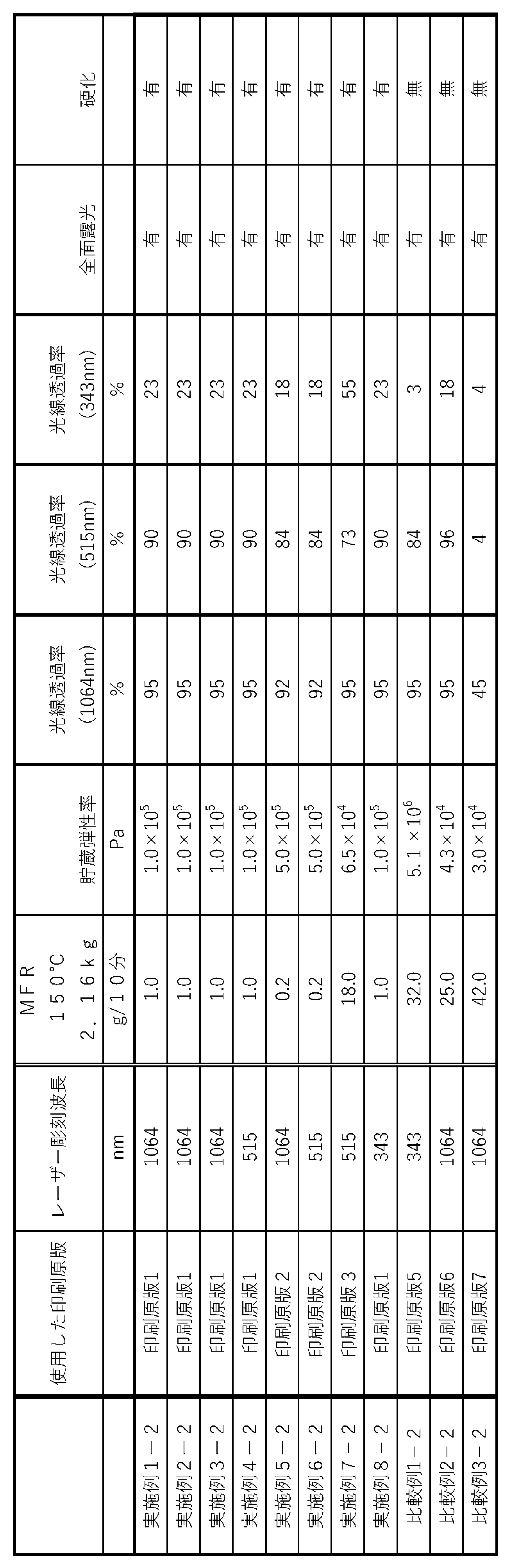
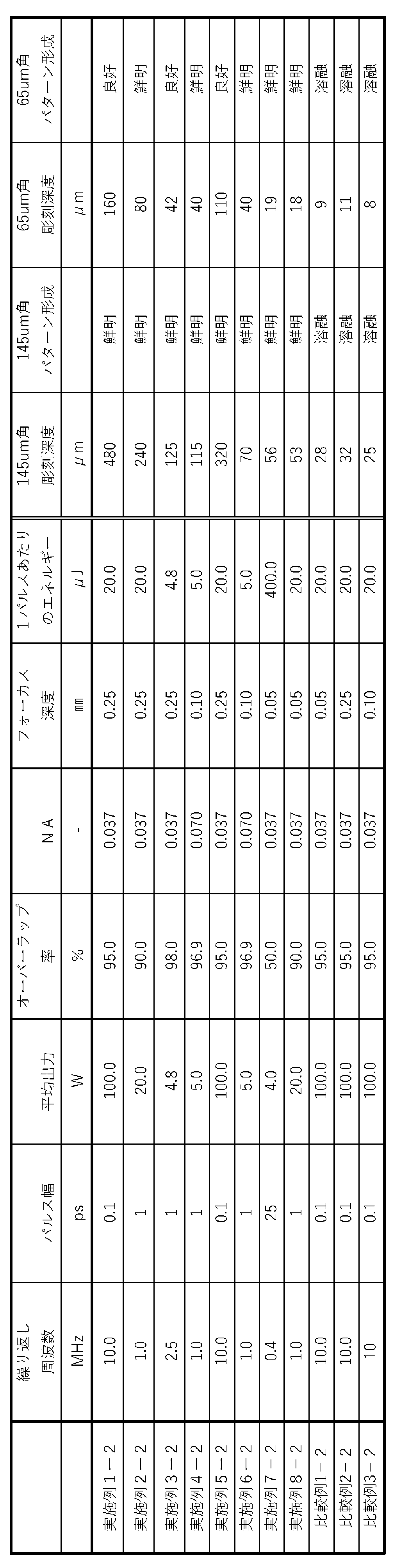
本出願は、2020年3月11日に日本国特許庁に出願された日本特許出願(特願2020-042098)に基づくものであり、その内容はここに参照として取り込まれる。
本発明の積層体及び印刷版の製造方法は、広く一般商業印刷分野において、産業上の利用可能性を有する。
Claims (21)
- 支持体、印刷原版、及び保護フィルムを有し、
前記印刷原版は、前記保護フィルムに面する側の感光性樹脂が全面的に露光され、硬化された樹脂硬化物を含む、
積層体。 - 支持体、印刷原版、及び保護フィルムを有する積層体であって、
前記印刷原版は、超短パルス発振レーザー光で凹凸パターン形成用の印刷原版である、
積層体。 - 前記印刷原版は、
140℃での貯蔵弾性率G’が、
5.00×10⁴Pa以上1.00×10⁶Pa以下である、
請求項1又は2に記載の積層体。 - 前記印刷原版のMFRが0以上20(g/10分)以下である、
請求項1乃至3のいずれか一項に記載の積層体。 - 前記印刷原版は、
超短パルス発振レーザー光で凹凸パターン形成用の印刷原版である、
請求項1乃至4のいずれか一項に記載の積層体。 - 前記印刷原版は、
前記凹凸パターン形成用の超短パルス発振レーザー光の波長において、
光線透過率が10%以上99.9%以下である、
請求項1乃至5のいずれか一項に記載の積層体。 - 前記印刷原版は、
前記凹凸パターン形成用の超短パルス発振レーザー光の波長において、
光線透過率が75%を超えて99.9%以下である、
請求項1乃至6のいずれか一項に記載の積層体。 - 前記印刷原版は、
化学放射線照射時に光分解性、光重合性、又は光架橋性を有する感光性樹脂を含む、
請求項1乃至7のいずれか一項に記載の積層体。 - 請求項1乃至8のいずれか一項に記載の積層体の前記印刷原版の表面に、
超短パルス発振レーザー光により、凹凸パターンを形成するレーザー彫刻工程を有する、
印刷版の製造方法。 - 前記印刷原版は、
140℃での貯蔵弾性率G’が、5.00×10⁴Pa以上1.00×10⁶Pa以下である、
請求項9に記載の印刷版の製造方法。 - 前記超短パルス発振レーザー光の、連続するパルス毎のオーバーラップ率が、50%以上99%以下である、
請求項9又は10に記載の印刷版の製造方法。 - 前記超短パルス発振レーザー光により、印刷原版の表面に凹凸パターンを形成する工程において、開口数(NA)が0.010以上0.100以下のレンズを用いる、
請求項9乃至11のいずれか一項に記載の印刷版の製造方法。 - 前記超短パルス発振レーザー光のフォーカス深度が、前記印刷原版の表面から25μm以上700μm以下である、
請求項9乃至12のいずれか一項に記載の印刷版の製造方法。 - 前記印刷原版は、
前記レーザー彫刻工程で用いる超短パルス発振レーザー光の波長において、
光線透過率が10%以上99.9%以下である、
請求項9乃至13のいずれか一項に記載の印刷版の製造方法。 - 前記印刷原版は、
前記レーザー彫刻工程で用いる超短パルス発振レーザー光の波長において、
光線透過率が75%を超えて99.9%以下である、
請求項9乃至14のいずれか一項に記載の印刷版の製造方法。 - 前記レーザー彫刻工程で用いる前記超短パルス発振レーザー光の、光源の平均出力が0.01W以上1000W未満である、
請求項9乃至15のいずれか一項に記載の印刷版の製造方法。 - 前記レーザー彫刻工程で用いる前記超短パルス発振レーザー光のパルス幅が、1フェムト秒以上200ナノ秒以下である、
請求項9乃至16のいずれか一項に記載の印刷版の製造方法。 - 前記レーザー彫刻工程で用いる前記超短パルス発振レーザー光の発振波長が、300nm以上1.5μm以下である、
請求項9乃至17のいずれか一項に記載の印刷版の製造方法。 - 前記レーザー彫刻工程で用いる前記超短パルス発振レーザー光の発振波長が、300nm以上700nm未満である、
請求項9乃至18のいずれか一項に記載の印刷版の製造方法。 - 前記レーザー彫刻工程で用いる前記超短パルス発振レーザー光の1パルス当たりのエネルギーが1μJ以上100kJ以下である、
請求項9乃至19のいずれか一項に記載の印刷版の製造方法。 - 前記レーザー彫刻工程で用いる前記超短パルス発振レーザー光の繰り返し周波数が20kHz以上500MH以下である、請求項9乃至20のいずれか一項に記載の印刷版の製造方法。
Priority Applications (6)
| Application Number | Priority Date | Filing Date | Title |
|---|---|---|---|
| EP21768728.4A EP4119343A4 (en) | 2020-03-11 | 2021-03-10 | LAMINATE AND METHOD OF MAKING PRINTING PLATE |
| CN202180020296.1A CN115335238A (zh) | 2020-03-11 | 2021-03-10 | 层叠体和印刷版的制造方法 |
| JP2022507240A JPWO2021182504A1 (ja) | 2020-03-11 | 2021-03-10 | |
| US17/798,704 US20230133371A1 (en) | 2020-03-11 | 2021-03-10 | Laminate and method for producing printing plate |
| JP2024077651A JP7625118B2 (ja) | 2020-03-11 | 2024-05-13 | 積層体及び印刷版の製造方法 |
| US18/675,277 US20240308201A1 (en) | 2020-03-11 | 2024-05-28 | Laminate and method for producing printing plate |
Applications Claiming Priority (2)
| Application Number | Priority Date | Filing Date | Title |
|---|---|---|---|
| JP2020-042098 | 2020-03-11 | ||
| JP2020042098 | 2020-03-11 |
Related Child Applications (2)
| Application Number | Title | Priority Date | Filing Date |
|---|---|---|---|
| US17/798,704 A-371-Of-International US20230133371A1 (en) | 2020-03-11 | 2021-03-10 | Laminate and method for producing printing plate |
| US18/675,277 Continuation US20240308201A1 (en) | 2020-03-11 | 2024-05-28 | Laminate and method for producing printing plate |
Publications (1)
| Publication Number | Publication Date |
|---|---|
| WO2021182504A1 true WO2021182504A1 (ja) | 2021-09-16 |
Family
ID=77672416
Family Applications (1)
| Application Number | Title | Priority Date | Filing Date |
|---|---|---|---|
| PCT/JP2021/009492 Ceased WO2021182504A1 (ja) | 2020-03-11 | 2021-03-10 | 積層体及び印刷版の製造方法 |
Country Status (5)
| Country | Link |
|---|---|
| US (2) | US20230133371A1 (ja) |
| EP (1) | EP4119343A4 (ja) |
| JP (2) | JPWO2021182504A1 (ja) |
| CN (1) | CN115335238A (ja) |
| WO (1) | WO2021182504A1 (ja) |
Cited By (2)
| Publication number | Priority date | Publication date | Assignee | Title |
|---|---|---|---|---|
| WO2024122603A1 (ja) * | 2022-12-07 | 2024-06-13 | 旭化成株式会社 | 印刷凹版及びその製造方法、並びに印刷方法 |
| EP4527634A4 (en) * | 2022-05-18 | 2026-02-11 | Asahi Chemical Ind | FLEXOGRAPHIC PRINTING ORIGINAL PLATE, FLEXOGRAPHIC PRINTING ORIGINAL PLATE MANUFACTURING METHOD, FLEXOGRAPHIC PRINTING PLATE AND FLEXOGRAPHIC PRINTING METHOD |
Citations (5)
| Publication number | Priority date | Publication date | Assignee | Title |
|---|---|---|---|---|
| JP2846954B2 (ja) | 1992-05-11 | 1999-01-13 | イー・アイ・デュポン・ドゥ・ヌムール・アンド・カンパニー | 単層フレキソグラフ印刷板の製造方法 |
| US8920692B2 (en) * | 2011-03-22 | 2014-12-30 | Eastman Kodak Company | Method for recycling relief image elements |
| JP2019014133A (ja) * | 2017-07-06 | 2019-01-31 | 住友ゴム工業株式会社 | フレキソ印刷版の製造方法、および液晶表示素子の製造方法 |
| JP2020029003A (ja) * | 2018-08-21 | 2020-02-27 | 住友ゴム工業株式会社 | フレキソ印刷版とそれを用いた液晶表示素子の製造方法 |
| JP2020042098A (ja) | 2018-09-07 | 2020-03-19 | コニカミノルタ株式会社 | 電子写真感光体、ならびにこれを用いた電子写真画像形成方法および電子写真像形成装置 |
Family Cites Families (23)
| Publication number | Priority date | Publication date | Assignee | Title |
|---|---|---|---|---|
| JP4472922B2 (ja) | 2000-06-15 | 2010-06-02 | スリーエム イノベイティブ プロパティズ カンパニー | 多光子光化学プロセスを使用したマルチカラー画像化 |
| US7348123B2 (en) * | 2001-04-18 | 2008-03-25 | E.I. Du Pont De Nemours And Company | Process for preparing a flexographic printing plate |
| US20050123856A1 (en) * | 2003-12-05 | 2005-06-09 | Roberts David H. | Process for the manufacture of flexographic printing plates |
| JP2006227261A (ja) | 2005-02-17 | 2006-08-31 | Dainippon Screen Mfg Co Ltd | 印刷版の製版装置 |
| US20070084369A1 (en) * | 2005-09-26 | 2007-04-19 | Jsr Corporation | Flexographic printing plate and process for production thereof |
| US20080018943A1 (en) | 2006-06-19 | 2008-01-24 | Eastman Kodak Company | Direct engraving of flexographic printing plates |
| JP5481794B2 (ja) * | 2008-03-25 | 2014-04-23 | Jsr株式会社 | レーザー加工用成形品の製造方法、レーザー加工用成形品、及びフレキソ印刷版 |
| JP5371119B2 (ja) * | 2008-09-12 | 2013-12-18 | 旭化成イーマテリアルズ株式会社 | 樹脂凸版印刷版の製造方法、樹脂凸版印刷版、及び樹脂凸版印刷版の製造装置 |
| JP2010146671A (ja) | 2008-12-19 | 2010-07-01 | Mitsubishi Chemicals Corp | 光記録再生方法及び光記録媒体 |
| JP5457955B2 (ja) * | 2010-06-28 | 2014-04-02 | 富士フイルム株式会社 | レーザー彫刻用樹脂組成物、レーザー彫刻用レリーフ印刷版原版、レーザー彫刻用レリーフ印刷版原版の製造方法、及び、レリーフ印刷版の製版方法 |
| US20120240802A1 (en) * | 2011-03-22 | 2012-09-27 | Landry-Coltrain Christine J | Laser-engraveable flexographic printing precursors |
| US20130186292A1 (en) * | 2012-01-19 | 2013-07-25 | Fujifilm Corporation | Resin composition for flexographic printing plate, laser-engraving type flexographic printing plate precursor and process for producing same, and flexographic printing plate and process for making same |
| JP5996197B2 (ja) * | 2012-01-27 | 2016-09-21 | 旭化成株式会社 | フレキソ印刷版用液状感光性樹脂組成物 |
| WO2013176040A1 (ja) * | 2012-05-21 | 2013-11-28 | 富士フイルム株式会社 | レーザー彫刻用樹脂組成物、レーザー彫刻用レリーフ印刷版原版の製造方法、レリーフ印刷版原版、レリーフ印刷版の製版方法及びレリーフ印刷版 |
| JP5904960B2 (ja) * | 2013-03-12 | 2016-04-20 | 富士フイルム株式会社 | レーザー彫刻用樹脂組成物、レーザー彫刻用フレキソ印刷版原版の製造方法、フレキソ印刷版原版、フレキソ印刷版の製版方法及びフレキソ印刷版 |
| US20150030984A1 (en) | 2013-07-26 | 2015-01-29 | Uni-Pixel Displays, Inc. | Method of manufacturing a flexographic printing plate for high-resolution printing |
| JP5752752B2 (ja) * | 2013-07-31 | 2015-07-22 | 富士フイルム株式会社 | レーザー彫刻用樹脂組成物、レーザー彫刻用フレキソ印刷版原版の製造方法、フレキソ印刷版原版、フレキソ印刷版の製版方法及びフレキソ印刷版 |
| JP2015071298A (ja) * | 2013-09-06 | 2015-04-16 | 富士フイルム株式会社 | レーザー彫刻用樹脂組成物、レーザー彫刻用フレキソ印刷版原版及びその製造方法、並びに、フレキソ印刷版及びその製版方法 |
| GB201509208D0 (en) | 2015-05-28 | 2015-07-15 | J P Imaging Ltd | Improvements relating to printing |
| DE102015009950B4 (de) | 2015-08-05 | 2019-09-19 | Hell Gravure Systems Gmbh & Co. Kg | Verfahren und Vorrichtung zur Erzeugung eines Druckbildes auf einem Druckformrohling |
| CN106543860B (zh) | 2015-09-23 | 2020-04-10 | 乐凯华光印刷科技有限公司 | 一种免处理平印版前体及超短脉冲激光制版方法 |
| ES2798799T3 (es) * | 2015-09-28 | 2020-12-14 | Toyo Boseki | Composición de resina fotosensible para una placa original de impresión en relieve y una placa original de impresión en relieve obtenida a partir de la misma |
| KR102081191B1 (ko) | 2016-06-24 | 2020-02-26 | 에이피시스템 주식회사 | 전주도금법을 이용한 미세 금속 마스크 제조방법 |
-
2021
- 2021-03-10 US US17/798,704 patent/US20230133371A1/en not_active Abandoned
- 2021-03-10 CN CN202180020296.1A patent/CN115335238A/zh active Pending
- 2021-03-10 JP JP2022507240A patent/JPWO2021182504A1/ja active Pending
- 2021-03-10 WO PCT/JP2021/009492 patent/WO2021182504A1/ja not_active Ceased
- 2021-03-10 EP EP21768728.4A patent/EP4119343A4/en active Pending
-
2024
- 2024-05-13 JP JP2024077651A patent/JP7625118B2/ja active Active
- 2024-05-28 US US18/675,277 patent/US20240308201A1/en not_active Abandoned
Patent Citations (5)
| Publication number | Priority date | Publication date | Assignee | Title |
|---|---|---|---|---|
| JP2846954B2 (ja) | 1992-05-11 | 1999-01-13 | イー・アイ・デュポン・ドゥ・ヌムール・アンド・カンパニー | 単層フレキソグラフ印刷板の製造方法 |
| US8920692B2 (en) * | 2011-03-22 | 2014-12-30 | Eastman Kodak Company | Method for recycling relief image elements |
| JP2019014133A (ja) * | 2017-07-06 | 2019-01-31 | 住友ゴム工業株式会社 | フレキソ印刷版の製造方法、および液晶表示素子の製造方法 |
| JP2020029003A (ja) * | 2018-08-21 | 2020-02-27 | 住友ゴム工業株式会社 | フレキソ印刷版とそれを用いた液晶表示素子の製造方法 |
| JP2020042098A (ja) | 2018-09-07 | 2020-03-19 | コニカミノルタ株式会社 | 電子写真感光体、ならびにこれを用いた電子写真画像形成方法および電子写真像形成装置 |
Non-Patent Citations (3)
| Title |
|---|
| "Kankousei Koubunshi", 1977, KODANSHA LTD., pages: 228 |
| "Polymer Data Handbook - Basics", 1986, BAIFUKAN CO., LTD |
| See also references of EP4119343A4 |
Cited By (3)
| Publication number | Priority date | Publication date | Assignee | Title |
|---|---|---|---|---|
| EP4527634A4 (en) * | 2022-05-18 | 2026-02-11 | Asahi Chemical Ind | FLEXOGRAPHIC PRINTING ORIGINAL PLATE, FLEXOGRAPHIC PRINTING ORIGINAL PLATE MANUFACTURING METHOD, FLEXOGRAPHIC PRINTING PLATE AND FLEXOGRAPHIC PRINTING METHOD |
| WO2024122603A1 (ja) * | 2022-12-07 | 2024-06-13 | 旭化成株式会社 | 印刷凹版及びその製造方法、並びに印刷方法 |
| JPWO2024122603A1 (ja) * | 2022-12-07 | 2024-06-13 |
Also Published As
| Publication number | Publication date |
|---|---|
| JP2024105505A (ja) | 2024-08-06 |
| EP4119343A1 (en) | 2023-01-18 |
| US20230133371A1 (en) | 2023-05-04 |
| JP7625118B2 (ja) | 2025-01-31 |
| CN115335238A (zh) | 2022-11-11 |
| US20240308201A1 (en) | 2024-09-19 |
| EP4119343A4 (en) | 2023-08-16 |
| JPWO2021182504A1 (ja) | 2021-09-16 |
Similar Documents
| Publication | Publication Date | Title |
|---|---|---|
| JP4837738B2 (ja) | 感光性樹脂組成物 | |
| EP1516745B1 (en) | Photosensitive resin composition for forming a laser engravable printing element | |
| JP7625118B2 (ja) | 積層体及び印刷版の製造方法 | |
| EP1731325A1 (en) | Hollow cylindrical printing element | |
| JPWO2003022594A1 (ja) | レーザー彫刻可能な印刷原版用感光性樹脂組成物 | |
| JP5371119B2 (ja) | 樹脂凸版印刷版の製造方法、樹脂凸版印刷版、及び樹脂凸版印刷版の製造装置 | |
| JP4493600B2 (ja) | レーザー彫刻可能な印刷基材の製造方法 | |
| JP4323186B2 (ja) | レーザー彫刻可能な円筒状フレキソ印刷原版 | |
| JP2006248191A (ja) | シート状あるいは円筒状の樹脂製印刷基材の製造方法 | |
| JP4425551B2 (ja) | レーザー彫刻可能な印刷原版用感光性樹脂組成物 | |
| JP2004174758A (ja) | レーザー彫刻印刷原版 | |
| JP2006069120A (ja) | 電子回路あるいは光学部材の製造方法 | |
| JP4502367B2 (ja) | レーザー彫刻可能な円筒状フレキソ印刷原版の製造方法 | |
| JP4942404B2 (ja) | シート状又は円筒状印刷基材の製造方法 | |
| JP4226300B2 (ja) | フレキソ印刷版の製造方法 | |
| JP4180314B2 (ja) | 印刷版の製造方法 | |
| JP2005221735A (ja) | レーザー彫刻可能な円筒状印刷原版の製造方法 | |
| JP4220272B2 (ja) | レーザー彫刻印刷版の製造方法 | |
| JP2010064281A (ja) | シート状印刷原版、シート状印刷版および、印刷原版もしくは印刷版の装着方法 | |
| JP2007144910A (ja) | レーザー彫刻印刷版の製造方法 | |
| JP2009297981A (ja) | レーザー彫刻可能な印刷原版 | |
| JP5000682B2 (ja) | レーザー彫刻可能な円筒状フレキソ印刷原版 | |
| JP2004262076A (ja) | レーザー彫刻可能なシームレス印刷原版およびその成形方法 | |
| CN120129611A (zh) | 印刷凹版及其制造方法、以及印刷方法 |
Legal Events
| Date | Code | Title | Description |
|---|---|---|---|
| 121 | Ep: the epo has been informed by wipo that ep was designated in this application |
Ref document number: 21768728 Country of ref document: EP Kind code of ref document: A1 |
|
| ENP | Entry into the national phase |
Ref document number: 2022507240 Country of ref document: JP Kind code of ref document: A |
|
| NENP | Non-entry into the national phase |
Ref country code: DE |
|
| ENP | Entry into the national phase |
Ref document number: 2021768728 Country of ref document: EP Effective date: 20221011 |