WO2021182600A1 - 情報処理装置、検査システム、プログラムおよび情報処理方法 - Google Patents
情報処理装置、検査システム、プログラムおよび情報処理方法 Download PDFInfo
- Publication number
- WO2021182600A1 WO2021182600A1 PCT/JP2021/009986 JP2021009986W WO2021182600A1 WO 2021182600 A1 WO2021182600 A1 WO 2021182600A1 JP 2021009986 W JP2021009986 W JP 2021009986W WO 2021182600 A1 WO2021182600 A1 WO 2021182600A1
- Authority
- WO
- WIPO (PCT)
- Prior art keywords
- inspection
- endoscope
- inspection image
- information processing
- unit
- Prior art date
- Legal status (The legal status is an assumption and is not a legal conclusion. Google has not performed a legal analysis and makes no representation as to the accuracy of the status listed.)
- Ceased
Links
Images









Classifications
-
- A—HUMAN NECESSITIES
- A61—MEDICAL OR VETERINARY SCIENCE; HYGIENE
- A61B—DIAGNOSIS; SURGERY; IDENTIFICATION
- A61B1/00—Instruments for performing medical examinations of the interior of cavities or tubes of the body by visual or photographical inspection, e.g. endoscopes; Illuminating arrangements therefor
- A61B1/012—Instruments for performing medical examinations of the interior of cavities or tubes of the body by visual or photographical inspection, e.g. endoscopes; Illuminating arrangements therefor characterised by internal passages or accessories therefor
- A61B1/0125—Endoscope within endoscope
-
- A—HUMAN NECESSITIES
- A61—MEDICAL OR VETERINARY SCIENCE; HYGIENE
- A61B—DIAGNOSIS; SURGERY; IDENTIFICATION
- A61B1/00—Instruments for performing medical examinations of the interior of cavities or tubes of the body by visual or photographical inspection, e.g. endoscopes; Illuminating arrangements therefor
- A61B1/00002—Operational features of endoscopes
- A61B1/00057—Operational features of endoscopes provided with means for testing or calibration
-
- A—HUMAN NECESSITIES
- A61—MEDICAL OR VETERINARY SCIENCE; HYGIENE
- A61B—DIAGNOSIS; SURGERY; IDENTIFICATION
- A61B1/00—Instruments for performing medical examinations of the interior of cavities or tubes of the body by visual or photographical inspection, e.g. endoscopes; Illuminating arrangements therefor
- A61B1/00002—Operational features of endoscopes
- A61B1/00004—Operational features of endoscopes characterised by electronic signal processing
- A61B1/00009—Operational features of endoscopes characterised by electronic signal processing of image signals during a use of endoscope
-
- A—HUMAN NECESSITIES
- A61—MEDICAL OR VETERINARY SCIENCE; HYGIENE
- A61B—DIAGNOSIS; SURGERY; IDENTIFICATION
- A61B1/00—Instruments for performing medical examinations of the interior of cavities or tubes of the body by visual or photographical inspection, e.g. endoscopes; Illuminating arrangements therefor
- A61B1/00002—Operational features of endoscopes
- A61B1/00043—Operational features of endoscopes provided with output arrangements
- A61B1/00045—Display arrangement
- A61B1/00052—Display arrangement positioned at proximal end of the endoscope body
-
- A—HUMAN NECESSITIES
- A61—MEDICAL OR VETERINARY SCIENCE; HYGIENE
- A61B—DIAGNOSIS; SURGERY; IDENTIFICATION
- A61B1/00—Instruments for performing medical examinations of the interior of cavities or tubes of the body by visual or photographical inspection, e.g. endoscopes; Illuminating arrangements therefor
- A61B1/00002—Operational features of endoscopes
- A61B1/00059—Operational features of endoscopes provided with identification means for the endoscope
-
- A—HUMAN NECESSITIES
- A61—MEDICAL OR VETERINARY SCIENCE; HYGIENE
- A61B—DIAGNOSIS; SURGERY; IDENTIFICATION
- A61B1/00—Instruments for performing medical examinations of the interior of cavities or tubes of the body by visual or photographical inspection, e.g. endoscopes; Illuminating arrangements therefor
- A61B1/12—Instruments for performing medical examinations of the interior of cavities or tubes of the body by visual or photographical inspection, e.g. endoscopes; Illuminating arrangements therefor with cooling or rinsing arrangements
- A61B1/121—Instruments for performing medical examinations of the interior of cavities or tubes of the body by visual or photographical inspection, e.g. endoscopes; Illuminating arrangements therefor with cooling or rinsing arrangements provided with means for cleaning post-use
-
- G—PHYSICS
- G01—MEASURING; TESTING
- G01N—INVESTIGATING OR ANALYSING MATERIALS BY DETERMINING THEIR CHEMICAL OR PHYSICAL PROPERTIES
- G01N21/00—Investigating or analysing materials by the use of optical means, i.e. using sub-millimetre waves, infrared, visible or ultraviolet light
- G01N21/84—Systems specially adapted for particular applications
- G01N21/88—Investigating the presence of flaws or contamination
- G01N21/95—Investigating the presence of flaws or contamination characterised by the material or shape of the object to be examined
-
- G—PHYSICS
- G01—MEASURING; TESTING
- G01N—INVESTIGATING OR ANALYSING MATERIALS BY DETERMINING THEIR CHEMICAL OR PHYSICAL PROPERTIES
- G01N21/00—Investigating or analysing materials by the use of optical means, i.e. using sub-millimetre waves, infrared, visible or ultraviolet light
- G01N21/84—Systems specially adapted for particular applications
- G01N21/88—Investigating the presence of flaws or contamination
- G01N21/95—Investigating the presence of flaws or contamination characterised by the material or shape of the object to be examined
- G01N21/954—Inspecting the inner surface of hollow bodies, e.g. bores
Definitions
- the present invention relates to an information processing device, an inspection system, a program, and an information processing method.
- An endoscope having a channel through which a treatment tool can be inserted is used for examination and treatment of luminal organs such as the digestive tract (Reference 1).
- the purpose is to provide an information processing device that can detect channel abnormalities at an early stage.
- the information processing device has an inspection image acquisition unit that acquires an inspection image taken by the inspection endoscope inserted in the channel of the endoscope to be inspected, and a judgment prediction regarding the state of the channel when the inspection image is input.
- the judgment acquisition unit that inputs the inspection image acquired by the inspection image acquisition unit to the model that outputs the output and acquires the output judgment prediction, and the output unit that outputs the inspection image and the judgment prediction in association with each other.
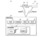
- FIG. 1 is an explanatory diagram illustrating the configuration of the inspection system 10.
- the inspection system 10 is used for inspection of the endoscope 40 to be inspected, which has been cleaned and disinfected after being used for endoscopy.
- the inspection system 10 includes an information processing device 20 and an inspection endoscope 30.
- the information processing device 20 includes a control unit 21, a main storage device 22, an auxiliary storage device 23, a communication unit 24, a display unit 26, and a bus.
- the control unit 21 is an arithmetic control device that executes the program of the present embodiment.
- One or more CPUs Central Processing Units
- GPUs Graphics Processing Units
- multi-core CPUs and the like are used for the control unit 21.
- the control unit 21 is connected to each hardware unit constituting the information processing device 20 via a bus.
- the main storage device 22 is a storage device such as SRAM (Static Random Access Memory), DRAM (Dynamic Random Access Memory), or flash memory.
- SRAM Static Random Access Memory
- DRAM Dynamic Random Access Memory
- flash memory temporary stores information necessary in the middle of processing performed by the control unit 21 and a program being executed by the control unit 21.
- the auxiliary storage device 23 is a storage device such as a SRAM, a flash memory, a hard disk, or a magnetic tape.
- the auxiliary storage device 23 stores a plurality of models 51, a program to be executed by the control unit 21, and various data necessary for executing the program.
- the communication unit 24 is an interface that performs communication between the information processing device 20 and the inspection endoscope 30 and communication between the information processing device 20 and HIS (Hospital Information System) (not shown).
- the display unit 26 is, for example, a liquid crystal display or an organic EL (Electroluminescence) display.
- the information processing device 20 is a general-purpose personal computer, tablet, smartphone, large computer, virtual machine operating on the large computer, cloud computing system, or quantum computer.
- the information processing device 20 may be a plurality of personal computers or the like that perform distributed processing.
- the information processing device 20 may be built in the inspection endoscope 30. In such a case, the communication function between the information processing device 20 and the inspection endoscope 30 is unnecessary.
- the inspection endoscope 30 includes an insertion unit 31 and an operation unit 32.
- the operation unit 32 includes a display unit 36, an operation button 35, and a grip unit 37.
- the display unit 36 is, for example, a liquid crystal display or an organic EL display.
- the inspection endoscope 30 is a so-called video endoscope having, for example, a light emitting element and an image pickup element at the tip of the insertion portion 31.
- the inspection endoscope 30 has a fiber for imaging and a fiber for illumination inside the insertion portion 31, and uses an image pickup element provided inside the operation portion 32 to display an image transmitted by the fiber for imaging. You may take a picture.
- the image sensor realizes the function of the photographing unit of the present embodiment.
- the operation buttons 35 are assigned to functions such as turning on / off the power, operating the cursor displayed on the display unit 36, starting and ending moving image recording, recording a still image, and selecting an image to be displayed on the display unit 36. ing.
- the function assigned to each operation button 35 may be appropriately set by the user.
- the inspection endoscope 30 may accept an operation by the user via voice input, wireless communication, or the like instead of the operation button 35.
- the inspection endoscope 30 includes a communication unit (not shown), and sequentially transmits images taken by the image pickup device to the information processing device 20.
- the communication unit realizes the function of the inspection image output unit of the present embodiment.
- the inspection endoscope 30 displays the display screen received from the information processing device 20 on the display unit 36.
- the inspection endoscope 30 is, for example, a general-purpose industrial endoscope having a wireless communication function.
- the inspection endoscope 30 may be dedicated to the inspection system 10 of the present embodiment.
- the control unit 21 may display the same image as the display unit 36 on the display unit 26.
- the endoscope 40 to be inspected is, for example, an endoscope for the upper gastrointestinal tract.
- the endoscope 40 to be inspected includes an operation unit 42 and an insertion unit 41.
- the channel 45 arranged inside the insertion portion 41 penetrates from the channel inlet 451 provided in the operation portion 42 to the channel outlet 452 arranged at the tip end portion of the insertion portion 41.
- the insertion portion 31 of the inspection endoscope 30 has a thickness that can be inserted into the channel 45 from the channel inlet 451 and a length that can reach the channel outlet 452. That is, the user uses the inspection endoscope 30 provided with the insertion portion 31 corresponding to the specifications of the channel 45 of the endoscope 40 to be inspected.
- the inspection endoscope 30 Even if the inspection endoscope 30 comes into contact with the inner surface of the channel 45 of the inspection endoscope 40 which has been reprocessed such as cleaning and disinfection, it is not necessary to redo the reprocess of the inspection endoscope 40. Can be cleaned. That is, the inspection endoscope 30 can be reprocessed at the same level as the inspection endoscope 40. It is desirable that the inspection endoscope 30 be reprocessed each time it is used. Since the inspection endoscope 30 does not have a channel, an air supply / water pipe, or the like, it can be easily cleaned and disinfected as compared with the inspection endoscope 40.
- the inspection endoscope 30 may be of a so-called cover type, which is covered with a clean cover each time it is used.
- the user After the endoscopy is completed, the user performs a reprocess such as cleaning and disinfection of the endoscope 40 to be inspected according to a predetermined protocol.
- the user holds the grip portion 37 in one hand and the insertion portion 31 in the other hand, and inserts the insertion portion 31 into the channel 45 while looking at the display portion 36.
- the inspection endoscope 30 takes an inspection image of the inside of the channel 45.
- the captured inspection image is displayed on the display unit 36 in real time.
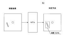
- FIG. 2 is an explanatory diagram illustrating the configuration of the model 51.
- the model 51 receives the inspection image taken by the inspection endoscope 30 and outputs a judgment prediction regarding the abnormality in the channel 45.
- a judgment prediction that the channel 45 may be broken is output in the diagonally lower left portion of the inspection image with an accuracy of 54%.
- a prediction having a certain accuracy or higher will be referred to as a “judgment result”.
- the model 51 is generated by machine learning using, for example, a large number of training data in which an inspection image and a state of a channel 45 determined by an expert observing the inspection image are combined.
- the model 51 may be a program or the like that performs image processing on the inspection image and determines the state of the channel 45 on a rule basis.
- the model 51 is created for each feature such as the use of the endoscope 40 to be inspected and the specifications of the channel 45, and is recorded in the auxiliary storage device 23.
- the model 51 may be created for each model of the endoscope 40 to be inspected.
- An example of the model 51 is shown in Table 1.
- the channel diameter means the inner diameter of the channel 45.
- the state of the channel 45 can be accurately determined by using the model 51 that differs depending on the application. For example, No. 7 and No. Since the ultrasonic endoscope of No. 8 often inserts a puncture needle into the channel 45, a scratch in the longitudinal direction is likely to occur on the inner surface of the channel 45. No. that machine learning was performed using the inspection image of the ultrasonic endoscope. 7 and No. Model 51 of 8 is trained to accurately determine longitudinal scratches.
- a model 51 is further prepared for each model of the inspection endoscope 30. It is desirable to have. This is because the appearance of the inner surface of the channel 45 may differ depending on the model of the inspection endoscope 30.
- a model 51 may be prepared for each abnormality to be detected for the endoscope 40 to be inspected having the same characteristics. For example, a model 51 for determining scratches on the channel 45 and a model 51 for determining stains may be prepared separately. It is possible to provide an inspection system 10 that accurately determines each abnormality.
- FIG. 3 is a flowchart illustrating the flow of program processing.
- the control unit 21 acquires information on the model of the endoscope 40 to be inspected, that is, endoscope information (step S501). For example, the control unit 21 receives input of information about the endoscope 40 to be inspected by a user via a microphone or a keyboard (not shown).
- the control unit 21 may read the RFID attached to the endoscope 40 to be inspected via an RFID reader (not shown) and determine the model.
- the control unit 21 may determine the model by photographing the appearance of the endoscope 40 to be inspected or the inscription attached to the endoscope 40 to be inspected by a camera (not shown).
- the control unit 21 realizes the function of the endoscope information acquisition unit of the present embodiment.
- the control unit 21 selects the model 51 corresponding to the model of the endoscope 40 to be inspected (step S502). By step S502, the control unit 21 realizes the function of the model selection unit of the present embodiment.
- the control unit 21 acquires an inspection image transmitted from the inspection endoscope 30 (step S503).
- the control unit 21 inputs the inspection image acquired in step S503 into the model 51 selected in step S502, and acquires an output determination result (step S504).
- the control unit 21 realizes the function of the determination acquisition unit of the present embodiment.
- the control unit 21 determines whether or not the determination result acquired from the model 51 includes information indicating an abnormality of the channel 45 (step S505). When the accuracy of the abnormality included in the information output from the model 51 exceeds a predetermined threshold value, the control unit 21 may determine that the information indicating the abnormality is included.
- control unit 21 determines the content of the notification to be notified to the user (step S506).
- the content of the notification is determined for each determination result by the model 51.
- Table 2 shows an example of the relationship between the judgment result and the notification content.
- Table 2 is an example, and the abnormality determined by the model 51 is not limited to the items shown in Table 2.
- the model 51 may determine, for example, buckling of the channel 45, buckling marks indicating that the channel 45 has buckled and then returned, deformation, coloring, and the like.
- the content of the notification notified to the user by the control unit 21 is not limited to the matters shown in Table 2.
- the control unit 21 may record the inspection image in which the abnormality is detected in the auxiliary storage device 23.
- the control unit 21 records the still image of the inspection image in the auxiliary storage device 23.
- the control unit 21 notifies the user of the notification content determined in step S506 (step S507).
- the notification is displayed, for example, on the display unit 36.
- the notification may be made by voice output.
- the notification may be given by vibrating the operation unit 32 or the grip unit 37.
- the control unit 21 gives a notification via the display unit 36 will be described as an example.
- control unit 21 determines whether or not to end the process (step S508). For example, the control unit 21 determines that the process is completed when the inspection endoscope 30 is removed from the channel 45. The control unit 21 may determine that the process is completed when the user operates the operation button 35 to instruct the end of the inspection.
- step S508 If it is determined that the process is not completed (NO in step S508), the control unit 21 returns to step S503. If it is determined that the process is to be completed (YES in step S508), the control unit 21 ends the process.
- the control unit 21 displays the screens illustrated in FIGS. 4 to 6 on the display unit 36 via the communication unit 24.
- the control unit 21 realizes the function of the output unit of the present embodiment by the screens illustrated in FIGS. 4 to 6.
- FIG. 4 is an example in which no abnormality is detected in the inspection image taken by the inspection endoscope 30.
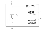
- the inspection image column 61, the determination column 64, the model of the endoscope 40 to be inspected, and the like are displayed on the screen.
- the inspection image is displayed in real time in the inspection image column 61.
- "Normal" is displayed in the determination column 64.
- FIG. 5 is an example when it is determined that the channel 45 is broken based on the inspection image.
- Notification content column 65 has been added to the screen.
- An abnormality portion frame 62 indicating a portion where an abnormality is detected is superimposed and displayed on the real-time image displayed in the inspection image column 61.
- the determination column 64 it is displayed that the determination is "break” and that the accuracy of the determination is 54%.
- the notification content column 65 the notification content corresponding to the determination result of "break" is displayed. The user can confirm that the place under observation is broken. Further, the user can confirm that the endoscope 40 to be inspected cannot be used and that repair is required promptly.
- the control unit 21 may display the accuracy of determination by the color or shape of the abnormal unit frame 62. For example, the control unit 21 displays the abnormal portion frame 62 with a thin line when the accuracy is low, and displays the abnormal portion frame 62 with a thick line when the accuracy is high.
- the control unit 21 may display the type of the detected abnormality by the color or shape of the abnormality unit frame 62. For example, the control unit 21 displays the abnormal portion frame 62 indicating the location where the breakage is detected in red, and displays the abnormal portion frame 62 indicating the location where the shallow scratch is detected in blue.
- FIG. 6 is an example in which the inspection is continued after the display of FIG. 5 is performed. No abnormality was detected in the real-time inspection image displayed in the inspection image column 61. In the determination column 64, "normal" is displayed. In the notification content column 65, the notification content displayed in FIG. 5 is displayed as it is.
- the control unit 21 displays the unique notification contents listed in the notification content column 65. By doing so, when the user moves the insertion portion 31 back and forth inside the channel 45 to observe the same place a plurality of times, it is possible to prevent the content to be displayed in the notification content column 65 from becoming too large.
- control unit 21 may notify the manufacturer of the endoscope 40 to be inspected that an abnormality has been detected.
- the control unit 21 may transmit an inspection image in which an abnormality is found, together with the notification.
- the manufacturer collects the endoscope 40 to be inspected or advances the periodic inspection time based on the notification.
- An inspection system 10 can be provided that promptly arranges necessary repairs.
- an inspection system 10 in which a user can visually confirm the internal state of the channel 45 by using the inspection endoscope 30.
- the model 51 even a user who is unfamiliar with observing the inside of the channel 45 can appropriately determine whether or not the endoscope 40 to be inspected can be continuously used.
- System 10 can be provided.
- the notification content column 65 is continuously displayed so that the user overlooks the abnormality and forgets that the abnormality has been found and is inspected.
- An inspection system 10 that prevents continuous use of the endoscope 40 can be provided.
- the inspection system 10 that prompts the user to reprocess again when a sufficient reprocess cannot be performed by the normal procedure due to a scratch or the like inside the channel 45.
- the user confirms the length of the examination endoscope 30 inserted into the channel 45, and brushes the place where the dirt remains. After that, the user puts the endoscope 40 to be inspected into the endoscope cleaning and disinfecting apparatus to perform cleaning and disinfection.
- the endoscope 40 to be inspected after the examination using the examination endoscope 30 can be used for the next endoscopy. It can be used as it is.
- an inspection system 10 capable of detecting an abnormality in the endoscope 40 to be inspected at the stage of air supply before an abnormality is found in the leak test. By detecting an abnormality at an early stage and performing appropriate repair, it is possible to provide an inspection system 10 that reduces the maintenance cost of the endoscope 40 to be inspected.
- the insertion portion 31 may be inserted into a conduit other than the channel 45, such as the air supply conduit or the water supply conduit of the endoscope 40 to be inspected.
- An inspection system 10 capable of inspecting pipelines other than the channel 45 can be provided.
- the endoscope 40 to be inspected may be a rigid mirror such as a laparoscope.
- the endoscope 40 to be inspected may be a non-medical endoscope such as an industrial endoscope.
- the present embodiment relates to an inspection system 10 that records a place where it is determined that there is an abnormality.
- the description of the parts common to the first embodiment will be omitted.
- FIG. 7 is an explanatory diagram illustrating the configuration of the inspection system 10 of the second embodiment.
- the inspection system 10 includes an information processing device 20, an inspection endoscope 30, and an advancing / retreating device 39.
- the information processing device 20 includes a control unit 21, a main storage device 22, an auxiliary storage device 23, a communication unit 24, a display unit 26, and a bus.
- the auxiliary storage device 23 records an inspection history DB 52 in addition to a plurality of models 51, a program to be executed by the control unit 21, and various data necessary for executing the program.
- the inspection history DB 52 may be recorded in an external storage device connected to the information processing device 20.
- the inspection endoscope 30 includes an insertion portion 31 and a grip portion 37.
- the inspection endoscope 30 includes a communication unit (not shown), and transmits an image captured by the image pickup device to the information processing device 20.
- the advance / retreat device 39 is an actuator that advances / retreats the insertion unit 31 based on the control signal received from the information processing device 20.
- the advancing / retreating device 39 has a mechanism for advancing / retreating the inserting portion 31 while keeping it in a clean state, and inserting / removing the inserting portion 31 into / from the channel 45.
- FIG. 8 is an explanatory diagram illustrating the record layout of the inspection history DB 52.
- the inspection history DB 52 has an S / N field, a date and time field, a position field, a determination result field, and an inspection image field.
- a serial number uniquely assigned to the endoscope 40 to be inspected is recorded.
- the date and time field the date and time when the examination of the endoscope 40 to be inspected is started is recorded.
- the position field the position of the tip of the insertion portion 31 when an abnormality is detected in the inspection image is recorded. The position is represented by, for example, the length of insertion of the insertion portion 31 from the channel inlet 451.
- the inspection image is input to the model 51 and the output judgment result is recorded.
- An inspection image is recorded in the inspection image field.
- both an inspection image on which the abnormal portion frame 62 is superimposed and an inspection image on which the abnormality portion frame 62 is not superimposed may be recorded.
- the inspection history DB 52 has one record for one abnormal location.
- FIG. 9 is a flowchart illustrating a processing flow of the program of the second embodiment.
- the control unit 21 acquires information regarding the model, serial number, and the like of the endoscope 40 to be inspected (step S511).
- the control unit 21 selects the model 51 corresponding to the model of the endoscope 40 to be inspected (step S512).
- the control unit 21 searches the inspection history DB 52 using the serial number acquired in step S511 as a key, and acquires the history of the previous inspection performed on the same endoscope 40 to be inspected (step S513).
- the control unit 21 may acquire the inspection history for a predetermined number of times or for a predetermined period, for example.
- the control unit 21 controls the advancing / retreating device 39 to start inserting the insertion unit 31 into the channel 45 (step S514).
- the advance / retreat device 39 inserts the insertion unit 31 into the channel 45 at a predetermined speed based on the instruction of the control unit 21.
- the inspection endoscope 30 transmits the captured inspection image to the control unit 21.
- the control unit 21 may sequentially instruct the advance / retreat device 39 of the insertion amount.
- the control unit 21 can determine the position where the inspection image acquired in real time is taken based on the instruction given to the advance / retreat device 39.
- the control unit 21 realizes the function of the position acquisition unit of the present embodiment in cooperation with the advance / retreat device 39.
- control unit 21 may detect a marker provided on the surface of the insertion unit 31 from an image acquired from a camera installed near the channel entrance 451 to determine the position where the inspection image is taken.
- the control unit 21 acquires an inspection image transmitted from the inspection endoscope 30 (step S515). By step S515, the control unit 21 realizes the function of the inspection image acquisition unit of the present embodiment.
- the control unit 21 inputs the inspection image acquired in step S515 into the model 51 selected in step S512, and acquires an output determination result (step S516).
- the control unit 21 determines whether or not the determination result acquired from the model 51 includes information indicating an abnormality of the channel 45 (step S517). When it is determined that the information indicating the abnormality is included (YES in step S517), the control unit 21 determines the content of the notification to be notified to the user (step S518).
- the control unit 21 creates a new record in the inspection history DB 52, and records the position when the inspection image determined to be abnormal is taken, the determination result, and the inspection image (step S519).
- the control unit 21 realizes the function of the inspection history recording unit of the present embodiment.
- the control unit 21 extracts past inspection images taken at the same or nearby positions from the history acquired in step S513 (step S520). By step S520, the control unit 21 realizes the function of the extraction unit of the present embodiment.
- the control unit 21 displays the real-time inspection image, the determination result, and the extracted past inspection image on the display unit 26 (step S521).
- control unit 21 displays the real-time inspection image and the determination result on the display unit 26 (step S522).
- step S521 or step S522 the control unit 21 determines whether or not to end the process (step S523). For example, when the insertion unit 31 reaches the channel exit 452, the control unit 21 determines that the process is completed.
- step S523 If it is determined that the process is not completed (NO in step S523), the control unit 21 returns to step S515.
- the control unit 21 controls the advancing / retreating device 39 to remove the insertion unit 31 from the channel 45 (step S524).
- step S514 and step S524 the control unit 21 realizes the function of the advance / retreat control unit of the present embodiment. After that, the control unit 21 ends the process.
- FIG. 10 and 11 are explanatory views for explaining a screen example of the second embodiment.
- FIG. 10 shows an example of a screen when it is determined that “moderate scratches” are present.
- the past information column 63 and the position column 68 are displayed on the screen.
- An abnormality part frame 62 indicating a part where an abnormality was detected is superimposed and displayed on the real-time inspection image displayed in the inspection image column 61.
- the determination column 64 it is displayed that the determination is "moderate scratch”.
- the notification content column 65 the notification content corresponding to the determination result of "break" is displayed.
- the position where the real-time inspection image was taken is displayed in the position column 68.
- the past information column 63 an inspection image taken in the past at the same position and an abnormal portion frame 62 are displayed.
- Below the past information column 63 a comparison explanation between the real-time inspection image and the inspection image taken in the past is displayed. In the example shown in FIG. 10, the detected scratch state has not changed from the past state recorded in the inspection history DB 52.
- FIG. 11 shows a display example when the data corresponding to the position where the abnormality is found is not recorded in the inspection history DB 52.
- the past information column 63 the date of the previous inspection and the fact that no abnormality is recorded at the position in the previous inspection are displayed.
- the user can easily confirm whether the discovered abnormality is an abnormality that has existed in the past or a newly discovered abnormality.
- the user can easily confirm whether or not the degree of the abnormality has progressed compared to the previous inspection.
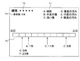
- FIG. 12 is an explanatory diagram illustrating an example of a screen for displaying a report.
- the report is created based on the inspection history DB 52.
- the control unit 21 creates a report and displays it on the display unit 26.
- the control unit 21 may transmit the created report to another computer or the like via HIS.
- Another information processing device that can access the inspection history DB 52 may display the report screen.
- a report screen may be created based on the inspection history DB 52 recorded by the plurality of inspection systems 10.
- a model column 73 indicating the model of the endoscope 40 to be inspected
- a possession number column 74 indicating the number of possessed models of the model
- a legend column 71 is displayed.
- the history column 72 is displayed below the center of the screen shown in FIG.
- the channel 45 divided into 10 equal parts in the longitudinal direction is schematically displayed.
- the right side shows the channel inlet 451 side
- the left side shows the channel exit 452 side. It is shown how many abnormalities such as "break” were detected in the past in each of the regions divided into 10 equal parts. For example, in the second region from the channel outlet 452 side, 5 cases of “shallow scratches” and 23 cases of "light stains” are detected.
- the display of the history column 72 is an example.
- the relationship between the position and the number of detected cases may be displayed by using a bar graph, a line graph, or the like.
- Information on cases in which the endoscope 40 to be examined was used in each endoscopy may be obtained from HIS, and a report may be created for each procedure such as the presence or absence of a biopsy. The report may be produced for each physician who performed the endoscopy or for each medical staff who performed the cleaning operation.
- an inspection system 10 that creates a report summarizing information on a place where an abnormality is likely to occur in the endoscope 40 to be inspected or a procedure.
- the user can consider measures to prevent damage to the endoscope 40 to be inspected by using the report of the present embodiment.
- the report may be provided to the manufacturer of the endoscope 40 to be inspected. Manufacturers can use the report to develop an endoscope 40 that is not easily damaged.
- the present embodiment relates to an inspection system 10 incorporated in an endoscope cleaning and disinfecting apparatus.
- the description of the parts common to the second embodiment will be omitted.
- the endoscope cleaning and disinfecting device is a device that automatically cleans and disinfects the endoscope. Since the endoscope cleaning and disinfecting device is known, the details thereof will be omitted.
- the inspection endoscope 30 and the advancing / retreating device 39 are attached to the cleaning tank of the endoscope cleaning / disinfecting device.
- the inspection endoscope 30 and the advancing / retreating device 39 may be cleaned and disinfected at the same time as the inspection endoscope 40. By doing so, it is possible to prevent contamination of the endoscope 40 to be inspected by the endoscope 30 for inspection.
- the information processing device 20 also serves as a control unit for the endoscope cleaning and disinfecting device. That is, the control unit 21 of the present embodiment has a function of a cleaning device control unit that controls the endoscope cleaning and disinfecting device.
- the person in charge such as a nurse or an endoscopist will perform bedside cleaning and manual cleaning of the endoscope 40 to be inspected.
- the person in charge sets the endoscope 40 to be inspected in the endoscope cleaning and disinfecting device.
- the control unit 21 controls the endoscope cleaning and disinfecting device to clean and disinfect the endoscope 40 to be inspected.
- control unit 21 After cleaning and disinfection are completed, the control unit 21 inserts the insertion unit 31 into the channel 45 to perform an inspection. If there is light dirt that can be removed by cleaning and disinfecting again, the control unit 21 controls the endoscope cleaning and disinfecting device to perform cleaning and disinfecting again.
- a camera that photographs the vicinity of the channel exit 452 of the set endoscope 40 to be inspected may be installed in the washing tank. Based on the image captured by the camera, the control unit 21 can detect that the insertion unit 31 has reached the channel exit 452.
- the control unit 21 can detect that the insertion unit 31 has reached the channel exit 452.
- a camera capable of taking a higher resolution image than the inspection endoscope 30 in addition to the state of the channel 45, for example, the cleaning state of the observation optical system, the illumination optical system, the riser, etc. can be accurately determined.
- a capable inspection system 10 can be provided.
- FIG. 13 is a flowchart illustrating a processing flow of the program of the fourth embodiment.
- the control unit 21 acquires information regarding the model of the endoscope 40 to be inspected (step S531).
- the control unit 21 selects the model 51 corresponding to the model of the endoscope 40 to be inspected (step S532).
- the control unit 21 operates an endoscope cleaning and disinfecting device to clean and disinfect the endoscope 40 to be inspected (step S533).
- the control unit 21 controls the advance / retreat device 39 to start inserting the insertion unit 31 into the channel 45 (step S534).
- the control unit 21 acquires an inspection image transmitted from the inspection endoscope 30 (step S535).
- the control unit 21 inputs the inspection image acquired in step S535 into the model 51 selected in step S532, and acquires an output determination result (step S536).
- the control unit 21 determines whether or not the determination result acquired from the model 51 includes information indicating an abnormality of the channel 45 (step S537). When it is determined that the information indicating the abnormality is included (YES in step S537), the control unit 21 creates a new record in the inspection history DB 52, and when the inspection image determined to be abnormal is taken. The position of the above, the determination result, and the inspection image are recorded (step S538).
- step S537 When it is determined that the information indicating the abnormality is not included (NO in step S537), or after the end of step S538, the control unit 21 determines whether or not the inspection of the channel 45 is completed (step S539). If it is determined that the inspection has not been completed (NO in step S539), the control unit 21 returns to step S535.
- control unit 21 controls the advancing / retreating device 39 to remove the insertion unit 31 from the channel 45 (step S540).
- the control unit 21 determines whether or not to perform re-cleaning based on the determination result recorded in the inspection history DB 52 in step S538.
- control unit 21 determines that rewashing is to be performed. If the re-cleaning has already been repeated a predetermined number of times, the control unit 21 determines that the re-cleaning is not performed.
- step S541 If it is determined that re-cleaning is to be performed (YES in step S541), the control unit 21 returns to step S533. When it is determined that re-cleaning is not performed (NO in step S541), the control unit 21 displays the reprocess result on the display unit 26 which also serves as the operation panel of the endoscope disinfection cleaning device (step S542). After that, the control unit 21 ends the process.
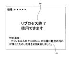
- FIG. 14 is an explanatory diagram illustrating a screen example of the fourth embodiment.
- FIG. 14 is an example of a screen displayed by the control unit 21 in step S542.
- a result column 66 showing the result of the reprocess is displayed in the center of the screen.
- a special note column 67 is displayed at the bottom of the screen.
- step S541 the control unit 21 determined that re-cleaning was necessary due to "light dirt" (YES in step S541), and performed the second cleaning. Since "light dirt" was not detected in the second step S541, the control unit 21 displayed the screen shown in FIG. 14 (step S542) and ended the process.
- the person in charge takes out the endoscope 40 to be inspected from the endoscope cleaning and disinfecting device after confirming the screen shown in FIG. If it is displayed that the endoscope 40 to be inspected cannot be used due to "breakage" or the like, the person in charge takes out the endoscope 40 to be inspected and arranges repairs.
- an endoscope cleaning and disinfecting apparatus that performs cleaning and disinfection according to the endoscope 40 to be inspected, which has a small degree of dirt, and automatically repeats cleaning as needed. It is possible to provide an endoscope cleaning and disinfecting apparatus and an inspection system 10 that reduce damage caused by a disinfectant solution or the like to the endoscope 40 to be inspected.
- control unit 21 may notify the person in charge that the manual cleaning needs to be performed again. For example, the control unit 21 notifies that manual cleaning is necessary when “moderate dirt” remains, and automatically cleans when only “light dirt” remains. repeat.
- the model 51 may be learned to output whether it is a stain that can be removed by re-cleaning with an endoscope cleaning and disinfecting device or a stain that requires manual cleaning.
- FIG. 15 is an explanatory diagram showing the configuration of the inspection system 10 of the fifth embodiment. The description of the parts common to the first embodiment will be omitted.
- the inspection system 10 of this embodiment includes a computer 90.
- the computer 90 includes a control unit 21, a main storage device 22, an auxiliary storage device 23, a communication unit 24, a display unit 26, a reading unit 28, and a bus.
- the computer 90 is an information device such as a general-purpose personal computer, a tablet, or a server computer.
- Program 97 is recorded on the portable recording medium 96.
- the control unit 21 reads the program 97 via the reading unit 28 and stores it in the auxiliary storage device 23.
- the control unit 21 may read the program 97 stored in the semiconductor memory 98 such as the flash memory mounted in the computer 90.
- the control unit 21 may download the program 97 from the communication unit 24 and another server computer (not shown) connected via a network (not shown) and store the program 97 in the auxiliary storage device 23.
- the program 97 is installed as a control program of the computer 90, loaded into the main storage device 22, and executed. As a result, the computer 90 functions as the information processing device 20 described above.
- FIG. 16 is a functional block diagram of the information processing device 20 according to the sixth embodiment.
- the information processing device 20 has an inspection image acquisition unit 81 that acquires an inspection image taken by the inspection endoscope 30 inserted in the channel 45 of the endoscope 40 to be inspected, and a channel when the inspection image is input.
- the judgment acquisition unit 82 that inputs the inspection image acquired by the inspection image acquisition unit 81 to the model 51 that outputs the judgment prediction regarding the state of 45 and acquires the output judgment prediction, the inspection image, and the judgment prediction It includes an output unit 83 that outputs in association with each other.
- Inspection system 20 Information processing device 21 Control unit 22 Main storage device 23 Auxiliary storage device 24 Communication unit 26 Display unit 28 Reading unit 30 Inspection endoscope 31 Insertion unit 32 Operation unit 35 Operation button 36 Display unit 37 Grip unit 39 Advance / retreat Equipment 40 Endoscope to be inspected 41 Insertion part 42 Operation part 45 Channel 451 Channel entrance 452 Channel exit 51 Model 52 Inspection history DB 61 Inspection image column 62 Abnormal part frame 63 Past information column 64 Judgment column 65 Notification content column 66 Result column 67 Special notes column 68 Position column 71 Legend column 72 History column 73 Model column 74 Owned number column 81 Inspection image acquisition section 82 Judgment acquisition Unit 83 Output unit 90 Computer 96 Portable recording medium 97 Program 98 Semiconductor memory
Landscapes
- Health & Medical Sciences (AREA)
- Life Sciences & Earth Sciences (AREA)
- Surgery (AREA)
- Engineering & Computer Science (AREA)
- General Health & Medical Sciences (AREA)
- Physics & Mathematics (AREA)
- Pathology (AREA)
- Medical Informatics (AREA)
- Public Health (AREA)
- Optics & Photonics (AREA)
- Biomedical Technology (AREA)
- Heart & Thoracic Surgery (AREA)
- Nuclear Medicine, Radiotherapy & Molecular Imaging (AREA)
- Molecular Biology (AREA)
- Animal Behavior & Ethology (AREA)
- Biophysics (AREA)
- Radiology & Medical Imaging (AREA)
- Veterinary Medicine (AREA)
- Signal Processing (AREA)
- Chemical & Material Sciences (AREA)
- Analytical Chemistry (AREA)
- Biochemistry (AREA)
- General Physics & Mathematics (AREA)
- Immunology (AREA)
- Endoscopes (AREA)
- Investigating Materials By The Use Of Optical Means Adapted For Particular Applications (AREA)
Abstract
Description
図1は、検査システム10の構成を説明する説明図である。検査システム10は、内視鏡検査に使用した後、洗浄および消毒を行なった被検査内視鏡40の検査に使用される。検査システム10は、情報処理装置20および検査用内視鏡30を含む。


本実施の形態は、異常があると判定した場所を記録する検査システム10に関する。実施の形態1と共通する部分については、説明を省略する。
本実施の形態は、検査履歴DB52に記録されたデータに基づいてレポートを表示する検査システム10を示す。実施の形態1と共通する部分については、説明を省略する。
本実施の形態は、内視鏡洗浄消毒装置に組み込まれた検査システム10に関する。実施の形態2と共通する部分については、説明を省略する。内視鏡洗浄消毒装置は、内視鏡の洗浄および消毒を自動的に行なう装置である。内視鏡洗浄消毒装置は公知であるため、詳細については説明を省略する。
本実施の形態は、汎用のコンピュータ90とプログラム97とを組み合わせて動作させることにより、本実施の形態の検査システム10を実現する形態に関する。図15は、実施の形態5の検査システム10の構成を示す説明図である。実施の形態1と共通する部分については、説明を省略する。
図16は、実施の形態6の情報処理装置20の機能ブロック図である。情報処理装置20は、被検査内視鏡40のチャンネル45に挿入された検査用内視鏡30により撮影された検査画像を取得する検査画像取得部81と、検査画像が入力された場合にチャンネル45の状態に関する判定予測を出力するモデル51に、検査画像取得部81が取得した検査画像を入力して、出力される判定予測を取得する判定取得部82と、検査画像と、判定予測とを関連づけて出力する出力部83とを備える。
今回開示された実施の形態はすべての点で例示であって、制限的なものでは無いと考えられるべきである。本発明の範囲は、上記した意味では無く、請求の範囲によって示され、請求の範囲と均等の意味および範囲内でのすべての変更が含まれることが意図される。
20 情報処理装置
21 制御部
22 主記憶装置
23 補助記憶装置
24 通信部
26 表示部
28 読取部
30 検査用内視鏡
31 挿入部
32 操作部
35 操作ボタン
36 表示部
37 把持部
39 進退装置
40 被検査内視鏡
41 挿入部
42 操作部
45 チャンネル
451 チャンネル入口
452 チャンネル出口
51 モデル
52 検査履歴DB
61 検査画像欄
62 異常部枠
63 過去情報欄
64 判定欄
65 通知内容欄
66 結果欄
67 特記事項欄
68 位置欄
71 凡例欄
72 履歴欄
73 機種欄
74 保有数欄
81 検査画像取得部
82 判定取得部
83 出力部
90 コンピュータ
96 可搬型記録媒体
97 プログラム
98 半導体メモリ
Claims (15)
- 被検査内視鏡のチャンネルに挿入された検査用内視鏡により撮影された検査画像を取得する検査画像取得部と、
検査画像が入力された場合にチャンネルの状態に関する判定予測を出力するモデルに、前記検査画像取得部が取得した検査画像を入力して、出力される判定予測を取得する判定取得部と、
前記検査画像と、前記判定予測とを関連づけて出力する出力部と
を備える情報処理装置。 - 前記検査画像が撮影された位置を取得する位置取得部を備え、
前記出力部は、前記検査画像と、前記判定予測と、前記位置取得部が取得した位置とを関連づけて出力する
請求項1に記載の情報処理装置。 - 前記検査画像と、前記判定予測と、前記位置取得部が取得した位置とを関連づけて記録する検査履歴記録部と、
前記位置取得部が取得した位置に対応する過去の判定予測を前記検査履歴記録部が記録した記録から抽出する抽出部とを備え、
前記判定取得部が取得した判定予測と、前記抽出部が抽出した過去の判定予測とを関連づけて出力する
請求項2に記載の情報処理装置。 - 前記位置は、前記チャンネルの入り口からの長さである
請求項3に記載の情報処理装置。 - 被検査内視鏡に関する内視鏡情報を取得する内視鏡情報取得部と、
複数のモデルから、前記内視鏡情報に対応するモデルを選択するモデル選択部とを備える
請求項1から請求項4のいずれか一つに記載の情報処理装置。 - 前記モデルは、被検査内視鏡の用途ごとに存在する
請求項5に記載の情報処理装置。 - 前記モデルは、前記チャンネルの内径ごとに存在する
請求項5または請求項6に記載の情報処理装置。 - 前記判定予測は、修理の要否に関する予測および洗浄の要否に関する予測を含む
請求項1から請求項7のいずれか一つに記載の情報処理装置。 - 前記チャンネルに挿入された前記検査用内視鏡の挿入部を進退させる進退装置を制御する進退制御部を備える
請求項1から請求項8のいずれか一つに記載の情報処理装置。 - 検査用内視鏡と、情報処理装置とを備える検査システムにおいて
前記検査用内視鏡は、
被検査内視鏡のチャンネルに挿入されて、検査画像を撮影する撮影部と、
前記検査画像を出力する検査画像出力部とを有し、
前記情報処理装置は、
前記検査画像出力部から出力された検査画像を取得する検査画像取得部と、
検査画像が入力された場合にチャンネルの状態に関する判定予測を出力するモデルに、前記検査画像取得部が取得した検査画像を入力して、出力される判定予測を取得する判定取得部と、
前記検査画像と、前記判定予測とを関連づけて出力する出力部と
を備える検査システム。 - 前記チャンネルに挿入された前記検査用内視鏡の挿入部を進退させる進退装置を備える
請求項10に記載の検査システム。 - 前記情報処理装置は、
前記被検査内視鏡を洗浄する洗浄装置を制御する洗浄装置制御部を備え、
前記判定予測が、前記被検査内視鏡の再洗浄が必要であることを示す場合、前記洗浄装置に再洗浄を行なわせる
請求項10または請求項11に記載の検査システム。 - 前記検査用内視鏡は、前記被検査内視鏡と共に前記洗浄装置で洗浄される
請求項12に記載の検査システム。 - 被検査内視鏡のチャンネルに挿入された検査用内視鏡により撮影された検査画像を取得
する検査画像取得部と、
検査画像が入力された場合にチャンネルの状態に関する判定予測を出力するモデルに、取得した検査画像を入力して、出力される判定予測を取得し、
前記検査画像と、前記判定予測とを関連づけて出力する
処理をコンピュータに実行させるプログラム。 - 被検査内視鏡のチャンネルに挿入された検査用内視鏡により撮影された検査画像を取得し、
検査画像が入力された場合にチャンネルの状態に関する判定予測を出力するモデルに、取得した検査画像を入力して、出力される判定予測を取得し、
前記検査画像と、前記判定予測とを関連づけて出力する
処理をコンピュータに実行させる情報処理方法。
Priority Applications (4)
| Application Number | Priority Date | Filing Date | Title |
|---|---|---|---|
| CN202180019513.5A CN115280138A (zh) | 2020-03-12 | 2021-03-12 | 信息处理装置、检查系统、程序以及信息处理方法 |
| US17/910,524 US12329353B2 (en) | 2020-03-12 | 2021-03-12 | Endoscope channel information processing device, endoscope channel inspection system, and endoscope channel information processing method |
| EP21767767.3A EP4119933A4 (en) | 2020-03-12 | 2021-03-12 | INFORMATION PROCESSING DEVICE, INSPECTION SYSTEM, PROGRAM AND INFORMATION PROCESSING METHOD |
| JP2022507296A JP7313542B2 (ja) | 2020-03-12 | 2021-03-12 | 情報処理装置、検査システム、プログラムおよび情報処理方法 |
Applications Claiming Priority (2)
| Application Number | Priority Date | Filing Date | Title |
|---|---|---|---|
| US202062988495P | 2020-03-12 | 2020-03-12 | |
| US62/988,495 | 2020-03-12 |
Publications (1)
| Publication Number | Publication Date |
|---|---|
| WO2021182600A1 true WO2021182600A1 (ja) | 2021-09-16 |
Family
ID=77671661
Family Applications (1)
| Application Number | Title | Priority Date | Filing Date |
|---|---|---|---|
| PCT/JP2021/009986 Ceased WO2021182600A1 (ja) | 2020-03-12 | 2021-03-12 | 情報処理装置、検査システム、プログラムおよび情報処理方法 |
Country Status (5)
| Country | Link |
|---|---|
| US (1) | US12329353B2 (ja) |
| EP (1) | EP4119933A4 (ja) |
| JP (1) | JP7313542B2 (ja) |
| CN (1) | CN115280138A (ja) |
| WO (1) | WO2021182600A1 (ja) |
Cited By (2)
| Publication number | Priority date | Publication date | Assignee | Title |
|---|---|---|---|---|
| JP2023129970A (ja) * | 2022-03-07 | 2023-09-20 | セイコーエプソン株式会社 | 印刷画像の欠陥判別装置、およびその判別方法 |
| WO2024092063A1 (en) * | 2022-10-25 | 2024-05-02 | Clarus Medical, Llc | Medical device inspection system |
Families Citing this family (2)
| Publication number | Priority date | Publication date | Assignee | Title |
|---|---|---|---|---|
| US20240029227A1 (en) * | 2022-07-19 | 2024-01-25 | Qualcomm Incorporated | Screen defect and contamination detection for mobile devices |
| FR3145470B1 (fr) | 2023-02-06 | 2025-01-31 | Axess Vision Tech | Procédé pour déterminer si le canal opérateur d’un endoscope médical a été utilisé |
Citations (7)
| Publication number | Priority date | Publication date | Assignee | Title |
|---|---|---|---|---|
| JP2007147506A (ja) * | 2005-11-29 | 2007-06-14 | Fujifilm Corp | 配管検査システム及びそれに用いる自走式配管検査装置 |
| JP2012013675A (ja) * | 2010-05-31 | 2012-01-19 | Tohoku Electric Power Co Inc | 鋼管内部腐食解析装置及び腐食解析方法 |
| US20140150782A1 (en) * | 2012-12-04 | 2014-06-05 | Endoclear Llc | Closed suction cleaning devices, systems and methods |
| US20180067051A1 (en) * | 2013-02-26 | 2018-03-08 | Steris Inc. | Method and apparatus for optical detection of bio-contaminants within a lumen |
| WO2019102679A1 (ja) | 2017-11-21 | 2019-05-31 | オリンパス株式会社 | 内視鏡の先端部および内視鏡 |
| WO2019219955A1 (en) * | 2018-05-18 | 2019-11-21 | Ab Sandvik Materials Technology | Tube inspection system |
| WO2020096891A1 (en) * | 2018-11-05 | 2020-05-14 | Medivators Inc. | Self-centering mechanism |
Family Cites Families (9)
| Publication number | Priority date | Publication date | Assignee | Title |
|---|---|---|---|---|
| JP3920907B2 (ja) | 2006-04-03 | 2007-05-30 | オリンパス株式会社 | 傷検査装置および傷検査装置を備えた内視鏡装置 |
| EP2552293B1 (en) * | 2010-03-29 | 2015-01-07 | Endoclear LLC | Airway cleaning and visualization |
| JP5568196B1 (ja) * | 2012-10-18 | 2014-08-06 | オリンパスメディカルシステムズ株式会社 | 画像処理装置及び画像処理方法 |
| US20170323163A1 (en) * | 2016-05-06 | 2017-11-09 | City Of Long Beach | Sewer pipe inspection and diagnostic system and method |
| US10709313B2 (en) | 2016-09-21 | 2020-07-14 | NCI, Inc. | Surgical instrument inspection system |
| US11559597B2 (en) * | 2018-01-23 | 2023-01-24 | Clarus Medical, Llc | Medical device inspection system |
| US20190269468A1 (en) * | 2018-03-01 | 2019-09-05 | Auris Health, Inc. | Methods and systems for mapping and navigation |
| US11715558B2 (en) * | 2019-06-25 | 2023-08-01 | Bh2 Innovations Inc. | Systems and methods for detecting defects in medical devices |
| CN110613417A (zh) * | 2019-09-24 | 2019-12-27 | 浙江同花顺智能科技有限公司 | 一种输出上消化内镜操作信息的方法、设备及存储介质 |
-
2021
- 2021-03-12 WO PCT/JP2021/009986 patent/WO2021182600A1/ja not_active Ceased
- 2021-03-12 EP EP21767767.3A patent/EP4119933A4/en active Pending
- 2021-03-12 CN CN202180019513.5A patent/CN115280138A/zh active Pending
- 2021-03-12 JP JP2022507296A patent/JP7313542B2/ja active Active
- 2021-03-12 US US17/910,524 patent/US12329353B2/en active Active
Patent Citations (7)
| Publication number | Priority date | Publication date | Assignee | Title |
|---|---|---|---|---|
| JP2007147506A (ja) * | 2005-11-29 | 2007-06-14 | Fujifilm Corp | 配管検査システム及びそれに用いる自走式配管検査装置 |
| JP2012013675A (ja) * | 2010-05-31 | 2012-01-19 | Tohoku Electric Power Co Inc | 鋼管内部腐食解析装置及び腐食解析方法 |
| US20140150782A1 (en) * | 2012-12-04 | 2014-06-05 | Endoclear Llc | Closed suction cleaning devices, systems and methods |
| US20180067051A1 (en) * | 2013-02-26 | 2018-03-08 | Steris Inc. | Method and apparatus for optical detection of bio-contaminants within a lumen |
| WO2019102679A1 (ja) | 2017-11-21 | 2019-05-31 | オリンパス株式会社 | 内視鏡の先端部および内視鏡 |
| WO2019219955A1 (en) * | 2018-05-18 | 2019-11-21 | Ab Sandvik Materials Technology | Tube inspection system |
| WO2020096891A1 (en) * | 2018-11-05 | 2020-05-14 | Medivators Inc. | Self-centering mechanism |
Non-Patent Citations (1)
| Title |
|---|
| See also references of EP4119933A4 |
Cited By (2)
| Publication number | Priority date | Publication date | Assignee | Title |
|---|---|---|---|---|
| JP2023129970A (ja) * | 2022-03-07 | 2023-09-20 | セイコーエプソン株式会社 | 印刷画像の欠陥判別装置、およびその判別方法 |
| WO2024092063A1 (en) * | 2022-10-25 | 2024-05-02 | Clarus Medical, Llc | Medical device inspection system |
Also Published As
| Publication number | Publication date |
|---|---|
| JP7313542B2 (ja) | 2023-07-24 |
| US20230138418A1 (en) | 2023-05-04 |
| CN115280138A (zh) | 2022-11-01 |
| EP4119933A1 (en) | 2023-01-18 |
| US12329353B2 (en) | 2025-06-17 |
| JPWO2021182600A1 (ja) | 2021-09-16 |
| EP4119933A4 (en) | 2024-04-17 |
Similar Documents
| Publication | Publication Date | Title |
|---|---|---|
| JP7313542B2 (ja) | 情報処理装置、検査システム、プログラムおよび情報処理方法 | |
| US12245904B2 (en) | Endoscope cleaning and inspection system and method | |
| CN112533525B (zh) | 内窥镜用处理器、信息处理装置、程序、信息处理方法以及学习模型的生成方法 | |
| JP7203000B2 (ja) | プログラム、情報処理方法及び情報処理装置 | |
| JP4009583B2 (ja) | 医療用画像記録システム | |
| JP7189355B2 (ja) | コンピュータプログラム、内視鏡用プロセッサ、及び情報処理方法 | |
| CN102789602A (zh) | 清洗管理方法、装置和内窥镜管理系统 | |
| JP2021037113A (ja) | 内視鏡用プロセッサおよび学習モデルの生成方法 | |
| US20240122444A1 (en) | Endoscopic examination support apparatus, endoscopic examination support method, and recording medium | |
| US12357420B2 (en) | Cleaning support system, processing apparatus, and cleaning support method | |
| US20260108136A1 (en) | Endoscopic examination support apparatus, endoscopic examination support method, and recording medium | |
| US12573138B2 (en) | Endoscopic examination support apparatus, endoscopic examination support method, and recording medium | |
| US20240148235A1 (en) | Information processing apparatus, information processing method, endoscope system, and report creation support device | |
| JP2021015313A (ja) | 内視鏡管理装置 | |
| JP5872976B2 (ja) | 医療画像管理装置 | |
| US20230115087A1 (en) | Provisioning system for endoscopes | |
| WO2023089716A1 (ja) | 情報表示装置、情報表示方法、及び、記録媒体 | |
| WO2024121886A1 (ja) | 内視鏡検査支援装置、内視鏡検査支援方法、及び、記録媒体 | |
| JP7329392B2 (ja) | 内視鏡リプロセス支援装置、内視鏡リプロセス支援方法およびプログラム | |
| WO2023218523A1 (ja) | 第2の内視鏡システム、第1の内視鏡システム、および内視鏡検査方法 | |
| WO2024121885A1 (ja) | 情報処理装置、情報処理方法、及び、記録媒体 | |
| CN118434345A (zh) | 医疗辅助系统、医疗辅助方法以及存储介质 | |
| JP2024083943A (ja) | 内視鏡リプロセス支援システム、内視鏡リプロセス支援方法、および内視鏡リプロセス支援プログラム | |
| WO2024171780A1 (ja) | 医療支援装置、内視鏡、医療支援方法、及びプログラム | |
| CN119889631A (zh) | 医疗信息处理装置 |
Legal Events
| Date | Code | Title | Description |
|---|---|---|---|
| 121 | Ep: the epo has been informed by wipo that ep was designated in this application |
Ref document number: 21767767 Country of ref document: EP Kind code of ref document: A1 |
|
| ENP | Entry into the national phase |
Ref document number: 2022507296 Country of ref document: JP Kind code of ref document: A |
|
| NENP | Non-entry into the national phase |
Ref country code: DE |
|
| ENP | Entry into the national phase |
Ref document number: 2021767767 Country of ref document: EP Effective date: 20221012 |
|
| WWG | Wipo information: grant in national office |
Ref document number: 17910524 Country of ref document: US |