WO2021186861A1 - 累進屈折力レンズおよびその設計方法 - Google Patents
累進屈折力レンズおよびその設計方法 Download PDFInfo
- Publication number
- WO2021186861A1 WO2021186861A1 PCT/JP2021/000680 JP2021000680W WO2021186861A1 WO 2021186861 A1 WO2021186861 A1 WO 2021186861A1 JP 2021000680 W JP2021000680 W JP 2021000680W WO 2021186861 A1 WO2021186861 A1 WO 2021186861A1
- Authority
- WO
- WIPO (PCT)
- Prior art keywords
- power
- distance
- astigmatism
- astigmatic
- degrees
- Prior art date
- Legal status (The legal status is an assumption and is not a legal conclusion. Google has not performed a legal analysis and makes no representation as to the accuracy of the status listed.)
- Ceased
Links
Images




Classifications
-
- G—PHYSICS
- G02—OPTICS
- G02C—SPECTACLES; SUNGLASSES OR GOGGLES INSOFAR AS THEY HAVE THE SAME FEATURES AS SPECTACLES; CONTACT LENSES
- G02C7/00—Optical parts
- G02C7/02—Lenses; Lens systems ; Methods of designing lenses
- G02C7/024—Methods of designing ophthalmic lenses
- G02C7/028—Special mathematical design techniques
-
- G—PHYSICS
- G02—OPTICS
- G02C—SPECTACLES; SUNGLASSES OR GOGGLES INSOFAR AS THEY HAVE THE SAME FEATURES AS SPECTACLES; CONTACT LENSES
- G02C7/00—Optical parts
- G02C7/02—Lenses; Lens systems ; Methods of designing lenses
- G02C7/024—Methods of designing ophthalmic lenses
- G02C7/027—Methods of designing ophthalmic lenses considering wearer's parameters
-
- G—PHYSICS
- G02—OPTICS
- G02C—SPECTACLES; SUNGLASSES OR GOGGLES INSOFAR AS THEY HAVE THE SAME FEATURES AS SPECTACLES; CONTACT LENSES
- G02C7/00—Optical parts
- G02C7/02—Lenses; Lens systems ; Methods of designing lenses
- G02C7/06—Lenses; Lens systems ; Methods of designing lenses bifocal; multifocal ; progressive
- G02C7/061—Spectacle lenses with progressively varying focal power
- G02C7/063—Shape of the progressive surface
Definitions
- the present invention relates to a progressive power lens and a design method thereof.
- Patent Document 1 describes a method for setting the astigmatic power and the astigmatic axis at two different object distances (distance portion and near portion) (for example, claim 1).
- Patent Document 1 sets the spherical power, the astigmatic power and the astigmatic axis at two different object distances, and the spherical power, the astigmatic power and the astigmatic axis are determined as a function of the object distance ([009] of Patent Document 1]. ).
- Patent Document 1 does not disclose a specific method for developing various mathematical formulas on the surface of a progressive power lens.
- An embodiment of the present invention aims to provide a technique capable of freely setting an astigmatic power and an astigmatic axis suitable for near vision.
- the first aspect of the present invention is A lower near portion with a near vision value for near vision and an upper distance portion with a distance prescription value for far vision looking at a distance farther than the near distance. And an intermediate part whose frequency changes so as to connect the distance part and the near part, Spherical dioptric power S F , astigmatism dioptric power CF and astigmatism axis Ax F , which are the distance prescription values required for distance vision, are set in the distance portion, and near vision is required in the near vision portion.
- a curvature distribution which increases in the combined state, a C N and Ax N is achieved, the progressive addition lens in
- the second aspect of the present invention is the aspect described in the first aspect.
- the set ⁇ has one astigmatic axis Ax ⁇ , has a distribution in which the spherical power is increased from zero D to the spherical power S ⁇ , and is increased from the astigmatic power zero D to the astigmatic power C ⁇ .
- S ⁇ , C ⁇ and Ax ⁇ are determined by the following procedure. [Procedure 1]
- the distance prescription value of the distance portion is vector-subtracted from the near-distance prescription value of the near portion, and the spherical power S ⁇ 1 , the astigmatism power C ⁇ 1 and the astigmatism axis Ax ⁇ 1 are calculated.
- S ⁇ 1 and C ⁇ 1 are converted to a state in which the value of the astigmatic axis Ax ⁇ 1 is replaced with the value in the increasing / decreasing direction T of the astigmatic power, the converted spherical power S ⁇ 2 and the converted astigmatic power C ⁇ 2 are calculated, and S ⁇ 2 Is set to S ⁇ , C ⁇ 2 is set to C ⁇ , and Ax ⁇ 1 is set to Ax ⁇ .
- a third aspect of the present invention is the aspect described in the first or second aspect.
- an intermediate part whose frequency changes so as to connect the distance part and the near part, Spherical dioptric power S F , astigmatism dioptric power CF and astigmatism axis Ax F are set, which are the distance prescription values required for distance vision in the distance portion, and the near vision prescription values required for near vision in the near portion.
- Group ⁇ addition process and It is a curvature distribution of two sets ⁇ (k1 ⁇ , k2 ⁇ ) of two different magnitudes different from the curvature distribution of the set ⁇ , and the absolute value of the principal curvature difference in a predetermined direction (
- Has a set ⁇ addition step which adds an increasing curvature distribution
- the set ⁇ can realize CF and Ax F in the distance portion after the set ⁇ addition step and the set ⁇ addition step on the basic progressive surface in which the astigmatic power is not set in the distance portion, the near portion and the intermediate portion.
- Do a distribution having a curvature distribution can provide the C N and Ax N and the near portion, a method for designing a progressive-power lens.
- the fourth aspect of the present invention is the aspect described in the third aspect.
- a preparatory step to prepare a basic progressive surface having a distance portion, a near portion and an intermediate portion before having a power for astigmatism correction has a calculation step of vector-subtracting the distance-prescription value of the distance-distance portion from the near-distance prescription value of the near-distance portion to calculate the spherical power S ⁇ 1 , the astigmatism power C ⁇ 1, and the astigmatism axis Ax ⁇ 1.
- the value of the astigmatic axis Ax ⁇ 1 When the increasing / decreasing direction T of the astigmatic degree obtained by subtracting 90 degrees from the astigmatic axis Ax ⁇ 1 (however, if it is less than 0 degrees, the value obtained by adding 180 degrees) is outside the range of 45 to 135 degrees, the value of the astigmatic axis Ax ⁇ 1. Is converted into a state in which S ⁇ 1 and C ⁇ 1 are converted into a state in which S ⁇ 1 and C ⁇ 1 are replaced with the values in the increasing / decreasing direction T of the astigmatic power, the converted spherical power S ⁇ 2 and the converted astigmatic power C ⁇ 2 are calculated, and S ⁇ 2 is converted into S ⁇ .
- a fifth aspect of the present invention is the aspect described in the third or fourth aspect. After the set ⁇ addition step, the set ⁇ addition step is performed.
- a progressive power lens set including a recording means on which the power is recorded can be mentioned.
- C N is 2.00D or less (more preferably less than is), Ax N is 0 degrees to 45 degrees or less, more preferably 30 degrees or less (more preferably less than 30 degrees).
- Astigmatism ⁇ is not added to the distance portion, but is added to the intermediate portion and the near portion.
- astigmatism increases linearly in the direction of increasing astigmatism.
- contour lines of the distribution of astigmatism ⁇ are straight lines that are parallel to each other and extend in the direction perpendicular to the increasing direction of the astigmatic power.
- the distance prescription value required for distance vision into four-direction cross-sectional powers D1 F to D4 F.
- the near-distance prescription value required for near vision is decomposed into four-direction cross-sectional powers D1 N to D4 N.
- -D1 to D4 obtained by subtracting the cross-sectional power in the four directions of the distance view from the cross-sectional power in the four directions of the near view are obtained.
- D1 to D4 are converted into S, C, and Ax to obtain S ⁇ 1 , C ⁇ 1 , and Ax ⁇ 1.
- the frequency according to the prescribed value is finally obtained by making an adjustment to fill the difference by the frequency change brought about by the set ⁇ .
- a preferable example of the distribution increasing from the spherical power zero D to the spherical power S ⁇ is the distribution of the average refractive power ⁇ with the spherical power zero D at the position of the measurement point F and the spherical power S ⁇ at the position of the measurement point N. ..
- a preferred example of a distribution that increases from zero astigmatism D to C ⁇ is the distribution of astigmatism ⁇ with zero astigmatism D at the measurement point F and astigmatism C ⁇ at the measurement point N. ..
- the progressive power lens of one aspect of the present invention is as follows when the expression of astigmatism is used. "A lower near portion with a near vision value for near vision looking at a near distance, and an upper distance vision with a distance prescription value for a distance vision looking at a distance farther than the near distance. It is provided with a part and an intermediate part whose frequency changes so as to connect the distance part and the near part.
- Spherical dioptric power S F , astigmatism dioptric power CF and astigmatism axis Ax F which are the distance prescription values required for distance vision, are set in the distance portion, and near vision is required in the near vision portion.
- FIG. 1 is a schematic view for explaining a progressive power lens.
- FIG. 2 is a diagram for explaining the relationship between the astigmatic axis and the increasing / decreasing direction of the astigmatic power in the present specification.
- FIG. 3 is a flowchart for explaining one aspect of the present invention and a method for designing a progressive power lens according to the first embodiment.
- FIG. 4 is a diagram for explaining the technical significance of the determination step and the conversion step.
- FIG. 5 is an explanatory diagram of a method for designing a progressive power lens according to the first embodiment.
- FIG. 6 is an explanatory diagram of a method of designing a progressive power lens according to the first embodiment, focusing on preparing a distribution of astigmatism ⁇ .
- FIG. 7 is an explanatory diagram showing that the progressive power lens obtained in Example 1 realizes the far-distance prescription value and the near-distance prescription value.
- FIG. 1 is a schematic view for explaining a progressive power lens.
- - refers to a predetermined value or more and a predetermined value or less.
- the progressive power lens of one aspect of the present invention has a surface on the object side and a surface on the eyeball side.
- the "object-side surface” is a surface located on the object side when spectacles equipped with a progressive power lens are worn by the wearer, and the “eyeball-side surface” is the opposite, that is, progressive refraction. It is a surface located on the eyeball side when spectacles equipped with a power lens are worn by the wearer.
- the progressive power lens is a part having a power of refraction for seeing a distant object provided in the upper part of the lens in the figure, that is, a distance part having a power of refraction used for far vision and a lower part of the lens in the figure.
- a portion having a refractive power for viewing a near object provided in that is, a near portion having a refractive power used for near vision, and an intermediate portion provided between the distance portion and the near portion. It is a lens whose refractive power gradually changes between the far-distance portion and the near-distance portion.
- the region where the refractive power gradually changes which mainly exists in the middle part, is called the progressive zone.
- the progressive zone length is defined as the distance between the progressive start point at which the change in refractive power begins and the progressive end point at which the change in refractive power begins.
- the distance portion is a region of the progressive power lens above the progressive start point and the progressive start point.
- the near portion is the region of the progressive power lens, generally including the progressive end point and below it.
- the intermediate portion is a region between the distance portion and the near portion, and is a region in which the refractive power changes progressively.
- the refractive power is substantially constant.
- Spherical dioptric power S F (distance dioptric power) and astigmatic dioptric power C F are set at the distance portion measurement reference point F arranged in the distance portion.
- C F is other than zero D
- the astigmatic axis Ax F is set.
- FIG. 2 is a diagram for explaining the relationship between the astigmatic axis and the increasing / decreasing direction of the astigmatic power in the present specification.
- the astigmatic axis in the present specification is set in the range of 0 to 180 degrees. However, 180 degrees is the same as 0 degrees.
- the astigmatic axis and the astigmatic power increase / decrease direction which is the vertical direction of the astigmatic axis, pass through the optical center OC and set the horizontal straight line on the ear side when viewed from the wearer to 0 degrees, and counterclockwise.
- the direction is defined as a positive direction by the angle.
- the direction of increase / decrease in astigmatism is 150 degrees in the specific example described later, but to be exact, 150 degrees is the direction of decrease in astigmatism, and the opposite -30 degrees is the direction of increase in astigmatism. be. 150 degrees and -30 degrees are also collectively referred to as the increase / decrease direction.
- the refractive power is substantially constant in order to see a short-range object.
- the near reference point N arranged in the near portion as near power, power plus add power ADD in spherical power S F is set. In one aspect of the present invention, it is configured with the proper astigmatic power C N to near vision. If C N is non-zero D, astigmatic axis Ax N is set.
- the near-term prescription value includes the addition power ADD.
- the refractive power is gradually changing.
- the difference between the refractive power of seeing a distant object and the refractive power of seeing a near object is defined as the addition power ADD.
- the distance portion is not particularly limited as long as it is an area for viewing a distance farther than a near distance.
- it may be an area for viewing a predetermined distance (about 1 m) instead of infinity.
- an intermediate-near lens corresponding to an object distance of an intermediate distance (1 m to 40 cm) to a near distance (40 cm to 10 cm), within the near distance.
- Corresponding near-near lenses can be mentioned.
- the spherical power S F , the astigmatic power CF, and the astigmatic axis Ax F are collectively referred to as a distance prescription value.
- C N is a value different from the C F
- Ax F illustrates a different value, or both, the Ax N. That is, the case where the content related to astigmatism in the far-distance prescription value and the content related to astigmatism in the near-distance prescription value are not exactly the same is illustrated.
- the astigmatism is a value obtained by subtracting the minimum refractive power from the maximum refractive power at a predetermined position on the progressive refractive power lens.
- astigmatism can also be expressed as the curvature of a set of two principal curvatures of different magnitudes.
- the "set of two principal curvatures of different sizes" is a set consisting of a maximum refractive power direction and a minimum refractive power direction.
- the main line of sight in one aspect of the present invention means that the wearer wears a progressive power lens and the direction from the heavens and the earth (hereinafter referred to as "upper") to the direction of the earth (hereinafter referred to as "downward").
- This main line of sight is the basis for designing progressive power lenses. Twice
- the meridian is a vertical line that is orthogonal to the horizontal line connecting the positions of the two hidden marks provided on the progressive power lens and passes through the midpoint of the positions of the two hidden marks.
- the meridian corresponds to the y-axis of the distribution map shown in each figure of the present application.
- the y direction referred to in the present specification is a direction along the meridian and is a vertical direction.
- the upper part of the lens in the worn state is the + y direction
- the lower part of the lens is the ⁇ y direction.
- the x direction is a direction orthogonal to the meridian and is a horizontal direction. When facing the wearer, the right side of the lens is in the + x direction, and the left side of the lens is in the -x direction.
- the distance measurement point is a point that gives the spherical power and the cylindrical power described in the prescription data of the wearer information to the progressive power lens.
- the spherical refractive power refers to the so-called spherical power S
- the cylindrical refractive power refers to the so-called astigmatic power C.
- the distance measurement point (hereinafter, also simply referred to as measurement point F and point F) is located on the meridian, for example, and is located on the distance side from the horizontal line connecting the positions of the two hidden marks M1 and M2. It is a point at a position separated by 0.0 mm.
- the fitting point or eye point (typically FP) is the position where the line of sight passes when facing straight ahead when wearing a progressive power lens. Generally, it is arranged at a position several mm below the measurement point F. The change in refractive power is generated below this FP. The point at which the change in progressive force begins is also called the progressive start point. In one aspect of the present invention, the geometric center GC further below the FP coincides with the progressive start point, and also coincides with the prism reference point.
- the near-use power measurement point N is a point in which the addition power ADD is added to the spherical refractive power described in the prescription data of the wearer information, and is first when viewed from above to below the lens. It means the point where spherical refractive power + ADD is realized.
- the near measurement point (hereinafter, also simply referred to as measurement point N or point N) is also located on the main line of sight.
- the "basic progressive surface” in the present specification refers to a surface on the object side or a surface on the eyeball side having a distance portion, a near portion, and an intermediate portion in a state where the astigmatic power is not set.
- the upper far-distance portion and the lower near-distance portion are relatively wide, the intermediate portion is relatively narrow, and astigmatism on the main line of sight is suppressed to a relatively low level.
- the astigmatism is suppressed to less than 0.25D.
- a surface with these characteristics can be regarded as a basic progressive surface.
- the basic progressive power surface is the one in which the average refractive power distribution on both sides and the surface astigmatism are combined.
- realizing the astigmatism power C N and the astigmatism axis Ax N required for near vision means that the astigmatism power C N and the astigmatism axis Ax N are detected when the power is measured at the measurement point N. Refers to that.
- realizing the astigmatism power C F and the astigmatism axis Ax F required for distance vision means that the astigmatism power C F and the astigmatism axis Ax F are measured when the power is measured at the measurement point F. Refers to being detected.
- the main line of sight may be assumed to be a straight line connecting points F and N.
- the positions of the measurement point F, the fitting point or the eye point FP, and the measurement point N can be specified by referring to the remark chart or the centration chart issued by the lens manufacturer.
- the horizontal direction coincides with the direction of the horizontal reference line connecting the two alignment reference marks (so-called hidden marks M1 and M2) for frame placement in the frame.
- This horizontal reference line is a line extending horizontally between the upper apex and the lower apex of the progressive power lens (round lens before framing).
- the hidden marks M1 and M2 are arranged so that the main gaze line passes through the center of the horizontal reference line connecting the two hidden marks M1 and M2 will be described.
- the prescription data of the wearer information is described in the lens bag of the progressive power lens. That is, if there is a lens bag, it is possible to identify it as a progressive power lens based on the prescription data of the wearer information.
- the progressive power lens is usually set with the lens bag. Therefore, the progressive power lens to which the lens bag is attached also reflects the technical idea of the present invention, and the same applies to the set of the lens bag and the progressive power lens.
- the expression of recording means (hereinafter, specifications are exemplified) is adopted as a concept including a lens bag.
- the specifications at least, the spherical power S F required for distant vision, the astigmatic power C F required for distant vision, the addition power ADD, it is sufficient that describes astigmatic power C N and cylinder axis Ax N required for near vision ..
- These parameters may be described in one specification or may be described separately in a plurality of specifications.
- FIG. 3 is a flowchart for explaining a method for designing a progressive power lens according to one aspect of the present invention.
- the curvature distribution of two sets ⁇ (k1 ⁇ , k2 ⁇ ) of two principal curvatures of different sizes, which realizes CF and Ax F in the distance portion, is uniformly added to the distance portion, the near portion and the intermediate portion.
- Set ⁇ addition process and It has a set ⁇ addition step of adding a curvature distribution of two principal curvature sets ⁇ (k1 ⁇ , k2 ⁇ ) having two different sizes, which is different from the curvature distribution of the set ⁇ .
- the set ⁇ can realize CF and Ax F in the distance portion after the set ⁇ addition step and the set ⁇ addition step on the basic progressive surface in which the astigmatic power is not set in the distance portion, the near portion and the intermediate portion.
- C N and having a curvature distribution can provide the Ax N, design method of the progressive addition lens in Do is distributed and the near portion.
- the set of principal curvatures is represented by astigmatism.
- the set ⁇ has a curvature distribution of two sets of principal curvatures (k1 ⁇ , k2 ⁇ ) having different sizes.
- the set ⁇ has a curvature distribution of two sets of principal curvatures (k1 ⁇ , k2 ⁇ ) having different sizes.
- the set ⁇ addition step refers to the astigmatism ⁇ addition step, and the set ⁇ addition step refers to the astigmatism ⁇ addition step.
- astigmatism ⁇ having a distribution that realizes the astigmatism power CF and the astigmatism axis Ax F required for distance vision is added not only to the distance portion but also to the near portion and the intermediate portion.
- astigmatism ⁇ having a uniform distribution is added so as to include the entire portion that performs the optical function on at least one surface of the progressive power lens.
- the astigmatism ⁇ may be added to a portion other than the peripheral portion of the progressive power lens that is easily affected by manufacturing errors, but the peripheral portion may be included.
- Uniform distribution refers to having one astigmatic power C F and one astigmatic axis Ax F in the astigmatism distribution.
- This astigmatism ⁇ is a conventional astigmatism for astigmatism correction, and a known astigmatism distribution as an astigmatism correction surface may be adopted.
- astigmatism ⁇ addition step astigmatism ⁇ which is different from astigmatism ⁇ and has a distribution in which astigmatism increases in a predetermined direction is added.
- Astigmatism different from astigmatism ⁇ refers to astigmatism prepared separately from astigmatism ⁇ . After combining the astigmatism ⁇ and the astigmatism ⁇ on the basic progressive surface, the astigmatism ⁇ is subtracted, and the astigmatism distribution remaining after further subtracting the initially set basic progressive surface is non-point aberration. Astigmatism ⁇ .
- the basic progressive surface by the astigmatism ⁇ and the astigmatism ⁇ come together, distance prescription values in the distance portion (i.e. S F, C F and Ax F) near the is achieved and near portion prescription values (i.e. S N, C N and Ax N) is achieved.
- distance prescription values in the distance portion i.e. S F, C F and Ax F
- near portion prescription values i.e. S N, C N and Ax N
- the absolute value of the principal curvature difference increases in a predetermined direction means that the astigmatic axis Ax ⁇ has a predetermined value (only one value exists as an example).
- the absolute direction of the two principal curvatures is the direction from the upper side to the lower side of the progressive power lens (including the oblique direction, also referred to as the direction from the distance portion to the near portion). The case where the value increases is illustrated.
- each of the following steps is a specific example of the astigmatism ⁇ acquisition step, and is also a specific example of the method for designing the progressive power lens of one aspect of the present invention.
- the method for designing a progressive power lens is as follows.
- the value of the astigmatic axis Ax ⁇ 1 When the increasing / decreasing direction T of the astigmatic degree obtained by subtracting 90 degrees from the astigmatic axis Ax ⁇ 1 (however, if it is less than 0 degrees, the value obtained by adding 180 degrees) is outside the range of 45 to 135 degrees, the value of the astigmatic axis Ax ⁇ 1. Is converted into a state in which S ⁇ 1 and C ⁇ 1 are converted into a state in which S ⁇ 1 and C ⁇ 1 are replaced with the values in the increasing / decreasing direction T of the astigmatic power, the converted spherical power S ⁇ 2 and the converted astigmatic power C ⁇ 2 are calculated, and S ⁇ 2 is converted into S ⁇ .
- a basic progressive surface is prepared according to the wearer's far-distance prescription value and near-distance prescription value. Since the explanation of the basic progressive surface was given in ⁇ Definition>, the explanation here is omitted.
- the calculation step it is preferable to vector-subtract the distance-prescription value of the distance portion from the near-distance prescription value of the near portion to calculate the spherical power S ⁇ 1 , the astigmatism power C ⁇ 1, and the astigmatism axis Ax ⁇ 1 .
- the actual vector subtraction will be shown by using the first embodiment described later.
- the spherical power S F , the astigmatism power CF, and the astigmatism axis Ax F which are the distance prescription values required for distance vision, are decomposed into four-direction cross-sectional powers D1 F to D4 F.
- the spherical power S N is also cylindrical power C N and cylinder axis Ax N, decomposed into four directions sectional diopter D1 N ⁇ D4 N.
- D1 to D4 are represented by the following equations.
- S F is 0.00 D (zero D)
- C F is -1.00D
- astigmatic axis Ax F was 180 degrees
- D1 F is 0.00 D (zero D)
- D2 F is -0.50D
- D3 F is -1.00D
- D4 F is -0.50D.
- S N is 2.00 D
- C N is -1.00D
- astigmatic axis Ax N was 30 degrees
- D1 N is 1.75D
- D2 N is 1.93D
- D3 N is 1.25D
- D4 N is 1.07D.
- D1 to D4 are converted back to S, C, and Ax.
- the spherical power S ⁇ 1 2.50D
- astigmatic power C ⁇ 1 -1.00D
- astigmatism axis Ax .beta.1 60 degrees.
- the distance prescription value required for distance vision into four-direction cross-sectional powers D1 F to D4 F.
- the near-distance prescription value required for near vision is decomposed into four-direction cross-sectional powers D1 N to D4 N.
- -D1 to D4 obtained by subtracting the cross-sectional power in the four directions of the distance view from the cross-sectional power in the four directions of the near view are obtained.
- D1 to D4 are converted into S, C, and Ax to obtain S ⁇ 1 , C ⁇ 1 , and Ax ⁇ 1.
- a determination step for determining whether or not the increasing / decreasing direction T of the astigmatic power obtained by subtracting 90 degrees from the astigmatic axis Ax ⁇ 1 (however, if it is less than 0 degrees, the value obtained by adding 180 degrees) is within the range of 45 to 135 degrees. It is preferable to adopt it. The reason will be explained.
- FIG. 4 is a diagram for explaining the technical significance of the determination step and the conversion step.
- FIG. 4A shows the average refractive power distribution of the basic progressive surface
- FIG. 4B shows the case where there is no determination step and the astigmatic axis Ax ⁇ 1 is 80 degrees, that is, the direction of increase / decrease in the astigmatic degree is 170 degrees.
- the average refractive power distribution is shown in FIG. 4 (c), which is the average refractive power distribution after the conversion step is performed after the determination step.
- the upper cross in FIG. 4A is the measurement point F, and the lower cross is the measurement point N. If the astigmatic power increase / decrease direction is 170 degrees, as shown in FIG. 4B, there is almost no difference in refractive power between the measurement point F and the measurement point N. Even if the astigmatism corresponding to FIG. 4B is added to the basic progressive surface as it is, the finally obtained lens does not form the body of the progressive power lens.
- S ⁇ 1 and C ⁇ 1 are converted into a state in which the value of the astigmatic axis Ax ⁇ 1 is replaced with the value of the astigmatic power increase / decrease direction T.
- the conversion step may be performed.
- the converted spherical power S ⁇ 2 and the converted astigmatic power C ⁇ 2 are calculated.
- S ⁇ 1 is set to S ⁇
- C ⁇ 1 is set to C ⁇
- Ax ⁇ 1 is set to Ax ⁇ .
- Astigmatism axis Ax When the increase / decrease direction T of the astigmatism frequency obtained by subtracting 90 degrees from ⁇ 1 (however, if it is less than 0 degrees, the value obtained by adding 180 degrees) is outside the range of 45 to 135 degrees, the astigmatism axis Ax the value of .beta.1 calculates S .beta.1 and after conversion by converting the C .beta.1 sphere S .beta.2 and converted cylindrical power C .beta.2 to the state replaced with the value of the increase or decrease direction T of the astigmatic power, the S .beta.2 to S beta Set, set C ⁇ 2 to C ⁇ , and set Ax ⁇ 1 to Ax ⁇ .
- the astigmatism ⁇ caused by S ⁇ , C ⁇ , and Ax ⁇ is preferably obtained as follows.
- a preferable example of the distribution in which the spherical power increases from zero D to the spherical power S ⁇ is the distribution of the average refractive power ⁇ with the spherical power zero D at the position of the measurement point F and the spherical power S ⁇ at the position of the measurement point N.
- a preferred example of a distribution that increases from zero astigmatism D to C ⁇ is the distribution of astigmatism ⁇ with zero astigmatism D at the measurement point F and astigmatism C ⁇ at the measurement point N. ..
- an average refractive power distribution that increases the refractive power from vertically above to vertically below is prepared.
- a astigmatism distribution is also prepared in the same manner (FIG. 6 (a) described later).
- both distributions are rotated around the optical center OC so as to realize the astigmatic axis Ax ⁇ (FIG. 6 (b) described later). In this way, the distribution of astigmatism ⁇ is obtained.
- Astigmatism ⁇ preferably has one axis of astigmatism Ax ⁇ . This means that the astigmatism frequency (astigmatism) increases or decreases in the direction T perpendicular to the astigmatism axis Ax ⁇ , as shown in FIG. It is vertical and means parallel to the astigmatic axis Ax ⁇ . That is, in the distribution of astigmatism ⁇ , it is preferable that the astigmatism axis Ax ⁇ does not change as in the distribution of astigmatism ⁇ .
- a distribution that has one astigmatism axis Ax ⁇ increases from zero spherical power D to spherical power S ⁇ , and increases from zero astigmatic power D to astigmatic power C ⁇ . It is preferable to carry out the astigmatism ⁇ acquisition step of obtaining the astigmatism ⁇ having the above. After that, it is preferable to perform the astigmatism ⁇ addition step and the astigmatism ⁇ addition step on the basic progressive surface.
- C N is 2.00D or less (more preferably less than is), Ax N is 0 degrees to 45 degrees or less, more preferably 30 degrees or less (more preferably less than 30 degrees) preferable.
- Astigmatism ⁇ is not added to the distance portion, but is preferably added to the intermediate portion and the near portion.
- Astigmatism is not added to the distance portion means that astigmatism is not added to at least the FP existing in the distance portion.
- no astigmatism is added to the distance portion means that astigmatism is not added at least between the measurement point F and the FP (preferably the GC further below). ..
- Adding astigmatism to the intermediate portion and the near portion means adding astigmatism to at least a part of the intermediate portion and adding astigmatism to at least a part of the near portion. means. Twice
- astigmatism increases linearly in the direction of increasing astigmatism power in at least a part of the distribution of astigmatism ⁇ . It is preferable that the astigmatism continuously increases in the range from the measurement point F to the measurement point N in the distribution of the astigmatism ⁇ . There is no limit to the increase or decrease in astigmatism in other ranges.
- the contour lines of the distribution of astigmatism ⁇ are straight lines that are parallel to each other and extend in a direction perpendicular to the increasing direction of the astigmatism frequency (that is, a direction parallel to the astigmatism axis Ax ⁇ ).
- the astigmatism can be easily controlled, which is preferable.
- the contour lines are not straight lines
- the steepest increase in astigmatism is in the direction from upward to downward. (Including diagonal direction) is preferable.
- transmission astigmatism is added to the intermediate portion and the near portion instead of the far portion to expand the clear visual range in the near portion (horizontal refractive power> vertical refractive power).
- Embodiment 1) reduce skew distortion (vertical power> horizontal power, Embodiment 2).
- an additional aspect of transmission astigmatism called Pattern 2 described in the reference can be applied.
- One aspect of the present invention is to extend the aspect of Pattern 2 with respect to the astigmatism ⁇ in the direction perpendicular to the axis of astigmatism.
- the configuration of the progressive power lens according to one aspect of the present invention is as follows. "A lower near portion with a near vision value for near vision looking at a near distance, and an upper distance vision with a distance prescription value for a distance vision looking at a distance farther than the near distance. It is provided with a part and an intermediate part whose frequency changes so as to connect the distance part and the near part. Spherical dioptric power S F , astigmatism dioptric power CF and astigmatism axis Ax F , which are the distance prescription values required for distance vision, are set in the distance portion, and near vision is required in the near vision portion.
- the progressive power lens of one aspect of the present invention is as follows when the expression of astigmatism is used. "A lower near portion with a near vision value for near vision looking at a near distance, and an upper distance vision with a distance prescription value for a distance vision looking at a distance farther than the near distance. It is provided with a part and an intermediate part whose frequency changes so as to connect the distance part and the near part.
- Spherical dioptric power S F , astigmatism dioptric power CF and astigmatism axis Ax F which are the distance prescription values required for distance vision, are set in the distance portion, and near vision is required in the near vision portion.
- FIG. 5 is an explanatory diagram of a method for designing a progressive power lens according to the first embodiment.
- the upper distribution is the average refractive power distribution
- the lower distribution is the astigmatism distribution.
- the leftmost side shows each distribution of the basic progressive plane
- the right side shows the astigmatism ⁇ (bottom) and the accompanying average refractive power distribution (top)
- the rightmost side shows the astigmatism ⁇ addition process and astigmatism ⁇ addition.
- Each distribution after performing the process is shown.
- Example 1 the distance prescription value is set as follows. S F: 0.00D (zero D) CF : -1.00D Ax F : 180 degrees Set the near-term prescription value as follows. S N : 2.00D (ie ADD: 2.00D) C N: -1.00D Ax N : 30 degrees
- the result of performing the calculation step of vector-subtracting the far-distance prescription value of the far-distance portion from the near-distance prescription value of the near-distance portion is as follows. S ⁇ 1 : 2.50D C ⁇ 1 : -1.00D Ax ⁇ 1 : 60 degrees
- FIG. 6 is an explanatory diagram of a method of designing a progressive power lens according to the first embodiment, focusing on preparing a distribution of astigmatism ⁇ .
- the astigmatism is zero D at the measurement point F and the astigmatism is 1.00D at the measurement point N, the astigmatism is increased from vertically above to vertically downward, and the contour lines are horizontal lines. It is a distribution.
- FIG. 6B is a diagram showing a state in which the distribution of FIG. 6A is rotated around the optical center OC so as to realize the astigmatic axis Ax ⁇ .
- FIG. 6 (c) shows the astigmatism distribution of the basic progressive plane.
- FIG. 6D shows the distribution of astigmatism after the astigmatism ⁇ addition step and before the astigmatism ⁇ addition step with respect to FIG. 6C.
- FIG. 6E shows the astigmatism distribution after the astigmatism ⁇ addition step with respect to FIG. 6D, which is the same as the lower rightmost figure of FIG.
- the astigmatic power increase / decrease direction T (provided that 180 degrees is added if it is less than 0 degrees) obtained by subtracting 90 degrees from the astigmatic axis Ax ⁇ 1 is 150 degrees, and is in the range of 45 to 135 degrees. Outside (judgment process).
- a conversion step of converting S ⁇ 1 and C ⁇ 1 into a state in which the value of the astigmatic axis Ax ⁇ 1 was replaced with the value of the astigmatic power increase / decrease direction T was performed. In this replacement state, the astigmatic axis is 150 degrees, and the increasing / decreasing direction of the astigmatic power is 60 degrees. The following values were obtained by the conversion step.
- FIG. 6B shows how astigmatism increases in the ⁇ 120 degree direction (from the upper side to the lower side) (that is, the direction of increase / decrease in the astigmatic power is 60 degrees).
- FIG. 6B shows a distribution in which the astigmatism distribution in which the astigmatism is increased vertically downward is tilted by ⁇ 30 degrees with respect to the optical center OC.
- the refractive power increases from the spherical power zero D at the measurement point F to the spherical power S ⁇ at the measurement point N, and from the astigmatic power zero D at the measurement point F.
- astigmatism is increased cylindrical power C beta at the measurement point N, to set the average power distribution and the astigmatism distribution.
- C N is -1.00D
- Ax N was prepared distribution with 30 degrees. Since the astigmatism distribution is uniform over the entire surface of the lens, the illustration is omitted.
- FIG. 7 is an explanatory diagram showing that the progressive power lens obtained in Example 1 realizes the far-distance prescription value and the near-distance prescription value.
- the upper distribution is the average refractive power distribution, and the lower distribution is the astigmatism distribution.
- the leftmost side shows each distribution of the progressive power lens obtained in Example 1, and the right side shows each distribution when the distance prescription value is subtracted from the progressive power lens obtained in Example 1.
- the rightmost side shows each distribution when the near-distance prescription value is subtracted from the progressive power lens obtained in Example 1.
- the distance portion forms the body of the progressive power lens and is as wide as the basic progressive surface. It can be seen that it has been secured. Further, when the near vision value is subtracted from the progressive power lens obtained in Example 1, the near portion forms the body of the progressive power lens and is secured as wide as the basic progressive surface. I understand.
Landscapes
- Physics & Mathematics (AREA)
- Health & Medical Sciences (AREA)
- Ophthalmology & Optometry (AREA)
- General Health & Medical Sciences (AREA)
- General Physics & Mathematics (AREA)
- Optics & Photonics (AREA)
- Mathematical Physics (AREA)
- Eyeglasses (AREA)
Abstract
Description
近方距離を見る近方視のための近用処方値を有する下方の近用部と、近方距離よりも遠くの距離を見る遠方視のための遠用処方値を有する上方の遠用部と、遠用部と近用部との間を繋ぐように度数が変化する中間部と、を備え、
遠用部において、遠方視に要する遠用処方値であるところの、球面度数SF、乱視度数CFおよび乱視軸AxFが設定され、且つ、近用部において、近方視に要する近用処方値であるところの、球面度数SN(=SF+加入度数ADD)、乱視度数CNおよび乱視軸AxNが設定され、
CNはCFとは異なる値、AxFはAxNとは異なる値、またはその両方であり、
遠用部、近用部および中間部に乱視度数が設定されていない基本累進面と、
遠用部、近用部および中間部に一様に付加される曲率分布であって、遠用部においてCFおよびAxFを実現する、大きさの異なる2つの主曲率の組α(k1α,k2α)の曲率分布と、
組αの曲率分布とは別の、大きさの異なる2つの主曲率の組β(k1β,k2β)の曲率分布であって所定の方向に主曲率差の絶対値(|k1β-k2β|)が増加する曲率分布と、が合わさった状態で、遠用部においてCFおよびAxFが実現され且つ近用部においてCNおよびAxNが実現される、累進屈折力レンズである。
組βは、一つの乱視軸Axβを有し、球面度数ゼロDから球面度数Sβに増加し、且つ、乱視度数ゼロDから乱視度数Cβに増加する分布を有し、
Sβ、CβおよびAxβは、以下の手順により決定される。
[手順1]
近用部の近用処方値から遠用部の遠用処方値をベクトル減算し、球面度数Sβ1、乱視度数Cβ1および乱視軸Axβ1を算出する。
[手順2](1)乱視軸Axβ1から90度を減じて得られる乱視度数の増減方向T(但し0度未満の場合は180度を加えた値)が45~135度の範囲外の場合、乱視軸Axβ1の値を乱視度数の増減方向Tの値に置き換えた状態へとSβ1およびCβ1を変換して変換後球面度数Sβ2および変換後乱視度数Cβ2を算出し、Sβ2をSβに設定し、Cβ2をCβに設定し、Axβ1をAxβに設定する。
(2)乱視軸Axβ1から90度を減じて得られる乱視度数の増減方向T(但し0度未満の場合は180度を加えた値)が45~135度の範囲内の場合、Sβ1をSβに設定し、Cβ1をCβに設定し、Axβ1をAxβに設定する。
近方距離を見る近方視のための近用処方値を有する下方の近用部と、近方距離よりも遠くの距離を見る遠方視のための遠用処方値を有する上方の遠用部と、遠用部と近用部との間を繋ぐように度数が変化する中間部と、を備え、
遠用部において遠方視に要する遠用処方値であるところの、球面度数SF、乱視度数CFおよび乱視軸AxFが設定され、且つ、近用部において近方視に要する近用処方値であるところの、球面度数SN(=SF+加入度数ADD)、乱視度数CNおよび乱視軸AxNが設定され、
CNはCFとは異なる値、AxFはAxNとは異なる値、またはその両方である累進屈折力レンズの設計方法であって、
遠用部においてCFおよびAxFを実現する、大きさの異なる2つの主曲率の組α(k1α,k2α)の曲率分布を、遠用部、近用部および中間部に一様に付加する組α付加工程と、
組αの曲率分布とは別の、大きさの異なる2つの主曲率の組β(k1β,k2β)の曲率分布であって、所定の方向に主曲率差の絶対値(|k1β-k2β|)が増加する曲率分布を付加する組β付加工程と、を有し、
組βは、遠用部、近用部および中間部に乱視度数が設定されていない基本累進面に対する組α付加工程および組β付加工程の後に、遠用部においてCFおよびAxFを実現可能な分布であり且つ近用部においてCNおよびAxNを実現可能な曲率分布を有する、累進屈折力レンズの設計方法である。
組α付加工程および組β付加工程の前に、
乱視矯正用の度数を備える前の遠用部、近用部および中間部を有する基本累進面を準備する準備工程と、
近用部の近用処方値から遠用部の遠用処方値をベクトル減算し、球面度数Sβ1、乱視度数Cβ1および乱視軸Axβ1を算出する算出工程と、を有し、
乱視軸Axβ1から90度を減じて得られる乱視度数の増減方向T(但し0度未満の場合は180度を加えた値)が45~135度の範囲外の場合、乱視軸Axβ1の値を乱視度数の増減方向Tの値に置き換えた状態へとSβ1およびCβ1を変換する変換工程を行い、変換後球面度数Sβ2および変換後乱視度数Cβ2を算出し、Sβ2をSβに設定し、Cβ2をCβに設定し、Axβ1をAxβに設定し、
乱視軸Axβ1から90度を減じて得られる乱視度数の増減方向T(但し0度未満の場合は180度を加えた値)が45~135度の範囲内の場合、Sβ1をSβに設定し、Cβ1をCβに設定し、Axβ1をAxβに設定し、
一つの乱視軸Axβを有し、球面度数ゼロDから球面度数Sβに増加し、且つ、乱視度数ゼロDから乱視度数Cβに増加するような曲率分布を有する組βを得る組β取得工程を行った後、基本累進面に対し、組α付加工程および組β付加工程を行う。
組β付加工程の後に、組α付加工程を行う。
少なくとも、遠方視に要する球面度数SF、遠方視に要する乱視度数CF、CFの乱視軸AxF、加入度数ADD、近方視に要する乱視度数CN、およびCNの乱視軸AxNが記録された記録手段と、を備えた、累進屈折力レンズセットが挙げられる。
・遠方視に要する遠用処方値を4方向断面度数D1F~D4Fに分解する。
・近方視に要する近用処方値を4方向断面度数D1N~D4Nに分解する。
・近方視4方向断面度数から遠方視4方向断面度数を差し引いたD1~D4を得る。
・D1~D4を逆にS、C、Axへと変換し、Sβ1、Cβ1、Axβ1を得る。
乱視度数ゼロDから乱視度数Cβに増加する分布の好適例は、測定点Fの位置において乱視度数ゼロDとし、測定点Nの位置において乱視度数Cβとした非点収差βの分布である。
「近方距離を見る近方視のための近用処方値を有する下方の近用部と、近方距離よりも遠くの距離を見る遠方視のための遠用処方値を有する上方の遠用部と、遠用部と近用部との間を繋ぐように度数が変化する中間部と、を備え、
遠用部において、遠方視に要する遠用処方値であるところの、球面度数SF、乱視度数CFおよび乱視軸AxFが設定され、且つ、近用部において、近方視に要する近用処方値であるところの、球面度数SN(=SF+加入度数ADD)、乱視度数CNおよび乱視軸AxNが設定され、
CNはCFとは異なる値、AxFはAxNとは異なる値、またはその両方であり、
遠用部、近用部および中間部に乱視度数が設定されていない基本累進面と、
遠用部においてCFおよびAxFを実現する非点収差であって、遠用部、近用部および中間部に一様に付加される非点収差αと、
非点収差αとは別の非点収差であって、所定の方向に非点収差が増加する分布を有する非点収差βと、が合わさった状態で、遠用部においてCFおよびAxFが実現され且つ近用部においてCNおよびAxNが実現される、累進屈折力レンズ。」
図1は、累進屈折力レンズを説明するための概略図である。
同様に、本明細書における「遠方視に要する乱視度数CFおよび乱視軸AxFを実現する」とは、測定点Fにて度数測定を行ったときに乱視度数CFおよび乱視軸AxFが検出されることを指す。
図3は、本発明の一態様に係る累進屈折力レンズの設計方法を説明するためのフローチャートである。
「遠用部においてCFおよびAxFを実現する、大きさの異なる2つの主曲率の組α(k1α,k2α)の曲率分布を、遠用部、近用部および中間部に一様に付加する組α付加工程と、
組αの曲率分布とは別の、大きさの異なる2つの主曲率の組β(k1β,k2β)の曲率分布であってを付加する組β付加工程と、を有し、
組βは、遠用部、近用部および中間部に乱視度数が設定されていない基本累進面に対する組α付加工程および組β付加工程の後に、遠用部においてCFおよびAxFを実現可能な分布であり且つ近用部においてCNおよびAxNを実現可能な曲率分布を有する、累進屈折力レンズの設計方法。」
つまり、本発明の一態様は、組α付加工程と組β付加工程とを行うことが特徴の一つである。
組αは、大きさの異なる2つの主曲率の組(k1α,k2α)の曲率分布を有する。
組βは、大きさの異なる2つの主曲率の組(k1β,k2β)の曲率分布を有する。
組α付加工程は非点収差α付加工程のことを指し、組β付加工程は非点収差β付加工程のことを指す。
本発明の技術的範囲は上記の実施形態に限定されるものではなく、発明の構成要件やその組み合わせによって得られる特定の効果を導き出せる範囲において、種々の変更や改良を加えた形態も含む。
乱視矯正用の度数を備える前の遠用部、近用部および中間部を有する基本累進面を準備する準備工程と、
近用部の近用処方値から遠用部の遠用処方値をベクトル減算し、球面度数Sβ1、乱視度数Cβ1および乱視軸Axβ1を算出する算出工程と、を有し、
乱視軸Axβ1から90度を減じて得られる乱視度数の増減方向T(但し0度未満の場合は180度を加えた値)が45~135度の範囲外の場合、乱視軸Axβ1の値を乱視度数の増減方向Tの値に置き換えた状態へとSβ1およびCβ1を変換する変換工程を行い、変換後球面度数Sβ2および変換後乱視度数Cβ2を算出し、Sβ2をSβに設定し、Cβ2をCβに設定し、Axβ1をAxβに設定し、
乱視軸Axβ1から90度を減じて得られる乱視度数の増減方向T(但し0度未満の場合は180度を加えた値)が45~135度の範囲内の場合、Sβ1をSβに設定し、Cβ1をCβに設定し、Axβ1をAxβに設定し、
一つの乱視軸Axβを有し、球面度数ゼロDから球面度数Sβに増加し、且つ、乱視度数ゼロDから乱視度数Cβに増加するような曲率分布を有する組βを得る組β取得工程を行った後、基本累進面に対し、組α付加工程および組β付加工程を行うのが好ましい。
近方視に要する遠用処方値であるところの、球面度数SN、乱視度数CNおよび乱視軸AxNも、4方向断面度数D1N~D4Nに分解する。
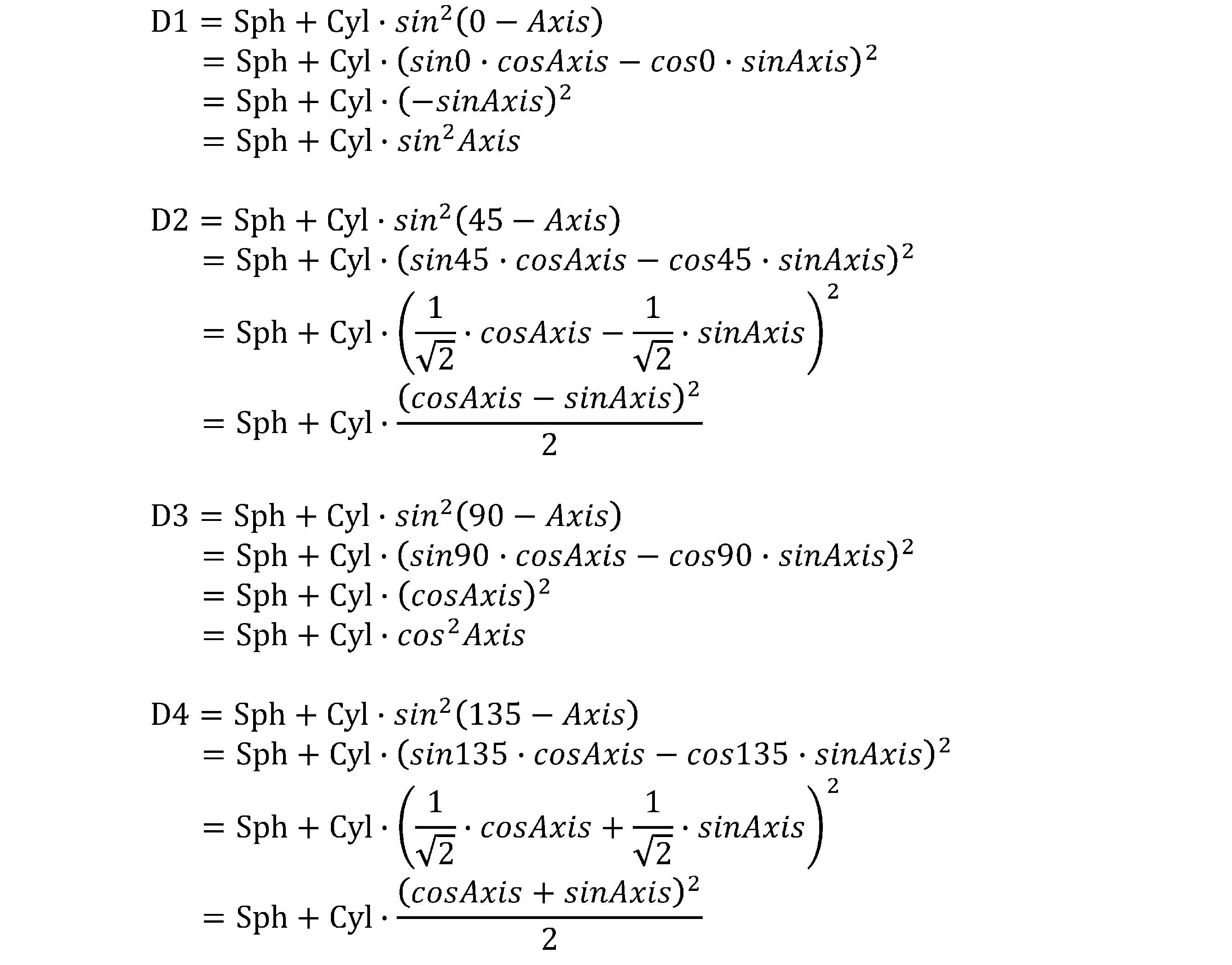
仮に、SNが2.00D、CNが-1.00D、乱視軸AxNが30度だった場合、D1Nは1.75D、D2Nは1.93D、D3Nは1.25D、D4Nは1.07Dとなる。
その場合、近用部に追加される度数D1~D4は、D1=D1N-D1F=1.75D、D2=D2N-D2F=2.43D、D3=D3N-D3F=2.25D、D4=D4N-D4F=1.57Dとなる。
そして、D1~D4を逆にS、C、Axへと変換する。その結果、球面度数Sβ1=2.50D、乱視度数Cβ1=-1.00Dおよび乱視軸Axβ1=60度となる。
・遠方視に要する遠用処方値を4方向断面度数D1F~D4Fに分解する。
・近方視に要する近用処方値を4方向断面度数D1N~D4Nに分解する。
・近方視4方向断面度数から遠方視4方向断面度数を差し引いたD1~D4を得る。
・D1~D4を逆にS、C、Axへと変換し、Sβ1、Cβ1、Axβ1を得る。
(2)乱視軸Axβ1から90度を減じて得られる乱視度数の増減方向T(但し0度未満の場合は180度を加えた値)が45~135度の範囲内の場合、Sβ1をSβに設定し、Cβ1をCβに設定し、Axβ1をAxβに設定する。
乱視度数ゼロDから乱視度数Cβに増加する分布の好適例は、測定点Fの位置において乱視度数ゼロDとし、測定点Nの位置において乱視度数Cβとした非点収差βの分布である。
非点収差βの付加の具体的な態様の一例として、EP3457195A1公報(以降、「参考公報」と称する。)に記載の内容が挙げられる。本明細書では、参考公報の内容を全て参照可能である。
本発明の一態様の累進屈折力レンズの構成は以下の通りである。「近方距離を見る近方視のための近用処方値を有する下方の近用部と、近方距離よりも遠くの距離を見る遠方視のための遠用処方値を有する上方の遠用部と、遠用部と近用部との間を繋ぐように度数が変化する中間部と、を備え、
遠用部において、遠方視に要する遠用処方値であるところの、球面度数SF、乱視度数CFおよび乱視軸AxFが設定され、且つ、近用部において、近方視に要する近用処方値であるところの、球面度数SN(=SF+加入度数ADD)、乱視度数CNおよび乱視軸AxNが設定され、
CNはCFとは異なる値、AxFはAxNとは異なる値、またはその両方であり、
遠用部、近用部および中間部に乱視度数が設定されていない基本累進面と、
遠用部、近用部および中間部に一様に付加される曲率分布であって、遠用部においてCFおよびAxFを実現する、大きさの異なる2つの主曲率の組α(k1α,k2α)の曲率分布と、
組αの曲率分布とは別の、大きさの異なる2つの主曲率の組β(k1β,k2β)の曲率分布であって、所定の方向に主曲率差の絶対値(|k1β-k2β|)が増加する曲率分布と、が合わさった状態で、遠用部においてCFおよびAxFが実現され且つ近用部においてCNおよびAxNが実現される、累進屈折力レンズ。」
「近方距離を見る近方視のための近用処方値を有する下方の近用部と、近方距離よりも遠くの距離を見る遠方視のための遠用処方値を有する上方の遠用部と、遠用部と近用部との間を繋ぐように度数が変化する中間部と、を備え、
遠用部において、遠方視に要する遠用処方値であるところの、球面度数SF、乱視度数CFおよび乱視軸AxFが設定され、且つ、近用部において、近方視に要する近用処方値であるところの、球面度数SN(=SF+加入度数ADD)、乱視度数CNおよび乱視軸AxNが設定され、
CNはCFとは異なる値、AxFはAxNとは異なる値、またはその両方であり、
遠用部、近用部および中間部に乱視度数が設定されていない基本累進面と、
遠用部においてCFおよびAxFを実現する非点収差であって、遠用部、近用部および中間部に一様に付加される非点収差αと、
非点収差αとは別の非点収差であって、所定の方向に非点収差が増加する分布を有する非点収差βと、が合わさった状態で、遠用部においてCFおよびAxFが実現され且つ近用部においてCNおよびAxNが実現される、累進屈折力レンズ。」
図5は、実施例1における累進屈折力レンズの設計方法の説明図である。
上側の分布は平均屈折力分布であり、下側の分布は非点収差分布である。最左側は基本累進面の各分布を示し、その右側は非点収差β(下)とそれに伴う平均屈折力分布(上)を示し、最右側は非点収差α付加工程および非点収差β付加工程を行った後の各分布を示す。
SF: 0.00D(ゼロD)
CF:-1.00D
AxF:180度
近用処方値を以下のように設定する。
SN: 2.00D(すなわちADD:2.00D)
CN:-1.00D
AxN:30度
Sβ1:2.50D
Cβ1:-1.00D
Axβ1:60度
図6(a)は、測定点Fにおいて非点収差がゼロD、測定点Nにおいて非点収差が1.00Dであり、鉛直上方から鉛直下方に向けて非点収差を増加させ、等高線を水平線とした分布である。
図6(b)は、乱視軸Axβを実現するよう光学中心OCを中心に図6(a)の分布を回転させた状態を示す図である。 図6(c)は、基本累進面の非点収差分布である。Sβ2とSβ1との間で差分を調整すべく、基本累進面でのADDは1.50Dに設定する。
図6(d)は、図6(c)に対する非点収差β付加工程後であって非点収差α付加工程前の非点収差分布である。
図6(e)は、図6(d)に対する非点収差α付加工程後の非点収差分布であり、図5の最右側の下図と同一である。
Sβ2:1.50D
Cβ2:1.00D
Sβ2をSβに設定し、Cβ2をCβに設定し、Axβ1をAxβに設定した。つまり、実施例1での非点収差βの分布では、60度方向の逆方向である-120度方向(右上側から左下側)に向けて屈折力および非点収差が増加する。
上側の分布は平均屈折力分布であり、下側の分布は非点収差分布である。最左側は実施例1において得られた累進屈折力レンズの各分布を示し、その右側は、実施例1において得られた累進屈折力レンズから遠用処方値を差し引いたときの各分布を示し、最右側は、実施例1において得られた累進屈折力レンズから近用処方値を差し引いたときの各分布を示す。
Claims (5)
- 近方距離を見る近方視のための近用処方値を有する下方の近用部と、近方距離よりも遠くの距離を見る遠方視のための遠用処方値を有する上方の遠用部と、遠用部と近用部との間を繋ぐように度数が変化する中間部と、を備え、
遠用部において、遠方視に要する遠用処方値であるところの、球面度数SF、乱視度数CFおよび乱視軸AxFが設定され、且つ、近用部において、近方視に要する近用処方値であるところの、球面度数SN(=SF+加入度数ADD)、乱視度数CNおよび乱視軸AxNが設定され、
CNはCFとは異なる値、AxFはAxNとは異なる値、またはその両方であり、
遠用部、近用部および中間部に乱視度数が設定されていない基本累進面と、
遠用部、近用部および中間部に一様に付加される曲率分布であって、遠用部においてCFおよびAxFを実現する、大きさの異なる2つの主曲率の組α(k1α,k2α)の曲率分布と、
組αの曲率分布とは別の、大きさの異なる2つの主曲率の組β(k1β,k2β)の曲率分布であって所定の方向に主曲率差の絶対値(|k1β-k2β|)が増加する曲率分布と、が合わさった状態で、遠用部においてCFおよびAxFが実現され且つ近用部においてCNおよびAxNが実現される、累進屈折力レンズ。 - 組βは、一つの乱視軸Axβを有し、球面度数ゼロDから球面度数Sβに増加し、且つ、乱視度数ゼロDから乱視度数Cβに増加する分布を有し、
Sβ、CβおよびAxβは、以下の手順により決定される、請求項1に記載の累進屈折力レンズ。
[手順1]
近用部の近用処方値から遠用部の遠用処方値をベクトル減算し、球面度数Sβ1、乱視度数Cβ1および乱視軸Axβ1を算出する。
[手順2](1)乱視軸Axβ1から90度を減じて得られる乱視度数の増減方向T(但し0度未満の場合は180度を加えた値)が45~135度の範囲外の場合、乱視軸Axβ1の値を乱視度数の増減方向Tの値に置き換えた状態へとSβ1およびCβ1を変換して変換後球面度数Sβ2および変換後乱視度数Cβ2を算出し、Sβ2をSβに設定し、Cβ2をCβに設定し、Axβ1をAxβに設定する。
(2)乱視軸Axβ1から90度を減じて得られる乱視度数の増減方向T(但し0度未満の場合は180度を加えた値)が45~135度の範囲内の場合、Sβ1をSβに設定し、Cβ1をCβに設定し、Axβ1をAxβに設定する。 - 近方距離を見る近方視のための近用処方値を有する下方の近用部と、近方距離よりも遠くの距離を見る遠方視のための遠用処方値を有する上方の遠用部と、遠用部と近用部との間を繋ぐように度数が変化する中間部と、を備え、
遠用部において遠方視に要する遠用処方値であるところの、球面度数SF、乱視度数CFおよび乱視軸AxFが設定され、且つ、近用部において近方視に要する近用処方値であるところの、球面度数SN(=SF+加入度数ADD)、乱視度数CNおよび乱視軸AxNが設定され、
CNはCFとは異なる値、AxFはAxNとは異なる値、またはその両方である累進屈折力レンズの設計方法であって、
遠用部においてCFおよびAxFを実現する、大きさの異なる2つの主曲率の組α(k1α,k2α)の曲率分布を、遠用部、近用部および中間部に一様に付加する組α付加工程と、
組αの曲率分布とは別の、大きさの異なる2つの主曲率の組β(k1β,k2β)の曲率分布であって、所定の方向に主曲率差の絶対値(|k1β-k2β|)が増加する曲率分布を付加する組β付加工程と、を有し、
組βは、遠用部、近用部および中間部に乱視度数が設定されていない基本累進面に対する組α付加工程および組β付加工程の後に、遠用部においてCFおよびAxFを実現可能な分布であり且つ近用部においてCNおよびAxNを実現可能な曲率分布を有する、累進屈折力レンズの設計方法。 - 組α付加工程および組β付加工程の前に、
乱視矯正用の度数を備える前の遠用部、近用部および中間部を有する基本累進面を準備する準備工程と、
近用部の近用処方値から遠用部の遠用処方値をベクトル減算し、球面度数Sβ1、乱視度数Cβ1および乱視軸Axβ1を算出する算出工程と、を有し、
乱視軸Axβ1から90度を減じて得られる乱視度数の増減方向T(但し0度未満の場合は180度を加えた値)が45~135度の範囲外の場合、乱視軸Axβ1の値を乱視度数の増減方向Tの値に置き換えた状態へとSβ1およびCβ1を変換する変換工程を行い、変換後球面度数Sβ2および変換後乱視度数Cβ2を算出し、Sβ2をSβに設定し、Cβ2をCβに設定し、Axβ1をAxβに設定し、
乱視軸Axβ1から90度を減じて得られる乱視度数の増減方向T(但し0度未満の場合は180度を加えた値)が45~135度の範囲内の場合、Sβ1をSβに設定し、Cβ1をCβに設定し、Axβ1をAxβに設定し、
一つの乱視軸Axβを有し、球面度数ゼロDから球面度数Sβに増加し、且つ、乱視度数ゼロDから乱視度数Cβに増加するような曲率分布を有する組βを得る組β取得工程を行った後、基本累進面に対し、組α付加工程および組β付加工程を行う、請求項3に記載の累進屈折力レンズの設計方法。 - 組β付加工程の後に、組α付加工程を行う、請求項3または4に記載の累進屈折力レンズの設計方法。
Priority Applications (2)
| Application Number | Priority Date | Filing Date | Title |
|---|---|---|---|
| EP21771771.9A EP4123363B1 (en) | 2020-03-19 | 2021-01-12 | Progressive refraction lens and design method therefor |
| US17/911,512 US12399385B2 (en) | 2020-03-19 | 2021-01-12 | Progressive power lens and designing method thereof |
Applications Claiming Priority (2)
| Application Number | Priority Date | Filing Date | Title |
|---|---|---|---|
| JP2020-049477 | 2020-03-19 | ||
| JP2020049477A JP7313304B2 (ja) | 2020-03-19 | 2020-03-19 | 累進屈折力レンズの設計方法 |
Publications (1)
| Publication Number | Publication Date |
|---|---|
| WO2021186861A1 true WO2021186861A1 (ja) | 2021-09-23 |
Family
ID=77770811
Family Applications (1)
| Application Number | Title | Priority Date | Filing Date |
|---|---|---|---|
| PCT/JP2021/000680 Ceased WO2021186861A1 (ja) | 2020-03-19 | 2021-01-12 | 累進屈折力レンズおよびその設計方法 |
Country Status (4)
| Country | Link |
|---|---|
| US (1) | US12399385B2 (ja) |
| EP (1) | EP4123363B1 (ja) |
| JP (1) | JP7313304B2 (ja) |
| WO (1) | WO2021186861A1 (ja) |
Citations (4)
| Publication number | Priority date | Publication date | Assignee | Title |
|---|---|---|---|---|
| JP2001021846A (ja) * | 1999-07-08 | 2001-01-26 | Sota Suzuki | 眼鏡用累進焦点レンズ及びその製造方法並びに眼鏡用累進焦点レンズを用いた眼鏡 |
| JP2005326294A (ja) | 2004-05-14 | 2005-11-24 | Pentax Corp | 光学特性の補間方法およびその方法を用いたレンズの評価装置 |
| JP2013525851A (ja) | 2010-04-28 | 2013-06-20 | ローデンストック.ゲゼルシャフト.ミット.ベシュレンクテル.ハフツング | 視野角に依存する処方データを用いて眼鏡レンズを計算する方法 |
| EP3457195A1 (en) | 2017-09-19 | 2019-03-20 | Hoya Lens Thailand Ltd. | Spectacle lenses and methods for producing the same |
Family Cites Families (3)
| Publication number | Priority date | Publication date | Assignee | Title |
|---|---|---|---|---|
| US6802607B2 (en) | 2002-10-31 | 2004-10-12 | Johnson & Johnson Vision Care, Inc. | Progressive cylinder ophthalmic lenses |
| FR2858693B1 (fr) | 2003-08-08 | 2005-10-28 | Essilor Int | Procede de determination d'une lentille ophtalmique utilisant une prescription d'astigmatisme en vision de loin et en vision de pres |
| WO2016056649A1 (ja) * | 2014-10-10 | 2016-04-14 | ホヤ レンズ タイランド リミテッド | 累進屈折力レンズ |
-
2020
- 2020-03-19 JP JP2020049477A patent/JP7313304B2/ja active Active
-
2021
- 2021-01-12 EP EP21771771.9A patent/EP4123363B1/en active Active
- 2021-01-12 WO PCT/JP2021/000680 patent/WO2021186861A1/ja not_active Ceased
- 2021-01-12 US US17/911,512 patent/US12399385B2/en active Active
Patent Citations (4)
| Publication number | Priority date | Publication date | Assignee | Title |
|---|---|---|---|---|
| JP2001021846A (ja) * | 1999-07-08 | 2001-01-26 | Sota Suzuki | 眼鏡用累進焦点レンズ及びその製造方法並びに眼鏡用累進焦点レンズを用いた眼鏡 |
| JP2005326294A (ja) | 2004-05-14 | 2005-11-24 | Pentax Corp | 光学特性の補間方法およびその方法を用いたレンズの評価装置 |
| JP2013525851A (ja) | 2010-04-28 | 2013-06-20 | ローデンストック.ゲゼルシャフト.ミット.ベシュレンクテル.ハフツング | 視野角に依存する処方データを用いて眼鏡レンズを計算する方法 |
| EP3457195A1 (en) | 2017-09-19 | 2019-03-20 | Hoya Lens Thailand Ltd. | Spectacle lenses and methods for producing the same |
Non-Patent Citations (1)
| Title |
|---|
| See also references of EP4123363A4 |
Also Published As
| Publication number | Publication date |
|---|---|
| EP4123363A1 (en) | 2023-01-25 |
| US20230114677A1 (en) | 2023-04-13 |
| JP7313304B2 (ja) | 2023-07-24 |
| EP4123363A4 (en) | 2024-04-10 |
| EP4123363B1 (en) | 2026-03-04 |
| JP2021148979A (ja) | 2021-09-27 |
| US12399385B2 (en) | 2025-08-26 |
Similar Documents
| Publication | Publication Date | Title |
|---|---|---|
| US9557578B2 (en) | Methods for determining a progressive ophthalmic lens | |
| JP4164550B2 (ja) | 累進屈折力眼鏡レンズ | |
| JPWO2009072528A1 (ja) | 一対の累進屈折力レンズ及びその設計方法 | |
| JP2009517709A (ja) | 眼鏡レンズ | |
| WO2005066696A1 (ja) | 両面非球面型累進屈折力レンズおよびその設計方法 | |
| JP3617004B2 (ja) | 両面非球面型累進屈折力レンズ | |
| EP2780758A1 (en) | A method for determining an ophthalmic lens | |
| JP4618656B2 (ja) | 累進多焦点レンズシリーズ | |
| EP2684094A1 (en) | A method for determining a progressive ophthalmic lens | |
| JP5388579B2 (ja) | 眼鏡レンズ | |
| KR101281459B1 (ko) | 안과용 렌즈를 결정하는 방법 | |
| JP4380887B2 (ja) | 累進多焦点レンズ | |
| CN107077008B (zh) | 用于修改眼科镜片表面的屈光功能的方法 | |
| CN107111158A (zh) | 眼镜镜片、其制造方法、供给系统及供给程序 | |
| WO2013046677A1 (ja) | 累進屈折力レンズ | |
| US20130148078A1 (en) | Progressive multifocal ophthalmic lens | |
| JP6294466B2 (ja) | 累進屈折力レンズの設計方法および製造方法、ならびに累進屈折力レンズ製造システム | |
| WO2021186861A1 (ja) | 累進屈折力レンズおよびその設計方法 | |
| JP4219148B2 (ja) | 両面非球面型累進屈折力レンズ | |
| US11681163B2 (en) | Pair of progressive power lenses and design method for the same | |
| WO2024126255A1 (en) | Optical design and spectral transmission optimization | |
| JP4219352B2 (ja) | 両面非球面型累進屈折力レンズ | |
| CN106605168A (zh) | 眼镜眼科镜片、用于确定眼镜眼科镜片的方法 | |
| WO2010044260A1 (ja) | 累進屈折力レンズ | |
| WO2010044266A1 (ja) | 累進屈折力レンズ及び累進屈折力レンズシリーズ |
Legal Events
| Date | Code | Title | Description |
|---|---|---|---|
| 121 | Ep: the epo has been informed by wipo that ep was designated in this application |
Ref document number: 21771771 Country of ref document: EP Kind code of ref document: A1 |
|
| NENP | Non-entry into the national phase |
Ref country code: DE |
|
| ENP | Entry into the national phase |
Ref document number: 2021771771 Country of ref document: EP Effective date: 20221019 |
|
| WWG | Wipo information: grant in national office |
Ref document number: 17911512 Country of ref document: US |
|
| WWG | Wipo information: grant in national office |
Ref document number: 2021771771 Country of ref document: EP |