WO2021187408A1 - 電縫鋼管、その製造方法および自動車用構造部材 - Google Patents
電縫鋼管、その製造方法および自動車用構造部材 Download PDFInfo
- Publication number
- WO2021187408A1 WO2021187408A1 PCT/JP2021/010334 JP2021010334W WO2021187408A1 WO 2021187408 A1 WO2021187408 A1 WO 2021187408A1 JP 2021010334 W JP2021010334 W JP 2021010334W WO 2021187408 A1 WO2021187408 A1 WO 2021187408A1
- Authority
- WO
- WIPO (PCT)
- Prior art keywords
- pipe
- ave
- steel pipe
- region
- seam
- Prior art date
- Legal status (The legal status is an assumption and is not a legal conclusion. Google has not performed a legal analysis and makes no representation as to the accuracy of the status listed.)
- Ceased
Links
Images


Classifications
-
- F—MECHANICAL ENGINEERING; LIGHTING; HEATING; WEAPONS; BLASTING
- F16—ENGINEERING ELEMENTS AND UNITS; GENERAL MEASURES FOR PRODUCING AND MAINTAINING EFFECTIVE FUNCTIONING OF MACHINES OR INSTALLATIONS; THERMAL INSULATION IN GENERAL
- F16L—PIPES; JOINTS OR FITTINGS FOR PIPES; SUPPORTS FOR PIPES, CABLES OR PROTECTIVE TUBING; MEANS FOR THERMAL INSULATION IN GENERAL
- F16L9/00—Rigid pipes
- F16L9/17—Rigid pipes obtained by bending a sheet longitudinally and connecting the edges
-
- B—PERFORMING OPERATIONS; TRANSPORTING
- B21—MECHANICAL METAL-WORKING WITHOUT ESSENTIALLY REMOVING MATERIAL; PUNCHING METAL
- B21B—ROLLING OF METAL
- B21B17/00—Tube-rolling by rollers of which the axes are arranged essentially perpendicular to the axis of the work, e.g. "axial" tube-rolling
- B21B17/14—Tube-rolling by rollers of which the axes are arranged essentially perpendicular to the axis of the work, e.g. "axial" tube-rolling without mandrel, e.g. stretch-reducing mills
-
- B—PERFORMING OPERATIONS; TRANSPORTING
- B21—MECHANICAL METAL-WORKING WITHOUT ESSENTIALLY REMOVING MATERIAL; PUNCHING METAL
- B21C—MANUFACTURE OF METAL SHEETS, WIRE, RODS, TUBES, PROFILES OR LIKE SEMI-MANUFACTURED PRODUCTS OTHERWISE THAN BY ROLLING; AUXILIARY OPERATIONS USED IN CONNECTION WITH METAL-WORKING WITHOUT ESSENTIALLY REMOVING MATERIAL
- B21C37/00—Manufacture of metal sheets, rods, wire, tubes, profiles or like semi-manufactured products, not otherwise provided for; Manufacture of tubes of special shape
- B21C37/06—Manufacture of metal sheets, rods, wire, tubes, profiles or like semi-manufactured products, not otherwise provided for; Manufacture of tubes of special shape of tubes or metal hoses; Combined procedures for making tubes, e.g. for making multi-wall tubes
- B21C37/08—Making tubes with welded or soldered seams
- B21C37/0807—Tube treating or manipulating combined with, or specially adapted for use in connection with tube making machines, e.g. drawing-off devices, cutting-off
-
- B—PERFORMING OPERATIONS; TRANSPORTING
- B21—MECHANICAL METAL-WORKING WITHOUT ESSENTIALLY REMOVING MATERIAL; PUNCHING METAL
- B21C—MANUFACTURE OF METAL SHEETS, WIRE, RODS, TUBES, PROFILES OR LIKE SEMI-MANUFACTURED PRODUCTS OTHERWISE THAN BY ROLLING; AUXILIARY OPERATIONS USED IN CONNECTION WITH METAL-WORKING WITHOUT ESSENTIALLY REMOVING MATERIAL
- B21C37/00—Manufacture of metal sheets, rods, wire, tubes, profiles or like semi-manufactured products, not otherwise provided for; Manufacture of tubes of special shape
- B21C37/06—Manufacture of metal sheets, rods, wire, tubes, profiles or like semi-manufactured products, not otherwise provided for; Manufacture of tubes of special shape of tubes or metal hoses; Combined procedures for making tubes, e.g. for making multi-wall tubes
- B21C37/30—Finishing tubes, e.g. sizing, burnishing
-
- B—PERFORMING OPERATIONS; TRANSPORTING
- B21—MECHANICAL METAL-WORKING WITHOUT ESSENTIALLY REMOVING MATERIAL; PUNCHING METAL
- B21D—WORKING OR PROCESSING OF SHEET METAL OR METAL TUBES, RODS OR PROFILES WITHOUT ESSENTIALLY REMOVING MATERIAL; PUNCHING METAL
- B21D5/00—Bending sheet metal along straight lines, e.g. to form simple curves
- B21D5/06—Bending sheet metal along straight lines, e.g. to form simple curves by drawing procedure making use of dies or forming-rollers, e.g. making profiles
- B21D5/10—Bending sheet metal along straight lines, e.g. to form simple curves by drawing procedure making use of dies or forming-rollers, e.g. making profiles for making tubes
- B21D5/12—Bending sheet metal along straight lines, e.g. to form simple curves by drawing procedure making use of dies or forming-rollers, e.g. making profiles for making tubes making use of forming-rollers
-
- C—CHEMISTRY; METALLURGY
- C21—METALLURGY OF IRON
- C21D—MODIFYING THE PHYSICAL STRUCTURE OF FERROUS METALS; GENERAL DEVICES FOR HEAT TREATMENT OF FERROUS OR NON-FERROUS METALS OR ALLOYS; MAKING METAL MALLEABLE, e.g. BY DECARBURISATION OR TEMPERING
- C21D1/00—General methods or devices for heat treatment, e.g. annealing, hardening, quenching or tempering
- C21D1/18—Hardening; Quenching with or without subsequent tempering
- C21D1/25—Hardening, combined with annealing between 300 degrees Celsius and 600 degrees Celsius, i.e. heat refining ("Vergüten")
-
- C—CHEMISTRY; METALLURGY
- C21—METALLURGY OF IRON
- C21D—MODIFYING THE PHYSICAL STRUCTURE OF FERROUS METALS; GENERAL DEVICES FOR HEAT TREATMENT OF FERROUS OR NON-FERROUS METALS OR ALLOYS; MAKING METAL MALLEABLE, e.g. BY DECARBURISATION OR TEMPERING
- C21D1/00—General methods or devices for heat treatment, e.g. annealing, hardening, quenching or tempering
- C21D1/26—Methods of annealing
-
- C—CHEMISTRY; METALLURGY
- C21—METALLURGY OF IRON
- C21D—MODIFYING THE PHYSICAL STRUCTURE OF FERROUS METALS; GENERAL DEVICES FOR HEAT TREATMENT OF FERROUS OR NON-FERROUS METALS OR ALLOYS; MAKING METAL MALLEABLE, e.g. BY DECARBURISATION OR TEMPERING
- C21D7/00—Modifying the physical properties of iron or steel by deformation
- C21D7/13—Modifying the physical properties of iron or steel by deformation by hot working
-
- C—CHEMISTRY; METALLURGY
- C21—METALLURGY OF IRON
- C21D—MODIFYING THE PHYSICAL STRUCTURE OF FERROUS METALS; GENERAL DEVICES FOR HEAT TREATMENT OF FERROUS OR NON-FERROUS METALS OR ALLOYS; MAKING METAL MALLEABLE, e.g. BY DECARBURISATION OR TEMPERING
- C21D8/00—Modifying the physical properties of ferrous metals or ferrous alloys by deformation combined with, or followed by, heat treatment
- C21D8/10—Modifying the physical properties of ferrous metals or ferrous alloys by deformation combined with, or followed by, heat treatment during manufacturing of tubular bodies
-
- C—CHEMISTRY; METALLURGY
- C21—METALLURGY OF IRON
- C21D—MODIFYING THE PHYSICAL STRUCTURE OF FERROUS METALS; GENERAL DEVICES FOR HEAT TREATMENT OF FERROUS OR NON-FERROUS METALS OR ALLOYS; MAKING METAL MALLEABLE, e.g. BY DECARBURISATION OR TEMPERING
- C21D9/00—Heat treatment, e.g. annealing, hardening, quenching or tempering, adapted for particular articles; Furnaces therefor
- C21D9/08—Heat treatment, e.g. annealing, hardening, quenching or tempering, adapted for particular articles; Furnaces therefor for tubular bodies or pipes
-
- C—CHEMISTRY; METALLURGY
- C21—METALLURGY OF IRON
- C21D—MODIFYING THE PHYSICAL STRUCTURE OF FERROUS METALS; GENERAL DEVICES FOR HEAT TREATMENT OF FERROUS OR NON-FERROUS METALS OR ALLOYS; MAKING METAL MALLEABLE, e.g. BY DECARBURISATION OR TEMPERING
- C21D9/00—Heat treatment, e.g. annealing, hardening, quenching or tempering, adapted for particular articles; Furnaces therefor
- C21D9/50—Heat treatment, e.g. annealing, hardening, quenching or tempering, adapted for particular articles; Furnaces therefor for welded joints
-
- B—PERFORMING OPERATIONS; TRANSPORTING
- B21—MECHANICAL METAL-WORKING WITHOUT ESSENTIALLY REMOVING MATERIAL; PUNCHING METAL
- B21B—ROLLING OF METAL
- B21B2261/00—Product parameters
- B21B2261/02—Transverse dimensions
- B21B2261/04—Thickness, gauge
-
- B—PERFORMING OPERATIONS; TRANSPORTING
- B21—MECHANICAL METAL-WORKING WITHOUT ESSENTIALLY REMOVING MATERIAL; PUNCHING METAL
- B21B—ROLLING OF METAL
- B21B2261/00—Product parameters
- B21B2261/02—Transverse dimensions
- B21B2261/10—Cross-sectional area
-
- B—PERFORMING OPERATIONS; TRANSPORTING
- B21—MECHANICAL METAL-WORKING WITHOUT ESSENTIALLY REMOVING MATERIAL; PUNCHING METAL
- B21B—ROLLING OF METAL
- B21B2265/00—Forming parameters
- B21B2265/14—Reduction rate
-
- B—PERFORMING OPERATIONS; TRANSPORTING
- B21—MECHANICAL METAL-WORKING WITHOUT ESSENTIALLY REMOVING MATERIAL; PUNCHING METAL
- B21B—ROLLING OF METAL
- B21B27/00—Rolls, roll alloys or roll fabrication; Lubricating, cooling or heating rolls while in use
- B21B27/02—Shape or construction of rolls
- B21B27/024—Rolls for bars, rods, rounds, tubes, wire or the like
Definitions
- the present invention relates to an electric resistance welded steel pipe technique that is suitable for an automobile stabilizer and has excellent torsional fatigue resistance.
- the stabilizer which has conventionally used a steel bar, has been hollowed out by applying an electrosewn steel pipe having excellent productivity. Since these automobile parts such as stabilizers are bent, high workability is required, and bending and torsional stress continue to act during use as a product, resulting in excellent fatigue characteristics (hereinafter referred to as torsion resistance). Fatigue characteristics) are also required.
- Patent Document 1 in order to satisfy the required torsional fatigue resistance, a region called a white layer is specified in which the carbon content is reduced in the electrosewn welded portion and the hardness after quenching is lower than the surroundings.
- Welded steel pipes have been proposed.
- Patent Document 2 proposes an electrosewn steel pipe having improved torsional fatigue resistance by defining a welding defect area and limiting the area.
- An object of the present invention is to provide a technique for an electrosewn steel pipe having excellent workability and torsional fatigue resistance in order to solve the above problems.
- the present inventors have conducted research on torsional fatigue of steel pipes, and found that the shape of the inner diameter of the steel pipe near the electric stitch welded joint changes after rolling at a reduced diameter, and this shape change affects the torsional fatigue characteristics. I found out. Then, in order to achieve the above object, the present inventors have diligently studied various measures for improving the inner diameter shape in the vicinity of the electric stitch welding seam in the method of hot-reducing diameter rolling of a steel pipe. As a result, it was found that the inner diameter shape near the electric stitch welding seam changes depending on the position of the rolling roll in the reduced diameter rolling process and the electric sewing welding seam of the steel pipe during the reduced diameter rolling. Then, they have found that the inner diameter shape is improved by optimizing the charging position of the steel pipe into the rolling roll during the reduced diameter rolling process, and both high workability and improved fatigue characteristics can be realized.
- the gist of the present invention is as follows.
- An electric resistance steel pipe composed of a seam region formed in the longitudinal direction of the pipe and a region up to ⁇ 10 ° in the circumferential direction of the pipe and a base material region other than the seam region.
- the r value in the longitudinal direction of the pipe is 1.0 or more, H (mm) which is the difference (Tb (Ave) -Ts (MIN) ) between the minimum wall thickness Ts (MIN) (mm) of the seam region and the average wall thickness Tb (Ave) (mm) of the base material region.
- H (mm) which is the difference (Tb (Ave) -Ts (MIN) ) between the minimum wall thickness Ts (MIN) (mm) of the seam region and the average wall thickness Tb (Ave) (mm) of the base material region.
- the arc length W (mm) of the inner surface of the pipe in the seam region satisfy the following equation (1).
- a technique for an electrosewn steel pipe having excellent workability and torsional fatigue resistance is provided.
- the electrosewn steel pipe according to the present invention is suitable as a structural member for automobiles such as a stabilizer which is bent and requires torsional fatigue resistance after cross-section molding.
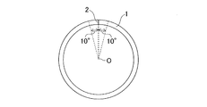
- FIG. 1 is a plan view showing a cross section of an electric resistance welded steel pipe.
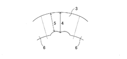
- FIG. 2 is a plan view of the seam region.
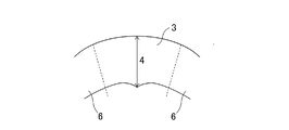
- FIG. 3 is a plan view of the seam region when the maximum wall thickness Ts (MAX) of the seam region becomes larger than the average wall thickness Tb (Ave) of the base material region.
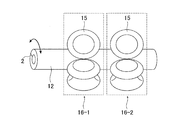
- FIG. 4 is an external view of the electric resistance welded steel pipe manufacturing equipment of the present invention.
- FIG. 5 is an external view for explaining the position of the electric resistance welded seam when the electric resistance pipe is charged into the rolling roll.
- FIG. 6 is an external view for explaining a portion of the rolling roll in which the electric stitch welding seam portion should avoid contact.
- FIG. 7 is a plan view of the rolling roll for explaining the phase angle of the rolling roll.
- FIG. 8 is a diagram showing the relationship between the charging position of the electric stitch welding seam portion with respect to the rolling roll in the embodiment and the region where contact should be avoided.
- the steel pipe of the present invention is an electro-sewn steel pipe composed of a seam region formed in the longitudinal direction of the pipe and a region up to ⁇ 10 ° in the circumferential direction of the pipe and a base material region other than the seam region. Therefore, the r value in the longitudinal direction of the pipe is 1.0 or more, and the difference between the minimum wall thickness Ts (MIN) (mm) in the seam region and the average wall thickness Tb (Ave) (mm) in the base metal region ( H (mm), which is Tb (Ave) -Ts (MIN) ), and the arc length W (mm) of the inner surface of the pipe in the seam region satisfy the following equation (1), and the maximum wall thickness Ts in the seam region.
- Ts (MAX) (mm) and Tb (Ave) (mm) are welded steel pipes having excellent torsional fatigue resistance, characterized in that they satisfy the following formula (2).
- H / W 0.10 ⁇ ⁇ ⁇ Equation (1)
- Ts (MAX) / Tb (Ave) ⁇ 1.05 ⁇ ⁇ ⁇ Equation (2)
- FIG. 1 shows the cross-sectional shape of the electric resistance welded steel pipe 1
- FIG. 2 shows an enlarged view of the seam region 3.
- the seam region 3 refers to a region from the electric stitch welding seam 2 to ⁇ 10 ° in the pipe circumferential direction when the center of the vertical cross section in the pipe axis direction (longitudinal direction) is the circular center ⁇ .
- the average wall thickness Tb (Ave) of the base metal region 6 is 40 °, 80 °, 120 °, 160 °, 200 when a single-ball micrometer is used and the joint portion of the electric stitch welding is set to 0 °.
- the wall thickness of the base metal region 6 at the positions of °, 240 °, 280 °, and 320 ° is measured, and the average value of the values is defined as Tb (Ave) (mm).
- Ts (MIN) (mm) and Ts (MAX) (mm) are the minimum wall thickness of the seam region 3 (the minimum wall thickness is obtained at the position indicated by reference numeral 5 in FIG. 2) and the seam region 3 respectively. It is defined by the maximum value of the wall thickness (the maximum value of the wall thickness is obtained at the position indicated by reference numeral 4 in FIG. 2).
- Ts (MIN) (mm) and Ts (MAX) (mm) the wall thickness of the section of the seam region 3 is measured with a point micrometer in 1 ° increments, and the minimum and maximum values are used.
- the electric resistance welded steel pipe of the present invention is not particularly limited, but the average wall thickness Tb (Ave) of the base metal region 6 is preferably 4.0 to 8.0 mm.
- the electric resistance welded steel pipe of the present invention is not particularly limited, but the average value Db (Ave) of the outer diameter of the pipe is preferably 20.0 to 45.0 mm.
- the r value can be the r value in the longitudinal direction of the pipe in the base metal region 6.
- the r value of the steel pipe 1 in the pipe longitudinal direction is set to 1.0 or more.
- the r value is 1.3 or more.
- the upper limit of the r value is not particularly limited, but if the r value is too high, deformation is concentrated in the circumferential direction of the pipe, and when the steel pipe 1 is bent, the diameter of the steel pipe cross section is reduced and a constriction occurs. It is preferably 2.0 or less because the desired shape may not be obtained.
- a tensile test piece of JIS No. 12A is taken from the base material region of the steel pipe, and a strain gauge having a gauge length of 2 mm is attached to the test.
- the r value can be adjusted by controlling the heating temperature during diameter reduction rolling and the cumulative diameter reduction ratio.
- Tb (Ave) -Ts (MIN) Tb (Ave) -Ts (MIN) .
- the arc length W (mm) of the seam region 3 shall be 0.10 or less.
- the H / W is preferably 0.07 or less, and more preferably 0.05 or less.
- the H / W is preferably ⁇ 0.10 or higher, and more preferably ⁇ 0.07 or higher.
- the H / W is such that the electric stitch welding seam portion 2 avoids a region within a specific range from the caliber end of the roll and the caliber center in a roll stand that reduces the diameter of one stand to a specific value or more. It can be adjusted to the above range by charging the raw pipe 12 into the pipe.
- FIG. 3 is a plan view of the seam region 3 when the maximum wall thickness Ts (MAX) of the seam region 3 becomes larger than the average wall thickness Tb (Ave) of the base material region 6. As shown in FIG.
- Ts (MAX) see reference numeral 4 in FIG. 3
- Tb (Ave) a problem may occur during the cold drawing process performed after diameter reduction rolling.
- the cold drawing process is a process of inserting a plug into a steel pipe and coldly pulling out the steel pipe through a die.
- Ts (MAX) / Tb (Ave) which is an index of thickening of the seam region 3, to 1.05 or less
- the ratio (Ts (MAX) / Tb (Ave) ) of the maximum wall thickness Ts (MAX) (mm) to Tb (ave) (mm) in the seam region is set to 1.05 or less.
- Ts (MAX) / Tb (Ave) is preferably 1.04 or less, and more preferably 1.03 or less.
- Ts (MAX) / Tb (Ave) is preferably 0.90 or more, and more preferably 0.95 or more.
- Ts (MAX) / Tb (Ave) in a roll stand that reduces the diameter per stand so that the diameter reduction ratio is equal to or greater than a specific value, avoid the area within a specific range from the caliber end and caliber center of the roll. It is possible to adjust to the above range by charging the electric stitch welding seam portion 2 at a suitable position.
- the ratio of T b (Ave) (mm) to the average value of the outer diameter of the pipe in the base metal region Db (ave) (mm): (Tb (Ave) / Db (Ave) ) ⁇ 100 Is preferably 15% or more.
- the reasons for limiting Tb (Ave) / Db (Ave) are as follows.
- the size of the steel pipe is preferably (Tb (Ave) / Db (Ave) ) ⁇ 100 ⁇ 15%. Further, preferably, (Tb (Ave) / Db (Ave) ) ⁇ 100 is 15.5% or more, and more preferably 16.0% or more. Further, preferably, (Tb (Ave) / Db (Ave) ) ⁇ 100 is 45% or less, and more preferably 40% or less.
- C 0.55% or less C is an element that contributes to the increase in strength, and its addition improves fatigue resistance, but if the C content exceeds 0.55%, weldability deteriorates, so it is stable. The quality of electric sewing welding may not be obtained. Therefore, the C content is preferably 0.55% or less. More preferably, the C content is 0.45% or less. Further, preferably, the C content is 0.2% or more.
- Si 0.01-1.0% Si deoxidizes and dissolves to increase the strength of steel.
- the Si content is preferably 0.01% or more. Further, if the Si content exceeds 1.0%, the hardenability of the steel pipe may decrease. Therefore, the Si content is preferably 0.01 to 1.0%. More preferably, the Si content is 0.1% or more. Further, more preferably, the Si content is 0.4% or less.
- Mn 0.2-3.0% Mn has an effect of improving hardenability, and the effect is obtained when it is contained in an amount of 0.2% or more. However, if the Mn content exceeds 3.0%, the electric sewing welding quality may deteriorate. Therefore, the Mn content is preferably 0.2 to 3.0%. More preferably, the Mn content is 0.5% or more. Further, more preferably, the Mn content is 2.0% or less.
- P 0.01% or less P segregates at grain boundaries and lowers toughness. Therefore, it is desirable to reduce P as much as possible in the present invention, but the P content can be up to 0.01%. Therefore, the P content is preferably 0.01% or less. More preferably, the P content is 0.005% or less.
- S 0.01% or less S is an element that exists as a sulfide inclusion in steel and lowers workability and fatigue resistance. Therefore, it is desirable to reduce S as much as possible in the present invention, but the S content is high. Up to 0.01% is acceptable. Therefore, the S content is preferably 0.01% or less. More preferably, the S content is 0.005% or less.
- Cr 2.0% or less Cr is an element that improves hardenability, is effective in increasing the strength of steel and improving fatigue characteristics. However, if Cr is contained in an amount of more than 2.0%, Cr oxide may remain in the joint portion of the electric stitch welding portion, and the electric sewing welding quality may deteriorate. Therefore, the Cr content is preferably 2.0% or less. More preferably, the Cr content is 0.5% or less. Further, the Cr content is preferably 0.001% or more.
- Ti 0.1% or less Ti has an action of fixing N in steel as TiN. However, if the Ti content exceeds 0.1%, the workability and toughness of the steel may decrease. Therefore, the Ti content is preferably 0.1% or less. More preferably, the Ti content is 0.04% or less. Moreover, the Ti content is preferably 0.01% or more.
- Al 0.1% or less
- Al is an element effective for deoxidation, and is an element necessary for ensuring the strength after quenching by suppressing the growth of austenite grains during quenching.
- the Al content is preferably 0.1% or less. More preferably, the Al content is 0.08% or less. Further, the Al content is preferably 0.01% or more.
- V 0.5% or less
- V is an element that forms fine carbides and contributes to the increase in steel strength.
- the V content is preferably 0.5% or less. More preferably, the V content is 0.3% or less. Further, preferably, the V content is 0.01% or more.
- Nb 0.1% or less Nb is an element that forms fine carbides and contributes to the increase in steel strength. However, if the Nb content exceeds 0.1%, the effect is saturated, and an effect commensurate with the content cannot be expected, which is economically disadvantageous. Therefore, the Nb content is preferably 0.1% or less. More preferably, the Nb content is 0.03% or less. Further, preferably, the Nb content is 0.001% or more.
- Mo 1.0% or less Mo is an element that improves hardenability and contributes to an increase in the strength of steel. However, if the Mo content exceeds 1.0%, the effect is saturated, and an effect commensurate with the content cannot be expected, which is economically disadvantageous. Therefore, the Mo content is preferably 1.0% or less. More preferably The Mo content is 0.3% or less. Further, preferably, the Mo content is 0.01% or more.
- Cu 2.0% or less
- Cu is an element that enhances hardenability and is effective in increasing the strength of steel and improving fatigue strength. However, if Cu is contained in excess of 2.0%, the workability may decrease. Therefore, the Cu content is preferably 2.0% or less. More preferably, the Cu content is 0.5% or less. Further, the Cu content is preferably 0.001% or more.
- Ni 2.0% or less
- Ni is an element that enhances hardenability and is effective in increasing the strength of steel and improving fatigue strength. However, if Ni is contained in excess of 2.0%, the workability may decrease. Therefore, the Ni content is preferably 2.0% or less. More preferably, the Ni content is 0.5% or less. Further, preferably, the Ni content is 0.001% or more.
- B 0.005% or less
- B is an element that enhances the hardenability of steel in a small amount.
- the B content is preferably 0.005% or less. More preferably, the B content is 0.0050% or less. Further, preferably, the B content is 0.0003% or more.
- N 0.01% or less N is an element that is inevitably contained in steel, but it combines with the nitride-forming element in steel to suppress coarsening of crystal grains and increase strength after tempering. Contribute. However, if the N content exceeds 0.01%, the toughness of the electric stitch welded seam is lowered and the workability is deteriorated. Therefore, the N content is preferably 0.01% or less. More preferably, the N content is 0.005% or less.
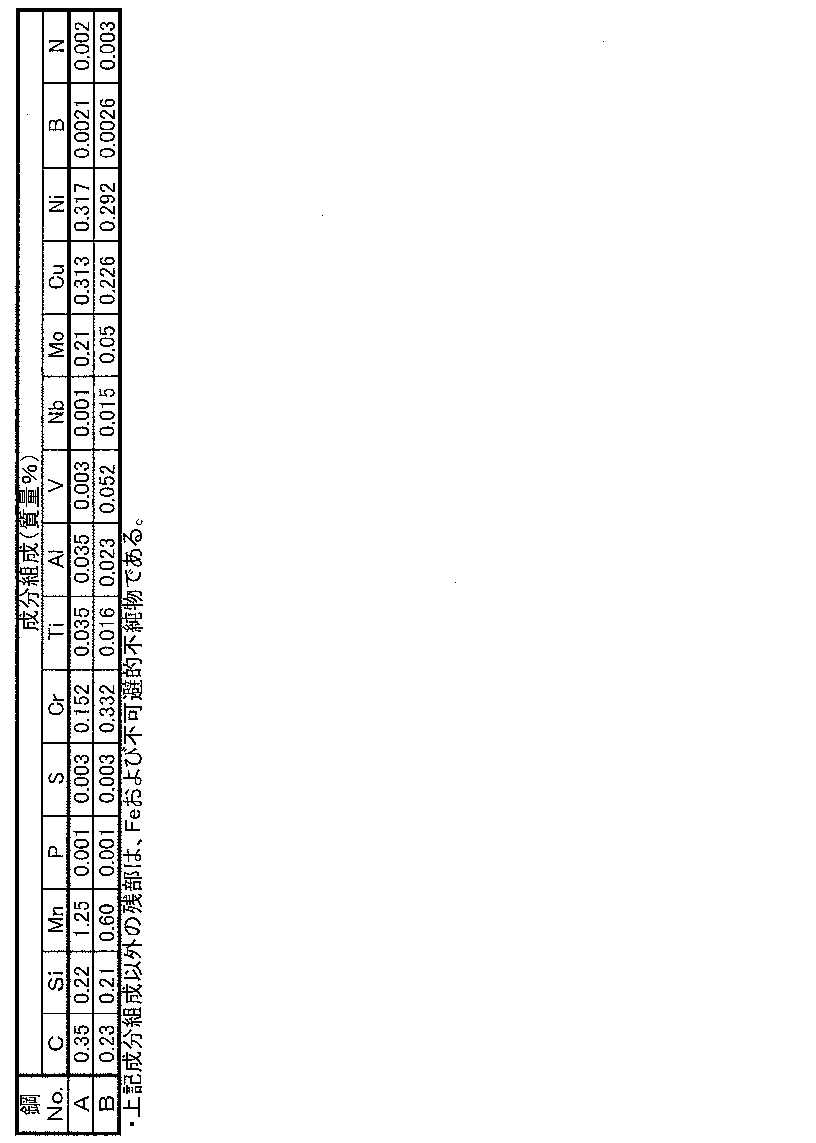
- the rest other than the above-mentioned component composition consists of Fe and unavoidable impurities.
- FIG. 4 shows a schematic view of equipment for manufacturing the electric resistance welded steel pipe of the present invention.
- the steel strip 7 is continuously formed by a continuous forming machine 8 or the like to form an open pipe 9, and the open pipe is electrically sewn by a welding means 10. Welding is performed to obtain a bare pipe 12.
- the circumferential butt portion of the steel strip 7 may be electrically resistance welded by the welding means 10 while being pressure-welded with the squeeze roll 11 to obtain the raw pipe 12. Further, the raw pipe 12 may be cut to a predetermined size by the cutting machine 13.
- the raw tube (tube body) 12 is heated by the heating means 14 at a heating temperature of 650 ° C. or higher, and a rolling roll (hereinafter, simply a roll) is heated. Also referred to as.) 15 is used to perform diameter reduction rolling at a cumulative diameter reduction ratio of 30% or more.
- a plurality of roll stands 16-1, 16-2 ..., 16-N (N is a natural number) can be used to gradually reduce the diameter.
- the diameter reduction ratio is defined by the following equation (5).
- Diameter reduction rate (%) 100 ⁇ (Db (Ave) before diameter reduction-Db (Ave) after diameter reduction) / Db (Ave) before diameter reduction ... Equation (5)
- the cumulative diameter reduction ratio is obtained by the following equation (6).
- Cumulative radial contraction rate (%) 100 ⁇ (the contraction diameter front of the first stand Db (Ave) - shrinkage ⁇ in the final stand Db (Ave)) / first reduced diameter front of stand Db ( Ave) ⁇ ⁇ ⁇ Equation (6)
- the heating temperature is preferably 700 ° C. or higher, more preferably 800 ° C. or higher.
- the heating temperature is preferably 1050 ° C. or lower, more preferably 1000 ° C. or lower.
- the cumulative diameter reduction ratio is preferably 35% or more, more preferably 40% or more.
- the cumulative diameter reduction ratio is preferably 90% or less, more preferably 85% or less.
- the range is ⁇ 5.0 ° from the center of the caliber of the roll and 360 ° / (n ⁇ 2) from the center of the caliber to the left and right, respectively. ) Is within ⁇ 5.0 ° (n is the number of rolls per stand) so that the electric stitch welding seam 2 is not passed.
- the diameter reduction ratio of the Nth stand in the roll stand referred to here can be obtained by the following formula (7).
- Radial contraction rate (%) 100 ⁇ (the contraction diameter front at the N stands Db (Ave) - Db shrinkage ⁇ at the N stand (Ave)) / N-th of reduced diameter front of stand Db ( Ave) ⁇ ⁇ ⁇ Equation (7)
- the charging position of the electric stitch welding seam portion 2 is the direction in which the steel pipe advances when charging into the roll for diameter reduction rolling, and electric sewing is performed counterclockwise from the ceiling direction with the center of the steel pipe as the axis. This is the circumferential position when the weld seam is rotated. At this time, the ceiling direction is set to 0 °. Further, the position of 360 ° / (n ⁇ 2) from the center of the caliber to the left and right can be said to be a position of ⁇ 360 ° / (n ⁇ 2) from the center of the caliber.
- FIG. 5 is a diagram for explaining the charging position of the electrosewn steel pipe.
- FIG. 6 is an external view for explaining a position where the electric stitch welding seam portion 2 should avoid contact with the rolling roll 15 in the present invention.
- the roll 15 for reducing the diameter of the steel pipe has a caliber formed in the circumferential direction of the roll, and the steel pipe (bare pipe 12) is sandwiched by the caliber while the plurality of rolls 15 rotate.
- the caliber In the vertical cross section (longitudinal direction) of the steel pipe (longitudinal direction), the caliber has a curved shape along the outer diameter of the steel pipe in the vertical cross section in the pipe axis direction.
- the caliber center 17 at the position of the arc where the caliber diameter 18 about the rotation axis of the roll is the minimum becomes the caliber bottom.
- the present inventors set the electric stitch welding joint 2 at various positions in the circumferential direction, and charged the raw pipe 12 into the roll 15 (16-1) for diameter reduction rolling. ..
- the range of ⁇ 5.0 ° from the caliber center 17 of the roll 15 and the caliber center 17 The raw pipe 12 is charged so that the electric stitch welding seam 2 avoids the range of ⁇ 5.0 ° (n is the number of rolls per stand) from the position of 360 ° / (n ⁇ 2) to the left and right respectively.
- n is the number of rolls per stand
- ⁇ 5.0 ° from the center of the caliber means that the outer edge of the caliber in the vertical cross section of the roll 15 in the pipe axis direction has a fan shape along the cross section circle of the steel tube, that is, the center of the cross section circle of the steel tube.
- the center of the caliber 17 is 0 °, which means that the fan shape is in the range of ⁇ 5.0 °.
- the roll 15 adjacent to the pipe circumferential direction is ⁇ 5.0 ° from the position of 360 ° / (n ⁇ 2) from the caliber center 17 on the right end side of the left roll 15.
- the region and the region ⁇ 5.0 ° from the position of 360 ° / (n ⁇ 2) from the caliber center 17 on the left end side of the roll 15 on the right side may overlap.
- roll-type guides are adjacent to each other.
- a method of installing between the stands 16 and using this guide to restrain the circumferential displacement of the pipe passing between the stands 16, a method of applying tensile stress from the rear during diameter reduction rolling, and electric sewing welding and diameter reduction rolling are continuously performed.
- the method and the like can be mentioned, but the method is not particularly limited.
- the obtained steel pipe 1 may be subjected to induction hardening treatment and tempering treatment.
- the induction hardening treatment can be carried out under the conditions of a heating temperature of 850 to 1050 ° C. and a holding time of 1 to 1800 s, followed by water cooling.
- the tempering treatment can be carried out by holding at 150 to 450 ° C. for 5 to 60 minutes and then air-cooling.
- the electric resistance welded steel pipe 1 of the present invention described above can be used as a structural member for an automobile such as a stabilizer for an automobile.
- the steel strips of the two types of steel types A and B shown in Table 1 are continuously formed to form an open pipe, and the open pipe is subjected to electric stitch welding to form a bare pipe.
- the diameter-reduced rolling was performed by changing the charging position to the roll stand for diameter rolling, and the steel pipe No. A-1 to A-19 and B-1 to B-19 were obtained.
- Steel pipe No. A-1 to A-19 are manufactured based on the steel grade A, and the steel pipe No. B-1 to B-19 were manufactured based on the steel grade B.
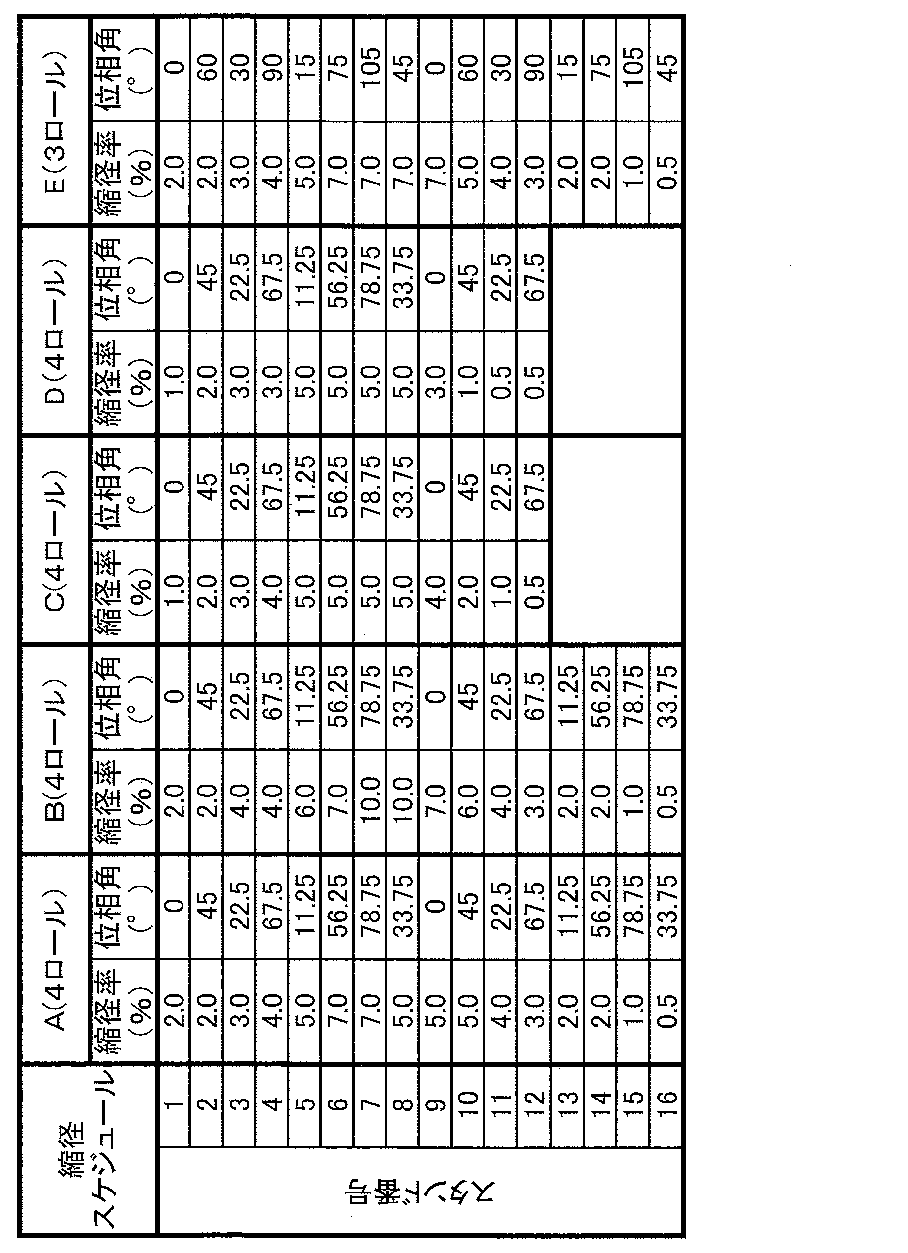
- Table 2 shows the diameter reduction schedule. Further, FIG. 7 is a plan view of the rolling roll for explaining the phase angle of the rolling roll shown in Table 2.
- phase angles shown in Table 2 are within 0 to 90 ° counterclockwise with respect to the center of the steel pipe from the ceiling of each stand 16 as shown in FIG. 7 for the patterns A to D of 4 rolls. It refers to the angle (°) in the circumferential direction from the ceiling of the center of the caliber (bottom of the caliber) of a rolling roll 15.
- the phase angle shown in Table 2 is the angle in the circumferential direction from the ceiling of the caliber bottom of the rolling roll 15 located within 0 to 120 ° counterclockwise from the ceiling of each stand 16. °).
- Tables 3 and 4 show the steel pipe Nos. The diameter reduction conditions including the diameter reduction pattern when A-1 to A-19 and B-1 to B-19 are manufactured are shown.
- the charging positions of the steel pipes shown in Tables 3 and 4 into the rolling roll are also shown in FIG. 8 for each diameter reduction pattern. Each angle was determined counterclockwise from the ceiling in the rolling direction (see also FIG. 7).
- the phase angles of the 5th to 10th stands having a reduction ratio of 5.0% or more are 11.25 ° and 56.
- the seam electric stitch welding seam
- the seam is not included in the range of ⁇ 5.0 ° of 25 °, 78.75 °, 33.75 °, 0 °, and 45 °
- condition P When the charging position of the seam (electric sewing welded seam) is not included in the range, the range of ⁇ 5.0 ° from the caliber center of the roll and 360 ° to the left and right from the caliber center under the manufacturing conditions of the present invention, respectively.
- the steel pipe No. A-1 and B-1 satisfy the condition P because the charging position 18 ° is not included in the above range.
- Steel pipe No. A-2 and B-2 satisfy the condition P because 23 °, which is obtained by subtracting 90 ° from the charging position 113 °, is not included in the above range.
- Steel pipe No. A-3 and B-3 satisfy the condition P because 25 °, which is obtained by subtracting 90 ° ⁇ 2 from the charging position 205 °, is not included in the above range.
- Steel pipe No. A-4 and B-4 satisfy the condition P because 67 °, which is obtained by subtracting 90 ° ⁇ 3 from the charging position of 337 °, is not included in the above range.
- A-5 and B-5 satisfy the condition P because the charging position 70 ° is not included in the above range.
- Steel pipe No. A-6 and B-6 satisfy the condition P because 18 °, which is obtained by subtracting 90 ° from the charging position 108 °, is not included in the above range.
- Steel pipe No. A-10 and B-10 satisfy the condition P because 23 °, which is obtained by subtracting 90 ° from the charging position 113 °, is not included in the above range.
- the steel pipe No. A-9 and B-9 do not satisfy the condition P because the charging position of 35 ° is included in the above range.
- Steel pipe No. A-11 and B-11 do not satisfy the condition P because the charging position of 12 ° is included in the above range.
- Steel pipe No. A-13 and B-13 do not satisfy the condition P because 75 °, which is obtained by subtracting 90 ° ⁇ 2 from the charging position 255 °, is included in the above range.
- Steel pipe No. A-14 and B-14 do not satisfy the condition P because the charging position 35 ° is included in the above range.
- Steel pipe No. A-15 and B-15 do not satisfy the condition P because the charging position 46 ° is included in the above range.
- the phase angles of the 5th to 8th stands having a diameter reduction ratio of 5.0% or more are 11.25 °, 56.25 °, and 78, respectively.
- the steel pipe No. A-7 and B-7 satisfy the condition P because 0 ° obtained by subtracting 90 ° ⁇ 2 from the charging position 180 ° is not included in the above range.
- Steel pipe No. A-8 and B-8 satisfy the condition P because 46 °, which is obtained by subtracting 90 ° ⁇ 2 from the charging position 226 °, is not included in the above range.
- Steel pipe No. A-12 and B-12 satisfy the condition P because 46 °, which is obtained by subtracting 90 ° ⁇ 2 from the charging position 226 °, is not included in the above range.
- the steel pipe No. A-16 and B-16 do not satisfy the condition P because the charging position 79 ° is included in the above range.
- the angles are -45 ° (evaluated as 75 °, which is -45 ° plus 120 °), 75 °, 45 °, 165 ° (evaluated as 45 °, which is 165 ° minus 120 °).
- the manufacturing conditions of the present invention when the charging position of the seam (electric stitch welding seam) is not included in the range of 0 ° and 120 ° (evaluated as 0 ° obtained by subtracting 120 ° from 120 °). The above condition P is satisfied.
- Steel pipe No. A-17 and B-17 satisfy the condition P because the charging position 23 ° is not included in the above range.
- the steel pipe No. A-18 and B-18 do not satisfy the condition P because 45 °, which is obtained by subtracting 120 ° from the charging position of 165 °, is included in the above range.
- Steel pipe No. A-19 and B-19 do not satisfy the condition P because 102 °, which is obtained by subtracting 120 ° ⁇ 2 from the charging position 342 °, is included in the above range.
- Tables 3 and 4 show the target outer diameter as a product, the target plate thickness, and the outer diameter after the actual diameter reduction. Further, Ts (MAX) , Ts (MIN) , Tb (ave) , and Db (ave) were measured from the cross section of each steel pipe, and W and H were calculated.
- the induction hardening treatment was performed by heating under the conditions of a heating temperature of 950 ° C. and a holding time of 1 s, and cooling with water.
- the tempering treatment was held at 190 ° C. for 1 hour and air-cooled.
- a tensile test was carried out to determine the tensile strength TS and r value.
- a tensile test piece of JIS No. 12A was taken from the base material region of the steel pipe, and a strain gauge having a gauge length of 2 mm was attached to the test. From the result of this tensile test, the tensile strength TS was determined.
- a tubular torsional fatigue test piece (length 450 mm) was collected from the obtained reduced-diameter rolled steel pipe and subjected to a torsional fatigue test.
- the torsional fatigue test is performed under the conditions of load stress (outer surface): 600 MPa, stress ratio: -1 (both swings), frequency 2 Hz, waveform: sine wave, and the number of repetitions until breakage is measured to evaluate fatigue resistance characteristics. bottom.
- the number of times until breaking is 2.0 times or more as compared with the comparative example of the same product size (the combination of the target wall thickness and the target outer diameter is the same) and the same steel type with the same diameter reduction schedule. It was judged that the twisted fatigue characteristics were improved.
- the electric resistance sewn steel pipe was used as a bare pipe and cold drawing was performed. Specifically, a plug was inserted inside the steel pipe and drawn out using a die. At this time, if the inner diameter of the electrosewn steel pipe protrudes and a scratching defect called galling of the plug is formed on the plug, it causes a defect when another steel pipe is processed. As an evaluation method, when the cold drawing process was performed, it was visually confirmed whether or not the plug surface had a defect, and the presence or absence of the defect was determined. Those without flaws were judged to be excellent in workability.
- Tables 3 and 4 show the steel No. As a result of A, Table 4 shows the steel No. This is the result of B.
- H / W is 0.10 or less
- the r value is 1.0 or more.
- the steel pipe of the example of the present invention has no flaws on the plug surface, is excellent in workability, and has improved torsional fatigue characteristics in a high load test as compared with the conventional electrosewn steel pipe.
- the steel pipe No. which is a comparative example.
- the charging position of the seam does not satisfy the above condition P, the H / W is out of the range of the present invention, and the desired torsional fatigue resistance property cannot be obtained.
- the steel pipe No. in A-10 and B-10 the heating temperature in reduced diameter rolling was less than 650 ° C., the r value was less than 1.0, and the desired processability could not be obtained.
- the charging position of the seam does not satisfy the above condition P, Ts (MAX) / Tb (Ave) is out of the scope of the present invention, and cold drawing is performed. Occasionally there was a flaw in the plug.
- the steel pipe No. The cumulative diameter reduction ratio of A-12 and B-12 was less than 30%, the r value was less than 1.0, and the desired processability could not be obtained.
- the steel pipe No. in A-13 and B-13 the charging position of the seam (electric stitch welding seam) does not satisfy the above condition P, the H / W is out of the range of the present invention, and the desired torsional fatigue resistance property cannot be obtained. rice field.
- the charging position of the seam does not satisfy the above condition P, and H / W and Ts (MAX) / Tb (Ave) are outside the scope of the present invention.
- the desired torsional fatigue resistance could not be obtained, and a flaw occurred in the plug during cold drawing.
- the steel pipe No. In A-15 and B-15, the charging position of the seam (electric stitch welding seam) does not satisfy the above condition P, the H / W is out of the range of the present invention, and the desired torsional fatigue resistance property cannot be obtained. rice field.
- the charging position of the seam (electric stitch welding seam) does not satisfy the above condition P, the H / W is out of the range of the present invention, and the desired torsional fatigue resistance property cannot be obtained. rice field.
- the steel pipe No. In A-18 and B-18 the charging position of the seam (electric stitch welding seam) does not satisfy the above condition P, the H / W is out of the range of the present invention, and the desired torsional fatigue resistance property cannot be obtained. rice field.
- the steel pipe No. In A-19 and B-19 the charging position of the seam (electric stitch welding seam) does not satisfy the above condition P, Ts (MAX) / Tb (Ave) is out of the scope of the present invention, and cold drawing is performed. Occasionally there was a flaw in the plug.
Landscapes
- Engineering & Computer Science (AREA)
- Mechanical Engineering (AREA)
- Chemical & Material Sciences (AREA)
- Organic Chemistry (AREA)
- Crystallography & Structural Chemistry (AREA)
- Materials Engineering (AREA)
- Metallurgy (AREA)
- Thermal Sciences (AREA)
- Physics & Mathematics (AREA)
- General Engineering & Computer Science (AREA)
- Manufacturing & Machinery (AREA)
- Heat Treatment Of Steel (AREA)
- Heat Treatment Of Articles (AREA)
- Butt Welding And Welding Of Specific Article (AREA)
Abstract
Description
これらのスタビライザー等の自動車用部品は、曲げ加工を施すため、高い加工性が要求され、また、製品としての使用中に曲げ、ねじり応力が作用し続けるため、優れた疲労特性(以下、耐ねじり疲労特性とも記す)も要求されている。
本発明は上記の課題を解決すべく、加工性と耐ねじり疲労特性に優れた電縫鋼管の技術を提供することを目的とする。
そして、本発明者らは上記の目的を達成するために、鋼管を熱間で縮径圧延する方法において、電縫溶接継目部付近の内径形状を向上させるための各種方策について鋭意研究した。その結果、縮径圧延工程の圧延ロールと縮径圧延中の鋼管の電縫溶接継目部の位置により電縫溶接継目部付近の内径形状が変化することを知見した。そして、縮径圧延工程時、圧延ロールへの鋼管の装入位置の適切化により、内径形状が良好になり、高い加工性と疲労特性向上の双方を実現できることを見出した。
[1]管長手方向に形成された電縫溶接継目部から管周方向に±10°までの領域であるシーム領域と、該シーム領域以外の母材領域とからなる電縫鋼管であって、
管長手方向のr値が1.0以上であり、
前記シーム領域の肉厚最小値Ts(MIN)(mm)及び前記母材領域の肉厚平均値Tb(Ave)(mm)の差(Tb(Ave)-Ts(MIN))であるH(mm)と、前記シーム領域の管内面の弧長W(mm)とが、以下の式(1)を満たし、
前記シーム領域の肉厚最大値Ts(MAX)(mm)と、前記Tb(Ave) (mm)とが、以下の式(2)を満たす電縫鋼管。
H/W≦0.10 ・・・式(1)
Ts(MAX)/Tb(Ave)≦1.05 ・・・式(2)
[2]前記Tb(Ave) (mm)と、前記母材領域の管外径平均値Db(Ave)(mm)とが、以下の式(3)を満たす前記[1]に記載の電縫鋼管。
(Tb(Ave)/Db(Ave))×100≧15% ・・・式(3)
[3]前記r値は、前記母材領域における管長手方向のr値である前記[1]又は[2]に記載の電縫鋼管。
[4]前記[1]~[3]のいずれか一つに記載の電縫鋼管を製造する方法であって、
鋼帯に成形を施してオープン管とし、
該オープン管に対して電縫溶接を施して素管とし、
該素管に対して、650℃以上の加熱温度で加熱し、累積縮径率が30%以上である縮径圧延を行い、
前記縮径圧延で、縮径率が5.0%以上となるロールスタンドでは、ロールのカリバー中心から±5.0°の範囲及びカリバー中心から左右にそれぞれ360°/(n×2)の位置から±5.0°(nは1スタンドあたりのロール数)の範囲に電縫溶接継目部を通過させない電縫鋼管の製造方法。
[5]前記[1]~[3]のいずれか一つに記載の電縫鋼管を用いてなる自動車用構造部材。
具体的に、本発明によれば、r値が1.0以上であって、更にプラグにかじりつきを発生させずに高い加工性を有し、従来よりも、耐ねじり疲労特性に優れた鋼管を製造でき、産業上格段の効果を奏する。本発明に係る電縫鋼管は、曲げ加工を施し、断面成型加工後に耐ねじり疲労特性を必要とするスタビライザーといった自動車用構造部材として好適である。
本発明の鋼管は、管長手方向に形成された電縫溶接継目部から管周方向に±10°までの領域であるシーム領域と、該シーム領域以外の母材領域とからなる電縫鋼管であって、管長手方向のr値が1.0以上であり、シーム領域の肉厚最小値Ts(MIN)(mm)及び母材領域の肉厚平均値Tb(Ave)(mm)の差(Tb(Ave)-Ts(MIN))であるH(mm)と、シーム領域の管内面の弧長W(mm)とが、以下の式(1)を満たし、シーム領域の肉厚最大値Ts(MAX)(mm)と、Tb(Ave) (mm)とが、以下の式(2)を満たすことを特徴とする、耐ねじり疲労特性に優れた電縫鋼管である。
H/W≦0.10 ・・・式(1)
Ts(MAX)/Tb(Ave)≦1.05 ・・・式(2)
母材領域6の肉厚平均値Tb(Ave)については、片球マイクロメータを使用し、電縫溶接継目部を0°とした際に、40°、80°、120°、160°、200°、240°、280°、及び320°の位置における母材領域6の肉厚を計測し、その値の平均値をTb(Ave)(mm)とする。
シーム領域3の管内面の弧長W(mm)は、次式(4)で定義する。
W(mm)=(縮径後のDb(Ave)-2×Tb(Ave))×20×π/360 ・・・式(4)
Ts(MIN)(mm)、Ts(MAX)(mm)は夫々、シーム領域3の肉厚最小値(図2中、符号5で示す位置で肉厚最小値となる。)、シーム領域3の肉厚の最大値(図2中、符号4で示す位置で肉厚最大値となる。)で定義される。
なお、Ts(MIN)(mm)、Ts(MAX)(mm)は、夫々、シーム領域3の区間の肉厚を1°刻みでポイントマイクロメータで計測し,その最小値、最大値とする。
また、本発明の電縫鋼管は、特に限定されないが、管外径平均値Db(Ave)は20.0~45.0mmであることが好ましい。
次に、r値(ランクフォード値)の範囲について説明する。本発明では、r値は、母材領域6における管長手方向のr値とすることができる。鋼管1の管長手方向のr値を1.0以上とすることにより、スタビライザーを製造する際に必要な加工性を満足する。一方、鋼管1の上記r値が1.0未満であると、鋼管1に曲げ加工を施すと座屈が生じ、所定の形状まで曲げ加工を行うことができない。よって、鋼管1の管長手方向のr値は、1.0以上とする。好ましくは、上記r値は1.3以上である。また,r値の上限は特に限定されないが、r値が高すぎることで管の周方向に変形が集中し、鋼管1に曲げ加工を施した際に鋼管断面が縮径し、くびれが生じて所望の形状が得られない可能性があるため、好ましくは2.0以下である。
次に、H(mm)とシーム領域3の管内面の弧長W(mm)との比H/Wの限定理由について説明する。
H(mm)とは、シーム領域3の肉厚最小値Ts(MIN)(mm)及び母材領域6の肉厚平均値Tb(Ave)(mm)の差(Tb(Ave)-Ts(MIN))であり、すなわち、H=Tb(Ave)-Ts(MIN)である。
図2に示すように、電縫鋼管1の内径形状に急峻なくぼみ(図2中、符号5参照)が存在すると、このくぼみに応力が集中し、耐ねじり疲労特性が著しく低下する。調査の結果、シーム領域3の急峻さの指標となるH/Wが、0.10以下であるとき、要求される耐ねじり疲労特性を満足することが分かった。
また、Hが負になる場合、すなわちTs(MIN)がTb(Ave)よりも大きい場合には、母材領域6よりも厚みが小さいくぼみがシーム領域3に存在しないため、耐ねじり疲労特性は低下しない。
よって、本発明では、シーム領域3の肉厚最小値Ts(min)(mm)と母材領域6の肉厚平均値Tb(Ave)(mm)の差(Tb(Ave)-Ts(MIN))で定義されるH(mm)とシーム領域3の弧長W(mm)の比(H/W)を0.10以下とする。
また、好ましくは、H/Wは、0.07以下であり、より好ましくは、0.05以下である。
また、好ましくは、H/Wは、-0.10以上であり、より好ましくは、-0.07以上である。
次に、シーム領域3の肉厚最大値Ts(MAX)(mm)とTb(Ave)(mm)の比(Ts(MAX)/Tb(Ave))の限定理由について説明する。耐ねじり疲労特性の観点では、シーム領域が母材領域6よりも肉厚が大きくなるほど、シーム領域3を起点とした破断は発生しにくくなる。
ここで、図3を参照する。図3は、シーム領域3の肉厚最大値Ts(MAX)が母材領域6の肉厚平均値Tb(Ave)よりも大きくなった際のシーム領域3の平面図である。
図3に示すように、Ts(MAX)(図3中、符号4参照)がTb(Ave)より大きくなることで、縮径圧延後に行われる冷間引抜加工時に問題が発生する場合がある。冷間引抜工程は、鋼管内にプラグを挿入し、ダイスを通して冷間で鋼管を引き抜く工程であり、シーム領域3の内径部において突起部が形成されることで、装入するプラグを傷つける問題や、内径部にプラグが当たらない部位が発生するという問題が起こる。
この点、シーム領域3の増肉の指標となるTs(MAX)/Tb(Ave)を1.05以下にすることで、これらの問題の発生を抑止できる。
よって、本発明では、シーム領域の肉厚最大値Ts(MAX)(mm)とTb(ave)(mm)の比(Ts(MAX)/Tb(Ave))を1.05以下とする。
また、好ましくは、Ts(MAX)/Tb(Ave)は、1.04以下であり、より好ましくは、1.03以下である。
また、好ましくは、Ts(MAX)/Tb(Ave)は、0.90以上であり、より好ましくは、0.95以上である。
本発明の鋼管では、さらに、Tb(Ave) (mm)と、母材領域の管外径平均値Db(ave)(mm)の比:(Tb(Ave)/Db(Ave))×100が15%以上であることが好ましい。
Tb(Ave)/Db(Ave)の限定理由は、次のとおりである。
Tb(Ave)/Db(Ave)を小さくすることで、重量を低減させられるが、(Tb(Ave)/Db(Ave))×100が15%未満であると、部品として要求される剛性及び強度を満足できない場合がある。そのため、棒鋼材の代替としては鋼管の寸法として(Tb(Ave)/Db(Ave))×100≧15%であることが好ましい。
また、好ましくは、(Tb(Ave)/Db(Ave))×100は、15.5%以上であり、より好ましくは、16.0%以上である。
また、好ましくは、(Tb(Ave)/Db(Ave))×100は、45%以下であり、より好ましくは、40%以下である。
Cは、強度増加に寄与する元素であり、添加することで耐疲労特性が向上するが、C含有量が0.55%を超えると溶接性が悪くなるため、安定した電縫溶接品質が得られなくなる場合がある。よって、C含有量は、0.55%以下とすることが好ましい。より好ましくは、C含有量は0.45%以下である。また、好ましくは、C含有量は0.2%以上である。
Siは、脱酸および固溶して鋼の強度を増加させる。このような効果を得るためには、Si含有量は0.01%以上とすることが好ましい。また、Si含有量が1.0%を超えると、鋼管の焼き入れ性が低下する場合がある。よって、Si含有量は、0.01~1.0%とすることが好ましい。より好ましくは、Si含有量は0.1%以上である。また、より好ましくは、Si含有量は0.4%以下である。
Mnは、焼き入れ性を向上させる効果があり、0.2%以上含有することでその効果を得る。しかし、Mn含有量が3.0%を超えると電縫溶接品質が悪化する場合がある。よって、Mn含有量は、0.2~3.0%とすることが好ましい。より好ましくは、Mn含有量は0.5%以上である。また、より好ましくは、Mn含有量は2.0%以下である。
Pは、粒界等に偏析し、靱性を低下させるため、本発明ではできるだけ低減させることが望ましいが、P含有量は0.01%までは許容できる。よって、P含有量は、0.01%以下とすることが好ましい。より好ましくは、P含有量は0.005%以下である。
Sは、鋼中で硫化物介在物として存在し、加工性、耐疲労特性を低下させる元素であるため、本発明ではできるだけ低減させることが望ましいが、S含有量は0.01%以下までは許容できる。よって、S含有量は、0.01%以下とすることが好ましい。より好ましくは、S含有量は0.005%以下である。
Crは、焼き入れ性を向上させる元素であり、鋼の強度を高め、疲労特性の向上に有効である。しかし、2.0%を超えてCrを含有すると、電縫溶接部継目部にCr酸化物が残存し、電縫溶接品質が低下する場合がある。よって、Cr含有量は、2.0%以下とすることが好ましい。より好ましくは、Cr含有量は0.5%以下である。また、好ましくは、Cr含有量は0.001%以上である。
Tiは、鋼中のNをTiNとして固定する作用を有する。しかし、Ti含有量が0.1%を超えると、鋼の加工性、靱性が低下する場合がある。よって、Ti含有量は、0.1%以下とすることが好ましい。より好ましくは、Ti含有量は0.04%以下である。また、好ましくは、Ti含有量は0.01%以上である。
Alは、脱酸に有効な元素であり、また、焼入れ時のオーステナイト粒の成長を抑制することで焼き入れ後の強度を確保するために必要な元素である。しかし、Al含有量が0.1%を超えると、効果が飽和し、Al系の介在物が増加することで疲労強度を低下させる場合がある。よって、Al含有量は、0.1%以下とすることが好ましい。より好ましくは、Al含有量は0.08%以下である。また、好ましくは、Al含有量は0.01%以上である。
Vは、微細な炭化物を形成して鋼の強度の増加に寄与する元素である。しかし、V含有量が0.5%を超えると効果が飽和し、含有量に見合う効果が期待できず、経済的に不利となる。よって、V含有量は、0.5%以下とすることが好ましい。より好ましくは、V含有量は0.3%以下である。また、好ましくは、V含有量は0.01%以上である。
Nbは、微細な炭化物を形成して鋼の強度の増加に寄与する元素である。しかし、Nb含有量が0.1%を超えると効果が飽和し、含有量に見合う効果が期待できず、経済的に不利となる。よって、Nb含有量は、0.1%以下とすることが好ましい。より好ましくは、Nb含有量は0.03%以下である。また、好ましくは、Nb含有量は0.001%以上である。
Moは、焼入れ性を向上させ、鋼の強度の増加に寄与する元素である。しかし、Mo含有量が1.0%を超えると効果が飽和し、含有量に見合う効果が期待できず、経済的に不利となる。よって、Mo含有量は、1.0%以下とすることが好ましい。より好ましくは、
Mo含有量は0.3%以下である。また、好ましくは、Mo含有量は0.01%以上である。
Cuは焼入れ性を高める元素であり、鋼の強度を高め、疲労強度の向上に有効である。しかし、2.0%を超えてCuを含有すると加工性が低下する場合がある。よって、Cu含有量は、2.0%以下とすることが好ましい。より好ましくは、Cu含有量は0.5%以下である。また、好ましくは、Cu含有量は0.001%以上である。
Niは焼入れ性を高める元素であり、鋼の強度を高め、疲労強度の向上に有効である。しかし、2.0%を超えてNiを含有すると加工性が低下する場合がある。よって、Ni含有量は、2.0%以下とすることが好ましい。より好ましくは、Ni含有量は0.5%以下である。また、好ましくは、Ni含有量は0.001%以上である。
Bは、微量で鋼の焼入れ性を高める元素である。しかし、B含有量が0.005%を超えるとその効果が飽和すると共に、粒界に偏析して粒界破壊を促進し疲労特性を低下させる。よって、B含有量は、0.005%以下とすることが好ましい。より好ましくは、B含有量は0.0050%以下である。また、好ましくは、B含有量は0.0003%以上である。
Nは、鋼中に不可避的に含有される元素であるが、鋼中の窒化物形成元素と結合し、結晶粒の粗大化抑制、さらには焼戻し後の強度増加に寄与する。しかし、N含有が0.01%を超えると電縫溶接継目部の靱性を低下させ、加工性が悪化する。よって、N含有量は、0.01%以下とすることが好ましい。より好ましくは、N含有量は0.005%以下である。
次に、上記の鋼管の製造方法について、図4を参照しながら説明する。
図4は本発明の電縫鋼管を製造するための設備の概略図を示す。
本発明では、まず、図4(a)に示すように、鋼帯7に対して連続成形機8等により連続成形を施してオープン管9とし、該オープン管に対して溶接手段10により電縫溶接を施して素管12とする。なお、本発明では、スクイズロール11で圧接しながら鋼帯7の周方向突合せ部を溶接手段10で電気抵抗溶接して、素管12を得てもよい。
また、素管12を、切断機13により所定の寸法に切断してもよい。
素管12を得た後、図4(b)に示すように、素管(管体)12に対して、加熱手段14により650℃以上の加熱温度で加熱し、圧延ロール(以下、単にロールとも記す。)15を用いて累積縮径率30%以上で縮径圧延を行う。圧延ロール15による縮径圧延については、複数のロールスタンド16-1、16-2・・・、16-N(Nは自然数)を用いて漸次縮径を行うようにすることができる。
縮径率(%)=100×(縮径前のDb(Ave)-縮径後のDb(Ave))/縮径前のDb(Ave) ・・・式(5)
より具体的に、累積縮径率は、以下の式(6)で得られる。
累積縮径率(%)=100×(第1スタンドでの縮径前のDb(Ave)-最終スタンドでの縮径後のDb(Ave))/第1スタンドでの縮径前のDb(Ave)・・・式(6)
上記加熱温度は、好ましくは700℃以上であり、より好ましくは800℃以上である。
また、上記加熱温度は、好ましくは1050℃以下であり、より好ましくは1000℃以下である。
上記累積縮径率は、好ましくは35%以上であり、より好ましくは40%以上である。
また、上記累積縮径率は、好ましくは90%以下であり、より好ましくは85%以下である。
ここでいう、第Nスタンドのロールスタンドでの縮径率は、以下の式(7)で得られる。
縮径率(%)=100×(第Nスタンドでの縮径前のDb(Ave)-第Nスタンドでの縮径後のDb(Ave))/第Nスタンドでの縮径前のDb(Ave) ・・・式(7)
それにより、1スタンドあたり縮径率が5.0%以上となる縮径圧延用のロールスタンドにおいて、図6に示すようにロール15のカリバー中心17から±5.0°の範囲およびカリバー中心17から左右にそれぞれ360°/(n×2)の位置から±5.0°(nは1スタンドあたりのロール数)の範囲を電縫溶接継目部2が回避するように素管12を装入したところ、変形が少なく、内径形状が良好に保たれることを知見した。
本発明では、加工性の観点から、管周方向に隣接するロール15において、左側のロール15の右端側となるカリバー中心17から360°/(n×2)の位置から±5.0°の領域と、右側のロール15の左端側となるカリバー中心17から360°/(n×2)の位置から±5.0°の領域とは、重なっていてよい。
表1に示す、2種類の鋼種A、Bの鋼帯に連続成形を施してオープン管とし、該オープン管に対して電縫溶接を施して素管とし、累積縮径率、加熱温度および縮径圧延用のロールスタンドへの装入位置を変化させて縮径圧延を行い、鋼管No.A-1~A-19、B-1~B-19を得た。鋼管No.A-1~A-19は鋼種Aに基づいて製造し、鋼管No.B-1~B-19は鋼種Bに基づいて製造した。
鋼管No.A-2、B-2は、装入位置113°から90°を引いた23°が上記範囲に含まれないため、条件Pを満たす。
鋼管No.A-3、B-3は、装入位置205°から90°×2を引いた25°が上記範囲に含まれないため、条件Pを満たす。
鋼管No.A-4、B-4は、装入位置337°から90°×3を引いた67°が上記範囲に含まれないため、条件Pを満たす。
鋼管No.A-5、B-5は、装入位置70°が上記範囲に含まれないため、条件Pを満たす。
鋼管No.A-6、B-6は、装入位置108°から90°を引いた18°が上記範囲に含まれないため、条件Pを満たす。
鋼管No.A-10、B-10は、装入位置113°から90°を引いた23°が上記範囲に含まれないため、条件Pを満たす。
鋼管No.A-11、B-11は、装入位置12°が上記範囲に含まれるため、条件Pを満たさない。
鋼管No.A-13、B-13は、装入位置255°から90°×2を引いた75°が上記範囲に含まれるため、条件Pを満たさない。
鋼管No.A-14、B-14は、装入位置35°が上記範囲に含まれるため、条件Pを満たさない。
鋼管No.A-15、B-15は、装入位置46°が上記範囲に含まれるため、条件Pを満たさない。
鋼管No.A-8、B-8は、装入位置226°から90°×2を引いた46°が上記範囲に含まれないため、条件Pを満たす。
鋼管No.A-12、B-12は、装入位置226°から90°×2を引いた46°が上記範囲に含まれないため、条件Pを満たす。
一方、鋼管No.A-16、B-16は、装入位置79°が上記範囲に含まれるため、条件Pを満たさない。
一方、鋼管No.A-18、B-18は、装入位置165°から120°を引いた45°が上記範囲に含まれるため、条件Pを満たさない。
鋼管No.A-19、B-19は、装入位置342°から120°×2を引いた102°が上記範囲に含まれるため、条件Pを満たさない。
評価方法としては、冷間での引抜加工を行った際に、プラグ表面に疵がついているか否かを目視で確認して、疵の有り無しを判断した。疵の無いものを加工性に優れていると判断した。
また、鋼管No.A-10、B-10は、縮径圧延における加熱温度が650℃未満であり、r値が1.0未満となり、所望の加工性を得られなかった。
また、鋼管No.A-11、B-11は、シーム(電縫溶接継目部)の装入位置が上記条件Pを満たさず、Ts(MAX)/Tb(Ave)が本発明の範囲外となり、冷間引抜加工時にプラグに疵が発生した。
また、鋼管No.A-12、B-12は、累積縮径率が30%未満であり、r値が1.0未満となり、所望の加工性を得られなかった。
また、鋼管No.A-13、B-13は、シーム(電縫溶接継目部)の装入位置が上記条件Pを満たさず、H/Wが本発明の範囲外となり、所望の耐ねじり疲労特性を得られなかった。
また、鋼管No.A-14、B-14は、シーム(電縫溶接継目部)の装入位置が上記条件Pを満たさず、H/W及びTs(MAX)/Tb(Ave)が本発明の範囲外となり、所望の耐ねじり疲労特性を得られず、冷間引抜加工時にプラグに疵が発生した。
また、鋼管No.A-15、B-15は、シーム(電縫溶接継目部)の装入位置が上記条件Pを満たさず、H/Wが本発明の範囲外となり、所望の耐ねじり疲労特性を得られなかった。
また、鋼管No.A-16、B-16は、シーム(電縫溶接継目部)の装入位置が上記条件Pを満たさず、H/Wが本発明の範囲外となり、所望の耐ねじり疲労特性を得られなかった。
また、鋼管No.A-18、B-18は、シーム(電縫溶接継目部)の装入位置が上記条件Pを満たさず、H/Wが本発明の範囲外となり、所望の耐ねじり疲労特性を得られなかった。
また、鋼管No.A-19、B-19は、シーム(電縫溶接継目部)の装入位置が上記条件Pを満たさず、Ts(MAX)/Tb(Ave)が本発明の範囲外となり、冷間引抜加工時にプラグに疵が発生した。


2 電縫溶接継目部
3 シーム領域
4 シーム領域の肉厚が最大となる位置
5 シーム領域の肉厚が最小となる位置
6 母材領域
7 鋼帯
8 連続成形機
9 オープン管
10 溶接手段
11 スクイズロール
12 素管
13 切断機
14 加熱手段
15 圧延ロール
16 ロールスタンド(ただし末尾の数字はスタンド番号を示す)
17 カリバー中心
18 カリバー直径
Claims (5)
- 管長手方向に形成された電縫溶接継目部から管周方向に±10°までの領域であるシーム領域と、該シーム領域以外の母材領域とからなる電縫鋼管であって、
管長手方向のr値が1.0以上であり、
前記シーム領域の肉厚最小値Ts(MIN)(mm)及び前記母材領域の肉厚平均値Tb(Ave)(mm)の差(Tb(Ave)-Ts(MIN))であるH(mm)と、前記シーム領域の管内面の弧長W(mm)とが、以下の式(1)を満たし、
前記シーム領域の肉厚最大値Ts(MAX)(mm)と、前記Tb(Ave)(mm)とが、以下の式(2)を満たす電縫鋼管。
H/W≦0.10 ・・・式(1)
Ts(MAX)/Tb(Ave)≦1.05 ・・・式(2) - 前記Tb(Ave)(mm)と、前記母材領域の管外径平均値Db(Ave)(mm)とが、以下の式(3)を満たす請求項1に記載の電縫鋼管。
(Tb(Ave)/Db(Ave))×100≧15% ・・・式(3) - 前記r値は、前記母材領域における管長手方向のr値である請求項1又は2に記載の電縫鋼管。
- 請求項1~3のいずれか一項に記載の電縫鋼管を製造する方法であって、
鋼帯に成形を施してオープン管とし、
該オープン管に対して電縫溶接を施して素管とし、
該素管に対して、650℃以上の加熱温度で加熱し、累積縮径率が30%以上である縮径圧延を行い、
前記縮径圧延で、縮径率が5.0%以上となるロールスタンドでは、ロールのカリバー中心から±5.0°の範囲及びカリバー中心から左右にそれぞれ360°/(n×2)の位置から±5.0°(nは1スタンドあたりのロール数)の範囲に電縫溶接継目部を通過させない電縫鋼管の製造方法。 - 請求項1~3のいずれか一項に記載の電縫鋼管を用いてなる自動車用構造部材。
Priority Applications (8)
| Application Number | Priority Date | Filing Date | Title |
|---|---|---|---|
| KR1020227031001A KR102830472B1 (ko) | 2020-03-18 | 2021-03-15 | 전봉 강관, 그 제조 방법 및 자동차용 구조 부재 |
| MX2022011054A MX2022011054A (es) | 2020-03-18 | 2021-03-15 | Tubo de acero soldado por resistencia electrica, metodo de fabricacion del mismo, y miembro estructural de automovil. |
| JP2021530942A JP6954504B1 (ja) | 2020-03-18 | 2021-03-15 | 電縫鋼管、その製造方法および自動車用構造部材 |
| CA3169974A CA3169974A1 (en) | 2020-03-18 | 2021-03-15 | Electric resistance welded steel pipe, method for manufacturing the same, and automotive structural member |
| US17/910,993 US12173835B2 (en) | 2020-03-18 | 2021-03-15 | Electric resistance welded steel pipe, method for manufacturing the same, and automotive structural member |
| EP21770460.0A EP4098380B1 (en) | 2020-03-18 | 2021-03-15 | Electric resistance welded steel pipe, method for producing same, and structural member for automobile |
| CN202180020600.2A CN115243808B (zh) | 2020-03-18 | 2021-03-15 | 电阻焊钢管、其制造方法和汽车用结构构件 |
| ZA2022/08745A ZA202208745B (en) | 2020-03-18 | 2022-08-04 | Electric resistance welded steel pipe, method for manufacturing the same, and automotive structural member |
Applications Claiming Priority (2)
| Application Number | Priority Date | Filing Date | Title |
|---|---|---|---|
| JP2020047317 | 2020-03-18 | ||
| JP2020-047317 | 2020-03-18 |
Publications (1)
| Publication Number | Publication Date |
|---|---|
| WO2021187408A1 true WO2021187408A1 (ja) | 2021-09-23 |
Family
ID=77770939
Family Applications (1)
| Application Number | Title | Priority Date | Filing Date |
|---|---|---|---|
| PCT/JP2021/010334 Ceased WO2021187408A1 (ja) | 2020-03-18 | 2021-03-15 | 電縫鋼管、その製造方法および自動車用構造部材 |
Country Status (9)
| Country | Link |
|---|---|
| US (1) | US12173835B2 (ja) |
| EP (1) | EP4098380B1 (ja) |
| JP (1) | JP6954504B1 (ja) |
| KR (1) | KR102830472B1 (ja) |
| CN (1) | CN115243808B (ja) |
| CA (1) | CA3169974A1 (ja) |
| MX (1) | MX2022011054A (ja) |
| WO (1) | WO2021187408A1 (ja) |
| ZA (1) | ZA202208745B (ja) |
Cited By (1)
| Publication number | Priority date | Publication date | Assignee | Title |
|---|---|---|---|---|
| TWI811095B (zh) * | 2022-09-07 | 2023-08-01 | 璋釔鋼鐵廠股份有限公司 | 空心穩定桿製造方法 |
Families Citing this family (2)
| Publication number | Priority date | Publication date | Assignee | Title |
|---|---|---|---|---|
| CN116000097A (zh) * | 2023-02-03 | 2023-04-25 | 湖南科技大学 | 管材多向轧制缩径校准成型装置 |
| CN120603972A (zh) | 2023-02-09 | 2025-09-05 | 杰富意钢铁株式会社 | 热轧钢板和电阻焊钢管 |
Citations (7)
| Publication number | Priority date | Publication date | Assignee | Title |
|---|---|---|---|---|
| JPH11151524A (ja) * | 1997-11-21 | 1999-06-08 | Kawasaki Steel Corp | 鋼管の製造方法 |
| JP2001115238A (ja) * | 1999-08-06 | 2001-04-24 | Sumitomo Metal Ind Ltd | マルテンサイト系ステンレス鋼溶接鋼管 |
| JP2006274436A (ja) * | 2005-03-30 | 2006-10-12 | Jfe Steel Kk | 部品用の断面形状をもつ曲管用のフェライト系ステンレス鋼板および鋼管 |
| JP5845623B2 (ja) | 2010-05-27 | 2016-01-20 | Jfeスチール株式会社 | 耐ねじり疲労特性に優れた電縫鋼管及びその製造方法 |
| JP5942572B2 (ja) | 2012-05-08 | 2016-06-29 | Jfeスチール株式会社 | 耐疲労特性に優れた自動車部品用電縫溶接鋼管およびその製造方法 |
| WO2016143271A1 (ja) * | 2015-03-12 | 2016-09-15 | Jfeスチール株式会社 | 電縫溶接ステンレスクラッド鋼管およびその製造方法 |
| WO2019188224A1 (ja) * | 2018-03-29 | 2019-10-03 | Jfeスチール株式会社 | 中空スタビライザー製造用の電縫鋼管、中空スタビライザー、及びそれらの製造方法 |
Family Cites Families (20)
| Publication number | Priority date | Publication date | Assignee | Title |
|---|---|---|---|---|
| US1643227A (en) * | 1924-11-24 | 1927-09-20 | Smith Corp A O | Method of metallic arc welding |
| US1829638A (en) * | 1931-01-13 | 1931-10-27 | Andrew G Egler | Electrically welded jarred steel pipe |
| US2817364A (en) * | 1952-11-13 | 1957-12-24 | Thomas J Crawford | Welded tubing |
| DE2835373A1 (de) | 1978-08-11 | 1980-02-21 | Uralsky Nii Trubnoj Promy | Verfahren zum reduzieren und kalibrieren von schweissrohren sowie walzwerk zur durchfuehrung des verfahrens |
| US5184674A (en) * | 1990-12-26 | 1993-02-09 | High Performance Tube, Inc. | Inner ribbed tube and method |
| JP3519966B2 (ja) * | 1999-01-07 | 2004-04-19 | 新日本製鐵株式会社 | 低温靱性に優れた超高強度ラインパイプおよびその製造法 |
| WO2001010591A1 (en) * | 1999-08-06 | 2001-02-15 | Sumitomo Metal Industries, Ltd. | Martensite stainless steel welded steel pipe |
| CA2403830C (en) * | 2001-06-14 | 2009-06-30 | Kawasaki Steel Corporation | High-workability steel pipe and method of producing same |
| JP4779465B2 (ja) * | 2005-06-30 | 2011-09-28 | Jfeスチール株式会社 | 鋼管の曲がり防止方法 |
| JP4882415B2 (ja) * | 2006-02-24 | 2012-02-22 | Jfeスチール株式会社 | 電縫管のシーム熱処理設備 |
| RU2448796C1 (ru) * | 2008-03-31 | 2012-04-27 | ДжФЕ СТИЛ КОРПОРЕЙШН | Сварная стальная труба, изготовленная с применением высокоэнергоплотного луча, и способ ее изготовления |
| BR112012016055B1 (pt) * | 2010-09-14 | 2019-04-24 | Nippon Steel & Sumitomo Metal Corporation | Tubo de aço soldado espesso execelente em rigidez à baixa temperatura, método para fabricação de tubo de aço soldado espesso excelente em rigidez à baixa temperatura, e placa de aço para fabricar tubo de aço soldado espesso. |
| CN104395487B (zh) | 2012-05-25 | 2017-02-22 | 新日铁住金株式会社 | 空心稳定杆和空心稳定杆用钢管及其制造方法 |
| US9200730B2 (en) * | 2013-03-14 | 2015-12-01 | Tenaris Coiled Tubes, Llc | Fatigue resistant coiled tubing |
| US20160033059A1 (en) * | 2014-06-27 | 2016-02-04 | Ati Properties, Inc. | Flowforming corrosion resistant alloy tubes |
| CN106989216A (zh) * | 2016-01-20 | 2017-07-28 | 浙江三花智能控制股份有限公司 | 管件本体、管件及管件的加工方法 |
| US11332812B2 (en) | 2016-10-24 | 2022-05-17 | Jfe Steel Corporation | Electric resistance welded steel tubes for high-strength thin hollow stabilizers, and methods for manufacturing the same |
| KR101752733B1 (ko) * | 2017-01-19 | 2017-06-30 | 주식회사 에코파이프 | 이중 파이프의 제조방법 |
| CN109423580B (zh) * | 2017-08-30 | 2021-05-14 | 宝山钢铁股份有限公司 | 一种汽车空心稳定杆用钢管及其制造方法 |
| US12172487B2 (en) | 2018-06-27 | 2024-12-24 | Jfe Steel Corporation | Electric-resistance-welded steel pipe for producing hollow stabilizer, hollow stabilizer, and method for producing same |
-
2021
- 2021-03-15 CN CN202180020600.2A patent/CN115243808B/zh active Active
- 2021-03-15 CA CA3169974A patent/CA3169974A1/en active Pending
- 2021-03-15 US US17/910,993 patent/US12173835B2/en active Active
- 2021-03-15 WO PCT/JP2021/010334 patent/WO2021187408A1/ja not_active Ceased
- 2021-03-15 MX MX2022011054A patent/MX2022011054A/es unknown
- 2021-03-15 JP JP2021530942A patent/JP6954504B1/ja active Active
- 2021-03-15 EP EP21770460.0A patent/EP4098380B1/en active Active
- 2021-03-15 KR KR1020227031001A patent/KR102830472B1/ko active Active
-
2022
- 2022-08-04 ZA ZA2022/08745A patent/ZA202208745B/en unknown
Patent Citations (7)
| Publication number | Priority date | Publication date | Assignee | Title |
|---|---|---|---|---|
| JPH11151524A (ja) * | 1997-11-21 | 1999-06-08 | Kawasaki Steel Corp | 鋼管の製造方法 |
| JP2001115238A (ja) * | 1999-08-06 | 2001-04-24 | Sumitomo Metal Ind Ltd | マルテンサイト系ステンレス鋼溶接鋼管 |
| JP2006274436A (ja) * | 2005-03-30 | 2006-10-12 | Jfe Steel Kk | 部品用の断面形状をもつ曲管用のフェライト系ステンレス鋼板および鋼管 |
| JP5845623B2 (ja) | 2010-05-27 | 2016-01-20 | Jfeスチール株式会社 | 耐ねじり疲労特性に優れた電縫鋼管及びその製造方法 |
| JP5942572B2 (ja) | 2012-05-08 | 2016-06-29 | Jfeスチール株式会社 | 耐疲労特性に優れた自動車部品用電縫溶接鋼管およびその製造方法 |
| WO2016143271A1 (ja) * | 2015-03-12 | 2016-09-15 | Jfeスチール株式会社 | 電縫溶接ステンレスクラッド鋼管およびその製造方法 |
| WO2019188224A1 (ja) * | 2018-03-29 | 2019-10-03 | Jfeスチール株式会社 | 中空スタビライザー製造用の電縫鋼管、中空スタビライザー、及びそれらの製造方法 |
Cited By (1)
| Publication number | Priority date | Publication date | Assignee | Title |
|---|---|---|---|---|
| TWI811095B (zh) * | 2022-09-07 | 2023-08-01 | 璋釔鋼鐵廠股份有限公司 | 空心穩定桿製造方法 |
Also Published As
| Publication number | Publication date |
|---|---|
| KR102830472B1 (ko) | 2025-07-04 |
| US20230141285A1 (en) | 2023-05-11 |
| JPWO2021187408A1 (ja) | 2021-09-23 |
| CN115243808A (zh) | 2022-10-25 |
| MX2022011054A (es) | 2022-09-19 |
| EP4098380A1 (en) | 2022-12-07 |
| US12173835B2 (en) | 2024-12-24 |
| EP4098380B1 (en) | 2025-07-16 |
| KR20220136428A (ko) | 2022-10-07 |
| JP6954504B1 (ja) | 2021-10-27 |
| ZA202208745B (en) | 2023-12-20 |
| CA3169974A1 (en) | 2021-09-23 |
| EP4098380A4 (en) | 2023-07-12 |
| CN115243808B (zh) | 2025-08-12 |
Similar Documents
| Publication | Publication Date | Title |
|---|---|---|
| CN102959098B (zh) | 电焊钢管及其制造方法 | |
| JP6954504B1 (ja) | 電縫鋼管、その製造方法および自動車用構造部材 | |
| JP5765497B1 (ja) | 溶接部品質の優れた電縫鋼管及びその製造方法 | |
| JP6885472B2 (ja) | 中空スタビライザー製造用の電縫鋼管、及びその製造方法 | |
| JP6631758B1 (ja) | 中空スタビライザー製造用の電縫鋼管、中空スタビライザー、及びそれらの製造方法 | |
| JP2019116658A (ja) | 疲労強度に優れた電縫鋼管およびその製造方法 | |
| JP7338590B2 (ja) | 電縫鋼管の異形断面鋼管製造用素材としての使用 | |
| JP2019116659A (ja) | 疲労強度に優れた厚肉大径電縫鋼管およびその製造方法 | |
| JP4859240B2 (ja) | 中空スタビライザ用電縫鋼管の製造方法 | |
| JP6384637B1 (ja) | コイルドチュービング用電縫鋼管およびその製造方法 | |
| JP4442541B2 (ja) | ラインパイプ向け低yr電縫鋼管の製造方法 | |
| WO2009119570A1 (ja) | ラインパイプ用uoe鋼管及びその製造方法 | |
| JP4466320B2 (ja) | ラインパイプ用低降伏比電縫鋼管の製造方法 | |
| US9737962B2 (en) | Pipeline and manufacturing method thereof | |
| JP4910694B2 (ja) | 自動車構造部材用高張力溶接鋼管及びその製造方法 | |
| JP4984447B2 (ja) | ラインパイプ向け低yr電縫鋼管の製造方法 | |
| JP4859618B2 (ja) | 耐遅れ破壊性に優れた中空スタビライザの製造方法 | |
| JP5353760B2 (ja) | 変形特性に優れる電縫鋼管およびその製造方法 | |
| JPWO2018139095A1 (ja) | コイルドチュービング用熱延鋼板 | |
| JP2008188641A (ja) | 耐溶接軟化性及び疲労特性に優れた高強度溶接鋼管 |
Legal Events
| Date | Code | Title | Description |
|---|---|---|---|
| ENP | Entry into the national phase |
Ref document number: 2021530942 Country of ref document: JP Kind code of ref document: A |
|
| 121 | Ep: the epo has been informed by wipo that ep was designated in this application |
Ref document number: 21770460 Country of ref document: EP Kind code of ref document: A1 |
|
| ENP | Entry into the national phase |
Ref document number: 3169974 Country of ref document: CA |
|
| ENP | Entry into the national phase |
Ref document number: 20227031001 Country of ref document: KR Kind code of ref document: A |
|
| ENP | Entry into the national phase |
Ref document number: 2021770460 Country of ref document: EP Effective date: 20220902 |
|
| NENP | Non-entry into the national phase |
Ref country code: DE |
|
| WWG | Wipo information: grant in national office |
Ref document number: 2021770460 Country of ref document: EP |
|
| WWG | Wipo information: grant in national office |
Ref document number: 202180020600.2 Country of ref document: CN |