WO2021190180A1 - 时间同步方法、装置、计算机可读介质及电子设备 - Google Patents
时间同步方法、装置、计算机可读介质及电子设备 Download PDFInfo
- Publication number
- WO2021190180A1 WO2021190180A1 PCT/CN2021/075424 CN2021075424W WO2021190180A1 WO 2021190180 A1 WO2021190180 A1 WO 2021190180A1 CN 2021075424 W CN2021075424 W CN 2021075424W WO 2021190180 A1 WO2021190180 A1 WO 2021190180A1
- Authority
- WO
- WIPO (PCT)
- Prior art keywords
- tsn
- time
- information
- activation
- pdu session
- Prior art date
- Legal status (The legal status is an assumption and is not a legal conclusion. Google has not performed a legal analysis and makes no representation as to the accuracy of the status listed.)
- Ceased
Links
Images



Classifications
-
- H—ELECTRICITY
- H04—ELECTRIC COMMUNICATION TECHNIQUE
- H04J—MULTIPLEX COMMUNICATION
- H04J3/00—Time-division multiplex systems
- H04J3/02—Details
- H04J3/06—Synchronising arrangements
- H04J3/0635—Clock or time synchronisation in a network
- H04J3/0638—Clock or time synchronisation among nodes; Internode synchronisation
-
- H—ELECTRICITY
- H04—ELECTRIC COMMUNICATION TECHNIQUE
- H04W—WIRELESS COMMUNICATION NETWORKS
- H04W56/00—Synchronisation arrangements
- H04W56/001—Synchronization between nodes
- H04W56/0015—Synchronization between nodes one node acting as a reference for the others
-
- H—ELECTRICITY
- H04—ELECTRIC COMMUNICATION TECHNIQUE
- H04J—MULTIPLEX COMMUNICATION
- H04J3/00—Time-division multiplex systems
- H04J3/02—Details
- H04J3/12—Arrangements providing for calling or supervisory signals
-
- H—ELECTRICITY
- H04—ELECTRIC COMMUNICATION TECHNIQUE
- H04J—MULTIPLEX COMMUNICATION
- H04J3/00—Time-division multiplex systems
- H04J3/02—Details
- H04J3/06—Synchronising arrangements
- H04J3/0635—Clock or time synchronisation in a network
- H04J3/0638—Clock or time synchronisation among nodes; Internode synchronisation
- H04J3/0658—Clock or time synchronisation among packet nodes
-
- H—ELECTRICITY
- H04—ELECTRIC COMMUNICATION TECHNIQUE
- H04W—WIRELESS COMMUNICATION NETWORKS
- H04W76/00—Connection management
- H04W76/10—Connection setup
-
- H—ELECTRICITY
- H04—ELECTRIC COMMUNICATION TECHNIQUE
- H04W—WIRELESS COMMUNICATION NETWORKS
- H04W76/00—Connection management
- H04W76/30—Connection release
Definitions
- This application relates to the field of computer and communication technologies, and in particular, to a time synchronization method, device, computer readable medium, and electronic equipment.
- the R16 (Release16) version of the 5G (5th Generation, fifth-generation mobile communication technology) system introduced Time Sensitive Network (TSN) Time Sensitive Communication (TSC) to enable 5G systems to support Industrial automation manufacturing applications with precise time control.
- TSN Time Sensitive Network
- TSC Time Sensitive Communication
- the embodiments of the present application provide a time synchronization method, device, computer readable medium, and electronic equipment, which can achieve effective control of the time synchronization operation of the user equipment at least to a certain extent.
- a time synchronization method which includes: receiving a TSN configuration creation request sent by an AF (Application Function), where the TSN configuration creation request includes the identifier of the target user equipment and The first information used to indicate the trigger condition of TSN time synchronization; send a TSN authorization request to UDM (Unified Data Manager, unified data management), and the TSN authorization request is used to request the UDM to include the first
- the TSN activation request of the information is sent to the AMF (Access and Mobility Management Function) registered by the target user equipment, so as to send to the target user equipment through the AMF for TSN time synchronization Operational control signaling.
- AMF Access and Mobility Management Function
- a time synchronization method including: receiving a TSN authorization request, the TSN authorization request is used to request to update user subscription data of a target user equipment; and after confirming authorization to update the target user equipment
- the TSN activation subscription data contained in the updated user subscription data send a TSN activation request to the AMF to which the target user equipment is registered to instruct the AMF to send to the target user equipment
- a control signaling used to perform a TSN time synchronization operation and the TSN activation request includes first information used to indicate a TSN time synchronization trigger condition.
- a time synchronization method including: receiving a TSN activation request sent by UDM, the TSN activation request including first information for indicating a TSN time synchronization trigger condition; The first information is to send control signaling to the target user equipment corresponding to the current AMF to control the target user equipment to perform the TSN time synchronization operation.
- a time synchronization method including: receiving control signaling sent by AMF, the control signaling including first information for indicating a TSN time synchronization trigger condition; based on the The control signaling and the first information perform a TSN time synchronization operation.
- a time synchronization device including: a first receiving unit configured to receive a time-sensitive network TSN configuration creation request sent by an application function entity AF, where the TSN configuration creation request includes The identifier of the target user equipment and the first information used to indicate the TSN time synchronization trigger condition; the first sending unit is configured to send a TSN authorization request to the unified data management entity UDM, where the TSN authorization request is used to request the UDM to confirm After authorization, the TSN activation request including the first information is sent to the AMF registered by the target user equipment, so as to send the control signaling for performing the TSN time synchronization operation to the target user equipment through the AMF.
- a time synchronization apparatus including: a second receiving unit configured to receive a TSN authorization request, where the TSN authorization request is used to request to update user subscription data of a target user equipment; second The sending unit is configured to, after confirming authorization to update the user subscription data of the target user equipment, activate the subscription data according to the TSN activation subscription data contained in the updated user subscription data, and send TSN activation to the AMF registered to the target user equipment Request to instruct the AMF to send control signaling for performing a TSN time synchronization operation to the target user equipment, and the TSN activation request includes first information for indicating a TSN time synchronization trigger condition.
- a time synchronization device including: a third receiving unit configured to receive a TSN activation request sent by UDM, the TSN activation request including a trigger condition for indicating TSN time synchronization The first information; the third sending unit is configured to send control signaling to a target user equipment corresponding to the current AMF based on the first information, so as to control the target user equipment to perform a TSN time synchronization operation.
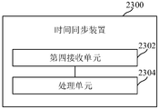
- a time synchronization device including: a fourth receiving unit configured to receive control signaling sent by AMF, and the control signaling includes information for indicating TSN time synchronization trigger conditions First information; a processing unit configured to perform a TSN time synchronization operation based on the control signaling and the first information.
- a computer-readable medium having a computer program stored thereon, and the computer program, when executed by a processor, implements the time synchronization method as described in the foregoing embodiment.
- an electronic device including: one or more processors; a storage device, configured to store one or more programs, when the one or more programs are When multiple processors are executed, the one or more processors are caused to implement the time synchronization method described in the foregoing embodiment.
- AF sends a TSN configuration creation request to NEF (Network Exposure Function), NEF sends a TSN authorization request to UDM, and UDN sends a TSN activation request to AMF , AMF sends control signaling to the target UE, so that the target UE can be controlled to perform a TSN time synchronization operation based on the relevant conditions triggered by the TSN, thereby effectively controlling the time synchronization operation of a user equipment or a group of user equipment.
- NEF Network Exposure Function
- UDM User Data Management Function
- UDN sends a TSN activation request to AMF
- AMF sends control signaling to the target UE, so that the target UE can be controlled to perform a TSN time synchronization operation based on the relevant conditions triggered by the TSN, thereby effectively controlling the time synchronization operation of a user equipment or a group of user equipment.
- Figure 1 shows a schematic diagram of a time synchronization process
- Figure 2 shows a schematic diagram of a 5G system supporting time synchronization in an external time domain
- Figure 3 shows a schematic diagram of the architecture of a time synchronization requirement proposed in the 5G R17 standard
- Fig. 4 shows a flowchart of a time synchronization method according to an embodiment of the present application
- Fig. 5 shows a flowchart of a time synchronization method according to an embodiment of the present application
- Fig. 6 shows a flowchart of a time synchronization method according to an embodiment of the present application
- Fig. 7 shows a flowchart of a time synchronization method according to an embodiment of the present application
- FIG. 8 shows a flowchart of a TSN time synchronization activation operation performed by UDM control according to an embodiment of the present application
- FIG. 9 shows a flowchart of a TSN time synchronization deactivation operation performed by UDM control according to an embodiment of the present application
- FIG. 10 shows a flow chart of AMF control for TSN time synchronization activation operation according to an embodiment of the present application
- FIG. 11 shows a flow chart of AMF control for TSN time synchronization deactivation operation according to an embodiment of the present application
- FIG. 12 shows a flowchart of a UE controlling a TSN time synchronization activation operation according to an embodiment of the present application
- FIG. 13 shows a flowchart of a UE controlling a TSN time synchronization deactivation operation according to an embodiment of the present application
- Figure 14 shows the process of UE registration to a new AMF.
- the old AMF transmits context information to the new AMF.
- Figure 15 shows a flow chart of the old AMF transmitting context information to the new AMF during network handover
- FIG. 16 shows a flowchart of NEF control for TSN time synchronization activation operation according to an embodiment of the present application
- FIG. 17 shows a flowchart of NEF control for TSN time synchronization deactivation operation according to an embodiment of the present application
- FIG. 18 shows a flowchart of NEF control for TSN time synchronization activation operation according to an embodiment of the present application
- FIG. 19 shows a flowchart of NEF control for TSN time synchronization deactivation operation according to an embodiment of the present application
- Fig. 20 shows a block diagram of a time synchronization device according to an embodiment of the present application
- Fig. 21 shows a block diagram of a time synchronization device according to an embodiment of the present application.
- Fig. 22 shows a block diagram of a time synchronization device according to an embodiment of the present application
- Fig. 23 shows a block diagram of a time synchronization device according to an embodiment of the present application.
- Fig. 24 shows a schematic structural diagram of a computer system suitable for implementing an electronic device according to an embodiment of the present application.
- clock difference measurement can use PTP (Precision Time Protocol), defined by IEEE (Institute of Electrical and Electronics Engineers) 1588 protocol)/gPTP (generalized Precision Time Protocol, general The precise time protocol is implemented by messages and algorithms defined by the IEEE 802.1AS protocol.
- PTP Precision Time Protocol
- IEEE Institute of Electrical and Electronics Engineers 1588 protocol
- gPTP Generalized Precision Time Protocol, general The precise time protocol is implemented by messages and algorithms defined by the IEEE 802.1AS protocol.
- the time data receiver (here assumed to be ES (End Station) is a device connected to a local area network or a metropolitan area network, acting as the source and source of traffic carried by the LAN or metropolitan area network /Or destination))
- the clock difference (Offset, hereinafter abbreviated as O)
- delay (Delay, hereinafter abbreviated as D) with the TSN clock domain A are measured through the received data packet ).
- a and B are intermediate variables; t 1 is the time value of TSN clock domain A carried in the Sync (synchronization message) message or Follow_up (follow message) message; t 2 , t 3 are the terminal stations The time value of the local clock, and t 2 represents the time value of the corresponding local clock when the ES receives a Sync message, t 3 represents the time value of the corresponding local clock when the ES sends a Delay_Req (delay request message) message; D represents the Sync message The transmission delay value from the TSN clock domain A to the ES; t 4 is the corresponding time value of the TSN clock domain A when the TSN clock domain A receives the Delay_Req message.
- Time synchronization with the master clock of TSN clock domain A is an algorithm for time synchronization between the ES of a TSN clock domain A and its master clock.
- the time of ES and the time of the master clock of clock domain A may differ more and more.
- the above measurement process can be repeated periodically to ensure that the time and clock of ES
- the time difference of the master clock of domain A is within a certain range. Due to the large number of ESs in a clock domain, if each ES performs this two-way signaling interaction with the master clock, it will greatly increase the implementation cost of the master clock and affect the stability and accuracy of its clock.
- the master clock can periodically send Sync (optionally Follow_up) messages whose destination address is a multicast address, and no longer conduct two-way signaling interaction with ES, and the network that transmits these messages accurately Calculate the transmission delay of the Sync (optionally Follow_up) message from the master clock to the ES, so that the ES is based on the delay provided by the network and the time value of the master clock on the Sync (optionally Follow_up) message, Time synchronization with the master clock can be achieved, and the specific implementation method can refer to the IEEE 802.1AS protocol.
- Figure 2 shows a schematic diagram of a 5G system supporting time synchronization of an external time domain (Time Domain).
- the 5G system is integrated into the TSN system as a TSN bridge.
- This "logical" TSN bridge includes a TSN converter for user-plane interaction between the TSN system and the 5G system.
- 5GS (5G system, 5G system) TSN converter functions include DS-TT (Device Side TSN Translator, device-side TSN converter) and NW-TT (Network TSN Translator, network TSN converter).
- the UE (User Equipment) in the 5G system is connected to one or more ESs in the TSN (Data Network) outside the 5G system through the DS-TT.
- UPF is connected to one or more ESs in TSN DN through NW-TT.
- the entire end-to-end 5G system can be regarded as an IEEE 802.1AS time-aware system.
- the 5G system has its own time system (such as GPS (Global Positioning System) time).
- 5G GM (5G Grand Master, 5G internal master clock) is used to represent the 5G system's clock domain (ie, 5G time domain) ).
- GNB in Figure 2 represents a 5G base station.
- Each device in the 5G system is synchronized to the 5G clock domain.
- the devices in the 5G system include: UPF (User Plane Function, user plane function), SMF, UE, DS-TT, NW-TT, NG RAN (NG Radio Access Network, 5G radio access network function equipment), etc.
- the NG interface is the interface between the radio access network and the 5G core network.
- the clock source of the external TSN Time Domain is outside the UPF.
- the device ES on the UE side of the TSN connects to the UE through DS-TT, accesses the 5G network, and then accesses the external TSN network through UPF and NW-TT on the UPF, and synchronizes time with the TSN clock source.
- the time synchronization message can be sent by TSN GM through Downlink (DL) data, that is, sent through the user plane of the UE.
- the downlink data including the time synchronization message of TSN GM arrives at the NW-TT/UPF first. , Enter the 5G system, then reach the UE and its DS-TT, and finally reach the ES on the UE side.
- TSN GM identifies its current time in the originTimestamp field of the time synchronization message it sends.
- NW-TT marks (marks) the time synchronization message that it has received the downlink data.
- update the CorrectionField field value in this packet to the original CorrectionField field value plus the transmission delay value between NW-TT and the Ethernet Bridge Port (port) that sent this message to NW-TT.
- the transmission delay between NW-TT and this Port can be obtained by the method shown in Figure 1 or by other means.
- DS-TT Before DS-TT forwards the downlink data to the ES, it subtracts the receiving time of the NW-TT added to the downlink data from its current time to obtain the transmission delay value of the time synchronization message in the entire 5G system.
- This delay value is accumulated with the previous transmission time from the TSN master clock to the NW-TT (in the CorrectionField field of the received time synchronization message) to obtain the updated transmission delay value, and the updated transmission time
- the delay value is marked on the CorrectionField field of the time synchronization message (that is, the total transmission delay of this message), and the reception time marked by the previous NW-TT is deleted. Then send this modified time synchronization message to ES.
- the ES marks the time delay value on the time synchronization message according to the DS-TT (that is, the CorrectionField field value on the time synchronization message), and directly adds the delay value on the time synchronization message to the delay value between DS-TT and ES.
- Transmission delay (the transmission delay between ES and DS-TT can be obtained through the method shown in Figure 1 or through other means), and the total transmission delay of this time synchronization message from the TSN master clock to the ES can be obtained.
- the total transmission delay plus the originTimestamp domain value on the time synchronization message can get a calculated time value, and then set its clock to this calculated time value, thereby realizing the time synchronization between the ES and TSN GM on the UE side.
- Figure 3 shows a schematic diagram of the architecture of a time synchronization requirement proposed in the 5G R17 standard.
- the ES on the UE side needs to synchronize the time to the TSN GM on the UPF/NW-TT side.
- TSN GM that is, the master clock of TSN
- the ES on the UPF/NW-TT side and other UEs (such as the one in Figure 3)
- the ES on the UE2) needs to be synchronized in time with the TSN GM on the UE1 side. That is, the TSN GM sends the time synchronization message through the uplink method through the user plane of UE1, and then reaches the UPF.
- the time synchronization message is sent to TSN ES through NW-TT.
- the UPF sends the time synchronization message to UE2 through the downlink data of UE2, and then sends the time synchronization message to TSN ES through the DS-TT of UE2.
- the DS-TT of UE1 records the time when UE1 receives the uplink (Uplink, UL) data packet sent by TSN GM and includes the time synchronization message, and sends the received time to the UL time synchronization.
- the CorrectionField field value in this data packet to the original CorrectionField field value plus the transmission delay value between DS-TT and TSN GM, where the transmission delay between DS-TT and TSN GM It can be obtained by the method shown in Figure 1 or by other means.
- NW-TT subtracts the time it took to receive this UL data packet from the receiving time of the UE1 DS-TT on the packet to obtain the transmission delay value of the entire UL data packet in the 5G system, and compares the delay value with the previous TSN
- the transmission time from GM to UE1 DS-TT (in the CorrectionField field of the received time synchronization message) is accumulated to obtain the updated transmission delay value, and the updated transmission delay value is added to this UL synchronization message
- delete the receiving time stamp on the DS-TT of UE1 at the same time delete the receiving time stamp on the DS-TT of UE1 at the same time, and then send this UL data packet to the TSN ES of the NW-TT connection on the right (including the TSN ES of the TSN time domain 1 and TSN time domain 2 ).
- the TSN ES of the NW-TT connection on the right side marks the time synchronization message according to the delay value (that is, the CorrectionField field value on the time synchronization message) marked on the time synchronization message by the NW-TT.
- the above delay value is directly added to the transmission delay between NW-TT and this TSN ES, you can get the total transmission delay of this synchronization message from TSN GM to TSN ES connected to NW-TT, this total transmission time Adding the originTimestamp domain value on the time synchronization message can obtain a calculated time value, and then set its clock to this calculated time value, thereby realizing time synchronization between TSN ES on the NW-TT side and TSN GM on the UE1 side.
- the UPF also sends the time synchronization message to UE2 through the user plane of UE2, and then reaches the DS-TT of UE2.
- UE2 DS-TT subtracts the time when it receives the downlink data packet including the time synchronization message from the reception time of the UE1 DS-TT on the downlink synchronization message data packet to obtain the entire data including the time synchronization message
- the transmission delay value of the 5G system and add the transmission delay value to the previous transmission time from TSN GM to UE1 DS-TT (in the CorrectionField field of the received time synchronization message) to get the updated
- the transmission delay value, and the updated transmission delay value is marked on the CorrectionField field of the DL data packet containing the time synchronization message, and the receiving time label marked by UE1 DS-TT is deleted, and then this DL data packet is sent to UE2 TSN ES on DS-TT.
- the DS-TT of UE1 in Figure 3 is connected to TSN GM Domain 1 and TSN GM Domain 2 at the same time, but it is also possible that the DS-TT of UE1 is connected to TSN GM Domain 1, and UE X’s DS-TT is connected to TSN GM Domain 2.
- the DS-TT of UE2 in Figure 3 is only connected to the End Station of one TSN GM Domain, but it is also possible that the DS-TT of UE2 can be connected to multiple End Stations, and each End Station corresponds to a different TSN GM. Domain.
- the DS-TT of a UE can be connected to one or more different TSN GM Domain GMs or End Stations; the DS-TT of a UE can be connected to a TSN GM Domain X GM, and a TSN GM Domain Y end at the same time. Station, or other connection methods.
- the embodiment of this application proposes that AF sends a TSN configuration creation request to NEF, NEF sends a TSN authorization request to UDM, UDM sends a TSN activation request to AMF, and AMF sends control signaling to the target UE to trigger the UE to perform TSN.
- the time synchronization activation or deactivation operation, and the time requirement for TSN time synchronization of the UE can be added to the trigger condition.
- Fig. 4 shows a flowchart of a time synchronization method according to an embodiment of the present application, and the time synchronization method may be executed by NEF.
- the time synchronization method includes at least step S410 to step S420, which are described in detail as follows:
- a TSN configuration creation request sent by an AF is received.
- the TSN configuration creation request includes an identifier of the target user equipment and first information used to indicate a TSN time synchronization trigger condition.
- the target user equipment is a user equipment that needs to perform TSN time synchronization.
- the first information used to indicate the TSN time synchronization trigger condition may include the following information: TSN clock domain identifier, first field information used to indicate whether it is uplink TSN synchronization or downlink TSN synchronization, used to indicate an activation operation or It is the second field information, network slice information, and data network name of the deactivation operation.
- the TSN clock domain identifier is used to identify the TSN clock domain that needs to be synchronized to; the first field information is used to indicate whether it is uplink TSN synchronization or downlink TSN synchronization. For example, the first value of the first field information indicates that it is uplink TSN.
- the second value of the first field information indicates that it is a downlink TSN synchronization; the second field information is used to indicate whether it is an activation operation or a deactivation operation, for example, the first value of the second field information indicates an activation operation, and the second field information
- the second value indicates the deactivation operation;
- the network slice information can be Single Network Slice Selection Assistance Information, referred to as S-NSSAI, which is used to identify a network slice;
- the data network name is Data Network Name, referred to as DNN.
- the TSN activation time information is used to indicate that the TSN time synchronization operation is performed immediately, or is used to indicate that the TSN time synchronization is performed after a predetermined time. Operation, or used to indicate the TSN time synchronization operation at a specified time point; if the first information does not include TSN activation time information, the first information is used to indicate that the TSN time synchronization operation is performed immediately.
- a TSN authorization request is sent to the UDM.
- the TSN authorization request is used to request the UDM to confirm the authorization and send the TSN activation request containing the first information to the AMF registered by the target user equipment, so as to send to the target user equipment through the AMF Control signaling used to perform TSN time synchronization operations.
- the NEF may convert the identification of the target user equipment from an external identification to a network identification. Wherein, if the identification of the target user equipment includes the external identification of a single user equipment, the external identification of the single user equipment is converted into the network identification of a single user equipment; if the identification of the target user equipment includes the external group identifications corresponding to multiple user equipments , The external group identification is converted into a list of network identifications of multiple user equipments.
- the external identifier of the user equipment may be, for example, a mobile phone number.
- the network identifier of the user equipment may be, for example, IMSI (International Mobile Subscriber Identity, International Mobile Subscriber Identity), GPSI (Generic Public Subscription Identifier), SUPI (Subscription Permanent Identifier), etc.
- NEF is sending TSN to UDM
- NEF is sending TSN to UDM
- TSN authorization request it is necessary to send a TSN authorization request to the UDM for each user equipment in the network identification list.
- FIG. 4 The embodiment shown in FIG. 4 is described from the perspective of NEF, and the time synchronization method of the embodiment of the present application will be described from the perspective of UDM in conjunction with FIG. 5 below.
- the time synchronization method can be executed by UDM, and includes at least the following steps S510 to S520, which are described in detail as follows:
- step S510 a TSN authorization request is received, and the TSN authorization request is used to request to update the user subscription data of the target user equipment.
- the UDM can receive the TSN authorization request sent by the NEF, and the process of sending the TSN authorization request by the NEF can refer to the technical solution of the foregoing embodiment.
- the UDM can determine whether to allow the NEF to request to add or modify the subscription data of the UE (target UE), and if allowed, it can add the user equipment subscription data.
- the user equipment subscription data may include the TSN clock domain identifier, the first field information used to indicate whether it is uplink TSN synchronization or downlink TSN synchronization, the second field information used to indicate whether it is an activation operation or a deactivation operation, network slice information, Data network name.
- the UDM can perform TSN activation and deactivation operations on the target user equipment based on the information of the user equipment subscription data.
- step S520 after confirming the authorization to update the user subscription data of the target user equipment, according to the TSN activation subscription data contained in the updated user subscription data, send a TSN activation request to the AMF registered to the target user equipment to indicate
- the AMF sends to the target user equipment control signaling used to perform the TSN time synchronization operation, and the TSN activation request includes first information used to indicate the TSN time synchronization trigger condition.
- the first information contained in the TSN activation request comes from the TSN authorization request sent by the NEF, but the original source is the TSN configuration creation request sent by the AF.
- the target user equipment is a user equipment that needs to perform TSN time synchronization.
- the first information may include the following information: TSN clock domain identifier, first field information used to indicate whether it is uplink TSN synchronization or downlink TSN synchronization, and second field information used to indicate whether it is an activation operation or a deactivation operation , Network slice information, data network name.
- the UDM can control the time for the target UE to perform the TSN time synchronization operation by controlling the timing of sending the TSN activation request to the AMF to which the target UE is registered. details as follows:
- the TSN activation request is immediately sent to the AMF to which the target user equipment is registered .
- the TSN authorization request does not contain the TSN activation time information.
- NEF has already performed time control when sending the TSN authorization request to UDM.
- UDM, AMF and target UE do not need
- UDM receives a TSN authorization request it immediately sends a TSN activation request to the AMF registered by the target UE; the other is that NEF, UDM, AMF, and target UE do not perform time control.
- NEF After receiving the TSN configuration creation request sent by AF, and performing necessary processing (such as converting the target UE's identity), directly send a TSN authorization request to UDM, and UDM immediately registers with the target UE when receiving the TSN authorization request
- the AMF sends a TSN activation request.
- the UDM will send the TSN activation request to the target user equipment registered to the target user equipment after receiving the predetermined time of the TSN authorization request. AMF.
- TSN activation time information contained in the TSN authorization request indicates that the TSN time synchronization operation is performed at the specified time point
- UDM will send the TSN activation request to the AMF registered to the target user equipment when the current time reaches the specified time point .
- TSN activation time information contained in the TSN authorization request indicates that the TSN time synchronization operation is performed at the specified time point, but the current time has exceeded the specified time point, UDM immediately sends the TSN activation request to the target user equipment registered to AMF.
- the UDM may not control the timing of the TSN time synchronization operation of the target UE. That is, after receiving the TSN authorization request, the UDM immediately generates a TSN activation request and sends it to the AMF registered by the target UE.
- the TSN activation request sent by UDM to AMF can contain TSN activation time information.
- the TSN activation time information comes from the TSN authorization request sent by NEF to UDM, but the original source is the TSN configuration sent by AF to NEF. Create a request.
- a target UE (for easy distinction, the target UE that has multiple AMFs registered with UDM is called the first target UE) may have multiple AMFs registered with UDM, such as registering for access
- the network conforms to the first AMF of 3GPP standards (such as 2G, 3G, 4G, 5G, etc.), and the access network does not conform to the second AMF of 3GPP standards (such as Wi-Fi).
- UDM when UDM sends a TSN activation request to the AMF registered by the first target UE, it can first send a TSN activation request to the first AMF whose access network conforms to the 3GPP standard, and indicate it in the activation response fed back by the first AMF
- the TSN activation request is sent to the second AMF whose access network does not conform to the 3GPP standard.
- the UDM can also send TSN activation requests to these multiple AMFs at the same time, and the activation responses fed back by the multiple AMFs indicate that none of the activations are successful, or the SMF feedback for the first target UE is not received within a set time.
- the TSN activation request is re-sent to multiple AMFs.
- FIG. 5 The embodiment shown in FIG. 5 is described from the perspective of UDM, and the time synchronization method of the embodiment of the present application will be described from the perspective of AMF with reference to FIG. 6 below.
- the time synchronization method can be executed by AMF and includes at least the following steps S610 to S620, which are described in detail as follows:
- step S610 a TSN activation request sent by UDM is received, and the TSN activation request includes first information for indicating a trigger condition for TSN time synchronization.
- the process of UDM sending the TSN activation request can refer to the technical solution of the foregoing embodiment.
- the first information contained in the TSN activation request comes from the TSN authorization request sent by the NEF to the UDM, but the initial source is the TSN configuration creation request sent by the AF to the NEF.
- the first information may include the following information: TSN clock domain identifier, first field information used to indicate whether it is uplink TSN synchronization or downlink TSN synchronization, second field information used to indicate whether it is an activation operation or a deactivation operation, Network slice information, data network name.
- step S620 based on the first information, control signaling is sent to the target user equipment corresponding to the current AMF to control the target user equipment to perform a TSN time synchronization operation.
- the target user equipment corresponding to the current AMF may be a target user equipment that has a signaling connection with the current AMF, or a target user equipment that has established a signaling connection with the current AMF before.
- the AMF when the AMF sends control signaling to the target user equipment corresponding to the current AMF, it needs to first detect whether the signaling connection between the target user equipment and the network is in the connection management idle state (CM-IDLE state), If it is detected that the target user equipment is in the connection management idle state, a service request process triggered by the network (Service Request) needs to be initiated to establish a signaling connection with the target user equipment; if it is detected that the target user equipment is in the connection management connection state (CM-CONNECTED state), then send control signaling to the target user equipment corresponding to the current AMF.
- CM-IDLE state connection management idle state
- Service Request a service request process triggered by the network
- the control signaling sent by the AMF to the corresponding target user equipment may be a PDU session establishment instruction ; If the second field information indicates a deactivation operation, the control signaling sent by the AMF to the corresponding target user equipment may be a PDU session release instruction or a PDU session modification instruction.
- the CM (Connection Management) state of the UE includes: CM-IDLE (i.e. idle state) and CM-CONNECTED (i.e. connected state).
- the CM reflects the UE’s signaling Connection characteristics.
- CM-IDLE In the idle state (CM-IDLE), there is no NAS (Non-Access Stratum, non-access stratum) signaling connection between the UE and the network, for example, does not include Radio Resource Control (Radio Resource Control, RRC) connection Connected to N1-AMF; in the connected state (CM-CONNECTED), there is a NAS signaling connection between the UE and the network, including RRC connection and N1-AMF connection
- RRC Radio Resource Control
- the first information contained in the TSN activation request can indicate both the activation operation and the deactivation operation.
- the control signaling sent by the AMF to the corresponding target UE is a PDU session establishment command.
- the specific sending modes are as follows:
- the AMF immediately sends the PDU session establishment to the target user equipment Instructions to instruct the target user equipment to establish a PDU session.
- the AMF receives the TSN activation request Send a PDU session establishment instruction to the target user equipment after a predetermined time to instruct the target user equipment to establish a PDU session.
- the original AMF can synchronize the TSN
- the activated context information is transmitted to the new AMF, so that the new AMF sends a PDU session establishment instruction to the target UE after the remaining TSN activation time arrives.
- the context information includes: TSN clock domain identifier, first field information used to indicate uplink TSN synchronization or downlink TSN synchronization, second field information used to indicate activation operation, network slice information, data network name, and TSN activation time information.
- the time value indicated by the TSN activation time information is the TSN remaining activation time, and the TSN remaining activation time is the difference between the predetermined time and the elapsed time (the elapsed time after the original AMF receives the TSN activation request).
- the original AMF can use the user equipment context transfer message (Namf_Communication_UEContextTransfer) to transmit the context information of the TSN synchronization activation to the new AMF; if it is the target during the network handover
- the original AMF can transmit the context information of the TSN synchronization activation to the new AMF through the Create User Equipment Context Request (Namf_Communication_CreateUEContext Request).
- the TSN activation time information indicates that the TSN time synchronization operation is performed at the specified time point, and the second field information indicates the activation operation, then the AMF reaches the specified time at the current time At this point, a PDU session establishment instruction is sent to the target user equipment to instruct the target user equipment to establish a PDU session.
- the original AMF can synchronize the activated context of the TSN
- the information is transmitted to the new AMF so that the new AMF sends a PDU session establishment instruction to the target user equipment when the current time reaches the specified time point;
- the context information includes: TSN clock domain identifier, used to indicate uplink TSN synchronization Or the first field information of the downlink TSN synchronization, the second field information used to indicate the activation operation, the network slice information, the data network name, and the TSN activation time information.
- the value indicated by the TSN activation time information is a specified time point.
- the technical solution of this embodiment can also be used in the TSN time synchronization process, even if the target UE is registered with a new AMF or the network handover process selects a new AMF for the target UE, it can still ensure the normal progress of the TSN time synchronization process.
- the original AMF can use the user equipment context transfer message (Namf_Communication_UEContextTransfer) to transmit the context information of the TSN synchronization activation to the new AMF; if it is the target user equipment during the network handover process If the new AMF is selected, the original AMF can transmit the context information of the TSN synchronization activation to the new AMF through the Create User Equipment Context Request (Namf_Communication_CreateUEContext Request).
- Namf_Communication_UEContextTransfer user equipment context transfer message
- the TSN activation time information indicates that the TSN time synchronization operation is performed at the specified time point, and the second field information indicates the activation operation, but the current time has exceeded the specified time point .
- the AMF immediately sends a PDU session establishment instruction to the target user equipment to instruct the target user equipment to establish a PDU session.
- the AMF immediately sends a PDU session establishment instruction to the target user equipment to instruct the target user equipment to establish a PDU session.
- the first information in the TSN activation request does not contain the TSN activation time information.
- NEF has already performed time control when sending the TSN authorization request to UDM.
- UDM, AMF and The target UE does not need to perform time control.
- UDM receives the TSN authorization request, it immediately sends a TSN activation request to the AMF registered by the target UE.
- the AMF After receiving the TSN activation request, the AMF immediately sends control signaling to the corresponding target UE;
- NEF does not perform time control, while UDM performs time control.
- UDM decides when to send a TSN activation request to AMF based on the TSN activation time information contained in the received TSN authorization request. After receiving the TSN activation request, it immediately sends control signaling to the corresponding target UE; another is that NEF, UDM, AMF and the target UE do not perform time control.
- the NEF receives the TSN sent by the AF After configuring the creation request and performing necessary processing (such as converting the target UE's identity), it sends a TSN authorization request directly to UDM.
- UDM receives the TSN authorization request, it immediately sends a TSN activation request to the AMF registered by the target UE. After receiving the TSN activation request, the AMF immediately sends control signaling to the corresponding target UE.
- the PDU session establishment instruction sent by the AMF may include the following parameters: TSN clock domain identifier, first field information used to indicate uplink TSN synchronization or downlink TSN synchronization, and used to indicate activation operation The second field information, network slice information, data network name. These parameters and their values come from the first information contained in the TSN activation request received by the AMF.
- the AMF may also send a PDU session establishment instruction containing TSN activation time information to the corresponding target UE, and the value of the TSN activation time information From the first information contained in the TSN activation request received by the AMF.
- the AMF does not perform time control operations, but sends a PDU session establishment instruction containing TSN activation time information to the target UE to instruct the target UE to initiate the PDU session establishment process at the corresponding time.
- the control signaling sent by AMF to the corresponding target UE is a PDU session release instruction or a PDU session modification instruction.
- the specific sending methods are as follows Several situations:
- the AMF immediately sends the PDU session to the target user equipment
- the release instruction or the PDU session modification instruction is used to instruct the target user equipment to initiate the PDU session release process or initiate the PDU session modification process.
- the AMF receives the TSN activation After the requested predetermined time, send a PDU session release instruction or a PDU session modification instruction to the target user equipment to instruct the target user equipment to initiate a PDU session release process or initiate a PDU session modification process.
- the original AMF can synchronize the TSN
- the activated context information is transmitted to the new AMF, so that the new AMF sends a PDU session release instruction or a PDU session modification instruction to the target user equipment after the remaining TSN activation time arrives.
- the context information includes: TSN clock domain identifier, first field information for indicating uplink TSN synchronization or downlink TSN synchronization, second field information for indicating deactivation operation, network slice information, and data network name And TSN activation time information.
- the time value indicated by the TSN activation time information is the TSN remaining activation time, and the TSN remaining activation time is the difference between the predetermined time and the elapsed time (the elapsed time after the original AMF receives the TSN activation request).
- the technical solution of this embodiment ensures that during the TSN time synchronization processing, even if the target UE registers with a new AMF or the network handover process selects a new AMF for the target UE, the normal progress of the TSN time synchronization processing can still be ensured.
- the signaling of sending context information can refer to the technical solutions of the foregoing embodiments, and details are not described herein again.
- the AMF reaches the specified time at the current time At the time point, the PDU session release instruction or the PDU session modification instruction is sent to the target user equipment to instruct the target user equipment to initiate the PDU session release process or initiate the PDU session modification process.
- the original AMF can synchronize the activated context of the TSN
- the information is transmitted to the new AMF, so that the new AMF sends a PDU session release instruction or a PDU session modification instruction to the target UE when the current time reaches a specified time point.
- the context information includes: TSN clock domain identifier, first field information used to indicate uplink TSN synchronization or downlink TSN synchronization, second field information used to indicate deactivation operation, network slice information, data network name, and TSN Activation time information.
- the time value indicated by the TSN activation time information is a specified time point.
- the signaling of sending context information can refer to the technical solutions of the foregoing embodiments, and details are not described herein again.
- the AMF immediately sends a PDU session release instruction or a PDU session modification instruction to the target user equipment to instruct the target user equipment to initiate a PDU session release process or initiate a PDU session modification process.
- first information does not contain TSN activation time information, and the second field information indicates a deactivation operation, immediately send a PDU session release instruction or a PDU session modification instruction to the target user equipment to instruct the target user equipment to initiate a PDU session Release process or initiate PDU session modification process.
- the PDU session release instruction or the PDU session modification instruction may include the following parameters: TSN clock domain identifier, first field information used to indicate uplink TSN synchronization or downlink TSN synchronization, and The second field information, network slice information, and data network name of the deactivation operation. These parameters and their values come from the first information.
- the target UE after the AMF sends the PDU session release instruction or the PDU session modification instruction to the corresponding target UE, the target UE initiates the PDU session release process or the PDU session modification process.
- the AMF can also directly initiate the PDU session release process and modification process, which are specifically as follows:
- the AMF immediately initiates the PDU session release process or initiates PDU session modification process.
- the PDU session release process or the PDU session modification process refers to the PDU session release process or the PDU session modification process related to the target UE. The following similarities are the same, so we won't repeat them.
- the AMF receives the TSN activation After the requested predetermined time, initiate the PDU session release process or initiate the PDU session modification process.
- the original The AMF can transmit the context information of the TSN synchronization activation to the new AMF, so that the new AMF initiates the PDU session release process or the PDU session modification process after the remaining TSN activation time arrives.
- the context information includes: TSN clock domain identifier, first field information for indicating uplink TSN synchronization or downlink TSN synchronization, second field information for indicating deactivation operation, network slice information, and data network name And TSN activation time information.
- the time value indicated by the TSN activation time information is the TSN remaining activation time, and the TSN remaining activation time is the difference between the predetermined time and the elapsed time (the elapsed time after the original AMF receives the TSN activation request).
- the signaling of sending context information can refer to the technical solutions of the foregoing embodiments, and details are not described herein again.
- the TSN activation time information indicates that the TSN time synchronization operation is performed at the specified time point, and the second field information indicates the deactivation operation, then the AMF reaches the specified time at the current time At the point in time, initiate a PDU session release process or initiate a PDU session modification process.
- the original AMF can be Transmit the context information of the TSN synchronization activation to the new AMF so that the new AMF initiates the PDU session release process or the PDU session modification process after the current time reaches the specified time point.
- the context information includes: TSN clock domain identifier, first field information used to indicate uplink TSN synchronization or downlink TSN synchronization, second field information used to indicate deactivation operation, network slice information, data network name, and TSN Activation time information.
- the time value indicated by the TSN activation time information is a specified time point.
- the signaling of sending context information can refer to the technical solutions of the foregoing embodiments, and details are not described herein again.
- the AMF immediately initiates the PDU session release process or initiates the PDU session modification process.
- the AMF immediately initiates the PDU session release process or initiates the PDU session modification process.
- the AMF initiating the PDU session release process or initiating the PDU session modification process may be to generate PDU session update information.
- the PDU session update information contains the identifier of the target TSN clock domain that needs to be deactivated. Then the AMF sends the PDU session update information to the SMF, so that the SMF instructs the user plane function entity to stop forwarding the TSN time synchronization data of the target TSN clock domain to the target user equipment.
- the PDU session established by the user equipment supports the time synchronization operation of multiple TSN clock domains.
- the AMF can initiate the PDU session modification process; if the first information contains the target TSN clock domain and network slice that need to be deactivated The information and data network names respectively match the TSN clock domain, network slice information, and data network name of the PDU session established by the target user equipment, and the target TSN clock domain that needs to be deactivated is the last TSN clock domain in the PDU session, then AMF can initiate the PDU session release process.
- the AMF may also send a PDU session release instruction or a PDU session modification instruction containing TSN activation time information to the corresponding target UE, and the The value of the TSN activation time information comes from the first information contained in the TSN activation request received by the AMF.
- AMF does not perform time control operations, but sends a PDU session release instruction or a PDU session modification instruction containing TSN activation time information to the target UE to instruct the target UE to initiate the PDU session release process at the corresponding time Or PDU session modification process.
- FIG. 6 The embodiment shown in FIG. 6 is described from the perspective of AMF, and the time synchronization method of the embodiment of the present application will be described from the perspective of UE (target UE) in conjunction with FIG. 7 below.
- the time synchronization method may be executed by the UE, and includes at least the following steps S710 to S720, which are described in detail as follows:
- step S710 the control signaling sent by the AMF is received, and the control signaling includes the first information used to indicate the TSN time synchronization trigger condition.
- the process of AMF sending control signaling can refer to the technical solution of the foregoing embodiment.
- the control signaling may include a PDU session establishment instruction, a PDU session release instruction, and a PDU session modification instruction.
- the first information contained in the control signaling comes from the TSN activation request sent by the UDM to the AMF, but the initial source is the TSN configuration creation request sent by the AF to the NEF.
- the first information may include the following information: TSN clock domain identifier, first field information used to indicate whether it is uplink TSN synchronization or downlink TSN synchronization, second field information used to indicate whether it is an activation operation or a deactivation operation, Network slice information, data network name.
- step S720 a TSN time synchronization operation is performed based on the control signaling and the first information.
- the control signaling is a PDU session establishment instruction.
- the process of performing the TSN time synchronization operation based on the control signaling and the first information can have the following situations:
- the PDU session establishment process initiated by the UE when establishing the PDU session can refer to section 4.3.2 of the 3GPP protocol TS23.502.
- the PDU session establishment request sent by the UE when establishing a PDU session may include the following parameters.
- the following parameters and parameter values are derived from the first information: TSN clock domain identifier, which is used to indicate whether it is uplink TSN synchronization or downlink TSN synchronization.
- the first information in the control signaling does not include the TSN activation time information.
- NEF has already performed time control when sending the TSN authorization request to UDM.
- UDM, AMF and The UE does not need to perform time control.
- UDM receives a TSN authorization request, it immediately sends a TSN activation request to the AMF registered by the UE.
- the AMF After receiving the TSN activation request, the AMF immediately sends a PDU session establishment instruction to the corresponding UE; another NEF does not perform time control, while UDM performs time control.
- UDM decides when to send a TSN activation request to AMF according to the TSN activation time information contained in the received TSN authorization request.
- AMF receives After the TSN activation request, it immediately sends a PDU session establishment instruction to the corresponding UE; the other is that NEF and UDM do not perform time control, but AMF performs time control. In this case, AMF according to the received TSN activation request
- the TSN activation time information included determines when to send a PDU session establishment instruction to the UE.
- the UE After receiving the PDU session establishment instruction, the UE immediately establishes a PDU session for TSN time synchronization operation; there is also a case of NEF, UDM, AMF and UE No time control is performed.
- NEF sends a TSN authorization request directly to UDM after receiving the TSN configuration creation request sent by AF and performing necessary processing (such as converting the UE's identity).
- TSN authorization request Upon receiving the TSN authorization request, it immediately sends a TSN activation request to the AMF registered by the UE. After receiving the TSN activation request, the AMF immediately sends a PDU session establishment instruction to the corresponding UE.
- the UE If the first information contains TSN activation time information, and the TSN activation time information indicates that the user equipment immediately performs a TSN time synchronization operation after receiving the PDU session establishment instruction, the UE immediately establishes a PDU session to perform the TSN time synchronization operation.
- the UE will receive the PDU session establishment instruction After a predetermined time, a PDU session is established to perform TSN time synchronization operations.
- the UE If the first information contains TSN activation time information, and the TSN activation time information indicates that the user equipment performs the TSN time synchronization operation at the specified time point, then when the current time reaches the specified time point, the UE establishes a PDU session for TSN time Synchronous operation.
- the UE If the first information contains TSN activation time information, and the TSN activation time information indicates that the user equipment performs TSN time synchronization operation at a specified time point, but the current time has exceeded the specified time point, the UE immediately establishes a PDU session for TSN Time synchronization operation.
- the UE may first detect whether it is in the connection management idle state. If the UE is in the connection management idle state, the Service Request process is executed to establish a signaling connection with AMF. After the signaling connection is established, the UE can establish a PDU session for TSN time synchronization operation; if the UE is in a connection management connection In the state, you can directly establish a PDU session to perform TSN time synchronization operations.
- the second field information indicates an activation operation
- the TSN activation time information in the first information indicates that the user equipment performs a TSN time synchronization operation after receiving the PDU session establishment instruction for a predetermined time
- the UE will receive the PDU session establishment instruction for the predetermined time based on The new AMF establishes a PDU session for TSN time synchronization operation. That is, the UE registers with the new AMF or the network switches to select the new AMF for the UE, and it will not affect the UE's TSN time synchronization operation.
- the UE may first detect when the current time reaches the specified time point Whether the UE is in the connection management idle state, if the UE is in the connection management idle state, the service request process is executed to establish a signaling connection with the AMF. After the signaling connection is established, the UE can establish a PDU session for TSN time synchronization; if the UE is in In the connection management connection state, you can directly establish a PDU session to perform TSN time synchronization operations.
- the TSN activation time information in the first information indicates that the user equipment performs the TSN time synchronization operation at the specified time point
- the UE if the current time does not reach the specified time point, and the UE is registered to the new AMF Or a new AMF is selected for the UE during the network handover, and when the current time reaches the specified time point, the UE establishes a PDU session based on the new AMF to perform the TSN time synchronization operation.
- the control signaling is a PDU session release instruction or a PDU session modification instruction.
- the process of performing TSN time synchronization operations based on the control signaling and the first information has the following situations:
- the UE immediately initiates the PDU session release process or the PDU session modification process when receiving the PDU session release instruction or the PDU session modification instruction.
- the UE initiated the PDU session release process can refer to the section 4.3.4.2 of the 3GPP protocol TS23.502; the UE initiates the PDU session modification process can refer to the section 4.3.2.2 of the 3GPP protocol TS23.502.
- the UE immediately initiates the PDU session release Process or initiate a PDU session modification process.
- the UE will receive The PDU session release process or the PDU session modification process is initiated after the predetermined time of the PDU session release instruction or the PDU session modification instruction.
- the UE initiates the PDU session release process when the current time reaches the specified time point or Initiate the PDU session modification process.
- the UE If the first information contains TSN activation time information, and the TSN activation time information indicates that the user equipment performs TSN time synchronization operation at a specified time point, but the current time has exceeded the specified time point, the UE immediately initiates the PDU session release process Or initiate the PDU session modification process.
- the generated PDU session modification request contains the identifier of the target TSN clock domain that needs to be deactivated, and then after the PDU session modification request is sent to the SMF, The SMF can instruct the user plane function entity to stop forwarding the TSN time synchronization data of the target TSN clock domain to the UE that sends the PDU session modification request.
- the PDU session established by the UE may support the time synchronization operation of multiple TSN clock domains.
- the UE initiates the PDU session modification process; if the first information contains the target TSN clock domain and network slice information that needs to be deactivated And the data network name respectively match the TSN clock domain, network slice information and data network name of the PDU session established by the UE, and the target TSN clock domain to be deactivated is the last TSN clock domain in the PDU session, the UE initiates It is the PDU session release process.
- the TSN activation time information in the first information indicates that the user equipment performs the operation after a predetermined time after receiving the PDU session release instruction or the PDU session modification instruction.
- TSN time synchronization operation then if the UE receives the PDU session release command or the PDU session modification command before the predetermined time, and the UE is registered to a new AMF or a new AMF is selected for the UE during the network handover, the UE is receiving After the predetermined time for the PDU session release instruction or the PDU session modification instruction, the PDU session release process or the PDU session modification process is initiated based on the new AMF.
- the second field information indicates the deactivation operation
- the TSN activation time information in the first information indicates that the UE performs TSN time synchronization operation at the specified time point
- the UE initiates the PDU session release process or the PDU session modification process based on the new AMF. That is, the UE registers with the new AMF or the network switches to select the new AMF for the UE, and it will not affect the UE's TSN time synchronization operation.
- UDM, AMF, and UE can all control the timing of the UE's TSN time synchronization operation, which will be described in detail below:
- the process of performing TSN time synchronization activation operation by UDM control includes the following steps:
- step S801 the AF sends a TSN configuration creation request to the NEF.
- the master clock of TSN domain 1 can send uplink gPTP messages of TSN clock domain 1 to UPF/NW-TT and TSN domain 2 through a UE (the UE is not the DS-TT/UE shown in Figure 8).
- the master clock can send downlink gPTP messages of TSN clock domain 2 to UPF/NW-TT through a terminal device (for example, another UE), and these messages are respectively used to perform TSN time synchronization operations in different TSN time domains.
- the specific process of step S801 can refer to section 6.8.3.1 "procedure for AF Requested TSN Synchronization Activation" in 3GPP protocol TS23.700-20V0.3.0 (the process of AF requesting TSN synchronization activation) Step 1.
- the TSN configuration creation request in the embodiment of this application includes Target ID (target ID), TSN Activation Time (TSN activation time), TSN Domain ID (TSN clock domain identifier), UL or DL TSN Synchronization (uplink TSN synchronization) Or downlink TSN synchronization), Activation/Deactivation Indicator (activation operation or deactivation operation indication), S-NSSAI, DNN. Since the embodiment shown in FIG. 8 is an activation operation of TSN time synchronization, the value of Activation/Deactivation Indicator is Activation.
- the Target ID refers to a specific UE or a group of UEs.
- the Target ID is usually SUPI, IMSI, GPSI, or other external application identifiers.
- the Target ID refers to a group of UEs, the Target ID is usually the External Group ID (External Group ID).
- the TSN Activation Time is used to indicate whether the TSN time synchronization activation (or deactivation) operation should be performed immediately, or the TSN time synchronization activation (or deactivation) operation should be performed X seconds after this message, or at a specified time Click to activate (or deactivate) TSN time synchronization.
- Step S802 NEF performs processing.
- the specific process of step S802 can refer to step 2 in section 6.8.3.1 "procedure for AF Requested TSN Synchronization Activation" in 3GPP protocol TS23.700-20V0.3.0.
- Step S803a NEF sends a Nudm_SDM_Get request to UDM.
- the Nudm_SDM_Get request may include the following parameters: Identifier Translation, Target ID, and AF Identifier.
- step S803b the UDM sends a Nudm_SDM_Get response to the NEF.
- the Nudm_SDM_Get response may include the following parameters: SUPI and optionally (optional) MSISDN (Mobile Station International Integrated Service Digital Network Number, Mobile Station International Integrated Service Digital Network Number).
- the Target ID may refer to a group of UEs. If the Target ID refers to a group of UEs, the Target ID is usually the External Group ID, then the reply of step S803b is the SUPI list and the optional MSISDN list. In this case, the following steps S804 to S813 need to be That is, each UE can perform similar operations.
- Step S804 NEF sends a TSN authorization request to UDM.
- the TSN authorization request may include related parameters in the TSN configuration creation request. For example, Target ID, TSN Activation Time, TSN Domain ID, UL or DL TSN Synchronization, Activation (indicating activation operation), S-NSSAI, DNN.
- Step S805 UDM performs processing.
- the UDM after receiving the TSN authorization request, can determine whether to allow NEF to request to add or modify the UE's subscription data. If allowed, it can add user equipment subscription data.
- the user equipment subscription data may include TSN Time domain identifier, first field information used to indicate uplink TSN synchronization or downlink TSN synchronization, second field information used to indicate activation or deactivation operation, network slice information, and data network name.
- the UDM can perform TSN activation and deactivation operations on the target user equipment based on the information of the user equipment subscription data.
- Step S806 UDM returns a TSN authorization response to NEF.
- step S807 the NEF returns a TSN configuration creation response to the AF.
- step S804 to step S807 can refer to step 3 to step 6 in section 6.8.3.1 "procedure for AF Requested TSN Synchronization Activation" in 3GPP protocol TS23.700-20V0.3.0 .
- step S808 the UDM sends a TSN activation request to the AMF.
- the TSN activation request contains relevant parameters in the TSN authorization request, such as Target ID, TSN Domain ID, UL or DL TSN Synchronization, Activation (indicating activation operation), S- NSSAI, DNN.
- the UDM immediately sends a notification to a UE (if the Target ID in step S801 refers to a single UE, then only to a single UE; if the Target ID in step S801 ID refers to the group ID. Then register the SUPI of each UE to the AMF of UDM and send a TSN activation request.
- This TSN activation request can include TSN Domain ID, UL or DL TSN Synchronization, Activation, S-NSSAI, DNN Wait. In this case, there may be no precedence between step S808, step S806, and step S807.
- the UDM will send the TSN activation request X seconds after receiving the TSN authorization request.
- TSN Activation Time indicates that the TSN time synchronization operation is performed at a specific time point
- UDM reaches this specific time
- a TSN activation request is sent. (If the specific time point is earlier than the current time point, UDM immediately sends a TSN activation request).
- a UE may have multiple AMFs registered on the UDM (usually there are two at most).
- the UDM may first send a message to the AMF whose RAT (Radio Access Technology, radio access technology) is 3GPP. If the registration message for the UE’s PDU session is not received in step S811, or the TSN activation response fed back by AMF to UDM in step S812 indicates that the activation is not successful (AMF can determine that the PDU session is not successfully established) Sending a TSN activation response indicating that the activation is not successful), then the message can be sent again to the AMF corresponding to the Non-3GPP RAT.
- RAT Radio Access Technology, radio access technology
- UDM can send TSN activation requests to these multiple AMFs at the same time, and then indicate in the TSN activation responses fed back by these multiple AMFs that none of the activations are successful, or that the SMF feedback PDU for the UE is not received within a set time During the session registration message, the TSN activation request is re-sent to these multiple AMFs.
- step S809 the AMF initiates a service request triggered by the network.
- the AMF can initiate a Service Request process triggered by the network to establish a signaling connection between the UE and the AMF. If the UE is already in the CM-CONNECTED state, there is no need to perform this step.
- step S810 the AMF sends a PDU session establishment instruction to the UE.
- the AMF may send a NAS message to the UE, requesting the UE to establish a PDU session.
- the PDU session establishment instruction may include: TSN Domain ID, UL or DL TSN Synchronization, Activation, S-NSSAI, and DNN.
- step S811 the UE initiates a PDU session establishment process.
- the UE initiates the PDU session establishment process with reference to section 4.3.2 of the 3GPP protocol TS23.502.
- the PDU Session Establishment Request (PDU session establishment request) in the N1 SM container initiated by the UE may include the following parameters: TSN Domain ID, UL or DL TSN Synchronization, Activation, S-NSSAI, DNN.
- the PDU session establishment request is transferred to the SMF through the AMF, and at the same time, the N1 message sent to the AMF includes the TSN Domain ID, S-NSSAI, and DNN.
- the SMF provides the S-NSSAI, DNN and TSN Domain ID when registering with the UDM, so UDM knows that the UE has successfully triggered the TSN domain ID by comparing the S-NSSAI, DNN and TSN Domain ID. Activation process.
- step S812 the AMF feeds back the TSN activation response to the UDM. It should be noted that this step is optional. If there is this step, the AMF can indicate whether the TSN time synchronization is successfully activated by feeding back the TSN activation response to the UDM.
- Step S813a if the TSN Domain ID is TSN clock domain 1, UPF/NW-TT sends the gPTP message of TSN clock domain 1 to the UE; step S813b, if the TSN Domain ID is TSN clock domain 2, then UPF/NW-TT Send the gPTP message of the TSN clock domain 2 to the UE; step S813c, if the TSN Domain ID indicates 5G Time Domain, the UPF/NW-TT sends the gPTP message of the 5G system clock domain to the UE.
- steps S813a to S813c can refer to 3GPP protocol TR23.700-020.
- UPF/NW-TT forwards TSN synchronization related data in different directions according to TSN Domain , So that the UE can perform TSN time synchronization processing.
- the process of performing a TSN time synchronization deactivation operation for UDM control includes the following steps:
- Step S901 AF sends a TSN configuration creation request to NEF.
- the master clock of TSN domain 1 can send uplink gPTP messages of TSN clock domain 1 to UPF/NW-TT through a UE (the UE is not the DS-TT/UE shown in Figure 9); TSN domain 2
- the master clock can send the downlink gPTP message of TSN clock domain 2 to UPF/NW-TT through the terminal device (for example, another UE);
- UPF/NW-TT sends the gPTP message of TSN clock domain 1 to the UE;
- UPF/NW- TT sends the gPTP message of TSN clock domain 2 to the UE; if synchronization in the 5G time domain is performed, UPF/NW-TT sends the gPTP message of the 5G system clock domain to the UE.
- These messages are respectively used to perform TSN time synchronization operations in different TSN time domains.
- step S901 is similar to step S801 in FIG. 8, except that the embodiment shown in FIG. 9 is a deactivation operation of TSN time synchronization, so the value of Activation/Deactivation Indicator is Deactivation .
- Step S902 NEF performs processing.
- the specific process of this step is similar to step S802 in FIG. 8, and will not be described again.
- Step S903a NEF sends a Nudm_SDM_Get request to UDM.
- the processing process of this step is similar to step S803a shown in FIG. 8, and will not be described again.
- step S903b the UDM sends a Nudm_SDM_Get response to the NEF.
- the processing process of this step is similar to step S803b shown in FIG. 8, and will not be repeated here.
- the Target ID may refer to a group of UEs. If the Target ID refers to a group of UEs, the Target ID is usually the External Group ID, then the reply to step S903b is the SUPI list and the optional MSISDN list. In this case, the following steps S904 to S912 need to compare each SUPI( That is, each UE can perform similar operations.
- Step S904 NEF sends a TSN authorization request to UDM.
- the TSN authorization request may include related parameters in the TSN configuration creation request. For example, Target ID, TSN Activation Time, TSN Domain ID, UL or DL TSN Synchronization, Deactivation (indicating deactivation operation), S-NSSAI, DNN.
- Step S905 UDM performs processing.
- the processing process of this step is similar to step S805 shown in FIG. 8, and will not be repeated here.
- step S906 UDM returns a TSN authorization response to NEF.
- step S907 the NEF returns a TSN configuration creation response to the AF.
- step S904 to step S907 can refer to step 3 to step 6 in section 6.8.3.1 "procedure for AF Requested TSN Synchronization Activation" in 3GPP protocol TS23.700-20V0.3.0 .
- step S908 the UDM sends a TSN activation request to the AMF.
- the TSN activation request may include related parameters in the TSN authorization request, such as Target ID, TSN Domain ID, UL or DL TSN Synchronization, Deactivation (indicating the deactivation operation), S -NSSAI, DNN.
- related parameters in the TSN authorization request such as Target ID, TSN Domain ID, UL or DL TSN Synchronization, Deactivation (indicating the deactivation operation), S -NSSAI, DNN.
- the UDM immediately reports to a UE (if the Target ID in step S901 refers to a single UE, then only to a single UE; if step S901 The Target ID refers to the group ID, then send a TSN activation request to each UE's SUPI registered to the AMF of the UDM.
- This TSN activation request includes TSN Domain ID, UL or DL TSN Synchronization, Deactivation, S-NSSAI, DNN etc. In this case, there is no precedence between step S908 and step S906 and step S907.
- the UDM will send the TSN activation request X seconds after receiving the TSN authorization request.
- TSN Activation Time indicates that the TSN time synchronization operation is performed at a specific time point
- UDM reaches this specific time, a TSN activation request is sent (if the specific time point is earlier than the current time point, UDM immediately sends a TSN activation request) .
- a UE may have multiple AMFs registered on the UDM (usually there are two at most).
- the UDM may first send a TSN activation request to the AMF whose RAT is 3GPP. If in step S911a or step S911b, the update context message for the UE’s PDU session is not received from the SMF, or the TSN activation response fed back by the AMF to the UDM in step S912 indicates that the deactivation is not successful (AMF can determine the PDU If the session is not successfully released or modified, the TSN activation response indicating that the deactivation is not successful is sent), then the TSN activation request can be sent again to the AMF corresponding to the RAT of Non-3GPP.
- the UDM can send TSN activation requests to these multiple AMFs at the same time, and then indicate in the TSN activation responses fed back by the multiple AMFs that none of the deactivation is successful, or that the SMF feedback for the UE is not received within a set time
- the TSN activation request is re-sent to the multiple AMFs.
- step S909 the AMF initiates a service request triggered by the network.
- the AMF can initiate a Service Request process triggered by the network to establish a signaling connection between the UE and the AMF. If the UE is already in the CM-CONNECTED state, there is no need to perform this step.
- steps S910 and S911a will be executed, and step S911b will not be executed; if the AMF decides to let the AMF initiate the PDU session release or modification process by itself, then step S911b will be executed, and steps S910 and S911a will not be executed. implement.
- step S910 the AMF sends a PDU session release or modification instruction to the UE.
- the AMF may send a NAS message to the UE, requesting the UE to release or modify the PDU session.
- the PDU session release or modification instruction includes: TSN Domain ID, UL or DL TSN Synchronization, Deactivation, S-NSSAI, and DNN.
- step S911a the UE initiates a PDU session release or modification process.
- the UE initiates the PDU Session Release process can refer to section 4.3.4.2 of the 3GPP protocol TS23.502; the UE initiates the PDU Session Modification process (PDU Session Modification) can refer to the 3GPP protocol TS23. Section 4.3.2.2 of 502.
- the same PDU session can support different TSN Domains, such as TSN Domain 1/2/3. If the last TSN Domain is deleted, the PDU session needs to be deleted. In this case, the UE initiates the PDU session release process; if only one TSN Domain is deleted, there are other TSN Domains. In this case In this case, the UE initiates the PDU session modification process.
- SMF when a PDU session is released, SMF will release the functions of UPF and NW-TT related to the PDU session, that is, UPF/NW-TT will stop forwarding all TSN and Domain TSN to the UE. Synchronous Data.
- the UE initiates the PDU Session Modification message (N1 SM container (PDU Session Modification Request (Deactivation of TSN Domain ID))), which includes a new parameter, that is, the TSN Domain ID that needs to be deactivated .
- N1 SM container PDU Session Modification Request (Deactivation of TSN Domain ID)
- SMF After SMF receives this TSN Domain ID and is deactivated, it will instruct UPF/NW-TT not to forward the TSN synchronization data of this TSN Domain to this UE.
- step S911a during the PDU session deletion or PDU session modification process, the SMF registers with the UDM and notifies the deletion of the TSN Domain ID corresponding to the S-NSSAI and DNN, so that the UDM knows that it has been obtained by comparing S-NSSAI, DNN and TSN Domain ID. The UE was successfully triggered to deactivate the TSN.
- step S911b the AMF initiates a PDU session release or modification process. It should be noted that if the AMF decides to initiate the PDU session release or modification process by itself, there is no need to perform step S910 and step S911a shown in FIG. 9. If the AMF decides that the UE initiates the PDU session release or modification process, then step S910 and step S911a shown in FIG. 9 are executed, and step S911b shown in the figure is not executed.
- the Nsmf_PDUSession_UpdateSMContext (PDU Session-Update Session Management Context) message sent by the AMF to the SMF contains a new parameter, that is, the TSN to be deactivated Domain ID.
- SMF After SMF receives this TSN Domain ID deactivation message, it will instruct UPF/NW-TT not to forward the TSN synchronization data of this TSN Domain to this UE.
- step S911b during the PDU session deletion or PDU session modification process, the SMF registers with the UDM and notifies the deletion of the TSN Domain ID corresponding to the S-NSSAI and DNN, so that the UDM knows that it has been by comparing the S-NSSAI, DNN and TSN Domain ID. The UE was successfully triggered to deactivate the TSN.
- step S912 the AMF feeds back the TSN activation response to the UDM. It should be noted that this step is optional. If there is this step, the AMF can indicate whether the TSN time synchronization is successfully deactivated by feeding back the TSN activation response to the UDM.
- the process of performing TSN time synchronization activation operation under AMF control includes the following steps:
- Step S1001 AF sends a TSN configuration creation request to NEF.
- the master clock of TSN domain 1 can send uplink gPTP messages of TSN clock domain 1 to UPF/NW-TT and TSN domain 2 through a UE (the UE is not the DS-TT/UE shown in Figure 10).
- the master clock can send downlink gPTP messages of TSN clock domain 2 to UPF/NW-TT through a terminal device (for example, another UE), and these messages are respectively used to perform TSN time synchronization operations in different TSN time domains.
- step S1001 is similar to step S801 in FIG. 8. Since the embodiment shown in FIG. 10 is an activation operation of TSN time synchronization, the value of Activation/Deactivation Indicator is Activation.
- Step S1002 NEF performs processing.
- the specific process of this step is similar to step S802 in FIG. 8, and will not be described again.
- Step S1003a NEF sends a Nudm_SDM_Get request to UDM.
- the specific process of this step is similar to step S803a in FIG. 8, and will not be repeated here.
- step S1003b UDM sends a Nudm_SDM_Get response to NEF.
- the specific process of this step is similar to step S803b in FIG. 8, and will not be repeated here.
- the Target ID may refer to a group of UEs. If the Target ID refers to a group of UEs, the Target ID is usually the External Group ID, then the reply to step S1003b is the SUPI list and the optional MSISDN list. In this case, the following steps S1004 to S1013 need to check each SUPI( That is, each UE can perform similar operations.
- Step S1004 NEF sends a TSN authorization request to UDM.
- the TSN authorization request includes related parameters in the TSN configuration creation request. For example, Target ID, TSN Activation Time, TSN Domain ID, UL or DL TSN Synchronization, Activation (indicating activation operation), S-NSSAI, DNN.
- step S1005 UDM performs processing.
- the specific process of this step is similar to step S805 in FIG. 8, and will not be described again.
- Step S1006 UDM returns a TSN authorization response to NEF.
- step S1007 the NEF returns a TSN configuration creation response to the AF.
- step S1004 to step S1007 can refer to step 3 to step 6 in section 6.8.3.1 "procedure for AF Requested TSN Synchronization Activation" in 3GPP protocol TS23.700-20V0.3.0 .
- Step S1008 UDM registers with UDM with the SUPI of a UE (if the Target ID in step S1001 refers to a single UE, then only to a single UE; if the Target ID in step S1001 refers to a group ID, then to each UE separately) SUPI registers to UDM
- the AMF sends a TSN activation request.
- the TSN activation request contains relevant parameters in the TSN authorization request, such as Target ID, TSN Activation Time, TSN Domain ID, UL or DL TSN Synchronization, Activation (indicating activation operations), S-NSSAI, DNN. Among them, there is no precedence between step S1008, step S1006, and step S1007.
- a UE may have multiple AMFs registered on the UDM (usually there are two at most).
- UDM may first send a message to AMF whose RAT is 3GPP. If the registration message for the UE’s PDU session is not received in step S1011, or the TSN activation response fed back by AMF to UDM in step S1012 indicates that the activation is not successful (AMF can determine that the PDU session is not successfully established) Sending a TSN activation response indicating that the activation is not successful), then the message can be sent again to the AMF corresponding to the Non-3GPP RAT.
- UDM can send TSN activation requests to these multiple AMFs at the same time, and then indicate in the TSN activation responses fed back by these multiple AMFs that none of the activations are successful, or that the SMF feedback PDU for the UE is not received within a set time During the session registration message, the TSN activation request is re-sent to these multiple AMFs.
- step S1009 the AMF initiates a service request triggered by the network.
- the specific process of this step is similar to step S809 in FIG. 8, and will not be repeated here.
- the AMF sends a PDU session establishment instruction to the UE.
- the PDU session establishment instruction may include: TSN Domain ID, UL or DL TSN Synchronization, Activation, S-NSSAI, DNN.
- the AMF immediately executes step S1009 and step S1010. If the TSN Activation Time indicates that the TSN time synchronization operation will be performed after X seconds, the AMF will perform step S1009 and step S1010 after X seconds of receiving the TSN activation request. If the TSN Activation Time indicates that the TSN time synchronization operation is performed at a specific time point, when the AMF reaches the specific time, step S1009 and step S1010 are executed. (If the specific time point is already earlier than the current time point, the AMF immediately executes step S1009 and step S1010).
- the AMF can initiate a Service Request process triggered by the network to establish a signaling connection between the UE and the AMF. If the UE is already in the CM-CONNECTED state, there is no need to perform step S1009.
- TSN Activation Time indicates activation in X seconds or indicates that the TSN time synchronization operation is performed at a specific time point, but when the activation time has not arrived, suppose the UE moves to a new AMF Then, the old AMF needs to pass the trigger conditions to the new AMF, such as how long is left to activate, and what is the specific time point, so that the new AMF can continue to step S1009 and the following steps.
- the old AMF transmits context information to the new AMF as a flowchart, which may include the following steps:
- Step S1401 The UE initiates a registration request to the access network.
- Step S1402 the access network selects AMF.
- Step S1403 The access network entity initiates a registration request to the new AMF.
- Step S1404 the new AMF sends a UE uplink transmission request (Namf_Communication_UEContextTransfer) to the old AMF.
- Step S1405 The old AMF returns a UE uplink transmission response (Namf_Communication_UEContextTransfer response) to the new AMF.
- Figure 14 also includes some other necessary steps.
- the old AMF may transmit the trigger condition to the new AMF by returning a UE context transmission response to the new AMF in step S1405.
- the trigger condition may include: TSN Domain ID, UL or DL TSN Synchronization, Activation, S-NSSAI, DNN, TSN Activation Time.
- the activation time is after X seconds, the time transmitted to the new AMF is not the time in the TSN activation request originally received, but the remaining time (that is, the time in the TSN activation request-already Elapsed time (the time that has passed since the old AMF received the TSN activation request)).
- Figure 15 shows the flow chart of the old AMF transmitting context information to the new AMF during network handover, including the following steps:
- step S1501 the source access network S-NG-RAN (ie Source-NG-RAN) determines that the handover is triggered through the N2 interface, and then sends a handover confirmation message to the S-AMF (Source-AMF, source AMF).
- S-NG-RAN ie Source-NG-RAN
- S-AMF Source-AMF, source AMF
- step S1502 the S-AMF selects the target AMF.
- step S1503 the S-AMF sends a UE context creation request (Namf_Communication_CreateUEContext Request) to the T-AMF (Target-AMF, target AMF).
- UE context creation request Namf_Communication_CreateUEContext Request
- step S1504 the T-AMF sends an update session management context request (Namf_PDUSession_UpdateSMContext Request) to the SMF.
- Namf_PDUSession_UpdateSMContext Request an update session management context request
- Figure 15 also includes some other necessary steps.
- the old AMF may transmit the trigger condition to the new AMF by sending a UE context creation request to the new AMF in step S1503.
- the trigger conditions include: TSN Domain ID, UL or DL TSN Synchronization, Activation, S-NSSAI, DNN, TSN Activation Time.
- the activation time is after X seconds, the time transmitted to the new AMF is not the time in the TSN activation request originally received, but the remaining time (that is, the time in the TSN activation request-already Elapsed time (the time that has passed since the old AMF received the TSN activation request)).
- step S1011 the UE initiates a PDU session establishment process.
- the specific process of this step is similar to step S811 in FIG. 8, and will not be described again.
- step S1012 the AMF feeds back the TSN activation response to the UDM. It should be noted that this step is optional. If there is this step, the AMF can indicate whether the TSN time synchronization is successfully activated by feeding back the TSN activation response to the UDM.
- Step S1013a if the TSN Domain ID is TSN clock domain 1, UPF/NW-TT sends the gPTP message of TSN clock domain 1 to the UE; step S1013b, if the TSN Domain ID is TSN clock domain 2, then UPF/NW-TT Send the gPTP message of the TSN clock domain 2 to the UE; step S1013c, if the TSN Domain ID indicates 5G Time Domain, the UPF/NW-TT sends the gPTP message of the 5G system clock domain to the UE.
- steps S1013a to S1013c can refer to 3GPP protocol TR23.700-020.
- UPF/NW-TT forwards TSN synchronization related data in different directions according to TSN Domain , So that the UE can perform TSN time synchronization processing.
- the process of performing TSN time synchronization deactivation operation under AMF control includes the following steps:
- Step S1101 AF sends a TSN configuration creation request to NEF.
- the master clock of TSN domain 1 can send uplink gPTP messages of TSN clock domain 1 to UPF/NW-TT through a UE (the UE is not the DS-TT/UE shown in Figure 11); TSN domain 2
- the master clock can send the downlink gPTP message of TSN clock domain 2 to UPF/NW-TT through the terminal device (for example, another UE);
- UPF/NW-TT sends the gPTP message of TSN clock domain 1 to the UE;
- UPF/NW- TT sends the gPTP message of TSN clock domain 2 to the UE; if synchronization in the 5G time domain is performed, UPF/NW-TT sends the gPTP message of the 5G system clock domain to the UE.
- These messages are respectively used to perform TSN time synchronization operations in different TSN time domains.
- step S1101 is similar to step S801 in FIG. 8, except that the embodiment shown in FIG. 11 is a deactivation operation of TSN time synchronization, so the value of Activation/Deactivation Indicator is Deactivation .
- Step S1102 NEF performs processing.
- the specific process of this step is similar to step S802 in FIG. 8, and will not be described again.
- Step S1103a NEF sends a Nudm_SDM_Get request to UDM.
- the processing process of this step is similar to step S803a shown in FIG. 8, and will not be described again.
- step S1103b UDM sends a Nudm_SDM_Get response to NEF.
- the processing process of this step is similar to step S803b shown in FIG. 8, and will not be repeated here.
- the Target ID may refer to a group of UEs. If the Target ID refers to a group of UEs, the Target ID is usually the External Group ID, then the reply of step S1103b is the SUPI list and the optional MSISDN list. In this case, the subsequent steps S1104 to S1112 need to check each SUPI( That is, each UE can perform similar operations.
- Step S1104 NEF sends a TSN authorization request to UDM.
- the TSN authorization request may include related parameters in the TSN configuration creation request. For example, Target ID, TSN Activation Time, TSN Domain ID, UL or DL TSN Synchronization, Deactivation (indicating deactivation operation), S-NSSAI, DNN.
- Step S1105, UDM performs processing.
- the processing process of this step is similar to step S805 shown in FIG. 8, and will not be repeated here.
- Step S1106 UDM returns a TSN authorization response to NEF.
- step S1107 the NEF returns a TSN configuration creation response to the AF.
- step S1104 to step S1107 can refer to step 3 to step 6 in section 6.8.3.1 "procedure for AF Requested TSN Synchronization Activation" in 3GPP protocol TS23.700-20V0.3.0 .
- step S1108 UDM registers with UDM with the SUPI of a UE (if the Target ID in step S1001 refers to a single UE, then only to a single UE; if the Target ID in step S1001 refers to a group ID, then to each UE separately) SUPI registers to UDM
- the AMF sends a TSN activation request.
- the TSN activation request contains relevant parameters in the TSN authorization request, such as Target ID, TSN Activation Time, TSN Domain ID, UL or DL TSN Synchronization, Deactivation (indicating a deactivation operation), S-NSSAI, DNN. Among them, there is no precedence between step S1008, step S1006, and step S1007.
- a UE may have multiple AMFs registered on the UDM (usually there are two at most).
- the UDM may first send a TSN activation request to the AMF whose RAT is 3GPP. If in step S1111a or step S1111b, the update context message for the UE’s PDU session is not received from the SMF, or the TSN activation response fed back by the AMF to the UDM in step S1112 indicates that the deactivation is not successful (the AMF can determine the PDU If the session is not successfully released or modified, the TSN activation response indicating that the deactivation is not successful is sent), then the TSN activation request can be sent again to the AMF corresponding to the RAT of Non-3GPP.
- the UDM can send TSN activation requests to these multiple AMFs at the same time, and then indicate in the TSN activation responses fed back by the multiple AMFs that none of the deactivation is successful, or that the SMF feedback for the UE is not received within a set time
- the TSN activation request is re-sent to the multiple AMFs.
- step S1109 the AMF initiates a service request triggered by the network.
- the AMF sends a PDU session release or modification instruction to the UE.
- the PDU session release or modification instruction may include: TSN Domain ID, UL or DL TSN Synchronization, Deactivation, S-NSSAI, DNN.
- the AMF immediately executes step S1009 and step S1010. If the TSN Activation Time indicates that the TSN time synchronization operation will be performed after X seconds, the AMF will perform step S1009 and step S1010 after X seconds of receiving the TSN activation request. If the TSN Activation Time indicates that the TSN time synchronization operation is performed at a specific time point, when the AMF reaches the specific time, step S1009 and step S1010 are executed. (If the specific time point is already earlier than the current time point, the AMF immediately executes step S1009 and step S1010).
- the AMF can initiate a Service Request process triggered by the network to establish a signaling connection between the UE and the AMF. If the UE is already in the CM-CONNECTED state, there is no need to perform step S1009.
- TSN Activation Time indicates deactivation in X seconds or indicates deactivation at a specific time point, but when the deactivation time has not arrived, suppose the UE moves to a new AMF , Then the old AMF needs to pass the trigger conditions to the new AMF, such as how long is left to activate, and what is the specific time point, so that the new AMF can continue to step S1109 and the following steps.
- the trigger condition in the UE context transmission response returned by the old AMF to the new AMF in step S1405 may include: TSN Domain ID, UL or DL TSN Synchronization, Deactivation, S-NSSAI, DNN, TSN Activation Time.
- the trigger conditions in the UE context creation request sent by the old AMF to the new AMF in step S1503 may include: TSN Domain ID, UL or DL TSN Synchronization, Deactivation, S-NSSAI, DNN, TSN Activation Time.
- step S1111a the UE initiates a PDU session release or modification process.
- the processing process of this step is similar to step S911a shown in FIG. 9, and will not be described again.
- step S1111b the AMF initiates a PDU session release or modification process.
- the processing process of this step is similar to step S911b shown in FIG. 9, and will not be repeated here. It should be noted that if the AMF decides to let itself initiate the PDU session release or modification process, there is no need to perform steps S1110 and S1111a shown in FIG. 11. If the AMF decides to let the UE initiate the PDU session release or modification process, steps S1110 and S1111a will be executed, and step S1111b will not be executed.
- the Nsmf_PDUSession_UpdateSMContext (PDU Session-Update Session Management Context) message sent by the AMF to the SMF contains a new parameter, that is, the TSN to be deactivated Domain ID.
- SMF receives this TSN Domain ID deactivation message, it will instruct UPF/NW-TT not to forward the TSN synchronization data of this TSN Domain to this UE.
- the AMF feeds back the TSN activation response to the UDM. It should be noted that this step is optional. If there is this step, the AMF can indicate whether the TSN time synchronization is successfully deactivated by feeding back the TSN activation response to the UDM.
- the process of UE controlling the TSN time synchronization activation operation includes the following steps:
- Step S1201 AF sends a TSN configuration creation request to NEF.
- the master clock of TSN domain 1 can send uplink gPTP messages of TSN clock domain 1 to UPF/NW-TT and TSN domain 2 through a UE (the UE is not the DS-TT/UE shown in Figure 12).
- the master clock can send downlink gPTP messages of TSN clock domain 2 to UPF/NW-TT through a terminal device (for example, another UE), and these messages are respectively used to perform TSN time synchronization operations in different TSN time domains.
- step S1201 is similar to step S801 in FIG. 8. Since the embodiment shown in FIG. 12 is an activation operation of TSN time synchronization, the value of Activation/Deactivation Indicator is Activation.
- Step S1202 NEF performs processing.
- the specific process of this step is similar to step S802 in FIG. 8, and will not be described again.
- Step S1203a NEF sends a Nudm_SDM_Get request to UDM.
- the specific process of this step is similar to step S803a in FIG. 8, and will not be repeated here.
- step S1203b UDM sends a Nudm_SDM_Get response to NEF.
- the specific process of this step is similar to step S803b in FIG. 8, and will not be repeated here.
- the Target ID may refer to a group of UEs. If the Target ID refers to a group of UEs, the Target ID is usually the External Group ID, then the reply of step S1203b is the SUPI list and the optional MSISDN list. In this case, the following steps S1204 to S1214 need to check each SUPI( That is, each UE can perform similar operations.
- Step S1204 NEF sends a TSN authorization request to UDM.
- the TSN authorization request may include related parameters in the TSN configuration creation request. For example, Target ID, TSN Activation Time, TSN Domain ID, UL or DL TSN Synchronization, Activation (indicating activation operation), S-NSSAI, DNN.
- Step S1205 UDM performs processing.
- the specific process of this step is similar to step S805 in FIG. 8, and will not be described again.
- Step S1206 UDM returns a TSN authorization response to NEF.
- step S1207 the NEF returns a TSN configuration creation response to the AF.
- step S1204 to step S1207 can refer to step 3 to step 6 in section 6.8.3.1 "procedure for AF Requested TSN Synchronization Activation" in 3GPP protocol TS23.700-20V0.3.0 .
- step S1208 UDM registers with UDM with the SUPI of a UE (if the Target ID in step S1201 refers to a single UE, then only to a single UE; if the Target ID in step S1201 refers to a group ID, then to each UE respectively) SUPI registers to UDM
- the AMF sends a TSN activation request.
- the TSN activation request contains relevant parameters in the TSN authorization request, such as Target ID, TSN Activation Time, TSN Domain ID, UL or DL TSN Synchronization, Activation (indicating activation operations), S-NSSAI, DNN. Among them, there is no precedence between step S1208, step S1206, and step S1207.
- a UE may have multiple AMFs registered on the UDM (usually there are two at most).
- UDM may first send a message to AMF whose RAT is 3GPP. If the registration message for the UE’s PDU session is not received in step S1211, or the TSN activation response fed back by AMF to UDM in step S1212 indicates that the activation is not successful (AMF can determine that the PDU session is not successfully established) Send a TSN activation response indicating that the activation is not successful), the UDM can send a message again to the AMF corresponding to the RAT of Non-3GPP.
- UDM can send TSN activation requests to these multiple AMFs at the same time, and then indicate in the TSN activation responses fed back by these multiple AMFs that none of the activations are successful, or that the SMF feedback PDU for the UE is not received within a set time During the session registration message, the TSN activation request is re-sent to these multiple AMFs.
- step S1209 the AMF initiates a service request triggered by the network.
- the AMF can initiate a Service Request process triggered by the network to establish a signaling connection between the UE and the AMF. If the UE is already in the CM-CONNECTED state, there is no need to perform step S1209.
- the AMF sends a PDU session establishment instruction to the UE.
- the PDU session establishment instruction may include: TSN Domain ID, TSN Activation Time, UL or DL TSN Synchronization, Activation, S-NSSAI, and DNN.
- Step S1211 the UE initiates a service request process.
- step S1211 can be skipped directly. Perform the next steps.
- TSN Activation Time indicates that the TSN time synchronization operation will be performed after X seconds
- the UE will determine whether the UE is in the CM-IDLE state X seconds after receiving the PDU session establishment instruction, and if so, perform step S1211 to establish a connection with AMF If the UE is still in the connected state, skip step S1211 and directly execute the subsequent steps.
- the UE determines whether it is in the CM-IDLE state, and if so, performs step S1211 to establish a signaling connection with the AMF, and then Perform the subsequent steps; if the UE is still in the connected state, skip step S1211 and directly perform the subsequent steps.
- TSN Activation Time indicates that the TSN time synchronization operation is to be performed after X seconds or the instruction is to perform the TSN time synchronization operation at a specific time point, but when the activation time has not arrived, if the UE moves to A new AMF, then the UE can continue the subsequent steps, this method is not affected.
- this time synchronization is not TSN time synchronization (synchronization accuracy is in the microsecond level, synchronization error is less than 1ms), but the UE is from the network through NAS signaling Get the current local time from the above, usually the synchronization accuracy is within 50ms to 1 second).
- Step S1212 the UE initiates a PDU session establishment process.
- the specific process of this step is similar to step S811 in FIG. 8, and will not be described again.
- step S1213 the AMF feeds back the TSN activation response to the UDM. It should be noted that this step is optional. If there is this step, the AMF can indicate whether the TSN time synchronization is successfully activated by feeding back the TSN activation response to the UDM.
- Step S1214a if the TSN Domain ID is TSN clock domain 1, UPF/NW-TT sends the gPTP message of TSN clock domain 1 to the UE; step S1214b, if the TSN Domain ID is TSN clock domain 2, then UPF/NW-TT Send the gPTP message of the TSN clock domain 2 to the UE; step S1214c, if the TSN Domain ID indicates 5G Time Domain, the UPF/NW-TT sends the gPTP message of the 5G system clock domain to the UE.
- steps S1214a to S1214c can refer to 3GPP protocol TR23.700-020.
- UPF/NW-TT forwards TSN synchronization related data in different directions according to TSN Domain , So that the UE can perform TSN time synchronization processing.
- the process of UE control to perform TSN time synchronization deactivation operation includes the following steps:
- Step S1301 AF sends a TSN configuration creation request to NEF.
- the master clock of TSN domain 1 can send uplink gPTP messages of TSN clock domain 1 to UPF/NW-TT through a UE (the UE is not the DS-TT/UE shown in Figure 13); TSN domain 2
- the master clock can send the downlink gPTP message of TSN clock domain 2 to UPF/NW-TT through the terminal device (for example, another UE);
- UPF/NW-TT sends the gPTP message of TSN clock domain 1 to the UE;
- UPF/NW- TT sends the gPTP message of TSN clock domain 2 to the UE; if synchronization in the 5G time domain is performed, UPF/NW-TT sends the gPTP message of the 5G system clock domain to the UE.
- These messages are respectively used to perform TSN time synchronization operations in different TSN time domains.
- step S1301 is similar to step S801 in FIG. 8, except that the embodiment shown in FIG. 13 is a deactivation operation of TSN time synchronization, so the value of Activation/Deactivation Indicator is Deactivation .
- Step S1302 NEF performs processing.
- the specific process of this step is similar to step S802 in FIG. 8, and will not be described again.
- Step S1303a NEF sends a Nudm_SDM_Get request to UDM.
- the processing process of this step is similar to step S803a shown in FIG. 8, and will not be described again.
- step S1303b UDM sends a Nudm_SDM_Get response to NEF.
- the processing process of this step is similar to step S803b shown in FIG. 8, and will not be repeated here.
- the Target ID may refer to a group of UEs. If the Target ID refers to a group of UEs, the Target ID is usually the External Group ID, then the reply of step S1303b is the SUPI list and the optional MSISDN list. In this case, the following steps S1304 to S1313 need to check each SUPI( That is, each UE can perform similar operations.
- Step S1304 NEF sends a TSN authorization request to UDM.
- the TSN authorization request may include related parameters in the TSN configuration creation request. For example, Target ID, TSN Activation Time, TSN Domain ID, UL or DL TSN Synchronization, Deactivation (indicating deactivation operation), S-NSSAI, DNN.
- Step S1305 UDM performs processing.
- the specific process of this step is similar to step S805 in FIG. 8, and will not be described again.
- step S1306 UDM returns a TSN authorization response to NEF.
- step S1307 the NEF returns a TSN configuration creation response to the AF.
- step S1304 to step S1307 can refer to step 3 to step 6 in section 6.8.3.1 "procedure for AF Requested TSN Synchronization Activation" in 3GPP protocol TS23.700-20V0.3.0 .
- step S1308 UDM registers with UDM with the SUPI of a UE (if the Target ID in step S1001 refers to a single UE, then only to a single UE; if the Target ID in step S1001 refers to a group ID, then to each UE separately) SUPI registers to UDM
- the AMF sends a TSN activation request.
- the TSN activation request contains relevant parameters in the TSN authorization request, such as Target ID, TSN Activation Time, TSN Domain ID, UL or DL TSN Synchronization, Deactivation (indicating a deactivation operation), S-NSSAI, DNN. Among them, there is no precedence between step S1008, step S1006, and step S1007.
- a UE may have multiple AMFs registered on the UDM (usually there are two at most).
- the UDM may first send a TSN activation request to the AMF whose RAT is 3GPP. If in step S1311a or step S1311b the update context message for the UE’s PDU session is not received from the SMF, or in step S1312, the TSN activation response fed back by the AMF to the UDM indicates that the deactivation is not successful (AMF can determine the PDU If the session is not successfully released or modified, it sends a TSN activation response indicating that the deactivation is not successful), then the UDM can send a TSN activation request to the AMF corresponding to the Non-3GPP RAT.
- the UDM can send TSN activation requests to these multiple AMFs at the same time, and then indicate in the TSN activation responses fed back by the multiple AMFs that none of the deactivation is successful, or that the SMF feedback for the UE is not received within a set time
- the TSN activation request is re-sent to the multiple AMFs.
- step S1309 the AMF initiates a service request triggered by the network.
- the processing process of this step is similar to step S1209 shown in FIG. 12, and will not be described again.
- the AMF sends a PDU session release or modification instruction to the UE.
- the PDU session release or modification instruction may include: TSN Domain ID, TSN Activation Time, UL or DL TSN Synchronization, Deactivation, S-NSSAI, and DNN.
- Step S1311 the UE initiates a service request process.
- step S1311 can be skipped. , Proceed directly to the subsequent steps.
- TSN Activation Time indicates that the TSN time synchronization operation will be performed after X seconds
- the UE will determine whether it is in the CM-IDLE state X seconds after receiving the PDU session release or modification instruction. If so, perform step S1311 to establish and After the AMF signaling is connected, the subsequent steps are executed; if the UE is still in the connected state, step S1311 is skipped and the subsequent steps are directly executed.
- the UE determines whether it is in the CM-IDLE state, and if so, performs step S1211 to establish a signaling connection with the AMF, and then Perform the subsequent steps; if the UE is still in the connected state, skip step S1311 and directly perform the subsequent steps.
- TSN Activation Time indicates that the TSN time synchronization operation is performed after X seconds or the instruction is to perform the TSN time synchronization operation at a specific time point, but when the deactivation time has not arrived, if the UE moves When a new AMF is reached, the UE can continue the subsequent steps, and this method is not affected.
- this time synchronization is not the time synchronization of TSN, but the synchronization of the UE obtaining time from the network through NAS signaling, and the synchronization accuracy is within 1 second) .
- Step S1312 the UE initiates a PDU session release or modification process.
- the processing process of this step is similar to step S911a shown in FIG. 9, and will not be described again.
- step S1313 the AMF feeds back the TSN activation response to the UDM. It should be noted that this step is optional. If there is this step, the AMF can indicate whether the TSN time synchronization is successfully deactivated by feeding back the TSN activation response to the UDM.
- the UDM, AMF, and UE control the timing of the TSN time synchronization operation of the UE respectively.
- the NEF may also control the timing of the TSN time synchronization operation of the UE.
- NEF controlling the timing of TSN time synchronization operation (divided into activation process and deactivation process):
- the process of NEF controlling the TSN time synchronization activation operation includes the following steps:
- step S1601 the AF sends a TSN configuration creation request to the NEF.
- the master clock of TSN domain 1 can send uplink gPTP messages of TSN clock domain 1 to UPF/NW-TT and TSN domain 2 through a UE (the UE is not the DS-TT/UE shown in Figure 16).
- the master clock can send downlink gPTP messages of TSN clock domain 2 to UPF/NW-TT through a terminal device (for example, another UE), and these messages are respectively used to perform TSN time synchronization operations in different TSN time domains.
- step S1601 is similar to step S801 in FIG. 8. Since the embodiment shown in FIG. 16 is an activation operation of TSN time synchronization, the value of Activation/Deactivation Indicator is Activation.
- Step S1602 NEF performs processing.
- the specific process of this step is similar to step S802 in FIG. 8, and will not be described again.
- step S1603a NEF sends a Nudm_SDM_Get request to UDM.
- the specific process of this step is similar to step S803a in FIG. 8, and will not be repeated here.
- step S1603b UDM sends a Nudm_SDM_Get response to NEF.
- the specific process of this step is similar to step S803b in FIG. 8, and will not be repeated here.
- the Target ID may refer to a group of UEs. If the Target ID refers to a group of UEs, the Target ID is usually the External Group ID, then the reply to step S1603b is the SUPI list and the optional MSISDN list. In this case, the following steps S1604 to S1613 need to check each SUPI( That is, each UE can perform similar operations.
- Step S1604 NEF sends a TSN authorization request to UDM.
- the NEF immediately sends the TSN authorization request to the UDM; if the TSN Activation Time indicates that the TSN time will be performed after X seconds Synchronous operation, NEF sends a TSN authorization request to UDM X seconds after receiving the TSN configuration creation request; if TSN Activation Time indicates a TSN time synchronization operation at a specified time point, NEF sends a TSN time synchronization operation to the UDM at the specified time point.
- the UDM sends a TSN authorization request (if the specific time point is earlier than the current time point, the NEF immediately sends the TSN authorization request).
- the TSN authorization request may include related parameters in the TSN configuration creation request. For example, Target ID, TSN Domain ID, UL or DL TSN Synchronization, Activation (indicating activation operation), S-NSSAI, DNN.
- step S1605 UDM performs processing.
- the specific process of this step is similar to step S805 in FIG. 8, and will not be described again.
- step S1606 UDM returns a TSN authorization response to NEF.
- step S1607 the NEF returns a TSN configuration creation response to the AF.
- step S1604 to step S1607 can refer to step 3 to step 6 in section 6.8.3.1 "procedure for AF Requested TSN Synchronization Activation" in 3GPP protocol TS23.700-20V0.3.0 .
- step S1608 the UDM registers the SUPI of a UE (if the Target ID in step S1601 refers to a single UE, then only to a single UE; if the Target ID in step S1601 refers to a group ID, then to each UE separately), the SUPI is registered to the UDM
- the AMF sends a TSN activation request.
- the TSN activation request contains relevant parameters in the TSN authorization request, such as Target ID, TSN Domain ID, UL or DL TSN Synchronization, Activation (indicating activation operation), S-NSSAI, DNN. Among them, there is no precedence between step S1608, step S1606, and step S1607. If a UE has multiple AMFs registered on the UDM, then the specific sending process can refer to the detailed description of step S808 in FIG. 8 and will not be repeated.
- step S1609 the AMF initiates a service request triggered by the network.
- the AMF can initiate a Service Request process triggered by the network to establish a signaling connection between the UE and the AMF. If the UE is already in the CM-CONNECTED state, there is no need to perform this step.
- step S1610 the AMF sends a PDU session establishment instruction to the UE.
- the AMF may send a NAS message to the UE, requesting the UE to establish a PDU session.
- the PDU session establishment instruction may include: TSN Domain ID, UL or DL TSN Synchronization, Activation, S-NSSAI, and DNN.
- step S1611 the UE initiates a PDU session establishment process.
- the specific process of this step is similar to step S811 in FIG. 8, and will not be described again.
- step S1612 the AMF feeds back the TSN activation response to the UDM. It should be noted that this step is optional. If there is this step, the AMF can indicate whether the TSN time synchronization is successfully activated by feeding back the TSN activation response to the UDM.
- Step S1613a if the TSN Domain ID is TSN clock domain 1, UPF/NW-TT sends the gPTP message of TSN clock domain 1 to the UE; step S1613b, if the TSN Domain ID is TSN clock domain 2, then UPF/NW-TT Send the gPTP message of the TSN clock domain 2 to the UE; step S1613c, if the TSN Domain ID indicates 5G Time Domain, the UPF/NW-TT sends the gPTP message of the 5G system clock domain to the UE.
- steps S1613a to S1613c can refer to 3GPP protocol TR23.700-020.
- UPF/NW-TT forwards TSN synchronization related data in different directions according to TSN Domain , So that the UE can perform TSN time synchronization processing.
- the process of NEF controlling the TSN time synchronization deactivation operation includes the following steps:
- Step S1701 AF sends a TSN configuration creation request to NEF.
- the master clock of TSN domain 1 can send uplink gPTP messages of TSN clock domain 1 to UPF/NW-TT through a UE (the UE is not the DS-TT/UE shown in Figure 17); TSN domain 2
- the master clock can send the downlink gPTP message of TSN clock domain 2 to UPF/NW-TT through the terminal device (for example, another UE);
- UPF/NW-TT sends the gPTP message of TSN clock domain 1 to the UE;
- UPF/NW- TT sends the gPTP message of TSN clock domain 2 to the UE; if synchronization in the 5G time domain is performed, UPF/NW-TT sends the gPTP message of the 5G system clock domain to the UE.
- These messages are respectively used to perform TSN time synchronization operations in different TSN time domains.
- step S1701 is similar to step S801 in FIG. 8, except that the embodiment shown in FIG. 17 is a deactivation operation of TSN time synchronization, so the value of Activation/Deactivation Indicator is Deactivation .
- Step S1702, NEF performs processing.
- the specific process of this step is similar to step S802 in FIG. 8, and will not be described again.
- Step S1703a NEF sends a Nudm_SDM_Get request to UDM.
- the processing process of this step is similar to step S803a shown in FIG. 8, and will not be described again.
- Step S1703b UDM sends a Nudm_SDM_Get response to NEF.
- the processing process of this step is similar to step S803b shown in FIG. 8, and will not be repeated here.
- the Target ID may refer to a group of UEs. If the Target ID refers to a group of UEs, the Target ID is usually the External Group ID, then the reply to step S1703b is the SUPI list and the optional MSISDN list. In this case, the following steps S1704 to S1712 need to check each SUPI( That is, each UE can perform similar operations.
- Step S1704 NEF sends a TSN authorization request to UDM.
- the NEF immediately sends the TSN authorization request to the UDM; if the TSN Activation Time indicates that the TSN time will be performed after X seconds For the synchronization operation, X seconds after receiving the TSN configuration creation request, the TSN authorization request is sent to the UDM; if TSN Activation Time indicates that the TSN time synchronization operation is performed at a specified time point, the NEF will send a TSN time synchronization operation to the UDM at the specified time point. Send the TSN authorization request (if the specific time point is earlier than the current time point, the NEF immediately sends the TSN authorization request).
- the TSN authorization request may include related parameters in the TSN configuration creation request. For example, Target ID, TSN Domain ID, UL or DL TSN Synchronization, Deactivation (indicating a deactivation operation), S-NSSAI, DNN.
- Step S1705 UDM performs processing.
- the processing process of this step is similar to step S805 shown in FIG. 8, and will not be repeated here.
- step S1706 UDM returns a TSN authorization response to NEF.
- step S1707 the NEF returns a TSN configuration creation response to the AF.
- step S1704 to step S1707 can refer to step 3 to step 6 in section 6.8.3.1 "procedure for AF Requested TSN Synchronization Activation" in 3GPP protocol TS23.700-20V0.3.0 .
- step S1708 UDM registers the SUPI to a UE (if the Target ID in step S1701 refers to a single UE, then only to a single UE; if the Target ID in step S1701 refers to a group ID, then to each UE respectively) SUPI is registered to UDM
- the AMF sends a TSN activation request.
- the TSN activation request contains relevant parameters in the TSN authorization request, such as Target ID, TSN Domain ID, UL or DL TSN Synchronization, Deactivation (indicating a deactivation operation), S-NSSAI, and DNN. Among them, there is no precedence between step S1708, step S1706, and step S1707. If a UE has multiple AMFs registered on the UDM, then the specific sending process can refer to the detailed description of step S808 in FIG. 8 and will not be repeated.
- step S1709 the AMF initiates a service request triggered by the network.
- the AMF can initiate a Service Request process triggered by the network to establish a signaling connection between the UE and the AMF. If the UE is already in the CM-CONNECTED state, there is no need to perform this step.
- step S1710 the AMF sends a PDU session release or modification instruction to the UE.
- the AMF may send a NAS message to the UE, requesting the UE to release or modify the PDU session.
- the PDU session release or modification instruction may include: TSN Domain ID, UL or DL TSN Synchronization, Deactivation, S-NSSAI, and DNN.
- step S1711a the UE initiates a PDU session release or modification process.
- the processing process of this step is similar to step S911a shown in FIG. 9, and will not be described again.
- Step S1711b the AMF initiates the PDU session release or modification process.
- the processing process of this step is similar to step S911b shown in FIG. 9, and will not be repeated here. It should be noted that if the AMF decides to initiate the PDU session release or modification process by itself, there is no need to perform steps S1710 and S1711a shown in FIG. 17. If the AMF decides to let the UE initiate the PDU session release or modification process, steps S1710 and S1711a will be executed, and step S1711b will not be executed.
- step S1712 the AMF feeds back the TSN activation response to the UDM. It should be noted that this step is optional. If there is this step, the AMF can indicate whether the TSN time synchronization is successfully deactivated by feeding back the TSN activation response to the UDM.
- NEF controlling the timing of TSN time synchronization operation (divided into activation process and deactivation process):
- the process of NEF controlling the TSN time synchronization activation operation includes the following steps:
- Step S1801 AF sends a TSN configuration creation request to NEF.
- the master clock of TSN domain 1 can send uplink gPTP messages of TSN clock domain 1 to UPF/NW-TT and TSN domain 2 through a UE (the UE is not the DS-TT/UE shown in Figure 18).
- the master clock can send downlink gPTP messages of TSN clock domain 2 to UPF/NW-TT through a terminal device (for example, another UE), and these messages are respectively used to perform TSN time synchronization operations in different TSN time domains.
- step S1801 is similar to step S801 in FIG. 8. Since the embodiment shown in FIG. 18 is an activation operation of TSN time synchronization, the value of Activation/Deactivation Indicator is Activation.
- Step S1802 NEF performs processing.
- the specific process of this step is similar to step S802 in FIG. 8, and will not be described again.
- Step S1803a NEF sends a Nudm_SDM_Get request to UDM.
- the specific process of this step is similar to step S803a in FIG. 8, and will not be repeated here.
- step S1803b UDM sends a Nudm_SDM_Get response to NEF.
- the specific process of this step is similar to step S803b in FIG. 8, and will not be repeated here.
- the Target ID may refer to a group of UEs. If the Target ID refers to a group of UEs, the Target ID is usually the External Group ID, then the reply to step S1803b is the SUPI list and the optional MSISDN list. In this case, the following steps S1804 to S1813 need to check each SUPI( That is, each UE can perform similar operations.
- Step S1804 NEF sends a TSN authorization request to UDM.
- the TSN authorization request may include related parameters in the TSN configuration creation request. For example, Target ID, TSN Domain ID, UL or DL TSN Synchronization, Activation (indicating activation operation), S-NSSAI, DNN.
- the TSN authorization request may also include TSN Activation Time.
- Step S1805 UDM performs processing.
- the specific process of this step is similar to step S805 in FIG. 8, and will not be described again.
- step S1806 UDM returns a TSN authorization response to NEF.
- the TSN authorization response contains the information of the AMF registered by the UE on the UDM.
- step S1807 the NEF returns a TSN configuration creation response to the AF.
- step S1804 to step S1807 can refer to step 3 to step 6 in section 6.8.3.1 "procedure for AF Requested TSN Synchronization Activation" in 3GPP protocol TS23.700-20V0.3.0 .
- Step S1808 NEF sends a TSN activation request to AMF.
- the NEF when NEF sends a TSN activation request to AMF, if the TSN Activation Time indication contained in the TSN configuration creation request received by NEF is to perform the TSN time synchronization operation immediately, the NEF immediately sends a UE ( If the Target ID in step S1801 refers to a single UE, then it is only to a single UE; if the Target ID in step S1801 refers to a group ID, then send a TSN activation request to each UE's SUPI registration to the AMF of the UDM, this
- the TSN activation request includes TSN Domain ID, UL or DL TSN Synchronization, Activation, S-NSSAI, DNN, etc. If a UE has multiple AMFs registered on the UDM, then the specific sending process can refer to the detailed description of step S808 in FIG. 8 and will not be repeated.
- the NEF will send the TSN activation request X seconds after receiving the TSN configuration creation request.
- the NEF When the TSN Activation Time indicates that the TSN time synchronization operation is performed at a specific time point, the NEF sends a TSN activation request when the specific time is reached. (If the specific time point is earlier than the current time point, NEF immediately sends a TSN activation request).
- the UDM may also send a TSN activation request to the AMF.
- the process is similar to that of the NEF sending the TSN activation request to the AMF, and will not be repeated here.
- step S1809 the AMF initiates a service request triggered by the network.
- the AMF can initiate a Service Request process triggered by the network to establish a signaling connection between the UE and the AMF. If the UE is already in the CM-CONNECTED state, there is no need to perform this step.
- step S1810 the AMF sends a PDU session establishment instruction to the UE.
- the AMF may send a NAS message to the UE, requesting the UE to establish a PDU session.
- the PDU session establishment instruction may include: TSN Domain ID, UL or DL TSN Synchronization, Activation, S-NSSAI, and DNN.
- step S1811 the UE initiates a PDU session establishment process.
- the specific process of this step is similar to step S811 in FIG. 8, and will not be described again.
- step S1812 the AMF feeds back the TSN activation response to the NEF. It should be noted that step S1812 is an optional step. If there is this step, the AMF can indicate whether the TSN time synchronization is successfully activated by feeding back a TSN activation response to the NEF. In step S1812, the AMF may also feed back the TSN activation response to the UDM.
- Step S1813a if the TSN Domain ID is TSN clock domain 1, UPF/NW-TT sends the gPTP message of TSN clock domain 1 to the UE; step S1813b, if the TSN Domain ID is TSN clock domain 2, then UPF/NW-TT Send the gPTP message of the TSN clock domain 2 to the UE; step S1813c, if the TSN Domain ID indicates 5G Time Domain, the UPF/NW-TT sends the gPTP message of the 5G system clock domain to the UE.
- steps S1813a to S1813c can refer to 3GPP protocol TR23.700-020.
- UPF/NW-TT forwards TSN synchronization related data in different directions according to TSN Domain , So that the UE can perform TSN time synchronization processing.
- the process of NEF controlling the TSN time synchronization deactivation operation includes the following steps:
- Step S1901 AF sends a TSN configuration creation request to NEF.
- the master clock of TSN domain 1 can send uplink gPTP messages of TSN clock domain 1 to UPF/NW-TT through a UE (the UE is not the DS-TT/UE shown in Figure 19); TSN domain 2’s uplink gPTP message
- the master clock can send the downlink gPTP message of TSN clock domain 2 to UPF/NW-TT through the terminal device (for example, another UE); UPF/NW-TT sends the gPTP message of TSN clock domain 1 to the UE; UPF/NW- TT sends the gPTP message of TSN clock domain 2 to the UE; if synchronization in the 5G time domain is performed, UPF/NW-TT sends the gPTP message of the 5G system clock domain to the UE.
- These messages are respectively used to perform TSN time synchronization operations in different TSN time domains.
- step S1901 is similar to step S801 in FIG. 8, except that the embodiment shown in FIG. 19 is a deactivation operation of TSN time synchronization, so the value of Activation/Deactivation Indicator is Deactivation .
- Step S1902 NEF performs processing.
- the specific process of this step is similar to step S802 in FIG. 8, and will not be described again.
- Step S1903a NEF sends a Nudm_SDM_Get request to UDM.
- the processing process of this step is similar to step S803a shown in FIG. 8, and will not be described again.
- step S1903b UDM sends a Nudm_SDM_Get response to NEF.
- the processing process of this step is similar to step S803b shown in FIG. 8, and will not be repeated here.
- the Target ID may refer to a group of UEs. If the Target ID refers to a group of UEs, the Target ID is usually the External Group ID, then the reply of step S1903b is the SUPI list and the optional MSISDN list. In this case, the following steps S1904 to S1912 need to check each SUPI( That is, each UE can perform similar operations.
- Step S1904 NEF sends a TSN authorization request to UDM.
- the TSN authorization request includes related parameters in the TSN configuration creation request. For example, Target ID, TSN Domain ID, UL or DL TSN Synchronization, Deactivation (indicating a deactivation operation), S-NSSAI, DNN.
- step S1905 UDM performs processing.
- the processing process of this step is similar to step S805 shown in FIG. 8, and will not be repeated here.
- step S1906 UDM returns a TSN authorization response to NEF.
- the TSN authorization response contains the information of the AMF registered by the UE on the UDM.
- step S1907 the NEF returns a TSN configuration creation response to the AF.
- step S1904 to step S1907 can refer to step 3 to step 6 in section 6.8.3.1 "procedure for AF Requested TSN Synchronization Activation" in 3GPP protocol TS23.700-20V0.3.0 .
- Step S1908 NEF sends a TSN activation request to AMF.
- the NEF when NEF sends a TSN activation request to AMF, if the TSN Activation Time indication contained in the TSN configuration creation request received by NEF is to perform the TSN time synchronization operation immediately, the NEF immediately sends a UE ( If the Target ID in step S1901 refers to a single UE, it is only to a single UE; if the Target ID in step S1901 refers to a group ID, then send a TSN activation request to each UE's SUPI registration to the AMF of the UDM, this
- the TSN activation request may include TSN Domain ID, UL or DL TSN Synchronization, Activation, S-NSSAI, DNN, etc. If a UE has multiple AMFs registered on the UDM, then the specific sending process can refer to the detailed description of step S808 in FIG. 8 and will not be repeated.
- the NEF will send the TSN activation request X seconds after receiving the TSN configuration creation request.
- the NEF When the TSN Activation Time indicates that the TSN time synchronization operation is performed at a specific time point, the NEF sends a TSN activation request when the specific time is reached. (If the specific time point is earlier than the current time point, NEF immediately sends a TSN activation request).
- the UDM may also send a TSN activation request to the AMF.
- the process is similar to that of the NEF sending the TSN activation request to the AMF, and will not be repeated here.
- step S1909 the AMF initiates a service request triggered by the network.
- the AMF can initiate a Service Request process triggered by the network to establish a signaling connection between the UE and the AMF. If the UE is already in the CM-CONNECTED state, there is no need to perform this step.
- step S1910 the AMF sends a PDU session release or modification instruction to the UE.
- the AMF may send a NAS message to the UE, requesting the UE to release or modify the PDU session.
- the PDU session release or modification instruction may include: TSN Domain ID, UL or DL TSN Synchronization, Deactivation, S-NSSAI, and DNN.
- Step S1911a the UE initiates a PDU session release or modification process.
- the processing process of this step is similar to step S911a shown in FIG. 9, and will not be described again.
- step S1911b the AMF initiates a PDU session release or modification process.
- the processing procedure of the steps is similar to the step S911b shown in FIG. 9, and will not be described again. It should be noted that if the AMF decides to initiate the PDU session release or modification process by itself, there is no need to perform steps S1910 and S1911a shown in FIG. 19. If the AMF decides to let the UE initiate the PDU session release or modification process, steps S1910 and S1911a will be executed, and step S1911b will not be executed.
- step S1912 the AMF feeds back the TSN activation response to the NEF. It should be noted that step S1912 is an optional step. If there is this step, the AMF can indicate whether the TSN time synchronization is successfully deactivated by feeding back a TSN activation response to the NEF. In step S1912, the AMF may also feed back the TSN activation response to the UDM.
- the technical solutions of the foregoing embodiments of the present application can effectively control the time synchronization operations (including TSN synchronization activation and deactivation) of a user equipment or a group of user equipment, and can support uplink and downlink TSN time synchronization, and 5G networks Time domain synchronization. Since TSC communication is applied to the real-time industrial production field, the technical solutions of the embodiments of the present application have significant market value.
- Fig. 20 shows a block diagram of a time synchronization device according to an embodiment of the present application.
- the communication device may be set inside an NEF entity.
- a time synchronization device 2000 includes: a first receiving unit 2002 and a first sending unit 2004.
- the first receiving unit 2002 is configured to receive a time-sensitive network TSN configuration creation request sent by the application function entity AF.
- the TSN configuration creation request includes the identification of the target user equipment and the first signal used to indicate the TSN time synchronization trigger condition.
- Information; the first sending unit 2004 is configured to send a TSN authorization request to the unified data management entity UDM, where the TSN authorization request is used to request the UDM to send a TSN activation request containing the first information to the UDM after confirming the authorization
- the AMF registered by the target user equipment is used to send control signaling for performing a TSN time synchronization operation to the target user equipment through the AMF.
- the first sending unit 2004 is further configured to: before sending the TSN authorization request to the unified data management entity UDM, convert the identity of the target user equipment from an external identity to a network identity , wherein, if the identification of the target user equipment includes the external identification of a single user equipment, the external identification of the single user equipment is converted into the network identification of the single user equipment; if the identification of the target user equipment includes multiple An external group identifier corresponding to each user equipment, the external group identifier is converted into a list of network identifiers of the multiple user equipment.
- the first sending unit 2004 is configured to: Each user equipment separately sends a TSN authorization request to the UDM.
- the first information used to indicate the TSN time synchronization trigger condition includes: TSN clock domain identifier, the first information used to indicate uplink TSN synchronization or downlink TSN synchronization Field information, second field information used to indicate activation or deactivation, network slice information, and data network name; wherein, if the first information also includes TSN activation time information, then the TSN activation time The information is used to indicate the TSN time synchronization operation immediately, or to indicate the TSN time synchronization operation after a predetermined time, or to indicate the TSN time synchronization operation at a specified time point; if the first information does not include the TSN If the time information is activated, the first information is used to instruct the TSN time synchronization operation to be performed immediately.
- Fig. 21 shows a block diagram of a time synchronization device according to an embodiment of the present application.
- the communication device may be set inside the UDM.
- a time synchronization device 2100 includes: a second receiving unit 2102 and a second sending unit 2104.
- the second receiving unit 2102 is configured to receive a TSN authorization request, the TSN authorization request being used to request to send a TSN activation request containing first information to the AMF to which the target user equipment is registered, and the first information is used to indicate TSN time synchronization trigger condition;
- the second sending unit 2104 is configured to generate the TSN activation request, and send the TSN activation request to the AMF to which the target user equipment is registered to instruct the AMF to send the target user equipment Send control signaling for TSN time synchronization operation.
- the second sending unit 2104 is configured to: if the TSN activation time information included in the TSN authorization request indicates that the TSN time synchronization operation is performed immediately, or the TSN authorization request does not If the TSN activation time information is included, the TSN activation request is immediately sent to the AMF to which the target user equipment is registered; if the TSN activation time information contained in the TSN authorization request indicates that the TSN time will be performed after a predetermined time Synchronous operation, after receiving the TSN authorization request for a predetermined time, the TSN activation request is sent to the AMF to which the target user equipment is registered; if the TSN activation time information contained in the TSN authorization request indicates that When the TSN time synchronization operation is performed at a specified time point, when the current time reaches the specified time point, the TSN activation request is sent to the AMF to which the target user equipment is registered; if the TSN included in the TSN authorization request The activation time information
- the second sending unit 2104 is configured to send a TSN activation request including TSN activation time information to the AMF to which the target user equipment is registered.
- the second sending unit 2104 is configured to: send the access network to the multiple AMFs in compliance with 3GPP The standard first AMF sends the TSN activation request, and indicates in the activation response fed back by the first AMF that the activation is not successful, or when the PDU session registration message for the first target user equipment fed back by the SMF is not received Send the TSN activation request to the second AMF whose access network does not conform to the 3GPP standard among the multiple AMFs; or send the TSN activation request to the multiple AMFs at the same time, and the activation of the multiple AMFs is fed back
- the response indicates that none of the activation is successful, or the PDU session registration message for the first target user equipment fed back by the SMF is not received within a set time
- the TSN activation request is re-sent to the multiple AMFs.
- Fig. 22 shows a block diagram of a time synchronization device according to an embodiment of the present application.
- the communication device may be set inside the AMF.
- a time synchronization device 2200 includes: a third receiving unit 2202 and a third sending unit 2204.
- the third receiving unit 2202 is configured to receive a TSN activation request sent by UDM, and the TSN activation request includes first information for indicating a TSN time synchronization trigger condition; the third sending unit 2204 is configured to be based on the first information , Sending control signaling to the target user equipment corresponding to the current AMF to control the target user equipment to perform the TSN time synchronization operation.
- the third sending unit 2204 is configured to: detect whether the target user equipment is in the connection management idle state; if it is detected that the target user equipment is in the connection management idle state, initiate A service request process triggered by the network to establish a signaling connection with the target user equipment; if it is detected that the target user equipment is in the connection management connection state, it executes sending a control signal to the target user equipment corresponding to the current AMF The process of making orders.
- the first information includes second field information used to indicate an activation operation or a deactivation operation;
- the third sending unit 2204 is configured to: if the second If the field information indicates the activation operation, and the TSN activation time information contained in the first information indicates that the TSN time synchronization operation is to be performed immediately, a PDU session establishment instruction is immediately sent to the target user equipment to instruct the target user equipment to establish a PDU Session; if the second field information indicates an activation operation, and the TSN activation time information contained in the first information indicates that the TSN time synchronization operation is performed after a predetermined time, then after the predetermined time of the TSN activation request is received Send a PDU session establishment instruction to the target user equipment to instruct the target user equipment to establish a PDU session; if the second field information indicates an activation operation, and the TSN activation time information contained in the first information indicates that the When the TSN time synchronization operation is performed at a time point,
- the first The third sending unit 2204 is further configured to: if the time of receiving the TSN activation request does not reach the predetermined time, and the target user equipment is registered to a new AMF or a new AMF is selected for the target user equipment during network handover.
- the TSN synchronously activated context information is transmitted to the new AMF, so that the new AMF sends a PDU session establishment instruction to the target user equipment after the remaining TSN activation time arrives;
- the context information includes : TSN clock domain identifier, first field information used to indicate uplink TSN synchronization or downlink TSN synchronization, second field information used to indicate activation operation, network slice information, data network name, and the indicated time value TSN activation time information of the TSN remaining activation time, where the TSN remaining activation time is the difference between the predetermined time and the elapsed time (the elapsed time after the original AMF receives the TSN activation request).
- the first The third sending unit 2204 is further configured to: if the current time has not reached the specified time point, and the target user equipment is registered to a new AMF or a new AMF is selected for the target user equipment during a network handover, the TSN Synchronously activated context information is transmitted to the new AMF, so that the new AMF sends a PDU session establishment instruction to the target user equipment after the current time reaches the specified time point;
- the context information includes: TSN clock Domain ID, first field information used to indicate uplink TSN synchronization or downlink TSN synchronization, second field information used to indicate activation operation, network slice information, data network name, and the indicated time value are the specified values TSN activation time information at the time point.
- the third sending unit 2204 is configured to: if the target user equipment is registered to a new AMF, transmit the context information of the TSN synchronization activation through a user equipment context transfer message To a new AMF; if a new AMF is selected for the target user equipment during the network handover process, the context information of the TSN synchronization activation is transmitted to the new AMF by creating a user equipment context request.
- the first information includes second field information used to indicate an activation operation or a deactivation operation; the third sending unit 2204 is configured to: if the second If the field information indicates an activation operation, a PDU session establishment instruction containing TSN activation time information is sent to the target user equipment, where the TSN activation time information comes from the first information.
- the PDU session establishment instruction includes the following parameters, and the following parameters and parameter values are derived from the first information: TSN clock domain identifier, used to indicate uplink TSN synchronization or It is the first field information of the downlink TSN synchronization, the second field information used to indicate the activation operation, the network slice information, and the data network name.
- the first information includes second field information used to indicate an activation operation or a deactivation operation;
- the third sending unit 2204 is configured to: if the second If the field information indicates the deactivation operation, and the TSN activation time information contained in the first information indicates that the TSN time synchronization operation is to be performed immediately, the PDU session release instruction or the PDU session modification instruction is immediately sent to the target user equipment to indicate all The target user equipment initiates a PDU session release process or initiates a PDU session modification process; if the second field information indicates a deactivation operation, and the TSN activation time information contained in the first information indicates that TSN time synchronization is performed after a predetermined time Operation, sending a PDU session release instruction or a PDU session modification instruction to the target user equipment within a predetermined time after receiving the TSN activation request to instruct the target user equipment to initiate a PDU session release process or initiate a PDU session modification process ; If the second field information indicates
- the first information includes second field information used to indicate an activation operation or a deactivation operation;
- the third sending unit 2204 is configured to: if the second The field information indicates the deactivation operation, and the TSN activation time information contained in the first information indicates that the TSN time synchronization operation is to be performed immediately, then the PDU session release process or the PDU session modification process is initiated immediately; if the second field information indicates A deactivation operation, and the TSN activation time information contained in the first information indicates that the TSN time synchronization operation is performed after a predetermined time, then the PDU session release process or the PDU session is initiated after the predetermined time of receiving the TSN activation request Modification process; if the second field information indicates a deactivation operation, and the TSN activation time information contained in the first information indicates that the TSN time synchronization operation is performed at a specified time point, then when the current time reaches the specified time point , Initiate a PDU session
- the third sending unit 2204 initiates the PDU session release process or initiates the PDU session modification process, including: generating PDU session update information, the PDU session update information contains the need to deactivate The identifier of the target TSN clock domain; sending the PDU session update information to the SMF, so that the SMF instructs the user plane function entity to stop forwarding the TSN time synchronization data of the target TSN clock domain to the target user equipment.
- the PDU session established by the user equipment supports the time synchronization operation of multiple TSN clock domains; if the first information contains the target TSN clock domain that needs to be deactivated, The network slice information and the data network name respectively match the TSN clock domain, network slice information, and data network name of the PDU session established by the target user equipment, and the target TSN clock domain to be deactivated is not the last in the PDU session A TSN clock domain, initiate the PDU session modification process; if the first information contains the target TSN clock domain, network slice information, and data network name that need to be deactivated, a PDU session established with the target user equipment respectively If the TSN clock domain, network slice information, and data network name match, and the target TSN clock domain to be deactivated is the last TSN clock domain in the PDU session, the PDU session release process is initiated.
- the third sending unit 2204 is further configured to: if the time of receiving the TSN activation request does not reach the predetermined time, and the target user equipment is registered to a new AMF or is selected for the target user equipment during the network handover process
- the new AMF transmits the context information of TSN synchronization activation to the new AMF;
- the context information includes: TSN clock domain identifier, first field information used to indicate uplink TSN synchronization or downlink TSN synchronization, and
- the second field information indicating the deactivation operation, the network slice information, the data network name, and the indicated time value are the TSN activation time information of the TSN remaining activation time, and the TSN remaining activation time is the predetermined time and the elapsed time.
- the difference between the time (the time that has
- the first The third sending unit 2204 is further configured to: if the current time has not reached the specified time point, and the target user equipment is registered to a new AMF or a new AMF is selected for the target user equipment during a network handover, the TSN
- the context information for synchronization activation is transmitted to the new AMF; the context information includes: TSN clock domain identifier, first field information used to indicate uplink TSN synchronization or downlink TSN synchronization, and used to indicate deactivation operation
- the second field information, network slice information, data network name, and the indicated time value are TSN activation time information at the specified time point.
- the first information includes second field information used to indicate an activation operation or a deactivation operation; the third sending unit 2204 is configured to: if the second If the field information indicates a deactivation operation, a PDU session release instruction or a PDU session modification instruction containing TSN activation time information is sent to the target user equipment, where the TSN activation time information comes from the first information.
- the PDU session release instruction or the PDU session modification instruction includes the following parameters.
- the following parameters and their values are derived from the first information: TSN clock domain identifier, used to indicate It is the first field information of uplink TSN synchronization or downlink TSN synchronization, the second field information used to indicate the deactivation operation, network slice information, and data network name.
- FIG. 23 shows a block diagram of a time synchronization device according to an embodiment of the present application, and the communication device may be set inside the UE.
- a time synchronization apparatus 2300 includes: a fourth receiving unit 2302 and a processing unit 2304.
- the fourth receiving unit 2302 is configured to receive control signaling sent by AMF, and the control signaling includes first information for indicating TSN time synchronization trigger conditions; the processing unit 2304 is configured to be based on the control signaling and all The first information performs a TSN time synchronization operation.
- the control signaling includes a PDU session establishment instruction
- the first information includes second field information for indicating an activation operation
- the processing unit 2304 is configured to: If the first information does not include TSN activation time information, when the PDU session establishment instruction is received, a PDU session is established immediately to perform TSN time synchronization operations; if the first information includes TSN activation time information, and all The TSN activation time information indicates that the user equipment immediately performs a TSN time synchronization operation after receiving the PDU session establishment instruction, and immediately establishes a PDU session to perform the TSN time synchronization operation; if the first information includes TSN activation time information, And the TSN activation time information instructs the user equipment to perform a TSN time synchronization operation after receiving the PDU session establishment instruction for a predetermined time, and then establish a PDU session for TSN time synchronization after receiving the PDU session establishment instruction for a predetermined time.
- the first information contains TSN activation time information, and the TSN activation time information instructs the user equipment to perform a TSN time synchronization operation at a specified time point, then when the current time reaches the specified time point, a PDU is established
- the session performs a TSN time synchronization operation; if the first information contains TSN activation time information, and the TSN activation time information indicates that the user equipment performs a TSN time synchronization operation at a specified time point, but the current time has exceeded the specified time Point, then immediately establish a PDU session for TSN time synchronization operation.
- the processing unit 2304 establishes a PDU session for a TSN time synchronization operation after a predetermined time after receiving the PDU session establishment instruction, including: After a predetermined time, detect whether the user equipment is in the connection management idle state; if it is detected that the user equipment is in the connection management idle state, perform the service request process, after establishing a signaling connection with the AMF, establish a PDU session to perform TSN time synchronization operations; if It is detected that the user equipment is in the connection management connection state, and the PDU session is directly established to perform the TSN time synchronization operation.
- the processing unit 2304 establishes a PDU session to perform the TSN time synchronization operation when the current time reaches the specified time point, including: detecting when the current time reaches the specified time point Whether the user equipment is in the connection management idle state; if it is detected that the user equipment is in the connection management idle state, the service request process is executed.
- the PDU session is established for TSN time synchronization operation; if the user equipment is detected to be in the idle state In the connection management connection state, a PDU session is directly established to perform TSN time synchronization operations.
- the PDU session establishment request sent when the PDU session is established includes the following parameters.
- the following parameters and their values are derived from the first information: TSN clock domain identifier,
- the processing unit 2304 is further configured to include TSN activation time information in the first information, and the TSN activation time information indicates that the user equipment is receiving the PDU
- the TSN time synchronization operation is performed after the predetermined time of the session establishment instruction, if the time of receiving the PDU session establishment instruction does not reach the predetermined time, and the target user equipment is registered to the new AMF or during the network handover process, it is unreasonable. If the target user equipment selects a new AMF, after receiving the PDU session establishment instruction for a predetermined time, based on the new AMF, a PDU session is established to perform a TSN time synchronization operation.
- the processing unit 2304 is further configured to include TSN activation time information in the first information, and the TSN activation time information indicates that the user equipment performs TSN at a specified time point.
- TSN activation time information indicates that the user equipment performs TSN at a specified time point.
- control signaling includes a PDU session release instruction or a PDU session modification instruction
- the first information includes second field information for indicating a deactivation operation
- processing unit 2304 is configured to: if the first information does not contain TSN activation time information, upon receiving the PDU session release instruction or PDU session modification instruction, immediately initiate a PDU session release process or initiate a PDU session modification process;
- the first information includes TSN activation time information, and the TSN activation time information indicates that the user equipment immediately initiates a TSN time synchronization operation after receiving the PDU session release instruction or the PDU session modification instruction, and then immediately initiates the PDU session release Process or initiate a PDU session modification process; if the first information contains TSN activation time information, and the TSN activation time information indicates that the user equipment receives the PDU session release instruction or the PDU session modification instruction for a predetermined time Perform a TSN time synchronization operation, initiate a PDU session release process or initiate
- the processing unit 2304 initiates the PDU session modification process, including: generating a PDU session modification request, the PDU session modification request contains the identifier of the target TSN clock domain that needs to be deactivated; Send the PDU session modification request to the SMF, so that the SMF instructs the user plane function entity to stop forwarding the TSN time synchronization data of the target TSN clock domain to the user equipment that sends the PDU session modification request.
- the PDU session established by the user equipment supports the time synchronization operation of multiple TSN clock domains; if the first information contains the target TSN clock domain that needs to be deactivated, The network slice information and the data network name respectively match the TSN clock domain, network slice information, and data network name of the PDU session established by the target user equipment, and the target TSN clock domain to be deactivated is not the last in the PDU session A TSN clock domain, initiate the PDU session modification process; if the first information contains the target TSN clock domain, network slice information, and data network name that need to be deactivated, a PDU session established with the target user equipment respectively If the TSN clock domain, network slice information, and data network name match, and the target TSN clock domain to be deactivated is the last TSN clock domain in the PDU session, the PDU session release process is initiated.
- the processing unit 2304 is further configured to include TSN activation time information in the first information, and the TSN activation time information indicates that the user equipment is receiving the PDU
- the TSN time synchronization operation is performed after the predetermined time of the session release instruction or the PDU session modification instruction, if the time of receiving the PDU session release instruction or the PDU session modification instruction does not reach the predetermined time, and the target user equipment is registered to A new AMF is selected for the target user equipment during a new AMF or a network handover, and a PDU session is initiated based on the new AMF after receiving the PDU session release instruction or the PDU session modification instruction for a predetermined time Release process or initiate a PDU session modification process;
- the first information contains TSN activation time information, and the TSN activation time information indicates that when the user equipment performs a TSN time synchronization operation at a specified time point, if the current time does not reach all The specified time point, and the target user equipment
- Fig. 24 shows a schematic structural diagram of a computer system suitable for implementing an electronic device according to an embodiment of the present application.
- the computer system 2400 includes a central processing unit (Central Processing Unit, CPU) 2401, which can be loaded into a random system according to a program stored in a read-only memory (Read-Only Memory, ROM) 2402 or from a storage part 2408. Access the program in the memory (Random Access Memory, RAM) 2403 to execute various appropriate actions and processing, for example, execute the method described in the foregoing embodiment. In RAM 2403, various programs and data required for system operation are also stored.
- the CPU 2401, ROM 2402, and RAM 2403 are connected to each other through a bus 2404.
- An input/output (Input/Output, I/O) interface 2405 is also connected to the bus 2404.
- the following components are connected to the I/O interface 2405: input part 2406 including keyboard, mouse, etc.; including output part 2407 such as cathode ray tube (Cathode Ray Tube, CRT), liquid crystal display (LCD) and speakers, etc. ; A storage part 2408 including a hard disk, etc.; and a communication part 2409 including a network interface card such as a LAN (Local Area Network) card and a modem.
- the communication section 2409 performs communication processing via a network such as the Internet.
- the driver 2410 is also connected to the I/O interface 2405 as needed.
- a removable medium 2411 such as a magnetic disk, an optical disk, a magneto-optical disk, a semiconductor memory, etc., is installed on the drive 2410 as needed, so that the computer program read from it is installed into the storage portion 2408 as needed.
- the process described above with reference to the flowchart can be implemented as a computer software program.
- the embodiments of the present application include a computer program product, which includes a computer program carried on a computer-readable medium, and the computer program includes a computer program for executing the method shown in the flowchart.
- the computer program may be downloaded and installed from the network through the communication part 2409, and/or installed from the removable medium 2411.
- CPU central processing unit
- the computer-readable medium shown in the embodiments of the present application may be a computer-readable signal medium or a computer-readable storage medium, or any combination of the two.
- the computer-readable storage medium may be, for example, but not limited to, an electrical, magnetic, optical, electromagnetic, infrared, or semiconductor system, device, or device, or a combination of any of the above.
- Computer-readable storage media may include, but are not limited to: electrical connections with one or more wires, portable computer disks, hard disks, random access memory (RAM), read-only memory (ROM), erasable removable Erasable Programmable Read Only Memory (EPROM), flash memory, optical fiber, portable compact disk read-only memory (Compact Disc Read-Only Memory, CD-ROM), optical storage device, magnetic storage device, or any suitable of the above The combination.
- a computer-readable storage medium may be any tangible medium that contains or stores a program, and the program may be used by or in combination with an instruction execution system, apparatus, or device.
- a computer-readable signal medium may include a data signal propagated in a baseband or as a part of a carrier wave, and a computer-readable computer program is carried therein.
- This propagated data signal can take many forms, including but not limited to electromagnetic signals, optical signals, or any suitable combination of the foregoing.
- the computer-readable signal medium may also be any computer-readable medium other than the computer-readable storage medium.
- the computer-readable medium may send, propagate, or transmit the program for use by or in combination with the instruction execution system, apparatus, or device .
- the computer program contained on the computer-readable medium can be transmitted by any suitable medium, including but not limited to: wireless, wired, etc., or any suitable combination of the above.
- each block in the flowchart or block diagram may represent a module, program segment, or part of the code, and the above-mentioned module, program segment, or part of the code includes one or more executables for realizing the specified logic function. instruction.
- the functions marked in the block may also occur in a different order from the order marked in the drawings. For example, two blocks shown one after another can actually be executed substantially in parallel, and they can sometimes be executed in the reverse order, depending on the functions involved.
- each block in the block diagram or flowchart, and the combination of blocks in the block diagram or flowchart can be implemented by a dedicated hardware-based system that performs the specified function or operation, or can be implemented by It is realized by a combination of dedicated hardware and computer instructions.
- the units involved in the embodiments described in the present application may be implemented in software or hardware, and the described units may also be provided in a processor. Among them, the names of these units do not constitute a limitation on the unit itself under certain circumstances.
- this application also provides a computer-readable medium.
- the computer-readable medium may be included in the electronic device described in the above-mentioned embodiment; or it may exist alone without being assembled into the electronic device. middle.
- the above-mentioned computer-readable medium carries one or more programs, and when the above-mentioned one or more programs are executed by an electronic device, the electronic device realizes the method described in the above-mentioned embodiment.
- modules or units of the device for action execution are mentioned in the above detailed description, this division is not mandatory.
- the features and functions of two or more modules or units described above may be embodied in one module or unit.
- the features and functions of a module or unit described above can be further divided into multiple modules or units to be embodied.
- the example embodiments described here can be implemented by software, or can be implemented by combining software with necessary hardware. Therefore, the technical solution according to the embodiments of the present application can be embodied in the form of a software product, which can be stored in a non-volatile storage medium (which can be a CD-ROM, U disk, mobile hard disk, etc.) or on the network , Including several instructions to make a computing device (which can be a personal computer, a server, a touch terminal, or a network device, etc.) execute the method according to the embodiment of the present application.
- a non-volatile storage medium which can be a CD-ROM, U disk, mobile hard disk, etc.
- Including several instructions to make a computing device which can be a personal computer, a server, a touch terminal, or a network device, etc.
Landscapes
- Engineering & Computer Science (AREA)
- Computer Networks & Wireless Communication (AREA)
- Signal Processing (AREA)
- Mobile Radio Communication Systems (AREA)
- Synchronisation In Digital Transmission Systems (AREA)
- Telephonic Communication Services (AREA)
Abstract
本申请的实施例提供了一种时间同步方法、装置、计算机可读介质及电子设备。该时间同步方法,包括:接收AF发送的TSN配置创建请求,所述TSN配置创建请求中包含有目标用户设备的标识和用于指示TSN时间同步触发条件的第一信息;向UDM发送TSN授权请求,所述TSN授权请求用于请求所述UDM在确认授权后将包含所述第一信息的TSN激活请求发送给所述目标用户设备所注册的AMF,以通过所述AMF向所述目标用户设备发送用于进行TSN时间同步操作的控制信令。
Description
本申请要求于2020年03月23日提交的申请号为202010210082.8、发明名称为“时间同步方法、装置、计算机可读介质及电子设备”的中国专利申请的优先权,其全部内容通过引用结合在本申请中。
本申请涉及计算机及通信技术领域,具体而言,涉及一种时间同步方法、装置、计算机可读介质及电子设备。
5G(5th Generation,第五代移动通信技术)系统的R16(Release16)版本中引入了时间敏感网络(Time Sensitive Network,简称TSN)的时间敏感通信(Time Sensitive Communication,TSC),以使5G系统支持精确时间控制的工业自动化制造应用。
发明内容
本申请的实施例提供了一种时间同步方法、装置、计算机可读介质及电子设备,进而至少在一定程度上可以实现对用户设备的时间同步操作进行有效控制。
根据本申请实施例的一个方面,提供了一种时间同步方法,包括:接收AF(Application Function,应用功能)发送的TSN配置创建请求,所述TSN配置创建请求中包含有目标用户设备的标识和用于指示TSN时间同步触发条件的第一信息;向UDM(Unified Data Manager,统一数据管理)发送TSN授权请求,所述TSN授权请求用于请求所述UDM在确认授权后将包含所述第一信息的TSN激活请求发送给所述目标用户设备所注册的AMF(Access and Mobility Management Function,接入与移动性管理功能),以通过所述AMF向所述目标用户设备发送用于进行TSN时间同步操作的控制信令。
根据本申请实施例的一个方面,提供了一种时间同步方法,包括:接收TSN授权请求,所述TSN授权请求用于请求更新目标用户设备的用户签约数据;在确认授权更新所述目标用户设备的用户签约数据后,根据更新后的用户签约数据中所包含的TSN激活签约数据,向所述目标用户设备所注册到的AMF发送TSN激活请求,以指示所述AMF向所述目标用户设备发送用于进行TSN时间同步操作的控制信令,所述TSN激活请求中包含有用于指示TSN时间同步触发条件的第一信息。
根据本申请实施例的一个方面,提供了一种时间同步方法,包括:接收UDM发送的TSN激活请求,所述TSN激活请求中包含有用于指示TSN时间同步触发条件的第一信息;基于所述第一信息,向对应于当前AMF的目标用户设备发送控制信令,以控制所述目标用户设备进行TSN时间同步操作。
根据本申请实施例的一个方面,提供了一种时间同步方法,包括:接收AMF发送的控制信令,所述控制信令中包含有用于指示TSN时间同步触发条件的第一信息;基于所述控制信令及所述第一信息进行TSN时间同步操作。
根据本申请实施例的一个方面,提供了一种时间同步装置,包括:第一接收单元,配置为接收应用功能实体AF发送的时间敏感网络TSN配置创建请求,所述TSN配置创建请求中包含有目标用户设备的标识和用于指示TSN时间同步触发条件的第一信息;第一发送单元,配置为向统一数据管理实体UDM发送TSN授权请求,所述TSN授权请求用于请求所述UDM在确认授权后将包含所述第一信息的TSN激活请求发送给所述目标用户设备所注册的AMF,以通过所述AMF向所述目标用户设备发送用于进行TSN时间同步操作的控制信令。
根据本申请实施例的一个方面,提供了一种时间同步装置,包括:第二接收单元,配置为接收TSN授权请求,所述TSN授权请求用于请求更新目标用户设备的用户签约数据;第二发送单元,配置为在确认授权更新所述目标用户设备的用户签约数据后,根据更新后的用户签约数据中所包含的TSN激活签约数据,向所述目标用户设备所注册到的AMF发送TSN激活请求,以指示所述AMF向所述目标用户设备发送用于进行TSN时间同步操作的控制信令,所述TSN激活请求中包含有用于指示TSN时间同步触发条件的第一信息。
根据本申请实施例的一个方面,提供了一种时间同步装置,包括:第三接收单元,配置为接收UDM发送的TSN激活请求,所述TSN激活请求中包含有用于指示TSN时间同步触发条件的第一 信息;第三发送单元,配置为基于所述第一信息,向对应于当前AMF的目标用户设备发送控制信令,以控制所述目标用户设备进行TSN时间同步操作。
根据本申请实施例的一个方面,提供了一种时间同步装置,包括:第四接收单元,配置为接收AMF发送的控制信令,所述控制信令中包含有用于指示TSN时间同步触发条件的第一信息;处理单元,配置为基于所述控制信令及所述第一信息进行TSN时间同步操作。
根据本申请实施例的一个方面,提供了一种计算机可读介质,其上存储有计算机程序,所述计算机程序被处理器执行时实现如上述实施例中所述的时间同步方法。
根据本申请实施例的一个方面,提供了一种电子设备,包括:一个或多个处理器;存储装置,用于存储一个或多个程序,当所述一个或多个程序被所述一个或多个处理器执行时,使得所述一个或多个处理器实现如上述实施例中所述的时间同步方法。
在本申请的一些实施例所提供的技术方案中,通过由AF向NEF(Network Exposure Function,网络开放功能)发送TSN配置创建请求,由NEF向UDM发送TSN授权请求,UDN向AMF发送TSN激活请求,AMF向目标UE发送控制信令,使得能够控制目标UE基于该TSN触发的相关条件进行TSN时间同步操作,实现了对一个用户设备或一组用户设备的时间同步操作进行有效控制。
应当理解的是,以上的一般描述和后文的细节描述仅是示例性和解释性的,并不能限制本申请。
此处的附图被并入说明书中并构成本说明书的一部分,示出了符合本申请的实施例,并与说明书一起用于解释本申请的原理。显而易见地,下面描述中的附图仅仅是本申请的一些实施例,对于本领域普通技术人员来讲,在不付出创造性劳动的前提下,还可以根据这些附图获得其他的附图。在附图中:
图1示出了一种时间同步过程的示意图;
图2示出了5G系统支持外部时间域的时间同步的架构示意图;
图3示出了5G R17标准中提出的一种时间同步需求的架构示意图;
图4示出了根据本申请的一个实施例的时间同步方法的流程图;
图5示出了根据本申请的一个实施例的时间同步方法的流程图;
图6示出了根据本申请的一个实施例的时间同步方法的流程图;
图7示出了根据本申请的一个实施例的时间同步方法的流程图;
图8示出了根据本申请的一个实施例的UDM控制进行TSN时间同步激活操作的流程图;
图9示出了根据本申请的一个实施例的UDM控制进行TSN时间同步去激活操作的流程图;
图10示出了根据本申请的一个实施例的AMF控制进行TSN时间同步激活操作的流程图;
图11示出了根据本申请的一个实施例的AMF控制进行TSN时间同步去激活操作的流程图;
图12示出了根据本申请的一个实施例的UE控制进行TSN时间同步激活操作的流程图;
图13示出了根据本申请的一个实施例的UE控制进行TSN时间同步去激活操作的流程图;
图14示出了UE注册到一个新的AMF的过程中,旧的AMF将上下文信息传输到新的AMF中的流程图;
图15示出了网络切换时旧的AMF将上下文信息传输到新的AMF中的流程图;
图16示出了根据本申请的一个实施例的NEF控制进行TSN时间同步激活操作的流程图;
图17示出了根据本申请的一个实施例的NEF控制进行TSN时间同步去激活操作的流程图;
图18示出了根据本申请的一个实施例的NEF控制进行TSN时间同步激活操作的流程图;
图19示出了根据本申请的一个实施例的NEF控制进行TSN时间同步去激活操作的流程图;
图20示出了根据本申请的一个实施例的时间同步装置的框图;
图21示出了根据本申请的一个实施例的时间同步装置的框图;
图22示出了根据本申请的一个实施例的时间同步装置的框图;
图23示出了根据本申请的一个实施例的时间同步装置的框图;
图24示出了适于用来实现本申请实施例的电子设备的计算机系统的结构示意图。
现在将参考附图更全面地描述示例实施方式。然而,示例实施方式能够以多种形式实施,且不应被理解为限于在此阐述的范例;相反,提供这些实施方式使得本申请将更加全面和完整,并将示 例实施方式的构思全面地传达给本领域的技术人员。
此外,所描述的特征、结构或特性可以以任何合适的方式结合在一个或更多实施例中。在下面的描述中,提供许多具体细节从而给出对本申请的实施例的充分理解。然而,本领域技术人员将意识到,可以实践本申请的技术方案而没有特定细节中的一个或更多,或者可以采用其它的方法、组元、装置、步骤等。在其它情况下,不详细示出或描述公知方法、装置、实现或者操作以避免模糊本申请的各方面。
附图中所示的方框图仅仅是功能实体,不一定必须与物理上独立的实体相对应。即,可以采用软件形式来实现这些功能实体,或在一个或多个硬件模块或集成电路中实现这些功能实体,或在不同网络和/或处理器装置和/或微控制器装置中实现这些功能实体。
附图中所示的流程图仅是示例性说明,不是必须包括所有的内容和操作/步骤,也不是必须按所描述的顺序执行。例如,有的操作/步骤还可以分解,而有的操作/步骤可以合并或部分合并,因此实际执行的顺序有可能根据实际情况改变。
在相关技术中,时钟差测量可以采用PTP(Precision Time Protocol,精确时间协议,由IEEE(Institute of Electrical and Electronics Engineers,电气和电子工程师协会)1588协议所定义)/gPTP(generalized Precision Time Protocol,通用精确时间协议,由IEEE 802.1AS协议所定义)消息与算法来实现。
在图1所示的时间同步过程中,时间数据接收方(这里假设为ES(End Station,终端站,是连接到局域网或城域网的设备,充当局域网或城域网上承载的流量的源和/或目的地))基于IEEE1588v2协议所定义的方法,通过接收到的数据包测量出与TSN时钟域A之间的时钟差(Offset,以下简写为O)和时延(Delay,以下简写为D)。
其中,时钟差与时延是通过一些过程与算法来实现的,涉及如下公式:
O=Offset=(t
2+t
3-t
1-t
4)/2;
t
2=t
1+D+O;
A=t
2-t
1=D+O;
B=t
4-t
3=D-O;
Delay D=(A+B)/2;
Offset O=(A-B)/2;
t
4=t
3-O+D。
在上述公式中,A和B为中间变量;t
1是在Sync(同步报文)消息或Follow_up(跟随报文)消息中携带的TSN时钟域A的时间值;t
2、t
3是终端站本地时钟的时间值,且t
2表示ES接收到Sync消息时对应的本地时钟的时间值,t
3表示ES发送Delay_Req(延迟请求报文)消息时对应的本地时钟的时间值;D表示Sync消息从TSN时钟域A传输到ES的传输时延值;t
4是TSN时钟域A接收到Delay_Req消息时对应的TSN时钟域A的时间值。
当测量出终端站的本地时钟与TSN时钟域A之间的时钟差Offset,以及时延Delay中的任何一个后,ES可以使用其中的任何一个参数来设置其时间,从而可以实现ES的本地时间与TSN时钟域A的主时钟之间的时间同步,这就是一个TSN时钟域A的ES与其主时钟进行时间同步的一种算法。
经过一段时间之后,ES的时间与时钟域A的主时钟的时间可能会相差越来越大,为了保证ES的时间精度稳定性,上述测量过程可以是定期重复进行的,保证ES的时间与时钟域A的主时钟的时间相差在一定的范围内。由于一个时钟域中的ES的数量很多,若每个ES都与主时钟进行这种双向信令的交互,将大大地增加主时钟的实现成本,并影响其时钟的稳定性与精度。并且为了简化这个测量过程,主时钟可以周期性发送目的地址为多播地址的Sync(可选地还发送Follow_up)消息,不再与ES进行双向的信令交互,而传输这些消息的网络精确地计算出Sync(可选地还有Follow_up)消息从主时钟到ES的传输时延,这样ES就根据网络提供的时延及Sync(可选地还有Follow_up)消息上的主时钟的时间值,就可以实现与主时钟的时间同步,具体的实现方式可以参考IEEE 802.1AS协议。
图2示出了5G系统支持外部时间域(Time Domain)的时间同步的架构示意图。
如图2所示,5G系统作为一个TSN桥接器(Bridge)集成在TSN系统中。此“逻辑”TSN桥包括TSN转换器,用于TSN系统和5G系统之间用户面的交互。5GS(5G system,5G系统)TSN转换器功能包括DS-TT(Device Side TSN Translator,设备侧TSN转换器)和NW-TT(Network TSN Translator,网络TSN转换器)。5G系统中的UE(User Equipment,用户设备)通过DS-TT与5G系统外部的TSN DN(Data Network,数据网络)中的一个或多个ES相连。UPF通过NW-TT与TSN DN中的一个或多个ES相连。
为了实现TSN同步机制,整个端到端5G系统可看作是一个IEEE 802.1AS时间感知系统(time aware system)。如图2所示,有两个时间同步域,分别为5G时间域和TSN时间域。5G系统有自己的时间系统(如GPS(Global Positioning System,全球定位系统)时间),图2中用5G GM(5G Grand Master,5G内部主时钟)来表示5G系统的时钟域(即5G时间域)。
图2中的gNB表示5G基站。5G系统中的各设备都是同步到5G时钟域的。5G系统中的各设备包括:UPF(User Plane Function,用户面功能)、SMF、UE、DS-TT、NW-TT、NG RAN(NG Radio Access Network,5G无线接入网功能设备)等,其中NG接口是无线接入网与5G核心网之间的接口。
如图2所示,外部TSN Time Domain的时钟源在UPF的外部。TSN的UE侧的设备ES通过DS-TT连接到UE,接入到5G网络,然后通过UPF及UPF上的NW-TT接入到外部的TSN网络,与TSN的时钟源进行时间同步。
图2中,时间同步消息可以是TSN GM通过下行(Downlink,简称DL)数据发送的,即是通过UE的用户面发送的,包括TSN GM的时间同步消息的下行数据首先到达NW-TT/UPF,进入5G系统,然后到达UE及其DS-TT,最后到达UE侧的ES。
TSN GM在其发送的时间同步消息originTimestamp域上标识其当前的时间,UE的用户面在传递这个时间同步消息的同时,NW-TT在此时间同步消息上打上(标记)其接收到此下行数据时的接收时间,且将此数据包中的CorrectionField域值更新为原CorrectionField域值加上NW-TT与发送此消息给NW-TT的以太网Bridge Port(端口)之间的传输时延值,其中NW-TT与此Port之间的传输时延可以通过图1所示的方法或通过其它方式得到。DS-TT将该下行数据转发送到ES之前,将其当前的时间减去NW-TT加在该下行数据上的接收时间,从而得到此时间同步消息在整个5G系统的传输时延值,将这个时延值与之前TSN主时钟到NW-TT的传输时间(在接收到的时间同步消息的CorrectionField域上),进行累加,获得更新后的传输时延值,并将此更新后的传输时延值打到该时间同步消息的CorrectionField域(即这个消息总的传输时延)上,同时删除之前NW-TT打标上的接收时间。然后将此修改后的时间同步消息发送给ES。
ES根据DS-TT打标在该时间同步消息上的时延值(即时间同步消息上的CorrectionField域值),将该时间同步消息上的时延值直接加上DS-TT与ES之间的传输时延(ES与DS-TT之间的传输时延可以通过图1所示的方法或通过其它方式得到),就可以得到这个时间同步消息从TSN主时钟到ES的总传输时延,这个总传输时延加上时间同步消息上的originTimestamp域值就可以得到一个计算时间值,然后将其时钟设置为这个计算时间值,从而实现了UE侧的ES与TSN GM的时间同步。
图3示出了5G R17标准中提出的一种时间同步需求的架构示意图。
在图2中,是UE侧的ES需要同步时间到UPF/NW-TT侧的TSN GM上。但是在要制订的新的5G标准中,如图3所示,TSN GM(即TSN的主时钟)是在UE1侧,这样,UPF/NW-TT侧的ES及其它UE(例如图3中的UE2)上的ES,要与这个UE1侧的TSN GM进行时间上的同步。也就是TSN GM是通过UE1的用户面,将时间同步消息通过上行的方法发送出来,然后到达UPF。
对于UPF外的TSN ES,则通过NW-TT将时间同步消息发送给TSN ES。对于图3左下角的UE2上的ES,则UPF是通过UE2的下行数据,将时间同步消息发送到UE2,然后通过UE2的DS-TT,将时间同步消息发送给TSN ES。
在图3中,UE1的DS-TT记录UE1接收到TSN GM发送的、包括时间同步消息在内的上行(Uplink,简称UL)数据包的接收时间,并将该接收时间打到该UL时间同步消息数据包上,同时将此数据包中的CorrectionField域值更新为原CorrectionField域值加上DS-TT与TSN GM之间的传输时延值,其中DS-TT与TSN GM之间的传输时延可以通过图1所示的方法或通过其它方式得到。NW-TT将它接收到这个UL数据包的时间,减去包上UE1 DS-TT打上的接收时间,得到整个UL数据包在5G系统的传输时延值,并将此时延值与之前TSN GM到UE1 DS-TT的传输时间(在接收到的时间同步消息的CorrectionField域上),进行累加,得到更新后的传输时延值,并将更新后的传输时延值打到这个UL同步消息数据包CorrectionField域上,同时删除UE1的DS-TT打上的接收时间标签,然后将此UL数据包发送给右侧NW-TT连接的TSN ES(包括TSN时间域1和TSN时间域2的TSN ES)。依据图2所介绍的方法,右侧NW-TT连接的TSN ES根据NW-TT打标在该时间同步消息上的时延值(即时间同步消息上的CorrectionField域值),将该时间同步消息上的时延值直接加上NW-TT与此TSN ES之间的传输时延,就可以得到这个同步消息从TSN GM到与NW-TT连接的TSN ES的总传输时延,这个总传输时延加上时间同步消息上的originTimestamp域值就可以得到一个计算时间值,然后将其时钟设置为这个计算时间值,从而实现 了NW-TT侧的TSN ES与UE1侧的TSN GM的时间同步。
若时间同步消息是要发送给UE2的TSN ES,则UPF同时将该时间同步消息通过UE2的用户面发送到UE2,然后到达UE2的DS-TT。同样,UE2 DS-TT将它接收到包含该时间同步消息在内的下行数据包的时间减去该下行同步消息数据包上UE1 DS-TT打上的接收时间,得到包括该时间同步消息的整个数据包在5G系统的传输时延值,并将该传输时延值与之前TSN GM到UE1 DS-TT的传输时间(在接收到的时间同步消息的CorrectionField域上),进行累加,得到更新后的传输时延值,并将此更新后的传输时延值打在这个包含时间同步消息的DL数据包CorrectionField域上,同时删除UE1 DS-TT打上的接收时间标签,然后将此DL数据包发送给UE2 DS-TT上的TSN ES。同样,依据前面介绍的方法,UE2 DS-TT上的TSN ES可以实现与UE1侧的TSN GM的时间同步。
需要说明的是,在图3中,实线箭头表示gPTP通过入口DS-TT(gPTP by ingress DS-TT);虚线箭头表示本地切换gPTP通过入口DS-TT(Locally-switched gPTP by ingress DS-TT)。
由于部署的多样性,图3中的UE1的DS-TT是同时连接到TSN GM Domain 1与TSN GM Domain 2的,但也有可能UE1的DS-TT是连接到TSN GM Domain 1,而UE X的DS-TT是与TSN GM Domain 2连接。同时,图3中的UE2的DS-TT是只连接到一个TSN GM Domain的End Station,但也有可能UE2的DS-TT可以连接到多个End Station,每个End Station分别对应于不同的TSN GM Domain。总而言之,一个UE的DS-TT可以连接一个或多个不同的TSN GM Domain的GM或End Station;一个UE的DS-TT可以连接一个TSN GM Domain X的GM,同时连接一个TSN GM Domain Y的End Station,或者是其它的连接方式。
在上述的技术背景下,如何让一个特定的UE或一个特定组的UE或所有UE立即(同时)(去)同步到一个时间域,或者如何让一个特定的UE或一个特定组的UE或所有UE在一个特定的时间(同时)(去)同步到一个时间域是急需解决的技术问题。因此,本申请的实施例提出了由AF向NEF发送TSN配置创建请求,由NEF向UDM发送TSN授权请求,UDM向AMF发送TSN激活请求,AMF向目标UE发送控制信令,以触发UE进行TSN时间同步的激活或去激活操作,同时可以在触发条件中增加对UE进行TSN时间同步的时间要求。
以下对本申请实施例的技术方案的实现细节进行详细阐述:
图4示出了根据本申请的一个实施例的时间同步方法的流程图,该时间同步方法可以由NEF来执行。参照图4所示,该时间同步方法至少包括步骤S410至步骤S420,详细介绍如下:
在步骤S410中,接收AF发送的TSN配置创建请求,该TSN配置创建请求中包含有目标用户设备的标识和用于指示TSN时间同步触发条件的第一信息。
在本申请的一个实施例中,目标用户设备是需要进行TSN时间同步的用户设备。其中,用于指示TSN时间同步触发条件的第一信息中可以包括以下信息:TSN时钟域标识、用于指示是上行TSN同步或是下行TSN同步的第一字段信息、用于指示是激活操作或是去激活操作的第二字段信息、网络切片信息、数据网络名称。
需要说明的是:TSN时钟域标识是用于标识需要同步到的TSN时钟域;第一字段信息用于指示是上行TSN同步还是下行TSN同步,比如第一字段信息的第一值表示是上行TSN同步,第一字段信息的第二值表示是下行TSN同步;第二字段信息用于指示是激活操作还是去激活操作,比如第二字段信息的第一值表示是激活操作,第二字段信息的第二值表示是去激活操作;网络切片信息可以是Single Network Slice Selection Assistance Information,简称S-NSSAI,其用于标识一个网络分片;数据网络名称为Data Network Name,简称DNN。
其中,若用于指示TSN时间同步触发条件的第一信息中还包括TSN激活时间信息,则TSN激活时间信息用于指示立即进行TSN时间同步操作、或者用于指示在预定时间后进行TSN时间同步操作、或者用于指示在指定时间点进行TSN时间同步操作;若第一信息不包括TSN激活时间信息,则第一信息用于指示立即进行TSN时间同步操作。
在步骤S420中,向UDM发送TSN授权请求,该TSN授权请求用于请求UDM确认授权后将包含第一信息的TSN激活请求发送给目标用户设备所注册的AMF,以通过AMF向目标用户设备发送用于进行TSN时间同步操作的控制信令。
在本申请的一个实施例中,NEF在向UDM发送TSN授权请求之前,可以将目标用户设备的标识从外部标识转换为网络标识。其中,若目标用户设备的标识包括单个用户设备的外部标识,则将单个用户设备的外部标识转换为单个用户设备的网络标识;若目标用户设备的标识包括多个用户设备对应的外部群组标识,则将外部群组标识转换为多个用户设备的网络标识列表。
需要说明的是,用户设备的外部标识比如可以是手机号等。用户设备的网络标识比如可以是 IMSI(International Mobile Subscriber Identity,国际移动用户识别码)、GPSI(Generic Public Subscription Identifier,通用公共签约标识)、SUPI(Subscription Permanent Identifier,签约永久标识)等。
在本申请的一个实施例中,如果目标用户设备的标识包括多个用户设备对应的外部群组标识,那么由于转换后得到的是多个用户设备的网络标识列表,因此NEF在向UDM发送TSN授权请求时,需要针对网络标识列表中的每个用户设备,分别向UDM发送TSN授权请求。
图4所示实施例是以NEF的角度进行的阐述,以下结合图5从UDM的角度对本申请实施例的时间同步方法进行说明。
参照图5所示,该时间同步方法可以由UDM来执行,至少包括如下步骤S510至步骤S520,详细介绍如下:
在步骤S510中,接收TSN授权请求,该TSN授权请求用于请求更新目标用户设备的用户签约数据。
在本申请的一个实施例中,UDM可以接收NEF发送的TSN授权请求,NEF发送TSN授权请求的过程可以参照前述实施例的技术方案。其中,UDM在接收到TSN授权请求之后,可以确定是否允许NEF请求增加或修改UE(目标UE)的签约数据,如果允许,则可以添加用户设备签约数据。用户设备签约数据可以包括TSN时钟域标识、用于指示是上行TSN同步或是下行TSN同步的第一字段信息、用于指示是激活操作或是去激活操作的第二字段信息、网络切片信息、数据网络名称。进而UDM可以基于这个用户设备签约数据的信息,来对目标用户设备进行TSN的激活与去激活操作。
在步骤S520中,在确认授权更新目标用户设备的用户签约数据后,根据更新后的用户签约数据中所包含的TSN激活签约数据,向目标用户设备所注册到的AMF发送TSN激活请求,以指示AMF向目标用户设备发送用于进行TSN时间同步操作的控制信令,TSN激活请求中包含有用于指示TSN时间同步触发条件的第一信息。
在本申请的一个实施例中,TSN激活请求中所包含的第一信息来自于NEF发送的TSN授权请求,但最初的来源是AF发送的TSN配置创建请求。类似于前述实施例,目标用户设备是需要进行TSN时间同步的用户设备。其中,第一信息中可以包括以下信息:TSN时钟域标识、用于指示是上行TSN同步或是下行TSN同步的第一字段信息、用于指示是激活操作或是去激活操作的第二字段信息、网络切片信息、数据网络名称。
在本申请的一个实施例中,UDM可以通过控制向目标UE所注册到的AMF发送TSN激活请求的时机,来控制目标UE进行TSN时间同步操作的时间。具体如下:
1)、若TSN授权请求中包含的TSN激活时间信息指示立即进行TSN时间同步操作,或TSN授权请求中不包含TSN激活时间信息,则立即将TSN激活请求发送给目标用户设备所注册到的AMF。
需要说明的是,TSN授权请求中不包含TSN激活时间信息可能有如下几种情况:一种是NEF在发送TSN授权请求给UDM时已经进行了时间控制,此时UDM、AMF和目标UE都无需进行时间控制,UDM在接收到TSN授权请求时,立即向目标UE注册的AMF发送TSN激活请求;另一种是NEF、UDM、AMF和目标UE都不进行时间控制,在这种情况下,NEF在接收到AF发送的TSN配置创建请求,并进行必要的处理(如对目标UE的标识进行转换)之后,直接向UDM发送TSN授权请求,UDM在接收到TSN授权请求时,立即向目标UE注册的AMF发送TSN激活请求。
2)、若TSN授权请求中包含的TSN激活时间信息指示在预定时间后进行TSN时间同步操作,则UDM在接收到TSN授权请求的预定时间后,将TSN激活请求发送给目标用户设备所注册到的AMF。
3)、若TSN授权请求中包含的TSN激活时间信息指示在指定时间点进行TSN时间同步操作,则UDM在当前时间到达指定时间点时,将TSN激活请求发送给目标用户设备所注册到的AMF。
4)、若TSN授权请求中包含的TSN激活时间信息指示在指定时间点进行TSN时间同步操作,但当前时间已超过指定时间点,则UDM立即将TSN激活请求发送给目标用户设备所注册到的AMF。
在本申请的一个实施例中,UDM也可以不对目标UE进行TSN时间同步操作的时机进行控制。即UDM在接收到TSN授权请求之后,立即生成TSN激活请求,并发送给目标UE所注册到的AMF。在这种情况下,UDM发送给AMF的TSN激活请求中可以有TSN激活时间信息,该 TSN激活时间信息来自于NEF发送给UDM的TSN授权请求,但最初的来源是AF发送给NEF的TSN配置创建请求。
在本申请的一个实施例中,一个目标UE(为便于区分,将向UDM注册了多个AMF的目标UE称之为第一目标UE)可能向UDM注册了多个AMF,比如注册了接入网符合3GPP标准(如2G、3G、4G、5G等)的第一AMF,以及接入网不符合3GPP标准(如Wi-Fi)的第二AMF。在这种情况下,UDM在向第一目标UE注册的AMF发送TSN激活请求时,可以先向接入网符合3GPP标准的第一AMF发送TSN激活请求,在第一AMF反馈的激活响应中指示未激活成功,或者在未接收到SMF反馈的针对第一目标UE的PDU会话注册消息时,再向接入网不符合3GPP标准的第二AMF发送TSN激活请求。或者,UDM也可以同时向这多个AMF发送TSN激活请求,在这多个AMF反馈的激活响应中指示均未激活成功,或者在设定时间内未接收到SMF反馈的针对第一目标UE的PDU会话注册消息时,重新向多个AMF发送TSN激活请求。
图5所示实施例是从UDM的角度进行的阐述,以下结合图6从AMF的角度对本申请实施例的时间同步方法进行说明。
参照图6所示,该时间同步方法可以由AMF来执行,至少包括如下步骤S610至步骤S620,详细介绍如下:
在步骤S610中,接收UDM发送的TSN激活请求,该TSN激活请求中包含有用于指示TSN时间同步触发条件的第一信息。
在本申请的一个实施例中,UDM发送TSN激活请求的过程可以参照前述实施例的技术方案。TSN激活请求中所包含的第一信息来自于NEF发送给UDM的TSN授权请求,但最初的来源是AF发送给NEF的TSN配置创建请求。该第一信息中可以包括以下信息:TSN时钟域标识、用于指示是上行TSN同步或是下行TSN同步的第一字段信息、用于指示是激活操作或是去激活操作的第二字段信息、网络切片信息、数据网络名称。
在步骤S620中,基于第一信息,向对应于当前AMF的目标用户设备发送控制信令,以控制目标用户设备进行TSN时间同步操作。
在本申请的一个实施例中,对应于当前AMF的目标用户设备可以是与当前AMF存在信令连接的目标用户设备,或者与当前AMF之前建立过信令连接的目标用户设备。
在本申请的一个实施例中,AMF向对应于当前AMF的目标用户设备发送控制信令时,需要先检测目标用户设备与网络的信令连接是否处于连接管理空闲态(CM-IDLE state),如果检测到目标用户设备处于连接管理空闲态,则需要发起网络触发的服务请求过程(Service Request),以建立与目标用户设备之间的信令连接;如果检测到目标用户设备处于连接管理连接态(CM-CONNECTED state),则再向对应于当前AMF的目标用户设备发送控制信令。其中,如果第一信息中包含的用于指示是激活操作或是去激活操作的第二字段信息指示的是激活操作,那么AMF向对应的目标用户设备发送的控制信令可以是PDU会话建立指令;如果该第二字段信息指示的是去激活操作,那么AMF向对应的目标用户设备发送的控制信令可以是PDU会话释放指令或PDU会话修改指令。
需要说明的是,在5GS网络架构中,UE的CM(Connection Management,连接管理)状态包括:CM-IDLE(即空闲态)和CM-CONNECTED(即连接态),该CM反映了UE的信令连接特性。其中,在空闲态(CM-IDLE)下,UE与网络之间不存在NAS(Non-Access Stratum,非接入层)信令连接,例如不包括无线资源控制(Radio Resource Control,简称RRC)连接和N1-AMF连接;在连接态(CM-CONNECTED),UE和网络之间存在NAS信令连接,包括RRC连接和N1-AMF连接
在本申请的实施例中,TSN激活请求中包含的第一信息既可以指示激活操作,也可以指示去激活操作,以下分别针对激活与去激活两种情况进行详细阐述:
在本申请的一个实施例中,如果第二字段信息指示的是激活操作,那么AMF向对应的目标UE发送的控制信令是PDU会话建立指令,具体的发送方式有如下几种情况:
1)、若第一信息中包含有TSN激活时间信息,该TSN激活时间信息指示立即进行TSN时间同步操作,且第二字段信息指示的是激活操作,则AMF立即向目标用户设备发送PDU会话建立指令,以指示目标用户设备建立PDU会话。
2)、若第一信息中包含有TSN激活时间信息,该TSN激活时间信息指示在预定时间后进行TSN时间同步操作,且第二字段信息指示的是激活操作,则AMF在接收到TSN激活请求的预定时间后向目标用户设备发送PDU会话建立指令,以指示目标用户设备建立PDU会话。
在这种情况下,如果AMF接收到TSN激活请求的时间未达到预定时间,但是目标UE注册到 了新的AMF或网络切换过程中为目标UE选择了新的AMF,则原来的AMF可以将TSN同步激活的上下文信息传输至新的AMF,以使新的AMF在TSN剩余激活时间到达后,向目标UE发送PDU会话建立指令。其中,该上下文信息包括:TSN时钟域标识、用于指示是上行TSN同步或是下行TSN同步的第一字段信息、用于指示是激活操作的第二字段信息、网络切片信息、数据网络名称及TSN激活时间信息。其中TSN激活时间信息所表示的时间值为TSN剩余激活时间,TSN剩余激活时间为预定时间与已经过去的时间(原来的AMF接收到TSN激活请求之后已经过去的时间)之差。该实施例的技术方案使得在TSN时间同步处理过程中,即便目标UE注册到了新的AMF或网络切换过程为目标UE选择了新的AMF,依然能够保证TSN时间同步处理的正常进行。
需要说明的是,若目标UE注册到新的AMF,则原来的AMF可以通过用户设备上下文转移消息(Namf_Communication_UEContextTransfer),将TSN同步激活的上下文信息传输至新的AMF;若在网络切换过程中为目标用户设备选择了新的AMF,则原来的AMF可以通过创建用户设备上下文请求(Namf_Communication_CreateUEContext Request),将TSN同步激活的上下文信息传输至新的AMF。
3)、若第一信息中包含有TSN激活时间信息,该TSN激活时间信息指示在指定时间点进行TSN时间同步操作,且第二字段信息指示的是激活操作,则AMF在当前时间到达指定时间点时,向目标用户设备发送PDU会话建立指令,以指示目标用户设备建立PDU会话。
在这种情况下,如果当前时间未到达指定时间点,但是目标用户设备注册到了新的AMF或网络切换过程中为目标用户设备选择了新的AMF,则原来的AMF可以将TSN同步激活的上下文信息传输至新的AMF,以使新的AMF在当前时间到达指定时间点时,向目标用户设备发送PDU会话建立指令;其中,该上下文信息包括:TSN时钟域标识、用于指示是上行TSN同步或是下行TSN同步的第一字段信息、用于指示是激活操作的第二字段信息、网络切片信息、数据网络名称及TSN激活时间信息。其中,该TSN激活时间信息所表示的值为指定时间点。该实施例的技术方案同样可以在TSN时间同步处理过程中,即便目标UE注册到了新的AMF或网络切换过程为目标UE选择了新的AMF,依然能够保证TSN时间同步处理的正常进行。
类似地,若目标UE注册到新的AMF,则原来的AMF可以通过用户设备上下文转移消息(Namf_Communication_UEContextTransfer),将TSN同步激活的上下文信息传输至新的AMF;若在网络切换过程中为目标用户设备选择了新的AMF,则原来的AMF可以通过创建用户设备上下文请求(Namf_Communication_CreateUEContext Request),将TSN同步激活的上下文信息传输至新的AMF。
4)、若第一信息中包含有TSN激活时间信息,该TSN激活时间信息指示在指定时间点进行TSN时间同步操作,且第二字段信息指示的是激活操作,但当前时间已超过指定时间点,则AMF立即向目标用户设备发送PDU会话建立指令,以指示目标用户设备建立PDU会话。
5)、若第一信息中不包含TSN激活时间信息,且第二字段信息指示激活操作,则AMF立即向目标用户设备发送PDU会话建立指令,以指示目标用户设备建立PDU会话。
需要说明的是,TSN激活请求中的第一信息不包含TSN激活时间信息可能有如下几种情况:一种是NEF在发送TSN授权请求给UDM时已经进行了时间控制,此时UDM、AMF和目标UE都无需进行时间控制,UDM在接收到TSN授权请求时,立即向目标UE注册的AMF发送TSN激活请求,AMF在接收到TSN激活请求之后,立即向对应的目标UE发送控制信令;另一种是NEF不进行时间控制,而UDM进行了时间控制,在这种情况下,UDM根据接收到的TSN授权请求中包含的TSN激活时间信息,决定何时向AMF发送TSN激活请求,AMF在接收到TSN激活请求之后,立即向对应的目标UE发送控制信令;还有一种是NEF、UDM、AMF和目标UE都不进行时间控制,在这种情况下,NEF在接收到AF发送的TSN配置创建请求,并进行必要的处理(如对目标UE的标识进行转换)之后,直接向UDM发送TSN授权请求,UDM在接收到TSN授权请求时,立即向目标UE注册的AMF发送TSN激活请求,AMF在接收到TSN激活请求之后,立即向对应的目标UE发送控制信令。
在本申请的一个实施例中,AMF发送的PDU会话建立指令可以包括以下参数:TSN时钟域标识、用于指示是上行TSN同步或是下行TSN同步的第一字段信息、用于指示是激活操作的第二字段信息、网络切片信息、数据网络名称。这些参数及参数的值来自于AMF接收到的TSN激活请求中所包含的第一信息。
在本申请的一个实施例中,如果第二字段信息指示的是激活操作,那么AMF也可以向对应的目标UE发送包含有TSN激活时间信息的PDU会话建立指令,并且该TSN激活时间信息的值来自于AMF接收到的TSN激活请求中所包含的第一信息。在该实施例中,AMF不进行时间控制操 作,而是将包含有TSN激活时间信息的PDU会话建立指令发送给目标UE,以指示目标UE在相应的时间发起PDU会话建立过程。
在本申请的一个实施例中,如果第二字段信息指示的是去激活操作,那么AMF向对应的目标UE发送的控制信令是PDU会话释放指令或PDU会话修改指令,具体的发送方式有如下几种情况:
1)、若第一信息中包含有TSN激活时间信息,该TSN激活时间信息指示立即进行TSN时间同步操作,且第二字段信息指示的是去激活操作,则AMF立即向目标用户设备发送PDU会话释放指令或PDU会话修改指令,以指示目标用户设备发起PDU会话释放过程或发起PDU会话修改过程。
2)、若第一信息中包含有TSN激活时间信息,该TSN激活时间信息指示在预定时间后进行TSN时间同步操作,且第二字段信息指示的是去激活操作,则AMF在接收到TSN激活请求的预定时间后,向目标用户设备发送PDU会话释放指令或PDU会话修改指令,以指示目标用户设备发起PDU会话释放过程或发起PDU会话修改过程。
在这种情况下,如果AMF接收到TSN激活请求的时间未达到预定时间,但是目标UE注册到了新的AMF或网络切换过程中为目标UE选择了新的AMF,则原来的AMF可以将TSN同步激活的上下文信息传输至新的AMF,以使新的AMF在TSN剩余激活时间到达后,向目标用户设备发送PDU会话释放指令或PDU会话修改指令。其中,该上下文信息包括:TSN时钟域标识、用于指示是上行TSN同步或是下行TSN同步的第一字段信息、用于指示是去激活操作的第二字段信息、网络切片信息、数据网络名称及TSN激活时间信息。其中TSN激活时间信息所表示的时间值为TSN剩余激活时间,TSN剩余激活时间为预定时间与已经过去的时间(原来的AMF接收到TSN激活请求之后已经过去的时间)之差。该实施例的技术方案使得在TSN时间同步处理过程中,即便目标UE注册到了新的AMF或网络切换过程为目标UE选择了新的AMF,依然能够保证TSN时间同步处理的正常进行。其中,发送上下文信息的信令可以参照前述实施例的技术方案,不再赘述。
3)、若第一信息中包含有TSN激活时间信息,该TSN激活时间信息指示在指定时间点进行TSN时间同步操作,且第二字段信息指示的是去激活操作,则AMF在当前时间到达指定时间点时,向目标用户设备发送PDU会话释放指令或PDU会话修改指令,以指示目标用户设备发起PDU会话释放过程或发起PDU会话修改过程。
在这种情况下,如果当前时间未到达指定时间点,但是目标用户设备注册到了新的AMF或网络切换过程中为目标用户设备选择了新的AMF,则原来的AMF可以将TSN同步激活的上下文信息传输至新的AMF,以使新的AMF在当前时间到达指定时间点时,向目标UE发送PDU会话释放指令或PDU会话修改指令。该上下文信息包括:TSN时钟域标识、用于指示是上行TSN同步或是下行TSN同步的第一字段信息、用于指示是去激活操作的第二字段信息、网络切片信息、数据网络名称及TSN激活时间信息。其中,该TSN激活时间信息所表示的时间值为指定时间点。其中,发送上下文信息的信令可以参照前述实施例的技术方案,不再赘述。
4)、若第一信息中包含有TSN激活时间信息,该TSN激活时间信息指示在指定时间点进行TSN时间同步操作,且第二字段信息指示的是去激活操作,但当前时间已超过指定时间点,则AMF立即向目标用户设备发送PDU会话释放指令或PDU会话修改指令,以指示目标用户设备发起PDU会话释放过程或发起PDU会话修改过程。
5)、若第一信息中不包含TSN激活时间信息,且第二字段信息指示去激活操作,则立即向目标用户设备发送PDU会话释放指令或PDU会话修改指令,以指示目标用户设备发起PDU会话释放过程或发起PDU会话修改过程。
在本申请的一个实施例中,PDU会话释放指令或PDU会话修改指令可以包括以下参数:TSN时钟域标识、用于指示是上行TSN同步或是下行TSN同步的第一字段信息、用于指示是去激活操作的第二字段信息、网络切片信息、数据网络名称。这些参数及参数的值来自于第一信息。
前述实施例中,AMF在向对应的目标UE发送PDU会话释放指令或PDU会话修改指令之后,是由目标UE发起PDU会话释放过程或发起PDU会话修改过程。
在本申请的其它实施例中,AMF也可以直接发起PDU会话释放过程及修改过程,具体如下:
1)、若第一信息中包含有TSN激活时间信息,该TSN激活时间信息指示立即进行TSN时间同步操作,且第二字段信息指示的是去激活操作,则AMF立即发起PDU会话释放过程或发起PDU会话修改过程。所述PDU会话释放过程或PDU会话修改过程是指与目标UE相关的PDU会话释放过程或PDU会话修改过程。以下类似之处同样,不再赘述。
2)、若第一信息中包含有TSN激活时间信息,该TSN激活时间信息指示在预定时间后进行 TSN时间同步操作,且第二字段信息指示的是去激活操作,则AMF在接收到TSN激活请求的预定时间后,发起PDU会话释放过程或发起PDU会话修改过程。
类似于前述实施例,在这种情况下,如果AMF接收到TSN激活请求的时间未达到预定时间,但是目标UE注册到了新的AMF或网络切换过程中为目标UE选择了新的AMF,则原来的AMF可以将TSN同步激活的上下文信息传输至新的AMF,以使新的AMF在TSN剩余激活时间到达后,发起PDU会话释放过程或发起PDU会话修改过程。其中,该上下文信息包括:TSN时钟域标识、用于指示是上行TSN同步或是下行TSN同步的第一字段信息、用于指示是去激活操作的第二字段信息、网络切片信息、数据网络名称及TSN激活时间信息。该TSN激活时间信息所指示的时间值为TSN剩余激活时间,TSN剩余激活时间为预定时间与已经过去的时间(原来的AMF接收到TSN激活请求之后已经过去的时间)之差。其中,发送上下文信息的信令可以参照前述实施例的技术方案,不再赘述。
3)、若第一信息中包含有TSN激活时间信息,该TSN激活时间信息指示在指定时间点进行TSN时间同步操作,且第二字段信息指示的是去激活操作,则AMF在当前时间到达指定时间点时,发起PDU会话释放过程或发起PDU会话修改过程。
类似于前述实施例,在这种情况下,如果当前时间未到达指定时间点,但是目标用户设备注册到了新的AMF或网络切换过程中为目标用户设备选择了新的AMF,则原来的AMF可以将TSN同步激活的上下文信息传输至新的AMF,以使新的AMF在当前时间到达指定时间点后,发起PDU会话释放过程或发起PDU会话修改过程。该上下文信息包括:TSN时钟域标识、用于指示是上行TSN同步或是下行TSN同步的第一字段信息、用于指示是去激活操作的第二字段信息、网络切片信息、数据网络名称及TSN激活时间信息。该TSN激活时间信息所指示的时间值为指定时间点。其中,发送上下文信息的信令可以参照前述实施例的技术方案,不再赘述。
4)、若第一信息中包含有TSN激活时间信息,该TSN激活时间信息指示在指定时间点进行TSN时间同步操作,且第二字段信息指示的是去激活操作,但当前时间已超过指定时间点,则AMF立即发起PDU会话释放过程或发起PDU会话修改过程。
5)、若第一信息中不包含TSN激活时间信息,且第二字段信息指示去激活操作,则AMF立即发起PDU会话释放过程或发起PDU会话修改过程。
在本申请的一个实施例中,AMF发起PDU会话释放过程或发起PDU会话修改过程可以是生成PDU会话更新信息。该PDU会话更新信息中包含有需要去激活的目标TSN时钟域的标识。然后AMF发送PDU会话更新信息至SMF,以使SMF指示用户面功能实体停止转发目标TSN时钟域的TSN时间同步数据至目标用户设备。
在本申请的一个实施例中,用户设备建立的PDU会话支持多个TSN时钟域的时间同步操作。在这种情况下,若第一信息中包含的需要去激活的目标TSN时钟域、网络切片信息和数据网络名称分别与目标用户设备建立的PDU会话的TSN时钟域、网络切片信息和数据网络名称相匹配,且需要去激活的目标TSN时钟域不是PDU会话中的最后一个TSN时钟域,则AMF可以发起PDU会话修改过程;如果第一信息中包含的需要去激活的目标TSN时钟域、网络切片信息和数据网络名称分别与目标用户设备建立的PDU会话的TSN时钟域、网络切片信息和数据网络名称相匹配,且需要去激活的目标TSN时钟域是PDU会话中的最后一个TSN时钟域,则AMF可以发起PDU会话释放过程。
在本申请的一个实施例中,如果第二字段信息指示的是去激活操作,那么AMF也可以向对应的目标UE发送包含有TSN激活时间信息的PDU会话释放指令或PDU会话修改指令,并且该TSN激活时间信息的值来自于AMF接收到的TSN激活请求中所包含的第一信息。在该实施例中,AMF不进行时间控制操作,而是将包含有TSN激活时间信息的PDU会话释放指令或PDU会话修改指令发送给目标UE,以指示目标UE在相应的时间发起PDU会话释放过程或PDU会话修改过程。
图6所示实施例是从AMF的角度进行的阐述,以下结合图7从UE(目标UE)的角度对本申请实施例的时间同步方法进行说明。
参照图7所示,该时间同步方法可以由UE来执行,至少包括如下步骤S710至步骤S720,详细介绍如下:
在步骤S710中,接收AMF发送的控制信令,控制信令中包含有用于指示TSN时间同步触发条件的第一信息。
在本申请的一个实施例中,AMF发送控制信令的过程可以参照前述实施例的技术方案。该控制信令可以包括PDU会话建立指令、PDU会话释放指令及PDU会话修改指令。该控制信令所包含的第一信息来自于UDM发送给AMF的TSN激活请求,但最初的来源是AF发送给NEF的TSN 配置创建请求。该第一信息中可以包括以下信息:TSN时钟域标识、用于指示是上行TSN同步或是下行TSN同步的第一字段信息、用于指示是激活操作或是去激活操作的第二字段信息、网络切片信息、数据网络名称。
在步骤S720中,基于控制信令及第一信息进行TSN时间同步操作。
在本申请的实施例中,如果第一信息中包含的第二字段信息指示的是激活操作,那么控制信令是PDU会话建立指令。在这种情况下,基于控制信令及第一信息进行TSN时间同步操作的过程可以有如下几种情况:
1)、若第一信息中不包含TSN激活时间信息,则UE在接收到PDU会话建立指令时,立即建立PDU会话进行TSN时间同步操作。其中,UE在建立PDU会话时发起的PDU会话建立过程可以参照3GPP协议TS23.502的章节4.3.2。UE在建立PDU会话时发送的PDU会话建立请求中可以包含有以下参数,以下参数及参数的值来自于第一信息:TSN时钟域标识、用于指示是上行TSN同步或是下行TSN同步的第一字段信息、用于指示是激活操作的第二字段信息、网络切片信息、数据网络名称。
需要说明的是,控制信令中的第一信息不包含TSN激活时间信息可能有如下几种情况:一种是NEF在发送TSN授权请求给UDM时已经进行了时间控制,此时UDM、AMF和UE都无需进行时间控制,UDM在接收到TSN授权请求时,立即向UE注册的AMF发送TSN激活请求,AMF在接收到TSN激活请求之后,立即向对应的UE发送PDU会话建立指令;另一种是NEF不进行时间控制,而UDM进行了时间控制,在这种情况下,UDM根据接收到的TSN授权请求中包含的TSN激活时间信息,决定何时向AMF发送TSN激活请求,AMF在接收到TSN激活请求之后,立即向对应的UE发送PDU会话建立指令;再一种是NEF和UDM不进行时间控制,而AMF进行了时间控制,在这种情况下,AMF根据接收到的TSN激活请求中包含的TSN激活时间信息,决定何时向UE发送PDU会话建立指令,UE在接收到PDU会话建立指令之后,立即建立PDU会话进行TSN时间同步操作;还有一种情况是NEF、UDM、AMF和UE都不进行时间控制,在这种情况下,NEF在接收到AF发送的TSN配置创建请求,并进行必要的处理(如对UE的标识进行转换)之后,直接向UDM发送TSN授权请求,UDM在接收到TSN授权请求时,立即向UE注册的AMF发送TSN激活请求,AMF在接收到TSN激活请求之后,立即向对应的UE发送PDU会话建立指令。
2)、若第一信息中包含有TSN激活时间信息,且TSN激活时间信息指示用户设备在接收到PDU会话建立指令后立即进行TSN时间同步操作,则UE立即建立PDU会话进行TSN时间同步操作。
3)、若第一信息中包含有TSN激活时间信息,且TSN激活时间信息指示用户设备在接收到PDU会话建立指令的预定时间后进行TSN时间同步操作,则UE在接收到PDU会话建立指令的预定时间后,建立PDU会话进行TSN时间同步操作。
4)、若第一信息中包含有TSN激活时间信息,且TSN激活时间信息指示用户设备在指定时间点进行TSN时间同步操作,则UE在当前时间到达指定时间点时,建立PDU会话进行TSN时间同步操作。
5)、若第一信息中包含有TSN激活时间信息,且TSN激活时间信息指示用户设备在指定时间点进行TSN时间同步操作,但当前时间已超过指定时间点,则UE立即建立PDU会话进行TSN时间同步操作。
在本申请的一个实施例中,如果第二字段信息指示的是激活操作,第一信息中的TSN激活时间信息指示用户设备在接收到PDU会话建立指令的预定时间后进行TSN时间同步操作,则UE在接收到PDU会话建立指令的预定时间后,可以先检测是否处于连接管理空闲态。如果UE处于连接管理空闲态,则执行服务请求过程(Service Request),以与AMF建立信令连接,当建立信令连接之后,UE可以建立PDU会话进行TSN时间同步操作;如果UE处于连接管理连接态,则可以直接建立PDU会话进行TSN时间同步操作。
在本申请的一个实施例中,如果第二字段信息指示的是激活操作,第一信息中的TSN激活时间信息指示用户设备在接收到PDU会话建立指令的预定时间后进行TSN时间同步操作,那么若UE接收到PDU会话建立指令的时间未达到预定时间,且UE注册到新的AMF或网络切换过程中为UE选择了新的AMF,则UE在接收到PDU会话建立指令的预定时间后,基于新的AMF建立PDU会话进行TSN时间同步操作。即UE注册到新的AMF或者网络切换为UE选择了新的AMF,并不会影响UE进行TSN时间同步的操作。
类似地,如果第二字段信息指示的是激活操作,第一信息中的TSN激活时间信息指示用户设 备在指定时间点进行TSN时间同步操作,则UE在当前时间到达指定时间点时,可以先检测是否处于连接管理空闲态,如果UE处于连接管理空闲态,则执行服务请求过程,以与AMF建立信令连接,当建立信令连接之后,UE可以建立PDU会话进行TSN时间同步操作;如果UE处于连接管理连接态,则可以直接建立PDU会话进行TSN时间同步操作。
如果第二字段信息指示的是激活操作,第一信息中的TSN激活时间信息指示用户设备在指定时间点进行TSN时间同步操作,那么若当前时间未到达指定时间点,且UE注册到新的AMF或网络切换过程中为UE选择了新的AMF,则UE在当前时间到达指定时间点时,基于新的AMF,建立PDU会话进行TSN时间同步操作。
在本申请的实施例中,如果第一信息中包含的第二字段信息指示的是去激活操作,那么控制信令是PDU会话释放指令或PDU会话修改指令。在这种情况下,基于控制信令及第一信息进行TSN时间同步操作的过程有如下几种情况:
1)、若第一信息中不包含TSN激活时间信息,则UE在接收到PDU会话释放指令或PDU会话修改指令时,立即发起PDU会话释放过程或发起PDU会话修改过程。其中,UE发起PDU会话释放过程可以参照3GPP协议TS23.502的章节4.3.4.2;UE发起PDU会话修改过程可以参照3GPP协议TS23.502的章节4.3.2.2。
2)、若第一信息中包含有TSN激活时间信息,且TSN激活时间信息指示用户设备在接收到PDU会话释放指令或PDU会话修改指令时立即进行TSN时间同步操作,则UE立即发起PDU会话释放过程或发起PDU会话修改过程。
3)、若第一信息中包含有TSN激活时间信息,且TSN激活时间信息指示用户设备在接收到PDU会话释放指令或PDU会话修改指令的预定时间后进行TSN时间同步操作,则UE在接收到PDU会话释放指令或PDU会话修改指令的预定时间后发起PDU会话释放过程或发起PDU会话修改过程。
4)、若第一信息中包含有TSN激活时间信息,且TSN激活时间信息指示用户设备在指定时间点进行TSN时间同步操作,则UE在当前时间到达指定时间点时,发起PDU会话释放过程或发起PDU会话修改过程。
5)、若第一信息中包含有TSN激活时间信息,且TSN激活时间信息指示用户设备在指定时间点进行TSN时间同步操作,但当前时间已超过指定时间点,则UE立即发起PDU会话释放过程或发起PDU会话修改过程。
在本申请的一个实施例中,UE发起PDU会话修改过程时,其生成的PDU会话修改请求中包含有需要去激活的目标TSN时钟域的标识,进而在将PDU会话修改请求发送至SMF之后,可以使SMF指示用户面功能实体停止转发目标TSN时钟域的TSN时间同步数据至发送PDU会话修改请求的UE。
在本申请的一个实施例中,UE建立的PDU会话可能会支持多个TSN时钟域的时间同步操作。在这种情况下,如果第一信息中包含的需要去激活的目标TSN时钟域、网络切片信息和数据网络名称分别与UE建立的PDU会话的TSN时钟域、网络切片信息和数据网络名称相匹配,且需要去激活的目标TSN时钟域不是PDU会话中的最后一个TSN时钟域,则UE发起的是PDU会话修改过程;如果第一信息中包含的需要去激活的目标TSN时钟域、网络切片信息和数据网络名称分别与UE建立的PDU会话的TSN时钟域、网络切片信息和数据网络名称相匹配,且需要去激活的目标TSN时钟域是PDU会话中的最后一个TSN时钟域,则UE发起的是PDU会话释放过程。
在本申请的一个实施例中,如果第二字段信息指示的是去激活操作,第一信息中的TSN激活时间信息指示用户设备在接收到PDU会话释放指令或PDU会话修改指令的预定时间后进行TSN时间同步操作,那么若UE接收到PDU会话释放指令或PDU会话修改指令的时间未达到预定时间,且UE注册到新的AMF或网络切换过程中为UE选择了新的AMF,则UE在接收到PDU会话释放指令或PDU会话修改指令的预定时间后,基于新的AMF发起PDU会话释放过程或发起PDU会话修改过程。
如果第二字段信息指示的是去激活操作,第一信息中的TSN激活时间信息指示UE在指定时间点进行TSN时间同步操作,那么若当前时间未到达指定时间点,且UE注册到新的AMF或网络切换过程中为UE选择了新的AMF,则UE在当前时间到达指定时间点时,基于新的AMF发起PDU会话释放过程或发起PDU会话修改过程。即UE注册到新的AMF或者网络切换为UE选择了新的AMF,并不会影响UE进行TSN时间同步的操作。
上述实施例分别从NEF、UDM、AMF和UE的角度对本申请实施例的技术方案进行了阐述,以下结合图8至图15,从各个实体交互的角度对本申请实施例的技术方案的实现细节进行详细阐 述。
在本申请的实施例中,UDM、AMF和UE都可以对UE进行TSN时间同步操作的时机进行控制,以下逐一进行详细说明:
1、UDM控制TSN时间同步操作时机的实施例(分为激活过程与去激活过程):
如图8所示,根据本申请的一个实施例的UDM控制进行TSN时间同步激活操作的过程,包括如下步骤:
步骤S801,AF向NEF发送TSN配置创建请求。在此之前,TSN域1的主时钟通过一个UE(该UE并非图8中所示的DS-TT/UE)可以发送TSN时钟域1的上行gPTP消息至UPF/NW-TT,TSN域2的主时钟通过终端设备(例如,另一个UE)可以发送TSN时钟域2的下行gPTP消息至UPF/NW-TT,这些消息分别用于进行不同TSN时间域的TSN时间同步操作。
在本申请的一个实施例中,步骤S801的具体过程可以参照3GPP协议TS23.700-20V0.3.0中的章节6.8.3.1“procedure for AF Requested TSN Synchronization Activation”(AF请求TSN同步激活的过程)中的步骤1。其中,本申请实施例中的TSN配置创建请求中包含有Target ID(目标ID)、TSN Activation Time(TSN激活时间)、TSN Domain ID(TSN时钟域标识)、UL or DL TSN Synchronization(上行TSN同步还是下行TSN同步)、Activation/Deactivation Indicator(激活操作还是去激活操作指示)、S-NSSAI、DNN。由于图8所示实施例为TSN时间同步的激活操作,因此Activation/Deactivation Indicator的取值为Activation。
其中,Target ID是指一个特定的UE,或一组UE。当Target ID是指一个特定的UE,则Target ID通常为SUPI或IMSI、GPSI或者可以是其它的外部应用标识。当Target ID是指一组UE时,则Target ID则通常是External Group ID(外部组标识)。其中的TSN Activation Time用于指示是立即进行TSN时间同步激活(或去激活)操作,还是在此消息的X秒后进行TSN时间同步的激活(或去激活)操作,或是在一指定的时间点进行TSN时间同步的激活(或去激活)操作。
步骤S802,NEF进行处理。在本申请的一个实施例中,步骤S802的具体过程可以参照3GPP协议TS23.700-20V0.3.0中的章节6.8.3.1“procedure for AF Requested TSN Synchronization Activation”中的步骤2。
步骤S803a,NEF向UDM发送Nudm_SDM_Get请求。
在本申请的一个实施例中,Nudm_SDM_Get请求中可以包含有如下参数:Identifier Translation(标识符转换)、Target ID(目标ID)和AF Identifier(AF标识)。
步骤S803b,UDM向NEF发送Nudm_SDM_Get响应。
在本申请的一个实施例中,Nudm_SDM_Get响应中可以包含有如下参数:SUPI和optionally(可选的)MSISDN(Mobile Station International Integrated Service Digital Network Number,移动台国际综合业务数字网络号码)。
如前所述,Target ID可能是指一组UE。如果Target ID是指一组UE时,则Target ID通常是External Group ID,那么步骤S803b的回复是SUPI列表与可选的MSISDN列表,此时后面步骤S804~S813要对列表中的每个SUPI(即每个UE)都可进行类似的操作。
步骤S804,NEF向UDM发送TSN授权请求。其中,该TSN授权请求中可以包含有TSN配置创建请求中的相关参数。比如,Target ID、TSN Activation Time、TSN Domain ID、UL or DL TSN Synchronization、Activation(指示的是激活操作)、S-NSSAI、DNN。
步骤S805,UDM进行处理。
在本申请的一个实施例中,UDM在接收到TSN授权请求之后,可以确定是否允许NEF请求增加或修改UE的签约数据,如果允许,则可以添加用户设备签约数据,用户设备签约数据可以包括TSN时间域标识、用于指示是上行TSN同步或是下行TSN同步的第一字段信息、用于指示是激活操作或是去激活操作的第二字段信息、网络切片信息、数据网络名称。进而UDM可以基于这个用户设备签约数据的信息,来对目标用户设备进行TSN的激活与去激活操作。
步骤S806,UDM向NEF返回TSN授权响应。
步骤S807,NEF向AF返回TSN配置创建响应。
在本申请的一个实施例中,步骤S804至步骤S807的具体过程可以参照3GPP协议TS23.700-20V0.3.0中的章节6.8.3.1“procedure for AF Requested TSN Synchronization Activation”中的步骤3至步骤6。
步骤S808,UDM向AMF发送TSN激活请求。
在本申请的一个实施例中,该TSN激活请求中包含了TSN授权请求中的相关参数,比如,Target ID、TSN Domain ID、UL or DL TSN Synchronization、Activation(指示的是激活操作)、S- NSSAI、DNN。
若TSN授权请求中包含的TSN Activation Time指示是立即进行TSN时间同步操作,则UDM立即向一个UE(如果步骤S801中的Target ID是指单个UE,那么只是向单个UE;如果步骤S801中的Target ID是指组标识,那么分别向每个UE)的SUPI注册到UDM的AMF,发送TSN激活请求,此TSN激活请求中可以包含TSN Domain ID、UL or DL TSN Synchronization、Activation、S-NSSAI、DNN等。在这种情况下,步骤S808与步骤S806和步骤S807之间可以没有先后顺序之分。
若TSN Activation Time指示是X秒后进行TSN时间同步操作,则UDM在收到TSN授权请求的X秒后,发送TSN激活请求。
当TSN Activation Time指示是在一特定时间点进行TSN时间同步操作,则UDM到这个特定时间时,发送TSN激活请求。(如果该特定时间点已经早于当前时间点,则UDM立即发送TSN激活请求)。
需要说明的是,一个UE有可能在UDM上注册有多个AMF(通常最多有两个)。在这种情况下,UDM可以首先向RAT(Radio Access Technology,无线接入技术)为3GPP的AMF发送消息。如果在步骤S811中没有收到SMF发送的针对该UE的PDU会话的注册消息,或者在步骤S812中AMF向UDM反馈的TSN激活响应中指示未激活成功(AMF可以在确定PDU会话未建立成功时发送指示未激活成功的TSN激活响应),则可以向RAT为Non-3GPP对应的AMF再次发送消息。当然,UDM可以向这多个AMF同时发送TSN激活请求,然后在这多个AMF反馈的TSN激活响应中指示均未激活成功,或者在设定时间内未接收到SMF反馈的针对该UE的PDU会话注册消息时,重新向这多个AMF发送TSN激活请求。
步骤S809,AMF发起网络触发的服务请求。
在本申请的一个实施例中,如果UE处于CM-IDLE状态,则AMF可以发起网络触发的Service Request(服务请求)过程,以建立UE与AMF之间的信令连接。若UE已经处于CM-CONNECTED状态,则无需执行该步骤。
步骤S810,AMF向UE发送PDU会话建立指令。
在本申请的一个实施例中,AMF可以向UE发送NAS消息,请求UE建立一个PDU会话。其中,该PDU会话建立指令可以包含有:TSN Domain ID、UL or DL TSN Synchronization、Activation、S-NSSAI、DNN。
步骤S811,UE发起PDU会话建立过程。
在本申请的一个实施例中,UE发起PDU会话建立过程可以参照3GPP协议TS23.502的章节4.3.2。其中UE在发起的N1 SM container(容器)中的PDU Session Establishment Request(PDU会话建立请求)可以包含有如下参数:TSN Domain ID、UL or DL TSN Synchronization、Activation、S-NSSAI、DNN。其中,该PDU会话建立请求是通过AMF中转至SMF的,且同时在发给AMF的N1消息中包含TSN Domain ID、S-NSSAI、DNN。然后,在PDU会话建立过程中,SMF向UDM进行注册时提供了S-NSSAI、DNN与TSN Domain ID,从而UDM通过比较S-NSSAI、DNN与TSN Domain ID知道已经成功地触发了UE进行TSN的激活过程。
步骤S812,AMF向UDM反馈TSN激活响应。需要说明的是,该步骤为可选步骤,如果有该步骤,那么AMF可以通过向UDM反馈TSN激活响应来指示TSN时间同步是否激活成功。
步骤S813a,若TSN Domain ID为TSN时钟域1,则UPF/NW-TT将TSN时钟域1的gPTP消息发送给UE;步骤S813b,若TSN Domain ID为TSN时钟域2,则UPF/NW-TT将TSN时钟域2的gPTP消息发送给UE;步骤S813c,若TSN Domain ID指示的是5G Time Domain,则UPF/NW-TT将5G系统时钟域的gPTP消息发送给UE。
在本申请的一个实施例中,步骤S813a至步骤S813c可以参见3GPP协议TR23.700-020,当TSN时间同步激活成功之后,UPF/NW-TT根据TSN Domain进行不同方向的TSN同步相关数据的转发,以便于UE进行TSN时间同步处理。
如图9所示,根据本申请的一个实施例的UDM控制进行TSN时间同步去激活操作的过程,包括如下步骤:
步骤S901,AF向NEF发送TSN配置创建请求。在此之前,TSN域1的主时钟通过一个UE(该UE并非图9中所示的DS-TT/UE)可以发送TSN时钟域1的上行gPTP消息至UPF/NW-TT;TSN域2的主时钟通过终端设备(例如,另一个UE)可以发送TSN时钟域2的下行gPTP消息至UPF/NW-TT;UPF/NW-TT将TSN时钟域1的gPTP消息发送给UE;UPF/NW-TT将TSN时钟域2的gPTP消息发送给UE;如果进行的是5G时间域的同步,则UPF/NW-TT将5G系统时钟域的 gPTP消息发送给UE。这些消息分别用于进行不同TSN时间域的TSN时间同步操作。
在本申请的一个实施例中,步骤S901的具体过程类似于图8中的步骤S801,只不过图9所示实施例为TSN时间同步的去激活操作,因此Activation/Deactivation Indicator的取值为Deactivation。
步骤S902,NEF进行处理。该步骤的具体过程类似于图8中的步骤S802,不再赘述。
步骤S903a,NEF向UDM发送Nudm_SDM_Get请求。该步骤的处理过程类似于图8中所示的步骤S803a,不再赘述。
步骤S903b,UDM向NEF发送Nudm_SDM_Get响应。该步骤的处理过程类似于图8中所示的步骤S803b,不再赘述。
类似于前述说明,Target ID可能是指一组UE。如果Target ID是指一组UE时,则Target ID通常是External Group ID,那么步骤S903b的回复是SUPI列表与可选的MSISDN列表,此时后面步骤S904~S912要对列表中的每个SUPI(即每个UE)都可进行类似的操作。
步骤S904,NEF向UDM发送TSN授权请求。其中,该TSN授权请求中可以包含有TSN配置创建请求中的相关参数。比如,Target ID、TSN Activation Time、TSN Domain ID、UL or DL TSN Synchronization、Deactivation(指示的是去激活操作)、S-NSSAI、DNN。
步骤S905,UDM进行处理。该步骤的处理过程类似于图8中所示的步骤S805,不再赘述。
步骤S906,UDM向NEF返回TSN授权响应。
步骤S907,NEF向AF返回TSN配置创建响应。
在本申请的一个实施例中,步骤S904至步骤S907的具体过程可以参照3GPP协议TS23.700-20V0.3.0中的章节6.8.3.1“procedure for AF Requested TSN Synchronization Activation”中的步骤3至步骤6。
步骤S908,UDM向AMF发送TSN激活请求。
在本申请的一个实施例中,该TSN激活请求中可以包含TSN授权请求中的相关参数,比如,Target ID、TSN Domain ID、UL or DL TSN Synchronization、Deactivation(指示的是去激活操作)、S-NSSAI、DNN。
若UDM接收到的TSN授权请求中的TSN Activation Time指示是立即进行TSN时间同步操作,则UDM立即向一个UE(如果步骤S901中的Target ID是指单个UE,那么只是向单个UE;如果步骤S901中的Target ID是指组标识,那么分别向每个UE)的SUPI注册到UDM的AMF发送TSN激活请求,此TSN激活请求中包含TSN Domain ID、UL or DL TSN Synchronization、Deactivation、S-NSSAI、DNN等。在这种情况下,步骤S908与步骤S906和步骤S907之间没有先后顺序之分。
若TSN Activation Time指示是X秒后进行TSN时间同步操作,则UDM在收到TSN授权请求的X秒后,发送TSN激活请求。
当TSN Activation Time指示是在一特定时间点进行TSN时间同步操作,则UDM到这个特定时间时,发送TSN激活请求(如果该特定时间点已经早于当前时间点,则UDM立即发送TSN激活请求)。
需要说明的是,一个UE有可能在UDM上注册有多个AMF(通常最多有两个)。在这种情况下,UDM可以首先向RAT为3GPP的AMF发送TSN激活请求。如果在步骤S911a或者步骤S911b中没有收到SMF发送的针对该UE的PDU会话的更新上下文消息,或者在步骤S912中AMF向UDM反馈的TSN激活响应中指示未去激活成功(AMF可以在确定PDU会话未释放成功或未修改成功时发送指示未去激活成功的TSN激活响应),则可以向RAT为Non-3GPP对应的AMF再次发送TSN激活请求。当然,UDM可以向这多个AMF同时发送TSN激活请求,然后在这多个AMF反馈的TSN激活响应中指示均未去激活成功,或者在设定时间内未接收到SMF反馈的针对该UE的PDU会话的更新上下文消息时,重新向这多个AMF发送TSN激活请求。
步骤S909,AMF发起网络触发的服务请求。
在本申请的一个实施例中,如果UE处于CM-IDLE状态,则AMF可以发起网络触发的Service Request(服务请求)过程,以建立UE与AMF之间的信令连接。若UE已经处于CM-CONNECTED状态,则无需执行该步骤。
若AMF决定让UE发起PDU会话释放或修改过程,步骤S910与S911a将执行,步骤S911b不执行;若AMF决定让AMF自己来发起PDU会话释放或修改过程,则步骤S911b执行,步骤S910与S911a不执行。
步骤S910,AMF向UE发送PDU会话释放或修改指令。
在本申请的一个实施例中,AMF可以向UE发送NAS消息,请求UE释放或修改PDU会话。其中,该PDU会话释放或修改指令包含有:TSN Domain ID、UL or DL TSN Synchronization、Deactivation、S-NSSAI、DNN。
步骤S911a,UE发起PDU会话释放或修改过程。
在本申请的一个实施例中,UE发起PDU会话释放过程(PDU Session Release)可以参照3GPP协议TS23.502的章节4.3.4.2;UE发起PDU会话修改过程(PDU Session Modification)可以参照3GPP协议TS23.502的章节4.3.2.2。
需要说明的是,由于同一个PDU会话可以支持不同的TSN Domain,比如支持TSN Domain1/2/3。若是最后的一个TSN Domain被删除,则这个PDU会话需要被删除,这种情况下UE发起的是PDU会话释放过程;若只是删除其中的一个TSN Domain,还有其它的TSN Domain存在,在这种情况下,UE发起的是PDU会话修改过程。
在本申请的一个实施例中,当一个PDU会话释放后,SMF将释放与该PDU会话相关的UPF与NW-TT的功能,也就是UPF/NW-TT停止向UE转发所有的TSN Domain的TSN同步数据。
在本申请的一个实施例中,UE在发起的PDU Session Modification的消息中(N1 SM container(PDU Session Modification Request(Deactivation of TSN Domain ID)))包含新的参数,即需要去激活的TSN Domain ID。SMF收到这个TSN Domain ID去激活后,将指示UPF/NW-TT不再转发这个TSN Domain的TSN同步数据到这个UE。
在步骤S911a中,在PDU会话删除或PDU会话修改过程中,SMF向UDM进行注册,通知删除S-NSSAI、DNN对应的TSN Domain ID,从而UDM通过比较S-NSSAI、DNN与TSN Domain ID知道已经成功地触发了UE进行TSN的去激活过程。
步骤S911b,AMF发起PDU会话释放或修改过程。需要说明的是,如果AMF决定由自己发起PDU会话释放或修改过程,那么无需执行图9中所示的步骤S910和步骤S911a。如果AMF决定由UE发起PDU会话释放或修改过程,那么执行图9中所示的步骤S910和步骤S911a,而图中所示的步骤S911b不执行。
在本申请的一个实施例中,如果是由AMF发起PDU会话释放或修改过程,那么AMF向SMF发送的Nsmf_PDUSession_UpdateSMContext(PDU会话-更新会话管理上下文)消息中包含新的参数,即要去激活的TSN Domain ID。SMF收到这个TSN Domain ID去激活消息后,将指示UPF/NW-TT不再转发这个TSN Domain的TSN同步数据到这个UE。
在步骤S911b中,在PDU会话删除或PDU会话修改过程中,SMF向UDM进行注册,通知删除S-NSSAI、DNN对应的TSN Domain ID,从而UDM通过比较S-NSSAI、DNN与TSN Domain ID知道已经成功地触发了UE进行TSN的去激活过程。
步骤S912,AMF向UDM反馈TSN激活响应。需要说明的是,该步骤为可选步骤,如果有该步骤,那么AMF可以通过向UDM反馈TSN激活响应来指示TSN时间同步是否去激活成功。
2、AMF控制TSN时间同步操作时机的实施例(分为激活过程与去激活过程):
如图10所示,根据本申请的一个实施例的AMF控制进行TSN时间同步激活操作的过程,包括如下步骤:
步骤S1001,AF向NEF发送TSN配置创建请求。在此之前,TSN域1的主时钟通过一个UE(该UE并非图10中所示的DS-TT/UE)可以发送TSN时钟域1的上行gPTP消息至UPF/NW-TT,TSN域2的主时钟通过终端设备(例如,另一个UE)可以发送TSN时钟域2的下行gPTP消息至UPF/NW-TT,这些消息分别用于进行不同TSN时间域的TSN时间同步操作。
在本申请的一个实施例中,步骤S1001的具体过程类似于图8中的步骤S801。由于图10所示实施例为TSN时间同步的激活操作,因此Activation/Deactivation Indicator的取值为Activation。
步骤S1002,NEF进行处理。该步骤的具体过程类似于图8中的步骤S802,不再赘述。
步骤S1003a,NEF向UDM发送Nudm_SDM_Get请求。该步骤的具体过程类似于图8中的步骤S803a,不再赘述。
步骤S1003b,UDM向NEF发送Nudm_SDM_Get响应。该步骤的具体过程类似于图8中的步骤S803b,不再赘述。
类似于前述说明,Target ID可能是指一组UE。如果Target ID是指一组UE时,则Target ID通常是External Group ID,那么步骤S1003b的回复是SUPI列表与可选的MSISDN列表,此时后面步骤S1004~S1013要对列表中的每个SUPI(即每个UE)都可进行类似的操作。
步骤S1004,NEF向UDM发送TSN授权请求。其中,该TSN授权请求中包含有TSN配置创建请求中的相关参数。比如,Target ID、TSN Activation Time、TSN Domain ID、UL or DL TSN Synchronization、Activation(指示的是激活操作)、S-NSSAI、DNN。
步骤S1005,UDM进行处理。该步骤的具体过程类似于图8中的步骤S805,不再赘述。
步骤S1006,UDM向NEF返回TSN授权响应。
步骤S1007,NEF向AF返回TSN配置创建响应。
在本申请的一个实施例中,步骤S1004至步骤S1007的具体过程可以参照3GPP协议TS23.700-20V0.3.0中的章节6.8.3.1“procedure for AF Requested TSN Synchronization Activation”中的步骤3至步骤6。
步骤S1008,UDM向一个UE(如果步骤S1001中的Target ID是指单个UE,那么只是向单个UE;如果步骤S1001中的Target ID是指组标识,那么分别向每个UE)的SUPI注册到UDM的AMF发送TSN激活请求。该TSN激活请求中包含了TSN授权请求中的相关参数,比如,Target ID、TSN Activation Time、TSN Domain ID、UL or DL TSN Synchronization、Activation(指示的是激活操作)、S-NSSAI、DNN。其中,步骤S1008与步骤S1006和步骤S1007之间没有先后顺序之分。
需要说明的是,一个UE有可能在UDM上注册有多个AMF(通常最多有两个)。在这种情况下,UDM可以首先向RAT为3GPP的AMF发送消息。如果在步骤S1011中没有收到SMF发送的针对该UE的PDU会话的注册消息,或者在步骤S1012中AMF向UDM反馈的TSN激活响应中指示未激活成功(AMF可以在确定PDU会话未建立成功时发送指示未激活成功的TSN激活响应),则可以向RAT为Non-3GPP对应的AMF再次发送消息。当然,UDM可以向这多个AMF同时发送TSN激活请求,然后在这多个AMF反馈的TSN激活响应中指示均未激活成功,或者在设定时间内未接收到SMF反馈的针对该UE的PDU会话注册消息时,重新向这多个AMF发送TSN激活请求。
步骤S1009,AMF发起网络触发的服务请求。该步骤的具体过程类似于图8中的步骤S809,不再赘述。
步骤S1010,AMF向UE发送PDU会话建立指令。该PDU会话建立指令可以包含有:TSN Domain ID、UL or DL TSN Synchronization、Activation、S-NSSAI、DNN。
在本申请的一个实施例中,如果AMF接收到的TSN激活请求中的TSN Activation Time指示是立即进行TSN时间同步操作,则AMF立即执行步骤S1009和步骤S1010。如果TSN Activation Time指示是X秒后进行TSN时间同步操作,则AMF在收到TSN激活请求的X秒后,执行步骤S1009和步骤S1010。如果TSN Activation Time指示是在一特定时间点进行TSN时间同步操作,则AMF到这个特定时间时,执行步骤S1009和步骤S1010。(如果该特定时间点已经早于当前时间点,则AMF立即执行步骤S1009和步骤S1010)。
需要说明的是,如果UE处于CM-IDLE状态,则AMF可以发起网络触发的Service Request(服务请求)过程,以建立UE与AMF之间的信令连接。若UE已经处于CM-CONNECTED状态,则无需执行步骤S1009。
在本申请的一个实施例中,如果TSN Activation Time指示的是X秒后激活或指示是在一特定时间点进行TSN时间同步操作,但当激活时间未到达时,假如UE移动到一个新的AMF后,那么旧的AMF需要将触发条件传递给新的AMF,如还剩下多长时间激活、特定时间点是什么,这样新的AMF可以继续进行步骤S1009及其后面的步骤。
具体而言,如图14所示为UE注册到一个新的AMF的过程中,旧的AMF将上下文信息传输到新的AMF中的流程图,可以包括以下步骤:
步骤S1401,UE向接入网发起注册请求。
步骤S1402,接入网进行AMF的选择。
步骤S1403,接入网实体向新的AMF发起注册请求。
步骤S1404,新的AMF向旧的AMF发送UE上行文传输请求(Namf_Communication_UEContextTransfer)。
步骤S1405,旧的AMF向新的AMF返回UE上行文传输响应(Namf_Communication_UEContextTransfer response)。
图14中还包括一些其它必要的步骤,具体可参照3GPP协议TS23.502中的章节4.2.2.2Registration procedures(注册过程)。其中,旧的AMF可以在步骤S1405中通过向新的AMF返回UE上下文传输响应来将触发条件传输给新的AMF。该触发条件可以包括:TSN Domain ID、UL or DL TSN Synchronization、Activation、S-NSSAI、DNN、TSN Activation Time。
需要注意的是:如果激活时间是在X秒后时,那么传输给新的AMF的时间不是最初收到的 TSN激活请求中的时间,而是剩余的时间(即TSN激活请求中的时间–已经过去的时间(旧的AMF接收到TSN激活请求之后已经过去的时间))。
如图15所示为网络切换时旧的AMF将上下文信息传输到新的AMF中的流程图,包括以下步骤:
步骤S1501,源接入网S-NG-RAN(即Source-NG-RAN)确定通过N2接口触发切换之后,向S-AMF(Source-AMF,源AMF)发送确定切换消息。
步骤S1502,S-AMF选择目标AMF。
步骤S1503,S-AMF向T-AMF(Target-AMF,目标AMF)发送创建UE上下文请求(Namf_Communication_CreateUEContext Request)。
步骤S1504,T-AMF向SMF发送更新会话管理上下文请求(Namf_PDUSession_UpdateSMContext Request)。
图15中还包括一些其它必要的步骤,具体可参照3GPP协议TS23.502中的章节4.9.1.3.2Preparation phase(准备阶段)。其中,旧的AMF可以在步骤S1503中通过向新的AMF发送创建UE上下文请求来将触发条件传输给新的AMF。该触发条件包括:TSN Domain ID、UL or DL TSN Synchronization、Activation、S-NSSAI、DNN、TSN Activation Time。
需要注意的是:如果激活时间是在X秒后时,那么传输给新的AMF的时间不是最初收到的TSN激活请求中的时间,而是剩余的时间(即TSN激活请求中的时间–已经过去的时间(旧的AMF接收到TSN激活请求之后已经过去的时间))。
继续参照图10所示,步骤S1011,UE发起PDU会话建立过程。该步骤的具体过程类似于图8中的步骤S811,不再赘述。
步骤S1012,AMF向UDM反馈TSN激活响应。需要说明的是,该步骤为可选步骤,如果有该步骤,那么AMF可以通过向UDM反馈TSN激活响应来指示TSN时间同步是否激活成功。
步骤S1013a,若TSN Domain ID为TSN时钟域1,则UPF/NW-TT将TSN时钟域1的gPTP消息发送给UE;步骤S1013b,若TSN Domain ID为TSN时钟域2,则UPF/NW-TT将TSN时钟域2的gPTP消息发送给UE;步骤S1013c,若TSN Domain ID指示的是5G Time Domain,则UPF/NW-TT将5G系统时钟域的gPTP消息发送给UE。
在本申请的一个实施例中,步骤S1013a至步骤S1013c可以参见3GPP协议TR23.700-020,当TSN时间同步激活成功之后,UPF/NW-TT根据TSN Domain进行不同方向的TSN同步相关数据的转发,以便于UE进行TSN时间同步处理。
如图11所示,根据本申请的一个实施例的AMF控制进行TSN时间同步去激活操作的过程,包括如下步骤:
步骤S1101,AF向NEF发送TSN配置创建请求。在此之前,TSN域1的主时钟通过一个UE(该UE并非图11中所示的DS-TT/UE)可以发送TSN时钟域1的上行gPTP消息至UPF/NW-TT;TSN域2的主时钟通过终端设备(例如,另一个UE)可以发送TSN时钟域2的下行gPTP消息至UPF/NW-TT;UPF/NW-TT将TSN时钟域1的gPTP消息发送给UE;UPF/NW-TT将TSN时钟域2的gPTP消息发送给UE;如果进行的是5G时间域的同步,则UPF/NW-TT将5G系统时钟域的gPTP消息发送给UE。这些消息分别用于进行不同TSN时间域的TSN时间同步操作。
在本申请的一个实施例中,步骤S1101的具体过程类似于图8中的步骤S801,只不过图11所示实施例为TSN时间同步的去激活操作,因此Activation/Deactivation Indicator的取值为Deactivation。
步骤S1102,NEF进行处理。该步骤的具体过程类似于图8中的步骤S802,不再赘述。
步骤S1103a,NEF向UDM发送Nudm_SDM_Get请求。该步骤的处理过程类似于图8中所示的步骤S803a,不再赘述。
步骤S1103b,UDM向NEF发送Nudm_SDM_Get响应。该步骤的处理过程类似于图8中所示的步骤S803b,不再赘述。
类似于前述说明,Target ID可能是指一组UE。如果Target ID是指一组UE时,则Target ID通常是External Group ID,那么步骤S1103b的回复是SUPI列表与可选的MSISDN列表,此时后面步骤S1104~S1112要对列表中的每个SUPI(即每个UE)都可进行类似的操作。
步骤S1104,NEF向UDM发送TSN授权请求。其中,该TSN授权请求中可以包含有TSN配置创建请求中的相关参数。比如,Target ID、TSN Activation Time、TSN Domain ID、UL or DL TSN Synchronization、Deactivation(指示的是去激活操作)、S-NSSAI、DNN。
步骤S1105,UDM进行处理。该步骤的处理过程类似于图8中所示的步骤S805,不再赘述。
步骤S1106,UDM向NEF返回TSN授权响应。
步骤S1107,NEF向AF返回TSN配置创建响应。
在本申请的一个实施例中,步骤S1104至步骤S1107的具体过程可以参照3GPP协议TS23.700-20V0.3.0中的章节6.8.3.1“procedure for AF Requested TSN Synchronization Activation”中的步骤3至步骤6。
步骤S1108,UDM向一个UE(如果步骤S1001中的Target ID是指单个UE,那么只是向单个UE;如果步骤S1001中的Target ID是指组标识,那么分别向每个UE)的SUPI注册到UDM的AMF发送TSN激活请求。该TSN激活请求中包含了TSN授权请求中的相关参数,比如,Target ID、TSN Activation Time、TSN Domain ID、UL or DL TSN Synchronization、Deactivation(指示的是去激活操作)、S-NSSAI、DNN。其中,步骤S1008与步骤S1006和步骤S1007之间没有先后顺序之分。
需要说明的是,一个UE有可能在UDM上注册有多个AMF(通常最多有两个)。在这种情况下,UDM可以首先向RAT为3GPP的AMF发送TSN激活请求。如果在步骤S1111a或者步骤S1111b中没有收到SMF发送的针对该UE的PDU会话的更新上下文消息,或者在步骤S1112中AMF向UDM反馈的TSN激活响应中指示未去激活成功(AMF可以在确定PDU会话未释放成功或未修改成功时发送指示未去激活成功的TSN激活响应),则可以向RAT为Non-3GPP对应的AMF再次发送TSN激活请求。当然,UDM可以向这多个AMF同时发送TSN激活请求,然后在这多个AMF反馈的TSN激活响应中指示均未去激活成功,或者在设定时间内未接收到SMF反馈的针对该UE的PDU会话的更新上下文消息时,重新向这多个AMF发送TSN激活请求。
步骤S1109,AMF发起网络触发的服务请求。
步骤S1110,AMF向UE发送PDU会话释放或修改指令。该PDU会话释放或修改指令可以包含有:TSN Domain ID、UL or DL TSN Synchronization、Deactivation、S-NSSAI、DNN。
在本申请的一个实施例中,如果AMF接收到的TSN激活请求中的TSN Activation Time指示是立即进行TSN时间同步操作,则AMF立即执行步骤S1009和步骤S1010。如果TSN Activation Time指示是X秒后进行TSN时间同步操作,则AMF在收到TSN激活请求的X秒后,执行步骤S1009和步骤S1010。如果TSN Activation Time指示是在一特定时间点进行TSN时间同步操作,则AMF到这个特定时间时,执行步骤S1009和步骤S1010。(如果该特定时间点已经早于当前时间点,则AMF立即执行步骤S1009和步骤S1010)。
需要说明的是,如果UE处于CM-IDLE状态,则AMF可以发起网络触发的Service Request(服务请求)过程,以建立UE与AMF之间的信令连接。若UE已经处于CM-CONNECTED状态,则无需执行步骤S1009。
在本申请的一个实施例中,如果TSN Activation Time指示的是X秒后去激活或指示的是在一特定时间点去激活,但当去激活时间未到达时,假如UE移动到一个新的AMF,那么旧的AMF需要将触发条件传递给新的AMF,如还剩下多长时间去激活、特定时间点是什么,这样新的AMF可以继续进行步骤S1109及其后面的步骤。具体过程可以参照图14和图15,只不过对于图14所示的注册过程而言,旧的AMF在步骤S1405中向新的AMF返回UE上下文传输响应中的触发条件可以包括:TSN Domain ID、UL or DL TSN Synchronization、Deactivation、S-NSSAI、DNN、TSN Activation Time。对于图15所示的切换过程而言,旧的AMF在步骤S1503中向新的AMF发送创建UE上下文请求中的触发条件可以包括:TSN Domain ID、UL or DL TSN Synchronization、Deactivation、S-NSSAI、DNN、TSN Activation Time。
步骤S1111a,UE发起PDU会话释放或修改过程。该步骤的处理过程类似于图9中所示的步骤S911a,不再赘述。
步骤S1111b,AMF发起PDU会话释放或修改过程。该步骤的处理过程类似于图9中所示的步骤S911b,不再赘述。需要说明的是,如果由AMF决定让自己发起PDU会话释放或修改过程,那么无需执行图11中所示的步骤S1110和步骤S1111a。若AMF决定让UE发起PDU会话释放或修改过程,步骤S1110与S1111a将被执行,步骤S1111b不执行。
在本申请的一个实施例中,如果是由AMF发起PDU会话释放或修改过程,那么AMF向SMF发送的Nsmf_PDUSession_UpdateSMContext(PDU会话-更新会话管理上下文)消息中包含新的参数,即要去激活的TSN Domain ID。SMF收到这个TSN Domain ID去激活消息后,将指示UPF/NW-TT不再转发这个TSN Domain的TSN同步数据到这个UE。步骤S1112,AMF向UDM反馈TSN激活响应。需要说明的是,该步骤为可选步骤,如果有该步骤,那么AMF可以通过向UDM反馈TSN激活响应来指示TSN时间同步是否去激活成功。
3、UE控制TSN时间同步操作时机的实施例(分为激活过程与去激活过程):
如图12所示,根据本申请的一个实施例的UE控制进行TSN时间同步激活操作的过程,包括如下步骤:
步骤S1201,AF向NEF发送TSN配置创建请求。在此之前,TSN域1的主时钟通过一个UE(该UE并非图12中所示的DS-TT/UE)可以发送TSN时钟域1的上行gPTP消息至UPF/NW-TT,TSN域2的主时钟通过终端设备(例如,另一个UE)可以发送TSN时钟域2的下行gPTP消息至UPF/NW-TT,这些消息分别用于进行不同TSN时间域的TSN时间同步操作。
在本申请的一个实施例中,步骤S1201的具体过程类似于图8中的步骤S801。由于图12所示实施例为TSN时间同步的激活操作,因此Activation/Deactivation Indicator的取值为Activation。
步骤S1202,NEF进行处理。该步骤的具体过程类似于图8中的步骤S802,不再赘述。
步骤S1203a,NEF向UDM发送Nudm_SDM_Get请求。该步骤的具体过程类似于图8中的步骤S803a,不再赘述。
步骤S1203b,UDM向NEF发送Nudm_SDM_Get响应。该步骤的具体过程类似于图8中的步骤S803b,不再赘述。
类似于前述说明,Target ID可能是指一组UE。如果Target ID是指一组UE时,则Target ID通常是External Group ID,那么步骤S1203b的回复是SUPI列表与可选的MSISDN列表,此时后面步骤S1204~S1214要对列表中的每个SUPI(即每个UE)都可进行类似的操作。
步骤S1204,NEF向UDM发送TSN授权请求。其中,该TSN授权请求中可以包含有TSN配置创建请求中的相关参数。比如,Target ID、TSN Activation Time、TSN Domain ID、UL or DL TSN Synchronization、Activation(指示的是激活操作)、S-NSSAI、DNN。
步骤S1205,UDM进行处理。该步骤的具体过程类似于图8中的步骤S805,不再赘述。
步骤S1206,UDM向NEF返回TSN授权响应。
步骤S1207,NEF向AF返回TSN配置创建响应。
在本申请的一个实施例中,步骤S1204至步骤S1207的具体过程可以参照3GPP协议TS23.700-20V0.3.0中的章节6.8.3.1“procedure for AF Requested TSN Synchronization Activation”中的步骤3至步骤6。
步骤S1208,UDM向一个UE(如果步骤S1201中的Target ID是指单个UE,那么只是向单个UE;如果步骤S1201中的Target ID是指组标识,那么分别向每个UE)的SUPI注册到UDM的AMF发送TSN激活请求。该TSN激活请求中包含了TSN授权请求中的相关参数,比如,Target ID、TSN Activation Time、TSN Domain ID、UL or DL TSN Synchronization、Activation(指示的是激活操作)、S-NSSAI、DNN。其中,步骤S1208与步骤S1206和步骤S1207之间没有先后顺序之分。
需要说明的是,一个UE有可能在UDM上注册有多个AMF(通常最多有两个)。在这种情况下,UDM可以首先向RAT为3GPP的AMF发送消息。如果在步骤S1211中没有收到SMF发送的针对该UE的PDU会话的注册消息,或者在步骤S1212中AMF向UDM反馈的TSN激活响应中指示未激活成功(AMF可以在确定PDU会话未建立成功时发送指示未激活成功的TSN激活响应),则UDM可以向RAT为Non-3GPP对应的AMF再次发送消息。当然,UDM可以向这多个AMF同时发送TSN激活请求,然后在这多个AMF反馈的TSN激活响应中指示均未激活成功,或者在设定时间内未接收到SMF反馈的针对该UE的PDU会话注册消息时,重新向这多个AMF发送TSN激活请求。
步骤S1209,AMF发起网络触发的服务请求。
在本申请的一个实施例中,如果UE处于CM-IDLE状态,则AMF可以发起网络触发的Service Request(服务请求)过程,以建立UE与AMF之间的信令连接。若UE已经处于CM-CONNECTED状态,则无需执行步骤S1209。
步骤S1210,AMF向UE发送PDU会话建立指令。该PDU会话建立指令可以包含有:TSN Domain ID、TSN Activation Time、UL or DL TSN Synchronization、Activation、S-NSSAI、DNN。
步骤S1211,UE发起服务请求过程。
在本申请的一个实施例中,如果UE接收到的PDU会话建立指令中的TSN Activation Time指示是立即进行TSN时间同步操作,此时由于UE仍然是处于连接状态,因此可以跳过步骤S1211,直接执行后续的步骤。
如果TSN Activation Time指示的是X秒后进行TSN时间同步操作,则UE在收到PDU会话建立指令的X秒后,判断UE是否是处于CM-IDLE状态,若是则执行步骤S1211,以建立与AMF的信令 连接,然后执行后续的步骤;若UE仍然是处于连接状态,则跳过步骤S1211,直接执行后续的步骤。
如果TSN Activation Time指示是在一特定时间点进行TSN时间同步操作,则到这个特定时间时,UE判断是否是处于CM-IDLE状态,若是则执行步骤S1211,以建立与AMF的信令连接,然后执行后续的步骤;若UE仍然是处于连接状态,则跳过步骤S1211,直接执行后续的步骤。
在本申请的一个实施例中,如果TSN Activation Time指示的是X秒后进行TSN时间同步操作或指示是在一特定时间点进行TSN时间同步操作,但当激活时间未到达时,如果UE移动到一个新的AMF,那么UE可以继续后续的步骤,此方法不受影响。
需要注意的是:这里假定UE的时间是与5G网络的时间是同步(这个时间同步不是TSN的时间同步(同步精度在微秒级,同步误差小于1ms),而是UE通过NAS信令从网络上得到当前的本地时间,通常同步精度在50ms到1秒之内)。
步骤S1212,UE发起PDU会话建立过程。该步骤的具体过程类似于图8中的步骤S811,不再赘述。
步骤S1213,AMF向UDM反馈TSN激活响应。需要说明的是,该步骤为可选步骤,如果有该步骤,那么AMF可以通过向UDM反馈TSN激活响应来指示TSN时间同步是否激活成功。
步骤S1214a,若TSN Domain ID为TSN时钟域1,则UPF/NW-TT将TSN时钟域1的gPTP消息发送给UE;步骤S1214b,若TSN Domain ID为TSN时钟域2,则UPF/NW-TT将TSN时钟域2的gPTP消息发送给UE;步骤S1214c,若TSN Domain ID指示的是5G Time Domain,则UPF/NW-TT将5G系统时钟域的gPTP消息发送给UE。
在本申请的一个实施例中,步骤S1214a至步骤S1214c可以参见3GPP协议TR23.700-020,当TSN时间同步激活成功之后,UPF/NW-TT根据TSN Domain进行不同方向的TSN同步相关数据的转发,以便于UE进行TSN时间同步处理。
如图13所示,根据本申请的一个实施例的UE控制进行TSN时间同步去激活操作的过程,包括如下步骤:
步骤S1301,AF向NEF发送TSN配置创建请求。在此之前,TSN域1的主时钟通过一个UE(该UE并非图13中所示的DS-TT/UE)可以发送TSN时钟域1的上行gPTP消息至UPF/NW-TT;TSN域2的主时钟通过终端设备(例如,另一个UE)可以发送TSN时钟域2的下行gPTP消息至UPF/NW-TT;UPF/NW-TT将TSN时钟域1的gPTP消息发送给UE;UPF/NW-TT将TSN时钟域2的gPTP消息发送给UE;如果进行的是5G时间域的同步,则UPF/NW-TT将5G系统时钟域的gPTP消息发送给UE。这些消息分别用于进行不同TSN时间域的TSN时间同步操作。
在本申请的一个实施例中,步骤S1301的具体过程类似于图8中的步骤S801,只不过图13所示实施例为TSN时间同步的去激活操作,因此Activation/Deactivation Indicator的取值为Deactivation。
步骤S1302,NEF进行处理。该步骤的具体过程类似于图8中的步骤S802,不再赘述。
步骤S1303a,NEF向UDM发送Nudm_SDM_Get请求。该步骤的处理过程类似于图8中所示的步骤S803a,不再赘述。
步骤S1303b,UDM向NEF发送Nudm_SDM_Get响应。该步骤的处理过程类似于图8中所示的步骤S803b,不再赘述。
类似于前述说明,Target ID可能是指一组UE。如果Target ID是指一组UE时,则Target ID通常是External Group ID,那么步骤S1303b的回复是SUPI列表与可选的MSISDN列表,此时后面步骤S1304~S1313要对列表中的每个SUPI(即每个UE)都可进行类似的操作。
步骤S1304,NEF向UDM发送TSN授权请求。其中,该TSN授权请求中可以包含有TSN配置创建请求中的相关参数。比如,Target ID、TSN Activation Time、TSN Domain ID、UL or DL TSN Synchronization、Deactivation(指示的是去激活操作)、S-NSSAI、DNN。
步骤S1305,UDM进行处理。该步骤的具体过程类似于图8中的步骤S805,不再赘述。
步骤S1306,UDM向NEF返回TSN授权响应。
步骤S1307,NEF向AF返回TSN配置创建响应。
在本申请的一个实施例中,步骤S1304至步骤S1307的具体过程可以参照3GPP协议TS23.700-20V0.3.0中的章节6.8.3.1“procedure for AF Requested TSN Synchronization Activation”中的步骤3至步骤6。
步骤S1308,UDM向一个UE(如果步骤S1001中的Target ID是指单个UE,那么只是向单个UE;如果步骤S1001中的Target ID是指组标识,那么分别向每个UE)的SUPI注册到UDM的 AMF发送TSN激活请求。该TSN激活请求中包含了TSN授权请求中的相关参数,比如,Target ID、TSN Activation Time、TSN Domain ID、UL or DL TSN Synchronization、Deactivation(指示的是去激活操作)、S-NSSAI、DNN。其中,步骤S1008与步骤S1006和步骤S1007之间没有先后顺序之分。
需要说明的是,一个UE有可能在UDM上注册有多个AMF(通常最多有两个)。在这种情况下,UDM可以首先向RAT为3GPP的AMF发送TSN激活请求。如果在步骤S1311a或者步骤S1311b中没有收到SMF发送的针对该UE的PDU会话的更新上下文消息,或者在步骤S1312中AMF向UDM反馈的TSN激活响应中指示未去激活成功(AMF可以在确定PDU会话未释放成功或未修改成功时发送指示未去激活成功的TSN激活响应),则UDM可以向RAT为Non-3GPP对应的AMF再次发送TSN激活请求。当然,UDM可以向这多个AMF同时发送TSN激活请求,然后在这多个AMF反馈的TSN激活响应中指示均未去激活成功,或者在设定时间内未接收到SMF反馈的针对该UE的PDU会话的更新上下文消息时,重新向这多个AMF发送TSN激活请求。
步骤S1309,AMF发起网络触发的服务请求。该步骤的处理过程类似于图12中所示的步骤S1209,不再赘述。
步骤S1310,AMF向UE发送PDU会话释放或修改指令。该PDU会话释放或修改指令可以包含有:TSN Domain ID、TSN Activation Time、UL or DL TSN Synchronization、Deactivation、S-NSSAI、DNN。
步骤S1311,UE发起服务请求过程。
在本申请的一个实施例中,如果UE接收到的PDU会话释放或修改指令中的TSN Activation Time指示是立即进行TSN时间同步操作,此时由于UE仍然是处于连接状态,因此可以跳过步骤S1311,直接执行后续的步骤。
如果TSN Activation Time指示的是X秒后进行TSN时间同步操作,则UE在收到PDU会话释放或修改指令的X秒后,判断是否是处于CM-IDLE状态,若是则执行步骤S1311,以建立与AMF的信令连接,然后执行后续的步骤;若UE仍然是处于连接状态,则跳过步骤S1311,直接执行后续的步骤。
如果TSN Activation Time指示是在一特定时间点进行TSN时间同步操作,则到这个特定时间时,UE判断是否是处于CM-IDLE状态,若是则执行步骤S1211,以建立与AMF的信令连接,然后执行后续的步骤;若UE仍然是处于连接状态,则跳过步骤S1311,直接执行后续的步骤。
在本申请的一个实施例中,如果TSN Activation Time指示的是X秒后进行TSN时间同步操作或指示是在一特定时间点进行TSN时间同步操作,但当去激活时间未到达时,如果UE移动到一个新的AMF,那么UE可以继续后续的步骤,此方法不受影响。
需要注意的是:这里假定UE的时间是与网络的时间是同步(这个时间同步不是TSN的时间同步,而是UE通过NAS信令从网络上获取时间的同步,同步精度在1秒之内)。
步骤S1312,UE发起PDU会话释放或修改过程。该步骤的处理过程类似于图9中所示的步骤S911a,不再赘述。
步骤S1313,AMF向UDM反馈TSN激活响应。需要说明的是,该步骤为可选步骤,如果有该步骤,那么AMF可以通过向UDM反馈TSN激活响应来指示TSN时间同步是否去激活成功。
以上实施例中分别阐述了UDM、AMF和UE对UE进行TSN时间同步操作的时机进行控制的方案,在本申请的其它实施例中,NEF也可以对UE进行TSN时间同步操作的时机进行控制。具体有如下两种实施例:
1、NEF控制TSN时间同步操作时机的一种实施例(分为激活过程与去激活过程):
如图16所示,根据本申请的一个实施例的NEF控制进行TSN时间同步激活操作的过程,包括如下步骤:
步骤S1601,AF向NEF发送TSN配置创建请求。在此之前,TSN域1的主时钟通过一个UE(该UE并非图16中所示的DS-TT/UE)可以发送TSN时钟域1的上行gPTP消息至UPF/NW-TT,TSN域2的主时钟通过终端设备(例如,另一个UE)可以发送TSN时钟域2的下行gPTP消息至UPF/NW-TT,这些消息分别用于进行不同TSN时间域的TSN时间同步操作。
在本申请的一个实施例中,步骤S1601的具体过程类似于图8中的步骤S801。由于图16所示实施例为TSN时间同步的激活操作,因此Activation/Deactivation Indicator的取值为Activation。
步骤S1602,NEF进行处理。该步骤的具体过程类似于图8中的步骤S802,不再赘述。
步骤S1603a,NEF向UDM发送Nudm_SDM_Get请求。该步骤的具体过程类似于图8中的步骤S803a,不再赘述。
步骤S1603b,UDM向NEF发送Nudm_SDM_Get响应。该步骤的具体过程类似于图8中的步骤S803b,不再赘述。
类似于前述说明,Target ID可能是指一组UE。如果Target ID是指一组UE时,则Target ID通常是External Group ID,那么步骤S1603b的回复是SUPI列表与可选的MSISDN列表,此时后面步骤S1604~S1613要对列表中的每个SUPI(即每个UE)都可进行类似的操作。
步骤S1604,NEF向UDM发送TSN授权请求。
在本申请的一个实施例中,若TSN配置创建请求中包含的TSN Activation Time指示立即进行TSN时间同步操作,则NEF立即向UDM发送TSN授权请求;若TSN Activation Time指示在X秒后进行TSN时间同步的操作,则NEF在接收到TSN配置创建请求的X秒后向UDM发送TSN授权请求;若TSN Activation Time指示在一指定的时间点进行TSN时间同步的操作,则NEF在该指定时间点向UDM发送TSN授权请求(如果该特定时间点已经早于当前时间点,则NEF立即发送TSN授权请求)。
其中,该TSN授权请求中可以包含有TSN配置创建请求中的相关参数。比如,Target ID、TSN Domain ID、UL or DL TSN Synchronization、Activation(指示的是激活操作)、S-NSSAI、DNN。
步骤S1605,UDM进行处理。该步骤的具体过程类似于图8中的步骤S805,不再赘述。
步骤S1606,UDM向NEF返回TSN授权响应。
步骤S1607,NEF向AF返回TSN配置创建响应。
在本申请的一个实施例中,步骤S1604至步骤S1607的具体过程可以参照3GPP协议TS23.700-20V0.3.0中的章节6.8.3.1“procedure for AF Requested TSN Synchronization Activation”中的步骤3至步骤6。
步骤S1608,UDM向一个UE(如果步骤S1601中的Target ID是指单个UE,那么只是向单个UE;如果步骤S1601中的Target ID是指组标识,那么分别向每个UE)的SUPI注册到UDM的AMF发送TSN激活请求。该TSN激活请求中包含了TSN授权请求中的相关参数,比如,Target ID、TSN Domain ID、UL or DL TSN Synchronization、Activation(指示的是激活操作)、S-NSSAI、DNN。其中,步骤S1608与步骤S1606和步骤S1607之间没有先后顺序之分。如果一个UE在UDM上注册有多个AMF,那么具体的发送过程可以参照图8中步骤S808的详细说明部分,不再赘述。
步骤S1609,AMF发起网络触发的服务请求。
在本申请的一个实施例中,如果UE处于CM-IDLE状态,则AMF可以发起网络触发的Service Request(服务请求)过程,以建立UE与AMF之间的信令连接。若UE已经处于CM-CONNECTED状态,则无需执行该步骤。
步骤S1610,AMF向UE发送PDU会话建立指令。
在本申请的一个实施例中,AMF可以向UE发送NAS消息,请求UE建立一个PDU会话。其中,该PDU会话建立指令可以包含有:TSN Domain ID、UL or DL TSN Synchronization、Activation、S-NSSAI、DNN。
步骤S1611,UE发起PDU会话建立过程。该步骤的具体过程类似于图8中的步骤S811,不再赘述。
步骤S1612,AMF向UDM反馈TSN激活响应。需要说明的是,该步骤为可选步骤,如果有该步骤,那么AMF可以通过向UDM反馈TSN激活响应来指示TSN时间同步是否激活成功。
步骤S1613a,若TSN Domain ID为TSN时钟域1,则UPF/NW-TT将TSN时钟域1的gPTP消息发送给UE;步骤S1613b,若TSN Domain ID为TSN时钟域2,则UPF/NW-TT将TSN时钟域2的gPTP消息发送给UE;步骤S1613c,若TSN Domain ID指示的是5G Time Domain,则UPF/NW-TT将5G系统时钟域的gPTP消息发送给UE。
在本申请的一个实施例中,步骤S1613a至步骤S1613c可以参见3GPP协议TR23.700-020,当TSN时间同步激活成功之后,UPF/NW-TT根据TSN Domain进行不同方向的TSN同步相关数据的转发,以便于UE进行TSN时间同步处理。
如图17所示,根据本申请的一个实施例的NEF控制进行TSN时间同步去激活操作的过程,包括如下步骤:
步骤S1701,AF向NEF发送TSN配置创建请求。在此之前,TSN域1的主时钟通过一个UE(该UE并非图17中所示的DS-TT/UE)可以发送TSN时钟域1的上行gPTP消息至UPF/NW-TT;TSN域2的主时钟通过终端设备(例如,另一个UE)可以发送TSN时钟域2的下行gPTP消 息至UPF/NW-TT;UPF/NW-TT将TSN时钟域1的gPTP消息发送给UE;UPF/NW-TT将TSN时钟域2的gPTP消息发送给UE;如果进行的是5G时间域的同步,则UPF/NW-TT将5G系统时钟域的gPTP消息发送给UE。这些消息分别用于进行不同TSN时间域的TSN时间同步操作。
在本申请的一个实施例中,步骤S1701的具体过程类似于图8中的步骤S801,只不过图17所示实施例为TSN时间同步的去激活操作,因此Activation/Deactivation Indicator的取值为Deactivation。
步骤S1702,NEF进行处理。该步骤的具体过程类似于图8中的步骤S802,不再赘述。
步骤S1703a,NEF向UDM发送Nudm_SDM_Get请求。该步骤的处理过程类似于图8中所示的步骤S803a,不再赘述。
步骤S1703b,UDM向NEF发送Nudm_SDM_Get响应。该步骤的处理过程类似于图8中所示的步骤S803b,不再赘述。
类似于前述说明,Target ID可能是指一组UE。如果Target ID是指一组UE时,则Target ID通常是External Group ID,那么步骤S1703b的回复是SUPI列表与可选的MSISDN列表,此时后面步骤S1704~S1712要对列表中的每个SUPI(即每个UE)都可进行类似的操作。
步骤S1704,NEF向UDM发送TSN授权请求。
在本申请的一个实施例中,若TSN配置创建请求中包含的TSN Activation Time指示立即进行TSN时间同步操作,则NEF立即向UDM发送TSN授权请求;若TSN Activation Time指示在X秒后进行TSN时间同步的操作,则在接收到TSN配置创建请求的X秒后向UDM发送TSN授权请求;若TSN Activation Time指示在一指定的时间点进行TSN时间同步的操作,则NEF在该指定时间点向UDM发送TSN授权请求(如果该特定时间点已经早于当前时间点,则NEF立即发送TSN授权请求)。
其中,该TSN授权请求中可以包含有TSN配置创建请求中的相关参数。比如,Target ID、TSN Domain ID、UL or DL TSN Synchronization、Deactivation(指示的是去激活操作)、S-NSSAI、DNN。
步骤S1705,UDM进行处理。该步骤的处理过程类似于图8中所示的步骤S805,不再赘述。
步骤S1706,UDM向NEF返回TSN授权响应。
步骤S1707,NEF向AF返回TSN配置创建响应。
在本申请的一个实施例中,步骤S1704至步骤S1707的具体过程可以参照3GPP协议TS23.700-20V0.3.0中的章节6.8.3.1“procedure for AF Requested TSN Synchronization Activation”中的步骤3至步骤6。
步骤S1708,UDM向一个UE(如果步骤S1701中的Target ID是指单个UE,那么只是向单个UE;如果步骤S1701中的Target ID是指组标识,那么分别向每个UE)的SUPI注册到UDM的AMF发送TSN激活请求。该TSN激活请求中包含了TSN授权请求中的相关参数,比如,Target ID、TSN Domain ID、UL or DL TSN Synchronization、Deactivation(指示的是去激活操作)、S-NSSAI、DNN。其中,步骤S1708与步骤S1706和步骤S1707之间没有先后顺序之分。如果一个UE在UDM上注册有多个AMF,那么具体的发送过程可以参照图8中步骤S808的详细说明部分,不再赘述。
步骤S1709,AMF发起网络触发的服务请求。
在本申请的一个实施例中,如果UE处于CM-IDLE状态,则AMF可以发起网络触发的Service Request(服务请求)过程,以建立UE与AMF之间的信令连接。若UE已经处于CM-CONNECTED状态,则无需执行该步骤。
步骤S1710,AMF向UE发送PDU会话释放或修改指令。
在本申请的一个实施例中,AMF可以向UE发送NAS消息,请求UE释放或修改PDU会话。其中,该PDU会话释放或修改指令可以包含有:TSN Domain ID、UL or DL TSN Synchronization、Deactivation、S-NSSAI、DNN。
步骤S1711a,UE发起PDU会话释放或修改过程。该步骤的处理过程类似于图9中所示的步骤S911a,不再赘述。
步骤S1711b,AMF发起PDU会话释放或修改过程。该步骤的处理过程类似于图9中所示的步骤S911b,不再赘述。需要说明的是,如果AMF决定由自己发起PDU会话释放或修改过程,那么无需执行图17中所示的步骤S1710和步骤S1711a。若AMF决定让UE发起PDU会话释放或修改过程,步骤S1710与S1711a将被执行,步骤S1711b不执行。
步骤S1712,AMF向UDM反馈TSN激活响应。需要说明的是,该步骤为可选步骤,如果有 该步骤,那么AMF可以通过向UDM反馈TSN激活响应来指示TSN时间同步是否去激活成功。
2、NEF控制TSN时间同步操作时机的另一种实施例(分为激活过程与去激活过程):
如图18所示,根据本申请的一个实施例的NEF控制进行TSN时间同步激活操作的过程,包括如下步骤:
步骤S1801,AF向NEF发送TSN配置创建请求。在此之前,TSN域1的主时钟通过一个UE(该UE并非图18中所示的DS-TT/UE)可以发送TSN时钟域1的上行gPTP消息至UPF/NW-TT,TSN域2的主时钟通过终端设备(例如,另一个UE)可以发送TSN时钟域2的下行gPTP消息至UPF/NW-TT,这些消息分别用于进行不同TSN时间域的TSN时间同步操作。
在本申请的一个实施例中,步骤S1801的具体过程类似于图8中的步骤S801。由于图18所示实施例为TSN时间同步的激活操作,因此Activation/Deactivation Indicator的取值为Activation。
步骤S1802,NEF进行处理。该步骤的具体过程类似于图8中的步骤S802,不再赘述。
步骤S1803a,NEF向UDM发送Nudm_SDM_Get请求。该步骤的具体过程类似于图8中的步骤S803a,不再赘述。
步骤S1803b,UDM向NEF发送Nudm_SDM_Get响应。该步骤的具体过程类似于图8中的步骤S803b,不再赘述。
类似于前述说明,Target ID可能是指一组UE。如果Target ID是指一组UE时,则Target ID通常是External Group ID,那么步骤S1803b的回复是SUPI列表与可选的MSISDN列表,此时后面步骤S1804~S1813要对列表中的每个SUPI(即每个UE)都可进行类似的操作。
步骤S1804,NEF向UDM发送TSN授权请求。
在本申请的一个实施例中,该TSN授权请求中可以包含有TSN配置创建请求中的相关参数。比如,Target ID、TSN Domain ID、UL or DL TSN Synchronization、Activation(指示的是激活操作)、S-NSSAI、DNN。该TSN授权请求中也可以包含TSN Activation Time。
步骤S1805,UDM进行处理。该步骤的具体过程类似于图8中的步骤S805,不再赘述。
步骤S1806,UDM向NEF返回TSN授权响应。该TSN授权响应中包含有UE注册到UDM上的AMF的信息。
步骤S1807,NEF向AF返回TSN配置创建响应。
在本申请的一个实施例中,步骤S1804至步骤S1807的具体过程可以参照3GPP协议TS23.700-20V0.3.0中的章节6.8.3.1“procedure for AF Requested TSN Synchronization Activation”中的步骤3至步骤6。
步骤S1808,NEF向AMF发送TSN激活请求。
在本申请的一个实施例中,NEF在向AMF发送TSN激活请求时,若NEF接收到的TSN配置创建请求中包含的TSN Activation Time指示是立即进行TSN时间同步操作,则NEF立即向一个UE(如果步骤S1801中的Target ID是指单个UE,那么只是向单个UE;如果步骤S1801中的Target ID是指组标识,那么分别向每个UE)的SUPI注册到UDM的AMF发送TSN激活请求,此TSN激活请求中包含TSN Domain ID、UL or DL TSN Synchronization、Activation、S-NSSAI、DNN等。如果一个UE在UDM上注册有多个AMF,那么具体的发送过程可以参照图8中步骤S808的详细说明部分,不再赘述。
若TSN Activation Time指示是X秒后进行TSN时间同步操作,则NEF在收到TSN配置创建请求的X秒后,发送TSN激活请求。
当TSN Activation Time指示是在一特定时间点进行TSN时间同步操作,则NEF到这个特定时间时,发送TSN激活请求。(如果该特定时间点已经早于当前时间点,则NEF立即发送TSN激活请求)。
步骤S1808中,也可以是UDM向AMF发送TSN激活请求,过程与NEF向AMF发送TSN激活请求类似,不再赘述。
步骤S1809,AMF发起网络触发的服务请求。
在本申请的一个实施例中,如果UE处于CM-IDLE状态,则AMF可以发起网络触发的Service Request(服务请求)过程,以建立UE与AMF之间的信令连接。若UE已经处于CM-CONNECTED状态,则无需执行该步骤。
步骤S1810,AMF向UE发送PDU会话建立指令。
在本申请的一个实施例中,AMF可以向UE发送NAS消息,请求UE建立一个PDU会话。其中,该PDU会话建立指令可以包含有:TSN Domain ID、UL or DL TSN Synchronization、Activation、S-NSSAI、DNN。
步骤S1811,UE发起PDU会话建立过程。该步骤的具体过程类似于图8中的步骤S811,不再赘述。
步骤S1812,AMF向NEF反馈TSN激活响应。需要说明的是,步骤S1812为可选步骤,如果有该步骤,那么AMF可以通过向NEF反馈TSN激活响应来指示TSN时间同步是否激活成功。步骤S1812中,也可以是AMF向UDM反馈TSN激活响应。
步骤S1813a,若TSN Domain ID为TSN时钟域1,则UPF/NW-TT将TSN时钟域1的gPTP消息发送给UE;步骤S1813b,若TSN Domain ID为TSN时钟域2,则UPF/NW-TT将TSN时钟域2的gPTP消息发送给UE;步骤S1813c,若TSN Domain ID指示的是5G Time Domain,则UPF/NW-TT将5G系统时钟域的gPTP消息发送给UE。
在本申请的一个实施例中,步骤S1813a至步骤S1813c可以参见3GPP协议TR23.700-020,当TSN时间同步激活成功之后,UPF/NW-TT根据TSN Domain进行不同方向的TSN同步相关数据的转发,以便于UE进行TSN时间同步处理。
如图19所示,根据本申请的一个实施例的NEF控制进行TSN时间同步去激活操作的过程,包括如下步骤:
步骤S1901,AF向NEF发送TSN配置创建请求。在此之前,TSN域1的主时钟通过一个UE(该UE并非图19中所示的DS-TT/UE)可以发送TSN时钟域1的上行gPTP消息至UPF/NW-TT;TSN域2的主时钟通过终端设备(例如,另一个UE)可以发送TSN时钟域2的下行gPTP消息至UPF/NW-TT;UPF/NW-TT将TSN时钟域1的gPTP消息发送给UE;UPF/NW-TT将TSN时钟域2的gPTP消息发送给UE;如果进行的是5G时间域的同步,则UPF/NW-TT将5G系统时钟域的gPTP消息发送给UE。这些消息分别用于进行不同TSN时间域的TSN时间同步操作。
在本申请的一个实施例中,步骤S1901的具体过程类似于图8中的步骤S801,只不过图19所示实施例为TSN时间同步的去激活操作,因此Activation/Deactivation Indicator的取值为Deactivation。
步骤S1902,NEF进行处理。该步骤的具体过程类似于图8中的步骤S802,不再赘述。
步骤S1903a,NEF向UDM发送Nudm_SDM_Get请求。该步骤的处理过程类似于图8中所示的步骤S803a,不再赘述。
步骤S1903b,UDM向NEF发送Nudm_SDM_Get响应。该步骤的处理过程类似于图8中所示的步骤S803b,不再赘述。
类似于前述说明,Target ID可能是指一组UE。如果Target ID是指一组UE时,则Target ID通常是External Group ID,那么步骤S1903b的回复是SUPI列表与可选的MSISDN列表,此时后面步骤S1904~S1912要对列表中的每个SUPI(即每个UE)都可进行类似的操作。
步骤S1904,NEF向UDM发送TSN授权请求。
其中,该TSN授权请求中包含有TSN配置创建请求中的相关参数。比如,Target ID、TSN Domain ID、UL or DL TSN Synchronization、Deactivation(指示的是去激活操作)、S-NSSAI、DNN。
步骤S1905,UDM进行处理。该步骤的处理过程类似于图8中所示的步骤S805,不再赘述。
步骤S1906,UDM向NEF返回TSN授权响应。该TSN授权响应中包含有UE注册到UDM上的AMF的信息。
步骤S1907,NEF向AF返回TSN配置创建响应。
在本申请的一个实施例中,步骤S1904至步骤S1907的具体过程可以参照3GPP协议TS23.700-20V0.3.0中的章节6.8.3.1“procedure for AF Requested TSN Synchronization Activation”中的步骤3至步骤6。
步骤S1908,NEF向AMF发送TSN激活请求。
在本申请的一个实施例中,NEF在向AMF发送TSN激活请求时,若NEF接收到的TSN配置创建请求中包含的TSN Activation Time指示是立即进行TSN时间同步操作,则NEF立即向一个UE(如果步骤S1901中的Target ID是指单个UE,那么只是向单个UE;如果步骤S1901中的Target ID是指组标识,那么分别向每个UE)的SUPI注册到UDM的AMF发送TSN激活请求,此TSN激活请求中可以包含TSN Domain ID、UL or DL TSN Synchronization、Activation、S-NSSAI、DNN等。如果一个UE在UDM上注册有多个AMF,那么具体的发送过程可以参照图8中步骤S808的详细说明部分,不再赘述。
若TSN Activation Time指示是X秒后进行TSN时间同步操作,则NEF在收到TSN配置创建请求的X秒后,发送TSN激活请求。
当TSN Activation Time指示是在一特定时间点进行TSN时间同步操作,则NEF到这个特定时间时,发送TSN激活请求。(如果该特定时间点已经早于当前时间点,则NEF立即发送TSN激活请求)。
步骤S1908中,也可以是UDM向AMF发送TSN激活请求,过程与NEF向AMF发送TSN激活请求类似,不再赘述。
步骤S1909,AMF发起网络触发的服务请求。
在本申请的一个实施例中,如果UE处于CM-IDLE状态,则AMF可以发起网络触发的Service Request(服务请求)过程,以建立UE与AMF之间的信令连接。若UE已经处于CM-CONNECTED状态,则无需执行该步骤。
步骤S1910,AMF向UE发送PDU会话释放或修改指令。
在本申请的一个实施例中,AMF可以向UE发送NAS消息,请求UE释放或修改PDU会话。其中,该PDU会话释放或修改指令可以包含有:TSN Domain ID、UL or DL TSN Synchronization、Deactivation、S-NSSAI、DNN。
步骤S1911a,UE发起PDU会话释放或修改过程。该步骤的处理过程类似于图9中所示的步骤S911a,不再赘述。
步骤S1911b,AMF发起PDU会话释放或修改过程。步骤的处理过程类似于图9中所示的步骤S911b,不再赘述。需要说明的是,如果AMF决定由自己发起PDU会话释放或修改过程,那么无需执行图19中所示的步骤S1910和步骤S1911a。若AMF决定让UE发起PDU会话释放或修改过程,步骤S1910与S1911a将被执行,步骤S1911b不执行。
步骤S1912,AMF向NEF反馈TSN激活响应。需要说明的是,步骤S1912为可选步骤,如果有该步骤,那么AMF可以通过向NEF反馈TSN激活响应来指示TSN时间同步是否去激活成功。步骤S1912中,也可以是AMF向UDM反馈TSN激活响应。
本申请上述实施例的技术方案能够实现对一个用户设备或一组用户设备的时间同步操作(包括TSN同步激活与去激活)进行有效控制,并且能够支持上行和下行的TSN时间同步,以及5G网络时域的同步。由于TSC通信应用于实时的工业生产领域,因此本申请实施例的技术方案具有重大的市场价值。
以下介绍本申请的装置实施例,可以用于执行本申请上述实施例中的时间同步方法。对于本申请装置实施例中未披露的细节,请参照本申请上述的时间同步方法的实施例。
图20示出了根据本申请的一个实施例的时间同步装置的框图,该通信装置可以设置在NEF实体内部。
参照图20所示,根据本申请的一个实施例的时间同步装置2000,包括:第一接收单元2002和第一发送单元2004。
其中,第一接收单元2002配置为接收应用功能实体AF发送的时间敏感网络TSN配置创建请求,所述TSN配置创建请求中包含有目标用户设备的标识和用于指示TSN时间同步触发条件的第一信息;第一发送单元2004配置为向统一数据管理实体UDM发送TSN授权请求,所述TSN授权请求用于请求所述UDM在确认授权后将包含所述第一信息的TSN激活请求发送给所述目标用户设备所注册的AMF,以通过所述AMF向所述目标用户设备发送用于进行TSN时间同步操作的控制信令。
在本申请的一些实施例中,基于前述方案,第一发送单元2004还配置为:在向统一数据管理实体UDM发送TSN授权请求之前,将所述目标用户设备的标识从外部标识转换为网络标识,其中,若所述目标用户设备的标识包括单个用户设备的外部标识,则将所述单个用户设备的外部标识转换为所述单个用户设备的网络标识;若所述目标用户设备的标识包括多个用户设备对应的外部群组标识,则将所述外部群组标识转换为所述多个用户设备的网络标识列表。
在本申请的一些实施例中,基于前述方案,若所述目标用户设备的标识包括多个用户设备对应的外部群组标识,则第一发送单元2004配置为:针对所述网络标识列表中的每个用户设备,分别向所述UDM发送TSN授权请求。
在本申请的一些实施例中,基于前述方案,所述用于指示TSN时间同步触发条件的第一信息中包括:TSN时钟域标识、用于指示是上行TSN同步或是下行TSN同步的第一字段信息、用于指示是激活操作或是去激活操作的第二字段信息、网络切片信息、数据网络名称;其中,若所述第一信息中还包括TSN激活时间信息,则所述TSN激活时间信息用于指示立即进行TSN时间同步操作、或者用于指示在预定时间后进行TSN时间同步操作、或者用于指示在指定时间点进行TSN时间同步操作;若所述第一信息不包括所述TSN激活时间信息,则所述第一信息用于指示所述立即 进行TSN时间同步操作。
图21示出了根据本申请的一个实施例的时间同步装置的框图,该通信装置可以设置在UDM内部。
参照图21所示,根据本申请的一个实施例的时间同步装置2100,包括:第二接收单元2102和第二发送单元2104。
其中,第二接收单元2102配置为接收TSN授权请求,所述TSN授权请求用于请求向目标用户设备所注册到的AMF发送包含有第一信息的TSN激活请求,所述第一信息用于指示TSN时间同步触发条件;第二发送单元2104配置为生成所述TSN激活请求,将所述TSN激活请求发送给所述目标用户设备所注册到的AMF,以指示所述AMF向所述目标用户设备发送用于进行TSN时间同步操作的控制信令。
在本申请的一些实施例中,基于前述方案,第二发送单元2104配置为:若所述TSN授权请求中包含的TSN激活时间信息指示立即进行TSN时间同步操作,或所述TSN授权请求中不包含所述TSN激活时间信息,则立即将所述TSN激活请求发送给所述目标用户设备所注册到的AMF;若所述TSN授权请求中包含的TSN激活时间信息指示在预定时间后进行TSN时间同步操作,则在接收到所述TSN授权请求的预定时间后将所述TSN激活请求发送给所述目标用户设备所注册到的AMF;若所述TSN授权请求中包含的TSN激活时间信息指示在指定时间点进行TSN时间同步操作,则在当前时间到达所述指定时间点时,将所述TSN激活请求发送给所述目标用户设备所注册到的AMF;若所述TSN授权请求中包含的TSN激活时间信息指示在指定时间点进行TSN时间同步操作,但当前时间已超过所述指定时间点,则立即将所述TSN激活请求发送给所述目标用户设备所注册到的AMF。
在本申请的一些实施例中,基于前述方案,第二发送单元2104配置为:将包含有TSN激活时间信息的TSN激活请求发送给所述目标用户设备所注册到的AMF。
在本申请的一些实施例中,基于前述方案,若检测到存在注册了多个AMF的第一目标用户设备,则第二发送单元2104配置为:向所述多个AMF中接入网符合3GPP标准的第一AMF发送所述TSN激活请求,在所述第一AMF反馈的激活响应中指示未激活成功,或者在未接收到SMF反馈的针对所述第一目标用户设备的PDU会话注册消息时,向所述多个AMF中接入网不符合3GPP标准的第二AMF发送所述TSN激活请求;或者同时向所述多个AMF发送所述TSN激活请求,在所述多个AMF反馈的激活响应中指示均未激活成功,或者在设定时间内未接收到SMF反馈的针对所述第一目标用户设备的PDU会话注册消息时,重新向所述多个AMF发送所述TSN激活请求。
图22示出了根据本申请的一个实施例的时间同步装置的框图,该通信装置可以设置在AMF内部。
参照图22所示,根据本申请的一个实施例的时间同步装置2200,包括:第三接收单元2202和第三发送单元2204。
其中,第三接收单元2202配置为接收UDM发送的TSN激活请求,所述TSN激活请求中包含有用于指示TSN时间同步触发条件的第一信息;第三发送单元2204配置为基于所述第一信息,向对应于当前AMF的目标用户设备发送控制信令,以控制所述目标用户设备进行TSN时间同步操作。
在本申请的一些实施例中,基于前述方案,第三发送单元2204配置为:检测所述目标用户设备是否处于连接管理空闲态;若检测到所述目标用户设备处于连接管理空闲态,则发起网络触发的服务请求过程,以建立与所述目标用户设备之间的信令连接;若检测到所述目标用户设备处于连接管理连接态,则执行向对应于当前AMF的目标用户设备发送控制信令的过程。
在本申请的一些实施例中,基于前述方案,所述第一信息中包含有用于指示是激活操作或是去激活操作的第二字段信息;第三发送单元2204配置为:若所述第二字段信息指示激活操作,且所述第一信息中包含的TSN激活时间信息指示立即进行TSN时间同步操作,则立即向所述目标用户设备发送PDU会话建立指令,以指示所述目标用户设备建立PDU会话;若所述第二字段信息指示激活操作,且所述第一信息中包含的TSN激活时间信息指示在预定时间后进行TSN时间同步操作,则在接收到所述TSN激活请求的预定时间后向所述目标用户设备发送PDU会话建立指令,以指示所述目标用户设备建立PDU会话;若所述第二字段信息指示激活操作,且所述第一信息中包含的TSN激活时间信息指示在指定时间点进行TSN时间同步操作,则在当前时间到达所述指定时间点时,向所述目标用户设备发送PDU会话建立指令,以指示所述目标用户设备建立PDU会话;若所述第二字段信息指示激活操作,且所述第一信息中包含的TSN激活时间信息指示在指定时间点进行TSN时间同步操作,但当前时间已超过所述指定时间点,则立即向所述目标用户设备发送PDU会话建立指令,以指示所述目标用户设备建立PDU会话;若所述第一信息中不包含TSN激活 时间信息,且所述第二字段信息指示激活操作,则立即向所述目标用户设备发送PDU会话建立指令,以指示所述目标用户设备建立PDU会话。
在本申请的一些实施例中,基于前述方案,在所述第二字段信息指示激活操作,且所述第一信息中包含的TSN激活时间信息指示在预定时间后进行TSN时间同步操作时,第三发送单元2204还配置为:若接收到所述TSN激活请求的时间未达到所述预定时间,且所述目标用户设备注册到新的AMF或网络切换过程中为所述目标用户设备选择了新的AMF,则将TSN同步激活的上下文信息传输至所述新的AMF,以使所述新的AMF在TSN剩余激活时间到达后向所述目标用户设备发送PDU会话建立指令;所述上下文信息包括:TSN时钟域标识、用于指示是上行TSN同步或是下行TSN同步的第一字段信息、用于指示是激活操作的第二字段信息、网络切片信息、数据网络名称及所指示的时间值为所述TSN剩余激活时间的TSN激活时间信息,所述TSN剩余激活时间为所述预定时间与已经过去的时间(原来的AMF接收到TSN激活请求之后已经过去的时间)之差。
在本申请的一些实施例中,基于前述方案,在所述第二字段信息指示激活操作,且所述第一信息中包含的TSN激活时间信息指示在指定时间点进行TSN时间同步操作时,第三发送单元2204还配置为:若当前时间未到达所述指定时间点,且所述目标用户设备注册到新的AMF或网络切换过程中为所述目标用户设备选择了新的AMF,则将TSN同步激活的上下文信息传输至所述新的AMF,以使所述新的AMF在当前时间到达所述指定时间点后向所述目标用户设备发送PDU会话建立指令;所述上下文信息包括:TSN时钟域标识、用于指示是上行TSN同步或是下行TSN同步的第一字段信息、用于指示是激活操作的第二字段信息、网络切片信息、数据网络名称及所指示的时间值为所述指定时间点的TSN激活时间信息。
在本申请的一些实施例中,基于前述方案,第三发送单元2204配置为:若所述目标用户设备注册到新的AMF,则通过用户设备上下文转移消息将所述TSN同步激活的上下文信息传输至新的AMF;若在网络切换过程中为所述目标用户设备选择了新的AMF,则通过创建用户设备上下文请求将所述TSN同步激活的上下文信息传输至新的AMF。
在本申请的一些实施例中,基于前述方案,所述第一信息中包含有用于指示是激活操作或是去激活操作的第二字段信息;第三发送单元2204配置为:若所述第二字段信息指示激活操作,则向所述目标用户设备发送包含有TSN激活时间信息的PDU会话建立指令,所述TSN激活时间信息来自于所述第一信息。
在本申请的一些实施例中,基于前述方案,所述PDU会话建立指令包括以下参数,以下参数及参数的值来自于所述第一信息:TSN时钟域标识、用于指示是上行TSN同步或是下行TSN同步的第一字段信息、用于指示是激活操作的第二字段信息、网络切片信息、数据网络名称。
在本申请的一些实施例中,基于前述方案,所述第一信息中包含有用于指示是激活操作或是去激活操作的第二字段信息;第三发送单元2204配置为:若所述第二字段信息指示去激活操作,且所述第一信息中包含的TSN激活时间信息指示立即进行TSN时间同步操作,则立即向所述目标用户设备发送PDU会话释放指令或PDU会话修改指令,以指示所述目标用户设备发起PDU会话释放过程或发起PDU会话修改过程;若所述第二字段信息指示去激活操作,且所述第一信息中包含的TSN激活时间信息指示在预定时间后进行TSN时间同步操作,则在接收到所述TSN激活请求的预定时间后向所述目标用户设备发送PDU会话释放指令或PDU会话修改指令,以指示所述目标用户设备发起PDU会话释放过程或发起PDU会话修改过程;若所述第二字段信息指示去激活操作,且所述第一信息中包含的TSN激活时间信息指示在指定时间点进行TSN时间同步操作,则在当前时间到达所述指定时间点时,向所述目标用户设备发送PDU会话释放指令或PDU会话修改指令,以指示所述目标用户设备发起PDU会话释放过程或发起PDU会话修改过程;若所述第二字段信息指示去激活操作,且所述第一信息中包含的TSN激活时间信息指示在指定时间点进行TSN时间同步操作,但当前时间已超过所述指定时间点,则立即向所述目标用户设备发送PDU会话释放指令或PDU会话修改指令,以指示所述目标用户设备发起PDU会话释放过程或发起PDU会话修改过程;若所述第一信息中不包含TSN激活时间信息,且所述第二字段信息指示去激活操作,则立即向所述目标用户设备发送PDU会话释放指令或PDU会话修改指令,以指示所述目标用户设备发起PDU会话释放过程或发起PDU会话修改过程。
在本申请的一些实施例中,基于前述方案,所述第一信息中包含有用于指示是激活操作或是去激活操作的第二字段信息;第三发送单元2204配置为:若所述第二字段信息指示去激活操作,且所述第一信息中包含的TSN激活时间信息指示立即进行TSN时间同步操作,则立即发起PDU会话释放过程或发起PDU会话修改过程;若所述第二字段信息指示去激活操作,且所述第一信息中包含的TSN激活时间信息指示在预定时间后进行TSN时间同步操作,则在接收到所述TSN激活请求 的预定时间后发起PDU会话释放过程或发起PDU会话修改过程;若所述第二字段信息指示去激活操作,且所述第一信息中包含的TSN激活时间信息指示在指定时间点进行TSN时间同步操作,则在当前时间到达所述指定时间点时,发起PDU会话释放过程或发起PDU会话修改过程;若所述第二字段信息指示去激活操作,且所述第一信息中包含的TSN激活时间信息指示在指定时间点进行TSN时间同步操作,但当前时间已超过所述指定时间点,则立即发起PDU会话释放过程或发起PDU会话修改过程;若所述第一信息中不包含TSN激活时间信息,且所述第二字段信息指示去激活操作,则立即发起PDU会话释放过程或发起PDU会话修改过程。
在本申请的一些实施例中,基于前述方案,第三发送单元2204发起PDU会话释放过程或发起PDU会话修改过程,包括:生成PDU会话更新信息,所述PDU会话更新信息中包含有需要去激活的目标TSN时钟域的标识;发送所述PDU会话更新信息至SMF,以使所述SMF指示用户面功能实体停止转发所述目标TSN时钟域的TSN时间同步数据至所述目标用户设备。
在本申请的一些实施例中,基于前述方案,所述用户设备建立的PDU会话支持多个TSN时钟域的时间同步操作;若所述第一信息中包含的需要去激活的目标TSN时钟域、网络切片信息和数据网络名称分别与所述目标用户设备建立的PDU会话的TSN时钟域、网络切片信息和数据网络名称相匹配,且需要去激活的目标TSN时钟域不是所述PDU会话中的最后一个TSN时钟域,则发起所述PDU会话修改过程;若所述第一信息中包含的需要去激活的目标TSN时钟域、网络切片信息和数据网络名称分别与所述目标用户设备建立的PDU会话的TSN时钟域、网络切片信息和数据网络名称相匹配,且需要去激活的目标TSN时钟域是所述PDU会话中的最后一个TSN时钟域,则发起所述PDU会话释放过程。
在本申请的一些实施例中,基于前述方案,在所述第二字段信息指示去激活操作,且所述第一信息中包含的TSN激活时间信息指示在预定时间后进行TSN时间同步操作时时,第三发送单元2204还配置为:若接收到所述TSN激活请求的时间未达到所述预定时间,且所述目标用户设备注册到新的AMF或网络切换过程中为所述目标用户设备选择了新的AMF,则将TSN同步激活的上下文信息传输至所述新的AMF;所述上下文信息包括:TSN时钟域标识、用于指示是上行TSN同步或是下行TSN同步的第一字段信息、用于指示是去激活操作的第二字段信息、网络切片信息、数据网络名称及所指示的时间值是TSN剩余激活时间的TSN激活时间信息,所述TSN剩余激活时间为所述预定时间与已经过去的时间(原来的AMF接收到TSN激活请求之后已经过去的时间)之差。
在本申请的一些实施例中,基于前述方案,在所述第二字段信息指示激活操作,且所述第一信息中包含的TSN激活时间信息指示在指定时间点进行TSN时间同步操作时,第三发送单元2204还配置为:若当前时间未到达所述指定时间点,且所述目标用户设备注册到新的AMF或网络切换过程中为所述目标用户设备选择了新的AMF,则将TSN同步激活的上下文信息传输至所述新的AMF;所述上下文信息包括:TSN时钟域标识、用于指示是上行TSN同步或是下行TSN同步的第一字段信息、用于指示是去激活操作的第二字段信息、网络切片信息、数据网络名称及所指示的时间值是所述指定时间点的TSN激活时间信息。
在本申请的一些实施例中,基于前述方案,所述第一信息中包含有用于指示是激活操作或是去激活操作的第二字段信息;第三发送单元2204配置为:若所述第二字段信息指示去激活操作,则向所述目标用户设备发送包含有TSN激活时间信息的PDU会话释放指令或PDU会话修改指令,所述TSN激活时间信息来自于所述第一信息。
在本申请的一些实施例中,基于前述方案,所述PDU会话释放指令或PDU会话修改指令包括以下参数,以下参数及参数的值来自于所述第一信息:TSN时钟域标识、用于指示是上行TSN同步或是下行TSN同步的第一字段信息、用于指示是去激活操作的第二字段信息、网络切片信息、数据网络名称。
图23示出了根据本申请的一个实施例的时间同步装置的框图,该通信装置可以设置在UE内部。
参照图23所示,根据本申请的一个实施例的时间同步装置2300,包括:第四接收单元2302和处理单元2304。
其中,第四接收单元2302配置为接收AMF发送的控制信令,所述控制信令中包含有用于指示TSN时间同步触发条件的第一信息;处理单元2304配置为基于所述控制信令及所述第一信息进行TSN时间同步操作。
在本申请的一些实施例中,基于前述方案,所述控制信令包括PDU会话建立指令,所述第一信息中包含有用于指示激活操作的第二字段信息;处理单元2304配置为:若所述第一信息中不包 含TSN激活时间信息,则在接收到所述PDU会话建立指令时,立即建立PDU会话进行TSN时间同步操作;若所述第一信息中包含有TSN激活时间信息,且所述TSN激活时间信息指示用户设备在接收到所述PDU会话建立指令后立即进行TSN时间同步操作,则立即建立PDU会话进行TSN时间同步操作;若所述第一信息中包含有TSN激活时间信息,且所述TSN激活时间信息指示用户设备在接收到所述PDU会话建立指令的预定时间后进行TSN时间同步操作,则在接收到所述PDU会话建立指令的预定时间后建立PDU会话进行TSN时间同步操作;若所述第一信息中包含有TSN激活时间信息,且所述TSN激活时间信息指示用户设备在指定时间点进行TSN时间同步操作,则在当前时间到达所述指定时间点时,建立PDU会话进行TSN时间同步操作;若所述第一信息中包含有TSN激活时间信息,且所述TSN激活时间信息指示用户设备在指定时间点进行TSN时间同步操作,但当前时间已超过所述指定时间点,则立即建立PDU会话进行TSN时间同步操作。
在本申请的一些实施例中,基于前述方案,处理单元2304在接收到所述PDU会话建立指令的预定时间后建立PDU会话进行TSN时间同步操作,包括:在接收到所述PDU会话建立指令的预定时间后,检测用户设备是否处于连接管理空闲态;若检测到用户设备处于连接管理空闲态,则执行服务请求过程,当与AMF建立信令连接之后,建立PDU会话进行TSN时间同步操作;若检测到用户设备处于连接管理连接态,则直接建立PDU会话进行TSN时间同步操作。
在本申请的一些实施例中,基于前述方案,处理单元2304在当前时间到达所述指定时间点时,建立PDU会话进行TSN时间同步操作,包括:在当前时间到达所述指定时间点时,检测用户设备是否处于连接管理空闲态;若检测到用户设备处于连接管理空闲态,则执行服务请求过程,当与AMF建立信令连接之后,建立PDU会话进行TSN时间同步操作;若检测到用户设备处于连接管理连接态,则直接建立PDU会话进行TSN时间同步操作。
在本申请的一些实施例中,基于前述方案,在建立所述PDU会话时发送的PDU会话建立请求中包含以下参数,以下参数及参数的值来自于所述第一信息:TSN时钟域标识、用于指示是上行TSN同步或是下行TSN同步的第一字段信息、用于指示是激活操作的第二字段信息、网络切片信息、数据网络名称。
在本申请的一些实施例中,基于前述方案,处理单元2304还配置为:在所述第一信息中包含有TSN激活时间信息,且所述TSN激活时间信息指示用户设备在接收到所述PDU会话建立指令的预定时间后进行TSN时间同步操作时,若接收到所述PDU会话建立指令的时间未达到所述预定时间,且所述目标用户设备注册到新的AMF或网络切换过程中为所述目标用户设备选择了新的AMF,则在接收到所述PDU会话建立指令的预定时间后基于所述新的AMF,建立PDU会话进行TSN时间同步操作。
在本申请的一些实施例中,基于前述方案,处理单元2304还配置为:在所述第一信息中包含有TSN激活时间信息,且所述TSN激活时间信息指示用户设备在指定时间点进行TSN时间同步操作时,若当前时间未到达所述指定时间点,且所述目标用户设备注册到新的AMF或网络切换过程中为所述目标用户设备选择了新的AMF,则在当前时间到达所述指定时间点时,基于所述新的AMF建立PDU会话进行TSN时间同步操作。
在本申请的一些实施例中,基于前述方案,所述控制信令包括PDU会话释放指令或PDU会话修改指令,所述第一信息中包含有用于指示去激活操作的第二字段信息;处理单元2304配置为:若所述第一信息中不包含TSN激活时间信息,则在接收到所述PDU会话释放指令或PDU会话修改指令时,立即发起PDU会话释放过程或发起PDU会话修改过程;若所述第一信息中包含有TSN激活时间信息,且所述TSN激活时间信息指示用户设备在接收到所述PDU会话释放指令或PDU会话修改指令后立即进行TSN时间同步操作,则立即发起PDU会话释放过程或发起PDU会话修改过程;若所述第一信息中包含有TSN激活时间信息,且所述TSN激活时间信息指示用户设备在接收到所述PDU会话释放指令或PDU会话修改指令的预定时间后进行TSN时间同步操作,则在接收到所述PDU会话释放指令或PDU会话修改指令的预定时间后发起PDU会话释放过程或发起PDU会话修改过程;若所述第一信息中包含有TSN激活时间信息,且所述TSN激活时间信息指示用户设备在指定时间点进行TSN时间同步操作,则在当前时间到达所述指定时间点时,发起PDU会话释放过程或发起PDU会话修改过程;若所述第一信息中包含有TSN激活时间信息,且所述TSN激活时间信息指示用户设备在指定时间点进行TSN时间同步操作,但当前时间已超过所述指定时间点,则立即发起PDU会话释放过程或发起PDU会话修改过程。
在本申请的一些实施例中,基于前述方案,处理单元2304发起PDU会话修改过程,包括:生成PDU会话修改请求,所述PDU会话修改请求中包含有需要去激活的目标TSN时钟域的标识;发送所述PDU会话修改请求至SMF,以使所述SMF指示用户面功能实体停止转发所述目标TSN 时钟域的TSN时间同步数据至发送所述PDU会话修改请求的用户设备。
在本申请的一些实施例中,基于前述方案,所述用户设备建立的PDU会话支持多个TSN时钟域的时间同步操作;若所述第一信息中包含的需要去激活的目标TSN时钟域、网络切片信息和数据网络名称分别与所述目标用户设备建立的PDU会话的TSN时钟域、网络切片信息和数据网络名称相匹配,且需要去激活的目标TSN时钟域不是所述PDU会话中的最后一个TSN时钟域,则发起所述PDU会话修改过程;若所述第一信息中包含的需要去激活的目标TSN时钟域、网络切片信息和数据网络名称分别与所述目标用户设备建立的PDU会话的TSN时钟域、网络切片信息和数据网络名称相匹配,且需要去激活的目标TSN时钟域是所述PDU会话中的最后一个TSN时钟域,则发起所述PDU会话释放过程。
在本申请的一些实施例中,基于前述方案,处理单元2304还配置为:在所述第一信息中包含有TSN激活时间信息,且所述TSN激活时间信息指示用户设备在接收到所述PDU会话释放指令或PDU会话修改指令的预定时间后进行TSN时间同步操作时,若接收到所述PDU会话释放指令或PDU会话修改指令的时间未达到所述预定时间,且所述目标用户设备注册到新的AMF或网络切换过程中为所述目标用户设备选择了新的AMF,则在接收到所述PDU会话释放指令或PDU会话修改指令的预定时间后,基于所述新的AMF,发起PDU会话释放过程或发起PDU会话修改过程;在所述第一信息中包含有TSN激活时间信息,且所述TSN激活时间信息指示用户设备在指定时间点进行TSN时间同步操作时,若当前时间未到达所述指定时间点,且所述目标用户设备注册到新的AMF或网络切换过程中为所述目标用户设备选择了新的AMF,则在当前时间到达所述指定时间点时,基于所述新的AMF,发起PDU会话释放过程或发起PDU会话修改过程。
图24示出了适于用来实现本申请实施例的电子设备的计算机系统的结构示意图。
需要说明的是,图24示出的电子设备的计算机系统2400仅是一个示例,不应对本申请实施例的功能和使用范围带来任何限制。
如图24所示,计算机系统2400包括中央处理单元(Central Processing Unit,CPU)2401,其可以根据存储在只读存储器(Read-Only Memory,ROM)2402中的程序或者从存储部分2408加载到随机访问存储器(Random Access Memory,RAM)2403中的程序而执行各种适当的动作和处理,例如执行上述实施例中所述的方法。在RAM 2403中,还存储有系统操作所需的各种程序和数据。CPU 2401、ROM 2402以及RAM 2403通过总线2404彼此相连。输入/输出(Input/Output,I/O)接口2405也连接至总线2404。
以下部件连接至I/O接口2405:包括键盘、鼠标等的输入部分2406;包括诸如阴极射线管(Cathode Ray Tube,CRT)、液晶显示器(Liquid Crystal Display,LCD)等以及扬声器等的输出部分2407;包括硬盘等的存储部分2408;以及包括诸如LAN(Local Area Network,局域网)卡、调制解调器等的网络接口卡的通信部分2409。通信部分2409经由诸如因特网的网络执行通信处理。驱动器2410也根据需要连接至I/O接口2405。可拆卸介质2411,诸如磁盘、光盘、磁光盘、半导体存储器等等,根据需要安装在驱动器2410上,以便于从其上读出的计算机程序根据需要被安装入存储部分2408。
特别地,根据本申请的实施例,上文参考流程图描述的过程可以被实现为计算机软件程序。例如,本申请的实施例包括一种计算机程序产品,其包括承载在计算机可读介质上的计算机程序,该计算机程序包含用于执行流程图所示的方法的计算机程序。在这样的实施例中,该计算机程序可以通过通信部分2409从网络上被下载和安装,和/或从可拆卸介质2411被安装。在该计算机程序被中央处理单元(CPU)2401执行时,执行本申请的系统中限定的各种功能。
需要说明的是,本申请实施例所示的计算机可读介质可以是计算机可读信号介质或者计算机可读存储介质或者是上述两者的任意组合。计算机可读存储介质例如可以是——但不限于——电、磁、光、电磁、红外线、或半导体的系统、装置或器件,或者任意以上的组合。计算机可读存储介质的更具体的例子可以包括但不限于:具有一个或多个导线的电连接、便携式计算机磁盘、硬盘、随机访问存储器(RAM)、只读存储器(ROM)、可擦式可编程只读存储器(Erasable Programmable Read Only Memory,EPROM)、闪存、光纤、便携式紧凑磁盘只读存储器(Compact Disc Read-Only Memory,CD-ROM)、光存储器件、磁存储器件、或者上述的任意合适的组合。在本申请中,计算机可读存储介质可以是任何包含或存储程序的有形介质,该程序可以被指令执行系统、装置或者器件使用或者与其结合使用。而在本申请中,计算机可读的信号介质可以包括在基带中或者作为载波一部分传播的数据信号,其中承载了计算机可读的计算机程序。这种传播的数据信号可以采用多种形式,包括但不限于电磁信号、光信号或上述的任意合适的组合。计算机可读的信号介质还可以是计算机可读存储介质以外的任何计算机可读介质,该计算机可读介质可以发送、传播或者传输用于 由指令执行系统、装置或者器件使用或者与其结合使用的程序。计算机可读介质上包含的计算机程序可以用任何适当的介质传输,包括但不限于:无线、有线等等,或者上述的任意合适的组合。
附图中的流程图和框图,图示了按照本申请各种实施例的系统、方法和计算机程序产品的可能实现的体系架构、功能和操作。其中,流程图或框图中的每个方框可以代表一个模块、程序段、或代码的一部分,上述模块、程序段、或代码的一部分包含一个或多个用于实现规定的逻辑功能的可执行指令。也应当注意,在有些作为替换的实现中,方框中所标注的功能也可以以不同于附图中所标注的顺序发生。例如,两个接连地表示的方框实际上可以基本并行地执行,它们有时也可以按相反的顺序执行,这依所涉及的功能而定。也要注意的是,框图或流程图中的每个方框、以及框图或流程图中的方框的组合,可以用执行规定的功能或操作的专用的基于硬件的系统来实现,或者可以用专用硬件与计算机指令的组合来实现。
描述于本申请实施例中所涉及到的单元可以通过软件的方式实现,也可以通过硬件的方式来实现,所描述的单元也可以设置在处理器中。其中,这些单元的名称在某种情况下并不构成对该单元本身的限定。
作为另一方面,本申请还提供了一种计算机可读介质,该计算机可读介质可以是上述实施例中描述的电子设备中所包含的;也可以是单独存在,而未装配入该电子设备中。上述计算机可读介质承载有一个或者多个程序,当上述一个或者多个程序被一个该电子设备执行时,使得该电子设备实现上述实施例中所述的方法。
应当注意,尽管在上文详细描述中提及了用于动作执行的设备的若干模块或者单元,但是这种划分并非强制性的。实际上,根据本申请的实施方式,上文描述的两个或更多模块或者单元的特征和功能可以在一个模块或者单元中具体化。反之,上文描述的一个模块或者单元的特征和功能可以进一步划分为由多个模块或者单元来具体化。
通过以上的实施方式的描述,本领域的技术人员易于理解,这里描述的示例实施方式可以通过软件实现,也可以通过软件结合必要的硬件的方式来实现。因此,根据本申请实施方式的技术方案可以以软件产品的形式体现出来,该软件产品可以存储在一个非易失性存储介质(可以是CD-ROM,U盘,移动硬盘等)中或网络上,包括若干指令以使得一台计算设备(可以是个人计算机、服务器、触控终端、或者网络设备等)执行根据本申请实施方式的方法。
本领域技术人员在考虑说明书及实践这里公开的实施方式后,将容易想到本申请的其它实施方案。本申请旨在涵盖本申请的任何变型、用途或者适应性变化,这些变型、用途或者适应性变化遵循本申请的一般性原理并包括本申请未公开的本技术领域中的公知常识或惯用技术手段。
应当理解的是,本申请并不局限于上面已经描述并在附图中示出的精确结构,并且可以在不脱离其范围进行各种修改和改变。本申请的范围仅由所附的权利要求来限制。
Claims (41)
- 一种时间同步方法,其特征在于,包括:接收应用功能实体(AF)发送的时间敏感网络(TSN)配置创建请求,所述TSN配置创建请求中包含有目标用户设备的标识和用于指示TSN时间同步触发条件的第一信息;向统一数据管理实体(UDM)发送TSN授权请求,所述TSN授权请求用于请求所述UDM在确认授权后将包含所述第一信息的TSN激活请求发送给所述目标用户设备所注册的接入与移动性管理实体(AMF),以通过所述AMF向所述目标用户设备发送用于进行TSN时间同步操作的控制信令。
- 根据权利要求1所述的时间同步方法,其特征在于,向统一数据管理实体(UDM)发送TSN授权请求之前,所述时间同步方法还包括:将所述目标用户设备的标识从外部标识转换为网络标识,其中,若所述目标用户设备的标识包括单个用户设备的外部标识,则将所述单个用户设备的外部标识转换为所述单个用户设备的网络标识;若所述目标用户设备的标识包括多个用户设备对应的外部群组标识,则将所述外部群组标识转换为所述多个用户设备的网络标识列表。
- 根据权利要求2所述的时间同步方法,其特征在于,若所述目标用户设备的标识包括多个用户设备对应的外部群组标识,则向统一数据管理实体(UDM)发送TSN授权请求,包括:针对所述网络标识列表中的每个用户设备,分别向所述UDM发送TSN授权请求。
- 根据权利要求1所述的时间同步方法,其特征在于,所述用于指示TSN时间同步触发条件的第一信息中包括:TSN时间域标识、用于指示是上行TSN同步或是下行TSN同步的第一字段信息、用于指示是激活操作或是去激活操作的第二字段信息、网络切片信息、数据网络名称;其中,若所述第一信息中还包括TSN激活时间信息,则所述TSN激活时间信息用于指示立即进行TSN时间同步操作、或者用于指示在预定时间后进行TSN时间同步操作、或者用于指示在指定时间点进行TSN时间同步操作;若所述第一信息不包括所述TSN激活时间信息,则所述第一信息用于指示所述立即进行TSN时间同步操作。
- 根据权利要求1至4中任一项所述的时间同步方法,其特征在于,所述TSN授权请求包括:TSN时间域标识、用于指示是上行TSN同步或是下行TSN同步的第一字段信息、用于指示是激活操作或是去激活操作的第二字段信息、网络切片信息、数据网络名称。
- 一种时间同步方法,其特征在于,包括:接收TSN授权请求,所述TSN授权请求用于请求更新目标用户设备的用户签约数据;在确认授权更新所述目标用户设备的用户签约数据后,根据更新后的用户签约数据中所包含的TSN激活签约数据,向所述目标用户设备所注册到的AMF发送TSN激活请求,以指示所述AMF向所述目标用户设备发送用于进行TSN时间同步操作的控制信令,所述TSN激活请求中包含有用于指示TSN时间同步触发条件的第一信息。
- 根据权利要求6所述的时间同步方法,其特征在于,向所述目标用户设备所注册到的AMF发送TSN激活请求,包括:若所述TSN授权请求中包含的TSN激活时间信息指示立即进行TSN时间同步操作,或所述TSN授权请求中不包含所述TSN激活时间信息,则立即将所述TSN激活请求发送给所述目标用户设备所注册到的AMF;若所述TSN授权请求中包含的TSN激活时间信息指示在预定时间后进行TSN时间同步操作,则在接收到所述TSN授权请求的预定时间后,将所述TSN激活请求发送给所述目标用户设备所注册到的AMF;若所述TSN授权请求中包含的TSN激活时间信息指示在指定时间点进行TSN时间同步操作,则在当前时间到达所述指定时间点时,将所述TSN激活请求发送给所述目标用户设备所注册到的AMF;若所述TSN授权请求中包含的TSN激活时间信息指示在指定时间点进行TSN时间同步操作,但当前时间已超过所述指定时间点,则立即将所述TSN激活请求发送给所述目标用户设备所注册到的AMF。
- 根据权利要求6所述的时间同步方法,其特征在于,向所述目标用户设备所注册到的AMF发送TSN激活请求,包括:将包含有TSN激活时间信息的TSN激活请求发送给所述目标用户设备所注册到的AMF。
- 根据权利要求6所述的时间同步方法,其特征在于,若检测到存在注册了多个AMF的第一目标用户设备,则向所述目标用户设备所注册到的AMF发送TSN激活请求,包括:向所述多个AMF中接入网符合3GPP标准的第一AMF发送所述TSN激活请求,在所述第一AMF反馈的激活响应中指示未激活成功,或者在未接收到会话管理功能实体(SMF)反馈的针对所述第一目标用户设备的协议数据单元PDU会话注册消息时,向所述多个AMF中接入网不符合3GPP标准的第二AMF发送所述TSN激活请求;或者同时向所述多个AMF发送所述TSN激活请求,在所述多个AMF反馈的激活响应中指示均未激活成功,或者在设定时间内未接收到SMF反馈的针对所述第一目标用户设备的PDU会话注册消息时,重新向所述多个AMF发送所述TSN激活请求。
- 一种时间同步方法,其特征在于,包括:接收UDM发送的TSN激活请求,所述TSN激活请求中包含有用于指示TSN时间同步触发条件的第一信息;基于所述第一信息,向对应于当前AMF的目标用户设备发送控制信令,以控制所述目标用户设备进行TSN时间同步操作。
- 根据权利要求10所述的时间同步方法,其特征在于,向对应于当前AMF的目标用户设备发送控制信令,包括:检测所述目标用户设备是否处于连接管理空闲态;若检测到所述目标用户设备处于连接管理空闲态,则发起网络触发的服务请求过程,以建立与所述目标用户设备之间的信令连接;若检测到所述目标用户设备处于连接管理连接态,则执行向对应于当前AMF的目标用户设备发送控制信令的过程。
- 根据权利要求10所述的时间同步方法,其特征在于,所述第一信息中包含有用于指示是激活操作或是去激活操作的第二字段信息;基于所述第一信息,向对应于当前AMF的目标用户设备发送控制信令,包括:若所述第二字段信息指示激活操作,且所述第一信息中包含的TSN激活时间信息指示立即进行TSN时间同步操作,则立即向所述目标用户设备发送PDU会话建立指令,以指示所述目标用户设备建立PDU会话;若所述第二字段信息指示激活操作,且所述第一信息中包含的TSN激活时间信息指示在预定时间后进行TSN时间同步操作,则在接收到所述TSN激活请求的预定时间后向所述目标用户设备发送PDU会话建立指令,以指示所述目标用户设备建立PDU会话;若所述第二字段信息指示激活操作,且所述第一信息中包含的TSN激活时间信息指示在指定时间点进行TSN时间同步操作,则在当前时间到达所述指定时间点时,向所述目标用户设备发送PDU会话建立指令,以指示所述目标用户设备建立PDU会话;若所述第二字段信息指示激活操作,且所述第一信息中包含的TSN激活时间信息指示在指定时间点进行TSN时间同步操作,但当前时间已超过所述指定时间点,则立即向所述目标用户设备发送PDU会话建立指令,以指示所述目标用户设备建立PDU会话;若所述第一信息中不包含TSN激活时间信息,且所述第二字段信息指示激活操作,则立即向所述目标用户设备发送PDU会话建立指令,以指示所述目标用户设备建立PDU会话。
- 根据权利要求12所述的时间同步方法,其特征在于,在所述第二字段信息指示激活操作,且所述第一信息中包含的TSN激活时间信息指示在预定时间后进行TSN时间同步操作时,若接收到所述TSN激活请求的时间未达到所述预定时间,且所述目标用户设备注册到新的AMF或网络切换过程中为所述目标用户设备选择了新的AMF,则将TSN同步激活的上下文信息传输至所述新的AMF,以使所述新的AMF在TSN剩余激活时间到达后,向所述目标用户设备发送PDU会话建立指令;所述上下文信息包括:TSN时间域标识、用于指示是上行TSN同步或是下行TSN同步的第一字段信息、用于指示是激活操作的第二字段信息、网络切片信息、数据网络名称及所指示的时间值为所述TSN剩余激活时间的TSN激活时间信息,所述TSN剩余激活时间为所述预定时间与接收到TSN激活请求之后已经过去的时间之差。
- 根据权利要求12所述的时间同步方法,其特征在于,在所述第二字段信息指示激活操作,且所述第一信息中包含的TSN激活时间信息指示在指定时间点进行TSN时间同步操作时,若当前时间未到达所述指定时间点,且所述目标用户设备注册到新的AMF或网络切换过程中为所述目标用户设备选择了新的AMF,则将TSN同步激活的上下文信息传输至所述新的AMF,以 使所述新的AMF在当前时间到达所述指定时间点后,向所述目标用户设备发送PDU会话建立指令;所述上下文信息包括:TSN时间域标识、用于指示是上行TSN同步或是下行TSN同步的第一字段信息、用于指示是激活操作的第二字段信息、网络切片信息、数据网络名称及所指示的时间值为所述指定时间点的TSN激活时间信息。
- 根据权利要求13或14所述的时间同步方法,其特征在于,若所述目标用户设备注册到新的AMF,则通过用户设备上下文转移消息将所述TSN同步激活的上下文信息传输至新的AMF;若在网络切换过程中为所述目标用户设备选择了新的AMF,则通过创建用户设备上下文请求,将所述TSN同步激活的上下文信息传输至新的AMF。
- 根据权利要求10所述的时间同步方法,其特征在于,所述第一信息中包含有用于指示是激活操作或是去激活操作的第二字段信息;基于所述第一信息,向对应于当前AMF的目标用户设备发送控制信令,包括:若所述第二字段信息指示激活操作,则向所述目标用户设备发送包含有TSN激活时间信息的PDU会话建立指令,所述TSN激活时间信息来自于所述第一信息。
- 根据权利要求12至14和16中任一项所述的时间同步方法,其特征在于,所述PDU会话建立指令包括以下参数,以下参数及参数的值来自于所述第一信息:TSN时间域标识、用于指示是上行TSN同步或是下行TSN同步的第一字段信息、用于指示是激活操作的第二字段信息、网络切片信息、数据网络名称。
- 根据权利要求10所述的时间同步方法,其特征在于,所述第一信息中包含有用于指示是激活操作或是去激活操作的第二字段信息;基于所述第一信息,向对应于当前AMF的目标用户设备发送控制信令,包括:若所述第二字段信息指示去激活操作,且所述第一信息中包含的TSN激活时间信息指示立即进行TSN时间同步操作,则立即向所述目标用户设备发送PDU会话释放指令或PDU会话修改指令,以指示所述目标用户设备发起PDU会话释放过程或发起PDU会话修改过程;若所述第二字段信息指示去激活操作,且所述第一信息中包含的TSN激活时间信息指示在预定时间后进行TSN时间同步操作,则在接收到所述TSN激活请求的预定时间后,向所述目标用户设备发送PDU会话释放指令或PDU会话修改指令,以指示所述目标用户设备发起PDU会话释放过程或发起PDU会话修改过程;若所述第二字段信息指示去激活操作,且所述第一信息中包含的TSN激活时间信息指示在指定时间点进行TSN时间同步操作,则在当前时间到达所述指定时间点时,向所述目标用户设备发送PDU会话释放指令或PDU会话修改指令,以指示所述目标用户设备发起PDU会话释放过程或发起PDU会话修改过程;若所述第二字段信息指示去激活操作,且所述第一信息中包含的TSN激活时间信息指示在指定时间点进行TSN时间同步操作,但当前时间已超过所述指定时间点,则立即向所述目标用户设备发送PDU会话释放指令或PDU会话修改指令,以指示所述目标用户设备发起PDU会话释放过程或发起PDU会话修改过程;若所述第一信息中不包含TSN激活时间信息,且所述第二字段信息指示去激活操作,则立即向所述目标用户设备发送PDU会话释放指令或PDU会话修改指令,以指示所述目标用户设备发起PDU会话释放过程或发起PDU会话修改过程。
- 根据权利要求18所述的时间同步方法,其特征在于,所述PDU会话释放指令或PDU会话修改指令包括以下参数,以下参数及参数的值来自于所述第一信息:TSN时间域标识、用于指示是上行TSN同步或是下行TSN同步的第一字段信息、用于指示是去激活操作的第二字段信息、网络切片信息、数据网络名称。
- 根据权利要求10所述的时间同步方法,其特征在于,所述第一信息中包含有用于指示是激活操作或是去激活操作的第二字段信息;基于所述第一信息,向对应于当前AMF的目标用户设备发送控制信令,包括:若所述第二字段信息指示去激活操作,且所述第一信息中包含的TSN激活时间信息指示立即进行TSN时间同步操作,则立即发起PDU会话释放过程或发起PDU会话修改过程;若所述第二字段信息指示去激活操作,且所述第一信息中包含的TSN激活时间信息指示在预定时间后进行TSN时间同步操作,则在接收到所述TSN激活请求的预定时间后,发起PDU会话释放过程或发起PDU会话修改过程;若所述第二字段信息指示去激活操作,且所述第一信息中包含的TSN激活时间信息指示在指定时间点进行TSN时间同步操作,则在当前时间到达所述指定时间点时,发起PDU会话释放过程或发起PDU会话修改过程;若所述第二字段信息指示去激活操作,且所述第一信息中包含的TSN激活时间信息指示在指定时间点进行TSN时间同步操作,但当前时间已超过所述指定时间点,则立即发起PDU会话释放过程或发起PDU会话修改过程;若所述第一信息中不包含TSN激活时间信息,且所述第二字段信息指示去激活操作,则立即发起PDU会话释放过程或发起PDU会话修改过程。
- 根据权利要求20所述的时间同步方法,其特征在于,发起PDU会话释放过程或发起PDU会话修改过程,包括:生成PDU会话更新信息,所述PDU会话更新信息中包含有需要去激活的目标TSN时间域的标识;发送所述PDU会话更新信息至会话管理功能实体(SMF),以使所述SMF指示用户面功能实体停止转发所述目标TSN时间域的TSN时间同步数据至所述目标用户设备。
- 根据权利要求20所述的时间同步方法,其特征在于,所述用户设备建立的PDU会话支持多个TSN时间域的时间同步操作;若所述第一信息中包含的需要去激活的目标TSN时间域、网络切片信息和数据网络名称分别与所述目标用户设备建立的PDU会话的TSN时间域、网络切片信息和数据网络名称相匹配,且需要去激活的目标TSN时间域不是所述PDU会话中的最后一个TSN时间域,则发起所述PDU会话修改过程;若所述第一信息中包含的需要去激活的目标TSN时间域、网络切片信息和数据网络名称分别与所述目标用户设备建立的PDU会话的TSN时间域、网络切片信息和数据网络名称相匹配,且需要去激活的目标TSN时间域是所述PDU会话中的最后一个TSN时间域,则发起所述PDU会话释放过程。
- 根据权利要求18至22中任一项所述的时间同步方法,其特征在于,在所述第二字段信息指示去激活操作,且所述第一信息中包含的TSN激活时间信息指示在预定时间后进行TSN时间同步操作时,若接收到所述TSN激活请求的时间未达到所述预定时间,且所述目标用户设备注册到新的AMF或网络切换过程中为所述目标用户设备选择了新的AMF,则将TSN同步激活的上下文信息传输至所述新的AMF;所述上下文信息包括:TSN时间域标识、用于指示是上行TSN同步或是下行TSN同步的第一字段信息、用于指示是去激活操作的第二字段信息、网络切片信息、数据网络名称及所指示的时间值为TSN剩余激活时间的TSN激活时间信息,所述TSN剩余激活时间为所述预定时间与接收到TSN激活请求之后已经过去的时间之差。
- 根据权利要求18至22中任一项所述的时间同步方法,其特征在于,在所述第二字段信息指示激活操作,且所述第一信息中包含的TSN激活时间信息指示在指定时间点进行TSN时间同步操作时,若当前时间未到达所述指定时间点,且所述目标用户设备注册到新的AMF或网络切换过程中为所述目标用户设备选择了新的AMF,则将TSN同步激活的上下文信息传输至所述新的AMF;所述上下文信息包括:TSN时间域标识、用于指示是上行TSN同步或是下行TSN同步的第一字段信息、用于指示是去激活操作的第二字段信息、网络切片信息、数据网络名称及所指示的时间值为所述指定时间点的TSN激活时间信息。
- 根据权利要求10所述的时间同步方法,其特征在于,所述第一信息中包含有用于指示是激活操作或是去激活操作的第二字段信息;基于所述第一信息,向对应于当前AMF的目标用户设备发送控制信令,包括:若所述第二字段信息指示去激活操作,则向所述目标用户设备发送包含有TSN激活时间信息的PDU会话释放指令或PDU会话修改指令,所述TSN激活时间信息来自于所述第一信息。
- 一种时间同步方法,其特征在于,包括:接收AMF发送的控制信令,所述控制信令中包含有用于指示TSN时间同步触发条件的第一信息;基于所述控制信令及所述第一信息进行TSN时间同步操作。
- 根据权利要求26所述的时间同步方法,其特征在于,所述控制信令包括PDU会话建立指 令,所述第一信息中包含有用于指示激活操作的第二字段信息;基于所述控制信令及所述第一信息进行TSN时间同步操作,包括:若所述第一信息中不包含TSN激活时间信息,则在接收到所述PDU会话建立指令时,立即建立PDU会话进行TSN时间同步操作;若所述第一信息中包含有TSN激活时间信息,且所述TSN激活时间信息指示用户设备在接收到所述PDU会话建立指令后立即进行TSN时间同步操作,则立即建立PDU会话进行TSN时间同步操作;若所述第一信息中包含有TSN激活时间信息,且所述TSN激活时间信息指示用户设备在接收到所述PDU会话建立指令的预定时间后进行TSN时间同步操作,则在接收到所述PDU会话建立指令的预定时间后建立PDU会话进行TSN时间同步操作;若所述第一信息中包含有TSN激活时间信息,且所述TSN激活时间信息指示用户设备在指定时间点进行TSN时间同步操作,则在当前时间到达所述指定时间点时,建立PDU会话进行TSN时间同步操作;若所述第一信息中包含有TSN激活时间信息,且所述TSN激活时间信息指示用户设备在指定时间点进行TSN时间同步操作,但当前时间已超过所述指定时间点,则立即建立PDU会话进行TSN时间同步操作。
- 根据权利要求27所述的时间同步方法,其特征在于,在接收到所述PDU会话建立指令的预定时间后建立PDU会话进行TSN时间同步操作,包括:在接收到所述PDU会话建立指令的预定时间后,检测用户设备是否处于连接管理空闲态;若检测到用户设备处于连接管理空闲态,则执行服务请求过程,当与AMF建立信令连接之后,建立PDU会话进行TSN时间同步操作;若检测到用户设备处于连接管理连接态,则直接建立PDU会话进行TSN时间同步操作。
- 根据权利要求27所述的时间同步方法,其特征在于,在当前时间到达所述指定时间点时,建立PDU会话进行TSN时间同步操作,包括:在当前时间到达所述指定时间点时,检测用户设备是否处于连接管理空闲态;若检测到用户设备处于连接管理空闲态,则执行服务请求过程,当与AMF建立信令连接之后,建立PDU会话进行TSN时间同步操作;若检测到用户设备处于连接管理连接态,则直接建立PDU会话进行TSN时间同步操作。
- 根据权利要求27所述的时间同步方法,其特征在于,在建立所述PDU会话时发送的PDU会话建立请求中包含以下参数,以下参数及参数的值来自于所述第一信息:TSN时间域标识、用于指示是上行TSN同步或是下行TSN同步的第一字段信息、用于指示是激活操作的第二字段信息、网络切片信息、数据网络名称。
- 根据权利要求27所述的时间同步方法,其特征在于,在所述第一信息中包含有TSN激活时间信息,且所述TSN激活时间信息指示用户设备在接收到所述PDU会话建立指令的预定时间后进行TSN时间同步操作时,若接收到所述PDU会话建立指令的时间未达到所述预定时间,且所述目标用户设备注册到新的AMF或网络切换过程中为所述目标用户设备选择了新的AMF,则在接收到所述PDU会话建立指令的预定时间后基于所述新的AMF建立PDU会话进行TSN时间同步操作;在所述第一信息中包含有TSN激活时间信息,且所述TSN激活时间信息指示用户设备在指定时间点进行TSN时间同步操作时,若当前时间未到达所述指定时间点,且所述目标用户设备注册到新的AMF或网络切换过程中为所述目标用户设备选择了新的AMF,则在当前时间到达所述指定时间点时,基于所述新的AMF建立PDU会话进行TSN时间同步操作。
- 根据权利要求26所述的时间同步方法,其特征在于,所述控制信令包括PDU会话释放指令或PDU会话修改指令,所述第一信息中包含有用于指示去激活操作的第二字段信息;基于所述控制信令及所述第一信息进行TSN时间同步操作,包括:若所述第一信息中不包含TSN激活时间信息,则在接收到所述PDU会话释放指令或PDU会话修改指令时,立即发起PDU会话释放过程或发起PDU会话修改过程;若所述第一信息中包含有TSN激活时间信息,且所述TSN激活时间信息指示用户设备在接收到所述PDU会话释放指令或PDU会话修改指令后立即进行TSN时间同步操作,则立即发起PDU会话释放过程或发起PDU会话修改过程;若所述第一信息中包含有TSN激活时间信息,且所述TSN激活时间信息指示用户设备在接收到所述PDU会话释放指令或PDU会话修改指令的预定时间后进行TSN时间同步操作,则在接收 到所述PDU会话释放指令或PDU会话修改指令的预定时间后发起PDU会话释放过程或发起PDU会话修改过程;若所述第一信息中包含有TSN激活时间信息,且所述TSN激活时间信息指示用户设备在指定时间点进行TSN时间同步操作,则在当前时间到达所述指定时间点时,发起PDU会话释放过程或发起PDU会话修改过程;若所述第一信息中包含有TSN激活时间信息,且所述TSN激活时间信息指示用户设备在指定时间点进行TSN时间同步操作,但当前时间已超过所述指定时间点,则立即发起PDU会话释放过程或发起PDU会话修改过程。
- 根据权利要求32所述的时间同步方法,其特征在于,发起PDU会话修改过程,包括:生成PDU会话修改请求,所述PDU会话修改请求中包含有需要去激活的目标TSN时间域的标识;发送所述PDU会话修改请求至SMF,以使所述SMF指示用户面功能实体停止转发所述目标TSN时间域的TSN时间同步数据至发送所述PDU会话修改请求的用户设备。
- 根据权利要求32所述的时间同步方法,其特征在于,所述用户设备建立的PDU会话支持多个TSN时间域的时间同步操作;若所述第一信息中包含的需要去激活的目标TSN时间域、网络切片信息和数据网络名称分别与所述目标用户设备建立的PDU会话的TSN时间域、网络切片信息和数据网络名称相匹配,且需要去激活的目标TSN时间域不是所述PDU会话中的最后一个TSN时间域,则发起所述PDU会话修改过程;若所述第一信息中包含的需要去激活的目标TSN时间域、网络切片信息和数据网络名称分别与所述目标用户设备建立的PDU会话的TSN时间域、网络切片信息和数据网络名称相匹配,且需要去激活的目标TSN时间域是所述PDU会话中的最后一个TSN时间域,则发起所述PDU会话释放过程。
- 根据权利要求32所述的时间同步方法,其特征在于,在所述第一信息中包含有TSN激活时间信息,且所述TSN激活时间信息指示用户设备在接收到所述PDU会话释放指令或PDU会话修改指令的预定时间后进行TSN时间同步操作时,若接收到所述PDU会话释放指令或PDU会话修改指令的时间未达到所述预定时间,且所述目标用户设备注册到新的AMF或网络切换过程中为所述目标用户设备选择了新的AMF,则在接收到所述PDU会话释放指令或PDU会话修改指令的预定时间后,基于所述新的AMF发起PDU会话释放过程或发起PDU会话修改过程;在所述第一信息中包含有TSN激活时间信息,且所述TSN激活时间信息指示用户设备在指定时间点进行TSN时间同步操作时,若当前时间未到达所述指定时间点,且所述目标用户设备注册到新的AMF或网络切换过程中为所述目标用户设备选择了新的AMF,则在当前时间到达所述指定时间点时,基于所述新的AMF发起PDU会话释放过程或发起PDU会话修改过程。
- 一种时间同步装置,其特征在于,包括:第一接收单元,配置为接收应用功能实体(AF)发送的时间敏感网络(TSN)配置创建请求,所述TSN配置创建请求中包含有目标用户设备的标识和用于指示TSN时间同步触发条件的第一信息;第一发送单元,配置为向统一数据管理实体(UDM)发送TSN授权请求,所述TSN授权请求用于请求所述UDM在确认授权后将包含所述第一信息的TSN激活请求发送给所述目标用户设备所注册的接入与移动性管理实体(AMF),以通过所述AMF向所述目标用户设备发送用于进行TSN时间同步操作的控制信令。
- 一种时间同步装置,其特征在于,包括:第二接收单元,配置为接收TSN授权请求,所述TSN授权请求用于请求向目标用户设备所注册到的AMF发送包含有第一信息的TSN激活请求,所述第一信息用于指示TSN时间同步触发条件;第二发送单元,配置为生成所述TSN激活请求,将所述TSN激活请求发送给所述目标用户设备所注册到的AMF,以指示所述AMF向所述目标用户设备发送用于进行TSN时间同步操作的控制信令。
- 一种时间同步装置,其特征在于,包括:第三接收单元,配置为接收UDM发送的TSN激活请求,所述TSN激活请求中包含有用于指示TSN时间同步触发条件的第一信息;第三发送单元,配置为基于所述第一信息,向对应于当前AMF的目标用户设备发送控制信令,以控制所述目标用户设备进行TSN时间同步操作。
- 一种时间同步装置,其特征在于,包括:第四接收单元,配置为接收AMF发送的控制信令,所述控制信令中包含有用于指示TSN时间同步触发条件的第一信息;处理单元,配置为基于所述控制信令及所述第一信息进行TSN时间同步操作。
- 一种计算机可读介质,其上存储有计算机程序,其特征在于,所述计算机程序被处理器执行时实现如权利要求1至5中任一项所述的时间同步方法;或实现如权利要求6至9中任一项所述的时间同步方法;或实现如权利要求10至25中任一项所述的时间同步方法;或实现如权利要求26至35中任一项所述的时间同步方法。
- 一种电子设备,其特征在于,包括:一个或多个处理器;存储装置,用于存储一个或多个程序,当所述一个或多个程序被所述一个或多个处理器执行时,使得所述一个或多个处理器实现如权利要求1至5中任一项所述的时间同步方法;或实现如权利要求6至9中任一项所述的时间同步方法;或实现如权利要求10至25中任一项所述的时间同步方法;或实现如权利要求26至35中任一项所述的时间同步方法。
Priority Applications (2)
| Application Number | Priority Date | Filing Date | Title |
|---|---|---|---|
| EP21774646.0A EP4009550B1 (en) | 2020-03-23 | 2021-02-05 | Time synchronization method and apparatus, computer-readable medium, and electronic device |
| US17/675,531 US12192934B2 (en) | 2020-03-23 | 2022-02-18 | Time synchronization method and apparatus, computer-readable medium, and electronic device |
Applications Claiming Priority (2)
| Application Number | Priority Date | Filing Date | Title |
|---|---|---|---|
| CN202010210082.8 | 2020-03-23 | ||
| CN202010210082.8A CN111490842B (zh) | 2020-03-23 | 2020-03-23 | 时间同步方法、装置、计算机可读介质及电子设备 |
Related Child Applications (1)
| Application Number | Title | Priority Date | Filing Date |
|---|---|---|---|
| US17/675,531 Continuation US12192934B2 (en) | 2020-03-23 | 2022-02-18 | Time synchronization method and apparatus, computer-readable medium, and electronic device |
Publications (1)
| Publication Number | Publication Date |
|---|---|
| WO2021190180A1 true WO2021190180A1 (zh) | 2021-09-30 |
Family
ID=71794579
Family Applications (1)
| Application Number | Title | Priority Date | Filing Date |
|---|---|---|---|
| PCT/CN2021/075424 Ceased WO2021190180A1 (zh) | 2020-03-23 | 2021-02-05 | 时间同步方法、装置、计算机可读介质及电子设备 |
Country Status (4)
| Country | Link |
|---|---|
| US (1) | US12192934B2 (zh) |
| EP (1) | EP4009550B1 (zh) |
| CN (1) | CN111490842B (zh) |
| WO (1) | WO2021190180A1 (zh) |
Cited By (2)
| Publication number | Priority date | Publication date | Assignee | Title |
|---|---|---|---|---|
| EP4173179A1 (en) * | 2020-08-05 | 2023-05-03 | Nokia Technologies Oy | Working clock determination for a mobile user equipment |
| JPWO2023203772A1 (zh) * | 2022-04-22 | 2023-10-26 |
Families Citing this family (18)
| Publication number | Priority date | Publication date | Assignee | Title |
|---|---|---|---|---|
| CN111490842B (zh) * | 2020-03-23 | 2024-08-30 | 腾讯科技(深圳)有限公司 | 时间同步方法、装置、计算机可读介质及电子设备 |
| CN111525973B (zh) | 2020-03-23 | 2024-08-30 | 腾讯科技(深圳)有限公司 | 时间同步方法、装置、计算机可读介质及电子设备 |
| CN113518419B (zh) * | 2020-04-09 | 2022-11-22 | 华为技术有限公司 | 处理时间同步报文的方法和装置 |
| CN113518421A (zh) * | 2020-04-09 | 2021-10-19 | 华为技术有限公司 | 处理时间同步报文的方法和装置 |
| US11678284B2 (en) * | 2020-04-17 | 2023-06-13 | Electronics And Telecommunications Research Institute | Radio communication method for time-sensitive network, and apparatus therefor |
| CN113972957B (zh) * | 2020-07-24 | 2022-12-13 | 维沃移动通信有限公司 | 信息控制方法、装置及通信设备 |
| KR102848798B1 (ko) * | 2020-08-10 | 2025-08-22 | 삼성전자주식회사 | 이동통신 네트워크에서 시각 동기 네트워크의 설정을 지원하는 방법 및 장치 |
| WO2022032544A1 (zh) * | 2020-08-12 | 2022-02-17 | 华为技术有限公司 | 一种通信方法、通信装置、终端设备及用户面网元 |
| WO2022049175A1 (de) * | 2020-09-07 | 2022-03-10 | Hirschmann Automation And Control Gmbh | Verfahren zum betreiben eines netzwerks |
| KR102870772B1 (ko) * | 2020-09-28 | 2025-10-14 | 삼성전자 주식회사 | 통신 시스템에서 제1 통신 네트워크의 동기 정보를 제2 통신 네트워크로 제공하기 위한 장치 및 방법 |
| CN116349285A (zh) * | 2021-01-08 | 2023-06-27 | Oppo广东移动通信有限公司 | 通信方法、设备及存储介质 |
| CN114915988B (zh) * | 2021-02-10 | 2025-12-19 | 维沃移动通信有限公司 | 信息传输方法、通信设备及存储介质 |
| WO2022214504A1 (en) * | 2021-04-06 | 2022-10-13 | Telefonaktiebolaget Lm Ericsson (Publ) | Method and apparatus for identifier translation |
| CN115515215B (zh) * | 2021-06-22 | 2025-04-18 | 大唐移动通信设备有限公司 | 时钟同步方法、装置、设备及产品 |
| CN116567795B (zh) * | 2022-01-30 | 2025-08-22 | 华为技术有限公司 | 授时的方法及通信装置 |
| CN114501608A (zh) * | 2022-03-10 | 2022-05-13 | 福建晶一科技有限公司 | 一种时间同步精度提高方法 |
| CN115334464A (zh) * | 2022-07-18 | 2022-11-11 | 中国电信股份有限公司 | 激活短信发送方法、装置、电子设备及存储介质 |
| CN117579207B (zh) * | 2022-08-08 | 2025-10-28 | 华为技术有限公司 | 一种时钟同步保证方法及装置 |
Citations (6)
| Publication number | Priority date | Publication date | Assignee | Title |
|---|---|---|---|---|
| CN110192428A (zh) * | 2017-01-09 | 2019-08-30 | 瑞典爱立信有限公司 | 服务请求处理 |
| CN110268760A (zh) * | 2017-02-06 | 2019-09-20 | 华为技术有限公司 | 支持接入控制和移动性管理的方法和装置 |
| CN110366219A (zh) * | 2018-04-09 | 2019-10-22 | 华为技术有限公司 | 一种信令处理方法和装置 |
| CN110771220A (zh) * | 2017-08-09 | 2020-02-07 | 三星电子株式会社 | 用于在无线通信系统中处理注册和会话管理的方法和系统 |
| WO2020043315A1 (en) * | 2018-08-31 | 2020-03-05 | Telefonaktiebolaget Lm Ericsson (Publ) | Technique for time-sensitive networking over a radio access network |
| CN111490842A (zh) * | 2020-03-23 | 2020-08-04 | 腾讯科技(深圳)有限公司 | 时间同步方法、装置、计算机可读介质及电子设备 |
Family Cites Families (5)
| Publication number | Priority date | Publication date | Assignee | Title |
|---|---|---|---|---|
| WO2019098623A1 (ko) * | 2017-11-15 | 2019-05-23 | 엘지전자 주식회사 | 무선 통신 시스템에서의 ladn 서비스 지원 및 제공 방법과 이를 위한 장치 |
| WO2020035130A1 (en) * | 2018-08-14 | 2020-02-20 | Huawei Technologies Co., Ltd. | Time-aware quality-of-service in communication systems |
| CN111586774B (zh) * | 2019-02-19 | 2021-06-29 | 华为技术有限公司 | 通信方法和通信装置 |
| CN110213007B (zh) * | 2019-06-24 | 2021-08-03 | 腾讯科技(深圳)有限公司 | 一种时钟漂移处理的方法、网络功能网元及存储介质 |
| CN113556763B (zh) * | 2019-09-27 | 2023-05-16 | 腾讯科技(深圳)有限公司 | 实现时间敏感网络的数据传输的方法、相关设备及介质 |
-
2020
- 2020-03-23 CN CN202010210082.8A patent/CN111490842B/zh active Active
-
2021
- 2021-02-05 WO PCT/CN2021/075424 patent/WO2021190180A1/zh not_active Ceased
- 2021-02-05 EP EP21774646.0A patent/EP4009550B1/en active Active
-
2022
- 2022-02-18 US US17/675,531 patent/US12192934B2/en active Active
Patent Citations (6)
| Publication number | Priority date | Publication date | Assignee | Title |
|---|---|---|---|---|
| CN110192428A (zh) * | 2017-01-09 | 2019-08-30 | 瑞典爱立信有限公司 | 服务请求处理 |
| CN110268760A (zh) * | 2017-02-06 | 2019-09-20 | 华为技术有限公司 | 支持接入控制和移动性管理的方法和装置 |
| CN110771220A (zh) * | 2017-08-09 | 2020-02-07 | 三星电子株式会社 | 用于在无线通信系统中处理注册和会话管理的方法和系统 |
| CN110366219A (zh) * | 2018-04-09 | 2019-10-22 | 华为技术有限公司 | 一种信令处理方法和装置 |
| WO2020043315A1 (en) * | 2018-08-31 | 2020-03-05 | Telefonaktiebolaget Lm Ericsson (Publ) | Technique for time-sensitive networking over a radio access network |
| CN111490842A (zh) * | 2020-03-23 | 2020-08-04 | 腾讯科技(深圳)有限公司 | 时间同步方法、装置、计算机可读介质及电子设备 |
Non-Patent Citations (5)
| Title |
|---|
| 3GPP PROTOCOL TR23.700-020 |
| 3GPP PROTOCOL TS23.502 |
| 3GPP PROTOCOL TS23.700-20V0.3.0 |
| See also references of EP4009550A4 |
| TENCENT: "AF Requested TSN Synchronization Activation and Deactivation", 3GPP DRAFT; S2-2001662, vol. SA WG2, 20 January 2020 (2020-01-20), Incheon, pages 1 - 4, XP051844733 * |
Cited By (4)
| Publication number | Priority date | Publication date | Assignee | Title |
|---|---|---|---|---|
| EP4173179A1 (en) * | 2020-08-05 | 2023-05-03 | Nokia Technologies Oy | Working clock determination for a mobile user equipment |
| EP4173179B1 (en) * | 2020-08-05 | 2025-07-09 | Nokia Technologies Oy | Working clock determination for a mobile user equipment |
| JPWO2023203772A1 (zh) * | 2022-04-22 | 2023-10-26 | ||
| JP7475568B2 (ja) | 2022-04-22 | 2024-04-26 | 三菱電機株式会社 | デバイストランスレータ、通信システム、通信方法、および通信プログラム |
Also Published As
| Publication number | Publication date |
|---|---|
| EP4009550B1 (en) | 2026-04-01 |
| US12192934B2 (en) | 2025-01-07 |
| EP4009550A1 (en) | 2022-06-08 |
| CN111490842A (zh) | 2020-08-04 |
| EP4009550A4 (en) | 2022-12-14 |
| US20220174631A1 (en) | 2022-06-02 |
| CN111490842B (zh) | 2024-08-30 |
Similar Documents
| Publication | Publication Date | Title |
|---|---|---|
| CN111490842B (zh) | 时间同步方法、装置、计算机可读介质及电子设备 | |
| WO2021190181A1 (zh) | 时间同步方法、装置、计算机可读介质及电子设备 | |
| US12477486B2 (en) | Method for implementing time synchronization and related device | |
| WO2019196846A1 (zh) | 通信方法及装置 | |
| EP4192106A1 (en) | Communication method and apparatus | |
| JP2022516022A (ja) | 時間同期方法及び装置 | |
| WO2019042000A1 (zh) | 实例切换方法及相关装置 | |
| CN116097680B (zh) | 一种应用迁移的方法和装置 | |
| WO2021223673A1 (zh) | 一种数据传输方法及装置 | |
| CN115942239A (zh) | 定位方法、设备和存储介质 | |
| HK40027918A (zh) | 时间同步方法、装置、计算机可读介质及电子设备 | |
| HK40027918B (zh) | 时间同步方法、装置、计算机可读介质及电子设备 | |
| CN121128266A (zh) | 定位 | |
| WO2023130677A1 (zh) | 一种信息接收、发送方法,通信节点及存储介质 | |
| EP4622180A1 (en) | Charging method, apparatus and system | |
| HK40027916A (zh) | 时间同步方法、装置、计算机可读介质及电子设备 | |
| HK40027916B (zh) | 时间同步方法、装置、计算机可读介质及电子设备 | |
| WO2025035846A1 (zh) | Ran服务化下的终端能力管理方法、装置及存储介质 | |
| WO2026007548A9 (zh) | 信息传输方法及通信装置 | |
| HK40027919B (zh) | 用於实现时间同步的方法及相关设备 | |
| CN120499869A (zh) | 事件处理方法、装置、通信设备、存储介质和程序产品 | |
| CN121728517A (zh) | 感知业务的连续性处理方法、装置、设备和存储介质 | |
| CN120456354A (zh) | 通信方法、装置、系统、芯片模组及存储介质 | |
| CN121100536A (zh) | 指示绝对位置信息或存储绝对位置信息的网络节点 | |
| CN118509811A (zh) | 无线通信系统中的节点及其执行的方法 |
Legal Events
| Date | Code | Title | Description |
|---|---|---|---|
| 121 | Ep: the epo has been informed by wipo that ep was designated in this application |
Ref document number: 21774646 Country of ref document: EP Kind code of ref document: A1 |
|
| ENP | Entry into the national phase |
Ref document number: 2021774646 Country of ref document: EP Effective date: 20220304 |
|
| NENP | Non-entry into the national phase |
Ref country code: DE |
|
| WWG | Wipo information: grant in national office |
Ref document number: 2021774646 Country of ref document: EP |