WO2021191959A1 - 温水生成装置 - Google Patents
温水生成装置 Download PDFInfo
- Publication number
- WO2021191959A1 WO2021191959A1 PCT/JP2020/012672 JP2020012672W WO2021191959A1 WO 2021191959 A1 WO2021191959 A1 WO 2021191959A1 JP 2020012672 W JP2020012672 W JP 2020012672W WO 2021191959 A1 WO2021191959 A1 WO 2021191959A1
- Authority
- WO
- WIPO (PCT)
- Prior art keywords
- hot water
- expansion tank
- housing
- water
- heat exchange
- Prior art date
- Legal status (The legal status is an assumption and is not a legal conclusion. Google has not performed a legal analysis and makes no representation as to the accuracy of the status listed.)
- Ceased
Links
Images


Classifications
-
- F—MECHANICAL ENGINEERING; LIGHTING; HEATING; WEAPONS; BLASTING
- F24—HEATING; RANGES; VENTILATING
- F24H—FLUID HEATERS, e.g. WATER OR AIR HEATERS, HAVING HEAT-GENERATING MEANS, e.g. HEAT PUMPS, IN GENERAL
- F24H4/00—Fluid heaters characterised by the use of heat pumps
- F24H4/02—Water heaters
-
- F—MECHANICAL ENGINEERING; LIGHTING; HEATING; WEAPONS; BLASTING
- F24—HEATING; RANGES; VENTILATING
- F24H—FLUID HEATERS, e.g. WATER OR AIR HEATERS, HAVING HEAT-GENERATING MEANS, e.g. HEAT PUMPS, IN GENERAL
- F24H9/00—Details
-
- F—MECHANICAL ENGINEERING; LIGHTING; HEATING; WEAPONS; BLASTING
- F24—HEATING; RANGES; VENTILATING
- F24D—DOMESTIC- OR SPACE-HEATING SYSTEMS, e.g. CENTRAL HEATING SYSTEMS; DOMESTIC HOT-WATER SUPPLY SYSTEMS; ELEMENTS OR COMPONENTS THEREFOR
- F24D2220/00—Components of central heating installations excluding heat sources
- F24D2220/02—Fluid distribution means
- F24D2220/0278—Expansion vessels
Definitions
- An embodiment of the present invention relates to a hot water generator.
- a heat pump type hot water supply system is known as a hot water generator.
- This conventional hot water supply system includes a heat source unit (OutdoorUnit) and a water heat exchange unit (HydroUnit).
- the water heat exchange unit is a housing, an expansion tank provided in the housing that alleviates the pressure rise in the pipe due to the temperature rise, and water heat that exchanges heat between the high-temperature refrigerant supplied from the heat source unit and water. It is equipped with a exchanger.
- the water heat exchange unit of a conventional hot water supply system generally has a rectangular housing having a front surface, a back surface, a top surface, a bottom surface, and a pair of left and right side surfaces.
- the expansion tank provided in the housing may be a rectangular tank or a cylindrical tank.
- the rectangular tank can efficiently utilize the space inside the housing.
- the rectangular tank needs to have sufficient strength at the corners. Therefore, a rectangular tank may be heavier or more expensive than a cylindrical tank without corners.
- the cylindrical tank has a larger internal volume per unit weight than the rectangular tank. Therefore, the cylindrical tank is cheaper and lighter than the rectangular tank having the same internal volume.
- a gap is created between the tank and the housing. That is, it is difficult for the cylindrical tank to efficiently utilize the space inside the housing as compared with the rectangular tank.
- an object of the present invention is to provide a hot water generator capable of efficiently accommodating a cylindrical expansion tank in a rectangular housing of a water heat exchange unit.
- the hot water generator heats an outdoor unit having a compressor and a heat exchanger that exchanges heat between the refrigerant and air, and the refrigerant and water flowing in from the outdoor unit. It comprises a water heat exchange unit having a water heat exchanger to be replaced.
- the water heat exchange unit has a rectangular housing having a front surface, a back surface, a top surface, a bottom surface, and a pair of side surfaces, and a cylindrical shape having a length dimension in the center line direction larger than a diameter dimension and a center line. Is provided with an expansion tank housed in the housing so as to face the pair of side surfaces.
- the system block diagram of the hot water generator which concerns on embodiment of this invention The perspective view of the water heat exchange unit of the hot water generator which concerns on this embodiment. It is an exploded perspective view of the water heat exchange unit of the hot water generator which concerns on this embodiment.
- FIGS. 1 to 6 An embodiment of the hot water generator according to the present invention will be described with reference to FIGS. 1 to 6.
- the same or corresponding configurations are designated by the same reference numerals.
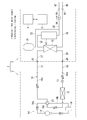
- FIG. 1 is a system configuration diagram of a hot water generator according to an embodiment of the present invention.
- the hot water generator 1 is a heat pump type.
- the hot water generator 1 is an outdoor unit 2 (Outdoor Unit), which is a heat source unit that exchanges heat between outdoor air and a refrigerant, and a water heat exchange unit 3 (Hydro) that exchanges heat between water supplied from the outside of the machine and a refrigerant. Unit), a remote controller 4 as an input device that accepts operations by the user, and a control unit 5 that controls the outdoor unit 2 and the water heat exchange unit 3 based on the operations input to the remote controller 4.
- Outdoor Unit Outdoor Unit
- Hydro water heat exchange unit 3
- a remote controller 4 as an input device that accepts operations by the user
- a control unit 5 that controls the outdoor unit 2 and the water heat exchange unit 3 based on the operations input to the remote controller 4.
- the hot water generator 1 circulates a refrigerant between the outdoor unit 2 and the water heat exchange unit 3, and heats the water by exchanging heat between the refrigerant and water in the water heat exchanger 15 in the water heat exchange unit 3.
- the first temperature for example, 40 degrees Celsius, is supplied to the outside of the machine.
- the hot water at the first temperature circulates through an external heating device (not shown), for example, a floor heating system, and is returned to the water heat exchange unit 3. That is, water circulates between the water heat exchange unit 3 and an external heat radiating device such as a heat radiating device of the heating device.
- the hot water generator 1 may supply hot water having a second temperature, for example, about 70 degrees Celsius, to the outside of the machine by using heat exchange between the refrigerant and water and heating by the backup heater 67 described later in combination. can.
- a second temperature for example, about 70 degrees Celsius
- the maximum temperature is about 55 degrees Celsius.
- the hot water of the second temperature is stored and used in a hot water storage device outside the machine.
- the hot water stored in the hot water storage device is supplied to, for example, a washroom, a kitchen, and a bathroom.
- the outdoor unit 2 is installed outdoors, and the water heat exchange unit 3 is installed indoors.
- the outdoor unit 2 and the water heat exchange unit 3 are connected by crossover pipes 21 and 22 of the refrigerant pipe 16 and a communication line (not shown). As described above, in the hot water generator 1, since the water pipe is not laid outdoors, the water does not freeze in the water pipe at the low temperature in winter.
- At least one remote controller 4 which includes, for example, a remote controller 4 provided in the water heat exchange unit 3 and a remote controller (not shown) installed indoors, for example, on a wall surface.
- the hot water generator 1 includes a freezing circuit 10.
- the freezing circuit 10 heats water into hot water by transferring heat from a low temperature portion to a high temperature portion using outdoor air as a heat source.
- the refrigeration circuit 10 includes a compressor 11, an air heat exchanger 12 as an evaporator, an expansion valve 13, a water heat exchanger 15 as a condenser, a compressor 11, an air heat exchanger 12, and an expansion valve 13. , And a refrigerant pipe 16 that connects the water heat exchanger 15 and allows the refrigerant to flow.
- the refrigeration circuit 10 transfers heat from the air heat exchanger 12 to the water heat exchanger 15 and heats water into hot water in the water heat exchanger 15.
- the refrigeration circuit 10 sends the refrigerant discharged from the compressor 11 to either the air heat exchanger 12 or the water heat exchanger 15, and sends the air heat exchanger 12 or the water heat exchanger 15 to the other. It includes a four-way valve 17 that sends the passed refrigerant to the compressor 11 again, and an accumulator 18 provided in the refrigerant pipe 16 between the four-way valve 17 and the compressor 11.
- the water heat exchanger 15 is housed in the water heat exchange unit 3.
- Other components of the refrigeration circuit 10 are housed in the outdoor unit 2.
- the air heat exchanger 12 functions as an evaporator (also referred to as a “heat absorber”) when the refrigeration circuit 10 heats water, and the water heat exchanger 15 is a condenser (also referred to as a “radiator”). .) Functions.
- the compressor 11 compresses the refrigerant, boosts the pressure, and discharges the refrigerant.
- the operating frequency of the compressor 11 can be changed by known inverter control. Increasing the rotation speed of the compressor 11 increases the amount of heat transferred to the high temperature portion, and decreasing the rotation speed decreases the amount of heat transferred to the high temperature portion. Further, by increasing the rotation speed of the compressor 11, the power consumption of the compressor 11 also increases.
- the expansion valve 13 is, for example, an electronic expansion valve (Pulse Motor Valve, PMV).
- the expansion valve 13 can adjust the valve opening degree.
- the expansion valve 13 includes, for example, a valve body having a through hole, a needle capable of advancing and retreating with respect to the through hole, and a power source for advancing and retreating the needle.
- the expansion valve 13 stops (cuts off) the flow of the refrigerant in the refrigerating circuit 10.
- the expansion valve 13 is in the closed state, and the opening degree of the expansion valve 13 is the smallest.
- the opening degree of the expansion valve 13 is the largest.
- the power source of the expansion valve 13 is, for example, a stepping motor.
- the rotation of the stepping motor causes the needle to move back and forth, changing the distance from the through hole and changing the opening.
- the refrigerant pipe 16 connects the compressor 11, the accumulator 18, the four-way valve 17, the air heat exchanger 12, the expansion valve 13, and the water heat exchanger 15.
- the refrigerant pipe 16 includes a first refrigerant pipe 16a that connects the discharge side of the compressor 11 and the four-way valve 17, a second refrigerant pipe 16b that connects the suction side of the compressor 11 and the four-way valve 17, and the four-way valve 17 and water.
- a third refrigerant pipe 16c connecting the heat exchanger 15, a fourth refrigerant pipe 16d connecting the air heat exchanger 12 and the water heat exchanger 15, and a fifth refrigerant connecting the air heat exchanger 12 and the four-way valve 17. Includes tube 16e and.
- the second refrigerant pipe 16b is provided with an accumulator 18.
- the fourth refrigerant pipe 16d is provided with an expansion valve 13.
- the four-way valve 17 switches the direction of the refrigerant flow in the refrigerant pipe 16.
- the four-way valve 17 allows the refrigerant to flow from the first refrigerant pipe 16a to the third refrigerant pipe 16c, and the refrigerant from the fifth refrigerant pipe 16e to the second refrigerant pipe 16b. (The flow of the refrigerant shown by the solid line in FIG. 1).
- the hot water generator 1 discharges the compressed high-temperature and high-pressure refrigerant from the compressor 11 and sends this refrigerant to the water heat exchanger 15 via the four-way valve 17.
- the water heat exchanger 15 causes heat exchange between the water passing through the water heat exchanger 15 and the refrigerant passing through the water heat exchanger 15. Then, the water is heated, the refrigerant is cooled, and a high-pressure liquid state is obtained. That is, when the water is heated to hot water, the water heat exchanger 15 functions as a radiator.
- the refrigerant that has passed through the water heat exchanger 15 passes through the expansion valve 13 and is depressurized to become a low-pressure gas-liquid two-phase refrigerant that reaches the air heat exchanger 12.
- the air heat exchanger 12 cools the outdoor air by exchanging heat between the outdoor air and the refrigerant passing through the air heat exchanger 12. At this time, the air heat exchanger 12 functions as a heat absorber that evaporates the refrigerant to make it in a gaseous state.
- the refrigerant that has passed through the air heat exchanger 12 is sucked into the compressor 11.
- the refrigerating circuit 10 can be defrosted by switching the direction of the refrigerant flow in the refrigerant pipe 16 by the four-way valve 17.
- the hot water generator 1 inverts the four-way valve 17 to generate a flow of the refrigerant in the refrigerating circuit 10 in the opposite direction to the flow of the refrigerant for heating the water into hot water.
- the four-way valve 17 circulates the refrigerant from the first refrigerant pipe 16a to the fifth refrigerant pipe 16e, and circulates the refrigerant from the third refrigerant pipe 16c to the second refrigerant pipe 16b (FIG. 1). Refrigerant flow shown by broken lines in the middle).
- the air heat exchanger 12 functions as a condenser
- the water heat exchanger 15 functions as an evaporator.
- the refrigeration circuit 10 may be dedicated to heating water without a four-way valve 17.
- the discharge side of the compressor 11 is connected to the water heat exchanger 15 through the refrigerant pipe 16, and the suction side of the compressor 11 is connected to the air heat exchanger 12 through the refrigerant pipe 16.
- the water heat exchange unit 3 guides the water heat exchanger 15 of the refrigeration circuit 10, the expansion tank 31 (Expansion vessel), and the water before being heated to the water heat exchanger 15 from outside the water heat exchange unit 3.
- the water heat exchange unit 3 may be used for circulating hot water between the water heat exchange unit 3 and a device outside the water heat exchange unit 3, or outside the water heat exchange unit 3. It may be used for heating water into hot water and supplying the hot water to the outside of the water heat exchange unit 3.
- the device outside the water heat exchange unit 3 is, for example, a heating device (not shown) or a hot water storage device (not shown) that heats water with circulating hot water and stores the water warmed by the hot water.
- the water heat exchange unit 3 includes a refrigerant pipe connection joint 25, 26 for connecting the cross pipes 21 and 22 of the refrigerant pipe 16 to the refrigerant pipe 16 in the water heat exchange unit 3, and a water pipe outside the water heat exchange unit 3. It includes a water guide pipe connecting joint 46 that connects 45 to the water conducting pipe 32, and a hot water supply pipe connecting joint 48 that connects the hot water pipe 47 outside the water heat exchange unit 3 to the hot water supply pipe 35.
- These connecting joints 25, 26, 46, 48 are screw type pipe joints.
- the crossover pipes 21 and 22 of the refrigerant pipe 16 allow the refrigerant to flow between the outdoor unit 2 and the water heat exchange unit 3.
- the crossover pipe 21 is a part of the third refrigerant pipe 16c and is laid on the outside of the outdoor unit 2 and the outside of the water heat exchange unit 3.
- the crossover pipe 22 is a part of the fourth refrigerant pipe 16d, and is laid outside the outdoor unit 2 and outside the water heat exchange unit 3.
- the portion of the third refrigerant pipe 16c that is provided in the water heat exchange unit 3 and connects the refrigerant pipe connection joint 25 and the water heat exchanger 15 is the refrigerant pipe in the first water heat exchange unit. Call it 27.
- a portion of the fourth refrigerant pipe 16d which is provided in the water heat exchange unit 3 and connects the refrigerant pipe connection joint 26 and the water heat exchanger 15, is a part of the refrigerant pipe in the second water heat exchange unit. Call it 28.
- the hot water pipe 47 is a cross pipe connecting the water heat exchange unit 3 and the hot water supply point
- the water pipe 45 is a cross pipe connecting the water heat exchange unit 3 and the water supply point. In the case of the circulation type, the hot water supply point and the water supply point are connected.
- the hot water guide pipe 33 connects the downstream of the backup heater 67 of the hot water supply pipe 35 and the upstream of the pump 36 to the expansion tank 31.
- the hot water guide pipe 33 guides the warmed and expanded hot water in the hot water supply pipe 35 to the expansion tank 31.
- the expansion tank 31 has a function of absorbing the expansion (increase in volume) of the warmed hot water.
- the hot water heated in the water heat exchanger 15 by the refrigerant circulating in the refrigeration circuit 10 is sucked into the hot water supply pipe 35 by the driving pump 36 and sent to the hot water supply location through the hot water pipe 47 outside the water heat exchange unit 3. ..
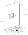
- FIG. 2 is a perspective view of the water heat exchange unit 3 as viewed diagonally from the front and lower right.
- FIG. 3 is an exploded perspective view of the water heat exchange unit 3 as viewed diagonally to the right from above.
- the water heat exchange unit 3 of the hot water generator 1 includes a vertically long rectangular housing 51.
- the housing 51 has a front surface 51f, a back surface 51r, a top surface 51t, a bottom surface 51b, and a pair of side surfaces 51s. Further, the housing 51 includes a front plate 52 that covers the front surface 51f, a back plate 53 that covers the back surface 51r, a top surface plate 54 that covers the top surface 51t, a bottom surface plate 55 that covers the bottom surface 51b, and a pair of sides that cover each side surface 51s.
- the face plates 56 and 57 are provided.
- the housing 51 includes an expansion tank 31, a water guide pipe 32, a hot water guide pipe 33, a hot water supply pipe 35, a pump 36, a water heat exchanger 15 of a refrigeration circuit 10, a refrigerant pipe 27 in a first water heat exchange unit, and a second water. It houses the refrigerant pipe 28 in the heat exchange unit.
- the housing 51 houses a control unit storage box 61 that houses the control unit 5 and a control unit support plate 62 that supports the control unit storage box 61 in the housing 51.
- the control unit storage box 61 is a box body that opens toward the front of the housing 51. A substrate on which the control unit 5 is mounted is supported in the control unit storage box 61.
- the front plate 52 has an operation window 63 on which the remote controller 4 is arranged.
- a controller support plate 65 that supports the remote controller 4 arranged in the operation window 63 is provided.
- the controller support plate 65 has a function of a lid that covers the control unit storage box 61.
- the front plate 52, the back plate 53, the top plate 54, the bottom plate 55, the side plates 56 and 57, the control unit storage box 61, the control unit support plate 62, and the controller support plate 65 are sheet metal processed products.
- the water guide pipe 32, the hot water guide pipe 33, the hot water supply pipe 35, the pump 36, the water heat exchanger 15 of the refrigeration circuit 10, the refrigerant pipe 27 in the first water heat exchange unit, and the refrigerant pipe 28 in the second water heat exchange unit are It is arranged in a space sandwiched between the back plate 53 and the control unit support plate 62.
- the expansion tank 31 is located above the control unit support plate 62 and is arranged in a space sandwiched between the front plate 52 and the back plate 53.
- the back plate 53 of the housing 51 of the hot water generator 1 supports the expansion tank 31 and the water heat exchanger 15 of the freezing circuit 10.
- the expansion tank 31 has a cylindrical shape, and the length dimension L in the center line C direction is larger than the diameter dimension D. Further, the expansion tank 31 is housed in the housing 51 with the center line C facing in the direction of the pair of side surfaces 51s. That is, the length dimension L of the expansion tank 31 is smaller than the width dimension of the housing 51. Further, the diameter dimension D of the expansion tank 31 is smaller than the height dimension and the depth dimension of the housing 51.
- the expansion tank 31 is arranged at the uppermost part in the housing 51.
- the expansion tank 31 includes a cylindrical body portion 31a and a pair of end plates 31b and 31c that close both ends of the body portion 31a.
- the expansion tank 31 is fixed to the back plate 53 by a saddle-shaped tank fixing band 66 straddling the body portion 31a.
- the tank fixing band 66 fixes the expansion tank 31 to the back plate 53 like a saddle band used for fixing the pipe. That is, the tank fixing band 66 straddles the body portion 31a from above to below the body portion 31a and fixes the expansion tank 31 to the back plate 53 of the housing 51.
- the water guide pipe 32, the hot water guide pipe 33, the hot water supply pipe 35, the pump 36, the water heat exchanger 15 of the refrigeration circuit 10, the refrigerant pipe 27 in the first water heat exchange unit, and the refrigerant pipe 28 in the second water heat exchange unit are It is arranged below the expansion tank 31.
- the water heat exchanger 15 is arranged directly below the expansion tank 31 and in the vicinity of the side plate 56 on either the left or right side (the left side in this case) of the housing 51.
- a backup heater 67 is arranged directly below the expansion tank 31 and in the vicinity of the side plate 57 on either the left or right side (right side in this case) of the housing 51.
- the heater 67 is fixed to the back plate 53.
- the heater 67 assists the heating of water in a situation where the outside air temperature is extremely low and it is difficult for the freezing circuit 10 to heat the water into hot water, or the hot water heated by the freezing circuit 10 is heated to a higher temperature hot water. It is used to do.
- the pump 36 is arranged below the expansion tank 31 and directly in front of the heater 67 and on the bottom plate 55 of the housing 51.
- a hot water supply pipe connecting joint 48 is provided directly below the pump 36.
- the hot water supply pipe connection joint 48 projects to the outside of the housing 51.
- the hot water supply pipe connecting joint 48 projects downward from the bottom plate 55 and is exposed to the outside of the housing 51.
- a water pipe connecting joint 46 is provided diagonally to the left of the hot water supply pipe connecting joint 48.
- the water pipe 32 connected to the water pipe connecting joint 46 bends toward the water heat exchanger 15 at a portion that enters the back side of the housing 51 from the bottom plate 55 of the housing 51, and bottoms in the vicinity of the bottom plate 55. It extends parallel to the face plate 55 and is connected to the back side of the lower end portion of the right side surface of the water heat exchanger 15.
- a hot water supply pipe 35 is connected to the back side of the upper end portion of the right side surface of the water heat exchanger 15.
- the hot water supply pipe 35 bends from the water heat exchanger 15 toward the side plate 57 of the housing 51, bends toward the bottom plate 55 of the housing 51 at an intermediate position between the water heat exchanger 15 and the heater 67, and hangs directly below. A portion that reaches the vicinity of the lower end portion of the heater 67 extends parallel to the bottom plate 55 and is connected to the lower end portion of the left side surface of the heater 67.
- the hot water guide pipe 33 branches from the hot water supply pipe 35 through a cross-shaped branch at the upper end of the front surface of the heater 67, rises toward the top plate 54 of the housing 51, and rises toward the top plate 54 of the housing 51, and the center line C of the expansion tank 31. It reaches substantially the same height as the above, and is connected to the end plate 31b on the left side of the expansion tank 31 by bypassing the front surface of the expansion tank 31.
- the hot water supply pipe 35 extends downward from the cross-shaped (cross-shaped) branch and reaches the pump 36. That is, the pump 36 is connected to the outlet end of the hot water supply pipe 35.
- the refrigerant pipe 27 in the first water heat exchange unit and the refrigerant pipe 28 in the second water heat exchange unit enter the housing 51 through the refrigerant pipe insertion hole 71 provided in the bottom plate 55 of the housing 51.
- the refrigerant pipe 27 in the first water heat exchange unit extends on the right side of the water heat exchanger 15 toward the expansion tank 31, and the water heat exchanger 15 is located near the upper end portion of the right side surface of the water heat exchanger 15. It bends toward and is connected to the water heat exchanger 15.
- the refrigerant pipe 27 in the first water heat exchange unit rises and extends substantially directly in front of the hanging portion of the hot water supply pipe 35.
- the refrigerant pipe connecting joint 25 is provided at the end of the refrigerant pipe 27 in the first water heat exchange unit arranged outside the housing 51.
- the refrigerant pipe 28 in the second water heat exchange unit rises closer to the water heat exchanger 15 than the refrigerant pipe 27 in the first water heat exchange unit in parallel with the refrigerant pipe 27 in the first water heat exchange unit to generate water heat. It bends toward the water heat exchanger 15 near the lower end of the right side of the exchanger 15 and is connected to the water heat exchanger 15.
- the refrigerant pipe connecting joint 26 is provided at the end of the refrigerant pipe 28 in the second water heat exchange unit arranged outside the housing 51.
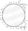
- FIG. 6 is a vertical cross-sectional view of the hot water generator according to the present embodiment.
- the expansion tank 31 of the hot water generator 1 protrudes outward in the radial direction of the cylindrical body portion 31a, and the body portion 31a It is provided with at least one convex portion 81 extending in the circumferential direction of the above.
- the convex portion 81 goes around the body portion 31a in a ring shape and is connected in succession. There are a plurality of convex portions 81, and the first convex portion 81a and the second convex portion 81b are included.
- the convex portion 81 is, for example, a joint portion that joins two members to form an integral body portion 31a, or a holding portion that holds a diaphragm (not shown) in the expansion tank 31 on the inner peripheral surface of the body portion 31a. Or something like that.
- the plurality of convex portions 81a and 81b are separated from each other in the direction of the center line of the expansion tank 31 and are arranged in parallel.
- the convex portion 81 may be provided on the body portion 31a in an annular and discrete manner (jumping, discontinuous).
- the tank fixing band 66 may be a hexagonal saddle shape shown in FIGS. 4 to 6, a polygonal saddle shape such as a triangle, a rectangle, or a pentagon, or an arc-shaped saddle shape. It may be in shape.
- the hexagonal saddle-shaped tank fixing band 66 expands while being connected to the first portion 66a, which is in contact with the top of the expansion tank 31 and fixed to the back plate 53, and the first portion 66a, which is partially in contact with the expansion tank 31.
- a second portion 66b that is inclined downward toward the front of the tank 31, a third portion 66c that is connected to the second portion 66b and is partially in contact with the expansion tank 31, and is located in front of the expansion tank 31.
- the fourth part 66d which is connected to the part 66c and is partially in contact with the expansion tank 31, and is inclined downward toward the bottom of the expansion tank 31, and the back plate, which is connected to the fourth part 66d and is in contact with the bottom of the expansion tank 31. It has a fifth portion 66e, which is fixed to 53, and a fifth portion 66e.
- the tank fixing band 66 has at least one hole 82 for fitting the convex portion 81.
- the hole 82 is provided at a position where the convex portion 81 can be fitted from one end of the tank fixing band 66 toward the other end.
- the hole portions 82 are arranged in a plurality of rows and include a first hole portion 82a into which the first convex portion 81a is fitted and a second hole portion 82b into which the second convex portion 81b is fitted.
- the plurality of holes 82a and 82b are separated from each other in the band width direction of the tank fixing band 66 and are arranged in parallel.
- the holes 82 are preferably provided discretely (jumped, discontinuous) while avoiding vertices as shown in FIGS. 4 to 6. .. In this case, the tank fixing band 66 can easily obtain the strength capable of supporting the expansion tank 31.
- the holes 82 are discretely provided from the first part 66a to the fifth part 66e of the tank fixing band 66, and are interrupted at the apex connecting the respective parts.
- the back plate 53 includes a band fixing hole 85 provided above the expansion tank 31, a band fastening hole 86 provided below the expansion tank 31, and a pair of rolling that prevents the expansion tank 31 from rolling with respect to the back plate 53. It is equipped with a stop 87.
- the band fastening hole 86 is provided in the flange portion 53a for fixing the top plate 54 to the back plate 53.
- the pair of roll stoppers 87 have a convex shape that is below the band fixing hole 85 and above the band fastening hole 86 and extends parallel to the longitudinal direction of the expansion tank 31.
- the expansion tank 31 is in contact with the back plate 53 at a portion sandwiched between the pair of rolling stoppers 87.
- the expansion tank 31 is also preferably in contact with the pair of rolling stoppers 87.
- the tank fixing band 66 includes a folded-back portion 66f that is inserted into the band fixing hole 85 of the back plate 53, and a flange portion 66g that is fixed to the band fastening hole 86 by the fastening member 89.
- the folded-back portion 66f is provided at the upper end portion of the tank fixing band 66, that is, at the root portion of the first portion 66a.
- the folded-back portion 66f is a cut-up formed by bending a plate material of a material on a tank fixing band 66 which is a processed sheet metal product.
- the flange portion 66g is provided at the lower end portion of the tank fixing band 66, that is, at the root portion of the fifth portion 66e.
- a fastening member is used in addition to or in place of the folded-back portion 66f to fix the root portion of the first portion 66a of the tank fixing band 66 having the folded-back portion 66f to the flange portion 53a of the back plate 53. Is also good.
- the depth dimension of the housing 51 depends on the diameter dimension D of the expansion tank 31, even if the expansion tank 31 is erected and housed in the housing 51, the expansion tank 31 is laid down and housed in the housing 51. However, it does not change substantially.
- the width dimension of the housing 51 depends on the size and arrangement of devices other than the expansion tank 31 in the housing 51, when the expansion tank 31 is erected and housed in the housing 51, any device is contained in the housing 51. A large-capacity space, so-called dead space, is created. When the expansion tank 31 is laid down and housed in the housing 51, the width dimension of the housing 51 can be effectively utilized as shown in FIG.
- the expansion tank 31 by laying down the expansion tank 31 and accommodating it in the housing 51, the height dimension of the housing 51 can be suppressed and the water heat exchange unit 3 can be miniaturized. Further, by laying the expansion tank 31 on its side and accommodating it in the housing 51, the length dimension L of the expansion tank 31 is extended within the range within the width dimension of the housing 51, and the internal volume of the expansion tank 31 is expanded. ..
- the hot water generator 1 has a cylindrical shape, the length dimension L in the center line C direction is larger than the diameter dimension D, and the center line C is a pair of side surfaces of the housing 51.
- An expansion tank 31 housed in the housing 51 is provided in the direction of 51s. Therefore, the hot water generator 1 can accommodate the cylindrical expansion tank 31 which is cheaper and lighter than the rectangular tank having the same internal volume, and can efficiently utilize the space inside the housing 51. can.
- the water heat exchange unit 3 of the hot water generator 1 can have a good appearance, which is small and lightweight, has high workability at the time of installation, and occupies a small space in the installed state.
- the hot water generator 1 includes an expansion tank 31 arranged at the uppermost part in the housing 51. Therefore, the hot water generation device 1 can reduce the size of the water heat exchange unit 3 and efficiently allocate the arrangement of the expansion tank 31 and the devices other than the expansion tank 31 housed in the housing 51.
- the hot water generator 1 has a hole 82 for fitting the convex portion 81 of the expansion tank 31, and straddles the body portion 31a of the expansion tank 31 from above to below.
- a tank fixing band 66 for fixing the expansion tank 31 to the back plate 53 of the housing 51 is provided. Therefore, the hot water generator 1 can securely fix the expansion tank 31 at a predetermined position and prevent the installation position of the expansion tank 31 from shifting.
- a pair of roll stoppers 87 that prevent the expansion tank 31 from rolling with respect to the back plate 53, a folded-back portion 66f that is inserted into the band fixing hole 85 of the back plate 53, and a folded portion 66f. It includes a tank fixing band 66 having a flange portion 66 g fixed to the band fastening hole 86 of the back plate 53 by the fastening member 89. Therefore, the hot water generator 1 can easily fix the expansion tank 31 to the back plate 53, and can firmly fix the expansion tank 31 to the back plate 53.
- the cylindrical expansion tank 31 can be efficiently housed in the rectangular housing 51.
Landscapes
- Engineering & Computer Science (AREA)
- Physics & Mathematics (AREA)
- Thermal Sciences (AREA)
- Chemical & Material Sciences (AREA)
- Combustion & Propulsion (AREA)
- Mechanical Engineering (AREA)
- General Engineering & Computer Science (AREA)
- Heat-Pump Type And Storage Water Heaters (AREA)
- Percussion Or Vibration Massage (AREA)
- Thermotherapy And Cooling Therapy Devices (AREA)
- Devices For Medical Bathing And Washing (AREA)
- Details Of Fluid Heaters (AREA)
Abstract
Description
Claims (4)
- 内部に圧縮機と、冷媒と空気とを熱交換する熱交換器と、を有する室外ユニットと、
前記室外ユニットから流入する前記冷媒と水とを熱交換する水熱交換器を有する水熱交換ユニットと、を備え、
前記水熱交換ユニットは、
正面、背面、天面、底面、および一対の側面を有する矩形の筐体と、
円筒形状であって中心線方向における長さ寸法が直径寸法よりも大きく、かつ中心線を前記一対の側面の方向へ向けて前記筐体に収容される膨張タンクと、を備える温水生成装置。 - 前記膨張タンクは、前記筐体内の最上部に配置されている請求項1に記載の温水生成装置。
- 前記膨張タンクは、円筒形状の胴部と、前記胴部の径方向外側へ向かって突出し、かつ前記胴部の周方向へ延びる凸部と、を有し、
前記凸部を嵌合させる孔を有し、かつ前記胴部を前記胴部の上方から下方へ跨いで前記膨張タンクを前記筐体の背面板に固定する固定帯を備える請求項1または2に記載の温水生成装置。 - 前記背面板は、前記膨張タンクより上方に設けられるバンド固定孔と、前記膨張タンクより下方に設けられるバンド締結穴と、前記膨張タンクが前記背面板に対して転がることを妨げる一対の転がり止めと、を有し、
前記固定帯は、前記バンド固定孔に差し込まれる折返し部と、締結部材によって前記バンド締結穴に固定されるフランジ部と、を有する請求項3に記載の温水生成装置。
Priority Applications (4)
| Application Number | Priority Date | Filing Date | Title |
|---|---|---|---|
| NZ792392A NZ792392B2 (en) | 2020-03-23 | Hot water generator | |
| PCT/JP2020/012672 WO2021191959A1 (ja) | 2020-03-23 | 2020-03-23 | 温水生成装置 |
| EP20926468.8A EP4130600B1 (en) | 2020-03-23 | 2020-03-23 | Hot water generating device |
| AU2020438508A AU2020438508B9 (en) | 2020-03-23 | 2020-03-23 | Hot water generating device |
Applications Claiming Priority (1)
| Application Number | Priority Date | Filing Date | Title |
|---|---|---|---|
| PCT/JP2020/012672 WO2021191959A1 (ja) | 2020-03-23 | 2020-03-23 | 温水生成装置 |
Publications (1)
| Publication Number | Publication Date |
|---|---|
| WO2021191959A1 true WO2021191959A1 (ja) | 2021-09-30 |
Family
ID=77889978
Family Applications (1)
| Application Number | Title | Priority Date | Filing Date |
|---|---|---|---|
| PCT/JP2020/012672 Ceased WO2021191959A1 (ja) | 2020-03-23 | 2020-03-23 | 温水生成装置 |
Country Status (3)
| Country | Link |
|---|---|
| EP (1) | EP4130600B1 (ja) |
| AU (1) | AU2020438508B9 (ja) |
| WO (1) | WO2021191959A1 (ja) |
Cited By (2)
| Publication number | Priority date | Publication date | Assignee | Title |
|---|---|---|---|---|
| WO2024228227A1 (ja) * | 2023-05-01 | 2024-11-07 | 三菱電機株式会社 | 給湯機 |
| WO2025001995A1 (zh) * | 2023-06-30 | 2025-01-02 | 广东美的暖通设备有限公司 | 一种水力模块及热泵系统 |
Citations (6)
| Publication number | Priority date | Publication date | Assignee | Title |
|---|---|---|---|---|
| JPS50134056U (ja) * | 1974-04-18 | 1975-11-05 | ||
| WO2007142144A1 (ja) | 2006-06-02 | 2007-12-13 | Toshiba Carrier Corporation | ヒートポンプ給湯システム |
| JP2015161424A (ja) * | 2014-02-26 | 2015-09-07 | 株式会社富士通ゼネラル | 温水暖房装置 |
| JP2016188732A (ja) * | 2015-03-30 | 2016-11-04 | 株式会社長府製作所 | 膨張タンク |
| JP2017067373A (ja) * | 2015-09-30 | 2017-04-06 | ダイキン工業株式会社 | 水熱交換器収容ユニット |
| US20170276405A1 (en) * | 2016-02-05 | 2017-09-28 | James T. Bober | Apparatus for supporting expansion tank |
Family Cites Families (5)
| Publication number | Priority date | Publication date | Assignee | Title |
|---|---|---|---|---|
| GB1370458A (en) * | 1970-10-08 | 1974-10-16 | Junkers & Co | Gas-fired circulation water heater |
| KR101329509B1 (ko) * | 2008-08-04 | 2013-11-13 | 엘지전자 주식회사 | 히트펌프 연동 온수 순환 시스템 및 제어 방법 |
| JP6720492B2 (ja) * | 2015-09-30 | 2020-07-08 | ダイキン工業株式会社 | 水熱交換器収容ユニット |
| JP6623649B2 (ja) * | 2015-09-30 | 2019-12-25 | ダイキン工業株式会社 | 水熱交換器収容ユニット |
| US10429097B1 (en) * | 2017-02-27 | 2019-10-01 | Rex A. Sexton | Expansion tank wall mount bracket apparatus and method of use |
-
2020
- 2020-03-23 EP EP20926468.8A patent/EP4130600B1/en active Active
- 2020-03-23 AU AU2020438508A patent/AU2020438508B9/en active Active
- 2020-03-23 WO PCT/JP2020/012672 patent/WO2021191959A1/ja not_active Ceased
Patent Citations (6)
| Publication number | Priority date | Publication date | Assignee | Title |
|---|---|---|---|---|
| JPS50134056U (ja) * | 1974-04-18 | 1975-11-05 | ||
| WO2007142144A1 (ja) | 2006-06-02 | 2007-12-13 | Toshiba Carrier Corporation | ヒートポンプ給湯システム |
| JP2015161424A (ja) * | 2014-02-26 | 2015-09-07 | 株式会社富士通ゼネラル | 温水暖房装置 |
| JP2016188732A (ja) * | 2015-03-30 | 2016-11-04 | 株式会社長府製作所 | 膨張タンク |
| JP2017067373A (ja) * | 2015-09-30 | 2017-04-06 | ダイキン工業株式会社 | 水熱交換器収容ユニット |
| US20170276405A1 (en) * | 2016-02-05 | 2017-09-28 | James T. Bober | Apparatus for supporting expansion tank |
Non-Patent Citations (1)
| Title |
|---|
| See also references of EP4130600A4 |
Cited By (3)
| Publication number | Priority date | Publication date | Assignee | Title |
|---|---|---|---|---|
| WO2024228227A1 (ja) * | 2023-05-01 | 2024-11-07 | 三菱電機株式会社 | 給湯機 |
| GB2642898A (en) * | 2023-05-01 | 2026-01-28 | Mitsubishi Electric Corp | Water heater |
| WO2025001995A1 (zh) * | 2023-06-30 | 2025-01-02 | 广东美的暖通设备有限公司 | 一种水力模块及热泵系统 |
Also Published As
| Publication number | Publication date |
|---|---|
| NZ792392A (en) | 2025-05-30 |
| EP4130600A4 (en) | 2023-12-13 |
| EP4130600B1 (en) | 2025-04-30 |
| EP4130600A1 (en) | 2023-02-08 |
| AU2020438508A1 (en) | 2022-10-13 |
| AU2020438508B9 (en) | 2024-01-11 |
| AU2020438508B2 (en) | 2023-12-21 |
Similar Documents
| Publication | Publication Date | Title |
|---|---|---|
| US20160231008A1 (en) | Heat radiation unit and outdoor unit of air conditioner having the same | |
| JP6156323B2 (ja) | 熱交換器組立体および冷凍装置の室外ユニット | |
| JP5838788B2 (ja) | ヒートポンプ給湯装置 | |
| JP5761857B2 (ja) | 二元冷凍サイクル装置 | |
| WO2021191959A1 (ja) | 温水生成装置 | |
| EP3124890B1 (en) | Heat-generating unit | |
| JP5202726B2 (ja) | 負荷側中継ユニット及びそれを搭載した空調給湯複合システム | |
| WO2018110103A1 (ja) | 圧縮機ユニット及びこれを備えた室外機 | |
| JP7418551B2 (ja) | 熱交換器、室外機、および空気調和装置 | |
| CN115103984B (zh) | 温水生成装置 | |
| US9702622B2 (en) | Turbo chiller and chiller system including the same | |
| US11231184B2 (en) | Outdoor unit of gas heat pump system | |
| WO2021149222A1 (ja) | 冷凍サイクル装置の室外機 | |
| EP4592613A1 (en) | Hot water supply tank, hot water supply tank unit, and heat-pump water heater | |
| WO2024111100A1 (ja) | 給湯タンクユニット、およびヒートポンプ温水器 | |
| JP2016038133A (ja) | 流体容器の支持構造 | |
| JP2016011772A (ja) | 空気調和装置の床置式室内ユニット | |
| US11674732B2 (en) | Refrigerator | |
| KR20150080833A (ko) | 공기조화기의 실외기 | |
| JP7327630B2 (ja) | ヒートポンプ装置及び貯湯式給湯機 | |
| EP3799615B1 (en) | Refrigerator | |
| JP2019049402A (ja) | 室外ユニット及びそれを備えた冷凍装置 | |
| JP2022116685A (ja) | 冷凍装置 | |
| JP2010230180A (ja) | ヒートポンプ給湯機 | |
| JP2019158305A (ja) | 輻射パネル及び空気調和装置 |
Legal Events
| Date | Code | Title | Description |
|---|---|---|---|
| 121 | Ep: the epo has been informed by wipo that ep was designated in this application |
Ref document number: 20926468 Country of ref document: EP Kind code of ref document: A1 |
|
| ENP | Entry into the national phase |
Ref document number: 2020438508 Country of ref document: AU Date of ref document: 20200323 Kind code of ref document: A |
|
| NENP | Non-entry into the national phase |
Ref country code: DE |
|
| ENP | Entry into the national phase |
Ref document number: 2020926468 Country of ref document: EP Effective date: 20221024 |
|
| NENP | Non-entry into the national phase |
Ref country code: JP |
|
| WWG | Wipo information: grant in national office |
Ref document number: 2020926468 Country of ref document: EP |
|
| WWG | Wipo information: grant in national office |
Ref document number: 792392 Country of ref document: NZ |