WO2021192156A1 - 燃料製造装置 - Google Patents
燃料製造装置 Download PDFInfo
- Publication number
- WO2021192156A1 WO2021192156A1 PCT/JP2020/013721 JP2020013721W WO2021192156A1 WO 2021192156 A1 WO2021192156 A1 WO 2021192156A1 JP 2020013721 W JP2020013721 W JP 2020013721W WO 2021192156 A1 WO2021192156 A1 WO 2021192156A1
- Authority
- WO
- WIPO (PCT)
- Prior art keywords
- reactor
- hydrogen
- internal combustion
- combustion engine
- fuel
- Prior art date
- Legal status (The legal status is an assumption and is not a legal conclusion. Google has not performed a legal analysis and makes no representation as to the accuracy of the status listed.)
- Ceased
Links
Images




Classifications
-
- F—MECHANICAL ENGINEERING; LIGHTING; HEATING; WEAPONS; BLASTING
- F01—MACHINES OR ENGINES IN GENERAL; ENGINE PLANTS IN GENERAL; STEAM ENGINES
- F01N—GAS-FLOW SILENCERS OR EXHAUST APPARATUS FOR MACHINES OR ENGINES IN GENERAL; GAS-FLOW SILENCERS OR EXHAUST APPARATUS FOR INTERNAL-COMBUSTION ENGINES
- F01N3/00—Exhaust or silencing apparatus having means for purifying, rendering innocuous, or otherwise treating exhaust
- F01N3/005—Exhaust or silencing apparatus having means for purifying, rendering innocuous, or otherwise treating exhaust for draining or otherwise eliminating condensates or moisture accumulating in the apparatus
-
- F—MECHANICAL ENGINEERING; LIGHTING; HEATING; WEAPONS; BLASTING
- F02—COMBUSTION ENGINES; HOT-GAS OR COMBUSTION-PRODUCT ENGINE PLANTS
- F02M—SUPPLYING COMBUSTION ENGINES IN GENERAL WITH COMBUSTIBLE MIXTURES OR CONSTITUENTS THEREOF
- F02M25/00—Engine-pertinent apparatus for adding non-fuel substances or small quantities of secondary fuel to combustion-air, main fuel or fuel-air mixture
- F02M25/10—Engine-pertinent apparatus for adding non-fuel substances or small quantities of secondary fuel to combustion-air, main fuel or fuel-air mixture adding acetylene, non-waterborne hydrogen, non-airborne oxygen, or ozone
- F02M25/12—Engine-pertinent apparatus for adding non-fuel substances or small quantities of secondary fuel to combustion-air, main fuel or fuel-air mixture adding acetylene, non-waterborne hydrogen, non-airborne oxygen, or ozone the apparatus having means for generating such gases
-
- C—CHEMISTRY; METALLURGY
- C01—INORGANIC CHEMISTRY
- C01B—NON-METALLIC ELEMENTS; COMPOUNDS THEREOF; METALLOIDS OR COMPOUNDS THEREOF NOT COVERED BY SUBCLASS C01C
- C01B3/00—Hydrogen; Gaseous mixtures containing hydrogen; Separation of hydrogen from mixtures containing it; Purification of hydrogen; Reversible storage of hydrogen
- C01B3/0005—Reversible storage of hydrogen, e.g. by hydrogen getters or electrodes
- C01B3/001—Reversible storage of hydrogen, e.g. by hydrogen getters or electrodes characterised by the uptaking media; Treatment thereof
- C01B3/0015—Organic compounds, e.g. liquid organic hydrogen carriers [LOHC] or metalorganic compounds; Solutions thereof
-
- C—CHEMISTRY; METALLURGY
- C10—PETROLEUM, GAS OR COKE INDUSTRIES; TECHNICAL GASES CONTAINING CARBON MONOXIDE; FUELS; LUBRICANTS; PEAT
- C10L—FUELS NOT OTHERWISE PROVIDED FOR; NATURAL GAS; SYNTHETIC NATURAL GAS OBTAINED BY PROCESSES NOT COVERED BY SUBCLASSES C10G OR C10K; LIQUIFIED PETROLEUM GAS; USE OF ADDITIVES TO FUELS OR FIRES; FIRE-LIGHTERS
- C10L3/00—Gaseous fuels; Natural gas; Synthetic natural gas obtained by processes not covered by subclass C10G, C10K; Liquefied petroleum gas
- C10L3/06—Natural gas; Synthetic natural gas obtained by processes not covered by C10G, C10K3/02 or C10K3/04
- C10L3/08—Production of synthetic natural gas
-
- C—CHEMISTRY; METALLURGY
- C25—ELECTROLYTIC OR ELECTROPHORETIC PROCESSES; APPARATUS THEREFOR
- C25B—ELECTROLYTIC OR ELECTROPHORETIC PROCESSES FOR THE PRODUCTION OF COMPOUNDS OR NON-METALS; APPARATUS THEREFOR
- C25B15/00—Operating or servicing cells
- C25B15/08—Supplying or removing reactants or electrolytes; Regeneration of electrolytes
- C25B15/081—Supplying products to non-electrochemical reactors that are combined with the electrochemical cell, e.g. Sabatier reactor
-
- F—MECHANICAL ENGINEERING; LIGHTING; HEATING; WEAPONS; BLASTING
- F01—MACHINES OR ENGINES IN GENERAL; ENGINE PLANTS IN GENERAL; STEAM ENGINES
- F01N—GAS-FLOW SILENCERS OR EXHAUST APPARATUS FOR MACHINES OR ENGINES IN GENERAL; GAS-FLOW SILENCERS OR EXHAUST APPARATUS FOR INTERNAL-COMBUSTION ENGINES
- F01N3/00—Exhaust or silencing apparatus having means for purifying, rendering innocuous, or otherwise treating exhaust
- F01N3/08—Exhaust or silencing apparatus having means for purifying, rendering innocuous, or otherwise treating exhaust for rendering innocuous
-
- F—MECHANICAL ENGINEERING; LIGHTING; HEATING; WEAPONS; BLASTING
- F01—MACHINES OR ENGINES IN GENERAL; ENGINE PLANTS IN GENERAL; STEAM ENGINES
- F01N—GAS-FLOW SILENCERS OR EXHAUST APPARATUS FOR MACHINES OR ENGINES IN GENERAL; GAS-FLOW SILENCERS OR EXHAUST APPARATUS FOR INTERNAL-COMBUSTION ENGINES
- F01N5/00—Exhaust or silencing apparatus combined or associated with devices profiting by exhaust energy
- F01N5/02—Exhaust or silencing apparatus combined or associated with devices profiting by exhaust energy the devices using heat
-
- F—MECHANICAL ENGINEERING; LIGHTING; HEATING; WEAPONS; BLASTING
- F02—COMBUSTION ENGINES; HOT-GAS OR COMBUSTION-PRODUCT ENGINE PLANTS
- F02M—SUPPLYING COMBUSTION ENGINES IN GENERAL WITH COMBUSTIBLE MIXTURES OR CONSTITUENTS THEREOF
- F02M27/00—Apparatus for treating combustion-air, fuel, or fuel-air mixture, by catalysts, electric means, magnetism, rays, sound waves, or the like
- F02M27/04—Apparatus for treating combustion-air, fuel, or fuel-air mixture, by catalysts, electric means, magnetism, rays, sound waves, or the like by electric means, ionisation, polarisation or magnetism
-
- F—MECHANICAL ENGINEERING; LIGHTING; HEATING; WEAPONS; BLASTING
- F02—COMBUSTION ENGINES; HOT-GAS OR COMBUSTION-PRODUCT ENGINE PLANTS
- F02M—SUPPLYING COMBUSTION ENGINES IN GENERAL WITH COMBUSTIBLE MIXTURES OR CONSTITUENTS THEREOF
- F02M31/00—Apparatus for thermally treating combustion-air, fuel, or fuel-air mixture
- F02M31/20—Apparatus for thermally treating combustion-air, fuel, or fuel-air mixture for cooling
-
- C—CHEMISTRY; METALLURGY
- C10—PETROLEUM, GAS OR COKE INDUSTRIES; TECHNICAL GASES CONTAINING CARBON MONOXIDE; FUELS; LUBRICANTS; PEAT
- C10L—FUELS NOT OTHERWISE PROVIDED FOR; NATURAL GAS; SYNTHETIC NATURAL GAS OBTAINED BY PROCESSES NOT COVERED BY SUBCLASSES C10G OR C10K; LIQUIFIED PETROLEUM GAS; USE OF ADDITIVES TO FUELS OR FIRES; FIRE-LIGHTERS
- C10L2290/00—Fuel preparation or upgrading, processes or apparatus therefore, comprising specific process steps or apparatus units
- C10L2290/56—Specific details of the apparatus for preparation or upgrading of a fuel
- C10L2290/567—Mobile or displaceable apparatus
-
- C—CHEMISTRY; METALLURGY
- C25—ELECTROLYTIC OR ELECTROPHORETIC PROCESSES; APPARATUS THEREFOR
- C25B—ELECTROLYTIC OR ELECTROPHORETIC PROCESSES FOR THE PRODUCTION OF COMPOUNDS OR NON-METALS; APPARATUS THEREFOR
- C25B1/00—Electrolytic production of inorganic compounds or non-metals
- C25B1/01—Products
- C25B1/02—Hydrogen or oxygen
- C25B1/04—Hydrogen or oxygen by electrolysis of water
- C25B1/042—Hydrogen or oxygen by electrolysis of water by electrolysis of steam
-
- F—MECHANICAL ENGINEERING; LIGHTING; HEATING; WEAPONS; BLASTING
- F01—MACHINES OR ENGINES IN GENERAL; ENGINE PLANTS IN GENERAL; STEAM ENGINES
- F01N—GAS-FLOW SILENCERS OR EXHAUST APPARATUS FOR MACHINES OR ENGINES IN GENERAL; GAS-FLOW SILENCERS OR EXHAUST APPARATUS FOR INTERNAL-COMBUSTION ENGINES
- F01N2240/00—Combination or association of two or more different exhaust treating devices, or of at least one such device with an auxiliary device, not covered by indexing codes F01N2230/00 or F01N2250/00, one of the devices being
- F01N2240/34—Combination or association of two or more different exhaust treating devices, or of at least one such device with an auxiliary device, not covered by indexing codes F01N2230/00 or F01N2250/00, one of the devices being an electrolyser
-
- Y—GENERAL TAGGING OF NEW TECHNOLOGICAL DEVELOPMENTS; GENERAL TAGGING OF CROSS-SECTIONAL TECHNOLOGIES SPANNING OVER SEVERAL SECTIONS OF THE IPC; TECHNICAL SUBJECTS COVERED BY FORMER USPC CROSS-REFERENCE ART COLLECTIONS [XRACs] AND DIGESTS
- Y02—TECHNOLOGIES OR APPLICATIONS FOR MITIGATION OR ADAPTATION AGAINST CLIMATE CHANGE
- Y02E—REDUCTION OF GREENHOUSE GAS [GHG] EMISSIONS, RELATED TO ENERGY GENERATION, TRANSMISSION OR DISTRIBUTION
- Y02E60/00—Enabling technologies; Technologies with a potential or indirect contribution to GHG emissions mitigation
- Y02E60/30—Hydrogen technology
- Y02E60/36—Hydrogen production from non-carbon containing sources, e.g. by water electrolysis
-
- Y—GENERAL TAGGING OF NEW TECHNOLOGICAL DEVELOPMENTS; GENERAL TAGGING OF CROSS-SECTIONAL TECHNOLOGIES SPANNING OVER SEVERAL SECTIONS OF THE IPC; TECHNICAL SUBJECTS COVERED BY FORMER USPC CROSS-REFERENCE ART COLLECTIONS [XRACs] AND DIGESTS
- Y02—TECHNOLOGIES OR APPLICATIONS FOR MITIGATION OR ADAPTATION AGAINST CLIMATE CHANGE
- Y02P—CLIMATE CHANGE MITIGATION TECHNOLOGIES IN THE PRODUCTION OR PROCESSING OF GOODS
- Y02P20/00—Technologies relating to chemical industry
- Y02P20/10—Process efficiency
- Y02P20/133—Renewable energy sources, e.g. sunlight
Definitions
- the present invention relates to a fuel manufacturing apparatus.
- Patent Document 1 describes a method for producing a hydrocarbon or a hydrocarbon derivative from an electric energy source, wherein a. Steps to provide an electrical energy source, b. The steps of electrolyzing water to produce hydrogen and oxygen using the electrical energy from the electrical energy source, and c. A method including a step of hydrogenating carbon dioxide to produce methane using the generated hydrogen is described, and in the method, a renewable energy source is used as an electric energy source.
- the present inventors decompose high-temperature water vapor contained in the exhaust gas discharged from the internal combustion engine into hydrogen and oxygen by an electrolyzer and decompose them.
- fuel can be produced by efficiently utilizing the energy from an internal combustion engine by converting the hydrogen from a high temperature state into a fuel, and completed the present invention.
- the present invention includes an internal combustion engine, an electrolyzer connected to the internal combustion engine, and a hydrogenation reactor connected to the electric decomposition apparatus, and the electrolysis apparatus is contained in the exhaust gas from the internal combustion engine. It is a device for decomposing high-temperature water vapor contained in hydrogen and oxygen, and is characterized by a fuel production device which is a device for converting the decomposed hydrogen into fuel by a hydrogenation reactor.
- an apparatus for producing fuel using high-temperature exhaust gas emitted from an internal combustion engine there is provided an apparatus for producing fuel using high-temperature exhaust gas emitted from an internal combustion engine. Issues, configurations and effects other than those described above will be clarified by the description of the following embodiments.
- the present invention includes an internal combustion engine, an electrolyzer connected to the internal combustion engine, and a hydrogenation reactor connected to the electric decomposition apparatus, and the electrolyzer is included in the exhaust gas from the internal combustion engine.
- the present invention relates to a fuel production device which is a device for decomposing high-temperature water vapor into hydrogen and oxygen, and is a device for converting the decomposed hydrogen into fuel by a hydrogenation reactor.
- the internal combustion engine in the present invention refers to an engine in which the combustion gas is a working fluid, and includes a reciprocating engine, a rotary engine, and the like.
- the internal combustion engine in the fuel production apparatus of the present invention can be started and / or stopped quickly, and is derived from the renewable energy source when the renewable energy source is used as the electric power used for electrolysis in the electrolyzer. It is possible to easily follow the fluctuating surplus power. Further, the internal combustion engine in the fuel production apparatus of the present invention can shorten the warm-up operation time of the fuel production apparatus.
- bioethanol or hydrous ethanol can be used as an auxiliary fuel.
- bioethanol as an auxiliary fuel in an internal combustion engine, it is possible to suppress the emission of carbon dioxide, which is one of the causes of global warming.
- Combustion in an internal combustion engine is carried out at a temperature known in the art, usually 300 ° C. to 900 ° C., preferably 500 ° C. to 700 ° C.
- the external device for example, the generator can be operated by the mechanical power of the internal combustion engine.
- the temperature of the exhaust gas discharged from the internal combustion engine is usually 250 ° C. to 850 ° C., preferably 350 ° C. to 650 ° C., for example, 350 ° C. to 550 ° C., and the temperature is the electrolysis apparatus described below. Since it corresponds to the temperature of electrolysis, the water vapor contained in the exhaust gas is efficiently decomposed into hydrogen in the electrolysis apparatus as described below.
- the internal combustion engine is operated after being adjusted (adjusted) so that the air-fuel ratio (Air / Fuel ratio) becomes the stoichiometric ratio combustion (stoichiometric combustion: hereinafter referred to as stoichiometric combustion) which is the stoichiometric air-fuel ratio. Is preferable.
- the exhaust gas that will be supplied to the electrolyzer may contain oxygen (O 2).
- oxygen oxygen
- the electrolysis of water vapor in the electrolyzer can be suppressed.
- the exhaust gas discharged from the internal combustion engine does not contain oxygen, and the electricity of the water vapor in the electrolyzer to which the exhaust gas is supplied becomes electric. It is possible to prevent a decrease in decomposition efficiency and consumption of generated hydrogen.
- a spark ignition engine suitable for operation in stoichiometric combustion is desirable for the internal combustion engine in the present invention.
- the internal combustion engine is connected to the electrolyzer, and the exhaust gas discharged from the internal combustion engine is supplied to the electrolyzer.
- the electrolyzer in the present invention is referred to as high temperature electrolysis or steam electrolysis performed at a high temperature with respect to room temperature, for example, usually 250 ° C. to 850 ° C., preferably 350 ° C. to 650 ° C., for example 350 ° C. to 550 ° C. It is a device for performing electrolysis.
- the exhaust gas discharged from the internal combustion engine is at a temperature within the range in which the electrolyzer is operated, and by performing electrolysis in the electrolyzer at the temperature, water vapor is electrolyzed with high efficiency. And can generate hydrogen.
- the water vapor contained in the exhaust gas supplied to the cathode receives electrons and is decomposed into hydrogen and oxygen ions (O 2- ), and the oxygen ions generated at the cathode are between the cathode and the anode. It moves to the anode through the electrolyte located in and produces oxygen at the anode.
- the electrolyzer may include a solid oxide electrolyte as the electrolyte.
- the solid oxide electrolyte for example, yttria-stabilized zirconia ( "YSZ", Y 2 O 3 added ZrO 2) and the like.
- the electrolyzer contains an airtight solid oxide electrolyte, oxygen ions are well conducted at high temperatures, and the separation of hydrogen and oxygen ions can be further promoted.
- the electrolyzer includes an electrode known in the art as an electrode, and for example, a nickel cermet steam / hydrogen electrode may be used.
- renewable energy sources include one or more energies selected from wind energy, tidal energy, wave energy, hydraulic energy, geothermal energy, and solar energy.
- the fuel production apparatus of the present invention may further include an apparatus for decomposing and / or removing harmful substances other than water vapor between the internal combustion engine and the electrolyzer.
- the fuel production apparatus of the present invention further includes an exhaust gas purification catalyst such as a three-way catalyst between the internal combustion engine and the electrolysis apparatus.
- the fuel production apparatus of the present invention further contains an exhaust gas purification catalyst, harmful substances in the exhaust gas discharged from the internal combustion engine are efficiently decomposed and / or removed, and the exhaust gas is supplied. Deterioration and / or corrosion due to harmful substances can be prevented.
- oxygen generated by the electrolyzer may be supplied to the internal combustion engine for combustion of the internal combustion engine.
- the combustion efficiency of the internal combustion engine can be improved.
- the electrolyzer is connected to the hydrogenation reactor, and the hydrogen generated by the electrolyzer is supplied to the hydrogenation reactor.
- a hydrogenation reactor is a device for converting hydrogen generated in an electrolysis device into a fuel with high operability.
- a metanation reactor that reacts hydrogen with carbon dioxide to generate methane, or hydrogen and hydrogen.
- examples thereof include an organic hydride reactor that reacts toluene to produce methylcyclohexane (MCH).
- the methanation reaction is also called the Sabatier reaction, and this reaction is known in the art.
- a temperature of 200 ° C. to 300 ° C. for example, 200 ° C. to 250 ° C. or 250 ° C. to 300 ° C. is required.
- hydrogen produced in the electrolyzer operated at a high temperature is also at a high temperature. Therefore, the hydrogen generated by the electrolyzer does not need to be heated and is adjusted to the temperature range and supplied to the metanation reactor using a cooling device or a cooling water line as described below. And the Sabatier reaction can be started efficiently.
- the carbon dioxide used in the Sabatier reaction may be supplied from the outside, but it is preferable to use the carbon dioxide contained in the exhaust gas.
- Carbon dioxide contained in exhaust gas if discharged as it is, causes global warming. Therefore, by using carbon dioxide contained in the exhaust gas in the reaction, the amount of carbon dioxide emitted can be reduced.
- carbon dioxide contained in the exhaust gas does not decompose and / or react in the electrolyzer arranged between the internal combustion engine and the metanation reactor, so that the high temperature is maintained in the internal combustion engine and the electrolyzer. .. Therefore, the carbon dioxide contained in the exhaust gas is supplied to the metanation reactor in the same manner as the hydrogen described above, so that the Sabatier reaction can be efficiently started.
- the reaction temperature can be maintained at around 300 ° C by using a cooling device or a cooling water line as described below. preferable.
- the reaction temperature is usually 200 ° C. to 400 ° C., for example, 200 ° C. to 250 ° C., preferably 220 ° C. to 350 ° C., more preferably 220 ° C. to 260 ° C., and even more preferably 220 ° C. to 250 ° C.
- a catalyst is used in the Sabatier reaction.
- a catalyst known in the art can be used, and examples thereof include, but are not limited to, a ruthenium-supported aluminum catalyst and a nickel catalyst. Good selectivity can be obtained by using the catalyst.
- the carbon dioxide emitted by the internal combustion engine can be effectively used, and the high temperature emitted from the electrolyzer can be used. Hydrogen and carbon dioxide can be used in the reaction without further heating, and energy efficiency can be improved. Furthermore, the methane obtained by hydrogenation can be input to an internal combustion engine as fuel, and can also be transported by pipeline.
- the organic hydride reactor will be described by the example using the above-mentioned methylcyclohexane.
- Methylcyclohexane and toluene in the reaction are cyclic hydrocarbons having the same number of carbon atoms, but while methylcyclohexane is a saturated hydrocarbon that does not have a double bond, toluene is a portion where carbons are bonded to each other by a double bond. It is an unsaturated hydrocarbon having. That is, toluene is obtained by the dehydrogenation reaction of methylcyclohexane, and methylcyclohexane is obtained by the hydrogenation reaction of toluene. Therefore, the organic hydride reactor enables the supply and storage of hydrogen by utilizing the dehydrogenation reaction and the hydrogen addition reaction of these hydrocarbons.
- a temperature of usually 70 ° C. to 100 ° C., preferably 80 ° C. to 100 ° C., more preferably 80 ° C. to 90 ° C. is required to initiate the hydrogenation reaction. be.
- hydrogen produced in the electrolyzer operated at a high temperature is also at a high temperature. Therefore, the hydrogen generated by the electrolyzer does not need to be heated and is adjusted to the temperature range and supplied to the organic hydride reactor using a cooling device or a cooling water line as described below. And the hydrogenation reaction can be started efficiently.
- the hydrogenation reaction when the hydrogenation reaction is started, the hydrogenation reaction itself is an exothermic reaction, so it is usually necessary to cool the reaction system. If the reaction temperature significantly exceeds the boiling point of methylcyclohexane under atmospheric pressure of 100.9 ° C, the efficiency will decrease. Therefore, using a cooling device or cooling water line as described below, the reaction temperature will be around 100 ° C. It is preferable to maintain the temperature.
- the temperature range is usually 80 ° C. to 100 ° C., preferably 85 ° C. to 98 ° C., and more preferably 85 ° C. to 96 ° C.
- the hydrogen reservoir that can be used in the organic hydride reactor is chain saturated.
- Hydrocarbons, cyclic saturated hydrocarbons, and chain saturated hydrocarbons include, for example, pentane, hexane, heptane, octane, nonane, decane, undecane, dodecane, their structural isomers, and their substitutions.
- cyclic saturated hydrocarbons examples include cyclobutane, cyclopentane, cyclohexane, cycloheptane, cyclooctane, cyclononane, and alkyl substituents thereof.
- alkyl substituent of the cyclic saturated hydrocarbon examples include the above-mentioned methylcyclohexane and the like.
- a plurality of single bonds thereof may be used as the cyclic saturated hydrocarbon. Examples of such a compound include bicyclohexane and the like.
- examples of the hydrogen reservoir that can be used in the organic hydride reactor include bicyclic saturated hydrocarbons, and as the bicyclic saturated hydrocarbon, for example, decalin, tetralin and alkyl substituents thereof can be used. can.
- examples of the alkyl substituent of the bicyclic saturated hydrocarbon include methyldecalin and the like.
- the hydrogen storage body if hydrogen can be separated from the hydrogen storage body by the following catalyst, the hydrogen, the dehydrogenation body, and the unreacted hydrogen storage body can be separated from the above-mentioned compounds.
- two or more may be mixed and used.
- other compounds such as hydrocarbons and stabilizers that are not involved in the hydrogen addition reaction and dehydrogenation reaction may be added. It may be included as appropriate.
- Examples of the catalyst that can be used when extracting hydrogen from the hydrogen storage include a catalyst containing a metal catalyst and a carrier that carries the metal catalyst, and the catalyst further includes a carrier for holding the carrier. Is preferable.
- the metal catalyst examples include nickel (Ni), palladium (Pd), platinum (Pt), rhodium (Rh), iridium (Ir), renium (Re), ruthenium (Ru), molybdenum (Mo), and tungsten (W). ), Vanadium (V), osmium (Os), chromium (Cr), cobalt (Co), and iron (Fe). preferable.
- the size of the particles of the metal catalyst can be, for example, those having an average particle size of 1 nm to 10 nm, for example, about 2 nm, but the size is not limited to this, and the dehydrogenation reaction of the hydrogen storage is carried out. Any size can be used as long as it can be used.
- the carrier examples include alumina silicates such as activated carbon, carbon nanotubes, silica, alumina, and zeolite, porous polyimide, zinc oxide, zirconium oxide, diatomaceous earth, niobium oxide, vanadium oxide, and the like.
- the carrier can be in any form according to the immobilization mode of the catalyst.
- an organic hydride reactor is used as a hydrogenation reactor, and high-temperature hydrogen discharged from the electrolyzer is used for the reaction without further heating to improve energy efficiency. Can be done. Furthermore, by making the hydrogen storage obtained by hydrogenation into a liquid (for example, methylcyclohexane), storability, transportability, and operability can be improved. Also, for liquid fuels, gasoline infrastructure can be utilized.
- a liquid for example, methylcyclohexane
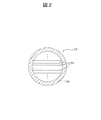
- FIG. 1 schematically shows an example of a hydrogenation reactor.
- the hydrogenation reactor 300 includes a plurality of reaction cells 31 having a columnar outer shape, and a cylindrical first casing 32 for accommodating the plurality of reaction cells 31. .. Then, carbon dioxide contained in the exhaust gas, a gas containing hydrogen produced by the electrolyzer, a dehydrogenator, for example, vapor of toluene, etc., flows through each reaction cell 31, and cooling water flows out of the reaction cell 31. Therefore, it is designed to pass through the inside of the first casing 32.
- the first casing 32 and the second casing 34 described below are made of metal (for example, SUS) so as to have high thermal conductivity.
- the shapes of the first casing 32 and the second casing 34 are not limited to a cylindrical shape, and may be, for example, a quadrangular tubular shape or a polygonal tubular shape.
- the reaction cell 31 includes a plurality of laminated reaction sheets 33 and a second casing 34 for accommodating the plurality of reaction sheets 33.
- each reaction sheet 33 includes a base metal foil 35, a porous layer 36 formed on both sides of the metal foil 35, and a catalyst 37 supported on the porous layer 36. ing. That is, each reaction sheet 33 has a three-layer structure in which the porous layer 36 supporting the catalyst 37, the metal foil 35, and the porous layer 36 supporting the catalyst 37 are laminated in this order.
- a gap is formed between the reaction sheets 33 adjacent to each other in the thickness direction through which gas components such as carbon dioxide, water vapor, generated hydrogen, and a dehydrogenator, for example, toluene vapor can pass.
- gas components such as carbon dioxide, water vapor, generated hydrogen, and a dehydrogenator, for example, toluene vapor can pass.
- reaction sheet 33 is in the form of a sheet, its heat capacity is small, heat is rapidly conducted through the reaction sheet 33, and the temperature at which the catalyst 37 exerts its catalytic function well is quickly adjusted.
- hydrogen supplied from the electrolyzer reacts with carbon dioxide or toluene and is efficiently converted into a hydrogen reservoir such as methane or methylcyclohexane.
- each reaction sheet 33 Further, a plurality of through holes 33a are formed in each reaction sheet 33.
- carbon dioxide, water vapor, generated hydrogen and dehydrogenated substances such as toluene vapor, which are gas components, can flow well in the thickness direction.
- the metal foil 35 is made of, for example, an aluminum foil, and its thickness is usually 50 ⁇ m to 200 ⁇ m.
- the metal foil 35 may not be provided, or instead of the metal foil 35, the base porous layer 36 may be provided, and the entire reaction sheet 33 may have a porous structure.
- the porous layer 36 is a layer for supporting the catalyst 37, and has a plurality of pores through which gas components such as carbon dioxide, water vapor, generated hydrogen and dehydrogenate, for example, toluene vapor can pass. Have.
- a porous layer 36 is composed of, for example, an oxide mainly composed of alumina.
- the catalyst 37 is a catalyst for producing methane or a hydrogen reservoir from generated hydrogen, which is a gas component, and carbon dioxide or a dehydrogenator, for example, vapor of toluene or the like.
- a catalyst 37 is as described above and may differ depending on the hydrogenation reaction, but typical catalysts include, for example, platinum, nickel, palladium, rhodium, iridium, ruthenium, molybdenum, rhenium, and tungsten. , Vanadium, osmium, chromium, cobalt, iron and the like.
- the fuel production apparatus of the present invention may further include a cooling apparatus or a cooling water line for adjusting the temperature of hydrogen or the like supplied to the hydrogenation reactor and the reaction temperature of the hydrogenation reactor.
- the internal combustion engine, the hydrogenation reactor, and in some cases, the cooling device may be connected by a cooling water line for cooling the internal combustion engine.
- the cooling device is a device for adjusting the temperature of hydrogen or the like supplied to the hydrogenation reactor, and the cooling water line appropriately adjusts the temperature of the internal combustion engine, the cooling device and / or the hydrogenation device.
- the cooling device and the cooling water line those known in the art can be used.
- the temperature of the metanation reactor is appropriately adjusted by connecting the internal combustion engine and the metanation reactor with a cooling water line.
- the reaction temperature can be adjusted.
- a cooling device that cools by drainage between the electrolyzer and the metanation reactor, the generated hydrogen and carbon dioxide can be adjusted to a temperature range suitable for the start temperature of the metanation reaction, and the said.
- Energy efficiency can be improved by supplying the wastewater that has become hot due to heat exchange in the cooling device to the electrolyzer as hot water or steam.
- water contained in the methane mixed gas generated in the metanation reactor can be used. Separation of water from the methane mixed gas can be carried out by cooling the methane mixed gas to less than 100 ° C. in a cooling device installed after the metanation reactor and separating the gaseous methane and the liquid water. can.
- the reaction temperature of the organic hydride reactor can be adjusted by connecting the internal combustion engine and the organic hydride reactor with a cooling water line. Can be adjusted appropriately.
- the generated hydrogen can be adjusted to a temperature range suitable for the start temperature of the hydrogenation reaction, and the hydrogen supplied to the organic hydride reactor can be adjusted. Excess water vapor can be removed from the gas to improve the reaction efficiency in the organic hydride reactor.
- FIG. 4 shows the configuration of the first embodiment of the fuel manufacturing apparatus of the present invention.
- the configuration of the first embodiment includes an internal combustion engine 1, an electrolyzer 2 connected to the internal combustion engine 1, and a hydrogenation reactor 300 connected to the electrolyzer 2 in series.
- a fuel tank 4 for supplying fuel to the internal combustion engine 1 and a generator 5 operated by the mechanical power of the internal combustion engine 1 are further connected to the internal combustion engine 1, and the internal combustion engine 1 and the electrolysis device 2 are connected.
- a renewable energy source 6 for supplying electric power to the electrolyzer 2 is further connected to the electrolyzer 2.
- a storage tank 700 for storing the fuel produced in the hydrogenation reactor 300 is further connected to the hydrogenation reactor 300.
- the fuel supplied from the fuel tank 4 to the internal combustion engine 1 is burned to generate steam at 400 ° C. and mechanical power, and the steam at 400 ° C. is supplied to the electrolysis device 2.
- Mechanical power is transmitted to the generator 5.
- the steam at 400 ° C. supplied to the electrolyzer 2 operated by the renewable energy source 6 is decomposed into oxygen and hydrogen by high-temperature electrolysis, oxygen is supplied to the internal combustion engine 1, and hydrogen is a hydrogenation reaction. It is supplied to the vessel 300.
- the hydrogen supplied to the hydrogenation reactor 300 is converted into fuel for methane or methylcyclohexane (MCH) and stored in the storage tank 700.
- MCH methane or methylcyclohexane
- the hydrogen generated in the electrolyzer 2 is supplied to the hydrogenation reactor 300 connected in series with the electrolyzer 2 at a high temperature, and is therefore heated for the hydrogenation reaction. It is not necessary and can be converted into a form that is easy to store.
- FIG. 5 shows the configuration of the second embodiment in which the metanation reactor 301 is used as the hydrogenation reactor in the fuel production apparatus of the present invention.
- the configuration of the second embodiment includes an internal combustion engine 1, an electrolyzer 2 connected to the internal combustion engine 1, and a metanation reactor 301 connected to the electrolyzer 2 in series.
- a fuel tank 4 for supplying fuel to the internal combustion engine 1 and a generator 5 operated by the mechanical power of the internal combustion engine 1 are further connected to the internal combustion engine 1, and the internal combustion engine 1 and the electrolysis device 2 are connected.
- a renewable energy source 6 for supplying electric power to the electrolyzer 2 is further connected to the electrolyzer 2.
- a methane storage tank 701 for storing methane produced in the methane reactor 301 is further connected to the methane reactor 301.
- the internal combustion engine 1 and the metanation reactor 301 may be connected by a cooling water line.
- the fuel supplied from the fuel tank 4 to the internal combustion engine 1 is burned to generate steam, carbon dioxide and mechanical power at 400 ° C., and the steam and carbon dioxide at 400 ° C. are electric. It is supplied to the disassembling device 2 and the mechanical power is transmitted to the generator 5.
- the ratio of fuel and oxygen supplied to the internal combustion engine 1 so as to be stoichiometric combustion, almost all oxygen is consumed at the time of combustion, and oxygen is not contained in the exhaust gas.
- the gas temperature (outlet side gas temperature) of methane discharged from the methane reactor 301 is preferably 220 ° C. to 250 depending on the cooling device and / or the cooling water line or the like arranged in front of the methane reactor 301. Set to ° C.
- the hydrogen generated in the electrolyzer 2 and the carbon dioxide contained in the exhaust gas are supplied to the methane reactor 301 connected in series with the electrolyzer 2 at a high temperature. It can be converted to methane, which is easy to store, without the need for heating for metanation.
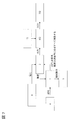
- FIG. 6 shows the configuration of the third embodiment, which is a further embodiment of the second embodiment.
- the configuration of the third embodiment is an internal combustion engine 1, a three-way catalyst 8 for removing harmful substances connected to the internal combustion engine 1, an electrolysis device 2 connected to the three-way catalyst 8, and the electrolysis.
- a first cooling device 9 for adjusting the temperature suitable for the metanation reaction connected to the device 2 and a metanation reactor 301 connected to the first cooling device 9 are included in series.
- a second cooling device 10 for cooling the water (water vapor) generated in the metanation reactor 301 is connected to the subsequent stage of the metanation reactor 301, and a second cooling device 10 is connected to the subsequent stage of the second cooling device 10.
- a water recovery tank 11 for recovering the cooled water is connected, and a methane storage tank 701 for recovering the generated methane mixed gas is connected to the subsequent stage of the water recovery tank 11.
- the internal combustion engine 1 further includes a cooling water line (including a cooling water pump 12, a cooling water tank 13, and a radiator 14) connecting the internal combustion engine 1, the second cooling device 10, and the metanation reactor 301.
- the first cooling device 9 supplies the piping for supplying wastewater that can be a cooling medium from the water recovery tank 11 and the high-temperature wastewater or steam that has been heat-exchanged in the first cooling device 9 to the electrolysis device 2.
- the piping for cooling is further connected.
- the fuel supplied from the fuel tank to the internal combustion engine for example, methane is burned to generate water vapor and carbon dioxide at 350 ° C. to 550 ° C. (CH 4 + 2O 2 ⁇ CO 2). + 2H 2 O (Formula 1)), the high-temperature water vapor and carbon dioxide are supplied to the electrolytic converter 2 after the harmful substances (unburned hydrocarbons, carbon monoxide, nitrogen oxide, etc.) are removed by the three-way catalyst 8. Will be done. At this time, by adjusting the ratio of fuel and oxygen supplied to the internal combustion engine 1 so as to be stoichiometric combustion, oxygen is not contained in the exhaust gas.
- the high-temperature water vapor supplied to the electrolyzer 2 is decomposed into oxygen and hydrogen by high-temperature electrolysis (CO 2 + 2H 2 O ⁇ 2H 2 + CO 2 + O 2 (Equation 2)), and hydrogen is released.
- the temperature is adjusted to 250 ° C. to 300 ° C., which is suitable for the start temperature of the metanation reaction, and then supplied to the metanation reactor 301.
- the carbon dioxide contained in the exhaust gas is also supplied to the metanation reactor 301 without being electrolyzed.
- Hydrogen and carbon dioxide supplied to the methanation reactor 301 are converted to methane and water vapor at an appropriate reaction temperature of 220 ° C to 260 ° C adjusted by the cooling water line (2H 2 + 2H 2 + CO 2). ⁇ CH 4 + 2H 2 O (Equation 3)).
- the converted methane and steam are supplied from the metanation reactor 301 to the second cooling device 10 at a temperature of 220 ° C. to 260 ° C.
- the water vapor is cooled to water and recovered in the water recovery tank 11, and the methane mixed gas from which the water is separated is recovered in the methane storage tank 701 further after the water recovery tank 11.
- the nitrogen contained in the exhaust gas (including the nitrogen converted by the three-way catalyst 8) is contained in the final product.
- Equation 1 1 mol of methane, which is the fuel of the internal combustion engine 1, is burned to generate 1 mol of carbon dioxide and 2 mol of water vapor (Equation 1), and 2 mol of water vapor is electricity.
- 2 mol of hydrogen is produced by electrolysis in the decomposition apparatus 2 (Equation 2). That is, 1 mol of carbon dioxide and 2 mol of hydrogen are produced from 1 mol of methane.
- 1 mol of carbon dioxide and 4 mol of hydrogen are required (Equation 3).
- 1 mol of carbon dioxide contained in the exhaust gas discharged from the internal combustion engine 1 is all of 2 mol of hydrogen generated by 2 mol of water vapor contained in the exhaust gas also discharged from the internal combustion engine 1.
- 2 mol of steam produced in the metanation reactor 301 that is, 2 mol of water recovered in the water recovery tank 11 is used.
- the hydrogen generated in the electrolyzer 2 and the carbon dioxide contained in the exhaust gas are supplied to the methane reactor 301 connected in series with the electrolyzer 2 at a high temperature. It can be converted to methane, which is easy to store, without the need for heating for metanation.
- FIG. 7 shows the configuration of the fourth embodiment in which the organic hydride reactor 302 is used as the hydrogenation reactor and toluene and methylcyclohexane are used as the organic hydride in the fuel production apparatus of the present invention.
- the configuration of the fourth embodiment includes an internal combustion engine 1, an electrolyzer 2 connected to the internal combustion engine 1, and an organic hydride reactor 302 connected to the electrolyzer 2.
- a fuel tank 4 for supplying fuel to the internal combustion engine 1 and a generator 5 operated by the mechanical power of the internal combustion engine 1 are further connected to the internal combustion engine 1, and the internal combustion engine 1 and the electrolysis device 2 are connected.
- the organic hydride reactor 302 further includes a methylcyclohexane storage tank 702 for storing the liquid methylcyclohexane produced in the organic hydride reactor 302, and a toluene storage tank 15 for storing toluene as a dehydrogenator. It is connected.
- a cooling device for adjusting the temperature suitable for the start temperature of the hydrogen addition reaction for example, a heat exchanger may be arranged between the electrolyzer 2 and the organic hydride reactor 302. Further, the internal combustion engine 1 and the organic hydride reactor 302 may be connected by a cooling water line.
- the fuel supplied from the fuel tank 4 to the internal combustion engine 1 is burned to generate steam at 400 ° C. and mechanical power, and the steam at 400 ° C. is supplied to the electrolysis device 2.
- Mechanical power is transmitted to the generator 5.
- the steam at 400 ° C. supplied to the electrolyzer 2 operated by the renewable energy source 6 is decomposed into oxygen and hydrogen by high-temperature electrolysis, oxygen is supplied to the internal combustion engine 1, and hydrogen is an organic hydride reaction. It is supplied to the vessel 302.
- the hydrogen supplied to the organic hydride reactor 302 reacts with the toluene supplied from the toluene storage tank 15 to be converted into liquid methylcyclohexane, and is stored in the methylcyclohexane storage tank 702.
- the temperature (outlet side temperature) of methylcyclohexane discharged from the organic hydride reactor 302 is preferably 85 ° C. to 98 ° C. depending on the cooling device and / or the cooling water line or the like arranged in front of the organic hydride reactor 302. Is set to.
- the hydrogen generated in the electrolyzer 2 is supplied to the organic hydride reactor 302 connected in series with the electrolyzer 2 at a high temperature, and is therefore heated for the hydrogenation reaction. It can be converted to a liquid methylcyclohexane that is not necessary and is easy to store.
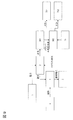
- FIG. 8 shows the configuration of the fifth embodiment, which is a further embodiment of the fourth embodiment.
- the configuration of the fifth embodiment is an internal combustion engine 1, a three-way catalyst 8 for removing harmful substances connected to the internal combustion engine 1, an electrolysis device 2 connected to the three-way catalyst 8, and the electrolysis.
- a cooling device 16 connected to the device 2 for adjusting to a temperature suitable for the hydrogen addition reaction, a toluene vaporizer 17 connected to the cooling device 16, and an organic hydride reaction connected to the toluene vaporizer 17.
- a toluene storage tank 15 for storing toluene as a dehydrogenator is further connected to the toluene vaporizer 17.
- the organic hydride reactor 302 is further connected to a methylcyclohexane storage tank 702 for storing the liquid methylcyclohexane produced in the organic hydride reactor 302.
- the internal combustion engine 1 further includes a cooling water line (including a cooling water pump 12, a cooling water tank 13, and a radiator 14) connecting the internal combustion engine 1, the cooling device 16, and the organic hydride reactor 302.
- the fuel supplied from the fuel tank to the internal combustion engine 1 is burned to generate high-temperature steam, and the high-temperature steam is a harmful substance (unburned hydrocarbon) in the three-way catalyst 8. , Carbon monoxide, nitrogen oxide, etc.) are removed before being supplied to the electrolytic converter 2.
- the ratio of fuel and oxygen supplied to the internal combustion engine 1 so as to be stoichiometric combustion, oxygen is not contained in the exhaust gas.
- the high-temperature water vapor supplied to the electrolysis device 2 is decomposed into oxygen and hydrogen by high-temperature electrolysis, and hydrogen is a temperature suitable for the start temperature of the hydrogen addition reaction to toluene in the cooling device 1680.
- the toluene vaporizer 17 After adjusting to ° C. to 90 ° C., it is supplied to the toluene vaporizer 17.
- the water generated by cooling is removed in the cooling device 16 or the water separation tank (not shown) connected to the cooling device 16.
- the hydrogen and nitrogen gas supplied to the toluene vaporizer 17 vaporize toluene having a vapor pressure in the toluene vaporizer 17, and are supplied to the organic hydride reactor 302 together with the toluene vapor.
- the hydrogen and toluene vapors supplied to the organic hydride reactor 302 are converted to methylcyclohexane at an appropriate reaction temperature of 85 ° C. to 96 ° C. adjusted by a cooling water line.
- the converted methylcyclohexane is supplied from the organic hydride reactor 302 to the methylcyclohexane storage tank 702 at a temperature of 85 ° C to 96 ° C.
- the nitrogen contained in the exhaust gas (including the nitrogen converted by the three-way catalyst) is finally discharged from the methylcyclohexane storage tank 702.
- the hydrogen generated in the electrolyzer 2 is supplied to the organic hydride reactor 302 connected in series with the electrolyzer 2 at a high temperature, and is therefore heated for the hydrogenation reaction. It can be converted to a liquid methylcyclohexane that is not necessary and is easy to store.
- FIG. 9 shows the configuration of the sixth embodiment in which the metanation reactor 301 and the organic hydride reactor 302 are used as the hydrogenation reactor in the fuel production apparatus of the present invention.
- the configuration of the sixth embodiment is connected to the internal combustion engine 1, the electrolyzer 2 connected to the internal combustion engine 1, the metanation reactor 301 connected to the electrolyzer 2, and the metanation reactor 301. Includes the organic hydride reactor 302 and the like.
- a fuel tank 4 for supplying fuel to the internal combustion engine 1 and a generator 5 operated by the mechanical power of the internal combustion engine 1 are further connected to the internal combustion engine 1, and the internal combustion engine 1 and the electrolysis device 2 are connected.
- the methanation reactor 301 includes a methane storage tank 701 for storing methane produced in the methanation reactor 301 and an organic hydride reaction for further reacting unreacted hydrogen in the methanation reactor 301. 302 is further connected.
- the organic hydride reactor 302 includes a methylcyclohexane storage tank 702 for storing the liquid methylcyclohexane produced in the organic hydride reactor 302 and a toluene storage tank 15 for storing toluene as a dehydrogenator. Further connected.
- a methylcyclohexane storage tank 702 for storing the liquid methylcyclohexane produced in the organic hydride reactor 302 and a toluene storage tank 15 for storing toluene as a dehydrogenator.
- Cooling devices such as heat exchangers may be arranged.
- the internal combustion engine 1, the metanation reactor 301, and the organic hydride reactor 302 may be connected by a cooling water line.
- the fuel supplied from the fuel tank 4 to the internal combustion engine 1 is burned to generate steam, carbon dioxide and mechanical power at 400 ° C., and the steam and carbon dioxide at 400 ° C. are electric. It is supplied to the disassembling device 2 and the mechanical power is transmitted to the generator 5.
- the ratio of fuel and oxygen supplied to the internal combustion engine 1 so as to be stoichiometric combustion, almost all oxygen is consumed at the time of combustion, and oxygen is not contained in the exhaust gas.
- the gas temperature (outlet side gas temperature) of methane discharged from the methane reactor 301 is preferably 220 ° C. to 250 depending on the cooling device and / or the cooling water line or the like arranged in front of the methane reactor 301. Set to ° C.
- the unreacted hydrogen in the metanation reactor 301 is supplied to the organic hydride reactor 302 while being mixed with the reaction product methane.
- the hydrogen in the mixed gas supplied to the organic hydride reactor 302 reacts with the toluene supplied from the toluene storage tank 15 to be converted into liquid methylcyclohexane, and is stored in the methylcyclohexane storage tank 702.
- Methane in the mixed gas does not participate in the formation reaction of methylcyclohexane, and methane can be separated by being discharged as a gas.
- the temperature (outlet side temperature) of methylcyclohexane discharged from the organic hydride reactor 302 is preferably 85 ° C. to 98 ° C. depending on the cooling device and / or the cooling water line or the like arranged in front of the organic hydride reactor 302. Is set to.
- the hydrogen generated in the electrolysis apparatus 2, the carbon dioxide contained in the exhaust gas, and the unreacted hydrogen in the methane reactor 301 are connected in series with the electrolysis reactor 2. Since the methane is supplied at a high temperature to the methaneation reactor 301 and the organic hydride reactor 302 connected in series with the methaneation reactor 301, it does not need to be heated for the methaneation and hydrogen addition reaction, and methane is easy to store. And can be converted to liquid methylcyclohexane.
- the present invention is not limited to the above-described embodiment, and includes various modifications. For example, it is possible to add / delete / replace a part of the configuration of the embodiment with another configuration.
Landscapes
- Engineering & Computer Science (AREA)
- Chemical & Material Sciences (AREA)
- Combustion & Propulsion (AREA)
- Mechanical Engineering (AREA)
- General Engineering & Computer Science (AREA)
- Chemical Kinetics & Catalysis (AREA)
- Organic Chemistry (AREA)
- Oil, Petroleum & Natural Gas (AREA)
- General Chemical & Material Sciences (AREA)
- Health & Medical Sciences (AREA)
- Inorganic Chemistry (AREA)
- General Health & Medical Sciences (AREA)
- Electrochemistry (AREA)
- Materials Engineering (AREA)
- Metallurgy (AREA)
- Organic Low-Molecular-Weight Compounds And Preparation Thereof (AREA)
- Electrolytic Production Of Non-Metals, Compounds, Apparatuses Therefor (AREA)
Abstract
Description
陰極:H2O + 2e- → O2- + H2↑
陽極:O2- → 2e- + 1/2O2↑
全体:H2O → H2 + 1/2O2
CO2 + 4H2 → CH4 + 2H2O
C6H5CH3 + 3H2 → C6H11CH3
Claims (11)
- 内燃機関と当該内燃機関に接続されている電気分解装置と当該電気分解装置に接続されている水素化反応器とを含み、電気分解装置が内燃機関からの排気ガス中に含まれる高温の水蒸気を水素と酸素とに分解するための装置であり、水素化反応器が分解された水素を燃料に変換するための装置である燃料製造装置。
- 分解された酸素を内燃機関に供給するための配管をさらに含む請求項1に記載の燃料製造装置。
- 水素化反応器が、メタネーション反応器であり、メタネーション反応器が、分解された水素と排気ガス中に含まれる二酸化炭素とを反応させてメタンに変換するための装置である請求項1に記載の燃料製造装置。
- 電気分解装置とメタネーション反応器の間に冷却装置をさらに含み、冷却装置が、分解された水素及び排気ガス中に含まれる二酸化炭素を200℃~250℃に調整するための装置である請求項3に記載の燃料製造装置。
- 水素化反応器が、有機ハイドライド反応器であり、有機ハイドライド反応器が、分解された水素と脱水素体とを反応させて水素貯蔵体に変換するための装置である請求項1に記載の燃料製造装置。
- 脱水素体がトルエンであり、水素貯蔵体がメチルシクロヘキサンである請求項5に記載の燃料製造装置。
- 電気分解装置と有機ハイドライド反応器の間に冷却装置をさらに含み、冷却装置が、分解された水素を85℃~98℃に調整するための装置である請求項6に記載の燃料製造装置。
- 内燃機関が、内燃機関と水素化反応器の間をつなぐ冷却水ラインをさらに含み、冷却水ラインが、水素化反応器における反応温度を調整するための機関である請求項1~7のいずれか一項に記載の燃料製造装置。
- 内燃機関において燃料をストイキ燃焼することで高温の水蒸気及び二酸化炭素を生成する第1のステップと、
第1のステップにおいて生成した高温の水蒸気を電気分解装置により水素及び酸素に分解する第2のステップと、
第2のステップにおいて分解した水素を水素化反応器において燃料に変換する第3のステップと
を含む燃料を製造する方法。 - 第3のステップにおいて、水素化反応器としてメタネーション反応器を使用し、水素及び二酸化炭素を、冷却装置により200℃~250℃に調整し、メタネーション反応器においてメタンに変換する請求項9に記載の方法。
- 第3のステップにおいて、水素化反応器として有機ハイドライド反応器を使用し、水素を、冷却装置により85℃~98℃に調整し、有機ハイドライド反応器において脱水素体としてのトルエンと反応させてメチルシクロヘキサンに変換する請求項9に記載の方法。
Priority Applications (4)
| Application Number | Priority Date | Filing Date | Title |
|---|---|---|---|
| PCT/JP2020/013721 WO2021192156A1 (ja) | 2020-03-26 | 2020-03-26 | 燃料製造装置 |
| JP2022510269A JP7253670B2 (ja) | 2020-03-26 | 2020-03-26 | 燃料製造装置 |
| US17/639,748 US11732624B2 (en) | 2020-03-26 | 2020-03-26 | Fuel production device |
| EP20927176.6A EP4130205B1 (en) | 2020-03-26 | 2020-03-26 | Fuel production device |
Applications Claiming Priority (1)
| Application Number | Priority Date | Filing Date | Title |
|---|---|---|---|
| PCT/JP2020/013721 WO2021192156A1 (ja) | 2020-03-26 | 2020-03-26 | 燃料製造装置 |
Publications (1)
| Publication Number | Publication Date |
|---|---|
| WO2021192156A1 true WO2021192156A1 (ja) | 2021-09-30 |
Family
ID=77891001
Family Applications (1)
| Application Number | Title | Priority Date | Filing Date |
|---|---|---|---|
| PCT/JP2020/013721 Ceased WO2021192156A1 (ja) | 2020-03-26 | 2020-03-26 | 燃料製造装置 |
Country Status (4)
| Country | Link |
|---|---|
| US (1) | US11732624B2 (ja) |
| EP (1) | EP4130205B1 (ja) |
| JP (1) | JP7253670B2 (ja) |
| WO (1) | WO2021192156A1 (ja) |
Cited By (1)
| Publication number | Priority date | Publication date | Assignee | Title |
|---|---|---|---|---|
| CN114792992A (zh) * | 2022-04-26 | 2022-07-26 | 哈尔滨工业大学(深圳) | 一种基于海上可再生能源制氢的离岸水电供应系统及方法 |
Citations (5)
| Publication number | Priority date | Publication date | Assignee | Title |
|---|---|---|---|---|
| JP2006206931A (ja) * | 2005-01-25 | 2006-08-10 | Denso Corp | 水素発生装置およびこの水素発生装置で生成した水素を燃料として発電する発電システム |
| JP2009007547A (ja) * | 2007-05-25 | 2009-01-15 | Tokyo Metropolitan Univ | 核酸キャリア及び核酸デリバリー方法 |
| WO2012147157A1 (ja) * | 2011-04-26 | 2012-11-01 | 株式会社日立製作所 | エネルギ貯蔵供給装置 |
| JP2016531973A (ja) * | 2013-07-09 | 2016-10-13 | ミツビシ ヒタチ パワー システムズ ヨーロッパ ゲーエムベーハー | メタネーション方法および電力プラント煙道ガスの二酸化炭素メタネーションを備える電力プラント |
| JP2018523046A (ja) * | 2015-06-16 | 2018-08-16 | サウジ アラビアン オイル カンパニーSaudi Arabian Oil Company | Co2を燃料に車両上で変換する方法及びそのための装置 |
Family Cites Families (11)
| Publication number | Priority date | Publication date | Assignee | Title |
|---|---|---|---|---|
| JP4297488B2 (ja) * | 2003-08-21 | 2009-07-15 | 東京瓦斯株式会社 | 内燃機関 |
| JP2009007647A (ja) | 2007-06-29 | 2009-01-15 | Hitachi Ltd | 有機ハイドライド製造装置、及び、それを用いた分散電源と自動車 |
| EP2685076B1 (en) * | 2011-03-08 | 2016-05-11 | Toyota Jidosha Kabushiki Kaisha | Vehicle with mixed gas generating system, and vehicle with fuel producing system |
| JP5759263B2 (ja) * | 2011-05-24 | 2015-08-05 | Jx日鉱日石エネルギー株式会社 | 単環芳香族炭化水素の製造方法 |
| GB201202791D0 (en) | 2012-02-20 | 2012-04-04 | Simpson Robert | Methods and system for energy conversion and generation |
| JP5982253B2 (ja) * | 2012-10-24 | 2016-08-31 | 株式会社日立製作所 | コージェネレーションシステム |
| JP2015209576A (ja) * | 2014-04-28 | 2015-11-24 | パナソニックIpマネジメント株式会社 | 反応器、反応器の運転方法および反応器システム |
| JP2015222712A (ja) * | 2014-04-28 | 2015-12-10 | パナソニックIpマネジメント株式会社 | 反応器および反応器の作動方法 |
| JP2018204433A (ja) * | 2015-09-25 | 2018-12-27 | 株式会社日立製作所 | 内燃機関 |
| ITUB20155235A1 (it) * | 2015-10-29 | 2017-04-29 | St Microelectronics Srl | Gruppo motopropulsore comprendente un motore a combustibile misto, e metodo di alimentazione di tale motore |
| DE102017210324A1 (de) * | 2017-06-20 | 2018-12-20 | Mtu Friedrichshafen Gmbh | Energiewandlungseinrichtung zur Umwandlung elektrischer Energie in chemische Energie, Stromnetz mit einer solchen Energiewandlungseinrichtung, und Verfahren zum Betreiben einer solchen Energiewandlungseinrichtung |
-
2020
- 2020-03-26 JP JP2022510269A patent/JP7253670B2/ja active Active
- 2020-03-26 US US17/639,748 patent/US11732624B2/en active Active
- 2020-03-26 EP EP20927176.6A patent/EP4130205B1/en active Active
- 2020-03-26 WO PCT/JP2020/013721 patent/WO2021192156A1/ja not_active Ceased
Patent Citations (5)
| Publication number | Priority date | Publication date | Assignee | Title |
|---|---|---|---|---|
| JP2006206931A (ja) * | 2005-01-25 | 2006-08-10 | Denso Corp | 水素発生装置およびこの水素発生装置で生成した水素を燃料として発電する発電システム |
| JP2009007547A (ja) * | 2007-05-25 | 2009-01-15 | Tokyo Metropolitan Univ | 核酸キャリア及び核酸デリバリー方法 |
| WO2012147157A1 (ja) * | 2011-04-26 | 2012-11-01 | 株式会社日立製作所 | エネルギ貯蔵供給装置 |
| JP2016531973A (ja) * | 2013-07-09 | 2016-10-13 | ミツビシ ヒタチ パワー システムズ ヨーロッパ ゲーエムベーハー | メタネーション方法および電力プラント煙道ガスの二酸化炭素メタネーションを備える電力プラント |
| JP2018523046A (ja) * | 2015-06-16 | 2018-08-16 | サウジ アラビアン オイル カンパニーSaudi Arabian Oil Company | Co2を燃料に車両上で変換する方法及びそのための装置 |
Non-Patent Citations (1)
| Title |
|---|
| See also references of EP4130205A4 |
Cited By (1)
| Publication number | Priority date | Publication date | Assignee | Title |
|---|---|---|---|---|
| CN114792992A (zh) * | 2022-04-26 | 2022-07-26 | 哈尔滨工业大学(深圳) | 一种基于海上可再生能源制氢的离岸水电供应系统及方法 |
Also Published As
| Publication number | Publication date |
|---|---|
| EP4130205A1 (en) | 2023-02-08 |
| US20220333515A1 (en) | 2022-10-20 |
| EP4130205B1 (en) | 2025-04-23 |
| JPWO2021192156A1 (ja) | 2021-09-30 |
| JP7253670B2 (ja) | 2023-04-06 |
| EP4130205A4 (en) | 2024-01-17 |
| US11732624B2 (en) | 2023-08-22 |
Similar Documents
| Publication | Publication Date | Title |
|---|---|---|
| DK2905359T3 (en) | Renewable energy storage system | |
| JP2009007647A (ja) | 有機ハイドライド製造装置、及び、それを用いた分散電源と自動車 | |
| CN109638324B (zh) | 针对多种碳氢燃料的一体化多套管结构的纯氢催化装置及pemfc发电系统 | |
| CN104362355A (zh) | 一种甲醇水制氢机及其制氢方法 | |
| JP6194143B2 (ja) | 水素及び合成天然ガスの製造装置及び製造方法 | |
| JP5046359B2 (ja) | 水素発生装置および水素添加反応装置 | |
| JP6437191B2 (ja) | 水素製造システム及びこれを備えた水素貯蔵・輸送システム並びに水素製造方法 | |
| JP7176025B2 (ja) | 発電装置 | |
| WO2013145674A1 (ja) | 燃料電池モジュール及び燃料電池システム | |
| JP2012206909A (ja) | ハイブリッド型水素製造・発電システム | |
| JP5174602B2 (ja) | 水素貯蔵システム | |
| Zhao et al. | A Comprehensive Review of Ammonia Decomposition for Hydrogen Production | |
| JP2015051901A (ja) | エネルギー供給システム及びエネルギー供給方法 | |
| JP5602698B2 (ja) | 動力変換システム | |
| JP5297251B2 (ja) | 水素供給方法及び水素供給装置 | |
| JP7253670B2 (ja) | 燃料製造装置 | |
| JP5982253B2 (ja) | コージェネレーションシステム | |
| WO2011152366A1 (ja) | エネルギー生成システム | |
| KR20240074838A (ko) | 수성 암모니아 공급물로부터의 조합된 수소 및 전기 생산 | |
| CN216336599U (zh) | 一种乙醇氧化重整制氢的装置 | |
| CN105655615A (zh) | 一种车用甲醇燃料电池系统及其工作方法 | |
| JP2018204433A (ja) | 内燃機関 | |
| CN204281300U (zh) | 一种甲醇水制氢机 | |
| JP2010030843A (ja) | 水素製造用触媒、それを用いた水素製造装置 | |
| Sameer et al. | Hydrogen production and utilization through electrochemical techniques |
Legal Events
| Date | Code | Title | Description |
|---|---|---|---|
| 121 | Ep: the epo has been informed by wipo that ep was designated in this application |
Ref document number: 20927176 Country of ref document: EP Kind code of ref document: A1 |
|
| ENP | Entry into the national phase |
Ref document number: 2022510269 Country of ref document: JP Kind code of ref document: A |
|
| NENP | Non-entry into the national phase |
Ref country code: DE |
|
| ENP | Entry into the national phase |
Ref document number: 2020927176 Country of ref document: EP Effective date: 20221026 |
|
| WWG | Wipo information: grant in national office |
Ref document number: 2020927176 Country of ref document: EP |