WO2021193012A1 - フォロア軸受 - Google Patents
フォロア軸受 Download PDFInfo
- Publication number
- WO2021193012A1 WO2021193012A1 PCT/JP2021/009249 JP2021009249W WO2021193012A1 WO 2021193012 A1 WO2021193012 A1 WO 2021193012A1 JP 2021009249 W JP2021009249 W JP 2021009249W WO 2021193012 A1 WO2021193012 A1 WO 2021193012A1
- Authority
- WO
- WIPO (PCT)
- Prior art keywords
- face
- seal
- follower bearing
- end surface
- ring
- Prior art date
- Legal status (The legal status is an assumption and is not a legal conclusion. Google has not performed a legal analysis and makes no representation as to the accuracy of the status listed.)
- Ceased
Links
Images




Classifications
-
- F—MECHANICAL ENGINEERING; LIGHTING; HEATING; WEAPONS; BLASTING
- F16—ENGINEERING ELEMENTS AND UNITS; GENERAL MEASURES FOR PRODUCING AND MAINTAINING EFFECTIVE FUNCTIONING OF MACHINES OR INSTALLATIONS; THERMAL INSULATION IN GENERAL
- F16C—SHAFTS; FLEXIBLE SHAFTS; ELEMENTS OR CRANKSHAFT MECHANISMS; ROTARY BODIES OTHER THAN GEARING ELEMENTS; BEARINGS
- F16C19/00—Bearings with rolling contact, for exclusively rotary movement
- F16C19/22—Bearings with rolling contact, for exclusively rotary movement with bearing rollers essentially of the same size in one or more circular rows, e.g. needle bearings
- F16C19/24—Bearings with rolling contact, for exclusively rotary movement with bearing rollers essentially of the same size in one or more circular rows, e.g. needle bearings for radial load mainly
- F16C19/26—Bearings with rolling contact, for exclusively rotary movement with bearing rollers essentially of the same size in one or more circular rows, e.g. needle bearings for radial load mainly with a single row of rollers
-
- F—MECHANICAL ENGINEERING; LIGHTING; HEATING; WEAPONS; BLASTING
- F16—ENGINEERING ELEMENTS AND UNITS; GENERAL MEASURES FOR PRODUCING AND MAINTAINING EFFECTIVE FUNCTIONING OF MACHINES OR INSTALLATIONS; THERMAL INSULATION IN GENERAL
- F16C—SHAFTS; FLEXIBLE SHAFTS; ELEMENTS OR CRANKSHAFT MECHANISMS; ROTARY BODIES OTHER THAN GEARING ELEMENTS; BEARINGS
- F16C33/00—Parts of bearings; Special methods for making bearings or parts thereof
- F16C33/72—Sealings
- F16C33/76—Sealings of ball or roller bearings
- F16C33/80—Labyrinth sealings
-
- F—MECHANICAL ENGINEERING; LIGHTING; HEATING; WEAPONS; BLASTING
- F16—ENGINEERING ELEMENTS AND UNITS; GENERAL MEASURES FOR PRODUCING AND MAINTAINING EFFECTIVE FUNCTIONING OF MACHINES OR INSTALLATIONS; THERMAL INSULATION IN GENERAL
- F16C—SHAFTS; FLEXIBLE SHAFTS; ELEMENTS OR CRANKSHAFT MECHANISMS; ROTARY BODIES OTHER THAN GEARING ELEMENTS; BEARINGS
- F16C33/00—Parts of bearings; Special methods for making bearings or parts thereof
- F16C33/72—Sealings
- F16C33/76—Sealings of ball or roller bearings
- F16C33/78—Sealings of ball or roller bearings with a diaphragm, disc, or ring, with or without resilient members
- F16C33/7816—Details of the sealing or parts thereof, e.g. geometry, material
-
- F—MECHANICAL ENGINEERING; LIGHTING; HEATING; WEAPONS; BLASTING
- F16—ENGINEERING ELEMENTS AND UNITS; GENERAL MEASURES FOR PRODUCING AND MAINTAINING EFFECTIVE FUNCTIONING OF MACHINES OR INSTALLATIONS; THERMAL INSULATION IN GENERAL
- F16C—SHAFTS; FLEXIBLE SHAFTS; ELEMENTS OR CRANKSHAFT MECHANISMS; ROTARY BODIES OTHER THAN GEARING ELEMENTS; BEARINGS
- F16C33/00—Parts of bearings; Special methods for making bearings or parts thereof
- F16C33/72—Sealings
- F16C33/76—Sealings of ball or roller bearings
- F16C33/78—Sealings of ball or roller bearings with a diaphragm, disc, or ring, with or without resilient members
- F16C33/7889—Sealings of ball or roller bearings with a diaphragm, disc, or ring, with or without resilient members mounted to an inner race and extending toward the outer race
-
- F—MECHANICAL ENGINEERING; LIGHTING; HEATING; WEAPONS; BLASTING
- F16—ENGINEERING ELEMENTS AND UNITS; GENERAL MEASURES FOR PRODUCING AND MAINTAINING EFFECTIVE FUNCTIONING OF MACHINES OR INSTALLATIONS; THERMAL INSULATION IN GENERAL
- F16C—SHAFTS; FLEXIBLE SHAFTS; ELEMENTS OR CRANKSHAFT MECHANISMS; ROTARY BODIES OTHER THAN GEARING ELEMENTS; BEARINGS
- F16C43/00—Assembling bearings
- F16C43/04—Assembling rolling-contact bearings
- F16C43/045—Mounting or replacing seals
-
- F—MECHANICAL ENGINEERING; LIGHTING; HEATING; WEAPONS; BLASTING
- F16—ENGINEERING ELEMENTS AND UNITS; GENERAL MEASURES FOR PRODUCING AND MAINTAINING EFFECTIVE FUNCTIONING OF MACHINES OR INSTALLATIONS; THERMAL INSULATION IN GENERAL
- F16H—GEARING
- F16H53/00—Cams or cam-followers, e.g. rollers for gearing mechanisms
- F16H53/06—Cam-followers
-
- F—MECHANICAL ENGINEERING; LIGHTING; HEATING; WEAPONS; BLASTING
- F16—ENGINEERING ELEMENTS AND UNITS; GENERAL MEASURES FOR PRODUCING AND MAINTAINING EFFECTIVE FUNCTIONING OF MACHINES OR INSTALLATIONS; THERMAL INSULATION IN GENERAL
- F16C—SHAFTS; FLEXIBLE SHAFTS; ELEMENTS OR CRANKSHAFT MECHANISMS; ROTARY BODIES OTHER THAN GEARING ELEMENTS; BEARINGS
- F16C19/00—Bearings with rolling contact, for exclusively rotary movement
- F16C19/22—Bearings with rolling contact, for exclusively rotary movement with bearing rollers essentially of the same size in one or more circular rows, e.g. needle bearings
- F16C19/44—Needle bearings
- F16C19/46—Needle bearings with one row or needles
-
- F—MECHANICAL ENGINEERING; LIGHTING; HEATING; WEAPONS; BLASTING
- F16—ENGINEERING ELEMENTS AND UNITS; GENERAL MEASURES FOR PRODUCING AND MAINTAINING EFFECTIVE FUNCTIONING OF MACHINES OR INSTALLATIONS; THERMAL INSULATION IN GENERAL
- F16C—SHAFTS; FLEXIBLE SHAFTS; ELEMENTS OR CRANKSHAFT MECHANISMS; ROTARY BODIES OTHER THAN GEARING ELEMENTS; BEARINGS
- F16C2360/00—Engines or pumps
- F16C2360/22—Internal combustion engines
-
- F—MECHANICAL ENGINEERING; LIGHTING; HEATING; WEAPONS; BLASTING
- F16—ENGINEERING ELEMENTS AND UNITS; GENERAL MEASURES FOR PRODUCING AND MAINTAINING EFFECTIVE FUNCTIONING OF MACHINES OR INSTALLATIONS; THERMAL INSULATION IN GENERAL
- F16C—SHAFTS; FLEXIBLE SHAFTS; ELEMENTS OR CRANKSHAFT MECHANISMS; ROTARY BODIES OTHER THAN GEARING ELEMENTS; BEARINGS
- F16C33/00—Parts of bearings; Special methods for making bearings or parts thereof
- F16C33/30—Parts of ball or roller bearings
- F16C33/66—Special parts or details in view of lubrication
- F16C33/6637—Special parts or details in view of lubrication with liquid lubricant
- F16C33/6659—Details of supply of the liquid to the bearing, e.g. passages or nozzles
- F16C33/6677—Details of supply of the liquid to the bearing, e.g. passages or nozzles from radial inside, e.g. via a passage through the shaft and/or inner ring
-
- F—MECHANICAL ENGINEERING; LIGHTING; HEATING; WEAPONS; BLASTING
- F16—ENGINEERING ELEMENTS AND UNITS; GENERAL MEASURES FOR PRODUCING AND MAINTAINING EFFECTIVE FUNCTIONING OF MACHINES OR INSTALLATIONS; THERMAL INSULATION IN GENERAL
- F16C—SHAFTS; FLEXIBLE SHAFTS; ELEMENTS OR CRANKSHAFT MECHANISMS; ROTARY BODIES OTHER THAN GEARING ELEMENTS; BEARINGS
- F16C35/00—Rigid support of bearing units; Housings, e.g. caps, covers
- F16C35/04—Rigid support of bearing units; Housings, e.g. caps, covers in the case of ball or roller bearings
- F16C35/06—Mounting or dismounting of ball or roller bearings; Fixing them onto shaft or in housing
- F16C35/063—Fixing them on the shaft
Definitions
- This disclosure relates to follower bearings.
- a follower bearing in which the outer ring rotates while in contact with other members is known (see, for example, Patent Document 1).
- Patent Document 1 an inner member having a first rolling surface, an outer ring having a second rolling surface facing the first rolling surface, and rolling on the first rolling surface and the second rolling surface.
- a follower bearing is disclosed that includes a plurality of rolling elements that are movably arranged and a sealing member that is arranged between an inner member and an outer ring.
- the inner member of the follower bearing has an annular collar.
- the follower bearing disclosed in Patent Document 1 is assembled by inserting the inner member into the outer ring with the seal member installed on the collar of the inner member.
- the seal member is arranged so as to form a seal structure with the outer ring.
- the seal structure has a gap formed between the outer ring and the seal member, or the outer ring and the seal member, in order to reduce grease leakage from the inside of the follower bearing and foreign matter from entering the inside. Is a structure that makes contact.
- the follower bearing of Patent Document 1 when the inner member is inserted into the outer ring, the outer ring may be caught by the seal member, which makes it difficult to install the outer ring during assembly. Therefore, one of the purposes is to provide a follower bearing that is easy to assemble.
- the follower bearing according to the present disclosure has a rod-shaped shape, a first main body portion having an annular first rolling surface as an outer peripheral surface, and a disk annular shape, which is one of the first main body portions.
- An inner member that is arranged on the outer peripheral surface of the end portion and has a central axis coaxial with the first main body portion and has a diameter larger than that of the first main body portion, and faces the outer peripheral surface of the flange portion.
- An outer ring having an annular first surface and an annular second rolling surface facing the first rolling surface on its inner peripheral surface, and on the first rolling surface and the second rolling surface.
- a first portion of an annular shape that is arranged between a plurality of rollable bodies that are rollably arranged and between the outer peripheral surface and the first surface of the collar portion, and at least a part of which forms a seal structure with the outer ring.
- a first seal member including the above.
- the first portion has a shape in which the outer diameter increases as it approaches the first end surface side, which is the end surface on the side opposite to the first rolling surface of the collar portion in the axial direction.
- the follower bearing can be easily assembled.
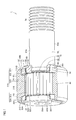
- FIG. 1 is a schematic perspective view showing the structure of a follower bearing.
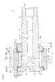
- FIG. 2 is a schematic cross-sectional view showing the structure of the follower bearing.
- FIG. 3 is a schematic cross-sectional view showing the structure of the follower bearing.
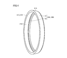
- FIG. 4 is a schematic perspective view showing the structure of the seal member.
- FIG. 5 is a schematic cross-sectional view for explaining a method of assembling the follower bearing.
- FIG. 6 is a schematic cross-sectional view for explaining a method of assembling the follower bearing.
- FIG. 7 is a schematic cross-sectional view for explaining a method of assembling the follower bearing.
- FIG. 8 is a schematic cross-sectional view for explaining a method of assembling the follower bearing.
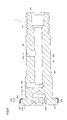
- FIG. 9 is a schematic cross-sectional view showing the structure of the follower bearing according to another embodiment.
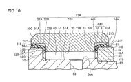
- FIG. 10 is a schematic cross-sectional view showing an enlarged region ⁇ of FIG.
- the follower bearing of the present disclosure has a rod-shaped shape, a first main body portion having an annular first rolling surface as an outer peripheral surface, and a disk annular shape, and one end portion of the first main body portion.
- An outer ring having an annular first surface and an annular second rolling surface facing the first rolling surface on its inner peripheral surface, and rolling on the first rolling surface and the second rolling surface.
- the first portion has a shape in which the outer diameter increases as it approaches the first end surface side, which is the end surface on the side opposite to the first rolling surface of the collar portion in the axial direction.
- the follower bearing of the present disclosure includes a first seal member.
- the first sealing member includes an annular first portion that is disposed between the outer peripheral surface of the collar and the first surface and forms a sealing structure with the outer ring.
- the first portion has a shape in which the outer diameter increases as it approaches the first end face side.
- the follower bearing is assembled by inserting an inner member having a first seal member installed on a flange portion into an outer ring. When the first seal member includes the first portion, the outer ring is guided by the first portion when the inner member is inserted into the outer ring, and the outer ring is less likely to be caught by the first seal member. Therefore, according to the follower bearing of the present disclosure, the follower bearing can be easily assembled.
- the first portion may have a tapered shape in which the outer diameter increases as it approaches the first end face side.
- the diameter of the second rolling surface may be smaller than the diameter of the first surface.
- the outer ring connects the second rolling surface and the first surface, and has an inner circumference of an annular second surface facing the second end surface, which is an end surface opposite to the first end surface of the collar portion in the axial direction. It may have more on the surface.
- the first seal member may further include an annular second portion that is connected to the first portion and is located between the second end surface and the second surface. Since the first seal member includes the second portion, it is possible to prevent the second end surface of the collar portion from coming into contact with the second surface of the outer ring when an axial load is applied to the follower bearing. Therefore, it is possible to suppress the occurrence of wear and the like due to the contact between the second end surface of the flange portion and the second surface of the outer ring.
- the maximum height roughness Rz of the second end surface of the flange portion may be 12.5 ⁇ m or less.
- the first seal member may include a first seal end face located on the first end face side in the axial direction.
- the first seal end face may have a shape in which the outer diameter becomes smaller as it approaches the first end face.
- the first seal end face may be tapered so that the outer diameter becomes smaller as it approaches the first end face side. By doing so, it is possible to make it easier for the dust accumulated on the end face of the first seal to slide down more reliably toward the end face side of the first seal. Therefore, it is possible to make it more difficult for dust to accumulate on the end face of the first seal. Therefore, it is possible to greatly reduce the possibility that dust on the end surface of the first seal gets over the outer peripheral surface of the first seal member and invades the inside of the bearing, and it is possible to further improve the dustproof performance of the follower bearing.
- the first seal end face may extend to the first end face in the axial direction.
- the inner member is fitted so as to be in contact with the outer peripheral surface on the side opposite to the flange portion when viewed from the first rolling surface of the first main body portion, and is a central shaft coaxial with the first main body portion.
- a ring having a bearing may be further included.
- the inner peripheral surface of the outer ring connects the third surface of the ring, which faces the outer peripheral surface of the ring and has a diameter larger than the diameter of the second rolling surface, and the second rolling surface and the third surface. It may further have an annular fourth surface facing a third end surface, which is an end surface on the first rolling surface side of the ring in the axial direction.
- the follower bearing is arranged between the outer peripheral surface and the third surface of the ring, and is connected to the third part and the third part of the annular shape, at least a part of which forms a seal structure with the outer ring, and is connected to the third part.
- a second sealing member including an annular fourth portion disposed between the three end faces and the fourth face may be further provided.
- the third portion may have a shape in which the outer diameter increases as it approaches the fourth end face side, which is the end face opposite to the third end face of the ring in the axial direction.
- the ring on which the second seal member is installed is attached to the first main body. Since the second seal member includes the third portion, when the ring on which the second seal member is installed is attached to the first main body portion, the ring is guided by the outer peripheral surface of the third portion, and the second seal member is an outer ring. It is less likely to get caught in. Therefore, the ring on which the second seal member is installed can be easily attached to the first main body portion. Further, since the second seal member includes the fourth portion, it is possible to prevent the third end surface and the fourth surface of the ring from coming into contact with each other when an axial load is applied to the follower bearing. Therefore, it is possible to suppress the occurrence of wear and the like due to the contact between the third end surface of the ring and the fourth surface of the outer ring.
- the third portion may have a tapered shape in which the outer diameter increases as it approaches the fourth end face side.
- the maximum height roughness Rz of the third end surface of the ring may be 12.5 ⁇ m or less.
- the second seal member may include a second seal end face located on the fourth end face side in the axial direction.
- the second seal end face may have a shape in which the outer diameter becomes smaller as it approaches the fourth end face.
- the second seal end face may have a tapered shape in which the outer diameter becomes smaller as it approaches the fourth end face side.
- the second seal end face may extend to the fourth end face in the axial direction.
- the material constituting the second seal member may be at least one resin selected from the group consisting of polyetheretherketone, polyacetal and polyamide.
- the resin is suitable as a material for forming the second seal member.
- the material constituting the first seal member may be at least one resin selected from the group consisting of polyetheretherketone, polyacetal and polyamide.
- the resin is suitable as a material constituting the first sealing member.
- the rolling element may be a roller. By doing so, it becomes easy to achieve a sufficient load capacity while suppressing the cross-sectional height of the follower bearing.
- FIG. 1 is a schematic perspective view showing the structure of the follower bearing according to the embodiment of the present disclosure.
- FIG. 1 a state in which some parts are partially cut is shown from the viewpoint of displaying the internal structure.
- the hatched region corresponds to a cross section.
- FIG. 2 is a schematic cross-sectional view showing the structure of the follower bearing.
- FIG. 2 shows a cross section including the rotation axis of the follower bearing.
- FIG. 3 is a schematic cross-sectional view showing an enlarged region ⁇ of FIG.
- the follower bearing 1 in the present embodiment includes an inner member 10, an outer ring 20, a first seal member 30A, a second seal member 30B, and a plurality of rolling elements. It is equipped with a roller 40.
- the follower bearing 1 is a full roller bearing that does not have a cage for the rollers 40.
- the inner member 10 includes a first main body portion 50, a flange portion 52 arranged on the outer peripheral surface of one end of the first main body portion 50, and a ring 60.
- the inner member 10 is made of steel.
- the first main body portion 50 has a rod-like (solid cylindrical shape) shape.
- a hexagonal hole 53A having a regular hexagonal columnar shape is formed so as to include a region of one end of the first main body 50 that intersects the central axis of the first main body 50 (orthogonal in the present embodiment). ing.
- a threaded portion 54 having a spiral threaded groove is arranged on the outer peripheral surface of the other end of the first main body portion 50.
- the first main body portion 50 has a large diameter portion 51 having a diameter slightly larger than that of other regions.
- the large diameter portion 51 is arranged closer to the collar portion 52 than the center in the axial direction.
- the large diameter portion 51 is arranged between the flange portion 52 and the screw portion 54, which will be described later, in the axial direction.
- the outer peripheral surface of the large diameter portion 51 includes a first rolling surface 51A having a cylindrical surface shape. That is, the first main body 50 has an annular first rolling surface 51A on the outer peripheral surface 50A.
- the first main body 50 has an opening 56A at an end opposite to the flange 52 in the axial direction, and a first hole 56 extending along the axial direction is formed.
- the first main body 50 has an opening 57A on the outer peripheral surface 50A of the first main body 50, and a second hole 57 extending along the radial direction is formed.
- the second hole 57 communicates with the first hole 56.
- the first main body portion 50 has an opening 58A in the first rolling surface 51A of the large diameter portion 51, and a third hole 58 extending along the radial direction is formed.
- the third hole 58 communicates with the first hole 56.
- the first main body portion 50 is arranged between the large diameter portion 51 and the threaded portion 54 in the axial direction, and has an annular protruding portion 501 having a diameter smaller than that of the large diameter portion 51.
- the collar portion 52 has a disk ring shape having a diameter larger than that of the first main body portion 50.
- the collar portion 52 has a central axis coaxial with the first main body portion 50.
- the diameter of the large diameter portion 51 is smaller than the diameter of the flange portion 52.
- the flange portion 52 includes an outer peripheral surface 52A, a first end surface 52B which is one end surface in the axial direction, and a second end surface 52C opposite to the first end surface 52B.
- the first end surface 52B and the second end surface 52C are arranged in parallel.
- the first end surface 52B and the second end surface 52C have a planar shape.
- the maximum height roughness Rz of the second end surface 52C is 12.5 ⁇ m or less.
- the maximum height roughness Rz of the second end surface 52C is preferably 8 ⁇ m or less, more preferably 7 ⁇ m or less, and particularly preferably 6.3 ⁇ m or less.
- the maximum height roughness Rz can be measured based on, for example, JIS B 0601. In the present embodiment, for example, by performing grinding on the second end surface 52C of the flange portion 52, the collar portion 52 having the second end surface 52C satisfying the maximum height roughness Rz can be formed. can.
- the second end surface 52C may be processed by a known method in addition to the grinding process so as to satisfy the maximum height roughness Rz.
- the ring 60 is fitted on the outer peripheral surface of the protruding portion 501 on the opposite side of the flange portion 52 when viewed from the large diameter portion 51 of the first main body portion 50 in the axial direction.
- the ring 60 is fixed to the outer peripheral surface of the protrusion 501 by a known method.
- the ring 60 has an annular shape.
- the ring 60 includes an outer peripheral surface 61, an inner peripheral surface 62, a third end surface 63 which is one end surface in the axial direction, and a fourth end surface 64 opposite to the third end surface 63.
- the outer peripheral surface 61 and the inner peripheral surface 62 are concentric cylindrical surfaces.
- the third end surface 63 and the fourth end surface 64 are arranged in parallel.
- the ring 60 is arranged so as to come into contact with the stepped surface 51B, which is the stepped portion on the side opposite to the flange portion 52 of the large diameter portion 51 in the axial direction, at the third end surface 63.
- the ring 60 is press-fitted into the first main body 50 and is fixed to the first main body 50.
- the maximum height roughness Rz of the third end surface 63 of the ring 60 is 12.5 ⁇ m or less.
- the maximum height roughness Rz of the third end surface 63 is preferably 8 ⁇ m or less, more preferably 7 ⁇ m or less, and particularly preferably 6.3 ⁇ m or less.
- the maximum height roughness Rz can be measured based on, for example, JIS B 0601.
- a ring 60 having the third end surface 63 satisfying the above maximum height roughness Rz can be produced.
- the third end surface 63 may be processed by a known method in addition to the grinding process so as to satisfy the maximum height roughness Rz.
- the inner member 10 is made of steel such as carbon steel for machine structure, alloy steel for machine structure, and bearing steel.
- the inner member 10 is made of high carbon chrome bearing steel.
- a heat treatment may be performed on the region of the first main body 50 including the first rolling surface 51A.
- the heat treatment for example, induction hardening and tempering may be performed. Grinding may be performed on the region including the first rolling surface 51A of the first main body 50.
- the collar portion 52 is not heat-treated.
- the outer ring 20 includes an inner peripheral surface 21A, an outer peripheral surface 21B, a first outer ring end surface 21C which is one end surface in the axial direction, and a second outer ring end surface 21D which is the other end surface in the axial direction.
- the inner peripheral surface 21A includes a second rolling surface 22C facing the first rolling surface 51A of the first main body 50. That is, the outer ring 20 has a second rolling surface 22C on the inner peripheral surface 21A.
- the second rolling surface 22C has a cylindrical surface shape.
- the outer peripheral surface 21B has a cylindrical surface shape.
- the first outer ring end surface 21C and the second outer ring end surface 21D are annular planes.
- the first outer ring end surface 21C and the second outer ring end surface 21D are orthogonal to each other in the axial direction.
- the first outer ring end surface 21C and the second outer ring end surface 21D are arranged in parallel.
- the first outer ring end surface 21C and the second outer ring end surface 21D are configured to be exposed to the outside in the follower bearing 1.
- the inner peripheral surface 21A includes an annular first surface 22A and an annular third surface 22D arranged so as to sandwich the second rolling surface 22C in the axial direction.
- the first surface 22A is arranged on the inner peripheral surface 21A of one end of the outer ring 20.
- the third surface 22D is arranged on the inner peripheral surface 21A of the other end of the outer ring 20.
- the diameter of the first surface 22A and the third surface 22D is larger than the diameter of the second rolling surface 22C.
- the first surface 22A and the third surface 22D have a cylindrical surface shape having a central axis coaxial with the rotation axis.
- the first surface 22A faces the outer peripheral surface 52A of the flange portion 52.
- the third surface 22D faces the outer peripheral surface 61 of the ring 60.
- the inner peripheral surface 21A includes a second surface 22B connecting the first surface 22A and the second rolling surface 22C, and a fourth surface 22E connecting the third surface 22D and the second rolling surface 22C. Including further.
- the second surface 22B and the fourth surface 22E are annular planes.
- the second surface 22B and the fourth surface 22E are orthogonal to each other in the axial direction.
- the second surface 22B and the fourth surface 22E are arranged in parallel.
- the second surface 22B faces the second end surface 52C of the flange portion 52.
- the fourth surface 22E faces the third end surface 63 of the ring 60.
- the outer ring 20 is made of steel such as carbon steel for machine structure, alloy steel for machine structure, and bearing steel.
- the outer ring 20 is made of high carbon chrome bearing steel.
- Heat treatment may be performed on the region including the second rolling surface 22C of the outer ring 20.
- the heat treatment for example, induction hardening and tempering may be performed. Grinding may be performed on the region including the second rolling surface 22C.
- the first seal member 30A and the second seal member 30B have an annular portion 31 as a first portion and a third portion and a protruding portion 32 as a second portion and a fourth portion. ,including.
- the annular portion 31 has an annular shape.
- the annular portion 31 includes an outer peripheral surface 31A and an inner peripheral surface 31B.
- the outer peripheral surface 31A has a conical surface shape.
- the inner peripheral surface 31B has a cylindrical surface shape.
- the outer peripheral surface 31A and the inner peripheral surface 31B have a central axis coaxial with the rotation axis.
- the outer peripheral surface 31A of the annular portion 31 has a tapered shape whose diameter increases toward one end surface.
- the outer diameter of the annular portion 31 is smaller than the inner diameter of the first surface 22A and the third surface 22D.
- the protruding portion 32 is connected to the annular portion 31.
- the protruding portion 32 protrudes inward in the radial direction from the other end face of the annular portion 31.
- the protrusion 32 has an annular shape.
- the protrusion 32 has a flat plate annular shape.
- the protruding portion 32 is arranged coaxially with the annular portion 31.
- the protrusion 32 includes one end face 32A in the axial direction and an end face 32B opposite to the end face 32A.
- the annular portion 31 of the first seal member 30A is arranged between the outer peripheral surface 52A and the first surface 22A of the flange portion 52 in the radial direction.
- a gap is formed between the outer peripheral surface 31A of the annular portion 31 of the first seal member 30A and the first surface 22A.
- a gap (not shown) is formed between the annular portion 31 and the outer peripheral surface 52A of the flange portion 52.
- the annular portion 31 is gap-fitted into the flange portion 52.
- the first seal member 30A is a so-called non-contact seal.
- the protruding portion 32 of the first seal member 30A is arranged between the second end surface 52C and the second surface 22B of the flange portion 52 in the axial direction.
- the end surface 32A of the protruding portion 32 can come into contact with the second end surface 52C of the flange portion 52.
- the end surface 32B of the protrusion 32 faces the second surface 22B in the axial direction.
- the outer ring 20 by installing the first seal member 30A by forming a gap between the first seal member 30A and the outer ring 20 and forming a gap between the first seal member 30A and the flange portion 52. It is possible to reduce the increase in the sliding resistance and the rotational torque of the outer ring 20, and the outer ring 20 can be rotated smoothly.
- the outer peripheral surface 31A and the first surface 22A may be brought into contact with each other to form no gap.
- the flange portion 52 and the first seal member 30A may have a structure in which they are in close contact with each other without a gap.
- the annular portion 31 of the second seal member 30B is arranged between the outer peripheral surface 61 of the ring 60 and the third surface 22D in the radial direction.
- a gap is formed between the outer peripheral surface 31A and the third surface 22D of the annular portion 31 of the second seal member 30B.
- a gap (not shown) is formed between the annular portion 31 and the outer peripheral surface 61 of the ring 60.
- the annular portion 31 is gap-fitted in the ring 60.
- the second seal member 30B is a so-called non-contact seal.
- the protrusion 32 of the second seal member 30B is arranged between the third end surface 63 and the fourth surface 22E of the ring 60 in the axial direction.
- the end face 32A of the protrusion 32 can come into contact with the third end face 63 of the ring 60.
- the end surface 32B of the protrusion 32 faces the fourth surface 22E in the axial direction.
- the annular portion 31 of the first seal member 30A includes the first seal end surface 31C located on the first end surface 52B side in the axial direction.
- the annular portion 31 of the second seal member 30B includes a second seal end surface 31D located on the fourth end surface 64 side in the axial direction.
- the first seal end face 31C and the second seal end face 31D are annular flat surfaces.
- the first seal end face 31C and the second seal end face 31D are orthogonal to each other in the axial direction.
- the first seal end face 31C and the second seal end face 31D are arranged in parallel.
- the first seal end surface 31C is arranged on the inner side of the bearing with respect to the first outer ring end surface 21C in the axial direction.
- the first surface 22A of the outer ring 20, the outer peripheral surface 52A of the flange 52, and the first seal end surface 31C of the first seal member 30A form a space 71 having an opening in the axial direction.
- the second seal end face 31D is arranged on the inner side of the bearing with respect to the second outer ring end face 21D in the axial direction.
- the third surface 22D of the outer ring 20, the outer peripheral surface 61 of the ring 60, and the second seal end surface 31D of the second seal member 30B form a space 72 having an opening in the axial direction.
- the material constituting the first sealing member 30A and the second sealing member 30B is at least one resin selected from the group consisting of polyetheretherketone, polyacetal and polyamide.
- the material constituting the first seal member 30A and the second seal member 30B is, for example, nylon 66.
- the material constituting the first sealing member 30A and the second sealing member 30B may be nylon 66 or the like to which molybdenum disulfide is added. In addition to nylon 66, molybdenum disulfide and the like may be contained.
- nylon 66 is used as the material constituting the first seal member 30A and the second seal member 30B, the first seal member 30A and the second seal member 30B are soft and easily worn.
- the maximum height roughness Rz of the second end surface 52C and the third end surface 63 to 6.3 ⁇ m or less, the wear of the first seal member 30A and the second seal member 30B can be further reduced.
- a plurality of rollers 40 are arranged so as to be rollable on the first rolling surface 51A and the second rolling surface 22C.
- the roller 40 has a solid cylindrical shape.
- the roller 40 includes a cylindrical outer peripheral surface 41 and a pair of spherical end surfaces 42.
- the end face 42 may be flat.
- the rollers 40 are in contact with the first rolling surface 51A and the second rolling surface 22C on the outer peripheral surface 41.
- the roller 40 is made of steel such as bearing steel.
- the roller 40 may be quench-hardened.
- an intermediate 2 including a first main body portion 50 and a collar portion 52 is prepared.
- the first seal member 30A is attached to the intermediate body 2.
- the end portion 55 of the first main body portion 50 is inserted into the first seal member 30A, and the protruding portion 32 of the first seal member 30A is arranged so as to come into contact with the second end surface 52C of the flange portion 52.
- the rollers 40 are arranged with respect to the intermediate body 2 in which the first seal member 30A is installed.
- the rollers 40 are arranged so as to come into contact with the first rolling surface 51A on the outer peripheral surface 41.
- the first seal member 30A is attached, and the outer ring 20 is attached to the intermediate body 2 in which the rollers 40 are arranged.
- the end 55 of the first main body 50 is inserted into the outer ring 20, and the second rolling surface 22C of the outer ring 20 is arranged so as to come into contact with the outer peripheral surface 41 of the roller 40 and face the first rolling surface 51A. ..
- the first seal member 30A and the outer ring 20 were attached, and the second seal member 30B was installed with respect to the intermediate body 2 in which the rollers 40 were arranged.
- the ring 60 is attached.
- the ring 60 is fixed to the first main body 50 by inserting the end 55 of the first main body 50 into the ring 60 and fitting the ring 60 into contact with the stepped surface 51B of the large diameter portion 51.
- the follower bearing 1 in the present embodiment includes the first seal member 30A.
- the first seal member 30A includes an annular portion 31 that forms a seal structure with the outer ring 20.
- the annular portion 31 has a shape in which the outer diameter increases as it approaches the first end surface 52B side. Since the first seal member 30A includes the annular portion 31, the outer ring 20 is guided by the annular portion 31 when the outer ring 20 is attached to the inner member 10, and the outer ring 20 is less likely to be caught by the first seal member 30A. Will be done. Therefore, according to the follower bearing 1 in the present embodiment, the follower bearing 1 can be easily assembled.
- the annular portion 31 of the first seal member 30A has a tapered shape in which the outer diameter increases as it approaches the first end surface 52B side. Therefore, when the inner member 10 is inserted into the outer ring 20, the outer ring 20 is more reliably guided by the annular portion 31 of the first seal member 30A, and the outer ring 20 is less likely to be caught by the first seal member 30A. .. Therefore, according to the follower bearing 1 of the present disclosure, the follower bearing 1 can be more easily assembled.
- the first seal member 30A includes a protruding portion 32.
- the first seal member 30A includes the protruding portion 32 and an axial load generated by misalignment or the like is applied to the follower bearing 1, the second end surface 52C of the flange portion 52 and the second surface 22B of the outer ring 20 It is possible to suppress contact with. Therefore, it is possible to suppress the occurrence of wear and the like due to the contact between the second end surface 52C of the flange portion 52 and the second surface 22B of the outer ring 20.
- the maximum height roughness Rz of the second end surface 52C of the collar portion 52 is 12.5 ⁇ m or less.
- grinding is performed on the second end surface 52C of the flange portion 52 and the third end surface 63 of the ring 60.
- the second surface 22B and the fourth surface 22E of the outer ring 20 are not ground. That is, the maximum height roughness Rz of the second surface 22B and the fourth surface 22E is larger than 12.5 ⁇ m.
- the area where the first seal member 30A contacts the second surface 22B is the area where the first seal member 30A contacts the second end surface 52C. Is bigger than. That is, the frictional force generated between the first seal member 30A and the outer ring 20 is larger than the frictional force generated between the first seal member 30A and the flange portion 52.
- the area where the second seal member 30B contacts the fourth surface 22E is such that the second seal member 30B is on the third end surface 63. It is larger than the contact area. That is, the frictional force generated between the second seal member 30B and the outer ring 20 is larger than the frictional force generated between the second seal member 30B and the ring 60.
- the first seal member 30A or the second seal member 30B may rotate with respect to the inner member 10 together with the outer ring 20.
- slip friction occurs between the first seal member 30A and the second end surface 52C, or between the second seal member 30B and the third end surface 63.
- Wear of the first seal member 30A or the second seal member 30B occurs.
- the present invention is not limited to this, and the second surface 22B of the outer ring 20 may be subjected to the grinding process.
- the first seal end surface 31C is arranged on the inner side of the bearing with respect to the first outer ring end surface 21C in the axial direction, and the first surface 22A of the outer ring 20 and the outer peripheral surface 52A and the first seal of the flange portion 52.
- a configuration is adopted in which a space 71 having an opening in the axial direction is formed by the first seal end surface 31C of the member 30A.
- the first seal member 30A having such a shape is resin-molded, it can be easily molded because there are few places where the corners are narrowed.
- the follower bearing 1 includes a second seal member 30B.
- the second seal member 30B includes an annular portion 31 and a protruding portion 32, similarly to the first seal member 30A.
- the annular portion 31 of the second seal member 30B has a shape in which the outer diameter increases as it approaches the fourth end surface 64 side of the ring 60. Since the second seal member 30B includes the annular portion 31, the ring 60 is guided by the outer peripheral surface 31A of the annular portion 31 when the ring 60 on which the second seal member 30B is installed is attached to the first main body portion 50. It is reduced that the second seal member 30B is caught on the outer ring 20. Therefore, the ring 60 on which the second seal member 30B is installed can be easily attached to the first main body 50.
- the second seal member 30B includes the protrusion 32, it is possible to prevent the third end surface 63 and the fourth surface 22E of the ring 60 from coming into contact with each other when an axial load is applied to the follower bearing 1. Can be done. Therefore, it is possible to suppress the occurrence of wear and the like due to the contact between the third end surface 63 of the ring 60 and the fourth surface 22E of the outer ring 20.
- the annular portion 31 of the second seal member 30B has a tapered shape in which the outer diameter increases as it approaches the fourth end surface 64 side. Therefore, when the ring 60 is attached to the first main body 50, the ring 60 is more reliably guided by the annular portion 31 of the second seal member 30B, and the second seal member 30B is less likely to be caught by the outer ring 20. .. Therefore, according to the follower bearing 1 of the present disclosure, the follower bearing 1 can be more easily assembled.
- the second seal end surface 31D is arranged on the inner side of the bearing with respect to the second outer ring end surface 21D in the axial direction, and the third surface 22D of the outer ring 20, the outer peripheral surface 61 of the ring 60, and the second seal member.
- a configuration is adopted in which a space 72 having an opening in the axial direction is formed by the second seal end surface 31D of 30B.
- the second seal member 30B having such a shape is resin-molded, it can be easily molded because there are few places where the corners are narrowed.
- the maximum height roughness Rz of the third end surface 63 of the ring 60 is 12.5 ⁇ m or less. By adopting such a configuration, it is possible to reduce the friction between the second seal member 30B and the third end surface 63 of the ring 60 when an axial load is applied to the follower bearing 1.
- the maximum height roughness Rz of the third end surface 63 of the ring 60 may be larger than 12.5 ⁇ m depending on the application of the follower bearing 1.
- the annular portion 31 of the first seal member 30A has a tapered shape in which the outer diameter increases as it approaches the first end surface 52B side, but the present invention is not limited to this.
- the outer peripheral surface 31A of the annular portion 31 of the first seal member 30A has an arc shape in the cross section shown in FIGS. 2 and 3, that is, the cross section including the rotation axis of the follower bearing 1, and is on the first end surface 52B side.
- the outer diameter may be increased as it gets closer.
- the ratio of the diameter of the outer peripheral surface 31A increasing may be an arc shape that decreases as the diameter of the outer peripheral surface 31A increases toward the first end surface 52B side, or the diameter of the outer peripheral surface 31A increases.
- the outer peripheral surface 31A of the annular portion 31 of the first seal member 30A may be configured to include an arcuate region and a tapered region. That is, the outer peripheral surface 31A of the annular portion 31 of the first seal member 30A may be formed by connecting an arcuate region and a tapered region in the axial direction. Further, the outer peripheral surface 31A of the annular portion 31 of the first seal member 30A may be configured to include a curved surface.
- the annular portion 31 of the second seal member 30B has a tapered shape in which the outer diameter increases as it approaches the fourth end surface 64 side, but the present invention is not limited to this, and for example, the second seal member 30B has a tapered shape.
- the outer peripheral surface 31A of the annular portion 31 has an arc shape in the cross section shown in FIGS. 2 and 3, that is, the cross section including the rotation axis of the follower bearing 1, and the outer diameter increases as it approaches the fourth end surface 64 side. You may do so. The same applies to the embodiments shown below.
- FIG. 9 is a schematic cross-sectional view showing the structure of the follower bearing according to another embodiment.
- FIG. 9 shows a cross section including the rotation axis of the follower bearing.
- FIG. 10 is a schematic cross-sectional view showing an enlarged region ⁇ of FIG.
- the follower bearing shown in FIG. 9 is different from the follower bearing shown in FIGS. 1 and 2 in that the configurations of the first seal member and the second seal member are different from those shown in FIGS. 1 and 2.
- the follower bearing 1 includes a first seal member 30C and a second seal member 30D.
- the first seal member 30C includes an annular portion 31 and a protruding portion 32, similarly to the first seal member 30A.
- the outer peripheral surface 31A of the annular portion 31 of the first seal member 30C has a tapered shape in which the outer diameter increases as it approaches the first end surface 52B side of the flange portion 52.
- the first seal member 30C includes a first seal end surface 31E located on the first end surface 52B side in the axial direction.
- the first seal end face 31E has a shape in which the outer diameter becomes smaller as it approaches the first end face 52B.
- the first seal end surface 31E has a tapered shape in which the outer diameter becomes smaller as it approaches the first end surface 52B side. Further, the first seal end surface 31E extends to the first end surface 52B in the axial direction. In the present embodiment, the first end surface 52B is chamfered with a so-called C, but the end surface 31E of the first seal extends to the first end surface 52B with a C chamfer. In the present embodiment, the space 71 shown in FIGS. 2 and 3 is not provided.
- the second seal member 30D includes an annular portion 31 and a protruding portion 32, similarly to the second seal member 30B.
- the outer peripheral surface 31A of the annular portion 31 of the second seal member 30D has a tapered shape in which the outer diameter increases as it approaches the fourth end surface 64 side of the ring 60.
- the second seal member 30D includes a second seal end surface 31F located on the fourth end surface 64 side in the axial direction.
- the second seal end face 31F has a shape in which the outer diameter becomes smaller as it approaches the fourth end face 64.
- the second seal end face 31F has a tapered shape in which the outer diameter becomes smaller as it approaches the fourth end face 64 side.
- the second seal end face 31F has a configuration that does not reach the fourth end face 64 of the ring 60 in the axial direction.
- the space 72 shown in FIGS. 2 and 3 is not provided.
- the dust accumulated on the first seal end surface 31E is directed toward the first end surface 52B side. It can be easily slipped off. Therefore, it is possible to prevent dust from accumulating on the first seal end surface 31E. Therefore, it is possible to reduce the possibility that dust on the first seal end surface 31E gets over the outer peripheral surface 31A of the first seal member 30C and invades the inside of the bearing, and it is possible to improve the dustproof performance of the follower bearing 1.
- the first seal end face 31E has a tapered shape in which the outer diameter becomes smaller as it approaches the first end face 52B side. Therefore, the dust accumulated on the first seal end surface 31E can be more reliably slid off toward the first end surface 52B side. Therefore, it is possible to make it more difficult for dust to accumulate on the first seal end surface 31E. Therefore, it is possible to greatly reduce the possibility that dust on the first seal end surface 31E gets over the outer peripheral surface 31A of the first seal member 30C and invades the inside of the bearing, and further improves the dustproof performance of the follower bearing 1. can.
- the first seal end face 31E extends to the first end face 52B in the axial direction. Therefore, the dust accumulated on the first seal end surface 31E having the above shape can be smoothly slid down to the first end surface 52B, and the dust can be removed in the region between the first seal end surface 31E and the outer peripheral surface 52A of the flange portion 52. It can be made difficult to accumulate. Therefore, the dustproof performance of the follower bearing 1 can be improved.
- the second seal member 30D includes the second seal end surface 31F located on the fourth end surface 64 side in the axial direction.
- the second seal end face 31F has a shape in which the outer diameter becomes smaller as it approaches the fourth end face 64. Therefore, even if dust accumulates on the second seal end surface 31F, since the second seal end surface 31F has the above shape, the dust accumulated on the second seal end surface 31F can easily slide down toward the fourth end surface 64 side. be able to. Therefore, it is possible to prevent dust from accumulating on the end face 31F of the second seal. Therefore, it is possible to reduce the possibility that dust on the second seal end surface 31F gets over the outer peripheral surface 31A of the second seal member 30D and invades the inside of the bearing, and it is possible to improve the dustproof performance of the follower bearing 1.
- the second seal end face 31F has a tapered shape in which the outer diameter becomes smaller as it approaches the fourth end face 64 side. Therefore, the dust accumulated on the second seal end surface 31F can be more reliably slid off toward the fourth end surface 64 side. Therefore, it is possible to make it more difficult for dust to accumulate on the second seal end surface 31F. Therefore, it is possible to greatly reduce the possibility that dust on the second seal end surface 31F gets over the outer peripheral surface 31A of the second seal member 30D and invades the inside of the bearing, and further improves the dustproof performance of the follower bearing 1. can.
- the second seal end face 31F may extend to the fourth end face 64 in the axial direction.
- the dust accumulated on the second seal end surface 31F having the above shape can be smoothly slid down to the fourth end surface 64 side, and between the second seal end surface 31F and the outer peripheral surface 61 of the ring 60. It is possible to prevent dust from accumulating in the area of. Therefore, the dustproof performance of the follower bearing 1 can be improved. Further, a configuration in which the first end surface 52B of the flange portion 52 is not chamfered may be adopted.
- the first hole 56 extending along the axial direction is formed in the first main body 50.
- the first main body 50 is formed with a second hole 57 that communicates with the first hole 56 and has an opening 57A on the outer peripheral surface 50A.
- the first main body 50 is formed with a third hole 58 having an opening 58A in the first rolling surface 51A and communicating with the first hole 56.
- the outer peripheral surface 21B of the outer ring 20 has a cylindrical surface shape
- the present invention is not limited to this, and the outer peripheral surface 21B may have a spherical shape.
- the case where the roller 40 is adopted as the rolling element of the follower bearing 1 has been described, but a ball may be adopted as the rolling element.
- the case where the rolling elements are arranged in a single row has been described, but the rolling elements may be arranged in a plurality of rows.
- the present invention is not limited to this, and the inner member 10 is the first. 1
- the main body 50 and the inner ring having the first rolling surface 51A on the outer peripheral surface and being fitted into the first main body 50 may be included.
- a gap is formed between the first seal member 30A and the outer ring 20, and between the first seal member 30A and the flange portion 52.
- a gap is formed between the second seal member 30B and the outer ring 20, and between the second seal member 30B and the flange portion 52.
- the follower bearing 1 refers to a bearing in which the outer ring 20 rotates relative to the first main body 50 in the circumferential direction while the outer ring 20 is in contact with other members in a state where the first main body 50 is fixed. ..
- the other member is not particularly limited, and may be, for example, a cam, a rail, or a belt. According to the follower bearing 1 in the above embodiment, it is possible to smoothly guide a linear motion or the like in a machine tool, an industrial robot, or the like.
- 1 follower bearing 2 intermediate body, 10 inner member, 20 outer ring, 21A, 31B, 62 inner peripheral surface, 21B, 31A, 41, 50A, 52A, 61 outer peripheral surface, 21C first outer ring end surface, 21D second outer ring end surface , 22A 1st surface, 22B 2nd surface, 22C 2nd rolling surface, 22D 3rd surface, 22E 4th surface, 30A, 30C 1st seal member, 30B, 30D 2nd seal member, 31 annular Part, 31C, 31E 1st seal end face, 31D, 31F 2nd seal end face, 32 protruding part, 32A, 32B, 42 end face, 40 rollers, 50 1st main body part, 501 protruding part, 51 large diameter part, 51A 1st Rolling surface, 51B step surface, 52 flange part, 52B first end surface, 52C second end surface, 53A hexagonal hole, 54 screw part, 55 end, 56 first hole, 56A, 57A, 58A opening,
Landscapes
- Engineering & Computer Science (AREA)
- General Engineering & Computer Science (AREA)
- Mechanical Engineering (AREA)
- Rolling Contact Bearings (AREA)
- Seats For Vehicles (AREA)
Abstract
Description
最初に本開示の実施態様を列記して説明する。本開示のフォロア軸受は、棒状の形状を有し、円環状の第1転走面を外周面に有する第1本体部と、円盤環状の形状を有し、第1本体部の一方の端部の外周面に配置されると共に第1本体部と同軸の中心軸を有し、第1本体部よりも径の大きい鍔部と、を含む内方部材と、鍔部の外周面に対向する円環状の第1の面と、第1転走面に対向する円環状の第2転走面と、を内周面に有する外輪と、第1転走面および第2転走面上を転動可能に配置される複数の転動体と、鍔部の外周面と第1の面との間に配置され、少なくとも一部が外輪との間にシール構造を形成する円環状の第1部分を含む第1シール部材と、を備える。第1部分は、軸方向において鍔部の第1転走面とは反対側の端面である第1端面側に近付くにしたがって外径が大きくなる形状を有する。
次に、本開示のフォロア軸受の具体的な実施の形態の一例を、図面を参照しつつ説明する。以下の図面において同一または相当する部分には同一の参照番号を付しその説明は繰返さない。
Claims (16)
- 棒状の形状を有し、円環状の第1転走面を外周面に有する第1本体部と、円盤環状の形状を有し、前記第1本体部の一方の端部の前記外周面に配置されると共に前記第1本体部と同軸の中心軸を有し、前記第1本体部よりも径の大きい鍔部と、を含む内方部材と、
前記鍔部の外周面に対向する円環状の第1の面と、前記第1転走面に対向する円環状の第2転走面と、を内周面に有する外輪と、
前記第1転走面および前記第2転走面上を転動可能に配置される複数の転動体と、
前記鍔部の外周面と前記第1の面との間に配置され、少なくとも一部が前記外輪との間にシール構造を形成する円環状の第1部分を含む第1シール部材と、を備え、
前記第1部分は、軸方向において前記鍔部の前記第1転走面とは反対側の端面である第1端面側に近付くにしたがって外径が大きくなる形状を有する、フォロア軸受。 - 前記第1部分は、前記第1端面側に近づくにしたがって外径が大きくなるテーパ状である、請求項1に記載のフォロア軸受。
- 前記第2転走面の直径は、前記第1の面の直径よりも小さく、
前記外輪は、前記第2転走面と前記第1の面とをつなぎ、軸方向において前記鍔部の前記第1端面とは反対側の端面である第2端面に対向する円環状の第2の面を前記内周面にさらに有し、
前記第1シール部材は、前記第1部分に接続され、前記第2端面と前記第2の面との間に配置される円環状の第2部分をさらに含む、請求項1または請求項2に記載のフォロア軸受。 - 前記鍔部の前記第2端面の最大高さ粗さRzが、12.5μm以下である、請求項3に記載のフォロア軸受。
- 前記第1シール部材は、軸方向において前記第1端面側に位置する第1シール端面を含み、
前記第1シール端面は、前記第1端面に近づくにしたがって外径が小さくなる形状を有する、請求項1から請求項4のいずれか1項に記載のフォロア軸受。 - 前記第1シール端面は、前記第1端面側に近づくにしたがって外径が大きくなるテーパ状である、請求項5に記載のフォロア軸受。
- 前記第1シール端面は、軸方向において前記第1端面に至るまで延びている、請求項5または請求項6に記載のフォロア軸受。
- 前記内方部材は、前記第1本体部の前記第1転走面から見て、前記鍔部とは反対側の前記外周面に接触するように嵌め込まれ、前記第1本体部と同軸の中心軸を有するリングをさらに含み、
前記外輪の前記内周面は、前記リングの外周面に対向すると共に前記第2転走面の直径よりも大きい直径を有する円環状の第3の面と、前記第2転走面と前記第3の面とをつなぎ、軸方向において前記リングの前記第1転走面側の端面である第3端面に対向する円環状の第4の面と、をさらに有し、
前記フォロア軸受は、前記リングの外周面と前記第3の面との間に配置され、少なくとも一部が前記外輪との間にシール構造を形成する円環状の第3部分と、前記第3部分に接続され、前記第3端面と前記第4の面との間に配置される円環状の第4部分と、を含む第2シール部材をさらに備え、
前記第3部分は、軸方向において前記リングの前記第3端面とは反対側の端面である第4端面側に近付くにしたがって外径が大きくなる形状を有する、請求項1から請求項7のいずれか1項に記載のフォロア軸受。 - 前記第3部分は、前記第4端面側に近づくにしたがって外径が大きくなるテーパ状である、請求項8に記載のフォロア軸受。
- 前記リングの前記第3端面の最大高さ粗さRzが、12.5μm以下である、請求項8または請求項9に記載のフォロア軸受。
- 前記第2シール部材は、軸方向において前記第4端面側に位置する第2シール端面を含み、
前記第2シール端面は、前記第4端面に近づくにしたがって外径が小さくなる形状を有する、請求項8から請求項10のいずれか1項に記載のフォロア軸受。 - 前記第2シール端面は、前記第4端面側に近づくにしたがって外径が小さくなるテーパ状である、請求項11に記載のフォロア軸受。
- 前記第2シール端面は、軸方向において前記第4端面に至るまで延びている、請求項11または請求項12に記載のフォロア軸受。
- 前記第2シール部材を構成する材料は、ポリエーテルエーテルケトン、ポリアセタールおよびポリアミドからなる群から選択される少なくとも1つの樹脂である、請求項8から請求項13のいずれか1項に記載のフォロア軸受。
- 前記第1シール部材を構成する材料は、ポリエーテルエーテルケトン、ポリアセタールおよびポリアミドからなる群から選択される少なくとも1つの樹脂である、請求項1から請求項14のいずれか1項に記載のフォロア軸受。
- 前記転動体は、ころである、請求項1から請求項15のいずれか1項に記載のフォロア軸受。
Priority Applications (5)
| Application Number | Priority Date | Filing Date | Title |
|---|---|---|---|
| US17/906,757 US12247624B2 (en) | 2020-03-24 | 2021-03-09 | Follower bearing |
| EP21776411.7A EP4086467B1 (en) | 2020-03-24 | 2021-03-09 | Follower bearing |
| KR1020227023700A KR20220157935A (ko) | 2020-03-24 | 2021-03-09 | 팔로워 베어링 |
| JP2021556303A JP7029577B2 (ja) | 2020-03-24 | 2021-03-09 | フォロア軸受 |
| CN202180022783.1A CN115298449B (zh) | 2020-03-24 | 2021-03-09 | 从动轴承 |
Applications Claiming Priority (2)
| Application Number | Priority Date | Filing Date | Title |
|---|---|---|---|
| JP2020-052971 | 2020-03-24 | ||
| JP2020052971 | 2020-03-24 |
Publications (1)
| Publication Number | Publication Date |
|---|---|
| WO2021193012A1 true WO2021193012A1 (ja) | 2021-09-30 |
Family
ID=77891457
Family Applications (1)
| Application Number | Title | Priority Date | Filing Date |
|---|---|---|---|
| PCT/JP2021/009249 Ceased WO2021193012A1 (ja) | 2020-03-24 | 2021-03-09 | フォロア軸受 |
Country Status (7)
| Country | Link |
|---|---|
| US (1) | US12247624B2 (ja) |
| EP (1) | EP4086467B1 (ja) |
| JP (1) | JP7029577B2 (ja) |
| KR (1) | KR20220157935A (ja) |
| CN (1) | CN115298449B (ja) |
| TW (1) | TWI896621B (ja) |
| WO (1) | WO2021193012A1 (ja) |
Citations (5)
| Publication number | Priority date | Publication date | Assignee | Title |
|---|---|---|---|---|
| US5833245A (en) * | 1997-05-19 | 1998-11-10 | Gallagher; Stephen F. | Elastomer ring seal for pressurized fluids |
| JP2001208086A (ja) * | 2000-01-25 | 2001-08-03 | Ntn Corp | ローラフォロア |
| JP2001295849A (ja) * | 2000-04-14 | 2001-10-26 | Nichia Seimitsu Kogyo Kk | 合成樹脂製ベアリング用シール板 |
| JP2011033142A (ja) | 2009-08-03 | 2011-02-17 | Ntn Corp | カムフォロア |
| JP2020052971A (ja) | 2018-09-28 | 2020-04-02 | 富士通クライアントコンピューティング株式会社 | 電子機器 |
Family Cites Families (10)
| Publication number | Priority date | Publication date | Assignee | Title |
|---|---|---|---|---|
| DE1802743A1 (de) * | 1967-10-16 | 1969-05-14 | Mcgill Mfg Company Ltd | Lagerung fuer eine Laufrolle fuer Kurvenscheiben oder Exzenter |
| GB1319596A (en) * | 1969-09-10 | 1973-06-06 | British Steel Corp | Self-anchorable pipe joint |
| US4113327A (en) * | 1976-12-29 | 1978-09-12 | Roller Bearing Company Of America | Combination seal and thrust washer for anti-friction bearings |
| US4323287A (en) * | 1979-10-03 | 1982-04-06 | The Torrington Company | Bearing seal |
| JP3874479B2 (ja) * | 1997-01-14 | 2007-01-31 | 日本トムソン株式会社 | スタッド付トラックローラ軸受 |
| ATE289388T1 (de) * | 2000-01-18 | 2005-03-15 | Ina Schaeffler Kg | Elastische dichtung für eine kurvenrolle |
| DE10061786B4 (de) * | 2000-12-12 | 2015-12-03 | Schaeffler Technologies AG & Co. KG | Stützrollenlager als gedichtete Baueinheit |
| JP5172444B2 (ja) * | 2008-04-14 | 2013-03-27 | 日立建機株式会社 | 軸受装置 |
| DE112010002968T5 (de) | 2009-07-17 | 2012-10-25 | Ntn Corp. | Kurvenrolle und Verfahren zum Herstellen der Kurvenrolle |
| EP3015836A4 (en) * | 2013-06-25 | 2017-06-21 | NSK Ltd. | Rotation transmission device |
-
2021
- 2021-03-09 EP EP21776411.7A patent/EP4086467B1/en active Active
- 2021-03-09 KR KR1020227023700A patent/KR20220157935A/ko active Pending
- 2021-03-09 US US17/906,757 patent/US12247624B2/en active Active
- 2021-03-09 WO PCT/JP2021/009249 patent/WO2021193012A1/ja not_active Ceased
- 2021-03-09 CN CN202180022783.1A patent/CN115298449B/zh active Active
- 2021-03-09 JP JP2021556303A patent/JP7029577B2/ja active Active
- 2021-03-19 TW TW110109869A patent/TWI896621B/zh active
Patent Citations (5)
| Publication number | Priority date | Publication date | Assignee | Title |
|---|---|---|---|---|
| US5833245A (en) * | 1997-05-19 | 1998-11-10 | Gallagher; Stephen F. | Elastomer ring seal for pressurized fluids |
| JP2001208086A (ja) * | 2000-01-25 | 2001-08-03 | Ntn Corp | ローラフォロア |
| JP2001295849A (ja) * | 2000-04-14 | 2001-10-26 | Nichia Seimitsu Kogyo Kk | 合成樹脂製ベアリング用シール板 |
| JP2011033142A (ja) | 2009-08-03 | 2011-02-17 | Ntn Corp | カムフォロア |
| JP2020052971A (ja) | 2018-09-28 | 2020-04-02 | 富士通クライアントコンピューティング株式会社 | 電子機器 |
Non-Patent Citations (1)
| Title |
|---|
| See also references of EP4086467A4 |
Also Published As
| Publication number | Publication date |
|---|---|
| US12247624B2 (en) | 2025-03-11 |
| KR20220157935A (ko) | 2022-11-29 |
| EP4086467A4 (en) | 2024-01-24 |
| CN115298449B (zh) | 2025-12-02 |
| JPWO2021193012A1 (ja) | 2021-09-30 |
| JP7029577B2 (ja) | 2022-03-03 |
| EP4086467B1 (en) | 2026-04-29 |
| TWI896621B (zh) | 2025-09-11 |
| CN115298449A (zh) | 2022-11-04 |
| EP4086467A1 (en) | 2022-11-09 |
| US20230167856A1 (en) | 2023-06-01 |
| TW202136659A (zh) | 2021-10-01 |
Similar Documents
| Publication | Publication Date | Title |
|---|---|---|
| US10302132B2 (en) | Rolling bearing and a travel unit including rolling bearings | |
| CN115163661B (zh) | 回转轴承 | |
| US8141445B2 (en) | Supporting structure of ball screw shaft | |
| US9151324B2 (en) | Double-row angular ball bearing | |
| WO2010147135A1 (ja) | 車輪用軸受 | |
| EP1876366A2 (en) | Lubricating structure of roller bearing | |
| CN110905982B (zh) | 用于张紧辊或卷绕辊的带轮装置 | |
| US8684878B2 (en) | Speed reducer | |
| JP4489672B2 (ja) | 車輪用軸受装置 | |
| JP5593768B2 (ja) | 軸受装置 | |
| EP1950435A1 (en) | Wheel bearing device | |
| JP7029577B2 (ja) | フォロア軸受 | |
| JP6860309B2 (ja) | 車輪用軸受装置 | |
| JP2020106081A (ja) | ハブユニット軸受 | |
| JP7420652B2 (ja) | フォロア軸受 | |
| JP6309228B2 (ja) | 車輪用軸受装置の製造方法 | |
| JP5982753B2 (ja) | 円すいころ軸受の組立方法 | |
| JP2020186783A (ja) | フォロア軸受 | |
| JP6037063B2 (ja) | 円すいころ軸受の組立方法 | |
| JP2005231475A (ja) | 車輪駆動用転がり軸受ユニット | |
| JP6137348B2 (ja) | 円すいころ軸受 | |
| JP2019044954A (ja) | アンギュラ玉軸受、軸受装置、及び主軸装置 | |
| JP4936739B2 (ja) | 車輪用軸受装置 | |
| US20160108959A1 (en) | Tapered roller bearing | |
| CN118843752A (zh) | 滚动轴承装置 |
Legal Events
| Date | Code | Title | Description |
|---|---|---|---|
| ENP | Entry into the national phase |
Ref document number: 2021556303 Country of ref document: JP Kind code of ref document: A |
|
| 121 | Ep: the epo has been informed by wipo that ep was designated in this application |
Ref document number: 21776411 Country of ref document: EP Kind code of ref document: A1 |
|
| ENP | Entry into the national phase |
Ref document number: 2021776411 Country of ref document: EP Effective date: 20220805 |
|
| WWE | Wipo information: entry into national phase |
Ref document number: 202217047938 Country of ref document: IN |
|
| NENP | Non-entry into the national phase |
Ref country code: DE |
|
| WWG | Wipo information: grant in national office |
Ref document number: 17906757 Country of ref document: US |