WO2021193065A1 - 自動車外装パネルの骨組構造 - Google Patents
自動車外装パネルの骨組構造 Download PDFInfo
- Publication number
- WO2021193065A1 WO2021193065A1 PCT/JP2021/009518 JP2021009518W WO2021193065A1 WO 2021193065 A1 WO2021193065 A1 WO 2021193065A1 JP 2021009518 W JP2021009518 W JP 2021009518W WO 2021193065 A1 WO2021193065 A1 WO 2021193065A1
- Authority
- WO
- WIPO (PCT)
- Prior art keywords
- reinforcing member
- vehicle
- groove portion
- exterior panel
- intersection
- Prior art date
- Legal status (The legal status is an assumption and is not a legal conclusion. Google has not performed a legal analysis and makes no representation as to the accuracy of the status listed.)
- Ceased
Links
Images










Classifications
-
- B—PERFORMING OPERATIONS; TRANSPORTING
- B60—VEHICLES IN GENERAL
- B60J—WINDOWS, WINDSCREENS, NON-FIXED ROOFS, DOORS, OR SIMILAR DEVICES FOR VEHICLES; REMOVABLE EXTERNAL PROTECTIVE COVERINGS SPECIALLY ADAPTED FOR VEHICLES
- B60J5/00—Doors
- B60J5/04—Doors arranged at the vehicle sides
- B60J5/042—Reinforcement elements
- B60J5/0455—Reinforcement elements integrated in door structure or other door elements, e.g. beam-like shapes stamped in inner door panel
-
- B—PERFORMING OPERATIONS; TRANSPORTING
- B60—VEHICLES IN GENERAL
- B60J—WINDOWS, WINDSCREENS, NON-FIXED ROOFS, DOORS, OR SIMILAR DEVICES FOR VEHICLES; REMOVABLE EXTERNAL PROTECTIVE COVERINGS SPECIALLY ADAPTED FOR VEHICLES
- B60J5/00—Doors
- B60J5/04—Doors arranged at the vehicle sides
- B60J5/042—Reinforcement elements
- B60J5/0422—Elongated type elements, e.g. beams, cables, belts or wires
- B60J5/0438—Elongated type elements, e.g. beams, cables, belts or wires characterised by the type of elongated elements
- B60J5/0443—Beams
- B60J5/0444—Beams characterised by a special cross section
-
- B—PERFORMING OPERATIONS; TRANSPORTING
- B60—VEHICLES IN GENERAL
- B60J—WINDOWS, WINDSCREENS, NON-FIXED ROOFS, DOORS, OR SIMILAR DEVICES FOR VEHICLES; REMOVABLE EXTERNAL PROTECTIVE COVERINGS SPECIALLY ADAPTED FOR VEHICLES
- B60J5/00—Doors
- B60J5/04—Doors arranged at the vehicle sides
- B60J5/042—Reinforcement elements
- B60J5/0422—Elongated type elements, e.g. beams, cables, belts or wires
- B60J5/0438—Elongated type elements, e.g. beams, cables, belts or wires characterised by the type of elongated elements
- B60J5/0441—Elongated type elements, e.g. beams, cables, belts or wires characterised by the type of elongated elements the elements having a grid-like structure, i.e. interconnected or interwoven elements
-
- B—PERFORMING OPERATIONS; TRANSPORTING
- B60—VEHICLES IN GENERAL
- B60J—WINDOWS, WINDSCREENS, NON-FIXED ROOFS, DOORS, OR SIMILAR DEVICES FOR VEHICLES; REMOVABLE EXTERNAL PROTECTIVE COVERINGS SPECIALLY ADAPTED FOR VEHICLES
- B60J5/00—Doors
- B60J5/04—Doors arranged at the vehicle sides
- B60J5/042—Reinforcement elements
- B60J5/0422—Elongated type elements, e.g. beams, cables, belts or wires
- B60J5/0438—Elongated type elements, e.g. beams, cables, belts or wires characterised by the type of elongated elements
- B60J5/0443—Beams
- B60J5/0447—Beams formed of several elements arranged in parallel
Definitions
- the present invention relates to a skeleton structure of an automobile exterior panel.
- This application claims priority under Japanese Patent Application No. 2020-053280 filed in Japan on March 24, 2020 and Japanese Patent Application No. 2020-053293 filed in Japan on March 24, 2020. , The contents are used here.
- Patent Document 1 a technique is known that assumes that a door structure for an automobile that can suppress vibration and increase tension rigidity at a high level of a door outer panel can be achieved while suppressing an increase in weight and cost (for example, Patent Document 1). See).
- one strut extending in the vehicle height direction of the door and a door outer waist reinforcement and a guard bar extending in the vehicle length direction of the door are provided.
- struts extending in the vehicle height direction of the door are provided to improve the tension rigidity of the panel, and the guard bar extending in the vehicle length direction is responsible for absorbing impact due to a collision.
- each member in order for each member to receive the load from the outside of the vehicle evenly, it is preferable that each member is close to the outer panel.
- each of the members extending in different directions with a thickness reduction portion having a reduced thickness so that the member can intersect with the intersecting member on the other side.
- the space in the thickness direction of the exterior panel is limited, it is effective to provide the thickness reduction portion in order to cross the members in the limited space.
- the manufacturing process becomes complicated because the thickness reducing portion is provided.
- the thickness reduction portion is provided, the strength of the member decreases at that position. Therefore, when an impact load is applied, the member bends at the position of the thickness reduction portion, and the impact absorption can be effectively performed. There is a problem that cannot be done.
- an object of the present invention is to provide a skeleton structure of an automobile exterior panel in which members constituting the skeleton intersect each other, which simplifies a manufacturing process and can reliably absorb an impact load. And.
- the gist of this disclosure is as follows.
- the first aspect of the present invention is a plate-shaped outer panel, a plurality of elongated first members arranged inside the vehicle from the outer panel, and a length intersecting the plurality of the first members.
- a second member having a shaku shape, and each of the plurality of the first members extends in the first direction along the plate surface of the outer panel, and extends from the outside of the vehicle to the inside of the vehicle in a part in the longitudinal direction.
- the second member extends in the second direction along the plate surface of the outer panel, and is closer to the center than both ends in the longitudinal direction and has a thickness in the inside and outside of the vehicle.
- the second member is placed in the groove provided in each of the first member. It is the skeleton structure of the automobile exterior panel that is in contact.
- the thickness of the first member is larger than the thickness of the second member in the inside and outside of the vehicle except at the intersection. May be good.
- the thickness of the first member is twice the thickness of the second member in the inside / outside direction of the vehicle except at the intersection. It may be the above.
- the first member may be thicker than the second member.
- the depth of the groove portion of the first member is the depth of the groove portion outside the groove portion in the vehicle internal / external direction. It may be 1/2 or less of the thickness of the first member in the region adjacent to the groove portion.
- the first member and the second member are outside the vehicle in the inside / outside direction of the vehicle.
- the faces may be identical.
- the thickness in the vehicle interior / exterior direction is the thickness of the outer panel. It may be wider than or equal to the width in the direction along the plate surface.
- the thickness in the vehicle interior / exterior direction is the thickness of the outer panel. It may be wider than or equal to the width in the direction along the plate surface.
- At least one of the first member and the second member is at least at a position other than the intersection.
- the shape of the cross section orthogonal to the longitudinal direction may be a quadrangular shape.
- the second member includes a first surface adjacent to the outer panel and a second surface facing the first surface.
- the length of the first side corresponding to the first surface is larger than the length of the second side corresponding to the second surface in the cross section orthogonal to the longitudinal direction of the second member. It may be short.
- At least one of the first member and the second member is at least at a position other than the intersection.
- the shape of the cross section orthogonal to the longitudinal direction may be annular.
- the first member is a first member having a hollow structure in which a plate material is bent and adjacent to the outer panel. And a second surface facing the first surface, and on the second surface of the first member, the edges of the bent plate members are adjacent to each other and face each other. May be good.
- the opposing end edges are curved into different shapes, and the end edges are curved. It may have an edge intersection where the curved edges intersect when viewed from opposite directions.
- the second member is a first hollow structure in which a plate material is bent and is adjacent to the outer panel.
- the edges of the plate material are bent on the first surface or the second surface of the second member, which has a surface and a second surface facing the first surface. They may be adjacent to each other.
- edges of the bent plate members may be adjacent to each other on the first surface of the second member. ..
- the opposite edges of the second member face each other on the first surface of the second member. It may have an edge intersection that is curved into a different shape and that the edges intersect with each other when viewed from the opposite direction in which the edges face each other.
- the first surface or the second surface of the second member faces each other. It is also possible to have an edge intersection where the edges are curved in different shapes and the edges are curved when viewed from opposite directions.
- edges of the bent plate members may be adjacent to each other on the second surface of the second member. ..
- the first direction is the vehicle height direction and the second direction is the vehicle length direction. May be good.
- the outer panel may be an outer panel in an automobile door.
- the groove portion may be configured as an opening portion of the plate material.
- the groove portion of the first member is larger than the thickness of a portion of the first member that is not the groove portion. It may also be a thickness reduction portion in which the thickness is reduced.
- the second member may be fitted into the groove at the intersection.
- the cross-sectional shape of the second member is the first in a cross section orthogonal to the longitudinal direction of the second member.
- the shape may be the same as the shape of the groove portion of the member of.
- the manufacturing process can be simplified and the impact load can be reliably absorbed.
- FIG. 3 is a perspective view showing a state in which the intersection of the first reinforcing member and the second reinforcing member in FIG. 3 is viewed from the outside of the vehicle.
- FIG. 5 is a perspective view showing a state in which the intersection shown in FIG. 5 is viewed from the inside of the vehicle.
- FIG. 6 is a perspective view showing a state in which the first reinforcing member and the second reinforcing member shown in FIG. 6 are separated from each other as viewed from the inside of the vehicle.
- It is a perspective view which shows the intersection of the 1st reinforcing member and the 2nd reinforcing member, and for comparison, the 1st reinforcing member has a recess formed by press working, and the 2nd reinforcing member has a recess by press working.
- FIG. 1 is a schematic view showing a state in which the inside of the exterior panel 100 of the automobile according to the present embodiment is viewed from the back side (inside of the vehicle of the automobile).
- the door panel is illustrated as the exterior panel 100, but the exterior panel 100 may be a panel of another part of an automobile such as a fender, a bonnet, a roof, and a rear gate.
- the exterior panel 100 has an outer panel (exterior material) 110 and a reinforcing member 120.
- the outer panel 110 is made of a steel plate having a thickness of about 0.4 mm as an example.
- the outer panel 110 is curved in the vertical direction so that the front side (outside the vehicle body of the automobile) becomes a convex surface.
- the reinforcing member 120 includes a long-shaped first reinforcing member 122 arranged in the vertical direction and a long-shaped second reinforcing member 124 arranged in the horizontal direction.
- the long shape means a shape having a length extending in a predetermined direction. It is desirable that the first reinforcing member 122 is curved according to the curvature of the outer panel 110.
- the second reinforcing member 124 extends substantially linearly, but when the outer panel 110 is curved, it is desirable that the second reinforcing member 124 has a shape that follows the curvature.
- first reinforcing member 122 and the second reinforcing member 124 can be in close contact with the outer panel 110 and preferably can be joined (adhered) to the outer panel 110 if the shape follows the outer panel 110. ..
- the outer panel 110 resists the deformation when the first reinforcing member 122 or the second reinforcing member 124 is deformed. That is, the outer panel 110 can contribute to shock absorption.
- FIG. 2 is a perspective view showing the configuration of the reinforcing member 120.
- the basic configurations of the first reinforcing member 122 and the second reinforcing member 124 can be the same, but as will be described later, one of the first reinforcing member 122 and the second reinforcing member 124 is the other. It is said that the rigidity is higher than that of the other.
- the reinforcing member 120 has a hollow rectangular cross section.
- the reinforcing member 120 is manufactured by bending the plate member 130. Further, the reinforcing member 120 may be manufactured of a hollow annular member or a solid rod-shaped member.
- the cross-sectional shape of the reinforcing member 120 various shapes such as a hexagon, a quadrangle, a triangle, a circle, and an ellipse can be adopted in addition to the rectangle.
- the reinforcing member 120 has a rectangular cross-sectional shape, and one side thereof has a long side of about 16 mm and a short side of about 10 mm.
- the plate thickness of the plate material 130 constituting the reinforcing member 120 is, for example, about 0.8 mm.
- the plate material 130 a steel plate can be used as the plate material 130.
- a predetermined gap may be provided between the end portion (end edge) 130a and the end portion 130b of the bent plate material 130.
- the end portion 130a and the end portion 130b may be in close contact with each other.
- the end portion 130a and the end portion 130b may be joined by welding, adhesion or the like.
- the reinforcing member 120 is arranged so that the surface on which the ends 130a and 130b are located or the surface on the opposite side facing the surface on which the ends 130a and 130b are located is in close contact with the outer panel 110.
- the surface on which the ends 130a and 130b are located or the surface on the opposite side facing the surface on which the ends 130a and 130b are located is joined to the outer panel 110.
- the shape of the cross section of the first reinforcing member 122 or the second reinforcing member 124 that is orthogonal to the longitudinal direction may be annular.
- the configuration in which the cross-sectional shape is annular includes a configuration in which a gap is provided between the end portion 130a and the end portion 130b as shown in FIG.
- the surface joined to or adjacent to the outer panel 110 is referred to as a bottom surface (first surface).
- a surface facing the bottom surface (a surface located on the opposite side of the bottom surface) is referred to as a top surface (second surface).
- the surfaces located on both sides of the bottom surface with the ridgeline in between are called vertical walls.
- the cross-sectional shape of the reinforcing member 120 is rectangular, the short side is the bottom surface or the top surface, and the long side is the vertical wall.
- the surface facing the bottom surface is referred to as the top surface.
- the reinforcing member In 120 in a cross section orthogonal to the longitudinal direction of the reinforcing member 120, assuming that the short side of the rectangle is "width (D)" and the long side is “thickness (height) (H)", the reinforcing member In 120, the thickness H in the direction orthogonal to the surface of the outer panel 110 is larger than the width D in the direction along the outer panel 110.
- the moment of inertia of area of the reinforcing member 120 can be effectively improved. Since the bending rigidity of the reinforcing member 120 can be improved by improving the moment of inertia of area of the reinforcing member 120, the exterior panel 100 according to the present embodiment can improve the collision resistance.
- the cross-sectional structure of the reinforcing member 120 is not limited to the structure in which the end portions 130a and 130b face each other as shown in FIG. 2, for example, a groove type (channel) shape or a hat shape in which the end portions 130a and 130b are separated from each other. It may be. Further, as the material of the reinforcing member 120, other metal materials such as aluminum may be used in addition to the steel material, or a resin material or the like may be used.
- FIG. 3 is a schematic view showing a state in which the exterior panel 100 is viewed from the front side.
- FIG. 3 shows the internal structure of the exterior panel 100 by breaking the outer panel 110.
- the exterior panel 100 has an inner panel 135 in addition to the outer panel 110 and the reinforcing member 120.
- FIG. 4 is a schematic view showing a cross section along the alternate long and short dash line I-I'in FIG. 3, showing the cross section at the position of the intersection where the first reinforcing member 122 and the second reinforcing member 124 intersect.
- these are arranged in the order of the outer panel 110, the reinforcing member 120, and the inner panel 135 from the front side of the exterior panel 100.
- the second reinforcing member 124 is located on the outer side of the vehicle (on the outer panel 110 side) than the first reinforcing member 122.
- An automobile interior part (not shown) is arranged further inside the inner panel 135.
- the longitudinal ends of the first reinforcing member 122 and the second reinforcing member 124 are fixed to the inner panel 135 between the outer panel 110 and the inner panel 135.
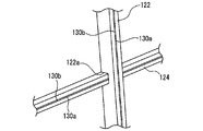
- FIG. 5 is a perspective view showing a state in which the intersection of the first reinforcing member 122 and the second reinforcing member 124 in FIG. 3 is viewed from the outside of the vehicle.
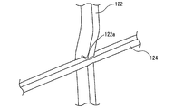
- FIG. 6 is a schematic view showing a state in which the first reinforcing member 122 and the second reinforcing member 124 are separated at the intersection shown in FIG. As described above, at the position of the intersection, the second reinforcing member 124 is located outside the vehicle with respect to the first reinforcing member 122. As shown in FIG.
- the thickness of the first reinforcing member 122 is smaller than the thickness of the groove portion 122a recessed from the outside of the vehicle toward the inside of the vehicle (that is, the portion of the first reinforcing member 122 that is not the groove portion 122a).
- a thickness reduction part is provided.
- the second reinforcing member 124 is inserted into the groove portion 122a. When the second reinforcing member 124 is inserted into the groove portion 122a at the intersection, the outer surfaces of the first reinforcing member 122 and the second reinforcing member 124 become substantially the same surface. Therefore, the vehicle outer surface of the first reinforcing member 122 and the second reinforcing member 124 can be joined to the back surface of the outer panel 110, or can be brought close to the back surface of the outer panel 110.
- the groove portion 122a provided in the first reinforcing member 122 is formed by providing an opening portion in the plate member 130 constituting the first reinforcing member 122.
- the groove portion 122a is formed by opening the plate member 130 before the plate member 130 is bent to form the first reinforcing member 122. Further, the groove portion 122a may be formed by processing the first reinforcing member 122 after the plate member 130 is bent to form the first reinforcing member 122.
- FIG. 7 is a perspective view showing a state in which the intersection shown in FIG. 5 is viewed from the inside of the vehicle.
- FIG. 8 is a perspective view showing a state in which the first reinforcing member 122 and the second reinforcing member 124 shown in FIG. 6 are separated and viewed from the inside of the vehicle.
- the ends 130a and 130b of the plate member 130 constituting the first reinforcing member 122 and the ends 130a and 130b of the plate material 130 forming the second reinforcing member 124 are both located inside the vehicle. There is.
- the first reinforcing member 122 and the second reinforcing member 124 intersect, a hole is provided in the plate member 130 constituting the first reinforcing member 122.
- the groove portion 122a is provided only on the first reinforcing member 122.
- the outer surface of the vehicle of the first reinforcing member 122 and the second reinforcing member 124 becomes substantially the same surface, so that the first reinforcing member 122 and the first reinforcing member 122
- the second reinforcing member 124 can be arranged adjacent to the back surface of the outer panel 110. Therefore, when an impact load is applied from the outside of the exterior panel 100, the impact load is dispersed and absorbed in the surface direction along the reinforcing member 120. Further, since the first reinforcing member 122 and the second reinforcing member 124 can be arranged adjacent to the back surface of the outer panel 110, the effect of improving the tension rigidity can also be obtained.
- FIG. 9 is a perspective view showing the intersection of the first reinforcing member 122 and the second reinforcing member 124.
- the first reinforcing member 122 is formed with a recess 122c by press working
- the second reinforcing member 122 is formed.
- the case where the recess 124c is formed in the reinforcing member 124 of the above by press working is shown as a related technique.
- the processing method is devised so that the concave portion 122c can be formed in the process of bending the plate material 130 in order to form the first reinforcing member 122, and various press dies and devices for processing are provided.
- various adjustments and corrections are made, or the plate material 130 is bent to form the first reinforcing member 122 having a rectangular cross section, and then a die is inserted into these hollow reinforcing members, and the like is pressed. Is done. Therefore, a very complicated process is required to form the recess 122c, and labor and time for designing and preparing the recess 122c are required.
- both the first reinforcing member 122 and the second reinforcing member 124 have recesses 122c and recesses.
- 124c is formed, the manufacturing process becomes complicated and the number of steps still increases.
- the groove portion 122a is formed by opening the plate member 130.
- a groove portion 122a is easily formed by forming an opening portion in the plate material 130 before bending the plate material 130 and then bending the plate material 130 as shown in FIG.
- the groove portion 122a is provided only on the first reinforcing member 122, and processing for providing the groove portion on the second reinforcing member 124 is unnecessary. Therefore, as compared with the configuration shown in FIG. 9, it is possible to provide the intersection in a simpler process, and the manufacturing cost is reduced.
- the first reinforcing member 122 and the second reinforcing member 124 are formed in both the first reinforcing member 122 and the second reinforcing member 124 as in the configuration example shown in FIG. 9, the first reinforcing member is formed at the position of the recesses 122c and 124c. Since the thickness of both the first reinforcing member 122 and the second reinforcing member 124 is reduced, the strength of both the first reinforcing member 122 and the second reinforcing member 124 is reduced at the position of the intersection. Therefore, when an impact load is applied from the outside of the vehicle, the first reinforcing member 122 and the second reinforcing member 124 may bend at the position of the intersection.
- the impact load is transmitted between the first reinforcing member 122 and the second reinforcing member 124 via the intersection. May become insufficient and the desired shock absorption performance may not be obtained.
- the second reinforcing member 124 is not provided with a groove at the intersection, and the second reinforcing member 124 is in the vehicle inside / outside direction (the direction connecting the outside of the vehicle and the inside of the vehicle, or The thickness of the outer panel 110 (in the direction perpendicular to the plate surface) has not decreased.
- Only the first reinforcing member 122 is provided with a groove portion 122a having a reduced thickness in the vehicle interior / external direction. Then, the shape of the groove portion 122a is made to match the shape of the cross section of the second reinforcing member 124, and the intersection portion is formed by fitting the second reinforcing member 124 into the groove portion 122a.
- the second reinforcing member 124 since the second reinforcing member 124 is not provided with the groove portion, the strength of the second reinforcing member 124 is not reduced by providing the groove portion. Further, as will be described later, the second reinforcing member 124 has a function of transmitting an impact load to the first reinforcing member 122 via the intersection. Since the second reinforcing member 124 is not provided with the groove portion, the second reinforcing member 124 is suppressed from being deformed at the position of the intersection. Therefore, the impact load is reliably transmitted from the second reinforcing member 124 to the first reinforcing member 122.
- the thickness of the second reinforcing member 124 in the vehicle internal and external directions does not have to be the same over the entire length in the longitudinal direction. Since the second reinforcing member 124 is fixed to the inner panel 135 at both ends thereof, the thickness of the fixed portion with the inner panel 135 changes in the inside and outside of the vehicle. On the other hand, the thickness of the second reinforcing member 124 in the inside / outside direction of the vehicle is uniform closer to the center than both ends. In other words, closer to the center than both ends of the second reinforcing member 124, the groove portion provided in the first reinforcing member 122 is not provided, and the thickness in the vehicle internal and external directions changes significantly.
- the uniform thickness of the second reinforcing member 124 in the vehicle internal and external directions means that the thickness at the intersection is not smaller than that on both sides of the intersection. Therefore, the uniform thickness of the second reinforcing member 124 in the vehicle internal and external directions means that the thickness of the second reinforcing member 124 is substantially constant over the total length of the second reinforcing member 124, and the thickness is increased from both ends to the center. It includes a configuration in which the thickness gradually increases to the maximum in the central portion, a configuration in which the thickness gradually decreases from both ends to the center, and the thickness becomes the minimum in the central portion.
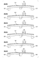
- FIG. 10 is a schematic view showing a configuration example in which the thickness of the second reinforcing member 124 in the vehicle internal / external direction is uniform in the present embodiment.
- FIG. 10 is a diagram schematically showing a cross section at a position of an intersection where the first reinforcing member 122 and the second reinforcing member 124 intersect, as in FIG. 4. Note that, unlike FIG. 4, in FIG. 10, the plate thickness of the plate member 130 constituting the first reinforcing member 122 and the second reinforcing member 124 is not shown. Further, in FIG. 10, the illustration of the inner panel 135 is omitted.
- the thickness of the second reinforcing member 124 changes gradually with respect to the total length of the second reinforcing member 124 in the vehicle internal and external directions (configuration examples 1 and 2), and the thickness of the second reinforcing member 124 changes.
- An example (configuration examples 3 to 6) in which the thickness is not reduced as compared to both sides of the intersection at the position of the intersection is shown.
- Example 2 is shown.
- the thickness of the second reinforcing member 124 does not change according to the position of the intersection. Includes a configuration example of.
- the roles played by the first reinforcing member 122 and the second reinforcing member 124 are different.
- the first reinforcing member 122 and the second reinforcing member 124 have different deformation resistances to an impact load from the outside of the vehicle even if they have the same thickness due to the difference in the length and the degree of curvature in the exterior panel 100.
- the exterior panel 100 is a door panel
- the first reinforcing member 122 is shorter than the second reinforcing member 124 because the door panel is usually horizontally elongated in the horizontal direction.
- the first reinforcing member 122 and the second reinforcing member 124 are considered as beams having both ends fixed, the first reinforcing member 122 having a shorter length is the second reinforcing member having a longer length.
- the deformation resistance when a load is applied to the center in the longitudinal direction is higher than that of 124. Therefore, in order to receive the impact load and absorb the impact, the first reinforcing member 122 is more suitable than the second reinforcing member 124.
- the first reinforcing member 122 may be subjected to an impact load from the outside of the vehicle. Since the axial force of compression acts in the longitudinal direction, the deformation resistance to the load becomes high.
- the second reinforcing member 124 having less curvature when an impact load is applied from the outside of the vehicle, the axial force of compression hardly acts in the longitudinal direction. Therefore, the first reinforcing member 122 is superior to the second reinforcing member 124 in impact resistance performance because the axial force of compression acts on the first reinforcing member 122 and the deformation resistance tends to be higher when an impact load is applied.
- the automobile door is configured so that the length in the vehicle length direction is longer when the vehicle length direction and the vehicle height direction are compared except for the window frame part. It is often done. When both ends of a member having the same cross-sectional shape are supported, the longer member is more likely to be deformed when a load is applied to the center. Therefore, comparing the second reinforcing member 124 that crosses the vehicle length direction and the first reinforcing member 122 that crosses the vehicle height direction, the first reinforcing member 122 that crosses the vehicle height direction in the case of the same cross-sectional shape. Is stronger.
- the shape in the vehicle height direction of the cross section perpendicular to the vehicle length direction is in the vehicle length direction of the cross section perpendicular to the vehicle height direction.
- the curvature that the outside in the vehicle width direction is convex is larger than the shape.
- the first reinforcing member 122 can withstand a larger load than the second reinforcing member 124, and has higher impact resistance.
- the first reinforcing member 122 extending in the vehicle height direction has higher shock absorbing performance than the second reinforcing member 124 extending in the vehicle length direction.
- the impact load in the vehicle width direction (side collision load) is mainly absorbed by the impact absorbing member in the vehicle height direction. Therefore, in order to improve the impact absorption performance more efficiently, it is better to increase the bending rigidity of the first reinforcing member 122 than that of the second reinforcing member 124.
- the second reinforcing member 124 in the vehicle length direction is the first reinforcement in the vehicle height direction. It is arranged on the outside of the vehicle (outer panel 110 side) from the member 122. As a result, no matter which part on the outside of the automobile door is loaded with the impact load, the second reinforcing member 124 in the vehicle length direction can transmit the impact load to the first reinforcing member 122 in the vehicle height direction. Finally, the impact load can be absorbed by the first reinforcing member 122 in the vehicle height direction.
- the impact absorption performance of the automobile door is improved by reducing the bending rigidity of the second reinforcing member 124.
- the effect of is smaller than the effect of reducing the bending rigidity of the first reinforcing member 122. Since the bending rigidity is reduced when the cross section of the reinforcing member is reduced or the thickness of the constituent plate material is reduced, the bending rigidity of the first reinforcing member 122 is relatively large, and the bending of the second reinforcing member 124 is performed.
- the tension rigidity of the outer panel 110 can be improved by forming both the first reinforcing member 122 and the second reinforcing member 124 arranged vertically and horizontally along the inside of the outer panel 110.
- the first reinforcing member 122 which has a high deformation resistance when a load is applied inward in the vehicle width direction and is more suitable for shock absorption, is made thicker than the second reinforcing member 124 to increase the bending rigidity.
- the deformation resistance of the first reinforcing member 122 can be further increased, and shock absorption can be performed more effectively.
- the first reinforcing member 122 which is excellent in both dimensional and shape in terms of impact resistance, mainly absorbs the impact load. be able to.
- the term "thicker" than the second reinforcing member 124 means that the first reinforcing member 122 is a member having a cross section (cross section) orthogonal to the longitudinal direction of the first reinforcing member 122 or the second reinforcing member 124. It means that the region of the second reinforcing member 124 is included in the region of the first reinforcing member 122 with respect to the region inside the contour of the above. For example, when the cross section of the first reinforcing member 122 and the second reinforcing member 124 has a hollow rectangular shape as shown in FIG. 2, the first reinforcing member 122 is "thicker" than the second reinforcing member 124. With respect to the dimensions represented by D and H shown in FIG. 2, at least one of the dimensions of the first reinforcing member 122 is larger than that of the second reinforcing member 124, and the other is equal to or larger than that of the second reinforcing member 124. Say something.
- the second reinforcing member 124 has a function of transmitting the impact load applied to the exterior panel 100 from the outside to the first reinforcing member 122. Therefore, at the intersection, the second reinforcing member 124 is located outside the vehicle rather than the first reinforcing member 122.
- the impact load is first transmitted from the outer panel 110 to the reinforcing member 120, and the reinforcing member 120 arranged adjacent to the outer panel 110 receives the impact load.
- the second reinforcing member 124 is arranged outside the vehicle at the intersection, the impact load is applied between the plurality of adjacent first reinforcing members 122.
- the impact load is transmitted from the outer panel 110 to the second reinforcing member 124, and is transmitted to the first reinforcing member 122 while the second reinforcing member 124 is deformed.
- the first reinforcing member 122 has higher flexural rigidity than the second reinforcing member 124 from the viewpoint of cross-sectional dimensions, and an impact load is applied from the viewpoint of the length of the member and the curvature shape in which the outer side in the vehicle width direction is convex. In this case, the deformation resistance is further increased, so that the impact load can be effectively absorbed by the first reinforcing member 122.
- the reinforcing member 120 when the reinforcing member 120 is formed by intersecting the two reinforcing members, the reinforcing member having the lower bending rigidity is arranged on the outside of the vehicle, and the reinforcing member having the higher bending rigidity is arranged on the inside of the vehicle. Will be done.
- the impact load when an impact load is applied from the outside of the vehicle, the impact load is transmitted from the reinforcing member having the lower bending rigidity to each of the plurality of reinforcing members having the higher bending rigidity, and the plurality of reinforcing members having the higher bending rigidity.
- the impact load can be reliably absorbed by the reinforcing member.
- the exterior panel 100 which is lighter in weight while maintaining the required strength.
- the first reinforcing member 122 is arranged in the vertical direction (vehicle height direction) and the second reinforcing member 124 is arranged in the horizontal direction (vehicle length direction).
- the embodiment is not limited to this, and the first reinforcing member 122 may be arranged in the horizontal direction and the second reinforcing member 124 may be arranged in the vertical direction.
- the first reinforcing member 122 is arranged in the horizontal direction. It is preferable that the second reinforcing member 124 is arranged in the vertical direction. Further, the first reinforcing member 122 and the second reinforcing member 124 may be arranged obliquely with respect to the horizontal direction or the vertical direction and may intersect with each other.
- the groove portion 122a in the first reinforcing member 122 By the way, by providing the groove portion 122a in the first reinforcing member 122, the thickness of the first reinforcing member 122 in the direction from the outside of the vehicle to the inside of the vehicle is reduced at the position of the groove portion 122a (thickness reduction portion). Therefore, if the groove portion 122a is simply provided and the first reinforcing member 122 and the second reinforcing member 124 are crossed with each other, the strength of the first reinforcing member 122 is lowered at the position of the groove portion 122a.
- the first reinforcing member 122 is arranged so that the vertical width of the groove portion 122a becomes narrow when an impact load is applied, and the groove portion 122a sandwiches the second reinforcing member 124. By doing so, the decrease in strength due to the provision of the groove portion 122a is suppressed.
- 11 and 12 are schematic views for explaining the structure of the intersection.
- 11 and 12 show a state in which the intersection is viewed from the longitudinal direction of the second reinforcing member 124, and the second reinforcing member 124 shows a cross section.
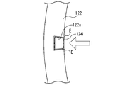
- FIG. 11 shows a state in which an impact load is not applied to the first reinforcing member 122 and the second reinforcing member 124.
- FIG. 12 shows a state in which an impact load is applied to the first reinforcing member 122 and the second reinforcing member 124 from the outside of the vehicle in the direction of the arrow.
- the cross section of the first reinforcing member 122 has a rectangular shape as described in FIG. 2, and one side thereof has a long side of about 16 mm and a short side of about 10 mm.
- the cross section of the second reinforcing member 124 has a square shape with a side of about 8 mm.
- the plate thickness of the first reinforcing member 122 and the second reinforcing member 124 is about 0.8 mm.
- the shape and thickness of the cross section of the first reinforcing member 122 and the second reinforcing member 124 are not limited to these.
- the cross section of the second reinforcing member 124 may also have a rectangular shape.
- the shape of the groove portion 122a when the intersection is viewed from the longitudinal direction of the second reinforcing member 124 corresponds to the shape of the cross section of the second reinforcing member 124. That is, the shape of the groove portion 122a is the same rectangular shape as the outer rectangular shape of the cross section of the second reinforcing member 124. Then, preferably, the second reinforcing member 124 is fitted in the groove portion 122a.
- the second reinforcing member 124 that has received the impact load is deformed and the second reinforcing member 124 is deformed.
- the reinforcing member 124 of the above transmits the impact load to the plurality of first reinforcing members 122 through the intersection while absorbing the impact load.
- the first reinforcing member 122 absorbs an impact load while deforming inside the vehicle.
- the first reinforcing member 122 absorbs the impact load while deforming inside the vehicle.
- the shape of the first reinforcing member 122 which was originally curved following the outer panel 110, is deformed in the direction of returning to a straight line.
- the groove portion 122a is also deformed.
- the groove portion 122a is arranged toward the outside of the vehicle, when the curvature of the first reinforcing member 122 is deformed in the direction of returning to a straight line, the groove portion 122a is deformed in the direction of narrowing the width in the vertical direction.
- the upper and lower end faces of the groove portion 122a sandwich the second reinforcing member 124.
- the distance between the upper and lower edges E of the groove portion 122a is narrowed, and the edge E sandwiches the bottom surface of the second reinforcing member 124, so that the groove portion 122a is secondly reinforced.
- the member 124 is sandwiched.
- the first reinforcing member 122 is deformed while sandwiching the second reinforcing member 124 between the groove portions 122a, so that the first reinforcing member 122 absorbs the impact load without causing breakage or the like at the position of the groove portion 122a.
- the decrease in strength of the first reinforcing member 122 due to the provision of the groove portion 122a is compensated by the groove portion 122a sandwiching the second reinforcing member 124.
- the groove portion 122a sandwiches the second reinforcing member 124, so that the strength of the first reinforcing member 122 is equivalent to that in the case where the groove portion 122a is not provided. Therefore, the strength of the first reinforcing member 122 does not decrease due to the provision of the groove portion 122a. Since the strength of the first reinforcing member 122 does not decrease due to the provision of the groove portion 122a, the first reinforcing member 122 is deformed so as to bend at the position of the groove portion 122a when an impact load is applied. Is suppressed.
- the first reinforcing member 122 is deformed in the direction in which the curvature returns to a straight line as a whole, so that the impact load is effectively absorbed.
- the groove portion 122a sandwiches the second reinforcing member 124 and the first reinforcing member 122 is deformed in the direction in which the curvature returns to a straight line as a whole, the second reinforcing member 122 is sandwiched by the upper and lower edges E of the groove portion 122a.
- a compressive force is applied to the bottom surface of the reinforcing member 124 in the direction along the longitudinal direction of the first reinforcing member 122.
- the compressive force is maintained only while maintaining the surface shape of the bottom surface of the second reinforcing member 124, or with only a slight amount of bending outside the surface.
- the axial force of compression in the longitudinal direction of the first reinforcing member 122 can be sufficiently transmitted above and below the groove portion 122a.
- the force acting on the first reinforcing member 122 differs from the position of 1/2 of the thickness of the first reinforcing member 122 (indicated by the alternate long and short dash line in FIG. 12).
- the groove portion 122a is provided in the region of the first reinforcing member 122 that receives the compressive force. Become. Since the second reinforcing member 124 is inserted into the groove portion 122a, the second reinforcing member 124 receives the compressive force. Therefore, the compressive force is transmitted through the second reinforcing member 124 in the longitudinal direction of the region outside the vehicle from the alternate long and short dash line of the first reinforcing member 122. Therefore, as described above, the groove portion 122a is provided.
- the impact absorption capacity equivalent to that in the case where the groove portion 122a is not provided in the first reinforcing member 122 can be obtained without reducing the strength of the first reinforcing member 122. Further, if the depth of the groove portion 122a is 1 ⁇ 2 or less of the thickness of the first reinforcing member 122, no tensile force acts on the bottom of the groove portion 122a, so that a crack occurs at the bottom of the groove portion 122a. There is no.
- the bottom of the groove portion 122a is located inside the vehicle from the position of the alternate long and short dash line in FIG.
- the region that receives the tensile force in the longitudinal direction decreases in the thickness direction of the first reinforcing member 122.
- Tensile force is concentrated in a narrow range.
- the depth of the groove portion 122a is preferably 1/2 or less of the thickness of the first reinforcing member 122. In other words, in FIG. 12, it is preferable that the position of the bottom of the groove portion 122a coincides with the position of the alternate long and short dash line, or is outside the vehicle from the position of the alternate long and short dash line.
- the groove portion 122a is deformed when an impact load is applied, and the groove portion 122a sandwiches the second reinforcing member 124. Therefore, at the intersection, the first reinforcing member 122 and the second reinforcing member 122 are sandwiched. 124 is tightly coupled. Therefore, the impact load is reliably transmitted from the second reinforcing member 124 to the first reinforcing member 122 and absorbed. Further, by transmitting the compressive force in the longitudinal direction of the first reinforcing member 122 to the upper and lower sides of the groove portion 122a by the second reinforcing member 124, shock absorption equivalent to the case where the groove portion 122a is not provided in the first reinforcing member 122 is absorbed. You can get the ability.
- the second reinforcing member 124 when an impact load is applied to the exterior panel 100 from the outside of the vehicle, if the first reinforcing member 122 and the second reinforcing member 124 are separated by the impact at the intersection, the second reinforcing member The impact load is not transmitted from 124 to the first reinforcing member 122, and the impact absorption performance cannot be maintained.
- the second reinforcing member 124 when the second reinforcing member 124 is inserted into the groove portion 122a facing the inside of the vehicle, when the curvature of the first reinforcing member 122 is deformed in the direction of returning to a straight line, the vertical width of the groove portion 122a is widened. Therefore, at the intersection, the first reinforcing member 122 and the second reinforcing member 124 are easily separated.
- the groove portion 122a faces the outside of the vehicle, when an impact load is applied from the outside of the vehicle, the vertical width of the groove portion 122a is narrowed, and the upper and lower end faces of the groove portion 122a are second.
- the reinforcing member 124 is sandwiched. Therefore, at the intersection, the first reinforcing member 122 and the second reinforcing member 124 are firmly connected, and the separation of the first reinforcing member 122 and the second reinforcing member 124 is suppressed. As a result, the impact load is reliably transmitted from the second reinforcing member 124 to the first reinforcing member 122, and the impact load is reliably absorbed.
- the second reinforcing member 124 may not be fitted into the groove portion 122a, and there may be a gap between the second reinforcing member 124 and the groove portion 122a. Even with such a configuration, when an impact load is applied from the outside of the exterior panel 100, the width of the groove portion 122a in the vertical direction becomes narrower, so that the second reinforcing member 124 can be sandwiched by the groove portion 122a. In other words, the groove portion 122a does not have to be fitted with the second reinforcing member 124.
- the ends 130a and 130b of the plate members 130 constituting the first reinforcing member 122 are on the inner surface of the vehicle (the above-mentioned top surface and the second surface). Have been placed.
- the ends 130a and 130b of the plate member 130 constituting the second reinforcing member 124 are also arranged on the inner surface of the vehicle (the second surface described above).
- the ends 130a and 130b are the outer surfaces of the vehicle (the bottom surface and the first surface described above) so as to face the outer panel 110 as in the example of the second reinforcing member 124 shown in FIGS. 13 and 14. It may be arranged in.
- the ends 130a and 130b of the plate member 130 constituting the second reinforcing member 124 are located on the outside of the vehicle, the ends 130a and 130b do not exist on the inside of the vehicle, so that when the groove 122a is deformed, the second The inside of the vehicle of the reinforcing member 124 is less likely to be crushed. Therefore, when an impact load is applied, the groove portion 122a reliably sandwiches the second reinforcing member 124, and the second reinforcing member 124 is less likely to come off from the groove portion 122a.
- FIGS. 11 and 12 are schematic views showing a case where the end 130a and the end 130b of the second reinforcing member 124 are located on the outside of the vehicle, and are the second ones as in FIGS. 11 and 12.
- FIG. 13 shows a state in which an impact load is not applied to the first reinforcing member 122 and the second reinforcing member 124.
- FIG. 14 shows a state in which an impact load is applied to the first reinforcing member 122 and the second reinforcing member 124 from the outside of the vehicle in the direction of the arrow, and the groove portion 122a sandwiches the second reinforcing member 124. It shows a state in which the end portion 130a and the end portion 130b of the second reinforcing member 124 overlap.
- the ends 130a and 130b of the second reinforcing member 124 are located on the outer side of the vehicle and the ends 130a and 130b of the second reinforcing member 124 overlap, the ends 130a and the ends 130a and the ends 130b overlap.
- the width of the surface (bottom surface) where the 130b is located becomes narrow, but the width of the surface (top surface) facing the surface where the end 130a and the end 130b are located, that is, the surface inside the vehicle, hardly changes, and the second The cross section of the reinforcing member 124 of the above approaches a pseudo-trapezoidal shape.
- the shape of the groove portion 122a seen from the longitudinal direction of the second reinforcing member 124 also approaches a trapezoidal shape in a pseudo manner. That is, both the cross-sectional shape of the second reinforcing member 124 and the shape of the groove portion 122a approach the trapezoidal shape in a pseudo manner. Therefore, as shown in FIGS. 13 and 14, when the end 130a and the end 130b of the second reinforcing member 124 are located outside the vehicle, the end 130a and the end 130b overlap.
- the width of the inner surface (top surface) of the second reinforcing member 124 hardly changes, and both the cross-sectional shape of the second reinforcing member 124 and the shape of the groove 122a are directed toward the outside of the vehicle.
- the second reinforcing member 124 is less likely to come off from the groove portion 122a in which the distance between the upper and lower edges E is narrowed because the width approaches the trapezoidal shape. Therefore, considering that the end portion 130a and the end portion 130b overlap, it is preferable that the end portion 130a and the end portion 130b of the second reinforcing member 124 are located on the outer side of the vehicle.
- the end 130a and the end 130b of the second reinforcing member 124 are provided with the curved portion 132 described later, the overlap as shown in FIG. 14 is suppressed, so that the upper and lower end faces of the groove 122a are formed.
- the axial force of compression in the longitudinal direction of the first reinforcing member 122 is transmitted to the upper and lower sides of the groove portion 122a via the second reinforcing member 124, so that the first reinforcing member It is possible to obtain the same impact absorption capacity as when the groove portion 122a is not provided in the 122.
- the end 130a and the end 130b of the second reinforcing member 124 are in contact with each other in a state where the second reinforcing member 124 is assembled to the exterior panel 100, but processing accuracy, dimensional tolerance, etc. For this reason, a gap may occur between the end portion 130a and the end portion 130b.
- a gap may occur between the end 130a and the end 130b.
- the groove portion 122a is deformed by the impact load and the distance between the upper and lower edges E becomes narrower, and when the outer side of the vehicle of the second reinforcing member 124 is sandwiched, the end portions 130a and the end portions 130b are formed as shown in FIG. Until the gap between them is closed, the transmission of the axial force of compression in the longitudinal direction of the first reinforcing member 122 through the second reinforcing member 124 is not sufficient, that is, the longitudinal direction of the first reinforcing member 122.
- the axial force of the compression is not sufficiently transmitted to the upper and lower sides of the groove portion 122a via the second reinforcing member 124, and the shock absorbing capacity may be temporarily reduced during that time.
- the end portion 130a and the end portion 130b are surely in contact with each other, the second reinforcing member 124 is less likely to be crushed, and the second reinforcing member 124 is not easily crushed.
- the member 124 is less likely to come off from the first reinforcing member 122. Therefore, when the ends 130a and 130b are located inside the vehicle of the second reinforcing member 124, if the end 130a and the end 130b are provided with the curved portion 132 described later, the end 130a and the end 130a It is most preferable because the end portion 130b is surely in contact with the end portion 130b and the second reinforcing member 124 is less likely to be crushed.
- the configuration of the curved portion 132 will be described in detail later.
- 16 and 17 are schematic views showing variations in the structure of the intersection. 16 and 17 show a cross section of the second reinforcing member 124 and a state in which the intersection is viewed from the longitudinal direction of the second reinforcing member 124, similarly to FIGS. 11 and 12.
- FIGS. 16 and 17 show an example in which the cross section of the second reinforcing member 124 has a trapezoidal shape.
- the width of the bottom surface of the second reinforcing member 124 is narrower than the width of the top surface.
- FIG. 16 shows a state in which an impact load is not applied to the first reinforcing member 122 and the second reinforcing member 124.
- FIG. 17 shows a state in which an impact load is applied to the first reinforcing member 122 and the second reinforcing member 124 from the outside of the vehicle in the direction of the arrow.
- the curvature of the first reinforcing member 122 is deformed in the direction of returning to a straight line, the distance between the upper and lower edges E of the groove portion 122a is narrowed, and the groove portion 122a is formed.
- the second reinforcing member 124 is sandwiched.
- the cross section of the second reinforcing member 124 has a trapezoidal shape and a wedge-shaped shape that tapers toward the outside of the vehicle, when the groove portion 122a is deformed and the second reinforcing member 124 is sandwiched. , The second reinforcing member 124 is more difficult to come off from the groove portion 122a.
- the first reinforcing member 122 and the second reinforcing member 124 are more firmly coupled to each other when an impact load is applied, and the first reinforcing member 122 and the second reinforcing member 124 are separated from each other. It is suppressed that it is stored. Therefore, the impact load is reliably transmitted from the second reinforcing member 124 to the first reinforcing member 122, and the impact load is reliably absorbed.
- FIGS. 18 and 19 are examples in which the cross section of the second reinforcing member 124 is trapezoidal, as in FIGS. 16 and 17, but the shape of the groove 122a is changed to the shape of the cross section of the second reinforcing member.
- An example of a trapezoidal shape is shown.
- the shape of the groove portion 122a is substantially along the cross section of the second reinforcing member 124. There may be a slight gap between the groove portion 122a and the cross section of the second reinforcing member 124.
- FIG. 18 shows a state in which an impact load is not applied to the first reinforcing member 122 and the second reinforcing member 124.
- FIG. 19 shows a state in which an impact load is applied to the first reinforcing member 122 and the second reinforcing member 124 from the outside of the vehicle in the direction of the arrow.
- the curvature of the first reinforcing member 122 is deformed in the direction of returning to a straight line, and the distance between the upper and lower edges E of the groove portion 122a becomes narrower.
- the groove portion 122a sandwiches the second reinforcing member 124.
- the shape of the groove portion 122a is a trapezoidal shape that follows the shape of the cross section of the second reinforcing member 124, the groove portion 122a is deformed as compared with the configurations of FIGS. 16 and 17.
- the axial force of compression in the longitudinal direction of the first reinforcing member 122 is moved up and down of the groove portion 122a via the second reinforcing member 124. Since it is transmitted to the groove portion 122a, the groove portion 122a more reliably sandwiches the second reinforcing member 124. Therefore, at the intersection, the first reinforcing member 122 and the second reinforcing member 124 are more firmly coupled to each other when an impact load is applied, and the first reinforcing member 122 and the second reinforcing member 124 are separated from each other. It is suppressed that it is stored. Therefore, the impact load is reliably transmitted from the second reinforcing member 124 to the first reinforcing member 122, and the impact load is reliably absorbed.
- the first reinforcing member 122 is in a direction in which the curvature becomes stronger.
- a method may be used in which a portion having a rectangular cross section having the same dimensions as the width is partially provided, the second reinforcing member 124 is inserted into the groove portion 122a from the portion, and then the portion is slid to the position of the intersection.
- the groove portion 122a sandwiches the second reinforcing member 124, so that a force acts on the second reinforcing member 124 in the direction of being crushed in the vertical direction.
- the ends 130a and 130b of the second reinforcing member 124 come into contact with each other and come into close contact with each other, the shape of the cross section of the second reinforcing member 124 is maintained, so that the groove portion 122a presses the second reinforcing member 124. It can be reliably sandwiched, and the compressive force in the longitudinal direction on the outside of the vehicle of the first reinforcing member 122 can be transmitted more reliably.
- the groove portion 122a sandwiches the second reinforcing member 124
- the end portions 130a and 130b of the second reinforcing member 124 do not come into contact with each other, and the end portions 130a and the end portion 130b overlap. Then, the shape of the cross section of the second reinforcing member 124 collapses.
- the second reinforcing member 124 becomes thinner than when the end portions 130a and 130b are in contact with each other. Therefore, since the area of the cross section of the second reinforcing member 124 becomes smaller, the groove portion 122a cannot reliably sandwich the second reinforcing member 124, and the longitudinal length of the first reinforcing member 122 on the outside of the vehicle. The compressive force in the direction cannot be sufficiently transmitted, and the second reinforcing member 124 tends to come off from the groove portion 122a.
- the groove portion 122a when the groove portion 122a is deformed, the end portions 130a and 130b are brought into contact with each other to prevent the cross-sectional shape of the second reinforcing member 124 from collapsing, and the groove portion 122a is the second reinforcing member 124. It is necessary to be able to securely sandwich.
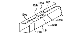
- FIG. 20 shows an example in which curved portions 132 are provided at the ends 130a and 130b of the plate member 130 constituting the second reinforcing member 124 at the position of the intersection.
- FIG. 20 is a view showing a state in which the intersection is viewed from the inside of the vehicle, as in FIG. 8, and is a perspective view showing a state in which the first reinforcing member 122 and the second reinforcing member 124 are separated at the intersection. Is.
- the ends 130a and 130b of the second reinforcing member 124 arranged toward the inside of the vehicle have a curved portion 132 in a range D in which the second reinforcing member 124 is inserted into the groove portion 122a of the first reinforcing member 122.
- the curved portion 132 is provided over a wider range than the range D in which the second reinforcing member 124 is inserted into the groove portion 122a of the first reinforcing member 122.
- the curved portion 132 may be provided in the vicinity of the range D outside the range D in which the second reinforcing member 124 is inserted into the groove portion 122a of the first reinforcing member 122. Even if the position where the curved portion 132 is provided is outside the range D, the same effect as providing the curved portion 132 in the range D can be obtained by arranging the curved portion 132 close to the range D, that is, the intersection. ..
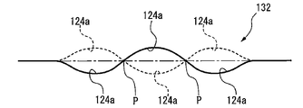
- 21 and 22 are perspective views showing in detail the curved portion 132 provided in the second reinforcing member 124.
- the curved portion 132 is formed by forming concave surfaces 124a on the front and back surfaces of the plate material 130 at the ends 130a and 130b of the plate material 130.
- the positions of the concave surfaces 124a are deviated from each other between the curved portion 132 provided at the end portion 130a and the curved portion 132 provided at the end portion 130b.
- FIG. 23 is a schematic view showing the positional relationship between the position of the concave surface 124a provided on the end portion 130a and the position of the concave surface 124a provided on the end portion 130b.
- FIG. 23 schematically shows a state in which the curved portion 132 is viewed from a direction orthogonal to the longitudinal direction of the second reinforcing member 124 and along the top surface of the second reinforcing member 124.
- the solid line shows the shape of the curved portion 132 provided at the end portion 130a
- the broken line shows the shape of the curved portion 132 provided at the end portion 130b.
- the curved portion 132 of the end portion 130a is composed of two concave surfaces 124a provided on the front side and one concave surface 124a provided on the back side between the two concave surfaces 124a on the front side.
- the curved portion 132 of the end portion 130b is composed of two concave surfaces 124a provided on the back side and one concave surface 124a provided on the front side between the two concave surfaces 124a on the back side.
- the groove portion 122a of the first reinforcing member 122 is deformed and the second reinforcing member 124 is deformed.
- the end portion 130a and the end portion 130b come into contact with each other. Therefore, when the groove portion 122a is deformed, it is possible to prevent the end portion 130a and the end portion 130b from overlapping each other and collapsing the cross-sectional shape of the second reinforcing member 124.
- the second reinforcing member 124 is securely sandwiched by the groove portion 122a, so that the second reinforcing member 124 does not come off from the groove portion 122a when an impact load is applied, and the impact load is the second.
- the reinforcing member 124 is reliably transmitted to the first reinforcing member 122, and the compressive force of the first reinforcing member 122 in the longitudinal direction on the outside of the vehicle is transmitted to the first reinforcing member 122 via the second reinforcing member 124. It is surely transmitted inside. Therefore, the impact load is reliably absorbed by the first reinforcing member 122 and the second reinforcing member 124.
- FIG. 23 shows an example in which three concave surfaces 124a are provided on each of the end portion 130a and the end portion 130b, but the number of concave surfaces 124a is not limited to this.
- the shape of the curved portion 132 provided at the end portion 130a and the end portion 130b a bulge due to the concave surface 124a of the second reinforcing member 124 is formed inside and outside the top surface of the second reinforcing member 124.
- the shape of the curved portion 132 is not limited to this. For example, as shown in FIG.
- the bulge of the curved portion 132 due to the concave surface 124a may be formed only inside the surface on which the end portion 130a and the end portion 130b of the second reinforcing member 124 are formed.
- the bulge due to the concave surface 124a is formed only inside the surface on which the end 130a and the end 130b of the second reinforcing member 124 are formed, so that the curved portion 132 is formed in the groove portion of the first reinforcing member 122.
- the second reinforcing member 124 When the second reinforcing member 124 is arranged in the range D to be inserted into the groove portion 122a, the second reinforcing member 124 can be fitted into the groove portion 122a without interfering with the bottom of the groove portion 122a and the bulge of the curved portion 132, which is preferable.
- FIG. 25 is a perspective view showing a state in which the configuration shown in FIG. 20 is viewed from the outside of the vehicle.
- an impact load is applied from the outside of the exterior panel 100.
- It is a schematic diagram which shows the loaded state.
- the curved portions 132 at the ends 130a and 130b it is possible to prevent the ends 130a and 130b from overlapping each other when the groove portion 122a is deformed and the second reinforcing member 124 is sandwiched. NS. Therefore, as shown in FIG. 25, when the groove portion 122a is deformed, the second reinforcing member 124 is not crushed and the cross-sectional shape is not collapsed, and the groove portion 122a securely sandwiches the second reinforcing member 124. ..
- the ends 130a and 130b of the plate member 130 constituting the second reinforcing member 124 are located inside the vehicle, when the groove portion 122a is deformed by the impact load, the groove portion 122a is deformed.
- the inside of the vehicle of the second reinforcing member 124 is less likely to be crushed because the curved portion 132 is provided.
- the outer side of the second reinforcing member 124 has a shape that is not easily crushed because the ends 130a and 130b do not exist in the first place.
- both the inside and outside of the vehicle of the second reinforcing member 124 are less likely to be crushed, and the cross-sectional shape of the second reinforcing member 124 is suppressed from collapsing. Further, since the second reinforcing member 124 is not easily crushed at the intersection, the deformation of the first reinforcing member 122 at the position of the groove portion 122a is surely suppressed. Therefore, the impact load is surely absorbed.
- the curved portions 132 are provided at the ends 130a and 130b, but the ends are provided on the outside of the vehicle.
- the curved portions 132 may be provided at the end portions 130a and 130b. Even in this case, when the groove portion 122a is deformed to sandwich the second reinforcing member 124, the outside of the vehicle provided with the curved portion 132 is less likely to be crushed. Therefore, the deformation of the first reinforcing member 122 is surely suppressed at the position of the groove portion 122a, and the impact load is surely absorbed.
- the first reinforcing member 122 is also provided with curved portions 132 at the ends 130a and 130b.
- the shape of the first reinforcing member 122 which has been curved following the outer panel 110, is deformed in the direction of returning to a straight line.
- the ends 130a and 130b of the first reinforcing member 122 are located inside the vehicle. If so, the ends 130a and 130b are affected in a direction closer to each other.
- the end portions 130a and 130b may overlap with each other for the first reinforcing member 122, and if the overlap occurs, the first reinforcing member 122 may overlap.
- the cross-sectional shape of the reinforcing member 122 may collapse and the impact load may not be sufficiently absorbed. That is, it is preferable that the first reinforcing member 122 is also provided with curved portions 132 at the ends 130a and 130b. Further, the curved portion 132 of the first reinforcing member 122 is preferably located at the intersection or in the vicinity of the intersection.
- the first reinforcing member 122 transmits an impact load from the second reinforcing member 124 at the intersection and the cross-sectional shape does not collapse at the position of the intersection.
- the curved portion 132 of the first reinforcing member 122 may be located at the center or a vicinity of the center in the longitudinal direction of the first reinforcing member 122.
- the present invention can be applied to the front door and the rear door of an automobile. Further, the present invention can be applied not only to doors arranged on the side of an automobile but also on doors arranged on the rear of an automobile.
- a door also referred to as a tailgate
- the inner panel of such a door is arranged in a direction intersecting the command length direction of the automobile.
- the vehicle length direction described in the embodiment may be read as the vehicle width direction
- the vehicle width direction may be read as the vehicle length direction.
- FIG. 26 comprises the exterior panel 100 shown in FIG. 3, and the structure of the intersection is shown in the conventional example shown in FIG. 9, the configuration of FIGS. 5 to 8 of the present embodiment (invention example 1), and the view of the present embodiment.
- FIG. 5 is a characteristic diagram obtained by simulation of the relationship between the load applied to the indenter and the stroke when the pole-shaped indenter is pressed against the exterior panel 100 in each of the 20 configurations (Invention Example 2). This evaluation assumes the case where a structure such as a utility pole collides with the door panel of the vehicle from the side, and the shape of the indenter is a pole shape assuming the utility pole.
- the pole-shaped indenter is a cylinder with a radius of 150 mm (diameter 300 mm), and is a pole-shaped indenter that stands upright in the vertical direction between the two first reinforcing members 122 in the center of FIG. 3 assuming a collision with a utility pole.
- the load and stroke when the indenter was pressed were simulated.
- invention example 1 in which the curved portions 132 are not provided at the ends 130a and 130b of the second reinforcing member 124, and the curved portions 132 are provided at the ends 130a and 130b of the second reinforcing member 124.
- Invention Example 2 almost the same results as those of the conventional example were obtained. Therefore, according to Invention Example 1 and Invention Example 2, the structure of the intersection can be made simpler than that of the conventional example shown in FIG. 9, and the shock absorbing capacity equivalent to that of the conventional example can be obtained.
- the plate material 130 is provided only on the first reinforcing member 122 without providing the structure of the intersection having a complicated shape by press working as in the conventional example.
- the groove portion 122a formed by opening the hole is provided and the second reinforcing member 124 is inserted, the same shock absorbing ability as in the conventional example can be obtained.
- the groove portion 122a is provided, so that the thickness of the first reinforcing member 122 in the vehicle internal and external directions is reduced, but the groove portion 122a becomes the second reinforcing member when an impact load is applied. It is considered that one of the reasons is that the strength of the first reinforcing member 122 is not lowered due to the provision of the groove portion 122a because the 124 is sandwiched.
- the structure of the crossing portion is further simplified and the manufacturing process is further simplified. And the desired shock absorption capacity can be obtained.
- the present invention in the skeleton structure of an automobile exterior panel in which members constituting the skeleton intersect with each other, it is possible to provide a skeleton structure of an automobile exterior panel that can simplify the manufacturing process and reliably absorb an impact load. ..
- Exterior panel 110 Outer panel 120 Reinforcing member 122 First reinforcing member 122a Groove 124 Second reinforcing member 130 Plate material 130a, 130b End part 132 Curved part
Landscapes
- Engineering & Computer Science (AREA)
- Mechanical Engineering (AREA)
- Textile Engineering (AREA)
- Body Structure For Vehicles (AREA)
Abstract
Description
本願は、2020年3月24日に、日本に出願された特願2020-053280号、及び2020年3月24日に、日本に出願された特願2020-053293号に基づき優先権を主張し、その内容をここに援用する。
110 アウタパネル
120 補強部材
122 第1の補強部材
122a 溝部
124 第2の補強部材
130 板材
130a,130b 端部
132 湾曲部
Claims (24)
- 板状のアウタパネルと、
前記アウタパネルより車両内側に配置される長尺状の複数の第1の部材と、
複数の前記第1の部材と交差する長尺状の第2の部材と、を備え、
複数の前記第1の部材のそれぞれは、前記アウタパネルの板面に沿った第1の方向に延在し、長手方向の一部分において車両外側から車両内側に向けて凹んだ溝部を備え、
前記第2の部材は、前記アウタパネルの板面に沿った第2の方向に延在し、長手方向の両端部よりも中央寄りで車両内外方向での厚さが一様であり、
複数の前記第1の部材と前記第2の部材が交差する交差部では、複数の前記第1の部材のそれぞれに設けられた前記溝部内に前記第2の部材が当接している、自動車外装パネルの骨組構造。 - 前記交差部以外では、車両内外方向において、前記第1の部材の厚さは前記第2の部材の厚さよりも大きい、請求項1に記載の自動車外装パネルの骨組構造。
- 前記交差部以外では、車両内外方向において、前記第1の部材の厚さは前記第2の部材の厚さの2倍以上である、請求項2に記載の自動車外装パネルの骨組構造。
- 前記第1の部材は前記第2の部材よりも太い、請求項1~3のいずれか1項に記載の自動車外装パネルの骨組構造。
- 車両内外方向において、前記第1の部材の前記溝部の深さは、前記溝部の外の前記溝部と隣接した領域における前記第1の部材の厚さの1/2以下である、請求項1~4のいずれか1項に記載の自動車外装パネルの骨組構造。
- 前記交差部において、前記第1の部材と前記第2の部材の車両内外方向で車両外側の面は同一面を成す、請求項1~5のいずれか1項に記載の自動車外装パネルの骨組構造。
- 前記第1の部材の長手方向と直交する断面において、車両内外方向の厚さは前記アウタパネルの板面に沿った方向の幅以上である、請求項1~6のいずれか1項に記載の自動車外装パネルの骨組構造。
- 前記第2の部材の長手方向と直交する断面において、車両内外方向の厚さは前記アウタパネルの板面に沿った方向の幅以上である、請求項1~7のいずれか1項に記載の自動車外装パネルの骨組構造。
- 前記第1の部材及び前記第2の部材の少なくともいずれか一方は、少なくとも前記交差部以外において、長手方向と直交する断面の形状が四角形形状である、請求項1~8のいずれか1項に記載の自動車外装パネルの骨組構造。
- 前記第2の部材は、前記アウタパネルに隣接する第1の面と、前記第1の面と対向する第2の面とを有し、
前記第2の部材の長手方向と直交する断面において、前記第1の面に対応する第1の辺の長さが前記第2の面に対応する第2の辺の長さよりも短い、請求項9に記載の自動車外装パネルの骨組構造。 - 前記第1の部材及び前記第2の部材の少なくともいずれか一方は、少なくとも前記交差部以外において、長手方向と直交する断面の形状が環状である、請求項1~10のいずれか1項に記載の自動車外装パネルの骨組構造。
- 前記第1の部材は、板材が折り曲げられた中空構造から成り、前記アウタパネルに隣接する第1の面と、前記第1の面と対向する第2の面とを有し、
前記第1の部材の前記第2の面において、折り曲げられた前記板材の端縁同士が隣接して対向する、請求項9~11のいずれか1項に記載の自動車外装パネルの骨組構造。 - 前記第1の部材の前記第2の面において、対向する前記端縁同士が異なる形状に湾曲し、前記端縁同士が対向する対向方向から見て湾曲した前記端縁同士が交差する端縁交差部を有する、請求項12に記載の自動車外装パネルの骨組構造。
- 前記第2の部材は、板材が折り曲げられた中空構造から成り、前記アウタパネルに隣接する第1の面と、前記第1の面と対向する第2の面とを有し、前記第2の部材の前記第1の面又は前記第2の面において、折り曲げられた前記板材の端縁同士が隣接して対向する、請求項9~13のいずれか1項に記載の自動車外装パネルの骨組構造。
- 前記第2の部材の前記第1の面において、折り曲げられた前記板材の端縁同士が隣接して対向する、請求項14に記載の自動車外装パネルの骨組構造。
- 前記交差部又は前記交差部の近傍では、前記第2の部材の前記第1の面において、対向する前記端縁同士が異なる形状に湾曲し、前記端縁同士が対向する対向方向から見て湾曲した前記端縁同士が交差する端縁交差部を有する、請求項15に記載の自動車外装パネルの骨組構造。
- 前記交差部又は前記交差部の近傍では、前記第2の部材の前記第1の面又は前記第2の面において、対向する前記端縁同士が異なる形状に湾曲し、前記端縁同士が対向する対向方向から見て湾曲した前記端縁同士が交差する端縁交差部を有する、請求項14に記載の自動車外装パネルの骨組構造。
- 前記第2の部材の前記第2の面において、折り曲げられた前記板材の端縁同士が隣接して対向する、請求項17に記載の自動車外装パネルの骨組構造。
- 前記第1の方向は車高方向であり、前記第2の方向は車長方向である、請求項1~18のいずれか1項に記載の自動車外装パネルの骨組構造。
- 前記アウタパネルは、自動車のドアにおけるアウタパネルである、請求項1~19のいずれか1項に記載の自動車外装パネルの骨組構造。
- 前記溝部は、前記板材の開孔部として構成される、請求項12~18のいずれか1項に記載の自動車外装パネルの骨組構造。
- 前記第1の部材の前記溝部は、前記第1の部材における前記溝部ではない部位の厚みよりも厚みが減少している厚み減少部である、請求項1~21のいずれか1項に記載の自動車外装パネルの骨組構造。
- 前記交差部では、前記第2の部材が前記溝部に嵌め込まれている、請求項1~22のいずれか1項に記載の自動車外装パネルの骨組構造。
- 前記交差部では、前記第2の部材の長手方向と直交する断面において、前記第2の部材の断面形状が前記第1の部材の前記溝部の形状と同じ形状である、請求項23に記載の自動車外装パネルの骨組構造。
Priority Applications (4)
| Application Number | Priority Date | Filing Date | Title |
|---|---|---|---|
| EP21776415.8A EP4129721A4 (en) | 2020-03-24 | 2021-03-10 | FRAME STRUCTURE OF A MOTOR VEHICLE OUTER PANEL |
| CN202180017764.XA CN115210095B (zh) | 2020-03-24 | 2021-03-10 | 汽车外装面板的骨架结构 |
| US17/799,593 US12162332B2 (en) | 2020-03-24 | 2021-03-10 | Frame structure of automotive exterior panel |
| JP2022509563A JP7360076B2 (ja) | 2020-03-24 | 2021-03-10 | 自動車外装パネルの骨組構造 |
Applications Claiming Priority (4)
| Application Number | Priority Date | Filing Date | Title |
|---|---|---|---|
| JP2020053280 | 2020-03-24 | ||
| JP2020-053280 | 2020-03-24 | ||
| JP2020053293 | 2020-03-24 | ||
| JP2020-053293 | 2020-03-24 |
Publications (1)
| Publication Number | Publication Date |
|---|---|
| WO2021193065A1 true WO2021193065A1 (ja) | 2021-09-30 |
Family
ID=77891464
Family Applications (1)
| Application Number | Title | Priority Date | Filing Date |
|---|---|---|---|
| PCT/JP2021/009518 Ceased WO2021193065A1 (ja) | 2020-03-24 | 2021-03-10 | 自動車外装パネルの骨組構造 |
Country Status (5)
| Country | Link |
|---|---|
| US (1) | US12162332B2 (ja) |
| EP (1) | EP4129721A4 (ja) |
| JP (1) | JP7360076B2 (ja) |
| CN (1) | CN115210095B (ja) |
| WO (1) | WO2021193065A1 (ja) |
Citations (8)
| Publication number | Priority date | Publication date | Assignee | Title |
|---|---|---|---|---|
| JP2003205741A (ja) | 2002-01-10 | 2003-07-22 | Nissan Shatai Co Ltd | 自動車用ドア構造 |
| US20120056445A1 (en) * | 2010-09-03 | 2012-03-08 | Ford Global Technologies, Llc | Body Panel and Reinforcement Assembly |
| CN204432328U (zh) * | 2015-03-02 | 2015-07-01 | 立峰集团有限公司 | 一种车的车门板加固结构 |
| WO2018021421A1 (ja) * | 2016-07-28 | 2018-02-01 | 新日鐵住金株式会社 | 自動車の外装パネル |
| DE102017009648A1 (de) * | 2017-10-17 | 2019-04-18 | Audi Ag | Energiespeichergehäuse |
| CN110254330A (zh) * | 2019-07-19 | 2019-09-20 | 重庆铝器时代科技有限公司 | 一种具有加强型底板与副车架的自卸车厢结构 |
| JP2020053293A (ja) | 2018-09-27 | 2020-04-02 | 古河電池株式会社 | 鉛蓄電池 |
| JP2020053280A (ja) | 2018-09-27 | 2020-04-02 | 住友電装株式会社 | コネクタ |
Family Cites Families (23)
| Publication number | Priority date | Publication date | Assignee | Title |
|---|---|---|---|---|
| JPS58199216A (ja) * | 1982-05-13 | 1983-11-19 | Nissan Motor Co Ltd | 補強材および補強パネル |
| DE4221466A1 (de) * | 1992-06-30 | 1994-01-05 | Ymos Ag Ind Produkte | Fahrzeugtür |
| DE4237584A1 (de) * | 1992-11-06 | 1994-05-11 | Bayerische Motoren Werke Ag | Fahrzeugtür mit einem Türkörper aus einem Leichtmetallgußteil |
| JP3309672B2 (ja) * | 1995-10-11 | 2002-07-29 | 日産自動車株式会社 | 電気自動車のバッテリフレーム構造 |
| US5795013A (en) * | 1996-06-20 | 1998-08-18 | Honda Giken Kogyo Kabushiki Kaisha | Energy absorbing trim, and methods of constructing and utilizing same |
| KR19980033803U (ko) * | 1996-12-09 | 1998-09-05 | 양재신 | 자동차용 도어 임팩트 빔 |
| KR19980036928U (ko) * | 1996-12-16 | 1998-09-15 | 박병재 | 자동차 도어의 보강구조 |
| KR200141687Y1 (ko) * | 1996-12-17 | 1999-04-01 | 대우자동차주식회사 | 차량도어용 임팩트빔의 충격강도 보강구조 |
| KR19980048694U (ko) * | 1996-12-30 | 1998-09-25 | 양재신 | 자동차 도아 |
| US6056349A (en) * | 1997-06-09 | 2000-05-02 | Aluminum Company Of America | Vehicle door having improved side crash resistance and associated method |
| AT500611B1 (de) * | 2004-12-21 | 2006-02-15 | Peter Dipl Ing Dr Tech Vingron | Aufprallschutz für die fahrgastkabine eines kraftfahrzeuges |
| JP4997914B2 (ja) * | 2006-10-18 | 2012-08-15 | トヨタ自動車株式会社 | ドア構造 |
| WO2012042596A1 (ja) * | 2010-09-28 | 2012-04-05 | トヨタ自動車株式会社 | 車体構造 |
| JP5966666B2 (ja) * | 2012-06-26 | 2016-08-10 | キョーラク株式会社 | 衝撃エネルギー吸収体 |
| JP5943058B2 (ja) * | 2014-12-16 | 2016-06-29 | キョーラク株式会社 | 車両用衝撃エネルギー吸収体 |
| MX2019001017A (es) * | 2016-07-28 | 2019-07-04 | Nippon Steel Corp | Miembro de absorcion de impacto. |
| KR102343765B1 (ko) * | 2017-03-15 | 2021-12-27 | 닛폰세이테츠 가부시키가이샤 | ??칭 부재의 제조 방법 및 ??칭 부재 |
| EP3611057B1 (en) * | 2017-04-10 | 2023-05-31 | Nippon Steel Corporation | A structural member for automobiles and method for producing the same. |
| CN207267446U (zh) * | 2017-08-29 | 2018-04-24 | 石嘴山市鼎力支护设备有限公司 | 用于新能源汽车的轻量化舱门 |
| US11173771B2 (en) | 2018-01-26 | 2021-11-16 | Nippon Steel Corporation | Impact absorption member |
| JP7215498B2 (ja) * | 2019-01-15 | 2023-01-31 | 日本製鉄株式会社 | 自動車ドア |
| US11712949B2 (en) * | 2019-01-15 | 2023-08-01 | Nippon Steel Corporation | Automobile side structure and automobile |
| EP3912840B1 (en) * | 2019-01-15 | 2023-07-19 | Nippon Steel Corporation | Automobile door |
-
2021
- 2021-03-10 WO PCT/JP2021/009518 patent/WO2021193065A1/ja not_active Ceased
- 2021-03-10 US US17/799,593 patent/US12162332B2/en active Active
- 2021-03-10 CN CN202180017764.XA patent/CN115210095B/zh active Active
- 2021-03-10 EP EP21776415.8A patent/EP4129721A4/en active Pending
- 2021-03-10 JP JP2022509563A patent/JP7360076B2/ja active Active
Patent Citations (8)
| Publication number | Priority date | Publication date | Assignee | Title |
|---|---|---|---|---|
| JP2003205741A (ja) | 2002-01-10 | 2003-07-22 | Nissan Shatai Co Ltd | 自動車用ドア構造 |
| US20120056445A1 (en) * | 2010-09-03 | 2012-03-08 | Ford Global Technologies, Llc | Body Panel and Reinforcement Assembly |
| CN204432328U (zh) * | 2015-03-02 | 2015-07-01 | 立峰集团有限公司 | 一种车的车门板加固结构 |
| WO2018021421A1 (ja) * | 2016-07-28 | 2018-02-01 | 新日鐵住金株式会社 | 自動車の外装パネル |
| DE102017009648A1 (de) * | 2017-10-17 | 2019-04-18 | Audi Ag | Energiespeichergehäuse |
| JP2020053293A (ja) | 2018-09-27 | 2020-04-02 | 古河電池株式会社 | 鉛蓄電池 |
| JP2020053280A (ja) | 2018-09-27 | 2020-04-02 | 住友電装株式会社 | コネクタ |
| CN110254330A (zh) * | 2019-07-19 | 2019-09-20 | 重庆铝器时代科技有限公司 | 一种具有加强型底板与副车架的自卸车厢结构 |
Non-Patent Citations (1)
| Title |
|---|
| See also references of EP4129721A4 |
Also Published As
| Publication number | Publication date |
|---|---|
| EP4129721A1 (en) | 2023-02-08 |
| US20230066661A1 (en) | 2023-03-02 |
| JPWO2021193065A1 (ja) | 2021-09-30 |
| JP7360076B2 (ja) | 2023-10-12 |
| US12162332B2 (en) | 2024-12-10 |
| CN115210095A (zh) | 2022-10-18 |
| EP4129721A4 (en) | 2024-04-24 |
| CN115210095B (zh) | 2025-09-05 |
Similar Documents
| Publication | Publication Date | Title |
|---|---|---|
| CN108569237B (zh) | 车身构造 | |
| CN105189259B (zh) | 车身结构 | |
| US11001214B2 (en) | Bumper system | |
| CN109496183B (zh) | 汽车的外装板 | |
| CN113490617B (zh) | 车辆用构造构件 | |
| CN110446630A (zh) | 保险杠横梁 | |
| CN101641231B (zh) | 强化侧面碰撞性能的汽车用门 | |
| CN110612247B (zh) | 构造构件、车身构造以及保险杠加强件 | |
| KR102307638B1 (ko) | 충격 흡수 부재 | |
| RU2686287C1 (ru) | Конструкция заднего участка транспортного средства | |
| CN107531136A (zh) | 用于抵抗车辆侧门向内突入的防撞梁 | |
| US11981370B2 (en) | Structural member for vehicle | |
| JP6206303B2 (ja) | 車両用フレーム構造 | |
| WO2021193065A1 (ja) | 自動車外装パネルの骨組構造 | |
| JP6899411B2 (ja) | 車体前部構造 | |
| JP6206304B2 (ja) | 車両用フレーム構造 | |
| JP2022129444A (ja) | 衝撃吸収部材 | |
| JP7323823B2 (ja) | 自動車外装パネルの補強構造 | |
| JP4037369B2 (ja) | 自動車のフード構造 | |
| JP7264597B2 (ja) | 車両用構造部材及び車両 | |
| JP7393678B2 (ja) | 自動車外装パネルの補強構造 | |
| JP2022135071A (ja) | 自動車車体の構造部材 | |
| KR20090100640A (ko) | 차량용 범퍼빔 및 그 제조방법 | |
| KR20160082289A (ko) | 차량용 범퍼 빔 제작방법 | |
| WO2025027869A1 (ja) | 車体の衝撃吸収構造 |
Legal Events
| Date | Code | Title | Description |
|---|---|---|---|
| 121 | Ep: the epo has been informed by wipo that ep was designated in this application |
Ref document number: 21776415 Country of ref document: EP Kind code of ref document: A1 |
|
| ENP | Entry into the national phase |
Ref document number: 2022509563 Country of ref document: JP Kind code of ref document: A |
|
| NENP | Non-entry into the national phase |
Ref country code: DE |
|
| ENP | Entry into the national phase |
Ref document number: 2021776415 Country of ref document: EP Effective date: 20221024 |
|
| WWG | Wipo information: grant in national office |
Ref document number: 202180017764.X Country of ref document: CN |