WO2021193203A1 - 電解質及び蓄電デバイス - Google Patents
電解質及び蓄電デバイス Download PDFInfo
- Publication number
- WO2021193203A1 WO2021193203A1 PCT/JP2021/010431 JP2021010431W WO2021193203A1 WO 2021193203 A1 WO2021193203 A1 WO 2021193203A1 JP 2021010431 W JP2021010431 W JP 2021010431W WO 2021193203 A1 WO2021193203 A1 WO 2021193203A1
- Authority
- WO
- WIPO (PCT)
- Prior art keywords
- electrolyte
- mass
- compound
- inorganic
- examples
- Prior art date
- Legal status (The legal status is an assumption and is not a legal conclusion. Google has not performed a legal analysis and makes no representation as to the accuracy of the status listed.)
- Ceased
Links
Classifications
-
- H—ELECTRICITY
- H01—ELECTRIC ELEMENTS
- H01B—CABLES; CONDUCTORS; INSULATORS; SELECTION OF MATERIALS FOR THEIR CONDUCTIVE, INSULATING OR DIELECTRIC PROPERTIES
- H01B1/00—Conductors or conductive bodies characterised by the conductive materials; Selection of materials as conductors
- H01B1/06—Conductors or conductive bodies characterised by the conductive materials; Selection of materials as conductors mainly consisting of other non-metallic substances
- H01B1/08—Conductors or conductive bodies characterised by the conductive materials; Selection of materials as conductors mainly consisting of other non-metallic substances oxides
-
- H—ELECTRICITY
- H01—ELECTRIC ELEMENTS
- H01B—CABLES; CONDUCTORS; INSULATORS; SELECTION OF MATERIALS FOR THEIR CONDUCTIVE, INSULATING OR DIELECTRIC PROPERTIES
- H01B1/00—Conductors or conductive bodies characterised by the conductive materials; Selection of materials as conductors
- H01B1/06—Conductors or conductive bodies characterised by the conductive materials; Selection of materials as conductors mainly consisting of other non-metallic substances
- H01B1/12—Conductors or conductive bodies characterised by the conductive materials; Selection of materials as conductors mainly consisting of other non-metallic substances organic substances
- H01B1/122—Ionic conductors
-
- H—ELECTRICITY
- H01—ELECTRIC ELEMENTS
- H01G—CAPACITORS; CAPACITORS, RECTIFIERS, DETECTORS, SWITCHING DEVICES, LIGHT-SENSITIVE OR TEMPERATURE-SENSITIVE DEVICES OF THE ELECTROLYTIC TYPE
- H01G11/00—Hybrid capacitors, i.e. capacitors having different positive and negative electrodes; Electric double-layer [EDL] capacitors; Processes for the manufacture thereof or of parts thereof
- H01G11/04—Hybrid capacitors
- H01G11/06—Hybrid capacitors with one of the electrodes allowing ions to be reversibly doped thereinto, e.g. lithium ion capacitors [LIC]
-
- H—ELECTRICITY
- H01—ELECTRIC ELEMENTS
- H01G—CAPACITORS; CAPACITORS, RECTIFIERS, DETECTORS, SWITCHING DEVICES, LIGHT-SENSITIVE OR TEMPERATURE-SENSITIVE DEVICES OF THE ELECTROLYTIC TYPE
- H01G11/00—Hybrid capacitors, i.e. capacitors having different positive and negative electrodes; Electric double-layer [EDL] capacitors; Processes for the manufacture thereof or of parts thereof
- H01G11/54—Electrolytes
-
- H—ELECTRICITY
- H01—ELECTRIC ELEMENTS
- H01G—CAPACITORS; CAPACITORS, RECTIFIERS, DETECTORS, SWITCHING DEVICES, LIGHT-SENSITIVE OR TEMPERATURE-SENSITIVE DEVICES OF THE ELECTROLYTIC TYPE
- H01G11/00—Hybrid capacitors, i.e. capacitors having different positive and negative electrodes; Electric double-layer [EDL] capacitors; Processes for the manufacture thereof or of parts thereof
- H01G11/54—Electrolytes
- H01G11/56—Solid electrolytes, e.g. gels; Additives therein
-
- H—ELECTRICITY
- H01—ELECTRIC ELEMENTS
- H01M—PROCESSES OR MEANS, e.g. BATTERIES, FOR THE DIRECT CONVERSION OF CHEMICAL ENERGY INTO ELECTRICAL ENERGY
- H01M10/00—Secondary cells; Manufacture thereof
- H01M10/05—Accumulators with non-aqueous electrolyte
- H01M10/052—Li-accumulators
- H01M10/0525—Rocking-chair batteries, i.e. batteries with lithium insertion or intercalation in both electrodes; Lithium-ion batteries
-
- H—ELECTRICITY
- H01—ELECTRIC ELEMENTS
- H01M—PROCESSES OR MEANS, e.g. BATTERIES, FOR THE DIRECT CONVERSION OF CHEMICAL ENERGY INTO ELECTRICAL ENERGY
- H01M10/00—Secondary cells; Manufacture thereof
- H01M10/05—Accumulators with non-aqueous electrolyte
- H01M10/056—Accumulators with non-aqueous electrolyte characterised by the materials used as electrolytes, e.g. mixed inorganic/organic electrolytes
-
- H—ELECTRICITY
- H01—ELECTRIC ELEMENTS
- H01G—CAPACITORS; CAPACITORS, RECTIFIERS, DETECTORS, SWITCHING DEVICES, LIGHT-SENSITIVE OR TEMPERATURE-SENSITIVE DEVICES OF THE ELECTROLYTIC TYPE
- H01G11/00—Hybrid capacitors, i.e. capacitors having different positive and negative electrodes; Electric double-layer [EDL] capacitors; Processes for the manufacture thereof or of parts thereof
- H01G11/54—Electrolytes
- H01G11/58—Liquid electrolytes
- H01G11/62—Liquid electrolytes characterised by the solute, e.g. salts, anions or cations therein
-
- H—ELECTRICITY
- H01—ELECTRIC ELEMENTS
- H01G—CAPACITORS; CAPACITORS, RECTIFIERS, DETECTORS, SWITCHING DEVICES, LIGHT-SENSITIVE OR TEMPERATURE-SENSITIVE DEVICES OF THE ELECTROLYTIC TYPE
- H01G11/00—Hybrid capacitors, i.e. capacitors having different positive and negative electrodes; Electric double-layer [EDL] capacitors; Processes for the manufacture thereof or of parts thereof
- H01G11/54—Electrolytes
- H01G11/58—Liquid electrolytes
- H01G11/64—Liquid electrolytes characterised by additives
-
- H—ELECTRICITY
- H01—ELECTRIC ELEMENTS
- H01M—PROCESSES OR MEANS, e.g. BATTERIES, FOR THE DIRECT CONVERSION OF CHEMICAL ENERGY INTO ELECTRICAL ENERGY
- H01M2300/00—Electrolytes
- H01M2300/0017—Non-aqueous electrolytes
- H01M2300/0065—Solid electrolytes
-
- H—ELECTRICITY
- H01—ELECTRIC ELEMENTS
- H01M—PROCESSES OR MEANS, e.g. BATTERIES, FOR THE DIRECT CONVERSION OF CHEMICAL ENERGY INTO ELECTRICAL ENERGY
- H01M2300/00—Electrolytes
- H01M2300/0017—Non-aqueous electrolytes
- H01M2300/0065—Solid electrolytes
- H01M2300/0068—Solid electrolytes inorganic
-
- H—ELECTRICITY
- H01—ELECTRIC ELEMENTS
- H01M—PROCESSES OR MEANS, e.g. BATTERIES, FOR THE DIRECT CONVERSION OF CHEMICAL ENERGY INTO ELECTRICAL ENERGY
- H01M2300/00—Electrolytes
- H01M2300/0017—Non-aqueous electrolytes
- H01M2300/0065—Solid electrolytes
- H01M2300/0068—Solid electrolytes inorganic
- H01M2300/0071—Oxides
-
- H—ELECTRICITY
- H01—ELECTRIC ELEMENTS
- H01M—PROCESSES OR MEANS, e.g. BATTERIES, FOR THE DIRECT CONVERSION OF CHEMICAL ENERGY INTO ELECTRICAL ENERGY
- H01M2300/00—Electrolytes
- H01M2300/0017—Non-aqueous electrolytes
- H01M2300/0065—Solid electrolytes
- H01M2300/0082—Organic polymers
-
- H—ELECTRICITY
- H01—ELECTRIC ELEMENTS
- H01M—PROCESSES OR MEANS, e.g. BATTERIES, FOR THE DIRECT CONVERSION OF CHEMICAL ENERGY INTO ELECTRICAL ENERGY
- H01M2300/00—Electrolytes
- H01M2300/0088—Composites
- H01M2300/0091—Composites in the form of mixtures
-
- Y—GENERAL TAGGING OF NEW TECHNOLOGICAL DEVELOPMENTS; GENERAL TAGGING OF CROSS-SECTIONAL TECHNOLOGIES SPANNING OVER SEVERAL SECTIONS OF THE IPC; TECHNICAL SUBJECTS COVERED BY FORMER USPC CROSS-REFERENCE ART COLLECTIONS [XRACs] AND DIGESTS
- Y02—TECHNOLOGIES OR APPLICATIONS FOR MITIGATION OR ADAPTATION AGAINST CLIMATE CHANGE
- Y02E—REDUCTION OF GREENHOUSE GAS [GHG] EMISSIONS, RELATED TO ENERGY GENERATION, TRANSMISSION OR DISTRIBUTION
- Y02E60/00—Enabling technologies; Technologies with a potential or indirect contribution to GHG emissions mitigation
- Y02E60/10—Energy storage using batteries
Definitions
- the present invention relates to an electrolyte and a power storage device.
- Patent Document 1 since a power storage device such as a lithium ion secondary battery is a power device having a high energy density, it has been widely used as a power source for terminals such as notebook personal computers and mobile phones in recent years (for example, Patent Document 1). In order to improve the ionic conductivity of these power storage devices, Patent Document 1 uses an electrolyte containing inorganic particles such as aluminum oxide and silicon oxide.
- Patent Document 1 has insufficient ionic conductivity, and there is room for improvement. Therefore, it has been desired to develop another method for improving the ionic conductivity.
- the present invention has been made to solve the above-mentioned problems, and can be realized as the following forms.
- an electrolyte consists of a (meth) acryloxy group, 3 Si (OR) groups (R is a hydrogen atom or an alkyl group having 1 to 3 carbon atoms), and 2 Al (OR) groups (R is a hydrogen atom or 1 to 3 carbon atoms). It is characterized by containing an inorganic composite particle in which one or more functional groups selected from (3 alkyl groups), a compound having a betaine structure, and an inorganic particle are composited.
- the functional group is one selected from a (meth) acryloxy group and three Si (OR) groups (R is a hydrogen atom or an alkyl group having 1 to 3 carbon atoms). There may be two or more types.
- the ionic conductivity can be further improved.
- the ionic conductivity can be further improved.
- the content of the compound may be 0.1 part by mass or more and 10 parts by mass or less with respect to 100 parts by mass of the content of the inorganic particles.
- the ionic conductivity can be further improved.
- the above-mentioned electrolyte may have a BET specific surface area of 1.0 m 2 / g or more of the inorganic particles.
- the ionic conductivity can be further improved.
- the content of the inorganic composite particles may be 1 part by mass or more and 50 parts by mass or less with respect to 100 parts by mass of the electrolyte.
- the ionic conductivity can be further improved.
- the present invention can be realized in various forms, for example, in the form of a power storage device including an electrolyte.
- Embodiment A1 Electrolyte
- the electrolyte according to one embodiment of the present invention includes a (meth) acryloxy group, 3 Si (OR) groups (R is a hydrogen atom or an alkyl group having 1 to 3 carbon atoms), and 2 Al (OR) groups (R is).
- R is a hydrogen atom or an alkyl group having 1 to 3 carbon atoms
- 2 Al (OR) groups R is).
- the term "composite” refers to a state in which they are linked to each other by, for example, an ionic bond, a covalent bond, a hydrogen bond, a van der Waals force, or the like. According to the electrolyte of the present embodiment, the mechanism is not clear, but the ionic conductivity can be improved.
- R is a hydrogen atom or an alkyl group having 1 to 3 carbon atoms
- 2 Al (OR) groups R is a hydrogen atom or a carbon number of carbon atoms.
- One or more functional groups selected from 1 to 3 alkyl groups are also simply referred to as "functional groups”.
- R is a hydrogen atom or an alkyl group having 1 to 3 carbon atoms
- 2 Al (OR) groups R is a hydrogen atom or a carbon number of carbon atoms.
- a compound having one or more functional groups and a betaine structure selected from 1 to 3 alkyl groups) is also simply referred to as "betaine".
- the "betaine structure” means that a positive charge and a negative charge are in the same molecule and are not adjacent to each other, and hydrogen that can be separated is bonded to an atom having a positive charge. Shows a structure that does not.
- the betaine of the present embodiment is not particularly limited, but is represented by the following general formula.
- Y-A-N + R 1 R 2 -B-Z - Y is a (meth) acryloxy group, 3 Si (OR) groups (R is a hydrogen atom or an alkyl group having 1 to 3 carbon atoms), or 2 Al (OR) groups (R is a hydrogen atom or 1 to 3 carbon atoms). Alkyl group).
- Z - is SO 3 -, PO 3 H - , or COO - shows the.
- a and B each independently represent an alkylene group having 1 to 6 carbon atoms. It is preferable that A and B are independently alkylene groups having 2 to 4 carbon atoms.
- R 1 and R 2 each independently represent an alkyl group having 1 to 6 carbon atoms. It is preferable that R 1 and R 2 are independently alkyl groups having 2 to 4 carbon atoms.
- the betaine of the present embodiment is not particularly limited, and is, for example, N, N-dimethyl- (trihydroxysilyl) propyl-N-sulfotropyl-ammonium, inner salt (hereinafter, also referred to as "Compound A”), [2- (Methaclylo).
- N N-dimethyl- (trihydroxysilyl) tropyl-N-sulfopoly-ammonium, inner salt (Compound A), [2- (Metharclyloxy) ethyl] sulfotropyl) ammonium hydroxide, inner salt (Compound B), 1-Propanaminium, N, N-dimethyl-N- (3-phosphonopropyl) -3- (trimethoxysilyl)-, inners 3- It is preferably one or more selected from carboxy-N, N-dimethyl-N- [3- (trimethoxysyl) propyl]-, inner salt (Compound D), and N, N-dimethyl- (trihydroxysyl).
- Propyl-N-sulfoplopyl-ammonium, inner salt (Compound A) is more preferably contained.
- the betaine of the present embodiment preferably has at least one of a sulfo group and a carboxy group and a quaternary ammonium cation from the viewpoint of improving ionic conductivity.
- the functional group contained in the betaine of the present embodiment is not particularly limited, and is, for example, a (meth) acryloxy group, three Si (OR) groups (R is a hydrogen atom or an alkyl group having 1 to 3 carbon atoms), Al ( OR) Two groups (R is a hydrogen atom or an alkyl group having 1 to 3 carbon atoms) and the like can be mentioned.
- these functional groups one selected from a (meth) acryloxy group and three Si (OR) groups (R is a hydrogen atom or an alkyl group having 1 to 3 carbon atoms) from the viewpoint of improving ionic conductivity.
- it is preferably two or more.
- the (meth) acryloxy group includes a methacryloxy group and an acryloxy group.
- the inorganic particles compounded with the betaine of the present embodiment are not particularly limited, and examples thereof include inorganic oxide particles.
- the inorganic oxide is not particularly limited, but is an inorganic oxide containing, for example, Li, Mg, Al, Si, Ca, Ti, Zr, La, Na, K, Ba, Sr, V, Nb, B, Ge and the like as constituent elements. Oxides can be mentioned.
- the inorganic particles to be composited with the betaine of the present embodiment for example, Al 2 O 3 (alumina), Li 1 + x + y Ti 2-x Al x P 3-y SiyO 12 (0 ⁇ x ⁇ 2,0 ⁇ y ⁇ 3)) (LATP), Li 7 La 3 Zr 2 O 12 (LLZ), La 2 / 3-x Li 3x TIO 3 (LLT), Li 1.5 Al 0.5 Ge 1. 5 (PO 4 ) 3 (LAGP), SiO 2 , TiO 2 , ZnO, AlOOH, ZrO 2 , BaTIO 3 , zeolite and the like can be mentioned.
- Zeolites are not particularly limited, and examples thereof include those having the following structures.
- M I, M II1 / 2 m (Al m Si n O 2 (m + n)) ⁇ xH 2 O
- n and m satisfy n ⁇ m> 0, and x satisfies x ⁇ 0.
- M I in the formula Li +, Na +, a monovalent metal ion K +, etc.
- M II is, Ca 2+, Mg 2+, and a divalent metal ion of Ba 2+, etc. ..
- the BET specific surface area of the inorganic particles from the viewpoint of improving the ion conductivity, preferably at 1.0 m 2 / g or more, more preferably 2.0 m 2 / g or more, 3.0 m 2 / g The above is more preferable.
- the BET specific surface area of the inorganic particles is preferably 800 m 2 / g or more, more preferably 400 m 2 / g or less, and further preferably 100 m 2 / g or less.
- the BET specific surface area indicates a value measured according to JIS Z 8830: 2013.
- the content ratio of the betaine of the present embodiment to the inorganic particles to be compounded is not particularly limited, but for example, the content of betaine is preferably 0.1 part by mass or more with respect to 100 parts by mass of the content of the inorganic particles. , 0.3 parts by mass or more is more preferable, 0.5 parts by mass or more is further preferable, 10 parts by mass or less is more preferable, 8 parts by mass or less is more preferable, and 7 parts by mass or less is further preferable.
- the content of the inorganic composite particles of the present embodiment is not particularly limited, but for example, it is preferably 1 part by mass or more, more preferably 2 parts by mass or more, and 5 parts by mass with respect to 100 parts by mass of the electrolyte. It is more preferably 50 parts by mass or less, more preferably 30 parts by mass or less, and further preferably 20 parts by mass or less.
- the electrolyte may contain a polymer.
- the polymer is not particularly limited, but for example, a suitable compound can be selected depending on the composition of the electrolyte or the type of application (electrochemical device) according to the present disclosure.
- Examples of the polymer include acrylate-based compounds and oxetane-based compounds.
- the acrylate-based compound is not particularly limited, and examples thereof include tetrafunctional polyether acrylate, bifunctional polyether acrylate, other AO-added acrylate, and polyethylene glycol diacrylate.
- the oxetane-based compound is not particularly limited, and examples thereof include a methyl methacrylate-oxetanyl methacrylate copolymer and the like. Only one kind of these polymers may be used, or two or more kinds may be appropriately combined.
- the polymer other than the above is not particularly limited, and for example, polyurethane, polyvinylidene fluoride (PVDF), polytetrafluoroethylene (PTFE), polyimide, polyamide, silicone (polysiloxane), styrene-butadiene rubber (SBR), poly. Acrylic acid and the like can be mentioned. Only one kind of these polymers may be used, or two or more kinds may be appropriately combined.
- PVDF polyvinylidene fluoride
- PTFE polytetrafluoroethylene
- SBR styrene-butadiene rubber
- Acrylic acid and the like can be mentioned. Only one kind of these polymers may be used, or two or more kinds may be appropriately combined.
- an ionic liquid containing a bis (fluorosulfonyl) imide anion (FSI anion) as an anion component may be used.
- the ionic liquid is a liquid at room temperature (25 ° C.), has no volatility, and has a characteristic that the decomposition temperature is relatively high.
- a general flammable organic solvent for example, cyclic carbonate, chain carbonate, etc.
- the method for preparing the FSI anion is not particularly limited, and examples thereof include a method of reacting fluorosulfonic acid with urea. Impurities can be confirmed by using a plasma emission spectrometer (ICP).
- ICP plasma emission spectrometer
- the anion component contained in the ionic liquid may contain an anion other than the FSI anion.
- the anion other than FSI anion for example, BF 4 -, PF 6 - , SbF 6 -, NO 3 -, CF 3 SO 3 -, (CF 3 SO 2) 2 N - ( hereinafter also referred to as "TFSI") , (C 2 F 5 SO 2 ) 2 N -, (CF 3 SO 2) 3 C -, CF 3 CO 2 -, C 3 F 7 CO 2 -, CH 3 CO 2 -, (CN) 2 N - etc.
- TFSI BF 4 -, PF 6 - , SbF 6 -, NO 3 -, CF 3 SO 3 -, (CF 3 SO 2) 2 N -
- TFSI BF 4 -, PF 6 - , SbF 6 -, NO 3 -, CF 3 SO 3 -, (CF 3 SO 2) 2 N -
- TFSI
- the cation combined with the above-mentioned FSI anion is not particularly limited, but it is preferable to use a cation that forms an ionic liquid having a melting point of 50 ° C. or lower. By doing so, it is possible to suppress an increase in the viscosity of the non-aqueous electrolytic solution and a decrease in the discharge capacity.
- the non-aqueous electrolyte solution refers to a solution in which a lithium salt is dissolved as an electrolyte in a solvent for transmitting lithium ions.
- a compound containing an element such as N, P, S, O, C, Si and having a cyclic structure such as a chain or a 5-membered ring or a 6-membered ring as a skeleton is used. Be done.
- Examples of the cyclic structure such as a 5-membered ring and a 6-membered ring include a furan ring, a thiophene ring, a pyrrole ring, a pyridine ring, an oxazole ring, an isooxazole ring, a thiazole ring, an isothiazole ring, a flazan ring, an imidazole ring, and a pyrazole ring.
- a chain or cyclic compound containing a nitrogen element is particularly preferable because it is industrially inexpensive and chemically and electrochemically stable.
- Examples of the cation containing a nitrogen element include alkylammonium such as triethylammonium, 1-ethyl-3-methylimidazolium, 1-butyl-3-methylimidazolium, 1-methyl-1-propyl-pyrrolidinium, and methylpropylpi. Peridinium and the like can be mentioned.
- the lithium salt dissolved in the above-mentioned ionic liquid as the supporting electrolyte of the above-mentioned non-aqueous electrolyte solution is generally not particularly limited as long as it is a lithium salt used as an electrolyte for the above-mentioned non-aqueous electrolyte solution. be able to.
- lithium salts include LiPF 6 , LiBF 4 , LiClO 4 , LiAsF 6 , LiCF 3 SO 3 , LiC (CF 3 SO 2 ) 3 , LiN (CF 3 SO 2 ) 2 (LiTFSI), LiN ( Examples thereof include FSO 2 ) 2 (LiFSI) and LiBC 4 O 8 . Two or more of these lithium salts may be mixed and used.
- LiFSI and LiTFSI are preferable.
- Such a lithium salt is preferably contained in the ionic liquid at a concentration of 0.1 mol / kg or more and 3.0 mol / kg or less, and preferably at a concentration of 0.3 mol / kg or more and 2.0 mol / kg or less. It is more preferable that it is contained in the ionic liquid, and it is further preferable that it is contained in the ionic liquid at a concentration of 0.5 mol / kg or more and 1.5 mol / kg or less.
- a power storage device including the above-mentioned electrolyte is provided.
- the power storage device of the present embodiment further includes a positive electrode and a negative electrode.
- the power storage device is not particularly limited, and examples thereof include a lithium ion secondary battery, an electric double layer capacitor, and a lithium ion capacitor.
- a lithium ion secondary battery will be described.
- the positive electrode and the negative electrode of the present embodiment are composed of an electrode active material, a conductive agent, a current collector, and a binder, respectively.
- the positive electrode active material used for the positive electrode of the present embodiment is not particularly limited as long as it can insert and desorb lithium ions.
- the positive electrode active material include metal oxides, composite oxides of lithium and transition metals, metal chalcogenides, conductive polymer compounds and the like.
- the metal oxide include CuO, Cu 2 O, MnO 2 , MoO 3 , V 2 O 5 , CrO 3 , MoO 3 , Fe 2 O 3 , Ni 2 O 3 , and CoO 3 .
- Examples of the metal chalcogenide include TiS 2 , MoS 2 , NbSe 3, and the like.
- the conductive polymer compound include polyacene, polyparaphenylene, polypyrrole, polyaniline and the like.
- a composite oxide of lithium and a transition metal is preferable because a high voltage can be easily obtained.
- a composite oxide of lithium and a transition metal is doped with a small amount of elements such as fluorine, boron, aluminum, chromium, zirconium, molybdenum, and iron, and the particle surface of the lithium composite oxide is coated with carbon, MgO, Al.
- a material surface-treated with 2 O 3 , SiO 2, or the like may be used as the positive electrode active material. Further, as the positive electrode active material, the above-mentioned two or more kinds may be used in combination.
- the amount of the positive electrode active material is not particularly limited, but may be, for example, 3 mg / cm 2 or more and 10 mg / cm 2 or less with respect to the unit area of the current collector.
- the negative electrode active material used for the negative electrode of the present embodiment is not particularly limited as long as it is capable of inserting and removing metallic lithium or lithium ions.
- the negative electrode active material include carbon materials, metal materials, lithium transition metal nitrides, crystalline metal oxides, amorphous metal oxides, silicon compounds, conductive polymers and the like.
- the carbon material include natural graphite, artificial graphite, non-graphitized carbon, easily graphitized carbon and the like.
- Examples of the metal material include metallic lithium, alloys, tin compounds and the like.
- Specific examples of the negative electrode active material include Li 4 Ti 5 O 12 and NiSi 5 C 6 . Further, as the negative electrode active material, the above-mentioned two or more kinds may be used in combination.
- the amount of the negative electrode active material is not particularly limited, but may be, for example, 1 mg / cm 2 or more and 5 mg / cm 2 or less with respect to the unit area of the current collector.
- the conductive agent of the present embodiment used for the positive electrode and the negative electrode is not particularly limited, and examples thereof include carbon black such as acetylene black and ketchin black.
- a conductive agent instead of carbon black, natural graphite (scaly graphite, scaly graphite, earthy graphite, etc.), artificial graphite, carbon whiskers, carbon fiber, metal (copper, nickel, aluminum, silver, gold, etc.)
- Conductive materials such as powder, metal fibers, and conductive ceramic materials may be used. Further, as the conductive material, the above-mentioned two or more kinds may be used in combination.
- the amount of the conductive material added is not particularly limited, but is preferably 1% by mass or more and 30% by mass or less, and more preferably 2% by mass or more and 20% by mass or less with respect to the amount of the positive electrode active material or the negative electrode active material.
- the current collector used for the positive electrode of the present embodiment is not particularly limited, and examples thereof include aluminum, titanium, stainless steel, nickel, calcined carbon, a conductive polymer, and conductive glass. Further, for the purpose of improving adhesiveness, conductivity, and oxidation resistance, a material obtained by treating the surface of aluminum, copper, or the like with carbon, nickel, titanium, silver, or the like may be used as the current collector for the positive electrode. ..
- the current collector used for the negative electrode of the present embodiment is not particularly limited, and examples thereof include copper, stainless steel, nickel, aluminum, titanium, calcined carbon, conductive polymer, conductive glass, and Al—Cd alloy. .. Further, for the purpose of improving adhesiveness, conductivity, and oxidation resistance, a material in which the surface of copper or the like is treated with carbon, nickel, titanium, silver, or the like may be used as the current collector for the negative electrode.
- the surface of the current collector used for the positive electrode or the negative electrode may be oxidized.
- the shape of the current collector may be foil-shaped, film-shaped, sheet-shaped, or net-shaped. Further, as the current collector, a punched or expanded product may be used, or a molded product such as a lath body, a porous body, or a foam body may be used.
- the thickness of the current collector is not particularly limited, but may be, for example, 1 ⁇ m or more and 100 ⁇ m or less.
- the binder of the present embodiment is not particularly limited, but for example, polyvinylidene fluoride (PVDF) can be used.
- PVDF polyvinylidene fluoride
- the binder for example, PVDF copolymer resin, fluororesin, styrene-butadiene rubber (SBR), ethylene-propylene rubber (EPDM), styrene-acrylonitrile copolymer, or the like may be used instead of PVDF. good.
- PVDF copolymer resin for example, a copolymer resin of hexafluoropropylene (HFP), perfluoromethyl vinyl ether (PFMV), or tetrafluoroethylene (TFE) and PVDF may be used.
- the fluororesin for example, polytetrafluoroethylene (PTFE), fluororubber, or the like may be used.
- the other binder for example, a polysaccharide such as carboxymethyl cellulose (CMC) or a thermoplastic resin such as a polyimide resin may be used.
- the binder the above-mentioned two or more kinds may be used in combination.
- the amount of the binder added is not particularly limited, but is preferably 1% by mass or more and 30% by mass or less, and more preferably 2% by mass or more and 20% by mass or less with respect to the amount of the positive electrode active material or the negative electrode active material.
- the method for manufacturing the electrode of this embodiment is not particularly limited.
- a method for producing an electrode for example, an electrode active material, a conductive material, a binder, or the like is mixed with a dispersion medium to prepare a slurry-like electrode material, the electrode material is applied to a current collector, and then the dispersion medium is used. There is a method of volatilizing.
- a viscosity modifier may be used to make the above-mentioned electrode material into a slurry.
- the viscosity modifier is not particularly limited, but for example, a water-soluble polymer can be used.
- examples of the viscosity modifier include celluloses such as carboxymethyl cellulose, methyl cellulose, ethyl cellulose, hydroxymethyl cellulose, hydroxypropyl methyl cellulose and hydroxyethyl methyl cellulose; polycarboxylic acid compounds such as polyacrylic acid and sodium polyacrylic acid; and polyvinylpyrrolidone and the like.
- the lithium ion secondary battery of the present embodiment may further include an insulating layer.
- the insulating layer can be formed, for example, by applying an inorganic solid electrolyte on the positive electrode or the negative electrode.
- the inorganic solid electrolyte is not particularly limited, and is, for example, Li 1.5 Al 0.5 Ge 1.5 (PO 4 ) 3 (LAGP), La 2 / 3-x Li 3x TiO 3 (LLT), LICGC ( Registered trademark), Li 1 + x + y Ti 2-x Al x P 3-y SiyO 12 (0 ⁇ x ⁇ 2,0 ⁇ y ⁇ 3)) (LATP) and the like.
- the separator is a member provided between the positive electrode and the negative electrode and separating the positive electrode and the negative electrode.
- Glass fiber is used as the separator of this embodiment.
- the porosity of the glass fiber of the present embodiment may be 70% or more.
- the lithium ion secondary battery of the present embodiment can be formed into a cylindrical shape, a coin shape, a square shape, or any other shape, and the basic configuration of the battery is the same regardless of the shape, and the design is changed according to the purpose. Can be carried out.
- a wound body in which a negative electrode formed by applying a negative electrode active material to a negative electrode current collector and a positive electrode formed by applying a positive electrode active material to a positive electrode current collector are wound via a separator. It is obtained by storing it in a battery can, injecting a non-aqueous electrolyte solution, and sealing it with insulating plates placed on top and bottom.
- a disk-shaped negative electrode, a separator, a disk-shaped positive electrode, and a stainless steel plate are stacked and stored in a coin-type battery can, and a non-aqueous electrolyte solution is injected. , Sealed.
- EMIm-FSI 3-methyl-imidazolium bis (fluorosolvonyl) image
- Elexel IL-1 3-methyl-imidazolium bis (fluorosolvonyl) image
- azo-based initiator 2,2'-Azobis (2,4-dimelylvalerontile) (manufactured by Wako Pure Chemical Industries, Ltd., product name: V-65) is 0.5 parts by mass
- An electrolyte solution was prepared by blending 20 parts by mass of 1,2-Dimethoxyether (DME), which is a diluting solvent, and mixing them.
- DME 1,2-Dimethoxyether
- Alumina particle size 0.5 ⁇ m, BET specific surface area 5.9 m
- the chemical formula (1) of compound A is shown below.
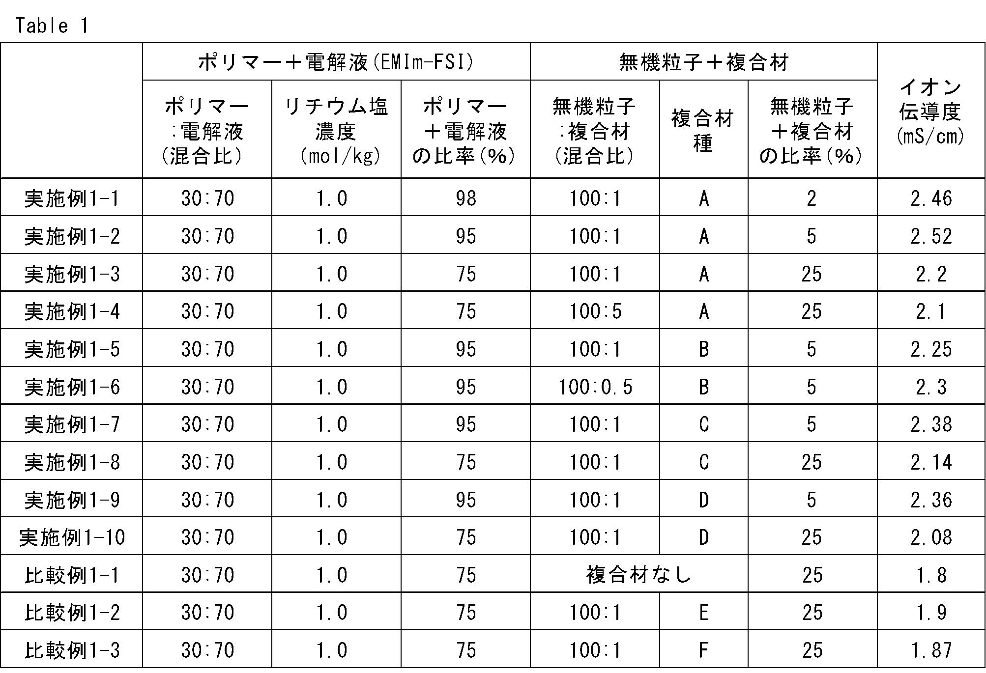
- the prepared electrolyte solution was applied onto a SUS foil having a thickness of 20 ⁇ m using an applicator, and then vacuum dried at 25 ° C. for 2 hours. Then, the polyether acrylate was polymerized by vacuum heating at 80 ° C. for 12 hours to obtain an electrolyte coating film having the composition ratio shown in Table 1 below.
- the betaine of this embodiment and the substitute of betaine of this embodiment are collectively referred to as "composite material".
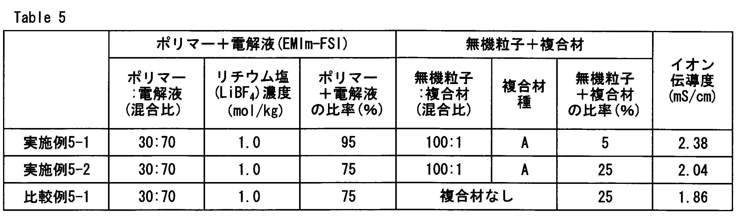
- the lithium salt concentration (mol / kg) means the content (mol) of the lithium salt with respect to the sum (kg) of the contents of the ionic liquid and the polymer.
- the "polymer + electrolyte ratio” in the table means the sum (%) of the polymer and the electrolyte with respect to the total amount of the electrolyte.
- the “ratio of inorganic particles + composite material” in the table means the sum (%) of the inorganic particles and the composite material with respect to the total amount of the electrolyte.
- the obtained electrolyte membrane according to Example 1-1 was punched to a diameter of 16 ⁇ , and then AC impedance was measured to calculate the ionic conductivity by the method described later.
- Example 1-2 to Example 1-4 In the electrolyte membrane of Example 1-1, the electrolyte was prepared in the same manner as in Example 1-1 except that the ratio of the mass of the electrolyte solution other than the diluting solvent / the mass of the inorganic composite particles was changed to the ratio shown in Table 1 below. A film was prepared.
- Examples 1-5 to 1-6 In the electrolyte membrane of Example 1-1, inorganic composite particles prepared by using [2- (Methacrylolyloxy) ethyl] dimethyl (3-sulfoplyl) ammonia hydroxide, inner salt (Compound B) instead of Compound A were used.
- An electrolyte membrane was prepared by the same method as in Example 1-1 except that the ratio of the mass of the electrolyte solution other than the diluting solvent / the mass of the inorganic composite particles was changed to the ratio shown in Table 1.
- the chemical formula (2) of compound B is shown below.
- Example 1-7 to 1-8> In the electrolyte membrane of Example 1-1, 1-Propanaminium, N, N-dimethyl-N- (3-phosphonopropyl) -3- (trimethoxysil)-, inner solvent (Compound C) was used instead of Compound A.
- An electrolyte membrane was prepared by the same method as in Example 1-1, except that the ratio of the mass of the electrolyte solution other than the diluting solvent / the mass of the inorganic composite particles was changed to the ratio shown in Table 1. ..
- the chemical formula (3) of compound C is shown below.
- Examples 1-9 to 1-10> In the electrolyte membrane of Example 1-1, 1-Propanaminium, 3-carboxy-N, N-dimethyl-N- [3- (trimethoxysilyl) probel]-, inner salt (Compound D) was used instead of Compound A.
- the electrolyte membrane was prepared by the same method as in Example 1-1, except that the prepared inorganic composite particles were used and the ratio of the mass of the electrolyte solution other than the diluting solvent / the mass of the inorganic composite particles was changed to the ratio shown in Table 1. Made.
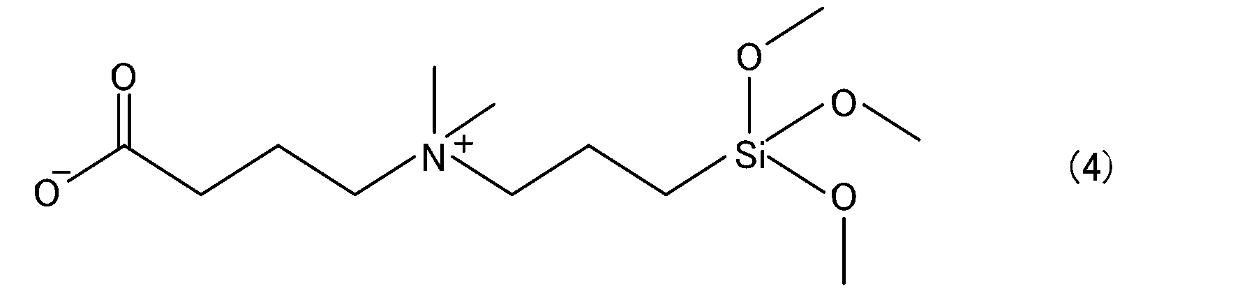
- the chemical formula (4) of compound D is shown below.
- Example 1-1 ⁇ Comparative Example 1-1>
- alumina was used instead of the inorganic composite particles prepared using compound A, and the mass / alumina mass ratio of the electrolyte solution other than the diluting solvent was changed to the ratio shown in Table 1.
- An electrolyte membrane was prepared by the same method as in Example 1-1 except for the above points.
- Example 1-1 In the electrolyte membrane of Example 1-1, inorganic composite particles prepared using 1-Alkylaminium, N- (carboxymethyl) -N, N-dimethyl-, inner salt (Compound E) were used instead of Compound A.
- An electrolyte membrane was prepared by the same method as in Example 1-1, except that the ratio of the mass of the electrolyte solution other than the diluting solvent / the mass of the inorganic composite particles was changed to the ratio shown in Table 1.
- the chemical formula (5) of compound E is shown below. While the compound E has a betaine structure, it does not have a functional group other than the betaine structure.
- R means an alkyl group having 12 to 16 carbon atoms
- Example 1-1 In the electrolyte membrane of Example 1-1, inorganic composite particles prepared using Trimethyl [3- (trimethoxysilyl) polypeptide] ammonium Chloride (Compound F) were used instead of Compound A, except for the diluting solvent of the electrolyte solution.
- An electrolyte membrane was prepared by the same method as in Example 1-1, except that the ratio of mass / inorganic composite particle mass was changed to the ratio shown in Table 1.
- the chemical formula (6) of compound F is shown below. Compound F does not have a betaine structure.
- Comparative Example 1-1 since only the inorganic particles were used instead of the inorganic composite particles, the ionic conductivity was lower than that of the Examples.
- Comparative Example 1-2 used inorganic composite particles using a compound having no functional group while having a betaine structure, and therefore had lower ionic conductivity than Examples. Further, since Comparative Examples 1-3 used inorganic composite particles using a compound having no betaine structure, the ionic conductivity was lower than that of Examples.
- Example 2-1 to Example 2-4> In the electrolyte membrane of Example 1-1, except that (i) the ratio of the lithium salt concentration and (ii) the mass of the electrolyte solution other than the diluting solvent / the mass of the inorganic composite particles was changed to the ratio shown in Table 2 below. , An electrolyte membrane was prepared by the same method as in Example 1-1.
- Example 2-1 In the electrolyte membrane of Example 1-1, alumina was used instead of the inorganic composite particles using compound A, (ii) the lithium salt concentration, and (iii) the mass of the electrolyte solution other than the diluting solvent.
- An electrolyte membrane was prepared by the same method as in Example 1-1 except that the ratio of / alumina mass was changed to the ratio shown in Table 2.
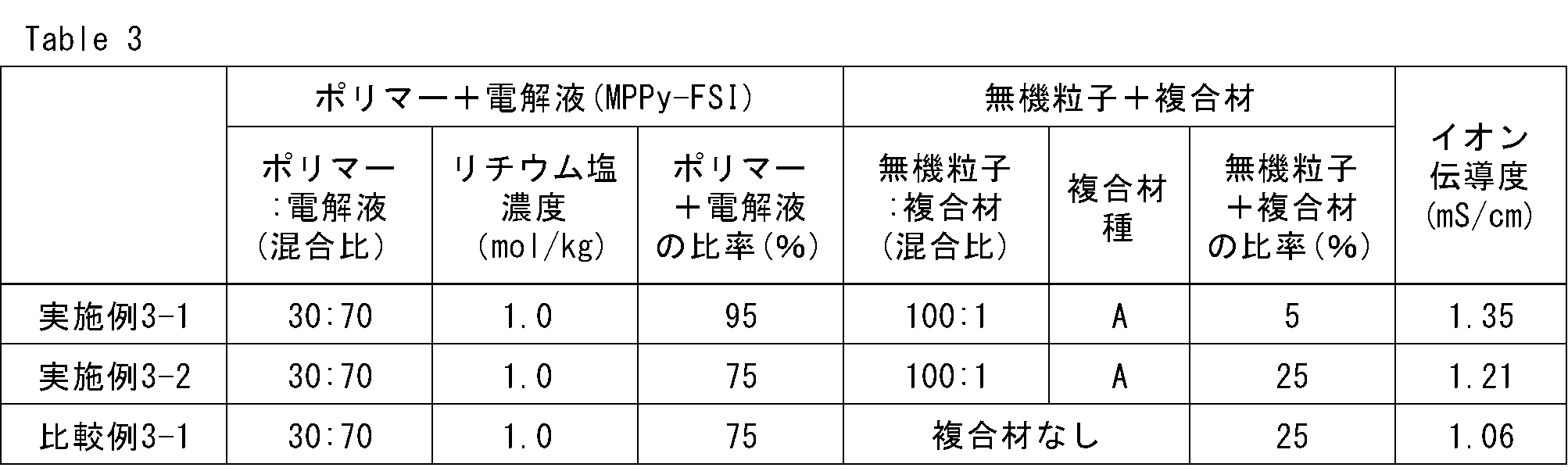
- Example 3-1 to Example 3-2> In the electrolyte membrane of Example 1-1, instead of EMIm-FSI as the electrolytic solution, 1-methyl-1-propyl-pyrrolidinium bis (fluorosulfonyl) inorganic (MPPy-FSI) (manufactured by Daiichi Kogyo Seiyaku Co., Ltd., product name: By the same method as in Example 1-1, except that Elexel IL-120) was used and the ratio of the mass of the electrolyte solution other than the diluting solvent / the mass of the inorganic composite particles was changed to the ratio shown in Table 3 below. An electrolyte membrane was prepared.
- MPPy-FSI 1-methyl-1-propyl-pyrrolidinium bis (fluorosulfonyl) inorganic
- Example 3-1 In the electrolyte membrane of Example 1-1, alumina was used instead of the inorganic composite particles, MPPy-FSI was used as the electrolytic solution instead of EMIm-FSI, and the mass of the electrolyte solution other than the diluting solvent / alumina mass.
- An electrolyte membrane was prepared by the same method as in Example 1-1 except that the ratio was changed to the ratio shown in Table 3.
- Example 3-1 Example 3-1
- Example 3-2 Comparative Example 3-1 even when an electrolytic solution different from that of Experiment 1 was used, the compound having a betaine structure and a functional group and the compound. It was found that the examples containing the inorganic composite particles in which the inorganic particles were compounded had higher ionic conductivity than the comparative examples in which the inorganic particles were not.
- Example 5-1 to Example 5-2> In the electrolyte membrane of Example 1-1, Lithium tetrafluoroborate (LiBF 4 ) was used instead of LiFSI as the lithium salt, and the ratio of the mass of the electrolyte solution other than the diluting solvent / the mass of the inorganic composite particles is shown in Table 5 below.
- An electrolyte membrane was prepared by the same method as in Example 1-1 except that it was changed to.
- Example 5-1 In the electrolyte membrane of Example 1-1, alumina was used instead of the inorganic composite particles, LiBF 4 was used instead of LiFSI as the lithium salt, and the mass / alumina mass ratio of the electrolyte solution other than the diluting solvent was determined.
- An electrolyte membrane was prepared by the same method as in Example 1-1 except that the ratio was changed to that shown in Table 5.
- the electrolyte membrane was prepared by the same method as in Example 1-1, except that 6) was used and the ratio of the mass of the electrolyte solution other than the diluting solvent / the mass of the inorganic composite particles was changed to the ratio shown in Table 6 below. Made.
- An electrolyte membrane was prepared by the same method as in Example 1-1, except that LiPF 6 was used and the ratio of mass / alumina mass of the electrolyte solution other than the diluting solvent was changed to the ratio shown in Table 6.
- Example 7-1 Preparation of inorganic composite particles
- Inorganic composite particles were obtained by the same method as in Example 1-1.
- the prepared composite electrolyte solution was applied onto a SUS foil having a thickness of 20 ⁇ m using an applicator, and then dried at 80 ° C. for 6 hours. Then, by vacuum heating at 80 ° C. for 10 hours, a composite electrolyte coating film having a composition ratio shown in Table 7 below was obtained.
- the ionic conductivity of the obtained composite electrolyte membrane according to Example 7-1 was calculated by punching the composite electrolyte membrane to a diameter of 16 ⁇ and then performing AC impedance measurement.
- the composite electrolyte membrane of Example 7-1 was prepared by the same method as in Example 7-1 except that the ratio of the electrolyte solution mass / the inorganic composite particle mass was changed to the ratio shown in Table 7. ..
- Example 7-1 ⁇ Comparative Example 7-1 to Comparative Example 7-2>
- alumina was used instead of the inorganic composite particles, and the ratio of the electrolyte solution mass / alumina mass was changed to the ratio shown in Table 7, except that the ratio was changed to that of Example 7-1.
- a composite electrolyte membrane was prepared by the same method.
- the ionic conductivity of the obtained electrolyte pellet was calculated by measuring the thickness and then measuring the AC impedance.
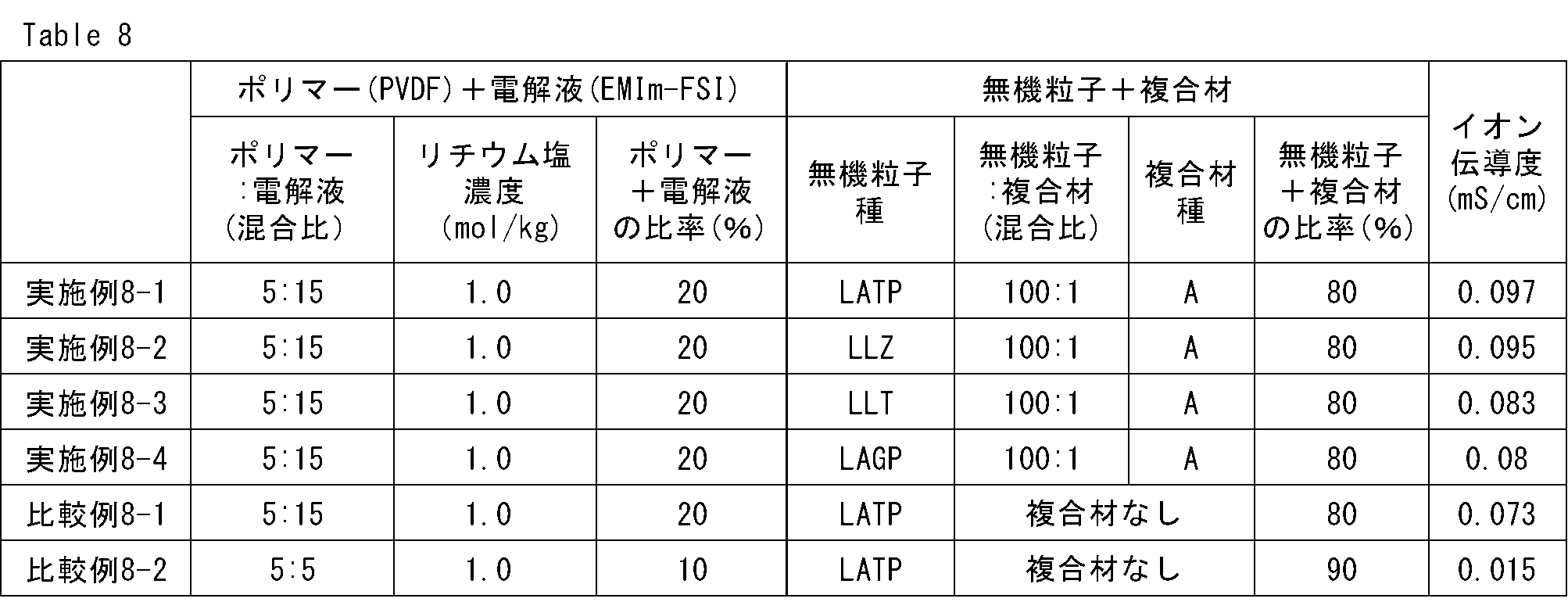
- an electrolyte pellet of Example 8-1 was prepared by the same method as in Example 8-1 except that Li 7 La 3 Zr 2 O 12 (LLZ) was used instead of LATP as the inorganic particles. ..
- Example 8-3> In the electrolyte pellet of Example 8-1, the electrolyte pellet was prepared by the same method as in Example 8-1 except that La-Li-Ti-based perovskite oxide (LLT) was used instead of LATP as the inorganic particles. Made.
- LLT La-Li-Ti-based perovskite oxide
- Example 8-4> In the electrolyte pellet of Example 8-1, Li 1.5 Al 0.5 Ge 1.5 (PO 4 ) 3 (LAGP) was used instead of LATP as the inorganic particles, except that Li 1.5 Al 0.5 Ge 1.5 (LAGP) was used as the inorganic particles. Electrolyte pellets were prepared by the same method.
- the present invention is not limited to the above-described embodiment, and can be realized with various configurations within a range not deviating from the gist thereof.
- the embodiment corresponding to the technical feature in each embodiment described in the column of the outline of the invention the technical feature in the embodiment may be used to solve a part or all of the above-mentioned problems, or the above-mentioned above. It is possible to replace or combine them as appropriate to achieve some or all of the effects. Further, if the technical feature is not described as essential in the present specification, it can be deleted as appropriate.
- the electrolyte of this embodiment has high ionic conductivity. Therefore, the power storage device provided with the electrolyte of the present embodiment can be suitably used as a power source for mobile devices, and for example, wearable devices, electric tools, electric bicycles, electric wheelchairs, robots, electric vehicles, emergency power sources and large power supplies. It is also useful for fixed-capacity power supplies.
Landscapes
- Chemical & Material Sciences (AREA)
- Engineering & Computer Science (AREA)
- Chemical Kinetics & Catalysis (AREA)
- Electrochemistry (AREA)
- Power Engineering (AREA)
- General Chemical & Material Sciences (AREA)
- Manufacturing & Machinery (AREA)
- Materials Engineering (AREA)
- Microelectronics & Electronic Packaging (AREA)
- Inorganic Chemistry (AREA)
- Physics & Mathematics (AREA)
- Spectroscopy & Molecular Physics (AREA)
- Secondary Cells (AREA)
- Conductive Materials (AREA)
Abstract
Description
A1.電解質
本発明の一実施形態である電解質は、(メタ)アクリロキシ基、Si(OR)3基(Rは、水素原子または炭素数1~3のアルキル基)、Al(OR)2基(Rは、水素原子または炭素数1~3のアルキル基)から選択された1種または2種以上の官能基及びベタイン構造を有する化合物と、無機粒子と、が複合している無機複合粒子を含むことを特徴とする。本明細書において、「複合」とは、例えば、イオン結合、共有結合、水素結合、ファンデルワールス力等により、相互に結びつけられた状態を示す。本実施形態の電解質によれば、メカニズムは定かではないが、イオン伝導度を向上させることができる。
Y-A-N+R1R2-B-Z-
Yは(メタ)アクリロキシ基、Si(OR)3基(Rは、水素原子または炭素数1~3のアルキル基)、又はAl(OR)2基(Rは、水素原子または炭素数1~3のアルキル基)を示す。Z-はSO3 -、PO3H-、又はCOO-を示す。AとBは各々独立に炭素数1~6のアルキレン基を示す。AとBは各々独立に炭素数2~4のアルキレン基であることが好ましい。R1とR2は各々独立に炭素数1~6のアルキル基を示す。R1とR2は各々独立に炭素数2~4のアルキル基であることが好ましい。
(MI,MII1/2)m(AlmSinO2(m+n))・xH2O
式中において、nおよびmはn≧m>0を満たし、xはx≧0を満たしている。また、式中のMIは、Li+、Na+、K+等の一価の金属イオンを示し、MIIは、Ca2+、Mg2+、Ba2+等の二価の金属イオンを示している。
他の実施形態として、上述の電解質を備える蓄電デバイスが提供される。本実施形態の蓄電デバイスは、さらに、正極と、負極とを備える。蓄電デバイスとしては、特に限定されず、例えば、リチウムイオン二次電池、電気二重層キャパシタ、リチウムイオンキャパシタ等が挙げられる。以下では、蓄電デバイスの一例として、リチウムイオン二次電池を用いて説明する。
以下、実施例により本発明をさらに具体的に説明するが、本発明は以下の実施例に限定されない。なお、例中、特に限定のない限り、「%」は「質量%」を意味し、「比」は「質量比」を意味する。
<実施例1-1>
(電解質溶液の調製)
以下の作業は露点-50℃以下の乾燥空気雰囲気下で実施した。ポリマー電解質でありかつマトリクス材である四官能ポリエーテルアクリレート(第一工業製薬社製、製品名:エレクセルTA-210)を20.1質量部、イオン液体系の電解液溶媒である1-ethyl-3-methyl-imidazolium bis(fluorosulfonyl)imide(EMIm-FSI)(第一工業製薬社製、製品名:エレクセルIL-110)を46.9質量部、リチウム塩であるLithium bis(fluorosulfonyl)imide(LiFSI)を12.5質量部、アゾ系の開始剤である2,2’-Azobis(2,4-dimethylvaleronitrile)(和光純薬社製、製品名:V-65)を0.5質量部、および希釈溶剤である1,2-Dimethoxyethane(DME)を20質量部配合して混合することにより、電解質溶液を作製した。
N,N-dimethyl-(trihydroxysilyl)propyl-N-sulfopropyl-ammonium,inner salt(化合物A)を0.33質量%溶解させた水溶液に対し、アルミナ(粒径0.5μm、BET比表面積5.9m2/g)を化合物A/アルミナ=1/100となるように混合した。その後、室温(25℃)で12時間攪拌することによりアルミナと化合物Aを複合化させた後、水溶液とアルミナを濾別することにより、無機複合粒子を得た。ここで、以下に、化合物Aの化学式(1)を示す。

電解質溶液の希釈溶剤以外の質量/無機複合粒子の質量=98/2となるように電解質溶液と無機複合粒子を混合した後、自公転攪拌装置を用いて無機複合粒子を溶液中に分散させることにより、電解質溶液を作製した。
実施例1-1の電解質膜において、電解質溶液の希釈溶剤以外の質量/無機複合粒子質量の比率を以下の表1に示す比率に変更した以外は、実施例1-1と同様の方法により電解質膜を作製した。
実施例1-1の電解質膜において、化合物Aの代わりに[2-(Methacryloyloxy)ethyl]dimethyl(3-sulfopropyl)ammonium hydroxide,inner salt(化合物B)を用いて作製した無機複合粒子を使用し、電解質溶液の希釈溶剤以外の質量/無機複合粒子質量の比率を表1に示す比率に変更した以外は、実施例1-1と同様の方法により電解質膜を作製した。ここで、以下に、化合物Bの化学式(2)を示す。

実施例1-1の電解質膜において、化合物Aの代わりに1-Propanaminium,N,N-dimethyl-N-(3-phosphonopropyl)-3-(trimethoxysilyl)-,inner salt(化合物C)を用いて作製した無機複合粒子を使用し、電解質溶液の希釈溶剤以外の質量/無機複合粒子質量の比率を表1に示す比率に変更した以外は、実施例1-1と同様の方法により電解質膜を作製した。ここで、以下に、化合物Cの化学式(3)を示す。

実施例1-1の電解質膜において、化合物Aの代わりに1-Propanaminium,3-carboxy-N,N-dimethyl-N-[3-(trimethoxysilyl)propyl]-,inner salt(化合物D)を用いて作製した無機複合粒子を使用した点、電解質溶液の希釈溶剤以外の質量/無機複合粒子質量の比率を表1示す比率に変更した点以外は、実施例1-1と同様の方法により電解質膜を作製した。ここで、以下に、化合物Dの化学式(4)を示す。
実施例1-1の電解質膜において、化合物Aを用いて作製した無機複合粒子の代わりにアルミナを使用した点、電解質溶液の希釈溶剤以外の質量/アルミナ質量の比率を表1に示す比率に変更した点以外は、実施例1-1と同様の方法により電解質膜を作製した。
実施例1-1の電解質膜において、化合物Aの代わりに、1-Alkylaminium, N-(carboxymethyl)-N,N-dimethyl-, inner salt(化合物E)を用いて作製した無機複合粒子を使用した点、電解質溶液の希釈溶剤以外の質量/無機複合粒子質量の比率を表1に示す比率に変更した点以外は、実施例1-1と同様の方法により電解質膜を作製した。ここで、以下に、化合物Eの化学式(5)を示す。なお、化合物Eは、ベタイン構造を備える一方で、ベタイン構造以外の官能基を有さない。

実施例1-1の電解質膜において、化合物Aの代わりに、Trimethyl[3-(trimethoxysilyl)propyl]ammonium Chloride(化合物F)を用いて作製した無機複合粒子を使用した点、電解質溶液の希釈溶剤以外の質量/無機複合粒子質量の比率を表1に示す比率に変更した点以外は、実施例1-1と同様の方法により電解質膜を作製した。ここで、以下に、化合物Fの化学式(6)を示す。なお、化合物Fは、ベタイン構造を備えない。

各実施例または各比較例で得られた電解質膜について、その厚さ(膜厚)および断面積を測定した。得られた電解質を2極セル内に入れた後、バイオロジック社(Bio-Logic SAS)製インピーダンスアナライザー(製品名:SP-150)を用いて、25℃、周波数1MHz~0.1Hzの条件で電気化学インピーダンス(EIS)を測定することにより、電解質のバルク抵抗値を得た。そして、得られた抵抗値と下記式とを用いて、電解質膜のイオン伝導度(σ)を得た。
σ = l/(s・R)
(式中、lは電解質膜の厚さ(cm)を表し、sは断面積(cm2)を表し、Rはバルク抵抗値(Ω)を表す。)
<実施例2-1~実施例2-4>
実施例1-1の電解質膜において、(i)リチウム塩濃度と、(ii)電解質溶液の希釈溶剤以外の質量/無機複合粒子質量の比率を以下の表2に示す比率に変更したこと以外は、実施例1-1と同様の方法により電解質膜を作製した。
実施例1-1の電解質膜において、(i)化合物Aを用いた無機複合粒子ではなく、アルミナを使用した点と、(ii)リチウム塩濃度と、(iii)電解質溶液の希釈溶剤以外の質量/アルミナ質量の比率を表2に示す比率に変更したこと以外は、実施例1-1と同様の方法により電解質膜を作製した。

<実施例3-1~実施例3-2>
実施例1-1の電解質膜において、電解液としてEMIm-FSIの代わりに、1-methyl-1-propyl-pyrrolidinium bis(fluorosulfonyl)imide(MPPy-FSI)(第一工業製薬社製、製品名:エレクセルIL-120)を使用した点、電解質溶液の希釈溶剤以外の質量/無機複合粒子質量の比率を以下の表3に示す比率に変更した点以外は、実施例1-1と同様の方法により電解質膜を作製した。
実施例1-1の電解質膜において、無機複合粒子の代わりにアルミナを使用した点、電解液としてEMIm-FSIではなくMPPy-FSIを使用した点、電解質溶液の希釈溶剤以外の質量/アルミナ質量の比率を表3に示す比率に変更した点以外は、実施例1-1と同様の方法により電解質膜を作製した。
<実施例4-1~実施例4-2>
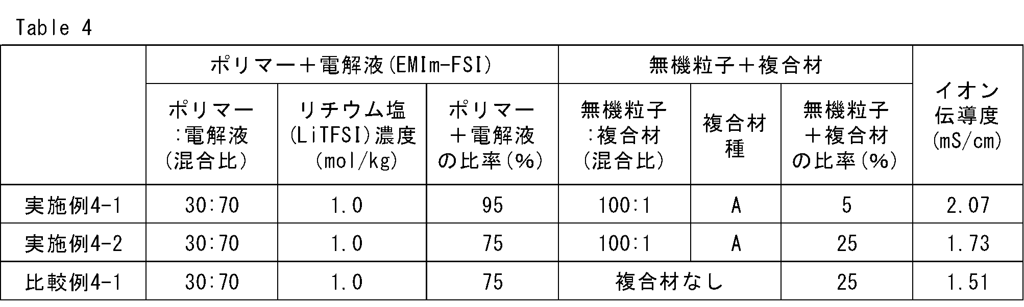
実施例1-1の電解質膜において、リチウム塩としてLiFSIの代わりにLithium bis(trifluoromethanesulfonyl)imide(LiTFSI)を使用した点、電解質溶液の希釈溶剤以外の質量/無機複合粒子質量の比率を以下の表4に示す比率に変更した点以外は、実施例1-1と同様の方法により電解質膜を作製した。
実施例1-1の電解質膜において、無機複合粒子の代わりにアルミナを使用した点、リチウム塩としてLiFSIの代わりにLiTFSIを使用した点、電解質溶液の希釈溶剤以外の質量/アルミナ質量の比率を表4に示す比率に変更した点以外は、実施例1-1と同様の方法により電解質膜を作製した。
<実施例5-1~実施例5-2>
実施例1-1の電解質膜において、リチウム塩としてLiFSIの代わりにLithiumtetrafluoroborate(LiBF4)を使用した点、電解質溶液の希釈溶剤以外の質量/無機複合粒子質量の比率を以下の表5に示す比率に変更した点以外は、実施例1-1と同様の方法により電解質膜を作製した。
実施例1-1の電解質膜において、無機複合粒子の代わりにアルミナを使用した点、リチウム塩としてLiFSIの代わりにLiBF4を使用した点、電解質溶液の希釈溶剤以外の質量/アルミナ質量の比率を表5に示す比率に変更した点以外は、実施例1-1と同様の方法により電解質膜を作製した。
<実施例6-1~実施例6-2>
実施例1-1の電解質膜において、電解液としてEMIm-FSIの代わりにEthylene Carbonate(EC)/Propylene Carbonate(PC)=1/1を使用した点、リチウム塩としてLiFSIの代わりにLithium Hexafluorophosphate(LiPF6)を使用した点、電解質溶液の希釈溶剤以外の質量/無機複合粒子質量の比率を以下の表6に示す比率に変更した点以外は、実施例1-1と同様の方法により電解質膜を作製した。
実施例1-1の電解質膜において、無機複合粒子の代わりにアルミナを使用した点、電解液としてEMIm-FSIの代わりにEC/PC=1/1を使用した点、リチウム塩としてLiFSIの代わりにLiPF6を使用した点、電解質溶液の希釈溶剤以外の質量/アルミナ質量の比率を表6に示す比率に変更した点以外は、実施例1-1と同様の方法により電解質膜を作製した。

<実施例7-1>
(無機複合粒子の調製)
実施例1-1と同じ方法により無機複合粒子を得た。
マトリクス材であるカーボネート骨格を持つ分子量6万程度の10質量%ポリウレタン/N-methylpyrrolidone(NMP)溶液34.5質量部と、電解液溶媒であるEMImFSI(第一工業製薬株式会社製、製品名:エレクセルIL-110)20.3質量部と、リチウム塩であるLiFSI3.8質量部とを混合した後、自公転攪拌装置を用いて無機複合粒子41.4質量部を溶液中に分散させることにより、複合電解質溶液を作製した。
実施例7-1の複合電解質膜において、電解質溶液質量/無機複合粒子質量の比率を表7に示す比率に変更した点以外は、実施例7-1と同様の方法により複合電解質膜を作製した。
実施例7-1の複合電解質膜において、無機複合粒子の代わりにアルミナを使用した点、電解質溶液質量/アルミナ質量の比率を表7に示す比率に変更した点以外は、実施例7-1と同様の方法により複合電解質膜を作製した。

<実施例8-1>
(無機複合粒子の調製)
上述の化合物Aを0.33質量%溶解させた水溶液に対し、無機粒子としてのLi1+x+yTi2-xAlxP3-ySiyO12(0<x<2,0<y<3))(LATP)を化合物A/LATP=1/100となるように混合した。その後、室温(25℃)で12時間攪拌することにより無機粒子と化合物Aを複合させた後、水溶液と無機粒子を濾別することにより、無機複合粒子を得た。
マトリクス材であるPoly Vinylidene DiFluoride(PVDF)(分子量約30万)を2.5質量部と、電解液溶媒であるEMImFSI(第一工業製薬株式会社製、製品名:エレクセルIL-110)6.3質量部と、リチウム塩であるLiFSI1.2質量部と、希釈溶剤であるDME50質量部とを混合した後、自公転攪拌装置を用いて無機複合粒子を溶液中に分散させることにより、電解質溶液を作製した。その後、希釈溶剤を減圧乾燥することにより、電解質粉末を得た。
作製した電解質粉末を、直径12φの円筒型の金型に0.3g程度入れた後、200kgf/cm2の圧力で30秒間一軸加圧することにより、以下の表8に示す組成比の電解質ペレットを作製した。
実施例8-1の電解質ペレットにおいて、無機粒子としてLATPの代わりにLi7La3Zr2O12(LLZ)を使用した点以外は、実施例8-1と同様の方法により電解質ペレットを作製した。
実施例8-1の電解質ペレットにおいて、無機粒子としてLATPの代わりにLa-Li-Ti系ペロブスカイト型酸化物(LLT)を使用した点以外は、実施例8-1と同様の方法により電解質ペレットを作製した。
実施例8-1の電解質ペレットにおいて、無機粒子としてLATPの代わりにLi1.5Al0.5Ge1.5(PO4)3(LAGP)を使用した点以外は、実施例8-1と同様の方法により電解質ペレットを作製した。
実施例8-1の電解質ペレットにおいて、無機複合粒子の代わりにLATPを使用した点、電解質溶液の希釈溶剤以外の質量/LATP質量の比率を表8に示す比率に変更した点以外は、実施例8-1と同様の方法により電解質ペレットを作製した。
Claims (7)
- (メタ)アクリロキシ基、Si(OR)3基(Rは、水素原子または炭素数1~3のアルキル基)、Al(OR)2基(Rは、水素原子または炭素数1~3のアルキル基)から選択された1種または2種以上の官能基及びベタイン構造を有する化合物と、無機粒子と、が複合している無機複合粒子を含むことを特徴とする、電解質。
- 請求項1に記載の電解質であって、
前記官能基が、(メタ)アクリロキシ基、Si(OR)3基(Rは、水素原子または炭素数1~3のアルキル基)から選択された1種または2種以上であることを特徴とする、電解質。 - 請求項1または請求項2に記載の電解質であって、
前記ベタイン構造が、SO3 -、PO3H-、及びCOO-から選択された1種または2種以上と、4級アンモニウムカチオンと、を有することを特徴とする、電解質。 - 請求項1から請求項3までのいずれか1項に記載の電解質であって、
前記化合物の含有量が、前記無機粒子の含有量100質量部に対し、0.1質量部以上10質量部以下であることを特徴とする、電解質。 - 請求項1から請求項4までのいずれか1項に記載の電解質であって、
前記無機粒子のBET比表面積が1.0m2/g以上であることを特徴とする、電解質。 - 請求項1から請求項5までのいずれか1項に記載の電解質であって、
無機複合粒子の含有量が、電解質100質量部に対し、1質量部以上50質量部以下であることを特徴とする、電解質。 - 請求項1から請求項6までのいずれか1項に記載の電解質を備える蓄電デバイス。
Priority Applications (5)
| Application Number | Priority Date | Filing Date | Title |
|---|---|---|---|
| KR1020227030624A KR20220158697A (ko) | 2020-03-27 | 2021-03-15 | 전해질 및 축전 디바이스 |
| JP2022509955A JP7689946B2 (ja) | 2020-03-27 | 2021-03-15 | 電解質及び蓄電デバイス |
| CN202180020765.XA CN115298871A (zh) | 2020-03-27 | 2021-03-15 | 电解质及蓄电设备 |
| EP21776647.6A EP4131303A4 (en) | 2020-03-27 | 2021-03-15 | ELECTROLYTE AND POWER STORAGE DEVICE |
| US17/913,517 US20230106336A1 (en) | 2020-03-27 | 2021-03-15 | Electrolyte and power storage device |
Applications Claiming Priority (4)
| Application Number | Priority Date | Filing Date | Title |
|---|---|---|---|
| JP2020-058183 | 2020-03-27 | ||
| JP2020058183 | 2020-03-27 | ||
| JP2020170080 | 2020-10-07 | ||
| JP2020-170080 | 2020-10-07 |
Publications (1)
| Publication Number | Publication Date |
|---|---|
| WO2021193203A1 true WO2021193203A1 (ja) | 2021-09-30 |
Family
ID=77890292
Family Applications (1)
| Application Number | Title | Priority Date | Filing Date |
|---|---|---|---|
| PCT/JP2021/010431 Ceased WO2021193203A1 (ja) | 2020-03-27 | 2021-03-15 | 電解質及び蓄電デバイス |
Country Status (7)
| Country | Link |
|---|---|
| US (1) | US20230106336A1 (ja) |
| EP (1) | EP4131303A4 (ja) |
| JP (1) | JP7689946B2 (ja) |
| KR (1) | KR20220158697A (ja) |
| CN (1) | CN115298871A (ja) |
| TW (1) | TWI864239B (ja) |
| WO (1) | WO2021193203A1 (ja) |
Cited By (1)
| Publication number | Priority date | Publication date | Assignee | Title |
|---|---|---|---|---|
| CN112615049A (zh) * | 2020-12-21 | 2021-04-06 | 凯博能源科技有限公司 | 固态电解质及包含它的电池 |
Families Citing this family (2)
| Publication number | Priority date | Publication date | Assignee | Title |
|---|---|---|---|---|
| JP6916337B1 (ja) * | 2020-03-27 | 2021-08-11 | 第一工業製薬株式会社 | リチウムイオン二次電池 |
| KR20240004428A (ko) * | 2021-03-31 | 2024-01-11 | 이오에스 에너지 테크놀로지 홀딩스, 엘엘씨 | 정적 할로겐화 아연 배터리의 캐소드 표면에 결합된 할로겐 착화제 |
Citations (2)
| Publication number | Priority date | Publication date | Assignee | Title |
|---|---|---|---|---|
| JPH0262184B2 (ja) | 1985-10-04 | 1990-12-25 | Chino Corp | |
| JP2016530676A (ja) * | 2013-11-01 | 2016-09-29 | エルジー・ケム・リミテッド | 燃料電池およびその製造方法 |
Family Cites Families (15)
| Publication number | Priority date | Publication date | Assignee | Title |
|---|---|---|---|---|
| JP2000103899A (ja) * | 1998-09-29 | 2000-04-11 | Nippon Shokubai Co Ltd | 無機電解質塩含有高分子吸収体およびその製造方法 |
| DE102005051587A1 (de) * | 2005-10-27 | 2007-05-03 | Consortium für elektrochemische Industrie GmbH | Zwitterionische Strukturelemente aufweisende Partikel |
| US10087082B2 (en) * | 2006-06-06 | 2018-10-02 | Florida State University Research Foundation, Inc. | Stabilized silica colloid |
| US9399075B2 (en) * | 2008-12-29 | 2016-07-26 | General Electric Company | Nanoparticle contrast agents for diagnostic imaging |
| US8728440B2 (en) * | 2012-08-23 | 2014-05-20 | General Electric Company | Nanoparticulate compositions for diagnostic imaging |
| BRPI0923859B8 (pt) | 2008-12-29 | 2022-10-25 | Gen Electric | composição de agente de diagnóstico, e, método para a produção das nanopartículas |
| US8821838B2 (en) * | 2012-08-23 | 2014-09-02 | General Electric Company | Nanoparticulate compositions for diagnostic imaging |
| WO2014029814A1 (en) | 2012-08-23 | 2014-02-27 | General Electric Company | Nanoparticulate compositions for diagnostic imaging |
| CN103316599B (zh) * | 2013-06-26 | 2015-09-16 | 浙江大学 | 一种甜菜碱胶体纳米粒子改性壳聚糖纳滤膜的制备方法 |
| CN106232696B (zh) * | 2014-04-24 | 2020-06-05 | 3M创新有限公司 | 具有亲水表面的流体控制膜、其制造方法以及用于清洁结构化表面的方法 |
| EP3042722B1 (en) | 2015-01-07 | 2019-11-27 | Personal Genomics Inc. | Oriented loading systems and method for orienting a particle loaded in a well |
| CN106390146A (zh) | 2015-08-03 | 2017-02-15 | 天津大学 | 聚磺酸甜菜碱两性电解质修饰的磁性纳米粒子及其制备方法和应用 |
| WO2017061424A1 (ja) * | 2015-10-05 | 2017-04-13 | リンテック株式会社 | 正極、二次電池、及び二次電池の使用方法 |
| EP4102610B1 (en) | 2017-06-01 | 2026-03-04 | LG Energy Solution, Ltd. | Electrolyte composition, secondary cell, and method for manufacturing electrolyte sheet |
| KR101979897B1 (ko) * | 2018-10-29 | 2019-05-17 | 한밭대학교 산학협력단 | 쯔비터이온성 리튬-실리카 설포베타인 실란 및 이의 제조방법과 이를 포함하는 전해질 조성물. |
-
2021
- 2021-02-25 TW TW110106601A patent/TWI864239B/zh active
- 2021-03-15 JP JP2022509955A patent/JP7689946B2/ja active Active
- 2021-03-15 CN CN202180020765.XA patent/CN115298871A/zh active Pending
- 2021-03-15 US US17/913,517 patent/US20230106336A1/en active Pending
- 2021-03-15 KR KR1020227030624A patent/KR20220158697A/ko not_active Withdrawn
- 2021-03-15 WO PCT/JP2021/010431 patent/WO2021193203A1/ja not_active Ceased
- 2021-03-15 EP EP21776647.6A patent/EP4131303A4/en active Pending
Patent Citations (2)
| Publication number | Priority date | Publication date | Assignee | Title |
|---|---|---|---|---|
| JPH0262184B2 (ja) | 1985-10-04 | 1990-12-25 | Chino Corp | |
| JP2016530676A (ja) * | 2013-11-01 | 2016-09-29 | エルジー・ケム・リミテッド | 燃料電池およびその製造方法 |
Non-Patent Citations (1)
| Title |
|---|
| See also references of EP4131303A4 |
Cited By (1)
| Publication number | Priority date | Publication date | Assignee | Title |
|---|---|---|---|---|
| CN112615049A (zh) * | 2020-12-21 | 2021-04-06 | 凯博能源科技有限公司 | 固态电解质及包含它的电池 |
Also Published As
| Publication number | Publication date |
|---|---|
| US20230106336A1 (en) | 2023-04-06 |
| EP4131303A1 (en) | 2023-02-08 |
| EP4131303A4 (en) | 2024-05-08 |
| JPWO2021193203A1 (ja) | 2021-09-30 |
| TWI864239B (zh) | 2024-12-01 |
| KR20220158697A (ko) | 2022-12-01 |
| TW202143541A (zh) | 2021-11-16 |
| CN115298871A (zh) | 2022-11-04 |
| JP7689946B2 (ja) | 2025-06-09 |
Similar Documents
| Publication | Publication Date | Title |
|---|---|---|
| CN111295719B (zh) | 固体电解质材料和电池 | |
| CN101379653B (zh) | 使用离子性液体的锂二次电池 | |
| WO2019135315A1 (ja) | 固体電解質材料、および、電池 | |
| WO2019135319A1 (ja) | 固体電解質材料、および、電池 | |
| JPWO2018168505A1 (ja) | 固体電解質組成物、固体電解質含有シートおよび全固体二次電池、並びに、固体電解質組成物、固体電解質含有シートおよび全固体二次電池の製造方法 | |
| CN101853959A (zh) | 电解质溶液用材料及其用途 | |
| CN111668484A (zh) | 负极活性物质材料和蓄电装置 | |
| JP7689946B2 (ja) | 電解質及び蓄電デバイス | |
| CN114512708A (zh) | 一种锂离子复合固态电解质的制备方法及应用 | |
| JP6206044B2 (ja) | 負極活物質、負極活物質を含む負極、及びそれを用いたリチウムイオン二次電池 | |
| Nguyen et al. | Enhanced Performance of Lithium Polymer Batteries Based on the Nickel-Rich LiNi0. 8Mn0. 1Co0. 1O2 Cathode Material and Dual Salts | |
| JP5191931B2 (ja) | イオン液体を用いたリチウム二次電池 | |
| JP4168241B2 (ja) | 非水電解質電池 | |
| JP5391832B2 (ja) | 二次電池及びその製造方法 | |
| JP4415556B2 (ja) | 非水電解質電池 | |
| JP2020087711A (ja) | 無機固体電解質二次電池 | |
| JP6916337B1 (ja) | リチウムイオン二次電池 | |
| JP3587982B2 (ja) | 高分子固体電解質およびこれを用いたリチウム二次電池と電気二重層キャパシタ | |
| JP5564930B2 (ja) | 非水系二次電池用正極及び非水系二次電池 | |
| JP4479159B2 (ja) | 非水電解質電池 | |
| CN113471522B (zh) | 一种复合固态电解质及其制备方法和应用 | |
| JP2004071244A (ja) | 非水電解質電池 | |
| JP5402216B2 (ja) | 非水電解質二次電池 | |
| Chandra | In-Situ Polymerization of Methacrylate Based Solid Polymer Electrolyte for Solid State Lithium-Ion Batteries | |
| WO2025057311A1 (ja) | リチウム2次電池用電解液及びリチウム2次電池 |
Legal Events
| Date | Code | Title | Description |
|---|---|---|---|
| 121 | Ep: the epo has been informed by wipo that ep was designated in this application |
Ref document number: 21776647 Country of ref document: EP Kind code of ref document: A1 |
|
| ENP | Entry into the national phase |
Ref document number: 2022509955 Country of ref document: JP Kind code of ref document: A |
|
| WWE | Wipo information: entry into national phase |
Ref document number: 2021776647 Country of ref document: EP |
|
| ENP | Entry into the national phase |
Ref document number: 2021776647 Country of ref document: EP Effective date: 20221027 |
|
| NENP | Non-entry into the national phase |
Ref country code: DE |