WO2021193647A1 - ウインドシールド - Google Patents
ウインドシールド Download PDFInfo
- Publication number
- WO2021193647A1 WO2021193647A1 PCT/JP2021/012023 JP2021012023W WO2021193647A1 WO 2021193647 A1 WO2021193647 A1 WO 2021193647A1 JP 2021012023 W JP2021012023 W JP 2021012023W WO 2021193647 A1 WO2021193647 A1 WO 2021193647A1
- Authority
- WO
- WIPO (PCT)
- Prior art keywords
- glass plate
- end portion
- windshield
- wedge angle
- wedge
- Prior art date
- Legal status (The legal status is an assumption and is not a legal conclusion. Google has not performed a legal analysis and makes no representation as to the accuracy of the status listed.)
- Ceased
Links
Images


Classifications
-
- B—PERFORMING OPERATIONS; TRANSPORTING
- B60—VEHICLES IN GENERAL
- B60J—WINDOWS, WINDSCREENS, NON-FIXED ROOFS, DOORS, OR SIMILAR DEVICES FOR VEHICLES; REMOVABLE EXTERNAL PROTECTIVE COVERINGS SPECIALLY ADAPTED FOR VEHICLES
- B60J1/00—Windows; Windscreens; Accessories therefor
- B60J1/02—Windows; Windscreens; Accessories therefor arranged at the vehicle front, e.g. structure of the glazing, mounting of the glazing
-
- B—PERFORMING OPERATIONS; TRANSPORTING
- B32—LAYERED PRODUCTS
- B32B—LAYERED PRODUCTS, i.e. PRODUCTS BUILT-UP OF STRATA OF FLAT OR NON-FLAT, e.g. CELLULAR OR HONEYCOMB, FORM
- B32B17/00—Layered products essentially comprising sheet glass, or glass, slag, or like fibres
- B32B17/06—Layered products essentially comprising sheet glass, or glass, slag, or like fibres comprising glass as the main or only constituent of a layer, next to another layer of a specific material
- B32B17/10—Layered products essentially comprising sheet glass, or glass, slag, or like fibres comprising glass as the main or only constituent of a layer, next to another layer of a specific material of synthetic resin
- B32B17/10005—Layered products essentially comprising sheet glass, or glass, slag, or like fibres comprising glass as the main or only constituent of a layer, next to another layer of a specific material of synthetic resin laminated safety glass or glazing
- B32B17/10009—Layered products essentially comprising sheet glass, or glass, slag, or like fibres comprising glass as the main or only constituent of a layer, next to another layer of a specific material of synthetic resin laminated safety glass or glazing characterized by the number, the constitution or treatment of glass sheets
- B32B17/10036—Layered products essentially comprising sheet glass, or glass, slag, or like fibres comprising glass as the main or only constituent of a layer, next to another layer of a specific material of synthetic resin laminated safety glass or glazing characterized by the number, the constitution or treatment of glass sheets comprising two outer glass sheets
-
- B—PERFORMING OPERATIONS; TRANSPORTING
- B32—LAYERED PRODUCTS
- B32B—LAYERED PRODUCTS, i.e. PRODUCTS BUILT-UP OF STRATA OF FLAT OR NON-FLAT, e.g. CELLULAR OR HONEYCOMB, FORM
- B32B17/00—Layered products essentially comprising sheet glass, or glass, slag, or like fibres
- B32B17/06—Layered products essentially comprising sheet glass, or glass, slag, or like fibres comprising glass as the main or only constituent of a layer, next to another layer of a specific material
- B32B17/10—Layered products essentially comprising sheet glass, or glass, slag, or like fibres comprising glass as the main or only constituent of a layer, next to another layer of a specific material of synthetic resin
- B32B17/10005—Layered products essentially comprising sheet glass, or glass, slag, or like fibres comprising glass as the main or only constituent of a layer, next to another layer of a specific material of synthetic resin laminated safety glass or glazing
- B32B17/1055—Layered products essentially comprising sheet glass, or glass, slag, or like fibres comprising glass as the main or only constituent of a layer, next to another layer of a specific material of synthetic resin laminated safety glass or glazing characterized by the resin layer, i.e. interlayer
- B32B17/10559—Shape of the cross-section
- B32B17/10568—Shape of the cross-section varying in thickness
-
- B—PERFORMING OPERATIONS; TRANSPORTING
- B32—LAYERED PRODUCTS
- B32B—LAYERED PRODUCTS, i.e. PRODUCTS BUILT-UP OF STRATA OF FLAT OR NON-FLAT, e.g. CELLULAR OR HONEYCOMB, FORM
- B32B17/00—Layered products essentially comprising sheet glass, or glass, slag, or like fibres
- B32B17/06—Layered products essentially comprising sheet glass, or glass, slag, or like fibres comprising glass as the main or only constituent of a layer, next to another layer of a specific material
- B32B17/10—Layered products essentially comprising sheet glass, or glass, slag, or like fibres comprising glass as the main or only constituent of a layer, next to another layer of a specific material of synthetic resin
- B32B17/10005—Layered products essentially comprising sheet glass, or glass, slag, or like fibres comprising glass as the main or only constituent of a layer, next to another layer of a specific material of synthetic resin laminated safety glass or glazing
- B32B17/1055—Layered products essentially comprising sheet glass, or glass, slag, or like fibres comprising glass as the main or only constituent of a layer, next to another layer of a specific material of synthetic resin laminated safety glass or glazing characterized by the resin layer, i.e. interlayer
- B32B17/10761—Layered products essentially comprising sheet glass, or glass, slag, or like fibres comprising glass as the main or only constituent of a layer, next to another layer of a specific material of synthetic resin laminated safety glass or glazing characterized by the resin layer, i.e. interlayer containing vinyl acetal
Definitions
- the present invention relates to a windshield.
- the windshield in which the head-up display device is used is generally formed in a wedge shape to prevent double images.
- there are various methods for forming the windshield into a wedge shape for example, in Patent Document 1, the thickness of the interlayer film and the inner glass plate is made constant, and the outer glass plate is formed into a wedge shape. Is disclosed.
- the first windshield of the present invention has been made to solve this problem, and provides a windshield capable of suppressing a decrease in visibility even when a wedge-shaped glass plate is used.
- the purpose is.
- the first windshield of the present invention is configured as follows. Item 1. A first glass plate having a first surface and a second surface and a first surface and a second surface are arranged so that the first surface and the second surface of the first glass plate face each other. 2 glass plates and An interlayer film having a first surface and a second surface and sandwiched between the first glass plate and the second glass plate, With The first glass plate and the second glass plate have a first end portion and a second end portion facing the first end portion, respectively.
- the interlayer film has a first end portion and a second end portion facing the first end portion.
- the first glass plate is formed in a wedge shape in cross section so that the thickness decreases from the first end portion to the second end portion.
- a window in which a plurality of lines extending in the horizontal direction are formed on the first glass plate and the second glass plate, respectively, when the first glass plate and the second glass plate are attached to the vehicle. shield.
- Item 2 The position of at least one of the plurality of streaks formed on the first glass plate substantially coincides with the position of any of the plurality of streaks formed on the second glass plate. The listed windshield.
- Item 3 The windshield according to Item 1 or 2, wherein the pitches of the plurality of streaks formed on the first glass plate and the pitches of the plurality of streaks formed on the second glass plate are substantially the same. ..
- Item 4 The first glass plate and the second glass plate are manufactured by the float method, and the concentrations of tin oxide on the first surface and the second surface are different from each other.
- Item 2. The windshield according to any one of Items 1 to 3, wherein the first glass plate and the second glass plate are arranged so that the surfaces having a low tin oxide concentration face each other.
- Item 5 The first glass plate and the second glass plate are manufactured by the float method, and the concentrations of tin oxide on the first surface and the second surface are different from each other.
- Item 2. The item 1 to 3, wherein the first glass plate and the second glass plate are arranged such that the surface having a low tin oxide concentration and the surface having a high tin oxide concentration face each other. Windshield.
- the second glass plate has a wedge-shaped cross section so that the thickness decreases from the first end portion to the second end portion.
- Item 2. The windshield according to any one of Items 1 to 5, wherein the wedge angle of the first glass plate and the wedge angle of the second glass plate are substantially the same.
- the second glass plate has a wedge-shaped cross section so that the thickness decreases from the first end portion to the second end portion.
- Item 2. The windshield according to any one of Items 1 to 5, wherein the wedge angle of the first glass plate and the wedge angle of the second glass plate are different.
- Item 8 The windshield according to any one of Items 1 to 7, wherein the interlayer film has a wedge-shaped cross section so as to decrease in thickness from the first end portion to the second end portion.
- Item 9 The windshield according to any one of Items 1 to 7, wherein the interlayer film is formed in a wedge shape in cross section so that the thickness decreases from the second end portion to the first end portion.
- Item 10 The wedge angle of the first glass plate is 0.1 to 0.7 mrad.
- Item 8 The windshield according to Item 8 or 9, wherein the wedge angle of the interlayer film is 0.02 to 0.18 mrad.
- Item 11 The wedge angle of the first glass plate is 0.15 to 0.45 mrad.
- Item 8 The windshield according to Item 8 or 9, wherein the wedge angle of the interlayer film is 0.05 to 0.15 mrad.
- Item 12 The first surface and the second surface of the first glass plate are formed so as to form a wedge angle ⁇ 1.
- the thickness of the interlayer film decreases from the first end portion to the second end portion, and the first surface and the second surface are formed so as to form a wedge angle ⁇ 3.
- Item 2. The windshield according to Item 1, wherein the wedge angle ⁇ 1 is larger than the wedge angle ⁇ 3.
- Item 13 The windshield according to Item 12, wherein the first surface and the second surface of the second glass plate are formed so as to form a wedge angle ⁇ 2.
- Item 14 The windshield according to Item 12 or 13, wherein the first end portion of the first glass plate and the second end portion of the interlayer film are arranged on the same side.
- Item 15 The windshield according to Item 12 or 13, wherein the first end portion of the first glass plate and the first end portion of the interlayer film are arranged on the same side.
- Item 16 The windshield according to Item 1, wherein at least one of the second glass plate and the interlayer film is formed in a wedge shape in cross section so that the thickness decreases from the first end portion to the second end portion.
- the interlayer film has a wedge-shaped cross section.
- the windshield according to Item 16 which is arranged on the same side as the first end portion of the interlayer film and the first end portion of the first glass plate.
- the second glass plate has a wedge-shaped cross section.
- Item 16 The windshield according to Item 16 or 17, wherein the wedge angle of the first glass plate is larger than the wedge angle of the second glass plate.
- Item 19 The windshield according to Item 18, wherein the difference between the wedge angle of the first glass plate and the wedge angle of the second glass plate is 0.35 to 0.45 mrad.
- Item 20 The windshield according to Item 18, wherein the difference between the wedge angle of the first glass plate and the wedge angle of the second glass plate is 0.75 to 0.85 mrad.
- the interlayer film has a wedge-shaped cross section.
- the wedge angle of the first glass plate is (0.2 + 0.4n) ⁇ 0.05 mrad (where n is an integer of 0 or more).
- Item 2 The windshield according to any one of Items 16 to 20, wherein the wedge angle of the interlayer film is 0.05 to 0.15 rad.
- Item 22 The windshield according to any one of Items 1 to 11, wherein the thickness of the upper side is larger than the thickness of the lower side.
- the wedge angle of the windshield is adjusted as a whole by adjusting the wedge angles of the outer glass plate and the inner glass plate. For example, the wedge angle smaller than the wedge angle of each glass plate is adjusted.
- a windshield cannot be formed.
- the required wedge angle may vary widely, but conventionally, there has been no method for adjusting the wedge angle of the windshield other than adjusting the wedge angle of the glass plate.
- the second and third windshields according to the present invention have been made to solve this problem, and an object of the present invention is to provide a windshield capable of generating various wedge angles.
- the second windshield of the present invention is configured as follows. Item 1. A first glass plate having a first surface and a second surface and a first surface and a second surface are arranged so that the first surface and the second surface of the first glass plate face each other. 2 glass plates and An interlayer film having a first surface and a second surface and sandwiched between the first glass plate and the second glass plate, With The first glass plate and the second glass plate have a first end portion and a second end portion facing the first end portion, respectively. At least one of the first glass plate and the second glass plate becomes thinner from the first end portion to the second end portion, and the first surface and the second surface form a wedge angle ⁇ 1. Formed like The interlayer film has a first end portion and a second end portion facing the first end portion. The thickness of the interlayer film decreases from the first end portion to the second end portion, and the first surface and the second surface are formed so as to form a wedge angle ⁇ 3. A windshield having a wedge angle ⁇ 1 larger than the wedge angle ⁇ 3.
- Item 2. The first glass plate and the second glass plate, wherein the first end portion of the glass plate having the wedge angle ⁇ 1 and the second end portion of the interlayer film are arranged on the same side. Windshield.
- Item 3 The first glass plate and the second glass plate, wherein the first end portion of the glass plate having the wedge angle ⁇ 1 and the first end portion of the interlayer film are arranged on the same side. Windshield.
- the wedge angle ⁇ 1 is 0.1 to 0.7 mrad.
- Item 2. The windshield according to any one of Items 1 to 3, wherein the wedge angle ⁇ 3 is 0.02 to 0.18 mrad.
- the wedge angle ⁇ 1 is 0.15 to 0.45 mrad.
- Item 2. The windshield according to any one of Items 1 to 3, wherein the wedge angle ⁇ 3 is 0.05 to 0.15 mrad.
- the first glass plate and the second glass plate are manufactured by the float method, and the concentrations of tin oxide on the first surface and the second surface are different from each other.
- the first glass plate and the second glass plate are arranged so that the surfaces having a high concentration of tin oxide or the surfaces having a low concentration of tin oxide face each other, any one of Items 1 to 5. Windshield described in.
- Item 7. The windshield according to Item 6, wherein the first glass plate and the second glass plate are arranged so that the surfaces having a high concentration of tin oxide face each other.
- Item 8 The first glass plate and the second glass plate are arranged so that the surfaces having a low concentration of tin oxide face each other.
- Item 6. The windshield according to Item 6, wherein at least one of a shielding layer and an antenna is laminated on the second surface of the second glass plate.
- Item 9 The first glass plate has streaks formed on it.
- Item 2. The windshield according to any one of Items 1 to 8, wherein the second glass plate is formed with streaks substantially orthogonal to the streaks of the first glass plate.
- Item 10 The first glass plate has streaks formed on it.
- Item 2. The windshield according to any one of Items 1 to 8, wherein the second glass plate is formed with streaks substantially parallel to the streaks of the first glass plate.
- Item 11 The windshield according to any one of Items 1 to 10, wherein the thickness of the upper side is larger than the thickness of the lower side.
- the third windshield of the present invention is configured as follows. Item 1. A first glass plate having a first surface and a second surface, A second glass plate having a first surface and a second surface and arranged so that the first surface and the second surface of the first glass plate face each other. An interlayer film having a first surface and a second surface and sandwiched between the first glass plate and the second glass plate, With The first glass plate and the second glass plate have a first end portion and a second end portion facing the first end portion, respectively. The interlayer film has a first end portion and a second end portion facing the first end portion. The first glass plate is formed in a wedge shape in cross section so that the thickness decreases from the first end portion to the second end portion. A windshield having a wedge-shaped cross section of at least one of the second glass plate and the interlayer film so as to become thinner from the first end portion to the second end portion.
- the interlayer film has a wedge-shaped cross section.
- the windshield according to Item 1 which is arranged on the same side as the first end portion of the interlayer film and the first end portion of the first glass plate.
- the second glass plate has a wedge-shaped cross section.
- Item 2. The windshield according to Item 1 or 2, wherein the wedge angle of the first glass plate is larger than the wedge angle of the second glass plate.
- Item 4. The windshield according to Item 3, wherein the difference between the wedge angle of the first glass plate and the wedge angle of the second glass plate is 0.35 to 0.45 mrad.
- Item 5 The windshield according to Item 3, wherein the difference between the wedge angle of the first glass plate and the wedge angle of the second glass plate is 0.75 to 0.85 mrad.
- the interlayer film has a wedge-shaped cross section.
- the wedge angle of the first glass plate is (0.2 + 0.4n) ⁇ 0.05 mrad (where n is an integer of 0 or more).
- Item 2. The windshield according to any one of Items 1 to 5, wherein the wedge angle of the interlayer film is 0.05 to 0.15 rad.
- the first glass plate and the second glass plate are manufactured by the float method, and the concentrations of tin oxide on the first surface and the second surface are different from each other.
- the first glass plate and the second glass plate are arranged so that the surfaces having a high concentration of tin oxide or the surfaces having a low concentration of tin oxide face each other, any one of Items 1 to 6. Windshield described in.
- Item 8. The windshield according to Item 7, wherein the first glass plate and the second glass plate are arranged so that the surfaces having a high concentration of tin oxide face each other.
- Item 9 The first glass plate and the second glass plate are arranged so that the surfaces having a low concentration of tin oxide face each other.
- Item 2. The windshield according to Item 7, wherein at least one of a shielding layer and an antenna is laminated on the second surface of the second glass plate.
- Item 10 The first glass plate has streaks formed on it.
- Item 2. The windshield according to any one of Items 1 to 9, wherein the second glass plate is formed with streaks substantially orthogonal to the streaks of the first glass plate.
- Item 11 The first glass plate has streaks formed on it.
- Item 2. The windshield according to any one of Items 1 to 9, wherein the second glass plate is formed with streaks substantially parallel to the streaks of the first glass plate.
- Item 12. The windshield according to any one of Items 1 to 11, wherein the thickness of the upper side is larger than the thickness of the lower side.
- the windshield according to the present invention even if a wedge-shaped glass plate is used, it is possible to suppress deterioration of visibility.
- FIG. 1 is a cross-sectional view taken along the line AA of FIG. It is a figure explaining an example of the manufacturing method of a float glass plate. It is sectional drawing explaining the method of cutting out a glass plate. It is sectional drawing of the float glass plate. It is sectional drawing of the windshield of FIG. It is sectional drawing which shows the other example of FIG. 6A. It is a front view explaining the line of the windshield of FIG. It is sectional drawing which shows the stretching process of an interlayer film. It is a top view which shows the stretching process of an interlayer film. It is the schematic of the molding line of a glass plate.
- FIG. 11A It is a top view of the furnace through which the molding die of FIG. 10 passes. It is a top view which shows the other example of FIG. 11A. It is the schematic of the head-up display device. It is sectional drawing which shows the example of the windshield having different wedge angles. It is sectional drawing of the windshield which concerns on 2nd Embodiment. It is a front view explaining the line of the windshield of FIG. It is a top view of the molding mold of a glass plate. It is a side view of the furnace through which the molding mold of FIG. 16 passes. It is sectional drawing which shows the example of the windshield of the 3rd Embodiment which has different wedge angles.
- First Embodiment> ⁇ A.
- the windshield according to the present embodiment is used for displaying information by projecting the emitted light by the head-up display device.
- FIG. 1 is a front view of the windshield according to the present embodiment
- FIG. 2 is a cross-sectional view taken along the line AA of FIG.
- the windshield according to the present embodiment has an outer glass plate (first glass plate) 1 facing the outside of the vehicle and an inner glass plate facing the inside of the vehicle when attached to an automobile. 2 (second glass plate) and an interlayer film 3 arranged between the glass plates 1 and 2 are provided, and the cross section is formed in a wedge shape (wedge angle ⁇ X) as a whole.
- a shielding layer 4 is laminated on this windshield.
- a wedge angle exaggerated from the actual one is shown.
- each member will be described.
- outer glass plate 1 and the inner glass plate 2 will be described.
- the outer glass plate 1 and the inner glass plate 2 known glass plates can be used, and the outer glass plate 1 and the inner glass plate 2 can be formed of heat ray absorbing glass, general clear glass or green glass, or UV green glass.
- these glass plates 1 and 2 need to realize visible light transmittance in accordance with the safety standards of the country in which the automobile is used.
- the outer glass plate 1 can secure the required solar absorption rate
- the inner glass plate 2 can adjust the visible light transmittance so as to satisfy the safety standard.
- An example of clear glass, heat ray absorbing glass, and soda lime glass is shown below.
- the composition of the heat-absorbing glass for example, based on the composition of the clear glass, the proportion of the total iron oxide in terms of Fe 2 O 3 (T-Fe 2 O 3) and 0.4 to 1.3 wt%, CeO
- the ratio of 2 is 0 to 2% by mass
- the ratio of TiO 2 is 0 to 0.5% by mass
- the skeleton components of glass are T-Fe 2 O 3 and CeO.
- the composition can be reduced by the amount of increase in 2 and TiO 2.
- the outer glass plate 1 is formed in a trapezoidal shape, has an upper side (short side) 11, a lower side (long side) 12 longer than the upper side 11, a right side 13, and a left side 14, and is attached to an automobile. Occasionally, the upper side 11 is arranged on the upper side, and the right side 13 and the left side 14 are arranged on the right side and the left side, respectively, when viewed from the inside of the vehicle. Further, the outer glass plate has a first surface 101 facing the outside of the vehicle and a second surface 102 facing the inside of the vehicle, and has an end surface connecting the first surface and the second surface. Further, the outer glass plate 1 is formed in a wedge shape so that the thickness decreases from the upper side 11 to the lower side 12.
- the wedge angle ⁇ 1 formed by the first surface 101 and the second surface 102 for forming the wedge shape is not particularly limited, but can be, for example, 0.1 to 0.7 mrad, and further 0.15 to 0.15. It can be 0.45 mrad.
- the inner glass plate 2 is also formed in a trapezoidal shape, and has an upper side 21, a lower side 22, a right side 23, and a left side 24. Further, the inner glass plate also has a first surface 201 facing the outside of the vehicle and a second surface 202 facing the inside of the vehicle, and has an end surface connecting the first surface 201 and the second surface 202.
- the inner glass plate 2 is formed of a flat plate having a constant thickness.
- the inner glass plate 2 can also be formed in a wedge shape like the outer glass plate 1 (the wedge angle in that case is referred to as ⁇ 2). In this case, the wedge angle of the inner glass plate 2 can be the same as that of the outer glass plate 1.
- the wedge angle of the outer glass plate 1 can be made larger than the wedge angle of the inner glass plate 2.
- the difference between the wedge angle of the outer glass plate 1 and the wedge angle of the inner glass plate 2 can be, for example, 0.35 to 0.45 mrad or 0.75 to 0.85 mrad.
- the above-mentioned interlayer film 3 is arranged between the second surface 102 of the outer glass plate 1 and the first surface 201 of the inner glass plate 2.
- the thickness of the windshield according to the present embodiment is not particularly limited, but from the viewpoint of weight reduction, the total thickness of the outer glass plate 1 and the inner glass plate 2 is preferably 2.4 to 5.0 mm. It is more preferably 2.6 to 4.6 mm, and particularly preferably 2.7 to 3.2 mm. As described above, in order to reduce the weight, it is necessary to reduce the total thickness of the outer glass plate 1 and the inner glass plate 2, so that the respective thicknesses of the glass plates 1 and 2 are particularly limited. However, for example, the thicknesses of the outer glass plate 1 and the inner glass plate 2 can be determined as follows. The thickness of the glass plates 1 and 2 is the thickness of the thinnest portion when the cross section is formed in a wedge shape, and can be measured with a micrometer.
- the outer glass plate 1 is mainly required to have durability and impact resistance against external obstacles, and is required to have impact resistance against flying objects such as pebbles. On the other hand, the larger the thickness, the heavier the weight, which is not preferable. From this viewpoint, the thickness of the outer glass plate 1 is preferably 1.8 to 2.3 mm, more preferably 1.9 to 2.1 mm. Which thickness to use can be determined according to the application of the glass. However, since the upper side 11 is thicker than the lower side 12, for example, the thickness of the upper side 11 is 2.5 to 5.0 mm, the thickness of the lower side 12 is 2.6 to 6.7 mm, and the thickness of the upper side 11 and the lower side 12 is increased. The difference can be 0.1 to 1.7 mm.
- the thickness of the inner glass plate 2 can be made equal to that of the outer glass plate 1, but for example, the thickness can be made smaller than that of the outer glass plate 1 in order to reduce the weight of the windshield. Specifically, considering the strength of the glass, it is preferably 0.1 to 2.3 mm, preferably 0.8 to 2.0 mm, and particularly 1.0 to 1.4 mm. preferable. Further, it is preferably 0.8 to 1.3 mm. As for the inner glass plate 2, which thickness should be adopted can be determined according to the use of the glass.
- the shapes of the outer glass plate 1 and the inner glass plate 2 according to the present embodiment are curved shapes.
- the amount of doubling is an amount indicating the bending of the windshield. For example, when a straight line connecting the center of the upper side and the center of the lower side of the windshield is set, the largest distance between this straight line and the windshield is set. Defined as the amount of duplication.
- the measurement positions are two points above and below the center line extending vertically along the center of the windshield in the left-right direction.
- the measuring device is not particularly limited, but for example, a thickness gauge such as SM-112 manufactured by TECLOCK Co., Ltd. can be used.
- a thickness gauge such as SM-112 manufactured by TECLOCK Co., Ltd. can be used.
- the curved surface of the windshield is placed on a flat surface, and the end of the windshield is sandwiched between the thickness gauges for measurement.
- the outer glass plate 1 and the inner glass plate 2 can be a float glass plate manufactured by the float method.
- FIG. 3 is a diagram showing a method for manufacturing a float glass plate.
- the vertical direction of the paper surface is the flow direction of the molten glass 55
- the left-right direction is the width direction of the molten glass 55.
- the change in the thickness of the molten glass 55 is exaggerated.
- the molten glass 55 is continuously supplied on the molten metal 54 such as molten tin, and the supplied molten glass 55 is made to flow on the molten metal 54 to form a strip.
- the glass thus formed is referred to as a glass ribbon 55.
- both ends of the glass ribbon 55 in the width direction are pressed by a pair of rollers 56, respectively.
- a plurality of these pair of rollers 56 are provided at intervals in the flow direction of the glass ribbon 55. The rotation of the plurality of pairs of rollers 16 causes the glass ribbon 55 to move to the downstream side.
- the glass ribbon 55 is cooled toward the downstream side, cooled and solidified, and then pulled up from the molten metal 54. Then, after being slowly cooled, it is cut. In this way, a float glass plate is obtained.
- the surface in contact with the molten metal 54 is referred to as a bottom surface
- the surface opposite to the bottom surface is referred to as a top surface.
- the bottom surface and the top surface may be unpolished. Since the bottom surface was in contact with the molten metal 54, when the molten metal 54 was tin, the concentration of tin oxide contained in the bottom surface was higher than the concentration of tin oxide contained in the top surface. Become.
- the pair of rollers 56 pulls the glass ribbon 55 in the width direction, so that the thickness of the glass ribbon 55 increases from both ends in the width direction toward the center.
- the outer glass plate 1 is obtained.
- there are two ways to cut out the outer glass plate as shown in FIG. First, as shown on the right side of FIG. 4, the glass ribbon 55 is cut so that the cut surfaces K1 and K2 extend in the vertical direction. These cut surfaces K1 and K2 extend in parallel, and in the outer glass plate 1A thus obtained, the cut surfaces K1 and K2 and the bottom surface are orthogonal to each other. In another method, as shown on the left side of FIG.
- the glass ribbon 55 is cut so that the cut surfaces K3 and K4 perpendicular to the top surface are formed. These cut surfaces K3 and K4 extend in parallel, and in the outer glass plate 1B thus obtained, the cut surfaces K3 and K4 and the top surface are orthogonal to each other. In any case, the outer glass plate 1 is cut out so that the thickness of the upper side 11 is large and the thickness of the lower side 12 is small.
- the inner glass plate 2 is also formed by the float method like the outer glass plate 1, but is formed by a known method that does not use the rollers described above. Therefore, the thickness of the inner glass plate 2 is formed to be substantially constant. However, when the inner gas plate 2 is formed in a wedge shape, it can be formed in the same manner as the outer glass plate 1.
- FIG. 5 has the same cross section as that of FIG. 3, and shows a cross section orthogonal to the flow direction of the glass plate. Similar irregularities are also formed on the outer glass plate 1. However, in each of the glass plates 1 and 2, the unevenness of the bottom surface that was in contact with the molten metal 54 is smaller than the unevenness of the top surface.
- small unevenness means that the difference between the deepest part and the uppermost part of the unevenness is small.
- swells having unevenness in the direction orthogonal to the unevenness are also formed. This swell has a pitch larger than the pitch of the streaks, and the size is larger than the unevenness of the streaks.
- both the second surface 102 of the outer glass plate 1 and the first surface 201 of the inner glass plate 2 are the top surfaces.
- the unevenness of the first surface 101 of the outer glass plate 1, the second surface 202 of the inner glass plate 2, that is, the surface facing the outside of the windshield is reduced.
- the streaks 150 of the outer glass plate 1 and the streaks 250 of the inner glass plate 2 are made parallel to each other. That is, the streaks 150 of the outer glass plate 1 extend in parallel with the upper side 11 and the lower side 12 by the method described above.
- the direction of the streaks 250 can be adjusted, but like the outer glass plate 1, the streaks extend parallel to the upper side 21 and the lower side 22 so that the streaks extend. Cut out from the glass ribbon. In this way, the windshield is formed so that the streaks 150 of the outer glass plate 1 and the streaks 250 of the inner glass plate 2 are parallel to each other.
- the lines 150 and 250 of the outer glass plate 1 and the inner glass plate 2 both extend in the horizontal direction.
- the positions of the streaks 150 of the outer glass plate 1 and the positions of the streaks 250 of the inner glass plate 2 are substantially the same and face each other.
- the position of the streak is the position of the deepest part of the concave or the uppermost part of the convex. Since the concave and convex streaks appear at substantially the same pitch, the fact that the streaks match means that the uppermost convex portion of the outer glass plate 1 and the uppermost convex portion of the inner glass plate 2 coincide with each other, as shown in FIG. 6A.
- the deepest part of the concave part of the outer glass plate 1 and the deepest part of the concave part of the inner glass plate 2 coincide with each other, or as shown in FIG.
- the thickness is increased from both ends in the width direction toward the center, or from one end to the other end in the width direction. It can also be made thicker.
- the thickness of the glass ribbon 55 can be adjusted by the tension of the roller 56, the peripheral speed of the roller 56, and the like.
- the end faces of the four sides of the glass plates 1 and 2 are polished by a known method, and for example, the cross section is arcuate so as to be convex outward. Is formed in.
- the interlayer film 3 is formed in a trapezoidal shape like both glass plates 1 and 2. Further, as shown in FIG. 2, the interlayer film 3 has a first surface 301 facing the outside of the vehicle and a second surface 302 facing the inside of the vehicle, and connects the first surface 301 and the second surface 302. It has an end face.
- the end surface on the upper side is referred to as an upper end surface 311 and the end surface on the lower side is referred to as a lower end surface 312.
- the interlayer film 3 is formed in a wedge shape in which the thickness decreases from the upper end surface 311 to the lower end surface 312.
- the wedge angle ⁇ 3 formed by the first surface 301 and the second surface 302 is not particularly limited, but can be made smaller than the wedge angle ⁇ 1 of the outer glass plate 1.
- the wedge angle ⁇ 3 can be, for example, 0.02 to 0.18 mrad, and further can be 0.05 to 0.15 mrad.
- the interlayer film 3 is formed of at least one layer.
- the soft core layer 31 can be composed of three layers sandwiched between outer layers 32 that are harder than this.
- the configuration is not limited to this, and it may be formed by a plurality of layers having a core layer 31 and at least one outer layer 32 arranged on the outer glass plate 1 side.
- the arranged interlayer film 3 or the intermediate film 3 in which an odd number of outer layers 32 are arranged on one side and an even number of outer layers 32 are arranged on the other side of the core layer 31 may be used.
- only one outer layer 32 is provided, it is provided on the outer glass plate 1 side as described above, in order to improve the damage resistance performance against external force from outside the vehicle or outdoors. Further, when the number of outer layers 32 is large, the sound insulation performance is also high.
- the core layer 31 is softer than the outer layer 32, its hardness is not particularly limited.
- the material constituting each of the layers 31 and 32 is not particularly limited, but for example, the outer layer 32 can be made of, for example, polyvinyl butyral resin (PVB). Polyvinyl butyral resin is preferable because it has excellent adhesiveness and penetration resistance to each glass plate.
- the core layer 31 can be made of, for example, ethylene vinyl acetate resin (EVA) or polyvinyl acetal resin which is softer than the polyvinyl butyral resin constituting the outer layer. By sandwiching the soft core layer between them, the sound insulation performance can be greatly improved while maintaining the same adhesiveness and penetration resistance as the single-layer resin interlayer film.
- the hardness of a polyvinyl acetal resin is controlled by (a) the degree of polymerization of polyvinyl alcohol as a starting material, (b) the degree of acetalization, (c) the type of plasticizer, (d) the addition ratio of the plasticizer, and the like. Can be done. Therefore, by appropriately adjusting at least one selected from these conditions, even if the same polyvinyl butyral resin is used, the hard polyvinyl butyral resin used for the outer layer 32 and the soft polyvinyl butyral resin used for the core layer 31 are used. It is possible to make it separately from.
- the hardness of the polyvinyl acetal resin can also be controlled by the type of aldehyde used for acetalization, co-acetalization with a plurality of types of aldehydes, or pure acetalization with a single type of aldehyde. Although it cannot be said unconditionally, the polyvinyl acetal resin obtained by using an aldehyde having a large number of carbon atoms tends to be softer.
- the core layer 31 has an aldehyde having 5 or more carbon atoms (for example, n-hexyl aldehyde, 2-ethylbutyl aldehyde, n-heptyl aldehyde, etc.).
- a polyvinyl acetal resin obtained by acetalizing n-octylaldehyde) with polyvinyl alcohol can be used. If a predetermined Young's modulus can be obtained, it is not limited to the above resins and the like.
- the total thickness of the interlayer film 3 is not particularly specified, but is preferably 0.3 to 6.0 mm, more preferably 0.5 to 4.0 mm, and 0.6 to 2.0 mm. It is particularly preferable to have.
- the thickness of the core layer 31 is preferably 0.1 to 2.0 mm, more preferably 0.1 to 0.6 mm.
- the thickness of each outer layer 32 is preferably 0.1 to 2.0 mm, more preferably 0.1 to 1.0 mm.
- the total thickness of the interlayer film 3 can be kept constant, and the thickness of the core layer 31 can be adjusted.
- the above thickness is the thickness of the thickest portion of the interlayer film 3 formed in a wedge shape.
- the thickness of the core layer 31 and the outer layer 32 can be measured, for example, as follows. First, the cross section of the windshield is magnified 175 times and displayed by a microscope (for example, VH-5500 manufactured by KEYENCE CORPORATION). Then, the thicknesses of the core layer 31 and the outer layer 32 are visually specified and measured. At this time, in order to eliminate visual variations, the number of measurements is set to 5, and the average value is taken as the thickness of the core layer 31 and the outer layer 32.
- the total thickness of the interlayer film 3 is not particularly specified, but is preferably 0.3 to 6.0 mm, more preferably 0.5 to 4.0 mm, and 0.6 to 2.0 mm. It is particularly preferable to have.
- the thickness of the core layer 31 is preferably 0.1 to 2.0 mm, more preferably 0.1 to 0.6 mm.
- the thickness of each outer layer 32 is preferably larger than the thickness of the core layer 31, specifically, 0.1 to 2.0 mm, and 0.1 to 1.0 mm. Is even more preferable.
- the total thickness of the interlayer film 3 can be kept constant, and the thickness of the core layer 31 can be adjusted.
- the thickness of the core layer 31 and the outer layer 32 can be measured, for example, as follows. First, the cross section of the windshield is magnified 175 times and displayed by a microscope (for example, VH-5500 manufactured by KEYENCE CORPORATION). Then, the thicknesses of the core layer 31 and the outer layer 32 are visually specified and measured. At this time, in order to eliminate visual variations, the number of measurements is set to 5, and the average value is taken as the thickness of the core layer 31 and the outer layer 32. For example, an enlarged photograph of the windshield is taken, and the core layer and the outer layer 32 are identified and the thickness is measured.
- the method for producing the interlayer film 3 is not particularly limited, but for example, a resin component such as the polyvinyl acetal resin described above, a plasticizer, and other additives as necessary are blended and kneaded uniformly, and then each layer is collectively kneaded. Examples thereof include a method of extrusion molding with the above method, and a method of laminating two or more resin films produced by this method by a pressing method, a laminating method, or the like.
- the resin film before lamination used in the laminating method by a pressing method, a laminating method, or the like may have a single-layer structure or a multi-layer structure.
- the interlayer film 3 can be formed by one layer in addition to being formed by a plurality of layers as described above.
- the interlayer film 3 according to the present embodiment is formed so that the lower side side becomes longer by stretching the molded interlayer film 3 having a rectangular shape in a plan view with a roller.
- this treatment is referred to as a stretching treatment and will be described in detail.
- the intermediate film before the stretching treatment is referred to as a pre-stretching intermediate film
- the intermediate film after the stretching treatment is referred to as a post-stretching intermediate film.
- the stretching treatment is performed by passing a pre-stretching interlayer film between the two conical rollers 91 and 92.
- the upper roller is referred to as a first roller 91
- the lower roller is referred to as a second roller 92.
- the axial end portion of each roller 91, 92 having a larger diameter is referred to as a first end portion 911, 921
- the axial end portion having a smaller diameter is referred to as a second end portion 912,922. ..
- the first roller 91 and the second roller 92 are arranged so that the rotation axes G1 and G2 are parallel to each other.
- first end portions 911 and 921 and the second end portions 912 and 922 of both rollers 91 and 92 are arranged so as to be on the same side.
- a gap 900 is formed between the rollers 91 and 92 so that the first end portion 911, 921 side is narrow and the second end portion 912,922 side is wide.
- the peripheral speed on the first end portion 911 and 921 side of each roller 91 and 92 is high, so that the first end The pre-stretching interlayer film is stretched on the portions 911 and 921.
- the post-stretching interlayer film 3 in the shape of a plan view trapezoid is formed.
- the gap 900 between the rollers 91 and 92 is formed, the cross section of the intermediate film 3 after stretching becomes thicker on the first end portion 911 and 921 side, and the second end portion 912 and 2.
- the 922 side becomes thinner.
- the interlayer film 3 is formed in which the upper end surface 311 is thick and the lower end surface 312 is thin.
- Shielding layer> As shown in FIG. 1, a shielding layer 4 is laminated on a dark ceramic such as black on the peripheral edge of the windshield. The shielding layer 4 shields the field of view from the inside or the outside of the vehicle, and is laminated along the four sides of the windshield.
- the shielding layer 4 can have various aspects such as, for example, only the inner surface of the outer glass plate 1, only the inner surface of the inner glass plate 2, or the inner surface of the outer glass plate 1 and the inner surface of the inner glass plate 2. Further, it can be formed of ceramic or various materials, and for example, it can have the following composition. * 1, Main component: Copper oxide, Chromium oxide, Iron oxide and Manganese oxide * 2, Main component: Bismuth borosilicate, Zinc borosilicate
- Ceramic can be formed by a screen printing method, but in addition to this, it can also be produced by transferring a firing transfer film to a glass plate and firing.
- screen printing for example, polyester screen: 355 mesh, coat thickness: 20 ⁇ m, tension: 20 Nm, squeegee hardness: 80 degrees, mounting angle: 75 °, printing speed: 300 mm / s can be set, and a drying oven.
- the ceramic can be formed by drying at 150 ° C. for 10 minutes.
- the ceramic easily adheres to the bottom surface of the glass ribbon 55 described above. This is because the concentration of tin oxide on the bottom surface is high. Therefore, when the shielding layer 4 is formed of ceramic, it is preferably formed in the bottom layer. Therefore, for example, when forming the windshield as shown in FIG. 6, the shielding layer 4 can be formed on the second surface 202 of the inner glass plate 2.
- the shielding layer 4 can be formed by laminating ceramics or by attaching a shielding film made of a dark resin.
- Windshield manufacturing method> Next, a method of manufacturing the windshield will be described. First, the glass plate production line will be described.
- the heating furnace 801 and the molding apparatus 802 are arranged in this order from upstream to downstream.
- a roller conveyor 903 is arranged from the heating furnace 801 to the molding apparatus 802 and the downstream side thereof, and the outer glass plate 1 and the inner glass plate 2 to be processed are conveyed by the roller conveyor 903. .
- These glass plates 1 and 2 are formed in a flat plate shape before being carried into the heating furnace 801.
- the above-mentioned shielding layer 4 is formed on the inner surface (inner surface of the vehicle) of the inner glass plate 2. After being laminated, it is carried into the heating furnace 801. As described above, the shielding layer 4 can be laminated on other than the inner surface of the inner glass plate 2.
- the heating furnace 801 can be configured in various ways, and can be, for example, an electric heating furnace.
- the heating furnace 801 includes a square tubular furnace body whose upstream and downstream ends are open, and a roller conveyor 903 known from upstream to downstream is arranged inside the furnace body.
- Heaters (not shown) are arranged on the upper surface, the lower surface, and the pair of side surfaces of the inner wall surface of the furnace body, respectively, and the temperature at which the glass plates 1 and 2 passing through the heating furnace 801 can be formed, for example, glass. Heat to near the softening point.
- both the outer glass plate 1 and the inner glass plate 2 have a line Lx in which the center line in the vertical direction passes through 2/3 of the width L of the roller conveyor 801. They may be transported so as to be substantially in agreement with each other.
- both the glass plates 1 and 2 may be conveyed so that the center line in the vertical direction and the center line L 0 in the width direction of the roller conveyor substantially coincide with each other.
- the lines 150 and 250 of the outer glass plate 1 and the inner glass plate 2 coincide with each other.
- the molding apparatus 802 is configured to press the glass plates 1 and 2 with the upper die 821 and the lower die 822 to form a predetermined shape.
- the upper die 821 has a downwardly convex curved surface shape that covers the entire upper surface (inner surface of the vehicle) of the glass plates 1 and 2, and is configured to be movable up and down.
- the lower mold 822 is formed in a frame shape corresponding to the peripheral edges of the glass plates 1 and 2, and the upper surface thereof has a curved surface shape corresponding to the upper mold 821. With this configuration, the glass plates 1 and 2 are press-molded between the upper die 821 and the lower die 822 to form a final curved surface shape.
- a roller conveyor 903 is arranged in the frame of the lower mold 822, and the roller conveyor 903 can move up and down so as to pass through the frame of the lower mold 822.
- a slow cooling device (not shown) is arranged on the downstream side of the molding device 802 to cool the molded glass plate.
- the lower mold 822 of the molding apparatus 802 may be in contact with the entire surfaces of the glass plates 1 and 2.
- the molding apparatus 802 is not particularly limited in the form of the upper mold and the lower mold as long as it molds a glass plate.
- the interlayer film 3 is subsequently sandwiched between the outer glass plate 1 and the inner glass plate 2.
- the interlayer film 3 has a shape slightly larger than that of the outer glass plate 1 and the inner glass plate 2. As a result, the outer edge of the interlayer film 3 is in a state of protruding from the outer glass plate 1 and the inner glass plate 2.
- the laminate in which both the glass plates 1 and 2 and the interlayer film 3 are laminated is placed in a rubber bag and pre-bonded at about 70 to 110 ° C. while sucking under reduced pressure.
- the method of pre-adhesion can be other than this, and the following method can also be adopted.
- the laminate is heated in an oven at 45-65 ° C.
- the laminate is pressed by a roll at 0.45 to 0.55 MPa.
- the laminate is heated again in the oven at 80 to 105 ° C. and then pressed again with a roll at 0.45 to 0.55 MPa. In this way, the pre-adhesion is completed.
- the pre-bonded laminate is main-bonded by an autoclave, for example, at 8 to 15 atm and at 100 to 150 ° C. Specifically, for example, the main bonding can be performed at 14 atm and 135 ° C.
- the interlayer film 3 is adhered to each of the glass plates 1 and 2.
- a windshield having a cross section as shown in FIG. 2 is manufactured. That is, the wedge angle ⁇ 1 of the outer glass plate 1 and the wedge angle ⁇ 3 of the interlayer film 3 are combined to form a windshield having a wedge angle ⁇ X.
- the curved windshield can also be manufactured by other methods, for example, the methods shown in FIGS. 16 and 17 described later.
- the head-up display device projects information such as vehicle speed on the windshield.
- a HUD device projects information such as vehicle speed on the windshield.
- this HUD device projects information such as vehicle speed on the windshield.
- a double image is formed by the light projected on the windshield. That is, since the image that is visually recognized by being reflected by the inner surface of the windshield and the image that is visually recognized by being reflected by the outer surface of the windshield are visually recognized separately, the image is duplicated.
- a windshield with a wedge angle ⁇ X as in this embodiment is used. That is, as shown in FIG. 12, in the windshield, at least in the display region where the light is projected from the HUD device 500, the windshield is formed so as to become smaller as the thickness decreases. As a result, the light reflected by the inner surface of the windshield (second surface 202 of the inner glass plate 2) and incident on the inside of the vehicle is reflected by the outer surface of the windshield (first surface 101 of the outer glass plate 1) and then inside the vehicle. Since the light incident on the above is almost the same, the double image is eliminated.
- both glass plates 1 and 2 are arranged so that the streaks 150 of the outer glass plate 1 and the streaks 250 of the inner glass plate 2 are parallel to each other.
- the present inventor has found that this reduces fluoroscopic distortion.
- the positions of the streaks 150 and 250 are substantially the same on the outer glass plate 1 and the inner glass plate 2, and the pitches of the streaks 150 and 250 are further aligned between the outer glass plate 1 and the inner glass plate 2.
- the present inventor has found that the fluoroscopic distortion can be further reduced when they are substantially the same. Therefore, according to the windshield according to the present embodiment, even if the wedge-shaped outer glass plate 1 is used, it is possible to suppress the deterioration of visibility.
- the bottom surface having small irregularities due to the lines 150 and 250 is used as the outer surface of the windshield. That is, since the two outer surfaces of the windshield have small irregularities, it is possible to further suppress fluoroscopic distortion when the object outside the vehicle is viewed from the inside of the vehicle through the windshield.
- the outer glass plate 1 and the interlayer film 3 are formed in a wedge shape, but the wedge angles ⁇ 1 and ⁇ 3 of the outer glass plate 1 and the intermediate film 3 are formed.
- the wedge angle ⁇ X of the windshield can be adjusted.
- the inner glass plate 2 is also formed in a wedge shape having a wedge angle ⁇ 2, a windshield having a larger wedge angle ⁇ X can be formed.
- the wedge angle ⁇ 1 of the outer glass plate 1 and the wedge angle ⁇ 2 of the inner glass plate 2 may be the same or different.
- a windshield having a wedge angle ⁇ X smaller than the wedge angle ⁇ 1 of the outer glass plate 1 can be formed.
- FIGS. 13 (a) and 13 (b) since the interlayer film 3 having the wedge angles ⁇ 1 and ⁇ 3 smaller than the wedge angles ⁇ 1 and ⁇ 2 of the glass plates 1 and 2 is used, they are shown in FIGS. 13 (a) and 13 (b).
- a windshield having a wedge angle ⁇ X larger than the wedge angles ⁇ 1 and ⁇ 2 of the glass plates 1 and 2 or a small wedge angle ⁇ X as shown in FIG. 13C can be formed.
- Table 2 below shows an example of a wedge-shaped windshield formed by adjusting the wedge angles of the outer glass plate 1, the inner glass plate 2, and the interlayer film 3 (unit: mrad).
- the horizontal is 0 mrad
- the slope when the upper side is thick is shown as positive
- the slope when the upper side is thin is shown as negative.
- the interlayer film having a wedge angle ⁇ 3 of Example 1 of ⁇ 0.10 mrad is an interlayer film 3 in which the thickness of the upper end surface 311 is smaller than the thickness of the lower end surface 312, and the wedge angle ⁇ 3 of Example 3 is in the middle of 0.05 mrad.
- the membrane is an interlayer film 3 as shown in FIG.
- the wedge angle in Table 2 is an example, and the wedge angle ⁇ X of the windshield can be, for example, 0.1 to 1.2 mrad.
- the outer glass plate 1 and the inner glass plate 2 are arranged so that the top surfaces face each other, but the present invention is not limited to this.
- the bottom surfaces may be arranged so as to face each other.
- the top surface and the bottom surface may be arranged so as to face each other.
- the top surface of the outer glass plate 1 may face the interlayer film 3, or the top surface of the inner glass plate 2 may face the interlayer film 3.
- the bottom surface is the outer surface of the windshield, there is an advantage that fluoroscopic distortion can be suppressed, but the bottom surface is advantageous for laminating the ceramic shielding layer 4. Therefore, it is sufficient to consider which surface faces each other according to the application.
- a bottom surface is also suitable for laminating antenna elements such as copper and silver by printing or the like. Further, the antenna element can be formed on the inner surface of the inner glass plate inside the vehicle.
- the streaks 150 and 250 of the outer glass plate 1 and the inner glass plate 2 coincide with each other, but the positions of all the streaks 150 of the outer glass plate 1 and the positions of all the streaks 250 of the inner glass plate 2 However, they do not necessarily have to match, as long as some of them match. However, it is preferable that the number of matching lines 150 and 250 is large, and for example, it is preferable that 50% or more are matched. It should be noted that the match referred to here does not have to be a perfect match, and may be slightly different. Further, the pitch of the streaks 150 of the outer glass plate 1 and the pitch of the streaks 250 of the inner glass plate 2 may not be completely the same, and some of them may be the same.
- the interlayer film 3 is formed in a wedge shape, but the first surface 301 and the second surface 302 can be formed in a parallel flat plate shape.
- the shape of the shielding layer 4 is not particularly limited, and various shapes are possible. For example, it is possible to form a shielding layer provided with a window (opening) so that light can be irradiated by a sensor and external images can be taken by a camera.
- the method of forming the outer glass plate 1, the inner glass plate 2, and the interlayer film 3 in a wedge shape is not particularly limited, and methods other than those described above are also possible.
- the windshields related to the examples and reference examples shown below were prepared.
- the outer glass plate and the interlayer film were formed in a wedge shape, and the inner glass plate was formed in a flat plate shape.
- the outer glass plate and the inner glass plate were formed by the float method, and the interlayer film was formed by one layer of PVB.
- the outer glass plate and the inner glass plate face each other on the top surfaces.
- the method for forming each glass plate was the method shown in the above embodiment.
- the pitch of the streaks on the outer glass plate and the pitch of the streaks on the inner glass plate were substantially the same, which was 50 mm.
- the outermost glass plate had a thickest part of 2.3 mm and a thinnest part of 2.0 mm.
- the thickest part of the interlayer film was 0.9 mm, and the thinnest part was 0.8 mm.
- the thickness of the inner glass plate was 2.3 mm.
- the windshield had an upper side of 1200 mm, a lower side of 1400 mm, and a vertical length of 1000 mm.
- the thickest part of the windshield was 5.5 mm, and the thinnest part was 5.1 mm.
- Example 1 The streaks of both the outer glass plate and the inner glass plate were extended in the horizontal direction so that the streaks were almost the same.
- Example 2 The streaks of both the outer glass plate and the inner glass plate were extended in the horizontal direction so that the streaks were displaced in the vertical direction. Specifically, the convexity of the streaks on the outer glass plate and the concaveness of the streaks on the inner glass plate were made to roughly match.
- the fluoroscopic distortion was evaluated with respect to the Examples and Comparative Examples formed as described above. Specifically, the windshield was fixed at an angle of 45 degrees from the vertical direction, horizontal light rays were irradiated in the horizontal direction, and the light transmitted through the windshield was projected onto the screen.
- the projected image was evaluated as follows. -No distortion of the projected image is visible: A -Almost no distortion of the projected image is visible: B ⁇ The distortion of the projected image looks weak: C -The distortion of the projected image is clearly visible: D The results are as follows.
- Examples 1 and 2 were able to obtain fluoroscopic distortion equivalent to that of the reference example in which the streaks were orthogonal to each other. Further, in Example 1 in which the streaks were matched, better fluoroscopic distortion could be obtained than in Example 2 in which the streaks were not matched.
- Second Embodiment> a second embodiment of the windshield according to the present invention will be described.
- the differences from the first embodiment will be mainly described, and the description of the same configuration will be omitted unless otherwise specified.
- At least one of the outer glass plate 1 and the inner glass plate 2 may be formed in a wedge shape.
- the streaks of the outer glass plate 1 and the streaks of the inner glass plate 2 are orthogonal to each other. That is, the streaks 150 of the outer glass plate 1 extend in parallel with the upper side 11 and the lower side 12 by the method shown in the first embodiment.
- the inner glass plate 2 since the inner glass plate 2 has a constant thickness, the direction of the streaks can be adjusted. Therefore, the inner glass plate 2 is cut out from the glass ribbon so that the streaks 250 extend from the upper side 21 to the lower side 22. In this way, the windshield is formed so that the streaks 150 of the outer glass plate 1 and the streaks 250 of the inner glass plate 2 are orthogonal to each other.
- the direction of the knot may be opposite between the outer glass plate 1 and the inner glass plate 2.
- the interlayer film 3 according to the present embodiment is formed in a wedge shape.
- the wedge angle ⁇ 3 formed by the first surface 301 and the second surface 302 for forming the wedge shape is not particularly limited, but is smaller than the wedge angle ⁇ 1 of the outer glass plate 1.
- the specific numerical value of the wedge angle ⁇ 3 is the same as that of the first embodiment.
- FIG. 16 is a plan view of the molding die.
- the molding mold 800 includes a frame-shaped mold main body 810 that substantially matches the outer shape of both the glass plates 1 and 2. Since the mold body 810 is formed in a frame shape, it has an internal space 820 that penetrates in the vertical direction inside. Then, the peripheral edges of the flat glass plates 1 and 2 are placed on the upper surface of the mold body 810. Therefore, heat is applied to the glass plates 1 and 2 from a heater (not shown) arranged on the lower side through the internal space. As a result, both the glass plates 1 and 2 are softened by heating and are curved downward due to their own weight. A shielding plate 840 for shielding heat may be arranged on the inner peripheral edge of the mold body 810, whereby the heat received by the glass plates 1 and 2 can be adjusted. Further, the heater can be provided not only below the mold 800 but also above the mold 800.
- FIG. 17 is a side view of the furnace through which the molding die passes.
- the above-mentioned shielding layer 4 is laminated on the outer glass plate 1 and the inner glass plate 2 before bending.
- the outer glass plate 1 and the inner glass plate 2 are overlapped and passed through the heating furnace 802 as shown in FIG. 17 in a state of being supported by the molding mold 800.
- both glass plates 1 and 2 are curved downward from the peripheral edge due to their own weight, and are formed into a curved surface.
- both the glass plates 1 and 2 are carried into the slow cooling furnace 803 from the heating furnace 802, and the slow cooling treatment is performed. After that, both the glass plates 1 and 2 are carried out from the slow cooling furnace 803 and allowed to cool.
- the interlayer film 3 is subsequently sandwiched between the outer glass plate 1 and the inner glass plate 2.
- the interlayer film 3 has a shape slightly larger than that of the outer glass plate 1 and the inner glass plate 2. As a result, the outer edge of the interlayer film 3 is in a state of protruding from the outer glass plate 1 and the inner glass plate 2.
- a windshield having a wedge angle ⁇ X as shown in FIG. 2 is formed. It should be noted that a curved windshield can also be manufactured by another method, for example, press working.
- the following effects can be obtained.
- (1) The same effect as (2) of the feature shown in the first embodiment can be obtained.
- the wedge angle in Table 2 above is an example, and at least one of the outer glass plate 1 and the inner glass plate 2 may be wedge-shaped.
- the outer glass plate 1 is made into a flat plate shape and the inner glass plate 2 is made into a wedge shape. You can also do it.
- the wedge angle ⁇ X of the windshield can be, for example, 0.2 to 0.7 mrad.
- the bottom surface having small irregularities due to the streaks is used as the outer surface of the windshield. That is, since the two outer surfaces of the windshield have small irregularities, it is possible to reduce the fluoroscopic distortion when the object outside the vehicle is viewed from the inside of the vehicle through the windshield.
- the streaks of the outer glass plate 1 and the inner glass plate 2 are orthogonal to each other, but they can also be parallel to each other. In this case, the streaks can be extended in the horizontal direction (parallel to the upper sides 11, 21 and the lower sides 12, 22).
- the outer glass plate 1 is formed in a wedge shape.
- the wedge angle ⁇ 1 formed by the first surface 101 and the second surface 102 for forming the wedge shape of the outer glass plate 1 is not particularly limited, but can be, for example, 0.1 to 1.1 mrad, and is 0. It can be .15 to 1.05 mrad. Specifically, for example, it can be (0.2 + 0.4n) ⁇ 0.05 mrad (where n is an integer of 0 or more).
- the difference between the outer glass plate 1 and the wedge angle ⁇ 1 can be, for example, 0.35 to 0.45 mrad or 0.75 to 0.85 mrad. ..
- the interlayer film 3 is formed in a wedge shape in which the thickness decreases from the upper end surface 311 to the lower end surface 312, or the interlayer film 3 is formed in a flat plate shape in which the first surface 301 and the second surface 302 are parallel to each other. Can be done.
- the specific numerical values of the wedge angle ⁇ 3 formed by the first surface 301 and the second surface 302 are as shown in the first embodiment.
- at least one of the inner glass plate 2 and the interlayer film 3 is formed in a wedge shape.
- the following effects can be obtained.
- the outer glass plate 1 and the interlayer film 3 are formed in a wedge shape, but the wedge angles ⁇ 1 and ⁇ 3 of the outer glass plate 1 and the intermediate film 3 are formed.
- the wedge angle ⁇ X of the windshield can be adjusted.
- the inner glass plate 2 is also formed in a wedge shape, a windshield having a larger wedge angle ⁇ X can be formed.
- the wedge angles ⁇ 1 and ⁇ 2 of the outer glass plate 1 and the inner glass plate 2 may be different.
- the outer glass plate 1 and the inner glass plate 2 can be formed in a wedge shape, and the interlayer film 3 can be formed in a flat plate shape.
- the outer glass plate 1, the inner glass plate 2, and the interlayer film 3 as shown in FIGS. 18 (a) to 18 (c), windshields having various wedge angles ⁇ X can be used as required. Can be formed.
- Table 3 below shows an example of a wedge-shaped windshield formed by adjusting the wedge angles of the outer glass plate 1, the inner glass plate 2, and the interlayer film 3 (unit: mrad).
- the wedge angle in Table 3 is an example, and glass plates 1 and 2 and an interlayer film 3 having other wedge angles can be used, and the wedge angle ⁇ X of the windshield is, for example, 0.1 to 1.2 mrad. can do.
- the outer glass plate 1 is wedge-shaped and at least one of the inner glass plate 2 and the interlayer film 3 is wedge-shaped.
- the inner glass plate 2 is wedge-shaped and the outer glass plate 1 and the interlayer film 3 are formed. At least one may be wedge-shaped.
- the first glass plate of the present invention corresponds to the inner glass plate 2, and the second glass plate corresponds to the outer glass plate 1.
- ⁇ 4-2> ⁇ 9-1>, ⁇ 9-4>, ⁇ 9-5> shown in the modified example of the first embodiment, and ⁇ 5-2> shown in the modified example of the second embodiment are the present embodiments. It can also be applied as a modification.
Landscapes
- Engineering & Computer Science (AREA)
- Mechanical Engineering (AREA)
- Joining Of Glass To Other Materials (AREA)
- Surface Treatment Of Glass (AREA)
Abstract
Description
項1.第1面及び第2面を有する第1ガラス板と
第1面及び第2面を有し、当該第1面と前記第1ガラス板の第2面とが対向するように配置される、第2ガラス板と、
第1面及び第2面を有し、前記第1ガラス板と第2ガラス板との間に挟持される中間膜と、
を備え、
前記第1ガラス板及び前記第2ガラス板は、それぞれ、第1端部及び当該第1端部と対向する第2端部を有し、
前記中間膜は、第1端部及び当該第1端部と対向する第2端部を有し、
前記第1ガラス板は、前記第1端部から第2端部に向かって厚みが薄くなるように断面が楔形に形成され、
前記第1ガラス板及び前記第2ガラス板には、当該第1ガラス板及び当該第2ガラス板が車両に取り付けられたときに、水平方向に延びる複数の筋目が、それぞれ形成されている、ウインドシールド。
前記第1ガラス板及び第2ガラス板は、前記酸化スズ濃度の低い面同士が、互いに対向するように配置されている、項1から3のいずれかに記載のウインドシールド。
前記第1ガラス板及び第2ガラス板は、前記酸化スズ濃度の低い面と前記酸化スズ濃度の高い面とが、互いに対向するように配置されている、項1から3のいずれかに記載のウインドシールド。
前記第1ガラス板の楔角と、前記第2ガラス板の楔角とが略同一である、項1から5のいずれかに記載のウインドシールド。
前記第1ガラス板の楔角と、前記第2ガラス板の楔角とが相違している、項1から5のいずれかに記載のウインドシールド。
前記中間膜の楔角は、0.02~0.18mradである、項8または9に記載のウインドシールド。
前記中間膜の楔角は、0.05~0.15mradである、項8または9に記載のウインドシールド。
前記中間膜は、前記第1端部から第2端部に向かって厚みが薄くなり、前記第1面と前記第2面とが楔角α3をなすように形成され、
前記楔角α1が、前記楔角α3より大きい、項1に記載のウインドシールド。
前記中間膜の第1端部と前記第1ガラス板の第1端部と同じ側に配置されている、項16に記載のウインドシールド。
前記第1ガラス板の楔角が、前記第2ガラス板の楔角よりも大きい、項16または17に記載のウインドシールド。
前記第1ガラス板の前記楔角が、(0.2+0.4n)±0.05mradであり(但し、nは0以上の整数)、
前記中間膜の楔角が、0.05~0.15radである、項16から20のいずれかに記載のウインドシールド。
項1.第1面及び第2面を有する第1ガラス板と
第1面及び第2面を有し、当該第1面と前記第1ガラス板の第2面とが対向するように配置される、第2ガラス板と、
第1面及び第2面を有し、前記第1ガラス板と第2ガラス板との間に挟持される中間膜と、
を備え、
前記第1ガラス板及び前記第2ガラス板は、それぞれ、第1端部及び当該第1端部と対向する第2端部を有し、
前記第1ガラス板及び前記第2ガラス板の少なくとも一方は、前記第1端部から第2端部に向かって厚みが薄くなり、前記第1面と前記第2面とが楔角α1をなすように形成され、
前記中間膜は、第1端部及び当該第1端部と対向する第2端部を有し、
前記中間膜は、前記第1端部から第2端部に向かって厚みが薄くなり、前記第1面と前記第2面とが楔角α3をなすように形成され、
前記楔角α1が、前記楔角α3より大きい、ウインドシールド。
前記楔角α3は、0.02~0.18mradである、項1から3のいずれかに記載のウインドシールド。
前記楔角α3は、0.05~0.15mradである、項1から3のいずれかに記載のウインドシールド。
前記第1ガラス板及び第2ガラス板は、前記酸化スズの濃度の高い面同士、または前記酸化スズ濃度の低い面同士が、互いに対向するように配置されている、項1から5のいずれかに記載のウインドシールド。
前記第2ガラス板の前記第2面に、遮蔽層及びアンテナの少なくとも一方が積層されている、項6に記載のウインドシールド。
前記第2ガラス板には、前記第1ガラス板の筋目と略直交する筋目が形成されている、項1から8のいずれかに記載のウインドシールド。
前記第2ガラス板には、前記第1ガラス板の筋目と略平行な筋目が形成されている、項1から8のいずれかに記載のウインドシールド。
項1.第1面及び第2面を有する第1ガラス板と、
第1面及び第2面を有し、当該第1面と前記第1ガラス板の第2面とが対向するように配置される、第2ガラス板と、
第1面及び第2面を有し、前記第1ガラス板と第2ガラス板との間に挟持される中間膜と、
を備え、
前記第1ガラス板及び前記第2ガラス板は、それぞれ、第1端部及び当該第1端部と対向する第2端部を有し、
前記中間膜は、第1端部及び当該第1端部と対向する第2端部を有し、
前記第1ガラス板は、前記第1端部から第2端部に向かって厚みが薄くなるように断面が楔形に形成され、
前記第2ガラス板及び前記中間膜の少なくとも一方は、前記第1端部から第2端部に向かって厚みが薄くなるように断面が楔形に形成されている、ウインドシールド。
前記中間膜の第1端部と前記第1ガラス板の第1端部と同じ側に配置されている、項1に記載のウインドシールド。
前記第1ガラス板の楔角が、前記第2ガラス板の楔角よりも大きい、項1または2に記載のウインドシールド。
前記第1ガラス板の前記楔角が、(0.2+0.4n)±0.05mradであり(但し、nは0以上の整数)、
前記中間膜の楔角が、0.05~0.15radである、項1から5のいずれかに記載のウインドシールド。
前記第1ガラス板及び第2ガラス板は、前記酸化スズの濃度の高い面同士、または前記酸化スズ濃度の低い面同士が、互いに対向するように配置されている、項1から6のいずれかに記載のウインドシールド。
前記第2ガラス板の前記第2面に、遮蔽層及びアンテナの少なくとも一方が積層されている、項7に記載のウインドシールド。
前記第2ガラス板には、前記第1ガラス板の筋目と略直交する筋目が形成されている、項1から9のいずれかに記載のウインドシールド。
前記第2ガラス板には、前記第1ガラス板の筋目と略平行な筋目が形成されている、項1から9いずれかに記載のウインドシールド。
<1.ウインドシールドの概要>
以下、本発明に係る自動車のウインドシールドの第1実施形態について、図面を参照しつつ説明する。本実施形態に係るウインドシールドは、ヘッドアップディスプレイ装置により、照射される光が投影され、情報を表示するために用いられるものである。
まず、外側ガラス板1及び内側ガラス板2から説明する。外側ガラス板1及び内側ガラス板2は、公知のガラス板を用いることができ、熱線吸収ガラス、一般的なクリアガラスやグリーンガラス、またはUVグリーンガラスで形成することもできる。但し、これらのガラス板1、2は、自動車が使用される国の安全規格に沿った可視光線透過率を実現する必要がある。例えば、外側ガラス板1により必要な日射吸収率を確保し、内側ガラス板2により可視光線透過率が安全規格を満たすように調整することができる。以下に、クリアガラス、熱線吸収ガラス、及びソーダ石灰系ガラスの一例を示す。
SiO2:70~73質量%
Al2O3:0.6~2.4質量%
CaO:7~12質量%
MgO:1.0~4.5質量%
R2O:13~15質量%(Rはアルカリ金属)
Fe2O3に換算した全酸化鉄(T-Fe2O3):0.08~0.14質量%
熱線吸収ガラスの組成は、例えば、クリアガラスの組成を基準として、Fe2O3に換算した全酸化鉄(T-Fe2O3)の比率を0.4~1.3質量%とし、CeO2の比率を0~2質量%とし、TiO2の比率を0~0.5質量%とし、ガラスの骨格成分(主に、SiO2やAl2O3)をT-Fe2O3、CeO2およびTiO2の増加分だけ減じた組成とすることができる。
SiO2:65~80質量%
Al2O3:0~5質量%
CaO:5~15質量%
MgO:2質量%以上
NaO:10~18質量%
K2O:0~5質量%
MgO+CaO:5~15質量%
Na2O+K2O:10~20質量%
SO3:0.05~0.3質量%
B2O3:0~5質量%
Fe2O3に換算した全酸化鉄(T-Fe2O3):0.02~0.03質量%
次に、外側ガラス板1及び内側ガラス板2の製造方法の一例について、図3を参照しつつ説明する。一例として、これら外側ガラス板1及び内側ガラス板2は、フロート法により製造されるフロートガラス板とすることができる。
中間膜3は、両ガラス板1,2と同様に、台形状に形成されている。また、図2に示すように、中間膜3は、車外側を向く第1面301及び車内側を向く第2面302を有しており、これら第1面301及び第2面302を連結する端面を有している。ここでは、上辺側の端面を上端面311、下辺側の端面をした下端面312と称することとする。そして、中間膜3は、上端面311から下端面312にいくにしたがって、厚みが小さくなるような楔形に形成されている。第1面301と第2面302とのなす楔角α3は、特には限定されないが、外側ガラス板1の楔角α1よりも小さくすることができる。具体的には、楔角α3は、例えば、0.02~0.18mradとすることができ、さらには、0.05~0.15mradとすることができる。
図1に示すように、このウインドシールドの周縁には、黒などの濃色のセラミックに遮蔽層4が積層されている。この遮蔽層4は、車内また車外からの視野を遮蔽するのであり、ウインドシールドの4つの辺に沿って積層されている。
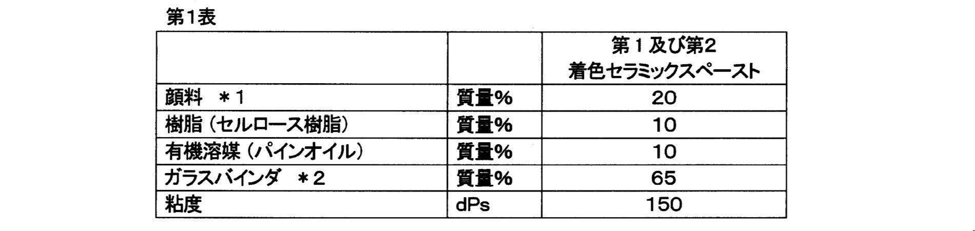
*2,主成分:ホウケイ酸ビスマス、ホウケイ酸亜鉛
次に、ウインドシールドの製造方法について説明する。まず、ガラス板の製造ラインについて説明する。
次に、ヘッドアップディスプレイ装置について説明する。ヘッドアップディスプレイ装置(HUD装置という)は、ウインドシールドに、車速等の情報を投射するものである。しかしながら、このHUD装置を用いると、ウインドシールドに投影された光により、二重像が形成されることが知られている。すなわち、ウインドシールドの内面で反射することで視認される像と、ウインドシールドの外面で反射することで視認される像とが別々に視認されるため、像が二重になっていた。
本実施形態に係るウインドシールドによれば、次のような効果を得ることができる。

以上、本発明の一実施形態について説明したが、本発明は上記実施形態に限定されるものではなく、その趣旨を逸脱しない限りにおいて、種々の変更が可能である。そして、以下に示す複数の変形例は適宜組合わせることが可能である。
上記実施形態では、外側ガラス板1と内側ガラス板2は、トップ面同士が対向するように配置しているが、これに限定されない。例えば、ボトム面同士が対向するように配置することもできる。また、トップ面とボトム面とが対向するように配置することもできる。この場合、外側ガラス板1のトップ面を中間膜3と対向させてもよいし、あるいは、内側ガラス板2のトップ面を中間膜3と対向させてもよい。
上記実施形態では、外側ガラス板1と内側ガラス板2の筋目150,250同士が一致しているが、外側ガラス板1の全ての筋目150の位置と内側ガラス板2の全ての筋目250の位置が、必ずしも一致していなくてもよく、このうちのいくつかが一致していればよい。但し、一致している筋目150,250は多い方がよく、例えば、50%以上が一致していることが好ましい。なお、ここでいう一致とは、完全な一致でなくてもよく、多少であれば、ずれていてもよい。さらに、外側ガラス板1の筋目150のピッチと内側ガラス板2の筋目250のピッチとは、完全に同じでなくてもよく、一部が同じであってもよい。
上記実施形態では、中間膜3が楔形に形成されているが、第1面301と第2面302とが平行な平板状に形成することもできる。
遮蔽層4の形状は特には限定されず、種々の形状が可能である。例えば、センサによる光の照射やカメラによる外部の撮影が可能なように、窓(開口)を設けた遮蔽層を形成することもできる。
外側ガラス板1、内側ガラス板2、中間膜3を楔形状に形成する方法は、特には限定されず、上述した方法以外でも可能である。
外側ガラス板と内側ガラス板の筋目がともに水平方向に延び、筋目が概ね一致するようにした。
外側ガラス板と内側ガラス板の筋目がともに水平方向に延び、筋目が上下方向にずれるようにした。具体的には、外側ガラス板の筋目の凸と、内側ガラス板の筋目の凹が概ね一致するようにした。
外側ガラス板の筋目が水平方向に延び、内側ガラス板の筋目が垂直方向に延びるようにした。すなわち、外側ガラス板の筋目と内側ガラス板の筋目が直交するようにした。
・投影像の歪みが全く見えない:A
・投影像の歪みがほとんど見えない:B
・投影像の歪みが弱く見える:C
・投影像の歪みが明らかに見える:D
結果は、以下の通りである。
・実施例2 A
・参考例 C
以下、本発明に係るウインドシールドの第2実施形態について説明する。以下では、主として第1実施形態との相違点について説明し、同じ構成については特に断りのない限り、説明を省略する。
本実施形態においては、外側ガラス板1及び内側ガラス板2の少なくとも一方が楔形に形成されていればよい。
本実施形態に係る中間膜3は、楔形に形成されている。中間膜3において、楔形を形成するための第1面301と第2面302とのなす楔角α3は、特には限定されないが、外側ガラス板1の楔角α1よりも小さくなっている。楔角α3の具体的な数値は、第1実施形態と同じである。
次に、ウインドシールドの製造方法について説明する。まず、ガラス板の製造ラインについて説明する。
本実施形態に係るウインドシールドによれば、次のような効果を得ることができる。
(1)第1実施形態で示した特徴の(2)と同様の効果を得ることができる。但し、上記表2の楔角は一例であり、外側ガラス板1及び内側ガラス板2の少なくとも一方が楔形であればよく、例えば、外側ガラス板1を平板状にし、内側ガラス板2を楔形にすることもできる。また、ウインドシールドの楔角αXは、例えば、0.2~0.7mradとすることができる。
以上、本発明の第2実施形態について説明したが、本発明は上記実施形態に限定されるものではなく、その趣旨を逸脱しない限りにおいて、種々の変更が可能である。そして、以下に示す複数の変形例は適宜組合わせることが可能である。
第1実施形態の変形例で示した<9-1>、<9-4>、<9-5>は、本実施形態の変形例としても適用することができる。
第2実施形態では、外側ガラス板1と内側ガラス板2の筋目同士が直交するようにしているが、平行にすることもできる。この場合、筋目が水平方向(上辺11、21及び下辺12、22と平行)に延びるようにすることができる。
以下、本発明に係るウインドシールドの第3実施形態について説明する。以下では、主として第2実施形態との相違点について説明し、同じ構成については特に断りのない限り、説明を省略する。
外側ガラス板1は、楔形に形成されている。外側ガラス板1の楔形を形成するための第1面101と第2面102とのなす楔角α1は、特には限定されないが、例えば、0.1~1.1mradとすることができ、0.15~1.05mradとすることができる。具体的には、例えば、(0.2+0.4n)±0.05mrad(但し、nは0以上の整数)とすることができる。
中間膜3は、上端面311から下端面312にいくにしたがって、厚みが小さくなるような楔形、あるいは中間膜3は、第1面301と第2面302とが平行な平板状に形成することができる。中間膜3を楔形にする場合、第1面301と第2面302とのなす楔角α3の具体的な数値は、第1実施形態で示したとおりである。なお、本実施形態では、内側ガラス板2と中間膜3の少なくとも一方が、楔形に形成されている。
本実施形態に係るウインドシールドによれば、次のような効果を得ることができる。
(1)外側ガラス板1、内側ガラス板2、及び中間膜3の楔角を調整することができるため、種々の楔角のウインドシールドを形成することができる。図2の例と同様に図18(a)の例では、外側ガラス板1と中間膜3とを楔形に形成しているが、これら外側ガラス板1と中間膜3の楔角α1,α3を調整することで、ウインドシールドの楔角αXを調整することができる。これに加え、図18(b)に示すように、内側ガラス板2も楔形に形成すると、さらに大きい楔角αXのウインドシールドを形成することができる。なお、外側ガラス板1と内側ガラス板2の楔角α1,α2は相違していてもよい。

以上、本発明の第2実施形態について説明したが、本発明は上記実施形態に限定されるものではなく、その趣旨を逸脱しない限りにおいて、種々の変更が可能である。そして、以下に示す複数の変形例は適宜組合わせることが可能である。
上記実施形態では、外側ガラス板1を楔形にし、内側ガラス板2及び中間膜3の少なくとも一方を楔形にしているが、例えば、内側ガラス板2を楔形にし、外側ガラス板1及び中間膜3の少なくとも一方を楔形にしてもよい。この場合、本発明の第1ガラス板が内側ガラス板2に相当し、第2ガラス板が外側ガラス板1に相当する。
第1実施形態の変形例で示した<9-1>、<9-4>、<9-5>、及び第2実施形態の変形例で示した<5-2>は、本実施形態の変形例としても適用することができる。
2 内側ガラス板(第2ガラス板)
3 中間膜
Claims (22)
- 第1面及び第2面を有する第1ガラス板と
第1面及び第2面を有し、当該第1面と前記第1ガラス板の第2面とが対向するように配置される、第2ガラス板と、
第1面及び第2面を有し、前記第1ガラス板と第2ガラス板との間に挟持される中間膜と、
を備え、
前記第1ガラス板及び前記第2ガラス板は、それぞれ、第1端部及び当該第1端部と対向する第2端部を有し、
前記中間膜は、第1端部及び当該第1端部と対向する第2端部を有し、
前記第1ガラス板は、前記第1端部から第2端部に向かって厚みが薄くなるように断面が楔形に形成され、
前記第1ガラス板及び前記第2ガラス板には、当該第1ガラス板及び当該第2ガラス板が車両に取り付けられたときに、水平方向に延びる複数の筋目が、それぞれ形成されている、ウインドシールド。 - 前記第1ガラス板に形成されている前記複数の筋目のうちの少なくとも1つの位置が、前記第2ガラス板に形成されている前記複数の筋目のいずれかの位置と略一致する、請求項1に記載のウインドシールド。
- 前記第1ガラス板に形成されている前記複数の筋目のピッチと、前記第2ガラス板に形成されている前記複数の筋目のピッチとが略同じである、請求項1または2に記載のウインドシールド。
- 前記第1ガラス板及び前記第2ガラス板は、フロート法により製造され、それぞれ、前記第1面及び前記第2面における酸化スズの濃度が相違しており、
前記第1ガラス板及び第2ガラス板は、前記酸化スズ濃度の低い面同士が、互いに対向するように配置されている、請求項1から3のいずれかに記載のウインドシールド。 - 前記第1ガラス板及び前記第2ガラス板は、フロート法により製造され、それぞれ、前記第1面及び前記第2面における酸化スズの濃度が相違しており、
前記第1ガラス板及び第2ガラス板は、前記酸化スズ濃度の低い面と前記酸化スズ濃度の高い面とが、互いに対向するように配置されている、請求項1から3のいずれかに記載のウインドシールド。 - 前記第2ガラス板は、前記第1端部から第2端部に向かって厚みが薄くなるように断面が楔形に形成されており、
前記第1ガラス板の楔角と、前記第2ガラス板の楔角とが略同一である、請求項1から5のいずれかに記載のウインドシールド。 - 前記第2ガラス板は、前記第1端部から第2端部に向かって厚みが薄くなるように断面が楔形に形成されており、
前記第1ガラス板の楔角と、前記第2ガラス板の楔角とが相違している、請求項1から5のいずれかに記載のウインドシールド。 - 前記中間膜は、前記第1端部から第2端部に向かって厚みが薄くなるように断面が楔形に形成されている、請求項1から7のいずれかに記載のウインドシールド。
- 前記中間膜は、前記第2端部から第1端部に向かって厚みが薄くなるように断面が楔形に形成されている、請求項1から7のいずれかに記載のウインドシールド。
- 前記第1ガラス板の楔角は、0.1~0.7mradであり、
前記中間膜の楔角は、0.02~0.18mradである、請求項8または9に記載のウインドシールド。 - 前記第1ガラス板の楔角は、0.15~0.45mradであり、
前記中間膜の楔角は、0.05~0.15mradである、請求項8または9に記載のウインドシールド。 - 前記第1ガラス板の前記第1面と前記第2面とが楔角α1をなすように形成され、
前記中間膜は、前記第1端部から第2端部に向かって厚みが薄くなり、前記第1面と前記第2面とが楔角α3をなすように形成され、
前記楔角α1が、前記楔角α3より大きい、請求項1に記載のウインドシールド。 - 前記第2ガラス板の前記第1面と前記第2面とが楔角α2をなすように形成されている、請求項12に記載のウインドシールド。
- 前記第1ガラス板の第1端部と、前記中間膜の第2端部とが同じ側に配置されている、請求項12または13に記載のウインドシールド。
- 前記第1ガラス板の第1端部と、前記中間膜の第1端部とが同じ側に配置されている、請求項12または13に記載のウインドシールド。
- 前記第2ガラス板及び前記中間膜の少なくとも一方は、前記第1端部から第2端部に向かって厚みが薄くなるように断面が楔形に形成されている、請求項1に記載のウインドシールド。
- 前記中間膜は、断面が楔形に形成され、
前記中間膜の第1端部と前記第1ガラス板の第1端部と同じ側に配置されている、請求項16に記載のウインドシールド。 - 前記第2ガラス板は、断面が楔形に形成され、
前記第1ガラス板の楔角が、前記第2ガラス板の楔角よりも大きい、請求項16または17に記載のウインドシールド。 - 前記第1ガラス板の前記楔角と、前記第2ガラス板の前記楔角との差が、0.35~0.45mradである、請求項18に記載のウインドシールド。
- 前記第1ガラス板の前記楔角と、前記第2ガラス板の前記楔角との差が、0.75~0.85mradである、請求項18に記載のウインドシールド。
- 前記中間膜は、断面が楔形に形成され、
前記第1ガラス板の前記楔角が、(0.2+0.4n)±0.05mradであり(但し、nは0以上の整数)、
前記中間膜の楔角が、0.05~0.15radである、請求項16から20のいずれかに記載のウインドシールド。 - 上辺の厚みが下辺の厚みよりも大きい、請求項1から21のいずれかに記載のウインドシールド。
Priority Applications (4)
| Application Number | Priority Date | Filing Date | Title |
|---|---|---|---|
| JP2022510555A JPWO2021193647A1 (ja) | 2020-03-23 | 2021-03-23 | |
| EP21774011.7A EP4129943A4 (en) | 2020-03-23 | 2021-03-23 | WINDSHIELD |
| US17/914,107 US20240208304A1 (en) | 2020-03-23 | 2021-03-23 | Windshield |
| CN202180023826.8A CN115335343A (zh) | 2020-03-23 | 2021-03-23 | 挡风玻璃 |
Applications Claiming Priority (6)
| Application Number | Priority Date | Filing Date | Title |
|---|---|---|---|
| JP2020051932 | 2020-03-23 | ||
| JP2020-051933 | 2020-03-23 | ||
| JP2020051933 | 2020-03-23 | ||
| JP2020-051934 | 2020-03-23 | ||
| JP2020051934 | 2020-03-23 | ||
| JP2020-051932 | 2020-03-23 |
Publications (1)
| Publication Number | Publication Date |
|---|---|
| WO2021193647A1 true WO2021193647A1 (ja) | 2021-09-30 |
Family
ID=77892202
Family Applications (1)
| Application Number | Title | Priority Date | Filing Date |
|---|---|---|---|
| PCT/JP2021/012023 Ceased WO2021193647A1 (ja) | 2020-03-23 | 2021-03-23 | ウインドシールド |
Country Status (5)
| Country | Link |
|---|---|
| US (1) | US20240208304A1 (ja) |
| EP (1) | EP4129943A4 (ja) |
| JP (1) | JPWO2021193647A1 (ja) |
| CN (1) | CN115335343A (ja) |
| WO (1) | WO2021193647A1 (ja) |
Cited By (2)
| Publication number | Priority date | Publication date | Assignee | Title |
|---|---|---|---|---|
| WO2023079991A1 (ja) * | 2021-11-08 | 2023-05-11 | Agc株式会社 | 楔形ガラスの製造方法 |
| US20250011216A1 (en) * | 2021-11-23 | 2025-01-09 | Corning Incorporated | Systems and methods for glass streak improvement via high resolution heating |
Citations (4)
| Publication number | Priority date | Publication date | Assignee | Title |
|---|---|---|---|---|
| JP2009035444A (ja) * | 2007-08-01 | 2009-02-19 | Nippon Sheet Glass Co Ltd | ウインドシールドおよびウインドシールド用中間膜 |
| JP2017105665A (ja) | 2015-12-08 | 2017-06-15 | 旭硝子株式会社 | 合わせガラス |
| WO2019124374A1 (ja) * | 2017-12-19 | 2019-06-27 | 積水化学工業株式会社 | 合わせガラス |
| WO2019131800A1 (ja) * | 2017-12-28 | 2019-07-04 | 日本板硝子株式会社 | ウインドシールド |
Family Cites Families (9)
| Publication number | Priority date | Publication date | Assignee | Title |
|---|---|---|---|---|
| EP3252022B1 (en) * | 2015-01-26 | 2021-03-10 | AGC Inc. | Laminated glass |
| KR102501344B1 (ko) * | 2015-07-31 | 2023-02-17 | 세키스이가가쿠 고교가부시키가이샤 | 합판 유리용 중간막, 합판 유리용 중간막의 제조 방법, 및 합판 유리 |
| CN108349800A (zh) * | 2015-11-24 | 2018-07-31 | 旭硝子株式会社 | 夹层玻璃 |
| JP6770470B2 (ja) * | 2017-03-27 | 2020-10-14 | 日本板硝子株式会社 | ウインドシールド |
| CN110636994B (zh) * | 2017-05-23 | 2022-11-01 | Agc株式会社 | 夹层玻璃 |
| EP3412448B1 (en) * | 2017-06-02 | 2021-07-07 | AGC Inc. | Laminated glass |
| CN109626848B (zh) * | 2017-10-05 | 2022-12-20 | Agc株式会社 | 夹层玻璃 |
| WO2019112018A1 (ja) * | 2017-12-07 | 2019-06-13 | Agc株式会社 | 車両用窓ガラス |
| DE102019002986A1 (de) * | 2018-05-07 | 2019-11-07 | AGC Inc. | Laminiertes glas |
-
2021
- 2021-03-23 EP EP21774011.7A patent/EP4129943A4/en not_active Withdrawn
- 2021-03-23 JP JP2022510555A patent/JPWO2021193647A1/ja active Pending
- 2021-03-23 US US17/914,107 patent/US20240208304A1/en active Pending
- 2021-03-23 CN CN202180023826.8A patent/CN115335343A/zh active Pending
- 2021-03-23 WO PCT/JP2021/012023 patent/WO2021193647A1/ja not_active Ceased
Patent Citations (4)
| Publication number | Priority date | Publication date | Assignee | Title |
|---|---|---|---|---|
| JP2009035444A (ja) * | 2007-08-01 | 2009-02-19 | Nippon Sheet Glass Co Ltd | ウインドシールドおよびウインドシールド用中間膜 |
| JP2017105665A (ja) | 2015-12-08 | 2017-06-15 | 旭硝子株式会社 | 合わせガラス |
| WO2019124374A1 (ja) * | 2017-12-19 | 2019-06-27 | 積水化学工業株式会社 | 合わせガラス |
| WO2019131800A1 (ja) * | 2017-12-28 | 2019-07-04 | 日本板硝子株式会社 | ウインドシールド |
Non-Patent Citations (1)
| Title |
|---|
| See also references of EP4129943A4 |
Cited By (2)
| Publication number | Priority date | Publication date | Assignee | Title |
|---|---|---|---|---|
| WO2023079991A1 (ja) * | 2021-11-08 | 2023-05-11 | Agc株式会社 | 楔形ガラスの製造方法 |
| US20250011216A1 (en) * | 2021-11-23 | 2025-01-09 | Corning Incorporated | Systems and methods for glass streak improvement via high resolution heating |
Also Published As
| Publication number | Publication date |
|---|---|
| JPWO2021193647A1 (ja) | 2021-09-30 |
| EP4129943A1 (en) | 2023-02-08 |
| US20240208304A1 (en) | 2024-06-27 |
| EP4129943A4 (en) | 2024-05-01 |
| CN115335343A (zh) | 2022-11-11 |
Similar Documents
| Publication | Publication Date | Title |
|---|---|---|
| JP6938366B2 (ja) | ウインドシールド | |
| JP6770470B2 (ja) | ウインドシールド | |
| JP7436254B2 (ja) | ウインドシールド、及びウインドシールドの製造方法 | |
| CN105980325B (zh) | 夹层玻璃 | |
| JP7018767B2 (ja) | ウインドシールド | |
| CN107207338A (zh) | 夹层玻璃 | |
| WO2019131803A1 (ja) | ウインドシールド | |
| JPWO2020116586A1 (ja) | 自動車用合わせガラス | |
| JP2023115054A (ja) | 車両用ドアガラス | |
| WO2019107458A1 (ja) | 合わせガラス | |
| WO2021193647A1 (ja) | ウインドシールド | |
| JP7160091B2 (ja) | 車両用フロントガラス | |
| JP6945443B2 (ja) | ガラス板モジュール | |
| JP2021147019A (ja) | ウインドシールド、及びその製造方法 | |
| JP7685643B2 (ja) | 合わせガラス | |
| JP7685644B2 (ja) | 合わせガラス | |
| JP4371654B2 (ja) | 合わせガラス用中間膜及び合わせガラス。 | |
| JP7602975B2 (ja) | ウインドシールド |
Legal Events
| Date | Code | Title | Description |
|---|---|---|---|
| 121 | Ep: the epo has been informed by wipo that ep was designated in this application |
Ref document number: 21774011 Country of ref document: EP Kind code of ref document: A1 |
|
| ENP | Entry into the national phase |
Ref document number: 2022510555 Country of ref document: JP Kind code of ref document: A |
|
| WWE | Wipo information: entry into national phase |
Ref document number: 17914107 Country of ref document: US |
|
| NENP | Non-entry into the national phase |
Ref country code: DE |
|
| ENP | Entry into the national phase |
Ref document number: 2021774011 Country of ref document: EP Effective date: 20221024 |