WO2021193726A1 - 複合紙糸、複合紙糸製造装置、および複合紙糸製造方法 - Google Patents
複合紙糸、複合紙糸製造装置、および複合紙糸製造方法 Download PDFInfo
- Publication number
- WO2021193726A1 WO2021193726A1 PCT/JP2021/012266 JP2021012266W WO2021193726A1 WO 2021193726 A1 WO2021193726 A1 WO 2021193726A1 JP 2021012266 W JP2021012266 W JP 2021012266W WO 2021193726 A1 WO2021193726 A1 WO 2021193726A1
- Authority
- WO
- WIPO (PCT)
- Prior art keywords
- paper
- yarn
- thread
- composite
- paper tape
- Prior art date
- Legal status (The legal status is an assumption and is not a legal conclusion. Google has not performed a legal analysis and makes no representation as to the accuracy of the status listed.)
- Ceased
Links
Images


Classifications
-
- D—TEXTILES; PAPER
- D02—YARNS; MECHANICAL FINISHING OF YARNS OR ROPES; WARPING OR BEAMING
- D02G—CRIMPING OR CURLING FIBRES, FILAMENTS, THREADS, OR YARNS; YARNS OR THREADS
- D02G3/00—Yarns or threads, e.g. fancy yarns; Processes or apparatus for the production thereof, not otherwise provided for
- D02G3/02—Yarns or threads characterised by the material or by the materials from which they are made
- D02G3/08—Paper yarns or threads
-
- D—TEXTILES; PAPER
- D01—NATURAL OR MAN-MADE THREADS OR FIBRES; SPINNING
- D01D—MECHANICAL METHODS OR APPARATUS IN THE MANUFACTURE OF ARTIFICIAL FILAMENTS, THREADS, FIBRES, BRISTLES OR RIBBONS
- D01D5/00—Formation of filaments, threads, or the like
- D01D5/42—Formation of filaments, threads, or the like by cutting films into narrow ribbons or filaments or by fibrillation of films or filaments
- D01D5/426—Formation of filaments, threads, or the like by cutting films into narrow ribbons or filaments or by fibrillation of films or filaments by cutting films
-
- D—TEXTILES; PAPER
- D01—NATURAL OR MAN-MADE THREADS OR FIBRES; SPINNING
- D01H—SPINNING OR TWISTING
- D01H1/00—Spinning or twisting machines in which the product is wound-up continuously
- D01H1/11—Spinning by false-twisting
-
- D—TEXTILES; PAPER
- D01—NATURAL OR MAN-MADE THREADS OR FIBRES; SPINNING
- D01H—SPINNING OR TWISTING
- D01H13/00—Other common constructional features, details or accessories
- D01H13/04—Guides for slivers, rovings, or yarns; Smoothing dies
-
- D—TEXTILES; PAPER
- D02—YARNS; MECHANICAL FINISHING OF YARNS OR ROPES; WARPING OR BEAMING
- D02G—CRIMPING OR CURLING FIBRES, FILAMENTS, THREADS, OR YARNS; YARNS OR THREADS
- D02G3/00—Yarns or threads, e.g. fancy yarns; Processes or apparatus for the production thereof, not otherwise provided for
- D02G3/22—Yarns or threads characterised by constructional features, e.g. blending, filament/fibre
- D02G3/36—Cored or coated yarns or threads
-
- D—TEXTILES; PAPER
- D02—YARNS; MECHANICAL FINISHING OF YARNS OR ROPES; WARPING OR BEAMING
- D02G—CRIMPING OR CURLING FIBRES, FILAMENTS, THREADS, OR YARNS; YARNS OR THREADS
- D02G3/00—Yarns or threads, e.g. fancy yarns; Processes or apparatus for the production thereof, not otherwise provided for
- D02G3/22—Yarns or threads characterised by constructional features, e.g. blending, filament/fibre
- D02G3/38—Threads in which fibres, filaments, or yarns are wound with other yarns or filaments, e.g. wrap yarns, i.e. strands of filaments or staple fibres are wrapped by a helically wound binder yarn
- D02G3/385—Threads in which fibres, filaments, or yarns are wound with other yarns or filaments, e.g. wrap yarns, i.e. strands of filaments or staple fibres are wrapped by a helically wound binder yarn using hollow spindles, e.g. making coverspun yarns
Definitions
- the present invention relates to a yarn (hereinafter referred to as "composite paper yarn") formed by combining one or more kinds of yarns selected from the group consisting of long fibers and spun yarns and a paper tape, and a composite paper yarn.
- composite paper yarn formed by combining one or more kinds of yarns selected from the group consisting of long fibers and spun yarns and a paper tape, and a composite paper yarn.
- the present invention relates to a manufacturing apparatus and a method for manufacturing a composite paper yarn.
- the paper thread is made by slitting a sheet of paper to a width of about several mm and twisting the paper tape formed by the slits into a thread.
- sheet-shaped paper is slit into widths of various sizes by a slitter, and one paper tape contained in each of the formed multiple paper tapes is wound into cheese or cones. Then I wound it up and got a winding body.
- a conventional twisted yarn maker selects a wound body in which paper tape of a required width is wound, sets the paper tape in a covering machine, and twists the paper tape together with long fibers made of synthetic fibers or the like, or paper tape.
- Composite paper yarn was manufactured by covering long fibers and the like. Covering refers to a process in which long fibers or the like are wound around a core yarn or the like in a coil shape to manufacture a covering yarn.
- a covering yarn in which long fibers or spun yarns are wound around the outer circumference of paper tape can be said to be a kind of composite paper yarn.
- the surface of the portion already wound by the thread has irregularities due to the thread.
- the portion further wound by the thread fits into the recess formed between the portions already wound by the thread. Therefore, when the yarn is wound, the yarn is hardly unwound.
- the paper tape is wound, the paper tape is in the form of a flat tape, and the surface of the portion already wound by the paper tape has almost no unevenness, and the paper tape is slippery on this surface. For this reason, when the paper tape is wound and wound around cheese or cone, or when the wound paper tape is stored, or when the paper tape is unwound from the wound body to produce a composite paper thread. Occasionally, the paper tape may collapse.
- narrow paper tapes with a width of about 1 mm to about 2 mm are not only prone to roll collapse, but also have a small breaking elongation of the narrow paper tapes, so the paper tape breaks with a slight impact when it is wound up. It tends to end up. Therefore, conventionally, with narrow paper tape, winding is not stable, it is very difficult to handle, and the paper tape is easily cut when it is wound or pulled out from the winding body, resulting in a large amount of material loss and unstable quality. It was difficult to manufacture with.
- the elongation at break is defined as the elongation at break (tensile elongation) when the sample is pulled at a speed of 200 mm / min using a tensile tester according to ASTM-D-882 or JIS-C-2151. ).
- tensile elongation 100 ⁇ (LL 0 ) / L. It is calculated by the formula of " 0".
- the inventor of the present application directly uses the formed paper tape instead of winding the paper tape formed by slitting the paper sheet with a slitter and then using it for manufacturing a composite paper thread as in the conventional case.
- a paper sheet is slit with a slitter, about 100 to 200 paper tapes are made from one paper sheet.
- each one paper tape included in the plurality of paper tapes is supplied so that one paper tape is supplied for each one weight covering unit.
- one paper tape is conveyed over a distance of at least about 15 m. Need arises.
- the paper tape may be cut due to its own weight.
- the inventor of the present application obtained the following findings in the process of further experimenting with the prototype for practical use. It was found that in the conventional method of manufacturing a covering yarn using paper tape, a slight impact is generated on each paper tape in the process of feeding one paper tape for each covering unit of one weight. .. Paper tape that is thin, thin, and has a low breaking elongation tends to be easily cut by this slight impact, but it has been found that it has a certain degree of breaking strength against a static load.
- the breaking strength is a tensile load value when a sample is pulled at a speed of 200 mm / min using a tensile tester according to ASTM-D-882 or JIS-C-2151 and the sample breaks. ..
- a Japanese paper tape having a basis weight of 10 g / mm 2 and a width of 1.2 mm had an average breaking strength of 69.0 gf (0.68 N) and an average breaking elongation of 1.25%.
- a Japanese paper tape having a basis weight of 12 g / mm 2 and a width of 1.2 mm had an average breaking strength of 94.5 gf (0.93N) and an average breaking elongation of 1.25%.
- a Japanese paper tape having a basis weight of 10 g / mm 2 and a width of 1.5 mm had an average breaking strength of 96.5 gf (0.95 N) and an average breaking elongation of 1.88%. In each case, the length of the sample was 200 mm.
- the tension was measured from 3 gf (0.029N) to 10 g (0.098N), but the Japanese paper tape was frequently cut and the operating rate of the paper thread manufacturing equipment was 40% to 60%. It was low.
- the average breaking strength of the Japanese paper tape is about 70 gf (about 0.69 N)
- the reason why the Japanese paper tape is cut at a tension of 3 gf to 10 gf is that the average breaking elongation of the Japanese paper tape is small.
- the inventor thought. Therefore, as a result of observing the process from the formation of each Japanese paper tape to the supply to the covering unit, the inventor of the present application found that the Japanese paper tape was cut when a slight impact was applied in the feeding direction. I found it. As a result of investigating the cause of the slight impact, the inventor of the present application has come to create the present invention.
- An object of the present invention is that when one paper tape contained in a plurality of paper tapes formed by slitting a paper sheet with a slitter is continuously supplied to a covering machine as it is and processed into a composite paper thread, each of them. It is an object of the present invention to provide a novel composite paper thread manufacturing apparatus and a composite paper thread manufacturing method provided with a mechanism that does not give a slight impact in the feeding direction, that is, a sudden change in tension, to one paper tape.
- the inventor of the present application pulled the composite paper yarn obtained by the novel composite paper yarn manufacturing apparatus and the composite paper yarn manufacturing method to perform a measurement test of breaking strength, and found that the paper portion of the composite paper yarn (Japanese paper only). ) was found to be difficult to cut.
- the composite paper thread manufactured by the conventional paper thread manufacturing apparatus is pulled, the long fiber portion made of synthetic fibers cannot be cut, but the paper portion is often cut.
- a woven fabric or knitted fabric is made into a woven fabric or knitted fabric using a composite paper thread in which the paper part is cut, the cut paper part may be unraveled and appear on the surface of the product.
- the composite paper thread manufacturing apparatus is compared with a pair of delivery rollers that sandwich one paper tape and deliver it at a constant speed, and a constant speed of the pair of delivery rollers.
- a pair of driving rollers that can be rotated at a surface speed exceeding 1,000 times, hold the one paper tape, and feed the one paper tape while sliding the driving roller against the one paper tape. It has a slip roller and a false twisting mechanism in which a first thread is attached to the one paper tape sent out by the pair of slip rollers and false twisted, and a twisting region or untwisting of the false twisting mechanism.
- Covering provided with a one-weight covering unit having a covering mechanism for covering the second thread on the one paper tape and the first thread attached to the one paper tape in the region.
- the first thread is composed of a first long fiber, a first spun yarn, and a composite yarn in which the first long fiber and the first spun yarn are combined. It is at least one yarn selected from the group, and the second yarn is a second long fiber, a second spun yarn, and the second long fiber and the second spun yarn.
- a composite paper yarn manufacturing apparatus which is at least one yarn selected from the group consisting of combined composite yarns.
- a paper roll in which a long paper sheet is wound into a roll and the paper sheet unwound from the paper roll are slit to feed the paper sheet. It has been conveyed by a slitter that forms a plurality of narrow paper tapes, a pair of delivery rollers that sandwich the plurality of paper tapes formed by the slitter and feed the paper tapes at a constant speed, and the pair of delivery rollers.
- a distributor which has a plurality of guide paths provided so as to allow only one paper tape to pass from the plurality of paper tapes and distributes the plurality of paper tapes for each of the one paper tapes, and the pair.
- a drive roller that is rotated at a surface speed exceeding 1.000 times the constant speed of the delivery roller, sandwiches the one paper tape distributed by the distributor, and holds the drive roller of the one.
- a plurality of pair of slip rollers that feed out the one paper tape while slipping on the paper tape are provided so as to correspond to the pair of slip rollers for each of the one paper tape distributed from the plurality of paper tapes. It has a plurality of pairs of slip rollers and a false twisting mechanism in which a first thread is attached to the one paper tape sent out by the pair of slip rollers and false twisted, and the false twisting mechanism is twisted.
- the one-weight covering unit having a covering mechanism for covering the one paper tape and the first thread attached to the one paper tape with the second thread in the region or the untwisted region is described as described above.
- Each of the one paper tapes sent out by the pair of slip rollers is provided with a covering machine provided with a plurality of weights so that the one weight covering unit corresponds to the one paper tape, and the first thread is the first.
- the second yarn selected from the group consisting of the long fibers of the above, the first spun yarn, and the composite yarn in which the first long fibers and the first spun yarn are combined.
- the thread is at least one selected from the group consisting of a second long fiber, a second spun yarn, and a composite yarn in which the second long fiber and the second spun yarn are combined. It is a composite paper thread manufacturing apparatus that is a thread.
- the surface speed of the drive roller in the pair of slip rollers is 1.005 times or more and 1.050 times or less as compared with the feed speed of the pair of feed rollers. obtain.
- the one paper tape that is falsely twisted with the at least one first yarn as compared with the feed rate of the at least one first yarn can be 1.05 times or more and 1.35 times or less.
- the pair of slip rollers includes the driving roller and the driven roller, and the at least one roller selected from the group consisting of the driving roller and the driven roller
- the surface of the roller may be smoothed against paper.
- the drive roller and the driven roller are arranged in the vertical direction, and the drive roller is arranged below the driven roller.
- the driven roller may be disposed above the driving roller.
- the driven rollers may be arranged so as to be arbitrarily changeable to rollers having different weights.
- the composite paper thread manufacturing method includes a step of feeding out one paper tape, a step of feeding out the one paper tape while slipping, and a first step of feeding the one paper tape while slipping.
- the first yarn is composed of a group consisting of a first long fiber, a first spun yarn, and a composite yarn in which the first long fiber and the first spun yarn are combined.
- At least one selected yarn, the second yarn is a combination of a second long fiber, a second spun yarn, and the second long fiber and the second spun yarn.
- the composite paper thread manufacturing method includes a step of preparing a paper sheet wound into a roll, a step of feeding the paper sheet in the longitudinal direction, and a step of feeding the fed paper sheet.
- the step of false twisting each of the single paper tapes sent out while slipping with a first thread and the step of false twisting, the twisting region or untwisting.
- the region comprises a step of covering the second thread for each of the one paper tape and the first thread, wherein the first thread is a first long fiber, a first. It is at least one yarn selected from the group consisting of a spun yarn and a composite yarn in which the first long fiber and the first spun yarn are combined, and the second yarn is a second yarn.
- a composite paper yarn which is at least one yarn selected from the group consisting of a long fiber, a second spun yarn, and a composite yarn in which the second long fiber and the second spun yarn are combined. It is a manufacturing method.
- the composite paper thread according to the present invention may be a composite paper thread manufactured by the composite paper thread manufacturing apparatus according to the present invention.
- the composite paper thread according to the present invention is a composite paper thread manufactured by the composite paper thread manufacturing apparatus according to the present invention, and is formed when the composite paper thread is cut to a predetermined length.
- the length of the one paper tape contained in the section of the composite paper thread is 1.05 times or more and 1.35 times or less as compared with the length of the first thread contained in the section of the composite paper thread. It can be a composite paper thread.
- the second thread is covered with a fiber bundle in which one paper tape and the first thread attached to the one paper tape are falsely twisted.
- the composite paper is a composite paper yarn, which is compared with the length of the first thread included in the section of the composite paper yarn formed when the composite paper yarn is cut to a predetermined length. It can be a composite paper thread in which the length of the one paper tape included in the section of the thread is 1.05 times or more and 1.35 times or less.
- the distributor in the composite paper thread manufacturing apparatus according to the present invention is provided with a plurality of guide paths so that one guide path corresponds to each one paper tape included in the plurality of paper tapes. Is preferable.
- the first thread is at least one of the first long fibers. Is preferable, and one of the first long fibers is more preferable.
- the second thread is at least one said second long fiber. Is preferable, and one of the second long fibers is more preferable.
- one paper tape is fed at a constant speed by a pair of feeding rollers, and the surface speed is faster than the speed of the one paper tape.
- a pair of rotating slip rollers are configured to slide one paper tape and send it to one covering unit.
- the drive rollers of the pair of slip rollers have a surface speed of more than 1.000 times, preferably 1.005 times or more and 1.050 times or less, more preferably 1 of the delivery speed (constant speed) of the delivery rollers. It is rotated at a surface speed of .008 times or more and 1.025 times or less.
- the feed rate of the pair of slip rollers refers to the surface speed of the drive rollers.
- the paper sheet unwound from the paper roll is slit by a slitter to form a plurality of paper tapes.
- the formed plurality of paper tapes are fed out at a constant speed by a pair of feeding rollers.
- the plurality of paper tapes sent out are distributed to each paper tape by a distributor.
- One distributed paper tape is supplied to each of the covering units of one weight via a pair of slip rollers.
- the drive rollers of the pair of slip rollers have a surface speed of more than 1.000 times, preferably 1.005 times or more and 1.050 times or less, more preferably 1 of the delivery speed (constant speed) of the delivery rollers.
- the feed rate of the pair of slip rollers refers to the surface speed of the drive rollers.
- the feed rate of the pair of slip rollers is rotated at a surface speed of more than 1.000 times, preferably more than 1.005 times the feed rate of the delivery rollers, one paper tape is cut. Is almost gone. Each one paper tape is fed in a state of constantly slipping between a pair of slip rollers, and in most cases, a slight impact (a sudden change in tension) in the sudden feeding direction is given to each one paper tape. No.
- each one paper tape contained in a plurality of paper tapes into a composite paper thread is hardly cut, and one weight covering unit provided in the covering machine is provided.
- One paper tape can be smoothly supplied for each, and the composite paper thread is smoothly manufactured.
- the feed rate of the pair of feed rollers is 1.05 times or more and 1.35 times or less, preferably 1.10 times or more and 1.
- the feed rate of the pair of feed rollers is 1.05 times or more and 1.35 times or less, preferably 1.10 times or more and 1.
- the length of the paper tape becomes the first. It is easy to overfeed so that it is 1.05 times or more and 1.35 times or less the length of the thread.
- the composite paper thread obtained by overfeeding in this way when the first thread is pulled to the extent that it cannot be cut, only the paper portion (paper tape) is hardly cut. Since the paper tape is configured to be fed out by constantly applying a constant tension by a pair of slip rollers, the obtained composite paper yarn is evenly false-twisted and covered.
- the composite paper thread manufacturing apparatus and the composite paper thread according to the present invention are used.
- the manufacturing method a plurality of paper tapes formed by slitting a paper sheet are continuously distributed for each paper tape and false-twisted or covered to form a composite paper thread.
- paper tape can always be stably supplied by a pair of slip rollers, and one weight is used for each covering unit.
- the paper tape of the book, the first thread and the second thread can always be stably supplied. Therefore, the paper tape and the first yarn are likely to be falsely twisted evenly in the longitudinal direction, and are easily covered by the second yarn evenly in the longitudinal direction. Therefore, in the manufactured composite paper yarn according to the present invention, local unevenness is unlikely to occur in the longitudinal direction.
- the composite paper thread according to the present invention is included in the section of the composite paper thread as compared with the length of the first thread included in the section of the composite paper thread formed when cut to a predetermined length.
- the length of one paper tape is preferably 1.05 times or more and 1.35 times or less, more preferably 1.10 times or more and 1.20 times or less, still more preferably 1.14 times or more and 1. It is desirable that it is set to be 17 times or less, and even more preferably 1.145 times or more and 1.165 times or less.
- the composite paper yarn produced in this manner according to the present invention when the first yarn is pulled, the paper tape is stretched straight by the amount of overfeed, so that only the paper tape is almost cut. No. Since the composite paper yarn according to the present invention is twisted evenly in the longitudinal direction as described above, even if the composite paper yarn is locally pulled at a short distance, only the paper tape is hardly broken.
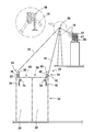
- FIG. 1 It is a figure which shows the schematic structure of the composite paper thread manufacturing apparatus which concerns on one Embodiment of this invention, (a) is a front view, (b) is a plan view. It is the schematic explanatory drawing of the slitter provided in the composite paper thread manufacturing apparatus which concerns on one Embodiment of this invention, (a) is a front view, (b) is a plan view. In the figure, a comb-shaped sensor attached to the slitter is also drawn. It is a side view which shows the Example of the pair of delivery rollers provided in the composite paper yarn manufacturing apparatus which concerns on one Embodiment of this invention.
- the composite paper yarn manufacturing apparatus 10 shows a Japanese paper roll 14, a slipter 16, a pair of delivery rollers 20, a distributor 21, and FIG. It is provided with a plurality of pairs of slip rollers 23 (see FIG. 6) and a covering machine 25.
- the Japanese paper roll 14 is a roll of a long Japanese paper sheet 12.
- the slitter 16 is arranged so as to slit the Japanese paper sheet 12 unwound from the Japanese paper roll 14 to form a plurality of Japanese paper tapes 17 in the feeding direction of the Japanese paper sheet 12.
- the pair of delivery rollers 20 are arranged so as to sandwich (nip) and convey a plurality of Japanese paper tapes 17.
- the distributor 21 distributes a plurality of Japanese paper tapes 17 delivered by the pair of sending rollers 20 to one Japanese paper tape 18.
- the plurality of pairs of slip rollers 23 shown in FIG. 6 are provided with a plurality of pairs of slip rollers 24 shown in FIG.
- Each pair of slip rollers 24 conveys each of the distributed Japanese paper tapes 18 while sandwiching (niping) them in a slipperable manner.
- the covering machine 25 shown in FIG. 1 is provided with a covering unit having a plurality of weights.
- each covering unit 26 includes a false twisting mechanism 81 in which a first thread 72 is attached to a single Japanese paper tape 18 sent from a pair of slip rollers 24 and falsely twisted.
- One Japanese paper tape 18 and the first thread 72 have a covering mechanism 82 that covers the second thread 70.
- the paper used in the present invention is not particularly limited to so-called Western paper or Japanese paper as long as it can be twisted and processed into a thread shape after being slit into a narrow width.
- the paper used in the present invention is preferably Japanese paper from the viewpoint of being thin, narrow and having high breaking strength.
- Washi is a paper made by straining a slurry of Japanese paper raw material whose main component is fiber, which is obtained by beating a raw material plant suitable for Japanese paper.
- raw material plants suitable for Japanese paper include one or more plants selected from the group consisting of kozo, mitsumata, ganpi, hemp, conifer, hardwood, and bamboo grass.
- the basis weight of Japanese paper is preferably within the range of about 8 g / m 2 or more and about 30 g / m 2 or less. Smaller ones can also be used.
- the Japanese paper used in the present invention may contain raw material fibers derived from other than the above-mentioned Japanese paper raw materials as long as it is 20% by mass or less.
- the Japanese paper used in the present invention preferably contains fibers derived from other than the above-mentioned Japanese paper raw materials in an amount of 20% by mass or less.
- the Japanese paper used in the present invention is more preferably one in which the content of fibers derived from the above-mentioned Japanese paper raw material is 90% by mass or more.
- the width and length of the Japanese paper sheet 12 used in the present invention are not particularly limited as long as it does not contradict the object of the present invention.
- the width of each of the Japanese paper tapes 18 is about 0.8 mm or more and about 30 mm or less, the orientation of the raw material fibers Compared to tape made of paper (Western paper) with random directions, it is less likely to break due to the tensile force in the longitudinal direction.
- the long Japanese paper sheet 12 is wound around a roller 27 in a roll shape to form a Japanese paper roll 14.
- the roller 27 is installed on a bearing (not shown) so that the Japanese paper sheet 12 can be smoothly fed out from the Japanese paper roll 14.
- the roller 27 or the bearing may be connected to a driving device (not shown), and the roller 27 may be rotated by the driving force of the driving device so that the Japanese paper sheet 12 can be smoothly fed out from the Japanese paper roll 14.
- the Japanese paper roll 14 may be placed on two rotating rolls parallel to each other, and the Japanese paper sheet 12 may be fed out from the Japanese paper roll 14 by rotating the two rotating rolls.
- it is preferable that the Japanese paper sheet 12 is sandwiched (nipped) by a pair of feeding rollers 28 shown in FIG. 1 connected to a drive device (not shown) so that the Japanese paper sheet 12 can be fed out from the Japanese paper roll 14.
- the slitter 16 includes a plurality of disc-shaped rotary blades 29 and a flat plate-shaped facing member 33 provided so that the cutting edges of the plurality of disc-shaped rotary blades 29 come into contact with each other or slightly bite into the slitter 16.
- the plurality of rotary blades 30 121 pieces of each rotary blade 30 included in the above are arranged at a pitch of 1.5 mm.
- Each rotary blade 30 has a blade having a sharp outer circumference formed of a thin steel plate having a razor shape or the like.
- the thickness of each rotary blade 30 is not limited, but for example, when the distance between the adjacent rotary blades 30 and the rotary blades 30 is 1.5 mm pitch, one between the adjacent rotary blades 30 and the rotary blades 30.
- the spacer 32 is interposed and adjusted.
- the plurality of rotary blades 29 are rotated by a drive device (not shown), and smoothly slit the Japanese paper sheet 12 conveyed between the plurality of rotary blades 29 and the facing member 33.
- the diameter of each rotary blade 30 is not particularly limited, but is preferably about 30 mm or more and 60 mm or less, for example.
- the facing member 33 is brought into contact with at least the cutting edges of the plurality of rotary blades 29, it is preferable that the facing member 33 is made of a resin material that does not easily wear the cutting edges.
- the facing member 33 may be entirely made of a resin material, or may be made of a resin material only at the upper portion where the cutting edges of the plurality of rotary blades 29 come into contact with each other.
- the shape of the facing member 33 may be a flat plate as shown in FIG. 2, but is not particularly limited. For example, when the shape of the facing member is a cylinder or a cylinder, the facing member can be configured to rotate together with the plurality of rotary blades 29.
- the rotary blade 30 is provided so that the width of each Japanese paper tape 18 is within a range of about 0.8 mm or more and about 30 mm or less.
- the pitch between the rotary blade 30 and the rotary blade 30 is set.
- the total of the thicknesses of the plurality of rotary blades 29 and the thicknesses of the plurality of spacers 31 corresponds to the width of the plurality of Japanese paper tapes 17. Therefore, when changing the width of each Japanese paper tape 18, the thickness of each spacer 32 included in the plurality of spacers 31 is changed.
- each rotary blade 30 and each spacer 32 are corresponding to 121 rotary blades 29 and 120 spacers 31. Will be arranged alternately.
- Each spacer 32 may be appropriately changed to one having an appropriate width according to the pitch between the rotary blade 30 and the rotary blade 30, and a spacer 32 having a constant width may be used.
- both side portions of the Japanese paper sheet 12 are treated as two ears 19 which are not included in the plurality of Japanese paper tapes 17.
- the width of each selvage portion in the two selvage portions 19 is preferably at least 3 mm or more and about 6 mm or less. It is preferable that both side portions of the Japanese paper sheet 12 are collected as two unnecessary ear portions 19 and recycled as a raw material for new Japanese paper.
- the interval at which the Japanese paper sheet 12 is slit by the slitter 16, that is, the width of each Japanese paper tape 18 included in the plurality of Japanese paper tapes 17 may be constant, but is not particularly limited. For example, it is possible to form a 1 mm wide Japanese paper tape and a 2 mm wide Japanese paper tape at the same time. In this case, two types of composite paper threads having different widths of the Japanese paper tape used are produced at the same time. Become.
- Paper dust suction device 34 From the viewpoint of avoiding the problem described below, it is preferable to provide the paper dust suction device 34 in the vicinity of the slitter 16.
- the paper dust suction device 33 can also be used when the cutting Japanese paper tape discharging device described later is a suction type.
- the paper dust suction device 34 also has a function of removing broken Japanese paper tape.
- the Japanese paper sheet 12 has holes such as pinholes
- the Japanese paper tape breaks at the place where the holes are formed.
- the paper dust suction device 34 sucks and removes such broken Japanese paper tape.
- Comb-shaped sensor It is preferable to provide a comb-shaped sensor 35 in the vicinity where the plurality of Japanese paper tapes 17 formed by the slitter 16 are sent out immediately after their formation. A plurality of comb-shaped sensors 35 are inserted between each of the one Japanese paper tapes 18 included in the plurality of Japanese paper tapes 17 and between the plurality of Japanese paper tapes 18 and the ears 19.
- the plate 36 of the above is provided.
- Each plate 37 included in the plurality of plates 36 preferably has a thickness of 0.1 mm or more and 0.5 mm or less, and is freely rotatably attached to one shaft.
- An optical sensor (not shown) is arranged on the side of the plurality of plates 36, and is configured to operate the optical sensor when at least one plate 37 of the plurality of plates 36 is rotated to block light.
- a plurality of Japanese paper tapes 17 are formed by slitting the Japanese paper sheet 12 with a slitter 16, but even if the adjacent Japanese paper tapes 18 are not completely separated from each other, the adjacent Japanese paper tapes 18 are formed by the plurality of plates 36. It can be completely separated from each other.
- the portion that is not slit is included in the plurality of plates 36.
- the comb-shaped sensor 35 When it hits any of the plates 37 and the hit plate 37 is rotated, the comb-shaped sensor 35 is activated and the composite Japanese paper thread manufacturing apparatus is stopped. When stopped in this way, the slitter 16 is replaced with a new one, or the distance between the cutting edges of the plurality of rotary blades 29 and the facing member 33 is adjusted, and then the composite Japanese paper thread manufacturing apparatus is restarted. It is preferable to let it.
- the Japanese paper sheet 12 unwound from the Japanese paper roll 14 is slit by the slitter 16.
- Each of the Japanese paper tapes 18 contained in the plurality of Japanese paper tapes 17 formed by the slits is fed at a constant speed by a pair of sending rollers 20. That is, the Japanese paper sheet 12 is pulled out from the Japanese paper roll 14 by the pair of sending rollers 20, and is slit by the slitter 16 in the process from the Japanese paper roll 14 to the sending roller 20.
- the plurality of Japanese paper tapes 17 formed by the slits and the two selvage portions 19 are sandwiched (nipped) by a pair of delivery rollers 20 and sent out. As shown in FIG.
- the pair of delivery rollers 20 are configured to be driven by a drive device 39 with a speed reducer.
- the surface of each roller 38 of the pair of sending rollers 20 is formed of rubber, resin, or the like. Is preferable.
- the rollers 38 are pressed by a spring or the like so that the rollers 38 can be brought into close contact with each other. The two ears 19 (see FIG. 2) delivered from the pair of delivery rollers 20 are collected and removed.
- the plurality of Japanese paper tapes 17 fed from the pair of feeding rollers 20 are formed. It is preferable to divide the bundle as shown in FIG. 1 (b), for example. For example, when 120 Japanese paper tapes 17 are formed from the Japanese paper sheet 12, it is preferable to divide the 120 Japanese paper tapes into three bundles of 40 sheets each. As an example of division, a bundle formed of 120 washi tapes 17 was pressed by a first pressing roller 40, 40 washi tapes 17 were taken out from the 120, and the remaining 80 washi tapes 17 were formed.
- a bundle is sent and pressed by a second pressing roller 41 to take out 40 Japanese paper tapes 17, and a bundle formed of the remaining 40 Japanese paper tapes 17 is sent and pressed by a third pressing roller 42 to press these 40 pieces. It is good to take it out.
- 120 Japanese paper tapes 17 may be divided into four bundles of 30 tapes each. How to divide the plurality of Japanese paper tapes 17 is not particularly limited.
- Each of the pressing rollers (40, 41, 42) is for pressing the upper surface of a bundle formed of a plurality of Japanese paper tapes 17 and taking out a predetermined number of bundles, and applies a load to the plurality of Japanese paper tapes 17. It is configured to rotate freely so that there is no such thing.
- Rollers facing each of the pressing rollers (40, 41, 42) may or may not be further provided on the lower surface side of the bundle formed of the plurality of Japanese paper tapes 17.
- a comb-shaped member capable of dividing a bundle formed of a plurality of Japanese paper tapes 17 may be provided.
- the distributor 21 has a plurality of thread path members, and 40 Japanese paper tapes 17 taken out from a bundle formed of the plurality of Japanese paper tapes 17 are distributed one by one by one thread path member 22. Will be done.
- a plurality of holes (plurality of guide paths) 46 are formed in the plate 44.
- at least 40 holes (plurality of guide paths) 46 are formed in the plate 44 of the thread path member 22.
- the horizontal arrangement of the holes (each guide path) 47 is shifted by the width W according to the width W of each Japanese paper tape 18.
- each of the one Japanese paper tape 18 included in the plurality of Japanese paper tapes 17 is inserted straight into one hole (one guide path) 47 without being bent in the horizontal direction.
- the arrangement of the holes (each guide path) 47 in the vertical direction is not limited, but the holes (each guide path) 47 are arranged so that the adjacent Japanese paper tapes 18 do not come into contact with each other.
- a protective member made of a material having low frictional resistance with the Japanese paper tape 18 and not easily worn by contact with the Japanese paper tape 18 is embedded in the inner peripheral surface of each hole (each guide path) 47.
- the material of the protective member for example, ceramics or hard resin is preferable.
- One Japanese paper tape 18 is inserted into each hole (each guide path) 47 provided in the thread path member 22 in the distributor 21.
- a bundle formed of 40 Japanese paper tapes 17 is provided in each hole (each guide path) 47 provided in the thread path member 22 so as to correspond to the order in which one Japanese paper tape 18 is arranged. It is inserted in order from bottom to top.
- the bundle formed by the plurality of Japanese paper tapes 17 is flat, and one Japanese paper tape 18 included in the bundle is provided in each hole (each guide path) 47 provided in the thread path member 22.
- the distributor 21 distributes the plurality of Japanese paper tapes 17 to each Japanese paper tape 18.
- Each of the distributed Japanese paper tapes 18 is sent to the covering unit 26 of one weight via the pair of slip rollers 24 shown in FIGS. 5 (a) and 5 (b).
- the distributor 21 is not limited to the one having a plurality of thread path members 22 as illustrated in FIG. 1, and may be composed of one thread path member 22. As shown in FIG. 4, the distributor 21 is not limited to the one having the thread path member 22 provided with a plurality of holes (plurality of guide paths) 46 in the plate 44, and is not limited to, for example, a plurality of holes (plurality of holes).
- a plurality of direction changing jigs may be arranged on the plate 44, or the plate 44 may be provided with comb-shaped teeth.
- Each direction changing jig is not particularly limited as long as it does not contradict the object of the present invention, and an example thereof includes a snell wire.
- each pair of slip rollers 24 included in the plurality of pairs of slip rollers 23 shown in FIG. 6 is the same so as to correspond to the number of washi tapes 18 included in the plurality of washi tapes 17 shown in FIGS. 1 and 2.
- a pair of numbers is prepared.
- each pair of slip rollers 24 includes a drive roller 48 and a driven roller 50 arranged in the vertical direction.
- the drive roller 48 is arranged below the driven roller 50, and the driven roller 50 is brought into contact with the roller surface of the drive roller 48 and driven above the drive roller 48. It is arranged so as to be.
- the drive roller 48 is driven by a drive device (not shown).
- a plurality of pairs of slip rollers may be arranged in a row so as to correspond to a plurality of weight covering units arranged in a row. It is preferable to provide one drive shaft 52 so that each drive roller 48 included in the plurality of pairs of slip rollers can be collectively driven by one drive device.
- the drive roller 48 has a drive shaft 52 attached to a bearing (not shown) arranged on the attachment member 54, and is rotationally driven by the drive shaft 52.
- the driven roller 50 is attached to the U-shaped bearing 56 formed on the attachment member 54 so as to be movable in the vertical direction.
- the shaft 51 of the driven roller 50 is configured so as not to come into contact with the U-shaped bottom of the bearing 56. Therefore, the shaft 51 of the driven roller 50 is not supported by the bearing 56 in the vertical direction, and the driven roller 50 is driven by the drive roller 48.
- one or more rollers selected from the group consisting of the driving roller 48 and the driven roller 50 are rollers whose surface is smoothed against paper. That is, it is preferable that the roller is treated to reduce friction with the paper on the roller surface and make the paper slippery on the roller surface.
- one or more rollers selected from the group consisting of the driving roller 48 and the driven roller 50 are more preferably satin finished rollers.
- the roller surface of the drive roller 48 is chrome-plated and the roller surface of the driven roller 50 is satin finished.
- the weight of the driven roller 50 is such that even if one Japanese paper tape 18 sandwiched (nipped) between the driving roller 48 and the driven roller 50 slips against the rotation of the driving roller 48, the Japanese paper tape 18 breaks. It is said that the pressing force is not enough.
- One Japanese paper tape 18 is slipped against the drive roller 48 while being sandwiched between the drive roller 48 and the driven roller 50.
- the tension of one Japanese paper tape 18 between the thread path member 22 and the pair of slip rollers 24 in the distributor 21 is measured in advance, and if the tension is high, the driven roller 50 having a low weight is selected and reversed. If the tension is low, the driven roller 50 having a heavy weight is selected.
- a U-shaped bearing 56 is used so that it can be appropriately replaced with a driven roller 50 having a different weight.
- the drive rollers 48 of each pair of slip rollers 24 shown in FIG. 5 are compared with the feed rates of one Japanese paper tape 18 included in the plurality of paper tapes 17 of the pair of delivery rollers 20 shown in FIG. , 1.000 times or more, preferably 1.005 times or more and 1.050 times or less, more preferably 1.005 times or more and 1.025 times or less, still more preferably 1.010 times or more and 1. It is rotated so as to feed one Japanese paper tape 18 shown in FIG. 5 at a surface speed of 020 times or less.
- the numerical range of 1.005 times or more and 1.050 times or less mentioned here is not a theoretical numerical range, but a numerical range obtained by repeating experiments by the inventor of the present application and obtaining favorable observation results described below. Is.
- each Japanese paper tape 18 fluctuates due to ballooning during false twisting, which will be described later, but slips between the drive roller 48 and the driven roller 50 provided in the pair of slip rollers 24. As a result, fluctuations in tension are absorbed, and it is considered from the observation results that each of the Japanese paper tapes 18 cannot be cut substantially.
- the pair of slip rollers 24 are arranged for each Japanese paper tape 18. As shown in FIG. 6, the pair of slip rollers 24 are arranged so as to supply one Japanese paper tape 18 for each covering unit 26 of one weight.
- the drive roller 48 of the pair of slip rollers 24 is configured to be slipped on one Japanese paper tape 18 almost all the time.
- This slip may be performed continuously or intermittently. That is, when the ratio of the surface speed of the drive roller 48 to the feed speed of the feed roller 20 is set to be equal to or less than the breaking elongation of the Japanese paper tape 18, one Japanese paper tape 18 is stretched on the surface of the drive roller 48.
- the drive roller 48 is rotated in a state where it is not slipped and slipped, and one Japanese paper tape 18 is sent out.
- slip occurs between the one Japanese paper tape 18 and the surface of the drive roller 48. It is assumed that slipping is performed intermittently in this way, and such a case is also included in the present invention.
- each Japanese paper tape 18 is conveyed to the covering unit 26 after the Japanese paper sheet 12 is slit by the slitter 16 to form a plurality of Japanese paper tapes 17. It is preferable that each of the Japanese paper tapes 18 is appropriately supported by at least one support roller 57 from the time it is formed until it is conveyed to the covering unit 26. From the viewpoint of reducing the resistance applied to each of the Japanese paper tapes 18, it is preferable to keep the number of at least one support roller 57 small.
- the covering machine 25 has a plurality of weight covering units so that one weight covering unit 26 corresponds to one Japanese paper tape 18 sent out from the pair of slip rollers 24. Is provided.
- the arrangement of the multi-weight covering units provided in the covering machine 25 is half of the multi-weight covering units as shown in FIGS. 1 and 6. Is classified into the first unit group 59, and the remaining half is classified into the second unit group 60, and then the first unit group 59 and the second unit group 60 are arranged along the feeding direction of one Japanese paper tape 18, respectively. It is preferable to arrange them so that they are face-to-face or back-to-back.
- the Japanese paper tapes 18 distributed one by one through the plurality of holes 46 provided in the distributor 21 are guided to a pair of slip rollers 24 arranged corresponding to the arbitrary covering unit 26.
- Examples of the direction changing jig 58 include a snell wire.
- each covering unit 26 one paper tape 18, at least one core thread (first thread) 72, and at least one auxiliary thread (second thread). ) 70, a covering thread (composite paper thread) 80 is manufactured.
- At least one core yarn (first yarn) 72 is composed of a first long fiber, a first spun yarn, and a composite yarn in which the first long fiber and the first spun yarn are combined.
- At least one auxiliary yarn (second thread) 70 is composed of a second long fiber, a second spun yarn, and a composite yarn in which the second long fiber and the second spun yarn are combined. At least one thread selected from the group.
- the first long fiber is appropriately selected according to the application of the final product in which the covering yarn (composite paper yarn) 80 is used.
- the fineness is 20 denier (22.2 dtex) or more and 30 denier (33.3 dtex) or less.
- the second long fiber is also appropriately selected according to the application of the final product, and examples thereof include polyester filament yarns having a fineness of 20 denier (22.2 dtex) or more and 30 denier (33.3 dtex) or less. ..
- the material of the first long fiber or the material of the second long fiber may be, for example, nylon, rayon, or the like. Examples of the first spun yarn or the second spun yarn include yarns spun using natural fibers or synthetic fibers.
- the composite yarn examples include a twisted yarn of a long fiber and a spun yarn, a yarn in which a spun yarn is wound around the outer circumference of the long fiber, and the like.
- a covering yarn (composite paper yarn) 80 at least one core yarn (first yarn) 72 is made of at least one first long fiber. It is preferable to have one, and more preferably one first long fiber.
- at least one auxiliary thread (second thread) 70 is preferably at least one second long fiber, and more preferably one second long fiber. ..
- Each of the covering units 26 is supported by a bearing 64 fixed to the frame 63, and is rotated by bringing a part of the outer periphery into contact with the traveling belt 65, and the rotating tubular body 66.
- a covering mechanism 82 is provided with a winding body 71 in which at least one auxiliary thread (second thread) 70 is wound around a hollow bobbin 68 to be exteriorized.
- At least one auxiliary thread 70 may be one thread, or may be a plurality of threads.
- the at least one auxiliary thread 70 may be of the same type or different types when it is composed of a plurality of threads, and it is preferable that a plurality of auxiliary threads of the same type or different types are bundled and wound around the hollow bobbin 68 in advance.
- the rotary tubular body 66 is rotatably erected in the vertical direction by a bearing 64. An opening is provided in each of the upper part and the lower part of the rotary tubular body 66.
- a linear member 67 having a U-shaped, V-shaped, or linear shape is formed in the opening provided at the lower part of the rotating tubular body 66. It has a false twist mechanism 81 attached so as to straddle the diameter direction of the cylinder.
- the shape and mounting structure of the linear member 67 are not limited. In general, false twisting refers to a process in which a yarn such as a long fiber or a spun yarn is twisted (twisted) and then untwisted (untwisted) continuously.
- the traveling belt 65 is an endless belt that is driven by a drive device (not shown), and is configured so that each rotating tubular body 66 can be rotated at the same time in a covering unit having a plurality of weights.
- a pair of slip rollers 24 are arranged above each rotary tubular body 66, and one Japanese paper tape 18 is sent from the pair of slip rollers 24 into the cylinder of the rotary tubular body 66. ..
- a winding body 73 in which at least one core yarn (first yarn) 72 is wound around a roll is arranged in the vicinity of the pair of slip rollers 24.
- the core thread 72 is sent via a tube 74 or the like arranged near the outlet of the pair of slip rollers 24, and joins one Japanese paper tape 18 that is sent out while being slipped from the pair of slip rollers 24. Therefore, it is attached to the Japanese paper tape 18.
- At least one core thread (first thread) 72 may be one thread, a plurality of threads, one type, or a plurality of types.
- a number of winding bodies and tubes corresponding to the number and types of core yarns 72 are arranged.
- two or more types of core yarns may be bundled in advance and wound around a roll.
- the merged Japanese paper tape 18 and the core yarn 72 are twisted in the process of being fed downward from the merged position to temporarily form the twisted yarn 78.
- the cross-sectional outer shape of the twisted yarn 78 in the direction orthogonal to the longitudinal direction is substantially circular.
- the auxiliary yarn 70 wound around the hollow bobbin 68 is unwound, and the auxiliary yarn 70 is wound around the outer circumference of the twisted yarn 78, that is, the outer circumference of the twisted yarn 78 is covered with at least one auxiliary yarn 70.
- the twisted yarn 78 covered with at least one auxiliary yarn 70 travels from the upper side to the lower side in the cylinder of the rotary tubular body 66, and is linearly arranged in the lower part of the rotary tubular body 66. After engaging with the linear member 67 so that it can be rotated once around the member 67, it is pulled downward from the linear member 67. With this configuration, a fiber bundle in which one Japanese paper tape 18 and at least one core yarn 72 are falsely twisted is formed by the linear member 67 for the reason described later, and the outer circumference of the fiber bundle is formed. Is covered with an auxiliary thread 70. The twisted yarn 78 covered with the auxiliary yarn 70 is untwisted while being pulled downward from the linear member 67 by the delivery roller 77 after being engaged with the linear member 67, and is wound around the winder 76.
- the Japanese paper tape 18 and the core thread 72 are wound around the linear member 67, they are twisted and intersected while traveling in the section from the confluence position of the Japanese paper tape 18 and the core thread 72 to the linear member 67.
- the twisted yarn 78 is temporarily formed. Therefore, the section from the merging of the Japanese paper tape 18 and at least one core yarn 72 to the engagement with the linear member 67 functions as the twisting region 61.
- the twisted yarn 78 temporarily formed while being covered with at least one auxiliary yarn 70 in the twisting region 61 is engaged with the linear member 67 and then pulled out downward to be untwisted into the delivery roller 77.
- the section leading up to this function functions as the untwisted region 62. Therefore, the linear member 67 functions as a false twist spindle portion.
- the false twist spindle portion in each covering unit 26 is not limited to the linear member 67, and may be replaced with, for example, a known false twist mechanism.
- the core thread 72 is pulled out from the winding body 73 at the feed rate of the delivery roller 77.
- one Japanese paper tape 18 is sent out while slipping from the pair of slip rollers 24, and is overfed by the slip to the twisted region 61 as compared with the core yarn (first yarn) 72.
- One Japanese paper tape 18 is twisted with the core yarn 72 so as to be wound around the core yarn 72 in the twisting region 61 by the length supplied in a state of being overfeeded as compared with the length of the core yarn 72. Combined to temporarily form the twisted yarn 78.
- the feed rate of the pair of delivery rollers 20 (see FIG. 1) and the feed rate of the delivery roller 77 are adjusted, and compared with the feed rate of the delivery roller 77 (feed rate of the core thread 72). It is preferable to adjust the feed rate of the pair of feed rollers 20 (feed rate of the Japanese paper tape 18) to 1.05 times or more and 1.35 times or less.
- the feed rate (supply amount) of the Japanese paper tape 18 from the pair of slip rollers 24 is a pair. It is the same as the feed rate (supply amount) of the feed roller 20 (see FIG. 1).
- the twisted yarn 78 covered with at least one auxiliary yarn 70 in the twisted region 61 shown in FIG. 7 is untwisted in the untwisted region 62 and becomes the winder 76 as the covering yarn (composite paper yarn) 80. It is taken up.
- One Japanese paper tape 18 and the core yarn 72 are temporarily twisted in the twisting region 61 to form the twisted yarn 78, and then untwisted in the untwisting region 62, that is, falsely twisted.
- the falsely twisted Japanese paper tape 18 does not return to its original flat shape even if it is untwisted, and is in a wrinkled state.
- the Japanese paper tape 18 and the core yarn 72 in which the twisted yarn 78 is untwisted in the untwisted region 62 are not sufficiently twisted. However, both are covered by the auxiliary thread 70. Therefore, the form of the covering thread (composite paper thread) 80 having a substantially circular cross-sectional outer shape in the direction orthogonal to the longitudinal direction is maintained.
- the rotary tubular body 66 is rotated at high speed by each covering unit 26, and one Japanese paper tape 18 and a core thread 72 that travel so as to pass through the cylinder of the rotary tubular body 66 from above to below It is twisted via a linear member 67 that rotates at high speed together with the rotating tubular body 66, and is twisted in a twisting region 61 to temporarily become a twisted yarn 78. Similarly, twisting is performed via a linear member 67 that rotates at high speed, and an auxiliary yarn 70 is wound around the outer circumference of the twisted yarn 78.
- the number of rotations of the rotary tubular body 66 is determined in consideration of the thickness and running speed of the Japanese paper tape 18 and the core thread 72 when covered with the auxiliary thread 70, and the thickness of the auxiliary thread 70.
- the rotation speed of the rotary tubular body 66 is such that the angle (spiral angle) between the longitudinal direction of the covering thread (composite paper thread) 80 and the direction along the spiral of the auxiliary thread 70 is 20 degrees or more and 45 degrees or less. It is preferably set to. Depending on the use of the covering yarn (composite paper yarn) 80, the spiral angle may be set outside this range.
- one Japanese paper tape 18, the core yarn 72, and the auxiliary yarn 70 are subjected to centrifugal force and swung in a drum shape (ballooning) to be twisted.
- pulsation fluctuation of tension
- the paper tape 18 Since there is room for the paper tape 18 to swing along its traveling direction, the slight impact due to pulsation is alleviated, and when the washi tape 18 is twisted with the core thread 72, the washi tape 18 is less likely to be pulled, and the washi tape 18 is less likely to be pulled. Can be avoided. Further, when the Japanese paper tape 18 is fed to the covering unit 26 by the pair of slip rollers 24, the Japanese paper tape 18 and the core thread 72 extend in the longitudinal direction because there is no local speed difference in the feeding direction of the Japanese paper tape 18. Easy to be falsely twisted evenly.
- feed speed of the Japanese paper tape 18 feed speed of the feed roller 20
- feed speed of the core yarn 72 speed of the delivery roller 77
- the core yarn The twisted yarn formed when the washi tape 18 is fed to the twisting region 61 while slipping so that the length of the washi tape 18 is 1.05 times or more and 1.35 times or less as compared with the length of 72.
- the Japanese paper tape 18 portion is not substantially cut in the low elongation region even if it is pulled.
- the Japanese paper tape 18 portion of the twisted yarn 78 and the covering yarn (composite paper yarn) 80 is extra wound around the easily stretchable core yarn 72 even though the breaking elongation is small (over). Since it is stretched with a margin by the amount of feed), it is substantially not cut in the low elongation region of the twisted yarn 78 or the covering yarn (composite paper yarn) 80. Further, in this case, the covering yarn (composite paper yarn) 80 itself has sufficient elongation and a large breaking strength. For this reason, the feed rate of the Japanese paper tape 18 (feed rate of the feed roller 20 (see FIG. 1)) is 1.05 times or more and 1.35 times that of the feed rate of the core yarn 72 (speed of the delivery roller 77).
- the Japanese paper tape 18 is 1.05 times or more longer than the core thread 72. It is preferable that the amount of overfeed is increased. On the other hand, from the viewpoint of avoiding the situation where the Japanese paper tape 18 portion protrudes from the surface of the covering thread (composite paper thread) 80, the length of the Japanese paper tape 18 is 1.35 times or less that of the core thread 72. It is preferable that excessive overfeeding is avoided.
- the Japanese paper sheet 12 unwound from the Japanese paper roll 14 is slit by the slitter 16 to form a plurality of narrow sheets.
- Japanese paper tape 17 is formed.
- Each of the Japanese paper tapes 18 included in the plurality of Japanese paper tapes 17 is sent out by a pair of sending rollers 20, and one by one is distributed in an arbitrary direction by the distributor 21.
- each of the distributed Japanese paper tapes 18 is sent to the covering unit 26 while being slipped by the pair of slip rollers 24.
- each covering unit 26 manufactures a covering thread (composite paper thread) 80.
- each pair of slip rollers 24 is provided, and the rotation speed (surface speed) of the drive roller 48 is more than 1.00 times the feed speed of the feed roller 20 (see FIG. 1).
- the rotation speed of the drive roller 48 is more than 1.00 times the feed speed of the feed roller 20 (see FIG. 1).
- the cover ring thread (composite paper thread) 80 manufactured is the Japanese paper tape 18.
- the elongation rate of the covering thread (composite paper thread) 80 is 5% or less, only the 18 parts of the Japanese paper tape will not be cut, and this elongation rate is high. Even if it is more than 5% and less than 10%, it is unlikely that only 18 parts of Japanese paper tape will be cut.
- the embodiment of the present invention has been described above based on the composite paper thread manufacturing apparatus 10.
- the present invention is not limited to the form of the composite paper thread manufacturing apparatus 10, and for example, a part of the configuration of the composite paper thread manufacturing apparatus 10 may be modified or replaced as described below.
- Each of the covering units provided in the covering machine 25 shown in FIG. 1 replaces the covering unit 26 of the form described with reference to FIG. 7, and is a covering unit of the form described with reference to FIG. 8 below. It may be replaced with 91.
- the covering unit 91 includes a false twisting mechanism 83 and a covering mechanism 82.
- the covering mechanism 82 of the covering unit 91 is supported by a bearing 64 fixed to the frame 63, and is rotated by bringing a part of the outer periphery into contact with the traveling belt 65, and the rotating cylinder 66.
- a wound body 71 in which at least one auxiliary thread (second thread) 70 is wound around a hollow bobbin 68 outer to the body 66 is provided.
- the rotary tubular body 66 is rotatably erected in the vertical direction by a bearing 64.
- a false twist mechanism 83 is provided at the lower part of the rotary tubular body 66.
- the false twist mechanism 83 of the covering unit 91 is supported by a bearing 85 fixed to the frame 84, and is provided with a spindle 88 that is rotated by bringing a part of the outer circumference into contact with the traveling belt 86.
- the spindle 88 has a cylindrical shape that is upright and has openings at the upper part and the lower part, respectively, and a linear member 67 having a U-shaped or V-shaped shape at the opening at the lower part extends in the diameter direction of the cylinder. It is installed so as to straddle it.
- the rotating cylinder 66 and the spindle 88 are provided coaxially.
- the traveling belts (64, 86) are endless belts that are traveled by a drive device (not shown), and each of them is traveled at an arbitrary speed, and the rotation speed of the rotary tubular body 66 and the rotation speed of the spindle 88 are appropriately adjusted. Can be set. Therefore, the number of turns of the auxiliary yarn (second yarn) 70 provided for the covering with the manufactured covering yarn (composite paper yarn) 80, and the paper tape 18 and the core yarn (first yarn) in the twisting region 61.
- the number of false twists of 1 thread) 72 can be the same or different.
- the section from when the Japanese paper tape 18 merges with at least one core thread (first thread) 72 to when it engages with the linear member 67 of the spindle 88 is the Japanese paper tape 18.
- the core yarn 72 are twisted together to temporarily form the twisted yarn 78, which functions as a twisting region 61.
- a covering mechanism 82 is provided in the twisted region 61, and the twisted yarn 78 is covered with an auxiliary yarn (second yarn) in the twisted region 61.
- the section from the twisted yarn 78 covered with the auxiliary yarn 70 to the derivation roller 77 while being pulled downward from the linear member 67 to be untwisted functions as the untwisting region 62.
- Other configurations and operations of the covering unit 91 are the same as those of the covering unit 26 described with reference to FIG. 7, and thus the description thereof will be omitted.
- a covering mechanism is arranged below the false twisting mechanism instead of the covering unit 26 shown in FIG. 7 and the covering unit 91 shown in FIG. It may be replaced with a covering unit of a different form.
- the Japanese paper tape 18 fed out while slipping from the pair of slip rollers 24 is twisted with the core yarn (first yarn) 70 by the false twisting mechanism to be twisted yarn.
- the outer periphery of the Japanese paper tape 18 and the core yarn 70 is covered with the auxiliary yarn (second yarn) 70 in the untwisting region where the twist of the twisted yarn 78 is returned. Be ringed.
- the covering unit having such a form the same action and effect as those of the covering unit 26 described with reference to FIG. 7 can be sufficiently obtained.
- a Japanese paper roll 14, a slitter 16, a pair of delivery rollers 20, and the like are arranged on the floor of the second floor of the building, and a covering machine 25 and the like are placed on the floor. It is a form suitable for placement on the floor of the floor.
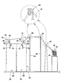
- the composite paper thread manufacturing apparatus according to the present invention is not limited to a form in which a Japanese paper roll 14, a slitter 16, a pair of delivery rollers 20, a covering machine 25, and the like are arranged over two floors in a building, for example. It may be arranged on one floor in the building. In another embodiment shown in FIG.
- At least one support column 94 is provided so that the Japanese paper tape 18 can be supplied to each covering unit 26 from above, and the direction changing jig 58 (at the tip of the support column 94) (for example, it is preferable to provide a snell wire) and run the Japanese paper tape 18 in a state of being lifted above the covering unit 26.
- Japanese paper tapes are assumed as a plurality of Japanese paper tapes, and a plurality of weight covering units are provided on the right side or the left side with respect to the feeding direction of the plurality of Japanese paper tapes.
- the number of Japanese paper tapes and the arrangement of the covering units of the plurality of weights described here are examples until they get tired, and are not particularly limited.
- the composite paper thread manufacturing apparatus 90 shown in FIG. 10 is preferably used.
- the composite paper thread manufacturing apparatus 90 slits a Japanese paper roll 14 in which a long Japanese paper sheet 12 is wound into a roll and a Japanese paper sheet 12 unwound from the Japanese paper roll 14 to narrow the width in the feed direction of the Japanese paper sheet 12.
- a pair of sending rollers 20 that sandwich (nip) the slitter 16 that forms the plurality of Japanese paper tapes 17 and each of the Japanese paper tapes 18 included in the plurality of Japanese paper tapes 17 formed by the slitter 16 and send them out at a constant speed.
- a distributor 21 that distributes a plurality of paper tapes 17 conveyed by a pair of delivery rollers 20 to each Japanese paper tape 18, a plurality of pairs of slip rollers (not shown), and a covering machine 25. To be equipped.
- the plurality of pairs of slip rollers are provided with a plurality of pairs of slip rollers so that a pair of slip rollers (not shown) correspond to each one paper tape 18 distributed from the plurality of paper tapes 17.
- Each pair of slip rollers sandwiches (nip) one distributed paper tape 18 and feeds it while slipping it.
- the covering machine 25 is provided with a plurality of weight covering units so that one weight covering unit 26 corresponds to each piece of paper tape 18 sent out from the pair of slip rollers.
- Each covering unit 26 is provided with at least one core yarn (first yarn) attached to one paper tape 18 sent out by a pair of slip rollers and falsely twisted while at least one auxiliary yarn (first thread). 2 threads) are wound and covered in a thread shape.
- the plurality of Japanese paper tapes 17 formed by slitting the Japanese paper sheet 12 with the slitter 16 are fed by a pair of feeding rollers 20 and then pressed by the pressing rollers 40 to change the feeding direction. Can be bent upwards.
- a plurality of weight covering units provided in the covering machine 25 are linearly arranged.
- the number of the plurality of Japanese paper tapes 17 is 120, 60 weight covering units are arranged in a row.
- the other 60 weight covering units are arranged in a row facing or back to back with the 60 weight covering unit. Therefore, a total of 120 weight covering units are arranged facing each other or back to back by 60 weights.
- a pair of slip rollers (not shown) are arranged for each of the 120 weight covering units 26.
- the plurality of Japanese paper tapes 17 whose feeding direction is bent upward by the pressing roller 40 pass above the covering unit of the plurality of weights, and are provided on the respective thread path members 22 in the distributor 21. Through the holes (plurality of guide paths, not shown), only one Japanese paper tape 18 is passed through each hole (one guide path). Therefore, each of the paper tapes 18 is distributed so as to run while maintaining a distance of one paper tape 18 so that the paper tapes 18 do not interfere with each other.
- two each distributed by the thread path member 22 are bent downward in the feed direction via a plurality of direction changing jigs (for example, snell wire, not shown), and bent downward. It is sent to a two-weight covering unit included in a plurality of weight covering units arranged in two rows through a pair of slip rollers (not shown) arranged in the above.
- Each covering unit 26 has already been described with reference to FIG.
- the working environment can be completed on one floor by arranging the Japanese paper roll 14, the slitter 16, the pair of sending rollers 20, the covering machine 25, etc. on one floor in the building. Is possible. Therefore, the workability of the composite paper yarn manufacturing apparatus 90 is improved as compared with the case where the composite paper yarns are arranged on the two floors.
- each covering is made by the composite paper yarn manufacturing apparatus (10, 90). It is preferable that the unit 26 is provided with a cutting detection device (not shown) that detects the cutting of the Japanese paper tape 18.
- the location where the disconnection detection device is provided is arbitrary, and is not limited to one location, and may be provided at a plurality of locations. It is also preferable from the viewpoint that when the cutting detection device detects the cutting of the Japanese paper tape 18, the covering unit 26 corresponding to the Japanese paper tape 18 can be selectively stopped.
- the cut detection device may be a known one, and a so-called non-contact type such as an optical type or a capacitance type is preferable.
- Each covering unit 26 may be provided with a cutting detection device capable of detecting the cutting of the auxiliary thread 70 or the core thread 72.
- a cutting detection device capable of detecting the cutting of the auxiliary thread 70 or the core thread 72.
- the cutting Japanese paper tape discharging device 116 for removing the cut Japanese paper tape is arbitrary. It is preferably provided at a location.
- the Japanese paper sheet 12 may have holes unexpectedly. In this case, if the Japanese paper sheet 12 is slit by the slitter 16 to form a plurality of narrow Japanese paper tapes 17, at least one Japanese paper tape is likely to be cut at the perforated portion. Therefore, it is preferable to remove the cut Japanese paper tape by suction with the paper dust suction device 34.
- the cutting Japanese paper tape discharging device 116 is preferably of a suction type in which a suction port is provided in the vicinity where a plurality of Japanese paper tapes 17 are fed by a pair of feeding rollers 20.
- the production of the composite paper thread can be continued as it is.
- the cut Japanese paper tape is cut by a suction device or the like. It is preferable that the tape is removed by suction.
- the composite paper yarn according to the present invention is formed by forming a fiber bundle in which one paper tape and at least one core yarn (first yarn) attached to the one paper tape are falsely twisted into an auxiliary yarn. It is a composite paper thread in which (second thread) is covered. From the viewpoint of increasing the breaking elongation of the composite paper yarn and increasing the breaking strength of the composite paper yarn, the composite paper yarn formed when the composite paper yarn is cut to a predetermined length in the longitudinal direction thereof.
- the length of one paper tape contained in the section of the composite paper thread is, for example, 1.05 times or more and 1.35 times or less, preferably 1.05 times or more and 1.35 times or less, as compared with the length of the first thread contained in the section of the composite paper thread.
- the magnification of the length mentioned here is the feed rate of the delivery roller 77 shown in FIG. 6 or 7, and the feed rate of the delivery roller 77 shown in FIG. 6 or FIG. It can be arbitrarily adjusted by changing the ratio of the pair of delivery rollers 20 shown to the feed rate. That is, if the feed rate of the pair of delivery rollers 20 is made faster than the feed rate of the delivery roller 77, the magnification of the length mentioned here can be increased.
- the composite paper thread according to the present invention is configured to avoid a situation in which only the paper tape portion is cut when strongly pulled.
- various clothes and the like are manufactured using the composite paper thread according to the present invention, it is possible to avoid a situation in which only the paper tape portion of the composite paper thread is cut and the cut paper tape portion appears on the surface of the clothing or the like. , The possibility of producing defective products can be reduced as compared with the case of producing clothing or the like using conventional composite paper threads.
- the composite paper yarn according to the present invention can be easily manufactured by using, for example, the composite paper yarn manufacturing apparatus 10 shown in FIG. 1 or the composite paper yarn manufacturing apparatus 90 shown in FIG. Therefore, the composite paper yarn according to the present invention is not limited in what kind of device is used for manufacturing, but it is preferably manufactured by using the composite paper yarn manufacturing device according to the present invention.
- the first long fiber in the composite paper yarn according to the present invention is appropriately selected depending on the use of the final product in which the composite paper yarn is used, and is, for example, a fineness of 20 denier (22.2 dtex) or more and 30 denier (30 denier). 33.3 dtex) or less polyester filament yarn can be mentioned.
- the second long fiber in the composite paper yarn according to the present invention is also appropriately selected according to the application of the final product, for example, when the fineness is 20 denier (22.2 dtex) or more and 30 denier (33.3 dtex) or less.
- Some polyester filament yarns are mentioned.
- the material of the first long fiber or the material of the second long fiber may be, for example, nylon, rayon, or the like.
- a first spun yarn may be used instead of the first long fiber.
- a second spun yarn may be used instead of the second long fiber.
- Various woven fabrics or knitted fabrics can be manufactured using the composite paper yarn according to the present invention. These fabrics or knits are used for clothing (clothes, innerwear, lining, etc.), shoes, socks, sheets, curtains, towels, masks or gauze used for medical treatment, handkerchiefs, etc. , It can be widely used for interior goods such as wallpaper, or industrial materials.
Landscapes
- Engineering & Computer Science (AREA)
- Mechanical Engineering (AREA)
- Textile Engineering (AREA)
- Yarns And Mechanical Finishing Of Yarns Or Ropes (AREA)
- Paper (AREA)
Abstract
【課題】紙シートがスリットされ形成された紙テープをそのままカバーリングユニットに供給し複合紙糸に加工する際、紙テープに張力の急激な変化を与えない複合紙糸製造装置および複合紙糸製造方法を提供する。 【課題を解決するための手段】例えば、和紙ロール14と、和紙ロール14から繰り出された和紙シート12をスリットし複数本の和紙テープ17を形成するスリッター16と、複数本の和紙テープ17を1本の和紙テープごとに分配する分配器21と、分配された1本の和紙テープ18ごとにスリップさせつつ送り出す一対のスリップローラが複数設けられて成る複数対のスリップローラと、一対のスリップローラから送り出された1本の和紙テープ18に第1の糸条を添えて仮撚りし第2の糸条でカバーリングする1錘のカバーリングユニット26が複数錘設けられて成るカバーリング機25と、を備える複合紙糸製造装置10である。
Description
本発明は、長繊維、及びスパン糸からなる群より選ばれた1種以上の糸と、紙テープと、が組み合わされて成る糸(以下「複合紙糸」という。)、並びに、複合紙糸の製造装置、並びに、複合紙糸の製造方法に関する。
近年、紙の特性を活かすことのできる紙糸を用いた製品が、数多く提供されるようになってきた。紙糸は、シート状の紙を数mm程度の幅にスリットし、スリットにより形成された紙テープを撚って糸にしたものである。従来、工業的に紙糸を製造する場合は、シート状の紙をスリッターにより各種サイズの幅にスリットし、形成された複数本の紙テープに含まれる各々1本の紙テープをチーズ若しくはコーン等にワインディングして巻き取り、巻体を得ていた。従来の撚糸メーカーは、必要とする幅の紙テープが巻き取られた巻体を選択し、その紙テープをカバーリング機にセットし、その紙テープを合成繊維等からなる長繊維などと共に撚ったり又は紙テープに長繊維などをカバーリングしたりして、複合紙糸を製造していた。カバーリングとは、芯糸などに長繊維などをコイル状に巻き付けてカバーリング糸を製造する加工をいう。紙テープの外周に長繊維またはスパン糸などが巻き付けられたカバーリング糸は、複合紙糸の一種といえる。
糸を巻き取る場合、糸で既に巻き取られた部分の表面には、糸による凹凸ができる。糸で更に巻き取られる部分は、糸で既に巻き取られた部分同士の間に生じた凹部に嵌まり込む。このため、糸を巻き取る場合、糸の巻き崩れが生じることはほとんどない。一方、紙テープを巻き取る場合、紙テープは扁平なテープ状であり、紙テープで既に巻き取られた部分の表面に凹凸がほとんど生じず、この表面上で紙テープが滑りやすい。このため、チーズ若しくはコーンに紙テープをワインディングして巻き取るとき、または、巻き取られた紙テープの巻体を保管しているとき、または、複合紙糸を製造するために巻体から紙テープを巻き出すときに、紙テープの巻き崩れが生じることがある。特に、幅が約1mmから約2mmという細幅の紙テープでは、巻き崩れが生じやすいだけでなく、細幅の紙テープの破断伸度が小さいため、巻き取るときにほんの少しの微衝撃で紙テープが切れてしまう傾向にある。したがって、従来、細幅の紙テープでは、巻取りが安定せず、取り扱いが非常に困難で、巻き取ったり巻体から引き出したりするときに紙テープが切れやすいため、材料ロスが多く、品質が不安定で製造しにくかった。本明細書で破断伸度とは、ASTM-D-882又はJIS-C-2151に準じて、引張試験機を用いて試料を速度200mm/minで引っ張り、試料が破断したときの伸び(引張伸び)である。破断伸度は、L0を「試験前の試料長さ」とし、Lを「破断時の試料長さ」とするときに、「引張伸び(%)=100×(L-L0)/L0」との数式により算出される。
従来、紙テープを用いてカバーリング機で複合紙糸を製造する際、紙テープの切れが多く発生することが、複合紙糸の品質を不安定にして生産性が悪い原因になった。従来、複合紙糸を製造するには、紙テープの巻取り作業や、巻き取られた紙テープをチーズ若しくはコーンから引き出してカバーリング機に設けられた各々のカバーリングユニットに紙テープをセットする作業は、毎回手作業で行われていた。これらの手作業を要するため、従来の複合紙糸製造装置および複合紙糸製造方法では、人的ロスや時間的ロスが多く、複合紙糸のコストダウンが妨げられていた。
そこで、本願発明者は、紙シートをスリッターでスリットして形成された紙テープを、従来の様に一旦巻き取った後に複合紙糸の製造に供するのではなくて、形成された紙テープを直接的に複合紙糸に加工することを以前に考えた。しかし、スリッターで紙シートをスリットすると、1枚の紙シートから約100本から200本程度の紙テープが作られる。これらの紙テープを1本ずつ全て同時に複合紙糸に加工するには、スリットで形成された紙テープの本数と同じ数の約100錘から約200錘のカバーリングユニットが設けられたカバーリング機を準備するだけでなく、各々のカバーリングユニットのために設置スペースと作業スペースとを要する。また、紙シートをスリッターでスリットして複数本の紙テープを形成後、1錘のカバーリングユニットごとに1本の紙テープが供給されるように、複数本の紙テープに含まれる各々1本の紙テープごとに直接的に1錘のカバーリングユニットへ供給するためには、複数錘のカバーリングユニットを並べて配置した中央にスリッターを配置しても、各々1本の紙テープを少なくとも15m前後の距離にわたり搬送する必要が生じる。幅1mm程度から数mm程度の紙テープを空中で搬送させると、紙テープが自重により切れてしまうことがある。これらを考慮し、以前に本願発明者は種々実験等を繰り返した結果、特許文献1に記載された発明を創作した。
その後、本願発明者は、実用化に向けて試作機で更に実験を重ねる過程で、次の知見を得た。紙テープを用いた従来のカバーリング糸の製造方法では、1錘のカバーリングユニットごとに1本の紙テープが送り込まれる過程で、各々の紙テープにほんの僅かな微衝撃が発生していることが分かった。薄く、細く、しかも破断伸度が小さい紙テープは、この僅かな微衝撃により容易に切断されてしまう傾向にあるが、静的負荷に対してはある程度の破断強力があることが分かった。本明細書で破断強力とは、ASTM-D-882又はJIS-C-2151に準じて、引張試験機を用いて試料を速度200mm/minで引っ張り、試料が破断したときの引張荷重値である。例えば、目付け10g/mm2で幅1.2mmの和紙テープでは、平均破断強力が69.0gf(0.68N)で、平均破断伸度が1.25%であった。目付け12g/mm2で幅1.2mmの和紙テープでは、平均破断強力が94.5gf(0.93N)で、平均破断伸度が1.25%であった。目付け10g/mm2で幅1.5mmの和紙テープでは、平均破断強力が96.5gf(0.95N)で、平均破断伸度が1.88%であった。いずれも試料の長さは200mmであった。これらの和紙テープでは、張力を測定すると3gf(0.029N)から10g(0.098N)であったが、和紙テープの切れが頻発し、紙糸製造装置の稼働率が40%から60%と低かった。和紙テープの平均破断強力が約70gf(約0.69N)もあるにも関わらず、この和紙テープが3gfから10gfの張力で切れる原因は、和紙テープの平均破断伸度が小さいためであろうと本願発明者は考えた。そこで、本願発明者は、1本の和紙テープごとにその形成からカバーリングユニットに供給されるまでの過程を観察した結果、和紙テープはその送り方向に微衝撃を加えられると切れてしまうことを見出した。その微衝撃の発生原因を追究した結果、本願発明者は本発明を創作するに至った。
本発明の課題は、紙シートをスリッターでスリットして形成された複数本の紙テープに含まれる各々1本の紙テープをそのまま連続的にカバーリング機に供給して複合紙糸に加工するとき、各々1本の紙テープに送り方向の微衝撃、すなわち張力の急激な変化を与えない機構を備えた新規な複合紙糸製造装置および複合紙糸製造方法を提供することにある。
また、本願発明者は、かかる新規な複合紙糸製造装置および複合紙糸製造方法により得られた複合紙糸を引っ張って破断強力の測定試験をしたときに、複合紙糸の紙部分(和紙のみ)が切れにくいことを見出した。なお、従来の紙糸製造装置で製造された複合紙糸は、引っ張られると、合成繊維からなる長繊維の部分は切れないが、紙部分が切れてしまうことが多い。紙部分が切れた複合紙糸を用いて織布または編物にして製品化した場合、切れた紙部分がほどけて製品の表面に現れてしまうことがある。表面に現れなかったとしても、切れた紙部分で複合紙糸の外観が異なり、製品の外観にムラが生ずる。このようなことになると、商品価値が減損してしまう。従来の複合紙糸製造装置や複合紙糸製造方法では、複合紙糸で紙部分が切れやすい問題を解決できなかった。一方、本願発明者による新規な複合紙糸製造装置および複合紙糸製造方法で製造された複合紙糸は、張力がかかっても紙部分が切れにくいことが分かった。
上記した課題を解決するために、本発明に係る複合紙糸製造装置は、1本の紙テープを挟持し一定速度で送り出す一対の送出しローラと、前記一対の送出しローラの一定速度と比べて1.000倍を超える表面速度で回転させられる駆動ローラを備え、前記1本の紙テープを挟持し且つ前記駆動ローラを前記1本の紙テープに対してスリップさせつつ前記1本の紙テープを送り出す一対のスリップローラと、前記一対のスリップローラにより送り出された前記1本の紙テープに第1の糸条を添えて仮撚りする仮撚り機構を有し、並びに、前記仮撚り機構の加撚域または解撚域において前記1本の紙テープおよび前記1本の紙テープに添えられた前記第1の糸条に第2の糸条をカバーリングするカバーリング機構を有する1錘のカバーリングユニットが設けられたカバーリング機と、を備え、前記第1の糸条は、第1の長繊維、第1のスパン糸、および、前記第1の長繊維と前記第1のスパン糸とが組み合わされた複合糸からなる群より選ばれた少なくとも1本の糸であり、前記第2の糸条は、第2の長繊維、第2のスパン糸、および、前記第2の長繊維と前記第2のスパン糸とが組み合わされた複合糸からなる群より選ばれた少なくとも1本の糸である、複合紙糸製造装置である。
または、本発明に係る複合紙糸製造装置は、長尺の紙シートがロール状に巻き取られた紙ロールと、前記紙ロールから繰り出された前記紙シートをスリットして前記紙シートの送り方向に細幅の複数本の紙テープを形成させるスリッターと、前記スリッターにより形成された前記複数本の紙テープを挟持し一定速度で送り出す一対の送出しローラと、前記一対の送出しローラにより搬送されてきた前記複数本の紙テープから1本の紙テープのみを通過させるように設けられたガイド路を複数有しており、前記複数本の紙テープを前記1本の紙テープごとに分配する分配器と、前記一対の送出しローラの一定速度と比べて1.000倍を超える表面速度で回転させられる駆動ローラを備え、前記分配器により分配された前記1本の紙テープを挟持し且つ前記駆動ローラを前記1本の紙テープに対してスリップさせつつ前記1本の紙テープを送り出す一対のスリップローラが、前記複数本の紙テープから分配された前記1本の紙テープごとに前記一対のスリップローラが対応するように複数設けられて成る複数対のスリップローラと、前記一対のスリップローラにより送り出された前記1本の紙テープに第1の糸条を添えて仮撚りする仮撚り機構を有し、並びに、前記仮撚り機構の加撚域または解撚域で前記1本の紙テープおよび前記1本の紙テープに添えられた第1の糸条に第2の糸条をカバーリングするカバーリング機構を有する1錘のカバーリングユニットが、前記一対のスリップローラにより送り出された前記1本の紙テープごとに前記1錘のカバーリングユニットが対応するように複数錘設けられたカバーリング機と、を備え、前記第1の糸条は、第1の長繊維、第1のスパン糸、および、前記第1の長繊維と前記第1のスパン糸とが組み合わされた複合糸からなる群より選ばれた少なくとも1本の糸であり、前記第2の糸条は、第2の長繊維、第2のスパン糸、および、前記第2の長繊維と前記第2のスパン糸とが組み合わされた複合糸からなる群より選ばれた少なくとも1本の糸である、複合紙糸製造装置である。
本発明に係る複合紙糸製造装置では、前記一対の送出しローラの送り速度と比べて、前記一対のスリップローラにおける前記駆動ローラの表面速度が1.005倍以上かつ1.050倍以下であり得る。
本発明に係る複合紙糸製造装置では、前記少なくとも1本の第1の糸条の送り速度と比べて、前記少なくとも1本の第1の糸条を添えて仮撚りされる前記1本の紙テープの送り速度が1.05倍以上かつ1.35倍以下であり得る。
本発明に係る複合紙糸製造装置では、前記一対のスリップローラは前記駆動ローラと従動ローラとを備えて成り、前記駆動ローラ、及び前記従動ローラからなる群より選ばれた少なくとも1つのローラにはローラ表面に紙に対する平滑処理が施されているものであり得る。
本発明に係る複合紙糸製造装置では、前記一対のスリップローラにおいて前記駆動ローラと前記従動ローラとは上下方向に配設されており、前記駆動ローラは前記従動ローラの下方に配設されており、前記従動ローラは前記駆動ローラの上方に配設されているものであり得る。
本発明に係る複合紙糸製造装置では、前記一対のスリップローラにおいて、前記従動ローラは任意に重量の異なるローラに変更可能に配設されているものであり得る。
本発明に係る複合紙糸製造方法は、1本の紙テープを送り出す工程と、送り出された前記1本の紙テープをスリップさせつつ送り出す工程と、スリップさせつつ送り出された前記1本の紙テープに第1の糸条を添えて仮撚りする工程と、前記仮撚りする工程において加撚域または解撚域で前記1本の紙テープおよび前記第1の糸条に第2の糸条をカバーリングする工程と、を含み、前記第1の糸条は、第1の長繊維、第1のスパン糸、および、前記第1の長繊維と前記第1のスパン糸とが組み合わされた複合糸からなる群より選ばれた少なくとも1本の糸であり、前記第2の糸条は、第2の長繊維、第2のスパン糸、および、前記第2の長繊維と前記第2のスパン糸とが組み合わされた複合糸からなる群より選ばれた少なくとも1本の糸である、複合紙糸製造方法である。
または、本発明に係る複合紙糸製造方法は、ロール状に巻き取られた紙シートを準備する工程と、前記紙シートを長手方向に送り出す工程と、送り出された前記紙シートの送り方向に細幅の複数本の紙テープが形成されるように前記紙シートをスリットする工程と、形成された前記複数本の紙テープを分配器により1本の紙テープごとに分配する工程と、分配された前記1本の紙テープごとにスリップさせつつ送り出す工程と、スリップさせつつ送り出された前記1本の紙テープごとに第1の糸条を添えて仮撚りする工程と、前記仮撚りする工程において加撚域または解撚域で、前記1本の紙テープおよび前記第1の糸条ごとに、第2の糸条をカバーリングする工程と、を含み、前記第1の糸条は、第1の長繊維、第1のスパン糸、および、前記第1の長繊維と前記第1のスパン糸とが組み合わされた複合糸からなる群より選ばれた少なくとも1本の糸であり、前記第2の糸条は、第2の長繊維、第2のスパン糸、および、前記第2の長繊維と前記第2のスパン糸とが組み合わされた複合糸からなる群より選ばれた少なくとも1本の糸である、複合紙糸製造方法である。
本発明に係る複合紙糸は、本発明に係る複合紙糸製造装置により製造された複合紙糸であり得る。
または、本発明に係る複合紙糸は、本発明に係る複合紙糸製造装置により製造された複合紙糸であって、前記複合紙糸が所定の長さで切り取られるときに、形成される前記複合紙糸の切片に含まれる前記第1の糸条の長さと比べて、前記複合紙糸の切片に含まれる前記1本の紙テープの長さが1.05倍以上かつ1.35倍以下である複合紙糸であり得る。
または、本発明に係る複合紙糸は、1本の紙テープと前記1本の紙テープに添えられる第1の糸条とが仮撚りされてなる繊維束に、第2の糸条がカバーリングされてなる複合紙糸であって、前記複合紙糸が所定の長さで切り取られるときに、形成される前記複合紙糸の切片に含まれる前記第1の糸条の長さと比べて、前記複合紙糸の切片に含まれる前記1本の紙テープの長さが1.05倍以上かつ1.35倍以下である複合紙糸であり得る。本発明に係る複合紙糸製造装置における前記分配器には、前記複数本の紙テープに含まれる1本の紙テープごとに1つの前記ガイド路が対応するように複数のガイド路が設けられているのが好ましい。本発明に係る複合紙糸製造装置、本発明に係る複合紙糸製造方法、及び本発明に係る複合紙糸において、前記第1の糸条は、少なくとも1本の前記第1の長繊維であるのが好ましく、1本の前記第1の長繊維であるのが更に好ましい。本発明に係る複合紙糸製造装置、本発明に係る複合紙糸製造方法、及び本発明に係る複合紙糸において、前記第2の糸条は、少なくとも1本の前記第2の長繊維であるのが好ましく、1本の前記第2の長繊維であるのが更に好ましい。
本発明に係る複合紙糸製造装置および複合紙糸製造方法の一例によれば、一対の送出しローラで1本の紙テープを一定速度で送り、その1本の紙テープの速度よりも速い表面速度で回転させられる一対のスリップローラで1本の紙テープをスリップさせつつ1つのカバーリングユニットに送るように構成している。一対のスリップローラの駆動ローラは、送出しローラの送り出し速度(一定速度)と比べて、1.000倍を超える表面速度、好ましくは1.005倍以上かつ1.050倍以下、より好ましくは1.008倍以上かつ1.025倍以下の表面速度で回転させられている。一対のスリップローラの送り速度は、駆動ローラの表面速度をいう。一対のスリップローラの送り速度が、送出しローラの送り出し速度と比べて、1.000倍を超える表面速度、好ましくは1.005倍を超える表面速度で回転させられると、1本の紙テープが切れることはほとんどなくなる。1本の紙テープは、一対のスリップローラの間を常にスリップした状態で送り出されており、1本の紙テープに急な送り方向の微衝撃(張力の急激な変化)が与えられることがほとんどない。このため、1本の紙テープを複合紙糸に加工する過程で、1本の紙テープが切れることはほとんどなく、1本の紙テープをカバーリング機に設けられた1錘のカバーリングユニットへ円滑に供給可能であり、複合紙糸が円滑に製造される。
本発明に係る複合紙糸製造装置および複合紙糸製造方法の他の例によれば、紙ロールから繰り出された紙シートがスリッターでスリットされ、複数本の紙テープが形成される。形成された複数本の紙テープは、一対の送出しローラにより一定速度で送り出される。送り出された複数本の紙テープは、分配器により1本の紙テープごとに分配される。1錘のカバーリングユニットごとに、分配された1本の紙テープが、一対のスリップローラを介して供給される。一対のスリップローラの駆動ローラは、送出しローラの送り出し速度(一定速度)と比べて、1.000倍を超える表面速度、好ましくは1.005倍以上かつ1.050倍以下、より好ましくは1.008倍以上かつ1.025倍以下の表面速度で回転させられている。一対のスリップローラの送り速度は、駆動ローラの表面速度をいう。一対のスリップローラの送り速度が送出しローラの送り出し速度と比べて1.000倍を超える表面速度、好ましくは1.005倍を超える表面速度で回転させられると、各々1本の紙テープが切れることはほとんどなくなる。各々1本の紙テープは、一対のスリップローラの間を常にスリップした状態で送り出されており、各々1本の紙テープに急な送り方向の微衝撃(張力の急激な変化)が与えられることがほとんどない。このため、複数本の紙テープに含まれる各々1本の紙テープを複合紙糸に加工する過程で、各々1本の紙テープが切れることはほとんどなく、カバーリング機に設けられた1錘のカバーリングユニットごとに1本の紙テープを円滑に供給可能であり、複合紙糸が円滑に製造される。
一対の送出しローラの送り速度が、第1の糸条の送り出し速度(デリベリローラの送り速度)と比べて、1.05倍以上かつ1.35倍以下、好ましくは1.10倍以上かつ1.20倍以下、より好ましくは1.14倍以上かつ1.17倍以下、更により好ましくは1.145倍以上かつ1.165倍以下の速い速度で回転させられると、紙テープの長さが第1の糸条の長さと比べて1.05倍以上かつ1.35倍以下となるようにオーバーフィードされやすい。このようにオーバーフィードさせて得られた複合紙糸では、第1の糸条が切れない程度に引っ張られたときに、紙部分(紙テープ)のみが切れてしまうことはほとんどなくなる。一対のスリップローラにより紙テープに常に一定の張力を付与して送り出すように構成しているため、得られた複合紙糸は均等に仮撚りされ、カバーリングされている。
以上に説明した理由により、従来と比べて、本発明に係る他の複合紙糸製造装置および複合紙糸製造方法では、紙シートを繰り出してから複合紙糸を得るまでの一連の作業を、紙ロールの紙シートが繰り出し尽くされてなくなるまで中断しなくて済みやすい。この複合紙糸製造装置において、複数本の紙テープのうち例えば数本の紙テープが切れても、複合紙糸製造装置を一旦停止させることなく、原則として紙ロールの紙シートが無くなるまで複合紙糸を製造し続けることが可能である。したがって、この一連の作業中、作業者が作業する余地はほとんどなくなるため、省人化を図ることができる。また、従来の様に紙シートがスリットされ形成された紙テープを一旦巻き取った後に複合紙糸の製造に供する製造装置および製造方法と比べて、本発明に係る複合紙糸製造装置および複合紙糸製造方法では、紙シートがスリットされ形成された複数本の紙テープをその形成後に連続して、1本の紙テープごとに分配して仮撚りしたりカバーリングしたりして複合紙糸に加工することにより、紙シートから複合紙糸を得るまでに要する時間を大幅に短縮し、複合紙糸の製造コストを大幅に削減可能である。
以上に説明した理由により、本発明に係る複合紙糸製造装置および複合紙糸製造方法では、一対のスリップローラにより紙テープを常に安定的に供給可能で、かつ、1錘のカバーリングユニットごとに1本の紙テープと第1の糸条と第2の糸条とを常に安定的に供給可能である。このため、紙テープと第1の糸条とが長手方向にわたり均等に仮撚りされやすく、長手方向にわたり第2の糸条で均等にカバーリングされやすい。したがって、製造された本発明に係る複合紙糸では、長手方向にわたり局部的なムラが生じにくい。
本発明にかかる複合紙糸は、所定の長さで切り取られるときに、形成される複合紙糸の切片に含まれる第1の糸条の長さと比べて、この複合紙糸の切片に含まれる1本の紙テープの長さが、好ましくは1.05倍以上かつ1.35倍以下、更に好ましくは1.10倍以上かつ1.20倍以下、更により好ましくは1.14倍以上かつ1.17倍以下、更にいっそうより好ましくは1.145倍以上かつ1.165倍以下になるように設定されているのが望ましい。このように製造された本発明に係る複合紙糸では、引っ張られたときに、第1の糸条が伸びる範囲内で紙テープがオーバーフィード量だけ真っ直ぐに伸ばされるため、紙テープのみが切れることはほとんどない。本発明に係る複合紙糸は、上述したように長手方向にわたり均等に撚られたものであるため、複合紙糸が局部的に短い距離で引っ張られても、紙テープのみの破断はほとんど発生しない。
以下、本発明に係る複合紙糸製造装置の一実施形態について、図面を参照しながら説明する。以下、本明細書では、紙として和紙を用いる場合の一実施形態を説明するが、洋紙などのその他の紙を用いる場合の実施形態を本発明から除外するものではない。
〔複合紙糸製造装置の概略構成〕
本発明の一実施形態に係る複合紙糸製造装置10は、図1に示すように、和紙ロール14と、スリッター16と、一対の送出しローラ20と、分配器21と、図1に示していない複数対のスリップローラ23(図6参照)と、カバーリング機25とを備える。和紙ロール14は、長尺の和紙シート12がロール状に巻き取られたものである。スリッター16は、和紙ロール14から繰り出された和紙シート12をスリットし、和紙シート12の送り方向に複数本の和紙テープ17を形成させるように配置されている。一対の送出しローラ20は、複数本の和紙テープ17を挟持(ニップ)して搬送するように配置されている。分配器21は、一対の送出しローラ20により送り出された複数本の和紙テープ17を、各々1本の和紙テープ18に分配するものである。図6に示す複数対のスリップローラ23は、図5に示す一対のスリップローラ24が複数設けられて成る。各々の一対のスリップローラ24は、分配された各々1本の和紙テープ18をスリップ可能に挟持(ニップ)しつつ搬送する。図1に示すカバーリング機25には、複数錘のカバーリングユニットが設けられている。各々のカバーリングユニット26は、図7に示すように、一対のスリップローラ24から送られてきた1本の和紙テープ18に第1の糸条72を添えて仮撚りする仮撚り機構81と、1本の和紙テープ18および第1の糸条72に第2の糸条70をカバーリングするカバーリング機構82とを有する。
本発明の一実施形態に係る複合紙糸製造装置10は、図1に示すように、和紙ロール14と、スリッター16と、一対の送出しローラ20と、分配器21と、図1に示していない複数対のスリップローラ23(図6参照)と、カバーリング機25とを備える。和紙ロール14は、長尺の和紙シート12がロール状に巻き取られたものである。スリッター16は、和紙ロール14から繰り出された和紙シート12をスリットし、和紙シート12の送り方向に複数本の和紙テープ17を形成させるように配置されている。一対の送出しローラ20は、複数本の和紙テープ17を挟持(ニップ)して搬送するように配置されている。分配器21は、一対の送出しローラ20により送り出された複数本の和紙テープ17を、各々1本の和紙テープ18に分配するものである。図6に示す複数対のスリップローラ23は、図5に示す一対のスリップローラ24が複数設けられて成る。各々の一対のスリップローラ24は、分配された各々1本の和紙テープ18をスリップ可能に挟持(ニップ)しつつ搬送する。図1に示すカバーリング機25には、複数錘のカバーリングユニットが設けられている。各々のカバーリングユニット26は、図7に示すように、一対のスリップローラ24から送られてきた1本の和紙テープ18に第1の糸条72を添えて仮撚りする仮撚り機構81と、1本の和紙テープ18および第1の糸条72に第2の糸条70をカバーリングするカバーリング機構82とを有する。
〔紙〕
本発明で用いられる紙は、細幅にスリットした後に撚って糸状に加工することができるものであれば、いわゆる洋紙、又は和紙などに特に限定されない。本発明で用いられる紙は、紙厚が薄く且つ細幅で破断強力が大きい紙である観点から、和紙であるのが好ましい。
本発明で用いられる紙は、細幅にスリットした後に撚って糸状に加工することができるものであれば、いわゆる洋紙、又は和紙などに特に限定されない。本発明で用いられる紙は、紙厚が薄く且つ細幅で破断強力が大きい紙である観点から、和紙であるのが好ましい。
和紙は、和紙に適した原料植物を叩解して得られる繊維を主成分とするスラリー状になった和紙原料を、漉いて作られる紙である。和紙に適した原料植物として、こうぞ、みつまた、雁皮、麻類、針葉樹、広葉樹、及び笹などからなる群より選ばれた1種または2種以上の植物が挙げられる。和紙の目付けは、製造しやすい観点から約8g/m2以上かつ約30g/m2以下の範囲内であると好ましいが、この範囲内を超えて目付けが大きいものや、この範囲を超えて目付けが小さいものも使用可能である。本発明で用いられる和紙は、20質量%以下であれば、上記した和紙原料以外に由来する原料繊維が含まれても良い。和紙に特有な吸湿性や強度を保つ観点から、本発明で用いられる和紙は、上記した和紙原料以外に由来する繊維の含有量を20質量%以下に抑えるのが好ましい。和紙に特有な吸湿性や強度を保つ観点から、本発明で用いられる和紙は、上記した和紙原料に由来する繊維の含有量が90質量%以上であるものが更に好ましい。
本発明で用いられる和紙シート12の幅や長さは、本発明の目的に反しない限り、特に限定されない。和紙シート12として例えば、幅120mm以上かつ500mm以下程度であり長さ10,000m以上かつ50,000m以下程度である長尺のシート状の和紙が好ましく挙げられる。和紙シート12は、長手方向に和紙原料の繊維の方向が可能な限り配向するように製造されるため、幅方向の引っ張り力に対しては比較的に破れやすいが、長手方向の引っ張り力に対しては相当に強くて破れにくく形成されている。このため、和紙シート12を長手方向にスリットし形成された複数本の和紙テープ17において、各々1本の和紙テープ18は、その幅が約0.8mm以上かつ約30mm以下でも、原料繊維の配向方向がランダムな紙(洋紙)製のテープと比べて、長手方向の引っ張り力に対して切れにくくなっている。
長尺の和紙シート12は、ローラ27にロール状に巻き取られて、和紙ロール14とされる。ローラ27は図示しない軸受に設置され、和紙ロール14から和紙シート12が円滑に繰り出されるようにされている。ローラ27又は軸受を図示しない駆動装置に連結させて、駆動装置の駆動力によりローラ27を回転させて、和紙ロール14から和紙シート12を円滑に繰り出し可能に構成しても良い。または、互いに平行な2本の回転ロールの上に和紙ロール14を載置し、2本の回転ロールを回転させることにより和紙ロール14から和紙シート12を送り出し可能に構成しても良い。または、図示しない駆動装置に連結された図1に示す一対の繰り出しローラ28により、和紙シート12を挟持(ニップ)し、和紙ロール14から和紙シート12を送り出し可能に構成するのが好ましい。
〔スリッター〕
スリッター16は、図2に示すように、複数の円盤状の回転刃29と、複数の円盤状の回転刃29の刃先が接触するか又は若干食い込むように設けられた平板状の対向部材33とを備える。和紙シート12がスリットされ形成された複数本の和紙テープ17において、例えば各々1本の和紙テープ18の幅が1.5mmであり和紙テープ18の本数が120本である場合、複数の回転刃30に含まれる各々の回転刃30は1.5mmピッチで121枚配置される。各々の回転刃30は、カミソリ状の薄い鋼板などによって外周が鋭利な刃を形成している。各々の回転刃30の厚みは限定されないが、例えば、隣り合う回転刃30と回転刃30との間隔が1.5mmピッチである場合、隣り合う回転刃30と回転刃30との間に1つのスペーサー32が介装されて調整される。複数の回転刃29は、図示しない駆動装置により回転させられ、複数の回転刃29と対向部材33との間を搬送される和紙シート12を円滑にスリットする。各々の回転刃30の直径は、特に限定されないが、例えば30mm以上かつ60mm以下程度が好ましい。対向部材33は、複数の回転刃29の刃先が少なくとも接触させられるため、刃先を摩耗させにくい樹脂素材製であるのが好ましい。対向部材33は、その全体が樹脂素材で構成されても良く、または、複数の回転刃29の刃先が接触する上部だけ樹脂素材で構成されても良い。対向部材33の形状は、図2に示すように平板状でも良いが、特に限定されない。例えば、対向部材の形状が円筒形または円柱形である場合、対向部材を複数の回転刃29と共に回転するように構成することも可能である。
スリッター16は、図2に示すように、複数の円盤状の回転刃29と、複数の円盤状の回転刃29の刃先が接触するか又は若干食い込むように設けられた平板状の対向部材33とを備える。和紙シート12がスリットされ形成された複数本の和紙テープ17において、例えば各々1本の和紙テープ18の幅が1.5mmであり和紙テープ18の本数が120本である場合、複数の回転刃30に含まれる各々の回転刃30は1.5mmピッチで121枚配置される。各々の回転刃30は、カミソリ状の薄い鋼板などによって外周が鋭利な刃を形成している。各々の回転刃30の厚みは限定されないが、例えば、隣り合う回転刃30と回転刃30との間隔が1.5mmピッチである場合、隣り合う回転刃30と回転刃30との間に1つのスペーサー32が介装されて調整される。複数の回転刃29は、図示しない駆動装置により回転させられ、複数の回転刃29と対向部材33との間を搬送される和紙シート12を円滑にスリットする。各々の回転刃30の直径は、特に限定されないが、例えば30mm以上かつ60mm以下程度が好ましい。対向部材33は、複数の回転刃29の刃先が少なくとも接触させられるため、刃先を摩耗させにくい樹脂素材製であるのが好ましい。対向部材33は、その全体が樹脂素材で構成されても良く、または、複数の回転刃29の刃先が接触する上部だけ樹脂素材で構成されても良い。対向部材33の形状は、図2に示すように平板状でも良いが、特に限定されない。例えば、対向部材の形状が円筒形または円柱形である場合、対向部材を複数の回転刃29と共に回転するように構成することも可能である。
和紙シート12がスリッター16でスリットされ形成された複数本の和紙テープ17において、各々1本の和紙テープ18の幅が約0.8mm以上かつ約30mm以下の範囲内になるように、回転刃30と回転刃30との間のピッチが設定される。複数の回転刃29の厚みと複数個のスペーサー31の厚みとの合計が、複数本の和紙テープ17の幅に相当する。このため、各々1本の和紙テープ18の幅を変更する場合には、複数のスペーサー31に含まれる各々のスペーサー32の厚みを変更する。例えば、1枚の和紙シート12から120本の和紙テープ17を得るためには、121枚の回転刃29と120個のスペーサー31とに相当する分、各々の回転刃30と各々のスペーサー32とを交互に配置することになる。各々のスペーサー32は、回転刃30と回転刃30との間のピッチに応じて適宜適切な幅を有するものに変更して良く、一定の幅を有するスペーサー32を使用しても良い。
和紙シート12を安定的にスリットする観点から、スリッター16で和紙シート12をスリットする際、和紙シート12の両サイド部分を、複数本の和紙テープ17に含まれない2つの耳部19として扱うのが好ましい。同様の観点から、2つの耳部19における個々の耳部の幅は、少なくとも3mm以上かつ6mm以下程度あるのが好ましい。和紙シート12の両サイド部分は、不要な2つの耳部19として回収され、新たな和紙の原料として再資源化されるのが好ましい。
和紙シート12がスリッター16でスリットされる間隔、つまり、複数本の和紙テープ17に含まれる各々1本の和紙テープ18の幅は、全て一定でも良いが、特に限定されない。例えば、1mm幅の和紙テープと、2mm幅の和紙テープとを同時に形成させることも可能であり、この場合、用いられた和紙テープの幅が異なる2種類の複合紙糸が同時に製造されることになる。
〔紙粉吸引装置〕
次に説明する問題を避ける観点から、スリッター16の近傍部に紙粉吸引装置34を設けるのが好ましい。スリッター16で和紙シート12をスリットするとき、細かい紙粉が相当量発生し、周辺のフレームその他の部材の表面に蓄積してくる。この紙粉を放置しておくと、蓄積した紙粉により和紙テープ18が切れたり、その他にも複合和紙糸製造装置でトラブルの原因になったりするおそれがある。紙粉吸引装置33は、後述する切断和紙テープ排出装置が吸引式である場合、兼用とすることも可能である。紙粉吸引装置34は、破断した和紙テープを排除する機能も有する。つまり、和紙シート12にピンホール等の孔があいている場合、和紙シート12がスリッター16でスリットされたときに、孔が形成されている箇所で和紙テープが破断してしまう。紙粉吸引装置34は、このような破断した和紙テープを吸引して排除する。
次に説明する問題を避ける観点から、スリッター16の近傍部に紙粉吸引装置34を設けるのが好ましい。スリッター16で和紙シート12をスリットするとき、細かい紙粉が相当量発生し、周辺のフレームその他の部材の表面に蓄積してくる。この紙粉を放置しておくと、蓄積した紙粉により和紙テープ18が切れたり、その他にも複合和紙糸製造装置でトラブルの原因になったりするおそれがある。紙粉吸引装置33は、後述する切断和紙テープ排出装置が吸引式である場合、兼用とすることも可能である。紙粉吸引装置34は、破断した和紙テープを排除する機能も有する。つまり、和紙シート12にピンホール等の孔があいている場合、和紙シート12がスリッター16でスリットされたときに、孔が形成されている箇所で和紙テープが破断してしまう。紙粉吸引装置34は、このような破断した和紙テープを吸引して排除する。
〔櫛歯状のセンサー〕
スリッター16により形成された複数本の和紙テープ17がその形成直後に送り出される辺りに、櫛歯状のセンサー35を設けるのが好ましい。櫛歯状のセンサー35は、複数本の和紙テープ17に含まれる各々1本の和紙テープ18同士の間に差し込まれ、及び複数本の和紙テープ18と耳部19との間に差し込まれる、複数のプレート36を備える。複数のプレート36に含まれる各々のプレート37は、厚さが0.1mm以上かつ0.5mm以下程度であるのが好ましく、1本の軸に回転自由に取り付けられている。複数のプレート36の側部には図示しない光センサーが配置されていて、複数のプレート36のうち少なくとも1枚のプレート37が回転させられて光を遮ったとき、光センサーが作動するように構成されている。和紙シート12をスリッター16でスリットして複数本の和紙テープ17を形成させているが、隣り合う和紙テープ18同士が完全に切り離されていなかったとしても、複数のプレート36により隣り合う和紙テープ18同士を完全に切り離すことができる。いずれかの回転刃30が摩耗した等の原因で、和紙シート12から複数本の和紙テープ17へ完全にスリットできていない箇所が生じたとき、スリットできていない箇所が複数のプレート36に含まれるいずれかのプレート37に当たり、いずれか当たったプレート37が回転させられることにより櫛歯状のセンサー35が作動し、複合和紙糸製造装置が停止させられる。このように停止させられた場合は、スリッター16を新品に交換するか、または、複数の回転刃29の刃先と対向部材33との間隔を調整するかした後、複合和紙糸製造装置を再稼働させるのが好ましい。
スリッター16により形成された複数本の和紙テープ17がその形成直後に送り出される辺りに、櫛歯状のセンサー35を設けるのが好ましい。櫛歯状のセンサー35は、複数本の和紙テープ17に含まれる各々1本の和紙テープ18同士の間に差し込まれ、及び複数本の和紙テープ18と耳部19との間に差し込まれる、複数のプレート36を備える。複数のプレート36に含まれる各々のプレート37は、厚さが0.1mm以上かつ0.5mm以下程度であるのが好ましく、1本の軸に回転自由に取り付けられている。複数のプレート36の側部には図示しない光センサーが配置されていて、複数のプレート36のうち少なくとも1枚のプレート37が回転させられて光を遮ったとき、光センサーが作動するように構成されている。和紙シート12をスリッター16でスリットして複数本の和紙テープ17を形成させているが、隣り合う和紙テープ18同士が完全に切り離されていなかったとしても、複数のプレート36により隣り合う和紙テープ18同士を完全に切り離すことができる。いずれかの回転刃30が摩耗した等の原因で、和紙シート12から複数本の和紙テープ17へ完全にスリットできていない箇所が生じたとき、スリットできていない箇所が複数のプレート36に含まれるいずれかのプレート37に当たり、いずれか当たったプレート37が回転させられることにより櫛歯状のセンサー35が作動し、複合和紙糸製造装置が停止させられる。このように停止させられた場合は、スリッター16を新品に交換するか、または、複数の回転刃29の刃先と対向部材33との間隔を調整するかした後、複合和紙糸製造装置を再稼働させるのが好ましい。
〔送出しローラ〕
図1に示すように、和紙ロール14から繰り出される和紙シート12が、スリッター16でスリットされる。スリットにより形成された複数本の和紙テープ17に含まれる各々1本の和紙テープ18が、一対の送出しローラ20により一定速度で送られる。つまり、和紙シート12は、一対の送出しローラ20により和紙ロール14から引き出され、和紙ロール14から送出しローラ20へ至る過程でスリッター16によりスリットされる。スリットにより形成された複数本の和紙テープ17と2つの耳部19(図2参照)とは、一対の送出しローラ20に挟持(ニップ)されて送り出される。図3に示すように、一対の送出しローラ20は、減速機付きの駆動装置39により駆動させられるように構成されている。複数本の和紙テープ17に含まれる各々1本の和紙テープ18を確実に搬送する観点から、一対の送出しローラ20における各々のローラ38のローラの表面は、ゴム又は樹脂などで形成されているのが好ましい。同様の観点から、一対の送出しローラ20では、各々のローラ38が互いに密着し得るようにバネなどで押圧されているのが好ましい。一対の送出しローラ20から送り出された2つの耳部19(図2参照)は、回収され除去される。
図1に示すように、和紙ロール14から繰り出される和紙シート12が、スリッター16でスリットされる。スリットにより形成された複数本の和紙テープ17に含まれる各々1本の和紙テープ18が、一対の送出しローラ20により一定速度で送られる。つまり、和紙シート12は、一対の送出しローラ20により和紙ロール14から引き出され、和紙ロール14から送出しローラ20へ至る過程でスリッター16によりスリットされる。スリットにより形成された複数本の和紙テープ17と2つの耳部19(図2参照)とは、一対の送出しローラ20に挟持(ニップ)されて送り出される。図3に示すように、一対の送出しローラ20は、減速機付きの駆動装置39により駆動させられるように構成されている。複数本の和紙テープ17に含まれる各々1本の和紙テープ18を確実に搬送する観点から、一対の送出しローラ20における各々のローラ38のローラの表面は、ゴム又は樹脂などで形成されているのが好ましい。同様の観点から、一対の送出しローラ20では、各々のローラ38が互いに密着し得るようにバネなどで押圧されているのが好ましい。一対の送出しローラ20から送り出された2つの耳部19(図2参照)は、回収され除去される。
〔分配器〕
複数本の和紙テープ17に含まれる各々1本の和紙テープを後に1本ずつ分配するのを容易にする観点から、一対の送出しローラ20から送り出された複数本の和紙テープ17で形成された束を、例えば図1(b)に示すように分割するのが好ましい。例えば、和紙シート12から120本の和紙テープ17が形成された場合、この120本を40本ずつの3つの束に分割するのが好ましい。分割の一例として、120本の和紙テープ17で形成された束を第1の押さえローラ40で押さえてこの120本から40本の和紙テープ17を取り出し、残り80本の和紙テープ17で形成された束を送って第2の押さえローラ41で押さえて40本の和紙テープ17を取り出し、残り40本の和紙テープ17で形成された束を送って第3の押さえローラ42で押さえてこの40本を取り出すのが良い。分割の他の例として、120本の和紙テープ17を30本ずつの束に4分割しても良い。複数本の和紙テープ17をどの様に分割するのが良いか、特に限定されない。押さえローラ(40,41,42)は各々、複数本の和紙テープ17で形成された束の上面を押さえて所定本数の束を取り出すためのものであり、複数本の和紙テープ17に負荷を与えないように回転自由に構成されている。複数本の和紙テープ17で形成された束の下面側には、押さえローラ(40,41,42)各々と対向するローラを更に設けても良いし又は設けなくても良い。押さえローラ(40,41,42)各々に代えて、複数本の和紙テープ17で形成された束を分割可能な櫛状の部材を設けても良い。
複数本の和紙テープ17に含まれる各々1本の和紙テープを後に1本ずつ分配するのを容易にする観点から、一対の送出しローラ20から送り出された複数本の和紙テープ17で形成された束を、例えば図1(b)に示すように分割するのが好ましい。例えば、和紙シート12から120本の和紙テープ17が形成された場合、この120本を40本ずつの3つの束に分割するのが好ましい。分割の一例として、120本の和紙テープ17で形成された束を第1の押さえローラ40で押さえてこの120本から40本の和紙テープ17を取り出し、残り80本の和紙テープ17で形成された束を送って第2の押さえローラ41で押さえて40本の和紙テープ17を取り出し、残り40本の和紙テープ17で形成された束を送って第3の押さえローラ42で押さえてこの40本を取り出すのが良い。分割の他の例として、120本の和紙テープ17を30本ずつの束に4分割しても良い。複数本の和紙テープ17をどの様に分割するのが良いか、特に限定されない。押さえローラ(40,41,42)は各々、複数本の和紙テープ17で形成された束の上面を押さえて所定本数の束を取り出すためのものであり、複数本の和紙テープ17に負荷を与えないように回転自由に構成されている。複数本の和紙テープ17で形成された束の下面側には、押さえローラ(40,41,42)各々と対向するローラを更に設けても良いし又は設けなくても良い。押さえローラ(40,41,42)各々に代えて、複数本の和紙テープ17で形成された束を分割可能な櫛状の部材を設けても良い。
例えば、分配器21は複数の糸道部材を有し、複数本の和紙テープ17で形成された束から取り出された40本の和紙テープ17は、1つの糸道部材22により1本ずつに分配される。このためには、例えば、図4に示す各々の糸道部材22では、プレート44に複数個の孔(複数のガイド路)46が形成されている。例えば、糸道部材22のプレート44には、少なくとも40個の孔(複数のガイド路)46が形成されている。各々の孔(各々のガイド路)47同士の水平方向の配置は、各々1本の和紙テープ18の幅Wに応じて、その幅Wだけずらせている。このため、複数本の和紙テープ17に含まれる1本の和紙テープ18ごとに、1個の孔(1つのガイド路)47に水平方向に折れ曲がることなく真っ直ぐに挿通される。各々の孔(各々のガイド路)47同士の上下方向の配置は限定されないが、隣接する各々1本の和紙テープ18同士が接触することがないように配置される。各々の孔(各々のガイド路)47の内周面には、和紙テープ18との摩擦抵抗が少なくて和紙テープ18との接触により摩耗しにくい材質の保護部材が埋め込まれているのが好ましい。保護部材の材質として例えば、セラミックス、又は硬質樹脂などが好ましく挙げられる。
分配器21における糸道部材22に設けられた各々の孔(各々のガイド路)47には、1本の和紙テープ18が挿入される。例えば、40本の和紙テープ17で形成された束は、各々1本の和紙テープ18の並びの順に対応するように、糸道部材22に設けられた各々の孔(各々のガイド路)47に下から上の順に挿通される。複数本の和紙テープ17で形成された束は平面的であるが、この束に含まれる各々1本の和紙テープ18を、糸道部材22に設けられた各々の孔(各々のガイド路)47により上下左右のいずれかの方向へ分配することにより、和紙テープ18同士が絡み合ったり接触したりして破断することを回避できる。このように分配器21により、複数本の和紙テープ17は1本の和紙テープ18ごとに分配される。分配された1本の和紙テープ18ごとに、図5(a)と図5(b)とに示す一対のスリップローラ24を介して、1錘のカバーリングユニット26に送られることとなる。
分配器21では、複数本の和紙テープ17に含まれる1本の和紙テープ18ごとに1個の孔(1つのガイド路)47が対応するように、複数個の孔(複数のガイド路)46が設けられているのが好ましい。分配器21は、図1に例示するように糸道部材22を複数有して成るものに限らず、1つの糸道部材22を有して成るものでも良い。分配器21は、図4に示すようにプレート44に複数個の孔(複数のガイド路)46が設けられた糸道部材22を有して成るものに限らず、例えば複数個の孔(複数のガイド路)46の代わりに、プレート44に複数の方向変換治具が配置されたものでも良く又はプレート44に櫛状の歯が設けられたものでも良い。各々の方向変換治具は、本発明の目的に反しない限り特に限定されないが、一例としてスネルワイヤが挙げられる。
〔スリップローラ〕
図6に示す複数対のスリップローラ23に含まれる各々の一対のスリップローラ24は、図1や図2で示した複数本の和紙テープ17に含まれる和紙テープ18の本数に対応するように同じ数の対が準備される。図5に示すように、各々の一対のスリップローラ24は、上下方向に配設された駆動ローラ48と従動ローラ50とを備えて成る。各々の一対のスリップローラ24において、駆動ローラ48は、従動ローラ50の下方に配設されており、従動ローラ50は、駆動ローラ48の上方において、駆動ローラ48のローラ表面に接触して従動させられるように配設されている。駆動ローラ48は、図示しない駆動装置により駆動させられる。例えば、1列に並べて配置された複数錘のカバーリングユニットに対応するように、複数対のスリップローラが1列に並べて配置されても良い。複数対のスリップローラに含まれる各々の駆動ローラ48がまとめて一つの駆動装置により駆動させられるように、1本の駆動軸52を設けるのが好ましい。駆動ローラ48は、取付部材54に配設された図示しない軸受に駆動軸52を取り付け、その駆動軸52によって回転駆動させられる。従動ローラ50は、取付部材54に形成されたU字状の軸受56に、上下方向に移動可能に取り付けられる。従動ローラ50の軸51は、軸受56のU字状の底に当接しないように構成されている。このため、従動ローラ50の軸51は軸受56に上下方向に支持されることはなく、従動ローラ50は駆動ローラ48に従動させられる。
図6に示す複数対のスリップローラ23に含まれる各々の一対のスリップローラ24は、図1や図2で示した複数本の和紙テープ17に含まれる和紙テープ18の本数に対応するように同じ数の対が準備される。図5に示すように、各々の一対のスリップローラ24は、上下方向に配設された駆動ローラ48と従動ローラ50とを備えて成る。各々の一対のスリップローラ24において、駆動ローラ48は、従動ローラ50の下方に配設されており、従動ローラ50は、駆動ローラ48の上方において、駆動ローラ48のローラ表面に接触して従動させられるように配設されている。駆動ローラ48は、図示しない駆動装置により駆動させられる。例えば、1列に並べて配置された複数錘のカバーリングユニットに対応するように、複数対のスリップローラが1列に並べて配置されても良い。複数対のスリップローラに含まれる各々の駆動ローラ48がまとめて一つの駆動装置により駆動させられるように、1本の駆動軸52を設けるのが好ましい。駆動ローラ48は、取付部材54に配設された図示しない軸受に駆動軸52を取り付け、その駆動軸52によって回転駆動させられる。従動ローラ50は、取付部材54に形成されたU字状の軸受56に、上下方向に移動可能に取り付けられる。従動ローラ50の軸51は、軸受56のU字状の底に当接しないように構成されている。このため、従動ローラ50の軸51は軸受56に上下方向に支持されることはなく、従動ローラ50は駆動ローラ48に従動させられる。
各々1本の和紙テープ18を効率良くスリップさせやすい観点から、駆動ローラ48、及び従動ローラ50からなる群より選ばれた1種以上のローラは、ローラ表面に紙に対する平滑処理が施されたローラ、つまり、ローラ表面上で紙との摩擦を減らしてローラ表面上で紙を滑りやすくする処理が施されたローラであるのが好ましい。同様の観点から例えば、駆動ローラ48、及び従動ローラ50からなる群より選ばれた1種以上のローラが、梨地加工を施されたローラであるのが更に好ましい。または、同様の観点から、駆動ローラ48はローラ表面をクロムメッキされており、従動ローラ50はローラ表面を梨地加工されているのが好ましい。従動ローラ50の重量は、駆動ローラ48と従動ローラ50との間に挟持(ニップ)される1本の和紙テープ18が、駆動ローラ48の回転に抗してスリップしても和紙テープ18が破断しない程度の押圧力とされる。1本の和紙テープ18は駆動ローラ48と従動ローラ50とに挟まれた状態で駆動ローラ48に対してスリップさせられる。分配器21における糸道部材22と一対のスリップローラ24との間にある1本の和紙テープ18の張力を予め測定し、張力が高い場合は従動ローラ50の重量が低いものを選定し、逆に張力が低い場合は従動ローラ50の重量が重いものが選定される。重量の異なる従動ローラ50に適宜取り換えられるように、U字状の軸受56が用いられる。
図5に示す各々の一対のスリップローラ24の駆動ローラ48は、図1に示す一対の送出しローラ20での複数本の紙テープ17に含まれる各々1本の和紙テープ18の送り速度と比べて、1.000倍を超える速度、好ましくは1.005倍以上かつ1.050倍以下、より好ましくは1.005倍以上かつ1.025倍以下、更により好ましくは1.010倍以上かつ1.020倍以下の表面速度で図5に示す1本の和紙テープ18を送るように回転させられる。ここで挙げた1.005倍以上かつ1.050倍以下という数値範囲は、理論的な数値範囲ではなくて、本願発明者が実験を繰り返して以下に説明する好ましい観察結果を得られた数値範囲である。観察結果として、図1に示す送出しローラ20の送り速度と比べて、図5に示す各々の一対のスリップローラ24の駆動ローラ48の表面速度を速くすると、駆動ローラ48は各々1本の和紙テープ18に対して常にスリップさせられていて、一対のスリップローラ24に対して上流側(一対の送出しローラ20側)にある各々1本の和紙テープ18は常に弛むことがない。観察結果として、駆動ローラ48は各々1本の和紙テープ18に対して常時スリップした状態であるため、各々1本の和紙テープ18に送り方向の急激な張力の変化を与えることはなく、各々1本の和紙テープ18が切れることはなかった。各々1本の和紙テープ18では、後述する仮撚りの際のバルーニングにより張力の変動が生じると考えられるが、一対のスリップローラ24に備えられた駆動ローラ48と従動ローラ50との間をスリップすることにより張力の変動が吸収されるため、各々1本の和紙テープ18が実質的に切れなくなるものと観察結果から考えられる。一対のスリップローラ24は、1本の和紙テープ18ごとに配設されている。図6に示すように、一対のスリップローラ24は、1錘のカバーリングユニット26ごとに、1本の和紙テープ18を供給するように配設されている。
一対のスリップローラ24のうちの駆動ローラ48は、1本の和紙テープ18に対してほぼ常時スリップさせられるように構成されているのが好ましい。このスリップは、連続的に行われても良いし、又は間欠的に行われても良い。すなわち、駆動ローラ48の表面速度と送出しローラ20の送り速度との比が和紙テープ18の破断伸度以下に設定されている場合、1本の和紙テープ18は駆動ローラ48の表面で引き延ばされ、スリップしない状態で駆動ローラ48が回転させられ、1本の和紙テープ18は送り出される。1本の和紙テープ18に過度の張力がかかったときに、1本の和紙テープ18と駆動ローラ48の表面とでスリップが生じる。このようにスリップが間欠的に行われる場合が想定されるが、このような場合も、本願発明に含まれるものである。
〔支持ローラ〕
図1に示すように、各々1本の和紙テープ18は、和紙シート12がスリッター16でスリットされて複数本の和紙テープ17が形成された後、カバーリングユニット26まで搬送される。各々1本の和紙テープ18は、形成されてからカバーリングユニット26に搬送されるまでの間、適宜、少なくとも1つの支持ローラ57で支持されるのが好ましい。各々1本の和紙テープ18に負荷される抵抗を小さく抑える観点から、少なくとも1つの支持ローラ57の本数は、少なく抑えるのが好ましい。
図1に示すように、各々1本の和紙テープ18は、和紙シート12がスリッター16でスリットされて複数本の和紙テープ17が形成された後、カバーリングユニット26まで搬送される。各々1本の和紙テープ18は、形成されてからカバーリングユニット26に搬送されるまでの間、適宜、少なくとも1つの支持ローラ57で支持されるのが好ましい。各々1本の和紙テープ18に負荷される抵抗を小さく抑える観点から、少なくとも1つの支持ローラ57の本数は、少なく抑えるのが好ましい。
〔カバーリング機〕
例えば図6に示すように、一対のスリップローラ24から送り出された1本の和紙テープ18ごとに1錘のカバーリングユニット26が対応するように、カバーリング機25には複数錘のカバーリングユニットが設けられる。省コスト化と省スペース化とを図る観点から、カバーリング機25に設けられた複数錘のカバーリングユニットの配置は、図1と図6とで示すように、複数錘のカバーリングユニットの半数を第1ユニット群59に分類して残る半数を第2ユニット群60に分類した上で、各々1本の和紙テープ18の送り方向に沿って、第1ユニット群59と第2ユニット群60とが向かい合わせか又は背中合わせになるように並べるのが好ましい。このように並べると、第1ユニット群59に含まれる各々のカバーリングユニット26に対応する複数対のスリップローラ24に含まれる全ての駆動ローラは、一列に並ぶため、1本の駆動軸52でまとめて駆動可能である。同様に、第2ユニット群60に含まれる各々のカバーリングユニット26に対応する複数対のスリップローラ24に含まれる全ての駆動ローラは、他の1本の駆動軸52でまとめて駆動可能である。これら2本の駆動軸を、ギヤ、ベルト、又はチェーン等で連結し、一つの駆動装置で駆動させれば、省コスト化を図れる。さらに、各々の一対のスリップローラ24から送り出された1本の和紙テープ18ごとに対応して配置された各々のカバーリングユニット26を駆動させるための後述する走行ベルト65(図7,図8参照)も、1本で構成することができ、更なるコストダウンを図ることができる。なお、分配器21に設けられた複数個の孔46により1本ずつに分配された和紙テープ18が、任意のカバーリングユニット26に対応して配置された一対のスリップローラ24に導かれるように、方向変換治具58を配置するのが好ましい。方向変換治具58として例えばスネルワイヤが挙げられる。
例えば図6に示すように、一対のスリップローラ24から送り出された1本の和紙テープ18ごとに1錘のカバーリングユニット26が対応するように、カバーリング機25には複数錘のカバーリングユニットが設けられる。省コスト化と省スペース化とを図る観点から、カバーリング機25に設けられた複数錘のカバーリングユニットの配置は、図1と図6とで示すように、複数錘のカバーリングユニットの半数を第1ユニット群59に分類して残る半数を第2ユニット群60に分類した上で、各々1本の和紙テープ18の送り方向に沿って、第1ユニット群59と第2ユニット群60とが向かい合わせか又は背中合わせになるように並べるのが好ましい。このように並べると、第1ユニット群59に含まれる各々のカバーリングユニット26に対応する複数対のスリップローラ24に含まれる全ての駆動ローラは、一列に並ぶため、1本の駆動軸52でまとめて駆動可能である。同様に、第2ユニット群60に含まれる各々のカバーリングユニット26に対応する複数対のスリップローラ24に含まれる全ての駆動ローラは、他の1本の駆動軸52でまとめて駆動可能である。これら2本の駆動軸を、ギヤ、ベルト、又はチェーン等で連結し、一つの駆動装置で駆動させれば、省コスト化を図れる。さらに、各々の一対のスリップローラ24から送り出された1本の和紙テープ18ごとに対応して配置された各々のカバーリングユニット26を駆動させるための後述する走行ベルト65(図7,図8参照)も、1本で構成することができ、更なるコストダウンを図ることができる。なお、分配器21に設けられた複数個の孔46により1本ずつに分配された和紙テープ18が、任意のカバーリングユニット26に対応して配置された一対のスリップローラ24に導かれるように、方向変換治具58を配置するのが好ましい。方向変換治具58として例えばスネルワイヤが挙げられる。
図7に示すように、各々のカバーリングユニット26では、1本の紙テープ18と、少なくとも1本の芯糸(第1の糸条)72と、少なくとも1本の副糸(第2の糸条)70とから、カバーリング糸(複合紙糸)80が製造される。少なくとも1本の芯糸(第1の糸条)72は、第1の長繊維、第1のスパン糸、および、第1の長繊維と第1のスパン糸とが組み合わされた複合糸からなる群より選ばれた少なくとも1本の糸である。少なくとも1本の副糸(第2の糸条)70は、第2の長繊維、第2のスパン糸、および、第2の長繊維と第2のスパン糸とが組み合わされた複合糸からなる群より選ばれた少なくとも1本の糸である。第1の長繊維は、カバーリング糸(複合紙糸)80が用いられる最終製品の用途に応じて適宜選択され、例えば繊度が20デニール(22.2dtex)以上かつ30デニール(33.3dtex)以下であるポリエステルフィラメント糸が挙げられる。同様の理由から第2の長繊維も、最終製品の用途に応じて適宜選択され、例えば繊度が20デニール(22.2dtex)以上かつ30デニール(33.3dtex)以下であるポリエステルフィラメント糸が挙げられる。第1の長繊維の素材または第2の長繊維の素材は、例えば、ナイロン、又はレーヨン等でも良い。第1のスパン糸または第2のスパン糸として例えば、天然繊維または合成繊維を用いて紡績した糸が挙げられる。複合糸として例えば、長繊維とスパン糸との交撚糸、または、長繊維の外周にスパン糸が巻き付けられた糸などが挙げられる。伸びやすい糸である観点とカバーリング糸(複合紙糸)80を製造しやすい観点とから、少なくとも1本の芯糸(第1の糸条)72は、少なくとも1本の第1の長繊維であるのが好ましく、1本の第1の長繊維であるのが更に好ましい。同様の観点から、少なくとも1本の副糸(第2の糸条)70は、少なくとも1本の第2の長繊維であるのが好ましく、1本の第2の長繊維であるのが更に好ましい。
各々のカバーリングユニット26は、フレーム63に固定された軸受64に支持され、外周の一部が走行ベルト65に接触させられることにより回転させられる回転筒状体66と、この回転筒状体66に外装される中空ボビン68に少なくとも1本の副糸(第2の糸条)70が巻き付けられた巻体71と、を有するカバーリング機構82を備える。少なくとも1本の副糸70は、1本でも良いし、又は複数本でも良い。少なくとも1本の副糸70は、複数本からなる場合に同種または異種のいずれでも良く、予め同種または異種の複数本の副糸を束ねて中空ボビン68に巻いておくのが好ましい。回転筒状体66は、軸受64により回転可能に鉛直方向に立設されている。回転筒状体66の上部と下部とには、それぞれ開口部が設けられている。各々のカバーリングユニット26は、回転筒状体66の下部に設けられた開口部に、U字状、V字状、又は直線状などの形状をした線状部材67が回転筒状体66の筒の直径方向を跨ぐように取り付けられた、仮撚り機構81を有する。線状部材67の形状や取り付け構造などは限定されない。一般的に仮撚りとは、例えば長繊維またはスパン糸などの糸に、撚りをかけた(加撚した)後、撚りを戻す(解撚する)工程を連続的に行う加工をいう。回転筒状体66においてカバーリング機構82と仮撚り機構81とは、概ね一体になった構造をしている。走行ベルト65は、図示しない駆動装置により走行させられる無端ベルトであり、複数錘のカバーリングユニットにおいて各々の回転筒状体66を同時に回転可能に構成されている。各々の回転筒状体66の上方には一対のスリップローラ24が配設されており、その一対のスリップローラ24から回転筒状体66の筒内へ1本の和紙テープ18が送られてくる。
一対のスリップローラ24の近傍部には、少なくとも1本の芯糸(第1の糸条)72がロールに巻き付けられた巻体73が配設されている。この芯糸72は、一対のスリップローラ24の出口近傍部に配置されたチューブ74等を介して送られて、一対のスリップローラ24からスリップされつつ送り出された1本の和紙テープ18に合流することで、和紙テープ18に添えられる。少なくとも1本の芯糸(第1の糸条)72は、1本でも良いし若しくは複数本でも良く、または、1種でも良いし若しくは複数種でも良い。芯糸72の本数や種類数に対応した数の巻体とチューブとが配設される。2種以上の芯糸を用いる場合、2種以上の芯糸を予め束ねてロールに巻き付けておいても良い。後述する理由により、合流した和紙テープ18と芯糸72とは、その合流位置から下方へ送られる過程で撚り合わされて、一時的に交撚糸78を形成する。この交撚糸78の長手方向に直交する方向の断面外形は、ほぼ円形となる。また、中空ボビン68に巻き付けられている副糸70を繰り出し、交撚糸78の外周に副糸70を巻き付け、つまり交撚糸78の外周を少なくとも1本の副糸70でカバーリングする。少なくとも1本の副糸70でカバーリングされた交撚糸78は、回転筒状体66の筒内を上方から下方へ走行して通過し、回転筒状体66の下部に配設された線状部材67の周りを1回転させられるように線状部材67に係合した後、線状部材67から下方へ引き出される。このように構成することで、後述する理由により線状部材67によって、1本の和紙テープ18及び少なくとも1本の芯糸72が仮撚りされた繊維束が形成されると共に、この繊維束の外周は副糸70でカバーリングされている。副糸70でカバーリングされている交撚糸78は、線状部材67に係合した後にデリベリローラ77により線状部材67から下方へ引き出されつつ撚りを戻され、ワインダ76に巻き取られる。
かかる構成において、和紙テープ18と芯糸72とは、線状部材67に巻かれるため、和紙テープ18と芯糸72との合流位置から線状部材67までの区間を走行しながら撚られて交撚糸78を一時的に形成する。このため、和紙テープ18と少なくとも1本の芯糸72とが合流してから線状部材67に係合するまでの区間は、加撚域61として機能する。加撚域61で少なくとも1本の副糸70でカバーリングされつつ一時的に形成された交撚糸78が、線状部材67に係合してから下方へ引き出されつつ撚りを戻されデリベリローラ77に至るまでの区間は、解撚域62として機能する。このため、線状部材67は仮撚りスピンドル部として機能する。各々のカバーリングユニット26における仮撚りスピンドル部は、線状部材67に限定されず、例えば公知の仮撚り機構に置き換えられても良い。
より詳しく説明すると、芯糸72は、デリベリローラ77の送り速度で巻体73から引き出される。一方、1本の和紙テープ18は、一対のスリップローラ24からスリップさせつつ送り出されて、芯糸(第1の糸条)72と比べて、スリップによりオーバーフィードされた状態で加撚域61に多く供給される。1本の和紙テープ18は、芯糸72の長さと比べてオーバーフィードされた状態で多く供給された長さの分、加撚域61において芯糸72に巻き付くようにして芯糸72と撚り合わされ、一時的に交撚糸78を形成する。仮に、和紙テープの供給量が芯糸の供給量よりも過度に少ない場合があれば、芯糸に引っ張られて和紙テープが切れる問題が生じるおそれがある。この問題を解消する観点から、一対の送出しローラ20(図1参照)の送り速度とデリベリローラ77の送り速度とを調整し、デリベリローラ77の送り速度(芯糸72の送り速度)と比べて、一対の送出しローラ20の送り速度(和紙テープ18の送り速度)を1.05倍以上かつ1.35倍以下に調整するのが好ましい。一対のスリップローラ24の駆動ローラ48は和紙テープ18に対してスリップさせられるように速く回転させられているため、一対のスリップローラ24からの和紙テープ18の送り速度(供給量)は、一対の送出しローラ20(図1参照)の送り速度(供給量)と同じである。
図7に示す加撚域61において少なくとも1本の副糸70でカバーリングされた交撚糸78は、解撚域62で撚りを戻されて、カバーリング糸(複合紙糸)80としてワインダ76に巻き取られる。1本の和紙テープ18と芯糸72とは、加撚域61で一時的に撚り合わされて交撚糸78を形成した後、解撚域62で撚りを戻されるため、つまり、仮撚りされる。仮撚りされた和紙テープ18は、撚りを戻されていても元の扁平状には戻らず、シワがよった状態になっている。加撚域61で一時的に形成された交撚糸78と比べて、この交撚糸78が解撚域62で撚りを戻された和紙テープ18と芯糸72とは、十分に撚り合わされていない状態になるが、両者は副糸70によりカバーリングされている。このため、長手方向に直交する方向の断面外形が略円形である、カバーリング糸(複合紙糸)80の形態が保持されることになる。
各々のカバーリングユニット26で回転筒状体66が高速で回転させられ、回転筒状体66の筒内を上方から下方へ通過するように走行する1本の和紙テープ18及び芯糸72は、回転筒状体66と共に高速回転する線状部材67を介して撚りをかけられ、加撚域61で撚り合わされて一時的に交撚糸78となる。同様に高速回転する線状部材67を介して撚りをかけられ、交撚糸78の外周に副糸70が巻き付けられる。回転筒状体66の回転数は、副糸70でカバーリングされたときの和紙テープ18及び芯糸72の太さや走行速度、並びに、副糸70の太さを考慮して決められる。回転筒状体66の回転数は、カバーリング糸(複合紙糸)80の長手方向と副糸70の螺旋に沿った方向との角度(螺旋角)が20度以上かつ45度以下となるように設定されるのが好ましい。カバーリング糸(複合紙糸)80の用途によっては、螺旋角はこの範囲を外れて設定されても良い。回転筒状体66の筒内において、1本の和紙テープ18、芯糸72、及び副糸70は、遠心力を加えられ太鼓状に振り回されて(バルーニング)加撚される。平面的な和紙テープ18がその断面外形が略円形になるように加撚されるとき、和紙テープ18の送り方向に脈動(張力の変動)が生じると考えられるが、一対のスリップローラ24により和紙テープ18がその走行方向に沿って揺動可能な余地があるため脈動による微衝撃は緩和され、和紙テープ18が芯糸72と撚り合わされるときに和紙テープ18が引っ張られにくくなり、和紙テープ18の切れを避けることができる。また、一対のスリップローラ24により和紙テープ18をカバーリングユニット26へ送るとき、和紙テープ18の送り方向に局部的にも速度差を生じさせないため、和紙テープ18と芯糸72とが長手方向にわたり均等に仮撚りされやすい。
芯糸72の送り速度(デリベリローラ77の速度)と比べて和紙テープ18の送り速度(送出しローラ20の送り速度)を1.05倍以上かつ1.35倍以下にした場合、つまり、芯糸72の長さと比べて和紙テープ18の長さが1.05倍以上かつ1.35倍以下になるように和紙テープ18をスリップさせつつ加撚域61に供給した場合に、形成される交撚糸78やカバーリング糸(複合紙糸)80では、引っ張られても低伸長域で和紙テープ18部分が切れることは実質的にない。この場合の交撚糸78やカバーリング糸(複合紙糸)80における和紙テープ18部分は、破断伸度が小さいにも関わらず、伸びやすい芯糸72に対して余分に巻かれている分(オーバーフィード量)だけ余裕を持って延ばされるため、交撚糸78又はカバーリング糸(複合紙糸)80の低伸長域で実質的に切れない。また、この場合のカバーリング糸(複合紙糸)80自体に充分な伸度が確保され、且つ破断強力が大きくなる。この理由により、芯糸72の送り速度(デリベリローラ77の速度)と比べて和紙テープ18の送り速度(送出しローラ20(図1参照)の送り速度)を1.05倍以上かつ1.35倍以下とするのが好ましいが、より好ましくは1.10倍以上かつ1.20倍以下、更により好ましくは1.15倍以上かつ1.16倍以下であるのが望ましい。カバーリング糸(複合紙糸)80が引っ張られたときに撚られた和紙テープ18部分が切れる事態を避ける観点では、芯糸72と比べて和紙テープ18が1.05倍以上の長さになるように多くオーバーフィードされているほど好ましい。一方、カバーリング糸(複合紙糸)80の表面に和紙テープ18部分がはみ出る事態を避ける観点では、芯糸72と比べて和紙テープ18が1.35倍以下の長さになるように、過剰なオーバーフィードが避けられているのが好ましい。
〔効果〕
以上に説明したように、図1に示す本発明の一実施形態に係る複合紙糸製造装置10では、和紙ロール14から繰り出された和紙シート12がスリッター16でスリットされ、細幅の複数本の和紙テープ17が形成される。複数本の和紙テープ17に含まれる各々の和紙テープ18は、一対の送出しローラ20により送り出され、分配器21により1本ずつそれぞれ任意の方向に分配される。分配された各々1本の和紙テープ18は、図6に示すように、一対のスリップローラ24によりスリップされつつカバーリングユニット26へ送られる。図7に示すように、各々のカバーリングユニット26でカバーリング糸(複合紙糸)80が製造される。この一連の製造工程において、複合和紙糸製造装置10を稼働開始した後は作業者を実質的に介在させなくて済むため、従来と比べて省人化を図ることができる。各工程で連続して製造するため、時間的ロスがなく、迅速にカバーリング糸(複合紙糸)80を製造可能である。このため、従来と比べて複合紙糸の製造コストを大幅に削減可能で、安定且つ安価な複合紙糸を提供できるようになる。
以上に説明したように、図1に示す本発明の一実施形態に係る複合紙糸製造装置10では、和紙ロール14から繰り出された和紙シート12がスリッター16でスリットされ、細幅の複数本の和紙テープ17が形成される。複数本の和紙テープ17に含まれる各々の和紙テープ18は、一対の送出しローラ20により送り出され、分配器21により1本ずつそれぞれ任意の方向に分配される。分配された各々1本の和紙テープ18は、図6に示すように、一対のスリップローラ24によりスリップされつつカバーリングユニット26へ送られる。図7に示すように、各々のカバーリングユニット26でカバーリング糸(複合紙糸)80が製造される。この一連の製造工程において、複合和紙糸製造装置10を稼働開始した後は作業者を実質的に介在させなくて済むため、従来と比べて省人化を図ることができる。各工程で連続して製造するため、時間的ロスがなく、迅速にカバーリング糸(複合紙糸)80を製造可能である。このため、従来と比べて複合紙糸の製造コストを大幅に削減可能で、安定且つ安価な複合紙糸を提供できるようになる。
また、図7に示すように、各々の一対のスリップローラ24を設け、その駆動ローラ48の回転速度(表面速度)を送り出しローラ20(図1参照)の送り速度と比べて1.00倍よりも速くすることにより、和紙テープ18と芯糸72とを仮撚りするときに、和紙テープ18が切れるのを避けることができる。芯糸72の送り速度と比べて和紙テープ18の送り速度を1.05倍以上かつ1.35倍以下に設定することにより、製造されたカバーリング糸(複合紙糸)80が和紙テープ18の素材本来の破断伸度以上で引っ張られても、カバーリング糸(複合紙糸)80の伸長率が5%以下であれば和紙テープ18部分のみが切れることは実質的になく、この伸長率が5%よりも多くかつ10%以下でも和紙テープ18部分のみが切れることはまずない。
煩雑な初期設定の作業を省略する観点から、図1に示す複合紙糸製造装置10の稼働時に和紙ロール14の和紙シート12を繰り出し尽くしてなくなりそうな場合、和紙シート12がなくなる前に複合紙糸製造装置10を一旦停止させ、新たな和紙ロール14に交換するのが好ましい。同様の観点から、新たな和紙ロール14から引き出した和紙シート12の先端部と、先の和紙シート12の後端部とを接着剤などで接合し、複合紙糸製造装置10を再稼働させるのが好ましい。和紙シート12同士の接合部は、後で取り除くのが好ましい。
以上、複合紙糸製造装置10に基づいて本発明の一実施形態を説明した。本発明は、複合紙糸製造装置10の形態に限られず、例えば、複合紙糸製造装置10における構成の一部を、以下に説明するように変更または置換などした形態とすることもできる。
〔他のカバーリング機〕
図1に示すカバーリング機25に設けられた各々のカバーリングユニットは、図7を用いて説明した形態のカバーリングユニット26に代えて、以下に図8を用いて説明する形態のカバーリングユニット91に置き換えられても良い。カバーリングユニット91は、仮撚り機構83とカバーリング機構82とを備える。カバーリングユニット91のカバーリング機構82は、フレーム63に固定された軸受64に支持され、外周の一部が走行ベルト65に接触させられることにより回転させられる回転筒状体66と、この回転筒状体66に外装される中空ボビン68に少なくとも1本の副糸(第2の糸条)70が巻き付けられた巻体71とを備える。回転筒状体66は、軸受64により回転可能に鉛直方向に立設されている。回転筒状体66の下部に、仮撚り機構83が設けられている。カバーリングユニット91の仮撚り機構83は、フレーム84に固定された軸受85に支持され、外周の一部が走行ベルト86に接触させられることにより回転させられるスピンドル88が設けられている。スピンドル88は、直立しており上部と下部とにそれぞれ開口部を有する筒状であり、下部の開口部にU字状又はV字状などの形状をした線状部材67が筒の直径方向を跨ぐように取り付けられている。回転筒状体66とスピンドル88とは同軸に設けられる。走行ベルト(64,86)は、いずれも図示しない駆動装置により走行させられる無端ベルトであり、それぞれ任意の速度で走行させられ、回転筒状体66の回転速度とスピンドル88の回転速度とを適宜設定できる。このため、製造されたカバーリング糸(複合紙糸)80でカバーリングに供された副糸(第2の糸条)70の巻き数と、加撚域61での紙テープ18及び芯糸(第1の糸条)72の仮撚り数とを、同一にすることも又は異ならせることもできる。
図1に示すカバーリング機25に設けられた各々のカバーリングユニットは、図7を用いて説明した形態のカバーリングユニット26に代えて、以下に図8を用いて説明する形態のカバーリングユニット91に置き換えられても良い。カバーリングユニット91は、仮撚り機構83とカバーリング機構82とを備える。カバーリングユニット91のカバーリング機構82は、フレーム63に固定された軸受64に支持され、外周の一部が走行ベルト65に接触させられることにより回転させられる回転筒状体66と、この回転筒状体66に外装される中空ボビン68に少なくとも1本の副糸(第2の糸条)70が巻き付けられた巻体71とを備える。回転筒状体66は、軸受64により回転可能に鉛直方向に立設されている。回転筒状体66の下部に、仮撚り機構83が設けられている。カバーリングユニット91の仮撚り機構83は、フレーム84に固定された軸受85に支持され、外周の一部が走行ベルト86に接触させられることにより回転させられるスピンドル88が設けられている。スピンドル88は、直立しており上部と下部とにそれぞれ開口部を有する筒状であり、下部の開口部にU字状又はV字状などの形状をした線状部材67が筒の直径方向を跨ぐように取り付けられている。回転筒状体66とスピンドル88とは同軸に設けられる。走行ベルト(64,86)は、いずれも図示しない駆動装置により走行させられる無端ベルトであり、それぞれ任意の速度で走行させられ、回転筒状体66の回転速度とスピンドル88の回転速度とを適宜設定できる。このため、製造されたカバーリング糸(複合紙糸)80でカバーリングに供された副糸(第2の糸条)70の巻き数と、加撚域61での紙テープ18及び芯糸(第1の糸条)72の仮撚り数とを、同一にすることも又は異ならせることもできる。
カバーリングユニット91において、和紙テープ18が少なくとも1本の芯糸(第1の糸条)72と合流してからスピンドル88の線状部材67に係合するに至るまでの区間が、和紙テープ18と芯糸72を撚り合わせて一時的に交撚糸78を形成させる加撚域61として機能する。加撚域61にはカバーリング機構82が設けられており、加撚域61において交撚糸78が副糸(第2の糸条)でカバーリングされる。副糸70でカバーリングされた交撚糸78が線状部材67から下方へ引き出されつつ撚りを戻されデリベリローラ77へ至るまでの区間が、解撚域62として機能する。カバーリングユニット91でのその他の構成および作用は、図7を用いて説明したカバーリングユニット26での構成および作用と同じであるため、説明を省略する。
本発明に係る複合紙糸製造装置における各々のカバーリングユニットは、図7に示すカバーリングユニット26や図8に示すカバーリングユニット91に代えて、仮撚り機構の下方にカバーリング機構が配置された形態のカバーリングユニットに置き換えられても良い。このような形態を有する各々のカバーリングユニットでは、一対のスリップローラ24からスリップさせつつ送り出された和紙テープ18が、仮撚り機構により芯糸(第1の糸条)70と撚り合わされて交撚糸78を形成する加撚域を上方から下方へ通過後、この交撚糸78の撚りが戻される解撚域において和紙テープ18及び芯糸70の外周を副糸(第2の糸条)70でカバーリングされる。このような形態を有するカバーリングユニットでも、図7を用いて説明したカバーリングユニット26と同様の作用効果を充分に得られる。
〔他の実施形態〕
図1を用いて説明した複合紙糸製造装置10は、例えば、和紙ロール14、スリッター16、及び一対の送出しローラ20等を建物の2階の床に配置し、カバーリング機25等を1階の床に配置するのに適した形態である。本発明に係る複合紙糸製造装置は、和紙ロール14、スリッター16、一対の送出しローラ20、及びカバーリング機25等を、建物内の2つの階にわたり配置させた形態に限定されず、例えば建物内の1つの階に配置させた形態でも良い。図9に示す他の実施形態では、和紙テープ18を上方から各々のカバーリングユニット26へ供給可能にするため、少なくとも1本の支柱94を設け、その支柱94の先端に方向変換治具58(例えばスネルワイヤ)を設けて、和紙テープ18をカバーリングユニット26の上方に持ち上げた状態で走行させるのが好ましい。
図1を用いて説明した複合紙糸製造装置10は、例えば、和紙ロール14、スリッター16、及び一対の送出しローラ20等を建物の2階の床に配置し、カバーリング機25等を1階の床に配置するのに適した形態である。本発明に係る複合紙糸製造装置は、和紙ロール14、スリッター16、一対の送出しローラ20、及びカバーリング機25等を、建物内の2つの階にわたり配置させた形態に限定されず、例えば建物内の1つの階に配置させた形態でも良い。図9に示す他の実施形態では、和紙テープ18を上方から各々のカバーリングユニット26へ供給可能にするため、少なくとも1本の支柱94を設け、その支柱94の先端に方向変換治具58(例えばスネルワイヤ)を設けて、和紙テープ18をカバーリングユニット26の上方に持ち上げた状態で走行させるのが好ましい。
図9に示す他の実施形態では、複数本の和紙テープとして120本程度の和紙テープを想定し、複数本の和紙テープの送り方向に対して右側か又は左側かに複数錘のカバーリングユニットを並べて配置する構成を例示した。更に多くの複合紙糸を効率よく製造する観点から、複数本の和紙テープの送り方向に対して右側と左側とにそれぞれ複数錘のカバーリングユニットを配置することにより、例えば240本のカバーリング糸(複合紙糸)を同時に製造可能とするのが好ましい。本発明において、ここで記載した和紙テープの本数や複数錘のカバーリングユニットの配置は、飽くまで例示であり、特に限定されない。
〔カバーリング機の配置〕
図10に示すように、本発明において、和紙ロール14、スリッター16、一対の送出しローラ20、及びカバーリング機25等を建物内の1つの階に設置するのに適した他の実施形態として、例えば図10に示す複合紙糸製造装置90が好ましく挙げられる。複合紙糸製造装置90は、長尺の和紙シート12がロール状に巻き取られた和紙ロール14と、和紙ロール14から繰り出された和紙シート12をスリットして和紙シート12の送り方向に細幅の複数本の和紙テープ17を形成させるスリッター16と、スリッター16により形成された複数本の和紙テープ17に含まれる各々の和紙テープ18を挟持(ニップ)し一定速度で送り出す一対の送出しローラ20と、一対の送出しローラ20により搬送されてきた複数本の紙テープ17を1本の和紙テープ18ごとに分配する分配器21と、複数対のスリップローラ(図示省略)と、カバーリング機25とを備える。複数対のスリップローラは、複数本の紙テープ17から分配された1本の紙テープ18ごとに一対のスリップローラ(図示省略)が対応するように一対のスリップローラが複数設けられて成る。各々の一対のスリップローラは、分配された1本の紙テープ18を挟持(ニップ)してスリップさせつつ送り出す。カバーリング機25には、一対のスリップローラから送り出された1本の紙テープ18ごとに1錘のカバーリングユニット26が対応するように、複数錘のカバーリングユニットが設けられている。各々のカバーリングユニット26は、一対のスリップローラにより送り出された1本の紙テープ18に少なくとも1本の芯糸(第一の糸条)を添えて仮撚りしつつ少なくとも1本の副糸(第2の糸条)を巻き付けて糸状にカバーリング加工する。
図10に示すように、本発明において、和紙ロール14、スリッター16、一対の送出しローラ20、及びカバーリング機25等を建物内の1つの階に設置するのに適した他の実施形態として、例えば図10に示す複合紙糸製造装置90が好ましく挙げられる。複合紙糸製造装置90は、長尺の和紙シート12がロール状に巻き取られた和紙ロール14と、和紙ロール14から繰り出された和紙シート12をスリットして和紙シート12の送り方向に細幅の複数本の和紙テープ17を形成させるスリッター16と、スリッター16により形成された複数本の和紙テープ17に含まれる各々の和紙テープ18を挟持(ニップ)し一定速度で送り出す一対の送出しローラ20と、一対の送出しローラ20により搬送されてきた複数本の紙テープ17を1本の和紙テープ18ごとに分配する分配器21と、複数対のスリップローラ(図示省略)と、カバーリング機25とを備える。複数対のスリップローラは、複数本の紙テープ17から分配された1本の紙テープ18ごとに一対のスリップローラ(図示省略)が対応するように一対のスリップローラが複数設けられて成る。各々の一対のスリップローラは、分配された1本の紙テープ18を挟持(ニップ)してスリップさせつつ送り出す。カバーリング機25には、一対のスリップローラから送り出された1本の紙テープ18ごとに1錘のカバーリングユニット26が対応するように、複数錘のカバーリングユニットが設けられている。各々のカバーリングユニット26は、一対のスリップローラにより送り出された1本の紙テープ18に少なくとも1本の芯糸(第一の糸条)を添えて仮撚りしつつ少なくとも1本の副糸(第2の糸条)を巻き付けて糸状にカバーリング加工する。
複合紙糸製造装置90において、和紙シート12がスリッター16でスリットされ形成された複数本の和紙テープ17は、一対の送出しローラ20により送り出された後、押さえローラ40により押さえられて送り方向を上方に曲げられる。この複数本の和紙テープ17において曲げられた送り方向の下方には、カバーリング機25に設けられた複数錘のカバーリングユニットが直線状に並べられている。複数本の和紙テープ17の本数が120本である場合、60錘のカバーリングユニットが一列に並べられる。この60錘のカバーリングユニットと向かい合わせ又は背中合わせにして、他の60錘のカバーリングユニットが一列に並べられる。このため、全部で120錘のカバーリングユニットが、60錘ずつ向かい合わせ又は背中合わせに並べられている。これら120錘のカバーリングユニットの上方には、1錘のカバーリングユニット26ごとに一対のスリップローラ(図示省略)が配設されている。
押さえローラ40により上方へ送り方向を曲げられた複数本の和紙テープ17は、複数錘のカバーリングユニットの上方を通過しつつ、分配器21における各々の糸道部材22に設けられた複数個の孔(複数のガイド路。図示省略)により、1個の孔(1つのガイド路)ごとに1本の和紙テープ18のみが通される。このため、各々1本の紙テープ18は、紙テープ18同士が干渉しないように1本ずつ離れた間隔を保持しつつ走行するように分配される。複数本の和紙テープ17のうち糸道部材22で分配された2本ずつが、複数の方向変換治具(例えばスネルワイヤ。図示省略)を介して送り方向を下方に曲げられて、曲げられた下方に配設された一対のスリップローラ(図示省略)を通して、2列に並べられた複数錘のカバーリングユニットに含まれる2錘のカバーリングユニットに送られる。各々のカバーリングユニット26は、既に図7を用いて説明したとおりである。
複合紙糸製造装置90では、和紙ロール14、スリッター16、一対の送出しローラ20、及びカバーリング機25等を建物内の1つの階に配置することで、作業環境を1つの階で済ませることが可能である。このため、2つの階に配置する場合と比べて、複合紙糸製造装置90では作業性が向上している。
〔切断検知装置〕
和紙テープ18が切れても複数錘のカバーリングユニットが稼働し続けて芯糸72及び副糸70のみを巻き取る無駄を避ける観点から、複合紙糸製造装置(10,90)で各々のカバーリングユニット26には、和紙テープ18の切断を検知する不図示の切断検知装置を設けるのが好ましい。切断検知装置を設ける箇所は任意であり、1箇所に限定されず、複数箇所に設けても良い。切断検知装置で和紙テープ18の切断が検知されたとき、その和紙テープ18に対応するカバーリングユニット26を選択的に停止可能に設定できる観点からも好ましい。切断検知装置は、公知のものでも良く、光学型あるいは静電容量型などのいわゆる非接触型のものが好ましい。
和紙テープ18が切れても複数錘のカバーリングユニットが稼働し続けて芯糸72及び副糸70のみを巻き取る無駄を避ける観点から、複合紙糸製造装置(10,90)で各々のカバーリングユニット26には、和紙テープ18の切断を検知する不図示の切断検知装置を設けるのが好ましい。切断検知装置を設ける箇所は任意であり、1箇所に限定されず、複数箇所に設けても良い。切断検知装置で和紙テープ18の切断が検知されたとき、その和紙テープ18に対応するカバーリングユニット26を選択的に停止可能に設定できる観点からも好ましい。切断検知装置は、公知のものでも良く、光学型あるいは静電容量型などのいわゆる非接触型のものが好ましい。
各々のカバーリングユニット26には、副糸70又は芯糸72の切断を検出可能な切断検知装置を設けても良い。和紙テープ、副糸、又は芯糸などの切れが切断検知装置により検知された場合、切れを検出された和紙テープなどに対応するカバーリングユニット26を停止させるのが好ましいが、それに限定されず、警報ランプを点滅させる等により作業員に知らせるように構成するのも好ましい。
〔切断和紙テープ排出装置〕
図1に示す複合紙糸製造装置10のように、複数本の和紙テープ17のうち少なくとも1本が切れたときに、切れた和紙テープを除去するための切断和紙テープ排出装置116が、任意の箇所に設けられているのが好ましい。和紙シート12が非常に薄く製紙されている場合、和紙シート12に予期せず孔があいている場合がある。この場合、和紙シート12をスリッター16でスリットし、細幅の複数本の和紙テープ17を形成させると、孔があいている箇所で少なくとも1本の和紙テープが切断されやすい。このため、切れた和紙テープを、紙粉吸引装置34で吸引除去するのが好ましい。和紙シート12の一部に紙厚の薄い箇所があると、形成された和紙テープが搬送される途中で切れてしまうことがある。切れた和紙テープが放置され溜まることにより他の和紙テープも切れる原因になるのを避ける観点から、切れた和紙テープは直ちに除去されるのが好ましい。切断和紙テープ排出装置116は、一対の送出しローラ20により複数本の和紙テープ17が送り出される近傍部に吸引口が設けられた、吸引式であるのが好ましい。
図1に示す複合紙糸製造装置10のように、複数本の和紙テープ17のうち少なくとも1本が切れたときに、切れた和紙テープを除去するための切断和紙テープ排出装置116が、任意の箇所に設けられているのが好ましい。和紙シート12が非常に薄く製紙されている場合、和紙シート12に予期せず孔があいている場合がある。この場合、和紙シート12をスリッター16でスリットし、細幅の複数本の和紙テープ17を形成させると、孔があいている箇所で少なくとも1本の和紙テープが切断されやすい。このため、切れた和紙テープを、紙粉吸引装置34で吸引除去するのが好ましい。和紙シート12の一部に紙厚の薄い箇所があると、形成された和紙テープが搬送される途中で切れてしまうことがある。切れた和紙テープが放置され溜まることにより他の和紙テープも切れる原因になるのを避ける観点から、切れた和紙テープは直ちに除去されるのが好ましい。切断和紙テープ排出装置116は、一対の送出しローラ20により複数本の和紙テープ17が送り出される近傍部に吸引口が設けられた、吸引式であるのが好ましい。
本発明に係る複合紙糸製造装置(10,90)では、製造を開始後、複数本の和紙テープ17のうち何本かが切れた場合でも、複合紙糸の製造をそのまま続行可能である。この場合、切れていない和紙テープから複合紙糸が製造されるまでの一連の工程を妨げないようにする観点により、切れた和紙テープは吸引装置などの切断和紙テープ排出装置116(図1参照)により吸引除去されるのが好ましい。
〔複合紙糸〕
本発明に係る複合紙糸は、1本の紙テープと、この1本の紙テープに添えられる少なくとも1本の芯糸(第1の糸条)と、が仮撚りされてなる繊維束に、副糸(第2の糸条)がカバーリングされてなる複合紙糸である。複合紙糸の破断伸度が長くなり複合紙糸の破断強力が大きくなるようにする観点から、この複合紙糸がその長手方向において所定の長さで切り取られるときに、形成される複合紙糸の切片に含まれる第1の糸条の長さと比べてこの複合紙糸の切片に含まれる1本の紙テープの長さは、例えば1.05倍以上かつ1.35倍以下であり、好ましくは1.10倍以上かつ1.20倍以下、更に好ましくは1.145倍以上かつ1.165以下である。ここで挙げた長さの倍率は、芯糸(第1の糸条)が有するねじり特性などの特性に関わらず、図6または図7に示すデリベリローラ77の送り速度と、図1または図10に示す一対の送出しローラ20の送り速度との比率を変更すれば、任意に調整可能である。つまり、デリベリローラ77の送り速度と比べて一対の送出しローラ20の送り速度を速くすれば、ここで挙げた長さの倍率を大きくすることができる。
本発明に係る複合紙糸は、1本の紙テープと、この1本の紙テープに添えられる少なくとも1本の芯糸(第1の糸条)と、が仮撚りされてなる繊維束に、副糸(第2の糸条)がカバーリングされてなる複合紙糸である。複合紙糸の破断伸度が長くなり複合紙糸の破断強力が大きくなるようにする観点から、この複合紙糸がその長手方向において所定の長さで切り取られるときに、形成される複合紙糸の切片に含まれる第1の糸条の長さと比べてこの複合紙糸の切片に含まれる1本の紙テープの長さは、例えば1.05倍以上かつ1.35倍以下であり、好ましくは1.10倍以上かつ1.20倍以下、更に好ましくは1.145倍以上かつ1.165以下である。ここで挙げた長さの倍率は、芯糸(第1の糸条)が有するねじり特性などの特性に関わらず、図6または図7に示すデリベリローラ77の送り速度と、図1または図10に示す一対の送出しローラ20の送り速度との比率を変更すれば、任意に調整可能である。つまり、デリベリローラ77の送り速度と比べて一対の送出しローラ20の送り速度を速くすれば、ここで挙げた長さの倍率を大きくすることができる。
上記したように本発明に係る複合紙糸では、破断伸度が大きい第1の糸条と比べて、破断伸度が小さい1本の和紙テープの方が長い(第1の糸条よりも1本の紙テープの方がオーバーフィードされている)。このため、本発明に係る複合紙糸は、強く引っ張られたときに紙テープ部分のみが切れる事態を回避可能に構成されている。本発明に係る複合紙糸を用いて各種の衣服等を製造した場合には、複合紙糸において紙テープ部分のみが切れて切断された紙テープ部分が衣類等の表面に現れる事態を回避可能であるため、従来の複合紙糸を用いて衣類等を製造する場合と比べて不良品が製造される可能性を低減できる。本発明に係る複合紙糸は、例えば図1に示す複合紙糸製造装置10又は図10に示す複合紙糸製造装置90を用いれば、容易に製造可能である。このため、本発明に係る複合紙糸は、どの様な装置を用いて製造されたか限定されないが、本発明に係る複合紙糸製造装置を用いて製造されたものであるのが好ましい。
本発明に係る複合紙糸での第1の長繊維は、複合紙糸が用いられる最終製品の用途に応じて適宜選択されるが、例えば繊度が20デニール(22.2dtex)以上かつ30デニール(33.3dtex)以下であるポリエステルフィラメント糸が挙げられる。本発明に係る複合紙糸での第2の長繊維も、同様に最終製品の用途に応じて適宜選択され、例えば繊度が20デニール(22.2dtex)以上かつ30デニール(33.3dtex)以下であるポリエステルフィラメント糸が挙げられる。第1の長繊維の素材または第2の長繊維の素材は、例えば、ナイロン、又はレーヨン等でも良い。第1の長繊維に代えて第1のスパン糸が用いられても良い。第2の長繊維に代えて第2のスパン糸が用いられても良い。
本発明に係る複合紙糸を用いて、各種の織物または編物(丸編、ヨコ編、若しくはタテ編)を製造可能である。これらの織物または編物は、衣料品(衣服、インナーウェア、若しくは裏地など)、シューズ類、ソックス、シーツ類、カーテン類、タオル類、医療などに用いられるマスク若しくはガーゼ若しくはハンカチーフなど、椅子張り地類、壁紙などのインテリア用品、または、産業資材などに幅広く利用可能である。
その他、本発明は、その趣旨を逸脱しない範囲で当業者の知識に基づいて種々なる改良、修正、又は変形を加えた態様で実施できる。また、同一の作用または効果が生じる範囲内で、いずれかの発明特定事項を他の技術に置換した形態で実施しても良い。
10,90:複合紙糸製造装置
12:和紙シート(紙シート)
14:和紙ロール(紙ロール)
16:スリッター
17:複数本の和紙テープ(複数本の紙テープ)
18:和紙テープ(紙テープ)
20:一対の送出しローラ
21:分配器
22:糸道部材
23:複数対のスリップローラ
24:一対のスリップローラ
25:カバーリング機
26,91:カバーリングユニット
46:複数個の孔(複数のガイド路)
47:孔(ガイド路)
48:駆動ローラ
50:従動ローラ
52:駆動軸
61:加撚域
62:解撚域
70:副糸(第2の糸条)
72:芯糸(第1の糸条)
80:カバーリング糸(複合紙糸)
81,83:仮撚機構
82:カバーリング機構
12:和紙シート(紙シート)
14:和紙ロール(紙ロール)
16:スリッター
17:複数本の和紙テープ(複数本の紙テープ)
18:和紙テープ(紙テープ)
20:一対の送出しローラ
21:分配器
22:糸道部材
23:複数対のスリップローラ
24:一対のスリップローラ
25:カバーリング機
26,91:カバーリングユニット
46:複数個の孔(複数のガイド路)
47:孔(ガイド路)
48:駆動ローラ
50:従動ローラ
52:駆動軸
61:加撚域
62:解撚域
70:副糸(第2の糸条)
72:芯糸(第1の糸条)
80:カバーリング糸(複合紙糸)
81,83:仮撚機構
82:カバーリング機構
Claims (11)
- 1本の紙テープを挟持し一定速度で送り出す一対の送出しローラと、
前記一対の送出しローラの一定速度と比べて1.000倍を超える表面速度で回転させられる駆動ローラを備え、前記1本の紙テープを挟持し且つ前記駆動ローラを前記1本の紙テープに対してスリップさせつつ前記1本の紙テープを送り出す一対のスリップローラと、
前記一対のスリップローラにより送り出された前記1本の紙テープに第1の糸条を添えて仮撚りする仮撚り機構を有し、並びに、前記仮撚り機構の加撚域または解撚域において前記1本の紙テープおよび前記1本の紙テープに添えられた前記第1の糸条に第2の糸条をカバーリングするカバーリング機構を有する1錘のカバーリングユニットが設けられたカバーリング機と、
を備え、
前記第1の糸条は、第1の長繊維、第1のスパン糸、および、前記第1の長繊維と前記第1のスパン糸とが組み合わされた複合糸からなる群より選ばれた少なくとも1本の糸であり、
前記第2の糸条は、第2の長繊維、第2のスパン糸、および、前記第2の長繊維と前記第2のスパン糸とが組み合わされた複合糸からなる群より選ばれた少なくとも1本の糸である、
複合紙糸製造装置。 - 長尺の紙シートがロール状に巻き取られた紙ロールと、
前記紙ロールから繰り出された前記紙シートをスリットして前記紙シートの送り方向に細幅の複数本の紙テープを形成させるスリッターと、
前記スリッターにより形成された前記複数本の紙テープを挟持し一定速度で送り出す一対の送出しローラと、
前記一対の送出しローラにより搬送されてきた前記複数本の紙テープから1本の紙テープのみを通過させるように設けられたガイド路を複数有しており、前記複数本の紙テープを前記1本の紙テープごとに分配する分配器と、
前記一対の送出しローラの一定速度と比べて1.000倍を超える表面速度で回転させられる駆動ローラを備え、前記分配器により分配された前記1本の紙テープを挟持し且つ前記駆動ローラを前記1本の紙テープに対してスリップさせつつ前記1本の紙テープを送り出す一対のスリップローラが、前記複数本の紙テープから分配された前記1本の紙テープごとに前記一対のスリップローラが対応するように複数設けられて成る複数対のスリップローラと、
前記一対のスリップローラにより送り出された前記1本の紙テープに第1の糸条を添えて仮撚りする仮撚り機構を有し、並びに、前記仮撚り機構の加撚域または解撚域で前記1本の紙テープおよび前記1本の紙テープに添えられた第1の糸条に第2の糸条をカバーリングするカバーリング機構を有する1錘のカバーリングユニットが、前記一対のスリップローラにより送り出された前記1本の紙テープごとに前記1錘のカバーリングユニットが対応するように複数錘設けられたカバーリング機と、
を備え、
前記第1の糸条は、第1の長繊維、第1のスパン糸、および、前記第1の長繊維と前記第1のスパン糸とが組み合わされた複合糸からなる群より選ばれた少なくとも1本の糸であり、
前記第2の糸条は、第2の長繊維、第2のスパン糸、および、前記第2の長繊維と前記第2のスパン糸とが組み合わされた複合糸からなる群より選ばれた少なくとも1本の糸である、
複合紙糸製造装置。 - 前記一対の送出しローラの送り速度と比べて、前記一対のスリップローラにおける前記駆動ローラの表面速度が1.005倍以上かつ1.050倍以下である、請求項1又は請求項2に記載された複合紙糸製造装置。
- 前記少なくとも1本の第1の糸条の送り速度と比べて、前記少なくとも1本の第1の糸条を添えて仮撚りされる前記1本の紙テープの送り速度が1.05倍以上かつ1.35倍以下である、請求項1から請求項3までのいずれか1項に記載された複合紙糸製造装置。
- 前記一対のスリップローラは前記駆動ローラと従動ローラとを備えて成り、前記駆動ローラ、及び前記従動ローラからなる群より選ばれた少なくとも1つのローラにはローラ表面に紙に対する平滑処理が施されている、請求項1又は請求項2に記載された複合紙糸製造装置。
- 前記一対のスリップローラにおいて前記駆動ローラと前記従動ローラとは上下方向に配設されており、前記駆動ローラは前記従動ローラの下方に配設されており、前記従動ローラは前記駆動ローラの上方に配設されている、請求項5に記載された複合紙糸製造装置。
- 前記一対のスリップローラにおいて、前記従動ローラは任意に重量の異なるローラに変更可能に配設されている、請求項5又は請求項6に記載された複合紙糸製造装置。
- 1本の紙テープを送り出す工程と、
送り出された前記1本の紙テープをスリップさせつつ送り出す工程と、
スリップさせつつ送り出された前記1本の紙テープに第1の糸条を添えて仮撚りする工程と、
前記仮撚りする工程において加撚域または解撚域で前記1本の紙テープおよび前記第1の糸条に第2の糸条をカバーリングする工程と、
を含み、
前記第1の糸条は、第1の長繊維、第1のスパン糸、および、前記第1の長繊維と前記第1のスパン糸とが組み合わされた複合糸からなる群より選ばれた少なくとも1本の糸であり、
前記第2の糸条は、第2の長繊維、第2のスパン糸、および、前記第2の長繊維と前記第2のスパン糸とが組み合わされた複合糸からなる群より選ばれた少なくとも1本の糸である、
複合紙糸製造方法。 - ロール状に巻き取られた紙シートを準備する工程と、
前記紙シートを長手方向に送り出す工程と、
送り出された前記紙シートの送り方向に細幅の複数本の紙テープが形成されるように前記紙シートをスリットする工程と、
形成された前記複数本の紙テープを分配器により1本の紙テープごとに分配する工程と、
分配された前記1本の紙テープごとにスリップさせつつ送り出す工程と、
スリップさせつつ送り出された前記1本の紙テープごとに第1の糸条を添えて仮撚りする工程と、
前記仮撚りする工程において加撚域または解撚域で、前記1本の紙テープおよび前記第1の糸条ごとに、第2の糸条をカバーリングする工程と、
を含み、
前記第1の糸条は、第1の長繊維、第1のスパン糸、および、前記第1の長繊維と前記第1のスパン糸とが組み合わされた複合糸からなる群より選ばれた少なくとも1本の糸であり、
前記第2の糸条は、第2の長繊維、第2のスパン糸、および、前記第2の長繊維と前記第2のスパン糸とが組み合わされた複合糸からなる群より選ばれた少なくとも1本の糸である、
複合紙糸製造方法。 - 請求項1又は請求項2に記載された複合紙糸製造装置により製造された複合紙糸。
- 請求項1又は請求項2に記載された複合紙糸製造装置により製造された複合紙糸であって、前記複合紙糸が所定の長さで切り取られるときに、形成される前記複合紙糸の切片に含まれる前記第1の糸条の長さと比べて、前記複合紙糸の切片に含まれる前記1本の紙テープの長さが1.05倍以上かつ1.35倍以下である複合紙糸。
Priority Applications (3)
| Application Number | Priority Date | Filing Date | Title |
|---|---|---|---|
| EP21777188.0A EP3957784B1 (en) | 2020-03-25 | 2021-03-24 | Compound paper yarn manufacturing device, and compound paper yarn manufacturing method |
| CN202180002844.8A CN113728132B (zh) | 2020-03-25 | 2021-03-24 | 复合纸线、复合纸线制造装置和复合纸线制造方法 |
| US17/620,013 US12065764B2 (en) | 2020-03-25 | 2021-03-24 | Compound paper yarn, compound paper yarn manufacturing device, and compound paper yarn manufacturing method |
Applications Claiming Priority (2)
| Application Number | Priority Date | Filing Date | Title |
|---|---|---|---|
| JP2020054906A JP6822708B1 (ja) | 2020-03-25 | 2020-03-25 | 複合紙糸及び該製造装置並びに該製造方法 |
| JP2020-054906 | 2020-03-25 |
Publications (1)
| Publication Number | Publication Date |
|---|---|
| WO2021193726A1 true WO2021193726A1 (ja) | 2021-09-30 |
Family
ID=74200372
Family Applications (1)
| Application Number | Title | Priority Date | Filing Date |
|---|---|---|---|
| PCT/JP2021/012266 Ceased WO2021193726A1 (ja) | 2020-03-25 | 2021-03-24 | 複合紙糸、複合紙糸製造装置、および複合紙糸製造方法 |
Country Status (6)
| Country | Link |
|---|---|
| US (1) | US12065764B2 (ja) |
| EP (1) | EP3957784B1 (ja) |
| JP (2) | JP6822708B1 (ja) |
| CN (1) | CN113728132B (ja) |
| TW (1) | TWI758143B (ja) |
| WO (1) | WO2021193726A1 (ja) |
Cited By (1)
| Publication number | Priority date | Publication date | Assignee | Title |
|---|---|---|---|---|
| CN115028008A (zh) * | 2022-06-02 | 2022-09-09 | 平湖市三禾染整股份有限公司 | 一种和纸线生产设备及生产方法 |
Families Citing this family (3)
| Publication number | Priority date | Publication date | Assignee | Title |
|---|---|---|---|---|
| CN115559037A (zh) * | 2022-02-23 | 2023-01-03 | 睿纵(上海)纺织科技有限公司 | 和纸纱线面料及其所用和纸纱线 |
| CN117328181A (zh) * | 2023-09-19 | 2024-01-02 | 湖州珍贝羊绒制品有限公司 | 一种轻薄高强羊绒纱及其制备方法 |
| CN117966323A (zh) * | 2024-02-21 | 2024-05-03 | 上海斯美乐贸易有限公司 | 一种纸纱线的制备工艺及其应用 |
Citations (8)
| Publication number | Priority date | Publication date | Assignee | Title |
|---|---|---|---|---|
| JPS4843978B1 (ja) * | 1970-05-21 | 1973-12-21 | ||
| JPH0299628A (ja) * | 1988-10-04 | 1990-04-11 | Toray Ind Inc | ピン仮撚加工方法およびその仮撚付与装置 |
| JPH09111542A (ja) * | 1995-10-13 | 1997-04-28 | Murata Mach Ltd | 紡績装置 |
| JP2003253531A (ja) * | 2002-02-28 | 2003-09-10 | Ykk Corp | 糸切れ防止装置及び同糸切れ防止手段を有する糸条加工機類 |
| JP2003268641A (ja) * | 2002-03-13 | 2003-09-25 | Showa Giken:Kk | 撚紐状物製造装置 |
| JP2013117078A (ja) * | 2011-12-05 | 2013-06-13 | I So Tope:Kk | 複合紙糸及びその製造方法 |
| JP2016204812A (ja) * | 2015-04-23 | 2016-12-08 | 有限会社Itoi生活文化研究所 | 複合和紙糸及びその製造方法、和紙糸織物、和紙糸編物 |
| JP6577684B1 (ja) | 2019-02-04 | 2019-09-18 | 株式会社Itoi生活文化研究所 | 和紙糸製造装置及び和紙糸製造方法 |
Family Cites Families (22)
| Publication number | Priority date | Publication date | Assignee | Title |
|---|---|---|---|---|
| CA883041A (en) * | 1971-10-12 | Moulinage Et Retorderie De Chavanoz | Procede et dispositif pour la fabrication de fils fantaisie | |
| US2896393A (en) * | 1957-01-16 | 1959-07-28 | Ronald H Marks | Continuous process and apparatus for making paper yarn |
| US3035405A (en) * | 1960-06-08 | 1962-05-22 | Clupak Inc | Process for the production of extensible paper yarn |
| US3012393A (en) * | 1960-11-21 | 1961-12-12 | Mohasco Ind Inc | Method and apparatus for the production of paper yarn |
| JPS5927410B2 (ja) * | 1978-12-15 | 1984-07-05 | 帝人株式会社 | 多層構造嵩高紡績糸およびその製造方法 |
| GB2060010A (en) * | 1979-10-02 | 1981-04-29 | Mackie & Sons Ltd J | Paper spinning |
| BG33984A1 (en) * | 1981-01-26 | 1983-06-15 | Petrov | A method of and a device for the production of effective yarns |
| FR2507634B1 (fr) * | 1981-06-12 | 1986-06-06 | Baulip Fil Sarl | Procede et appareil pour le filage de fils a ame |
| US5392588A (en) * | 1982-06-07 | 1995-02-28 | Burlington Industries, Inc. | Spinning with hollow rotatable shaft and air flow |
| FR2544346B1 (fr) * | 1983-04-14 | 1987-09-04 | Baulip Fil Sarl | Procede et dispositif pour le filage des files de fibres, comportant eventuellement au moins une ame |
| US5568719A (en) * | 1992-06-11 | 1996-10-29 | Prospin Industries, Inc. | Composite yarn including a staple fiber covering a filament yarn component and confining the filament yarn component to a second thickness that is less than a first thickness of the filament in a relaxed state and a process for producing the same |
| US6209302B1 (en) * | 1997-02-04 | 2001-04-03 | Barmag Ag | False twist texturizing machine |
| DE19815054C5 (de) * | 1998-04-03 | 2007-06-14 | Saurer Gmbh & Co. Kg | Verfahren und Spinnmaschine zum Herstellen von Coregarn |
| DE19914201A1 (de) * | 1999-03-29 | 2000-10-05 | Zinser Textilmaschinen Gmbh | Verfahren und Vorrichtung zum Bündeln eines in einem Streckwerk einer Spinnereimaschine verzogenen Faserverbundes |
| JP2001040539A (ja) * | 1999-07-22 | 2001-02-13 | Hiroshi Nakano | 撚紐状物製造装置及び撚紐状物 |
| US20060204753A1 (en) * | 2001-11-21 | 2006-09-14 | Glen Simmonds | Stretch Break Method and Product |
| TWI425127B (zh) * | 2006-04-05 | 2014-02-01 | Tmt Machinery Inc | Clamp type false twisting device |
| JP5318267B2 (ja) * | 2011-11-29 | 2013-10-16 | 林撚糸株式会社 | 撚糸とその製造方法及びこれを用いた繊維製品 |
| JP2015025217A (ja) * | 2013-07-24 | 2015-02-05 | 株式会社サンマジー | 紙フィブリル糸とその製造方法及びこれを用いた繊維製品 |
| CN106283314A (zh) | 2015-05-15 | 2017-01-04 | 唐文华 | 纸纱线的捻制方法及该方法捻成的纸纱线 |
| DE102015119039A1 (de) * | 2015-11-05 | 2017-05-11 | Terrot Gmbh | Vorrichtung und Verfahren zur Herstellung von Maschenware |
| CN110592993B (zh) * | 2019-09-18 | 2020-12-01 | 北京中国科学院老专家技术中心 | 一种无机纸生产用自动压延装置 |
-
2020
- 2020-03-25 JP JP2020054906A patent/JP6822708B1/ja active Active
- 2020-12-24 JP JP2020215076A patent/JP2021155902A/ja active Pending
-
2021
- 2021-03-24 CN CN202180002844.8A patent/CN113728132B/zh active Active
- 2021-03-24 US US17/620,013 patent/US12065764B2/en active Active
- 2021-03-24 EP EP21777188.0A patent/EP3957784B1/en active Active
- 2021-03-24 WO PCT/JP2021/012266 patent/WO2021193726A1/ja not_active Ceased
- 2021-03-25 TW TW110110826A patent/TWI758143B/zh active
Patent Citations (8)
| Publication number | Priority date | Publication date | Assignee | Title |
|---|---|---|---|---|
| JPS4843978B1 (ja) * | 1970-05-21 | 1973-12-21 | ||
| JPH0299628A (ja) * | 1988-10-04 | 1990-04-11 | Toray Ind Inc | ピン仮撚加工方法およびその仮撚付与装置 |
| JPH09111542A (ja) * | 1995-10-13 | 1997-04-28 | Murata Mach Ltd | 紡績装置 |
| JP2003253531A (ja) * | 2002-02-28 | 2003-09-10 | Ykk Corp | 糸切れ防止装置及び同糸切れ防止手段を有する糸条加工機類 |
| JP2003268641A (ja) * | 2002-03-13 | 2003-09-25 | Showa Giken:Kk | 撚紐状物製造装置 |
| JP2013117078A (ja) * | 2011-12-05 | 2013-06-13 | I So Tope:Kk | 複合紙糸及びその製造方法 |
| JP2016204812A (ja) * | 2015-04-23 | 2016-12-08 | 有限会社Itoi生活文化研究所 | 複合和紙糸及びその製造方法、和紙糸織物、和紙糸編物 |
| JP6577684B1 (ja) | 2019-02-04 | 2019-09-18 | 株式会社Itoi生活文化研究所 | 和紙糸製造装置及び和紙糸製造方法 |
Non-Patent Citations (1)
| Title |
|---|
| See also references of EP3957784A4 |
Cited By (2)
| Publication number | Priority date | Publication date | Assignee | Title |
|---|---|---|---|---|
| CN115028008A (zh) * | 2022-06-02 | 2022-09-09 | 平湖市三禾染整股份有限公司 | 一种和纸线生产设备及生产方法 |
| CN115028008B (zh) * | 2022-06-02 | 2025-04-18 | 平湖市三禾染整股份有限公司 | 一种和纸线生产设备及生产方法 |
Also Published As
| Publication number | Publication date |
|---|---|
| US20220356605A1 (en) | 2022-11-10 |
| EP3957784C0 (en) | 2025-01-08 |
| EP3957784A4 (en) | 2023-07-12 |
| CN113728132A (zh) | 2021-11-30 |
| US12065764B2 (en) | 2024-08-20 |
| JP6822708B1 (ja) | 2021-01-27 |
| EP3957784A1 (en) | 2022-02-23 |
| JP2021155902A (ja) | 2021-10-07 |
| TWI758143B (zh) | 2022-03-11 |
| EP3957784B1 (en) | 2025-01-08 |
| CN113728132B (zh) | 2023-07-04 |
| TW202142759A (zh) | 2021-11-16 |
| JP2021155861A (ja) | 2021-10-07 |
Similar Documents
| Publication | Publication Date | Title |
|---|---|---|
| WO2021193726A1 (ja) | 複合紙糸、複合紙糸製造装置、および複合紙糸製造方法 | |
| JP6064285B2 (ja) | 編物を製造するための装置および方法 | |
| TWI695101B (zh) | 部分分纖纖維束之製造方法及製造裝置、部分分纖纖維束 | |
| US3978648A (en) | Helically wrapped yarn | |
| CN1826441B (zh) | 针织物及其生产这种针织物的方法和装置 | |
| US4003194A (en) | Method and apparatus for producing helically wrapped yarn | |
| JP6577684B1 (ja) | 和紙糸製造装置及び和紙糸製造方法 | |
| CN101868570A (zh) | 用于制造针织品的方法和装置 | |
| CN105324522B (zh) | 用于将棉条卷绕成棉卷的卷绕机 | |
| JP5615721B2 (ja) | 繊維機械及び繊維機械の糸巻き取り方法 | |
| CN106958057A (zh) | 用于生产弹性芯纱线的方法和装置 | |
| CN103451789B (zh) | 纤维机械 | |
| US3214943A (en) | Method and apparatus for producing a fabric | |
| KR101955219B1 (ko) | 섬유 후처리 가공 스크랩을 이용한 천 로프 제조장치 및 그 제조방법 | |
| JPS60446B2 (ja) | 牽切方法及び装置 | |
| EP3940126B1 (en) | Apparatus for making a yarn | |
| JPH09188948A (ja) | 繊維機械用給糸装置 | |
| IT9022544A1 (it) | Procedimento per la produzione di un filo elastico multi-componenti in una macchina di filatura e dispositivo per l'attuazione del procedimento. | |
| JP2005042280A (ja) | 紙を細幅に長く細断した紙糸の加工方法および装置 | |
| JPS5953370B2 (ja) | 無撚紡績糸の製造法 | |
| US3131527A (en) | Machine and method for making paper yarn | |
| CN112095182A (zh) | 一种短流程精纺纱生产线 | |
| JPS6322466A (ja) | 高速編機への長時間給糸可能なゴム弾性極細強撚糸の巻取り糸 | |
| JPH0685374U (ja) | 毛羽抑制装置 | |
| JP2004263348A (ja) | 延伸撚糸機における糸条の解舒装置 |
Legal Events
| Date | Code | Title | Description |
|---|---|---|---|
| 121 | Ep: the epo has been informed by wipo that ep was designated in this application |
Ref document number: 21777188 Country of ref document: EP Kind code of ref document: A1 |
|
| ENP | Entry into the national phase |
Ref document number: 2021777188 Country of ref document: EP Effective date: 20211116 |
|
| NENP | Non-entry into the national phase |
Ref country code: DE |