WO2021199498A1 - ノイズキャンセルヘッドホン - Google Patents
ノイズキャンセルヘッドホン Download PDFInfo
- Publication number
- WO2021199498A1 WO2021199498A1 PCT/JP2020/044725 JP2020044725W WO2021199498A1 WO 2021199498 A1 WO2021199498 A1 WO 2021199498A1 JP 2020044725 W JP2020044725 W JP 2020044725W WO 2021199498 A1 WO2021199498 A1 WO 2021199498A1
- Authority
- WO
- WIPO (PCT)
- Prior art keywords
- signal
- noise
- noise canceling
- microphone
- headphone
- Prior art date
- Legal status (The legal status is an assumption and is not a legal conclusion. Google has not performed a legal analysis and makes no representation as to the accuracy of the status listed.)
- Ceased
Links
Images



Classifications
-
- G—PHYSICS
- G10—MUSICAL INSTRUMENTS; ACOUSTICS
- G10K—SOUND-PRODUCING DEVICES; METHODS OR DEVICES FOR PROTECTING AGAINST, OR FOR DAMPING, NOISE OR OTHER ACOUSTIC WAVES IN GENERAL; ACOUSTICS NOT OTHERWISE PROVIDED FOR
- G10K11/00—Methods or devices for transmitting, conducting or directing sound in general; Methods or devices for protecting against, or for damping, noise or other acoustic waves in general
- G10K11/16—Methods or devices for protecting against, or for damping, noise or other acoustic waves in general
- G10K11/175—Methods or devices for protecting against, or for damping, noise or other acoustic waves in general using interference effects; Masking sound
- G10K11/178—Methods or devices for protecting against, or for damping, noise or other acoustic waves in general using interference effects; Masking sound by electro-acoustically regenerating the original acoustic waves in anti-phase
- G10K11/1787—General system configurations
- G10K11/17879—General system configurations using both a reference signal and an error signal
- G10K11/17881—General system configurations using both a reference signal and an error signal the reference signal being an acoustic signal, e.g. recorded with a microphone
-
- G—PHYSICS
- G10—MUSICAL INSTRUMENTS; ACOUSTICS
- G10K—SOUND-PRODUCING DEVICES; METHODS OR DEVICES FOR PROTECTING AGAINST, OR FOR DAMPING, NOISE OR OTHER ACOUSTIC WAVES IN GENERAL; ACOUSTICS NOT OTHERWISE PROVIDED FOR
- G10K11/00—Methods or devices for transmitting, conducting or directing sound in general; Methods or devices for protecting against, or for damping, noise or other acoustic waves in general
- G10K11/16—Methods or devices for protecting against, or for damping, noise or other acoustic waves in general
- G10K11/175—Methods or devices for protecting against, or for damping, noise or other acoustic waves in general using interference effects; Masking sound
- G10K11/178—Methods or devices for protecting against, or for damping, noise or other acoustic waves in general using interference effects; Masking sound by electro-acoustically regenerating the original acoustic waves in anti-phase
-
- G—PHYSICS
- G10—MUSICAL INSTRUMENTS; ACOUSTICS
- G10K—SOUND-PRODUCING DEVICES; METHODS OR DEVICES FOR PROTECTING AGAINST, OR FOR DAMPING, NOISE OR OTHER ACOUSTIC WAVES IN GENERAL; ACOUSTICS NOT OTHERWISE PROVIDED FOR
- G10K11/00—Methods or devices for transmitting, conducting or directing sound in general; Methods or devices for protecting against, or for damping, noise or other acoustic waves in general
- G10K11/16—Methods or devices for protecting against, or for damping, noise or other acoustic waves in general
- G10K11/175—Methods or devices for protecting against, or for damping, noise or other acoustic waves in general using interference effects; Masking sound
- G10K11/178—Methods or devices for protecting against, or for damping, noise or other acoustic waves in general using interference effects; Masking sound by electro-acoustically regenerating the original acoustic waves in anti-phase
- G10K11/1781—Methods or devices for protecting against, or for damping, noise or other acoustic waves in general using interference effects; Masking sound by electro-acoustically regenerating the original acoustic waves in anti-phase characterised by the analysis of input or output signals, e.g. frequency range, modes, transfer functions
- G10K11/17821—Methods or devices for protecting against, or for damping, noise or other acoustic waves in general using interference effects; Masking sound by electro-acoustically regenerating the original acoustic waves in anti-phase characterised by the analysis of input or output signals, e.g. frequency range, modes, transfer functions characterised by the analysis of the input signals only
-
- G—PHYSICS
- G10—MUSICAL INSTRUMENTS; ACOUSTICS
- G10K—SOUND-PRODUCING DEVICES; METHODS OR DEVICES FOR PROTECTING AGAINST, OR FOR DAMPING, NOISE OR OTHER ACOUSTIC WAVES IN GENERAL; ACOUSTICS NOT OTHERWISE PROVIDED FOR
- G10K11/00—Methods or devices for transmitting, conducting or directing sound in general; Methods or devices for protecting against, or for damping, noise or other acoustic waves in general
- G10K11/16—Methods or devices for protecting against, or for damping, noise or other acoustic waves in general
- G10K11/175—Methods or devices for protecting against, or for damping, noise or other acoustic waves in general using interference effects; Masking sound
- G10K11/178—Methods or devices for protecting against, or for damping, noise or other acoustic waves in general using interference effects; Masking sound by electro-acoustically regenerating the original acoustic waves in anti-phase
- G10K11/1781—Methods or devices for protecting against, or for damping, noise or other acoustic waves in general using interference effects; Masking sound by electro-acoustically regenerating the original acoustic waves in anti-phase characterised by the analysis of input or output signals, e.g. frequency range, modes, transfer functions
- G10K11/17821—Methods or devices for protecting against, or for damping, noise or other acoustic waves in general using interference effects; Masking sound by electro-acoustically regenerating the original acoustic waves in anti-phase characterised by the analysis of input or output signals, e.g. frequency range, modes, transfer functions characterised by the analysis of the input signals only
- G10K11/17827—Desired external signals, e.g. pass-through audio such as music or speech
-
- G—PHYSICS
- G10—MUSICAL INSTRUMENTS; ACOUSTICS
- G10K—SOUND-PRODUCING DEVICES; METHODS OR DEVICES FOR PROTECTING AGAINST, OR FOR DAMPING, NOISE OR OTHER ACOUSTIC WAVES IN GENERAL; ACOUSTICS NOT OTHERWISE PROVIDED FOR
- G10K11/00—Methods or devices for transmitting, conducting or directing sound in general; Methods or devices for protecting against, or for damping, noise or other acoustic waves in general
- G10K11/16—Methods or devices for protecting against, or for damping, noise or other acoustic waves in general
- G10K11/175—Methods or devices for protecting against, or for damping, noise or other acoustic waves in general using interference effects; Masking sound
- G10K11/178—Methods or devices for protecting against, or for damping, noise or other acoustic waves in general using interference effects; Masking sound by electro-acoustically regenerating the original acoustic waves in anti-phase
- G10K11/1785—Methods, e.g. algorithms; Devices
- G10K11/17857—Geometric disposition, e.g. placement of microphones
-
- H—ELECTRICITY
- H04—ELECTRIC COMMUNICATION TECHNIQUE
- H04R—LOUDSPEAKERS, MICROPHONES, GRAMOPHONE PICK-UPS OR LIKE ACOUSTIC ELECTROMECHANICAL TRANSDUCERS; ELECTRIC HEARING AIDS; PUBLIC ADDRESS SYSTEMS
- H04R1/00—Details of transducers, loudspeakers or microphones
- H04R1/10—Earpieces; Attachments therefor ; Earphones; Monophonic headphones
- H04R1/1058—Manufacture or assembly
- H04R1/1075—Mountings of transducers in earphones or headphones
-
- H—ELECTRICITY
- H04—ELECTRIC COMMUNICATION TECHNIQUE
- H04R—LOUDSPEAKERS, MICROPHONES, GRAMOPHONE PICK-UPS OR LIKE ACOUSTIC ELECTROMECHANICAL TRANSDUCERS; ELECTRIC HEARING AIDS; PUBLIC ADDRESS SYSTEMS
- H04R1/00—Details of transducers, loudspeakers or microphones
- H04R1/10—Earpieces; Attachments therefor ; Earphones; Monophonic headphones
- H04R1/1083—Reduction of ambient noise
-
- G—PHYSICS
- G10—MUSICAL INSTRUMENTS; ACOUSTICS
- G10K—SOUND-PRODUCING DEVICES; METHODS OR DEVICES FOR PROTECTING AGAINST, OR FOR DAMPING, NOISE OR OTHER ACOUSTIC WAVES IN GENERAL; ACOUSTICS NOT OTHERWISE PROVIDED FOR
- G10K2210/00—Details of active noise control [ANC] covered by G10K11/178 but not provided for in any of its subgroups
- G10K2210/10—Applications
- G10K2210/108—Communication systems, e.g. where useful sound is kept and noise is cancelled
- G10K2210/1081—Earphones, e.g. for telephones, ear protectors or headsets
-
- G—PHYSICS
- G10—MUSICAL INSTRUMENTS; ACOUSTICS
- G10K—SOUND-PRODUCING DEVICES; METHODS OR DEVICES FOR PROTECTING AGAINST, OR FOR DAMPING, NOISE OR OTHER ACOUSTIC WAVES IN GENERAL; ACOUSTICS NOT OTHERWISE PROVIDED FOR
- G10K2210/00—Details of active noise control [ANC] covered by G10K11/178 but not provided for in any of its subgroups
- G10K2210/30—Means
- G10K2210/301—Computational
- G10K2210/3045—Multiple acoustic inputs, single acoustic output
-
- H—ELECTRICITY
- H04—ELECTRIC COMMUNICATION TECHNIQUE
- H04R—LOUDSPEAKERS, MICROPHONES, GRAMOPHONE PICK-UPS OR LIKE ACOUSTIC ELECTROMECHANICAL TRANSDUCERS; ELECTRIC HEARING AIDS; PUBLIC ADDRESS SYSTEMS
- H04R2460/00—Details of hearing devices, i.e. of ear- or headphones covered by H04R1/10 or H04R5/033 but not provided for in any of their subgroups, or of hearing aids covered by H04R25/00 but not provided for in any of its subgroups
- H04R2460/01—Hearing devices using active noise cancellation
-
- H—ELECTRICITY
- H04—ELECTRIC COMMUNICATION TECHNIQUE
- H04R—LOUDSPEAKERS, MICROPHONES, GRAMOPHONE PICK-UPS OR LIKE ACOUSTIC ELECTROMECHANICAL TRANSDUCERS; ELECTRIC HEARING AIDS; PUBLIC ADDRESS SYSTEMS
- H04R3/00—Circuits for transducers
- H04R3/04—Circuits for transducers for correcting frequency response
-
- H—ELECTRICITY
- H04—ELECTRIC COMMUNICATION TECHNIQUE
- H04R—LOUDSPEAKERS, MICROPHONES, GRAMOPHONE PICK-UPS OR LIKE ACOUSTIC ELECTROMECHANICAL TRANSDUCERS; ELECTRIC HEARING AIDS; PUBLIC ADDRESS SYSTEMS
- H04R5/00—Stereophonic arrangements
- H04R5/033—Headphones for stereophonic communication
Definitions
- the present invention relates to noise canceling headphones.
- Noise canceling headphones collect so-called noise with a microphone and mute (cancel) the noise by using the canceling sound corresponding to the cancel signal of the opposite phase to the collected noise.
- FF method feedforward method
- the cancellation signal generation circuit of the FF type noise canceling headphone is designed on the premise that the ear pad of the noise canceling headphone and the head are in close contact with each other when worn on the user's head.
- the FF type noise canceling headphones do not assume that noise enters the user's ear through a gap. Therefore, the FF type noise canceling headphones cannot cancel the noise that has entered through the gap.
- the hybrid noise canceling headphones collect the noise in the space (front air chamber) between the ear pads and the head and generate a cancel signal. That is, the hybrid noise canceling headphone has a canceling sound according to the cancel signal generated by collecting external noise and a canceling sound corresponding to the cancel signal generated by collecting noise in the front air chamber. And output. As a result, the hybrid noise canceling headphones realize a higher canceling effect than the FF noise canceling headphones.
- the hybrid noise canceling headphone requires a circuit (error correction noise canceling circuit) that generates a canceling signal according to the noise in the front air chamber in addition to a circuit that generates a canceling signal according to the external noise. do. Further, the hybrid noise canceling headphones require an adder that adds a cancel signal corresponding to external noise and a cancel signal corresponding to noise in the front air chamber. Therefore, the hybrid noise canceling headphones have a complicated circuit configuration and are expensive.
- An object of the present invention is to realize a high canceling effect with a simple configuration.
- the noise canceling headphones include a headphone unit that outputs sound waves in response to an audio signal, a baffle plate to which the headphone unit is attached, an ear pad attached to the baffle plate, a housing attached to the baffle plate, and an outside of the housing.
- the first microphone that collects the external noise of the headphone
- the first buffer amplifier that converts the impedance of the signal from the first microphone and outputs it
- the headphone unit and baffle when attached to the user's head.
- a second microphone that collects the internal noise inside the front air chamber formed by the board, ear pads, and the user's head, and a second buffer amplifier that converts the impedance of the signal from the second microphone and outputs it.
- the unit, the signal from the first buffer amplifier unit, and the signal from the second buffer amplifier unit have a noise canceling signal generation circuit that generates a noise canceling signal based on the combined signal. It is characterized by becoming.
- FIG. 1 is a perspective view showing an embodiment of the noise canceling headphones according to the present invention.
- the noise canceling headphones 1 are attached to the user's head of the noise canceling headphones 1 and output sound waves corresponding to audio signals from a sound source (not shown) such as a portable musical sound player toward the user's ears. do.
- the "user” is the user of the noise canceling headphones 1.
- the noise canceling headphone 1 includes a left sound emitting unit 10, a right sound emitting unit 20, and a connecting member 30.
- the left sound emitting unit 10 and the right sound emitting unit 20 form a pair of sound emitting units.
- the pair of sound emitting units are mounted around the user's ear in the user's temporal HD (see FIG. 2) and output sound waves corresponding to the audio signal from the sound source.
- the noise canceling headphones 1 are placed between the noise canceling headphones 1 and the temporal HD in the anterior air chamber SF (see FIG. 2). To configure.
- the left sound emitting unit 10 is mounted around the left ear LE (see FIG. 2) of the user's temporal HD, and outputs a sound wave corresponding to an audio signal from a sound source.
- the left sound emitting unit 10 includes a housing 11, an ear pad 12, a baffle plate 13, and a headphone unit 14 (see FIG. 2).
- the housing 11 is attached to the baffle plate 13 and accommodates the headphone unit 14 and the like.
- the housing 11 has a cup shape.
- the housing 11 is made of a synthetic resin such as ABS (Acrylonitrile-Butadiene-Styrene) resin.
- the housing 11 includes a sound collecting hole 11h.
- the sound collecting hole 11h communicates the outside and the inside of the housing 11 (rear air chamber SR (see FIG. 2) described later).
- the sound collecting hole 11h is the first sound collecting hole in the present invention.
- the ear pad 12 is attached to the baffle plate 13 and functions as a cushioning material between the baffle plate 13 and the temporal HD.
- the ear pad 12 has an elliptical ring shape.
- the ear pad 12 comes into contact with the user's temporal HD.
- An elastic material such as urethane foam, which is easily deformed, is used for the ear pad 12.
- the baffle plate 13 holds the headphone unit 14.
- the baffle plate 13 separates the anterior air chamber SF and the posterior air chamber SR.
- the baffle plate 13 includes a sound collecting hole 13h (see FIG. 2).
- the sound collecting hole 13h communicates the anterior air chamber SF and the posterior air chamber SR.
- the sound collecting hole 13h is the second sound collecting hole in the present invention.
- the right sound emitting unit 20 is attached around the right ear of the user's temporal HD and outputs a sound wave corresponding to an audio signal from a sound source.
- the right sound emitting unit 20 includes a housing 21, an ear pad 22, and a baffle plate 23.
- the functions and configurations of the housing 21, the ear pads 22, and the baffle plate 23 are the same as the functions and configurations of the housing 11, the ear pads 12, and the baffle plate 13. Therefore, a specific description such as the configuration of the right sound emitting unit 20 will be omitted.
- the connecting member 30 connects the left sound emitting unit 10 and the right sound emitting unit 20, respectively, and supports each of the left sound emitting unit 10 and the right sound emitting unit 20.
- the connecting member 30 fixes the noise canceling headphones 1 to the user's head.
- the connecting member 30 applies lateral pressure to the left and right sound emitting units 10 and 20 toward the user's temporal HD side, and causes the left and right sound emitting units 10 and 20 to be placed on the user's temporal region. It is fixed to the part HD.
- FIG. 2 is a schematic view showing a state (wearing state) in which the noise canceling headphones 1 are worn on the user's head (temporal head).
- the figure schematically shows the temporal HD and the left ear LE for convenience of explanation.
- the figure shows that the anterior air chamber SF is configured between the noise canceling headphones 1 and the temporal HD. Further, the figure shows that the anterior air chamber SF and the posterior air chamber SR are separated by the baffle plate 13.
- the "front air chamber SF" is an acoustic space (headphone unit 14, baffle plate 13, and ear pad 12) surrounded by the user's head (temporal HD) and the noise canceling headphone 1 when the noise canceling headphone 1 is worn. And the space formed by the temporal HD).
- the "rear air chamber SR" is an acoustic space (a space formed by the housing 11, the baffle plate 13, and the headphone unit 14) surrounded by the housing 11, the baffle plate 13, and the headphone unit 14.
- FIG. 2 shows that a part of the ear pad 12 is not in contact with the temporal HD. That is, the figure shows that there is a gap between a part of the ear pad 12 and the temporal HD.
- the front air chamber SF communicates with the outside of the noise canceling headphones 1 through a gap.
- the noise canceling headphone 1 includes a headphone unit 14, a substrate 15, a first microphone 16, and a second microphone 17 inside the housing 11 (rear air chamber SR).
- the headphone unit 14 converts an audio signal from a sound source into a sound wave corresponding to this audio signal and outputs it.
- the headphone unit 14 is attached to the baffle plate 13.
- the board 15 mounts a noise canceling circuit (hereinafter referred to as "NC circuit"). A detailed description of the NC circuit will be described later.
- NC circuit noise canceling circuit
- the first microphone 16 collects external noise outside the housing 11 and generates a noise signal corresponding to the external noise.
- the first microphone 16 is, for example, a condenser microphone.
- the “external noise” is a sound from a sound source different from a sound source such as a portable musical sound player, for example, a sound reaching the inside of the housing 11 (rear air chamber SR) or the front air chamber SF from the outside of the noise canceling headphones 1. Is. That is, “external noise” is so-called noise.
- the first microphone 16 is attached to the housing 11.
- the first microphone 16 is arranged in the rear air chamber SR at a position away from the headphone unit 14 and in the vicinity of the sound collecting hole 11h.
- the sound collecting portion of the first microphone 16 is exposed to the outside of the housing 11 through the sound collecting hole 11h.
- the first microphone 16 collects external noise through the sound collecting hole 11h.
- the first microphone 16 is connected to the NC circuit mounted on the substrate 15 via the signal line L1.
- the configuration in which the sound collecting portion of the first microphone is exposed to the outside is not limited to the configuration in which the sound collecting portion is exposed through the sound collecting hole (sound collecting hole 11h). That is, for example, the first microphone may be arranged inside the sound collecting hole so that the sound collecting portion (sound collecting surface) is connected to the outer surface of the housing.
- the second microphone 17 collects the noise inside the front air chamber SF (hereinafter referred to as "internal noise") at a position close to the user's ear, and generates a noise signal corresponding to the internal noise.
- the second microphone 17 is, for example, a condenser microphone.
- the "internal noise” is external noise that has entered the inside of the anterior air chamber SF through the gap between the ear pad 12 and the temporal HD, or through the ear pad 12.
- the second microphone 17 is attached to the baffle plate 13.
- the second microphone 17 is arranged in the rear air chamber SR at a position where the ear pad 12 and the headphone unit 14 do not overlap.
- the sound collecting portion of the second microphone 17 is exposed to the anterior air chamber SF through the sound collecting hole 13h.
- the second microphone 17 collects internal noise through the sound collecting hole 13h.
- the second microphone 17 is connected to the NC circuit mounted on the substrate 15 via the signal line L2.
- the configuration in which the sound collecting portion of the second microphone is exposed to the front air chamber is not limited to the configuration in which the sound collecting portion is exposed through the sound collecting hole (sound collecting hole 13h). That is, for example, the second microphone may be arranged inside the sound collecting hole so that the sound collecting portion (sound collecting surface) is connected to one side surface of the baffle plate on the front air chamber side.
- the second microphone may be arranged inside the front air chamber as long as it can collect internal noise.
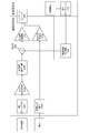
- FIG. 3 is a schematic diagram showing the configuration of the NC circuit included in the noise canceling headphones 1.
- the NC circuit includes a first buffer amplifier unit 151, a second buffer amplifier unit 152, a microphone signal amplification unit 153, a noise canceling signal generation circuit 154, a noise canceling signal amplification unit 155, a music sound input terminal 156, and music sound.
- a signal amplification unit 157 and a signal amplification unit 157 are provided.
- the first buffer amplifier unit 151 performs impedance conversion with respect to the noise signal from the first microphone 16.
- the first buffer amplifier unit 151 outputs the impedance-converted noise signal to the microphone signal amplification unit 153.
- the second buffer amplifier unit 152 performs impedance conversion with respect to the noise signal from the second microphone 17.
- the second buffer amplifier unit 152 outputs the impedance-converted noise signal to the microphone signal amplification unit 153.
- the microphone signal amplification unit 153 is a signal including an output signal from the first buffer amplifier unit 151 (noise signal corresponding to external noise) and an output signal from the second buffer amplifier unit 152 (noise signal corresponding to internal noise). (Hereinafter referred to as “synthetic signal”) is amplified.
- the microphone signal amplification unit 153 outputs the amplified combined signal to the noise canceling signal generation circuit (hereinafter referred to as “NC signal generation circuit”) 154.
- the NC signal generation circuit 154 generates a noise canceling signal based on the output signal from the microphone signal amplification unit 153 (combined signal amplified by the microphone signal amplification unit 153). That is, in the NC signal generation circuit 154, a noise canceling signal based on the external noise collected by the first microphone 16 (a noise canceling signal based on the signal from the first buffer amplifier unit 151) and the second microphone 17 are collected. A noise canceling signal including a noise canceling signal based on the sounded internal noise (a noise canceling signal based on the signal from the second buffer amplifier unit 152) is generated.
- the noise canceling signal generated by the NC signal generation circuit 154 includes a noise canceling signal having a phase opposite to that of the external noise and a noise canceling signal having a phase opposite to that of the internal noise.
- the NC signal generation circuit 154 outputs a noise canceling signal to a noise canceling signal amplification unit (hereinafter referred to as “NC signal amplification unit”) 155.
- NC signal amplification unit a noise canceling signal amplification unit
- the noise canceling signal having the opposite phase to the external noise is a signal for canceling the external noise.
- the noise canceling signal having the opposite phase to the internal noise is a signal that cancels the internal noise.
- the noise canceling signal having the opposite phase to the external noise is the first noise canceling signal in the present invention.
- the noise canceling signal having the opposite phase to the internal noise is the second noise canceling signal in the present invention.
- the NC signal amplification unit 155 amplifies the noise canceling signal (first noise canceling signal, second noise canceling signal) from the NC signal generation circuit 154.
- the output unit (not shown) of the NC signal amplification unit 155 is connected to one input unit (not shown) of the headphone unit 14.
- An audio signal (musical tone) from a sound source such as a portable musical tone player is input to the musical tone input terminal 156.
- the musical tone input terminal 156 outputs an audio signal to the musical tone signal amplification unit 157.
- the musical tone signal amplification unit 157 amplifies the audio signal from the musical tone input terminal 156.
- the output unit (not shown) of the musical tone signal amplification unit 157 is connected to the other input unit (not shown) of the headphone unit 14.
- the headphone unit 14 converts the audio signal from the sound source into sound waves (sound waves corresponding to the audio signals) and outputs the sound waves, and also converts the sound waves according to the first noise canceling signal and the second noise canceling signal. It is converted to the corresponding sound wave and output. That is, the headphone unit 14 outputs a sound wave corresponding to the musical sound signal and a sound wave corresponding to the noise canceling signal amplified by the NC signal amplification unit 155.
- the second buffer amplifier section may be an impedance conversion section included in the second microphone. That is, for example, the second microphone includes a microphone unit that converts internal noise into a noise signal, and an impedance conversion unit that converts impedance of the noise signal and outputs it.
- the impedance conversion unit of the second microphone functions as a second buffer amplifier unit. According to this configuration, the number of parts constituting the NC circuit is reduced.
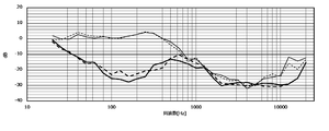
- FIG. 4 is a graph showing the canceling effect of the noise canceling headphones 1.
- the figure shows the frequency characteristics (thin line) when the noise canceling function of the noise canceling headphones 1 is off and the frequency characteristics (thick line) when the noise canceling function is on.
- the solid line shows the frequency characteristic of the left sound emitting unit 10
- the broken line shows the frequency characteristic of the right sound emitting unit 20.
- the noise canceling headphone 1 exhibits a canceling effect of attenuating the gain by about 8 dB to 30 dB, particularly in the low frequency band (about 30 Hz to 500 Hz).
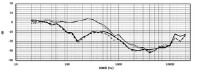
- FIG. 5 is a graph showing the canceling effect of the conventional FF type noise canceling headphones.
- the figure shows the frequency characteristics (thin line) when the noise canceling function of the conventional FF type noise canceling headphones is off and the frequency characteristics (thick line) when the same function is on.
- the solid line shows the frequency characteristic of the left sound emitting unit
- the broken line shows the frequency characteristic of the right sound emitting unit.
- the conventional FF type noise canceling headphones exhibit a canceling effect of attenuating the gain by about 6 dB to 24 dB in the low frequency band (about 80 Hz to 400 Hz).
- the canceling effect of the conventional FF type noise canceling headphones appears in a narrow frequency band, and the gain attenuation is small.
- the noise canceling headphone 1 exhibits a large canceling effect in a wide frequency band as compared with the conventional FF type noise canceling headphone.
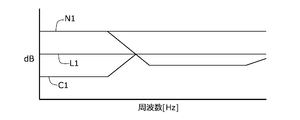
- FIG. 6 is a schematic view showing a canceling state of the conventional FF type noise canceling headphones in an ideal usage state.
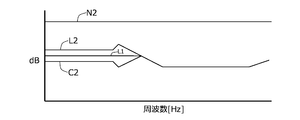
- FIG. 7 is a schematic view showing the canceling state of the conventional FF type noise canceling headphones in the actual usage state.
- the noise canceling headphones When the noise canceling headphones are attached to the user's head, the noise (high frequency component) in the high frequency band is muted (cancelled) by the shielding of the ear pads, which is a so-called passive effect. That is, in an ideal usage state (hereinafter referred to as "ideal state"), when the noise canceling headphones are attached to the user's head, the high frequency components are muted (cancelled) by the ear pads, and the high frequency components are removed. It does not reach the front air chamber. On the other hand, noise in the low frequency band of external noise (low frequency component) reaches the front air chamber in a state where the volume is reduced because the passive effect cannot be sufficiently obtained. That is, the passive effect is weak in headphones that do not have a noise canceling function.
- the noise canceling signal generation circuit (NC signal generation circuit) provided in the conventional FF type noise canceling headphones functions to cancel the low frequency component of the external noise that reaches the front air chamber because the passive effect is weak.
- the conventional noise canceling signal generation circuit performs signal processing on the collected external noise in consideration of the volume reduction due to the passive effect in the ideal state, generates a noise signal, and has the opposite phase to the generated noise signal. Generates a noise canceling signal.
- the external noise (N1) in the low frequency band is canceled by the generated noise canceling signal (C1).
- the external noise is muted (cancelled) up to a predetermined muffling level (L1).
- NC signal generation circuit in the ideal state, the user's head (temporal region) and the ear pad are in close contact with each other without a gap (the front air chamber is sealed).
- a conventional noise canceling signal generation circuit in an ideal state generates a canceling signal based on a reference characteristic based on this premise. That is, when there is a gap between the user's head (temporal region) and the ear pad and the passive effect as expected is not generated, the conventional noise canceling signal generation circuit obtains the passive effect according to the reference characteristics.
- a cancellation signal (C1) is generated based on the external noise (N1) when the noise is generated. As a result, as shown in FIG.
- N2 indicates the external noise that actually reaches the front air chamber.
- the noise canceling headphone according to the present invention contains a part (L2) of external noise in the low frequency band that remains uncancelled by the conventional FF type noise canceling headphone in the actual usage state shown in FIG.
- the noise is collected by the second microphone and a noise canceling signal (C2) having the opposite phase including the collected internal noise is generated.
- C2 noise canceling signal
- the noise canceling headphone according to the present invention generates a cancel signal according to the internal noise collected by the second microphone in addition to the external noise collected by the first microphone.
- the noise canceling headphone according to the present invention exhibits a higher canceling effect than the conventional FF type noise canceling headphone.
- FIG. 9 is a schematic diagram showing the configuration of the NC circuit included in the conventional hybrid type noise canceling headphones.
- the anterior air chamber SFA and the posterior air chamber SRA shown in the figure are the corresponding spaces of the anterior air chamber SF and the posterior air chamber SR shown in FIG.
- the NC circuit (hereinafter referred to as "conventional NC circuit") included in the conventional hybrid noise canceling headphones includes a microphone signal amplification unit 153A, an NC signal generation circuit 154A, an NC signal amplification unit 155A, and a music input terminal 156A.
- a music signal amplification unit 157A, an error correction NC circuit 18A, and an adder 19A are provided. That is, the conventional NC circuit includes an error correction NC circuit 18A and an adder 19A as compared with the NC circuit included in the noise canceling headphones 1 shown in FIG.
- the functions and configurations of the musical sound input terminal 156A, the musical sound signal amplification unit 157A, the first microphone 16A, and the second microphone 17A shown in FIG. 3 are the musical sound input terminal 156, the musical sound signal amplification unit 157, and the first microphone shown in FIG.
- the functions and configurations of the microphone 16 and the second microphone 17 are the same. Therefore, specific description of each of the musical tone input terminal 156A, the musical tone signal amplification unit 157A, the first microphone 16A, and the second microphone 17A will be omitted.
- the microphone signal amplification unit 153A amplifies the noise signal from the first microphone 16A.
- the NC signal generation circuit 154A generates a noise canceling signal based on the output signal from the microphone signal amplification unit 153A.
- the NC signal generation circuit 154A generates a noise canceling signal having a phase opposite to the external noise collected by the first microphone 16A.
- the NC signal generation circuit 154A outputs a noise canceling signal to the NC signal amplification unit 155A via the adder 19A.
- the adder 19A and the NC signal amplification unit 155A will be described later.
- the error correction NC circuit 18A generates an error correction signal for canceling noise that could not be completely muted by the cancel signal corresponding to the noise signal from the first microphone 16A (hereinafter referred to as "error noise").
- error noise an error correction signal for canceling noise that could not be completely muted by the cancel signal corresponding to the noise signal from the first microphone 16A (hereinafter referred to as "error noise").
- the second microphone 17A collects the error noise, generates a noise signal corresponding to the error signal, and outputs the noise signal to the error correction NC circuit 18A.
- the error correction NC circuit 18A outputs an error correction signal to the adder 19A.
- the adder 19A adds the noise canceling signal from the NC signal generation circuit 154A and the error correction signal from the error correction NC circuit 18A.
- the adder 19A outputs the adder signal to the NC signal amplification unit 155A.
- the NC signal amplification unit 155A amplifies the addition signal (noise cancel signal and error correction signal) generated by being added by the adder 19A.
- the output unit (not shown) of the NC signal amplification unit 155A is connected to one input unit (not shown) of the headphone unit 14A.
- the NC circuit provided in the conventional hybrid type noise canceling headphone includes the second microphone 17A and the error correction NC circuit 18A in addition to the NC circuit provided in the conventional FF type noise canceling headphone. , The adder 19A.
- the NC circuit included in the noise canceling headphone 1 is composed of a second microphone 17 and a second buffer amplifier unit 152 in addition to the NC circuit included in the conventional FF type noise canceling headphone. That is, the second microphone 17 and the second buffer amplifier unit 152 function as a filter that silences noise from the gap between the user's head (temporal head) and the ear pad. Further, the second microphone 17 and the second buffer amplifier unit 152 provide a noise canceling signal for user-specific noise caused by individual differences in the gap between the user's head (temporal region) and ear pads. Correct automatically.
- the second buffer amplifier unit may be an impedance conversion unit included in the second microphone.
- the NC circuit included in the noise canceling headphones according to the present invention is configured by adding only the second microphone to the NC circuit provided in the conventional FF type noise canceling headphones. That is, the noise canceling headphone according to the present invention reduces signal processing according to the noise signal, and realizes a canceling effect equivalent to that of the conventional hybrid system by a simple NC circuit.
- the NC circuit included in the noise canceling headphones according to the present invention has an expensive error correction NC circuit or a complicated configuration like the NC circuit provided in the conventional hybrid type noise canceling headphones. Does not require an adder. That is, the NC circuit included in the noise canceling headphones according to the present invention has a simpler configuration than the NC circuit included in the conventional hybrid noise canceling headphones.
- the noise canceling headphones according to the present invention realize a higher canceling effect as compared with the conventional FF type noise canceling headphones. As described above, the noise canceling headphone according to the present invention realizes a high canceling effect with a simple configuration.
- Noise canceling headphones 10 Left sound emitting unit 11 Housing 11h Sound collecting hole (1st sound collecting hole) 12 Earpad 13 Baffle plate 13h Sound collecting hole (2nd sound collecting hole) 14 Headphone unit 15 Board 151 1st buffer amplifier section 152 2nd buffer amplifier section 153 Microphone signal amplification section 154 Noise cancellation signal generation circuit (NC signal generation circuit) 155 Noise canceling signal amplification unit (NC signal amplification unit) 156 Musical tone input terminal 157 Musical tone signal amplification unit 16 1st microphone 17 2nd microphone 20 Right sound emitting unit 21 Housing 22 Ear pads 23 Baffle plate 30 Connecting member SF Front air chamber SR Rear air chamber
Landscapes
- Engineering & Computer Science (AREA)
- Physics & Mathematics (AREA)
- Acoustics & Sound (AREA)
- Signal Processing (AREA)
- Multimedia (AREA)
- Manufacturing & Machinery (AREA)
- Health & Medical Sciences (AREA)
- Audiology, Speech & Language Pathology (AREA)
- General Health & Medical Sciences (AREA)
- Soundproofing, Sound Blocking, And Sound Damping (AREA)
Abstract
Description
同図は、ノイズキャンセルヘッドホン1と側頭部HDとの間に前気室SFが構成されていることを示す。また、同図は、バッフル板13により前気室SFと後気室SRとが区分けされていることを示す。
図7は、実際の使用状態における従来のFF方式のノイズキャンセルヘッドホンのキャンセルの状態を示す模式図である。
10 左放音ユニット
11 ハウジング
11h 集音孔(第1集音孔)
12 イヤパッド
13 バッフル板
13h 集音孔(第2集音孔)
14 ヘッドホンユニット
15 基板
151 第1バッファアンプ部
152 第2バッファアンプ部
153 マイク信号増幅部
154 ノイズキャンセル信号発生回路(NC信号発生回路)
155 ノイズキャンセル信号増幅部(NC信号増幅部)
156 楽音入力端子
157 楽音信号増幅部
16 第1マイクロホン
17 第2マイクロホン
20 右放音ユニット
21 ハウジング
22 イヤパッド
23 バッフル板
30 連結部材
SF 前気室
SR 後気室
Claims (7)
- 音声信号に応じた音波を出力するヘッドホンユニットと、
前記ヘッドホンユニットが取り付けられるバッフル板と、
前記バッフル板に取り付けられるイヤパッドと、
前記バッフル板に取り付けられるハウジングと、
前記ハウジングの外部の外部騒音を集音する第1マイクロホンと、
前記第1マイクロホンからの信号に対してインピーダンス変換をして出力する第1バッファアンプ部と、
ユーザの頭部に装着されたときに、前記ヘッドホンユニットと前記バッフル板と前記イヤパッドと前記ユーザの頭部とで形成される前気室の内部の内部騒音を集音する第2マイクロホンと、
前記第2マイクロホンからの信号に対してインピーダンス変換をして出力する第2バッファアンプ部と、
前記第1バッファアンプ部からの信号と、前記第2バッファアンプ部からの信号とが、合成された合成信号に基づいて、ノイズキャンセル信号を生成するノイズキャンセル信号発生回路と、
を有してなる、
ことを特徴とするノイズキャンセルヘッドホン。 - 前記ノイズキャンセル信号は、
前記外部騒音と逆位相の第1ノイズキャンセル信号と、
前記内部騒音と逆位相の第2ノイズキャンセル信号と、
を含む、
請求項1記載のノイズキャンセルヘッドホン。 - 前記合成信号を増幅するマイク信号増幅部、
を有してなり、
前記ノイズキャンセル信号発生回路は、前記マイク信号増幅部により増幅された前記合成信号に基づいて、前記ノイズキャンセル信号を生成する、
請求項1記載のノイズキャンセルヘッドホン。 - 前記第2バッファアンプ部は、前記第2マイクロホンが備えるインピーダンス変換部である、
請求項1記載のノイズキャンセルヘッドホン。 - 前記第1マイクロホンは、
前記ヘッドホンユニットと前記バッフル板と前記ハウジングとで形成される後気室の内部に配置される、
請求項1記載のノイズキャンセルヘッドホン。 - 前記第1マイクロホンは、前記ハウジングに取り付けられ、
前記第1マイクロホンの集音部は、前記ハウジングの外部に露出する、
請求項1記載のノイズキャンセルヘッドホン。 - 前記第2マイクロホンは、前記バッフル板に取り付けられ、
前記第2マイクロホンの集音部は、前記前気室に露出する、
請求項1記載のノイズキャンセルヘッドホン。
Priority Applications (5)
| Application Number | Priority Date | Filing Date | Title |
|---|---|---|---|
| JP2022511520A JP7653714B2 (ja) | 2020-04-03 | 2020-12-01 | ノイズキャンセルヘッドホン |
| KR1020227029321A KR102724334B1 (ko) | 2020-04-03 | 2020-12-01 | 노이즈 캔슬 헤드폰 |
| US17/995,013 US12075219B2 (en) | 2020-04-03 | 2020-12-01 | Noise-cancelling headphone |
| CN202080098118.6A CN115244945B (zh) | 2020-04-03 | 2020-12-01 | 头戴式消噪耳机 |
| EP20929345.5A EP4131996B1 (en) | 2020-04-03 | 2020-12-01 | Noise canceling headphone |
Applications Claiming Priority (2)
| Application Number | Priority Date | Filing Date | Title |
|---|---|---|---|
| JP2020067948 | 2020-04-03 | ||
| JP2020-067948 | 2020-04-03 |
Publications (1)
| Publication Number | Publication Date |
|---|---|
| WO2021199498A1 true WO2021199498A1 (ja) | 2021-10-07 |
Family
ID=77927187
Family Applications (1)
| Application Number | Title | Priority Date | Filing Date |
|---|---|---|---|
| PCT/JP2020/044725 Ceased WO2021199498A1 (ja) | 2020-04-03 | 2020-12-01 | ノイズキャンセルヘッドホン |
Country Status (6)
| Country | Link |
|---|---|
| US (1) | US12075219B2 (ja) |
| EP (1) | EP4131996B1 (ja) |
| JP (1) | JP7653714B2 (ja) |
| KR (1) | KR102724334B1 (ja) |
| CN (1) | CN115244945B (ja) |
| WO (1) | WO2021199498A1 (ja) |
Families Citing this family (2)
| Publication number | Priority date | Publication date | Assignee | Title |
|---|---|---|---|---|
| USD1008997S1 (en) * | 2023-08-20 | 2023-12-26 | Weihan Lin | Headphone |
| CN116939428B (zh) * | 2023-09-18 | 2023-12-22 | 歌尔股份有限公司 | 耳机设备、风噪抑制方法及计算机可读存储介质 |
Citations (5)
| Publication number | Priority date | Publication date | Assignee | Title |
|---|---|---|---|---|
| JP2007028354A (ja) * | 2005-07-20 | 2007-02-01 | Audio Technica Corp | ノイズキャンセルヘッドホン |
| WO2009041012A1 (ja) * | 2007-09-28 | 2009-04-02 | Dimagic Co., Ltd. | ノイズ制御システム |
| US20110158419A1 (en) * | 2009-12-30 | 2011-06-30 | Lalin Theverapperuma | Adaptive digital noise canceller |
| JP2012023637A (ja) * | 2010-07-15 | 2012-02-02 | Audio Technica Corp | ノイズキャンセルヘッドホン |
| US20140169579A1 (en) * | 2012-12-18 | 2014-06-19 | Apple Inc. | Hybrid adaptive headphone |
Family Cites Families (7)
| Publication number | Priority date | Publication date | Assignee | Title |
|---|---|---|---|---|
| GB2434708B (en) * | 2006-01-26 | 2008-02-27 | Sonaptic Ltd | Ambient noise reduction arrangements |
| JP5610945B2 (ja) * | 2010-09-15 | 2014-10-22 | 株式会社オーディオテクニカ | ノイズキャンセルヘッドホン及びノイズキャンセルイヤーマフ |
| JP5799650B2 (ja) * | 2011-08-11 | 2015-10-28 | ソニー株式会社 | ヘッドホン装置 |
| GB201421291D0 (en) * | 2014-12-01 | 2015-01-14 | Soundchip Sa | Earphone system |
| US10080078B2 (en) * | 2016-09-16 | 2018-09-18 | Intel Corporation | Battery-less, noise-cancellation headset |
| US10567863B2 (en) * | 2017-12-19 | 2020-02-18 | Revx Technologies, Inc. | System and method for configuring audio signals to compensate for acoustic changes of the ear |
| JP6798717B2 (ja) * | 2019-07-18 | 2020-12-09 | 株式会社オーディオテクニカ | ノイズキャンセルヘッドホン |
-
2020
- 2020-12-01 EP EP20929345.5A patent/EP4131996B1/en active Active
- 2020-12-01 JP JP2022511520A patent/JP7653714B2/ja active Active
- 2020-12-01 US US17/995,013 patent/US12075219B2/en active Active
- 2020-12-01 CN CN202080098118.6A patent/CN115244945B/zh active Active
- 2020-12-01 WO PCT/JP2020/044725 patent/WO2021199498A1/ja not_active Ceased
- 2020-12-01 KR KR1020227029321A patent/KR102724334B1/ko active Active
Patent Citations (5)
| Publication number | Priority date | Publication date | Assignee | Title |
|---|---|---|---|---|
| JP2007028354A (ja) * | 2005-07-20 | 2007-02-01 | Audio Technica Corp | ノイズキャンセルヘッドホン |
| WO2009041012A1 (ja) * | 2007-09-28 | 2009-04-02 | Dimagic Co., Ltd. | ノイズ制御システム |
| US20110158419A1 (en) * | 2009-12-30 | 2011-06-30 | Lalin Theverapperuma | Adaptive digital noise canceller |
| JP2012023637A (ja) * | 2010-07-15 | 2012-02-02 | Audio Technica Corp | ノイズキャンセルヘッドホン |
| US20140169579A1 (en) * | 2012-12-18 | 2014-06-19 | Apple Inc. | Hybrid adaptive headphone |
Non-Patent Citations (1)
| Title |
|---|
| See also references of EP4131996A4 * |
Also Published As
| Publication number | Publication date |
|---|---|
| US12075219B2 (en) | 2024-08-27 |
| US20230164486A1 (en) | 2023-05-25 |
| KR20220163357A (ko) | 2022-12-09 |
| EP4131996B1 (en) | 2025-09-17 |
| JP7653714B2 (ja) | 2025-03-31 |
| EP4131996A1 (en) | 2023-02-08 |
| EP4131996C0 (en) | 2025-09-17 |
| JPWO2021199498A1 (ja) | 2021-10-07 |
| CN115244945A (zh) | 2022-10-25 |
| CN115244945B (zh) | 2025-05-23 |
| EP4131996A4 (en) | 2024-04-24 |
| KR102724334B1 (ko) | 2024-11-01 |
Similar Documents
| Publication | Publication Date | Title |
|---|---|---|
| KR100935769B1 (ko) | 피드백 제어를 갖는 주파수 특성 보상형 능동형 소음 제어장치 및 방법 | |
| US7466838B1 (en) | Electroacoustic devices with noise-reducing capability | |
| JP5363825B2 (ja) | ノイズキャンセルヘッドホン | |
| US7043037B2 (en) | Hearing aid having acoustical feedback protection | |
| CN101577847B (zh) | 信号处理设备和信号处理方法 | |
| CN114902693A (zh) | 声音输出装置 | |
| US20130129105A1 (en) | Audio headset with active noise control of the non-adaptive type for listening to an audio music source and/or for "hands-free" telephony functions | |
| CN102340717A (zh) | 头戴式消噪耳机 | |
| US6714654B2 (en) | Hearing aid operative to cancel sounds propagating through the hearing aid case | |
| JP2010050739A (ja) | ノイズキャンセルシステム | |
| JP7687333B2 (ja) | 音響再生装置、信号処理装置、信号処理方法 | |
| EP2830324A1 (en) | Headphone and headset | |
| CN114787911A (zh) | 耳戴式播放设备的噪声消除系统和信号处理方法 | |
| JP7653714B2 (ja) | ノイズキャンセルヘッドホン | |
| CN204305320U (zh) | 降噪耳机 | |
| CN109151632B (zh) | 头戴式耳机 | |
| JP6953984B2 (ja) | イヤホンおよびイヤホンの信号処理方法 | |
| JP2019198113A (ja) | ノイズキャンセルヘッドホン | |
| JPH02224498A (ja) | アクティブ・ノイズ・キャンセラー | |
| CN222302020U (zh) | 耳戴式听力设备 | |
| WO2026099995A1 (ja) | 音響放音装置 | |
| US20230026002A1 (en) | Non-acoustic sensor for active noise cancellation | |
| CN122054032A (zh) | 一种耳机 | |
| JP6297950B2 (ja) | こもり音低減装置及びそれを備えた補聴器、オーディオ用イヤホン、耳せん、並びに電気音響変換器 | |
| JP6081854B2 (ja) | こもり音低減装置及びそれを備えた補聴器、オーディオ用イヤホン、耳せん |
Legal Events
| Date | Code | Title | Description |
|---|---|---|---|
| 121 | Ep: the epo has been informed by wipo that ep was designated in this application |
Ref document number: 20929345 Country of ref document: EP Kind code of ref document: A1 |
|
| ENP | Entry into the national phase |
Ref document number: 2022511520 Country of ref document: JP Kind code of ref document: A |
|
| WWE | Wipo information: entry into national phase |
Ref document number: 2020929345 Country of ref document: EP |
|
| ENP | Entry into the national phase |
Ref document number: 2020929345 Country of ref document: EP Effective date: 20221103 |
|
| NENP | Non-entry into the national phase |
Ref country code: DE |
|
| WWG | Wipo information: grant in national office |
Ref document number: 202080098118.6 Country of ref document: CN |
|
| WWG | Wipo information: grant in national office |
Ref document number: 2020929345 Country of ref document: EP |